JP2013093973A - Holder device for charging type electric apparatus - Google Patents
Holder device for charging type electric apparatusDownload PDFInfo
- Publication number
- JP2013093973A JP2013093973AJP2011234559AJP2011234559AJP2013093973AJP 2013093973 AJP2013093973 AJP 2013093973AJP 2011234559 AJP2011234559 AJP 2011234559AJP 2011234559 AJP2011234559 AJP 2011234559AJP 2013093973 AJP2013093973 AJP 2013093973A
- Authority
- JP
- Japan
- Prior art keywords
- charging
- bottom wall
- pair
- gripping
- mounting surface
- Prior art date
- Legal status (The legal status is an assumption and is not a legal conclusion. Google has not performed a legal analysis and makes no representation as to the accuracy of the status listed.)
- Pending
Links
- 239000011347resinSubstances0.000claimsdescription5
- 229920005989resinPolymers0.000claimsdescription5
- 239000007779soft materialSubstances0.000claimsdescription5
- 230000005484gravityEffects0.000claimsdescription2
- 230000005611electricityEffects0.000claims1
- 230000005540biological transmissionEffects0.000description8
- 230000001133accelerationEffects0.000description5
- 238000000034methodMethods0.000description4
- 230000007257malfunctionEffects0.000description3
- 239000000463materialSubstances0.000description3
- 239000002184metalSubstances0.000description3
- 238000003860storageMethods0.000description3
- 238000013459approachMethods0.000description2
- 230000006835compressionEffects0.000description2
- 238000007906compressionMethods0.000description2
- 230000007797corrosionEffects0.000description2
- 238000005260corrosionMethods0.000description2
- 230000000694effectsEffects0.000description2
- 229920001971elastomerPolymers0.000description2
- 238000003780insertionMethods0.000description2
- 230000037431insertionEffects0.000description2
- 230000002093peripheral effectEffects0.000description2
- 239000005060rubberSubstances0.000description2
- 229920002943EPDM rubberPolymers0.000description1
- JOYRKODLDBILNP-UHFFFAOYSA-NEthyl urethaneChemical compoundCCOC(N)=OJOYRKODLDBILNP-UHFFFAOYSA-N0.000description1
- 210000000078clawAnatomy0.000description1
- 230000007423decreaseEffects0.000description1
- 230000005489elastic deformationEffects0.000description1
- 230000005674electromagnetic inductionEffects0.000description1
- 239000012212insulatorSubstances0.000description1
- 238000005304joiningMethods0.000description1
- 238000004519manufacturing processMethods0.000description1
- 238000003825pressingMethods0.000description1
- 229920002725thermoplastic elastomerPolymers0.000description1
- XLYOFNOQVPJJNP-UHFFFAOYSA-NwaterSubstancesOXLYOFNOQVPJJNP-UHFFFAOYSA-N0.000description1
Images


Classifications
- Y—GENERAL TAGGING OF NEW TECHNOLOGICAL DEVELOPMENTS; GENERAL TAGGING OF CROSS-SECTIONAL TECHNOLOGIES SPANNING OVER SEVERAL SECTIONS OF THE IPC; TECHNICAL SUBJECTS COVERED BY FORMER USPC CROSS-REFERENCE ART COLLECTIONS [XRACs] AND DIGESTS
- Y02—TECHNOLOGIES OR APPLICATIONS FOR MITIGATION OR ADAPTATION AGAINST CLIMATE CHANGE
- Y02E—REDUCTION OF GREENHOUSE GAS [GHG] EMISSIONS, RELATED TO ENERGY GENERATION, TRANSMISSION OR DISTRIBUTION
- Y02E60/00—Enabling technologies; Technologies with a potential or indirect contribution to GHG emissions mitigation
- Y02E60/10—Energy storage using batteries
Landscapes
- Charge And Discharge Circuits For Batteries Or The Like (AREA)
- Secondary Cells (AREA)
Abstract
Description
Translated fromJapanese本発明は、非接触式充電装置によって充電される充電式電気機器用のホルダ装置に関し、詳しくは車両室内などに設けられるホルダ装置に関するものである。 The present invention relates to a holder device for a rechargeable electric device that is charged by a non-contact charging device, and more particularly to a holder device provided in a vehicle interior or the like.
近年、繰り返し充電が行える二次電池、その二次電池を用いた携帯電話、コードレス電話機、ポータブルゲーム機、ポータブル音響機器、電動歯ブラシ、電動シェーバー等の充電式電気機器(以下、電気機器という)が広く用いられている。その電気機器を充電するには、一般に有接点型の接触式充電装置が用いられているが、接点端子の腐食による接触不良が生じるなどの不具合があった。 In recent years, rechargeable batteries that can be repeatedly charged, rechargeable electric devices (hereinafter referred to as electric devices) such as mobile phones, cordless phones, portable game machines, portable audio devices, electric toothbrushes, and electric shavers using the secondary batteries. Widely used. In order to charge the electric device, a contact type contact charging device is generally used, but there are problems such as contact failure due to corrosion of contact terminals.
そこで、コイルによる電磁誘導を利用した無接点型の非接触式充電方法が開発されている。この充電方法は、非接触式充電装置(以下、充電装置という)内に設けられた一次コイルに電流を流すことで、電気機器内に設けられた二次コイルに生じる誘導電流を利用して、電気機器を充電するものである。この非接触式充電方法によれば、無接点であるため腐食による接触不良を回避できる他、接点端子に人が触れることや水の付着による短絡も未然に防止できる。また一つの充電装置を複数種の電気機器の充電に共用することができ、経済的である。 Therefore, a contactless non-contact charging method using electromagnetic induction by a coil has been developed. This charging method uses an induced current generated in a secondary coil provided in an electric device by causing a current to flow in a primary coil provided in a non-contact charging device (hereinafter referred to as a charging device), It is for charging electrical equipment. According to this non-contact type charging method, contact failure due to corrosion can be avoided because it is a non-contact type, and it is also possible to prevent a short circuit caused by a person touching a contact terminal or adhering water. Moreover, one charging device can be shared for charging a plurality of types of electrical equipment, which is economical.
ところで、自動車室内などに充電装置を配置し、乗車中に電気機器を充電することが考えられている。しかしながら、上記した非接触式充電方法においては、一次コイルと二次コイルとをほぼ同軸に位置させなければならない。また一次コイルと二次コイルとの間の距離が大きく離れると充電が困難となる。したがって自動車室内のように振動や加減速が発生する場所では、振動や加減速による充電装置と電気機器との相対移動を規制する必要がある。 By the way, it is considered that a charging device is arranged in an automobile room or the like to charge an electric device while riding. However, in the non-contact charging method described above, the primary coil and the secondary coil must be positioned substantially coaxially. In addition, when the distance between the primary coil and the secondary coil is greatly separated, charging becomes difficult. Therefore, in a place where vibration or acceleration / deceleration occurs, such as in an automobile interior, it is necessary to regulate the relative movement between the charging device and the electric device due to vibration or acceleration / deceleration.
そこで特開2003−047180号公報には、充電装置に電気機器の胴部を囲う支持部を設け、支持部に一次コイルを配置すると共に、電気機器に長手方向を軸とする二次コイルを配置した無接点型充電装置が提案されている。このようにすれば、上記不具合は解消されるものの、一つの充電装置を複数種の電気機器の充電に共用しようとすると、複数種の電気機器全てに長手方向を軸とする二次コイルを配置しなけらばならず、経済効果が低下してしまう。 Therefore, in Japanese Patent Laid-Open No. 2003-047180, the charging device is provided with a support portion that encloses the body portion of the electric device, and the primary coil is disposed on the support portion, and the secondary coil having the longitudinal direction as the axis is disposed on the electric device. A contactless charging device has been proposed. In this way, although the above problem is solved, if one charging device is shared for charging a plurality of types of electrical equipment, a secondary coil having a longitudinal axis as an axis is arranged in all the types of electrical equipment. It must be done and the economic effect will decline.
また特開2008−295273号公報には、端末装填部(充電装置)内に携帯電話端末(電気機器)が差し込まれた時に、携帯電話端末の上下方向、幅方向、厚さ方向のそれぞれに対して携帯電話端末を押さえて支持する押さえ部を設けた無接点電力電送装置が提案されている。しかしこの装置では、構造が複雑になって高価となるという不具合がある。 Japanese Patent Laid-Open No. 2008-295273 discloses that when a mobile phone terminal (electrical device) is inserted into the terminal loading unit (charging device), the mobile phone terminal has a vertical direction, a width direction, and a thickness direction. There has been proposed a non-contact power transmission device provided with a pressing portion that holds and supports a mobile phone terminal. However, this apparatus has a problem that the structure becomes complicated and expensive.
本発明は上記した事情に鑑みてなされたものであり、簡単な構造で充電装置と電気機器との相対移動を規制することを解決すべき課題とする。 The present invention has been made in view of the above-described circumstances, and an object to be solved is to regulate the relative movement between the charging device and the electric device with a simple structure.
上記課題を解決する本発明の充電式電気機器用ホルダ装置の特徴は、充電時には、充電装置の載置表面と電気機器の充電表面とが対向して直接又は間接的に接触するように電気機器が収納されるホルダ装置であって、
載置表面に少なくとも一部が当接し載置表面と充電表面との間に介在する底壁と、底壁及び底壁と対向する対向壁の少なくとも一方から突出し電気機器を両側から把持する少なくとも一対の把持突起と、一対の把持突起を互いに近接する方向へ付勢する付勢部材と、を有し、
少なくとも一対の把持突起はショアA90以下の軟質材から形成され、充電時には、一対の把持突起は付勢部材の付勢によって電気機器を把持するとともに充電表面が載置表面に向かって押圧されることにある。The feature of the holder device for a rechargeable electric device according to the present invention that solves the above-described problems is that the electric device is placed so that the mounting surface of the charging device and the charging surface of the electric device face each other directly or indirectly during charging. Is a holder device for storing,
At least a pair that protrudes from at least one of a bottom wall that is at least partially in contact with the mounting surface and that is interposed between the mounting surface and the charging surface, and a bottom wall and an opposing wall that faces the bottom wall, and grips an electrical device from both sides. And a biasing member that biases the pair of gripping protrusions in a direction approaching each other,
At least a pair of gripping protrusions are formed from a soft material of Shore A 90 or less, and at the time of charging, the pair of gripping protrusions grips the electric device by the biasing member and the charging surface is pressed toward the mounting surface. It is in.
本発明のホルダ装置によれば、充電時には、一対の把持突起と底壁との間に電気機器を挿入するだけで、充電表面が載置表面に向かって押圧されるので、一次コイルと二次コイルとが近接し、伝送損失を低減した充電が可能となる。また、少なくとも一対の把持突起で電気機器を安定して把持することができるので、車室内に搭載した場合であっても、振動や加減速によって位置ずれすることなく、安定した充電が可能となる。 According to the holder device of the present invention, at the time of charging, the charging surface is pressed toward the mounting surface simply by inserting an electric device between the pair of gripping protrusions and the bottom wall. Charging with reduced transmission loss is possible due to the proximity of the coil. In addition, since the electric device can be stably gripped by at least a pair of gripping protrusions, stable charging is possible without being displaced due to vibration or acceleration / deceleration even when mounted in the passenger compartment. .
本発明の充電式電気機器用ホルダ装置の特徴は、充電時には、充電装置の載置表面と電気機器の充電表面とが対向して直接又は間接的に接触するように電気機器が収納されることにある。充電装置の載置表面とは、充電時に電気機器が対向する表面であり、一般には充電装置に配置された一次コイルの軸に対して直交する表面をいう。また電気機器の充電表面とは、充電時に充電装置の載置表面に対向して配置される表面をいう。 A feature of the holder device for a rechargeable electric device according to the present invention is that the electric device is stored so that the mounting surface of the charging device and the charging surface of the electric device face each other directly or indirectly during charging. It is in. The mounting surface of the charging device is a surface on which an electric device faces during charging, and generally refers to a surface orthogonal to the axis of the primary coil disposed in the charging device. Moreover, the charging surface of an electric device refers to the surface arrange | positioned facing the mounting surface of a charging device at the time of charge.
充電装置としては、公知の種々の非接触式充電装置を用いることができる。一次コイルの配置も、可動コイル型、コイルアレイ型などを用いることができる。また電気機器としては、二次電池自体、その二次電池を用いた携帯電話、コードレス電話機、ポータブルゲーム機、ポータブル音響機器、電動歯ブラシ、電動シェーバー等がある。二次コイルを備えていることが望ましいが、二次コイルを備えていない電気機器であっても、二次コイルを内蔵したケースに入れたものをホルダ装置に収納して充電することもできる。 As the charging device, various known non-contact charging devices can be used. As the arrangement of the primary coil, a movable coil type, a coil array type, or the like can be used. Examples of the electric device include a secondary battery itself, a mobile phone using the secondary battery, a cordless phone, a portable game machine, a portable audio device, an electric toothbrush, and an electric shaver. Although it is desirable to include a secondary coil, even an electric device that does not include a secondary coil can be charged by being stored in a holder device in a case in which the secondary coil is incorporated.
本発明の充電式電気機器用ホルダ装置は、底壁と、底壁及び底壁と対向する対向壁の少なくとも一方から突出した少なくとも一対の把持突起と、一対の把持突起を互いに近接する方向へ付勢する付勢部材と、を有している。 A holder device for a rechargeable electric device according to the present invention is provided with a bottom wall, at least a pair of gripping protrusions protruding from at least one of the bottom wall and an opposing wall facing the bottom wall, and a pair of gripping protrusions in a direction close to each other. And a biasing member for biasing.
少なくとも一対の把持突起は、ショアA90以下の軟質材から形成され、付勢部材によって互いに近接する方向へ付勢されている。このような軟質材としては、EPDMなどのゴム類、熱可塑性エラストマー、ウレタンスポンジなどから選択して用いることができる。 At least a pair of gripping projections are formed of a soft material having a Shore A 90 or lower and are urged toward each other by an urging member. Such a soft material can be selected from rubbers such as EPDM, thermoplastic elastomer, urethane sponge, and the like.
一対の把持突起を底壁に突設した場合には、一対の把持突起は互いに近接する方向へ底壁に対して傾斜して突設されていることが望ましい。こうすることで、厚さ寸法や幅寸法が異なる複数種類の電気機器であっても、その側面と表面との角部に把持突起を圧接させることができ、付勢部材の付勢力によって充電表面を載置表面に向かって押圧することができる。 In the case where the pair of gripping protrusions protrudes from the bottom wall, it is desirable that the pair of gripping protrusions protrude from the bottom wall in a direction approaching each other. In this way, even with a plurality of types of electrical equipment having different thickness dimensions and width dimensions, the gripping protrusions can be pressed against the corners of the side surfaces and the surface, and the charging surface can be driven by the biasing force of the biasing member. Can be pressed toward the mounting surface.
また一対の把持突起を対向壁に形成した場合には、把持突起は断面円弧状に突出する形状とすることが望ましい。こうすることで、厚さ寸法や幅寸法が異なる複数種類の電気機器であっても、その側面と表面との角部に把持突起を圧接させることができ、付勢部材の付勢力によって充電表面を載置表面に向かって押圧することができる。 When a pair of gripping protrusions are formed on the opposing wall, it is desirable that the gripping protrusions have a shape that protrudes in an arc shape in cross section. In this way, even with a plurality of types of electrical equipment having different thickness dimensions and width dimensions, the gripping protrusions can be pressed against the corners of the side surfaces and the surface, and the charging surface can be driven by the biasing force of the biasing member. Can be pressed toward the mounting surface.
付勢部材としては、板バネ、コイルバネあるいは樹脂バネなどを用いることができる。付勢部材の配置の態様としては、一対の把持突起のそれぞれの内部に板バネを収納したり、一対の把持突起をコイルバネあるいはゴムバネで連結したりすることができる。一対の把持突起を中空形状とすれば、付勢部材をその内部に収納することができる。 As the urging member, a leaf spring, a coil spring, a resin spring, or the like can be used. As a mode of arrangement of the urging members, a leaf spring can be accommodated in each of the pair of gripping protrusions, or the pair of gripping protrusions can be connected by a coil spring or a rubber spring. If the pair of gripping projections are hollow, the urging member can be accommodated therein.
なお付勢部材が金属製であると、充電装置がその存在を検出して誤作動する場合が想定される。したがって付勢部材が金属製である場合には、付勢部材と載置表面との距離を大きくしたり、付勢部材と載置表面との間に絶縁体を配置したりすることが望ましい。また付勢部材を樹脂製とすれば、このような不具合を未然に回避することができる。さらに、底壁と対向する対向壁に一対の把持突起を形成すれば、付勢部材と充電装置との距離を大きくすることができるので、誤作動をさらに防止することができる。 If the biasing member is made of metal, a case where the charging device detects its presence and malfunctions is assumed. Therefore, when the urging member is made of metal, it is desirable to increase the distance between the urging member and the mounting surface, or to dispose an insulator between the urging member and the mounting surface. If the urging member is made of resin, such a problem can be avoided in advance. Furthermore, if a pair of gripping protrusions are formed on the opposing wall that faces the bottom wall, the distance between the biasing member and the charging device can be increased, so that malfunction can be further prevented.
底壁は、充電表面と載置表面との間に介在している。伝送効率を高めるためには、底壁の厚さは薄いほど好ましい。底壁を把持突起と同材質の軟質材から一体に形成すれば、充電時に電気機器によって圧縮されることで底壁をさらに薄くすることができる。しかし底壁を薄くすると、ホルダ装置としての形状保持が困難となる。 The bottom wall is interposed between the charging surface and the mounting surface. In order to increase transmission efficiency, the bottom wall is preferably as thin as possible. If the bottom wall is integrally formed from a soft material of the same material as the gripping protrusion, the bottom wall can be made thinner by being compressed by the electric device during charging. However, if the bottom wall is made thin, it is difficult to maintain the shape as the holder device.
そこで底壁と充電装置とを一体とすることが望ましい。例えば底壁周囲から把持突起と反対側へ突出する立て壁を底壁と一体に形成して箱状とし、その内部に充電装置を収納して一体化することができる。このように本発明のホルダ装置と充電装置とを一体とすることで、汎用性が向上するという効果が発現される。なお一体性をさらに高めるには、底壁は充電装置に係合固定されていることが望ましい。この係合固定手段は特に制限されず、接合、凹凸嵌合、爪係合、ビス固定など、種々の手段から選択することができる。 Therefore, it is desirable to integrate the bottom wall and the charging device. For example, a standing wall that protrudes from the periphery of the bottom wall to the opposite side of the gripping protrusion can be formed integrally with the bottom wall to form a box, and the charging device can be housed and integrated therein. Thus, the effect that versatility improves is expressed by uniting the holder apparatus and charging device of this invention. In order to further enhance the unity, it is desirable that the bottom wall is engaged and fixed to the charging device. The engagement fixing means is not particularly limited, and can be selected from various means such as joining, concave / convex fitting, claw engagement, and screw fixing.
底壁及び対向壁の少なくとも一方から立ち上がり、電気機器の重力を受けて支持する支持壁をさらに有することが望ましい。このようにすることで、把持突起と支持壁とで電気機器を少なくとも三方から支持することができ、安定して保持することができる。この支持壁は、底壁又は対向壁に突設してもよいし、他部品の一部を支持壁として代用することも可能である。 It is desirable to further have a support wall that rises from at least one of the bottom wall and the opposing wall and supports the electric device by receiving the gravity of the electric device. In this way, the electric device can be supported from at least three sides by the gripping protrusion and the support wall, and can be stably held. This support wall may protrude from the bottom wall or the opposing wall, or a part of another part can be used as a support wall.
底壁は載置表面の全面を覆うように形成してもよいが、伝送効率をより高めるためには、底壁に載置表面が表出する開口を形成することが好ましい。この開口は、電気機器を収納したときの少なくとも二次コイルに対応する位置に形成することが望ましい。このようにすることで、充電表面と載置表面との距離をより小さくすることができ、伝送効率をより高めることができる。 The bottom wall may be formed so as to cover the entire surface of the placement surface. However, in order to further improve the transmission efficiency, it is preferable to form an opening in the bottom wall where the placement surface is exposed. This opening is desirably formed at a position corresponding to at least the secondary coil when the electric device is accommodated. By doing in this way, the distance of a charge surface and a mounting surface can be made smaller, and transmission efficiency can be improved more.
また製造の容易性を考慮すると、底壁、少なくとも一対の把持突起、支持壁は、同一材料から一体に形成することが望ましい。 In consideration of ease of manufacturing, it is desirable that the bottom wall, at least the pair of gripping protrusions, and the support wall are integrally formed from the same material.
以下、実施例により本発明の実施態様を詳細に説明する。 Hereinafter, embodiments of the present invention will be described in detail by way of examples.
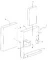
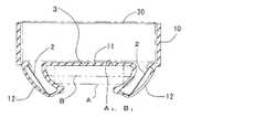
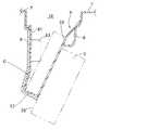
図1に本実施例に係るホルダ装置1と、非接触式の充電装置3と、携帯電話機A(電気機器)を示す分解斜視図を、図2にホルダ装置1に携帯電話機Aを収納して充電している状態の斜視図を、図3にホルダ装置の断面図を示す。このホルダ装置1は、内側形状が充電装置3の外形に対応した形状の箱状の充電装置収納部10と、充電装置収納部10の底壁11から裏面側へ突出する一対の把持突起12と、底壁11の端部に形成され一対の把持突起12による把持方向と平行に延び底壁11から突出する支持壁13と、を備え、ショアA90以下の軟質樹脂から一体に形成されている。一対の把持突起12は中空に形成され、その内部にはそれぞれ板バネ2が配置されている。 FIG. 1 is an exploded perspective view showing a
一対の把持突起12は、互いに近接する方向へ底壁10の表面に対して傾斜して突設され、板バネ2は一対の把持突起12を互いに近接する方向へ付勢している。 The pair of gripping
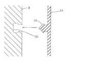
図4に拡大して示すように、把持突起12の根元には底壁11と平行に突出した後に中空部15側へ折れ曲がった舌片部16が形成されている。また板バネ2は、把持突起12の先端内周面形状に沿う形状の曲面部20と、曲面部20から延びる直線部21と、直線部21の先端から略直角に折れ曲がった係止部22とからなる。 As shown in an enlarged view in FIG. 4, a
この板バネ2を把持突起12の中空部15に保持するには、先ず曲面部20側から中空部15に挿入し、曲面部20を把持突起12の先端内周面に当接させる。次いで係止部22を舌片部16に当接させ、舌片部16の弾性変形を利用して係止部22を舌片部16の内側へ嵌入し舌片部16と係合させる。この状態で板バネ2にはバネ弾性が発生し、一対の把持突起12を互いに近接するように付勢する。 In order to hold the
このホルダ装置1は、箱状の充電装置収納部10に充電装置3が収納されることで充電装置3と一体化され、充電装置3の載置表面30が底壁11と当接している。そして図5に示すように、自動車のセンタークラスタ4に形成された凹部40に搭載されている。凹部40には、その開口を開閉可能なドア41が形成されている。もちろん、充電装置3は図示しない配線にて図示しない電源に導通されている。 The
車両乗員が携帯電話機Aを充電する際には、ドア41を開いて一対の把持突起12の間に携帯電話機Aを挿入し、携帯電話機Aの挿入端が支持壁13に当接するまで挿入する。すると一対の把持突起12は携帯電話機Aによって互いに離れる方向へ弾性変形しようとし、板バネ2には付勢力が蓄えられる。このとき図3に示すように、一対の把持突起12は、板バネ2の付勢力によって携帯電話機Aの両側面に押圧されるとともに、携帯電話機Aの充電表面A1が載置表面30に向かって押圧されている。したがって底壁11は圧縮によって厚さが薄くなり、充電表面A1と載置表面30との距離が近づくので、高い伝送効率で充電することができる。When the vehicle occupant charges the mobile phone A, the
そして携帯電話Aは、一対の把持突起12によって幅方向の移動を規制され、支持壁13によって下方への移動を規制されているので、車両の振動や加減速などによって移動することなく安定して保持され、安定した充電を行うことができる。 Since the mobile phone A is restricted in movement in the width direction by the pair of gripping
また携帯電話機Aに比べて幅広で薄型の携帯電話機Bを充電する場合でも、図3に示すように、一対の把持突起12が板バネ2の付勢力によって携帯電話機Bの両側面に押圧されるとともに、携帯電話機Bの充電表面B1が載置表面30に向かって押圧され、携帯電話機Aの場合と同様に安定した充電が可能となる。このように形状の異なる少なくとも二種の携帯電話機を安定して充電できるのは、一対の把持突起12を互いに近接する方向へ底壁10の表面に対して傾斜して突設したことによる効果である。Even when charging a mobile phone B that is wider and thinner than the mobile phone A, the pair of
なお本実施例に係るホルダ装置1は、充電装置3と一体としてあるため、車室内の別の部位にも容易に配置することができる。例えば図6に示すように、コンソールボックス5の前部に形成された凹部50に収納することができる。すなわちホルダ装置1と充電装置3とを一体とすれば、車両室内の所望の部位に容易に配置することができ、各種の車両、車種で共用することができるので、汎用性が向上し安価に提供することができる。 In addition, since the
なお図7に示すように、底壁11の一部に開口14を形成することもできる。このようにすれば、充電表面A1、B1と載置表面30とが直接対向するため障害物による抵抗が減少し、充電時の伝送効率がさらに向上する。また図8に示すように、底壁11から把持突起12と反対側へ突出する凸部17を形成し、充電装置3に形成された凹部31に嵌合させることによって、充電装置3とホルダ装置1との一体性を高めることも好ましい。In addition, as shown in FIG. 7, the
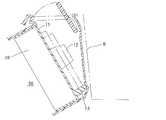
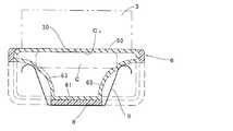
図9,10に第2の実施例に係るホルダ装置を示す。このホルダ装置6は、コンソール7の前部に形成された凹部70にポケット状に形成されている。このホルダ装置6は、底壁60と、底壁60と対向する対向壁61と、底壁60の下端と対向壁61の下端とを連結する支持壁62とを有し、実施例1と同じ材料から容器形状に一体に形成されている。対向壁61には、断面円弧状の一対の把持突起63が突設されている。一対の把持突起63は中空状に形成され、その内部に配置された板バネ9が一対の把持突起63を互いに近接する方向へ、かつ底壁60へ近接する方向へ付勢している。 9 and 10 show a holder device according to the second embodiment. The holder device 6 is formed in a pocket shape in a
底壁60は、コンソール7に予め固定された充電装置3の載置表面30に当接して保持されている。そして底壁60の、載置表面30に当接している部分及び把持突起63を除く全壁面には、硬質樹脂からなる裏打板8が積層され、形状補強がなされている。対向壁61及び底壁60の上端はそれぞれコンソール7に保持固定されている。 The
本実施例のホルダ装置を用いて車両乗員が携帯電話機Cを充電する際には、一対の把持突起63と底壁60との間に携帯電話Cを挿入し、携帯電話機Cの挿入端が支持壁62に当接するまで挿入する。すると一対の把持突起63は携帯電話機Cによって互いに離れる方向へ弾性変形し、板バネ7には付勢力が蓄えられる。このとき一対の把持突起63は、板バネ9の付勢力によって携帯電話機Cの両側面のコーナー部を押圧するとともに、携帯電話機Cを載置表面30に向かって押圧している。したがって底壁60は圧縮によって厚さが薄くなり、携帯電話機Cの充電表面C1と載置表面30との距離が近づくので、高い伝送効率で充電することができる。When the vehicle occupant charges the mobile phone C using the holder device of this embodiment, the mobile phone C is inserted between the pair of
そして携帯電話機Cは、一対の把持突起63によって幅方向の移動を規制され、支持壁62によって下方への移動を規制されているので、車両の振動や加減速などによって移動することなく安定して保持され、安定した充電を行うことができる。また板バネ9は、携帯電話機Cの充電表面C1と反対側の表面に向かって把持突起63を押圧するので、板バネ9と載置表面30との距離を大きく取ることができる。したがって金属製の板バネ9を用いても、充電装置3の誤作動を防止することができる。Since the mobile phone C is restricted from moving in the width direction by the pair of gripping
上記の実施例では車載用の用途を説明したが、本発明の充電式電気機器用ホルダ装置は、列車、船舶、飛行機など各種乗り物ばかりか、工場など振動が大きな場所における電気機器の充電に用いることができる。 In the above-described embodiment, the use for in-vehicle use has been described. However, the holder device for rechargeable electric equipment according to the present invention is used for charging electric equipment not only in various vehicles such as trains, ships, airplanes, etc., but also in places with large vibrations such as factories. be able to.
1,6:ホルダ装置 2,9:板バネ(付勢部材) 3:非接触式充電装置
11,60:底壁 12,63:把持突起 13,62:支持壁
14:開口 61:対向壁 A,B,C:充電式電気機器
30:載置表面 A1,B1,C1:充電表面DESCRIPTION OF
Claims (6)
Translated fromJapanese該載置表面に少なくとも一部が当接し該載置表面と該充電表面との間に介在する底壁と、該底壁及び該底壁と対向する対向壁の少なくとも一方から突出し該充電式電気機器を両側から把持する少なくとも一対の把持突起と、一対の該把持突起を互いに近接する方向へ付勢する付勢部材と、を有し、
少なくとも一対の該把持突起はショアA90以下の軟質材から形成され、充電時には、一対の該把持突起は該付勢部材の付勢によって該充電式電気機器を把持するとともに該充電表面が該載置表面に向かって押圧されることを特徴とする充電式電気機器用ホルダ装置。At the time of charging, a holder device in which the rechargeable electric device is accommodated so that the mounting surface of the non-contact charging device and the charging surface of the rechargeable electric device face each other directly or indirectly,
The rechargeable electricity projecting from at least one of a bottom wall that is at least partially in contact with the mounting surface and interposed between the mounting surface and the charging surface, and a bottom wall and an opposing wall facing the bottom wall Having at least a pair of gripping projections for gripping the device from both sides, and a biasing member for biasing the pair of gripping projections in a direction approaching each other,
At least a pair of the gripping protrusions is formed of a soft material of Shore A 90 or less, and at the time of charging, the pair of gripping protrusions grips the rechargeable electric device by the biasing of the biasing member and the charging surface is placed on the mounting surface. A holder device for a rechargeable electric device, wherein the holder device is pressed toward a surface.
Priority Applications (1)
| Application Number | Priority Date | Filing Date | Title |
|---|---|---|---|
| JP2011234559AJP2013093973A (en) | 2011-10-26 | 2011-10-26 | Holder device for charging type electric apparatus |
Applications Claiming Priority (1)
| Application Number | Priority Date | Filing Date | Title |
|---|---|---|---|
| JP2011234559AJP2013093973A (en) | 2011-10-26 | 2011-10-26 | Holder device for charging type electric apparatus |
Publications (1)
| Publication Number | Publication Date |
|---|---|
| JP2013093973Atrue JP2013093973A (en) | 2013-05-16 |
Family
ID=48616660
Family Applications (1)
| Application Number | Title | Priority Date | Filing Date |
|---|---|---|---|
| JP2011234559APendingJP2013093973A (en) | 2011-10-26 | 2011-10-26 | Holder device for charging type electric apparatus |
Country Status (1)
| Country | Link |
|---|---|
| JP (1) | JP2013093973A (en) |
Cited By (10)
| Publication number | Priority date | Publication date | Assignee | Title |
|---|---|---|---|---|
| KR100852066B1 (en)* | 2002-03-06 | 2008-08-13 | 후지쯔 가부시끼가이샤 | Wiring-inclusive structure and forming method thereof |
| KR20190106356A (en)* | 2018-03-09 | 2019-09-18 | 김현학 | Holder for electric label |
| JP2021087323A (en)* | 2019-11-29 | 2021-06-03 | 豊田合成株式会社 | Wireless power supply holder |
| JP2021088259A (en)* | 2019-12-04 | 2021-06-10 | 豊田合成株式会社 | Wireless power feeding holder |
| JP2021093809A (en)* | 2019-12-09 | 2021-06-17 | 豊田合成株式会社 | Wireless power supply case |
| FR3106793A1 (en)* | 2020-02-03 | 2021-08-06 | Renault S.A.S | vehicle equipped with an electronic object recharging system |
| JP2021133830A (en)* | 2020-02-27 | 2021-09-13 | 豊田合成株式会社 | Wireless power supply holder |
| JP2022512334A (en)* | 2018-12-04 | 2022-02-03 | ターガス インターナショナル エルエルシー | Wireless charging holster for portable electronic devices |
| DE102022110371A1 (en) | 2021-04-29 | 2022-11-03 | Tdk Corporation | COIL MODULE AND WIRELESS POWER TRANSFER DEVICE |
| JP2024022885A (en)* | 2022-08-08 | 2024-02-21 | 豊田合成株式会社 | Vehicle storage device |
- 2011
- 2011-10-26JPJP2011234559Apatent/JP2013093973A/enactivePending
Cited By (17)
| Publication number | Priority date | Publication date | Assignee | Title |
|---|---|---|---|---|
| KR100852066B1 (en)* | 2002-03-06 | 2008-08-13 | 후지쯔 가부시끼가이샤 | Wiring-inclusive structure and forming method thereof |
| KR20190106356A (en)* | 2018-03-09 | 2019-09-18 | 김현학 | Holder for electric label |
| KR102067492B1 (en) | 2018-03-09 | 2020-01-17 | 김현학 | Holder for electric label |
| JP2022512334A (en)* | 2018-12-04 | 2022-02-03 | ターガス インターナショナル エルエルシー | Wireless charging holster for portable electronic devices |
| JP7247869B2 (en) | 2019-11-29 | 2023-03-29 | 豊田合成株式会社 | Wireless power supply holder |
| JP2021087323A (en)* | 2019-11-29 | 2021-06-03 | 豊田合成株式会社 | Wireless power supply holder |
| JP2021088259A (en)* | 2019-12-04 | 2021-06-10 | 豊田合成株式会社 | Wireless power feeding holder |
| JP7354809B2 (en) | 2019-12-04 | 2023-10-03 | 豊田合成株式会社 | wireless power holder |
| JP2021093809A (en)* | 2019-12-09 | 2021-06-17 | 豊田合成株式会社 | Wireless power supply case |
| JP7207282B2 (en) | 2019-12-09 | 2023-01-18 | 豊田合成株式会社 | Wireless power supply case |
| FR3106793A1 (en)* | 2020-02-03 | 2021-08-06 | Renault S.A.S | vehicle equipped with an electronic object recharging system |
| JP2021133830A (en)* | 2020-02-27 | 2021-09-13 | 豊田合成株式会社 | Wireless power supply holder |
| DE102022110371A1 (en) | 2021-04-29 | 2022-11-03 | Tdk Corporation | COIL MODULE AND WIRELESS POWER TRANSFER DEVICE |
| JP2022170747A (en)* | 2021-04-29 | 2022-11-11 | Tdk株式会社 | Coil module and wireless power transmission device |
| JP7713803B2 (en) | 2021-04-29 | 2025-07-28 | Tdk株式会社 | Coil module and wireless power transmission device |
| JP2024022885A (en)* | 2022-08-08 | 2024-02-21 | 豊田合成株式会社 | Vehicle storage device |
| JP7718349B2 (en) | 2022-08-08 | 2025-08-05 | 豊田合成株式会社 | Vehicle storage device |
Similar Documents
| Publication | Publication Date | Title |
|---|---|---|
| JP2013093973A (en) | Holder device for charging type electric apparatus | |
| JP6246483B2 (en) | Battery pack for electric tools | |
| JP6091968B2 (en) | Battery pack for electric tools | |
| RU2475894C2 (en) | Storage battery and manual battery-driven machine using it | |
| CN113424390B (en) | Electronic device and charger kit and communication system | |
| JP6133103B2 (en) | Battery pack for electric tools | |
| JP7617457B2 (en) | Vehicle seats | |
| JP6169594B2 (en) | Power transmitter device for inductively supplying power to mobile devices | |
| KR20160146478A (en) | Wireless charging device for vehicle | |
| KR101435678B1 (en) | Battery charging device and battery with the same | |
| JP2013004341A (en) | Power storage device and spacer | |
| CN115136403B (en) | Battery pack, energy storage system and vehicle | |
| CN103958132B (en) | Casing for a hand-held tool | |
| US10374268B2 (en) | Battery module | |
| KR20180061775A (en) | Connecting device for charging electricity and electric car | |
| AU2018307527B2 (en) | Battery pack and production method for same | |
| JP2014038720A (en) | Battery pack | |
| KR102647877B1 (en) | Plug device for charging electricity | |
| KR101709869B1 (en) | Wireless charging device for vehicle | |
| JP7283419B2 (en) | Wireless power supply holder | |
| JP2005347900A (en) | Charger for mobile phone | |
| TWI886563B (en) | Smart key charging device | |
| KR101947005B1 (en) | Battery charging device for electric tool | |
| KR20150025024A (en) | Electronic device having battery pack receptacle | |
| JP3896122B2 (en) | Holder for charging mobile communication device |