JP2013091451A - Lighting equipment for vehicle - Google Patents
Lighting equipment for vehicleDownload PDFInfo
- Publication number
- JP2013091451A JP2013091451AJP2011235382AJP2011235382AJP2013091451AJP 2013091451 AJP2013091451 AJP 2013091451AJP 2011235382 AJP2011235382 AJP 2011235382AJP 2011235382 AJP2011235382 AJP 2011235382AJP 2013091451 AJP2013091451 AJP 2013091451A
- Authority
- JP
- Japan
- Prior art keywords
- light
- vehicle
- resin
- interior material
- finisher
- Prior art date
- Legal status (The legal status is an assumption and is not a legal conclusion. Google has not performed a legal analysis and makes no representation as to the accuracy of the status listed.)
- Granted
Links
- 239000011347resinSubstances0.000claimsabstractdescription24
- 229920005989resinPolymers0.000claimsabstractdescription24
- 239000000463materialSubstances0.000claimsabstractdescription21
- 238000004381surface treatmentMethods0.000claimsdescription14
- 238000005286illuminationMethods0.000claimsdescription10
- 238000010422paintingMethods0.000claimsdescription7
- 238000007747platingMethods0.000claimsdescription7
- 238000007639printingMethods0.000claimsdescription7
- 230000003287optical effectEffects0.000abstract2
- 239000011162core materialSubstances0.000description3
- 239000011248coating agentSubstances0.000description2
- 238000000576coating methodMethods0.000description2
- 230000000694effectsEffects0.000description2
- 239000000758substrateSubstances0.000description2
- 239000004925Acrylic resinSubstances0.000description1
- 229920000178Acrylic resinPolymers0.000description1
- 238000004519manufacturing processMethods0.000description1
- 238000012986modificationMethods0.000description1
- 230000004048modificationEffects0.000description1
- 230000001105regulatory effectEffects0.000description1
Images


Landscapes
- Vehicle Interior And Exterior Ornaments, Soundproofing, And Insulation (AREA)
- Arrangements Of Lighting Devices For Vehicle Interiors, Mounting And Supporting Thereof, Circuits Therefore (AREA)
Abstract
Description
Translated fromJapanese本発明は、車両の内装材に設けて、夜間照明時に車両内で点灯させる車両用照明装置に関する。 The present invention relates to a vehicular illumination device that is provided in an interior material of a vehicle and is lit in a vehicle during night illumination.
従来より、ドアトリム、リヤサイドトリム、ラゲージトリム、インストルメントパネル等、内装トリム部品に照明装置を取り付けて、昼間のトリム表面の柄模様と、夜間照明時におけるトリム表面の柄模様との顕著な相違による演出効果で乗員にサプライズ感を付与する車両用照明装置が知られている(例えば、特許文献1参照)。 Conventionally, lighting devices are attached to interior trim parts such as door trims, rear side trims, luggage trims, instrument panels, etc. Due to the marked difference between the pattern pattern on the trim surface during daytime and the pattern on the trim surface during night illumination. 2. Description of the Related Art A vehicular lighting device that gives a sense of surprise to an occupant with a production effect is known (see, for example, Patent Document 1).
図4に示すように、特許文献1に記載の車両用照明装置100は、上下二分割構造のドアトリム101に設けられている。ドアトリム101は、アッパートリム本体102を有するドアトリムアッパー101Aと、ロアトリム本体103を有するドアトリムロア101Bからなる。アッパートリム本体102は、透光性を有する芯材107と、この芯材107の表面に貼着され、透光性を有する表皮材108とから構成される。 As shown in FIG. 4, the
ドアトリムアッパー101Aおよびドアトリムロア101Bの背面側には、各々照明ユニット104が設けられている。照明ユニット104は、透明アクリル樹脂板からなる導光板105と、この導光板105に照明光を供給する光源としての複数のLED106を有する。
これにより、夜間照明時に照明ユニット104を点灯させることにより導光板105が発光し、光が芯材107および表皮材108を透過して、ドアトリム101の外観表面に昼間(非照明時)とは明らかに相違する柄模様を現出させることができる。
As a result, the
しかしながら、前述した特許文献1に記載の車両用照明装置では、面状に発光させるには、光源であるLEDからの光を広げる導光体を別途用いる必要があり、部品点数の増加、コストアップ、組み立て工数の増加等をまねくという問題がある。 However, in the vehicle lighting device described in Patent Document 1 described above, in order to emit light in a planar shape, it is necessary to separately use a light guide that spreads light from the LED that is the light source, which increases the number of components and increases the cost. There is a problem of increasing the number of assembly steps.
そこで、本発明は、上記問題点を解決するために、部品点数の増加やコストの増加を抑えて、車両用内装材を面状に発光させることができる車両用照明装置を提供することにある。 SUMMARY OF THE INVENTION In order to solve the above problems, the present invention is to provide a vehicular illumination device capable of emitting a vehicular interior material in a planar shape while suppressing an increase in the number of parts and an increase in cost. .
上記課題を解決するために、本発明に係る車両用照明装置は、車両用内装材を発光させる車両用照明装置であって、発光させる前記車両用内装材を透光性の樹脂で形成し、前記樹脂の少なくとも一端面に光源を対向配置したものである。 In order to solve the above problems, a vehicle lighting device according to the present invention is a vehicle lighting device that emits light from a vehicle interior material, and the vehicle interior material that emits light is formed of a translucent resin. A light source is disposed opposite to at least one end surface of the resin.
この構成によれば、車両用内装材を透明あるいは半透明の透光性を有する樹脂で形成し、樹脂の少なくとも一端面に対向して光源を配置したので、光源からの光は、車両用内装材である樹脂を導光体として光が伝達され、面状に発光する。
これにより、従来のように導光体を別個に設ける必要がないため、部品点数の増加やコストの増加を抑えて、車両用内装材を面状に発光させることができる。また、既存の部品を用いるので、組み立て工数が増加しない。According to this configuration, the vehicle interior material is formed of a transparent or translucent resin having translucency, and the light source is disposed so as to face at least one end surface of the resin. Light is transmitted using a resin, which is a material, as a light guide, and light is emitted in a planar shape.
Thereby, since it is not necessary to provide a light guide separately as in the prior art, it is possible to suppress the increase in the number of parts and the cost and to cause the vehicle interior material to emit light in a planar shape. In addition, since existing parts are used, the number of assembly steps does not increase.
上記構成において、前記樹脂の表面であって発光させない部位には遮光の表面処理を行うものである。 In the above configuration, the surface of the resin that does not emit light is subjected to a light-shielding surface treatment.
この構成によれば、樹脂の表面に、任意の模様等を付して遮光することにより、発光部分の形状等を規制することができる。 According to this configuration, it is possible to regulate the shape or the like of the light emitting portion by providing an arbitrary pattern or the like on the surface of the resin to shield it from light.
上記構成において、前記表面処理が、塗装、印刷、メッキであるものである。 In the above configuration, the surface treatment is painting, printing, or plating.
この構成によれば、樹脂の表面に遮光のために施す表面処理として、塗装、印刷、メッキ等を用いることができる。
なお、塗装、印刷、メッキの厚さを調整することにより、全体を薄くぼんやりと発光させることもできる。According to this configuration, coating, printing, plating, or the like can be used as the surface treatment applied to the resin surface for light shielding.
By adjusting the thickness of painting, printing, and plating, the whole can be thinly and lightly emitted.
上記構成において、前記発光させない部位が模様であるものである。 The said structure WHEREIN: The site | part which is not made to light-emit is a pattern.
この構成によれば、樹脂の表面に、表面処理を施して模様を形成することができるので、光源を発光させることにより、模様を浮き上がらせて表示することができる。 According to this configuration, the surface of the resin can be subjected to a surface treatment to form a pattern, so that the pattern can be lifted and displayed by causing the light source to emit light.
本発明によれば、車両用内装材を透明あるいは半透明の透光性を有する樹脂で形成し、樹脂の少なくとも一端面に対向して光源を配置したので、光源からの光は、車両用内装材である樹脂を導光体として光が伝達され、面状に発光する。これにより、従来のように導光体を別個に設ける必要がないため、部品点数の増加やコストの増加を抑えて、車両用内装材を面状に発光させることができる。また、既存の部品を用いるので、組み立て工数が増加しないという効果がある。 According to the present invention, the vehicle interior material is formed of a transparent or translucent resin having translucency, and the light source is disposed opposite to at least one end surface of the resin. Light is transmitted using a resin, which is a material, as a light guide, and light is emitted in a planar shape. Thereby, since it is not necessary to provide a light guide separately as in the prior art, it is possible to suppress the increase in the number of parts and the cost and to cause the vehicle interior material to emit light in a planar shape. In addition, since existing parts are used, there is an effect that the number of assembling steps does not increase.
以下、添付図面を参照して、本発明を実施するための形態(以下、実施形態)について詳細に説明する。なお、実施形態の説明の全体を通して同じ要素には同じ番号を付している。 DESCRIPTION OF EMBODIMENTS Hereinafter, embodiments for carrying out the present invention (hereinafter referred to as embodiments) will be described in detail with reference to the accompanying drawings. Note that the same number is assigned to the same element throughout the description of the embodiment.
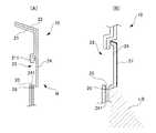
図1に示すように、本発明にかかる車両用照明装置10は、例えば、ドアトリム20に適用することができる。
ドアトリム20は、ドアベース21の上に、車室内の意匠性を考慮した樹脂製の表皮材22が貼り付けられている。この表皮材22は、透光性を有しない。
ドアベース21には、高さ方向中央部に開口23が設けられており、開口23の上下に垂直に延びる鍔部211、212が設けられている。開口23は発光させる車両用内装材であるフィニッシャ(加飾部品)24により覆われる。フィニッシャ24は、透明あるいは半透明の透光性を有する樹脂で形成されており、上下の鍔部211,212に当接して取り付けられる。As shown in FIG. 1, the
In the
The
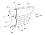
図2(A)および(B)に示すように、フィニッシャ24の一端面である下端面241に対向して、光源であるLED25が設けられている。LED25は基板26に複数個実装されており、下端面241の長手方向に沿って対向配置されている。
なお、ここでは、フィニッシャ24の下端面241に対向してLED25および基板26を設けたが、このほか、フィニッシャ24の上端面や側端面に対向して設けることも可能である。あるいは、上下端面や側端面を組み合わせて設けることも可能である。As shown in FIGS. 2A and 2B, an
Here, the
フィニッシャ24の発光させない部位には、表面に遮光の表面処理を行う。遮光の表面処理としては、例えば、図2(B)に示すように、フィニッシャ24の表面に、遮光性のある塗装27、印刷、メッキ等を施す。ここでは、フィニッシャ24において遮光の表面処理(塗装)を行っていない下部242から光LBが漏れて下方を照明する。
また、フィニッシャ24に、遮光の表面処理によって模様や文字等を形成することにより、文字や、模様を浮き上がらせることができる。The surface of the
Further, by forming a pattern, a character, or the like on the
以上説明したことから明らかとなるように、本発明にかかる車両用照明装置10によれば、フィニッシャ24を透明あるいは半透明の透光性を有する樹脂で形成し、樹脂の下端面241に対向してLED25を配置したので、LED25からの光LBは、フィニッシャ24である樹脂を導光体として光が伝達され、面状に発光する。
これにより、従来のように導光体を別個に設ける必要がないため、部品点数の増加やコストの増加を抑えて、フィニッシャ24を面状に発光させることができる。また、既存の部品を用いるので、組み立て工数が増加しない。As will be apparent from the above description, according to the
Thereby, since it is not necessary to provide a light guide separately as in the prior art, the
また、フィニッシャ24の表面に、任意の模様等を付して遮光することにより、発光部分の形状等を規制することができる。 Further, the shape or the like of the light emitting portion can be regulated by providing an arbitrary pattern or the like on the surface of the
また、フィニッシャ24の表面に遮光のために施す表面処理として、塗装、印刷、メッキ等を用いることができる。
なお、塗装、印刷、メッキの厚さを調整することにより、全体を薄くぼんやりと発光させることもできる。Further, as the surface treatment applied to the surface of the
By adjusting the thickness of painting, printing, and plating, the whole can be thinly and lightly emitted.
さらに、フィニッシャ24の表面に、表面処理を施して模様を形成することができるので、LED25を発光させることにより、模様を浮き上がらせて表示することができる。 Furthermore, since the surface of the
以上、実施形態を用いて本発明を説明したが、本発明の技術的範囲は上記実施形態に記載の範囲には限定されないことは言うまでもない。上記実施形態に、多様な変更または改良を加えることが可能であることが当業者に明らかである。またその様な変更または改良を加えた形態も本発明の技術的範囲に含まれ得ることが、特許請求の範囲の記載から明らかである。
例えば、前述した実施形態においては、ドアトリム20のフィニッシャ24に本発明に係る車両用照明装置10を設けた場合を例示したが、これに限るものではない。その他の部位、例えば、パワーウインドウスイッチのフィニッシャや、ドアグリップキャップ等にも適用可能である。As mentioned above, although this invention was demonstrated using embodiment, it cannot be overemphasized that the technical scope of this invention is not limited to the range as described in the said embodiment. It will be apparent to those skilled in the art that various modifications or improvements can be added to the above-described embodiments. Further, it is apparent from the scope of the claims that the embodiments added with such changes or improvements can be included in the technical scope of the present invention.
For example, in the above-described embodiment, the case where the
また、前述した実施形態においては、遮光の表面処理として、フィニッシャ24の表面に塗装やメッキを施す場合を例示したが、図3に示すように、透光性の樹脂(下部242)と遮光性の樹脂28を用いてフィニッシャ24Bを一体成型する車両用照明装置10Bも可能である。 In the above-described embodiment, the case where the surface of the
10,10B 車両用照明装置
24 フィニッシャ(車両用内装材)
241 下端面(一端面)
25 LED(光源)
27 塗装(表面処理)10, 10B
241 Lower end surface (one end surface)
25 LED (light source)
27 Painting (surface treatment)
Claims (4)
Translated fromJapanese発光させる前記車両用内装材を透光性の樹脂で形成し、
前記樹脂の少なくとも一端面に光源を対向配置したことを特徴とする車両用照明装置。A vehicle lighting device that emits light from a vehicle interior material,
Forming the vehicle interior material to emit light with a translucent resin;
A vehicle lighting device, wherein a light source is disposed opposite to at least one end surface of the resin.
Priority Applications (1)
| Application Number | Priority Date | Filing Date | Title |
|---|---|---|---|
| JP2011235382AJP5578476B2 (en) | 2011-10-26 | 2011-10-26 | Vehicle lighting device |
Applications Claiming Priority (1)
| Application Number | Priority Date | Filing Date | Title |
|---|---|---|---|
| JP2011235382AJP5578476B2 (en) | 2011-10-26 | 2011-10-26 | Vehicle lighting device |
Publications (2)
| Publication Number | Publication Date |
|---|---|
| JP2013091451Atrue JP2013091451A (en) | 2013-05-16 |
| JP5578476B2 JP5578476B2 (en) | 2014-08-27 |
Family
ID=48614920
Family Applications (1)
| Application Number | Title | Priority Date | Filing Date |
|---|---|---|---|
| JP2011235382AExpired - Fee RelatedJP5578476B2 (en) | 2011-10-26 | 2011-10-26 | Vehicle lighting device |
Country Status (1)
| Country | Link |
|---|---|
| JP (1) | JP5578476B2 (en) |
Cited By (4)
| Publication number | Priority date | Publication date | Assignee | Title |
|---|---|---|---|---|
| JP2016221988A (en)* | 2015-05-27 | 2016-12-28 | トヨタ紡織株式会社 | Interior materials for vehicles |
| DE102015013669A1 (en)* | 2015-10-23 | 2017-04-27 | Lisa Dräxlmaier GmbH | Backlit interior part for a motor vehicle |
| JP2017109710A (en)* | 2015-12-18 | 2017-06-22 | 大日本印刷株式会社 | Lighting device |
| WO2017145388A1 (en)* | 2016-02-26 | 2017-08-31 | 河西工業株式会社 | Vehicle interior component and light guide plate |
Citations (6)
| Publication number | Priority date | Publication date | Assignee | Title |
|---|---|---|---|---|
| JP2000285766A (en)* | 1999-03-30 | 2000-10-13 | Nippon Seiki Co Ltd | Control unit |
| JP2007030774A (en)* | 2005-07-28 | 2007-02-08 | Toyoda Gosei Co Ltd | Vehicle interior lighting device |
| JP2008001130A (en)* | 2006-06-20 | 2008-01-10 | Toyota Boshoku Corp | Vehicle interior lighting device |
| JP2009101840A (en)* | 2007-10-23 | 2009-05-14 | Kasai Kogyo Co Ltd | Vehicle lighting device |
| JP2009262821A (en)* | 2008-04-25 | 2009-11-12 | Harison Toshiba Lighting Corp | Stay for in-vehicle sun visor, and sun visor unit |
| JP2010030336A (en)* | 2008-07-25 | 2010-02-12 | Toyoda Gosei Co Ltd | Vehicular lighting system |
- 2011
- 2011-10-26JPJP2011235382Apatent/JP5578476B2/ennot_activeExpired - Fee Related
Patent Citations (6)
| Publication number | Priority date | Publication date | Assignee | Title |
|---|---|---|---|---|
| JP2000285766A (en)* | 1999-03-30 | 2000-10-13 | Nippon Seiki Co Ltd | Control unit |
| JP2007030774A (en)* | 2005-07-28 | 2007-02-08 | Toyoda Gosei Co Ltd | Vehicle interior lighting device |
| JP2008001130A (en)* | 2006-06-20 | 2008-01-10 | Toyota Boshoku Corp | Vehicle interior lighting device |
| JP2009101840A (en)* | 2007-10-23 | 2009-05-14 | Kasai Kogyo Co Ltd | Vehicle lighting device |
| JP2009262821A (en)* | 2008-04-25 | 2009-11-12 | Harison Toshiba Lighting Corp | Stay for in-vehicle sun visor, and sun visor unit |
| JP2010030336A (en)* | 2008-07-25 | 2010-02-12 | Toyoda Gosei Co Ltd | Vehicular lighting system |
Cited By (5)
| Publication number | Priority date | Publication date | Assignee | Title |
|---|---|---|---|---|
| JP2016221988A (en)* | 2015-05-27 | 2016-12-28 | トヨタ紡織株式会社 | Interior materials for vehicles |
| DE102015013669A1 (en)* | 2015-10-23 | 2017-04-27 | Lisa Dräxlmaier GmbH | Backlit interior part for a motor vehicle |
| DE102015013669B4 (en) | 2015-10-23 | 2023-02-09 | Lisa Dräxlmaier GmbH | Backlit interior trim part for a motor vehicle |
| JP2017109710A (en)* | 2015-12-18 | 2017-06-22 | 大日本印刷株式会社 | Lighting device |
| WO2017145388A1 (en)* | 2016-02-26 | 2017-08-31 | 河西工業株式会社 | Vehicle interior component and light guide plate |
Also Published As
| Publication number | Publication date |
|---|---|
| JP5578476B2 (en) | 2014-08-27 |
Similar Documents
| Publication | Publication Date | Title |
|---|---|---|
| JP5282133B2 (en) | Vehicle lighting device | |
| RU116813U1 (en) | VEHICLE INTERIOR PANEL | |
| JP2009248617A (en) | Scuff plate | |
| WO2016035502A1 (en) | Illumination device | |
| JP2014231311A (en) | Vehicle use decorative component | |
| WO2012049946A1 (en) | Planar light-emitting device | |
| JP5578476B2 (en) | Vehicle lighting device | |
| JP2015003627A (en) | Interior material for vehicle | |
| JP6285644B2 (en) | Decorative parts for vehicles and linings for vehicles | |
| JP2014094656A (en) | Decorative illumination device | |
| JP4949051B2 (en) | Vehicle lighting device | |
| JP7235957B2 (en) | Vehicle decorative parts, vehicle linings and vehicle doors | |
| US20160016510A1 (en) | Light guide film applied at instrument cluster | |
| JP2014040194A (en) | Lighting device of vehicle | |
| JP4760808B2 (en) | Interior lighting device for vehicle and interior lighting structure for vehicle | |
| CN214929453U (en) | Can luminous sign in different region | |
| JP2008174133A (en) | Vehicle interior lighting device | |
| JP6246899B2 (en) | Decorative lighting structure | |
| JP2008162296A (en) | Vehicle lighting | |
| JP2024050116A (en) | Lighting equipment | |
| JP2013244894A (en) | Interior material for vehicle | |
| JP6635509B2 (en) | Illuminated vehicle door handle protector and its lighting structure | |
| JP6973273B2 (en) | Lighting equipment for vehicles | |
| US20160107567A1 (en) | Instrument cluster including a pcb mounted light conductor | |
| CN202065775U (en) | Multi-effect lamps |
Legal Events
| Date | Code | Title | Description |
|---|---|---|---|
| A621 | Written request for application examination | Free format text:JAPANESE INTERMEDIATE CODE: A621 Effective date:20130830 | |
| A977 | Report on retrieval | Free format text:JAPANESE INTERMEDIATE CODE: A971007 Effective date:20140310 | |
| A131 | Notification of reasons for refusal | Free format text:JAPANESE INTERMEDIATE CODE: A131 Effective date:20140318 | |
| A521 | Request for written amendment filed | Free format text:JAPANESE INTERMEDIATE CODE: A523 Effective date:20140513 | |
| TRDD | Decision of grant or rejection written | ||
| A01 | Written decision to grant a patent or to grant a registration (utility model) | Free format text:JAPANESE INTERMEDIATE CODE: A01 Effective date:20140603 | |
| A61 | First payment of annual fees (during grant procedure) | Free format text:JAPANESE INTERMEDIATE CODE: A61 Effective date:20140627 | |
| R150 | Certificate of patent or registration of utility model | Ref document number:5578476 Country of ref document:JP Free format text:JAPANESE INTERMEDIATE CODE: R150 | |
| LAPS | Cancellation because of no payment of annual fees |