JP2013088866A - Electric vehicle charging system - Google Patents
Electric vehicle charging systemDownload PDFInfo
- Publication number
- JP2013088866A JP2013088866AJP2011225988AJP2011225988AJP2013088866AJP 2013088866 AJP2013088866 AJP 2013088866AJP 2011225988 AJP2011225988 AJP 2011225988AJP 2011225988 AJP2011225988 AJP 2011225988AJP 2013088866 AJP2013088866 AJP 2013088866A
- Authority
- JP
- Japan
- Prior art keywords
- charging
- power supply
- service
- electric vehicle
- power
- Prior art date
- Legal status (The legal status is an assumption and is not a legal conclusion. Google has not performed a legal analysis and makes no representation as to the accuracy of the status listed.)
- Pending
Links
- 238000007600chargingMethods0.000titleclaimsabstractdescription417
- 238000012545processingMethods0.000description44
- 238000000034methodMethods0.000description37
- 230000008569processEffects0.000description29
- 230000006399behaviorEffects0.000description10
- 238000005457optimizationMethods0.000description8
- 230000007704transitionEffects0.000description7
- 238000004891communicationMethods0.000description4
- 238000001514detection methodMethods0.000description4
- 230000006870functionEffects0.000description4
- 230000004044responseEffects0.000description4
- 230000008859changeEffects0.000description3
- 230000003111delayed effectEffects0.000description3
- 230000009467reductionEffects0.000description3
- 125000002066L-histidyl groupChemical group[H]N1C([H])=NC(C([H])([H])[C@](C(=O)[*])([H])N([H])[H])=C1[H]0.000description2
- 230000002238attenuated effectEffects0.000description2
- 238000006243chemical reactionMethods0.000description2
- 238000012937correctionMethods0.000description2
- 230000007423decreaseEffects0.000description2
- 230000005611electricityEffects0.000description2
- 238000007726management methodMethods0.000description2
- 230000001343mnemonic effectEffects0.000description2
- 238000011084recoveryMethods0.000description2
- 230000001932seasonal effectEffects0.000description2
- XLYOFNOQVPJJNP-UHFFFAOYSA-NwaterSubstancesOXLYOFNOQVPJJNP-UHFFFAOYSA-N0.000description2
- KNMAVSAGTYIFJF-UHFFFAOYSA-N1-[2-[(2-hydroxy-3-phenoxypropyl)amino]ethylamino]-3-phenoxypropan-2-ol;dihydrochlorideChemical compoundCl.Cl.C=1C=CC=CC=1OCC(O)CNCCNCC(O)COC1=CC=CC=C1KNMAVSAGTYIFJF-UHFFFAOYSA-N0.000description1
- 238000009825accumulationMethods0.000description1
- 238000004458analytical methodMethods0.000description1
- 238000013459approachMethods0.000description1
- 238000004364calculation methodMethods0.000description1
- 239000003990capacitorSubstances0.000description1
- 230000015556catabolic processEffects0.000description1
- 230000007812deficiencyEffects0.000description1
- 238000010586diagramMethods0.000description1
- 238000007599dischargingMethods0.000description1
- 238000005516engineering processMethods0.000description1
- 238000009434installationMethods0.000description1
- 230000001404mediated effectEffects0.000description1
- 230000002093peripheral effectEffects0.000description1
- 238000010278pulse chargingMethods0.000description1
- 239000004065semiconductorSubstances0.000description1
- 238000010792warmingMethods0.000description1
Images


Classifications
- B—PERFORMING OPERATIONS; TRANSPORTING
- B60—VEHICLES IN GENERAL
- B60L—PROPULSION OF ELECTRICALLY-PROPELLED VEHICLES; SUPPLYING ELECTRIC POWER FOR AUXILIARY EQUIPMENT OF ELECTRICALLY-PROPELLED VEHICLES; ELECTRODYNAMIC BRAKE SYSTEMS FOR VEHICLES IN GENERAL; MAGNETIC SUSPENSION OR LEVITATION FOR VEHICLES; MONITORING OPERATING VARIABLES OF ELECTRICALLY-PROPELLED VEHICLES; ELECTRIC SAFETY DEVICES FOR ELECTRICALLY-PROPELLED VEHICLES
- B60L53/00—Methods of charging batteries, specially adapted for electric vehicles; Charging stations or on-board charging equipment therefor; Exchange of energy storage elements in electric vehicles
- B60L53/10—Methods of charging batteries, specially adapted for electric vehicles; Charging stations or on-board charging equipment therefor; Exchange of energy storage elements in electric vehicles characterised by the energy transfer between the charging station and the vehicle
- B60L53/14—Conductive energy transfer
- B—PERFORMING OPERATIONS; TRANSPORTING
- B60—VEHICLES IN GENERAL
- B60L—PROPULSION OF ELECTRICALLY-PROPELLED VEHICLES; SUPPLYING ELECTRIC POWER FOR AUXILIARY EQUIPMENT OF ELECTRICALLY-PROPELLED VEHICLES; ELECTRODYNAMIC BRAKE SYSTEMS FOR VEHICLES IN GENERAL; MAGNETIC SUSPENSION OR LEVITATION FOR VEHICLES; MONITORING OPERATING VARIABLES OF ELECTRICALLY-PROPELLED VEHICLES; ELECTRIC SAFETY DEVICES FOR ELECTRICALLY-PROPELLED VEHICLES
- B60L53/00—Methods of charging batteries, specially adapted for electric vehicles; Charging stations or on-board charging equipment therefor; Exchange of energy storage elements in electric vehicles
- B60L53/10—Methods of charging batteries, specially adapted for electric vehicles; Charging stations or on-board charging equipment therefor; Exchange of energy storage elements in electric vehicles characterised by the energy transfer between the charging station and the vehicle
- B60L53/11—DC charging controlled by the charging station, e.g. mode 4
- B—PERFORMING OPERATIONS; TRANSPORTING
- B60—VEHICLES IN GENERAL
- B60L—PROPULSION OF ELECTRICALLY-PROPELLED VEHICLES; SUPPLYING ELECTRIC POWER FOR AUXILIARY EQUIPMENT OF ELECTRICALLY-PROPELLED VEHICLES; ELECTRODYNAMIC BRAKE SYSTEMS FOR VEHICLES IN GENERAL; MAGNETIC SUSPENSION OR LEVITATION FOR VEHICLES; MONITORING OPERATING VARIABLES OF ELECTRICALLY-PROPELLED VEHICLES; ELECTRIC SAFETY DEVICES FOR ELECTRICALLY-PROPELLED VEHICLES
- B60L53/00—Methods of charging batteries, specially adapted for electric vehicles; Charging stations or on-board charging equipment therefor; Exchange of energy storage elements in electric vehicles
- B60L53/60—Monitoring or controlling charging stations
- B60L53/63—Monitoring or controlling charging stations in response to network capacity
- B—PERFORMING OPERATIONS; TRANSPORTING
- B60—VEHICLES IN GENERAL
- B60L—PROPULSION OF ELECTRICALLY-PROPELLED VEHICLES; SUPPLYING ELECTRIC POWER FOR AUXILIARY EQUIPMENT OF ELECTRICALLY-PROPELLED VEHICLES; ELECTRODYNAMIC BRAKE SYSTEMS FOR VEHICLES IN GENERAL; MAGNETIC SUSPENSION OR LEVITATION FOR VEHICLES; MONITORING OPERATING VARIABLES OF ELECTRICALLY-PROPELLED VEHICLES; ELECTRIC SAFETY DEVICES FOR ELECTRICALLY-PROPELLED VEHICLES
- B60L53/00—Methods of charging batteries, specially adapted for electric vehicles; Charging stations or on-board charging equipment therefor; Exchange of energy storage elements in electric vehicles
- B60L53/60—Monitoring or controlling charging stations
- B60L53/65—Monitoring or controlling charging stations involving identification of vehicles or their battery types
- B—PERFORMING OPERATIONS; TRANSPORTING
- B60—VEHICLES IN GENERAL
- B60L—PROPULSION OF ELECTRICALLY-PROPELLED VEHICLES; SUPPLYING ELECTRIC POWER FOR AUXILIARY EQUIPMENT OF ELECTRICALLY-PROPELLED VEHICLES; ELECTRODYNAMIC BRAKE SYSTEMS FOR VEHICLES IN GENERAL; MAGNETIC SUSPENSION OR LEVITATION FOR VEHICLES; MONITORING OPERATING VARIABLES OF ELECTRICALLY-PROPELLED VEHICLES; ELECTRIC SAFETY DEVICES FOR ELECTRICALLY-PROPELLED VEHICLES
- B60L53/00—Methods of charging batteries, specially adapted for electric vehicles; Charging stations or on-board charging equipment therefor; Exchange of energy storage elements in electric vehicles
- B60L53/60—Monitoring or controlling charging stations
- B60L53/66—Data transfer between charging stations and vehicles
- B—PERFORMING OPERATIONS; TRANSPORTING
- B60—VEHICLES IN GENERAL
- B60L—PROPULSION OF ELECTRICALLY-PROPELLED VEHICLES; SUPPLYING ELECTRIC POWER FOR AUXILIARY EQUIPMENT OF ELECTRICALLY-PROPELLED VEHICLES; ELECTRODYNAMIC BRAKE SYSTEMS FOR VEHICLES IN GENERAL; MAGNETIC SUSPENSION OR LEVITATION FOR VEHICLES; MONITORING OPERATING VARIABLES OF ELECTRICALLY-PROPELLED VEHICLES; ELECTRIC SAFETY DEVICES FOR ELECTRICALLY-PROPELLED VEHICLES
- B60L53/00—Methods of charging batteries, specially adapted for electric vehicles; Charging stations or on-board charging equipment therefor; Exchange of energy storage elements in electric vehicles
- B60L53/60—Monitoring or controlling charging stations
- B60L53/68—Off-site monitoring or control, e.g. remote control
- B—PERFORMING OPERATIONS; TRANSPORTING
- B60—VEHICLES IN GENERAL
- B60L—PROPULSION OF ELECTRICALLY-PROPELLED VEHICLES; SUPPLYING ELECTRIC POWER FOR AUXILIARY EQUIPMENT OF ELECTRICALLY-PROPELLED VEHICLES; ELECTRODYNAMIC BRAKE SYSTEMS FOR VEHICLES IN GENERAL; MAGNETIC SUSPENSION OR LEVITATION FOR VEHICLES; MONITORING OPERATING VARIABLES OF ELECTRICALLY-PROPELLED VEHICLES; ELECTRIC SAFETY DEVICES FOR ELECTRICALLY-PROPELLED VEHICLES
- B60L55/00—Arrangements for supplying energy stored within a vehicle to a power network, i.e. vehicle-to-grid [V2G] arrangements
- B—PERFORMING OPERATIONS; TRANSPORTING
- B60—VEHICLES IN GENERAL
- B60L—PROPULSION OF ELECTRICALLY-PROPELLED VEHICLES; SUPPLYING ELECTRIC POWER FOR AUXILIARY EQUIPMENT OF ELECTRICALLY-PROPELLED VEHICLES; ELECTRODYNAMIC BRAKE SYSTEMS FOR VEHICLES IN GENERAL; MAGNETIC SUSPENSION OR LEVITATION FOR VEHICLES; MONITORING OPERATING VARIABLES OF ELECTRICALLY-PROPELLED VEHICLES; ELECTRIC SAFETY DEVICES FOR ELECTRICALLY-PROPELLED VEHICLES
- B60L58/00—Methods or circuit arrangements for monitoring or controlling batteries or fuel cells, specially adapted for electric vehicles
- B60L58/10—Methods or circuit arrangements for monitoring or controlling batteries or fuel cells, specially adapted for electric vehicles for monitoring or controlling batteries
- B60L58/12—Methods or circuit arrangements for monitoring or controlling batteries or fuel cells, specially adapted for electric vehicles for monitoring or controlling batteries responding to state of charge [SoC]
- B60L58/13—Maintaining the SoC within a determined range
- B—PERFORMING OPERATIONS; TRANSPORTING
- B60—VEHICLES IN GENERAL
- B60L—PROPULSION OF ELECTRICALLY-PROPELLED VEHICLES; SUPPLYING ELECTRIC POWER FOR AUXILIARY EQUIPMENT OF ELECTRICALLY-PROPELLED VEHICLES; ELECTRODYNAMIC BRAKE SYSTEMS FOR VEHICLES IN GENERAL; MAGNETIC SUSPENSION OR LEVITATION FOR VEHICLES; MONITORING OPERATING VARIABLES OF ELECTRICALLY-PROPELLED VEHICLES; ELECTRIC SAFETY DEVICES FOR ELECTRICALLY-PROPELLED VEHICLES
- B60L2240/00—Control parameters of input or output; Target parameters
- B60L2240/70—Interactions with external data bases, e.g. traffic centres
- B60L2240/72—Charging station selection relying on external data
- B—PERFORMING OPERATIONS; TRANSPORTING
- B60—VEHICLES IN GENERAL
- B60L—PROPULSION OF ELECTRICALLY-PROPELLED VEHICLES; SUPPLYING ELECTRIC POWER FOR AUXILIARY EQUIPMENT OF ELECTRICALLY-PROPELLED VEHICLES; ELECTRODYNAMIC BRAKE SYSTEMS FOR VEHICLES IN GENERAL; MAGNETIC SUSPENSION OR LEVITATION FOR VEHICLES; MONITORING OPERATING VARIABLES OF ELECTRICALLY-PROPELLED VEHICLES; ELECTRIC SAFETY DEVICES FOR ELECTRICALLY-PROPELLED VEHICLES
- B60L2250/00—Driver interactions
- B60L2250/20—Driver interactions by driver identification
- Y—GENERAL TAGGING OF NEW TECHNOLOGICAL DEVELOPMENTS; GENERAL TAGGING OF CROSS-SECTIONAL TECHNOLOGIES SPANNING OVER SEVERAL SECTIONS OF THE IPC; TECHNICAL SUBJECTS COVERED BY FORMER USPC CROSS-REFERENCE ART COLLECTIONS [XRACs] AND DIGESTS
- Y02—TECHNOLOGIES OR APPLICATIONS FOR MITIGATION OR ADAPTATION AGAINST CLIMATE CHANGE
- Y02E—REDUCTION OF GREENHOUSE GAS [GHG] EMISSIONS, RELATED TO ENERGY GENERATION, TRANSMISSION OR DISTRIBUTION
- Y02E60/00—Enabling technologies; Technologies with a potential or indirect contribution to GHG emissions mitigation
- Y—GENERAL TAGGING OF NEW TECHNOLOGICAL DEVELOPMENTS; GENERAL TAGGING OF CROSS-SECTIONAL TECHNOLOGIES SPANNING OVER SEVERAL SECTIONS OF THE IPC; TECHNICAL SUBJECTS COVERED BY FORMER USPC CROSS-REFERENCE ART COLLECTIONS [XRACs] AND DIGESTS
- Y02—TECHNOLOGIES OR APPLICATIONS FOR MITIGATION OR ADAPTATION AGAINST CLIMATE CHANGE
- Y02T—CLIMATE CHANGE MITIGATION TECHNOLOGIES RELATED TO TRANSPORTATION
- Y02T10/00—Road transport of goods or passengers
- Y02T10/60—Other road transportation technologies with climate change mitigation effect
- Y02T10/70—Energy storage systems for electromobility, e.g. batteries
- Y—GENERAL TAGGING OF NEW TECHNOLOGICAL DEVELOPMENTS; GENERAL TAGGING OF CROSS-SECTIONAL TECHNOLOGIES SPANNING OVER SEVERAL SECTIONS OF THE IPC; TECHNICAL SUBJECTS COVERED BY FORMER USPC CROSS-REFERENCE ART COLLECTIONS [XRACs] AND DIGESTS
- Y02—TECHNOLOGIES OR APPLICATIONS FOR MITIGATION OR ADAPTATION AGAINST CLIMATE CHANGE
- Y02T—CLIMATE CHANGE MITIGATION TECHNOLOGIES RELATED TO TRANSPORTATION
- Y02T10/00—Road transport of goods or passengers
- Y02T10/60—Other road transportation technologies with climate change mitigation effect
- Y02T10/7072—Electromobility specific charging systems or methods for batteries, ultracapacitors, supercapacitors or double-layer capacitors
- Y—GENERAL TAGGING OF NEW TECHNOLOGICAL DEVELOPMENTS; GENERAL TAGGING OF CROSS-SECTIONAL TECHNOLOGIES SPANNING OVER SEVERAL SECTIONS OF THE IPC; TECHNICAL SUBJECTS COVERED BY FORMER USPC CROSS-REFERENCE ART COLLECTIONS [XRACs] AND DIGESTS
- Y02—TECHNOLOGIES OR APPLICATIONS FOR MITIGATION OR ADAPTATION AGAINST CLIMATE CHANGE
- Y02T—CLIMATE CHANGE MITIGATION TECHNOLOGIES RELATED TO TRANSPORTATION
- Y02T10/00—Road transport of goods or passengers
- Y02T10/60—Other road transportation technologies with climate change mitigation effect
- Y02T10/72—Electric energy management in electromobility
- Y—GENERAL TAGGING OF NEW TECHNOLOGICAL DEVELOPMENTS; GENERAL TAGGING OF CROSS-SECTIONAL TECHNOLOGIES SPANNING OVER SEVERAL SECTIONS OF THE IPC; TECHNICAL SUBJECTS COVERED BY FORMER USPC CROSS-REFERENCE ART COLLECTIONS [XRACs] AND DIGESTS
- Y02—TECHNOLOGIES OR APPLICATIONS FOR MITIGATION OR ADAPTATION AGAINST CLIMATE CHANGE
- Y02T—CLIMATE CHANGE MITIGATION TECHNOLOGIES RELATED TO TRANSPORTATION
- Y02T90/00—Enabling technologies or technologies with a potential or indirect contribution to GHG emissions mitigation
- Y02T90/10—Technologies relating to charging of electric vehicles
- Y02T90/12—Electric charging stations
- Y—GENERAL TAGGING OF NEW TECHNOLOGICAL DEVELOPMENTS; GENERAL TAGGING OF CROSS-SECTIONAL TECHNOLOGIES SPANNING OVER SEVERAL SECTIONS OF THE IPC; TECHNICAL SUBJECTS COVERED BY FORMER USPC CROSS-REFERENCE ART COLLECTIONS [XRACs] AND DIGESTS
- Y02—TECHNOLOGIES OR APPLICATIONS FOR MITIGATION OR ADAPTATION AGAINST CLIMATE CHANGE
- Y02T—CLIMATE CHANGE MITIGATION TECHNOLOGIES RELATED TO TRANSPORTATION
- Y02T90/00—Enabling technologies or technologies with a potential or indirect contribution to GHG emissions mitigation
- Y02T90/10—Technologies relating to charging of electric vehicles
- Y02T90/14—Plug-in electric vehicles
- Y—GENERAL TAGGING OF NEW TECHNOLOGICAL DEVELOPMENTS; GENERAL TAGGING OF CROSS-SECTIONAL TECHNOLOGIES SPANNING OVER SEVERAL SECTIONS OF THE IPC; TECHNICAL SUBJECTS COVERED BY FORMER USPC CROSS-REFERENCE ART COLLECTIONS [XRACs] AND DIGESTS
- Y02—TECHNOLOGIES OR APPLICATIONS FOR MITIGATION OR ADAPTATION AGAINST CLIMATE CHANGE
- Y02T—CLIMATE CHANGE MITIGATION TECHNOLOGIES RELATED TO TRANSPORTATION
- Y02T90/00—Enabling technologies or technologies with a potential or indirect contribution to GHG emissions mitigation
- Y02T90/10—Technologies relating to charging of electric vehicles
- Y02T90/16—Information or communication technologies improving the operation of electric vehicles
- Y02T90/167—Systems integrating technologies related to power network operation and communication or information technologies for supporting the interoperability of electric or hybrid vehicles, i.e. smartgrids as interface for battery charging of electric vehicles [EV] or hybrid vehicles [HEV]
- Y—GENERAL TAGGING OF NEW TECHNOLOGICAL DEVELOPMENTS; GENERAL TAGGING OF CROSS-SECTIONAL TECHNOLOGIES SPANNING OVER SEVERAL SECTIONS OF THE IPC; TECHNICAL SUBJECTS COVERED BY FORMER USPC CROSS-REFERENCE ART COLLECTIONS [XRACs] AND DIGESTS
- Y04—INFORMATION OR COMMUNICATION TECHNOLOGIES HAVING AN IMPACT ON OTHER TECHNOLOGY AREAS
- Y04S—SYSTEMS INTEGRATING TECHNOLOGIES RELATED TO POWER NETWORK OPERATION, COMMUNICATION OR INFORMATION TECHNOLOGIES FOR IMPROVING THE ELECTRICAL POWER GENERATION, TRANSMISSION, DISTRIBUTION, MANAGEMENT OR USAGE, i.e. SMART GRIDS
- Y04S10/00—Systems supporting electrical power generation, transmission or distribution
- Y04S10/12—Monitoring or controlling equipment for energy generation units, e.g. distributed energy generation [DER] or load-side generation
- Y04S10/126—Monitoring or controlling equipment for energy generation units, e.g. distributed energy generation [DER] or load-side generation the energy generation units being or involving electric vehicles [EV] or hybrid vehicles [HEV], i.e. power aggregation of EV or HEV, vehicle to grid arrangements [V2G]
- Y—GENERAL TAGGING OF NEW TECHNOLOGICAL DEVELOPMENTS; GENERAL TAGGING OF CROSS-SECTIONAL TECHNOLOGIES SPANNING OVER SEVERAL SECTIONS OF THE IPC; TECHNICAL SUBJECTS COVERED BY FORMER USPC CROSS-REFERENCE ART COLLECTIONS [XRACs] AND DIGESTS
- Y04—INFORMATION OR COMMUNICATION TECHNOLOGIES HAVING AN IMPACT ON OTHER TECHNOLOGY AREAS
- Y04S—SYSTEMS INTEGRATING TECHNOLOGIES RELATED TO POWER NETWORK OPERATION, COMMUNICATION OR INFORMATION TECHNOLOGIES FOR IMPROVING THE ELECTRICAL POWER GENERATION, TRANSMISSION, DISTRIBUTION, MANAGEMENT OR USAGE, i.e. SMART GRIDS
- Y04S30/00—Systems supporting specific end-user applications in the sector of transportation
- Y04S30/10—Systems supporting the interoperability of electric or hybrid vehicles
- Y04S30/14—Details associated with the interoperability, e.g. vehicle recognition, authentication, identification or billing
Landscapes
- Engineering & Computer Science (AREA)
- Power Engineering (AREA)
- Transportation (AREA)
- Mechanical Engineering (AREA)
- Life Sciences & Earth Sciences (AREA)
- Sustainable Development (AREA)
- Sustainable Energy (AREA)
- Supply And Distribution Of Alternating Current (AREA)
- Charge And Discharge Circuits For Batteries Or The Like (AREA)
- Electric Propulsion And Braking For Vehicles (AREA)
- Management, Administration, Business Operations System, And Electronic Commerce (AREA)
Abstract
Description
Translated fromJapanese本発明は、電気自動車を充電する電気自動車の充電システムに関するものである。 The present invention relates to an electric vehicle charging system for charging an electric vehicle.
石油など地球資源の有効、地球温暖化防止のCo2削減などに電気自動車、電気自転車など、蓄電池(以下バッテリーともいう)駆動の電動機(以下モータという)により走行する移動体が有効であることは周知の事実である。石油で走行する自動車などには旧来の燃料補給方法としてガソリンスタンドなどがあるが、電気自動車や電気自転車(以下、これらの移動体を「電気自動車」の名称で総称する)は搭載されている蓄電池などに充電する必要がある。この電気自動車の充電には石油、軽油などに比較して短時間の給油などより時間がかかる。 It is well known that mobiles that run on electric motors (hereinafter also referred to as batteries), such as electric cars and electric bicycles, are effective for effective use of earth resources such as oil and CO2 reduction to prevent global warming. Is the fact of For automobiles that run on oil, there is a gas station etc. as a conventional refueling method, but electric vehicles and bicycles (hereinafter, these mobiles are collectively referred to as “electric vehicles”) are equipped with storage batteries. Need to be charged. Charging this electric vehicle takes more time than refueling compared to oil, light oil, and the like.
このため、電気自動車は、それを保有する各家庭の駐車場で、マンションなどの集合住宅などにおいてはその駐車場などの共有敷地、あるいは充電スペースなどを利用して、車両の非走行時に個々に充電することが多い、と考えられる。この事情は、電気自動車の保有方式として、マンションなどの集合住宅で、1台の電気自動車を不特定、複数の所帯で共有するような、いわゆるカーシェアリングのような共有システムを採用している場合でも同様である。 For this reason, an electric vehicle is used in the parking lot of each household that owns it, and in apartment buildings such as condominiums, it can be used individually when the vehicle is not driven by using a shared site such as the parking lot or a charging space. It is thought that it is often charged. The reason for this is that, as an electric vehicle possession method, a shared system such as so-called car sharing is adopted in an apartment house such as an apartment, where one electric vehicle is unspecified and shared among multiple households. But the same is true.
マンションなどの集合住宅などでは、個々の所帯に割り当てられた駐車場や、あるいは充電専用に設けた充電スペースで複数台の電気自動車を効率よく充電できなければならない。 In a housing complex such as a condominium, it is necessary to efficiently charge a plurality of electric vehicles in a parking lot allocated to each household or a charging space provided exclusively for charging.
また、最近では、原子力事故の余波による電力不足により、夏場など大電力需要時における停電が懸念されている。こうした停電が発生した場合、充電が停止された電気自動車のバッテリーを、停電中に使用する必要のある屋内または屋外の各電気機器へのエネルギー供給源に切り換える技術(下記の特許文献1)が提案されている。 Recently, there is a concern about power outages during high power demands such as summer due to power shortage due to the aftermath of the nuclear accident. When such a power failure occurs, a technology for switching the battery of an electric vehicle whose charging has been stopped to an energy supply source for indoor or outdoor electric devices that need to be used during the power failure is proposed (
上記のうち、複数台の電気自動車の同時充電に関しては次のような問題が予想される。 Among the above, the following problems are expected for simultaneous charging of a plurality of electric vehicles.
現在、30分内外の充電時間で電気自動車を充電できる急速充電器も知られているが、このような急速充電器は200V3相商用交流電源が必要な場合が多く設置費用や電気料金が高い問題がある。 Currently, there are also known quick chargers that can charge an electric vehicle with a charging time of 30 minutes inside or outside, but such a quick charger often requires a 200V three-phase commercial AC power source and has a high installation cost and electric charge. There is.
一方、数時間〜10数時間(たとえば7〜14時間)の範囲の充電時間で充電を行なういわゆる普通充電器は100V(あるいは200V)単相の商用交流電源によって稼働でき、このような充電器によって1台の電気自動車を充電するに必要な電流容量は10〜20A程度と考えられるが、たとえば、駐車場や充電スペースに設置した充電器の全てを同時に可動させることはマンション全体の電流容量から見て不可能な場合もあり得る。この場合、たとえば駐車場や充電スペースに設置した7、8台〜10台程度の充電器のうち、同時使用できる台数を3〜5台程度に制限するような運用を行うことが考えられる。このようなシステムでは、同時充電を行なっている台数がその制限に達している場合には、新たに充電を申し込むユーザには充電器に電気自動車を接続し、設定操作を行うことを許容するとしても、その電気自動車は充電待ちにして待機させなければならない。 On the other hand, a so-called ordinary charger that performs charging with a charging time ranging from several hours to several tens of hours (for example, 7 to 14 hours) can be operated by a 100V (or 200V) single-phase commercial AC power source. The current capacity required to charge one electric vehicle is considered to be about 10-20A. For example, it is considered from the viewpoint of the current capacity of the entire apartment that all the chargers installed in the parking lot or the charging space can be moved simultaneously. It may not be possible. In this case, for example, it is conceivable to perform an operation of limiting the number of units that can be used simultaneously to about 3 to 5 out of 7, 8 to 10 chargers installed in a parking lot or a charging space. In such a system, when the number of simultaneous charging reaches the limit, a user who newly applies for charging is allowed to connect an electric vehicle to the charger and perform a setting operation. However, the electric car must wait for charging.
このように電気自動車の充電システムを同時充電可能な電気自動車の台数を制限するように運用する場合、各電気自動車に過不足なく充電を行なった上、無駄なタイムラグや充電時間が生じないよう、効率よく同時充電を制御できる必要がある。 In this way, when operating the electric vehicle charging system so as to limit the number of electric vehicles that can be charged simultaneously, after charging each electric vehicle without excess or deficiency, so as not to cause useless time lag and charging time, It is necessary to be able to control simultaneous charging efficiently.
一方、マンションなどの集合住宅などには、郵便受や、宅配物保管装置、いわゆる宅配ボックスのような物品収受装置(以下、簡略化のため、これらの物品収受装置を単に「宅配ボックス」としても言及する)が設置されることがある。宅配ボックスは、特定の居住者宛ての宅配荷物を受け取る、あるいは特定の居住者が発送する宅配荷物を集荷するための、施錠可能な物品収納ボックスを複数有するロッカーに類似した物品収納(収受)装置である。この物品収納ボックスは、居住者に共有的に使用される場合もあるが、個々の居住者にそれぞれ専有的に1つの物品収納ボックスを割り当てる利用形態も考えられ、その場合、物品収納ボックスは郵便物の受け取りなどにも用いることができる。 On the other hand, in collective housing such as condominiums, goods collection devices such as mailboxes, parcel storage devices, so-called delivery boxes (hereinafter, these goods collection devices may be simply referred to as “delivery boxes” for simplification). May be installed). The parcel delivery box is an article storage (acquisition) device similar to a locker having a plurality of lockable article storage boxes for receiving parcels delivered to a specific resident or for collecting parcels delivered by a specific resident It is. This article storage box may be used in common by residents, but there may be a usage form in which one article storage box is allocated exclusively to each resident, in which case the article storage box is a postal mail. It can also be used for receiving goods.
この種の宅配ボックスでは、複数の物品収納ボックスに対する宅配荷物などの出し入れに必要な開錠(あるいは施錠)をタッチパネルなどを用いた操作表示部の操作を介して制御する制御回路により制御する。 In this type of delivery box, the unlocking (or locking) necessary for taking in / out delivery packages to / from a plurality of article storage boxes is controlled by a control circuit that controls the operation display unit using a touch panel or the like.
居住者には、認証手段としてたとえばIDカード(ICカードなど)が割り当てられる。この認証手段は、その保持者が当該の集合住宅における特定の居住者であることを証明するもので、認証情報としてたとえば当該の居住者の居室の部屋番号や、当該の部屋番号に関係づけられた鍵情報などが記録されている。 For example, an ID card (IC card or the like) is assigned to the resident as an authentication means. This authentication means proves that the holder is a specific resident in the apartment house, and is associated with the room number of the resident's room or the room number as the authentication information. Recorded key information.
居住者が物品収納ボックスに対する宅配荷物などの出し入れ操作を行う場合には、このIDカードを操作表示部に提示することにより、自己が正当な荷物受取り人(あるいは発送人)であることを証明し、その上で所定の操作を行うことによって、目的の操作を行うことができるよう、制御回路によって制御を行う。 When a resident performs an operation for taking out / delivering parcels, etc., to / from the item storage box, this ID card is presented on the operation display section to prove that he / she is a legitimate package receiver (or shipper). Then, the control circuit performs control so that a predetermined operation can be performed by performing a predetermined operation.
このようにして行われた宅配ボックスの操作は、時刻やIDカードによって示された居住者の識別情報とともに、データベースなどに利用情報として記録し、管理することができる。宅配ボックスの管理する利用情報は、上記制御回路の記憶手段に保持する他、必要に応じて操作表示部で表示したり、あるいはネットワークを介して遠隔地の管理センターに転送したりすることができる。 The delivery box operation performed in this way can be recorded and managed as usage information in a database or the like together with the resident identification information indicated by the time and the ID card. Usage information managed by the delivery box can be stored in the storage means of the control circuit, displayed on the operation display unit as needed, or transferred to a remote management center via a network. .
この種の宅配ボックスを設置されたマンションなどの集合住宅は近年増加しており、上記のように構成された宅配ボックスの制御回路、記憶手段、データベース手段は、IDカードなどの認証手段を媒介として各居住者を識別できるように構成されており、このようなシステムを利用して宅配ボックスのみならず上述の電気自動車の充電およびその料金(課金)情報などを管理できれば、宅配物収受サービス、および充電サービスのユーザである居住者の利便性を高めることができる。 In recent years, apartments such as condominiums equipped with this type of delivery box have increased, and the control circuit, storage means, and database means of the delivery box configured as described above are mediated by authentication means such as an ID card. Each resident can be identified, and if such a system can be used to manage not only the delivery box but also the above-mentioned charging of the electric vehicle and its charge (billing) information, etc. The convenience of the resident who is the user of the charging service can be enhanced.
また、宅配ボックスの制御システムと電気自動車の充電制御システムを共有できることから、当該集合住宅で必要な全体の設備やシステム管理に要する総合的なコストの削減を期待できる、と考えられる。 In addition, since the home delivery box control system and the electric vehicle charging control system can be shared, it can be expected that the overall cost required for the entire facilities and system management required for the apartment will be reduced.
特に、IDカードのような認証手段を介して、物品収納ボックスの開閉のみならず、電気自動車の充電サービスの可不可を認証するような構成においては、特定の認証手段により識別される居住者の当該サービスに係る課金情報や利用時間、利用回数、利用パターン、あるいはさらに使用電力、充電電流の変動パターンなど、当該サービスの利用行動に係わる情報を随時取得することができ、特定の居住者の電気自動車の充電サービスの利用行動に係わる情報をデータベース化することができる。 In particular, in a configuration that authenticates the availability of the charging service of an electric vehicle as well as the opening and closing of the article storage box through an authentication means such as an ID card, the resident's identity identified by the specific authentication means Information related to the usage behavior of the service, such as billing information, usage time, usage count, usage pattern, or power usage and charging current fluctuation pattern, can be obtained from time to time. It is possible to create a database of information related to usage behavior of a car charging service.
また、電気自動車の充電サービスの利用登録時に居住者に充電する電気自動車の車種情報の入力を求めたり、あるいはそのような登録がなくても、上記の電気自動車の充電サービス利用時に充電サービスの利用行動に係わる情報として取得した使用電力、充電電流の変動パターンなどの情報から電気自動車の車種情報を特定したりすることも可能になると考えられる。 In addition, it is required to input information on the vehicle type of the electric vehicle to be charged to the resident at the time of registration of the use of the electric vehicle charging service, or the use of the charging service when using the above electric vehicle charging service without such registration. It may be possible to specify vehicle type information of an electric vehicle from information such as power consumption and charging current fluctuation pattern acquired as information related to behavior.
そして、電気自動車の車種情報を特定できる場合には、その車種の充電に必要な使用電力、充電電流の変動パターンなどの充電制御情報を推定できる可能性があり、このようにして推定した使用電力、充電電流の変動パターン、あるいは上記の電気自動車の充電サービス利用時に充電サービスの利用行動に係わる情報として取得した使用電力、充電電流の変動パターンなどの情報を特定の居住者が充電サービスを受ける電気自動車やその充電特性に係わる情報としてデータベース化することができる。 And if the vehicle type information of an electric vehicle can be specified, there is a possibility that it is possible to estimate the charge control information such as the power consumption necessary for charging the vehicle type and the fluctuation pattern of the charge current. Electricity for a specific resident to receive a charging service based on information such as the charging current fluctuation pattern, or the power consumption and charging current fluctuation pattern acquired as information related to the charging service usage behavior when using the charging service of the electric vehicle described above It can be made into a database as information related to automobiles and their charging characteristics.
そして、上記のようにデータベース化した、特定の居住者の電気自動車の充電サービスの利用行動に係わる情報や、その居住者が充電サービスを受ける電気自動車やその充電特性に係わる情報を充電制御に利用することにより、複数台の電気自動車の充電を効率よく制御できる、と考えられる。 The information on the charging behavior of the electric vehicle charging service of a specific resident and the information on the electric vehicle that the resident receives the charging service and the charging characteristics are used for charging control. By doing so, it is considered that charging of a plurality of electric vehicles can be controlled efficiently.
たとえば、上記のように同時充電する電気自動車の台数を数台に制限する制御においては、特定の居住者の電気自動車の充電サービスの利用行動に係わ情報、ないしは、その居住者が充電サービスを受ける電気自動車に係わる情報を格納した充電処理データベース情報に基づき、同時充電する数台の電気自動車を決定する制御が可能となる。 For example, in the control for limiting the number of electric vehicles to be simultaneously charged to several as described above, information related to the usage behavior of the charging service of an electric vehicle of a specific resident, or the resident performs the charging service. Based on the charging process database information storing information related to the received electric vehicle, it is possible to control several electric vehicles to be simultaneously charged.
また、上述の停電などの特定の条件に応じて充電量の充分な電気自動車を電源として用いるような場合でも、上記のような充電処理データベース情報を利用して種々の充電制御を行なえる可能性がある。 In addition, even when an electric vehicle with a sufficient charge amount is used as a power source in accordance with a specific condition such as the above-described power failure, there is a possibility that various charging controls can be performed using the above charging processing database information. There is.
たとえば、複数の電気自動車を充電するシステムでは、同時に複数台の電気自動車を充電するにしても、各電気自動車の充電状態は様々であり、あるタイミングにおいて満充電に近いような電気自動車と、ほとんど充電されていない電気自動車とが混在している可能性がある。 For example, in a system for charging a plurality of electric vehicles, even if a plurality of electric vehicles are charged at the same time, the charging state of each electric vehicle varies. There may be a mix of uncharged electric vehicles.
そこで、停電などの特定の条件に応じて、充電量の充分な電気自動車、たとえば満充電に近いような電気自動車のバッテリーから、他の電気自動車や、充電システムの設置された集合住宅(の共用部分)、あるいは充電システムそれ自体へ給電することが考えられる。 Therefore, depending on specific conditions such as power outages, electric vehicles with sufficient charge, for example, batteries of electric vehicles that are close to full charge, other electric vehicles, and apartment houses with charging systems (shared use) Part), or to the charging system itself.
このように充電量の充分な電気自動車を電源として用いるような場合に、上記のような充電処理データベースに記録されている情報に応じて、どの電気自動車を電源として用いるかを決定することができる。 As described above, when an electric vehicle with a sufficient amount of charge is used as a power source, it is possible to determine which electric vehicle is to be used as a power source according to the information recorded in the charge processing database as described above. .
たとえば、ある電気自動車のバッテリーを電源として用い、他の電気自動車や、充電システムの設置された集合住宅(の共用部分)、あるいは充電システムそれ自体へ給電する場合には、少なくとも現在の充電量(充電状態)を制御回路が充電処理データベースを介して把握できる必要がある。 For example, when a battery of an electric vehicle is used as a power source and power is supplied to another electric vehicle, an apartment house where a charging system is installed (a common part), or the charging system itself, at least the current charge amount ( The control circuit needs to be able to grasp the charge state via the charge processing database.
また、ある電気自動車のバッテリーを電源として用いて他に給電する場合、その電気自動車の保有者(あるいはカーシェアリングのようなシステムでは当座の使用権を有する者)の事前の許諾が必要であると考えられるが、このような許諾に関する情報も充電処理データベースに登録しておくことができる。 In addition, when using a battery of an electric vehicle as a power source and supplying power to others, it is necessary to obtain prior permission from the owner of the electric vehicle (or a person who has the right to use the current system in a system such as car sharing). Though conceivable, information regarding such permission can also be registered in the charging process database.
また、ある電気自動車のバッテリーを電源として用いて他に給電した場合、充電サービスを有料で行なうシステムでは、電源として利用される当該の車両に対しては給電の直前に行なった充電サービスの料金を無償としたり、あるいは給電量や給電時間などに応じて減免する制御を行なう必要があると考えられるが、このような減免制御も充電処理データベースに記録された課金情報を制御することにより可能となる。 In addition, when a battery of a certain electric vehicle is used as a power source and the power is supplied to others, the charge service is performed for a chargeable service for the vehicle used as a power source. Although it is considered that it is necessary to perform free control or control to reduce or exempt depending on the amount of power supply or power supply time, such reduction or exemption control is also possible by controlling the charging information recorded in the charging processing database. .
本発明の課題は、マンションなどの集合住宅において電気自動車の充電処理の全体を遅滞させることなくスムーズに実行することができ、さらに、その時点での充電サービスの実施状況、ないしは特定のユーザの過去の電気自動車の充電サービス亨受の態様に応じて効率よく迅速に複数の電気自動車に対する充電サービスを切り換えて実行でき、また、停電などの特定条件に応じて、充電量の充分な電気自動車を電源として用いる給電サービスを適切に制御できる電気自動車の充電システムを提供することにある。 The problem of the present invention is that it is possible to smoothly execute the entire charging process of an electric vehicle in an apartment house such as an apartment without delaying, and further, the charging service implementation status at that time or the past of a specific user The charging service for multiple electric vehicles can be switched efficiently and quickly according to the manner in which the electric vehicle charging service is received, and the electric vehicle with sufficient charge can be powered according to specific conditions such as a power failure. An object of the present invention is to provide an electric vehicle charging system capable of appropriately controlling a power supply service used as a power supply.
上記課題を解決するため、本発明においては、商用交流電源の電力により電気自動車を充電する複数の充電器と、前記充電器を用いてユーザに提供する充電サービスを制御する制御部と、前記電気自動車から出力される電力を電源として入力し、前記電気自動車と異なる負荷に対して給電する給電サービスを制御する給電制御部と、前記充電サービスおよび給電サービスに関する情報を記憶させるデータベース手段と、を有し、前記制御部は前記給電制御部を介して給電サービスを提供する際、前記データベース手段に記憶されている、前記電気自動車のユーザが予め行なった当該電気自動車を電源として提供する給電サービスに係わる許諾情報に応じて特定の電気自動車を電源として前記他の負荷に対して前記充電サービスを提供するとともに、前記データベース手段の前記充電サービスおよび給電サービスに関する情報を更新する構成を採用した。 In order to solve the above problems, in the present invention, a plurality of chargers that charge an electric vehicle with electric power of a commercial AC power source, a control unit that controls a charging service provided to a user using the charger, and the electric A power supply control unit that inputs power output from a vehicle as a power source and controls a power supply service that supplies power to a load different from the electric vehicle, and a database unit that stores information on the charging service and the power supply service. When the control unit provides a power supply service via the power supply control unit, the control unit is related to a power supply service stored in the database unit and provided in advance by the user of the electric vehicle as a power source. According to the permission information, the charging service is provided to the other load using a specific electric vehicle as a power source. The adopted a structure that updates the information on the charging service and the power supply service of the database means.
以上の構成によれば、たとえば停電などによって、商用交流電源からの電源供給が失なわれるような状況において、特定の電気自動車から出力される電力を電源としこの電気自動車と異なる負荷に対して前記充電サービスを提供することができる。電気自動車からの給電サービスは、データベース手段に記憶された充電サービスおよび給電サービスに関する情報に応じて実行することができ、これにより、給電が可能かどうかを確認しつつ確実に給電サービスを持続的に実行することができる。また、データベース手段に記憶されている、電気自動車のユーザが予め行なった当該電気自動車を電源として提供する給電サービスに係わる許諾情報に応じて特定の電気自動車を電源として他の負荷に対して充電サービスを提供するようにしているため、予め許諾されている電気自動車のみから給電を受け、充電サービスを提供することができる。また、データベース手段の充電サービスおよび給電サービスに関する情報を更新することにより、たとえば給電サービスを提供した電気自動車の充電に関する課金を免除したり、減免したりする処理が可能となる。 According to the above configuration, in a situation where the power supply from the commercial AC power supply is lost due to, for example, a power failure, the power output from a specific electric vehicle is used as a power source for a load different from the electric vehicle. A charging service can be provided. The power supply service from the electric vehicle can be executed according to the information on the charging service and the power supply service stored in the database means, thereby ensuring that the power supply service is continuously maintained while checking whether the power supply is possible. Can be executed. In addition, charging service for other loads using a specific electric vehicle as a power source in accordance with permission information related to a power supply service stored as a power source for providing the electric vehicle as a power source, which is stored in the database means in advance. Therefore, the charging service can be provided by receiving power supply only from a licensed electric vehicle. Further, by updating the information related to the charging service and the power supply service of the database means, for example, it is possible to perform processing to exempt or reduce the charge related to the charging of the electric vehicle that provided the power supply service.
以下、本発明を実施するための形態の一例として、マンションなどの集合住宅において実施するに好適な電気自動車の充電システムに関する実施例につき添付図面を参照しつつ説明する。なお、以下の実施例に示す集合住宅では、電気自動車の充電システムとともに物品収受装置が配置され、この物品収受装置の制御部(200)と、充電制御部(301)とが協働して充電制御を行う構成を示すが、以下の実施例における充電制御は、必ずしもこのように機能が分離された複数の制御部によって実施することを必須とするものではない。 Hereinafter, as an example of a mode for carrying out the present invention, an embodiment relating to a charging system for an electric vehicle suitable for implementation in an apartment house such as an apartment will be described with reference to the accompanying drawings. In an apartment house shown in the following example, an article receiving device is arranged together with an electric vehicle charging system, and the control unit (200) and the charging control unit (301) of the article receiving device cooperate to charge. Although the structure which performs control is shown, the charge control in the following embodiments does not necessarily have to be performed by a plurality of control units whose functions are separated in this way.
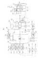
図1は本発明を採用した電気自動車の充電システムの構成を示している。 FIG. 1 shows a configuration of an electric vehicle charging system employing the present invention.
本実施例の電気自動車の充電システムは、マンションなどの集合住宅(以下、単に「集合住宅」と称する)に設置されるもので、図1に示すように、充電出力手段として電気自動車を複数台それぞれ充電する充電器303、303…を含む。これら充電器303、303…は、集合住宅の駐車スペース(あるいは充電専用のスペース)などに配置される。 The electric vehicle charging system according to the present embodiment is installed in an apartment house such as a condominium (hereinafter simply referred to as “apartment house”). As shown in FIG. Each of the
本実施例の充電システムは、バッテリーの電力を出力できる電気自動車5001、5002、5003…に対応し、これら電気自動車からの出力を他の負荷のために(後述するように他の電気自動車の充電のため、ないしはマンション共用部負荷6001(照明、エレベータ、水道のポンプなど)、さらには図1の制御回路(制御部200、充電制御部301、給電制御部4001など)などへの給電のため)供給できるようにしてある。 The charging system of the present embodiment corresponds to
このため、充電器303、303…には充電出力のためのアウトレット3031、3031…とともに、インレット3032、3032…をそれぞれ設けてある。電気自動車とこれらアウトレット3031、3031…、およびインレット3032、3032…の間は所定仕様のコネクタや充電ガンを有するケーブル(不図示)で接続される。ただし、場合によっては電源出力および入力を行なうこれらのケーブルは直出しのケーブルによって構成してもよい。 For this reason, the
充電器303、303…は、電気自動車に対して商用交流電源302の出力(単相100Vや、単相ないし3相200V)をアウトレット3031、3031…を介して不図示の電気自動車に対して出力し電気自動車を充電する。なお、電気自動車の仕様によって、あるいは電気自動車のバッテリを直接充電するような用途のために、充電器303、303…は交流出力ではなくスイッチングレギュレータなどを用いて生成した直流を充電電力として電気自動車に供給できるように構成されていてもよい。 The
一方、電気自動車5001、5002、5003…のうち、給電出力が可能なものは、たとえばDC12V(直流)のアウトレットコネクタを有する。 On the other hand, among
あるいは電気自動車5001、5002、5003…は、100V商用交流負荷のためのアウトレットコネクタを有する仕様のものも考えられるが、本実施例の充電システムでは、説明を容易にするため電気自動車5001、5002、5003…はDC12Vの給電出力を他の電気自動車の充電のため、ないしはマンション共用部負荷6001への給電のため用いるものとする。なお、電気自動車の給電出力のための接続ケーブルに異なる仕様のものを用意したり、充電器303、303…と後述の給電制御部4001との間の給電ライン上にスイッチングレギュレータなどの電圧変換手段を設けることにより、多様な電気自動車の給電出力に対応する充電システムを構成することもできる。 Alternatively, the
充電器303、303…が配置される駐車スペースは各居住者(ユーザ)ごとに割り当てられ、各居住者が保有する電気自動車(電気自転車などを含む)が専有的に使用するスペース、あるいは、他の駐車位置から居住者が車両を移動してきて充電のみ行うような共用の充電スペースであってよい。充電対象の電気自動車は、各居住者が保有するものであってもよいし、また、その集合住宅の居住者で共有(カーシェアリング)されるものであってもよい。充電対象の電気自動車が共有(カーシェアリング)される場合は、電気自動車は所定の予約手続を経て予約管理される。 A parking space where the
本実施例では、電気自動車5001、5002、5003…からの給電出力を他の電気自動車の充電のため、ないしはマンション共用部負荷6001への給電のため用いるが、そのような給電サービスは、たとえば商用交流電源302の停電が生じた場合などに必要となる。本実施例では、このような状況に対応するためにバックアップ無停電電源501および不揮発メモリ209を設けてある。 In this embodiment, the power supply output from the
商用交流電源302は、制御部200(後述)の主電源部(不図示)にも電源供給を行なうが、商用交流電源302〜図1の各制御回路の電源ライン上には、停電時のデータ退避などの停電時の充電中断処理を確実に行なうためにバックアップ無停電電源501を配置してある。図1では、電源ラインを詳細に図示していないが、制御部200への電源ラインは、充電制御部301、給電制御部4001など、図1の他の制御回路ブロックにも接続されている。 The commercial
バックアップ無停電電源501は、充電式バッテリーおよびスイッチングレギュレータ、あるいは大容量のコンデンサ、あるいは発電機などの商用交流電源302に依存しない電源を用いて構成され、制御部200への電源ラインの給電が遮断された場合、直ちに制御部200への電源供給を開始する。当然ながら、バックアップ無停電電源501は、停電時のデータ退避などの停電時の充電中断処理を充分実行できるだけの時間、制御部200(ないしはさらに必要な周辺回路)に給電を行なえる能力を有する。また、バックアップ無停電電源501は、停電により制御部200への電源ラインの給電が遮断された場合、および復旧した場合、割込み信号(INT)を発生し、制御部200のCPU201に対して割込みをかけ、CPU201はこれに応じて後述の停電時および停電復旧時の割込制御を実行する。なお、停電、および停電復旧をCPU201に対して報知する割込み(あるいは検出)信号は、特にバックアップ無停電電源501で発生する必要はなく、他の検出回路が発生するようになっていてもよい。 The backup
アウトレット3031、3031…、およびインレット3032、3032…を有する充電器303、303…は、集合住宅の規模などに応じて複数、N台分用意する(図1では5台分の充電器303のみを図示している)。本実施例では、諸条件、たとえば当該集合住宅で電気自動車の充電に利用できるトータルの電流容量などを考慮し、特定の充電器303、303…のアウトレット3031、3031…を介してこのうちの数台(n台、たとえば3台)を用いて電気自動車を同時充電するものとする。同時充電できるn台を超える分の電気自動車は、他の充電器に接続して、充電待ちの待機状態とすることができる。 A plurality of
充電器303、303…のうち、どの充電器を同時充電するかは充電制御部301により制御される。充電制御部301は後述の制御部200と同様にCPU、ROM、RAMなどの部材から構成され、制御部200と通信することにより、充電器303、303…の充電出力をオン/オフする。 The
また、充電制御部301は充電器303、303…のそれぞれの状態、たとえば、動作中か否か、現在の充電電流の値、などを制御部200との通信を介してCPU201に報知することができ、CPU201はこれにより現在の各充電器303、303…の状態を把握し、後述のような充電制御を行なうことができる。 Further, the charging
また、充電器303、303…の各インレット3032、3032…からの各々の電源入力ラインから入力された電力の給電制御は給電制御部4001により制御される。給電制御部4001は、充電制御部301と同等の構成を有し、後述の制御部200により制御される。 Further, power supply control of power input from each power input line from each of the
給電制御部4001は、各インレット3032、3032…に入力されたDC12Vの直流を単相100Vの交流に変換するDC−ACコンバータを内蔵するものとする。給電可能な電気自動車が接続された充電器303のインレット3032からの電源入力ラインから入力した電力をアウトレット3031に充電すべき電気自動車が接続された充電器303(のみ)へ、あるいは、マンション共用部負荷6001へ供給する給電制御を行なう。 The power
一方、図1の右方には物品収受装置100が示されている。物品収受装置100は、いわゆる宅配物の授受に用いる宅配ボックス(宅配ロッカー)や、郵便受けなどとして構成される。 On the other hand, an
図1の物品収受装置100は、たとえば集合住宅の(宅配業者や郵便配達員がアクセスできる)公共側に面する側を図示してある。 The
物品収受装置100は、複数の物品収受ボックス101、101…から構成され、物品収受ボックス101が郵便受けとして構成される場合には破線で示すように投函口102、102…が設けられ、物品収受ボックス101…の投函口102とは反対側(不図示)の面には郵便物を取り出すための電気錠(あるいは番号キー)により開閉される扉(不図示)が設けられる。 The
物品収受ボックス101、101…が宅配ボックスとして構成される場合には、図示の公共側の面は宅配業者が宅配物を収容するための扉(この扉は居住者が宅配物を取り出すための扉を兼ねていてもよい)として構成され、その反対側には居住者が宅配物を取り出すための扉(不図示)が設けられ、これらの扉の開閉は電気錠により制御される。 When the
物品収受ボックス101、101…の郵便物を取り出すための扉、あるいは宅配物を収容し、また取り出すための表裏の2つの扉の開閉は、コンソール103での居住者(あるいは宅配業者)操作に応じて制御部200により制御される。 Opening and closing of the doors for picking up the mails in the
コンソール103は、ここでは便宜上、公共側に配置されたものを図示しているが、ほぼ同じ構造のものをプライベート側(図示した側と反対側)に設けることができる。 For convenience, the
コンソール103には、LCDパネルなどから構成されたディスプレイ104、ファンクションキーやテンキーから成るキーボード105、および認証手段としてのIDカード111の情報を読み取るカードリーダー102が設けられる。 The
IDカード111は、集合住宅の居住者がそれぞれ保有するもので、たとえばその居室番号などがID情報として記録されたICカードなどにより構成される。また、当該集合住宅以外のIDカード111を用いたりできないように、IDカード111には、当該集合住宅で用いることができる正規のカードであることを示す特定の鍵情報を格納したり、あるいは居室番号などのID情報を当該集合住宅のみで通用する鍵情報を用いて暗号化して記録したりすることができる。 The
また、IDカード111は、宅配物(あるいは郵便物や郵便小包)を収容するため物品収受ボックス101、101…の公共側の扉を開錠するために用いる特別なカードとして特定の宅配業者(あるいは郵便配達人)に配布することもできる。さらに、IDカード111は、集合住宅のエントランスの扉(不図示。いわゆるオートロック制御される玄関扉)や、居住者個々の居室を開閉する鍵として機能するカードキーを兼ねていてもよい。 The
さらに、本実施例では、IDカード111は、居住者が電気自動車(自己の保有する車両、あるいはカーシェアリングにより貸与される車両)を充電するための充電サービスを受けるために必要な認証を行なう認証手段としても用いる。 Further, in this embodiment, the
すなわち、本実施例では、IDカード111は、充電器303、303…により提供する充電サービスに対するユーザ認証手段としても用いられる。 In other words, in this embodiment, the
このために、コンソール103のみならず、IDカード111を読み取るカードリーダー(102と同等のもの)を含む充電制御用のコンソール(不図示)を充電器303、303…の近傍に(個々の充電器のそれぞれ近傍または充電スペースの所定場所に1ないし数個)に配置することもできる。 For this purpose, not only the
また、充電器303、303…の筐体にそれぞれこのようなカードリーダーを有するコンソールを配置してもよい。居住者(あるいは管理者)の充電サービスに関する操作は、図示のコンソール103ないし、充電器303、303…に、あるいはその近傍に設けた不図示のコンソールのいずれによっても行なうことができるが、以下では便宜上、また、説明を容易にするため図示のコンソール103を用いて居住者(あるいは管理者)の充電サービスに関する操作が行なわれるものとする。 Moreover, you may arrange | position the console which has such a card reader in the housing | casing of charger 303,303 ..., respectively. The operation related to the charging service of the resident (or manager) can be performed by the illustrated
以上のように特定の居住者と1:1に対応づけられたIDカード111を用いることにより、後述のように特定の居住者の電気自動車の充電サービスの利用行動に係わる情報、ないしは、その居住者が充電サービスを受ける電気自動車に係わる情報をデータベース情報として蓄積し、該データベース情報を用いて効率よく迅速に複数の電気自動車を充電することができる。 As described above, by using the
物品収受装置100の制御部200は、コンソール103でのIDカード111の提示、操作に応じて、物品収受装置100の物品収受ボックス101、101…を施錠/開錠する電気錠の開閉制御を行なう。 The
また、上述のように、IDカード111には、物品収受装置100の施錠/開錠操作のほか、居住者(保有する、あるいは使用の権利のある電気自動車)に対する充電サービスを関連づけ、IDカード111によって充電サービスの認証を行なうようにすることから、物品収受装置100の制御部200は、物品収受装置100の制御および充電制御部301が制御する充電サービスを統合的に制御する。 Further, as described above, the
その際、特定の居住者の電気自動車の充電サービスの利用行動に係わる情報、ないしは、その居住者が充電サービスを受ける電気自動車に係わる情報をデータベース情報として蓄積し、該データベース情報を用いて複数の電気自動車の充電制御を行なうことができる。 At that time, information relating to the usage behavior of the charging service of the specific resident's electric vehicle, or information relating to the electric vehicle for which the resident receives the charging service is accumulated as database information, and a plurality of pieces of information are stored using the database information. Electric vehicle charging control can be performed.
制御部200は、主制御部としてのCPU201、後述のプログラムを格納したROM202、ワークエリアとして用いられるRAM203、充電制御部301と通信するための所定通信方式によるインターフェース205(たとえば IEEE 802.3 ネットワークインターフェース、シリアルインターフェースなど)、さらに現在時刻を計時する、たとえばバッテリバックアップされたリアルタイムクロック(RTC)のような計時手段などから構成される。 The
さらに制御部200には、HDDや不揮発メモリカードから成る外部記憶装置207が接続されており、後述のプログラム、および充電・給電処理データベース情報はこの外部記憶装置207に格納される。 Furthermore, an
また、CPU201には、不揮発メモリ209が接続されており、CPU201は、停電時、バックアップ無停電電源501からの割込み信号(INT)に応じて充電制御を続行できるよう不揮発メモリ209に制御データを退避させる。不揮発メモリ209はEEPROMやバッテリーバックアップされたRAMなどの半導体メモリから構成することができるが、上述のHDDなどから成る外部記憶装置207の記憶領域を不揮発メモリ209として用いるようにしてもよい。 Further, the
また、制御部200は、ネットワークインターフェース(たとえば IEEE 802.3 ネットワークインターフェースや所定方式の WAN インターフェースなど)204を有し、ネットワーク206(イントラネットやインターネット)を介して遠隔地のサーバと通信することができる。後述の制御の一部は、制御部200のみならず、ネットワーク206を介して接続されるサーバによって代行することができる。特に、後述のデータベース情報の蓄積や管理は、このようにネットワーク206を介して接続されるサーバによって実施するようにしてもよい。 The
また、制御部200は、ネットワークインターフェース204を経由してネットワーク206上にあるメールサーバを用いて、居住者(ユーザ)に対して、たとえば当該居住者が登録した電気自動車の充電サービスの充電開始、および後述の充電終了検出制御(図5、図6)によって制御される充電終了などを通知するメールを送信できるようにしておく。また、充電サービスの開始や終了の通知は、当該集合住宅のインターホン(不図示)を介して行なうこともできる。集合住宅のインターホンとの接続は、ネットワークインターフェース204ないし他の専用信号線を介して行ない、たとえば居住者の居室のインターホンの表示装置などに特定の表示を行なうことにより電気自動車の充電の開始や終了の通知を実施することができる。 In addition, the
図2および図3は、図1のような本実施例の物品収受装置および充電システムからなる装置の制御に用いられるデータベースの構成の一例を示している。 FIG. 2 and FIG. 3 show an example of the configuration of a database used for controlling an apparatus including the article receiving apparatus and the charging system of this embodiment as shown in FIG.
図2および図3のデータベースは、制御部200の外部記憶装置またはネットワーク206を介して制御部200と接続されるサーバの外部記憶装置(いずれも不図示)の記憶領域(通常特定のデータベース方式におけるデータベースファイル)を用いて構成される。 2 and 3 are stored in an external storage device of the
この種のデータベースは、通常、いわゆるリレーショナル形式で、複数の記憶領域を関連づける形で種々のデータレコードを格納する。図2は、本実施例のシステムにおける主データベースの概要を示しており、符号1301〜1304で示すフィールド、すなわち、居室ID、物品収受ボックスID、物品収受データベースへのポインタ、充電・給電処理データベースへのポインタ、から構成される。 This type of database usually stores various data records in a so-called relational format in a manner that associates a plurality of storage areas. FIG. 2 shows an outline of a main database in the system of the present embodiment. Fields indicated by
このうち、居室ID1301は、IDカード111によって識別される居住者の居室ID(たとえば居室の部屋番号)を格納する。 Among these, the
物品収受ボックスID1302には、物品収受ボックス101が郵便受け、宅配ボックスのいずれの場合であっても、居室ID1301のデータの示す居住者に対応づけられた物品収受ボックス101が存在する場合に、そのボックスのID(番号)が格納される。 Even if the
居室ID1301、および物品収受ボックスID1302には、特定のIDカード111に対して特定の居住者ないし物品収受ボックス101のボックスIDを発行する登録時に上記の情報が格納される。この登録処理は上記のコンソール103、あるいは不図示の別の登録システムを用いて実行する(本発明の本質とはほとんど関係しないのでここではその詳細については説明を省略する)。 The
物品収受データベースへのポインタ1303は、当該居住者の物品収受ボックス101を用いた物品収受に関する物品収受データベースの格納領域へのポインタ(ファイル名や、メモリアドレス)である。この物品収受データベースには、当該居住者に対して物品収受ボックス101により行なわれた物品(宅配物、郵便物など)の収受に関する情報、たとえば着荷日時や、物品収受サービスに関して課金が行なわれる場合にはその課金情報などが蓄積される。ここでは、この種の物品収受を管理する物品収受データベースについては公知であるから詳細な説明は省略するが、物品収受データベースへのポインタ1303の値として例示したP11〜P13の意味は後述の充電・給電処理データベースへのポインタ1304の値P21〜P23と同様に他の特定のデータベース領域へのポインタ(ファイル名や、メモリアドレス)である。 A
充電・給電処理データベースへのポインタ1304は、当該居住者の電気自動車の充電サービスの利用行動に係わる情報、ないしは、その居住者が充電サービスを受ける電気自動車に係わる情報を図3に示すように蓄積する充電・給電処理データベースの格納領域へのポインタ(ファイル名や、メモリアドレス)である。充電・給電処理データベースへのポインタ1304の値P21、P22は、それぞれ図3に示す他のデータベース格納領域へのポインタである。 As shown in FIG. 3, the
上記のような主データベースが用意されていれば、IDカード111がコンソール103のカードリーダー102に提示されるなどして、CPU201が居住者のID情報であるIDカード111に記録された居室IDを取得すると、その居室IDを用いて図2の居室IDのフィールド1301を参照することによりその居住者に割り当てられた物品収受ボックスID(フィールド1302)を特定することができる。 If the main database as described above is prepared, the
また、ポインタ格納フィールド1303、1304を参照することにより図3に示すような充電・給電処理データベースの格納領域を特定し、その領域に格納されたデータを取り出して利用し、また、特定の居室IDの居住者に対して新たな充電サービスの実施があった場合には、その内容に応じて充電・給電処理データベースの対応するデータを更新することができる。 Further, by referring to the
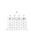
図3の充電・給電処理データベースは、以下に示すように特定の居住者の充電サービスおよび給電サービスに係わる情報、すなわち、特定の居住者が亨受した充電サービスに関する情報を格納するもので、図の行方向の1レコードに当該居住者が亨受した1回の充電サービスに関する情報がそのレコードを構成する各フィールドに格納される。 As shown below, the charging / power supply processing database of FIG. 3 stores information related to the charging service and power supply service of a specific resident, that is, information related to the charging service received by the specific resident. Information on one charge service received by the resident in one record in the row direction is stored in each field constituting the record.
なお、図3の符号P21、P23は、図2の居室ID101および102のレコードに格納されたポインタP21およびP23を示しており、これらの居室ID101および103により識別される居住者の充電・給電処理データベースの先頭レコードを示している。図3の符号P21、P23に関しては図2に図示されていないが、同様に図2のデータベース情報を介して特定の居室IDと関連づけられている。なお、ここでは、説明を容易にするために、1つの表形式で居室IDにより識別される居住者の充電・給電処理データベースがあたかも1ファイルに格納されるが如く図示しているが、実際にはこれらの異なる居住者の充電・給電処理データベースはそれぞれ別のデータベースファイルに格納されていてもよい。 3 indicate the pointers P21 and P23 stored in the records of the
図3の充電・給電処理データベースのレコードは、符号401〜409で示すような各フィールドにより構成されている。 The record of the charging / power supply processing database in FIG. 3 is configured by fields as indicated by
フィールド401は、この居住者のある充電サービスないし居住者が電力を提供した給電サービスの開始日時、フィールド402は、当該充電・給電サービスの充電終了日時を格納する。 The
フィールド405には、種々の充電条件を格納する。この充電条件には、たとえば当該居住者の電気自動車の車種情報や、充電電流、充電電流の変化パターンなどを格納する。 A
このうち、電気自動車の車種情報は、充電サービスに係る登録時に居住者が申告した車種情報であってもよいが、好ましくはたとえば充電サービスごとに充電電流の推移パターンなどから車種情報を推定して格納することが考えられる。このように充電電流の推移パターンなどから車種情報を推定するには、あらかじめ充電電流の推移パターンと車種情報を関連づけた他のデータベース情報(不図示)を用意しておく。そして、当該充電サービスにおける実際の充電電流の推移パターンから、車種情報との関連づけを格納したデータベース情報を参照することにより車種情報を特定することができる。 Among these, the vehicle type information of the electric vehicle may be the vehicle type information declared by the resident at the time of registration related to the charging service, but preferably the vehicle type information is estimated from, for example, the charging current transition pattern for each charging service. It can be stored. In order to estimate the vehicle type information from the charging current transition pattern and the like in this way, other database information (not shown) in which the charging current transition pattern and the vehicle type information are associated in advance is prepared. The vehicle type information can be specified by referring to the database information storing the association with the vehicle type information from the actual charging current transition pattern in the charging service.
また、フィールド405には、さらに当該ユーザの車両の充放電特性も格納することができる。車両の充放電特性に関する情報があれば、たとえばある車両から給電を行なわせる場合に、ある電力量であと何時間給電を行なえるか、などを特定し、警告情報を発生したり、あるいは他の給電を行なえる車両が存在しないか、などを検索する処理も可能となる。なお、このような車両のバッテリーの充放電特性は、電気自動車側との間に特別な通信ラインがあれば、電気自動車側から通知させたり、あるいは充電期間の間の短時間に充電ラインをオープンとし、その前後で電気自動車側からバッテリー残量をそれぞれ報知させるような手法により取得することができる。また、フィールド405の車種情報の一部に、当該車種のデータ(仕様)としてメーカーが公開している充放電特性を格納しておき、この充放電特性を用いるようにしてもよい。このように充放電特性のデータは、種々の方法で実測、あるいは蒐集することができ、どのようなデータベースフィールドに格納してもよく、独立したデータベースを設けてそこに格納してもよい。 The
また、電気自動車の充電においては、たとえば電気自動車側のレギュレータを介した自動制御などにより、電気自動車に対して供給される充電電流が刻々変化する。このような各電気自動車に固有の充電電流の変動(推移)パターンをあらかじめ分類して他のデータベース(不図示)として用意しておけば、当該充電サービスにおける充電電流の変動(推移)パターンと比較することなどにより、A、B、Cのようなニーモニックによって識別されるパターン情報を特定し、フィールド408に格納することができる。これらのニーモニックによって識別される充電電流の変動パターン(波形変化)は、たとえば、充電期間の最初から最後までほぼ充電電流が一定であるとか、充電期間の最後に漸時充電電流を減衰させる制御が入るとか、あるいは充電期間の最後にパルス充電のような特別なパターンで充電電流を減衰させる区間が入る、といったいくつかのパターンに相当させておくとよい。 In charging an electric vehicle, for example, the charging current supplied to the electric vehicle changes every moment by automatic control via a regulator on the electric vehicle side. If such a variation (transition) pattern of charging current unique to each electric vehicle is classified in advance and prepared as another database (not shown), it is compared with the variation (transition) pattern of charging current in the charging service. By doing so, pattern information identified by mnemonics such as A, B, and C can be specified and stored in the
さらに、フィールド405の充電条件情報としては、少なくとも図3の行方向の1レコードに関する充電サービスに関する当該電気自動車に充電した電力を、上述の他の負荷(他の電力自動車、マンション共用部負荷、図1の制御回路(制御部200、充電制御部301、給電制御部4001など)に給電するのを許諾するか否か、のフラグが格納される。この給電の許諾は、1つの充電サービスごとに居住者(ユーザ)が行なうものであってもよいし、特定の車両ごとに居住者(ユーザ)が行なうものであってもよい。また、給電の許諾は、居住者(ユーザ)単位で行なわれる統轄的許諾(つまり当該の居住者は「他の負荷への給電を(いつでも)許諾しますよ」という意味の許諾)であってもよい。これらの許諾は、上記のような許諾の性質に応じて充電開始の際、あるいは充電システムへのユーザ登録の際に、コンソール103などを介して行なうものとする(上記の統轄的許諾の場合にはユーザ登録の際などに入力された許諾情報がフィールド405にコピーされる)。 Further, as the charging condition information in the
フィールド408には給電サービスに係る情報を格納する。図3の行方向の1レコードが充電サービスである場合には、フィールド408には特定のビットパターンなどにより識別される無効情報(図3中の×印に相当:他のフィールドに関しても同様)を格納する。当該1レコードが充電サービスである場合(たとえば図3のP26)には、フィールド408には特定のビットパターンなどにより識別される給電フラグを少なくとも格納するとともに、給電電力量(W/h)やその変動に関する情報を記録する。 The
フィールド409には当該充電サービスに関する課金情報を格納する。課金情報は、単価(固定値、または充電電流に応じて定まる従量値)と充電所要時間の積、などにより求められる。なお、図示した課金方式はあくまでも一例であり、他の課金方式を用いる場合には異なる算出方法を用いてよい。また、課金情報は、他の格納位置に別のデータベースファイルなどとして記憶させるようにしてもよい。 The
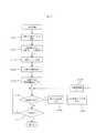
次に、上記構成における充電制御の一例につき、充電制御および給電処理をそれぞれ示した図4、図5のフローチャートを参照して説明する。 Next, an example of the charge control in the above configuration will be described with reference to the flowcharts of FIGS. 4 and 5 showing the charge control and the power supply process, respectively.
図4のフローチャートは、制御部200のCPU201、あるいはさらにCPU201と充電制御部301の連携により実行される本充電システムの充電制御の全体の流れを示している。図4の充電制御プログラムは、制御部200のROM202(あるいは不図示の外部記憶装置)、あるいはさらに処理の一部が充電制御部301により実行される場合、その部分は充電制御部301のROM(あるいは不図示の外部記憶装置)などに格納される。 The flowchart of FIG. 4 shows the overall flow of the charging control of the present charging system that is executed by the
図4の処理が前提とする充電処理は次のようなものである。 The charging process premised on the process of FIG. 4 is as follows.
本実施例では、当該集合住宅で電気自動車の充電に利用できるトータルの電流容量などを考慮し、このうちのn台(たとえば3台)を用いて電気自動車を同時充電する。同時充電できるn台を超える分の電気自動車は、他の充電器に接続して充電待ちの待機状態とする。1台の電気自動車に対する充電は、特定のユーザ(居住者)が、コンソール103にIDカード111を提示して申し込み、登録した1個の充電サービスにより行なわれ、したがって、制御部200が行なう充電制御では同時にn個の充電サービスがユーザ(居住者)に提供される。 In the present embodiment, considering the total current capacity that can be used for charging the electric vehicle in the housing complex, n electric vehicles (for example, three vehicles) out of these are simultaneously charged. The number of electric vehicles over n that can be charged simultaneously is connected to another charger and placed in a standby state waiting for charging. Charging for one electric vehicle is performed by one charging service that is registered and registered by a specific user (resident) by presenting the
電気自動車の充電を申し込むには、居住者がコンソール103のカードリーダー102に自己のIDカード111を提示し、コンソール103で所定の操作を行ない、充電サービスの登録を行なうものとする。このユーザーインターフェースは制御部200のCPU201により制御され、その細部の構成は任意であるが、重要な点は居住者がコンソール103のカードリーダー102に対して認証手段としての自己のIDカード111を提示することにより、充電サービスに関する認証が行なわれる点である。 In order to apply for charging of the electric vehicle, the resident presents his / her
これにより、CPU201は居住者の居室IDを認識し、図2および図3のデータベースを参照し、当該居住者の過去の電気自動車の充電サービスの利用行動に係わる情報、ないしは、その居住者が充電サービスを受ける電気自動車に係わる情報をデータベース情報などにアクセスすることができるとともに、これらの情報をこれから実施する充電サービスの実際の態様に応じて更新することができる。 As a result, the
また、もちろん、IDカード111は、充電サービスのユーザとしての居住者に当該充電サービスを提供するか否かを決定するためのユーザ認証手段としても機能し、適正なIDカード111がカードリーダー102(あるいは充電器303やその近傍に配置されたカードリーダー)に提示されない場合は充電サービスの提供を禁止することができ、これにより適正なIDカードを提示した者以外に対する不正な充電サービスの提供を防止することができる。 Of course, the
なお、居住者が登録した充電サービスにおいていずれの充電器303を用いるかは、居住者が手動でコンソール103のキーボードなどを用いて空きとなっている充電器303、303…の一台を指定するか、制御部200のCPU201が空きとなっている充電器303、303…を指定してもよい。居住者は充電開始時刻(下記)までに指定した、あるいは指定された充電器303に充電する電気自動車を接続して待機するものとする。 Note that which
複数台の電気自動車に対する充電サービスの提供に際しては、電気自動車が充電器303に接続され、コンソール103を用いてユーザの充電サービスに関する登録が完成した時点で直ちに充電を開始する方法が考えられるが、本実施例では同時充電するn台の電気自動車のグループの内訳(申し込みのあったいずれの電気自動車のうちどのn台を同時充電するか)を効率よく決定し、また、その後、電気自動車のいずれかが充電終了となった時点で充電待ちになっているどの電気自動車の充電を開始するか、といった充電の順序を効率よく決定するために、充電サービスの登録(申し込み)後に直ちに充電を開始するのではなく、充電サービスの登録は随時受け付けるが、実際の充電開始は一日のうち、たとえば、9:00、12:00、15:00、18:00などの決まった定時に開始するものとする。このような制御により、充電サービスの登録と複数台から成るグループの電気自動車に対する充電サービス開始との間にタイムラグを置くことによって、より効率的で、しかも集合住宅の電流容量をオーバーすることなく、確実な充電制御を行なうことができる。 In providing a charging service for a plurality of electric vehicles, a method of starting charging immediately when the electric vehicle is connected to the
さて、図4の充電制御は、制御部200に設けられた不図示のリアルタイムクロックの計時などにしたがって、上記の充電開始の定時タイミングのわずか前に開始されるものとする。 Now, it is assumed that the charging control of FIG. 4 is started slightly before the above-described scheduled timing of the start of charging in accordance with the timing of a real time clock (not shown) provided in the
制御の対象となる充電サービスは、図4の処理開始前までに居住者がコンソール103を用いて登録を完了した有効な充電サービスである。 The charging service to be controlled is an effective charging service in which the resident has completed registration using the
図4のステップS101では、申し込み順で1グループで同時実施するn個の充電サービスを仮選択する。 In step S101 of FIG. 4, n charging services to be simultaneously performed in one group in the order of application are temporarily selected.
ここでは、既に登録を完了した有効な充電サービスのうち、登録を完了した時刻の早い順で完了した充電サービスを選択し、同時充電するn個の充電サービスと、それに対応するn台の1グループの充電器303、303…を選択する。 Here, among valid charging services that have already been registered, a charging service that has been completed in the order of the time at which registration was completed is selected, and n charging services that are charged simultaneously, and one group of n corresponding to the charging services.
充電器303と登録されている充電サービスの関係は上記の登録処理によってCPU201が認識している。さらにCPU201は、当該充電サービスを登録した特定の居住者の居室IDを用いて図2および図3の過去の充電・給電処理データベースを参照することができる。 The relationship between the
これによって、当該居住者の充電・給電処理データベースに記録された情報から当該居住者が充電する電気自動車の車種情報、所要充電電流、や充電電流パターンなどの情報(図3の405)にアクセスすることができる。 Thereby, information (405 in FIG. 3) such as vehicle type information, required charging current, and charging current pattern of the electric vehicle charged by the resident is accessed from information recorded in the charging / power supply processing database of the resident. be able to.
続いて、ステップS102において、同時に実行(提供)するn個の充電サービスの組合せを決定する。本実施例では、このとき電気自動車の車種情報、所要充電電流、充電電流パターン(図3の405)などの情報を用いて、現在選択中のn個の充電サービスの組合せが最適になるまで同時に実行(提供)するn個の充電サービスの組合せを選び直す。すなわち、同時実行する充電サービスの組合せを最適化する。ここでは、現在選択中のn個の充電サービスの組合せが最適か否かを判定し、充電・給電処理データベースにしたがって仮選択状態の1または数台分の充電サービスを仮選択状態となっていない他の充電サービスと入れ換える。 Subsequently, in step S102, a combination of n charging services to be simultaneously executed (provided) is determined. In this embodiment, at this time, information such as the vehicle type information of the electric vehicle, the required charging current, and the charging current pattern (405 in FIG. 3) is used until the combination of the n currently selected charging services is optimized. Select a combination of n charging services to be executed (provided). That is, the combination of charging services to be executed simultaneously is optimized. Here, it is determined whether or not the combination of the n charging services currently selected is optimal, and one or several charging services in the temporarily selected state are not in the temporarily selected state according to the charging / power supply processing database. Replace with other charging services.
このときの充電サービスの最適化(入れ換え)の条件の最も重要な1つは、電気自動車n台分の充電に必要なトータルの電流容量が、複数の充電サービスの同時提供に際して要求される上限値、特に本実施例においては集合住宅の商用交流電源302によって供給可能な最大電流容量を超過しないようにする、という点である。この条件は、たとえば商用交流電源302の電源ラインに挿入されているブレーカーが断となって全ての充電処理が実行できなくなるのを防止するために必須である。この最重要条件を判定するには、具体的には、仮に定めた充電サービスの組合せにそれぞれ該当する居住者につき、図3のフィールド405の充電電流(たとえば過去の充電処理における充電電流値)を参照し、その総和が上記の上限値を超過しないか判定する処理を行なえばよい。 One of the most important conditions for the optimization (replacement) of the charging service at this time is that the total current capacity required for charging n electric vehicles is an upper limit value required for simultaneous provision of a plurality of charging services. In particular, in this embodiment, the maximum current capacity that can be supplied by the commercial
その他の最適化条件としては、種々の条件が考えられ、当業者において任意に採用して構わないが、たとえば、次のような最適化条件が考えられる。 As other optimization conditions, various conditions are conceivable and may be arbitrarily adopted by those skilled in the art. For example, the following optimization conditions are conceivable.
その1つは、過去の充電・給電処理データベースから、ある充電サービスについて、そのサービスに対応する居住者がどのような充電処理をとってきたかに応じて当該の充電サービスと他の充電サービスとを同時実行するか否かを決定するものである。 One is that the charging service and other charging services are determined according to what kind of charging process the resident corresponding to the service has taken from a past charging / power supply processing database. It is determined whether or not to execute simultaneously.
たとえば、過去の充電・給電処理データベースから、その居住者が実行した充電が長時間の充電が多いのか、短時間の充電が多いのかを特定することができる。 For example, it is possible to specify from the past charge / power supply processing database whether the charge performed by the resident is a long-time charge or a short-time charge.
そこで、最適化条件のひとつとして考えられるのは、充電サービスを登録した居住者全員の電気自動車を一斉に同時充電できない場合、居住者に充電待ちをさせる待ち時間ができるだけ小さくなるようにする、という戦略である。この場合には、図3の充電・給電処理データベースのフィールド401、402に記録された過去の充電時間長のうち、短い充電時間長が多かった居住者の充電サービスを先に実行するように充電サービスを入れ換える(充電時間長の多い居住者の充電サービスはあと回しにする)。これにより、たとえば「近所に出掛けるため、短時間の充電をしたいだけなのに長時間待たされた」といった居住者の不満を回避することができるようになる、と考えられる。 Therefore, one possible optimization condition is to minimize the waiting time for the residents to wait for charging if all the electric vehicles of all the residents who have registered charging services cannot be charged simultaneously. It is a strategy. In this case, charging is performed so that the charging service of the resident who has a long short charging time length among the past charging time lengths recorded in the
さらに、図3のような充電・給電処理データベースを用意している場合には、現時点で登録されている特定の充電サービスが長時間に渡るものになるか、それとも短時間で済みそうかをより確実に特定することもできる。たとえば、図3のフィールド401、402に記録された充電開始および終了日時を参照すれば、サービスの利用日時が平日か週末かなどを特定できる。そして、たとえばある居住者は(ないしこの居住者の充電する電気自動車使用の態様が)平日には短時間の充電を行ない、週末には遠方にドライブするために長時間の充電を必要とする、というような充電サービス利用行動をとる、などと推定できる。 Furthermore, when a charging / power supply processing database as shown in FIG. 3 is prepared, it is determined whether the specific charging service registered at the present time will be for a long time, or whether it will take a short time. It can also be identified reliably. For example, referring to the charging start and end date / time recorded in the
あるいは、平日、週末の観察のみならず、月のうち上旬、中旬、下旬に分けて特定居住者の充電処理を解析することもできる。たとえば、下旬になると(月末が近付くと)、充電時間長L(長)のレコードが減り、充電時間長S(短)のレコードが増える、というような充電サービス利用パターンが読み取れる場合もある。このようなケースは、たとえば、月末に近づくにつれ、長距離のレジャー利用が減り、短距離のビジネス利用が増加する、といった充電サービス利用パターンに相当すると考えられる。 Alternatively, not only the observation on weekdays and weekends, but also the charging process of a specific resident can be analyzed separately in the early, middle and late months of the month. For example, when the end of the month is approaching (when the end of the month is approaching), there may be a case where the charging service usage pattern such that the charging time length L (long) record decreases and the charging time length S (short) record increases can be read. Such a case is considered to correspond to a charging service usage pattern in which long-distance leisure use decreases and short-distance business use increases as the month approaches, for example.
この場合には、制御部200のリアルタイムクロックの計時によって判明する現在日時(曜日や旬日)によって、特定の居住者の登録した充電時間がどれくらいになりそうかをより確実に推定できる。したがって、この場合には、ステップS102において、上記の充電・給電処理データベースの短い充電時間長の多い居住者の充電サービスを先に(優先して)実行するという戦略に、現在の日時(たとえば曜日や旬日)と、特定居住者の充電サービスの利用日時(たとえば曜日や旬日)との関係から推定される特定の充電サービスの関係に関する解析結果を組合せて、より確実に居住者の登録した充電時間がどれくらいになりそうかを予め判定できる。たとえば、短い充電時間が多い居住者の充電サービスであっても、週末にかかる現在日時においては、データベースレコードがその登録された充電サービスが長時間充電になりそうな充電処理を示している居住者の充電サービスは後回しにする、といった制御を行なうことができる。 In this case, it is possible to more reliably estimate how long the charging time registered by a specific resident is likely to be based on the current date and time (day of the week or seasonal date) determined by the timekeeping of the real time clock of the
なお、ステップS102の段階で図4の処理開始以前から引き続き実施中の充電サービスがあれば、引き続きそのまま続行させるためにステップS102およびS103における最適化処理から除外することができる。あるいは、続行中の充電サービスがあっても、ステップS102およびS103における最適化処理に含めても構わない。いずれの仕様を採用するかは当該集合住宅の充電サービス規約に応じて決定してよい。 It should be noted that if there is a charging service that is still being implemented before the start of the process of FIG. 4 at the stage of step S102, it can be excluded from the optimization process in steps S102 and S103 in order to continue as it is. Alternatively, even if there is an ongoing charging service, it may be included in the optimization process in steps S102 and S103. Which specification is adopted may be determined according to the charging service agreement of the apartment house.
以上のようにして、ステップS102において1グループで同時実施するn個の充電サービスの最適化が終了すると、ステップS104で同時実施するn個の充電サービスの1グループを確定する。そして、他のすぐに実施できない(後程実施する)前記n個を超える数の後続の充電サービスについては、それらを順次実行する仮の順序を定めておく。すなわち、他のすぐに実施できない充電サービスについては、たとえば充電サービス登録の先着順序に応じた順でRAM203上などに確保した待ち行列に登録しておく。 As described above, when the optimization of n charging services simultaneously performed in one group in step S102 is completed, one group of n charging services simultaneously performed in step S104 is determined. Then, for the other number of subsequent charging services that cannot be implemented immediately (to be implemented later), the provisional order in which they are sequentially executed is determined. That is, other charging services that cannot be immediately implemented are registered in a queue secured on the
本実施例においては、この待ち行列上の充電サービス登録順は、仮のものであって、後述のステップS107〜S110において充電終了を検出し、先に順序を定めて待ち行列に登録してある充電サービスを新たに開始する必要が生じた場合に、その時点での充電サービスの実施状況、ないしは過去の各ユーザの充電サービス亨受の態様、すなわち図2、図3の充電・給電処理データベースの登録内容に応じて充電サービスの実行順序を組み換え、同時実行するn個の充電サービスの組合せを決定する。 In this embodiment, the charging service registration order on the queue is tentative, and the end of charging is detected in steps S107 to S110, which will be described later, and the order is first determined and registered in the queue. When it becomes necessary to newly start a charging service, the charging service implementation status at that time, or the charging service reception mode of each user in the past, that is, the charging / power supply processing database of FIGS. The execution order of the charging services is rearranged according to the registered contents, and a combination of n charging services to be executed simultaneously is determined.
また、後述のステップS107〜S110において充電終了を検出する際にも、図2、図3の充電・給電処理データベースの登録内容を参照して得た充電終了条件が用いられる。 Also, when detecting the end of charging in steps S107 to S110, which will be described later, the charging end condition obtained by referring to the registered contents of the charging / power supply processing database of FIGS. 2 and 3 is used.
ステップS105では、n台同時充電制御を開始する所定時刻(たとえば上述の9:00、12:00、15:00、18:00のような定時)が到来しているか否かを制御部200のリアルタイムクロックの計時に基づき判定する。 In step S105, the
ステップS105でn台同時充電制御を開始する所定時刻が到来している場合にはステップS106に進み、CPU201が充電制御部301を介して確定している同時実施すべきn個の充電サービスにそれぞれ対応して登録された特定のn台の充電器303、303…をONとし、それぞれの充電器を介して接続された電気自動車の充電を開始する。なお、各充電器303に関して充電終了フラグ(後述)がRAM203などに配置されるが、これらの充電終了フラグは充電開始に伴ないリセットされる。n個の充電サービスにそれぞれ対応する特定の充電器303、303…との対応は不図示のデータテーブルなどに登録して管理する。 When the predetermined time for starting the simultaneous charging control of n units has arrived in step S105, the process proceeds to step S106, where the
また、ステップS106では、給電可能な電気自動車に対応する充電・給電データベースレコードをフラグする。具体的には、他の負荷(他の電力自動車、マンション共用部負荷、ないし図1の制御回路)に給電するのを許諾しているユーザの電気自動車に対応する図3のフィールド405の給電許諾フラグをオンとする。 In step S106, a charge / power supply database record corresponding to an electric vehicle capable of supplying power is flagged. Specifically, the power supply permission of the
この後、ステップS107以降では、充電処理を終了した充電ジョブが出た場合は、後続の充電待ちになっている充電ジョブの中から、充電開始する充電ジョブを図2、図3の充電・給電処理データベースの内容に応じて決定する(ステップS107〜S110)。 Thereafter, in step S107 and subsequent steps, when a charging job for which charging processing has been completed is issued, the charging job for starting charging is selected from the charging jobs waiting for subsequent charging as shown in FIG. 2 and FIG. It is determined according to the contents of the processing database (steps S107 to S110).
なお、図4の制御に、緊急性ないしは優先度の高い充電サービスを割り込みで優先して実行する処理を組み込んでもよい。たとえば、このような割り込み充電サービスとしては、「特急料金」のような形で割増し料金を居住者にチャージした上で許可する充電サービスが考えられる。あるいは、このような割り込み充電サービスは、コンソール103に「緊急ボタン」のような操作手段を設けておくか、コンソール103で実施するユーザーインターフェースに緊急操作手段を組み込んでおき、急病などの特別な事由に応じて居住者が行なう操作によって発生されるような充電サービスであってもよい。この割り込み充電サービスの制御では、図2、図3の充電・給電処理データベースの内容に応じて、割り込み充電サービスのかわりに中断して待ち行列に回す充電サービスを決定することができる(ステップS107〜S110)。 In addition, you may incorporate into the control of FIG. 4 the process which gives priority and performs a charge service with high urgency or high priority by interruption. For example, such an interrupt charging service may be a charging service that allows a resident to be charged after an extra charge in the form of an “express charge”. Alternatively, such an interrupt charging service may be provided with an operation means such as an “emergency button” on the
また、このような緊急性ないしは優先度の高い充電サービスを設定できるようにした場合には、「特急料金」などによって緊急性ないしは優先度が高く設定された充電サービスに係わる車両にのみ、後述の給電制御により電気自動車からの給電を行なうよう制御することもできる。電気自動車のバッテリーの供給できる電力は限られているから、このような制御を行なうことにより、給電できる範囲を制限することには一定の妥当性があると考えられる。 In addition, when it is possible to set a charging service with such urgency or high priority, only the vehicles related to the charging service with high urgency or priority set by “Express Express” etc. will be described later. It is also possible to control power feeding from the electric vehicle by power feeding control. Since the electric power that can be supplied from the battery of the electric vehicle is limited, it is considered that there is a certain validity to restrict the power supply range by performing such control.
ステップS107では、CPU201は図5に示す充電終了検出制御を行ない、終了した充電サービスがあるか否か、すなわち、充電制御部301と通信し、充電の終了した充電器303があるか否かを判定する。 In step S107, the
ステップS107で終了した充電サービスがある場合には、後述のようにその充電サービスに対応する充電器303に関してRAM203などに配置された充電終了フラグがセットされるため、このフラグの状態に基づいてステップS108において充電制御部301を介して充電を終了した充電器303をオフとし、続いてステップS109においてRAM203上などに確保した待ち行列中に登録され、後続の充電待ちになっている充電ジョブの中から、充電開始する充電ジョブを図2、図3の充電・給電処理データベースの内容に応じて決定する。 If there is a charging service ended in step S107, a charging end flag arranged in the
ここでは、たとえば、1つの充電サービスの終了に応じて、1ないし数個の充電サービスを開始する。というのは、図6に示したように充電期間の後半では漸時充電電流を減少させる制御が多くの電気自動車側で行なわれており、消費電流が低下している場合が考えられるからである。このため、後続の充電待ちになっている充電ジョブの最上位の充電ジョブのうち1ないし数個の充電サービスについて、図3の充電・給電処理データベースに記録されているフィールド405の充電電流、フィールド408の充電電流パターン、あるいはさらにフィールド404の車種情報などを参照し、開始できる充電サービスを1ないし数個選択する。 Here, for example, one or several charging services are started in response to the end of one charging service. This is because, as shown in FIG. 6, in the second half of the charging period, control for gradually reducing the charging current is performed on many electric vehicles, and the current consumption may be reduced. . For this reason, the charging current in the
この選択制御では、もちろん、ステップS102およびS103で説明したのとほぼ同様に、最適化制御のうち、当該集合住宅の商用交流電源302で使用できる最大電流容量をオーバーしないように、との条件がまず適用される。また、ステップS102およびS103で説明したのとほぼ同様に、充電サービスの待ち時間がなるべく少なくなるように、短い充電時間が予想される充電ジョブを優先的に選択するような制御を行なうことができる。 Of course, in this selection control, the condition that the maximum current capacity that can be used by the commercial
なお、ステップS109のように充電制御を開始した後の段階では、図2、図3の充電・給電処理データベースの参照の結果、充電時間が長時間に渡ると推定されることによって充電サービス登録の先着順序から著しく実行順が遅らせられている充電サービスがある場合には、その充電サービスの実行順を早めるように補正を行なってもよい。たとえば、1〜数度、既に充電サービスの実行順を充電サービス登録の先着順序よりも遅らせた充電サービスが存在する場合には待ち行列中の順位を1(ないし数ステップ)上昇させるような補正を行なうようにしてもよい。 In addition, at the stage after starting the charging control as in step S109, the charging service registration is estimated by assuming that the charging time will be long as a result of referring to the charging / power supply processing database of FIGS. If there is a charging service whose execution order is significantly delayed from the first-come-first-served order, correction may be performed so as to advance the execution order of the charging service. For example, if there is a charging service that has already delayed the execution order of the charging service from the first order of the
ステップS109で、開始する充電サービスを決定すると、ステップS110において充電制御部301を介して開始すべき充電サービスに対応する充電器303をONし、ステップS107に復帰する。 When the charging service to be started is determined in step S109, the
一方、ステップS107で終了した充電サービスを検出していない場合には、ステップS115において、全充電サービスが終了したか否かを判定し、全充電サービスが終了した場合には充電制御を終了し、全充電サービスが終了していない場合にはステップS107に復帰して上記の処理を繰り返す。 On the other hand, if the charging service ended in step S107 has not been detected, it is determined in step S115 whether or not all charging services have ended. If all charging services have ended, charging control ends. If all charging services have not ended, the process returns to step S107 and the above processing is repeated.
図5は、制御部200のCPU201、あるいはさらにCPU201と充電制御部301、給電制御部4001の連携により実行される電気自動車のバッテリーを用いて他の負荷(他の電力自動車、マンション共用部負荷、図1の制御回路)に給電する制御の概要を示している。 FIG. 5 illustrates other loads (other electric vehicles, condominium common use loads, etc.) using the battery of the electric vehicle executed by the
図5の給電制御は、たとえば商用交流電源302の停電などの事態に応じて起動する。商用交流電源302の停電は、バックアップ無停電電源501が検出し、割り込み(INT)信号を介して検出できる。なお、停電が生じた場合は不図示の停電割り込み処理により、制御データを不揮発メモリ204に退避させるなどのバックアップ処理が行なわれる。 The power supply control in FIG. 5 is activated according to a situation such as a power failure of the commercial
図5のステップS201では、充電器303、303…に接続されている電気自動車から給電する条件が成立したか否かを判定するが、上記のようにたとえばバックアップ無停電電源501の割り込みにより停電が検出されたか否かを検出する。 In step S201 of FIG. 5, it is determined whether or not a condition for supplying power from the electric vehicle connected to the
図5の給電制御は、他の電力自動車、マンション共用部負荷、図1の制御回路などに給電するのを許諾するフラグ(たとえば図3のフィールド405に格納される)がオンとなっている電気自動車が存在する場合に実行するものとする。たとえば、バックアップ無停電電源501の給電時間が短かい場合には、制御部200、充電制御部301、給電制御部4001などの図1の制御回路が図示の給電を充分な時間実行できないため、この条件が必要となる。 In the power supply control of FIG. 5, the electric power for which a flag (for example, stored in the
以後、しばらくの間、具体的には、後述のステップS203(給電処理の停止)、あるいはS204(電気自動車から図1の制御回路への給電開始)を実行できるだけの時間は、図1の制御回路はバックアップ無停電電源501によって動作する。このようにバックアップ無停電電源501および不揮発メモリ204を設けておくことにより、停電などにより電気自動車から給電サービスを提供してもらわなければならない場合に、給電制御の初期制御をバックアップ無停電電源501からの給電により実行することができる。 Thereafter, for a while, specifically, the time required to execute step S203 (stop of power supply processing) or S204 (start of power supply from the electric vehicle to the control circuit of FIG. 1) described later is the control circuit of FIG. Is operated by the backup
ステップS201で上記の給電条件が成立すると、ステップS202において他の負荷への給電を許諾している電気自動車、具体的にはその車両が接続されている充電器303、303ないしは対応する充電・給電処理データベースレコードを検索し、特定する。 When the above power supply condition is satisfied in step S201, the electric vehicle permitted to supply power to another load in step S202, specifically, the
ステップS203では、給電可能な車両が存在するか否かを判定する。ここでは、他の電力自動車、マンション共用部負荷、図1の制御回路などに給電するのを許諾するフラグが充電・給電処理データベースレコードでオンとなっている車両を検索する。ここでは、あるいはさらにその充電量が充分(所定時間、たとえば1時間以上、他の電力自動車、マンション共用部負荷、図1の制御回路などに給電が行なえる程度)であるか否かを判定するのが望ましい。ステップS203が否定された場合には、給電処理は実行できないのでそれ以上の処理を行なうことなくルーチンを終了する。 In step S203, it is determined whether there is a vehicle that can supply power. Here, a vehicle is searched for which the flag permitting power supply to other electric vehicles, condominium common use load, the control circuit of FIG. 1, etc. is turned on in the charge / power supply processing database record. Here, or further, it is determined whether or not the amount of charge is sufficient (a predetermined time, for example, 1 hour or more, which is enough to supply power to other electric vehicles, condominium common use loads, the control circuit of FIG. 1, etc.). Is desirable. If step S203 is negative, the power supply process cannot be executed, and the routine is terminated without further processing.
ステップS203で給電可能な車両が存在する、と判定された場合には給電制御部4001を介してステップS204で給電ラインをセットアップする。ここでは、給電制御部4001は、充電器303、303…のインレット3032、3032…から充電器303、303…のアウトレット3031に向かう電源ラインを内部の不図示のスイッチ回路などを用いて接続する。インレット3032、3032…を介して電気自動車から供給される直流から交流への変換は給電制御部4001が内蔵するDC−ACコンバータによって行なわれる。また、給電制御部4001は給電制御部4001自身、充電制御部301、制御部200などが動作できるよう、これらの制御回路への給電路を同様に内部のスイッチ回路などを用いて接続する。なお、複数台の給電可能な車両が存在する場合は、並列にそれらの車両が上記各給電路に接続される。 If it is determined in step S203 that there is a vehicle that can supply power, the power supply line is set up in step S204 via the power
ステップS205では、給電レコードの処理(生成・更新)を行なう。たとえば、ここでは、給電サービスを提供する電気自動車のために、充電・給電データベースに給電レコードを新たに生成する。図3では、データベースレコードP26が給電レコードに相当する。このレコードでは、フィールド401、402のスタート、エンド日時として給電開始および終了を記録する。充電に関するフィールド405、407、409には無効情報(×印で表示)を記録する。 In step S205, the power supply record is processed (generated / updated). For example, here, a new power supply record is generated in the charging / power supply database for an electric vehicle that provides a power supply service. In FIG. 3, the database record P26 corresponds to a power supply record. In this record, the start and end of power feeding are recorded as the start and end date / time of the
なお、ここで、課金情報を課金フィールド409に記録しないのは、有料で充電サービスを受けたのに、その充電で得たバッテリーの電力を他の電気自動車に供給するためである。あるいはさらに進んで、給電レコードP26に対応する給電を行なう電気自動車がたとえば充電レコードP23で有料にて充電されていた場合には、当該の充電レコードP23の課金情報を0にする、あるいは給電時間や給電電力量(W/H)などに応じて免除ないし減免するよう充電レコードP23の課金情報(フィールド409)を変更する処理を行なう。 Here, the reason why the charging information is not recorded in the charging
このようにして、給電を許諾している電気自動車のバッテリーを用いて他の電気自動車を充電し、また給電制御部4001自身、充電制御部301、制御部200などの制御回路を動作させることができる。図3のP27は、給電レコードP26に対応する電気自動車の給電により充電される電気自動車の充電レコードに対応する。 In this way, it is possible to charge another electric vehicle using the battery of the electric vehicle that is permitted to supply power, and operate control circuits such as the power
ステップS206では、給電条件があいかわらず成立しているか否かを判定する。たとえば、ここでは少なくとも給電が必要な条件、たとえば停電が依然として続いているか、給電すべき総電力量を給電している電気自動車の総給電電力量が下まわっていないかを判定しなければならない。そして、さらに現在、給電している電気自動車が給電を続行できるだけの充分なバッテリー残量を残しているか、といった条件も判定する。ここで、給電している電気自動車のバッテリー残量は、電気自動車との間に特別な通信路(たとえば無線LAN、充電ケーブルや給電ケーブル中に含まれた通信回線など)を介して直接電気自動車から取得できる場合にはその情報を用いて特定するか、あるいは図3の充電条件フィールド(405)などに格納されている車種や性能に関する情報、特に充放電特性を用いて推定することができる。たとえば、その電気自動車が充電された直前の充電レコード(P23)の充電時間と充放電特性の情報から、現在、給電している電気自動車のバッテリー残量、あるいは現在の消費電流において残りどれだけの時間、給電してもらえるか、などを推定することができる。 In step S206, it is determined whether the power supply condition is satisfied or not. For example, here, it is necessary to determine at least whether the power supply needs to be performed, for example, whether the power outage still continues or whether the total power supply amount of the electric vehicle that supplies the total power amount to be supplied has fallen. Further, it is also determined whether or not the electric vehicle that is currently supplying power has a sufficient remaining battery capacity to continue power supply. Here, the remaining amount of the battery of the electric vehicle being fed is directly connected to the electric vehicle via a special communication path (for example, a wireless LAN, a charging cable or a communication line included in the power feeding cable). Can be obtained from the information, or can be estimated by using information on the vehicle type and performance stored in the charging condition field (405) of FIG. For example, from the information on the charging time and charging / discharging characteristics of the charging record (P23) immediately before the electric vehicle is charged, how much is remaining in the remaining battery power or current consumption of the electric vehicle currently being fed It is possible to estimate the time and whether the power is supplied.
ステップS206で給電続行の条件が成立している場合には、ステップS203に復帰し、上記の処理を繰り返す。なお、ステップS206ではある電気自動車のバッテリー残量は0(%)でなければ給電を続行する、という判定を行なうようにしてもよいが、たとえば20%〜30%程度の残量を切っていなければ給電を続行し、その残量を切ったと判定された場合には当該車両からの給電処理を中止する。 If the condition for continuing power supply is satisfied in step S206, the process returns to step S203, and the above processing is repeated. In step S206, it may be determined that power supply is continued unless the remaining battery level of an electric vehicle is 0 (%). However, for example, the remaining battery level should be about 20% to 30%. If it is determined that the remaining power is cut off, the power supply process from the vehicle is stopped.
一方、ステップS206において、給電が必要な条件、たとえば停電が終っている(バックアップ無停電電源501により検出される)、給電すべき総電力量を給電している電気自動車の総給電電力量が下まわっている、あるいは、全ての電気自動車もバッテリー残量が充分ではない、といった条件が成立した場合は給電続行条件が成立しないため、ステップS207において、給電処理を終了する。ここでは給電レコードにエンド日時(図3のフィールド402)を記録し、給電の態様(たとえば給電電力(ないし電流)の推移など)の情報を給電情報(図3のフィールド408)として記録する。 On the other hand, in step S206, a condition that requires power supply, for example, if the power failure has ended (detected by the backup uninterruptible power supply 501), the total power supply amount of the electric vehicle that supplies the total power amount to be supplied is reduced. If the condition that the remaining battery power is not sufficient for all electric vehicles is satisfied, the power supply continuation condition is not satisfied, and thus the power supply process is terminated in step S207. Here, the end date and time (
以上のように、本実施例では、特定の状況、たとえば停電などによって、商用交流電源からの電源供給が失なわれるような状況において、充電状態にある電気自動車から、その電気自動車と異なる他の負荷、特に充電負荷としての他の電気自動車のみならず、マンション共用部負荷(照明、エレベータ、水道のポンプなど)などへの給電を行なうことができる。また、この給電サービスにおいては、給電制御部4001自身、充電制御部301、制御部200などの制御回路も電気自動車からの給電によって動作させることができる。 As described above, in this embodiment, in a specific situation, such as a situation where power supply from a commercial AC power supply is lost due to a power failure or the like, an electric vehicle in a charged state is different from the electric vehicle. Power can be supplied not only to other electric vehicles as loads, particularly charging loads, but also to condominium common use loads (lighting, elevators, water pumps, etc.). In this power supply service, control circuits such as the power
電気自動車からの給電サービスは、データベース手段に記憶された充電サービスおよび給電サービスに関する情報に応じて実行することができ、これにより、給電が可能かどうかを確認しつつ(図5ステップS203、S206)確実に給電サービスを持続的に実行することができる。また、データベース手段の充電サービスおよび給電サービスに関する情報を更新することにより、たとえば給電サービスを提供した電気自動車の充電に関する課金を免除したり、減免したりする処理が可能となる。 The power supply service from the electric vehicle can be executed according to the information related to the charging service and the power supply service stored in the database means, thereby confirming whether the power supply is possible (steps S203 and S206 in FIG. 5). The power supply service can be reliably executed continuously. Further, by updating the information related to the charging service and the power supply service of the database means, for example, it is possible to perform processing to exempt or reduce the charge related to the charging of the electric vehicle that provided the power supply service.
また、電気自動車からの他の負荷への給電サービスの提供は、個々の充電サービス開始時、あるいは充電サービスのユーザ登録時などにユーザが許諾し、データベース手段に記憶されている許諾情報があって初めてその電気自動車からの給電を行なうよう制御できるため、予め許諾されている電気自動車のみから給電を受け、充電サービスを提供することができ、電気自動車のバッテリー電力を意図せずに消費されてしまうことがない。 In addition, the provision of a power supply service from an electric vehicle to another load is permitted by the user at the start of each charging service or when the user is registered for the charging service, and there is permission information stored in the database means. Since it is possible to control power supply from the electric vehicle for the first time, it is possible to receive power supply only from a pre-licensed electric vehicle and provide a charging service, and battery power of the electric vehicle is consumed unintentionally. There is nothing.
また、たとえば電気自動車の緊急度が低いユーザ(居住者)には、他の負荷への給電サービスを許諾してもらうことによって上記の給電サービスを提供した電気自動車の充電料金の課金の免除や減免のメリットを提供することができる。 In addition, for example, a user (resident) who has a low urgency level of an electric vehicle is permitted to exempt or reduce a charge for charging an electric vehicle that has provided the above-mentioned power supply service by allowing a power supply service to another load. Can provide the benefits.
さらに、マンションなどの集合住宅に宅配ボックスや郵便ポストなどの物品収受装置が配置される場合、その制御部(200)を充電サービスないし給電サービスの制御部と兼用することができ、たとえば、集合住宅の居住者によって提示される認証手段による認証に基づき前記物品収受装置の扉の開閉を制御するとともに、居住者によって提示される認証手段による認証に基づき充電サービスのユーザとしての居住者に当該充電サービスを提供するか否かを決定することができ、さらに前記認証手段による認証を介して、前記充電サービスないし前記給電サービスに関して参照し、更新すべきデータベース手段の情報を特定することができる。また、上記の給電サービスを提供した電気自動車の充電に関する課金を免除や減免に関して参照・更新すべきデータベース手段の情報も、居住者によって提示される認証手段による認証に基づき特定することができる。 Further, when an article collection device such as a delivery box or a post box is arranged in an apartment house such as a condominium, the control unit (200) can also be used as a charging service or power supply service control unit. And controlling the opening and closing of the door of the article receiving device based on the authentication by the authentication means presented by the resident of the person, and the charging service to the resident as the user of the charging service based on the authentication by the authentication means presented by the resident It is possible to determine whether or not to provide the data, and further, through authentication by the authentication means, the information on the database means to be referred to and updated with reference to the charging service or the power supply service can be specified. In addition, information on the database means to be referred to / updated for exemption or reduction of charge related to charging of the electric vehicle that provided the power supply service can also be specified based on authentication by the authentication means presented by the resident.
100 物品収受装置
101 物品収受ボックス
102 投函口
103 コンソール
104 ディスプレイ
105 キーボード
111 IDカード
200 制御部
201 CPU
202 ROM
203 RAM
205 インターフェース
206 ネットワーク
207 外部記憶装置
209 不揮発メモリ
301 充電制御部
302 商用交流電源
303 充電器
501 バックアップ無停電電源
3031 アウトレット
3032 インレット
4001 給電制御部
5001〜5003 電気自動車
6001 マンション共用部負荷DESCRIPTION OF
202 ROM
203 RAM
205
Claims (3)
Translated fromJapanese前記充電器を用いてユーザに提供する充電サービスを制御する制御部と、
前記電気自動車から出力される電力を電源として入力し、前記電気自動車と異なる負荷に対して給電する給電サービスを制御する給電制御部と、
前記充電サービスおよび給電サービスに関する情報を記憶させるデータベース手段と、を有し、
前記制御部は前記給電制御部を介して給電サービスを提供する際、前記データベース手段に記憶されている、前記電気自動車のユーザが予め行なった当該電気自動車を電源として提供する給電サービスに係わる許諾情報に応じて特定の電気自動車を電源として前記他の負荷に対して前記充電サービスを提供するとともに、前記データベース手段の前記充電サービスおよび給電サービスに関する情報を更新することを特徴とする電気自動車の充電システム。A plurality of chargers for charging an electric vehicle with power from a commercial AC power source;
A control unit for controlling a charging service provided to a user using the charger;
A power supply control unit that inputs power output from the electric vehicle as a power source and controls a power supply service that supplies power to a load different from the electric vehicle;
Database means for storing information related to the charging service and the power supply service,
When the control unit provides the power supply service via the power supply control unit, the permission information related to the power supply service stored in the database unit and provided as a power source by the user of the electric vehicle in advance is stored. The charging system for the electric vehicle, wherein the charging service is provided to the other load using a specific electric vehicle as a power source according to the information, and the information on the charging service and the power supply service of the database means is updated. .
Priority Applications (1)
| Application Number | Priority Date | Filing Date | Title |
|---|---|---|---|
| JP2011225988AJP2013088866A (en) | 2011-10-13 | 2011-10-13 | Electric vehicle charging system |
Applications Claiming Priority (1)
| Application Number | Priority Date | Filing Date | Title |
|---|---|---|---|
| JP2011225988AJP2013088866A (en) | 2011-10-13 | 2011-10-13 | Electric vehicle charging system |
Publications (1)
| Publication Number | Publication Date |
|---|---|
| JP2013088866Atrue JP2013088866A (en) | 2013-05-13 |
Family
ID=48532758
Family Applications (1)
| Application Number | Title | Priority Date | Filing Date |
|---|---|---|---|
| JP2011225988APendingJP2013088866A (en) | 2011-10-13 | 2011-10-13 | Electric vehicle charging system |
Country Status (1)
| Country | Link |
|---|---|
| JP (1) | JP2013088866A (en) |
Cited By (6)
| Publication number | Priority date | Publication date | Assignee | Title |
|---|---|---|---|---|
| US9041130B2 (en) | 2013-09-09 | 2015-05-26 | Kabushiki Kaisha Toshiba | Magnetic memory device |
| JP2015104157A (en)* | 2013-11-21 | 2015-06-04 | シャープ株式会社 | Power management system |
| JP2016177540A (en)* | 2015-03-20 | 2016-10-06 | アマノ株式会社 | Parking management system |
| US9821665B2 (en) | 2015-06-15 | 2017-11-21 | Hyundai Motor Company | Safety apparatus for portable power generation of fuel cell vehicle and operation method thereof |
| JP2019135374A (en)* | 2019-03-01 | 2019-08-15 | アマノ株式会社 | Parking control system |
| EP4311716A1 (en)* | 2022-07-26 | 2024-01-31 | ABB E-Mobility B.V. | Electric vehicle fuelling system |
Citations (6)
| Publication number | Priority date | Publication date | Assignee | Title |
|---|---|---|---|---|
| JP2007252117A (en)* | 2006-03-16 | 2007-09-27 | Chugoku Electric Power Co Inc:The | Power supplying system and method |
| JP2011055589A (en)* | 2009-08-31 | 2011-03-17 | Toyota Motor Corp | Power supply system |
| JP2011130663A (en)* | 2009-01-27 | 2011-06-30 | Japan Delivery System Corp | Charging system for electric vehicle |
| WO2011077780A1 (en)* | 2009-12-24 | 2011-06-30 | 株式会社 日立製作所 | Power grid control system using electric vehicle, power grid control apparatus, information distribution apparatus, and information distribution method |
| US20110202192A1 (en)* | 2010-02-18 | 2011-08-18 | University Of Delaware | Aggregation server for grid-integrated vehicles |
| US20110204720A1 (en)* | 2007-11-30 | 2011-08-25 | Johnson Controls Technology Company | Efficient usage, storage, and sharing of energy in buildings, vehicles, and equipment |
- 2011
- 2011-10-13JPJP2011225988Apatent/JP2013088866A/enactivePending
Patent Citations (6)
| Publication number | Priority date | Publication date | Assignee | Title |
|---|---|---|---|---|
| JP2007252117A (en)* | 2006-03-16 | 2007-09-27 | Chugoku Electric Power Co Inc:The | Power supplying system and method |
| US20110204720A1 (en)* | 2007-11-30 | 2011-08-25 | Johnson Controls Technology Company | Efficient usage, storage, and sharing of energy in buildings, vehicles, and equipment |
| JP2011130663A (en)* | 2009-01-27 | 2011-06-30 | Japan Delivery System Corp | Charging system for electric vehicle |
| JP2011055589A (en)* | 2009-08-31 | 2011-03-17 | Toyota Motor Corp | Power supply system |
| WO2011077780A1 (en)* | 2009-12-24 | 2011-06-30 | 株式会社 日立製作所 | Power grid control system using electric vehicle, power grid control apparatus, information distribution apparatus, and information distribution method |
| US20110202192A1 (en)* | 2010-02-18 | 2011-08-18 | University Of Delaware | Aggregation server for grid-integrated vehicles |
Cited By (6)
| Publication number | Priority date | Publication date | Assignee | Title |
|---|---|---|---|---|
| US9041130B2 (en) | 2013-09-09 | 2015-05-26 | Kabushiki Kaisha Toshiba | Magnetic memory device |
| JP2015104157A (en)* | 2013-11-21 | 2015-06-04 | シャープ株式会社 | Power management system |
| JP2016177540A (en)* | 2015-03-20 | 2016-10-06 | アマノ株式会社 | Parking management system |
| US9821665B2 (en) | 2015-06-15 | 2017-11-21 | Hyundai Motor Company | Safety apparatus for portable power generation of fuel cell vehicle and operation method thereof |
| JP2019135374A (en)* | 2019-03-01 | 2019-08-15 | アマノ株式会社 | Parking control system |
| EP4311716A1 (en)* | 2022-07-26 | 2024-01-31 | ABB E-Mobility B.V. | Electric vehicle fuelling system |
Similar Documents
| Publication | Publication Date | Title |
|---|---|---|
| JP2013090361A (en) | Electric car charging system | |
| JP4908618B2 (en) | Electric vehicle charging system | |
| KR101233820B1 (en) | Differing charge system and method of electric vehiche charging station | |
| US10819145B2 (en) | Apparatus, method and article for authentication, security and control of power storage devices, such as batteries, based on user profiles | |
| JP2013030030A (en) | Charging system for electric automobile | |
| US20180270661A1 (en) | Apparatus, method and article for authentication, security and control of portable charging devices and power storage devices, such as batteries | |
| CN103843225B (en) | Apparatus, method and article for authentication, security and control of power storage devices, such as batteries, based on user profiles | |
| JP6058665B2 (en) | Apparatus, method and article for collecting, charging and distributing power storage devices such as batteries | |
| JP2013088866A (en) | Electric vehicle charging system | |
| JP5135388B2 (en) | Electric vehicle charging system | |
| JP5501638B2 (en) | Charger | |
| JP5621022B2 (en) | Electric vehicle charging system | |
| JP2012235653A (en) | Electric automobile charging system | |
| JP2014176219A (en) | Electric vehicle charge system | |
| JP2012186895A (en) | Electric vehicle charging system | |
| JP2013110799A (en) | Power control system | |
| JP2013258823A (en) | Charging system of electric vehicle | |
| JP2012186896A (en) | Electric vehicle charging system | |
| JP2014082877A (en) | Power reception and supply system for multiple dwelling house | |
| JP2013051875A (en) | Charging system of electric vehicle | |
| TWI589091B (en) | Portable charging device and security system, security system method thereof | |
| HK1162086A (en) | Charging system for electric vehicle |
Legal Events
| Date | Code | Title | Description |
|---|---|---|---|
| RD03 | Notification of appointment of power of attorney | Free format text:JAPANESE INTERMEDIATE CODE: A7423 Effective date:20140604 | |
| A621 | Written request for application examination | Free format text:JAPANESE INTERMEDIATE CODE: A621 Effective date:20140829 | |
| A977 | Report on retrieval | Free format text:JAPANESE INTERMEDIATE CODE: A971007 Effective date:20150417 | |
| A131 | Notification of reasons for refusal | Free format text:JAPANESE INTERMEDIATE CODE: A131 Effective date:20150428 | |
| A02 | Decision of refusal | Free format text:JAPANESE INTERMEDIATE CODE: A02 Effective date:20151110 |