JP2013078687A - High frequency treatment instrument - Google Patents
High frequency treatment instrumentDownload PDFInfo
- Publication number
- JP2013078687A JP2013078687AJP2013020435AJP2013020435AJP2013078687AJP 2013078687 AJP2013078687 AJP 2013078687AJP 2013020435 AJP2013020435 AJP 2013020435AJP 2013020435 AJP2013020435 AJP 2013020435AJP 2013078687 AJP2013078687 AJP 2013078687A
- Authority
- JP
- Japan
- Prior art keywords
- forceps
- pieces
- forceps pieces
- treatment instrument
- serrated
- Prior art date
- Legal status (The legal status is an assumption and is not a legal conclusion. Google has not performed a legal analysis and makes no representation as to the accuracy of the status listed.)
- Granted
Links
Images


Classifications
- A—HUMAN NECESSITIES
- A61—MEDICAL OR VETERINARY SCIENCE; HYGIENE
- A61B—DIAGNOSIS; SURGERY; IDENTIFICATION
- A61B18/00—Surgical instruments, devices or methods for transferring non-mechanical forms of energy to or from the body
- A61B18/04—Surgical instruments, devices or methods for transferring non-mechanical forms of energy to or from the body by heating
- A61B18/12—Surgical instruments, devices or methods for transferring non-mechanical forms of energy to or from the body by heating by passing a current through the tissue to be heated, e.g. high-frequency current
- A61B18/14—Probes or electrodes therefor
- A61B18/1442—Probes having pivoting end effectors, e.g. forceps
- A61B18/1445—Probes having pivoting end effectors, e.g. forceps at the distal end of a shaft, e.g. forceps or scissors at the end of a rigid rod
- A—HUMAN NECESSITIES
- A61—MEDICAL OR VETERINARY SCIENCE; HYGIENE
- A61B—DIAGNOSIS; SURGERY; IDENTIFICATION
- A61B18/00—Surgical instruments, devices or methods for transferring non-mechanical forms of energy to or from the body
- A61B2018/00053—Mechanical features of the instrument of device
- A61B2018/00059—Material properties
- A61B2018/00071—Electrical conductivity
- A61B2018/00083—Electrical conductivity low, i.e. electrically insulating
- A—HUMAN NECESSITIES
- A61—MEDICAL OR VETERINARY SCIENCE; HYGIENE
- A61B—DIAGNOSIS; SURGERY; IDENTIFICATION
- A61B18/00—Surgical instruments, devices or methods for transferring non-mechanical forms of energy to or from the body
- A61B18/04—Surgical instruments, devices or methods for transferring non-mechanical forms of energy to or from the body by heating
- A61B18/12—Surgical instruments, devices or methods for transferring non-mechanical forms of energy to or from the body by heating by passing a current through the tissue to be heated, e.g. high-frequency current
- A61B18/14—Probes or electrodes therefor
- A61B2018/1497—Electrodes covering only part of the probe circumference
Landscapes
- Health & Medical Sciences (AREA)
- Surgery (AREA)
- Engineering & Computer Science (AREA)
- Life Sciences & Earth Sciences (AREA)
- Biomedical Technology (AREA)
- Otolaryngology (AREA)
- Nuclear Medicine, Radiotherapy & Molecular Imaging (AREA)
- Plasma & Fusion (AREA)
- Physics & Mathematics (AREA)
- Heart & Thoracic Surgery (AREA)
- Medical Informatics (AREA)
- Molecular Biology (AREA)
- Animal Behavior & Ethology (AREA)
- General Health & Medical Sciences (AREA)
- Public Health (AREA)
- Veterinary Medicine (AREA)
- Surgical Instruments (AREA)
Abstract
Translated fromJapaneseDescription
Translated fromJapanese本発明は、挿入部材の先端に鉗子本体を操作可能に装着した鉗子機構付きの高周波処置具に関するものである。 The present invention relates to a high-frequency treatment instrument with a forceps mechanism in which a forceps main body is operably attached to the distal end of an insertion member.
体腔内等に挿入されて、所定の処置等を行うために用いられる高周波処置具は、長尺の挿入部材の先端に高周波電極を設けたものから構成され、この高周波電極を体腔内壁に当接させた状態にして通電することによって、体内組織の焼灼等の処置を行うものである。挿入部材は細い長尺部材から構成され、曲げ方向に可撓性を有する構造のものがあり、また硬質ロッド状のものもある。高周波処置具は、通常、ガイド手段を介して体腔内に挿入される。ガイド手段としては、内視鏡の処置具挿通チャンネルが代表的なものであり、また挿入部材が硬質ロッド状のものである場合には、トラカールをガイド手段として用いる場合もある。 A high-frequency treatment instrument that is inserted into a body cavity or the like and used for performing a predetermined treatment or the like is composed of a long insertion member provided with a high-frequency electrode at the tip, and this high-frequency electrode is brought into contact with the inner wall of the body cavity By energizing in such a state, treatment such as cauterization of the body tissue is performed. The insertion member is composed of a thin long member, and there is a structure having flexibility in the bending direction, and there is also a hard rod-shaped one. The high-frequency treatment instrument is usually inserted into a body cavity via a guide means. As the guide means, a treatment instrument insertion channel of an endoscope is typical, and when the insertion member is in the shape of a hard rod, a trocar may be used as the guide means.
また、処置具として、挿入部材の先端に一対の鉗子片からなる鉗子本体を有する鉗子がある。鉗子を構成する鉗子片の開閉は遠隔操作により行われる。このために、鉗子片をリンク機構に連結し、このリンク機構を駆動する方式が一般的であるが、操作力伝達部材として、操作ワイヤが挿入部材の内部に挿通される。そして、挿入部材の基端部にハンドル部が設けられ、このハンドル部を操作することによって、鉗子片の開閉操作が行われる。このように構成される鉗子装置は、体内組織の採取,患部の摘出その他の処置を行うために用いられる。 Moreover, there exists a forceps which has a forceps main body which consists of a pair of forceps piece at the front-end | tip of an insertion member as a treatment tool. The forceps pieces constituting the forceps are opened and closed by remote control. For this purpose, a method of connecting forceps pieces to a link mechanism and driving the link mechanism is generally used, but an operation wire is inserted into the insertion member as an operation force transmission member. A handle portion is provided at the proximal end portion of the insertion member. By operating the handle portion, the forceps piece is opened and closed. The forceps device configured as described above is used to perform collection of body tissue, extraction of an affected area, and other treatments.
挿入部材の先端に設けた鉗子本体を高周波電極として構成したものも知られている。これによって、体内組織の把持や細胞採取,患部の摘出等の処置に加えて、この鉗子本体に高周波電流を流して体内組織を焼灼することができることになり、処置具としての活用範囲が広がることになる。そこで、例えば高周波電流を流すことによって、体内組織を凝固させて止血する等の処置を行えるように構成したものが、例えば特許文献1及び特許文献2に開示されている。また、特許文献3では、前述した凝固による止血に加えて、患部組織の切開も可能にしている。 There is also known one in which a forceps main body provided at the distal end of an insertion member is configured as a high-frequency electrode. As a result, in addition to treatments such as grasping the body tissue, collecting cells, and extracting the affected part, the body tissue can be cauterized by supplying a high-frequency current to the forceps body, and the range of use as a treatment tool can be expanded. become. Thus, for example, Patent Document 1 and
特許文献1においては、一対のカップ状に形成した鉗子片を備えるものであり、この鉗子片を閉じることにより、内部に体内組織が収容される。従って、鉗子片を閉じたときには、円弧状に形成されている周囲の壁部のみが相互に当接することになり、この当接部には、先端部から所定の角度範囲にわたって体内組織を切断するために、鋭利な鋸歯部が形成されており、この鋸歯部に高周波電流を流すことができる構成としている。即ち、正極と負極とを有する高周波電源に対して、一対からなる鉗子片の一方が正極に、他方が負極に接続されたバイポーラ電極を構成し、両鉗子片間に高周波電流を流すことにより体内組織の焼灼が行われる。 In Patent Literature 1, a pair of forceps pieces formed in a cup shape are provided, and by closing the forceps pieces, a body tissue is accommodated therein. Therefore, when the forceps piece is closed, only the surrounding wall portions formed in an arc shape come into contact with each other, and in this contact portion, the body tissue is cut over a predetermined angle range from the tip portion. Therefore, a sharp sawtooth portion is formed, and a high-frequency current can be passed through the sawtooth portion. That is, for a high-frequency power source having a positive electrode and a negative electrode, a bipolar electrode is constructed in which one of a pair of forceps pieces is connected to the positive electrode and the other is connected to the negative electrode. The tissue is cauterized.
また、特許文献2では、鉗子片を一対の嘴状の電極となし、しかも非カップ状であって、相対向する面が角波形状の噛み合わせ面としたもので構成されている。従って、体内組織を一対の鉗子片間で挟み込んで、高周波電流を流したときに、両鉗子片のほぼ内面全体が体内組織と当接するので、電流密度があまり高くならず、挟み込んだ体内組織を切開することなく、止血作用を発揮することになる。 Further, in
さらに、特許文献3に開示されている高周波処置具は、体内に挿入可能な挿入部の先端に、生体組織を把持して凝固または切開するために、鋸歯部を有する把持部を一対設けたものから構成されている。両把持部は、前述した特許文献1と同様、高周波電流が流れるバイポーラ電極となり、把持部間で生体組織を把持して、凝固や切開を行うことができるようになっている。そして、把持部間で短絡するのを防止するために、少なくとも一方の把持部の内面における先端部分を電気絶縁部となし、また把持部におけるこの電気絶縁部以外の部位は相互に接触しないようにしている。 Furthermore, the high-frequency treatment tool disclosed in
前述したように、鉗子機構付きの高周波処置具は、体内組織の把持や、体内組織の採取等という鉗子機能を発揮すると共に、高周波電流を流すことによる体内組織を焼灼できることになる。前述した各特許文献のうち、特許文献1及び2では、鉗子片において、少なくとも挿入部材への連結部は、この挿入部材の外径寸法とほぼ同じになっている。即ち、特許文献1においては、鉗子片はカップ状となっており、また特許文献2の構成では、先端は嘴状に尖っているものの、挿入部材への連結側は、特許文献1の構成と同様、ほぼ挿入部材の外径寸法と同じになっている。従って、これら特許文献1,2では、焼灼による凝固は可能であるが、つまり止血処置を行うことはできるが、それ以外の処置、例えば体内組織や粘膜の切断や切開を行うのに適したものではない。また、焼灼対象としない部位に鉗子片が接触している状態で、鉗子片に高周波電流を流すと、この鉗子片の接触部の組織も焼灼されてしまうおそれがある。 As described above, the high-frequency treatment instrument with a forceps mechanism exhibits a forceps function such as grasping of a body tissue and collection of the body tissue and can cauterize the body tissue by flowing a high-frequency current. Among the above-mentioned patent documents, in
ところで、特許文献3の高周波処置具では、凝固させて止血を行うだけでなく、体内組織や粘膜等を把持部間に挟み込むようにして高周波電流を流すことによって、それらの切開を行うことができるようにしている。ここで、切開を効率的に行うには、把持部の幅寸法をある程度狭くして、電流密度を高める必要がある。特許文献3においても、把持部の幅寸法は挿入部の外径より小さくしたものが示されている。 By the way, in the high-frequency treatment instrument of
特許文献3においては、把持部における鋸歯部分の先端側が電気絶縁部となっており、また電気絶縁部より基端側の部位は把持部が離間した状態となっている。従って、電気絶縁部を設けた分だけ切開可能な領域が限定され、また把持部間に隙間が生じているので、切開時の切れ味が低下することになって、切開処置の効率が低下する。切開可能な領域を大きくするために、把持部の全長を長くすることが考えられるが、前述したように把持部の幅が狭いことから、その長さを長くすると、脆弱化するという問題点もある。 In
本発明は以上の点に鑑みてなされたものであって、その目的とするところは、基本的には把持鉗子として機能する鉗子本体において、高周波電流を流して行う焼灼処置、特に切開処置の機能拡充を図り、しかもその処置の安全性を向上させることにある。 The present invention has been made in view of the above points. The object of the present invention is basically a cautery treatment performed by flowing a high-frequency current in a forceps body that functions as a grasping forceps, in particular, a function of an incision treatment. The aim is to expand and improve the safety of the treatment.
前述した目的を達成するために、本発明は、内視鏡の処置具挿通チャンネルにまたは処置具用トラカールに挿通される鉗子機構付きの高周波処置具であって、内面に全長に及ぶように鋸歯状凹凸部が形成され、相互に開閉可能な一対の鉗子片を備え、閉鎖時にはそれらの内面が少なくとも部分的に当接するようになった鉗子本体と、前記鉗子本体に連結して設けられ、この鉗子本体を構成する前記一対の鉗子片を開閉動作させるために、操作力伝達手段を挿通させた挿入部材と、前記挿入部材の基端部に連結され、前記一対の鉗子片を開閉操作するためのハンドル部とからなり、前記両鉗子片は、導電性部材で形成されて、前記挿入部材の外径より小さい幅寸法を有する導電性部材で形成されて、高周波電源と電気的に接続された鋸歯状凹凸部となっており、前記両鉗子片の幅寸法は、前記鋸歯状凹凸部を形成した内面の幅寸法を前記可撓性コードの外径寸法の1/2乃至1/6となし、前記内面から、この内面とは反対側の外面に向けて連続的に幅寸法を大きくするように側面をテーパ形状とした傾斜面となし、前記両鉗子片の外部に露出している面のうち、前記内面の前記鋸歯状凹凸部以外を絶縁被覆する構成としたことを特徴としている。 In order to achieve the above-described object, the present invention provides a high-frequency treatment instrument with a forceps mechanism that is inserted into a treatment instrument insertion channel of an endoscope or a treatment instrument trocar, and has a sawtooth extending over the entire length. A forceps body formed with a pair of forceps pieces that are openable and closable with each other, and whose inner surfaces are at least partially abutted when closed, and are connected to the forceps body. In order to open and close the pair of forceps pieces constituting the forceps body, an insertion member through which an operation force transmitting means is inserted and a proximal end portion of the insertion member are connected to open and close the pair of forceps pieces. The both forceps pieces are formed of a conductive member, and are formed of a conductive member having a width smaller than the outer diameter of the insertion member, and are electrically connected to a high-frequency power source. Serrated irregularities The width dimension of both the forceps pieces is set to 1/2 to 1/6 of the outer diameter dimension of the flexible cord so that the inner surface formed with the serrated irregularities is formed from the inner surface. An inclined surface having a tapered side surface so as to continuously increase the width dimension toward the outer surface opposite to the inner surface, and the inner surface of the surfaces exposed to the outside of the forceps pieces. It is characterized in that the structure other than the serrated irregularities is covered with insulation.
ここで、把持鉗子は、その本来の機能としては、体内組織を把持するためのものである。そして、把持鉗子における鉗子片は相対向する面が鋸歯状凹凸部となっている。把持鉗子を閉じたときに、両鉗子片は、凸部同士が当接するように設定しても良く、また一方の鋸歯状凹凸部と他方の鋸歯状凹凸部との位置を相互にずらせて配置することによって、全長にわたって相互に当接するようにしても良い。凸部同士が当接するようにすると、体内組織を把持したときに、凸部が組織に食い込むようになる。また、両鉗子片の凹凸部が、全長にわたって相互に当接するように構成すると、高周波電流を流したときに、把持鉗子の全長にわたってほぼ均等な電流密度が得られる。従って、凝固による止血等の処置を円滑に行うことができる。 Here, the grasping forceps are intended for grasping a body tissue as an original function. And the forceps piece in the grasping forceps has serrated uneven portions on opposite surfaces. When the grasping forceps are closed, the two forceps pieces may be set so that the convex portions come into contact with each other, and the positions of one serrated irregularity and the other serrated irregularity are shifted from each other. By doing so, you may make it contact | abut mutually over the full length. When the convex portions are brought into contact with each other, the convex portion bites into the tissue when the body tissue is grasped. In addition, when the concavo-convex portions of the forceps pieces are in contact with each other over the entire length, a substantially uniform current density can be obtained over the entire length of the grasping forceps when a high-frequency current is applied. Therefore, treatment such as hemostasis by coagulation can be performed smoothly.
体内組織の把持という機能に着目すると、鉗子片の幅が広いことはさほど重要ではなく、長さ寸法を確保しておけば、把持機能は格別損なわれない。むしろ、細幅にした方が単位面積当たりの押圧力が大きくなる。ただし、鉗子片の幅を狭くすると、強度が低下することになるが、厚みを十分確保することによって、強度を保持させることができる。このように、体内組織の焼灼機能の点から、鉗子片への電流密度を高めるために、鉗子片を細くする。鉗子片を構成する導電性部材において、電極として機能するのは鋸歯状凹凸部を形成した内面である。そして、鉗子片には鋸歯状凹凸部を形成した内面を除いてフッ素樹脂コーティングやセラミックコーティング等の絶縁コーティングにより絶縁被覆されている。この内面の全長にわたって高周波電流を流す電極として機能させるために、この鉗子片に形成される電気絶縁部材による被覆はこの内面には及ばないようにする。 Focusing on the function of grasping the body tissue, it is not so important that the width of the forceps piece is so large, and if the length dimension is secured, the grasping function is not particularly impaired. Rather, the pressing force per unit area becomes larger when the width is reduced. However, when the width of the forceps piece is reduced, the strength is reduced, but the strength can be maintained by ensuring a sufficient thickness. Thus, in order to increase the current density to the forceps piece in terms of the cauterization function of the body tissue, the forceps piece is made thinner. In the conductive member constituting the forceps piece, the inner surface on which the serrated irregularities are formed functions as an electrode. The forceps piece is covered with an insulating coating such as a fluororesin coating or a ceramic coating except for the inner surface where the serrated irregularities are formed. In order to function as an electrode through which a high-frequency current flows over the entire length of the inner surface, the inner surface is not covered with the electrically insulating member formed on the forceps piece.
このように、鉗子片のうち、高周波電流が流れる電極として機能する内面は細くしなければならないが、細くする必要があるのは、この内面である鋸歯状凹凸部を形成した部位だけである。従って、鉗子片の強度を向上させるために、内面側から反対側の面、つまり外面に向けて連続的に幅寸法が大きくなるようにしている。このように、片持ち状態となる鉗子片の先端側の強度が向上すると、体内組織に対する把持が安定し、その把持能力が向上する。 As described above, the inner surface of the forceps piece that functions as an electrode through which a high-frequency current flows needs to be thinned, but only the portion where the serrated irregularities are formed as the inner surface. Therefore, in order to improve the strength of the forceps piece, the width dimension is continuously increased from the inner surface toward the opposite surface, that is, the outer surface. As described above, when the strength of the distal end side of the forceps piece in a cantilever state is improved, the grasping of the body tissue is stabilized, and the grasping ability thereof is improved.
鉗子本体における鉗子片の幅寸法は、可撓性コードの外径寸法の概略半分以下、より好ましくは1/2〜1/6程度の大きさとする。ここで、鉗子片の幅寸法は鋸歯状凹凸部が形成されている内面の幅方向の寸法であり、長さ寸法は鋸歯状凹凸部が形成されている部位の可撓性コードの軸線方向の長さ方向の寸法である。さらに、内面と直交する方向の最大寸法を厚さ方向の寸法としたときに、幅方向の寸法は可撓性コードの外径寸法の半分またはそれ以下に短縮し、長さ方向及び厚み方向の寸法は、少なくとも従来の把持鉗子と同様の寸法とすることができる。そして、内面の幅に対して外面側では内面の幅の2倍程度とすることができる。 The width dimension of the forceps piece in the forceps body is approximately half or less of the outer diameter dimension of the flexible cord, more preferably about 1/2 to 1/6. Here, the width dimension of the forceps piece is the dimension in the width direction of the inner surface where the serrated irregularities are formed, and the length dimension is the axial direction of the flexible cord at the site where the serrated irregularities are formed. It is a dimension in the length direction. Furthermore, when the maximum dimension in the direction perpendicular to the inner surface is taken as the dimension in the thickness direction, the dimension in the width direction is shortened to half or less than the outer diameter dimension of the flexible cord, and the length and thickness directions are reduced. The dimensions can be at least the same dimensions as conventional gripping forceps. And it can be set to about twice the width of the inner surface on the outer surface side with respect to the width of the inner surface.
本発明の鉗子機構付きの高周波処置具は、内視鏡の処置具挿通チャンネルや処置具用トラカールからなるガイド手段に挿通され、挿入部材は可撓性コードから構成し、その外径はガイド手段の内径寸法以下とする。ガイド手段、特に処置具挿通チャンネル内への挿通操作性を良好とするためには、挿入部材としての可撓性コードの外径は、最大限で処置具挿通チャンネルの内径より僅かに小さい寸法とする。従って、具体的な寸法を例示すると、可撓性コードの外径が1.5mm〜3.0mmであるときには、鉗子片の内面の幅寸法を0.5mm〜1.0mm程度とする。鉗子片の幅寸法が0.5mm以下であれば、体内組織の把持機能の点及び強度的にも十分ではない。一方、1.0mm以上の幅にすると、電流密度の十分な程度にまで高めることができなくなる。 The high-frequency treatment instrument with a forceps mechanism according to the present invention is inserted into a guide means including a treatment instrument insertion channel of an endoscope and a trocar for a treatment instrument, an insertion member is formed of a flexible cord, and an outer diameter thereof is a guide means. The inside diameter dimension of the In order to improve the operability of insertion into the guide means, particularly the treatment instrument insertion channel, the outer diameter of the flexible cord as the insertion member is maximally slightly smaller than the inner diameter of the treatment instrument insertion channel. To do. Therefore, as a specific example, when the outer diameter of the flexible cord is 1.5 mm to 3.0 mm, the width dimension of the inner surface of the forceps piece is set to about 0.5 mm to 1.0 mm. If the width dimension of the forceps piece is 0.5 mm or less, it is not sufficient in terms of the grasping function and strength of the body tissue. On the other hand, if the width is 1.0 mm or more, the current density cannot be increased to a sufficient level.
以上の構成を有する把持鉗子を用いることによって、体内壁の粘膜部分を把持して、摘み上げるようになし、安全性を確認した上で、高周波電流を流すように操作する。このときに、鉗子片の一部が体内組織に当接していたとしても、例えば筋層に対する穿孔等といった事態を生じることなく、止血したり、病変部を切除したりする処置を安全に行うことができる。しかも、鉗子片の内面以外で外部に露出する面を絶縁被覆していることから、高周波電流を流したときに、目的とする部位以外は焼灼されることはない。 By using the grasping forceps having the above-described configuration, the mucous membrane portion of the body wall is grasped and picked up, and after confirming safety, an operation is performed so that a high-frequency current flows. At this time, even if a part of the forceps piece is in contact with the tissue in the body, for example, it is possible to safely perform a treatment such as hemostasis or excision of the lesion without causing a situation such as perforation of the muscle layer. Can do. In addition, since the surface exposed to the outside other than the inner surface of the forceps piece is covered with an insulating material, when a high-frequency current is passed, portions other than the intended portion are not cauterized.
さらに、この把持鉗子の鉗子片は、その全長にわたって幅を細くしていることから、あたかも鋏のように機能させて、粘膜層の切断等をすることも可能である。例えば、内視鏡的粘膜下層剥離術(ESD:Endscopic Submucosal Dissection)という手技を行う際に必要な粘膜を切断する操作として、両鉗子片間に粘膜を挟み込んだ後、高周波電流を流しながら、両鉗子片を閉じるように操作することによって、粘膜を容易に切断できる。しかも、以上に例示した各種の処置を行うに当って、細い鉗子片は内視鏡観察視野により確実に捉えられるので、処置部位への狙撃性が極めて良好になる。 Further, since the forceps piece of the grasping forceps is narrowed over its entire length, it can be made to function as if it were a heel to cut the mucosa layer. For example, as an operation for cutting the mucous membrane necessary for performing a procedure called endoscopic submucosal dissection (ESD), both mucous membranes are sandwiched between both forceps pieces and then both high-frequency currents are applied. By operating the forceps piece to close, the mucosa can be easily cut. In addition, when performing the various treatments exemplified above, the thin forceps piece is surely captured by the endoscopic observation visual field, so that the sniper property to the treatment site becomes extremely good.
両鉗子片を開閉操作するために、これら一対からなる鉗子片は、リンク機構を介して操作力伝達手段に、例えば操作ワイヤに連結されることから、給電路としては、独立したケーブルを用いても良いが、操作ワイヤを給電路とすることができる。そして、ハンドル部は軸部にスライダを摺動可能に嵌合させたものから構成する場合、このスライダに操作ワイヤを連結して、スライダに高周波電源からの配線が着脱可能に接続される端子を設けるようにすることができる。 In order to open and close both forceps pieces, these pair of forceps pieces are connected to an operating force transmission means, for example, an operating wire, via a link mechanism, so that an independent cable is used as a power supply path. However, the operation wire can be used as a feeding path. When the handle portion is configured by a slider slidably fitted to the shaft portion, an operation wire is connected to the slider, and a terminal to which a wiring from a high frequency power source is detachably connected to the slider. It can be provided.
本来としては、把持鉗子として機能する鉗子本体に対して、高周波電流を流すことによって行う止血等の焼灼処置、特に体内組織の切開等の処置の安全性を高めることができる。 Essentially, the safety of cauterization treatment such as hemostasis performed by applying a high-frequency current to the forceps main body that functions as a grasping forceps, particularly treatment such as incision of a body tissue can be improved.
以下、図面に基づいて本発明における第1の実施の形態について説明する。まず、図1に本発明による高周波処置具として、鉗子機構付きの高周波処置具の全体構成を示す。図1において、1は鉗子、2は高周波電源であって、高周波処置具はこれら鉗子1と高周波電源2とから構成した、鉗子機構付きの高周波処置具であり、鉗子1と高周波電源2との間はケーブル3で接続される。この鉗子1は体腔内に挿入されるが、同様に高周波電源2にケーブル4aにより接続した対極電極4を被検者の体表皮に当接させた状態で高周波電流を流すようにしたモノポーラ式の高周波処置具として構成されている。 Hereinafter, a first embodiment of the present invention will be described with reference to the drawings. First, FIG. 1 shows an overall configuration of a high-frequency treatment instrument with a forceps mechanism as a high-frequency treatment instrument according to the present invention. In FIG. 1, reference numeral 1 is a forceps, 2 is a high-frequency power supply, and the high-frequency treatment instrument is a high-frequency treatment instrument with a forceps mechanism constituted by the forceps 1 and the high-
鉗子1は、鉗子本体10を先端に設けた挿入部材としての可撓性コード11の基端部にハンドル部12を連結したものからなり、鉗子本体10から可撓性コード11はガイド手段としての内視鏡の処置具挿通チャンネル内に挿通されるものである。 The forceps 1 includes a
図2及び図3に、鉗子本体10及びこの鉗子本体10と可撓性コード11との連結部の構成を示す。鉗子本体10は図中における上下一対の鉗子片20,20を有し、これらの鉗子片20の内面、つまり相対向する面には先端が尖った凸部と凹部を交互に配設した鋸歯状凹凸部20aが形成されている。しかも、この鋸歯状凹凸部20aは前方側から斜めに突出しており、その尖端部から直角方向に、即ち75度〜90度程度の角度となるように落とし込まれている。そして、鉗子本体10を閉じたときには、両鉗子片20,20は尖端同士が当接する。これによって、両鉗子片20,20間に体内組織を挟み込むようにして把持する、所謂鰐口鉗子と呼ばれる把持鉗子として機能する。そして、体内組織を確実に把持できるようにするために、鋸歯状凹凸部20aの凹凸部は、その幅方向における全長に及ぶものとしている。 2 and 3 show a configuration of the forceps
鉗子本体10を構成する両鉗子片20,20は支軸21を中心として上下方向に開閉可能となっている。この鉗子片20は、リンク機構22に連結されており、このリンク機構22により開閉動作が行われる。リンク機構22は、鉗子片20の支軸21より後端側に連設したリンク板部23と、これらリンク板部23に枢軸24を介して連結したリンク板25とから構成され、両リンク板25は枢軸26により作動部材27に連結されている。従って、作動部材27が後方側に配置されている、図2に示したように、鉗子片20,20が閉じた状態になる。この状態から、作動部材27を前進させると、図3に示したように、鉗子片20,20が開くようになる。 Both
支軸21は取付部材28に取り付けられており、この取付部材28に可撓性コード11の先端が連結して設けられている。可撓性コード11は、密巻きコイルからなるコイルスリーブ30に絶縁チューブ31を被装させたものから構成され、曲げ方向に可撓性を有するものである。コイルスリーブ30の先端には連結部材32が固着して設けられており、鉗子本体10の取付部材28は、この連結部材32に連結・固着されている。そして、作動部材27はこの連結部材32を貫通してコイルスリーブ30の先端部の内部に延在されている。コイルスリーブ30内には操作力伝達手段としての操作ワイヤ33が挿通されており、操作ワイヤ33の先端は作動部材27に連結されている。 The
操作ワイヤ33は可撓性コード11の基端部からハンドル部12の内部に延在されている。ハンドル部12は軸部40を有し、この軸部40にはスライダ41が嵌合しており、軸部40の基端部とスライダ41とには、指掛け部42が設けられている。軸部40は、図4に示したように、その軸線方向に向けてスリット43が形成されており、このスリット43内には、スライダ41に連結して設けたスライド駒44が装着されており、操作ワイヤ33はこのスライド駒44に連結されている。従って、スライダ41を軸部40の軸線方向に移動させると、スライド駒44もこれと同時に軸線方向に移動することになり、このスライド駒44に連結した操作ワイヤ33がコイルスリーブ30内で押し引きされることになる。その結果、作動部材27が軸線方向に移動して、リンク機構22が作動して、鉗子本体10を構成する鉗子片20,20が開閉動作することになる。 The
操作ワイヤ33は導電線からなり、必要に応じてこの導電線は絶縁被覆されている。この操作ワイヤ33の基端部は摺動部材34に連結されており、この摺動部材34からケーブル35が延在されている。スライド駒44には端子部45が設けられており、ケーブル35の端部がこの端子部45に接続されている。端子部45はスライダ41の外部に臨んでおり、この端子部45に高周波電源2に着脱可能に接続されるケーブル3の他端が着脱可能に接続される。また、高周波電源2に対極電極4からのコード4aが接続されて、この対極電極4は被検者の体表皮に当接される。 The
操作ワイヤ33は作動部材27,枢軸26,リンク板25及び枢軸24を介して鉗子片20と連結されている。これらの各部材は導電性を有する部材で形成されており、作動部材27,枢軸26,リンク板25及び枢軸24は、それらの相互間における接触部以外は絶縁被覆が施されている。従って、これらがハンドル部12におけるスライダ41のスライド駒44に設けた端子部45から鉗子片20に至る給電路が形成されている。一方、鉗子片20は、その鋸歯状凹凸部20aを設けた内面は露出しているが、この内面以外は絶縁被覆されている。この鉗子片20の絶縁被覆は、図6(b)に符号Cで示されている。これによって、両鉗子片20の相対向する状態に設けた鋸歯状凹凸部20aがモノポーラ電極部として、この電極部と対極電極4との間に高周波電流を流されるようになる。 The
ここで、一方の電極である鉗子片20と対極電極4との間に高周波電流を流すに当っては、鉗子片20を細くした方が電流密度を高くすることができる。このために、図5に示したように、鉗子片20を幅の細いものとしている。ところで、鉗子1は内視鏡の処置具挿通チャンネルに挿通されるものであり、先端の鉗子本体10だけでなく、可撓性コード11の少なくとも一部分が処置具挿通チャンネルに挿通されることから、鉗子片20の幅寸法は可撓性コード11の外径と同じ程度の大きさとしても、処置具挿通チャンネル内への挿通操作に支障を来たすことはない。しかしながら、鉗子片20の幅は、可撓性コード11の直径より小さくなし、好ましくはこの可撓性コード11の半分程度であって、0.5mm〜1.0mmの幅寸法としている。ただし、これ以外の長さ寸法は、一般的な把持鉗子と同程度か、把持に支障を来たさない程度にまで短くする。また、厚み寸法は一般的な把持鉗子とほぼ同じ寸法とする。即ち、図6において、一般的な把持鉗子の鉗子片を符合20Pで示したものとしたときに、この鉗子片20Pを同図(a)に示し、また細幅の鉗子片20を同図(b)に示す。鉗子片20Pの幅寸法をB1としたときに、鉗子片20の幅寸法B2は1/2・B1〜1/4・B1とし、最大厚み寸法は、鉗子片20Pも、鉗子片20も同じHとする。また、図示はされていないが、長さ寸法は、鉗子片20Pも鉗子片20も同じとしている。 Here, when a high-frequency current is allowed to flow between the
高周波処置具を以上のように構成することによって、鉗子本体10は、体内組織を把持する把持機能だけでなく、高周波電流を流すことにより体内組織の焼灼機能をも発揮する。従って、次のような手技が可能となる。 By configuring the high-frequency treatment tool as described above, the
まず、把持鉗子として、本来の体内組織の把持機能を発揮する。この場合には、鉗子1を高周波電源2とは接続しない。そして、鉗子本体10の先端部を体内における把持しようとする臓器なり、組織なりと対面させて、スライダ41を軸部40に沿って移動させることにより鉗子片20,20が開閉操作される。この場合、鉗子片20は可撓性コード11の外径の半分程度というように、幅が細くなった分だけ把持能力が低下することが考えられるが、幅細になった分だけ押圧力が大きくなるので、実用上支障を来たさない程度の把持力を持たせることができる。また、折損に対する強度という点では、むしろ幅寸法を小さくした方が高くなる。このように、鉗子片20を細くすることによって、内視鏡観察機構により把持する部位をより鮮明に捉えることができるので、把持すべき部位への狙撃性の点では有利となる。 First, as a grasping forceps, an original grasping function of a body tissue is exhibited. In this case, the forceps 1 is not connected to the high
次に、高周波電源2に接続されたケーブル3を端子部45に接続して、鉗子片20に高周波電流を流すことによって、焼灼による止血や病変部の切除等といった手技も安全かつ円滑に行うことができる。即ち、内視鏡観察により出血部や病変部が発見されたときに、処置具挿通チャンネル等を介して鉗子本体10を焼灼乃至切除すべき部位近傍に導入する。そして、鉗子本体10の鉗子片20,20を開いて、焼灼乃至切除すべき部位を狙撃部として取り込むようにする。この際、可撓性コード11やハンドル部12を操作して狙撃部を挟み易い方向に鉗子本体10を回転させる。 Next, by connecting the
次いで、鉗子片20を閉じることによって、この狙撃した部位を挟持する。狙撃部でない部位を挟み込んでしまった場合、高周波電流を流す前であるため、適宜正確な狙撃部を挟み直すことが可能である。狙撃部を正確に挟持した後、鉗子本体10を内視鏡側に引き込むように操作する。このときに、鉗子片20の鋸歯状凹凸部20aは前方側から斜めに突出しており、その尖端部から直角乃至直角に近い75度程度に落とし込まれ、また鉗子本体10を閉じたときには、両鉗子片20,20は尖端同士が当接するようになっているので、この尖端部の食い込みによって、体内組織を確実に把持して引っ張ることができる。その結果、焼灼による出血部の凝固や切開による体内組織の切除を行うべき部位が体内壁から引き上げられることになり、この状態で高周波電源2からの高周波電流を鉗子片20に向けて流すように操作する。ここで、鉗子片20は幅が細いものであるから、高周波電流を流したときに、当該箇所に電流密度を集中させることができて、極めて高い効率で焼灼することができる。 Next, the
このようにして、焼灼して凝固させることによる止血や病変した体内組織の切除といった処置を行うことができる。また、鉗子片20には、その鋸歯状凹凸部20aの部位を除いて絶縁被覆がなされており、しかも焼灼箇所を体内壁から引き上げることにより、他の部位が焼灼されることがなくなり、必要以外の箇所を穿孔したり、正常な組織に対してダメージを与えたりするおそれがなく、容易で円滑な処置を行うことができ、高い安全性が確保される。 In this way, treatments such as hemostasis and excision of a diseased body tissue by cauterization and coagulation can be performed. Further, the
しかも、鉗子片20において、体内組織を把持する部位は鋸歯状凹凸部20aであり、この鋸歯状凹凸部20aは、その全面にわたって高周波電流が流れるようになっている。そして、この鉗子片20は細長いものであって、リンク機構22により開閉されるようになっている。従って、例えば内視鏡的粘膜下層剥離術の手技を行うに当って、病変部の周囲の粘膜を切開乃至切断する処置を行う際に、この鉗子1をあたかも鋏で粘膜及び粘膜下層表皮層を切り取る操作を行うこともできる。即ち、鉗子片20,20を開いた状態で、一方の鉗子片20を粘膜下層に潜り込ませて、粘膜を持ち上げるように操作して、両鉗子片20,20を閉じながら、高周波電流を流すことによって、容易に、しかも安全に切断することができる。そして、鉗子本体10を前進させ、鉗子片20,20の開閉操作と通電を繰り返すことによって、粘膜を切り進める周囲粘膜切開を行うことができる。勿論、このときにおいて、粘膜下層に潜り込ませた鉗子片20が筋層と接触していても、この接触部は絶縁被覆されているので、筋層を焼灼したり、ダメージを与えたりするおそれはない。 Moreover, in the
ところで、鉗子片20は本発明の前提となるものであり、その幅方向の全体にわたって均等な寸法としているが、本願発明においては、さらに鉗子としての強度向上を図るために、図7乃至図10に示した鉗子本体110とする構成としている。この鉗子本体110は、図1乃至図6で示した鉗子本体10と同様、図1に示した高周波電源2にケーブル3により接続されるものであり、以下の説明における鉗子本体110は鉗子片120の構成以外は前述したものと同じものであり、従って以下の説明においては、それに対応する部材については同じ符号を用いて説明する。 By the way, the
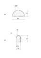
可撓性コード11の先端において、リンク機構22により開閉駆動される一対からなる鉗子片は、図2及び図3に示した両鉗子片20,20では、同じ形状であったものに対して、図7及び図8に示した鉗子片120U,120Lにおいて、その内面を構成する鋸歯状凹凸部120Ua,120Laにおける凸部Tと凹部R(図8)とは、軸線方向に半ピッチ分ずれており、従って鉗子片120U,120Lを閉状態にすると、図7に示したように、一方側の凸部Tが他方側の凹部Rに入り込むようになって、ほぼ全面で当接することになる。つまり、鉗子片120Uと鉗子片120Lとの内面は、それぞれに凹凸が存在するにも拘わらず、軸線方向における全長にわたってほぼ等しい距離となっている。 The pair of forceps pieces that are opened and closed by the
また、図9及び図10に示したように、両鉗子片120U,120Lの鋸歯状凹凸部120Ua,120Laとなっている内面は可撓性コード11の直径の半分以下となっている。ただし、可撓性コード11の直径の1/6より大きくなっている。そして、この内面から反対側の面、つまり外面120Ub,120Lbに向けて連続的に幅寸法が大きくなり、鉗子片120U,120Lの側面はテーパ形状の傾斜面となっている。ここで、外面120Ub,120Lbと鋸歯状凹凸部120Ua,120Laからなる内面との寸法差は、外面側が2倍程度となるように設定されている。そして、鉗子片120U,120Lにおいても、その鋸歯状凹凸部120Ua,120La以外は、外面120Ub,120Lbを含めて全体が絶縁被覆されている。 Further, as shown in FIGS. 9 and 10, the inner surfaces of the two forceps pieces 120 </ b> U and 120 </ b> L that are the serrated uneven portions 120 </ b> Ua and 120 </ b> La are less than half the diameter of the
以上のように構成することによって、止血のために、体内組織の出血している部位を両鉗子片120U,120L間で挟持したときに、両方の鋸歯状凹凸部120Ua,120Laがほぼ同じ距離関係となり、かつ体内組織に対する押圧力も全体に均等になるので、焼灼による凝固は広い範囲において均一に行われる。また、鉗子片120U,120Lの閉鎖時には、凹凸部120Ua,120Laが当接するようになるので、体内組織の切開もより効率的に行うことができる。 By configuring as described above, when the bleeding part of the body tissue is clamped between the two
しかも、鉗子片120U,120Lは、両外面側120Ub,120Lbが幅方向の厚みが大きくなっているので、基端側が支軸21に連結されて、片持ち状態となっている鉗子片120U,120Lの強度を高くしている。従って、体内組織に対する把持時に変形したりすることがなく、大きな把持力を作用させることができ、その作動の安定性、体内組織等の把持能力の向上が図られる。そして、両鉗子片120U,120Lは、鋸歯状凹凸部120Ua,120La以外の部位は絶縁被覆されているので、両側面が外面120Ub,120Lb側に向けて広がるように傾斜していても、高周波電流を流したときに、この傾斜面に当接している体内組織等が焼灼されることはない。 In addition, the
1 鉗子 2 高周波電源
10 鉗子本体 11 可撓性コード
12 ハンドル部 20,120U,120L 鉗子片
20a,120Ua,120La 鋸歯状凹凸部
120Ub,120Lb 外面 30 コイルスリーブ
31 絶縁チューブ 33 操作ワイヤ
40 軸部 41 スライダ
44 スライド駒 45 端子部DESCRIPTION OF SYMBOLS 1
Claims (5)
Translated fromJapanese内面に全長に及ぶように鋸歯状凹凸部が形成され、相互に開閉可能な一対の鉗子片を備え、閉鎖時にはそれらの内面が少なくとも部分的に当接するようになった鉗子本体と、
前記鉗子本体に連結して設けられ、この鉗子本体を構成する前記一対の鉗子片を開閉動作させるために、操作力伝達手段を挿通させた可撓性コードからなる挿入部材と、
前記挿入部材の基端部に連結され、前記一対の鉗子片を開閉操作するためのハンドル部とからなり、
前記両鉗子片は、導電性部材で形成されて、前記挿入部材の外径より小さい幅寸法を有する導電性部材で形成されて、高周波電源と電気的に接続された鋸歯状凹凸部となっており、
前記両鉗子片の幅寸法は、前記鋸歯状凹凸部を形成した内面の幅寸法を前記挿入部材の外径寸法の1/2乃至1/6となし、前記内面から、この内面とは反対側の外面に向けて連続的に幅寸法を大きくするように側面をテーパ形状とした傾斜面となし、
前記両鉗子片の外部に露出している面のうち、前記内面の前記鋸歯状凹凸部以外を絶縁被覆する
構成としたことを特徴とする高周波処置具。A high-frequency treatment instrument with a forceps mechanism inserted into a treatment instrument insertion channel of an endoscope or a trocar for a treatment instrument,
A forceps main body having a pair of forceps pieces that are formed to have a serrated unevenness on the inner surface so as to cover the entire length and that can be opened and closed with each other, and whose inner surfaces are at least partially abutted when closed,
An insertion member made of a flexible cord, which is provided in connection with the forceps main body and has an operating force transmission means inserted therein to open and close the pair of forceps pieces constituting the forceps main body;
It is connected to the base end portion of the insertion member, and comprises a handle portion for opening and closing the pair of forceps pieces,
Both the forceps pieces are formed of a conductive member, and are formed of a conductive member having a width smaller than the outer diameter of the insertion member, thereby forming a serrated uneven portion electrically connected to a high-frequency power source. And
The width dimension of both the forceps pieces is such that the width dimension of the inner surface on which the serrated irregularities are formed is 1/2 to 1/6 of the outer diameter dimension of the insertion member, and the inner surface is opposite to the inner surface. There is an inclined surface with a tapered side so that the width dimension is continuously increased toward the outer surface of
Of the surfaces exposed to the outside of the forceps pieces, the high-frequency treatment instrument is configured to insulate the inner surface other than the serrated irregularities.
Priority Applications (1)
| Application Number | Priority Date | Filing Date | Title |
|---|---|---|---|
| JP2013020435AJP5636449B2 (en) | 2007-05-25 | 2013-02-05 | High frequency treatment tool |
Applications Claiming Priority (3)
| Application Number | Priority Date | Filing Date | Title |
|---|---|---|---|
| JP2007138823 | 2007-05-25 | ||
| JP2007138823 | 2007-05-25 | ||
| JP2013020435AJP5636449B2 (en) | 2007-05-25 | 2013-02-05 | High frequency treatment tool |
Related Parent Applications (1)
| Application Number | Title | Priority Date | Filing Date |
|---|---|---|---|
| JP2008121850ADivisionJP2009006128A (en) | 2007-05-25 | 2008-05-08 | High-frequency treatment instrument |
Publications (2)
| Publication Number | Publication Date |
|---|---|
| JP2013078687Atrue JP2013078687A (en) | 2013-05-02 |
| JP5636449B2 JP5636449B2 (en) | 2014-12-03 |
Family
ID=39643050
Family Applications (2)
| Application Number | Title | Priority Date | Filing Date |
|---|---|---|---|
| JP2008121850APendingJP2009006128A (en) | 2007-05-25 | 2008-05-08 | High-frequency treatment instrument |
| JP2013020435AActiveJP5636449B2 (en) | 2007-05-25 | 2013-02-05 | High frequency treatment tool |
Family Applications Before (1)
| Application Number | Title | Priority Date | Filing Date |
|---|---|---|---|
| JP2008121850APendingJP2009006128A (en) | 2007-05-25 | 2008-05-08 | High-frequency treatment instrument |
Country Status (4)
| Country | Link |
|---|---|
| US (1) | US20080294159A1 (en) |
| EP (1) | EP1994904B1 (en) |
| JP (2) | JP2009006128A (en) |
| CN (1) | CN101310685B (en) |
Cited By (1)
| Publication number | Priority date | Publication date | Assignee | Title |
|---|---|---|---|---|
| JP2019047959A (en)* | 2017-09-11 | 2019-03-28 | 住友ベークライト株式会社 | Distal end treatment tool for high-frequency treatment instrument and medical high-frequency treatment instrument |
Families Citing this family (83)
| Publication number | Priority date | Publication date | Assignee | Title |
|---|---|---|---|---|
| US7364577B2 (en) | 2002-02-11 | 2008-04-29 | Sherwood Services Ag | Vessel sealing system |
| WO2005050151A1 (en) | 2003-10-23 | 2005-06-02 | Sherwood Services Ag | Thermocouple measurement circuit |
| US7396336B2 (en) | 2003-10-30 | 2008-07-08 | Sherwood Services Ag | Switched resonant ultrasonic power amplifier system |
| US7367976B2 (en) | 2003-11-17 | 2008-05-06 | Sherwood Services Ag | Bipolar forceps having monopolar extension |
| US7655004B2 (en) | 2007-02-15 | 2010-02-02 | Ethicon Endo-Surgery, Inc. | Electroporation ablation apparatus, system, and method |
| US7815662B2 (en) | 2007-03-08 | 2010-10-19 | Ethicon Endo-Surgery, Inc. | Surgical suture anchors and deployment device |
| US8075572B2 (en) | 2007-04-26 | 2011-12-13 | Ethicon Endo-Surgery, Inc. | Surgical suturing apparatus |
| US8100922B2 (en) | 2007-04-27 | 2012-01-24 | Ethicon Endo-Surgery, Inc. | Curved needle suturing tool |
| US8262655B2 (en) | 2007-11-21 | 2012-09-11 | Ethicon Endo-Surgery, Inc. | Bipolar forceps |
| US8579897B2 (en) | 2007-11-21 | 2013-11-12 | Ethicon Endo-Surgery, Inc. | Bipolar forceps |
| WO2009032623A2 (en)* | 2007-08-31 | 2009-03-12 | Ethicon Endo-Surgery, Inc | Electrical albation surgical instruments |
| US8568410B2 (en) | 2007-08-31 | 2013-10-29 | Ethicon Endo-Surgery, Inc. | Electrical ablation surgical instruments |
| US8480657B2 (en) | 2007-10-31 | 2013-07-09 | Ethicon Endo-Surgery, Inc. | Detachable distal overtube section and methods for forming a sealable opening in the wall of an organ |
| US20090112059A1 (en) | 2007-10-31 | 2009-04-30 | Nobis Rudolph H | Apparatus and methods for closing a gastrotomy |
| US8262680B2 (en) | 2008-03-10 | 2012-09-11 | Ethicon Endo-Surgery, Inc. | Anastomotic device |
| JP5380705B2 (en) | 2008-05-15 | 2014-01-08 | 株式会社リバーセイコー | Endoscopic high frequency hemostatic forceps |
| US8114072B2 (en) | 2008-05-30 | 2012-02-14 | Ethicon Endo-Surgery, Inc. | Electrical ablation device |
| US8317806B2 (en) | 2008-05-30 | 2012-11-27 | Ethicon Endo-Surgery, Inc. | Endoscopic suturing tension controlling and indication devices |
| US8652150B2 (en) | 2008-05-30 | 2014-02-18 | Ethicon Endo-Surgery, Inc. | Multifunction surgical device |
| US8771260B2 (en) | 2008-05-30 | 2014-07-08 | Ethicon Endo-Surgery, Inc. | Actuating and articulating surgical device |
| US8070759B2 (en) | 2008-05-30 | 2011-12-06 | Ethicon Endo-Surgery, Inc. | Surgical fastening device |
| US8679003B2 (en) | 2008-05-30 | 2014-03-25 | Ethicon Endo-Surgery, Inc. | Surgical device and endoscope including same |
| US8906035B2 (en) | 2008-06-04 | 2014-12-09 | Ethicon Endo-Surgery, Inc. | Endoscopic drop off bag |
| US8403926B2 (en) | 2008-06-05 | 2013-03-26 | Ethicon Endo-Surgery, Inc. | Manually articulating devices |
| US8361112B2 (en) | 2008-06-27 | 2013-01-29 | Ethicon Endo-Surgery, Inc. | Surgical suture arrangement |
| US8262563B2 (en) | 2008-07-14 | 2012-09-11 | Ethicon Endo-Surgery, Inc. | Endoscopic translumenal articulatable steerable overtube |
| US8888792B2 (en) | 2008-07-14 | 2014-11-18 | Ethicon Endo-Surgery, Inc. | Tissue apposition clip application devices and methods |
| JP5371309B2 (en) | 2008-07-23 | 2013-12-18 | オリンパスメディカルシステムズ株式会社 | High frequency treatment tool |
| US8211125B2 (en) | 2008-08-15 | 2012-07-03 | Ethicon Endo-Surgery, Inc. | Sterile appliance delivery device for endoscopic procedures |
| US8529563B2 (en) | 2008-08-25 | 2013-09-10 | Ethicon Endo-Surgery, Inc. | Electrical ablation devices |
| US8241204B2 (en) | 2008-08-29 | 2012-08-14 | Ethicon Endo-Surgery, Inc. | Articulating end cap |
| US8480689B2 (en) | 2008-09-02 | 2013-07-09 | Ethicon Endo-Surgery, Inc. | Suturing device |
| US8409200B2 (en) | 2008-09-03 | 2013-04-02 | Ethicon Endo-Surgery, Inc. | Surgical grasping device |
| US8114119B2 (en) | 2008-09-09 | 2012-02-14 | Ethicon Endo-Surgery, Inc. | Surgical grasping device |
| US8337394B2 (en) | 2008-10-01 | 2012-12-25 | Ethicon Endo-Surgery, Inc. | Overtube with expandable tip |
| US8142473B2 (en) | 2008-10-03 | 2012-03-27 | Tyco Healthcare Group Lp | Method of transferring rotational motion in an articulating surgical instrument |
| US8157834B2 (en) | 2008-11-25 | 2012-04-17 | Ethicon Endo-Surgery, Inc. | Rotational coupling device for surgical instrument with flexible actuators |
| US8172772B2 (en) | 2008-12-11 | 2012-05-08 | Ethicon Endo-Surgery, Inc. | Specimen retrieval device |
| US8361066B2 (en) | 2009-01-12 | 2013-01-29 | Ethicon Endo-Surgery, Inc. | Electrical ablation devices |
| US8828031B2 (en) | 2009-01-12 | 2014-09-09 | Ethicon Endo-Surgery, Inc. | Apparatus for forming an anastomosis |
| US8262652B2 (en) | 2009-01-12 | 2012-09-11 | Tyco Healthcare Group Lp | Imaginary impedance process monitoring and intelligent shut-off |
| US8252057B2 (en) | 2009-01-30 | 2012-08-28 | Ethicon Endo-Surgery, Inc. | Surgical access device |
| US9226772B2 (en) | 2009-01-30 | 2016-01-05 | Ethicon Endo-Surgery, Inc. | Surgical device |
| US8037591B2 (en) | 2009-02-02 | 2011-10-18 | Ethicon Endo-Surgery, Inc. | Surgical scissors |
| EP2430999B1 (en)* | 2009-05-13 | 2017-11-01 | Sumitomo Bakelite Co., Ltd. | Hemostatic forceps with a high-frequency electrode comprising a sawtooth portion |
| US9572621B2 (en)* | 2009-06-02 | 2017-02-21 | Bovie Medical Corporation | Surgical jaws for sealing tissue |
| US8246618B2 (en) | 2009-07-08 | 2012-08-21 | Tyco Healthcare Group Lp | Electrosurgical jaws with offset knife |
| HU229773B1 (en)* | 2009-09-02 | 2014-06-30 | A tool for surgical intervention | |
| WO2011033860A1 (en)* | 2009-09-15 | 2011-03-24 | オリンパスメディカルシステムズ株式会社 | Treatment instrument for endoscope |
| US20110098704A1 (en) | 2009-10-28 | 2011-04-28 | Ethicon Endo-Surgery, Inc. | Electrical ablation devices |
| US8608652B2 (en) | 2009-11-05 | 2013-12-17 | Ethicon Endo-Surgery, Inc. | Vaginal entry surgical devices, kit, system, and method |
| US8353487B2 (en) | 2009-12-17 | 2013-01-15 | Ethicon Endo-Surgery, Inc. | User interface support devices for endoscopic surgical instruments |
| US8496574B2 (en) | 2009-12-17 | 2013-07-30 | Ethicon Endo-Surgery, Inc. | Selectively positionable camera for surgical guide tube assembly |
| US9028483B2 (en) | 2009-12-18 | 2015-05-12 | Ethicon Endo-Surgery, Inc. | Surgical instrument comprising an electrode |
| US8506564B2 (en) | 2009-12-18 | 2013-08-13 | Ethicon Endo-Surgery, Inc. | Surgical instrument comprising an electrode |
| US9005198B2 (en) | 2010-01-29 | 2015-04-14 | Ethicon Endo-Surgery, Inc. | Surgical instrument comprising an electrode |
| JP4933684B2 (en)* | 2010-05-31 | 2012-05-16 | オリンパスメディカルシステムズ株式会社 | Endoscopic treatment tool |
| US8641712B2 (en)* | 2010-07-28 | 2014-02-04 | Covidien Lp | Local optimization of electrode current densities |
| US9113940B2 (en) | 2011-01-14 | 2015-08-25 | Covidien Lp | Trigger lockout and kickback mechanism for surgical instruments |
| US10092291B2 (en) | 2011-01-25 | 2018-10-09 | Ethicon Endo-Surgery, Inc. | Surgical instrument with selectively rigidizable features |
| US9233241B2 (en) | 2011-02-28 | 2016-01-12 | Ethicon Endo-Surgery, Inc. | Electrical ablation devices and methods |
| US9314620B2 (en) | 2011-02-28 | 2016-04-19 | Ethicon Endo-Surgery, Inc. | Electrical ablation devices and methods |
| US9254169B2 (en) | 2011-02-28 | 2016-02-09 | Ethicon Endo-Surgery, Inc. | Electrical ablation devices and methods |
| US9049987B2 (en) | 2011-03-17 | 2015-06-09 | Ethicon Endo-Surgery, Inc. | Hand held surgical device for manipulating an internal magnet assembly within a patient |
| US9844384B2 (en) | 2011-07-11 | 2017-12-19 | Covidien Lp | Stand alone energy-based tissue clips |
| US8986199B2 (en) | 2012-02-17 | 2015-03-24 | Ethicon Endo-Surgery, Inc. | Apparatus and methods for cleaning the lens of an endoscope |
| US9427255B2 (en) | 2012-05-14 | 2016-08-30 | Ethicon Endo-Surgery, Inc. | Apparatus for introducing a steerable camera assembly into a patient |
| US9529025B2 (en) | 2012-06-29 | 2016-12-27 | Covidien Lp | Systems and methods for measuring the frequency of signals generated by high frequency medical devices |
| US9078662B2 (en) | 2012-07-03 | 2015-07-14 | Ethicon Endo-Surgery, Inc. | Endoscopic cap electrode and method for using the same |
| US9545290B2 (en) | 2012-07-30 | 2017-01-17 | Ethicon Endo-Surgery, Inc. | Needle probe guide |
| US9572623B2 (en) | 2012-08-02 | 2017-02-21 | Ethicon Endo-Surgery, Inc. | Reusable electrode and disposable sheath |
| US10314649B2 (en) | 2012-08-02 | 2019-06-11 | Ethicon Endo-Surgery, Inc. | Flexible expandable electrode and method of intraluminal delivery of pulsed power |
| US9277957B2 (en) | 2012-08-15 | 2016-03-08 | Ethicon Endo-Surgery, Inc. | Electrosurgical devices and methods |
| US10098527B2 (en) | 2013-02-27 | 2018-10-16 | Ethidcon Endo-Surgery, Inc. | System for performing a minimally invasive surgical procedure |
| US9872719B2 (en) | 2013-07-24 | 2018-01-23 | Covidien Lp | Systems and methods for generating electrosurgical energy using a multistage power converter |
| US9655670B2 (en) | 2013-07-29 | 2017-05-23 | Covidien Lp | Systems and methods for measuring tissue impedance through an electrosurgical cable |
| US20150324317A1 (en) | 2014-05-07 | 2015-11-12 | Covidien Lp | Authentication and information system for reusable surgical instruments |
| CN106901803B (en)* | 2015-12-22 | 2020-11-24 | 深圳市第二人民医院 | A minimally invasive collagen membrane holder for tissue engineered cartilage transplantation |
| JP6216482B1 (en)* | 2016-02-02 | 2017-10-18 | オリンパス株式会社 | Endoscopic treatment tool |
| US11844562B2 (en) | 2020-03-23 | 2023-12-19 | Covidien Lp | Electrosurgical forceps for grasping, treating, and/or dividing tissue |
| US12226143B2 (en) | 2020-06-22 | 2025-02-18 | Covidien Lp | Universal surgical footswitch toggling |
| CN112315576A (en)* | 2020-11-02 | 2021-02-05 | 山东威高手术机器人有限公司 | Bipolar electric energy forceps head for minimally invasive surgical instrument |
| CN114391894A (en)* | 2021-12-10 | 2022-04-26 | 美科特医疗科技(苏州)有限公司 | Power mechanism of end effector |
Citations (2)
| Publication number | Priority date | Publication date | Assignee | Title |
|---|---|---|---|---|
| WO2005110264A2 (en)* | 2004-05-14 | 2005-11-24 | Erbe Elektromedizin Gmbh | Electrosurgical instrument |
| JP2006346417A (en)* | 2005-05-20 | 2006-12-28 | River Seiko:Kk | High frequency incision tool for endoscope |
Family Cites Families (15)
| Publication number | Priority date | Publication date | Assignee | Title |
|---|---|---|---|---|
| US1586645A (en)* | 1925-07-06 | 1926-06-01 | Bierman William | Method of and means for treating animal tissue to coagulate the same |
| IL73079A (en)* | 1984-09-26 | 1989-01-31 | Porat Michael | Gripper means for medical instruments |
| US5330471A (en)* | 1991-06-07 | 1994-07-19 | Hemostatic Surgery Corporation | Bi-polar electrosurgical endoscopic instruments and methods of use |
| US5433725A (en)* | 1991-12-13 | 1995-07-18 | Unisurge, Inc. | Hand-held surgical device and tools for use therewith, assembly and method |
| US5620459A (en)* | 1992-04-15 | 1997-04-15 | Microsurge, Inc. | Surgical instrument |
| DE69530642T2 (en)* | 1994-07-29 | 2004-04-01 | Olympus Optical Co., Ltd. | Medical instrument for use in combination with endoscopes |
| JPH08131448A (en)* | 1994-11-11 | 1996-05-28 | Olympus Optical Co Ltd | Treating device for endoscope |
| AU3583397A (en)* | 1996-06-27 | 1998-01-14 | Hank H. Chen | Transcervical electroocclusive sterilization device |
| US20030014052A1 (en)* | 1997-11-14 | 2003-01-16 | Buysse Steven P. | Laparoscopic bipolar electrosurgical instrument |
| JP3610306B2 (en)* | 2000-07-05 | 2005-01-12 | オリンパス株式会社 | High frequency treatment tool |
| US20020111624A1 (en)* | 2001-01-26 | 2002-08-15 | Witt David A. | Coagulating electrosurgical instrument with tissue dam |
| US7101371B2 (en)* | 2001-04-06 | 2006-09-05 | Dycus Sean T | Vessel sealer and divider |
| WO2004039416A2 (en)* | 2002-10-29 | 2004-05-13 | Tissuelink Medical, Inc. | Fluid-assisted electrosurgical scissors and methods |
| DE102004031141A1 (en)* | 2004-06-28 | 2006-01-26 | Erbe Elektromedizin Gmbh | Electrosurgical instrument |
| DE102006023696B4 (en)* | 2005-05-20 | 2019-10-17 | Kaneka Corporation | High-frequency incision instrument for an endoscope |
- 2008
- 2008-05-08JPJP2008121850Apatent/JP2009006128A/enactivePending
- 2008-05-23CNCN2008101091587Apatent/CN101310685B/enactiveActive
- 2008-05-23USUS12/153,768patent/US20080294159A1/ennot_activeAbandoned
- 2008-05-23EPEP08009510.2Apatent/EP1994904B1/enactiveActive
- 2013
- 2013-02-05JPJP2013020435Apatent/JP5636449B2/enactiveActive
Patent Citations (3)
| Publication number | Priority date | Publication date | Assignee | Title |
|---|---|---|---|---|
| WO2005110264A2 (en)* | 2004-05-14 | 2005-11-24 | Erbe Elektromedizin Gmbh | Electrosurgical instrument |
| JP2007536958A (en)* | 2004-05-14 | 2007-12-20 | エルベ エレクトロメディツィン ゲーエムベーハー | Electrosurgical instrument |
| JP2006346417A (en)* | 2005-05-20 | 2006-12-28 | River Seiko:Kk | High frequency incision tool for endoscope |
Cited By (2)
| Publication number | Priority date | Publication date | Assignee | Title |
|---|---|---|---|---|
| JP2019047959A (en)* | 2017-09-11 | 2019-03-28 | 住友ベークライト株式会社 | Distal end treatment tool for high-frequency treatment instrument and medical high-frequency treatment instrument |
| JP7000754B2 (en) | 2017-09-11 | 2022-01-19 | 住友ベークライト株式会社 | Advanced treatment tool for high frequency treatment tool and high frequency treatment tool for medical use |
Also Published As
| Publication number | Publication date |
|---|---|
| US20080294159A1 (en) | 2008-11-27 |
| EP1994904B1 (en) | 2017-05-10 |
| CN101310685B (en) | 2010-12-01 |
| JP5636449B2 (en) | 2014-12-03 |
| EP1994904A1 (en) | 2008-11-26 |
| JP2009006128A (en) | 2009-01-15 |
| CN101310685A (en) | 2008-11-26 |
Similar Documents
| Publication | Publication Date | Title |
|---|---|---|
| JP5636449B2 (en) | High frequency treatment tool | |
| JP4509722B2 (en) | Endoscopic mucosal resection device with conductive tissue stopper and method of using the same | |
| JP4546424B2 (en) | Endoscopic treatment tool | |
| JP3655664B2 (en) | High frequency knife | |
| JP4578912B2 (en) | Endoscopic mucosal resection device with overtube and method of using the same | |
| US7972333B2 (en) | High frequency incision tool for endoscope | |
| KR100595803B1 (en) | High-frequency knife and endoscopic apparatus | |
| JP4652004B2 (en) | Endoscopic mucosal resection device | |
| US20170325876A1 (en) | High frequency forceps | |
| JPH11285502A (en) | High frequency treatment tool for endoscope | |
| JP2009112788A (en) | High frequency tool | |
| JP2003299667A (en) | Bipolar high-frequency incision instrument for endoscope | |
| JP2011212315A (en) | High frequency treatment instrument for endoscope | |
| US20070282336A1 (en) | Bipolar high-frequency treatment tool for endoscope | |
| JP4296141B2 (en) | Endoscopic high-frequency treatment instrument | |
| JP2003210483A (en) | High frequency tissue incision instrument | |
| JP4461206B2 (en) | Endoscopic high-frequency incision tool | |
| JP5535862B2 (en) | High frequency peeling knife device for endoscope | |
| JP2009254650A (en) | High-frequency treatment instrument | |
| JP2009119218A (en) | Endoscopic hook-type high-frequency treatment instrument | |
| JP2001061848A (en) | High frequency treatment apparatus | |
| JP4476229B2 (en) | Bipolar saddle-shaped high-frequency treatment instrument for endoscope | |
| JP4085148B2 (en) | High frequency snare | |
| EP3031420B1 (en) | Energizable attachment for surgical devices | |
| CN107736936A (en) | The bipolar jaw type cutting ablation knife of throat |
Legal Events
| Date | Code | Title | Description |
|---|---|---|---|
| A621 | Written request for application examination | Free format text:JAPANESE INTERMEDIATE CODE: A621 Effective date:20130205 | |
| RD01 | Notification of change of attorney | Free format text:JAPANESE INTERMEDIATE CODE: A7421 Effective date:20130226 | |
| A521 | Request for written amendment filed | Free format text:JAPANESE INTERMEDIATE CODE: A821 Effective date:20130226 | |
| A977 | Report on retrieval | Free format text:JAPANESE INTERMEDIATE CODE: A971007 Effective date:20131115 | |
| A131 | Notification of reasons for refusal | Free format text:JAPANESE INTERMEDIATE CODE: A131 Effective date:20131211 | |
| A02 | Decision of refusal | Free format text:JAPANESE INTERMEDIATE CODE: A02 Effective date:20140402 | |
| A521 | Request for written amendment filed | Free format text:JAPANESE INTERMEDIATE CODE: A523 Effective date:20140701 | |
| A911 | Transfer to examiner for re-examination before appeal (zenchi) | Free format text:JAPANESE INTERMEDIATE CODE: A911 Effective date:20140814 | |
| TRDD | Decision of grant or rejection written | ||
| A01 | Written decision to grant a patent or to grant a registration (utility model) | Free format text:JAPANESE INTERMEDIATE CODE: A01 Effective date:20141008 | |
| A61 | First payment of annual fees (during grant procedure) | Free format text:JAPANESE INTERMEDIATE CODE: A61 Effective date:20141020 | |
| R150 | Certificate of patent or registration of utility model | Ref document number:5636449 Country of ref document:JP Free format text:JAPANESE INTERMEDIATE CODE: R150 | |
| R250 | Receipt of annual fees | Free format text:JAPANESE INTERMEDIATE CODE: R250 | |
| R250 | Receipt of annual fees | Free format text:JAPANESE INTERMEDIATE CODE: R250 | |
| R250 | Receipt of annual fees | Free format text:JAPANESE INTERMEDIATE CODE: R250 | |
| R250 | Receipt of annual fees | Free format text:JAPANESE INTERMEDIATE CODE: R250 | |
| R250 | Receipt of annual fees | Free format text:JAPANESE INTERMEDIATE CODE: R250 | |
| R250 | Receipt of annual fees | Free format text:JAPANESE INTERMEDIATE CODE: R250 | |
| R250 | Receipt of annual fees | Free format text:JAPANESE INTERMEDIATE CODE: R250 | |
| R250 | Receipt of annual fees | Free format text:JAPANESE INTERMEDIATE CODE: R250 | |
| R250 | Receipt of annual fees | Free format text:JAPANESE INTERMEDIATE CODE: R250 |