JP2013077560A - Method for manufacturing electrode for electrochemical element - Google Patents
Method for manufacturing electrode for electrochemical elementDownload PDFInfo
- Publication number
- JP2013077560A JP2013077560AJP2012201186AJP2012201186AJP2013077560AJP 2013077560 AJP2013077560 AJP 2013077560AJP 2012201186 AJP2012201186 AJP 2012201186AJP 2012201186 AJP2012201186 AJP 2012201186AJP 2013077560 AJP2013077560 AJP 2013077560A
- Authority
- JP
- Japan
- Prior art keywords
- roll
- electrode
- layer
- active material
- binder
- Prior art date
- Legal status (The legal status is an assumption and is not a legal conclusion. Google has not performed a legal analysis and makes no representation as to the accuracy of the status listed.)
- Pending
Links
Images


Classifications
- Y—GENERAL TAGGING OF NEW TECHNOLOGICAL DEVELOPMENTS; GENERAL TAGGING OF CROSS-SECTIONAL TECHNOLOGIES SPANNING OVER SEVERAL SECTIONS OF THE IPC; TECHNICAL SUBJECTS COVERED BY FORMER USPC CROSS-REFERENCE ART COLLECTIONS [XRACs] AND DIGESTS
- Y02—TECHNOLOGIES OR APPLICATIONS FOR MITIGATION OR ADAPTATION AGAINST CLIMATE CHANGE
- Y02E—REDUCTION OF GREENHOUSE GAS [GHG] EMISSIONS, RELATED TO ENERGY GENERATION, TRANSMISSION OR DISTRIBUTION
- Y02E60/00—Enabling technologies; Technologies with a potential or indirect contribution to GHG emissions mitigation
- Y02E60/10—Energy storage using batteries
Landscapes
- Electric Double-Layer Capacitors Or The Like (AREA)
- Fixed Capacitors And Capacitor Manufacturing Machines (AREA)
- Battery Electrode And Active Subsutance (AREA)
- Application Of Or Painting With Fluid Materials (AREA)
- Coating Apparatus (AREA)
Abstract
Description
Translated fromJapanese本発明は、リチウムイオン二次電池や鉛蓄電池などの二次電池や、電気二重層キャパシタやリチウムイオンキャパシタなどの電気化学素子に用いられる電極(以下、総称して「電気化学素子用電極」と記載することがある。)の製造方法に関する。より詳しくは、小型の生産設備で、低コストに、連続的に、電気容量の高い電気化学素子用電極を製造する方法に関する。 The present invention relates to electrodes used for secondary batteries such as lithium ion secondary batteries and lead storage batteries, and electrochemical elements such as electric double layer capacitors and lithium ion capacitors (hereinafter collectively referred to as “electrodes for electrochemical elements”). A manufacturing method of the same). More specifically, the present invention relates to a method for manufacturing an electrode for an electrochemical element having a high electric capacity continuously at a low cost with a small production facility.
電気化学素子用電極の製造方法としては、複合粒子を加圧成形して電極層を形成する方法が知られている。乾式法としては、例えば、特許文献1には、電極材料を定量フィーダーによって、略水平に配置された一対のプレス用ロールに供給し、必要に応じてこのプレス用ロールで電極材料をシート状成形体に成形する工程を含む電気化学素子用電極の製造方法が記載されている。プレス用ロールに供給された電極材料は、ロール上に載せているだけである。
また、特許文献2には、電極組成物層を長尺の支持体表面上に乾式法により形成し、それを巻き取り巻回体とし、次いで該巻回体から電極組成物層を引き出しながら集電体に圧着した後、支持体を電極組成物層から剥離して電気化学素子用電極を製造する方法が開示されている。As a method for producing an electrode for an electrochemical element, a method of forming an electrode layer by press-molding composite particles is known. As a dry method, for example, in
In
本発明の目的は、小型の生産設備で、低コストに、連続的に、電気容量の高い電気化学素子用電極を製造する方法を提供する事である。 An object of the present invention is to provide a method for continuously producing an electrode for an electrochemical element having a high electric capacity at a low cost with a small production facility.
本発明者は、複合粒子粉末を圧縮してロール面に付着させれば、支持体を必要とせず、連続的な生産ができ、生産設備の小型化ができる、電気容量の高い電気化学素子用電極が得られることを見出した。本発明は、これらの知見に基づいてさらに検討を進め、完成するに至ったものである。 The present inventor does not need a support if the composite particle powder is compressed and adhered to the roll surface, can be produced continuously, and the production equipment can be downsized. It has been found that an electrode can be obtained. The present invention has been further studied based on these findings and has been completed.
すなわち、本発明は以下の態様を含む。
(1)一対の逆方向に回転するロール間に、電極活物質および結着材を含有してなる複合粒子粉末を供給し、複合粒子粉末を圧縮して一方のロール面に付着させて圧粉層を形成する圧粉層形成工程、および ロールの一方に付着された圧粉層を長尺のシート状集電体に転写する転写工程、を有する電気化学素子用電極の製造方法、
(2)転写と同時に又は転写の後に、前記圧粉層を加圧する工程を更に有する、上記(1)に記載の電気化学素子用電極の製造方法、
(3)シート状集電体両面において、前記転写工程を同時に又は相前後して行う、上記(1)または(2)に記載の電気化学素子用電極の製造方法、
(4)圧粉層の付着するロールは、そのロール面が粗面化処理されたものである、上記(1)〜(3)のいずれか一つに記載の電気化学素子用電極の製造方法、
(5)ロールに付着している圧粉層の密度が、圧縮前の複合粒子粉末の密度の130%〜400%である、上記(1)〜(4)のいずれか一つに記載の電気化学素子用電極の製造方法、
(6)圧粉層の復元率が100%〜5000%である、上記(1)〜(5)のいずれか一つに記載の電気化学素子用電極の製造方法。That is, the present invention includes the following aspects.
(1) A composite particle powder containing an electrode active material and a binder is supplied between a pair of rolls rotating in opposite directions, and the composite particle powder is compressed and adhered to one of the roll surfaces. A method for producing an electrode for an electrochemical device, comprising: a dust layer forming step of forming a layer; and a transfer step of transferring the dust layer attached to one of the rolls to a long sheet-like current collector,
(2) The method for producing an electrode for an electrochemical element according to the above (1), further comprising a step of pressurizing the powder layer simultaneously with or after transfer.
(3) The method for producing an electrode for an electrochemical element according to (1) or (2), wherein the transfer step is performed simultaneously or sequentially on both surfaces of the sheet-like current collector,
(4) The method for producing an electrode for an electrochemical element according to any one of the above (1) to (3), wherein the roll to which the green compact layer is attached has a roll surface roughened. ,
(5) The electricity according to any one of the above (1) to (4), wherein the density of the dust layer adhering to the roll is 130% to 400% of the density of the composite particle powder before compression. Manufacturing method of electrode for chemical element,
(6) The method for producing an electrode for an electrochemical element according to any one of (1) to (5), wherein the restoration rate of the green compact layer is 100% to 5000%.
本発明によれば、小型の生産設備で、低コストに、連続的に、電気容量の高い電気化学素子用電極を製造する方法が提供される。 ADVANTAGE OF THE INVENTION According to this invention, the method of manufacturing the electrode for electrochemical elements with a high electrical capacity continuously with a small production equipment at low cost is provided.
以下、本発明に係る電気化学素子用電極の製造方法について、図面を参照しながら具体的に説明する。
本発明の製造方法は、一対の逆方向に回転するロール間に、電極活物質および結着材を含有してなる複合粒子粉末を供給し、複合粒子粉末を圧縮して一方のロール面に付着させて圧粉層を形成する圧粉層形成工程、およびロールの一方に付着された圧粉層を長尺のシート状集電体に転写する転写工程、を有するものである。そして、好ましくは、転写と同時にまたは転写の後に圧粉層を加圧する工程を更に有するものである。Hereinafter, the method for producing an electrode for an electrochemical device according to the present invention will be specifically described with reference to the drawings.
In the production method of the present invention, a composite particle powder containing an electrode active material and a binder is supplied between a pair of rolls rotating in opposite directions, and the composite particle powder is compressed and adhered to one roll surface. A compacting layer forming step of forming a compacted layer, and a transferring step of transferring the compacted layer attached to one of the rolls to a long sheet-shaped current collector. Preferably, the method further includes a step of pressurizing the dust layer simultaneously with the transfer or after the transfer.
(複合粒子)
本発明に用いられる複合粒子は、電極活物質および結着材を含有してなる。本発明でいう複合粒子とは、電極活物質、結着材、及びその他必要に応じて含まれてもよい材料等が集まって一体化した粒子を指す。(Composite particles)
The composite particles used in the present invention contain an electrode active material and a binder. The composite particle as used in the present invention refers to a particle in which an electrode active material, a binder, and other materials that may be included as necessary are gathered and integrated.
(電極活物質)
複合粒子に含有される電極活物質は、電気化学素子用電極内で電子の受け渡しをする物質である。電極活物質には主としてリチウムイオン二次電池用活物質、電気二重層キャパシタ用活物質やリチウムイオンキャパシタ用活物質がある。(Electrode active material)
The electrode active material contained in the composite particles is a substance that transfers electrons in the electrode for an electrochemical element. The electrode active material mainly includes an active material for a lithium ion secondary battery, an active material for an electric double layer capacitor, and an active material for a lithium ion capacitor.
又、リチウムイオン二次電池用電極活物質には、正極用、負極用がある。
リチウムイオン二次電池用正極活物質としては、リチウムイオンを可逆的にドープ・脱ドープ可能な金属酸化物が挙げられる。かかる金属酸化物としては、例えば、コバルト酸リチウム、ニッケル酸リチウム、マンガン酸リチウム、燐酸鉄リチウム、燐酸マンガンリチウム、燐酸バナジウムリチウム、バナジン酸鉄リチウム、ニッケル−マンガン−コバルト酸リチウム、ニッケル−コバルト酸リチウム、ニッケル−マンガン酸リチウム、鉄−マンガン酸リチウム、鉄−マンガン−コバルト酸リチウム、珪酸鉄リチウム、珪酸鉄−マンガンリチウム、酸化バナジウム、バナジン酸銅、酸化ニオブ、硫化チタン、酸化モリブデン、硫化モリブデン、等を挙げることができる。さらに、ポリアセチレン、ポリ−p−フェニレン、ポリキノンなどのポリマーが挙げられる。これらのうち、リチウム含有金属酸化物を用いることが好ましい。なお、上記にて例示した正極活物質は適宜用途に応じて単独で使用してもよく、複数種混合して使用してもよい。The electrode active material for lithium ion secondary batteries includes a positive electrode and a negative electrode.
Examples of the positive electrode active material for a lithium ion secondary battery include metal oxides capable of reversibly doping and dedoping lithium ions. Examples of the metal oxide include lithium cobaltate, lithium nickelate, lithium manganate, lithium iron phosphate, lithium manganese phosphate, lithium vanadium phosphate, lithium iron vanadate, nickel-manganese-lithium cobaltate, nickel-cobalt acid. Lithium, nickel-lithium manganate, iron-lithium manganate, iron-manganese-lithium cobaltate, lithium iron silicate, iron silicate-manganese lithium, vanadium oxide, copper vanadate, niobium oxide, titanium sulfide, molybdenum oxide, molybdenum sulfide , Etc. Furthermore, polymers such as polyacetylene, poly-p-phenylene and polyquinone can be mentioned. Of these, it is preferable to use a lithium-containing metal oxide. In addition, the positive electrode active material illustrated above may be used independently according to a use, and may be used in mixture of multiple types.
リチウムイオン二次電池用負極活物質としては、易黒鉛化性炭素、難黒鉛化性炭素、活性炭、熱分解炭素などの低結晶性炭素(非晶質炭素)、グラファイト(天然黒鉛、人造黒鉛)、カーボンナノウォール、カーボンナノチューブ、あるいはこれら物理的性質の異なる炭素の複合化炭素材料、錫やケイ素等の合金系材料、ケイ素酸化物、錫酸化物、バナジウム酸化物、チタン酸リチウム等の酸化物、ポリアセン等が挙げられる。なお、上記に例示した負極活物質は適宜用途に応じて単独で使用してもよく、複数種混合して使用してもよい。 Examples of negative electrode active materials for lithium ion secondary batteries include graphitizable carbon, non-graphitizable carbon, activated carbon, pyrolytic carbon, and other low-crystalline carbon (amorphous carbon), graphite (natural graphite, artificial graphite) Carbon nanowalls, carbon nanotubes, or composite carbon materials of carbons having different physical properties, alloy materials such as tin and silicon, oxides such as silicon oxide, tin oxide, vanadium oxide, and lithium titanate And polyacene. In addition, the negative electrode active material illustrated above may be used independently according to a use, and may be used in mixture of multiple types.
リチウムイオン二次電池用電極活物質の形状は、粒状に整粒されたものが好ましい。粒子の形状が球形であると、電極成形時により高密度な電極が形成できる。
リチウムイオン二次電池用電極活物質の体積平均粒子径は、正極用、負極用ともに通常0.1〜100μm、好ましくは0.5〜50μm、より好ましくは0.8〜20μmである。
リチウムイオン二次電池用電極活物質のタップ密度は、特に制限されないが、正極用では2g/cm3以上、負極用では0.6g/cm3以上のものが好適に用いられる。The shape of the electrode active material for a lithium ion secondary battery is preferably a granulated particle. When the shape of the particles is spherical, a higher density electrode can be formed during electrode molding.
The volume average particle diameter of the electrode active material for a lithium ion secondary battery is usually 0.1 to 100 μm, preferably 0.5 to 50 μm, more preferably 0.8 to 20 μm for both the positive electrode and the negative electrode.
The tap density of the electrode active material for a lithium ion secondary battery is not particularly limited, but preferably 2 g / cm3 or more for the positive electrode and 0.6 g / cm3 or more for the negative electrode.
リチウムイオンキャパシタ用電極活物質には、正極用と負極用がある。
リチウムイオンキャパシタ用正極活物質としては、アニオンおよび/またはカチオンを可逆的にドープ・脱ドープ可能な活性炭、ポリアセン系有機半導体(PAS)、カーボンナノチューブ、カーボンウィスカー、グラファイト等が挙げられる。中でも活性炭、カーボンナノチューブが好ましい。The electrode active material for lithium ion capacitors includes a positive electrode and a negative electrode.
Examples of the positive electrode active material for a lithium ion capacitor include activated carbon, polyacene organic semiconductor (PAS), carbon nanotube, carbon whisker, and graphite that can be reversibly doped and dedoped with anions and / or cations. Of these, activated carbon and carbon nanotubes are preferred.
リチウムイオンキャパシタ用負極活物質としては、リチウムイオン二次電池用負極活物質として例示した材料をいずれも使用することができる。 As the negative electrode active material for lithium ion capacitors, any of the materials exemplified as the negative electrode active material for lithium ion secondary batteries can be used.
リチウムイオンキャパシタ用電極活物質の体積平均粒子径は、通常0.1〜100μm、好ましくは0.5〜50μm、更に好ましくは0.8〜20μmである。
リチウムイオンキャパシタ用電極活物質として活性炭を用いる場合、活性炭の比表面積は、通常30m2/g以上、好ましくは500〜3,000m2/g、より好ましくは1,500〜2,600m2/gである。比表面積が約2,000m2/gまでは比表面積が大きくなるほど活性炭の単位重量あたりの静電容量は増加する傾向にあるが、それ以降は静電容量は然程増加せず、かえって電極層の密度が低下し、静電容量密度が低下する傾向にある。また、活性炭が有する細孔のサイズは電解質イオンのサイズに適合していることがリチウムイオンキャパシタとしての特徴である急速充放電特性の面で好ましい。従って、電極活物質を適宜選択することで、所望の容量密度、入出力特性を有する電極層を得ることができる。The volume average particle diameter of the electrode active material for lithium ion capacitors is usually 0.1 to 100 μm, preferably 0.5 to 50 μm, and more preferably 0.8 to 20 μm.
When activated carbon is used as the electrode active material for a lithium ion capacitor, the specific surface area of the activated carbon is usually 30 m2 / g or more, preferably 500 to 3,000 m2 / g, more preferably 1,500 to 2,600 m2 / g. It is. The specific surface area up to about 2,000 m2 / g tends to increase the capacitance per unit weight of the activated carbon as the specific surface area increases, but thereafter the capacitance does not increase so much. There is a tendency for the density to decrease and the capacitance density to decrease. Moreover, it is preferable in terms of rapid charge / discharge characteristics, which is a feature of a lithium ion capacitor, that the pore size of the activated carbon is compatible with the size of the electrolyte ion. Therefore, an electrode layer having desired capacity density and input / output characteristics can be obtained by appropriately selecting an electrode active material.
電気二重層キャパシタ用電極活物質としては、リチウムイオンキャパシタ用正極活物質として例示された材料を、正極用および負極用として使用することができる。中でも、活性炭が好ましい。 As the electrode active material for the electric double layer capacitor, materials exemplified as the positive electrode active material for the lithium ion capacitor can be used for the positive electrode and the negative electrode. Among these, activated carbon is preferable.
(結着材)
複合粒子に含有される結着材は、電極活物質を相互に結着させる物質である。好適な結着材は、溶媒に分散する性質のある分散型結着材である。分散型結着材としては、溶媒に分散する重合体を用いることができ、そのような重合体としては、例えば、シリコーン系重合体、フッ素系重合体、共役ジエン系重合体、アクリレート系重合体、ポリイミド、ポリアミド、ポリウレタン等の高分子化合物が挙げられ、フッ素系重合体、共役ジエン系重合体及びアクリレート系重合体が好ましく、共役ジエン系重合体及びアクリレート系重合体が、耐電圧を高くでき、かつ電気化学素子のエネルギー密度を高くすることができる点でより好ましい。(Binder)
The binder contained in the composite particles is a substance that binds the electrode active materials to each other. A suitable binder is a dispersion type binder having a property of being dispersed in a solvent. As the dispersion-type binder, a polymer dispersed in a solvent can be used. Examples of such a polymer include silicone polymers, fluorine polymers, conjugated diene polymers, and acrylate polymers. Polymer compounds such as polyimide, polyamide, polyurethane, etc., fluorine-based polymers, conjugated diene-based polymers and acrylate-based polymers are preferable, and conjugated diene-based polymers and acrylate-based polymers can increase withstand voltage. And it is more preferable at the point which can make the energy density of an electrochemical element high.
共役ジエン系重合体は、共役ジエンの単独重合体もしくは共役ジエンを含む単量体混合物を重合して得られる共重合体、またはそれらの水素添加物である。前記単量体混合物における共役ジエンの割合は通常40重量%以上、好ましくは50重量%以上、より好ましくは60重量%以上である。共役ジエン系重合体の具体例としては、ポリブタジエンやポリイソプレンなどの共役ジエン単独重合体;カルボキシ変性されていてもよいスチレン・ブタジエン共重合体(SBR)などの芳香族ビニル・共役ジエン共重合体;アクリロニトリル・ブタジエン共重合体(NBR)などのシアン化ビニル・共役ジエン共重合体;水素化SBR、水素化NBR等が挙げられる。 The conjugated diene polymer is a homopolymer of a conjugated diene or a copolymer obtained by polymerizing a monomer mixture containing a conjugated diene, or a hydrogenated product thereof. The proportion of the conjugated diene in the monomer mixture is usually 40% by weight or more, preferably 50% by weight or more, more preferably 60% by weight or more. Specific examples of conjugated diene polymers include conjugated diene homopolymers such as polybutadiene and polyisoprene; aromatic vinyl / conjugated diene copolymers such as carboxy-modified styrene / butadiene copolymer (SBR) A vinyl cyanide / conjugated diene copolymer such as acrylonitrile / butadiene copolymer (NBR); hydrogenated SBR, hydrogenated NBR, and the like.
アクリレート系重合体は、一般式(1):CH2=CR1−COOR2(式中、R1は水素原子またはメチル基を、R2はアルキル基またはシクロアルキル基を表す。R2はさらにエーテル基、水酸基、カルボン酸基、フッ素基、リン酸基、エポキシ基、アミノ基を有していてもよい。)で表される化合物由来の単量体単位を含む重合体、具体的には、一般式(1)で表される化合物の単独重合体、または前記一般式(1)で表される化合物を含む単量体混合物を重合して得られる共重合体である。一般式(1)で表される化合物の具体例としては、(メタ)アクリル酸メチル、(メタ)アクリル酸エチル、(メタ)アクリル酸プロピル、(メタ)アクリル酸イソプロピル、(メタ)アクリル酸n−ブチル、(メタ)アクリル酸イソブチル、(メタ)アクリル酸シクロヘキシル、(メタ)アクリル酸2−エチルヘキシル、(メタ)アクリル酸イソペンチル、(メタ)アクリル酸イソオクチル、(メタ)アクリル酸イソボニル、(メタ)アクリル酸イソデシル、(メタ)アクリル酸ラウリル、(メタ)アクリル酸ステアリル、および(メタ)アクリル酸トリデシル等の(メタ)アクリル酸アルキルエステル;(メタ)アクリル酸ブトキシエチル、(メタ)アクリル酸エトキシジエチレングリコール、(メタ)アクリル酸メトキシジプロピレングリコール、(メタ)アクリル酸メトキシポリエチレングリコール、(メタ)アクリル酸フェノキシエチル、(メタ)アクリル酸テトラヒドロフルフリル等のエーテル基含有(メタ)アクリル酸エステル;(メタ)アクリル酸−2−ヒドロキシエチル、(メタ)アクリル酸−2−ヒドロキシプロピル、(メタ)アクリル酸−2−ヒドロキシ−3−フェノキシプロピル、2−(メタ)アクリロイロキシエチル−2−ヒドロキシエチルフタル酸等の水酸基含有(メタ)アクリル酸エステル;2−(メタ)アクリロイロキシエチルフタル酸、2−(メタ)アクリロイロキシエチルフタル酸等のカルボン酸含有(メタ)アクリル酸エステル;(メタ)アクリル酸パーフロロオクチルエチル等のフッ素基含有(メタ)アクリル酸エステル;(メタ)アクリル酸リン酸エチル等のリン酸基含有(メタ)アクリル酸エステル;(メタ)アクリル酸グリシジル等のエポキシ基含有(メタ)アクリル酸エステル;(メタ)アクリル酸ジメチルアミノエチル等のアミノ基含有(メタ)アクリル酸エステル;等が挙げられる。
これら(メタ)アクリル酸エステルは、それぞれ単独で、あるいは2種以上を組み合わせて用いることができる。これらの中でも、(メタ)アクリル酸アルキルエステルが好ましく、(メタ)アクリル酸メチル、(メタ)アクリル酸エチル、および(メタ)アクリル酸n―ブチルやアルキル基の炭素数が6〜12である(メタ)アクリル酸アルキルエステルがより好ましい。これらを選択することにより、電解液に対する膨潤性を低くすることが可能となり、サイクル特性を向上させることができる。The acrylate polymer has the general formula (1): CH2 ═CR1 —COOR2 (wherein R1 represents a hydrogen atom or a methyl group, R2 represents an alkyl group or a cycloalkyl group. R2 further represents An ether group, a hydroxyl group, a carboxylic acid group, a fluorine group, a phosphoric acid group, an epoxy group, and an amino group.), A polymer containing a monomer unit derived from a compound represented by , A homopolymer of the compound represented by the general formula (1), or a copolymer obtained by polymerizing a monomer mixture containing the compound represented by the general formula (1). Specific examples of the compound represented by the general formula (1) include methyl (meth) acrylate, ethyl (meth) acrylate, propyl (meth) acrylate, isopropyl (meth) acrylate, and (meth) acrylate n. -Butyl, isobutyl (meth) acrylate, cyclohexyl (meth) acrylate, 2-ethylhexyl (meth) acrylate, isopentyl (meth) acrylate, isooctyl (meth) acrylate, isobornyl (meth) acrylate, (meth) (Meth) acrylic acid alkyl esters such as isodecyl acrylate, lauryl (meth) acrylate, stearyl (meth) acrylate, and tridecyl (meth) acrylate; butoxyethyl (meth) acrylate, ethoxydiethylene glycol (meth) acrylate , (Meth) acrylic acid methoxydipropylene Recall, (meth) acrylic acid methoxypolyethylene glycol, (meth) acrylic acid phenoxyethyl, (meth) acrylic acid tetrahydrofurfuryl ether group-containing (meth) acrylic acid ester; (meth) acrylic acid-2-hydroxyethyl, Hydroxyl-containing (meth) acrylic such as (meth) acrylic acid-2-hydroxypropyl, (meth) acrylic acid-2-hydroxy-3-phenoxypropyl, 2- (meth) acryloyloxyethyl-2-hydroxyethylphthalic acid Acid ester; 2- (meth) acryloyloxyethylphthalic acid, carboxylic acid-containing (meth) acrylic acid ester such as 2- (meth) acryloyloxyethylphthalic acid; Fluorine such as perfluorooctylethyl (meth) acrylate Group-containing (meth) acrylic acid ester; Phosphoric acid group-containing (meth) acrylic acid esters such as ethyl phosphate; Epoxy group-containing (meth) acrylic acid esters such as glycidyl (meth) acrylate; Amino group content such as dimethylaminoethyl (meth) acrylate ( (Meth) acrylic acid ester; and the like.
These (meth) acrylic acid esters can be used alone or in combination of two or more. Among these, (meth) acrylic acid alkyl ester is preferable, and (meth) acrylic acid methyl, (meth) acrylic acid ethyl, and (meth) acrylic acid n-butyl and alkyl groups have 6 to 12 carbon atoms ( More preferred are (meth) acrylic acid alkyl esters. By selecting these, it becomes possible to reduce the swellability with respect to the electrolytic solution, and to improve the cycle characteristics.
さらに、アクリレート系重合体においては、例えば、2つ以上の炭素−炭素二重結合を有するカルボン酸エステル類、芳香族ビニル系単量体、アミド系単量体、オレフィン類、ジエン系単量体、ビニルケトン類、複素環含有ビニル化合物などの、共重合可能な単量体を共重合させることができる。また、α,β−不飽和ニトリル化合物や酸成分を有するビニル化合物を共重合させることができる。 Furthermore, in the acrylate polymer, for example, carboxylic acid esters having two or more carbon-carbon double bonds, aromatic vinyl monomers, amide monomers, olefins, diene monomers , Vinyl ketones, heterocycle-containing vinyl compounds, and the like can be copolymerized. Further, an α, β-unsaturated nitrile compound or a vinyl compound having an acid component can be copolymerized.
アクリレート系重合体中における(メタ)アクリル酸エステル単位の含有割合は、好ましくは50〜95重量%であり、より好ましくは60〜90重量%である。(メタ)アクリル酸エステル単位の含有割合を上記範囲とすることにより、電極とした際における柔軟性を向上させることができ、割れに対する耐性を高いものとすることができる。 The content ratio of the (meth) acrylic acid ester unit in the acrylate polymer is preferably 50 to 95% by weight, more preferably 60 to 90% by weight. By setting the content ratio of the (meth) acrylic acid ester unit in the above range, the flexibility in forming the electrode can be improved, and the resistance to cracking can be increased.
α,β−不飽和ニトリル化合物としては、アクリロニトリル、メタクリロニトリル、α−クロロアクリロニトリル、α−ブロモアクリロニトリルなどが挙げられる。これらは、それぞれ単独で、あるいは2種以上を組み合わせて用いることができる。これらの中でも、アクリロニトリル、メタクリロニトリルが好ましく、アクリロニトリルがより好ましい。
アクリレート系重合体中におけるα,β−不飽和ニトリル化合物単位の含有割合は、通常0.1〜40重量%、好ましくは0.5〜30重量%、より好ましくは1〜20重量%の範囲である。α,β−不飽和ニトリル化合物単位の含有割合を上記範囲とすることにより、結着材としての結着力をより高めることができる。Examples of the α, β-unsaturated nitrile compound include acrylonitrile, methacrylonitrile, α-chloroacrylonitrile, α-bromoacrylonitrile and the like. These may be used alone or in combination of two or more. Among these, acrylonitrile and methacrylonitrile are preferable, and acrylonitrile is more preferable.
The content ratio of the α, β-unsaturated nitrile compound unit in the acrylate polymer is usually 0.1 to 40% by weight, preferably 0.5 to 30% by weight, more preferably 1 to 20% by weight. is there. By setting the content ratio of the α, β-unsaturated nitrile compound unit in the above range, the binding force as the binder can be further increased.
酸成分を有するビニル化合物としては、アクリル酸、メタクリル酸、イタコン酸、マレイン酸、フマル酸などが挙げられる。これらは、それぞれ単独で、あるいは2種以上を組み合わせて用いることができる。これらの中でも、アクリル酸、メタクリル酸、イタコン酸が好ましく、メタクリル酸、イタコン酸がより好ましく、特に、メタクリル酸とイタコン酸とを併用して用いることが好ましい。
アクリレート系重合体中における酸成分を有するビニル化合物単位の含有割合は、好ましくは1.0〜10重量%であり、より好ましくは5.0〜1.5重量%である。酸成分を有するビニル化合物単位の含有割合を上記範囲とすることにより、スラリーとした際における安定性を向上させることができる。Examples of the vinyl compound having an acid component include acrylic acid, methacrylic acid, itaconic acid, maleic acid, and fumaric acid. These may be used alone or in combination of two or more. Among these, acrylic acid, methacrylic acid, and itaconic acid are preferable, methacrylic acid and itaconic acid are more preferable, and it is particularly preferable to use methacrylic acid and itaconic acid in combination.
The content ratio of the vinyl compound unit having an acid component in the acrylate polymer is preferably 1.0 to 10% by weight, more preferably 5.0 to 1.5% by weight. By making the content rate of the vinyl compound unit which has an acid component into the said range, stability at the time of setting it as a slurry can be improved.
分散型結着材の形状は、特に制限はないが、粒子状であることが好ましい。粒子状であることにより、結着性が良く、また、作製した電極の容量の低下や充放電の繰り返しによる劣化を抑えることができる。粒子状の結着材としては、例えば、ラテックスのごとき結着材の粒子が水に分散した状態のものや、このような分散液を乾燥して得られる粒子状のものが挙げられる。
分散型結着材の体積平均粒子径は、好ましくは0.001〜100μm、より好ましくは10〜1000nm、さらに好ましくは50〜500nmである。分散型結着材粒子の平均粒子径を上記範囲とすることにより、スラリーとした際における安定性を良好なものとしながら、得られる電極としての強度及び柔軟性が良好となる。The shape of the dispersion-type binder is not particularly limited, but is preferably particulate. By being particulate, the binding property is good, and it is possible to suppress deterioration of the capacity of the manufactured electrode and deterioration due to repeated charge and discharge. Examples of the particulate binder include those in which the particles of the binder such as latex are dispersed in water, and particulates obtained by drying such a dispersion.
The volume average particle diameter of the dispersion-type binder is preferably 0.001 to 100 μm, more preferably 10 to 1000 nm, and still more preferably 50 to 500 nm. By setting the average particle diameter of the dispersion-type binder particles in the above range, the strength and flexibility as the obtained electrode are improved while the stability in the slurry is improved.
結着材の量は、電極活物質100重量部に対して、乾燥重量基準で通常は0.1〜50重量部、好ましくは0.5〜20重量部、より好ましくは1〜15重量部である。結着材の量がこの範囲にあると、得られる電極層と集電体との密着性が充分に確保でき、かつ、内部抵抗を低くすることができる。 The amount of the binder is usually 0.1 to 50 parts by weight, preferably 0.5 to 20 parts by weight, more preferably 1 to 15 parts by weight based on 100 parts by weight of the electrode active material. is there. When the amount of the binder is within this range, sufficient adhesion between the obtained electrode layer and the current collector can be secured, and the internal resistance can be lowered.
複合粒子は、必要に応じて他の成分を含んでいてもよい。他の成分としては、分散剤、導電材および添加剤などが挙げられる。特に、分散剤、導電材を含んでいることが好ましい。 The composite particles may contain other components as necessary. Examples of other components include a dispersant, a conductive material, and an additive. In particular, it preferably contains a dispersant and a conductive material.
複合粒子に用いられる分散剤としては、カルボキシメチルセルロース、メチルセルロース、エチルセルロースおよびヒドロキシプロピルセルロースなどのセルロース系ポリマー、ならびにこれらのアンモニウム塩またはアルカリ金属塩、アルギン酸プロピレングリコールエステルなどのアルギン酸エステル、ならびにアルギン酸ナトリウムなどのアルギン酸塩、ポリアクリル酸、およびポリアクリル酸(またはメタクリル酸)ナトリウムなどのポリアクリル酸(またはメタクリル酸)塩、ポリビニルアルコール、変性ポリビニルアルコール、ポリエチレンオキシド、ポリビニルピロリドン、ポリカルボン酸、酸化スターチ、リン酸スターチ、カゼイン、各種変性デンプン、キチン、キトサン誘導体などが挙げられる。これらの分散剤は、それぞれ単独で、あるいは2種以上を組み合わせて用いることができる。中でも、セルロース系ポリマーが好ましく、カルボキシメチルセルロースまたはそのアンモニウム塩もしくはアルカリ金属塩が特に好ましい。これらの分散剤の使用量は、本発明の効果を損ねない範囲であれば格別な限定はないが、電極活物質100重量部に対して、通常は0.1〜10重量部、好ましくは0.5〜5重量部、より好ましくは0.8〜2重量部の範囲である。 Dispersants used in the composite particles include cellulose polymers such as carboxymethyl cellulose, methyl cellulose, ethyl cellulose and hydroxypropyl cellulose, and ammonium salts or alkali metal salts thereof, alginates such as propylene glycol alginate, and sodium alginate. Alginate, polyacrylic acid, and polyacrylic acid (or methacrylic acid) salts such as sodium polyacrylic acid (or methacrylic acid), polyvinyl alcohol, modified polyvinyl alcohol, polyethylene oxide, polyvinyl pyrrolidone, polycarboxylic acid, oxidized starch, phosphorus Examples include acid starch, casein, various modified starches, chitin, and chitosan derivatives. These dispersants can be used alone or in combination of two or more. Among these, a cellulose polymer is preferable, and carboxymethyl cellulose or an ammonium salt or an alkali metal salt thereof is particularly preferable. The amount of these dispersants used is not particularly limited as long as the effect of the present invention is not impaired, but is usually 0.1 to 10 parts by weight, preferably 0, with respect to 100 parts by weight of the electrode active material. .5 to 5 parts by weight, more preferably 0.8 to 2 parts by weight.
複合粒子に用いられる導電材としては、ファーネスブラック、アセチレンブラック、及びケッチェンブラック(アクゾノーベル ケミカルズ ベスローテン フェンノートシャップ社の登録商標)などの導電性カーボンブラックが挙げられる。これらの中でも、アセチレンブラックおよびケッチェンブラックが好ましい。 Examples of the conductive material used for the composite particles include conductive carbon black such as furnace black, acetylene black, and ketjen black (registered trademark of Akzo Nobel Chemicals Bethloten Fennaut Shap). Among these, acetylene black and ketjen black are preferable.
導電材の体積平均粒子径は、電極活物質の体積平均粒子径よりも小さいものが好ましく、その範囲は通常0.001〜10μm、好ましくは0.05〜5μm、より好ましくは0.01〜1μmである。導電材の体積平均粒子径がこの範囲にあると、より少ない使用量で高い導電性が得られる。これらの導電材は、単独で、あるいは二種類以上を組み合わせて用いることができる。 The volume average particle diameter of the conductive material is preferably smaller than the volume average particle diameter of the electrode active material, and the range is usually 0.001 to 10 μm, preferably 0.05 to 5 μm, more preferably 0.01 to 1 μm. It is. When the volume average particle diameter of the conductive material is within this range, high conductivity can be obtained with a smaller amount of use. These conductive materials can be used alone or in combination of two or more.
導電材を複合粒子に含有させる場合、導電材の含有割合は、電極活物質100重量部に対して、好ましくは0.1〜50重量部、より好ましくは0.5〜15重量部、さらに好ましくは1〜10重量部である。導電材の含有割合を上記範囲とすることにより、得られる電気化学素子の電気容量を高く保ちながら、内部抵抗を十分に低減することが可能となる。 When the conductive material is contained in the composite particles, the content ratio of the conductive material is preferably 0.1 to 50 parts by weight, more preferably 0.5 to 15 parts by weight, and further preferably 100 parts by weight of the electrode active material. Is 1 to 10 parts by weight. By setting the content ratio of the conductive material in the above range, the internal resistance can be sufficiently reduced while keeping the electric capacity of the obtained electrochemical element high.
本発明に用いられる複合粒子は、電極活物質、結着材および必要に応じ含有させる前記導電材等他の成分を用いて造粒することにより得られ、少なくとも電極活物質、結着材を含んでなるが、前記のそれぞれが個別に独立した粒子として存在するのではなく、構成成分である電極活物質、結着材を含む2成分以上によって一粒子を形成するものである。具体的には、前記2成分以上の個々の粒子の複数個が結合して二次粒子を形成しており、複数個(好ましくは数個〜数十個)の電極活物質が、結着材によって結着されて粒子を形成しているものが好ましい。 The composite particles used in the present invention are obtained by granulation using an electrode active material, a binder, and other components such as the conductive material to be contained as necessary, and include at least the electrode active material and the binder. However, each of the above does not exist as individual particles, but one particle is formed by two or more components including an electrode active material and a binder as constituent components. Specifically, a plurality of (more preferably several to several tens) electrode active materials are formed by combining a plurality of the individual particles of the two or more components to form secondary particles. It is preferable that the particles are bound to form particles.
複合粒子の形状は、流動性の観点から実質的に球形であることが好ましい。すなわち、複合粒子の短軸径をLs、長軸径をLl、La=(Ls+Ll)/2とし、(1−(Ll−Ls)/La)×100の値を球形度(%)としたとき、球形度が80%以上であることが好ましく、より好ましくは90%以上である。ここで、短軸径Lsおよび長軸径Llは、走査型電子顕微鏡写真像より測定される値である。The shape of the composite particles is preferably substantially spherical from the viewpoint of fluidity. That is, the short axis diameter of the composite particles is Ls , the long axis diameter is Ll , La = (Ls + Ll ) / 2, and a value of (1− (Ll −Ls ) / La ) × 100 Is a sphericity (%), the sphericity is preferably 80% or more, more preferably 90% or more. Here, the minor axis diameter Ls and the major axis diameter Ll are values measured from a scanning electron micrograph image.
複合粒子の体積平均粒子径は、通常0.1〜1000μm、好ましくは1〜200μm、より好ましくは30〜150μmの範囲である。複合粒子の体積平均粒子径をこの範囲にすることにより、所望の厚みの電極層を容易に得ることができるため好ましい。
なお、複合粒子の平均粒子径は、レーザー回折式粒度分布測定装置(例えば、SALD−3100;島津製作所製)にて測定し、算出される体積平均粒子径である。
また、複合粒子としての構造は特に限定されないが、結着材が複合粒子の表面に偏在することなく、複合粒子内に均一に分散する構造が好ましい。The volume average particle diameter of the composite particles is usually in the range of 0.1 to 1000 μm, preferably 1 to 200 μm, more preferably 30 to 150 μm. By making the volume average particle diameter of the composite particles within this range, an electrode layer having a desired thickness can be easily obtained, which is preferable.
The average particle size of the composite particles is a volume average particle size calculated by measuring with a laser diffraction particle size distribution measuring device (for example, SALD-3100; manufactured by Shimadzu Corporation).
The structure of the composite particle is not particularly limited, but a structure in which the binder is uniformly dispersed in the composite particle without being unevenly distributed on the surface of the composite particle is preferable.
複合粒子の製造方法は特に限定されないが、次に述べる二つの製造方法によって複合粒子を容易に得ることができる。
複合粒子の第一の製造方法は、流動層造粒法である。流動層造粒法は、結着材、および必要に応じて導電材、分散剤やその他の添加剤を含有するスラリーを得る工程、加熱された気流中に電極活物質を流動させ、そこに前記スラリーを噴霧し、電極活物質同士を結着させると共に乾燥する工程を有するものである。以下、流動層造粒法について説明する。The method for producing the composite particles is not particularly limited, but the composite particles can be easily obtained by the following two production methods.
The first method for producing composite particles is a fluidized bed granulation method. The fluidized bed granulation method is a step of obtaining a binder, and optionally a slurry containing a conductive material, a dispersing agent and other additives, and flowing the electrode active material in a heated air stream, The slurry is sprayed to bind the electrode active materials to each other and dry the slurry. Hereinafter, the fluidized bed granulation method will be described.
(流動層造粒法)
先ず結着材、および必要に応じて導電材、分散剤やその他の添加剤を含有するスラリーを得る。スラリーを得るために用いる溶媒として、最も好適には水が用いられるが、有機溶媒を用いることもできる。有機溶媒としては、例えば、メチルアルコール、エチルアルコール、プロピルアルコールなどのアルキルアルコール類;アセトン、メチルエチルケトンなどのアルキルケトン類;テトラヒドロフラン、ジオキサン、ジグライム等のエーテル類;ジエチルホルムアミド、ジメチルアセトアミド、N−メチル−2−ピロリドン(以下、NMPということがある。)、ジメチルイミダゾリジノン等のアミド類などが挙げられるが、アルキルアルコール類が好ましい。水よりも沸点の低い有機溶媒を併用すると、流動造粒時に、乾燥速度を上げることができる。また、水よりも沸点の低い有機溶媒を併用すると、結着材の分散性又は溶解型樹脂の溶解性が変わると共に、スラリーの粘度や流動性を溶媒の量又は種類によって調製できるので、生産効率を向上させることができる。(Fluidized bed granulation method)
First, a slurry containing a binder and, if necessary, a conductive material, a dispersant and other additives is obtained. Water is most preferably used as the solvent used to obtain the slurry, but an organic solvent can also be used. Examples of the organic solvent include alkyl alcohols such as methyl alcohol, ethyl alcohol and propyl alcohol; alkyl ketones such as acetone and methyl ethyl ketone; ethers such as tetrahydrofuran, dioxane and diglyme; diethylformamide, dimethylacetamide and N-methyl- Examples include 2-pyrrolidone (hereinafter sometimes referred to as NMP) and amides such as dimethylimidazolidinone, and alkyl alcohols are preferred. When an organic solvent having a lower boiling point than water is used in combination, the drying rate can be increased during fluid granulation. In addition, when an organic solvent having a boiling point lower than that of water is used in combination, the dispersibility of the binder or the solubility of the soluble resin changes, and the viscosity and fluidity of the slurry can be adjusted depending on the amount or type of the solvent. Can be improved.
スラリーを調製するときに使用する溶媒の量は、スラリーの固形分濃度が、通常は1〜50重量%、好ましくは5〜50重量%、より好ましくは10〜30重量%の範囲となるような量である。溶媒の量がこの範囲にあるときに、結着材が均一に分散するため好適である。 The amount of the solvent used when preparing the slurry is such that the solid content concentration of the slurry is usually in the range of 1 to 50% by weight, preferably 5 to 50% by weight, more preferably 10 to 30% by weight. Amount. When the amount of the solvent is within this range, the binder is preferably dispersed uniformly.
結着材、必要に応じて導電材、分散剤やその他の添加剤を溶媒に分散又は溶解する方法又は手順は特に限定されず、例えば、溶媒に結着材、導電材、分散剤やその他の添加剤を添加し混合する方法、溶媒に分散剤を溶解した後、溶媒に分散させた結着材(例えば、ラテックス)を添加して混合し、最後に導電材やその他の添加剤を添加して混合する方法、溶媒に溶解させた分散剤に導電材を添加して混合し、それに溶媒に分散させた結着材を添加して混合する方法などが挙げられる。混合の手段としては、例えば、ボールミル、サンドミル、ビーズミル、顔料分散機、らい潰機、超音波分散機、ホモジナイザー、プラネタリーミキサーなどの混合機器が挙げられる。混合は、通常、室温〜80℃の範囲で、10分〜数時間行う。 The method or procedure for dispersing or dissolving the binder, if necessary, the conductive material, the dispersant and other additives in the solvent is not particularly limited. For example, the binder, the conductive material, the dispersant and the other in the solvent. Method of adding and mixing the additive, after dissolving the dispersant in the solvent, adding and mixing the binder (for example, latex) dispersed in the solvent, and finally adding the conductive material and other additives And a method in which a conductive material is added to a dispersant dissolved in a solvent and mixed, and a binder dispersed in a solvent is added thereto and mixed. Examples of the mixing means include mixing equipment such as a ball mill, a sand mill, a bead mill, a pigment disperser, a crusher, an ultrasonic disperser, a homogenizer, and a planetary mixer. Mixing is usually performed in the range of room temperature to 80 ° C. for 10 minutes to several hours.
次に電極活物質を流動化させ、そこに前記スラリーを噴霧して、流動造粒する。流動造粒としては、流動層によるもの、変形流動層によるもの、噴流層によるものなどが挙げられる。流動層によるものは、熱風で電極活物質を流動化させ、これにスプレー等から前記スラリーを噴霧して凝集造粒を行う方法である。変形流動層によるものは、前記流動層と同様であるが、層内の粉体に循環流を与え、かつ分級効果を利用して比較的大きく成長した造粒物を排出させる方法である。また、噴流層によるものは、噴流層の特徴を利用して粗い粒子にスプレー等からのスラリーを付着させ、同時に乾燥させながら造粒する方法である。本発明における複合粒子の製造方法としては、この3つ方式のうち流動層又は変形流動層によるものが好ましい。 Next, the electrode active material is fluidized, and the slurry is sprayed thereon for fluid granulation. Examples of fluidized granulation include a fluidized bed, a deformed fluidized bed, and a spouted bed. In the fluidized bed method, the electrode active material is fluidized with hot air, and the slurry is sprayed from the spray or the like to perform agglomeration and granulation. The modified fluidized bed is the same as the fluidized bed, but is a method of giving a circulating flow to the powder in the bed and discharging the granulated material that has grown relatively large by using the classification effect. In addition, the method using the spouted bed is a method in which slurry from a spray or the like is attached to coarse particles using the characteristics of the spouted bed and granulated while being dried at the same time. As the method for producing composite particles in the present invention, a fluidized bed or a deformed fluidized bed is preferred among these three methods.
噴霧されるスラリーの温度は、通常は室温であるが、加温して室温以上にしたものであってもよい。流動化に用いる熱風の温度は、通常70〜300℃、好ましくは80〜200℃である。 The temperature of the slurry to be sprayed is usually room temperature, but may be heated to room temperature or higher. The temperature of the hot air used for fluidization is usually 70 to 300 ° C, preferably 80 to 200 ° C.
以上の製造方法によって、電極活物質、結着材および必要に応じて導電材、分散剤やその他の添加剤を含む複合粒子が得られる。
複合粒子の第二の製造方法は、噴霧乾燥造粒法である。以下に説明する噴霧乾燥造粒法によれば、本発明の複合粒子を比較的容易に得ることができるため、好ましい。以下、噴霧乾燥造粒法について説明する。By the above production method, composite particles containing an electrode active material, a binder, and, if necessary, a conductive material, a dispersant, and other additives can be obtained.
The second production method of the composite particles is a spray drying granulation method. The spray drying granulation method described below is preferable because the composite particles of the present invention can be obtained relatively easily. Hereinafter, the spray drying granulation method will be described.
(噴霧乾燥造粒法)
まず、電極活物質、結着材を含有する複合粒子用スラリーを調製する。複合粒子用スラリーは、電極活物質、結着材、ならびに必要に応じて添加される導電材を、溶媒に分散又は溶解させることにより調製することができる。なお、この場合において、結着材が分散媒としての水に分散されたものである場合には、水に分散させた状態で添加することができる。(Spray drying granulation method)
First, a slurry for composite particles containing an electrode active material and a binder is prepared. The slurry for composite particles can be prepared by dispersing or dissolving an electrode active material, a binder, and a conductive material added as necessary in a solvent. In this case, when the binder is dispersed in water as a dispersion medium, it can be added in a state dispersed in water.
複合粒子用スラリーを得るために用いる溶媒としては、通常、水が用いられるが、水と有機溶媒との混合溶媒を用いてもよい。この場合に用いることができる有機溶媒としては、例えば、メチルアルコール、エチルアルコール、プロピルアルコール等のアルキルアルコール類、アセトン、メチルエチルケトン等のアルキルケトン類、テトラヒドロフラン、ジオキサン、ジグライム等のエーテル類、ジエチルホルムアミド、ジメチルアセトアミド、N−メチル−2−ピロリドン、ジメチルイミダゾリジノン等のアミド類等が挙げられる。これらの中でも、アルコール類が好ましい。水と、水よりも沸点の低い有機溶媒とを併用することにより、噴霧乾燥時に、乾燥速度を上げることができる。また、これにより、複合粒子用スラリーの粘度や流動性を調整することができ、生産効率を向上させることができる。 As the solvent used for obtaining the composite particle slurry, water is usually used, but a mixed solvent of water and an organic solvent may be used. Examples of the organic solvent that can be used in this case include alkyl alcohols such as methyl alcohol, ethyl alcohol, and propyl alcohol, alkyl ketones such as acetone and methyl ethyl ketone, ethers such as tetrahydrofuran, dioxane, and diglyme, diethylformamide, Examples thereof include amides such as dimethylacetamide, N-methyl-2-pyrrolidone, and dimethylimidazolidinone. Among these, alcohols are preferable. By using water and an organic solvent having a lower boiling point than water, the drying rate can be increased during spray drying. Thereby, the viscosity and fluidity of the slurry for composite particles can be adjusted, and the production efficiency can be improved.
また、複合粒子用スラリーの粘度は、室温において、好ましくは10〜3,000mPa・s、より好ましくは30〜1,500mPa・s、さらに好ましくは50〜1,000mPa・sの範囲である。複合粒子用スラリーの粘度がこの範囲にあると、噴霧乾燥造粒工程の生産性を上げることができる。 The viscosity of the composite particle slurry is preferably in the range of 10 to 3,000 mPa · s, more preferably 30 to 1,500 mPa · s, and still more preferably 50 to 1,000 mPa · s at room temperature. When the viscosity of the slurry for composite particles is within this range, the productivity of the spray drying granulation step can be increased.
また、本発明においては、複合粒子用スラリーを調製する際に、必要に応じて、分散剤や界面活性剤を添加してもよい。
界面活性剤としては、アニオン性界面活性剤、カチオン性界面活性剤、ノニオン性界面活性剤、ノニオニックアニオン界面活性剤等の両性界面活性剤が挙げられるが、アニオン性又はノニオン性界面活性剤で熱分解しやすいものが好ましい。界面活性剤の配合量は、正極活物質100重量部に対して、好ましくは50重量部以下であり、より好ましくは0.1〜10重量部、さらに好ましくは0.5〜5重量部である。Moreover, in this invention, when preparing the slurry for composite particles, you may add a dispersing agent and surfactant as needed.
Examples of the surfactant include amphoteric surfactants such as an anionic surfactant, a cationic surfactant, a nonionic surfactant, and a nonionic anionic surfactant, but an anionic or nonionic surfactant And those that are easily pyrolyzed are preferred. The compounding amount of the surfactant is preferably 50 parts by weight or less, more preferably 0.1 to 10 parts by weight, and further preferably 0.5 to 5 parts by weight with respect to 100 parts by weight of the positive electrode active material. .
電極活物質、結着材、ならびに必要に応じて添加される導電材を溶媒に分散又は溶解する方法又は順番は、特に限定されない。また、混合装置としては、たとえば、ボールミル、サンドミル、ビーズミル、顔料分散機、らい潰機、超音波分散機、ホモジナイザー、ホモミキサー、プラネタリーミキサー等を用いることができる。混合は、通常、室温〜80℃の範囲で、10分〜数時間行う。 The method or order of dispersing or dissolving the electrode active material, the binder, and the conductive material added as necessary in the solvent is not particularly limited. Moreover, as a mixing apparatus, a ball mill, a sand mill, a bead mill, a pigment disperser, a crusher, an ultrasonic disperser, a homogenizer, a homomixer, a planetary mixer, etc. can be used, for example. Mixing is usually performed in the range of room temperature to 80 ° C. for 10 minutes to several hours.
次いで、得られた複合粒子用スラリーを噴霧乾燥して造粒する。噴霧乾燥は、熱風中にスラリーを噴霧して乾燥する方法である。スラリーの噴霧に用いる装置としてアトマイザーが挙げられる。アトマイザーとしては、回転円盤方式と加圧方式との二種類の装置が挙げられる。回転円盤方式は、高速回転する円盤のほぼ中央にスラリーを導入し、円盤の遠心力によってスラリーが円盤の外に放たれ、その際にスラリーを霧状にする方式である。回転円盤方式において、円盤の回転速度は円盤の大きさに依存するが、通常は5,000〜30,000rpm、好ましくは15,000〜30,000rpmである。円盤の回転速度が低いほど、噴霧液滴が大きくなり、得られる複合粒子の平均粒子径が大きくなる。回転円盤方式のアトマイザーとしては、ピン型とベーン型が挙げられるが、好ましくはピン型アトマイザーである。ピン型アトマイザーは、噴霧盤を用いた遠心式の噴霧装置の一種であり、該噴霧盤が上下取付円板の間にその周縁に沿ったほぼ同心円上に着脱自在に複数の噴霧用コロを取り付けたもので構成されている。複合粒子用スラリーは噴霧盤中央から導入され、遠心力によって噴霧用コロに付着し、コロ表面を外側へと移動し、最後にコロ表面から離れ噴霧される。一方、加圧方式は、複合粒子用スラリーを加圧してノズルから霧状にして乾燥する方式である。 Subsequently, the obtained slurry for composite particles is granulated by spray drying. Spray drying is a method of spraying and drying a slurry in hot air. An atomizer is used as an apparatus used for spraying slurry. As the atomizer, there are two types of apparatuses, a rotating disk type and a pressure type. The rotating disk system is a system in which slurry is introduced almost at the center of a disk that rotates at a high speed, and the slurry is released out of the disk by the centrifugal force of the disk, and the slurry is atomized at that time. In the rotating disk system, the rotational speed of the disk depends on the size of the disk, but is usually 5,000 to 30,000 rpm, preferably 15,000 to 30,000 rpm. The lower the rotational speed of the disk, the larger the spray droplets and the larger the average particle size of the resulting composite particles. Examples of the rotating disk type atomizer include a pin type and a vane type, and a pin type atomizer is preferable. A pin-type atomizer is a type of centrifugal spraying device that uses a spraying plate, and the spraying plate has a plurality of spraying rollers removably mounted on a concentric circle along its periphery between upper and lower mounting disks. It consists of The slurry for composite particles is introduced from the center of the spray disk, adheres to the spray roller by centrifugal force, moves outward on the roller surface, and finally sprays away from the roller surface. On the other hand, the pressurization method is a method in which the slurry for composite particles is pressurized and sprayed from a nozzle to be dried.
噴霧される複合粒子用スラリーの温度は、通常は室温であるが、加温して室温より高い温度としてもよい。また、噴霧乾燥時の熱風温度は、通常80〜250℃、好ましくは100〜200℃である。噴霧乾燥法において、熱風の吹き込み方法は特に制限されず、たとえば、熱風と噴霧方向が横方向に並流する方式、乾燥塔頂部で噴霧され熱風と共に下降する方式、噴霧した滴と熱風が向流接触する方式、噴霧した滴が最初熱風と並流し次いで重力落下して向流接触する方式等が挙げられる。 The temperature of the slurry for composite particles to be sprayed is usually room temperature, but may be higher than room temperature by heating. Moreover, the hot air temperature at the time of spray-drying is 80-250 degreeC normally, Preferably it is 100-200 degreeC. In the spray drying method, the method of blowing hot air is not particularly limited. For example, the method in which the hot air and the spraying direction flow side by side, the method in which the hot air is sprayed at the top of the drying tower and descends with the hot air, and the sprayed droplets and hot air flow countercurrently. Examples include a contact method, and a method in which sprayed droplets first flow in parallel with hot air, then drop by gravity and contact countercurrent.
なお、噴霧方法としては、電極活物質および結着材を含有する複合粒子用スラリーを、一括して噴霧する方法以外にも、結着材および必要に応じてその他添加剤を含有するスラリーを、流動している電極活物質に噴霧する方法も用いることができる。粒子径制御の容易性、生産性、粒子径分布が小さくできる、などの観点から、複合粒子の成分等に応じて最適な方法を適宜選択すればよい。 In addition, as a spraying method, in addition to the method of spraying the composite particle slurry containing the electrode active material and the binder in a lump, a slurry containing the binder and, if necessary, other additives, A method of spraying on a flowing electrode active material can also be used. From the standpoint of ease of particle size control, productivity, and reduction in particle size distribution, an optimal method may be appropriately selected according to the components of the composite particles.
上記の製造方法で得られた複合粒子には、必要に応じて粒子製造後の後処理を実施することもできる。複合粒子は、単独で又は必要に応じて他の結着材やその他の添加剤を含有させることで、目的の物性を有する電極層を得ることができる。後述する電極層中に含有される複合粒子の含有量は、好ましくは50重量%以上、より好ましくは70重量%以上、さらに好ましくは90重量%以上である。
必要に応じて用いられる他の結着材としては、たとえば、上述した複合粒子に含有される結着材を用いることができる。複合粒子は、すでに結着材を含有しているため、電極層を形成する際に、他の結着材を別途添加する必要はないが、複合粒子同士の結着力をより高めるために他の結着材を添加してもよい。また、他の結着材を添加する場合における該他の結着材の添加量は、複合粒子中の結着材との合計で、電極活物質100重量部に対して、好ましくは0.01〜10重量部、より好ましくは0.1〜5重量部である。また、その他の添加剤としては、水やアルコールなどの成形助剤等が挙げられ、これらは、本発明の効果を損なわない量を適宜選択して加えることができる。The composite particles obtained by the above production method can be subjected to post-treatment after production of the particles, if necessary. The composite particles can obtain an electrode layer having desired physical properties by containing other binders and other additives alone or as necessary. The content of the composite particles contained in the electrode layer described later is preferably 50% by weight or more, more preferably 70% by weight or more, and further preferably 90% by weight or more.
As another binder used as necessary, for example, the binder contained in the composite particles described above can be used. Since the composite particles already contain a binder, it is not necessary to add another binder separately when forming the electrode layer, but in order to further increase the binding force between the composite particles, A binder may be added. In addition, when the other binder is added, the amount of the other binder added is preferably 0.01 with respect to 100 parts by weight of the electrode active material in total with the binder in the composite particles. -10 parts by weight, more preferably 0.1-5 parts by weight. Other additives include molding aids such as water and alcohol, and these can be added by appropriately selecting an amount that does not impair the effects of the present invention.
(シート状集電体)
本発明に用いられる集電体は、電極層から電流を取り出すために使用するものであり、長尺のシート状のものである。集電体を構成する材料の種類としては、例えば、金属、炭素、導電性高分子等を用いることができ、好適には金属が用いられる。例えば電池やキャパシタなどの用途で提案されている種々の材質を用いることができ、正極用集電体にはアルミニウム、ステンレス等、負極用集電体にはステンレス、銅、ニッケル等をそれぞれ好適に用いることができる。また、集電体は貫通孔を有しない構造であってもよいが、本発明の方法は、特に貫通孔を有する集電体上への電極層の形成に適している。したがって、集電体は、例えばエキスパンドメタル、パンチングメタル、金属網、発泡体、エッチングにより貫通孔を付与したエッチング箔、あるいはエンボスロールを用いて突起付与および貫通孔を付与された突起付き集電体等が好ましく用いられる。(Sheet current collector)
The current collector used in the present invention is used to take out current from the electrode layer, and is a long sheet. As a kind of material which comprises a collector, a metal, carbon, a conductive polymer etc. can be used, for example, A metal is used suitably. For example, various materials proposed for applications such as batteries and capacitors can be used. The positive electrode current collector is preferably aluminum, stainless steel, and the negative electrode current collector is preferably stainless steel, copper, nickel, etc. Can be used. The current collector may have a structure having no through-hole, but the method of the present invention is particularly suitable for forming an electrode layer on a current collector having a through-hole. Therefore, the current collector is, for example, an expanded metal, a punching metal, a metal net, a foam, an etching foil provided with through holes by etching, or a bumped current collector provided with protrusions and through holes using an embossing roll. Etc. are preferably used.
孔開き集電体の開孔部の形状は特に限定されず、開口率は好ましくは10〜90%であり、さらに好ましくは20〜60%、特に好ましくは40〜60%の範囲にある。開口率は、孔開き集電体の平面観察により求められる。具体的には、孔開き集電体を平面観察し、単位面積当たりの貫通孔の面積を算出することで、開口率を決定する。 The shape of the aperture portion of the apertured current collector is not particularly limited, and the aperture ratio is preferably 10 to 90%, more preferably 20 to 60%, and particularly preferably 40 to 60%. The aperture ratio is determined by planar observation of the perforated current collector. Specifically, the aperture ratio is determined by observing the perforated current collector in a plane and calculating the area of the through holes per unit area.
集電体の開口率を上記範囲とすることで、電気化学素子を作製した際のロット間の容量バラツキを抑えることができる。通常の開孔部を有さない集電体を用いた電気化学素子では、積層型の電気化学素子を作製した際に電極同士が向かい合わない非対向面ができると、その非対向面からは静電容量は取り出せない。さらに電極の単位面積当たりの活物質量にバラツキが生じると、活物質量の重量から計算された静電容量に比べ、実際に取り出せる静電容量は少なくなることがあり、そのことが電気化学素子の劣化の要因にも繋がる。そのため、電気化学素子のロット間での容量バラツキが生じ、さらに電気化学素子の寿命を縮めることがある。これは電解質イオンの拡散は正負極の対向面のみでしか起らないためである。しかし、孔開き集電体を用いることで、電解質イオンが集電体を通過し、拡散するため、電極が向かい合わない非対称面からも静電容量を取り出すことができる。さらに、電極の単位面積あたりの活物質量が異なっている電極を用いても、電極活物質の総重量さえ合わせれば、容易にキャパシタセル内で容量バランスを取ることができるため、電気化学素子のロット間での容量バラツキを抑えられる。さらに、セル内での電荷の偏りが生じないため、電気化学素子の寿命を延ばすことができる。 By setting the aperture ratio of the current collector within the above range, it is possible to suppress capacity variation between lots when an electrochemical device is manufactured. In an electrochemical element using a current collector that does not have a normal opening, if a non-opposing surface where the electrodes do not face each other is formed when a stacked electrochemical device is produced, the non-opposing surface The electric capacity cannot be taken out. Furthermore, if the amount of active material per unit area of the electrode varies, the actual capacitance that can be taken out may be smaller than the capacitance calculated from the weight of the active material. It also leads to deterioration factors. For this reason, capacity variation occurs between lots of electrochemical elements, and the lifetime of the electrochemical elements may be further shortened. This is because electrolyte ion diffusion occurs only on the opposite surfaces of the positive and negative electrodes. However, by using a perforated current collector, electrolyte ions pass through the current collector and diffuse, so that the capacitance can be taken out from an asymmetric surface where the electrodes do not face each other. Furthermore, even when using electrodes with different amounts of active material per unit area of the electrode, as long as the total weight of the electrode active material is matched, capacity balance can be easily achieved in the capacitor cell. Capacity variation between lots can be suppressed. In addition, since there is no charge bias in the cell, the lifetime of the electrochemical element can be extended.
また、負極活物質にリチウムを担持させるのに、集電体の開口率が高すぎる場合には、担持させるのに要する時間が短く、リチウムの担持むらも生じにくいが、集電体の強度は低下し、皺や切れが発生しやすい。また、貫通孔に活物質等を保持させることが困難となり、活物質等の脱落、電極の切れ等により、電極製造時に歩留まりが低下する等の問題が生じる。 In addition, when the aperture ratio of the current collector is too high to support lithium on the negative electrode active material, the time required to support it is short, and unevenness of lithium support is unlikely to occur, but the strength of the current collector is It tends to drop and become wrinkled and cut. In addition, it becomes difficult to hold the active material or the like in the through-hole, and problems such as a decrease in yield during electrode manufacturing occur due to falling off of the active material or the like, or breakage of the electrode.
一方、開口率が低すぎる場合には、負極活物質にリチウムを担持させるのに要する時間が長くなり生産効率の低下およびセル特性のバラツキ増大などの問題が発生するが、集電体の強度は高くなり、活物質の脱落も起こりにくいため電極の歩留まりは高くなる。集電体の開口率や孔径は、電池の構造(積層タイプや捲回タイプなど)や生産性を考慮し、上述の範囲で適宜選定することが望ましい。 On the other hand, when the aperture ratio is too low, the time required to support lithium on the negative electrode active material becomes long and problems such as a decrease in production efficiency and an increase in variation in cell characteristics occur, but the strength of the current collector is The yield of the electrodes increases because the active material does not easily fall off. It is desirable that the aperture ratio and the hole diameter of the current collector are appropriately selected within the above range in consideration of the battery structure (stacked type, wound type, etc.) and productivity.
シート状集電体の表面には、導電性接着剤層を形成させてもよい。
導電性接着剤層は、導電性物質を必須成分として含み、必要に応じ成形のための結着材を含む。導電性接着剤層に、結着材を含むことにより、集電体と電極層との接着性を高め、電気化学素子の内部抵抗を低減し、出力密度を高めることができる。A conductive adhesive layer may be formed on the surface of the sheet-like current collector.
The conductive adhesive layer contains a conductive substance as an essential component and, if necessary, a binder for molding. By including a binder in the conductive adhesive layer, the adhesion between the current collector and the electrode layer can be increased, the internal resistance of the electrochemical element can be reduced, and the output density can be increased.
導電性物質としては、接着剤層に導電性能を付与することができるものであれば特に制限されないが、導電性フィラー、金属酸化物フィラーが好ましく、導電性フィラーがより好ましい。金属酸化物フィラーとしては、シリカ、酸化鉄、酸化チタンが挙げられるが中でもシリカが好ましい。導電性フィラーは、導電性を有するものであれば特に限定されないが、中でも、導電性カーボンブラック、黒鉛等が特に好ましい。導電性フィラーの体積平均粒子径は、通常0.001〜10μm、好ましくは0.05〜5μm、より好ましくは0.01〜1μmの範囲である。これらの導電性フィラーは、それぞれ単独または2種以上を組み合わせて用いることができる。 The conductive substance is not particularly limited as long as it can impart conductive performance to the adhesive layer, but a conductive filler and a metal oxide filler are preferable, and a conductive filler is more preferable. Examples of the metal oxide filler include silica, iron oxide, and titanium oxide. Among these, silica is preferable. The conductive filler is not particularly limited as long as it has conductivity, among which conductive carbon black, graphite and the like are particularly preferable. The volume average particle diameter of the conductive filler is usually 0.001 to 10 μm, preferably 0.05 to 5 μm, and more preferably 0.01 to 1 μm. These conductive fillers can be used alone or in combination of two or more.
導電性接着剤層に好適に用いる結着材は、電極層と集電体を相互に結着させることができる化合物であれば特に制限はない。中でも、溶媒に分散する性質のある分散型バインダーが好ましい。分散型バインダーとして、例えば、フッ素系重合体、ジエン系重合体、アクリレート系重合体、ポリイミド、ポリアミド、ポリウレタン系重合体等の高分子化合物が挙げられ、フッ素系重合体、ジエン系重合体又はアクリレート系重合体が好ましく、ジエン系重合体又はアクリレート系重合体が、耐電圧を高くでき、電気化学素子のエネルギー密度を高くすることができる点でより好ましい。 The binder suitably used for the conductive adhesive layer is not particularly limited as long as it is a compound capable of binding the electrode layer and the current collector to each other. Among these, a dispersion type binder having a property of being dispersed in a solvent is preferable. Examples of the dispersion-type binder include polymer compounds such as fluorine-based polymers, diene-based polymers, acrylate-based polymers, polyimides, polyamides, polyurethane-based polymers, and fluorine-based polymers, diene-based polymers, or acrylates. Polymers are preferable, and diene polymers or acrylate polymers are more preferable in that the withstand voltage can be increased and the energy density of the electrochemical device can be increased.
本発明において、導電性接着剤層中の結着材の含有量は、導電性物質100質量部に対して、好ましくは0.5〜20質量部、より好ましくは1〜15質量部、特に好ましくは2〜10質量部である。 In the present invention, the content of the binder in the conductive adhesive layer is preferably 0.5 to 20 parts by mass, more preferably 1 to 15 parts by mass, particularly preferably 100 parts by mass of the conductive substance. Is 2 to 10 parts by mass.
導電性接着剤層は、導電性物質と、好適に用いられる結着材とを含み、またこれらを均一に分散するための分散剤を含んでいても良い。分散剤の具体例としては、カルボキシメチルセルロース、メチルセルロース、エチルセルロースおよびヒドロキシプロピルセルロースなどのセルロース系ポリマー、ならびにこれらのアンモニウム塩またはアルカリ金属塩;ポリ(メタ)アクリル酸ナトリウムなどのポリ(メタ)アクリル酸塩;ポリビニルアルコール、変性ポリビニルアルコール、ポリエチレンオキシド;ポリビニルピロリドン、ポリカルボン酸、酸化スターチ、リン酸スターチ、カゼイン、各種変性デンプン、キチン、キトサン誘導体などが挙げられる。また、カルボキシル基、スルホン酸基、フッ素含有基、水酸基及びリン酸基などの基を、1種以上、好ましくは2種以上含む水溶性のポリマー(特定基含有水溶性ポリマー)も分散剤として用いることができる。
これらの分散剤は、それぞれ単独でまたは2種以上を組み合わせて使用できる。中でも、セルロース系ポリマーが好ましく、カルボキシメチルセルロースまたはそのアンモニウム塩もしくはアルカリ金属塩が特に好ましい。また、前記の特定基含有水溶性ポリマーも好ましく、当該特定基含有水溶性ポリマーとしては、前記の特定基を有し、アクリル酸エステル単量体単位またはメタクリル酸エステル単量体単位を含むアクリル系のポリマーが特に好ましい。The conductive adhesive layer contains a conductive substance and a binder that is suitably used, and may contain a dispersant for uniformly dispersing them. Specific examples of the dispersant include cellulosic polymers such as carboxymethylcellulose, methylcellulose, ethylcellulose and hydroxypropylcellulose, and ammonium salts or alkali metal salts thereof; poly (meth) acrylates such as sodium poly (meth) acrylate Polyvinyl alcohol, modified polyvinyl alcohol, polyethylene oxide; polyvinyl pyrrolidone, polycarboxylic acid, oxidized starch, phosphate starch, casein, various modified starches, chitin, chitosan derivatives and the like. Further, a water-soluble polymer (specific group-containing water-soluble polymer) containing one or more, preferably two or more groups such as a carboxyl group, a sulfonic acid group, a fluorine-containing group, a hydroxyl group and a phosphoric acid group is also used as a dispersant. be able to.
These dispersants can be used alone or in combination of two or more. Among these, a cellulose polymer is preferable, and carboxymethyl cellulose or an ammonium salt or an alkali metal salt thereof is particularly preferable. The specific group-containing water-soluble polymer is also preferable, and the specific group-containing water-soluble polymer has an acrylic group having the specific group and containing an acrylate ester monomer unit or a methacrylic ester monomer unit. The polymer is particularly preferred.
これらの分散剤の使用量は、本発明の効果を損なわない範囲で用いることができ、格別な限定はないが、導電性物質100質量部に対して、通常は0.1〜15質量部、好ましくは0.5〜10質量部、より好ましくは0.8〜5質量部の範囲である。 The amount of these dispersants can be used within a range that does not impair the effects of the present invention, and is not particularly limited, but is usually 0.1 to 15 parts by mass with respect to 100 parts by mass of the conductive substance, Preferably it is 0.5-10 mass parts, More preferably, it is the range of 0.8-5 mass parts.
導電性接着剤層は、導電性物質、好適に用いられる結着材、さらに必要に応じて加えられる分散剤とを、水または有機溶媒中で混練することにより得られる導電性接着剤組成物を、塗布し、乾燥して形成することができる。 The conductive adhesive layer comprises a conductive adhesive composition obtained by kneading a conductive substance, a binder used suitably, and a dispersant added as necessary in water or an organic solvent. It can be formed by coating and drying.
導電性接着剤層組成物の製造方法は、特に限定されないが、具体的にはボールミル、サンドミル、顔料分散機、擂潰機、超音波分散機、ホモジナイザー、プラネタリーミキサー、およびホバートミキサーなどを用いることができる。 The method for producing the conductive adhesive layer composition is not particularly limited. Specifically, a ball mill, a sand mill, a pigment disperser, a crusher, an ultrasonic disperser, a homogenizer, a planetary mixer, a Hobart mixer, and the like are used. be able to.
導電性接着剤層の形成方法は、特に制限されない。例えば、上記導電性接着剤層組成物をドクターブレード法、ディップ法、リバースロール法、ダイレクトロール法、グラビア法、エクストルージョン法、ハケ塗りなどによって、集電体上に形成される。 The method for forming the conductive adhesive layer is not particularly limited. For example, the conductive adhesive layer composition is formed on the current collector by a doctor blade method, a dip method, a reverse roll method, a direct roll method, a gravure method, an extrusion method, brushing, or the like.
乾燥方法としては例えば温風、熱風、低湿風による乾燥、真空乾燥、(遠)赤外線や電子線などの照射による乾燥法が挙げられる。中でも、遠赤外線の照射による乾燥法が好ましい。乾燥温度と乾燥時間は、塗布した導電性接着剤組成物中の溶媒を完全に除去できる温度と時間が好ましく、乾燥温度は50〜300℃、好ましくは80〜250℃である。乾燥時間は、通常2時間以下、好ましくは5秒〜30分である。 Examples of the drying method include drying by warm air, hot air, low-humidity air, vacuum drying, and drying by irradiation with (far) infrared rays or electron beams. Among these, a drying method by irradiation with far infrared rays is preferable. The drying temperature and the drying time are preferably a temperature and a time at which the solvent in the applied conductive adhesive composition can be completely removed, and the drying temperature is 50 to 300 ° C, preferably 80 to 250 ° C. The drying time is usually 2 hours or less, preferably 5 seconds to 30 minutes.
導電性接着剤層の厚みは、通常1〜25μm、好ましくは2〜20μm、より好ましくは2〜10μmである。導電性接着剤層の厚みが、上記範囲であることにより、アンカー効果が良好に発揮され、電子移動抵抗を低減することができる。なお、導電性接着剤層は、集電体の片面のみに形成されていても、両面に形成されていてもよい。 The thickness of the conductive adhesive layer is usually 1 to 25 μm, preferably 2 to 20 μm, more preferably 2 to 10 μm. When the thickness of the conductive adhesive layer is within the above range, the anchor effect is satisfactorily exhibited and the electron transfer resistance can be reduced. The conductive adhesive layer may be formed on only one side of the current collector or on both sides.
本発明に用いられる集電体は長尺のシート状であり、厚さは特に限定されないが厚さ5〜50μmが好適であり、さらには厚さ10〜40μmが好適である。また、幅も特に限定されないが100〜1000mm、さらには200〜500mmが好適である。 The current collector used in the present invention is in the form of a long sheet, and the thickness is not particularly limited, but is preferably 5 to 50 μm, and more preferably 10 to 40 μm. The width is not particularly limited, but is preferably 100 to 1000 mm, more preferably 200 to 500 mm.
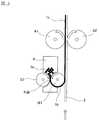
本発明に用いられるロールは、図1に示すロールM1とロールS1のごとく、一対の逆方向に回転するものである。
ロールM1及びロールS1上に複合粒子粉末1aを供給するためのフィーダー4が備えられていて、該フィーダー4から複合粒子粉末1aがロールM1,S1間に供給される。The roll used in the present invention rotates in a pair of opposite directions, like the roll M1 and the roll S1 shown in FIG.
The
ロールM1が反時計回りに、ロールS1が時計回りに回転する。
ロールM1の周速は、通常0.1〜100m/分、好ましくは1〜50m/分である。ロールS1の周速は、通常0.1〜100m/分、好ましくは1〜50m/分である。ロールM1とロールS1の間隔は、通常10〜500μm、好ましくは30〜300μmである。ロールM1のロール表面温度は、通常0〜200℃、好ましくは20〜150℃である。ロールS1のロール表面温度は、通常0〜200℃、好ましくは20〜150℃である。ロールM1とロールS1との間にかける圧力は、通常0.01〜10kN/cm、好ましくは0.02〜5kN/cmである。The roll M1 rotates counterclockwise and the roll S1 rotates clockwise.
The peripheral speed of the roll M1 is usually 0.1 to 100 m / min, preferably 1 to 50 m / min. The peripheral speed of the roll S1 is usually 0.1 to 100 m / min, preferably 1 to 50 m / min. The distance between the roll M1 and the roll S1 is usually 10 to 500 μm, preferably 30 to 300 μm. The roll surface temperature of the roll M1 is usually 0 to 200 ° C, preferably 20 to 150 ° C. The roll surface temperature of the roll S1 is usually 0 to 200 ° C, preferably 20 to 150 ° C. The pressure applied between the roll M1 and the roll S1 is usually 0.01 to 10 kN / cm, preferably 0.02 to 5 kN / cm.
ロールM1が反時計回りに、ロールS1が時計回りに回転することにより複合粒子粉末1aを咬み込み、複合粒子粉末1aを圧縮し、ロールM1に付着させる。
複合粒子粉末1aを圧縮して一方のロール面に付着させる方法は特に限定されないが、ロールM1及びロールS1の外周表面の性状が特に付着性に差をつける。例えば、マット処理、粗面化処理、メッキ処理、表面彫刻、離型処理、鏡面処理、艶消し処理などの表面処理を施すことで差がつく。例えば、ロールS1を鏡面処理し、ロールM1をマット処理することが好ましい。ロールM1及びロールS1の表面処理により、複合粒子粉末1aの咬み込み量を制御することもでき、後述するように、ロールA1,A2間を通した後に得られる電極層1cの厚さを変更することもできる。また、ロールM1,S1により圧縮することにより得られる圧粉層1bとの密着性の観点からロールM1の表面を連続的にサンドブラストによる粗面化処理をしてもよい。
また、ロールM1とロールS1とで付着性に差をつける方法として、前記方法以外に、ロールM1とロールS1とにおいて、電気伝導度、熱伝導率、放射率、熱吸収率などの異なる材質をそれぞれ用いることによっても差をつけることができる。
ここで、図2は、ロールM1及びロールS1の表面状態を示す概略図であり、ロールM1、ロールS1の表面をフィーダー4側から見た図である。そのため、図2においては、図面横方向がロールM1,S1の幅方向に相当し、図面縦方向がロールM1,S1の周方向に相当する。そして、ロールM1の表面処理は、図2に示すように幅方向の端部分を除いて表面処理を行うことが好ましい。また、この様な場合には、圧縮時において、表面処理を行っていない部分で圧縮される複合粒子粉末1aを、ロールM1またはロールS1から除去する装置を備えていてもよい。The roll M1 rotates counterclockwise and the roll S1 rotates clockwise to bite the
The method for compressing and adhering the
Further, as a method of making a difference in adhesion between the roll M1 and the roll S1, in addition to the above method, different materials such as electrical conductivity, thermal conductivity, emissivity, and heat absorption rate are used in the roll M1 and the roll S1. Differences can also be made by using each.
Here, FIG. 2 is a schematic view showing the surface states of the roll M1 and the roll S1, and is a view of the surfaces of the roll M1 and the roll S1 as seen from the
その他の複合粒子粉末1aを一方のロール面に付着させる方法としては、例えば、ロールM1及びロールS1の回転数に差をつける方法、ロールM1及びロールS1の径に差をつける方法などが挙げられる。 Examples of the method of attaching the other
ここで、ロールM1及びロールS1において、圧粉層1bの密度を複合粒子粉末1aの密度の100〜10000%となるように圧縮することが好ましく、200〜1000%となるように圧縮することがさらに好ましい。複合粒子粉末1aの密度とは、ゆるめかさ密度である。 Here, in roll M1 and roll S1, it is preferable to compress so that the density of the
ロールM1とロールS1との間で一旦圧縮された圧粉層1bは、圧縮力が解放されることによってロールM1上においてその厚さが復元する。圧粉層1bの、圧縮点であるP点およびその近傍における圧縮力印加時の厚さから、解放後の厚さへの復元率は、100%〜5000%であると好ましく、150〜1000%であるとより好ましい。ここで、圧粉層1bの復元率とは、圧縮力を解放した後の圧粉層1bの厚さを、圧縮点であるP点およびその近傍における圧縮力印加時の圧粉層の厚さで割り100を掛けた値である。圧縮点であるP点およびその近傍における圧粉層1bの厚さは、ロールM1,S1の間隔などから推算できる。
復元後の圧粉層1bの密度、即ち、ロールに付着している圧粉層1bの密度は、複合粒子粉末1aの密度の130%〜400%であると好ましく、150%〜300%であるとより好ましい。例えば、ゆるめかさ密度が0.45g/ccである複合粒子粉末1aをロールM1とロールS1により圧縮すると、圧粉層1bの密度は0.75g/ccとなる。The thickness of the green compact 1b once compressed between the roll M1 and the roll S1 is restored on the roll M1 when the compressive force is released. The restoration rate from the thickness at the time of compressive force application at the P point that is the compression point and the vicinity of the
The density of the compacted
ロールM1及びロールS1には、複合粒子粉末1aを供給するためのフィーダー4の手前部分にクリーニング機構を設けてロール表面に付着した複合粒子粉末1aを取り除いてもよい。また、ロールM1及びロールS1の圧縮部の下流側には、圧粉層1bの形成に寄与しなかった複合粒子粉末1aを回収する機構を設けても良い。 The roll M1 and the roll S1 may be provided with a cleaning mechanism in front of the
ロールM1に付着された圧粉層1cを長尺のシート状集電体2に転写させる。転写は、圧粉層1bとシート状集電体2を接触させて、ロールで加圧して圧着させる方法や、赤外線ヒーターや温風などで加温する方法、あるいは、冷風などで冷却する方法により行うことができる。な、ロールで加圧して圧着させる方法を用いる場合には、シート状集電体2を挟んで、ロールM1と反対側に、加圧用のバックアップロールを設けることが好ましい。 The
(加圧成形)
本発明の電気化学素子用電極の製造方法では、必要により、圧粉層1bと集電体2からなる積層体をさらに加圧成形する。圧粉層1bは、加圧され電極層1cとなる。
圧粉層1bは、ロールA1とロールA2との間で、加圧され、電極層1cとなる。
ロールA1は反時計回りに、ロールA2は時計回りに回転させる。ロールA1の周速は、通常0.1〜100m/分、好ましくは1〜50m/分である。ロールA2の周速は、通常0.1〜100m/分、好ましくは1〜50m/分である。ロールA1とロールA2の間隔は、通常60〜700μm、好ましくは100〜500μmである。ロールA1のロール表面温度は、通常0〜200℃、好ましくは20〜150℃である。ロールA2のロール表面温度は、通常0〜200℃、好ましくは20〜150℃である。ロールA1及びロールA2のロール径は圧粉層1bを圧縮する際に加える圧力に応じて決めることができるが、通常50〜1000mm、好ましくは100〜500mmである。ロールA1とロールA2との間にかける圧力は、通常0.01〜10kN/cm、好ましくは0.02〜5kN/cmである。ロールA1とロールA2との間にかける圧力は、ロールM1とロールS1との間にかける圧力より大きい。
ロールA1及びロールA2は、表面処理が施されていてもよい。例えば、ロールA1及びロールA2の外周面に凹凸等の彫刻を設けることにより電気化学素子用電極の表面に模様が形成され、表面の粗さを変更することもできる。(Pressure molding)
In the method for producing an electrode for an electrochemical element of the present invention, a laminate comprising the
The green
The roll A1 is rotated counterclockwise, and the roll A2 is rotated clockwise. The peripheral speed of the roll A1 is usually 0.1 to 100 m / min, preferably 1 to 50 m / min. The peripheral speed of the roll A2 is usually 0.1 to 100 m / min, preferably 1 to 50 m / min. The space | interval of roll A1 and roll A2 is 60-700 micrometers normally, Preferably it is 100-500 micrometers. The roll surface temperature of roll A1 is usually 0 to 200 ° C, preferably 20 to 150 ° C. The roll surface temperature of roll A2 is usually 0 to 200 ° C, preferably 20 to 150 ° C. Although the roll diameter of roll A1 and roll A2 can be determined according to the pressure added when compressing the
The roll A1 and the roll A2 may be subjected to surface treatment. For example, by providing engravings such as irregularities on the outer peripheral surfaces of the rolls A1 and A2, a pattern is formed on the surface of the electrode for an electrochemical element, and the roughness of the surface can be changed.
電極層1cは圧粉層1bよりも高い密度を有し、圧粉層1bは複合粒子粉末1aよりも高い密度を有する。
電極層1cの厚さは、通常10〜1000μm、より好ましくは20〜500μmである。The
The thickness of the
また、図3は、別の態様を示す図であり、図3に示す態様においては、上述したロールM1上に圧粉層1bを形成するための構成に加えて、集電体2を挟んで反対側に、上記と同様にして、同様の条件にて、ロールM2上に圧粉層1bを形成するための構成(すなわち、フィーダー4、および一対のロールM2,S2からなる構成)を備えている。そして、この図3に示す態様においては、ロールM1上およびロールM2上に、それぞれ形成された各圧粉層1bを、ロールM1とロールM2との間に集電体2を通すことで、集電体2の両面に、各圧粉層1bを加圧し、同時に転写させる。
あるいは、図4は、さらに別の態様を示す図であり、この図4に示す態様においては、図3に示す構成において、ロールA2と、ロールM2上に圧粉層1bを形成するための構成(すなわち、フィーダー4、および一対のロールM2、S2からなる構成)とを逆に配置している。そして、この図4に示す態様においては、ロールM1と、ロールA2との間に集電体2を通すことで、ロールM1上に形成された圧粉層1bを集電体2に転写させるとともに、加圧することで、電極層1cを集電体2の一方の面に形成する。次いで、ロールM2と、ロールA1との間に、一方の面に電極層1cが形成された集電体2を通すことで、ロールM2上に形成された圧粉層1bを集電体2の電極層1cが形成されていない面に転写させるとともに、加圧することで、電極層1cを集電体2の他方の面に形成する。Moreover, FIG. 3 is a figure which shows another aspect, and in the aspect shown in FIG. 3, in addition to the structure for forming the
Or FIG. 4 is a figure which shows another aspect, and in the aspect shown in this FIG. 4, in the structure shown in FIG. 3, the structure for forming the
1a・・・複合粒子粉末
1b・・・圧粉層
1c・・・電極層
2・・・集電体
M1、M2、S1、S2・・・ロール
A1、A2・・・加圧成形ロールDESCRIPTION OF
Claims (6)
Translated fromJapanesePriority Applications (1)
| Application Number | Priority Date | Filing Date | Title |
|---|---|---|---|
| JP2012201186AJP2013077560A (en) | 2011-09-14 | 2012-09-13 | Method for manufacturing electrode for electrochemical element |
Applications Claiming Priority (3)
| Application Number | Priority Date | Filing Date | Title |
|---|---|---|---|
| JP2011201154 | 2011-09-14 | ||
| JP2011201154 | 2011-09-14 | ||
| JP2012201186AJP2013077560A (en) | 2011-09-14 | 2012-09-13 | Method for manufacturing electrode for electrochemical element |
Publications (1)
| Publication Number | Publication Date |
|---|---|
| JP2013077560Atrue JP2013077560A (en) | 2013-04-25 |
Family
ID=48480855
Family Applications (1)
| Application Number | Title | Priority Date | Filing Date |
|---|---|---|---|
| JP2012201186APendingJP2013077560A (en) | 2011-09-14 | 2012-09-13 | Method for manufacturing electrode for electrochemical element |
Country Status (1)
| Country | Link |
|---|---|
| JP (1) | JP2013077560A (en) |
Cited By (46)
| Publication number | Priority date | Publication date | Assignee | Title |
|---|---|---|---|---|
| JP2015146246A (en)* | 2014-02-03 | 2015-08-13 | 日本ゼオン株式会社 | Method for producing electrode for lithium ion battery |
| JP2015146250A (en)* | 2014-02-03 | 2015-08-13 | トヨタ自動車株式会社 | Nonaqueous electrolyte secondary battery |
| JP2015170550A (en)* | 2014-03-10 | 2015-09-28 | トヨタ自動車株式会社 | Method for producing positive electrode for lithium secondary battery, positive electrode for lithium secondary battery and granulated product |
| JP2015201318A (en)* | 2014-04-07 | 2015-11-12 | トヨタ自動車株式会社 | Electrode sheet manufacturing method |
| JP2016081871A (en)* | 2014-10-22 | 2016-05-16 | トヨタ自動車株式会社 | Electrode manufacturing method and manufacturing apparatus |
| KR20160059966A (en)* | 2014-11-19 | 2016-05-27 | 도요타지도샤가부시키가이샤 | Method of manufacturing negative electrode for nonaqueous electrolyte secondary battery |
| JP2016103338A (en)* | 2014-11-27 | 2016-06-02 | トヨタ自動車株式会社 | Manufacturing method for cathode for lithium ion secondary battery |
| JP2016115578A (en)* | 2014-12-16 | 2016-06-23 | トヨタ自動車株式会社 | Electrode manufacturing method and electrode manufacturing device |
| JP2016152066A (en)* | 2015-02-16 | 2016-08-22 | トヨタ自動車株式会社 | Method for manufacturing nonaqueous electrolyte secondary battery |
| JP2016152169A (en)* | 2015-02-18 | 2016-08-22 | トヨタ自動車株式会社 | Method of manufacturing electrode |
| JP2016207340A (en)* | 2015-04-17 | 2016-12-08 | トヨタ自動車株式会社 | Electrode manufacturing equipment |
| DE102016111204A1 (en) | 2015-07-13 | 2017-01-19 | Toyota Jidosha Kabushiki Kaisha | Method for producing an electrode plate and electrode plate |
| JP2017022019A (en)* | 2015-07-13 | 2017-01-26 | トヨタ自動車株式会社 | Electrode sheet manufacturing method |
| JP2017091987A (en)* | 2015-11-17 | 2017-05-25 | トヨタ自動車株式会社 | Electrode manufacturing method |
| JP2017094552A (en)* | 2015-11-20 | 2017-06-01 | トヨタ自動車株式会社 | Film forming apparatus |
| KR20170086118A (en)* | 2015-01-05 | 2017-07-25 | 니폰 제온 가부시키가이샤 | Method for manufacturing electrode for lithium ion battery |
| US9917306B2 (en) | 2015-01-14 | 2018-03-13 | Toyota Jidosha Kabushiki Kaisha | Manufacturing method of electrode and wet granules |
| KR101842349B1 (en) | 2016-05-16 | 2018-03-26 | 동원시스템즈 주식회사 | Battery sheet coating device |
| US10022743B2 (en) | 2014-09-18 | 2018-07-17 | Panasonic Intellectual Property Management Co., Ltd. | Coating film production method, coating film production apparatus, coating film, nonaqueous secondary battery electrode plate, and mobile body |
| JP2019057431A (en)* | 2017-09-21 | 2019-04-11 | トヨタ自動車株式会社 | Method for producing negative electrode sheet |
| JP2019079723A (en)* | 2017-10-25 | 2019-05-23 | トヨタ自動車株式会社 | Method for manufacturing electrode sheet |
| US10396346B2 (en) | 2015-02-12 | 2019-08-27 | Toyota Jidosha Kabushiki Kaisha | Method of manufacturing negative electrode for nonaqueous electrolyte secondary battery |
| US10431807B2 (en) | 2014-09-12 | 2019-10-01 | Toyota Jidosha Kabushiki Kaisha | Method of manufacturing lithium-ion secondary battery electrode |
| US10673061B2 (en)* | 2017-07-31 | 2020-06-02 | Toyota Jidosha Kabushiki Kaisha | Electrode sheet manufacturing method |
| CN111293272A (en)* | 2018-12-06 | 2020-06-16 | 丰田自动车株式会社 | Electrode sheet manufacturing equipment |
| JP2020522090A (en)* | 2017-05-16 | 2020-07-27 | フラウンホーファー−ゲゼルシャフト ツゥア フェアデルング デア アンゲヴァンドテン フォァシュング エー.ファウ. | Dry film manufacturing method, rolling device, dry film, and substrate coated with dry film |
| JP2020116477A (en)* | 2019-01-18 | 2020-08-06 | 株式会社リコー | Coating applicator and liquid discharger |
| US11043658B2 (en) | 2018-11-26 | 2021-06-22 | Toyota Jidosha Kabushiki Kaisha | Electrode sheet manufacturing device |
| WO2021181887A1 (en) | 2020-03-11 | 2021-09-16 | パナソニックIpマネジメント株式会社 | Method for producing electrode and electrode mixture |
| WO2021181888A1 (en) | 2020-03-11 | 2021-09-16 | パナソニックIpマネジメント株式会社 | Electrode for secondary battery and method for producing the same |
| WO2021186864A1 (en) | 2020-03-19 | 2021-09-23 | パナソニックIpマネジメント株式会社 | Electrode for batteries, and battery |
| CN113619143A (en)* | 2021-10-14 | 2021-11-09 | 三一技术装备有限公司 | Dry-process electrode film preparation device and battery production line |
| EP4053932A1 (en) | 2021-03-01 | 2022-09-07 | Prime Planet Energy & Solutions, Inc. | Secondary battery electrode and method for producing the electrode |
| EP3982438A4 (en)* | 2019-08-19 | 2022-09-14 | FUJIFILM Corporation | Electrode moulded body production method |
| US11594712B2 (en) | 2021-02-22 | 2023-02-28 | Prime Planet Energy & Solutions, Inc. | Method for producing secondary battery electrodes |
| WO2023237507A1 (en) | 2022-06-08 | 2023-12-14 | Koenig & Bauer Ag | Machine for producing a product with a dry film applied to a carrier substrate |
| KR20240034019A (en)* | 2022-09-06 | 2024-03-13 | 엘지전자 주식회사 | Electronic device and method for controlling thereof |
| JP2024096522A (en)* | 2023-01-03 | 2024-07-16 | フオルクスワーゲン・アクチエンゲゼルシヤフト | Apparatus and method for manufacturing electrodes |
| EP4439692A1 (en)* | 2023-03-30 | 2024-10-02 | Volkswagen Aktiengesellschaft | Coating device, method and electrode |
| EP4439690A1 (en)* | 2023-03-30 | 2024-10-02 | Volkswagen Ag | Coating device, method and electrode |
| JP2024137852A (en)* | 2023-03-21 | 2024-10-07 | フォルクスヴァーゲン アクチエンゲゼルシャフト | Process Assembly and Method for Manufacturing Electrodes - Patent application |
| WO2025013735A1 (en)* | 2023-07-12 | 2025-01-16 | 山陽色素株式会社 | Carbon nanotube-containing powder for electrode of power storage device, electrode mixture paste, electrode for power storage device, and power storage device |
| US12288873B2 (en) | 2021-03-01 | 2025-04-29 | Prime Planet Energy & Solutions, Inc. | Secondary battery electrode and method for producing the electrode |
| WO2025100282A1 (en)* | 2023-11-08 | 2025-05-15 | パナソニックエナジー株式会社 | Powder rolling unit |
| US12327855B2 (en) | 2021-02-22 | 2025-06-10 | Prime Planet Energy & Solutions, Inc. | Method for producing secondary battery electrodes |
| US12444730B2 (en) | 2020-03-11 | 2025-10-14 | Panasonic Intellectual Property Management Co., Ltd. | Electrode for secondary battery and method for producing the same |
- 2012
- 2012-09-13JPJP2012201186Apatent/JP2013077560A/enactivePending
Cited By (69)
| Publication number | Priority date | Publication date | Assignee | Title |
|---|---|---|---|---|
| JP2015146246A (en)* | 2014-02-03 | 2015-08-13 | 日本ゼオン株式会社 | Method for producing electrode for lithium ion battery |
| JP2015146250A (en)* | 2014-02-03 | 2015-08-13 | トヨタ自動車株式会社 | Nonaqueous electrolyte secondary battery |
| JP2015170550A (en)* | 2014-03-10 | 2015-09-28 | トヨタ自動車株式会社 | Method for producing positive electrode for lithium secondary battery, positive electrode for lithium secondary battery and granulated product |
| JP2015201318A (en)* | 2014-04-07 | 2015-11-12 | トヨタ自動車株式会社 | Electrode sheet manufacturing method |
| US10431807B2 (en) | 2014-09-12 | 2019-10-01 | Toyota Jidosha Kabushiki Kaisha | Method of manufacturing lithium-ion secondary battery electrode |
| US10022743B2 (en) | 2014-09-18 | 2018-07-17 | Panasonic Intellectual Property Management Co., Ltd. | Coating film production method, coating film production apparatus, coating film, nonaqueous secondary battery electrode plate, and mobile body |
| JP2016081871A (en)* | 2014-10-22 | 2016-05-16 | トヨタ自動車株式会社 | Electrode manufacturing method and manufacturing apparatus |
| KR101700045B1 (en)* | 2014-11-19 | 2017-01-26 | 도요타지도샤가부시키가이샤 | Method of manufacturing negative electrode for nonaqueous electrolyte secondary battery |
| KR20160059966A (en)* | 2014-11-19 | 2016-05-27 | 도요타지도샤가부시키가이샤 | Method of manufacturing negative electrode for nonaqueous electrolyte secondary battery |
| US9960411B2 (en) | 2014-11-19 | 2018-05-01 | Toyota Jidosha Kabushiki Kaisha | Method of manufacturing negative electrode for nonaqueous electrolyte secondary battery |
| JP2016100117A (en)* | 2014-11-19 | 2016-05-30 | トヨタ自動車株式会社 | Method for producing negative electrode for non-aqueous electrolyte secondary battery |
| US10050256B2 (en) | 2014-11-27 | 2018-08-14 | Toyota Jidosha Kabushiki Kaisha | Method of manufacturing positive electrode for lithium ion secondary battery |
| JP2016103338A (en)* | 2014-11-27 | 2016-06-02 | トヨタ自動車株式会社 | Manufacturing method for cathode for lithium ion secondary battery |
| KR20160063991A (en)* | 2014-11-27 | 2016-06-07 | 도요타지도샤가부시키가이샤 | Method of manufacturing positive electrode for lithium ion secondary battery |
| KR101716587B1 (en)* | 2014-11-27 | 2017-03-14 | 도요타지도샤가부시키가이샤 | Method of manufacturing positive electrode for lithium ion secondary battery |
| JP2016115578A (en)* | 2014-12-16 | 2016-06-23 | トヨタ自動車株式会社 | Electrode manufacturing method and electrode manufacturing device |
| KR20170086118A (en)* | 2015-01-05 | 2017-07-25 | 니폰 제온 가부시키가이샤 | Method for manufacturing electrode for lithium ion battery |
| US9917306B2 (en) | 2015-01-14 | 2018-03-13 | Toyota Jidosha Kabushiki Kaisha | Manufacturing method of electrode and wet granules |
| US10396346B2 (en) | 2015-02-12 | 2019-08-27 | Toyota Jidosha Kabushiki Kaisha | Method of manufacturing negative electrode for nonaqueous electrolyte secondary battery |
| US10461310B2 (en) | 2015-02-16 | 2019-10-29 | Toyota Jidosha Kabushiki Kaisha | Manufacturing method for non-aqueous electrolyte secondary battery |
| JP2016152066A (en)* | 2015-02-16 | 2016-08-22 | トヨタ自動車株式会社 | Method for manufacturing nonaqueous electrolyte secondary battery |
| JP2016152169A (en)* | 2015-02-18 | 2016-08-22 | トヨタ自動車株式会社 | Method of manufacturing electrode |
| JP2016207340A (en)* | 2015-04-17 | 2016-12-08 | トヨタ自動車株式会社 | Electrode manufacturing equipment |
| US10263239B2 (en)* | 2015-07-13 | 2019-04-16 | Toyota Jidosha Kabushiki Kaisha | Method for manufacturing electrode sheet |
| KR20180029218A (en)* | 2015-07-13 | 2018-03-20 | 도요타지도샤가부시키가이샤 | Method for manufacturing electrode sheet |
| DE102016111204A1 (en) | 2015-07-13 | 2017-01-19 | Toyota Jidosha Kabushiki Kaisha | Method for producing an electrode plate and electrode plate |
| KR102194326B1 (en)* | 2015-07-13 | 2020-12-22 | 도요타지도샤가부시키가이샤 | Method for manufacturing electrode sheet |
| DE102016110481B4 (en) | 2015-07-13 | 2023-07-06 | Toyota Jidosha Kabushiki Kaisha | Method of manufacturing an electrode sheet |
| US10320002B2 (en) | 2015-07-13 | 2019-06-11 | Toyota Jidosha Kabushiki Kaisha | Method for manufacturing electrode sheet and electrode sheet |
| JP2017022019A (en)* | 2015-07-13 | 2017-01-26 | トヨタ自動車株式会社 | Electrode sheet manufacturing method |
| JP2017091987A (en)* | 2015-11-17 | 2017-05-25 | トヨタ自動車株式会社 | Electrode manufacturing method |
| JP2017094552A (en)* | 2015-11-20 | 2017-06-01 | トヨタ自動車株式会社 | Film forming apparatus |
| KR101842349B1 (en) | 2016-05-16 | 2018-03-26 | 동원시스템즈 주식회사 | Battery sheet coating device |
| JP7248835B2 (en) | 2017-05-16 | 2023-03-29 | フラウンホーファー-ゲゼルシャフト ツゥア フェアデルング デア アンゲヴァンドテン フォァシュング エー.ファウ. | Dry film manufacturing method, rolling apparatus, dry film, and substrate coated with dry film |
| US11990599B2 (en) | 2017-05-16 | 2024-05-21 | Fraunhofer-Gesellschaft Zur Foerderung Der Angewandten Forschung E.V. | Method for producing a dry film, rolling device |
| JP2020522090A (en)* | 2017-05-16 | 2020-07-27 | フラウンホーファー−ゲゼルシャフト ツゥア フェアデルング デア アンゲヴァンドテン フォァシュング エー.ファウ. | Dry film manufacturing method, rolling device, dry film, and substrate coated with dry film |
| JP2022062188A (en)* | 2017-05-16 | 2022-04-19 | フラウンホーファー-ゲゼルシャフト ツゥア フェアデルング デア アンゲヴァンドテン フォァシュング エー.ファウ. | Dry film manufacturing method, rolling mill, dry film, and substrate coated with dry film |
| US10673061B2 (en)* | 2017-07-31 | 2020-06-02 | Toyota Jidosha Kabushiki Kaisha | Electrode sheet manufacturing method |
| US10707476B2 (en) | 2017-09-21 | 2020-07-07 | Toyota Jidosha Kabushiki Kaisha | Method of producing a negative electrode sheet |
| JP2019057431A (en)* | 2017-09-21 | 2019-04-11 | トヨタ自動車株式会社 | Method for producing negative electrode sheet |
| JP2019079723A (en)* | 2017-10-25 | 2019-05-23 | トヨタ自動車株式会社 | Method for manufacturing electrode sheet |
| US11043658B2 (en) | 2018-11-26 | 2021-06-22 | Toyota Jidosha Kabushiki Kaisha | Electrode sheet manufacturing device |
| CN111293272B (en)* | 2018-12-06 | 2022-10-14 | 丰田自动车株式会社 | Electrode sheet manufacturing equipment |
| CN111293272A (en)* | 2018-12-06 | 2020-06-16 | 丰田自动车株式会社 | Electrode sheet manufacturing equipment |
| US11127986B2 (en) | 2018-12-06 | 2021-09-21 | Toyota Jidosha Kabushiki Kaisha | Electrode sheet manufacturing apparatus |
| JP7234646B2 (en) | 2019-01-18 | 2023-03-08 | 株式会社リコー | Applicator, device for ejecting liquid |
| JP2020116477A (en)* | 2019-01-18 | 2020-08-06 | 株式会社リコー | Coating applicator and liquid discharger |
| US11605805B2 (en) | 2019-08-19 | 2023-03-14 | Fujifilm Corporation | Method of manufacturing formed body for electrode |
| EP3982438A4 (en)* | 2019-08-19 | 2022-09-14 | FUJIFILM Corporation | Electrode moulded body production method |
| US12444730B2 (en) | 2020-03-11 | 2025-10-14 | Panasonic Intellectual Property Management Co., Ltd. | Electrode for secondary battery and method for producing the same |
| WO2021181888A1 (en) | 2020-03-11 | 2021-09-16 | パナソニックIpマネジメント株式会社 | Electrode for secondary battery and method for producing the same |
| WO2021181887A1 (en) | 2020-03-11 | 2021-09-16 | パナソニックIpマネジメント株式会社 | Method for producing electrode and electrode mixture |
| WO2021186864A1 (en) | 2020-03-19 | 2021-09-23 | パナソニックIpマネジメント株式会社 | Electrode for batteries, and battery |
| US11594712B2 (en) | 2021-02-22 | 2023-02-28 | Prime Planet Energy & Solutions, Inc. | Method for producing secondary battery electrodes |
| US12327855B2 (en) | 2021-02-22 | 2025-06-10 | Prime Planet Energy & Solutions, Inc. | Method for producing secondary battery electrodes |
| EP4053932A1 (en) | 2021-03-01 | 2022-09-07 | Prime Planet Energy & Solutions, Inc. | Secondary battery electrode and method for producing the electrode |
| US12283684B2 (en) | 2021-03-01 | 2025-04-22 | Prime Planet Energy & Solutions, Inc. | Secondary battery electrode and method for producing the electrode |
| US12288873B2 (en) | 2021-03-01 | 2025-04-29 | Prime Planet Energy & Solutions, Inc. | Secondary battery electrode and method for producing the electrode |
| CN113619143A (en)* | 2021-10-14 | 2021-11-09 | 三一技术装备有限公司 | Dry-process electrode film preparation device and battery production line |
| WO2023237507A1 (en) | 2022-06-08 | 2023-12-14 | Koenig & Bauer Ag | Machine for producing a product with a dry film applied to a carrier substrate |
| KR102705318B1 (en) | 2022-09-06 | 2024-09-11 | 엘지전자 주식회사 | Electronic device and method for controlling thereof |
| WO2024053757A1 (en)* | 2022-09-06 | 2024-03-14 | 엘지전자 주식회사 | Electronic device and electronic device control method |
| KR20240034019A (en)* | 2022-09-06 | 2024-03-13 | 엘지전자 주식회사 | Electronic device and method for controlling thereof |
| JP2024096522A (en)* | 2023-01-03 | 2024-07-16 | フオルクスワーゲン・アクチエンゲゼルシヤフト | Apparatus and method for manufacturing electrodes |
| JP2024137852A (en)* | 2023-03-21 | 2024-10-07 | フォルクスヴァーゲン アクチエンゲゼルシャフト | Process Assembly and Method for Manufacturing Electrodes - Patent application |
| EP4439690A1 (en)* | 2023-03-30 | 2024-10-02 | Volkswagen Ag | Coating device, method and electrode |
| EP4439692A1 (en)* | 2023-03-30 | 2024-10-02 | Volkswagen Aktiengesellschaft | Coating device, method and electrode |
| WO2025013735A1 (en)* | 2023-07-12 | 2025-01-16 | 山陽色素株式会社 | Carbon nanotube-containing powder for electrode of power storage device, electrode mixture paste, electrode for power storage device, and power storage device |
| WO2025100282A1 (en)* | 2023-11-08 | 2025-05-15 | パナソニックエナジー株式会社 | Powder rolling unit |
Similar Documents
| Publication | Publication Date | Title |
|---|---|---|
| JP2013077560A (en) | Method for manufacturing electrode for electrochemical element | |
| WO2013039131A1 (en) | Electrode for electrochemical element | |
| JP5423991B2 (en) | Lithium ion capacitor electrode and lithium ion capacitor | |
| JP6020452B2 (en) | Powder molding apparatus and method for manufacturing powder molded product | |
| JP6217741B2 (en) | Electrochemical element electrode composite particle, method for producing electrochemical element electrode composite particle, electrochemical element electrode and electrochemical element | |
| JP2013077559A (en) | Method for manufacturing electrode for electrochemical element | |
| JP6197789B2 (en) | Composite particles for electrochemical element electrodes, electrochemical element electrodes, and electrochemical elements | |
| JP5999237B2 (en) | Powder rolling apparatus and rolled sheet manufacturing method | |
| WO2011013756A1 (en) | Electrode for electrochemical-element, and electrochemical element | |
| JPWO2006115272A1 (en) | Composite particles for electrochemical device electrodes | |
| JP2010097830A (en) | Manufacturing method of electrode for electrochemical element | |
| JP2008098590A (en) | Electrode for electrochemical device and electrochemical device using the same | |
| JP2013045984A (en) | Electrode for power storage device, power storage device, and manufacturing method of electrode for power storage device | |
| JP2013077558A (en) | Electrode for electrochemical element | |
| JP2010109354A (en) | Method of manufacturing electrode for electrochemical element | |
| JP2010171366A (en) | Electrode composition layer with support and method of manufacturing electrode for electrochemical element | |
| JP6485359B2 (en) | Composite particles for electrochemical device electrodes | |
| WO2013118758A1 (en) | Apparatus for producing composite particles for electrochemical element electrodes and method for producing composite particles for electrochemical element electrodes | |
| JP2010171212A (en) | Electrode for electric double layer capacitor and method of manufacturing the same | |
| JP5311706B2 (en) | Method for producing composite particle for electrochemical device electrode | |
| JP2013077561A (en) | Method for manufacturing electrode for electrochemical element | |
| JP5790353B2 (en) | Powder rolling apparatus and rolled sheet manufacturing method | |
| JP5772429B2 (en) | Method for producing electrode layer | |
| JP2010171213A (en) | Electrode for electric double layer capacitor | |
| JP5845748B2 (en) | Powder rolling apparatus and rolled sheet manufacturing method |