JP2013060019A - Printing system and method - Google Patents
Printing system and methodDownload PDFInfo
- Publication number
- JP2013060019A JP2013060019AJP2012262140AJP2012262140AJP2013060019AJP 2013060019 AJP2013060019 AJP 2013060019AJP 2012262140 AJP2012262140 AJP 2012262140AJP 2012262140 AJP2012262140 AJP 2012262140AJP 2013060019 AJP2013060019 AJP 2013060019A
- Authority
- JP
- Japan
- Prior art keywords
- substrate
- ink
- printing system
- resolution
- Prior art date
- Legal status (The legal status is an assumption and is not a legal conclusion. Google has not performed a legal analysis and makes no representation as to the accuracy of the status listed.)
- Pending
Links
Images


Classifications
- G—PHYSICS
- G06—COMPUTING OR CALCULATING; COUNTING
- G06F—ELECTRIC DIGITAL DATA PROCESSING
- G06F3/00—Input arrangements for transferring data to be processed into a form capable of being handled by the computer; Output arrangements for transferring data from processing unit to output unit, e.g. interface arrangements
- G06F3/12—Digital output to print unit, e.g. line printer, chain printer
- B—PERFORMING OPERATIONS; TRANSPORTING
- B41—PRINTING; LINING MACHINES; TYPEWRITERS; STAMPS
- B41J—TYPEWRITERS; SELECTIVE PRINTING MECHANISMS, i.e. MECHANISMS PRINTING OTHERWISE THAN FROM A FORME; CORRECTION OF TYPOGRAPHICAL ERRORS
- B41J15/00—Devices or arrangements of selective printing mechanisms, e.g. ink-jet printers or thermal printers, specially adapted for supporting or handling copy material in continuous form, e.g. webs
- B41J15/005—Forming loops or sags in webs, e.g. for slackening a web or for compensating variations of the amount of conveyed web material (by arranging a "dancing roller" in a sag of the web material)
- B—PERFORMING OPERATIONS; TRANSPORTING
- B41—PRINTING; LINING MACHINES; TYPEWRITERS; STAMPS
- B41J—TYPEWRITERS; SELECTIVE PRINTING MECHANISMS, i.e. MECHANISMS PRINTING OTHERWISE THAN FROM A FORME; CORRECTION OF TYPOGRAPHICAL ERRORS
- B41J11/00—Devices or arrangements of selective printing mechanisms, e.g. ink-jet printers or thermal printers, for supporting or handling copy material in sheet or web form
- B41J11/0015—Devices or arrangements of selective printing mechanisms, e.g. ink-jet printers or thermal printers, for supporting or handling copy material in sheet or web form for treating before, during or after printing or for uniform coating or laminating the copy material before or after printing
- B41J11/002—Curing or drying the ink on the copy materials, e.g. by heating or irradiating
- B41J11/0021—Curing or drying the ink on the copy materials, e.g. by heating or irradiating using irradiation
- B41J11/00214—Curing or drying the ink on the copy materials, e.g. by heating or irradiating using irradiation using UV radiation
- B—PERFORMING OPERATIONS; TRANSPORTING
- B41—PRINTING; LINING MACHINES; TYPEWRITERS; STAMPS
- B41J—TYPEWRITERS; SELECTIVE PRINTING MECHANISMS, i.e. MECHANISMS PRINTING OTHERWISE THAN FROM A FORME; CORRECTION OF TYPOGRAPHICAL ERRORS
- B41J11/00—Devices or arrangements of selective printing mechanisms, e.g. ink-jet printers or thermal printers, for supporting or handling copy material in sheet or web form
- B41J11/66—Applications of cutting devices
- B—PERFORMING OPERATIONS; TRANSPORTING
- B41—PRINTING; LINING MACHINES; TYPEWRITERS; STAMPS
- B41J—TYPEWRITERS; SELECTIVE PRINTING MECHANISMS, i.e. MECHANISMS PRINTING OTHERWISE THAN FROM A FORME; CORRECTION OF TYPOGRAPHICAL ERRORS
- B41J13/00—Devices or arrangements of selective printing mechanisms, e.g. ink-jet printers or thermal printers, specially adapted for supporting or handling copy material in short lengths, e.g. sheets
- B41J13/10—Sheet holders, retainers, movable guides, or stationary guides
- B41J13/106—Sheet holders, retainers, movable guides, or stationary guides for the sheet output section
- B—PERFORMING OPERATIONS; TRANSPORTING
- B41—PRINTING; LINING MACHINES; TYPEWRITERS; STAMPS
- B41J—TYPEWRITERS; SELECTIVE PRINTING MECHANISMS, i.e. MECHANISMS PRINTING OTHERWISE THAN FROM A FORME; CORRECTION OF TYPOGRAPHICAL ERRORS
- B41J2/00—Typewriters or selective printing mechanisms characterised by the printing or marking process for which they are designed
- B41J2/005—Typewriters or selective printing mechanisms characterised by the printing or marking process for which they are designed characterised by bringing liquid or particles selectively into contact with a printing material
- B41J2/01—Ink jet
- B41J2/015—Ink jet characterised by the jet generation process
- B41J2/04—Ink jet characterised by the jet generation process generating single droplets or particles on demand
- B41J2/045—Ink jet characterised by the jet generation process generating single droplets or particles on demand by pressure, e.g. electromechanical transducers
- B41J2/04501—Control methods or devices therefor, e.g. driver circuits, control circuits
- B41J2/0458—Control methods or devices therefor, e.g. driver circuits, control circuits controlling heads based on heating elements forming bubbles
- B—PERFORMING OPERATIONS; TRANSPORTING
- B41—PRINTING; LINING MACHINES; TYPEWRITERS; STAMPS
- B41J—TYPEWRITERS; SELECTIVE PRINTING MECHANISMS, i.e. MECHANISMS PRINTING OTHERWISE THAN FROM A FORME; CORRECTION OF TYPOGRAPHICAL ERRORS
- B41J2/00—Typewriters or selective printing mechanisms characterised by the printing or marking process for which they are designed
- B41J2/005—Typewriters or selective printing mechanisms characterised by the printing or marking process for which they are designed characterised by bringing liquid or particles selectively into contact with a printing material
- B41J2/01—Ink jet
- B41J2/015—Ink jet characterised by the jet generation process
- B41J2/04—Ink jet characterised by the jet generation process generating single droplets or particles on demand
- B41J2/045—Ink jet characterised by the jet generation process generating single droplets or particles on demand by pressure, e.g. electromechanical transducers
- B41J2/04501—Control methods or devices therefor, e.g. driver circuits, control circuits
- B41J2/04581—Control methods or devices therefor, e.g. driver circuits, control circuits controlling heads based on piezoelectric elements
- B—PERFORMING OPERATIONS; TRANSPORTING
- B41—PRINTING; LINING MACHINES; TYPEWRITERS; STAMPS
- B41J—TYPEWRITERS; SELECTIVE PRINTING MECHANISMS, i.e. MECHANISMS PRINTING OTHERWISE THAN FROM A FORME; CORRECTION OF TYPOGRAPHICAL ERRORS
- B41J2/00—Typewriters or selective printing mechanisms characterised by the printing or marking process for which they are designed
- B41J2/005—Typewriters or selective printing mechanisms characterised by the printing or marking process for which they are designed characterised by bringing liquid or particles selectively into contact with a printing material
- B41J2/01—Ink jet
- B41J2/015—Ink jet characterised by the jet generation process
- B41J2/04—Ink jet characterised by the jet generation process generating single droplets or particles on demand
- B41J2/045—Ink jet characterised by the jet generation process generating single droplets or particles on demand by pressure, e.g. electromechanical transducers
- B41J2/04501—Control methods or devices therefor, e.g. driver circuits, control circuits
- B41J2/0459—Height of the driving signal being adjusted
- B—PERFORMING OPERATIONS; TRANSPORTING
- B41—PRINTING; LINING MACHINES; TYPEWRITERS; STAMPS
- B41J—TYPEWRITERS; SELECTIVE PRINTING MECHANISMS, i.e. MECHANISMS PRINTING OTHERWISE THAN FROM A FORME; CORRECTION OF TYPOGRAPHICAL ERRORS
- B41J2/00—Typewriters or selective printing mechanisms characterised by the printing or marking process for which they are designed
- B41J2/005—Typewriters or selective printing mechanisms characterised by the printing or marking process for which they are designed characterised by bringing liquid or particles selectively into contact with a printing material
- B41J2/01—Ink jet
- B41J2/015—Ink jet characterised by the jet generation process
- B41J2/04—Ink jet characterised by the jet generation process generating single droplets or particles on demand
- B41J2/045—Ink jet characterised by the jet generation process generating single droplets or particles on demand by pressure, e.g. electromechanical transducers
- B41J2/04501—Control methods or devices therefor, e.g. driver circuits, control circuits
- B41J2/04593—Dot-size modulation by changing the size of the drop
- B—PERFORMING OPERATIONS; TRANSPORTING
- B41—PRINTING; LINING MACHINES; TYPEWRITERS; STAMPS
- B41J—TYPEWRITERS; SELECTIVE PRINTING MECHANISMS, i.e. MECHANISMS PRINTING OTHERWISE THAN FROM A FORME; CORRECTION OF TYPOGRAPHICAL ERRORS
- B41J2/00—Typewriters or selective printing mechanisms characterised by the printing or marking process for which they are designed
- B41J2/005—Typewriters or selective printing mechanisms characterised by the printing or marking process for which they are designed characterised by bringing liquid or particles selectively into contact with a printing material
- B41J2/01—Ink jet
- B41J2/135—Nozzles
- B41J2/145—Arrangement thereof
- B41J2/155—Arrangement thereof for line printing
- B—PERFORMING OPERATIONS; TRANSPORTING
- B41—PRINTING; LINING MACHINES; TYPEWRITERS; STAMPS
- B41J—TYPEWRITERS; SELECTIVE PRINTING MECHANISMS, i.e. MECHANISMS PRINTING OTHERWISE THAN FROM A FORME; CORRECTION OF TYPOGRAPHICAL ERRORS
- B41J3/00—Typewriters or selective printing or marking mechanisms characterised by the purpose for which they are constructed
- B41J3/54—Typewriters or selective printing or marking mechanisms characterised by the purpose for which they are constructed with two or more sets of type or printing elements
- B41J3/543—Typewriters or selective printing or marking mechanisms characterised by the purpose for which they are constructed with two or more sets of type or printing elements with multiple inkjet print heads
- G—PHYSICS
- G06—COMPUTING OR CALCULATING; COUNTING
- G06F—ELECTRIC DIGITAL DATA PROCESSING
- G06F3/00—Input arrangements for transferring data to be processed into a form capable of being handled by the computer; Output arrangements for transferring data from processing unit to output unit, e.g. interface arrangements
- G06F3/12—Digital output to print unit, e.g. line printer, chain printer
- G06F3/1201—Dedicated interfaces to print systems
- G06F3/1202—Dedicated interfaces to print systems specifically adapted to achieve a particular effect
- G06F3/1203—Improving or facilitating administration, e.g. print management
- G06F3/1205—Improving or facilitating administration, e.g. print management resulting in increased flexibility in print job configuration, e.g. job settings, print requirements, job tickets
- G—PHYSICS
- G06—COMPUTING OR CALCULATING; COUNTING
- G06F—ELECTRIC DIGITAL DATA PROCESSING
- G06F3/00—Input arrangements for transferring data to be processed into a form capable of being handled by the computer; Output arrangements for transferring data from processing unit to output unit, e.g. interface arrangements
- G06F3/12—Digital output to print unit, e.g. line printer, chain printer
- G06F3/1201—Dedicated interfaces to print systems
- G06F3/1202—Dedicated interfaces to print systems specifically adapted to achieve a particular effect
- G06F3/1203—Improving or facilitating administration, e.g. print management
- G06F3/1207—Improving or facilitating administration, e.g. print management resulting in the user being informed about print result after a job submission
- G—PHYSICS
- G06—COMPUTING OR CALCULATING; COUNTING
- G06F—ELECTRIC DIGITAL DATA PROCESSING
- G06F3/00—Input arrangements for transferring data to be processed into a form capable of being handled by the computer; Output arrangements for transferring data from processing unit to output unit, e.g. interface arrangements
- G06F3/12—Digital output to print unit, e.g. line printer, chain printer
- G06F3/1201—Dedicated interfaces to print systems
- G06F3/1223—Dedicated interfaces to print systems specifically adapted to use a particular technique
- G06F3/1237—Print job management
- G06F3/1244—Job translation or job parsing, e.g. page banding
- G—PHYSICS
- G06—COMPUTING OR CALCULATING; COUNTING
- G06F—ELECTRIC DIGITAL DATA PROCESSING
- G06F3/00—Input arrangements for transferring data to be processed into a form capable of being handled by the computer; Output arrangements for transferring data from processing unit to output unit, e.g. interface arrangements
- G06F3/12—Digital output to print unit, e.g. line printer, chain printer
- G06F3/1201—Dedicated interfaces to print systems
- G06F3/1223—Dedicated interfaces to print systems specifically adapted to use a particular technique
- G06F3/1237—Print job management
- G06F3/1259—Print job monitoring, e.g. job status
- G—PHYSICS
- G06—COMPUTING OR CALCULATING; COUNTING
- G06F—ELECTRIC DIGITAL DATA PROCESSING
- G06F3/00—Input arrangements for transferring data to be processed into a form capable of being handled by the computer; Output arrangements for transferring data from processing unit to output unit, e.g. interface arrangements
- G06F3/12—Digital output to print unit, e.g. line printer, chain printer
- G06F3/1201—Dedicated interfaces to print systems
- G06F3/1278—Dedicated interfaces to print systems specifically adapted to adopt a particular infrastructure
- G06F3/1284—Local printer device
- B—PERFORMING OPERATIONS; TRANSPORTING
- B41—PRINTING; LINING MACHINES; TYPEWRITERS; STAMPS
- B41J—TYPEWRITERS; SELECTIVE PRINTING MECHANISMS, i.e. MECHANISMS PRINTING OTHERWISE THAN FROM A FORME; CORRECTION OF TYPOGRAPHICAL ERRORS
- B41J2202/00—Embodiments of or processes related to ink-jet or thermal heads
- B41J2202/01—Embodiments of or processes related to ink-jet heads
- B41J2202/20—Modules
Landscapes
- Engineering & Computer Science (AREA)
- Theoretical Computer Science (AREA)
- Human Computer Interaction (AREA)
- Physics & Mathematics (AREA)
- General Engineering & Computer Science (AREA)
- General Physics & Mathematics (AREA)
- Health & Medical Sciences (AREA)
- General Health & Medical Sciences (AREA)
- Toxicology (AREA)
- Ink Jet (AREA)
- Accessory Devices And Overall Control Thereof (AREA)
- Record Information Processing For Printing (AREA)
- Particle Formation And Scattering Control In Inkjet Printers (AREA)
Abstract
Description
Translated fromJapanese本発明は、プリントシステムおよびプリント方法に関する。 The present invention relates to a printing system and a printing method.
本願は、米国法典第35編第119条(e)の下で、引用によりその全ての内容をここに包含する、2004年9月7日に出願された「プリントシステムおよびプリント方法における可変解像度」と題する米国仮特許出願第60/607753号の優先権を主張するものである。 This application is entitled “Variable Resolution in Printing System and Printing Method” filed on Sep. 7, 2004, which is hereby incorporated by reference under US 35 USC 119 (e). Claims the priority of US Provisional Patent Application No. 60 / 607,753 entitled
単一パスプリントシステム等のプリントシステムを用いて、その動作寿命の過程において、様々な異なる基体上に様々な異なるインクがプリントされ得る。一般的に、単一パスプリントシステムは、画像の性質(例えば、グラフィックと文字との割合)、基体の組成、および用いられるインクのタイプに関わりなく、プロセス方向において単一解像度で(即ち、固有解像度で)プリントするよう構成される。従って、一部の用途では、解像度が最適な解像度よりも低いことがあり、基体に付着したインクが不十分なことに起因する画像エラーが生じ得る。或いは、別の用途では、システムの固有解像度が、そのプリントジョブに対する最適な解像度より高いことがあり、基体に付着したインクが多過ぎることに起因する画像エラーが生じ得る。例えば、照射によって硬化するまでは液体の状態に保たれるUV硬化インク等といった一部のインクでは、様々なタイプの用紙を用いた場合に線幅のばらつきとして現れる画質のばらつきが生じ得る。様々な基体へのプリントを行う際に伴い得る画質のばらつきを軽減するための1つの手法は、例えば、異なる用紙タイプと関係する異なる線の広がり特性を補償するために、液滴質量を調節することである。 Using a printing system, such as a single pass printing system, a variety of different inks can be printed on a variety of different substrates in the course of its operational life. In general, single pass printing systems have a single resolution (ie, unique) in the process direction regardless of the nature of the image (eg, graphic to character ratio), the composition of the substrate, and the type of ink used. Configured to print (in resolution). Thus, in some applications, the resolution may be lower than the optimal resolution, and image errors may result from insufficient ink adhering to the substrate. Alternatively, in other applications, the inherent resolution of the system may be higher than the optimal resolution for that print job, resulting in image errors due to too much ink deposited on the substrate. For example, some inks, such as UV curable inks that remain in a liquid state until cured by irradiation, can cause image quality variations that appear as line width variations when using various types of paper. One approach to reducing image quality variations that can be associated with printing on various substrates is to adjust drop mass, for example, to compensate for the different line spread characteristics associated with different paper types. That is.
本発明は、可変レイダウンを用いてプリントシステムを操作する方法、それに関連するプリント方法、プリントシステム、およびコントローラを提供することを課題とする。 It is an object of the present invention to provide a method for operating a printing system using variable laydown, a printing method related to the method, a printing system, and a controller.
概括的に、本発明は第1の態様において、可変レイダウンを用いてプリントシステムを操作する方法であって、システムにプリントジョブ情報を供給する工程と、プリントジョブ情報に基づいてインクレイダウンを選択する工程と、このインクレイダウンに基づいてプリントシステムに対する発射指示を生成する工程と、このインクレイダウンにて基体に画像をプリントする工程と、を備えるプリントシステム操作方法であることを特徴とする。 In general, in a first aspect, the present invention is a method for operating a printing system using variable laydown, the step of supplying print job information to the system, and selecting ink laydown based on the print job information. A printing system operating method comprising: a step, a step of generating a firing instruction for the print system based on the ink laydown, and a step of printing an image on a substrate by the ink laydown.
この方法の複数の実施形態は、以下の構成要件および/または他の態様の構成要件の1つ以上を含み得る。インクレイダウンを選択する工程は、プリントジョブ情報に基づいてプリント解像度を選択することおよび/またはプリントジョブ情報に基づいて液滴質量を選択することを含み得る。プリントシステムと通信するクライアントは、該システムにプリントジョブ情報を供給し得る。クライアントは、発射指示を生成し得る。プリントシステムは、プリントジョブ情報から発射指示を生成し得る。発射指示は、プリントジョブ情報にラスタ画像処理を行うことによって生成され得る。発射指示は、選択されたプリント解像度に基づいて生成され得る。発射指示を生成する工程は、複数の解像度に対応する複数のセットの発射指示を生成することを含み得る。発射指示を生成する工程は、複数のセットの発射指示のうち、選択されたプリント解像度に対応する1セットの発射指示を選択することを更に含み得る。 Embodiments of the method may include one or more of the following configuration requirements and / or configuration features of other aspects. Selecting the inlaydown may include selecting a print resolution based on the print job information and / or selecting a drop mass based on the print job information. A client communicating with the printing system may provide print job information to the system. The client may generate a firing instruction. The printing system may generate a firing instruction from the print job information. The firing instruction can be generated by performing raster image processing on the print job information. A firing instruction may be generated based on the selected print resolution. Generating the firing instructions may include generating multiple sets of firing instructions corresponding to multiple resolutions. The step of generating the firing instruction may further include selecting a set of firing instructions corresponding to the selected print resolution from the plurality of sets of firing instructions.
インクレイダウンを選択する工程が、プリントジョブ情報に基づいてプリント解像度を選択することを含む実施形態では、選択されたプリント解像度は約100dpi〜2000dpiであり得る。選択されたプリント解像度は、移動方向と直交する方向のプリント解像度とは異なり得る。プリント解像度は、基体上に所定のプリント線幅を設けるよう選択され得る。 In embodiments where selecting the inlaydown includes selecting a print resolution based on the print job information, the selected print resolution can be between about 100 dpi and 2000 dpi. The selected print resolution may be different from the print resolution in the direction orthogonal to the moving direction. The print resolution can be selected to provide a predetermined print line width on the substrate.
インクレイダウンは、基体の組成および/または画像のプリントに用いられるインクの組成に基づいて選択され得る。インクレイダウンは、画像の構成に基づいて選択され得る。インクレイダウンは、ルックアップテーブルに従って選択され得る。画像は、固有解像度を有するエンコーダからの基体追跡信号に従ってプリントされ得る。固有解像度はプリント解像度とは異なり得る。 Inlaydown may be selected based on the composition of the substrate and / or the composition of the ink used to print the image. The inlaydown can be selected based on the composition of the image. The inlaydown may be selected according to a lookup table. The image can be printed according to a substrate tracking signal from an encoder having an inherent resolution. The inherent resolution can be different from the print resolution.
概括的に、本発明は別の態様において、基体とプリントヘッドとの相対移動を生じさせる工程と、固有解像度を有するエンコーダを用いて、基体とプリントヘッドとの相対的な位置に基づく基体追跡信号を生成する工程と、基体の組成に基づきインクレイダウンを選択する工程と、基体追跡信号およびインクレイダウンに基づき画素トリガ信号を生成する工程と、プリントヘッドを用いてこのインクレイダウンにて基体上へのプリントを行う工程とを備える方法であることを特徴とする。 In general, in another aspect, the present invention provides a substrate tracking signal based on the relative position of the substrate and the printhead using an encoder having a native resolution and a relative movement between the substrate and the printhead. Generating an ink laydown based on the composition of the substrate, generating a pixel trigger signal based on the substrate tracking signal and the ink laydown, and applying the ink laydown on the substrate using the printhead. And a step of performing printing.
この方法の複数の実施形態は、以下の構成要件および/または他の態様の構成要件の1つ以上を含み得る。インクレイダウンは、固有解像度とは異なるプリント解像度に対応し得る。画素トリガ信号は、位相ロックループを用いて生成され得る。 Embodiments of the method may include one or more of the following configuration requirements and / or configuration features of other aspects. Inlaydown may correspond to a print resolution that is different from the native resolution. The pixel trigger signal can be generated using a phase locked loop.
概括的に、本発明は更に別の態様において、クライアントから受け取ったプリントジョブを実行するプリントシステムであることを特徴とする。このシステムは、プリントヘッドを有するプリントステーションと、プリントステーションと基体との相対移動を生じさせる基体移送装置と、プリントステーションおよびクライアントと通信するシステムコントローラとを備え、動作中に、システムコントローラが、クライアントから受け取ったプリントジョブに基づいてインクレイダウンを選択し、このインクレイダウンに基づいて発射指示を生成し、プリントヘッドに、このインクレイダウンにて基体上に画像をプリントさせる。 In general, in yet another aspect, the invention features a print system that executes a print job received from a client. The system includes a print station having a print head, a substrate transfer device that causes relative movement between the print station and the substrate, and a system controller in communication with the print station and the client. An ink laydown is selected based on the print job received from the printer, a firing instruction is generated based on the ink laydown, and the print head prints an image on the substrate using the ink laydown.
本システムの複数の実施形態は、以下の構成要件および/または他の態様の構成要件の1つ以上を含み得る。システムコントローラは、基体とプリントヘッドとの相対的な位置に基づいて基体追跡信号を生成するよう構成され固有解像度を有するエンコーダを更に備え得る。システムコントローラは、プリントヘッドに、固有解像度とは異なる移動方向のプリント解像度にて基体上へのプリントを行わせるよう構成され得る。システムコントローラは、クライアントから受け取ったプリントジョブ情報に従ってプリントヘッドに駆動パルスを供給するよう構成された駆動パルスコントローラを更に備え得る。駆動パルスコントローラは、基体追跡信号に基づいて駆動パルスを変調し得る。駆動パルスコントローラは、基体追跡信号周波数とは異なる周波数を有する画素トリガ信号を用いて駆動パルスを変調し得る。駆動パルスコントローラは、基体追跡信号に基づいて画素トリガ信号を生成する位相ロックループを備え得る。システムコントローラは、プリントジョブ情報に基づいて駆動パルスコントローラに対する発射指示を生成するラスタ画像処理プロセッサを備え得る。システムコントローラは、駆動パルスコントローラに対する発射指示を格納するメモリバッファを備え得る。メモリバッファは、複数のプリント解像度に対応する発射指示を格納するのに十分なメモリを有し得る。複数の解像度は約100dpi〜2000dpiであり得る。 Embodiments of the system may include one or more of the following configuration requirements and / or configuration features of other aspects. The system controller may further comprise an encoder configured to generate a substrate tracking signal based on the relative position of the substrate and the printhead and having a native resolution. The system controller may be configured to cause the print head to print on the substrate at a print resolution in a direction of movement different from the native resolution. The system controller may further comprise a drive pulse controller configured to supply drive pulses to the print head in accordance with print job information received from the client. The drive pulse controller may modulate the drive pulse based on the substrate tracking signal. The drive pulse controller may modulate the drive pulse with a pixel trigger signal having a frequency different from the substrate tracking signal frequency. The drive pulse controller may comprise a phase locked loop that generates a pixel trigger signal based on the substrate tracking signal. The system controller may comprise a raster image processor that generates firing instructions for the drive pulse controller based on the print job information. The system controller may comprise a memory buffer that stores firing instructions for the drive pulse controller. The memory buffer may have sufficient memory to store firing instructions corresponding to multiple print resolutions. The multiple resolutions can be about 100 dpi to 2000 dpi.
概括的に、本発明は別の実施形態において、プリントヘッドに基体上へのプリントを行わせるよう構成されたコントローラであって、メモリバッファを有するコントローラであることを特徴とする。 In general, in another embodiment, the invention features a controller configured to cause a printhead to print on a substrate, the controller having a memory buffer.
このコントローラは、上記システムに含まれ得るものであり、且つ/または、上記方法の一方または両方を実施するために用いられ得る。 This controller can be included in the system and / or can be used to perform one or both of the methods.
本発明の複数の実施形態は、以下の長所の1つ以上を有し得る。複数の実施形態は、1つのプリント装置に対して、広い範囲のインクレイダウンを提供し得る。従って、複数の実施形態は、プリント品質を落とすことなく、様々なタイプの基体およびインクを単一のプリント装置で用いることを可能にし得る。プリントされる画像の構成に基づいてレイダウンを調節し、異なる画像構成に対して一貫した画質を提供することができる。ベタを含む画像については、所望に応じて基体に連続した被覆が設けられるように、レイダウンを調節できる。透けおよび/または反転文字の埋まりを低減(即ち、解消)するように、レイダウンを調節できる。ハードウェアを変更せずとも、ソフトウェアに変更を行うことにより、レイダウンを変えることができる。液滴質量を調節せずとも、レイダウンを変えることができる。広い範囲のインクレイダウンにより、他のプリントエラー原因に対するプリント装置の許容度を高めることができる。様々な組み合わせのインクおよび基体に対して、ノミナル線幅を維持することができる。 Embodiments of the invention may have one or more of the following advantages. Embodiments can provide a wide range of ink laydowns for a single printing device. Thus, embodiments may allow different types of substrates and inks to be used in a single printing device without sacrificing print quality. The laydown can be adjusted based on the composition of the printed image to provide a consistent image quality for different image configurations. For solid images, the laydown can be adjusted so that a continuous coating is provided on the substrate as desired. The laydown can be adjusted to reduce (i.e., eliminate) show-through and / or fill of inverted characters. You can change the laydown by making changes to the software without changing the hardware. The laydown can be changed without adjusting the drop mass. A wide range of ink laydowns can increase the tolerance of the printing device for other causes of print errors. The nominal line width can be maintained for various combinations of inks and substrates.
添付の図面および以下の記載において、本発明の1つ以上の実施形態を詳細に説明する。これらの説明および図面から、本発明の他の特徴および長所が明らかになる。 The details of one or more embodiments of the invention are set forth in the accompanying drawings and the description below. From these descriptions and drawings, other features and advantages of the present invention will become apparent.
図面中、同一参照番号は同一要素を表す。 In the drawings, the same reference number represents the same element.
或る態様において、本発明は、プリントシステムを用いる様々なプリントジョブに対して、可変インクレイダウン(ink laydown)でプリントを行うことを特徴とする。これにより、システムで様々な組み合わせの基体およびインクを用いた場合に生じ得る、最適でないインクレイダウンと関係するプリントエラーを低減できる。 In one aspect, the invention features printing with variable ink laydown for various print jobs using the printing system. This can reduce print errors associated with sub-optimal ink laydown that can occur when using various combinations of substrates and inks in the system.
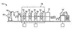
図1を参照すると、連続ウェブプリントシステム10は、移動するウェブ14上に複数の異なる色をプリントするための一続きのステーションまたはプリントタワー12を含む。ウェブ14は、スタンド16上の供給ロール15から、プリントステーション12へと導く用紙経路へと駆動される。4つのプリントステーションがプリントゾーン18を定め、そこで基体にインクが適用される。最後のプリントステーションの後に、光学硬化ステーション17(例えば、オーブンまたはUV源)が配置され得る。プリント後、ウェブは各シートに裁断され、それらはステーション19でスタックされる。新聞紙面等といった、幅広のフォーマットのウェブをプリントするために、プリントステーションは、一般的に、約25〜30インチ(約63〜76センチメートル)以上のウェブ幅に対応する。インクジェット印刷用に適合可能なオフセット平版印刷用の一般的なレイアウトは、その全内容を参照して本願明細書に組み込む米国特許第5,365,843号明細書で更に説明されている。 With reference to FIG. 1, a continuous
更に図2を参照すると、各プリントステーションはプリントバー24を含む。プリントバー24は、ウェブ14上に所望の画像を描画するためにインクを射出するアレイ状に配列された複数のプリントヘッド30を取り付けるための構造である。プリントヘッド30は、プリントヘッドのインク射出面(図2には図示せず)がプリントバー24の下面から露出するようにして、プリントバーの受容部21に取り付けられる。プリントヘッド30を、複数のノズル開口がオフセットされるようアレイ状に配列することで、プリント解像度またはプリント速度を高めることができる。 Still referring to FIG. 2, each print station includes a
プリントヘッド30は、微細に離間された複数の小さいノズル開口部(オリフィスとも呼ばれる)のアレイを有するドロップ・オン・デマンド型インクジェットプリントヘッド等といった様々なタイプであり得る。各オリフィスを個別に制御して、インクを画像の所望の位置、即ち画素に、選択的に射出することができる。例えば、1つのインクジェットヘッドは、少なくとも100画素(ドット)・パー・インチ(dpi)、場合によってはそれを遥かに上回るプリント解像度に対応して離間された、256個のオリフィスを有し得る。この複数のオリフィスの密なアレイにより、複雑で非常に精密な画像を生成することがきる。高性能プリントヘッドでは、ノズル開口の直径は一般的に50ミクロン以下(例えば、25ミクロン前後)であり、ノズル開口は25〜300ノズル/インチのピッチで離間され、100〜3000dpi以上の解像度を有し、約2〜50ピコリットル以下の液滴サイズを提供する。液滴の射出周波数は一般的に10kHz以上である。ドロップ・オン・デマンド型圧電プリントヘッドの例は、フィッシュベックら(Fishbeck et al.)の米国特許第4,825,227号、ホイシントン(Hoisington)の米国特許第5,265,315号、ハイン(Hine)の米国特許第4,937,598号、ビブルら(Bibl et al.)の米国特許出願公開第2004−0004649号、およびチェンら(Chen et al.)の米国特許仮出願第60/510,459号の各明細書に記載されており、これら全ての全内容を参照して本願明細書に組み込む。例えば、インクの加熱によって射出を行うサーマルインクジェット・プリントヘッド等といった他のタイプのプリントヘッドを用いることもできる。インク液滴の連続流を偏向することによる連続型インクジェットヘッドを用いることもできる。一般的な構成では、ウェブ経路とプリントバーとの離間距離は約0.1〜1ミリメートルである。 The
インクレイダウンとは、基体の単位面積当たりのインクの体積(または質量でも同等である)のことである。プリント解像度および/または液滴質量を変えることにより、インクレイダウンを変えることができる。ウェブ横断方向のプリント解像度は、基体上において隣接するプリントラインをプリントするノズルの間隔によって決定される(即ち、機能上隣接するノズル)。機能上隣接するノズルは、同じまたは異なるプリントヘッドに存在し得る。一般的なウェブ横断方向の解像度は、約100dpi〜1000dpi(例えば、約300dpi以上、400dpi以上、500dpi以上、600dpi以上、700dpi以上、800dpi以上)であり得る。プロセス方向の解像度は、ジェット射出周波数およびウェブ速度によって異なる。多くの実施形態では、ジェット射出周波数は、エンコーダによってウェブ速度に固定される(これについては後述する)。プロセス方向解像度は、各プリントジョブ毎に同じであってもよく、または、異なるプリントジョブ毎に異なっていてもよい。一般的に、プロセス方向解像度は、約100dpi〜2000dpi(例えば、約300dpi〜1000dpiであり、約600dpi等)である。異なるプロセス方向解像度を実現する方法については後述する。 Increedown is the volume (or mass) of ink per unit area of the substrate. By changing the print resolution and / or drop mass, the ink laydown can be changed. The print resolution in the cross-web direction is determined by the spacing of nozzles that print adjacent print lines on the substrate (ie, functionally adjacent nozzles). Functionally adjacent nozzles can be on the same or different printheads. Typical cross-web resolution can be about 100 dpi to 1000 dpi (eg, about 300 dpi or more, 400 dpi or more, 500 dpi or more, 600 dpi or more, 700 dpi or more, 800 dpi or more). Process direction resolution depends on jet injection frequency and web speed. In many embodiments, the jet injection frequency is fixed at the web speed by an encoder (this is described below). The process direction resolution may be the same for each print job, or may be different for different print jobs. Generally, the process direction resolution is about 100 dpi to 2000 dpi (eg, about 300 dpi to 1000 dpi, such as about 600 dpi). A method for realizing different process direction resolutions will be described later.
プリントヘッドの駆動波形(例えば、駆動波形の振幅および/または形状)を変更することにより、および/または、1つの画素位置に複数の液滴を射出することにより、液滴質量を変えることができる。例えば、一般的には、パルスの振幅が大きいほど、射出される液滴の質量が大きくなる。幾つかの実施形態では、所望のレイダウンに応じて液滴質量を約5%以上(例えば、約10%以上、約15%以上、約20%以上)変えることができる。 The droplet mass can be changed by changing the drive waveform of the print head (eg, the amplitude and / or shape of the drive waveform) and / or by ejecting multiple droplets at one pixel location. . For example, in general, the larger the pulse amplitude, the larger the mass of the ejected droplet. In some embodiments, the drop mass can be varied by about 5% or more (eg, about 10% or more, about 15% or more, about 20% or more) depending on the desired laydown.
幾つかの実施形態では、インクレイダウンを変えるために、液滴質量とプロセス方向解像度との両方を変える。プロセス方向解像度を変えることにより、大規模なレイダウン調節(例えば、約100%以上、約200%以上、約300%以上、約500%以上)を行うことができ、液滴質量を変えることにより、細かい規模のレイダウン調節(例えば、約50%以下、約25%以下、約10%以下、約5%以下)を行うことができる。 In some embodiments, both drop mass and process direction resolution are changed to change the ink laydown. By changing the process direction resolution, large-scale laydown adjustments (eg, about 100% or more, about 200% or more, about 300% or more, about 500% or more) can be performed, and by changing the droplet mass, Fine scale laydown adjustments (eg, about 50% or less, about 25% or less, about 10% or less, about 5% or less) can be made.
図3を参照すると、システムコントローラ300は、プリントシステム100の動作を制御する。システムコントローラ300はクライアント310と通信し、クライアント310は、コントローラにプリントジョブ情報を提供する。一般的に、クライアントは、プリントジョブのコンパイルに用いられる、例えば、デスクトップパブリッシング機能を有するリモートコンピュータである。システムコントローラは、プリントヘッド301に対する発射指示を生成するラスタ画像処理(RIP)プロセッサ320を含む。システムコントローラは、駆動パルスコントローラ311(ヘッドデータ経路およびヘッド駆動回路を含む)を介して、プリントヘッド301に発射指示を送る。駆動パルスコントローラ311は、画素トリガ信号を用いて、プリントヘッド301に発射指示を送る。システムコントローラ300は、エンコーダ330も含む。エンコーダ330は、プリントヘッド301に対するウェブの位置を追跡し、駆動パルスコントローラ311に基体追跡信号を供給する。駆動パルスコントローラ311は、基体追跡信号に基づいて画素トリガ信号を生成する。エンコーダ330は、プリントシステムを通るウェブの相対移動を制御するウェブコントローラ340と通信する。ウェブコントローラ340およびRIPプロセッサ320は、ユーザインターフェイス350と通信する。オペレータは、ユーザインターフェイス350から、システムコントローラ300に対する指示を入力できる。 Referring to FIG. 3, the system controller 300 controls the operation of the printing system 100. The system controller 300 communicates with the
上述したように、プロセス方向解像度は、ジェット射出周波数およびウェブ速度に関係し、これらは共に、システムコントローラによって制御される。具体的には、プロセス方向解像度は、ウェブ速度に対するジェット射出周波数の比率に比例する。上述したように、エンコーダは、プリントヘッドに対するウェブの位置を追跡して、基体追跡信号を生成する。システムコントローラは基体追跡信号を用いて、プリントヘッドに送られる発射指示をゲート制御する。エンコーダは、基体追跡信号パルス間のウェブ変位に対応する固有解像度を有する。例えば、光源と検出器との間でビームを遮断するよう構成された複数の放射状のスリットを有するウェブ駆動軸を有する光エンコーダが、ビームが遮断される度に基体追跡信号パルスを生成する。従って、各パルスは、ウェブの変位(これは軸の半径に依存する)に対応する。システムが、基体追跡信号パルスを用いて発射指示をゲート制御する場合には、ウェブ方向解像度はこの変位に対応する。 As mentioned above, process direction resolution is related to jet injection frequency and web speed, both of which are controlled by the system controller. Specifically, process direction resolution is proportional to the ratio of jet injection frequency to web speed. As described above, the encoder tracks the position of the web relative to the print head and generates a substrate tracking signal. The system controller uses the substrate tracking signal to gate firing instructions sent to the print head. The encoder has an inherent resolution corresponding to the web displacement between the substrate tracking signal pulses. For example, an optical encoder having a web drive axis with a plurality of radial slits configured to block the beam between the light source and the detector generates a substrate tracking signal pulse each time the beam is blocked. Thus, each pulse corresponds to a web displacement (which depends on the radius of the axis). If the system uses a substrate tracking signal pulse to gate the firing indication, the web orientation resolution corresponds to this displacement.
プロセス方向解像度は固有解像度に固定されない。この解像度は、プリントジョブに応じて変化し得る。固有解像度とは異なる解像度に対応するために、システムコントローラは、基体追跡信号および選択された解像度に基づいて画素トリガ信号を生成する。次に、画素トリガ信号を用いて発射指示をゲート制御することにより、プリント画素の横列間に適切な遅延を設けることで、選択された解像度でのプリントを行う。 The process direction resolution is not fixed to the intrinsic resolution. This resolution can vary depending on the print job. To accommodate a resolution that is different from the native resolution, the system controller generates a pixel trigger signal based on the substrate tracking signal and the selected resolution. Next, the firing instruction is gated using the pixel trigger signal to provide an appropriate delay between the rows of print pixels, thereby printing at the selected resolution.
幾つかの実施形態では、位相ロックループを用いて、基体追跡信号から画素トリガ信号を生成できる。位相ロックループは、基体追跡信号の周波数を増減して、選択された解像度に対応する周波数を有する画素トリガ信号を供給する。 In some embodiments, a pixel lock signal can be generated from the substrate tracking signal using a phase locked loop. The phase lock loop increases or decreases the frequency of the substrate tracking signal to provide a pixel trigger signal having a frequency corresponding to the selected resolution.
幾つかの実施形態では、固有解像度は、選択された解像度の範囲より大きい(例えば、5〜20倍大きい)ことがあり得る。例えば、選択された解像度が一般的に約100〜1000dpiである場合に、固有解像度は約5000、10000、20000dpi以上に対応し得る。 In some embodiments, the intrinsic resolution can be greater (eg, 5 to 20 times greater) than the selected resolution range. For example, if the selected resolution is typically about 100-1000 dpi, the native resolution may correspond to about 5000, 10000, 20000 dpi or more.
或いは、基体追跡信号とは異なる画素トリガ信号を生成する代わりに、幾つかの実施形態では、複数のエンコーダ(各エンコーダは異なる固有解像度を有する)を用いることができる。例えば、1つのシステムが、3つ(以上)の固有解像度を提供する3つ(以上)の異なるエンコーダを含むことができる。システムコントローラは、発射指示をゲート制御するために、選択された解像度に対応する基体追跡信号を選択して用いることができる。 Alternatively, instead of generating a different pixel trigger signal than the substrate tracking signal, in some embodiments, multiple encoders (each encoder having a different native resolution) can be used. For example, one system can include three (or more) different encoders that provide three (or more) inherent resolutions. The system controller can select and use the substrate tracking signal corresponding to the selected resolution to gate the firing instructions.
幾つかの実施形態では、システムコントローラは、様々なインク/用紙の組み合わせに対して最適な画質を提供する、用紙およびインクのタイプと対応するプロセス方向解像度とのデータベースを有する。この情報は、例えば、ルックアップテーブルの形式で格納できる。システムコントローラは、このデータベースを参照して最適なレイダウンを決定でき、各プリントジョブに対して最適なレイダウンを提供するためのプロセス方向解像度および/または液滴質量を選択できる。 In some embodiments, the system controller has a database of paper and ink types and corresponding process direction resolutions that provides optimal image quality for various ink / paper combinations. This information can be stored, for example, in the form of a lookup table. The system controller can refer to this database to determine the optimal laydown and select the process direction resolution and / or drop mass to provide the optimal laydown for each print job.
用いられる基体およびインクに応じて、並びに画像の構成に応じて、レイダウンを変えることができる。一般的に、画像は、ベタ、グラフィックおよび/または文字で構成され得るものであり、プリントされた画像におけるベタの品質、グラフィックの品質、および文字の品質の間の所望のバランスに応じてレイダウンを変えることができる。インクレイダウンは、付着したインクの線のウェブ横断方向の物理的な寸法であるプリント線幅に影響し得る。良好なベタ画像をプリントするには、例えば、プリント線幅は、隣接する画素にプリントされたインクどうしがつながって、基体に連続したインクの被覆が設けられるように、画素幅以上(例えば、画素幅の約1.5倍以上、画素幅の約2倍以上、画素幅の約2.5倍以上、画素幅の約3倍以上)であるべきである。或る実施形態では、プリント線幅は、異なるノズル間の(例えば、ノズル位置、ノズルの位置決めの)ばらつきや基体の移動品質(例えば、ウェブの進み方のブレ)に起因するエラー等といったプリントエラーを隠すために、十分に大きくすべきである。プリント線幅に、連続した被覆を設けるための十分な大きさがない場合には、画像に筋が入ることがある。一方、例えば、細かい文字、小さいバーコード、または反転文字(即ち、インクが背景を構成し、文字はインクが無い領域によって定められる)をプリントする必要がある用途では、プリント線幅が大きい(例えば、画素サイズ以上)と、プリントされない領域まで埋めてしまうことにより、文字品質が悪くなることがある。 The laydown can be varied depending on the substrate and ink used and depending on the configuration of the image. In general, an image can be composed of solids, graphics and / or characters, with a laydown depending on the desired balance between solid quality, graphic quality, and character quality in the printed image. Can be changed. Inlaydown can affect the print line width, which is the physical dimension across the web of the line of attached ink. To print a good solid image, for example, the print line width should be greater than or equal to the pixel width (for example, the pixel width) so that the inks printed on adjacent pixels are connected and a continuous ink coating is provided on the substrate. It should be about 1.5 times the width, about 2 times the pixel width, about 2.5 times the pixel width, about 3 times the pixel width). In some embodiments, the print line width may be a print error, such as an error due to variations between different nozzles (eg, nozzle position, nozzle positioning) or substrate movement quality (eg, web travel blur). Should be large enough to hide. If the print line width is not large enough to provide a continuous coating, the image may be streaked. On the other hand, for example, in applications where it is necessary to print fine characters, small barcodes, or inverted characters (ie, ink constitutes the background and the characters are defined by areas without ink), the print line width is large (eg If the area is not printed, the character quality may be deteriorated.
基体が異なると、所与のインクレイダウンに対して得られる線幅に大きなばらつきが生じ得る。例えば、吸収性の基体(例えば、コピー用紙やマット用紙)は、非吸収性の基体(例えば、光沢紙)と比較して、同じ液滴体積およびプロセス方向解像度に対して、より大きい(例えば、約50%〜200%大きい)線幅を生じ得る。従って、同程度の線幅にするには、プリント装置は、非吸収性の基体に対しては、吸収性の基体に対するプロセス方向解像度よりも高いプロセス方向解像度でプリントを行うべきである。しかし、基体が異なると、同程度の線幅であっても、画質にばらつきが生じ得ることを留意されたい。例えば、同程度の線幅を有する場合に、光沢紙上の画像の光学濃度は、コピー用紙上の画像の光学濃度よりかなり高くなり得る。従って、インク/基体の組み合わせおよびプリントされる画像のタイプ(例えば、文字の量vsグラフィックの量vsベタの量)に基づいて、レイダウンを選択できる。 Different substrates can cause large variations in the line widths obtained for a given ink laydown. For example, an absorbent substrate (eg, copy paper or matte paper) is larger (eg, for the same droplet volume and process direction resolution) as compared to a non-absorbent substrate (eg, glossy paper). Line widths of about 50% to 200% larger) can be produced. Thus, to achieve comparable line widths, the printing device should print for non-absorbent substrates with a process direction resolution that is higher than the process direction resolution for the absorbent substrate. However, it should be noted that if the substrates are different, the image quality can vary even with the same line width. For example, the optical density of the image on glossy paper can be significantly higher than the optical density of the image on copy paper when having similar line widths. Thus, a laydown can be selected based on the ink / substrate combination and the type of image to be printed (eg, amount of characters vs amount of graphics vs amount of solids).
幾つかの実施形態では、基体およびインクの異なる組み合わせに対して、プリント線幅が略一定のノミナル値に維持され得る。例えば、プリント線幅を、ノミナル線幅の約20%以下(例えば、約15%以下、約10%以下、約5%以下)の範囲内に維持できる。ノミナル線幅は、画素幅にほぼ等しいかまたはそれ以上(例えば、画素幅の約1.5倍以上、画素幅の約2倍以上、画素幅の約2.5倍以上、画素幅の約3倍以上)であり得る。幾つかの実施形態では、ノミナル線幅は、約30μm以上(例えば、約50μm以上、約80μm以上、約100μm以上、約150μm以上、約200μm以上)であり得る。 In some embodiments, the print line width can be maintained at a substantially constant nominal value for different combinations of substrate and ink. For example, the print line width can be maintained within a range of about 20% or less (eg, about 15% or less, about 10% or less, about 5% or less) of the nominal line width. The nominal line width is approximately equal to or larger than the pixel width (for example, about 1.5 times the pixel width, about twice the pixel width, about 2.5 times the pixel width, about 3 times the pixel width). Times more). In some embodiments, the nominal line width can be about 30 μm or more (eg, about 50 μm or more, about 80 μm or more, about 100 μm or more, about 150 μm or more, about 200 μm or more).
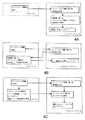
図4Aには、システム100の動作を示すフローチャートが示されている。まず、クライアント310がシステムコントローラ300にプリントジョブ情報を送る。システムコントローラは、そのプリントジョブの特性(例えば、文字とグラフィックとの割合や、用いられる基体およびインクのタイプ等といった、プリントされる画像の性質)に基づいて、プロセス方向解像度を決定する。ウェブ方向解像度が決定されたら、システムコントローラは、プリントジョブ情報にRIPを行って、発射指示を供給する。最後に、システムが、画素トリガ信号を用いてゲート制御される発射指示を用いてプリントを行うことで、プリントジョブが実行される。 FIG. 4A shows a flowchart showing the operation of the system 100. First, the
上述の実施形態では、システムコントローラはプリントジョブ情報にRIPを行って発射指示を生成する。しかし、クライアントとシステムコントローラとの間でタスクを分割すると、上述の動作モードとは異なるものになり得る。例えば、幾つかの実施形態では、システムコントローラにプリントジョブ情報を送る代わりに、クライアントがプリントジョブ情報にRIPを行って、発射指示を送ることができる。 In the above-described embodiment, the system controller performs RIP on the print job information to generate a firing instruction. However, dividing the task between the client and the system controller can be different from the operation mode described above. For example, in some embodiments, instead of sending print job information to the system controller, the client can RIP the print job information and send a firing instruction.
図4Bにはこの動作モードの一例が示されており、ここでは、クライアントがシステムコントローラにプリントジョブ情報を送る。システムコントローラは、プリントジョブデータにRIPを行う代わりに、用いる解像度を決定すし、この情報をクライアントに供給する。クライアントは、選択された解像度に従ってプリントジョブ情報にRIPを行うことにより、発射指示を生成し、これがシステムコントローラに送られる。システムコントローラは、発射指示に従ってプリントジョブを実行する。 FIG. 4B shows an example of this operation mode, in which the client sends print job information to the system controller. Instead of RIPing the print job data, the system controller determines the resolution to be used and supplies this information to the client. The client generates a firing instruction by RIPing the print job information according to the selected resolution, which is sent to the system controller. The system controller executes a print job according to the firing instruction.
図4Cのフロー図には、別の動作モードの更に別の例が示されている。この実施形態では、クライアントはシステムコントローラにプリントジョブ情報を供給すると共に、プリントジョブ情報にRIPを行って、複数のプリント解像度における複数のセット(例えば、3、4、5セット以上)の発射指示を供給する。例えば、クライアントは、プリントジョブ情報にRIPを行って、300dpi、600dpi、および900dpiでプリントするための発射指示を供給してもよい。システムコントローラは、プリントジョブ情報に基づいて、そのプリントジョブに対する適切な解像度を選択し、クライアントから対応する発射指示を受け取る。対応する発射指示を用いて、選択された解像度でプリントジョブが実行される。 Still another example of another mode of operation is shown in the flow diagram of FIG. 4C. In this embodiment, the client supplies print job information to the system controller and performs RIP on the print job information to issue firing instructions for a plurality of sets (eg, 3, 4, 5 or more sets) at a plurality of print resolutions. Supply. For example, the client may RIP the print job information and provide firing instructions for printing at 300 dpi, 600 dpi, and 900 dpi. Based on the print job information, the system controller selects an appropriate resolution for the print job and receives a corresponding firing instruction from the client. A print job is executed at the selected resolution using the corresponding firing instruction.
或いは、プリントジョブ情報と共に、複数のセットの発射指示が、システムコントローラに送られてもよい。複数のセットの発射指示はメモリにバッファされる。プリントジョブを実行するために、選択された解像度に対応する発射指示のみがアクセスされる。この場合には、システムコントローラ内のメモリバッファは、複数のセット(例えば、2セット、3セット、4セット、5セット以上)の発射指示を格納するために十分な大きさを有するべきである。例えば、画像が約10メガバイトのメモリに対応し、3セットの発射指示が生成される場合には、メモリバッファの容量は約30メガバイト以上であるべきである。幾つかの実施形態では、メモリバッファは、約1ギガバイト以上(例えば、約3ギガバイト以上、約5ギガバイト以上、約10ギガバイト以上、約20ギガバイト以上、約50ギガバイト以上)であり得る。 Alternatively, multiple sets of firing instructions may be sent to the system controller along with the print job information. Multiple sets of firing instructions are buffered in memory. Only the firing instructions corresponding to the selected resolution are accessed to execute the print job. In this case, the memory buffer in the system controller should be large enough to store multiple sets of firing instructions (eg, 2 sets, 3 sets, 4 sets, 5 sets or more). For example, if an image corresponds to about 10 megabytes of memory and three sets of firing instructions are generated, the memory buffer capacity should be about 30 megabytes or more. In some embodiments, the memory buffer may be about 1 gigabyte or more (eg, about 3 gigabyte or more, about 5 gigabyte or more, about 10 gigabyte or more, about 20 gigabyte or more, about 50 gigabyte or more).
ジェット射出周波数は、システムコントローラによって画素トリガ信号を介して制御され、一般的に、これらの電子的要素および/またはプリントヘッドの物理的および電気的特性によって制限される。ジェット射出周波数は、例えば約5kHzから約100kHzまで変化させることができる。幾つかの実施形態では、ジェット射出周波数は約15kHz〜25kHzである。 The jet firing frequency is controlled by the system controller via a pixel trigger signal and is generally limited by these electronic elements and / or the physical and electrical characteristics of the printhead. The jet injection frequency can vary, for example, from about 5 kHz to about 100 kHz. In some embodiments, the jet injection frequency is about 15 kHz to 25 kHz.
ウェブ速度も、システムコントローラによってウェブコントローラを介して制御される。最小ウェブ速度は、一般的に、ウェブ操作装置がウェブを安定に保つ能力によって制限される。非常に低速である場合には、ウェブ操作装置が、ウェブに、液滴配置エラーを生じるような動きを生じさせ得る。そのような振動は、非常に高速である場合にも生じ得るが、最大ウェブ速度は、1つのステーションにおけるウェブの最小滞留時間等のように、プロセス工程の1つによって決定されることが多い。この一例として、UV硬化インクについては、インクを適切に硬化させるのに必要な最小露光に従って最大ウェブ速度が決定され得る。幾つかの実施形態では、ウェブ速度を約0.1ms−1〜10ms−1の範囲(例えば、約1ms−1〜3ms−1の範囲)で変えることができる。Web speed is also controlled by the system controller via the web controller. The minimum web speed is generally limited by the ability of the web manipulator to keep the web stable. If very slow, the web manipulator may cause the web to move in such a way as to cause a drop placement error. Such vibrations can occur even at very high speeds, but the maximum web speed is often determined by one of the process steps, such as the minimum residence time of the web at one station. As an example of this, for UV curable inks, the maximum web speed can be determined according to the minimum exposure required to properly cure the ink. In some embodiments, it is possible to change the web speed in the range of about0.1ms-1~10ms -1 (e.g., range from about1ms-1~3ms -1).
本発明の複数の実施形態を説明した。しかし、本発明の精神および範囲から逸脱することなく、様々な変形が行われ得ることを理解されたい。他の実施形態も特許請求の範囲の範囲内である。 A number of embodiments of the invention have been described. However, it should be understood that various modifications can be made without departing from the spirit and scope of the invention. Other embodiments are within the scope of the claims.
Claims (14)
Translated fromJapanese基体と、インクタイプと、基体およびインクタイプの各組み合わせに対してイメージ品質を最適化する対応するプロセス方向解像度とのデータベースを含むルックアップテーブルを用い、基体の組成およびインクの特性に基づいてプリントシステムのノズルにより噴出されるべき液滴のサイズを選択する工程と、
選択された液滴のサイズに基づいてプリントシステムに対する発射指示を生成する工程であって、液滴の選択が細かい規模のレイダウン調節の提供を含む工程と、
を有してなることを特徴とする方法。A printing system receiving information about the print job identifying the composition of the substrate and the characteristics of the ink associated with the diffusion of the ink on the substrate;
Print based on substrate composition and ink characteristics using a look-up table containing a database of substrates, ink types, and corresponding process direction resolutions that optimize image quality for each substrate and ink type combination Selecting the size of the droplets to be ejected by the nozzles of the system;
Generating firing instructions for the printing system based on the selected droplet size, wherein droplet selection includes providing fine-scale laydown adjustments;
A method comprising the steps of:
前記プリントヘッドと基体との相対移動を生じさせる移送装置と、
前記プリントヘッドと通信し、かつ、前記プリントヘッドのノズルから射出されるインクの液滴のサイズを、基体の組成およびインクの特性に基づいて選択し、選択された液滴のサイズに基づいて発射指示を生成するように構成された射出コントローラであって、基体と、インクタイプと、基体およびインクタイプの各組み合わせに対してイメージ品質を最適化する対応するプロセス方向解像度とのデータベースを含む射出コントローラとを備えたことを特徴とするプリントシステム。Print head,
A transfer device for causing relative movement between the print head and the substrate;
The size of the ink droplet that communicates with the print head and is ejected from the nozzle of the print head is selected based on the composition of the substrate and the characteristics of the ink, and fired based on the size of the selected droplet An injection controller configured to generate an indication comprising a database of substrates, ink types, and corresponding process direction resolutions that optimize image quality for each substrate and ink type combination A printing system characterized by comprising:
Applications Claiming Priority (2)
| Application Number | Priority Date | Filing Date | Title |
|---|---|---|---|
| US60775304P | 2004-09-07 | 2004-09-07 | |
| US60/607,753 | 2004-09-07 |
Related Parent Applications (1)
| Application Number | Title | Priority Date | Filing Date |
|---|---|---|---|
| JP2007531271ADivisionJP2008513233A (en) | 2004-09-07 | 2005-08-31 | Variable resolution in printing system and printing method |
Publications (1)
| Publication Number | Publication Date |
|---|---|
| JP2013060019Atrue JP2013060019A (en) | 2013-04-04 |
Family
ID=36036955
Family Applications (2)
| Application Number | Title | Priority Date | Filing Date |
|---|---|---|---|
| JP2007531271APendingJP2008513233A (en) | 2004-09-07 | 2005-08-31 | Variable resolution in printing system and printing method |
| JP2012262140APendingJP2013060019A (en) | 2004-09-07 | 2012-11-30 | Printing system and method |
Family Applications Before (1)
| Application Number | Title | Priority Date | Filing Date |
|---|---|---|---|
| JP2007531271APendingJP2008513233A (en) | 2004-09-07 | 2005-08-31 | Variable resolution in printing system and printing method |
Country Status (6)
| Country | Link |
|---|---|
| US (2) | US20060061791A1 (en) |
| EP (1) | EP1787189B1 (en) |
| JP (2) | JP2008513233A (en) |
| KR (1) | KR101211016B1 (en) |
| CN (1) | CN101432682B (en) |
| WO (1) | WO2006029164A2 (en) |
Families Citing this family (8)
| Publication number | Priority date | Publication date | Assignee | Title |
|---|---|---|---|---|
| US6838589B2 (en) | 2003-02-19 | 2005-01-04 | 3M Innovative Properties Company | Conformable wound dressing |
| US8452725B2 (en)* | 2008-09-03 | 2013-05-28 | Hamid Hatami-Hanza | System and method of ontological subject mapping for knowledge processing applications |
| DE102007044947A1 (en)* | 2007-09-20 | 2009-04-02 | Manroland Ag | A method of reducing a punch-through effect on inkjet prints on thin substrates |
| US8581017B2 (en)* | 2008-10-24 | 2013-11-12 | 3M Innovative Properties Company | Conformable wound dressing |
| FR2940627B1 (en)* | 2008-12-30 | 2014-09-12 | Mgi France | INK JET PRINTING DEVICE OF A VARNISH COMPOSITION FOR A PRINTED SUBSTRATE. |
| JP5369955B2 (en)* | 2009-07-15 | 2013-12-18 | ミツミ電機株式会社 | Wireless communication device and mobile communication terminal |
| JP5600662B2 (en)* | 2010-12-15 | 2014-10-01 | 日本特殊陶業株式会社 | Method for forming conductor pattern |
| US8939546B2 (en) | 2012-07-12 | 2015-01-27 | Hewlett-Packard Industrial Printing Ltd. | Coordinated printhead operation |
Citations (4)
| Publication number | Priority date | Publication date | Assignee | Title |
|---|---|---|---|---|
| JPH0970965A (en)* | 1995-09-08 | 1997-03-18 | Fuji Photo Film Co Ltd | Ink jet recording apparatus |
| JPH0985964A (en)* | 1995-09-21 | 1997-03-31 | Fuji Photo Film Co Ltd | Ink-jet recording apparatus |
| JP2001078128A (en)* | 1999-09-06 | 2001-03-23 | Fuji Photo Film Co Ltd | Camera with printer |
| JP2002111947A (en)* | 2000-09-27 | 2002-04-12 | Canon Inc | Image processing apparatus and method |
Family Cites Families (33)
| Publication number | Priority date | Publication date | Assignee | Title |
|---|---|---|---|---|
| US4825227A (en)* | 1988-02-29 | 1989-04-25 | Spectra, Inc. | Shear mode transducer for ink jet systems |
| JPH02145358A (en)* | 1988-11-28 | 1990-06-04 | Canon Inc | Registration correction device |
| US4937598A (en)* | 1989-03-06 | 1990-06-26 | Spectra, Inc. | Ink supply system for an ink jet head |
| CH677042A5 (en)* | 1989-10-27 | 1991-03-28 | Chetjack Ltd | |
| US5265315A (en)* | 1990-11-20 | 1993-11-30 | Spectra, Inc. | Method of making a thin-film transducer ink jet head |
| US5841552A (en)* | 1991-04-19 | 1998-11-24 | Canon Kabushiki Kaisha | Image processed apparatus for processing images having different resolutions |
| EP0570167B1 (en)* | 1992-05-11 | 1997-01-22 | Hewlett-Packard Company | Method and apparatus for regulating print density in an ink-jet printer |
| JPH068417A (en)* | 1992-06-26 | 1994-01-18 | Canon Inc | Inkjet recording device |
| US5365843A (en)* | 1993-05-26 | 1994-11-22 | Heidelberg Druckmaschinen Ag | Printing press with web breaking assembly |
| JP3271731B2 (en)* | 1994-06-28 | 2002-04-08 | キヤノン株式会社 | Ink jet recording method and recording apparatus |
| JPH0918049A (en)* | 1995-06-30 | 1997-01-17 | Furukawa Electric Co Ltd:The | Semiconductor light receiving element |
| JPH09118049A (en)* | 1995-10-24 | 1997-05-06 | Matsushita Electric Ind Co Ltd | Printing device |
| JPH09123431A (en)* | 1995-10-26 | 1997-05-13 | Mita Ind Co Ltd | Ink jet recorder |
| JP3858344B2 (en)* | 1997-05-23 | 2006-12-13 | ブラザー工業株式会社 | Printing method and printing apparatus |
| JP4037011B2 (en)* | 1998-11-05 | 2008-01-23 | 株式会社リコー | Printer selection device, printer selection method, and storage medium |
| JP2000287075A (en)* | 1999-03-31 | 2000-10-13 | Canon Inc | Image processing method and apparatus |
| US6631976B2 (en)* | 1999-04-14 | 2003-10-14 | Canon Kabushiki Kaisha | Control of ink jet nozzle prefiring |
| IT1310121B1 (en)* | 1999-07-19 | 2002-02-11 | Olivetti Lexikon Spa | METHOD FOR DETECTION OF DROPS INJECTED FROM A THERMAL INKJET PRINTING HEAD, AND RELATED PRINTER WITH |
| JP2001205827A (en)* | 1999-11-19 | 2001-07-31 | Canon Inc | Ink jet recording method, ink jet recording apparatus, computer readable storage medium, and program |
| JP2002086853A (en) | 2000-09-11 | 2002-03-26 | Canon Inc | Information processing apparatus and system, control method therefor, peripheral device, and printer driver |
| JP2002103582A (en)* | 2000-09-27 | 2002-04-09 | Seiko Epson Corp | Printing on the surface layer of data recording media |
| US6783203B2 (en)* | 2001-05-11 | 2004-08-31 | Seiko Epson Corporation | Printing with multiple pixels as unit of gradation reproduction |
| JP2003011458A (en)* | 2001-07-03 | 2003-01-15 | Seiko Epson Corp | Printing in which the print mode is set according to the information included in the image data |
| JP2003019789A (en)* | 2001-07-06 | 2003-01-21 | Hitachi Koki Co Ltd | Inkjet recording device |
| US6776468B2 (en)* | 2001-08-27 | 2004-08-17 | Eastman Kodak Company | Method and apparatus of optimizing discrete drop volumes for multidrop capable inkjet printers |
| JP3915507B2 (en)* | 2001-12-25 | 2007-05-16 | セイコーエプソン株式会社 | Printing that suppresses blurring of contours |
| US6837562B2 (en)* | 2002-02-04 | 2005-01-04 | Seiko Epson Corporation | Printing apparatus and printing method |
| JP2003274162A (en)* | 2002-03-15 | 2003-09-26 | Ricoh Co Ltd | Image recording device |
| JP3879580B2 (en) | 2002-04-23 | 2007-02-14 | 松下電工株式会社 | Ultrasonic vibration amplitude measuring device |
| US7052117B2 (en)* | 2002-07-03 | 2006-05-30 | Dimatix, Inc. | Printhead having a thin pre-fired piezoelectric layer |
| JP2004082602A (en)* | 2002-08-28 | 2004-03-18 | Ricoh Co Ltd | Printer device |
| US6702425B1 (en)* | 2002-09-23 | 2004-03-09 | Eastman Kodak Company | Coalescence-free inkjet printing by controlling drop spreading on/in a receiver |
| JP3719263B2 (en)* | 2004-04-12 | 2005-11-24 | セイコーエプソン株式会社 | Inkjet recording device |
- 2005
- 2005-08-31JPJP2007531271Apatent/JP2008513233A/enactivePending
- 2005-08-31USUS11/220,113patent/US20060061791A1/ennot_activeAbandoned
- 2005-08-31CNCN200580030029.3Apatent/CN101432682B/ennot_activeExpired - Fee Related
- 2005-08-31EPEP05796089.0Apatent/EP1787189B1/ennot_activeExpired - Lifetime
- 2005-08-31WOPCT/US2005/031733patent/WO2006029164A2/enactiveApplication Filing
- 2005-08-31KRKR1020077006026Apatent/KR101211016B1/ennot_activeExpired - Fee Related
- 2009
- 2009-12-22USUS12/644,699patent/US8393697B2/ennot_activeExpired - Fee Related
- 2012
- 2012-11-30JPJP2012262140Apatent/JP2013060019A/enactivePending
Patent Citations (4)
| Publication number | Priority date | Publication date | Assignee | Title |
|---|---|---|---|---|
| JPH0970965A (en)* | 1995-09-08 | 1997-03-18 | Fuji Photo Film Co Ltd | Ink jet recording apparatus |
| JPH0985964A (en)* | 1995-09-21 | 1997-03-31 | Fuji Photo Film Co Ltd | Ink-jet recording apparatus |
| JP2001078128A (en)* | 1999-09-06 | 2001-03-23 | Fuji Photo Film Co Ltd | Camera with printer |
| JP2002111947A (en)* | 2000-09-27 | 2002-04-12 | Canon Inc | Image processing apparatus and method |
Also Published As
| Publication number | Publication date |
|---|---|
| JP2008513233A (en) | 2008-05-01 |
| US8393697B2 (en) | 2013-03-12 |
| EP1787189A4 (en) | 2011-08-10 |
| KR20070049216A (en) | 2007-05-10 |
| EP1787189A2 (en) | 2007-05-23 |
| EP1787189B1 (en) | 2013-10-09 |
| KR101211016B1 (en) | 2012-12-11 |
| US20060061791A1 (en) | 2006-03-23 |
| CN101432682B (en) | 2014-08-20 |
| CN101432682A (en) | 2009-05-13 |
| US20100165031A1 (en) | 2010-07-01 |
| WO2006029164A3 (en) | 2009-05-28 |
| WO2006029164A2 (en) | 2006-03-16 |
Similar Documents
| Publication | Publication Date | Title |
|---|---|---|
| JP2013060019A (en) | Printing system and method | |
| US6464316B1 (en) | Bi-directional printmode for improved edge quality | |
| US5473351A (en) | Method and apparatus for regulating print density in an ink-jet printer | |
| KR100358637B1 (en) | Controlling pwa inkjet nozzle timing as a fuction of media speed | |
| US7748829B2 (en) | Adjustable drop placement printing method | |
| US8608278B2 (en) | Direct marking printer having a user configurable print resolution | |
| US6050675A (en) | Method for operating an ink jet printer and ink jet printer using the method | |
| JP4909459B2 (en) | Pixel array press | |
| US20080303852A1 (en) | Halftone printing on an inkjet printer | |
| JP2011098455A (en) | Liquid ejector | |
| EP1683639B1 (en) | Printing system and method of printing an image in a fixed head printing system | |
| US6439686B2 (en) | Ink jet printer having apparatus for reducing systematic print quality defects | |
| JP2021000763A (en) | Head drive device, liquid ejection device and head drive method | |
| CN1454149A (en) | Ink jet fault tolerance using extra ink dots | |
| US9352595B2 (en) | Image forming apparatus and image forming method | |
| US20090009551A1 (en) | Liquid Ejecting Apparatus and Method of Ejecting Liquid | |
| JP2001270094A (en) | Printing considering the deformation of print media | |
| US6739684B1 (en) | Burst mode printing to compensate for colorant migration | |
| JP2003326688A (en) | Multi-resolution printing method and printing device | |
| JP2004338333A (en) | Image recorder | |
| WO2012136477A1 (en) | Method for controlling droplet ejection from an inkjet print head |
Legal Events
| Date | Code | Title | Description |
|---|---|---|---|
| A521 | Request for written amendment filed | Free format text:JAPANESE INTERMEDIATE CODE: A523 Effective date:20130104 | |
| A621 | Written request for application examination | Free format text:JAPANESE INTERMEDIATE CODE: A621 Effective date:20130104 | |
| A601 | Written request for extension of time | Free format text:JAPANESE INTERMEDIATE CODE: A601 Effective date:20140219 | |
| A602 | Written permission of extension of time | Free format text:JAPANESE INTERMEDIATE CODE: A602 Effective date:20140224 | |
| A521 | Request for written amendment filed | Free format text:JAPANESE INTERMEDIATE CODE: A523 Effective date:20140516 | |
| A02 | Decision of refusal | Free format text:JAPANESE INTERMEDIATE CODE: A02 Effective date:20140826 |