JP2013050113A - Blower - Google Patents
BlowerDownload PDFInfo
- Publication number
- JP2013050113A JP2013050113AJP2012269570AJP2012269570AJP2013050113AJP 2013050113 AJP2013050113 AJP 2013050113AJP 2012269570 AJP2012269570 AJP 2012269570AJP 2012269570 AJP2012269570 AJP 2012269570AJP 2013050113 AJP2013050113 AJP 2013050113A
- Authority
- JP
- Japan
- Prior art keywords
- air flow
- duct
- nozzle
- base
- air
- Prior art date
- Legal status (The legal status is an assumption and is not a legal conclusion. Google has not performed a legal analysis and makes no representation as to the accuracy of the status listed.)
- Pending
Links
- NJPPVKZQTLUDBO-UHFFFAOYSA-NnovaluronChemical compoundC1=C(Cl)C(OC(F)(F)C(OC(F)(F)F)F)=CC=C1NC(=O)NC(=O)C1=C(F)C=CC=C1FNJPPVKZQTLUDBO-UHFFFAOYSA-N0.000claimsabstractdescription41
- 238000007599dischargingMethods0.000claimsdescription5
- 230000002093peripheral effectEffects0.000description12
- 230000007246mechanismEffects0.000description9
- 230000008878couplingEffects0.000description5
- 238000010168coupling processMethods0.000description5
- 238000005859coupling reactionMethods0.000description5
- 230000000694effectsEffects0.000description4
- 239000012530fluidSubstances0.000description4
- 125000006850spacer groupChemical group0.000description4
- OKTJSMMVPCPJKN-UHFFFAOYSA-NCarbonChemical compound[C]OKTJSMMVPCPJKN-UHFFFAOYSA-N0.000description3
- 229910052799carbonInorganic materials0.000description3
- 238000001816coolingMethods0.000description3
- 239000006260foamSubstances0.000description3
- 230000004044responseEffects0.000description3
- 241000954177Bangana arizaSpecies0.000description2
- 239000000853adhesiveSubstances0.000description2
- 230000001070adhesive effectEffects0.000description2
- 230000006835compressionEffects0.000description2
- 238000007906compressionMethods0.000description2
- 230000005484gravityEffects0.000description2
- 230000006698inductionEffects0.000description2
- 230000009467reductionEffects0.000description2
- 229910000831SteelInorganic materials0.000description1
- 208000027418Wounds and injuryDiseases0.000description1
- 230000000172allergic effectEffects0.000description1
- 208000010668atopic eczemaDiseases0.000description1
- 230000006378damageEffects0.000description1
- 238000001704evaporationMethods0.000description1
- 230000008020evaporationEffects0.000description1
- 239000006261foam materialSubstances0.000description1
- 230000030279gene silencingEffects0.000description1
- 208000014674injuryDiseases0.000description1
- 239000000463materialSubstances0.000description1
- 238000000034methodMethods0.000description1
- 238000007789sealingMethods0.000description1
- 239000010959steelSubstances0.000description1
- 238000009827uniform distributionMethods0.000description1
- 239000002699waste materialSubstances0.000description1
Images


Classifications
- F—MECHANICAL ENGINEERING; LIGHTING; HEATING; WEAPONS; BLASTING
- F04—POSITIVE - DISPLACEMENT MACHINES FOR LIQUIDS; PUMPS FOR LIQUIDS OR ELASTIC FLUIDS
- F04D—NON-POSITIVE-DISPLACEMENT PUMPS
- F04D25/00—Pumping installations or systems
- F04D25/02—Units comprising pumps and their driving means
- F04D25/08—Units comprising pumps and their driving means the working fluid being air, e.g. for ventilation
- F04D25/10—Units comprising pumps and their driving means the working fluid being air, e.g. for ventilation the unit having provisions for automatically changing direction of output air
- F—MECHANICAL ENGINEERING; LIGHTING; HEATING; WEAPONS; BLASTING
- F04—POSITIVE - DISPLACEMENT MACHINES FOR LIQUIDS; PUMPS FOR LIQUIDS OR ELASTIC FLUIDS
- F04D—NON-POSITIVE-DISPLACEMENT PUMPS
- F04D25/00—Pumping installations or systems
- F04D25/02—Units comprising pumps and their driving means
- F04D25/06—Units comprising pumps and their driving means the pump being electrically driven
- F—MECHANICAL ENGINEERING; LIGHTING; HEATING; WEAPONS; BLASTING
- F04—POSITIVE - DISPLACEMENT MACHINES FOR LIQUIDS; PUMPS FOR LIQUIDS OR ELASTIC FLUIDS
- F04D—NON-POSITIVE-DISPLACEMENT PUMPS
- F04D29/00—Details, component parts, or accessories
- F04D29/40—Casings; Connections of working fluid
- F—MECHANICAL ENGINEERING; LIGHTING; HEATING; WEAPONS; BLASTING
- F04—POSITIVE - DISPLACEMENT MACHINES FOR LIQUIDS; PUMPS FOR LIQUIDS OR ELASTIC FLUIDS
- F04D—NON-POSITIVE-DISPLACEMENT PUMPS
- F04D29/00—Details, component parts, or accessories
- F04D29/40—Casings; Connections of working fluid
- F04D29/403—Casings; Connections of working fluid especially adapted for elastic fluid pumps
- F—MECHANICAL ENGINEERING; LIGHTING; HEATING; WEAPONS; BLASTING
- F04—POSITIVE - DISPLACEMENT MACHINES FOR LIQUIDS; PUMPS FOR LIQUIDS OR ELASTIC FLUIDS
- F04D—NON-POSITIVE-DISPLACEMENT PUMPS
- F04D29/00—Details, component parts, or accessories
- F04D29/40—Casings; Connections of working fluid
- F04D29/42—Casings; Connections of working fluid for radial or helico-centrifugal pumps
- F04D29/44—Fluid-guiding means, e.g. diffusers
- F—MECHANICAL ENGINEERING; LIGHTING; HEATING; WEAPONS; BLASTING
- F04—POSITIVE - DISPLACEMENT MACHINES FOR LIQUIDS; PUMPS FOR LIQUIDS OR ELASTIC FLUIDS
- F04F—PUMPING OF FLUID BY DIRECT CONTACT OF ANOTHER FLUID OR BY USING INERTIA OF FLUID TO BE PUMPED; SIPHONS
- F04F5/00—Jet pumps, i.e. devices in which flow is induced by pressure drop caused by velocity of another fluid flow
- F04F5/14—Jet pumps, i.e. devices in which flow is induced by pressure drop caused by velocity of another fluid flow the inducing fluid being elastic fluid
- F04F5/16—Jet pumps, i.e. devices in which flow is induced by pressure drop caused by velocity of another fluid flow the inducing fluid being elastic fluid displacing elastic fluids
- F—MECHANICAL ENGINEERING; LIGHTING; HEATING; WEAPONS; BLASTING
- F24—HEATING; RANGES; VENTILATING
- F24F—AIR-CONDITIONING; AIR-HUMIDIFICATION; VENTILATION; USE OF AIR CURRENTS FOR SCREENING
- F24F13/00—Details common to, or for air-conditioning, air-humidification, ventilation or use of air currents for screening
- F24F13/32—Supports for air-conditioning, air-humidification or ventilation units
- F—MECHANICAL ENGINEERING; LIGHTING; HEATING; WEAPONS; BLASTING
- F24—HEATING; RANGES; VENTILATING
- F24F—AIR-CONDITIONING; AIR-HUMIDIFICATION; VENTILATION; USE OF AIR CURRENTS FOR SCREENING
- F24F7/00—Ventilation
- F24F7/04—Ventilation with ducting systems, e.g. by double walls; with natural circulation
- F24F7/06—Ventilation with ducting systems, e.g. by double walls; with natural circulation with forced air circulation, e.g. by fan positioning of a ventilator in or against a conduit
- F24F7/065—Ventilation with ducting systems, e.g. by double walls; with natural circulation with forced air circulation, e.g. by fan positioning of a ventilator in or against a conduit fan combined with single duct; mounting arrangements of a fan in a duct
- F—MECHANICAL ENGINEERING; LIGHTING; HEATING; WEAPONS; BLASTING
- F24—HEATING; RANGES; VENTILATING
- F24F—AIR-CONDITIONING; AIR-HUMIDIFICATION; VENTILATION; USE OF AIR CURRENTS FOR SCREENING
- F24F2221/00—Details or features not otherwise provided for
- F24F2221/28—Details or features not otherwise provided for using the Coanda effect
Landscapes
- Engineering & Computer Science (AREA)
- Mechanical Engineering (AREA)
- General Engineering & Computer Science (AREA)
- Chemical & Material Sciences (AREA)
- Combustion & Propulsion (AREA)
- Physics & Mathematics (AREA)
- Fluid Mechanics (AREA)
- Structures Of Non-Positive Displacement Pumps (AREA)
- Jet Pumps And Other Pumps (AREA)
- Drying Of Solid Materials (AREA)
Abstract
Translated fromJapaneseDescription
Translated fromJapanese本発明は、送風機に関する。好ましい実施形態において、本発明は、室内、事務所内、及び他の家庭内(屋内)環境において気流を生成するための台座送風機に関する。 The present invention relates to a blower. In a preferred embodiment, the present invention relates to a pedestal blower for generating airflow in indoor, office, and other domestic (indoor) environments.
従来の家庭用(屋内型)送風機またはファンは、典型的には、軸の周りを回転するように取り付けられた一組の羽根又はベーンと、羽根の組を回転させて空気流を生成するための駆動装置とを含む。空気流の動き及び循環により「風冷」又は微風が生成され、結果として、対流及び蒸発により熱が放散されるため、ユーザは冷却効果を体験する。 Conventional home (indoor) blowers or fans typically have a set of vanes or vanes mounted to rotate about an axis and a set of vanes to rotate to generate an air flow. Drive device. The user experiences a cooling effect because “wind cooling” or breeze is generated by the movement and circulation of the air flow and as a result, heat is dissipated by convection and evaporation.
このようなファンは、種々のサイズ及び形状で入手可能である。例えば、天井ファンの直径は、少なくとも1mとすることができ、通常は天井から吊下げ式に取り付けられ、部屋を冷却するための下向きの気流を与える。一方、卓上ファンの直径は、多くの場合、約30cmであり、通常は自立型及び携帯型である。床置き型台座ファンは、一般に、駆動装置を支持する高さ調節可能な台座と、通常300l/sから500l/sまでの空気流を生成するための羽根の組とを含む。 Such fans are available in various sizes and shapes. For example, the ceiling fan can have a diameter of at least 1 m and is usually mounted suspended from the ceiling to provide a downward airflow to cool the room. On the other hand, the diameter of a desk fan is about 30 cm in many cases, and is usually free-standing and portable. Floor-standing pedestal fans generally include a height-adjustable pedestal that supports the drive and a set of blades for generating an air flow typically between 300 l / s and 500 l / s.
このタイプの構成の不利な点は、ファンの回転羽根によって生成される空気流が、通常、均一でないことである。これは、羽根表面にわたる又はファンの外側面にわたるばらつきが原因である。このばらつきの程度は、製品ごとに異なり、個々のファン機械毎に異なることさえある。このばらつきは、結果として、一連の空気のパルスとして感じられ、ユーザにとっては不快なものであり得る、不均一な又は「不規則に変化する」空気流の生成をもたらす。 A disadvantage of this type of configuration is that the air flow generated by the fan blades is usually not uniform. This is due to variations across the blade surface or across the outside surface of the fan. The degree of this variation varies from product to product and can even vary from one fan machine to another. This variation results in the generation of a non-uniform or “irregularly changing” air flow that can be felt as a series of air pulses and can be uncomfortable for the user.
家庭環境では、電気器具の部品が外向きに突出していること、又は、ユーザが羽根のような可動部品に触れることができることは望ましくない。台座ファンは、回転羽根との接触による怪我を防止するために、羽根の周囲にケージを有する傾向があるが、そのようなケージに入れられた部品は、清掃が困難であり得る。さらに、台座の上に駆動装置及び回転羽根を取り付けるため、台座ファンの重心が、通常、台座の上の方に位置することになる。このことは、台座に比較的広い又は重い基部が設けられていない限り、誤ってぶつかった場合に、台座ファンが転倒しやすくなることがあり、このことは、ユーザにとって望ましくない。 In a home environment, it is not desirable that the parts of the appliance protrude outward or that the user can touch a moving part such as a wing. Pedestal fans tend to have a cage around the blades to prevent injury due to contact with the rotating blades, but the parts contained in such cages can be difficult to clean. Further, since the driving device and the rotary blade are mounted on the pedestal, the center of gravity of the pedestal fan is usually located on the upper side of the pedestal. This can make the pedestal fan tip over if accidentally bumped, unless the pedestal has a relatively wide or heavy base, which is undesirable for the user.
第1の態様において、本発明は、空気流を生成するための床置き型台座ファン又は送風機を提供し、このファンは、空気流を生成するための手段と、空気出口と、空気流を空気出口に運ぶための伸縮式ダクトとを含む。 In a first aspect, the present invention provides a floor-standing pedestal fan or blower for generating an air flow, the fan comprising means for generating an air flow, an air outlet, and an air flow. Telescopic duct for carrying to the outlet.
空気流を生成するための手段は、インペラと、インペラを回転させるモータとを含むことが好ましく、インペラの下流に配置されたディフューザをさらに含むことが好ましい。ファンは、基部、好ましくは床置き型基部を含み、ダクトが、基部と空気出口との間に延びていることが好ましい。基部は、空気流を生成するための手段を収容することが好ましい。従って、第2の態様において、本発明は、インペラ及び空気流を生成するためにインペラを回転させるモータを収容する基部と、空気出口と、空気流を空気出口に運ぶための伸縮式ダクトとを含む台座ファンを提供する。 The means for generating the air flow preferably includes an impeller and a motor that rotates the impeller, and preferably further includes a diffuser disposed downstream of the impeller. The fan preferably includes a base, preferably a floor-standing base, and the duct extends between the base and the air outlet. The base preferably contains a means for generating an air flow. Thus, in a second aspect, the present invention comprises an impeller and a base that houses a motor that rotates the impeller to generate an air flow, an air outlet, and a telescopic duct for carrying the air flow to the air outlet. Provide pedestal fans including.
従って、本発明において、伸縮式ダクトは、ファン組立体により生成された空気流が放出される空気出口を支持する役割、及び、生成された空気流を空気出口に運ぶ役割の両方を果たす。従って、空気流を生成するための手段は、台座ファンの基部内に配置することができ、これにより、羽根付ファン及び羽根付ファン用の駆動装置が台座の上部に結合された従来技術の台座ファンと比較して、ファンの重心が低くなり、これによりぶつかってもファン組立体が倒れにくくなる。 Thus, in the present invention, the telescopic duct serves both to support the air outlet from which the air flow generated by the fan assembly is discharged and to carry the generated air flow to the air outlet. Thus, the means for generating the air flow can be located in the base of the pedestal fan, whereby the vane fan and the drive for the vane fan are coupled to the top of the pedestal. Compared with a fan, the center of gravity of the fan is lowered, and this makes it difficult for the fan assembly to collapse even if it hits.
モータは、摩擦損失及び従来型のブラシ式モータで使用されるブラシからの炭素ごみを回避するために、DCブラシレスモータであることが好ましい。炭素ごみ及び炭素放出の削減は、病院又はアレルギーを有する人の周囲など清浄な又は汚染に敏感な環境において有利である。一般的に台座ファンに使用される誘導モータもブラシがないが、DCブラシレスモータは、誘導モータよりもかなり広い範囲の動作速度を提供できる。インペラは、混流インペラであることが好ましい。 The motor is preferably a DC brushless motor to avoid friction loss and carbon debris from the brushes used in conventional brush motors. Reduction of carbon waste and carbon emissions is advantageous in clean or contaminated environments such as hospitals or around allergic people. In general, induction motors used for pedestal fans have no brushes, but DC brushless motors can provide a much wider range of operating speeds than induction motors. The impeller is preferably a mixed flow impeller.
基部は、インペラの下流に配置されたディフューザを収容することが好ましい。ディフューザは、該ディフューザから渦を巻く空気流の放出を結果としてもたらす、複数の渦巻き型ベーンを含むことができる。ダクトを通る空気流は、通常、軸方向又は長手方向のものであるため、ファンは、ディフューザから放出された空気流をダクトへ案内するための手段を含むことが好ましい。これにより、ファン内の伝導損失を削減できる。空気流案内手段は、ディフューザから放出された空気流のそれぞれの部分をダクトに案内するための複数のベーンを含むことが好ましい。これらのベーンは、ディフューザの上に取り付けられた空気流案内部材の内面に配置され、ほぼ等間隔で配置されることが好ましい。空気流案内手段はまた、少なくとも部分的にダクト内に配置された複数の半径方向のベーンを含み、半径方向ベーンの各々は、複数のベーンのそれぞれに隣接していることが好ましい。これらの半径方向ベーンは、各々が、複数のベーンにより定められるチャネルから気流のそれぞれの部分を受け入れる、ダクト内の軸方向又は長手方向の複数のチャネルを定めることができる。この空気流の部分は、ダクト内で合流することが好ましい。 The base preferably accommodates a diffuser disposed downstream of the impeller. The diffuser can include a plurality of spiral vanes that result in the release of a swirling air stream from the diffuser. Since the air flow through the duct is usually axial or longitudinal, the fan preferably includes means for guiding the air flow emitted from the diffuser into the duct. Thereby, the conduction loss in a fan can be reduced. The air flow guiding means preferably includes a plurality of vanes for guiding respective portions of the air flow discharged from the diffuser to the duct. These vanes are preferably arranged on the inner surface of the air flow guide member mounted on the diffuser and are arranged at substantially equal intervals. The air flow guide means also includes a plurality of radial vanes disposed at least partially within the duct, and each of the radial vanes is preferably adjacent to each of the plurality of vanes. These radial vanes may define a plurality of axial or longitudinal channels within the duct, each receiving a respective portion of the air flow from a channel defined by the plurality of vanes. This part of the air flow preferably merges in the duct.
ダクトは、台座ファンの基部に取り付けられた基部と、ダクトの基部に取り付けられた複数の管状部材とを含む。湾曲したベーンは、少なくとも部分的にダクトの基部内に配置することができる。軸方向ベーンは、少なくとも部分的に、管状部材の1つをダクトの基部に結合するための手段内に配置することができる。結合手段は、空気管、又は管状部材の1つを受け入れるための他の管状部材を含むことができる。 The duct includes a base attached to the base of the pedestal fan and a plurality of tubular members attached to the base of the duct. The curved vane can be located at least partially within the base of the duct. The axial vane can be at least partially disposed within the means for coupling one of the tubular members to the base of the duct. The coupling means may include an air tube or other tubular member for receiving one of the tubular members.
ファンは、羽根なしファン組立体の形態であることが好ましい。羽根なしファン組立体を使用することにより、羽根付ファンを使用せずに、空気流を発生させることができる。羽根付ファン組立体と比較すると、羽根なしファン組立体は、可動部品及び複雑さの両方の低減をもたらす。さらに、ファン組立体から空気流を射出するために羽根付ファンを使用しない場合、比較的一様な空気流を生成し、室内に又はユーザに向けて案内することができる。空気流は、ノズルから効果的に移動することができ、乱流によるエネルギー及び速度の損失がほとんどない。 The fan is preferably in the form of a vaneless fan assembly. By using a vaneless fan assembly, an air flow can be generated without the use of a vaned fan. Compared to a bladed fan assembly, a bladeless fan assembly provides a reduction in both moving parts and complexity. Further, if a vaned fan is not used to eject the airflow from the fan assembly, a relatively uniform airflow can be generated and guided into the room or towards the user. The air flow can effectively move from the nozzle and there is little loss of energy and velocity due to turbulence.
「羽根なし」という用語は、可動羽根を使用せずに、空気流がファン組立体から前方に放出又は射出されるファン組立体を説明するために使用される。従って、羽根なしファン組立体は、出力領域又は放出区域を有し、そこから空気流がユーザ又は室内に向けられる可動羽根は存在しないと考えることができる。羽根なしファン組立体の出力領域には、ポンプ、発電機、モータ、又は他の流体搬送装置などの種々の異なる源の1つにより生成される一次空気流を供給することができ、種々の異なる源は、空気流を生成するためのモータ回転子及び/又は羽根付インペラなどの回転装置を含むことができる。生成された一次空気流は、室内空間又はファン組立体外部の他の環境から伸縮式ダクトを通ってノズルに向かい、次にノズルの口を通って再び室内に戻ることができる。 The term “bladeless” is used to describe a fan assembly in which airflow is expelled or ejected forward from the fan assembly without the use of moving vanes. Thus, a vaneless fan assembly can be considered to have an output region or discharge area from which there are no moving vanes from which airflow is directed to the user or room. The output region of the vaneless fan assembly can be supplied with a primary air flow generated by one of a variety of different sources, such as a pump, generator, motor, or other fluid conveying device, and can be varied. The source may include a rotating device such as a motor rotor and / or a bladed impeller for generating an air flow. The generated primary air flow can travel from the interior space or other environment outside the fan assembly through the telescopic duct to the nozzle and then back into the room through the nozzle mouth.
従って、羽根なしとしてのファンの説明は、二次的ファン機能に必要なモータなどの電源及び部品の説明まで及ぶことを意図していない。二次的ファン機能の例は、ファン組立体の照明、調整及び首振りを含むことができる。 Thus, the description of a fan without vanes is not intended to extend to the description of power supplies and components such as motors required for secondary fan function. Examples of secondary fan functions can include lighting, adjusting and swinging the fan assembly.
従って、ファンの空気出口の形状は、羽根付ファン用の空間を含むという要件に制約されない。ノズルは開口部を囲むことが好ましい。例えば、空気出口は、好ましくは200mmから600mmまでの範囲、より好ましくは250mmから500mmまでの範囲の高さを有する環状ノズルとすることができる。 Thus, the shape of the fan air outlet is not constrained by the requirement to include space for the fan with vanes. The nozzle preferably surrounds the opening. For example, the air outlet can be an annular nozzle having a height preferably in the range of 200 mm to 600 mm, more preferably in the range of 250 mm to 500 mm.
空気出口は、該空気出口から放出された空気流によってノズルの外部からの空気が引き込まれる開口部の周りに延びることが好ましい。この空気出口は、空気流を放出するための口と、ダクトから空気流を受け入れ、空気流を口に運ぶための内部通路とを含むノズルの形態であることが好ましい。従って、第3の態様において、本発明は、台座上に取り付けられたノズルを含むファン組立体を提供し、この台座は、空気流を生成するための手段と、空気流をノズルに運ぶための伸縮式ダクトとを含み、ノズルは、空気流を放出するための口を含み、且つ口から放出された空気流によってノズルの外部からの空気が引き込まれる開口部の周りに延びる。 The air outlet preferably extends around an opening through which air from outside the nozzle is drawn by the air flow emitted from the air outlet. The air outlet is preferably in the form of a nozzle that includes a mouth for discharging the air flow and an internal passage for receiving the air flow from the duct and carrying the air flow to the mouth. Accordingly, in a third aspect, the present invention provides a fan assembly that includes a nozzle mounted on a pedestal, the pedestal comprising means for generating an air flow and for conveying the air flow to the nozzle. And a telescopic duct, the nozzle includes a mouth for discharging an air flow, and extends around an opening through which air from outside the nozzle is drawn by the air flow discharged from the mouth.
ノズルの口は開口部の周りに延び、かつ、環状であることが好ましい。ノズルは、ノズルの口を定める内側ケーシング区分及び外側ケーシング区分を含むことが好ましい。各区分は、それぞれの環状部材から形成されることが好ましいが、その区分を形成するために互いに結合された、又は組み立てられた複数の部材により、各区分を設けることもできる。外側ケーシング区分は、内側ケーシング区分と部分的に重なるように形成されることが好ましい。これにより、口の出口をノズルの内側ケーシング区分の外面と外側ケーシング区分の内面の重複部分の間に定めることが可能になる。出口は、スロットの形態であることが好ましく、0.5mmから5mmまでの範囲、より好ましくは0.5mmから1.5mmまでの範囲の幅を有することが好ましい。ノズルは、ノズルの内側ケーシング区分及び外側ケーシング区分の重複部分を離間させるための複数のスペーサを含むことができる。これは、開口部の周りに実質的に均一な出口幅を維持するのに役立ち得る。スペーサは、出口に沿って等間隔に配置されることが好ましい。 The nozzle mouth preferably extends around the opening and is annular. The nozzle preferably includes an inner casing section and an outer casing section that define the mouth of the nozzle. Each section is preferably formed from a respective annular member, but each section may be provided by a plurality of members joined together or assembled to form the section. The outer casing section is preferably formed to partially overlap the inner casing section. This allows a mouth outlet to be defined between the overlap of the outer surface of the inner casing section of the nozzle and the inner surface of the outer casing section. The outlet is preferably in the form of a slot and preferably has a width in the range from 0.5 mm to 5 mm, more preferably in the range from 0.5 mm to 1.5 mm. The nozzle can include a plurality of spacers for spacing overlapping portions of the inner casing section and the outer casing section of the nozzle. This can help maintain a substantially uniform exit width around the opening. The spacers are preferably arranged at equal intervals along the outlet.
ノズルは、ダクトから空気流を受け入れるための内部通路を含むことが好ましい。内部通路は、好ましくは環状であり、かつ、空気流を、開口部の周りで反対方向に流れる2つの空気流に分割するように形成されることが好ましい。内部通路はまた、ノズルの内側ケーシング部分及び外側ケーシング部分によって定められることが好ましい。 The nozzle preferably includes an internal passage for receiving an air flow from the duct. The internal passage is preferably annular and is preferably formed to divide the air flow into two air flows that flow in opposite directions around the opening. The internal passage is also preferably defined by an inner casing portion and an outer casing portion of the nozzle.
ファンは、空気流が好ましくは60°から120°までの範囲で弧を描いて吹かれるように、ノズルの首振り手段を含むことが好ましい。例えば、台座の基部は、基部の下部に対して、ノズルが結合される基部の上部の首振り手段を含むことができる。 The fan preferably includes a nozzle swing means so that the air flow is blown in an arc, preferably in the range of 60 ° to 120 °. For example, the base of the pedestal can include a swinging means at the top of the base to which the nozzle is coupled relative to the bottom of the base.
ファン組立体により生成された空気流の最大空気流量は、好ましくは毎秒300リットルから800リットルまでの範囲、より好ましくは毎秒500リットルから800リットルまでの範囲にある。 The maximum airflow generated by the fan assembly is preferably in the range of 300 to 800 liters per second, more preferably in the range of 500 to 800 liters per second.
ノズルは、口に隣接して配置され、かつ、その上で口がノズルから放出された空気流を差し向けるように構成された面、好ましくはコアンダ面を含むことができる。ノズルの内側ケーシング部分の外面は、コアンダ面を定めるように形成されることが好ましい。コアンダ面は、開口部の周りに延びることが好ましい。コアンダ面とは、その上で表面に近い出力オリフィスを出る流体流がコアンダ効果を示す既知のタイプの面である。流体は、面の上に接近し、ほとんど面に「へばりつくように」又は面を「抱きこむようにして」流れる傾向がある。コアンダ効果は、一次空気流がコアンダ面の上に差し向けられる、既に証明され多く文書化された同伴方法である。コアンダ面の特徴及びコアンダ面の上の流体流の効果の説明は、Reba、Scientific American、第214巻、1996年6月、84−92ページなどの論文に見出すことができる。コアンダ面を用いて、口から放出された空気によって、ファン組立体外部から、より多くの量の空気が開口部を通って引き込まれる。 The nozzle can include a surface, preferably a Coanda surface, disposed adjacent to the mouth and on which the mouth is configured to direct the air flow emitted from the nozzle. The outer surface of the inner casing portion of the nozzle is preferably formed so as to define a Coanda surface. The Coanda surface preferably extends around the opening. A Coanda surface is a known type of surface on which fluid flow exiting an output orifice close to the surface exhibits a Coanda effect. The fluid tends to approach the surface and flow almost “sticking” to the surface or “embracing” the surface. The Coanda effect is an already proven and well documented entrainment method in which the primary air stream is directed over the Coanda surface. A description of the characteristics of the Coanda surface and the effect of fluid flow on the Coanda surface can be found in articles such as Reba, Scientific American, 214, June 1996, pages 84-92. Using the Coanda surface, more air is drawn from the outside of the fan assembly through the opening by the air released from the mouth.
下記に説明するとおり、空気流は、伸縮式ダクトから空気出口に入る。以下の説明においては、この空気流を一次空気流と呼ぶ。一次空気流は、空気出口から放出され、コアンダ面の上を通ることが好ましい。一次空気流は、空気出口周辺の空気を同伴し、一次空気流及び同伴された空気の両方をユーザに供給する空気増幅器としての機能を果たす。同伴された空気は、本明細書では二次空気流と呼ぶ。二次空気流は、ノズルの口を囲む室内空間、領域、及び外部環境から引き込まれ、移動により、ファンの周りの他の領域からも引き込まれ、主として空気出口により定められる開口部を通過する。同伴された二次空気流と組み合わされた、コアンダ面の上に向けられた一次空気流は、空気出口から前方に放出又は射出された合計空気流量と等しい。空気出口を囲む空気の同伴により、スムーズな全体出力を維持しながら、一次空気流が少なくとも5倍に、より好ましくは少なくとも10倍に増幅されることが好ましい。 As described below, the air flow enters the air outlet from the telescoping duct. In the following description, this air flow is referred to as a primary air flow. The primary air stream is preferably discharged from the air outlet and passes over the Coanda surface. The primary air flow entrains the air around the air outlet and serves as an air amplifier that supplies both the primary air flow and the entrained air to the user. The entrained air is referred to herein as secondary air flow. The secondary air flow is drawn from the interior space, area surrounding the nozzle mouth, and the external environment, and by movement is drawn from other areas around the fan and passes through an opening defined primarily by the air outlet. The primary air flow directed above the Coanda surface combined with the entrained secondary air flow is equal to the total air flow discharged or injected forward from the air outlet. The entrainment of air surrounding the air outlet preferably amplifies the primary air flow at least 5 times, more preferably at least 10 times, while maintaining a smooth overall output.
ノズルは、コアンダ面の下流に配置されたディフューザ面を含むことが好ましい。ノズルの内側ケーシング部分の外面は、ディフューザ面を定めるように形成されることが好ましい。 The nozzle preferably includes a diffuser surface disposed downstream of the Coanda surface. The outer surface of the inner casing portion of the nozzle is preferably formed to define a diffuser surface.
本発明の第1の態様に関連して上述された特徴は、本発明の第2及び第3の態様に等しく適用可能であり、逆もまた同様である。 Features described above in connection with the first aspect of the invention are equally applicable to the second and third aspects of the invention, and vice versa.
ここで、添付する図面を参照しながら、本発明の実施形態をほんの一例として説明する。 Embodiments of the present invention will now be described by way of example only with reference to the accompanying drawings.
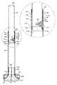
図1及び図2は、ファン組立体10の実施形態の斜視図を示す。この実施形態では、ファン組立体10は羽根なしファン組立体であり、高さ調節可能な台座12と、ファン組立体10から空気を放出するための台座12に取り付けられたノズル14とを含む家庭用(屋内型)台座ファンの形態である。台座12は、床置き型基部16と、一次空気流を基部16からノズル14に運ぶための、該基部16から上向きに延びる伸縮式ダクト18の形態の高さ調節可能なスタンドとを含む。 1 and 2 show perspective views of an embodiment of the
台座12の基部16は、ほぼ円筒形の下部ケーシング部22に取り付けられたほぼ円筒形のモータ・ケーシング部20を含む。モータ・ケーシング部20及び下部ケーシング部22は、モータ・ケーシング部20の外面が、下部ケーシング部22の外面とほぼ同一平面上にあるように、ほぼ同一の外径を有することが好ましい。下部ケーシング部22は、随意的に、床置き型円盤状基部プレート24に取り付けられ、ファン組立体10の動作を制御するための複数のユーザ操作可能ボタン26及びユーザ操作可能ダイヤル28を含む。基部16は、複数の吸気口をさらに含み、これらの吸気口は、本実施形態では、モータ・ケーシング部20内に形成された孔の形態であり、これらを通して一次空気流が外部環境から基部16内に引き込まれる。本実施形態では、台座12の基部16は、200mmから300mmまでの範囲の高さを有し、モータ・ケーシング部20は、100mmから200mmまでの範囲の直径を有する。基部プレート24は、200mmから300mmまでの範囲の直径を有することが好ましい。 The
台座12の伸縮式ダクト18は、図1に示す完全に伸長した構成と図2に示す収縮した(引っ込められた)構成との間で移動可能である。ダクト18は、ファン組立体10の基部12上に取り付けられたほぼ円筒形の基部32と、基部32に結合され、そこから上向きに延びる外側管状部材34と、部分的に外側管状部材34内に配置された内側管状部材36とを含む。コネクタ37が、ノズル14をダクト18の内側管状部材36の開放上端部に結合する。内側管状部材36は、図1に示す完全伸長位置と図2に示す収縮位置との間で、外側管状部材34に対して、かつ、その中で摺動可能である。内側管状部材36が完全伸長位置にあるとき、ファン組立体10は、1200mmから1600mmまでの範囲の高さを有することが好ましく、内側管状部材36が収縮位置にあるとき、ファン組立体10は、900mmから1300mmまでの範囲の高さを有することが好ましい。ファン組立体10の高さを調整するために、ユーザは、内側管状部材36の露出部分を握り、内側管状部材36を所望の通りに上下方向に摺動させて、ノズル14が所望する垂直方向位置になるようにする。内側管状部材36が収縮位置にあるとき、ユーザは、コネクタ37を握って内側管状部材36を上向きに引くことができる。 The
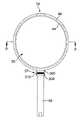
ノズル14は環形状を有し、中心軸Xを中心として延びて開口部38を定める。ノズル14は、ファン組立体10から及び開口部38を通って一次空気流を放出するための、ノズル14の後ろの方に位置している口40を含む。口40は、開口部38の周囲に延び、同じく環状であることが好ましい。ノズル14の内周部は、口40に隣接して配置され、且つこの上に口40がファン組立体10から放出された空気を向けるコアンダ面42と、コアンダ面42の下流に位置するディフューザ面44と、ディフューザ面44の下流に位置する案内面46とを含む。ディフューザ面44は、ファン組立体10から放出された空気の流れを助けるような方法で、開口部38の中心軸Xから遠ざかるようにテーパするように配置される。ディフューザ面44と開口部38の中心軸Xとの間に定められた角度は、5°から25°までの範囲であり、この例においては約7°である。案内面46は、ファン組立体10からの冷却空気流の効率的な送出をさらに助けるように、ディフューザ面44に対してある角度をなして配置される。案内面46は、口40から放出された空気流に対してほぼ平坦かつほぼ平滑な面を呈するように、開口部38の中心軸Xに対してほぼ平行に配置されることが好ましい。視覚に訴えるテーパ面48が、案内面46の下流に配置され、開口部38の中心軸Xに対してほぼ垂直に位置する先端面50で終了する。テーパ面48と開口部38の中心軸Xとの間に定められた角度は、約45°であることが好ましい。本実施形態においては、ノズル14は、400mmから600mmまでの範囲の高さを有する。 The
図3は、台座12の基部16の断面図である。基部16の下部ケーシング部22は、図1及び図2に示すユーザ操作可能ボタン26の押下げ、及び/又はユーザ操作可能ダイヤル28の操作に応答してファン組立体10の動作を制御するための、全体的に52で示す、コントローラを収容する。下部ケーシング部22は、随意的に、遠隔制御装置(図示せず)から制御信号を受信し、かつ、これら制御信号をコントローラ52に搬送するセンサ54を含むことができる。これら制御信号は、赤外線信号であることが好ましい。センサ54は、窓55の後ろに配置され、これを通って制御信号が基部16の下部ケーシング部22に入る。ファン組立体10が待機モードであるかどうかを示すための発光ダイオード(図示せず)を設けることもできる。下部ケーシング部22はまた、基部16の下部ケーシング部22に対して基部16のモータ・ケーシング部20の首振りのための、全体的に56で示す機構を収容する。首振り機構56は、下部ケーシング部22からモータ・ケーシング部20内に延びる回転可能シャフト56aを含む。シャフト56aは、軸受により下部ケーシング部22に結合されたスリーブ56b内に支持され、該シャフト56aがスリーブ56bに対して回転することを可能にする。シャフト56aの一端は、環状結合プレート56cの中央部分に結合され、結合プレート56cの外側部分は、モータ・ケーシング部20の基部に結合される。これにより、モータ・ケーシング部20を下部ケーシング部22に対して回転させることが可能になる。また、首振り機構56は、全体的に56dで示すクランクアーム機構を動作させる、下部ケーシング部22内に配置されたモータ(図示せず)も含み、クランクアーム機構56dは、下部ケーシング部22の上部に対してモータ・ケーシング部20の基部を首振りさせる。ある部分を他の部分に対して首振りさせるためのクランクアーム機構は、一般的に周知であるので、ここでは説明しない。下部ケーシング部22に対するモータ・ケーシング部20の各首振り周期の範囲は、60°から120°までの間であることが好ましく、本実施形態では約90°である。本実施形態では、首振り機構56は、毎分約3回から5回までの首振り周期を実行するよう配置される。主電源ケーブル58が、電力をファン組立体10に供給するために、下部ケーシング部22内に形成された孔を通って延びる。 FIG. 3 is a cross-sectional view of the
モータ・ケーシング部20は、台座12の基部16の吸気口30を提供するように、多くの孔62が形成された、円筒形グリル60を含む。モータ・ケーシング部20は、一次空気流を孔62を通して基部16内に引き込むためのインペラ64を収容する。インペラ64は、混流インペラの形態であることが好ましい。インペラ64は、モータ68から外向きに延びる回転シャフト66に結合される。本実施形態では、モータ68は、ダイヤル28のユーザ操作及び/又は遠隔制御装置から受信した信号に応答して、コントローラ52によって可変な速度を有するDCブラシレスモータである。モータ68の最大速度は、5,000rpmから10,000rpmまでの範囲であることが好ましい。モータ68は、下部72に結合された上部70を含むモータバケット内に収容される。モータバケットの上部70は、渦巻き型羽根を有する固定ディスクの形態のディフューザ74を含む。モータバケットは、モータ・ケーシング部20に結合された概ね切頭円錐形のインペラ・ハウジング76内に配置され、これに取り付けられる。インペラ64及びインペラ・ハウジング76は、インペラ64がインペラ・ハウジング76の内面にごく接近するが、接触しないように形成される。ほぼ環状の吸入口部材78が、一次空気流をインペラ・ハウジング76内に案内するために、インペラ・ハウジング76の底部に結合される。 The
台座12の基部16は、基部16からの騒音放出を低減させるための消音発泡材をさらに含むことが好ましい。本実施形態では、基部16のモータ・ケーシング部20は、グリル60の下方に配置された第1の環状発泡材部材80と、インペラ・ハウジング76と吸入口部材78との間に配置された第2の環状発泡材部材82とを含む。 The
ここで、図4乃至図11を参照しながら、台座12の伸縮式ダクト18をより詳細に説明する。ダクト18の基部32は、ほぼ円筒形の側壁102と、該側壁102に概ね直交し、好ましくはこれと一体の環状上面104とを含む。側壁102は、基部16のモータ・ケーシング部20とほぼ同じ外径を有し、かつ、ダクト18が基部16に結合されたとき、側壁102の外面が、基部16のモータ・ケーシング部20の外面とほぼ同一平面上になるような形状にされることが好ましい。基部32は、一次空気流をダクト18の外側管状部材34に運ぶための、外面104から上向きに延びる比較的短い空気管106をさらに含む。この空気管106は、側壁102とほぼ同軸であることが好ましく、かつ、空気管106をダクト18の外側管状部材34に完全に挿入するのを可能にするように、ダクト18の外側管状部材34の内径より僅かに小さい外形を有する。ダクト18の外側管状部材34との締まりばめを形成し、それにより外側管状部材34を基部32に固定するために、複数の軸方向に延びるリブ108を空気管106の外面上に配置することができる。環状シール部材110を空気管106の上端部に配置して、外側管状部材34と空気管106との間に気密シールを形成する。 Here, the
ダクト18は、ディフューザ74から放出された一次空気流を空気管106内に案内するためのドーム型空気案内部材114を含む。空気案内部材114は、基部16から一次空気流を受けるための開放下端部116と、一次空気流を空気管116に運ぶための開放上端部118とを有する。空気案内部材114は、ダクト18の基部32内に収容される。空気案内部材114は、基部32及び空気案内部材114上に配置された協働式スナップ嵌めコネクタ120によって、基部32に結合される。基部32と空気案内部材114との間に気密シールを形成するために、第2の環状シール部材121が、開放上端部118の周りに配置される。図3に示すように、空気案内部材114は、例えば空気案内部材114及び基部16のモータ・ケーシング部20上に配置された協働式スナップ嵌めコネクタ123又はねじ切り式コネクタの手段により、基部16のモータ・ケーシング部20の開放上端部に結合される。従って、空気案内部材114は、ダクト18を台座12の基部16に結合する役割をする。 The
複数の空気案内ベーン122が、ディフューザ74から空気管106内に放出される渦巻き状空気流を案内するために、空気案内部材114の内面上に配置される。この例では、空気案内部材114は、該空気案内部材114の内面の周りに等間隔に配置された7枚の空気案内ベーン122を含む。空気案内ベーン122は、空気案内部材114の開放上端部118の中央に集まり、従って、各々が一次空気流のそれぞれの部分を空気管106に案内するための複数の空気チャネル124を、空気案内部材114内に定める。特に図4を参照すると、7枚の半径方向の空気案内ベーン126が、空気管106内に配置されている。これら半径方向空気案内ベーン126の各々は、空気管106のほぼ全長に沿って延び、かつ、空気案内部材114が基部32に結合されると、空気案内ベーン122のそれぞれに隣接する。半径方向空気案内ベーン126は、このように空気管106内に複数の軸方向に延びる空気チャネル128を定め、その各々が、空気案内部材114内の空気チャネル124のそれぞれから一次空気流のそれぞれの部分を受け、かつ、一次空気流のその部分を空気管106を通ってダクト18の外側管状部材34内に軸方向に運ぶ。従って、基部32及びダクト18の空気案内部材114は、ディフューザ74から放出された渦巻き空気流を、外側管状部材34及び内側管状部材36を通ってノズル14に向かう軸方向の空気流に変換する役割をする。空気案内部材114とダクト18の基部32との間に気密シールを形成するために、第3の環状シール部材129を設けることができる。 A plurality of
円筒形の上部スリーブ130が、上部スリーブ130の上端部132が外側管状部材34の上端部134と同じ高さになるように、例えば接着剤又は締まりばめを用いて、外側管状部材34の上部の内面に結合される。上部スリーブ130は、内側管状部材36が上部スリーブ130を通り抜けるのを可能にするように、内側管状部材36の外径よりも僅かに大きい内径を有する。内側管状部材36と気密シールを形成するように、第3の環状シール部材136が、上部スリーブ130上に配置される。第3の環状シール部材136は、外側管状部材34の上端部132に係合して上部スリーブ130と外側管状部材34との間に気密シールを形成する環状リップ138を含む。 The cylindrical
円筒形の下部スリーブ140が、内側管状部材36の下端部142が下部スリーブ140の上端部144と下端部146との間に配置されるように、例えば接着剤又は締まりばめを用いて、内側管状部材36の下部の外面に結合される。下部スリーブ140の下端部144は、上部スリーブ130の下端部148とほぼ同じ外径を有する。従って、内側管状部材36の完全伸長位置においては、下部スリーブ140の上端部144は、上部スリーブ130の下端部148に当接し、これにより、内側管状部材36が外側管状部材34から完全に引き抜かれることが防止される。内側管状部材36の収縮位置においては、下部スリーブ140の下端部146は、空気管106の上端部に当接する。 The cylindrical
図7に示すように、ダクト18の下部スリーブ140の内向きに延びるアーム154の間に回転可能に支持される軸152の周りに、主ばね150が巻き付けられる。図8を参照すると、主ばね150は、上部スリーブ130の外面と外側管状部材34の内面との間に固定的に配置される自由端156を有する鋼帯を含む。結果的に、主ばね150は、図5及び図6に示す完全伸長位置から、図10及び図11に示す収縮位置まで内側管状部材36が下げられるのに伴って、軸152から巻き戻される。主ばね150に貯えられた弾性エネルギーは、外側管状部材34に対して内側管状部材26のユーザ選択位置を維持するための釣合い重り(カウンターウェイト)として機能する。 As shown in FIG. 7, a
好ましくはプラスチック材料から形成され、下部スリーブ140の周りに周方向に延びる環状溝160内に配置される、ばね荷重式アーチ状バンド158によって、外側管状部材34に対する内側管状部材36の動きへの付加的な抵抗が与えられる。図7及び図9を参照すると、バンド158は下部スリーブ140の周りに完全には延びていず、よって、2つの対向する端部161を含む。バンド158の各端部161は、下部スリーブ140内に形成された孔162内で受け入れられる半径方向の内部161aを含む。バンド158の外面を外側管状部材34の内面に押し当てて付勢するために、圧縮ばね164がバンド158の端部161の半径方向の内部161aの間に配置され、これにより、外側管状部材34に対する内側管状部材36の動きに抵抗する摩擦力が増大する。 Addition to movement of the
バンド158は、本実施形態では圧縮ばね164の反対側に配置され、バンド158の外面上に軸方向に延びる溝167を定める、溝付き部分166をさらに含む。バンド158の溝167は、外側管状部材34の内面の長さに沿って軸方向に延びる隆起リブ168の上に配置される。溝167は、内側管状部材36と外側管状部材34との間の相対的回転を阻止するように、隆起リブ168とほぼ同じ角度幅及び半径方向深さを有する。 The
ここで、図12乃至図15を参照して、ファン組立体10のノズル14を説明する。ノズル14は、環状内側ケーシング区分202に結合され、かつ、その周りに延びる環状外側ケーシング区分200を含む。これらの区分の各々は、複数の結合された部品から形成することができるが、本実施形態では、外側ケーシング区分200及び内側ケーシング区分202の各々は、それぞれ単一の成形品から形成される。内側ケーシング区分202は、ノズル14の中央開口部38を定め、かつ、コアンダ面42、ディフューザ面44、案内面46及びテーパ面48を定めるような形状にされた外周面203を有する。 Here, the
外側ケーシング区分200及び内側ケーシング区分202は協働して、ノズル14の環状内部通路204を定める。従って、内部通路204は、開口部38の周りに延びる。内部通路204は、外側ケーシング区分200の内周面206及び内側ケーシング区分202の内周面208によって境界付けられる。外部ケーシング区分200の基部は、開口部210を含む。 The
ノズル14をダクト18の内側管状部材36の開放上端部170に結合するコネクタ37は、台座12に対するノズル14の傾斜のための傾斜機構を含む。この傾斜機構は、開口部210内に固定的に配置されたプレート300の形態である上部部材を含む。随意的に、プレート300は、外側ケーシング区分200と一体であってもよい。プレート300は、一次空気流が伸縮式ダクト18から内部通路204に入る円形の孔302を含む。コネクタ37は、内側管状部材36の開放上端部170を通って少なくとも部分的に挿入された空気管304の形態の下部部材をさらに含む。この空気管304は、コネクタ37の上部プレート300内に形成された円形の孔302とほぼ同じ内径を有する。必要に応じて、内側管状部材36の内面と空気管304の外面との間に気密シールを形成し、空気管304が内側管状部材36から引き抜けるのを阻止するために、環状シール部材を設けることができる。プレート300は、図12に全体的に306で示され、かつ、端部キャップ308により覆われる一連のコネクタを用いて、空気管304に枢動可能に結合される。可撓性ホース310が、空気管304とプレート300との間に延びて、これらの間で空気を運ぶ。可撓性ホース310は、環状蛇腹シール要素の形態とすることもできる。第1の環状シール部材312は、ホース310と空気管304との間に気密シールを形成し、第2の環状シール部材314は、ホース310とプレート300との間に気密シールを形成する。台座12に対してノズル14を傾斜させるために、ユーザは、単にノズル14を押したり引いたりしてホース310を曲げ、プレート300を、空気管304に対して動かす。ノズル14を動かすために必要な力は、プレート300と空気管304との間の結合のきつさによって決まり、2Nから4Nまでの範囲にあることが好ましい。ノズル14は、軸Xが実質的に水平である非傾斜位置から、完全傾斜位置まで±10°の範囲内で移動可能であることが好ましい。ノズル14が台座12に対して傾斜するに従い、軸Xは、ほぼ鉛直な面に沿って移動する。 A
ノズル14の口40は、ノズル14の後方に配置される。口40は、外側ケーシング区分200の内周面206及び内側ケーシング区分202の外周面203のそれぞれ重複した部分又は対向した部分212,214によって定められる。本例では、口40は、実質的に環状であり、図15に示すように、ノズル14を通って直径方向に通る線に沿って切ったとき、実質的にU形状の断面を有する。本例では、外側ケーシング区分200の内周面206及び内側ケーシング区分202の外周面203の重複部分212,214は、口40が、一次空気流をコアンダ面42の上に差し向けるように配置された出口216に向けてテーパするような形状にされる。出口216は、好ましくは、0.5mmから5mmまでの範囲の比較的一定の幅を有する、環状スロットの形態である。本例では、出口216は、0.5mmから1.5mmまでの範囲の幅を有する。外側ケーシング区分200の内周面206及び内側ケーシング区分202の外周面203の重複部分212,214を引き離し、出口216の幅を所望のレベルに維持するように、口40の周りにスペーサを離間配置することができる。これらのスペーサは、外側ケーシング区分200の内周面206又は内側ケーシング区分202の外周面203と一体であってもよい。 The
ファン組立体10を動作させるために、ユーザは、台座12の基部16上のボタン26のうち適切なものを押下げ、これに応答してコントローラ52がモータ68を起動し、インペラ64を回転させる。インペラ64の回転により、一次空気流が、グリル60の孔62を通って台座12の基部16に引き込まれる。モータ68の速度によって、一次空気流は、毎秒20リットルから40リットルまでの間となる。一次空気流は、インペラ・ハウジング76及びディフューザ74を連続して通過する。ディフューザ74の羽根の渦巻き形態により、一次空気流は、渦巻き空気流の形態でディフューザ74から排出される。一次空気流は、空気案内部材114に入り、ここで湾曲した空気案内ベーン122が、一次空気流を複数の部分に分け、一次空気流の各部分を、伸縮式ダクト18の基部32の空気管106内にある軸方向に延びる空気チャネル128のそれぞれに案内する。一次空気流の部分は、これらが空気管106から放出されるときに軸方向の空気流に合流する。一次空気流は、ダクト18の外側管状部材34及び内側管状部材36を通って上向きに通り、コネクタ37を通って、ノズル14の内部通路86に入る。 To operate the
ノズル14内で、一次空気流は、ノズル14の中央開口部38の周りを反対方向に通る2つの空気流に分割される。空気流が内部通路204を通過すると、空気はノズル14の口40に入る。口40に流入する空気流は、ノズル14の開口部38の周りでほぼ均等であることが好ましい。口40の中で、空気流の流れ方向は、実質的に逆にされる。空気流は、口40のテーパ部分で絞られ、出口216を通って放出される。 Within the
口40から放出された一次空気流は、ノズル14のコアンダ面42の上に向けられ、外部環境、特に口40の出口216の周辺領域及びノズル14の後部付近からの空気を同伴することにより、二次空気流を生成する。この二次空気流は、ノズル14の中央開口部38を通過し、そこで一次空気流と組み合わせられて、ノズル14から前方に射出される全体的な空気流、又は、空気流を生成する。モータ68の速度により、ファン組立体10から前方に射出される空気流の質量流量は、毎秒400リットルまで、好ましくは毎秒600リットルまで、より好ましくは毎秒800リットルまでとすることができ、空気流の最大速度は、2.5m/sから4.5m/sまでの範囲とすることができる。 The primary air flow emitted from the
ノズル14の口40に沿った一次空気流の均一な分布は、空気流がディフューザ面44の上を均一に通ることを保証する。ディフューザ面44は、制御された拡張領域を通って空気流を移動させることにより、空気流の平均速度を減少させる。開口部38の中心軸Xに対するディフューザ面44の比較的浅い角度により、空気流の拡張が緩やかに行われることが可能になる。さもなければ、激しい又は急激な発散により、空気流が分裂し、拡張領域で渦を発生させる。このような渦は、空気流における乱流及び関連したノイズの増大をもたらすことがあり、そのことは、特にファンのような家庭用製品において望ましくないものである。ディフューザ面44を超えて前方に射出された空気流は、発散し続ける傾向を有する。開口部38の中心軸Xに対してほぼ平行に延びる案内面46の存在が、空気流をさらに収束させる。結果として、空気流はノズル14から効果的に移動することができ、ファン組立体10から数メートルの距離で速やかに空気流を感じることが可能である。 The uniform distribution of the primary air flow along the
本発明は、例えば以下のような態様であってもよい。
(1)空気流を生成するための床置き型台座送風機であって、空気流を生成するための手段と、空気出口と、空気流を空気出口に運ぶための伸縮式ダクトとを含むことを特徴とする床置き型台座送風機。
(2)空気流を生成するための手段は、インペラの下流に配置されたディフューザを含むことを特徴とする送風機。
(3)空気流を生成するための床置き型台座送風機であって、インペラ及びインペラを回転させて空気流を生成するモータを収容する基部と、空気出口と、空気流を空気出口に運ぶための伸縮式ダクトとを含むことを特徴とする床置き型台座送風機。
(4)基部は、インペラの下流に配置されたディフューザを含むことを特徴とする送風機。
(5)ディフューザから放出された空気流をダクト内に案内するための手段を含むことを特徴とする送風機。
(6)空気流案内手段は、各々が、ディフューザから放出された空気流のそれぞれの部分をダクトに向けて案内するための複数のベーンを含むことを特徴とする送風機。
(7)空気出口は、該空気出口から放出された空気流によってノズルの外部からの空気が引き込まれる開口部の周りに延びることを特徴とする送風機。
(8)空気出口は、空気流を放出するための口と、該空気流をダクトから受け入れ、且つ該空気流を口に運ぶための内部通路とを含むノズルを含むことを特徴とする送風機。
(9)ノズルは、協働して口を定める内側ケーシング区分及び外側ケーシング区分を含むことを特徴とする送風機。
(10)口は、ノズルの内側ケーシング区分の外面と該ノズルの外側ケーシング区分の内面との間に配置された出口を含むことを特徴とする送風機。
(11)出口は、少なくとも部分的に開口部の周りに延びるスロットの形態であることを特徴とする送風機。
(12)出口は、0.5mmから5mmまでの範囲の幅を有することを特徴とする送風機。
(13)ノズルは、口に隣接して配置され、且つその上で口が空気流を差し向けるように構成された面を含むことを特徴とする送風機。
(14)面は開口部の周りに延びることを特徴とする送風機。
(15)ノズルは、面の下流に配置されたディフューザを含むことを特徴とする送風機。The present invention may have the following aspects, for example.
(1) A floor-standing pedestal blower for generating an air flow, comprising means for generating an air flow, an air outlet, and a telescopic duct for carrying the air flow to the air outlet A floor-standing base fan.
(2) The blower characterized in that the means for generating an air flow includes a diffuser disposed downstream of the impeller.
(3) A floor-standing pedestal blower for generating an air flow, in which an impeller and a base that accommodates a motor that generates an air flow by rotating the impeller, an air outlet, and an air flow are carried to the air outlet A floor-standing pedestal blower characterized by including a telescopic duct.
(4) The blower characterized in that the base includes a diffuser disposed downstream of the impeller.
(5) A blower characterized by including means for guiding the air flow discharged from the diffuser into the duct.
(6) The blower characterized in that each of the air flow guide means includes a plurality of vanes for guiding each portion of the air flow discharged from the diffuser toward the duct.
(7) The blower characterized in that the air outlet extends around an opening through which air from the outside of the nozzle is drawn by the air flow discharged from the air outlet.
(8) The blower characterized in that the air outlet includes a nozzle including a mouth for discharging the air flow and an internal passage for receiving the air flow from the duct and carrying the air flow to the mouth.
(9) The blower characterized in that the nozzle includes an inner casing section and an outer casing section that cooperate to define a mouth.
(10) The blower characterized in that the mouth includes an outlet disposed between the outer surface of the inner casing section of the nozzle and the inner surface of the outer casing section of the nozzle.
(11) The blower characterized in that the outlet is in the form of a slot extending at least partially around the opening.
(12) The blower characterized in that the outlet has a width in a range from 0.5 mm to 5 mm.
(13) The blower characterized in that the nozzle is disposed adjacent to the mouth and includes a surface on which the mouth is configured to direct an air flow.
(14) A blower characterized in that the surface extends around the opening.
(15) The blower characterized in that the nozzle includes a diffuser disposed downstream of the surface.
10:ファン組立体
12:台座
14:ノズル
16、32:基部
18:ダクト
38:開口部
40:口
42:コアンダ面
44:ディフューザ面
46:案内面
54:センサ
64:インペラ
68:モータ
74:ディフューザ
106、304:空気管
114:空気案内部材
122、126:空気案内ベーン
128:空気チャネル
200:外側ケーシング区分
202:内側ケーシング区分
204:内部通路
216:出口10: fan assembly 12: pedestal 14:
Claims (15)
Translated fromJapanese前記台座は、空気流を生成するための手段と、前記ノズルを支持するとともに前記空気流を前記ノズルに運ぶための伸縮式ダクトと、を含み、
前記ノズルは、前記空気流を放出するための口を含み、且つ前記口から放出された前記空気流によって前記ノズルの外部からの空気が引き込まれる開口部の周りに延びる、
ことを特徴とする送風機組立体。A blower assembly including a nozzle mounted on a pedestal,
The pedestal includes means for generating an air flow; and a telescoping duct for supporting the nozzle and carrying the air flow to the nozzle;
The nozzle includes a mouth for discharging the air flow, and extends around an opening through which air from the outside of the nozzle is drawn by the air flow discharged from the mouth.
A blower assembly characterized by that.
Applications Claiming Priority (4)
| Application Number | Priority Date | Filing Date | Title |
|---|---|---|---|
| GB0903683.1AGB2468324B (en) | 2009-03-04 | 2009-03-04 | Telescopic pedestal fan assembly |
| GB0903683.1 | 2009-03-04 | ||
| GB0903669.0AGB2468316B (en) | 2009-03-04 | 2009-03-04 | Telescopic pedestal fan assembly |
| GB0903669.0 | 2009-03-04 |
Related Parent Applications (1)
| Application Number | Title | Priority Date | Filing Date |
|---|---|---|---|
| JP2010068846ADivisionJP5156783B2 (en) | 2009-03-04 | 2010-03-04 | Blower |
Publications (2)
| Publication Number | Publication Date |
|---|---|
| JP2013050113Atrue JP2013050113A (en) | 2013-03-14 |
| JP2013050113A5 JP2013050113A5 (en) | 2013-04-25 |
Family
ID=42341718
Family Applications (2)
| Application Number | Title | Priority Date | Filing Date |
|---|---|---|---|
| JP2010068846AExpired - Fee RelatedJP5156783B2 (en) | 2009-03-04 | 2010-03-04 | Blower |
| JP2012269570APendingJP2013050113A (en) | 2009-03-04 | 2012-12-10 | Blower |
Family Applications Before (1)
| Application Number | Title | Priority Date | Filing Date |
|---|---|---|---|
| JP2010068846AExpired - Fee RelatedJP5156783B2 (en) | 2009-03-04 | 2010-03-04 | Blower |
Country Status (14)
| Country | Link |
|---|---|
| US (2) | US8469658B2 (en) |
| EP (2) | EP2404118B1 (en) |
| JP (2) | JP5156783B2 (en) |
| KR (3) | KR101395177B1 (en) |
| CN (1) | CN101825102B (en) |
| AU (2) | AU2010219495B2 (en) |
| BR (1) | BRPI1006051A2 (en) |
| CA (2) | CA2916306C (en) |
| MY (1) | MY155189A (en) |
| NZ (1) | NZ593351A (en) |
| RU (1) | RU2519886C2 (en) |
| SG (1) | SG172132A1 (en) |
| WO (1) | WO2010100460A1 (en) |
| ZA (1) | ZA201107222B (en) |
Cited By (3)
| Publication number | Priority date | Publication date | Assignee | Title |
|---|---|---|---|---|
| WO2022071620A1 (en)* | 2020-09-30 | 2022-04-07 | 에스아이지(주) | Blower |
| US12102205B2 (en) | 2023-01-19 | 2024-10-01 | Sharkninja Operating Llc | Hair care appliance with powered attachment |
| US12220035B2 (en) | 2023-01-19 | 2025-02-11 | Sharkninja Operating Llc | Hair care appliance with powered attachment |
Families Citing this family (109)
| Publication number | Priority date | Publication date | Assignee | Title |
|---|---|---|---|---|
| GB0814835D0 (en) | 2007-09-04 | 2008-09-17 | Dyson Technology Ltd | A Fan |
| GB2463698B (en) | 2008-09-23 | 2010-12-01 | Dyson Technology Ltd | A fan |
| GB2464736A (en) | 2008-10-25 | 2010-04-28 | Dyson Technology Ltd | Fan with a filter |
| GB2466058B (en)* | 2008-12-11 | 2010-12-22 | Dyson Technology Ltd | Fan nozzle with spacers |
| GB2468320C (en) | 2009-03-04 | 2011-06-01 | Dyson Technology Ltd | Tilting fan |
| GB2468329A (en) | 2009-03-04 | 2010-09-08 | Dyson Technology Ltd | Fan assembly |
| GB2468325A (en)* | 2009-03-04 | 2010-09-08 | Dyson Technology Ltd | Height adjustable fan with nozzle |
| CN202056982U (en) | 2009-03-04 | 2011-11-30 | 戴森技术有限公司 | Humidifying device |
| GB2468317A (en)* | 2009-03-04 | 2010-09-08 | Dyson Technology Ltd | Height adjustable and oscillating fan |
| NZ593318A (en) | 2009-03-04 | 2012-11-30 | Dyson Technology Ltd | An annular fan assembly with a silencing member |
| GB2468315A (en) | 2009-03-04 | 2010-09-08 | Dyson Technology Ltd | Tilting fan |
| GB2468331B (en) | 2009-03-04 | 2011-02-16 | Dyson Technology Ltd | A fan |
| PL2276933T3 (en) | 2009-03-04 | 2011-10-31 | Dyson Technology Ltd | A fan |
| GB0903682D0 (en) | 2009-03-04 | 2009-04-15 | Dyson Technology Ltd | A fan |
| GB2468312A (en) | 2009-03-04 | 2010-09-08 | Dyson Technology Ltd | Fan assembly |
| GB2468322B (en) | 2009-03-04 | 2011-03-16 | Dyson Technology Ltd | Tilting fan stand |
| GB2468323A (en) | 2009-03-04 | 2010-09-08 | Dyson Technology Ltd | Fan assembly |
| GB2468326A (en) | 2009-03-04 | 2010-09-08 | Dyson Technology Ltd | Telescopic pedestal fan |
| GB0919473D0 (en) | 2009-11-06 | 2009-12-23 | Dyson Technology Ltd | A fan |
| GB2478925A (en) | 2010-03-23 | 2011-09-28 | Dyson Technology Ltd | External filter for a fan |
| GB2478927B (en) | 2010-03-23 | 2016-09-14 | Dyson Technology Ltd | Portable fan with filter unit |
| SG186071A1 (en) | 2010-05-27 | 2013-01-30 | Dyson Technology Ltd | Device for blowing air by means of narrow slit nozzle assembly |
| GB2482547A (en) | 2010-08-06 | 2012-02-08 | Dyson Technology Ltd | A fan assembly with a heater |
| GB2482548A (en) | 2010-08-06 | 2012-02-08 | Dyson Technology Ltd | A fan assembly with a heater |
| GB2482549A (en) | 2010-08-06 | 2012-02-08 | Dyson Technology Ltd | A fan assembly with a heater |
| GB2483448B (en) | 2010-09-07 | 2015-12-02 | Dyson Technology Ltd | A fan |
| JP5588565B2 (en) | 2010-10-13 | 2014-09-10 | ダイソン テクノロジー リミテッド | Blower assembly |
| EP2630373B1 (en) | 2010-10-18 | 2016-12-28 | Dyson Technology Limited | A fan assembly |
| GB2484670B (en) | 2010-10-18 | 2018-04-25 | Dyson Technology Ltd | A fan assembly |
| JP5778293B2 (en) | 2010-11-02 | 2015-09-16 | ダイソン テクノロジー リミテッド | Blower assembly |
| GB2486019B (en) | 2010-12-02 | 2013-02-20 | Dyson Technology Ltd | A fan |
| CN101994714A (en)* | 2010-12-20 | 2011-03-30 | 徐伟 | Movable bladeless fan |
| GB2486892B (en) | 2010-12-23 | 2017-11-15 | Dyson Technology Ltd | A fan |
| GB2486890B (en) | 2010-12-23 | 2017-09-06 | Dyson Technology Ltd | A fan |
| GB2486889B (en) | 2010-12-23 | 2017-09-06 | Dyson Technology Ltd | A fan |
| GB2492961A (en) | 2011-07-15 | 2013-01-23 | Dyson Technology Ltd | Fan with impeller and motor inside annular casing |
| GB2492963A (en) | 2011-07-15 | 2013-01-23 | Dyson Technology Ltd | Fan with scroll casing decreasing in cross-section |
| GB2492962A (en) | 2011-07-15 | 2013-01-23 | Dyson Technology Ltd | Fan with tangential inlet to casing passage |
| BR112014001474A2 (en) | 2011-07-27 | 2017-02-21 | Dyson Technology Ltd | fan assembly |
| GB2493506B (en) | 2011-07-27 | 2013-09-11 | Dyson Technology Ltd | A fan assembly |
| KR101369939B1 (en)* | 2011-08-26 | 2014-03-06 | (주)고려호이스트 | industerial fan of bladeless |
| CN102287357A (en)* | 2011-09-02 | 2011-12-21 | 应辉 | Fan assembly |
| GB201119500D0 (en)* | 2011-11-11 | 2011-12-21 | Dyson Technology Ltd | A fan assembly |
| GB2496877B (en) | 2011-11-24 | 2014-05-07 | Dyson Technology Ltd | A fan assembly |
| GB2498547B (en) | 2012-01-19 | 2015-02-18 | Dyson Technology Ltd | A fan |
| GB2499042A (en)* | 2012-02-06 | 2013-08-07 | Dyson Technology Ltd | A nozzle for a fan assembly |
| GB2499044B (en) | 2012-02-06 | 2014-03-19 | Dyson Technology Ltd | A fan |
| GB2499041A (en) | 2012-02-06 | 2013-08-07 | Dyson Technology Ltd | Bladeless fan including an ionizer |
| GB2500010B (en) | 2012-03-06 | 2016-08-24 | Dyson Technology Ltd | A humidifying apparatus |
| GB2512192B (en) | 2012-03-06 | 2015-08-05 | Dyson Technology Ltd | A Humidifying Apparatus |
| GB2500017B (en) | 2012-03-06 | 2015-07-29 | Dyson Technology Ltd | A Humidifying Apparatus |
| GB2500011B (en) | 2012-03-06 | 2016-07-06 | Dyson Technology Ltd | A Humidifying Apparatus |
| RU2606194C2 (en) | 2012-03-06 | 2017-01-10 | Дайсон Текнолоджи Лимитед | Fan unit |
| GB2500012B (en) | 2012-03-06 | 2016-07-06 | Dyson Technology Ltd | A Humidifying Apparatus |
| GB2500903B (en) | 2012-04-04 | 2015-06-24 | Dyson Technology Ltd | Heating apparatus |
| GB2501301B (en) | 2012-04-19 | 2016-02-03 | Dyson Technology Ltd | A fan assembly |
| GB2532557B (en) | 2012-05-16 | 2017-01-11 | Dyson Technology Ltd | A fan comprsing means for suppressing noise |
| GB2518935B (en) | 2012-05-16 | 2016-01-27 | Dyson Technology Ltd | A fan |
| EP2850324A2 (en) | 2012-05-16 | 2015-03-25 | Dyson Technology Limited | A fan |
| GB2503907B (en) | 2012-07-11 | 2014-05-28 | Dyson Technology Ltd | A fan assembly |
| CN102889239A (en)* | 2012-11-02 | 2013-01-23 | 李起武 | Fan |
| BR302013003358S1 (en) | 2013-01-18 | 2014-11-25 | Dyson Technology Ltd | CONFIGURATION APPLIED ON HUMIDIFIER |
| AU350181S (en) | 2013-01-18 | 2013-08-15 | Dyson Technology Ltd | Humidifier or fan |
| AU350179S (en) | 2013-01-18 | 2013-08-15 | Dyson Technology Ltd | Humidifier or fan |
| AU350140S (en) | 2013-01-18 | 2013-08-13 | Dyson Technology Ltd | Humidifier or fan |
| SG11201505665RA (en) | 2013-01-29 | 2015-08-28 | Dyson Technology Ltd | A fan assembly |
| GB2510195B (en) | 2013-01-29 | 2016-04-27 | Dyson Technology Ltd | A fan assembly |
| CA152656S (en) | 2013-03-07 | 2014-05-20 | Dyson Technology Ltd | Fan |
| USD729372S1 (en) | 2013-03-07 | 2015-05-12 | Dyson Technology Limited | Fan |
| BR302013004394S1 (en) | 2013-03-07 | 2014-12-02 | Dyson Technology Ltd | CONFIGURATION APPLIED TO FAN |
| CA152657S (en) | 2013-03-07 | 2014-05-20 | Dyson Technology Ltd | Fan |
| CA152655S (en) | 2013-03-07 | 2014-05-20 | Dyson Technology Ltd | Fan |
| CA152658S (en)* | 2013-03-07 | 2014-05-20 | Dyson Technology Ltd | Fan |
| CN103195691A (en)* | 2013-04-28 | 2013-07-10 | 任文华 | Fan |
| GB2516058B (en)* | 2013-07-09 | 2016-12-21 | Dyson Technology Ltd | A fan assembly with an oscillation and tilt mechanism |
| CA154723S (en) | 2013-08-01 | 2015-02-16 | Dyson Technology Ltd | Fan |
| CA154722S (en) | 2013-08-01 | 2015-02-16 | Dyson Technology Ltd | Fan |
| TWD172707S (en) | 2013-08-01 | 2015-12-21 | 戴森科技有限公司 | A fan |
| GB2518638B (en) | 2013-09-26 | 2016-10-12 | Dyson Technology Ltd | Humidifying apparatus |
| JP1518059S (en)* | 2014-01-09 | 2015-02-23 | ||
| JP1518058S (en)* | 2014-01-09 | 2015-02-23 | ||
| KR101469964B1 (en)* | 2014-02-07 | 2014-12-08 | 이광식 | Electric core drawing device for no blades fan |
| KR101472759B1 (en)* | 2014-02-07 | 2014-12-15 | 이광식 | Fan with no blades |
| GB2528708B (en) | 2014-07-29 | 2016-06-29 | Dyson Technology Ltd | A fan assembly |
| GB2528709B (en) | 2014-07-29 | 2017-02-08 | Dyson Technology Ltd | Humidifying apparatus |
| GB2528704A (en) | 2014-07-29 | 2016-02-03 | Dyson Technology Ltd | Humidifying apparatus |
| KR20160071141A (en) | 2014-12-11 | 2016-06-21 | 박준국 | Smart baby care complex fan |
| CN104964378B (en)* | 2015-06-29 | 2017-08-25 | 哈尔滨工业大学 | Cyclone-type air multiplication humidifier for air-conditioning system |
| WO2017033122A1 (en) | 2015-08-21 | 2017-03-02 | Datalogic Ip Tech S.R.L. | Bladeless dust removal system for compact devices |
| WO2017066862A1 (en)* | 2015-10-22 | 2017-04-27 | Aflatooni Aflatoon | Interactive event photography kiosk |
| GB2545412B (en)* | 2015-12-11 | 2018-06-06 | Dyson Technology Ltd | A hair care appliance comprising a motor |
| TW201741556A (en)* | 2016-05-30 | 2017-12-01 | Steven Yu | Cold and warm fan structure capable of enabling the fan blades to blow hot air into interior for forming hot convection, thereby increasing the temperature of indoor environment and simultaneously preventing heat energy of hot convection from rapid loss |
| CN206580483U (en)* | 2016-09-13 | 2017-10-24 | 东莞市卓奇峰智能科技有限公司 | Gas suspension supporting mechanism |
| US10151329B2 (en) | 2017-02-04 | 2018-12-11 | Hamilton G. Moore | Systems and methods for flying sheet materials |
| WO2018164645A2 (en)* | 2017-03-08 | 2018-09-13 | Muanchart Mankaew | Air control method and apparatus for cultivation |
| US11384956B2 (en) | 2017-05-22 | 2022-07-12 | Sharkninja Operating Llc | Modular fan assembly with articulating nozzle |
| CN107477026A (en)* | 2017-09-30 | 2017-12-15 | 广东美的环境电器制造有限公司 | Bladeless fan and head |
| US11465758B2 (en) | 2019-04-30 | 2022-10-11 | Rohr, Inc. | Method and apparatus for aircraft anti-icing |
| US11167855B2 (en)* | 2019-04-30 | 2021-11-09 | Rohr, Inc. | Method and apparatus for aircraft anti-icing |
| CN110173447B (en)* | 2019-05-30 | 2021-07-06 | 空气动力学国家重点实验室 | A high-flow high-altitude axial flow fan |
| IT201900010956A1 (en) | 2019-07-05 | 2021-01-05 | Radoff S R L | DEVICE FOR AIR TREATMENT IN A CLOSED ENVIRONMENT. |
| WO2021075896A1 (en) | 2019-10-18 | 2021-04-22 | 엘지전자 주식회사 | Blower |
| KR102730911B1 (en) | 2019-11-18 | 2024-11-15 | 삼성디스플레이 주식회사 | Display device |
| CN111306628B (en)* | 2020-03-26 | 2025-01-24 | 张惟 | A split floor-standing air conditioner |
| WO2021235619A1 (en) | 2020-05-18 | 2021-11-25 | 엘지전자 주식회사 | Blower |
| CN112268024A (en)* | 2020-11-17 | 2021-01-26 | 慈溪市众邦电器有限公司 | Bladeless fan with lifting air outlet |
| US11378100B2 (en) | 2020-11-30 | 2022-07-05 | E. Mishan & Sons, Inc. | Oscillating portable fan with removable grille |
| PL439050A1 (en)* | 2021-09-28 | 2023-04-03 | Mateko Spółka Z Ograniczoną Odpowiedzialnością | Air conditioner |
| CN114877454A (en)* | 2022-04-22 | 2022-08-09 | 西安建筑科技大学 | Long-distance multi-stage transport system and method for pollutant targeting with adjustable airflow direction |
Citations (4)
| Publication number | Priority date | Publication date | Assignee | Title |
|---|---|---|---|---|
| JPS504473Y1 (en)* | 1969-08-27 | 1975-02-06 | ||
| JPS54104010A (en)* | 1978-02-03 | 1979-08-15 | Hitachi Ltd | Blower |
| JPS56167897A (en)* | 1980-05-28 | 1981-12-23 | Toshiba Corp | Fan |
| JPH07247991A (en)* | 1994-03-04 | 1995-09-26 | Hitachi Ltd | Mixed flow fan |
Family Cites Families (324)
| Publication number | Priority date | Publication date | Assignee | Title |
|---|---|---|---|---|
| GB601222A (en) | 1944-10-04 | 1948-04-30 | Berkeley & Young Ltd | Improvements in, or relating to, electric fans |
| GB593828A (en) | 1945-06-14 | 1947-10-27 | Dorothy Barker | Improvements in or relating to propeller fans |
| US1357261A (en) | 1918-10-02 | 1920-11-02 | Ladimir H Svoboda | Fan |
| US1767060A (en) | 1928-10-04 | 1930-06-24 | W H Addington | Electric motor-driven desk fan |
| US2014185A (en) | 1930-06-25 | 1935-09-10 | Martin Brothers Electric Compa | Drier |
| GB383498A (en) | 1931-03-03 | 1932-11-17 | Spontan Ab | Improvements in or relating to fans, ventilators, or the like |
| US1896869A (en) | 1931-07-18 | 1933-02-07 | Master Electric Co | Electric fan |
| US2035733A (en) | 1935-06-10 | 1936-03-31 | Marathon Electric Mfg | Fan motor mounting |
| US2210458A (en) | 1936-11-16 | 1940-08-06 | Lester S Keilholtz | Method of and apparatus for air conditioning |
| US2115883A (en) | 1937-04-21 | 1938-05-03 | Sher Samuel | Lamp |
| US2258961A (en) | 1939-07-26 | 1941-10-14 | Prat Daniel Corp | Ejector draft control |
| US2336295A (en) | 1940-09-25 | 1943-12-07 | Reimuller Caryl | Air diverter |
| GB641622A (en) | 1942-05-06 | 1950-08-16 | Fernan Oscar Conill | Improvements in or relating to hair drying |
| US2433795A (en) | 1945-08-18 | 1947-12-30 | Westinghouse Electric Corp | Fan |
| US2476002A (en) | 1946-01-12 | 1949-07-12 | Edward A Stalker | Rotating wing |
| US2547448A (en) | 1946-02-20 | 1951-04-03 | Demuth Charles | Hot-air space heater |
| US2473325A (en) | 1946-09-19 | 1949-06-14 | E A Lab Inc | Combined electric fan and air heating means |
| US2544379A (en) | 1946-11-15 | 1951-03-06 | Oscar J Davenport | Ventilating apparatus |
| US2488467A (en) | 1947-09-12 | 1949-11-15 | Lisio Salvatore De | Motor-driven fan |
| GB633273A (en) | 1948-02-12 | 1949-12-12 | Albert Richard Ponting | Improvements in or relating to air circulating apparatus |
| US2510132A (en) | 1948-05-27 | 1950-06-06 | Morrison Hackley | Oscillating fan |
| GB661747A (en) | 1948-12-18 | 1951-11-28 | British Thomson Houston Co Ltd | Improvements in and relating to oscillating fans |
| US2620127A (en) | 1950-02-28 | 1952-12-02 | Westinghouse Electric Corp | Air translating apparatus |
| US2583374A (en) | 1950-10-18 | 1952-01-22 | Hydraulic Supply Mfg Company | Exhaust fan |
| FR1033034A (en) | 1951-02-23 | 1953-07-07 | Articulated stabilizer support for fan with flexible propellers and variable speeds | |
| US2813673A (en) | 1953-07-09 | 1957-11-19 | Gilbert Co A C | Tiltable oscillating fan |
| US2838229A (en) | 1953-10-30 | 1958-06-10 | Roland J Belanger | Electric fan |
| US2765977A (en) | 1954-10-13 | 1956-10-09 | Morrison Hackley | Electric ventilating fans |
| US2746673A (en) | 1954-10-25 | 1956-05-22 | Collins Aubrey Lawrence | Oscillating and like mechanism for electric fans |
| FR1119439A (en) | 1955-02-18 | 1956-06-20 | Enhancements to portable and wall fans | |
| US2830779A (en) | 1955-02-21 | 1958-04-15 | Lau Blower Co | Fan stand |
| NL110393C (en) | 1955-11-29 | 1965-01-15 | Bertin & Cie | |
| CH346643A (en) | 1955-12-06 | 1960-05-31 | K Tateishi Arthur | Electric fan |
| US2808198A (en) | 1956-04-30 | 1957-10-01 | Morrison Hackley | Oscillating fans |
| BE560119A (en) | 1956-09-13 | |||
| GB863124A (en) | 1956-09-13 | 1961-03-15 | Sebac Nouvelle Sa | New arrangement for putting gases into movement |
| US2922570A (en) | 1957-12-04 | 1960-01-26 | Burris R Allen | Automatic booster fan and ventilating shield |
| US3004403A (en) | 1960-07-21 | 1961-10-17 | Francis L Laporte | Refrigerated space humidification |
| DE1291090B (en) | 1963-01-23 | 1969-03-20 | Schmidt Geb Halm Anneliese | Device for generating an air flow |
| DE1457461A1 (en) | 1963-10-01 | 1969-02-20 | Siemens Elektrogeraete Gmbh | Suitcase-shaped hair dryer |
| FR1387334A (en) | 1963-12-21 | 1965-01-29 | Hair dryer capable of blowing hot and cold air separately | |
| US3270655A (en) | 1964-03-25 | 1966-09-06 | Howard P Guirl | Air curtain door seal |
| US3518776A (en) | 1967-06-03 | 1970-07-07 | Bremshey & Co | Blower,particularly for hair-drying,laundry-drying or the like |
| US3487555A (en) | 1968-01-15 | 1970-01-06 | Hoover Co | Portable hair dryer |
| US3495343A (en) | 1968-02-20 | 1970-02-17 | Rayette Faberge | Apparatus for applying air and vapor to the face and hair |
| US3503138A (en) | 1969-05-19 | 1970-03-31 | Oster Mfg Co John | Hair dryer |
| GB1278606A (en) | 1969-09-02 | 1972-06-21 | Oberlind Veb Elektroinstall | Improvements in or relating to transverse flow fans |
| US3645007A (en) | 1970-01-14 | 1972-02-29 | Sunbeam Corp | Hair dryer and facial sauna |
| DE2944027A1 (en) | 1970-07-22 | 1981-05-07 | Erevanskyj politechničeskyj institut imeni Karla Marksa, Erewan | EJECTOR ROOM AIR CONDITIONER OF THE CENTRAL AIR CONDITIONING |
| US3724092A (en) | 1971-07-12 | 1973-04-03 | Westinghouse Electric Corp | Portable hair dryer |
| GB1403188A (en) | 1971-10-22 | 1975-08-28 | Olin Energy Systems Ltd | Fluid flow inducing apparatus |
| US3743186A (en) | 1972-03-14 | 1973-07-03 | Src Lab | Air gun |
| US3885891A (en) | 1972-11-30 | 1975-05-27 | Rockwell International Corp | Compound ejector |
| US3872916A (en) | 1973-04-05 | 1975-03-25 | Int Harvester Co | Fan shroud exit structure |
| US3795367A (en) | 1973-04-05 | 1974-03-05 | Src Lab | Fluid device using coanda effect |
| US4037991A (en) | 1973-07-26 | 1977-07-26 | The Plessey Company Limited | Fluid-flow assisting devices |
| US3875745A (en) | 1973-09-10 | 1975-04-08 | Wagner Minning Equipment Inc | Venturi exhaust cooler |
| GB1434226A (en) | 1973-11-02 | 1976-05-05 | Roberts S A | Pumps |
| US3943329A (en) | 1974-05-17 | 1976-03-09 | Clairol Incorporated | Hair dryer with safety guard air outlet nozzle |
| CA1055344A (en) | 1974-05-17 | 1979-05-29 | International Harvester Company | Heat transfer system employing a coanda effect producing fan shroud exit |
| US4180130A (en) | 1974-05-22 | 1979-12-25 | International Harvester Company | Heat exchange apparatus including a toroidal-type radiator |
| US4184541A (en) | 1974-05-22 | 1980-01-22 | International Harvester Company | Heat exchange apparatus including a toroidal-type radiator |
| GB1501473A (en) | 1974-06-11 | 1978-02-15 | Charbonnages De France | Fans |
| GB1495013A (en) | 1974-06-25 | 1977-12-14 | British Petroleum Co | Coanda unit |
| GB1593391A (en) | 1977-01-28 | 1981-07-15 | British Petroleum Co | Flare |
| DE2451557C2 (en) | 1974-10-30 | 1984-09-06 | Arnold Dipl.-Ing. 8904 Friedberg Scheel | Device for ventilating a occupied zone in a room |
| US4136735A (en) | 1975-01-24 | 1979-01-30 | International Harvester Company | Heat exchange apparatus including a toroidal-type radiator |
| US4061188A (en) | 1975-01-24 | 1977-12-06 | International Harvester Company | Fan shroud structure |
| US4173995A (en) | 1975-02-24 | 1979-11-13 | International Harvester Company | Recirculation barrier for a heat transfer system |
| US4332529A (en) | 1975-08-11 | 1982-06-01 | Morton Alperin | Jet diffuser ejector |
| US4046492A (en) | 1976-01-21 | 1977-09-06 | Vortec Corporation | Air flow amplifier |
| DK140426B (en) | 1976-11-01 | 1979-08-27 | Arborg O J M | Propulsion nozzle for means of transport in air or water. |
| US4113416A (en) | 1977-02-24 | 1978-09-12 | Ishikawajima-Harima Jukogyo Kabushiki Kaisha | Rotary burner |
| AU7279281A (en) | 1980-07-17 | 1982-01-21 | General Conveyors Ltd. | Variable nozzle for jet pump |
| MX147915A (en) | 1981-01-30 | 1983-01-31 | Philips Mexicana S A De C V | ELECTRIC FAN |
| US4568243A (en) | 1981-10-08 | 1986-02-04 | Barry Wright Corporation | Vibration isolating seal for mounting fans and blowers |
| CH662623A5 (en) | 1981-10-08 | 1987-10-15 | Wright Barry Corp | INSTALLATION FRAME FOR A FAN. |
| GB2111125A (en) | 1981-10-13 | 1983-06-29 | Beavair Limited | Apparatus for inducing fluid flow by Coanda effect |
| US4630997A (en)* | 1981-11-24 | 1986-12-23 | Fondation Cousteau | Apparatus for producing a force when in a moving fluid |
| US4448354A (en) | 1982-07-23 | 1984-05-15 | The United States Of America As Represented By The Secretary Of The Air Force | Axisymmetric thrust augmenting ejector with discrete primary air slot nozzles |
| JPS5941700U (en)* | 1982-09-10 | 1984-03-17 | 株式会社東芝 | mixed flow blower |
| FR2534983A1 (en) | 1982-10-20 | 1984-04-27 | Chacoux Claude | Jet supersonic compressor |
| US4718870A (en) | 1983-02-15 | 1988-01-12 | Techmet Corporation | Marine propulsion system |
| KR900001873B1 (en) | 1984-06-14 | 1990-03-26 | 산요덴끼 가부시끼가이샤 | Ultrasonic humidifier |
| FR2574854B1 (en) | 1984-12-17 | 1988-10-28 | Peugeot Aciers Et Outillage | MOTOR FAN, PARTICULARLY FOR MOTOR VEHICLE, FIXED ON SOLID BODY SUPPORT ARMS |
| US4630475A (en) | 1985-03-20 | 1986-12-23 | Sharp Kabushiki Kaisha | Fiber optic level sensor for humidifier |
| US4832576A (en) | 1985-05-30 | 1989-05-23 | Sanyo Electric Co., Ltd. | Electric fan |
| US4703152A (en) | 1985-12-11 | 1987-10-27 | Holmes Products Corp. | Tiltable and adjustably oscillatable portable electric heater/fan |
| GB2185533A (en) | 1986-01-08 | 1987-07-22 | Rolls Royce | Ejector pumps |
| JPS62115434U (en)* | 1986-01-10 | 1987-07-22 | ||
| GB2185531B (en) | 1986-01-20 | 1989-11-22 | Mitsubishi Electric Corp | Electric fans |
| US4732539A (en) | 1986-02-14 | 1988-03-22 | Holmes Products Corp. | Oscillating fan |
| US4850804A (en) | 1986-07-07 | 1989-07-25 | Tatung Company Of America, Inc. | Portable electric fan having a universally adjustable mounting |
| US4790133A (en) | 1986-08-29 | 1988-12-13 | General Electric Company | High bypass ratio counterrotating turbofan engine |
| DE3644567C2 (en)* | 1986-12-27 | 1993-11-18 | Ltg Lufttechnische Gmbh | Process for blowing supply air into a room |
| JPS6421300U (en)* | 1987-07-27 | 1989-02-02 | ||
| JPH0660638B2 (en) | 1987-10-07 | 1994-08-10 | 松下電器産業株式会社 | Mixed flow impeller |
| US4856968A (en)* | 1988-02-02 | 1989-08-15 | Armbruster Joseph M | Air circulation device |
| JPH0636437Y2 (en) | 1988-04-08 | 1994-09-21 | 耕三 福田 | Air circulation device |
| US4878620A (en) | 1988-05-27 | 1989-11-07 | Tarleton E Russell | Rotary vane nozzle |
| US4978281A (en) | 1988-08-19 | 1990-12-18 | Conger William W Iv | Vibration dampened blower |
| US6293121B1 (en) | 1988-10-13 | 2001-09-25 | Gaudencio A. Labrador | Water-mist blower cooling system and its new applications |
| FR2640857A1 (en) | 1988-12-27 | 1990-06-29 | Seb Sa | Hairdryer with an air exit flow of modifiable form |
| JPH0765597B2 (en)* | 1989-03-01 | 1995-07-19 | 株式会社日立製作所 | Electric blower |
| GB2236804A (en) | 1989-07-26 | 1991-04-17 | Anthony Reginald Robins | Compound nozzle |
| GB2240268A (en) | 1990-01-29 | 1991-07-31 | Wik Far East Limited | Hair dryer |
| US5061405A (en) | 1990-02-12 | 1991-10-29 | Emerson Electric Co. | Constant humidity evaporative wicking filter humidifier |
| FR2658593B1 (en) | 1990-02-20 | 1992-05-07 | Electricite De France | AIR INLET. |
| GB9005709D0 (en) | 1990-03-14 | 1990-05-09 | S & C Thermofluids Ltd | Coanda flue gas ejectors |
| USD325435S (en) | 1990-09-24 | 1992-04-14 | Vornado Air Circulation Systems, Inc. | Fan support base |
| JPH0499258U (en) | 1991-01-14 | 1992-08-27 | ||
| CN2085866U (en) | 1991-03-16 | 1991-10-02 | 郭维涛 | Portable electric fan |
| US5188508A (en) | 1991-05-09 | 1993-02-23 | Comair Rotron, Inc. | Compact fan and impeller |
| JP3146538B2 (en) | 1991-08-08 | 2001-03-19 | 松下電器産業株式会社 | Non-contact height measuring device |
| US5168722A (en) | 1991-08-16 | 1992-12-08 | Walton Enterprises Ii, L.P. | Off-road evaporative air cooler |
| US5296769A (en) | 1992-01-24 | 1994-03-22 | Electrolux Corporation | Air guide assembly for an electric motor and methods of making |
| US5762661A (en) | 1992-01-31 | 1998-06-09 | Kleinberger; Itamar C. | Mist-refining humidification system having a multi-direction, mist migration path |
| CN2111392U (en) | 1992-02-26 | 1992-07-29 | 张正光 | Switch device for electric fan |
| JP3113055B2 (en) | 1992-04-09 | 2000-11-27 | 亨 山本 | Sustained-release capsule of isothiocyanate and method for producing the same |
| US5411371A (en) | 1992-11-23 | 1995-05-02 | Chen; Cheng-Ho | Swiveling electric fan |
| US5310313A (en) | 1992-11-23 | 1994-05-10 | Chen C H | Swinging type of electric fan |
| US5312465A (en) | 1993-03-12 | 1994-05-17 | Raine Riutta | Filtration apparatus with bag-like plenum chamber |
| JP3127331B2 (en) | 1993-03-25 | 2001-01-22 | キヤノン株式会社 | Electrophotographic carrier |
| DE4315538C1 (en) | 1993-05-10 | 1994-11-03 | Friedhelm Meyer | Heat exchanger, especially cooling device |
| US5317815A (en) | 1993-06-15 | 1994-06-07 | Hwang Shyh Jye | Grille assembly for hair driers |
| US5402938A (en) | 1993-09-17 | 1995-04-04 | Exair Corporation | Fluid amplifier with improved operating range using tapered shim |
| US5425902A (en) | 1993-11-04 | 1995-06-20 | Tom Miller, Inc. | Method for humidifying air |
| GB2285504A (en) | 1993-12-09 | 1995-07-12 | Alfred Slack | Hot air distribution |
| JPH07190443A (en)* | 1993-12-24 | 1995-07-28 | Matsushita Seiko Co Ltd | Blower equipment |
| US5407324A (en) | 1993-12-30 | 1995-04-18 | Compaq Computer Corporation | Side-vented axial fan and associated fabrication methods |
| US5487766A (en) | 1994-05-24 | 1996-01-30 | Vannier; Mervin R. | Portable air filtration apparatus |
| DE4418014A1 (en) | 1994-05-24 | 1995-11-30 | E E T Umwelt Und Gastechnik Gm | Method of conveying and mixing a first fluid with a second fluid under pressure |
| US5497633A (en) | 1994-06-17 | 1996-03-12 | Cool Zone Products & Promotions, Inc. | Evaporative cooling unit |
| US5645769A (en) | 1994-06-17 | 1997-07-08 | Nippondenso Co., Ltd. | Humidified cool wind system for vehicles |
| DE19510397A1 (en) | 1995-03-22 | 1996-09-26 | Piller Gmbh | Blower unit for car=wash |
| CA2155482A1 (en) | 1995-03-27 | 1996-09-28 | Honeywell Consumer Products, Inc. | Portable electric fan heater |
| US5518370A (en) | 1995-04-03 | 1996-05-21 | Duracraft Corporation | Portable electric fan with swivel mount |
| FR2735854B1 (en) | 1995-06-22 | 1997-08-01 | Valeo Thermique Moteur Sa | DEVICE FOR ELECTRICALLY CONNECTING A MOTOR-FAN FOR A MOTOR VEHICLE HEAT EXCHANGER |
| US5620633A (en) | 1995-08-17 | 1997-04-15 | Circulair, Inc. | Spray misting device for use with a portable-sized fan |
| US6126393A (en) | 1995-09-08 | 2000-10-03 | Augustine Medical, Inc. | Low noise air blower unit for inflating blankets |
| JPH09158899A (en)* | 1995-12-07 | 1997-06-17 | Hitachi Ltd | Mixed-flow fan with silencer |
| US5762034A (en) | 1996-01-16 | 1998-06-09 | Board Of Trustees Operating Michigan State University | Cooling fan shroud |
| US5609473A (en) | 1996-03-13 | 1997-03-11 | Litvin; Charles | Pivot fan |
| US5649370A (en) | 1996-03-22 | 1997-07-22 | Russo; Paul | Delivery system diffuser attachment for a hair dryer |
| JP3883604B2 (en) | 1996-04-24 | 2007-02-21 | 株式会社共立 | Blower pipe with silencer |
| JP3267598B2 (en) | 1996-06-25 | 2002-03-18 | 三菱電機株式会社 | Contact image sensor |
| US5783117A (en) | 1997-01-09 | 1998-07-21 | Hunter Fan Company | Evaporative humidifier |
| US5862037A (en) | 1997-03-03 | 1999-01-19 | Inclose Design, Inc. | PC card for cooling a portable computer |
| DE19712228B4 (en) | 1997-03-24 | 2006-04-13 | Behr Gmbh & Co. Kg | Fastening device for a blower motor |
| US5961044A (en) | 1997-07-31 | 1999-10-05 | Rite-Hite Holding Corporation | Misting apparatus and method |
| US6123618A (en) | 1997-07-31 | 2000-09-26 | Jetfan Australia Pty. Ltd. | Air movement apparatus |
| USD398983S (en) | 1997-08-08 | 1998-09-29 | Vornado Air Circulation Systems, Inc. | Fan |
| US6015274A (en) | 1997-10-24 | 2000-01-18 | Hunter Fan Company | Low profile ceiling fan having a remote control receiver |
| KR19990020737U (en) | 1997-11-28 | 1999-06-25 | 전주범 | Fan height adjustment device |
| RU2124168C1 (en)* | 1998-01-13 | 1998-12-27 | Открытое акционерное общество Московский вентиляторный завод | Thermal fan |
| US6099607A (en) | 1998-07-22 | 2000-08-08 | Haslebacher; William J. | Rollably positioned, adjustably directable clean air delivery supply assembly, for use in weather protected environments to provide localized clean air, where activities require clean air quality per strict specifications |
| US6073881A (en) | 1998-08-18 | 2000-06-13 | Chen; Chung-Ching | Aerodynamic lift apparatus |
| JP4173587B2 (en) | 1998-10-06 | 2008-10-29 | カルソニックカンセイ株式会社 | Air conditioning control device for brushless motor |
| USD415271S (en) | 1998-12-11 | 1999-10-12 | Holmes Products, Corp. | Fan housing |
| US6269549B1 (en) | 1999-01-08 | 2001-08-07 | Conair Corporation | Device for drying hair |
| JP2000201723A (en) | 1999-01-11 | 2000-07-25 | Hirokatsu Nakano | Hair dryer with improved hair setting effect |
| US6155782A (en) | 1999-02-01 | 2000-12-05 | Hsu; Chin-Tien | Portable fan |
| FR2794195B1 (en) | 1999-05-26 | 2002-10-25 | Moulinex Sa | FAN EQUIPPED WITH AN AIR HANDLE |
| US6386845B1 (en) | 1999-08-24 | 2002-05-14 | Paul Bedard | Air blower apparatus |
| JP2001128432A (en) | 1999-09-10 | 2001-05-11 | Jianzhun Electric Mach Ind Co Ltd | Ac power supply drive type dc brushless electric motor |
| DE19950245C1 (en) | 1999-10-19 | 2001-05-10 | Ebm Werke Gmbh & Co Kg | Radial fan |
| KR200179835Y1 (en) | 1999-11-09 | 2000-04-15 | 민준기 | Rotation fan |
| USD435899S1 (en) | 1999-11-15 | 2001-01-02 | B.K. Rehkatex (H.K.) Ltd. | Electric fan with clamp |
| DE19955517A1 (en)* | 1999-11-18 | 2001-05-23 | Leybold Vakuum Gmbh | High-speed turbopump |
| US6321034B2 (en) | 1999-12-06 | 2001-11-20 | The Holmes Group, Inc. | Pivotable heater |
| US6282746B1 (en) | 1999-12-22 | 2001-09-04 | Auto Butler, Inc. | Blower assembly |
| FR2807117B1 (en) | 2000-03-30 | 2002-12-13 | Technofan | CENTRIFUGAL FAN AND BREATHING ASSISTANCE DEVICE COMPRISING SAME |
| US6427984B1 (en) | 2000-08-11 | 2002-08-06 | Hamilton Beach/Proctor-Silex, Inc. | Evaporative humidifier |
| DE10041805B4 (en) | 2000-08-25 | 2008-06-26 | Conti Temic Microelectronic Gmbh | Cooling device with an air-flowed cooler |
| JP4526688B2 (en) | 2000-11-06 | 2010-08-18 | ハスクバーナ・ゼノア株式会社 | Wind tube with sound absorbing material and method of manufacturing the same |
| JP3503822B2 (en) | 2001-01-16 | 2004-03-08 | ミネベア株式会社 | Axial fan motor and cooling device |
| KR20020061691A (en)* | 2001-01-17 | 2002-07-25 | 엘지전자주식회사 | Heat loss reduction structure of Turbo compressor |
| JP2002213388A (en) | 2001-01-18 | 2002-07-31 | Mitsubishi Electric Corp | Fan |
| JP2002227799A (en) | 2001-02-02 | 2002-08-14 | Honda Motor Co Ltd | Variable flow rate ejector and fuel cell system provided with the variable flow rate ejector |
| US6480672B1 (en) | 2001-03-07 | 2002-11-12 | Holmes Group, Inc. | Flat panel heater |
| JP4651248B2 (en) | 2001-09-27 | 2011-03-16 | 三洋電機株式会社 | Fan swing adjustment device |
| US6599088B2 (en) | 2001-09-27 | 2003-07-29 | Borgwarner, Inc. | Dynamically sealing ring fan shroud assembly |
| US20030059307A1 (en) | 2001-09-27 | 2003-03-27 | Eleobardo Moreno | Fan assembly with desk organizer |
| US6789787B2 (en) | 2001-12-13 | 2004-09-14 | Tommy Stutts | Portable, evaporative cooling unit having a self-contained water supply |
| GB0202835D0 (en) | 2002-02-07 | 2002-03-27 | Johnson Electric Sa | Blower motor |
| GB0202839D0 (en) | 2002-02-07 | 2002-03-27 | Johnson Electric Sa | Blower motor |
| ES2198204B1 (en) | 2002-03-11 | 2005-03-16 | Pablo Gumucio Del Pozo | VERTICAL FAN FOR OUTDOORS AND / OR INTERIOR. |
| US7014423B2 (en) | 2002-03-30 | 2006-03-21 | University Of Central Florida Research Foundation, Inc. | High efficiency air conditioner condenser fan |
| BR0201397B1 (en) | 2002-04-19 | 2011-10-18 | Mounting arrangement for a cooler fan. | |
| JP2003329273A (en) | 2002-05-08 | 2003-11-19 | Mind Bank:Kk | Mist cold air blower also serving as humidifier |
| KR100481600B1 (en)* | 2002-07-24 | 2005-04-08 | (주)앤틀 | Turbo machine |
| US6830433B2 (en) | 2002-08-05 | 2004-12-14 | Kaz, Inc. | Tower fan |
| US20040049842A1 (en) | 2002-09-13 | 2004-03-18 | Conair Cip, Inc. | Remote control bath mat blower unit |
| US20060199515A1 (en) | 2002-12-18 | 2006-09-07 | Lasko Holdings, Inc. | Concealed portable fan |
| US7699580B2 (en) | 2002-12-18 | 2010-04-20 | Lasko Holdings, Inc. | Portable air moving device |
| US6942456B2 (en)* | 2002-12-18 | 2005-09-13 | Lasko Holdings, Inc. | Home comfort appliance |
| JP4131169B2 (en) | 2002-12-27 | 2008-08-13 | 松下電工株式会社 | Hair dryer |
| JP2004216221A (en) | 2003-01-10 | 2004-08-05 | Omc:Kk | Atomizing device |
| US20040149881A1 (en) | 2003-01-31 | 2004-08-05 | Allen David S | Adjustable support structure for air conditioner and the like |
| USD485895S1 (en) | 2003-04-24 | 2004-01-27 | B.K. Rekhatex (H.K.) Ltd. | Electric fan |
| ATE468491T1 (en) | 2003-07-15 | 2010-06-15 | Ebm Papst St Georgen Gmbh & Co | FAN ARRANGEMENT AND METHOD FOR PRODUCING SAME |
| US7059826B2 (en) | 2003-07-25 | 2006-06-13 | Lasko Holdings, Inc. | Multi-directional air circulating fan |
| US20050053465A1 (en)* | 2003-09-04 | 2005-03-10 | Atico International Usa, Inc. | Tower fan assembly with telescopic support column |
| US7418832B2 (en) | 2003-10-21 | 2008-09-02 | William R Ferrono | Portable mister for adjusting ambient temperature |
| CN2650005Y (en) | 2003-10-23 | 2004-10-20 | 上海复旦申花净化技术股份有限公司 | Humidity-retaining spray machine with softening function |
| WO2005050026A1 (en) | 2003-11-18 | 2005-06-02 | Distributed Thermal Systems Ltd. | Heater fan with integrated flow control element |
| US6953322B2 (en) | 2003-12-03 | 2005-10-11 | Seville Classics, Inc | Tower fan assembly |
| US20050128698A1 (en) | 2003-12-10 | 2005-06-16 | Huang Cheng Y. | Cooling fan |
| US20050163670A1 (en) | 2004-01-08 | 2005-07-28 | Stephnie Alleyne | Heat activated air freshener system utilizing auto cigarette lighter |
| JP4478464B2 (en) | 2004-01-15 | 2010-06-09 | 三菱電機株式会社 | Humidifier |
| US7381129B2 (en)* | 2004-03-15 | 2008-06-03 | Airius, Llc. | Columnar air moving devices, systems and methods |
| CN1680727A (en) | 2004-04-05 | 2005-10-12 | 奇鋐科技股份有限公司 | DC fan motor high voltage activates the control circuit for low voltage and high speed operation |
| US7088913B1 (en) | 2004-06-28 | 2006-08-08 | Jcs/Thg, Llc | Baseboard/upright heater assembly |
| WO2006006739A1 (en) | 2004-07-14 | 2006-01-19 | National Institute For Materials Science | Pt/CeO2/CONDUCTIVE CARBON NANOHETEROANODE MATERIAL AND PROCESS FOR PRODUCING THE SAME |
| DE102004034733A1 (en) | 2004-07-17 | 2006-02-16 | Siemens Ag | Radiator frame with at least one electrically driven fan |
| US8485875B1 (en) | 2004-07-21 | 2013-07-16 | Candyrific, LLC | Novelty hand-held fan and object holder |
| CN2713643Y (en) | 2004-08-05 | 2005-07-27 | 大众电脑股份有限公司 | heat sink |
| FR2874409B1 (en) | 2004-08-19 | 2006-10-13 | Max Sardou | TUNNEL FAN |
| ITBO20040743A1 (en) | 2004-11-30 | 2005-02-28 | Spal Srl | VENTILATION PLANT, IN PARTICULAR FOR MOTOR VEHICLES |
| CN2888138Y (en) | 2005-01-06 | 2007-04-11 | 拉斯科控股公司 | Space saving vertically oriented fan |
| TWM274459U (en) | 2005-02-04 | 2005-09-01 | Hung-Ji Jian | Mechanism for hanging and swinging |
| JP4366330B2 (en) | 2005-03-29 | 2009-11-18 | パナソニック株式会社 | Phosphor layer forming method and forming apparatus, and plasma display panel manufacturing method |
| JP3113055U (en) | 2005-05-11 | 2005-09-02 | アツギ株式会社 | Suspension for display of small apparel such as socks |
| US20100171465A1 (en) | 2005-06-08 | 2010-07-08 | Belkin International, Inc. | Charging Station Configured To Provide Electrical Power to Electronic Devices And Method Therefor |
| JP2005307985A (en) | 2005-06-17 | 2005-11-04 | Matsushita Electric Ind Co Ltd | Electric blower for electric vacuum cleaner and electric vacuum cleaner using the same |
| KR100748525B1 (en) | 2005-07-12 | 2007-08-13 | 엘지전자 주식회사 | Air conditioner simultaneous air conditioner and indoor fan control method |
| US7147336B1 (en) | 2005-07-28 | 2006-12-12 | Ming Shi Chou | Light and fan device combination |
| GB2428569B (en) | 2005-07-30 | 2009-04-29 | Dyson Technology Ltd | Dryer |
| DE502006005443D1 (en) | 2005-08-19 | 2010-01-07 | Ebm Papst St Georgen Gmbh & Co | Fan |
| CN2835669Y (en) | 2005-09-16 | 2006-11-08 | 霍树添 | Air blowing mechanism of post type electric fan |
| CN2833197Y (en) | 2005-10-11 | 2006-11-01 | 美的集团有限公司 | Foldable fan |
| FR2892278B1 (en) | 2005-10-25 | 2007-11-30 | Seb Sa | HAIR DRYER COMPRISING A DEVICE FOR MODIFYING THE GEOMETRY OF THE AIR FLOW |
| JP4867302B2 (en) | 2005-11-16 | 2012-02-01 | パナソニック株式会社 | Fan |
| JP2007138789A (en) | 2005-11-17 | 2007-06-07 | Matsushita Electric Ind Co Ltd | Fan |
| JP2008100204A (en) | 2005-12-06 | 2008-05-01 | Akira Tomono | Mist generating apparatus |
| JP4823694B2 (en) | 2006-01-13 | 2011-11-24 | 日本電産コパル株式会社 | Small fan motor |
| US7316540B2 (en) | 2006-01-18 | 2008-01-08 | Kaz, Incorporated | Rotatable pivot mount for fans and other appliances |
| US7478993B2 (en) | 2006-03-27 | 2009-01-20 | Valeo, Inc. | Cooling fan using Coanda effect to reduce recirculation |
| USD539414S1 (en) | 2006-03-31 | 2007-03-27 | Kaz, Incorporated | Multi-fan frame |
| US7942646B2 (en) | 2006-05-22 | 2011-05-17 | University of Central Florida Foundation, Inc | Miniature high speed compressor having embedded permanent magnet motor |
| JP5157093B2 (en) | 2006-06-30 | 2013-03-06 | コニカミノルタビジネステクノロジーズ株式会社 | Laser scanning optical device |
| FR2906980B1 (en) | 2006-10-17 | 2010-02-26 | Seb Sa | HAIR DRYER COMPRISING A FLEXIBLE NOZZLE |
| US7866958B2 (en) | 2006-12-25 | 2011-01-11 | Amish Patel | Solar powered fan |
| EP1939456B1 (en) | 2006-12-27 | 2014-03-12 | Pfannenberg GmbH | Air passage device |
| US20080166224A1 (en) | 2007-01-09 | 2008-07-10 | Steve Craig Giffin | Blower housing for climate controlled systems |
| US7806388B2 (en) | 2007-03-28 | 2010-10-05 | Eric Junkel | Handheld water misting fan with improved air flow |
| US8235649B2 (en) | 2007-04-12 | 2012-08-07 | Halla Climate Control Corporation | Blower for vehicles |
| CN101307769B (en)* | 2007-05-16 | 2013-04-03 | 台达电子工业股份有限公司 | Fans and Fan Assemblies |
| US7762778B2 (en) | 2007-05-17 | 2010-07-27 | Kurz-Kasch, Inc. | Fan impeller |
| JP2008294243A (en) | 2007-05-25 | 2008-12-04 | Mitsubishi Electric Corp | Cooling fan mounting structure |
| AU2008202487B2 (en) | 2007-06-05 | 2013-07-04 | Resmed Motor Technologies Inc. | Blower with Bearing Tube |
| US7621984B2 (en) | 2007-06-20 | 2009-11-24 | Head waters R&D, Inc. | Electrostatic filter cartridge for a tower air cleaner |
| CN101350549A (en) | 2007-07-19 | 2009-01-21 | 瑞格电子股份有限公司 | Operation device for ceiling fan |
| US20090026850A1 (en) | 2007-07-25 | 2009-01-29 | King Jih Enterprise Corp. | Cylindrical oscillating fan |
| US8029244B2 (en) | 2007-08-02 | 2011-10-04 | Elijah Dumas | Fluid flow amplifier |
| US7652439B2 (en) | 2007-08-07 | 2010-01-26 | Air Cool Industrial Co., Ltd. | Changeover device of pull cord control and wireless remote control for a DC brushless-motor ceiling fan |
| GB2452490A (en) | 2007-09-04 | 2009-03-11 | Dyson Technology Ltd | Bladeless fan |
| GB0814835D0 (en) | 2007-09-04 | 2008-09-17 | Dyson Technology Ltd | A Fan |
| US8212187B2 (en) | 2007-11-09 | 2012-07-03 | Lasko Holdings, Inc. | Heater with 360° rotation of heated air stream |
| US7540474B1 (en) | 2008-01-15 | 2009-06-02 | Chuan-Pan Huang | UV sterilizing humidifier |
| CN201180678Y (en) | 2008-01-25 | 2009-01-14 | 台达电子工业股份有限公司 | Fan structure adjusted by dynamic balance |
| DE202008001613U1 (en) | 2008-01-25 | 2009-06-10 | Ebm-Papst St. Georgen Gmbh & Co. Kg | Fan unit with an axial fan |
| US20090214341A1 (en) | 2008-02-25 | 2009-08-27 | Trevor Craig | Rotatable axial fan |
| US8167542B1 (en) | 2008-02-27 | 2012-05-01 | Owusu Elijah A | Centrifugal fan with 360 degree continuous rotation |
| FR2928706B1 (en) | 2008-03-13 | 2012-03-23 | Seb Sa | COLUMN FAN |
| CN201221477Y (en) | 2008-05-06 | 2009-04-15 | 王衡 | Charging type fan |
| AU325226S (en) | 2008-06-06 | 2009-03-24 | Dyson Technology Ltd | Fan head |
| AU325225S (en) | 2008-06-06 | 2009-03-24 | Dyson Technology Ltd | A fan |
| AU325552S (en) | 2008-07-19 | 2009-04-03 | Dyson Technology Ltd | Fan |
| AU325551S (en) | 2008-07-19 | 2009-04-03 | Dyson Technology Ltd | Fan head |
| JP3146538U (en) | 2008-09-09 | 2008-11-20 | 宸維 范 | Atomizing fan |
| GB2463698B (en) | 2008-09-23 | 2010-12-01 | Dyson Technology Ltd | A fan |
| CN201281416Y (en) | 2008-09-26 | 2009-07-29 | 黄志力 | Ultrasonic vibration humidifier |
| GB2464736A (en) | 2008-10-25 | 2010-04-28 | Dyson Technology Ltd | Fan with a filter |
| CA130551S (en) | 2008-11-07 | 2009-12-31 | Dyson Ltd | Fan |
| JP5112270B2 (en) | 2008-12-05 | 2013-01-09 | パナソニック株式会社 | Scalp care equipment |
| GB2466058B (en) | 2008-12-11 | 2010-12-22 | Dyson Technology Ltd | Fan nozzle with spacers |
| CN201349269Y (en) | 2008-12-22 | 2009-11-18 | 康佳集团股份有限公司 | Couple remote controller |
| KR20100072857A (en) | 2008-12-22 | 2010-07-01 | 삼성전자주식회사 | Controlling method of interrupt and potable device using the same |
| DE102009007037A1 (en) | 2009-02-02 | 2010-08-05 | GM Global Technology Operations, Inc., Detroit | Discharge nozzle for ventilation device or air-conditioning system for vehicle, has horizontal flow lamellas pivoted around upper horizontal axis and/or lower horizontal axis and comprising curved profile |
| GB2468329A (en) | 2009-03-04 | 2010-09-08 | Dyson Technology Ltd | Fan assembly |
| CN202056982U (en) | 2009-03-04 | 2011-11-30 | 戴森技术有限公司 | Humidifying device |
| GB2468326A (en) | 2009-03-04 | 2010-09-08 | Dyson Technology Ltd | Telescopic pedestal fan |
| NZ593318A (en) | 2009-03-04 | 2012-11-30 | Dyson Technology Ltd | An annular fan assembly with a silencing member |
| GB2468315A (en) | 2009-03-04 | 2010-09-08 | Dyson Technology Ltd | Tilting fan |
| GB2468319B (en) | 2009-03-04 | 2013-04-10 | Dyson Technology Ltd | A fan |
| GB2468322B (en) | 2009-03-04 | 2011-03-16 | Dyson Technology Ltd | Tilting fan stand |
| GB2468320C (en) | 2009-03-04 | 2011-06-01 | Dyson Technology Ltd | Tilting fan |
| GB2468328A (en) | 2009-03-04 | 2010-09-08 | Dyson Technology Ltd | Fan assembly with humidifier |
| PL2276933T3 (en) | 2009-03-04 | 2011-10-31 | Dyson Technology Ltd | A fan |
| GB2468313B (en) | 2009-03-04 | 2012-12-26 | Dyson Technology Ltd | A fan |
| GB2468331B (en) | 2009-03-04 | 2011-02-16 | Dyson Technology Ltd | A fan |
| GB2468312A (en) | 2009-03-04 | 2010-09-08 | Dyson Technology Ltd | Fan assembly |
| GB0903682D0 (en) | 2009-03-04 | 2009-04-15 | Dyson Technology Ltd | A fan |
| GB2468323A (en) | 2009-03-04 | 2010-09-08 | Dyson Technology Ltd | Fan assembly |
| GB2468325A (en) | 2009-03-04 | 2010-09-08 | Dyson Technology Ltd | Height adjustable fan with nozzle |
| GB2468317A (en) | 2009-03-04 | 2010-09-08 | Dyson Technology Ltd | Height adjustable and oscillating fan |
| GB2473037A (en) | 2009-08-28 | 2011-03-02 | Dyson Technology Ltd | Humidifying apparatus comprising a fan and a humidifier with a plurality of transducers |
| CN201502549U (en) | 2009-08-19 | 2010-06-09 | 张钜标 | Fan with external storage battery |
| JP5263786B2 (en) | 2009-08-26 | 2013-08-14 | 京セラ株式会社 | Wireless communication system, wireless base station, and control method |
| GB0919473D0 (en) | 2009-11-06 | 2009-12-23 | Dyson Technology Ltd | A fan |
| CN201568337U (en) | 2009-12-15 | 2010-09-01 | 叶建阳 | Electric fan without blade |
| CN101749288B (en) | 2009-12-23 | 2013-08-21 | 杭州玄冰科技有限公司 | Airflow generating method and device |
| TWM394383U (en) | 2010-02-03 | 2010-12-11 | sheng-zhi Yang | Bladeless fan structure |
| GB2479760B (en) | 2010-04-21 | 2015-05-13 | Dyson Technology Ltd | An air treating appliance |
| KR100985378B1 (en) | 2010-04-23 | 2010-10-04 | 윤정훈 | A bladeless fan for air circulation |
| CN201779080U (en) | 2010-05-21 | 2011-03-30 | 海尔集团公司 | Bladeless fan |
| CN201770513U (en) | 2010-08-04 | 2011-03-23 | 美的集团有限公司 | Sterilizing device for ultrasonic humidifier |
| GB2482547A (en) | 2010-08-06 | 2012-02-08 | Dyson Technology Ltd | A fan assembly with a heater |
| GB2482549A (en) | 2010-08-06 | 2012-02-08 | Dyson Technology Ltd | A fan assembly with a heater |
| GB2482548A (en) | 2010-08-06 | 2012-02-08 | Dyson Technology Ltd | A fan assembly with a heater |
| CN201802648U (en) | 2010-08-27 | 2011-04-20 | 海尔集团公司 | Fan without fan blades |
| CN101984299A (en) | 2010-09-07 | 2011-03-09 | 林美利 | Electronic ice fan |
| GB2483448B (en) | 2010-09-07 | 2015-12-02 | Dyson Technology Ltd | A fan |
| CN201763706U (en) | 2010-09-18 | 2011-03-16 | 任文华 | Non-bladed fan |
| CN201763705U (en) | 2010-09-22 | 2011-03-16 | 任文华 | Fan |
| CN101936310A (en) | 2010-10-04 | 2011-01-05 | 任文华 | Fan without fan blades |
| EP2630373B1 (en) | 2010-10-18 | 2016-12-28 | Dyson Technology Limited | A fan assembly |
| GB2484670B (en) | 2010-10-18 | 2018-04-25 | Dyson Technology Ltd | A fan assembly |
| CN101985948A (en) | 2010-11-27 | 2011-03-16 | 任文华 | Bladeless fan |
| TWM407299U (en) | 2011-01-28 | 2011-07-11 | Zhong Qin Technology Co Ltd | Structural improvement for blade free fan |
| CN102095236B (en) | 2011-02-17 | 2013-04-10 | 曾小颖 | Ventilation device |
| JP5360100B2 (en) | 2011-03-18 | 2013-12-04 | タイヨーエレック株式会社 | Game machine |
| CN102367813A (en) | 2011-09-30 | 2012-03-07 | 王宁雷 | Nozzle of bladeless fan |
- 2010
- 2010-02-18KRKR1020147003859Apatent/KR101395177B1/ennot_activeExpired - Fee Related
- 2010-02-18AUAU2010219495Apatent/AU2010219495B2/ennot_activeCeased
- 2010-02-18NZNZ593351Apatent/NZ593351A/ennot_activeIP Right Cessation
- 2010-02-18KRKR1020117014895Apatent/KR101331486B1/ennot_activeExpired - Fee Related
- 2010-02-18EPEP10705640.0Apatent/EP2404118B1/ennot_activeNot-in-force
- 2010-02-18KRKR1020137009454Apatent/KR101455224B1/ennot_activeExpired - Fee Related
- 2010-02-18EPEP17152440.8Apatent/EP3190347B1/ennot_activeNot-in-force
- 2010-02-18WOPCT/GB2010/050281patent/WO2010100460A1/enactiveApplication Filing
- 2010-02-18RURU2011136068/12Apatent/RU2519886C2/ennot_activeIP Right Cessation
- 2010-02-18CACA2916306Apatent/CA2916306C/ennot_activeExpired - Fee Related
- 2010-02-18MYMYPI2011002999Apatent/MY155189A/enunknown
- 2010-02-18BRBRPI1006051-0Apatent/BRPI1006051A2/ennot_activeApplication Discontinuation
- 2010-02-18SGSG2011043213Apatent/SG172132A1/enunknown
- 2010-02-18CACA2746554Apatent/CA2746554C/ennot_activeExpired - Fee Related
- 2010-03-03USUS12/716,745patent/US8469658B2/ennot_activeExpired - Fee Related
- 2010-03-04JPJP2010068846Apatent/JP5156783B2/ennot_activeExpired - Fee Related
- 2010-03-04CNCN2010101299737Apatent/CN101825102B/ennot_activeExpired - Fee Related
- 2010-11-22AUAU2010101312Apatent/AU2010101312B4/ennot_activeExpired
- 2011
- 2011-10-03ZAZA2011/07222Apatent/ZA201107222B/enunknown
- 2012
- 2012-12-10JPJP2012269570Apatent/JP2013050113A/enactivePending
- 2013
- 2013-04-30USUS13/874,124patent/US8784049B2/ennot_activeExpired - Fee Related
Patent Citations (4)
| Publication number | Priority date | Publication date | Assignee | Title |
|---|---|---|---|---|
| JPS504473Y1 (en)* | 1969-08-27 | 1975-02-06 | ||
| JPS54104010A (en)* | 1978-02-03 | 1979-08-15 | Hitachi Ltd | Blower |
| JPS56167897A (en)* | 1980-05-28 | 1981-12-23 | Toshiba Corp | Fan |
| JPH07247991A (en)* | 1994-03-04 | 1995-09-26 | Hitachi Ltd | Mixed flow fan |
Cited By (3)
| Publication number | Priority date | Publication date | Assignee | Title |
|---|---|---|---|---|
| WO2022071620A1 (en)* | 2020-09-30 | 2022-04-07 | 에스아이지(주) | Blower |
| US12102205B2 (en) | 2023-01-19 | 2024-10-01 | Sharkninja Operating Llc | Hair care appliance with powered attachment |
| US12220035B2 (en) | 2023-01-19 | 2025-02-11 | Sharkninja Operating Llc | Hair care appliance with powered attachment |
Also Published As
| Publication number | Publication date |
|---|---|
| CA2916306A1 (en) | 2010-09-10 |
| KR20110086873A (en) | 2011-08-01 |
| JP5156783B2 (en) | 2013-03-06 |
| KR20130045421A (en) | 2013-05-03 |
| US8469658B2 (en) | 2013-06-25 |
| US20130294905A1 (en) | 2013-11-07 |
| EP3190347A1 (en) | 2017-07-12 |
| CA2746554C (en) | 2016-08-09 |
| CN101825102A (en) | 2010-09-08 |
| KR20140026657A (en) | 2014-03-05 |
| CN101825102B (en) | 2012-07-25 |
| US20100226764A1 (en) | 2010-09-09 |
| CA2916306C (en) | 2017-05-02 |
| AU2010101312A4 (en) | 2010-12-23 |
| AU2010219495B2 (en) | 2011-11-10 |
| WO2010100460A1 (en) | 2010-09-10 |
| AU2010219495A1 (en) | 2010-09-10 |
| NZ593351A (en) | 2013-01-25 |
| KR101395177B1 (en) | 2014-05-15 |
| EP3190347B1 (en) | 2018-07-18 |
| ZA201107222B (en) | 2012-07-25 |
| EP2404118A1 (en) | 2012-01-11 |
| US8784049B2 (en) | 2014-07-22 |
| KR101331486B1 (en) | 2013-11-20 |
| CA2746554A1 (en) | 2010-09-10 |
| AU2010101312B4 (en) | 2011-06-30 |
| MY155189A (en) | 2015-09-15 |
| BRPI1006051A2 (en) | 2020-08-18 |
| RU2519886C2 (en) | 2014-06-20 |
| JP2010203449A (en) | 2010-09-16 |
| EP2404118B1 (en) | 2017-05-31 |
| RU2011136068A (en) | 2013-03-27 |
| KR101455224B1 (en) | 2014-10-31 |
| SG172132A1 (en) | 2011-07-28 |
Similar Documents
| Publication | Publication Date | Title |
|---|---|---|
| JP5156783B2 (en) | Blower | |
| JP5068838B2 (en) | Blower assembly | |
| JP5138717B2 (en) | Blower assembly | |
| JP5249981B2 (en) | Blower assembly | |
| JP4980441B2 (en) | Blower assembly | |
| GB2468324A (en) | Telescopic pedestal fan | |
| GB2468316A (en) | Telescopic pedestal fan | |
| HK1148045B (en) | A fan assembly | |
| HK1151333B (en) | A fan assembly |
Legal Events
| Date | Code | Title | Description |
|---|---|---|---|
| A521 | Request for written amendment filed | Free format text:JAPANESE INTERMEDIATE CODE: A523 Effective date:20121228 | |
| A521 | Request for written amendment filed | Free format text:JAPANESE INTERMEDIATE CODE: A523 Effective date:20130301 | |
| A621 | Written request for application examination | Free format text:JAPANESE INTERMEDIATE CODE: A621 Effective date:20130301 | |
| A977 | Report on retrieval | Free format text:JAPANESE INTERMEDIATE CODE: A971007 Effective date:20140109 | |
| A131 | Notification of reasons for refusal | Free format text:JAPANESE INTERMEDIATE CODE: A131 Effective date:20140115 | |
| A02 | Decision of refusal | Free format text:JAPANESE INTERMEDIATE CODE: A02 Effective date:20140702 |