JP2013048911A - Devices and methods for treatment of damaged tissue - Google Patents
Devices and methods for treatment of damaged tissueDownload PDFInfo
- Publication number
- JP2013048911A JP2013048911AJP2012229674AJP2012229674AJP2013048911AJP 2013048911 AJP2013048911 AJP 2013048911AJP 2012229674 AJP2012229674 AJP 2012229674AJP 2012229674 AJP2012229674 AJP 2012229674AJP 2013048911 AJP2013048911 AJP 2013048911A
- Authority
- JP
- Japan
- Prior art keywords
- seal
- chamber
- reduced pressure
- suction
- spring
- Prior art date
- Legal status (The legal status is an assumption and is not a legal conclusion. Google has not performed a legal analysis and makes no representation as to the accuracy of the status listed.)
- Withdrawn
Links
- 238000011282treatmentMethods0.000titleabstractdescription97
- 238000000034methodMethods0.000titleabstractdescription38
- 230000002829reductive effectEffects0.000abstractdescription194
- 208000027418Wounds and injuryDiseases0.000abstractdescription111
- 206010052428WoundDiseases0.000abstractdescription110
- 239000000565sealantSubstances0.000abstractdescription108
- 238000002560therapeutic procedureMethods0.000abstractdescription17
- 238000012423maintenanceMethods0.000abstractdescription3
- 238000011068loading methodMethods0.000description157
- 230000007246mechanismEffects0.000description89
- 239000012530fluidSubstances0.000description53
- 238000004891communicationMethods0.000description51
- 210000001519tissueAnatomy0.000description51
- 230000004913activationEffects0.000description48
- 230000033001locomotionEffects0.000description40
- 239000000463materialSubstances0.000description27
- 210000000416exudates and transudateAnatomy0.000description23
- 238000005381potential energyMethods0.000description23
- 230000000295complement effectEffects0.000description19
- 238000011084recoveryMethods0.000description15
- 230000008878couplingEffects0.000description14
- 238000010168coupling processMethods0.000description14
- 238000005859coupling reactionMethods0.000description14
- 229920001971elastomerPolymers0.000description10
- 238000003780insertionMethods0.000description10
- NJPPVKZQTLUDBO-UHFFFAOYSA-NnovaluronChemical compoundC1=C(Cl)C(OC(F)(F)C(OC(F)(F)F)F)=CC=C1NC(=O)NC(=O)C1=C(F)C=CC=C1FNJPPVKZQTLUDBO-UHFFFAOYSA-N0.000description10
- 230000037431insertionEffects0.000description9
- 229920000642polymerPolymers0.000description9
- 239000005060rubberSubstances0.000description9
- 230000013011matingEffects0.000description8
- -1but not limited toPolymers0.000description7
- 238000000926separation methodMethods0.000description7
- 230000000994depressogenic effectEffects0.000description6
- 238000013461designMethods0.000description6
- 238000006073displacement reactionMethods0.000description6
- 238000003825pressingMethods0.000description6
- 230000004044responseEffects0.000description6
- 239000011248coating agentSubstances0.000description5
- 238000000576coating methodMethods0.000description5
- 230000000881depressing effectEffects0.000description5
- 238000010586diagramMethods0.000description5
- 230000035876healingEffects0.000description5
- 230000014759maintenance of locationEffects0.000description5
- 238000003860storageMethods0.000description5
- 230000003213activating effectEffects0.000description4
- 239000000853adhesiveSubstances0.000description4
- 230000001070adhesive effectEffects0.000description4
- 238000005452bendingMethods0.000description4
- 238000011109contaminationMethods0.000description4
- 230000006378damageEffects0.000description4
- 239000013013elastic materialSubstances0.000description4
- 210000003414extremityAnatomy0.000description4
- 239000000314lubricantSubstances0.000description4
- 239000000126substanceSubstances0.000description4
- 230000007704transitionEffects0.000description4
- 239000004820Pressure-sensitive adhesiveSubstances0.000description3
- NIXOWILDQLNWCW-UHFFFAOYSA-Nacrylic acid groupChemical groupC(C=C)(=O)ONIXOWILDQLNWCW-UHFFFAOYSA-N0.000description3
- 230000008901benefitEffects0.000description3
- 238000005520cutting processMethods0.000description3
- 230000006837decompressionEffects0.000description3
- 230000007423decreaseEffects0.000description3
- 239000006260foamSubstances0.000description3
- 230000006870functionEffects0.000description3
- 239000011521glassSubstances0.000description3
- 230000005484gravityEffects0.000description3
- 239000000416hydrocolloidSubstances0.000description3
- 230000010354integrationEffects0.000description3
- 230000001050lubricating effectEffects0.000description3
- 239000011159matrix materialSubstances0.000description3
- 238000012545processingMethods0.000description3
- 238000007789sealingMethods0.000description3
- 239000007779soft materialSubstances0.000description3
- 229920001634CopolyesterPolymers0.000description2
- 244000043261Hevea brasiliensisSpecies0.000description2
- 229920002633Kraton (polymer)Polymers0.000description2
- 239000004698PolyethyleneSubstances0.000description2
- 239000004743PolypropyleneSubstances0.000description2
- PPBRXRYQALVLMV-UHFFFAOYSA-NStyreneChemical compoundC=CC1=CC=CC=C1PPBRXRYQALVLMV-UHFFFAOYSA-N0.000description2
- 230000009286beneficial effectEffects0.000description2
- 230000005540biological transmissionEffects0.000description2
- 230000008859changeEffects0.000description2
- 230000007547defectEffects0.000description2
- 230000005611electricityEffects0.000description2
- 239000004744fabricSubstances0.000description2
- 238000002347injectionMethods0.000description2
- 239000007924injectionSubstances0.000description2
- 208000014674injuryDiseases0.000description2
- 238000004519manufacturing processMethods0.000description2
- 229920003052natural elastomerPolymers0.000description2
- 229920001194natural rubberPolymers0.000description2
- 230000002093peripheral effectEffects0.000description2
- 229920000515polycarbonatePolymers0.000description2
- 239000004417polycarbonateSubstances0.000description2
- 229920000573polyethylenePolymers0.000description2
- 229920001155polypropylenePolymers0.000description2
- 229920001296polysiloxanePolymers0.000description2
- 239000003566sealing materialSubstances0.000description2
- 230000006641stabilisationEffects0.000description2
- 238000011105stabilizationMethods0.000description2
- 239000003381stabilizerSubstances0.000description2
- 229920000742CottonPolymers0.000description1
- IAYPIBMASNFSPL-UHFFFAOYSA-NEthylene oxideChemical compoundC1CO1IAYPIBMASNFSPL-UHFFFAOYSA-N0.000description1
- 206010063560Excessive granulation tissueDiseases0.000description1
- 102000005741MetalloproteasesHuman genes0.000description1
- 108010006035MetalloproteasesProteins0.000description1
- 239000005062PolybutadieneSubstances0.000description1
- 239000004793PolystyreneSubstances0.000description1
- 210000001015abdomenAnatomy0.000description1
- 239000006096absorbing agentSubstances0.000description1
- 238000010521absorption reactionMethods0.000description1
- 230000009471actionEffects0.000description1
- 230000001154acute effectEffects0.000description1
- 230000006978adaptationEffects0.000description1
- 238000004026adhesive bondingMethods0.000description1
- 239000002390adhesive tapeSubstances0.000description1
- 230000000712assemblyEffects0.000description1
- 238000000429assemblyMethods0.000description1
- 230000001580bacterial effectEffects0.000description1
- 238000003287bathingMethods0.000description1
- 229920001400block copolymerPolymers0.000description1
- 230000000903blocking effectEffects0.000description1
- 230000017531blood circulationEffects0.000description1
- 210000001124body fluidAnatomy0.000description1
- 239000010839body fluidSubstances0.000description1
- 125000000484butyl groupChemical group[H]C([*])([H])C([H])([H])C([H])([H])C([H])([H])[H]0.000description1
- 238000006243chemical reactionMethods0.000description1
- 239000003086colorantSubstances0.000description1
- 239000000356contaminantSubstances0.000description1
- 239000004205dimethyl polysiloxaneSubstances0.000description1
- 239000000428dustSubstances0.000description1
- 230000000694effectsEffects0.000description1
- 239000000806elastomerSubstances0.000description1
- 230000007613environmental effectEffects0.000description1
- 238000011049fillingMethods0.000description1
- 238000013467fragmentationMethods0.000description1
- 238000006062fragmentation reactionMethods0.000description1
- 210000001126granulation tissueAnatomy0.000description1
- 239000003102growth factorSubstances0.000description1
- 230000036541healthEffects0.000description1
- 230000006872improvementEffects0.000description1
- 210000003000inclusion bodyAnatomy0.000description1
- 208000015181infectious diseaseDiseases0.000description1
- 230000002458infectious effectEffects0.000description1
- 230000036512infertilityEffects0.000description1
- 229910052500inorganic mineralInorganic materials0.000description1
- 238000007689inspectionMethods0.000description1
- 238000009434installationMethods0.000description1
- 230000003993interactionEffects0.000description1
- 230000000670limiting effectEffects0.000description1
- 239000007788liquidSubstances0.000description1
- 238000011866long-term treatmentMethods0.000description1
- 230000007774longtermEffects0.000description1
- 238000005259measurementMethods0.000description1
- 239000011707mineralSubstances0.000description1
- 230000001338necrotic effectEffects0.000description1
- 150000002825nitrilesChemical class0.000description1
- 239000003921oilSubstances0.000description1
- 230000036961partial effectEffects0.000description1
- 239000010702perfluoropolyetherSubstances0.000description1
- 229920000435poly(dimethylsiloxane)Polymers0.000description1
- 229920002857polybutadienePolymers0.000description1
- 229920000098polyolefinPolymers0.000description1
- 229920002223polystyrenePolymers0.000description1
- 229920001343polytetrafluoroethylenePolymers0.000description1
- 239000004810polytetrafluoroethyleneSubstances0.000description1
- 229920002635polyurethanePolymers0.000description1
- 239000004814polyurethaneSubstances0.000description1
- 238000002360preparation methodMethods0.000description1
- 230000008569processEffects0.000description1
- 230000002035prolonged effectEffects0.000description1
- 230000001737promoting effectEffects0.000description1
- 230000001681protective effectEffects0.000description1
- 230000005855radiationEffects0.000description1
- 230000009467reductionEffects0.000description1
- 229920005989resinPolymers0.000description1
- 239000011347resinSubstances0.000description1
- 230000000717retained effectEffects0.000description1
- 229920002379silicone rubberPolymers0.000description1
- 239000004945silicone rubberSubstances0.000description1
- 230000000087stabilizing effectEffects0.000description1
- 230000003068static effectEffects0.000description1
- 230000000638stimulationEffects0.000description1
- 238000006467substitution reactionMethods0.000description1
- 239000000758substrateSubstances0.000description1
- 229920003051synthetic elastomerPolymers0.000description1
- 230000009897systematic effectEffects0.000description1
- 229920002725thermoplastic elastomerPolymers0.000description1
- 229920002803thermoplastic polyurethanePolymers0.000description1
- 230000007838tissue remodelingEffects0.000description1
- 238000013519translationMethods0.000description1
- 239000012780transparent materialSubstances0.000description1
- 238000009489vacuum treatmentMethods0.000description1
- 230000000007visual effectEffects0.000description1
- 238000011179visual inspectionMethods0.000description1
- XLYOFNOQVPJJNP-UHFFFAOYSA-NwaterSubstancesOXLYOFNOQVPJJNP-UHFFFAOYSA-N0.000description1
- 238000004804windingMethods0.000description1
- 230000010388wound contractionEffects0.000description1
Images


Classifications
- A—HUMAN NECESSITIES
- A61—MEDICAL OR VETERINARY SCIENCE; HYGIENE
- A61M—DEVICES FOR INTRODUCING MEDIA INTO, OR ONTO, THE BODY; DEVICES FOR TRANSDUCING BODY MEDIA OR FOR TAKING MEDIA FROM THE BODY; DEVICES FOR PRODUCING OR ENDING SLEEP OR STUPOR
- A61M1/00—Suction or pumping devices for medical purposes; Devices for carrying-off, for treatment of, or for carrying-over, body-liquids; Drainage systems
- A61M1/64—Containers with integrated suction means
- A61M1/67—Containers incorporating a piston-type member to create suction, e.g. syringes
- A—HUMAN NECESSITIES
- A61—MEDICAL OR VETERINARY SCIENCE; HYGIENE
- A61M—DEVICES FOR INTRODUCING MEDIA INTO, OR ONTO, THE BODY; DEVICES FOR TRANSDUCING BODY MEDIA OR FOR TAKING MEDIA FROM THE BODY; DEVICES FOR PRODUCING OR ENDING SLEEP OR STUPOR
- A61M1/00—Suction or pumping devices for medical purposes; Devices for carrying-off, for treatment of, or for carrying-over, body-liquids; Drainage systems
- A61M1/80—Suction pumps
- A61M1/81—Piston pumps, e.g. syringes
- A61M1/815—Piston pumps, e.g. syringes the barrel serving as aspiration container, e.g. in a breast pump
- A—HUMAN NECESSITIES
- A61—MEDICAL OR VETERINARY SCIENCE; HYGIENE
- A61M—DEVICES FOR INTRODUCING MEDIA INTO, OR ONTO, THE BODY; DEVICES FOR TRANSDUCING BODY MEDIA OR FOR TAKING MEDIA FROM THE BODY; DEVICES FOR PRODUCING OR ENDING SLEEP OR STUPOR
- A61M1/00—Suction or pumping devices for medical purposes; Devices for carrying-off, for treatment of, or for carrying-over, body-liquids; Drainage systems
- A61M1/84—Drainage tubes; Aspiration tips
- A61M1/86—Connectors between drainage tube and handpiece, e.g. drainage tubes detachable from handpiece
- A—HUMAN NECESSITIES
- A61—MEDICAL OR VETERINARY SCIENCE; HYGIENE
- A61M—DEVICES FOR INTRODUCING MEDIA INTO, OR ONTO, THE BODY; DEVICES FOR TRANSDUCING BODY MEDIA OR FOR TAKING MEDIA FROM THE BODY; DEVICES FOR PRODUCING OR ENDING SLEEP OR STUPOR
- A61M1/00—Suction or pumping devices for medical purposes; Devices for carrying-off, for treatment of, or for carrying-over, body-liquids; Drainage systems
- A61M1/90—Negative pressure wound therapy devices, i.e. devices for applying suction to a wound to promote healing, e.g. including a vacuum dressing
- A61M1/91—Suction aspects of the dressing
- A61M1/912—Connectors between dressing and drainage tube
- A—HUMAN NECESSITIES
- A61—MEDICAL OR VETERINARY SCIENCE; HYGIENE
- A61M—DEVICES FOR INTRODUCING MEDIA INTO, OR ONTO, THE BODY; DEVICES FOR TRANSDUCING BODY MEDIA OR FOR TAKING MEDIA FROM THE BODY; DEVICES FOR PRODUCING OR ENDING SLEEP OR STUPOR
- A61M1/00—Suction or pumping devices for medical purposes; Devices for carrying-off, for treatment of, or for carrying-over, body-liquids; Drainage systems
- A61M1/90—Negative pressure wound therapy devices, i.e. devices for applying suction to a wound to promote healing, e.g. including a vacuum dressing
- A61M1/96—Suction control thereof
- A61M1/962—Suction control thereof having pumping means on the suction site, e.g. miniature pump on dressing or dressing capable of exerting suction
- A—HUMAN NECESSITIES
- A61—MEDICAL OR VETERINARY SCIENCE; HYGIENE
- A61M—DEVICES FOR INTRODUCING MEDIA INTO, OR ONTO, THE BODY; DEVICES FOR TRANSDUCING BODY MEDIA OR FOR TAKING MEDIA FROM THE BODY; DEVICES FOR PRODUCING OR ENDING SLEEP OR STUPOR
- A61M1/00—Suction or pumping devices for medical purposes; Devices for carrying-off, for treatment of, or for carrying-over, body-liquids; Drainage systems
- A61M1/90—Negative pressure wound therapy devices, i.e. devices for applying suction to a wound to promote healing, e.g. including a vacuum dressing
- A61M1/98—Containers specifically adapted for negative pressure wound therapy
- F—MECHANICAL ENGINEERING; LIGHTING; HEATING; WEAPONS; BLASTING
- F16—ENGINEERING ELEMENTS AND UNITS; GENERAL MEASURES FOR PRODUCING AND MAINTAINING EFFECTIVE FUNCTIONING OF MACHINES OR INSTALLATIONS; THERMAL INSULATION IN GENERAL
- F16L—PIPES; JOINTS OR FITTINGS FOR PIPES; SUPPORTS FOR PIPES, CABLES OR PROTECTIVE TUBING; MEANS FOR THERMAL INSULATION IN GENERAL
- F16L37/00—Couplings of the quick-acting type
- F16L37/28—Couplings of the quick-acting type with fluid cut-off means
- F16L37/30—Couplings of the quick-acting type with fluid cut-off means with fluid cut-off means in each of two pipe-end fittings
- F16L37/36—Couplings of the quick-acting type with fluid cut-off means with fluid cut-off means in each of two pipe-end fittings with two lift valves being actuated to initiate the flow through the coupling after the two coupling parts are locked against withdrawal
- A—HUMAN NECESSITIES
- A61—MEDICAL OR VETERINARY SCIENCE; HYGIENE
- A61M—DEVICES FOR INTRODUCING MEDIA INTO, OR ONTO, THE BODY; DEVICES FOR TRANSDUCING BODY MEDIA OR FOR TAKING MEDIA FROM THE BODY; DEVICES FOR PRODUCING OR ENDING SLEEP OR STUPOR
- A61M1/00—Suction or pumping devices for medical purposes; Devices for carrying-off, for treatment of, or for carrying-over, body-liquids; Drainage systems
- A61M1/90—Negative pressure wound therapy devices, i.e. devices for applying suction to a wound to promote healing, e.g. including a vacuum dressing
- A61M1/91—Suction aspects of the dressing
- A61M1/918—Suction aspects of the dressing for multiple suction locations
- A—HUMAN NECESSITIES
- A61—MEDICAL OR VETERINARY SCIENCE; HYGIENE
- A61M—DEVICES FOR INTRODUCING MEDIA INTO, OR ONTO, THE BODY; DEVICES FOR TRANSDUCING BODY MEDIA OR FOR TAKING MEDIA FROM THE BODY; DEVICES FOR PRODUCING OR ENDING SLEEP OR STUPOR
- A61M1/00—Suction or pumping devices for medical purposes; Devices for carrying-off, for treatment of, or for carrying-over, body-liquids; Drainage systems
- A61M1/90—Negative pressure wound therapy devices, i.e. devices for applying suction to a wound to promote healing, e.g. including a vacuum dressing
- A61M1/98—Containers specifically adapted for negative pressure wound therapy
- A61M1/984—Containers specifically adapted for negative pressure wound therapy portable on the body
Landscapes
- Health & Medical Sciences (AREA)
- Heart & Thoracic Surgery (AREA)
- Engineering & Computer Science (AREA)
- General Health & Medical Sciences (AREA)
- Life Sciences & Earth Sciences (AREA)
- Veterinary Medicine (AREA)
- Vascular Medicine (AREA)
- Anesthesiology (AREA)
- Biomedical Technology (AREA)
- Hematology (AREA)
- Public Health (AREA)
- Animal Behavior & Ethology (AREA)
- Surgery (AREA)
- General Engineering & Computer Science (AREA)
- Mechanical Engineering (AREA)
- Media Introduction/Drainage Providing Device (AREA)
- External Artificial Organs (AREA)
- Surgical Instruments (AREA)
- Electrotherapy Devices (AREA)
Abstract
Description
Translated fromJapanese (関連出願の相互参照)
本出願は、2008年2月14日に出願された「Devices and Methods for Treatment of Damaged Tissue」というタイトルの米国仮特許出願第61/028,835号の優先権の利益を主張し、その全体が本明細書に参考として援用される。(Cross-reference of related applications)
This application claims the benefit of the priority of US Provisional Patent Application No. 61 / 028,835 entitled “Devices and Methods for Treatment of Damaged Tissue” filed on Feb. 14, 2008, which is incorporated in its entirety. Which is incorporated herein by reference.
(背景)
創傷を処置するための大気圧より低い圧力の使用は、古代文明まで遡ることができる。例えば、古代中国は、身体から悪い体液を取り出すために、ガラスチャンバを炎燃させることによって、減圧環境を生成する技術である、「吸角法」を使用していた。最新の研究では、減圧を損傷組織に印加するによって、以下のいくつかの有益な効果をもたらし得ることが明らかにされている。1)減圧レベルは、損傷組織縁の後退につながり、したがって、欠陥サイズを縮小させ、創傷収縮を促進することによって、治癒を早め得る。2)減圧は、機械的刺激を損傷組織に提供して、創傷床における増殖因子を解放し、治癒を促進し得る。3)減圧は、損傷組織腔内に吸引力を生成して、損傷組織腔から壊死組織を除去し、細菌数を減少させ得る。4)減圧の印加は、損傷組織への血流を増加させて、治癒を早め得る。5)減圧は、メタロプロテイナーゼ酵素を阻害する肉芽組織を除去して、組織再形成および治癒を向上させ得る。(background)
The use of sub-atmospheric pressure to treat wounds can be traced back to ancient civilizations. For example, ancient China used “absorption angle”, a technique that creates a vacuum environment by burning a glass chamber to remove bad body fluids from the body. Recent studies have shown that applying reduced pressure to damaged tissue can have several beneficial effects: 1) Depressurization levels can lead to regression of damaged tissue edges and thus can accelerate healing by reducing defect size and promoting wound contraction. 2) Depressurization can provide mechanical stimulation to the damaged tissue to release growth factors in the wound bed and promote healing. 3) Depressurization can create a suction force within the damaged tissue cavity to remove necrotic tissue from the damaged tissue cavity and reduce the bacterial count. 4) Application of reduced pressure can increase blood flow to the damaged tissue and accelerate healing. 5) Depressurization can remove granulation tissue that inhibits metalloproteinase enzymes and improve tissue remodeling and healing.
減圧組織治療の多くの効果に照らして、減圧創傷処置システムおよび方法は、望ましい。 In light of the many effects of reduced pressure tissue therapy, reduced pressure wound treatment systems and methods are desirable.
(簡潔な概要)
非電気的に動力供給される減圧治療装置を採用することによる、創傷の処置を含む、損傷組織の処置のための方法および装置が、開示される。ユーザへの使用不快感を最小限にする一方、発生される大気圧より低い圧力の保守および制御が、そのような装置によって提供されてもよい。いくつかの実施形態では、減圧治療装置は、吸引器具と、シーラント層と、接触基質と、任意の延長管類とを備える。吸引器具は、非電気的に動力供給される装置であってもよく、静音および/または装着式であるように構成されてもよい。いくつかの実施形態では、吸引器具は、衣類の下に目立たないように装着され得るように、薄型を有してもよい。シーラント層は、損傷組織上に実質的に気密性の封入体を生成し、吸引器具と、損傷組織を含有する封入体との間に流体連通を提供してもよい。流体連通は、吸引器具とシーラント層との間の直接接続によって提供されてもよく、または吸引器具と取付けポートとを接続する延長管類を通して提供されてもよい。いくつかの実施形態では、シーラント層は、可撓性であってもよいが、他の実施形態では、シーラント層は、半剛性または剛性であってもよい。いくつかの実施例では、半剛性または剛性シーラント層は、処置部位へのシーラント層の処理または適用を促進する一方、シーラント層自体に折り重なりおよび接着し得る危険性を低減あるいは排除してもよい。延長管類は、コネクタあるいは継手を使用して、シーラント層および/または吸引器具に連結されてもよい。コネクタは、任意に、解放可能係止機構を備え、延長管類の取付けならびに取外しを促進し、および/または偶発的切断を防止してもよい。例えば、解放可能係止機構は、管類の取付けおよび/または取外しの際に操作され得る、係止機構としての役割を果たす、解放ボタンまたは他のアクチュエータを備えてもよい。他の実施形態では、吸引器具は、シーラント層取付けポートに直接接続されてもよく、延長管類と同一または類似コネクタを伴うコネクタを備え、吸引器具の直接取付けおよび管類を使用した遠隔取付けの両方を可能にしてもよい。(Brief overview)
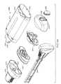
Disclosed are methods and apparatus for treatment of damaged tissue, including treatment of wounds, by employing non-electrically powered reduced pressure therapy devices. Maintenance and control of pressures below the generated atmospheric pressure may be provided by such devices while minimizing user discomfort. In some embodiments, the reduced pressure treatment device comprises a suction device, a sealant layer, a contact matrix, and optional extension tubing. The suction device may be a non-electrically powered device and may be configured to be quiet and / or wearable. In some embodiments, the suction device may have a low profile so that it can be worn inconspicuously under clothing. The sealant layer may create a substantially airtight enclosure on the damaged tissue and provide fluid communication between the suction device and the enclosure containing the damaged tissue. Fluid communication may be provided by a direct connection between the suction device and the sealant layer, or may be provided through an extension tube connecting the suction device and the mounting port. In some embodiments, the sealant layer may be flexible, while in other embodiments, the sealant layer may be semi-rigid or rigid. In some embodiments, the semi-rigid or rigid sealant layer may facilitate processing or application of the sealant layer to the treatment site while reducing or eliminating the risk of folding and adhering to the sealant layer itself. . The extension tubing may be connected to the sealant layer and / or the suction device using a connector or fitting. The connector may optionally include a releasable locking mechanism to facilitate attachment and removal of extension tubing and / or prevent accidental disconnection. For example, the releasable locking mechanism may comprise a release button or other actuator that serves as a locking mechanism that can be manipulated during the installation and / or removal of tubing. In other embodiments, the suction device may be directly connected to the sealant layer attachment port and comprises a connector with the same or similar connector as the extension tubing, for direct attachment of the suction instrument and remote attachment using tubing. Both may be possible.
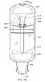
いくつかの実施形態では、治療装置は、減圧を発生させ、任意の吸引される流体または物質を回収するように構成される可変容積チャンバを備える。チャンバは、可変容積チャンバの可動部分に連結される一定力のバネを使用して、作動されてもよい。可変容積チャンバを増加容積に拡張または偏向することによって、可変容積チャンバと、損傷組織を含有してシールされる封入体とによって封入される空気の容積が拡張され、それによって、空気の圧力を減圧してもよい。 In some embodiments, the therapy device comprises a variable volume chamber configured to generate a vacuum and collect any aspirated fluid or material. The chamber may be actuated using a constant force spring coupled to the movable part of the variable volume chamber. By expanding or deflecting the variable volume chamber to an increased volume, the volume of air enclosed by the variable volume chamber and the enclosure that contains and seals the damaged tissue is expanded, thereby reducing the pressure of the air. May be.
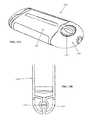
いくつかの実施形態では、減圧治療装置は、非円形吸引チャンバ設計を備え、薄型または小型の治療装置を提供してもよい。いくつかの実施例では、薄型は、延長管類の使用の有無に関わらず、創傷近傍の身体に減圧システムの配置を可能にする。一体型システム構成と連結される本人間工学的チャンバ設計は、装置の分離状態での装着を可能にし、生活の質を向上させてもよい。一特定の実施例では、吸引器具は、楕円形断面幾何学形状を伴う可変容積チャンバを備え、実質的滲出液処理能を提供する一方、また、薄型を提供する。これは、処置の際、可動性、自由裁量、柔軟性、および/または快適性の改善をもたらす。また、薄型幾何学形状は、遠隔部位ではなく、処置部位またはそれに隣接して、吸引器具を配置することによって、減圧治療システム使用のワークフローを能率化してもよく、また、延長管類の使用を排除し、処置部位と別個の吸引器具との間の流体連通を維持してもよい。 In some embodiments, the reduced pressure treatment device may comprise a non-circular suction chamber design to provide a thin or small treatment device. In some embodiments, the low profile allows placement of a vacuum system in the body near the wound, with or without the use of extension tubing. This ergonomic chamber design coupled with an integrated system configuration may allow the device to be detached and improve the quality of life. In one particular embodiment, the suction device comprises a variable volume chamber with an elliptical cross-sectional geometry, providing substantial exudate handling capability while also providing a low profile. This results in improved mobility, discretion, flexibility, and / or comfort during the procedure. The thin geometry may also streamline the workflow of using reduced pressure therapy systems by placing a suction device at or adjacent to the treatment site rather than a remote site, and avoid the use of extension tubing. Eliminating and maintaining fluid communication between the treatment site and a separate suction device.
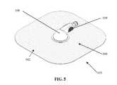
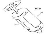
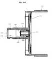
また、シーラント層は、取付けポートを備え、シーラント層への吸引器具または延長管類の取付けおよび/または取外しを促進してもよい。いくつかの実施例では、取付けポートは、シーラント層および吸引器具に対して、種々の相対的構成および/または相対的位置を有してもよい。いくつかの事例では、取付けポートは、連接式および/または可撓性であってもよい。例えば、取付けポートは、旋回台座を伴って構成され、取付けポートの回転を可能にしてもよい。また、連接式および/または可撓性取付けポートは、吸引器具とシーラント層との間を伝達され得る、張力または他の力の伝達を低減してもよい。取付けポートは、製造時に、シーラント層と一体的に形成されてもよく、または別個に提供され、使用時に、シーラント層に取付けられてもよい。後者の実施形態は、シーラント層に対する取付けポートの相対的場所の柔軟性またはカスタマイズを医師に可能にしてもよい。また、取付けポート構成は、取付けポート設計が、吸引器具の移動によって生じ得る、創傷床への張力の連通を最小限にする一方、迅速な一体化を可能にすることによって、患者の快適性の改善をもたらしてもよい。さらに、屈曲および/または回転能力は、取付けポート配向に対するシーラント層の独立配置を可能にする。また、取付けポートの可撓性は、圧点によって誘発される傷害の危険性を低減してもよい。取付けポートは、真空源の単純なスナップ式取付けを可能にしてもよい。創被覆接合面への取付けポートノズルの接続は、小占有面積および/または薄型を有し、圧点傷害の可能性を低減してもよい。いくつかの実施形態では、取付けポートの旋回台座は、シーラント層と一体化される、薄いゴム弾性台座を有してもよい。旋回台座は、最大限のシーラント層の成形性を可能にする一方、より剛性のシステム要素との一体化を維持し、身体表面の周囲にシールを形成するように構成される。いくつかの実施形態では、取付けポートを伴う減圧治療装置は、減圧源をシーラント層に取付け、創傷と減圧源との間に流体連通を生成するために使用される、1つ以上のステップを削減または排除してもよい。既存の減圧治療システムと異なり、取付けポートは、接着剤を伴わずに、および/またはシーラント層を切除せずに、真空源を取付けるように構成されてもよい。 The sealant layer may also include an attachment port to facilitate attachment and / or removal of the suction device or extension tubing to the sealant layer. In some embodiments, the attachment port may have various relative configurations and / or relative positions with respect to the sealant layer and the suction device. In some cases, the attachment port may be articulated and / or flexible. For example, the attachment port may be configured with a swivel pedestal to allow rotation of the attachment port. The articulated and / or flexible attachment port may also reduce the transmission of tension or other forces that may be transmitted between the suction device and the sealant layer. The attachment port may be integrally formed with the sealant layer at the time of manufacture, or may be provided separately and attached to the sealant layer in use. The latter embodiment may allow the physician flexibility or customization of the relative location of the mounting port relative to the sealant layer. The attachment port configuration also allows patient integration by allowing rapid integration while the attachment port design minimizes the communication of tension to the wound bed that may result from movement of the suction device. Improvements may be brought about. Further, the bending and / or rotation capability allows for independent placement of the sealant layer relative to the mounting port orientation. The flexibility of the attachment port may also reduce the risk of injury induced by pressure points. The attachment port may allow a simple snap-on attachment of the vacuum source. The connection of the attachment port nozzle to the wound covering interface may have a small footprint and / or low profile, reducing the possibility of pressure point injury. In some embodiments, the pivoting pedestal of the mounting port may have a thin rubber elastic pedestal that is integrated with the sealant layer. The swivel pedestal is configured to allow for maximum sealant layer formability while maintaining integration with the more rigid system elements and forming a seal around the body surface. In some embodiments, a reduced pressure treatment device with an attachment port attaches a reduced pressure source to the sealant layer, reducing one or more steps used to create fluid communication between the wound and the reduced pressure source. Or you may exclude. Unlike existing reduced pressure treatment systems, the attachment port may be configured to attach a vacuum source without an adhesive and / or without ablating the sealant layer.
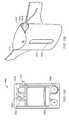
いくつかの実施形態では、減圧治療装置は、1つ以上のアクチュエータを伴って構成され、吸引器具の起動および/または皮膚または組織からの吸引器具の解放を促進してもよい。例えば、吸引器具は、起動機構を備えてもよい。いくつかの実施形態では、吸引器具は、ボタンまたは他のアクチュエータを含有し、処置部位における減圧の印加を始動する。起動機構は、その上または近傍に提供される、「起動」のような言葉または緑色のような色等の標識、あるいは類似意味を伴う任意の他の言葉もしくはコーディングが提供されてもよい。該ボタンの押下によって、弁を開放し、創傷床に隣接して形成される封入体と、吸引チャンバとの間の流体連通を可能にしてもよく、または摺動シールを解除し、移動可能にしてもよい。より具体的には、起動によって、摺動シール下方および創傷封入体内の空間の結合容積を拡張するために、一定力のバネを後退させてもよい。その中に生成される減圧によって、バネと実質的に同等の力を摺動シールに付与してもよい。 In some embodiments, the reduced pressure treatment device may be configured with one or more actuators to facilitate activation of the suction device and / or release of the suction device from the skin or tissue. For example, the suction device may include an activation mechanism. In some embodiments, the suction device contains a button or other actuator to initiate the application of reduced pressure at the treatment site. The activation mechanism may be provided with a word such as “activation” or a label such as a color such as green, or any other word or coding with a similar meaning provided on or near it. Pressing the button may open the valve and allow fluid communication between the enclosure formed adjacent to the wound bed and the suction chamber, or release the sliding seal and allow movement. May be. More specifically, a constant force spring may be retracted to expand the combined volume of the space below the sliding seal and within the wound enclosure upon activation. A force substantially equal to that of the spring may be applied to the sliding seal by the reduced pressure generated therein.
いくつかの実施形態では、減圧治療装置は、弁を閉鎖および/または延長管類または創傷を封入するシーラント層から吸引器具を分断するように構成される、付加的ボタンまたはアクチュエータをさらに備えてもよい。付加的ボタンの押下は、取付けポートまたは延長管類からの吸引器具の取外しを可能にし、一方向弁を起動して、滲出液を吸引チャンバ内に捕捉する、あるいは別様に吸引チャンバからの任意の経路を閉鎖してもよい。 In some embodiments, the reduced pressure treatment device further comprises an additional button or actuator configured to close the valve and / or disconnect the suction device from the sealant layer enclosing the extension tubing or wound. Good. Pressing an additional button allows removal of the suction device from the attachment port or extension tubing, activates a one-way valve to capture exudate in the suction chamber, or alternatively any from the suction chamber The route may be closed.
いくつかの実施形態では、治療装置は、減圧の印加に先立って、装填または装荷されてもよい。装置のいくつかの構成では、装荷および起動方法は、単一の継続ステップで行なわれてもよい。一方、他の構成では、装荷および起動方法は、明確に別個のステップで行なわれてもよい。一実施例では、吸引器具内の摺動シールは、吸引器具の遠位端に位置付けられることによって、装填されてもよい。摺動シールの位置付けは、例えば、スライダまたはプッシュロッド等の種々の装填機構のいずれかによって、行なわれてもよい。いくつかの実施形態では、摺動シールは、装填後、自動的に、後方に摺動を開始し、減圧チャンバ内に圧力差を発生させてもよい。他の実施形態では、吸引器具は、装填機構と別個に作動され、圧力差の発生を始動する、起動機構を備えてもよい。いくつかの構成では、起動機構は、摺動シールの移動を直接阻止または制限してもよい一方、他の構成では、起動機構は、吸引器具のチャンバ内への流体および/または物質の流入を制限または限定してもよい。一実施例では、解放機構は、減圧チャンバに連結される弁を通る連通または流動を変化させるように構成される、別個のボタンまたはレバーを備えてもよい。弁は、例えば、羽根弁または回転可能弁であってもよい。起動ボタンの押下は、羽根弁を持ち上げる、または回転可能弁のレバーを回動し、減圧チャンバ内への流体流動を可能にしてもよい。 In some embodiments, the treatment device may be loaded or loaded prior to application of reduced pressure. In some configurations of the device, the loading and activation method may be performed in a single continuous step. On the other hand, in other configurations, the loading and activation method may be performed in distinctly separate steps. In one example, a sliding seal in the suction device may be loaded by being positioned at the distal end of the suction device. The positioning of the sliding seal may be performed by any of various loading mechanisms such as a slider or a push rod, for example. In some embodiments, the sliding seal may automatically begin sliding backwards after loading to create a pressure differential in the vacuum chamber. In other embodiments, the suction device may include an activation mechanism that is operated separately from the loading mechanism and triggers the generation of a pressure differential. In some configurations, the activation mechanism may directly block or limit the movement of the sliding seal, while in other configurations, the activation mechanism may prevent fluid and / or substance inflow into the chamber of the suction device. It may be limited or limited. In one example, the release mechanism may comprise a separate button or lever configured to change communication or flow through a valve coupled to the vacuum chamber. The valve may be, for example, a vane valve or a rotatable valve. Pressing the activation button may lift the vane valve or rotate the lever of the rotatable valve to allow fluid flow into the vacuum chamber.
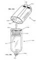
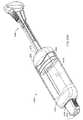
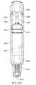
ある実施形態では、装填機構は、力機構を拡張する、または摺動シールをその装填位置に変位させるように構成される、装填キーまたはツールを備える。いくつかの実施例では、装填ツールは、吸引器具の本体の開口部内に位置付けられるように構成される伸長剛性部材を備え、レバーまたはプッシュロッドとして使用され、減圧発生機構を装填してもよい。いくつかの実施形態では、装填ツールを使用して、装填ツールのシャフト内に内蔵されたラッチが定位置に係止されるまで、吸引器具の遠位端に向かって摺動シールを機械的に押圧することができる。いくつかの実施形態では、装填ツールは、吸引器具の本体と一体化され、また、吸引器具を閉鎖するキャップとしての役割を果たしてもよい。いくつかの実施形態では、装填ツールは、吸引器具を非装荷状態に保持および維持するように構成されてもよい。例えば、装填ツールは、吸引器具の本体に解放可能に係止され、非装荷吸引器具の安全な保管を提供してもよく、係止された装填ツールは、保管および/または処理の際、非装荷バネ機構が後退するのを防止あるいは制限する。いくつかの事例では、装填ツールが定位置にない場合、例えば、バネ内に保存されるエネルギーを損失させ得る、吸引チャンバからの微量の漏出のため、保管および/または処理時、後退が生じる場合がある。他の実施形態では、装填ツールは、劣化または別様にある程度装荷が損なわれたバネあるいは他の力機構の再装荷を可能にする。例えば、再装荷は、偶発的放電または非検出漏出によって、バネ内に保存されたエネルギーを損失されると、あるいは回収チャンバが空になると、行なわれてもよい。 In certain embodiments, the loading mechanism comprises a loading key or tool configured to expand the force mechanism or displace the sliding seal to its loading position. In some embodiments, the loading tool comprises an elongate rigid member configured to be positioned within the opening of the body of the suction device and may be used as a lever or push rod to load a reduced pressure generating mechanism. In some embodiments, the loading tool is used to mechanically slide the sliding seal toward the distal end of the suction device until the latch incorporated within the shaft of the loading tool is locked in place. Can be pressed. In some embodiments, the loading tool is integral with the body of the suction device and may serve as a cap to close the suction device. In some embodiments, the loading tool may be configured to hold and maintain the suction device in an unloaded state. For example, the loading tool may be releasably locked to the body of the suction device to provide safe storage of the unloaded suction device, and the locked loading tool may be non-removed during storage and / or processing. Prevent or limit the loading spring mechanism from retracting. In some cases, if the loading tool is not in place, for example, a retraction occurs during storage and / or processing due to a minor leak from the suction chamber that can cause the energy stored in the spring to be lost. There is. In other embodiments, the loading tool allows for reloading of springs or other force mechanisms that have deteriorated or otherwise been partially unloaded. For example, reloading may occur when energy stored in the spring is lost due to accidental discharge or undetected leakage, or when the collection chamber is emptied.
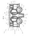
本明細書に提供されるのは、損傷組織を処置するための組織治療装置である。一実施形態では、装置は、シール可能な創傷カバー部と、減圧発生装置とを備える。いくつかの実施形態では、減圧発生装置は、装着式であって、一定範囲の回収容積にわたって、その外寸を実質的に維持するように構成されてもよい。加えて、減圧発生装置は、非円形断面形状を有してもよい。いくつかの実施形態では、減圧発生装置は、非電気的に動力供給されてもよい。そのような実施形態では、減圧発生装置は、弾性部材をさらに備えてもよい。例えば、力部材は、一定力のバネであってもよい。弾性部材が使用される実施形態では、減圧発生装置は、ポテンシャルエネルギーによって、機械的に装荷されるように適合されてもよい。いくつかの実施形態では、減圧発生装置は、実質的に非円筒形形状を備えてもよい。そのような実施形態では、装置は、少なくとも2つの吸引チャンバを備えてもよい。いくつかの事例では、これらの複数の吸引チャンバは、独立して動作してもよい。減圧発生装置が、2つ以上の吸引チャンバを備えるいくつかの実施形態では、装置は、吸引チャンバと別個の少なくとも1つの回収チャンバをさらに備えてもよい。 Provided herein is a tissue therapy device for treating damaged tissue. In one embodiment, the device comprises a sealable wound cover and a reduced pressure generator. In some embodiments, the reduced pressure generator may be wearable and configured to substantially maintain its outer dimensions over a range of collection volumes. In addition, the reduced pressure generator may have a non-circular cross-sectional shape. In some embodiments, the reduced pressure generator may be non-electrically powered. In such an embodiment, the reduced pressure generator may further include an elastic member. For example, the force member may be a constant force spring. In embodiments where a resilient member is used, the reduced pressure generator may be adapted to be mechanically loaded with potential energy. In some embodiments, the reduced pressure generator may comprise a substantially non-cylindrical shape. In such embodiments, the device may comprise at least two suction chambers. In some cases, these multiple suction chambers may operate independently. In some embodiments where the reduced pressure generator comprises two or more suction chambers, the apparatus may further comprise at least one collection chamber that is separate from the suction chamber.
また、本明細書に提供されるのは、患者を処置するための装置である。一実施形態では、装置は、シール可能な創傷カバー部と、非円形減圧発生器具とを備える。いくつかの実施形態では、シール可能な創傷カバー部は、カバーと、カバーと垂直の旋回軸の周囲を旋回するように構成され得る、一体型可撓性取付けポートとをさらに備えてもよい。いくつかの事例では、取付けポートは、シール可能な創傷カバー部から減圧発生器具との流体連通を可能にするように構成されてもよい。いくつかの実施形態では、非円形減圧発生器具は、減圧を発生するように構成され得る、吸引チャンバをさらに備えてもよい。加えて、吸引チャンバは、容積範囲にわたって、一定レベルの減圧を自己維持するようにさらに構成されてもよい。いくつかの実施形態では、減圧発生器具は、一定範囲の回収チャンバ容積にわたって、一定外側構成を維持するように構成されてもよい。いくつかの実施形態では、吸引チャンバの容積は、少なくとも50ccであってもよいが、他の実施形態では、吸引チャンバの容積は、少なくとも100ccであってもよい。本明細書に記載される装置のいくつかのさらなる実施形態では、減圧発生器具は、弾性部材を備えてもよい。そのような実施形態では、減圧発生器具は、弾性部材を機械的に再装荷するように構成されてもよい。いくつかの実施形態では、減圧発生器具は、非電気的に動力供給されてもよい。 Also provided herein is an apparatus for treating a patient. In one embodiment, the device comprises a sealable wound cover and a non-circular vacuum generator. In some embodiments, the sealable wound cover may further comprise a cover and an integral flexible attachment port that may be configured to pivot about a pivot axis perpendicular to the cover. In some instances, the attachment port may be configured to allow fluid communication from the sealable wound cover to the reduced pressure generating device. In some embodiments, the non-circular vacuum generator may further comprise a suction chamber that can be configured to generate a vacuum. In addition, the suction chamber may be further configured to self-maintain a certain level of vacuum over the volume range. In some embodiments, the reduced pressure generating device may be configured to maintain a constant outer configuration over a range of collection chamber volumes. In some embodiments, the suction chamber volume may be at least 50 cc, while in other embodiments the suction chamber volume may be at least 100 cc. In some further embodiments of the devices described herein, the reduced pressure generating device may comprise an elastic member. In such an embodiment, the reduced pressure generating device may be configured to mechanically reload the elastic member. In some embodiments, the reduced pressure generator may be non-electrically powered.
また、本明細書に提供されるのは、患者を処置するための装置である。一実施形態では、装置は、シール可能な創傷カバー部と、非円形減圧発生装置とを備える。いくつかの実施形態では、シール可能な創傷カバー部は、創傷カバー部から創傷封入体を形成するための創傷の周囲のシールへの流体連通を提供するように構成され得る、一体型可撓性取付けポートをさらに備えてもよい。いくつかの実施形態では、取付けポートは、シール可能な創傷カバー部と実質的に平行に旋回するように構成されてもよい。いくつかの実施形態では、非円形減圧発生装置は、弾性部材と、弾性部材をポテンシャルエネルギーによって装荷するように構成される剛性部材とをさらに備えてもよい。そのような実施形態では、弾性部材は、一定力のバネであってもよい。いくつかの実施形態では、減圧発生装置は、非電気的に動力供給されてもよい。加えて、減圧発生装置は、重力に対する減圧発生装置の配向に関係なく、実質的に一定圧力レベルを維持するようにさらに構成されてもよい。いくつかのさらなる実施形態では、減圧発生装置は、減圧発生装置内の吸引または回収された容積に関係なく、固定外寸を維持するように構成されてもよい。 Also provided herein is an apparatus for treating a patient. In one embodiment, the device comprises a sealable wound cover and a non-circular vacuum generator. In some embodiments, the sealable wound cover portion may be configured to provide fluid communication from the wound cover portion to a seal around the wound to form a wound enclosure. An attachment port may be further provided. In some embodiments, the attachment port may be configured to pivot substantially parallel to the sealable wound cover. In some embodiments, the non-circular reduced pressure generator may further comprise an elastic member and a rigid member configured to load the elastic member with potential energy. In such an embodiment, the elastic member may be a constant force spring. In some embodiments, the reduced pressure generator may be non-electrically powered. In addition, the reduced pressure generator may be further configured to maintain a substantially constant pressure level regardless of the orientation of the reduced pressure generator relative to gravity. In some further embodiments, the reduced pressure generator may be configured to maintain a fixed outer dimension regardless of the suctioned or collected volume within the reduced pressure generator.
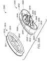
さらに本明細書に提供されるのは、患者を処置するためのシステムである。一実施形態では、本明細書に提供されるシステムは、シール可能な創傷カバー部と、非電気的に動力供給される減圧発生アセンブリとを備える。いくつかの実施形態では、シール可能な創傷カバー部は、シーラント層と、シーラント層を貫通する内腔を伴って構成される可撓性取付けポートとをさらに備えてもよい。いくつかの実施形態では、システムは、少なくとも1つの実質的に一定力の部材をさらに備えてもよい。他の実施形態では、システムは、少なくとも2つの実質的に一定力の部材をさらに備えてもよい。いくつかの事例では、少なくとも1つの力部材は、弾性である。いくつかの実施例では、少なくとも1つの弾性部材は、一定力のバネである。一定力の部材が使用される実施形態では、減圧発生アセンブリは、少なくとも1つの一定力の部材を機械的に装荷するように構成される、伸長剛性部材をさらに備えてもよい。本明細書に記載される減圧発生アセンブリのさらなる実施形態では、減圧発生アセンブリは、移動軸に沿って、吸引チャンバ内を摺動するように構成され得る、シールアセンブリを備える。そのような実施形態では、減圧発生アセンブリは吸引チャンバ内容物に関係なく、移動軸に沿って、固定外寸を維持するように構成されてもよい。加えて、減圧発生アセンブリは、吸引チャンバ内容物に関係なく、固定外側構成を維持するように構成されてもよい。シールアセンブリが使用される実施形態では、シールアセンブリの非平面近位外周は、湾曲非平面近位外周であってもよい。減圧発生アセンブリは、少なくとも1つの可変力部材を備えてもよく、いくつかのさらなる実施例では、少なくとも1つの可変力部材は、シールアセンブリに作用する少なくともある程度の摩擦を相殺するように構成される。さらなる実施例では、減圧発生アセンブリは、実質的に一定力のリボンバネまたは可変力リボンバネであり得る、少なくとも1つのリボンバネを備える。 Further provided herein is a system for treating a patient. In one embodiment, the system provided herein comprises a sealable wound cover and a non-electrically powered reduced pressure generating assembly. In some embodiments, the sealable wound cover may further comprise a sealant layer and a flexible attachment port configured with a lumen extending through the sealant layer. In some embodiments, the system may further comprise at least one substantially constant force member. In other embodiments, the system may further comprise at least two substantially constant force members. In some cases, the at least one force member is elastic. In some embodiments, the at least one elastic member is a constant force spring. In embodiments where a constant force member is used, the reduced pressure generating assembly may further comprise an elongate rigid member configured to mechanically load at least one constant force member. In further embodiments of the reduced pressure generating assembly described herein, the reduced pressure generating assembly comprises a seal assembly that can be configured to slide within the suction chamber along the axis of movement. In such embodiments, the reduced pressure generating assembly may be configured to maintain a fixed outer dimension along the axis of movement regardless of the contents of the suction chamber. In addition, the reduced pressure generating assembly may be configured to maintain a fixed outer configuration regardless of the suction chamber contents. In embodiments where a seal assembly is used, the non-planar proximal perimeter of the seal assembly may be a curved non-planar proximal perimeter. The reduced pressure generating assembly may comprise at least one variable force member, and in some further embodiments, the at least one variable force member is configured to offset at least some friction acting on the seal assembly. . In a further embodiment, the reduced pressure generating assembly comprises at least one ribbon spring, which can be a substantially constant force ribbon spring or a variable force ribbon spring.
システムが減圧発生アセンブリを備える、患者を処置するためのシステムのさらなる実施形態では、減圧発生アセンブリは、第1の寸法と、第1の寸法と垂直の第2の寸法と、第1および第2の寸法と垂直の第3の寸法とを備えてもよい。いくつかの事例では、第1の寸法は、減圧発生アセンブリの最大寸法である。他の事例では、第2の寸法は、第3の寸法よりも大きい。いくつかの実施形態では、第3の寸法は、約5cm以下であってもよいが、他の実施形態では、第3の寸法は、約4cm、約3cm、約2cm、または約1cm以下であってもよい。減圧発生アセンブリが吸引チャンバを備えるいくつかの実施形態では、吸引チャンバは、約500cc以下の容積を有してもよい。他の実施形態では、吸引チャンバは、約250cc以下の容積を有してもよい。さらに他の実施形態では、チャンバは、約100cc以下の容積を有してもよい。いくつかの実施形態では、減圧発生アセンブリは、シール可能な創傷カバー部下の圧力を少なくとも約75mmHg減圧するように構成されてもよい。他の実施形態では、減圧発生アセンブリは、少なくとも約100mmHg圧力を減圧するように構成されてもよい。さらに他の実施形態では、減圧発生アセンブリは、少なくとも約125mmHg圧力を減圧するように構成されてもよい。 In a further embodiment of the system for treating a patient, wherein the system comprises a reduced pressure generating assembly, the reduced pressure generating assembly includes a first dimension, a second dimension perpendicular to the first dimension, and a first and second dimension. And a vertical third dimension. In some cases, the first dimension is the maximum dimension of the reduced pressure generating assembly. In other cases, the second dimension is larger than the third dimension. In some embodiments, the third dimension may be about 5 cm or less, while in other embodiments, the third dimension is about 4 cm, about 3 cm, about 2 cm, or about 1 cm or less. May be. In some embodiments where the vacuum generation assembly comprises a suction chamber, the suction chamber may have a volume of about 500 cc or less. In other embodiments, the suction chamber may have a volume of about 250 cc or less. In still other embodiments, the chamber may have a volume of about 100 cc or less. In some embodiments, the reduced pressure generating assembly may be configured to reduce the pressure under the sealable wound cover by at least about 75 mmHg. In other embodiments, the reduced pressure generating assembly may be configured to reduce at least about 100 mm Hg pressure. In yet other embodiments, the reduced pressure generating assembly may be configured to reduce at least about 125 mmHg pressure.
患者を処置するためのシステムが伸長剛性部材を備えるさらなる実施形態では、そのような伸長剛性部材は、解放可能係止機構を備えてもよい。いくつかの事例では、解放可能係止機構は、ラッチと、ラッチに連結される解放ボタンとを備えてもよい。患者を処置するためのシステムがシールアセンブリを備える実施形態では、シールアセンブリは、少なくとも1つの一定力の部材を押圧するように構成される、少なくとも1つの湾曲表面を備えてもよい。そのような実施形態では、シールアセンブリは、上述の湾曲表面と異なる少なくとも1つの凸面構造をさらに備えてもよい。別の実施形態では、患者を処置するためのシステムは、シール可能な創傷カバー部と、非電気的に動力供給される減圧発生アセンブリとを備えてもよく、減圧発生アセンブリは、弁をさらに備える。いくつかの事例では、弁は、減圧発生アセンブリ内に含有される吸引チャンバとの流体連通を制御するように構成される。いくつかの実施形態では、弁は、回転可能ノブに連結されてもよい。さらに別の実施形態では、患者を処置するためのシステムは、シール可能な創傷カバー部と、減圧発生アセンブリとに連結されるように構成される、コネクタ管をさらに備えてもよい。 In further embodiments where the system for treating a patient comprises an elongate rigid member, such elongate rigid member may comprise a releasable locking mechanism. In some cases, the releasable locking mechanism may comprise a latch and a release button coupled to the latch. In embodiments where the system for treating a patient comprises a seal assembly, the seal assembly may comprise at least one curved surface configured to press at least one constant force member. In such embodiments, the seal assembly may further comprise at least one convex structure that differs from the curved surface described above. In another embodiment, a system for treating a patient may comprise a sealable wound cover and a non-electrically powered reduced pressure generating assembly, the reduced pressure generating assembly further comprising a valve. . In some instances, the valve is configured to control fluid communication with a suction chamber contained within the reduced pressure generating assembly. In some embodiments, the valve may be coupled to a rotatable knob. In yet another embodiment, a system for treating a patient may further comprise a connector tube configured to be coupled to a sealable wound cover and a reduced pressure generating assembly.
さらに本明細書に提供されるのは、患者の処置のためのシステムであって、システムは、減圧発生アセンブリと、シーラント層およびシーラント層を貫通する内腔を伴って構成される可撓性取付けポートをさらに備える、シール可能な創傷カバー部とを備える。いくつかの実施形態では、減圧発生アセンブリは、長手方向軸と、長手方向軸と直角の非円形断面形状と、150cc以下の容積を伴う、取外し可能吸引チャンバを備える。減圧発生アセンブリは、長手方向軸に沿って、吸引チャンバ内を摺動するように構成される、ピストンアセンブリをさらに備えてもよい。いくつかの事例では、ピストンアセンブリは、長手方向軸と直角の非円形断面形状と、非平面近位外周とを有してもよい。減圧発生アセンブリは、ピストンアセンブリに連結され、吸引チャンバ内の圧力を少なくとも約50mmHg減圧するように構成される、少なくとも2つの実質的に一定力のバネコイルをさらに備えてもよい。いくつかの実施形態では、減圧発生アセンブリは、ピストンアセンブリを押動するように構成される、装填ツールをさらに備えてもよい。いくつかの事例では、装填ツールは、係止機構を有してもよい。さらに他の実施形態では、減圧発生アセンブリは、シール可能な創傷カバー部に解放可能に取付けられ、取外し可能減圧チャンバに解放可能に取付けられるように構成される、コネクタ管をさらに備えてもよい。 Further provided herein is a system for treating a patient, the system comprising a reduced pressure generating assembly and a flexible attachment configured with a sealant layer and a lumen extending through the sealant layer. A sealable wound cover, further comprising a port. In some embodiments, the reduced pressure generating assembly comprises a removable suction chamber with a longitudinal axis, a non-circular cross-sectional shape perpendicular to the longitudinal axis, and a volume of 150 cc or less. The reduced pressure generating assembly may further comprise a piston assembly configured to slide within the suction chamber along the longitudinal axis. In some cases, the piston assembly may have a non-circular cross-sectional shape perpendicular to the longitudinal axis and a non-planar proximal perimeter. The reduced pressure generating assembly may further comprise at least two substantially constant force spring coils coupled to the piston assembly and configured to reduce the pressure in the suction chamber by at least about 50 mmHg. In some embodiments, the reduced pressure generating assembly may further comprise a loading tool configured to push the piston assembly. In some cases, the loading tool may have a locking mechanism. In yet other embodiments, the reduced pressure generating assembly may further comprise a connector tube configured to be releasably attached to the sealable wound cover portion and releasably attached to the removable reduced pressure chamber.
別の実施形態では、患者を処置するための方法が提供され、方法は、(a)非電気的に動力供給される非円形減圧発生装置を創傷カバー部から取外すステップと、(b)減圧を発生させずに、減圧発生装置をポテンシャルエネルギーによって装荷するステップと、(c)再装荷された減圧発生装置を創傷カバーに取付けるステップと、(d)再装荷された減圧発生装置を起動し、創傷カバー部下の封入体内に減圧を発生させるステップとを備える。 In another embodiment, a method for treating a patient is provided, the method comprising: (a) removing a non-electrically powered non-circular vacuum generator from the wound cover; and (b) reducing the vacuum. Loading the reduced pressure generator with potential energy without generating, (c) attaching the reloaded reduced pressure generator to the wound cover; (d) activating the reloaded reduced pressure generator; Generating a reduced pressure in the enclosure under the cover.
さらに本明細書に提供されるのは、患者を処置するための方法であって、方法は、(a)創傷カバーを身体部位にシールするステップと、(b)伸長長さと、伸長長さと直角の非円形断面形状とを有する、真空発生装置を使用して、身体部位における圧力レベルを低下させるステップとを備える。いくつかの実施形態では、真空発生装置は、その外寸を変更せずに、身体部位に対するその配向に関係なく、創傷部位において、実質的に一定減圧レベルを維持するように構成されてもよい。そのような実施形態では、方法は、非円形減圧チャンバ内の移動軸に沿って、非円形シールを摺動させるステップをさらに備えてもよく、シールおよび吸引チャンバは、移動軸と直角の非円形構成を有する。
例えば、本発明は以下を提供する。
(項目1)
患者の処置のためのシステムであって、
a.シーラント層と、該シーラント層を貫通する内腔を伴って構成される可撓性取付けポートとを備える、シール可能な創傷カバー部と、
b.i.長手方向軸と、該長手方向軸に直角の非円形断面形状と、150cc以下の容積とを伴う、取外し可能吸引チャンバと、
ii.該長手方向軸に沿って、該吸引チャンバ内を摺動するように構成され、該長手方向軸に直角の非円形断面形状と、非平面近位外周とを有する、ピストンアセンブリと、
iii.該ピストンアセンブリに連結され、該吸引チャンバ内の圧力を少なくとも50mmHg減圧するように構成される、少なくとも2つの実質的に一定力のバネコイルと、
iv.該ピストンアセンブリを押動するように構成され、係止機構を備える、装填ツールと、
v.該シール可能な創傷カバー部に解放可能に取付けられ、該取外し可能吸引チャンバに解放可能に取付けられるように構成される、コネクタ管と
を備える、減圧発生アセンブリと
を備える、システム。
(項目2)
患者の処置のためのシステムであって、
a.シーラント層と、該シーラント層を貫通する内腔を伴って構成される可撓性取付けポートとを備える、シール可能な創傷カバー部と、
b.該取付けポートに連結するように構成され、非円形断面形状を伴う吸引チャンバを備える、非電気的に動力供給される減圧発生アセンブリと
を備える、システム。
(項目3)
前記減圧発生アセンブリは、少なくとも1つの実質的に一定力の部材を備える、項目2に記載のシステム。
(項目4)
前記減圧発生アセンブリは、少なくとも2つの実質的に一定力の部材を備える、項目2に記載のシステム。
(項目5)
前記減圧発生アセンブリは、少なくとも1つの一定力の部材をポテンシャルエネルギーによって機械的に装荷するように構成される、伸長剛性部材を備える、項目3に記載のシステム。
(項目6)
少なくとも1つの力部材は、弾性である、項目3に記載のシステム。
(項目7)
少なくとも1つの弾性の力部材は、一定力のバネである、項目6に記載のシステム。
(項目8)
前記減圧発生アセンブリは、移動軸に沿って、前記吸引チャンバ内を摺動するように構成されるシールアセンブリをさらに備える、項目3に記載のシステム。
(項目9)
前記減圧発生アセンブリは、少なくとも1つのリボンバネを備える、項目2に記載のシステム。
(項目10)
少なくとも1つのリボンバネは、実質的に一定力のリボンバネである、項目9に記載のシステム。
(項目11)
前記減圧発生アセンブリは、少なくとも1つの可変力部材を備える、項目8に記載のシステム。
(項目12)
少なくとも1つの可変力部材は、前記シールアセンブリに作用する少なくともいくらかの摩擦を相殺するように構成される、項目11に記載のシステム。
(項目13)
前記減圧発生アセンブリは、吸引チャンバ内容物に関係なく、前記移動軸に沿って、固定外寸を維持するように構成される、項目8に記載のシステム。
(項目14)
前記減圧発生アセンブリは、吸引チャンバ内容物に関係なく、固定外側構成を有する、項目8に記載のシステム。
(項目15)
前記非平面近位外周は、湾曲非平面近位外周である、項目8に記載のシステム。
(項目16)
前記減圧発生アセンブリは、第1の寸法と、該第1の寸法と垂直の第2の寸法と、該第1および第2の寸法と垂直の第3の寸法とを備え、該第1の寸法は、該減圧発生アセンブリの最大寸法であって、該第3の寸法は、約5cm以下である、項目2に記載のシステム。
(項目17)
前記第2の寸法は、前記第3の寸法よりも大きい、項目16に記載のシステム。
(項目18)
前記第3の寸法は、約4cm以下である、項目16に記載のシステム。
(項目19)
前記第3の寸法は、約3cm以下である、項目16に記載のシステム。
(項目20)
前記第3の寸法は、約2cm以下である、項目16に記載のシステム。
(項目21)
前記第3の寸法は、約1cm以下である、項目16に記載のシステム。
(項目22)
前記吸引チャンバは、約500cc以下の容積を有する、項目16に記載のシステム。(項目23)
前記吸引チャンバは、約250cc以下の容積を有する、項目16に記載のシステム。(項目24)
前記吸引チャンバは、約100cc以下の容積を有する、項目16に記載のシステム。(項目25)
前記減圧発生アセンブリは、少なくとも−75mmHg減圧するように構成される、項目4に記載のシステム。
(項目26)
前記減圧発生アセンブリは、少なくとも−100mmHg減圧するように構成される、項目4に記載のシステム。
(項目27)
前記減圧発生アセンブリは、少なくとも−125mmHg減圧するように構成される、項目4に記載のシステム。
(項目28)
前記伸長剛性部材は、解放可能係止機構を備える、項目5に記載のシステム。
(項目29)
前記解放可能係止機構は、ラッチと、該ラッチに連結される解放ボタンとを備える、項目28に記載のシステム。
(項目30)
前記シールアセンブリは、少なくとも1つの一定力の部材に押圧するように構成される少なくとも1つの湾曲表面を備える、項目8に記載のシステム。
(項目31)
前記シールアセンブリは、前記少なくとも1つの湾曲表面と異なる少なくとも1つの凸面構造を備える、項目30に記載のシステム。
(項目32)
前記吸引力発生アセンブリは、前記吸引チャンバとの流体連通を制御するように構成される弁をさらに備える、項目2に記載のシステム。
(項目33)
前記弁は、回転可能ノブに連結される、項目32に記載のシステム。
(項目34)
前記シール可能な創傷カバー部と、前記吸引力発生アセンブリとに連結されるように構成されるコネクタ管をさらに備える、項目2に記載のシステム。
(項目35)
組織治療装置であって、
a.シール可能な創傷カバー部と、
b.一定範囲の回収容積にわたって、その外寸を実質的に維持するように構成され、非円形断面形状を有する、装着式吸引力発生装置と
を備える、装置。
(項目36)
前記減圧発生装置は、非電気的に動力供給される、項目35に記載の装置。
(項目37)
前記減圧発生装置は、弾性の力部材を備える、項目36に記載の装置。
(項目38)
前記力部材は、一定力のバネである、項目37に記載の装置。
(項目39)
前記減圧発生装置は、ポテンシャルエネルギーによって機械的に装荷されるように適合される、項目38に記載の装置。
(項目40)
前記減圧発生装置は、実質的に非円筒形形状を有する、項目35に記載の装置。
(項目41)
前記減圧発生装置は、少なくとも2つの吸引チャンバを備える、項目36に記載の装置。
(項目42)
前記減圧発生装置は、少なくとも2つの独立吸引チャンバを備える、項目41に記載の装置。
(項目43)
前記減圧発生装置は、前記吸引チャンバから分離した1つの回収チャンバをさらに備える、項目41に記載の装置。
(項目44)
患者の処置のための装置であって、
a.カバーと、該カバーと垂直の旋回軸の周囲を旋回するように構成される一体型可撓性取付けポートとを備える、シール可能な創傷カバー部と、
b.吸引チャンバが、減圧を発生させ、滲出液を回収し、容積範囲にわたって、実質的に一定レベルの減圧を自己維持するように構成される、非円形減圧発生器具と
を備える、装置。
(項目45)
前記容積範囲は、少なくとも50ccである、項目44に記載の装置。
(項目46)
前記容積範囲は、少なくとも100ccである、項目44に記載の装置。
(項目47)
前記減圧発生器具は、弾性の力部材を備える、項目44に記載の装置。
(項目48)
前記減圧発生器具は、前記弾性の力部材を機械的に再装荷するように構成される、項目47に記載の装置。
(項目49)
前記減圧発生ユニットは、非電気的に動力供給される、項目44に記載の装置。
(項目50)
前記取付けポートは、前記シール可能な創傷カバー部と、前記減圧発生器具との間の流体連通を可能にするように構成される、項目44に記載の装置。
(項目51)
前記減圧発生器具は、一定範囲の吸引チャンバ容積にわたって、一定外側構成を維持するように構成される、項目44に記載の装置。
(項目52)
患者の処置のためのシステムであって、
a.シール可能な創傷カバー部であって、該創傷カバー部を通して流体連通を提供し、創傷の周囲をシールして創傷封入体を形成するように構成される一体型可撓性取付けポートを備える、創傷カバー部と、
b.弾性の力部材と、該弾性の力部材をポテンシャルエネルギーによって装荷するように構成される剛性部材とを備える、非円形減圧発生装置と
を備える、システム。
(項目53)
前記取付けポートは、前記シール可能な創傷カバー部と実質的に平行に旋回するように構成される、項目52に記載のシステム。
(項目54)
前記弾性の力部材は、一定力のバネである、項目52に記載のシステム。
(項目55)
前記減圧発生装置は、非電気的に動力供給される、項目52に記載のシステム。
(項目56)
前記減圧発生装置は、重力に対する該減圧発生装置の配向に関係なく、実質的に一定圧力レベルを維持するように構成される、項目54に記載のシステム。
(項目57)
前記減圧発生装置は、該減圧発生装置内の吸引容積に関係なく、固定外寸を維持するように構成される、項目54に記載のシステム。
(項目58)
患者を処置するための方法であって、
a.非電気的に動力供給される非円形減圧発生装置を創傷カバー部から取外すステップと、
b.減圧を発生させずに、該減圧発生装置をポテンシャルエネルギーによって装荷するステップと、
c.該再装荷された減圧発生装置を該創傷カバーに取付けるステップと、
d.該再装荷された減圧発生装置を起動して、該創傷カバー部下の封入体内に減圧を発生させるステップと
を含む、方法
(項目59)
患者を処置するための方法であって、
a.創傷カバーを身体部位に対してシールすることと、
b.伸長長さと、該伸長長さと直角の非円形断面形状とを有する減圧発生装置を使用して、該身体部位における圧力レベルを低減することであって、該減圧発生装置は、その外寸を変更することなく、かつ、該身体部位に対するその配向に関係なく、該創傷部位において、実質的に一定の減圧レベルを実質的に維持するように適合するように構成される、ことと
を含む、方法。
(項目60)
非円形吸引チャンバ内の移動軸に沿って、非円形シールを摺動させることをさらに含み、該シールおよび該吸引チャンバは、該移動軸と直角の非円形構成を有する、項目59に記載の方法。Further provided herein is a method for treating a patient, the method comprising: (a) sealing a wound cover to a body site; (b) an extension length and an angle perpendicular to the extension length. Reducing the pressure level at the body part using a vacuum generator having a non-circular cross-sectional shape. In some embodiments, the vacuum generating device may be configured to maintain a substantially constant reduced pressure level at the wound site without changing its outer dimensions, regardless of its orientation relative to the body site. . In such embodiments, the method may further comprise sliding a non-circular seal along a movement axis in the non-circular vacuum chamber, wherein the seal and suction chamber are non-circular at right angles to the movement axis. It has a configuration.
For example, the present invention provides the following.
(Item 1)
A system for treatment of a patient,
a. A sealable wound cover comprising a sealant layer and a flexible attachment port configured with a lumen extending through the sealant layer;
b. i. A removable suction chamber with a longitudinal axis, a non-circular cross-sectional shape perpendicular to the longitudinal axis, and a volume of 150 cc or less;
ii. A piston assembly configured to slide within the suction chamber along the longitudinal axis and having a non-circular cross-sectional shape perpendicular to the longitudinal axis and a non-planar proximal perimeter;
iii. At least two substantially constant force spring coils coupled to the piston assembly and configured to reduce the pressure in the suction chamber by at least 50 mm Hg;
iv. A loading tool configured to push the piston assembly and comprising a locking mechanism;
v. A reduced pressure generating assembly comprising: a connector tube releasably attached to the sealable wound cover portion and configured to releasably attach to the removable suction chamber.
(Item 2)
A system for treatment of a patient,
a. A sealable wound cover comprising a sealant layer and a flexible attachment port configured with a lumen extending through the sealant layer;
b. A non-electrically powered vacuum generation assembly configured to couple to the attachment port and comprising a suction chamber with a non-circular cross-sectional shape.
(Item 3)
The system of claim 2, wherein the reduced pressure generating assembly comprises at least one substantially constant force member.
(Item 4)
The system of claim 2, wherein the reduced pressure generating assembly comprises at least two substantially constant force members.
(Item 5)
The system of claim 3, wherein the reduced pressure generating assembly comprises an elongate rigid member configured to mechanically load at least one constant force member with potential energy.
(Item 6)
4. The system of item 3, wherein the at least one force member is elastic.
(Item 7)
7. The system of item 6, wherein the at least one elastic force member is a constant force spring.
(Item 8)
4. The system of item 3, wherein the reduced pressure generating assembly further comprises a seal assembly configured to slide within the suction chamber along a movement axis.
(Item 9)
The system of claim 2, wherein the reduced pressure generating assembly comprises at least one ribbon spring.
(Item 10)
10. The system of item 9, wherein the at least one ribbon spring is a substantially constant force ribbon spring.
(Item 11)
The system of claim 8, wherein the reduced pressure generating assembly comprises at least one variable force member.
(Item 12)
12. The system of item 11, wherein the at least one variable force member is configured to cancel at least some friction acting on the seal assembly.
(Item 13)
9. The system of item 8, wherein the reduced pressure generating assembly is configured to maintain a fixed outer dimension along the axis of movement regardless of suction chamber contents.
(Item 14)
9. The system of item 8, wherein the reduced pressure generating assembly has a fixed outer configuration regardless of the suction chamber contents.
(Item 15)
9. The system of item 8, wherein the non-planar proximal perimeter is a curved non-planar proximal perimeter.
(Item 16)
The reduced pressure generating assembly comprises a first dimension, a second dimension perpendicular to the first dimension, and a third dimension perpendicular to the first and second dimensions. The system of claim 2, wherein is the maximum dimension of the reduced pressure generating assembly, and wherein the third dimension is about 5 cm or less.
(Item 17)
The system of item 16, wherein the second dimension is greater than the third dimension.
(Item 18)
17. The system of item 16, wherein the third dimension is about 4 cm or less.
(Item 19)
The system of item 16, wherein the third dimension is about 3 cm or less.
(Item 20)
The system of item 16, wherein the third dimension is about 2 cm or less.
(Item 21)
Item 17. The system of item 16, wherein the third dimension is about 1 cm or less.
(Item 22)
The system of item 16, wherein the suction chamber has a volume of about 500 cc or less. (Item 23)
The system of item 16, wherein the suction chamber has a volume of about 250 cc or less. (Item 24)
The system of item 16, wherein the suction chamber has a volume of about 100 cc or less. (Item 25)
5. The system of item 4, wherein the reduced pressure generating assembly is configured to depressurize at least -75 mmHg.
(Item 26)
5. The system of item 4, wherein the reduced pressure generating assembly is configured to depressurize at least -100 mmHg.
(Item 27)
The system of claim 4, wherein the reduced pressure generating assembly is configured to depressurize at least -125 mmHg.
(Item 28)
6. The system of item 5, wherein the elongate rigid member comprises a releasable locking mechanism.
(Item 29)
29. A system according to item 28, wherein the releasable locking mechanism comprises a latch and a release button coupled to the latch.
(Item 30)
9. The system of item 8, wherein the seal assembly comprises at least one curved surface configured to press against at least one constant force member.
(Item 31)
32. The system of item 30, wherein the seal assembly comprises at least one convex structure that is different from the at least one curved surface.
(Item 32)
The system of claim 2, wherein the suction force generation assembly further comprises a valve configured to control fluid communication with the suction chamber.
(Item 33)
33. A system according to item 32, wherein the valve is coupled to a rotatable knob.
(Item 34)
The system of claim 2, further comprising a connector tube configured to be coupled to the sealable wound cover portion and the suction force generating assembly.
(Item 35)
A tissue treatment device,
a. A sealable wound cover,
b. A wearable suction force generator configured to substantially maintain its outer dimensions over a range of collection volumes and having a non-circular cross-sectional shape.
(Item 36)
36. The apparatus of item 35, wherein the reduced pressure generator is non-electrically powered.
(Item 37)
37. Apparatus according to item 36, wherein the reduced pressure generator comprises an elastic force member.
(Item 38)
38. Apparatus according to item 37, wherein the force member is a constant force spring.
(Item 39)
40. The apparatus of item 38, wherein the reduced pressure generator is adapted to be mechanically loaded with potential energy.
(Item 40)
36. The apparatus of item 35, wherein the reduced pressure generator has a substantially non-cylindrical shape.
(Item 41)
38. Apparatus according to item 36, wherein the reduced pressure generator comprises at least two suction chambers.
(Item 42)
42. Apparatus according to item 41, wherein the reduced pressure generator comprises at least two independent suction chambers.
(Item 43)
42. The apparatus of item 41, wherein the reduced pressure generator further comprises a single collection chamber separated from the suction chamber.
(Item 44)
A device for treatment of a patient,
a. A sealable wound cover portion comprising a cover and an integral flexible attachment port configured to pivot about a pivot axis perpendicular to the cover;
b. A non-circular vacuum generator configured to generate a vacuum, collect exudate, and self-maintain a substantially constant level of vacuum over a volume range.
(Item 45)
45. An apparatus according to item 44, wherein the volume range is at least 50 cc.
(Item 46)
45. Apparatus according to item 44, wherein the volume range is at least 100 cc.
(Item 47)
45. Apparatus according to item 44, wherein the reduced pressure generator comprises an elastic force member.
(Item 48)
48. The apparatus of item 47, wherein the reduced pressure generator is configured to mechanically reload the elastic force member.
(Item 49)
45. The apparatus of item 44, wherein the reduced pressure generating unit is non-electrically powered.
(Item 50)
45. The apparatus of item 44, wherein the attachment port is configured to allow fluid communication between the sealable wound cover and the reduced pressure generating device.
(Item 51)
45. The apparatus of item 44, wherein the reduced pressure generating instrument is configured to maintain a constant outer configuration over a range of suction chamber volumes.
(Item 52)
A system for treatment of a patient,
a. A sealable wound cover comprising an integral flexible attachment port configured to provide fluid communication through the wound cover and seal around the wound to form a wound enclosure. A cover part;
b. A non-circular decompression generator comprising: an elastic force member; and a rigid member configured to load the elastic force member with potential energy.
(Item 53)
53. The system of item 52, wherein the attachment port is configured to pivot substantially parallel to the sealable wound cover portion.
(Item 54)
53. A system according to item 52, wherein the elastic force member is a constant force spring.
(Item 55)
53. The system of item 52, wherein the reduced pressure generator is non-electrically powered.
(Item 56)
55. The system of item 54, wherein the reduced pressure generator is configured to maintain a substantially constant pressure level regardless of the orientation of the reduced pressure generator relative to gravity.
(Item 57)
55. The system of item 54, wherein the reduced pressure generator is configured to maintain a fixed outer dimension regardless of the suction volume within the reduced pressure generator.
(Item 58)
A method for treating a patient, comprising:
a. Removing the non-electrically powered non-circular vacuum generator from the wound cover;
b. Loading the reduced pressure generator with potential energy without generating reduced pressure;
c. Attaching the reloaded vacuum generator to the wound cover;
d. Activating the reloaded reduced pressure generating device to generate a reduced pressure within the enclosure under the wound cover portion (Item 59).
A method for treating a patient, comprising:
a. Sealing the wound cover against the body part;
b. Using a reduced pressure generator having an elongated length and a non-circular cross-sectional shape perpendicular to the elongated length, to reduce the pressure level at the body part, the reduced pressure generator changing its outer dimensions And adapted to substantially maintain a substantially constant reduced pressure level at the wound site without regard to its orientation relative to the body site. .
(Item 60)
60. The method of item 59, further comprising sliding a non-circular seal along a movement axis in the non-circular suction chamber, wherein the seal and the suction chamber have a non-circular configuration perpendicular to the movement axis. .
本明細書に記載される実施形態の種々の特徴および利点のさらなる理解は、例示的実施例を説明する以下の発明を実施するための形態および付随の図面を参照することによって得られるであろう。
(詳細な説明)
実施形態が本明細書に記載および提示されているが、それらの実施形態は、一例として提供されるに過ぎない。本発明から逸脱することなく、変形、変更、および代用が、成されてもよい。本明細書に記載される例示的実施形態の種々の代替が、本発明を実践する際に採用されてもよいことに留意されたい。本明細書に記載される実施形態すべてに対して、方法のステップが、連続的に行なわれる必要はない。(Detailed explanation)
Although embodiments are described and presented herein, these embodiments are provided by way of example only. Variations, changes, and substitutions may be made without departing from the invention. It should be noted that various alternatives to the exemplary embodiments described herein may be employed in practicing the present invention. For all of the embodiments described herein, the steps of the method need not be performed sequentially.
近年、創傷に対して減圧を提供するための技術の最新の適応が、開発されている。これらの種類の減圧創被覆システムのいくつかの市販モデルが存在する。これらの装置は、創傷内に配置される接合面層と、創傷の周囲にシールを生成する閉塞層と、接合面層および創傷と流体連通する接続管類と、別個の滲出液回収吸収缶と、真空源を提供する電気ポンプとを備えてもよい。しかしながら、電気ポンプは、かさばり、かつ重く、それによって、特に、長期的処置期間の際、患者の可動性を低減させる。これらの電気ポンプは、動作時、騒々しく、人目を引く可能性がある。さらに、接合面層、閉塞層、および接続管類の配置は、多大な労働力を要し、時間がかかり、医療従事者への患者の依存性を増加させ、さらに、高額な医療費につながる。これらのシステムは、通常は、非使い捨てポンプおよび系統的構成要素を有し、相当の保守および整備を必要とし、汚染ならびに感染性蔓延の危険性を抱える。これらのシステムは、より小さい創傷を処理するために使用可能であるが、大きい創傷を処置するように設計されており、通常、より小さい創傷を処置するためには使用されない。現在のシステムは、その動作のために、電力に依存するため、電気が利用不可能である場合、さらに、電気を有する領域に患者の移動を制約する、または限定されたバッテリ電力に依存する。 In recent years, the latest adaptations of techniques for providing reduced pressure to wounds have been developed. There are several commercial models of these types of reduced pressure wound coating systems. These devices include an interface layer disposed within the wound, an occlusion layer that creates a seal around the wound, connecting tubing in fluid communication with the interface layer and the wound, and a separate exudate collection absorber. And an electric pump providing a vacuum source. However, electric pumps are bulky and heavy, thereby reducing patient mobility, particularly during long-term treatment periods. These electric pumps can be noisy and eye-catching during operation. In addition, the placement of the interface layer, occlusion layer, and connecting tubing is labor intensive, time consuming, increases the patient's dependence on health care professionals, and leads to high medical costs. . These systems typically have non-disposable pumps and systematic components, require considerable maintenance and service, and carry the risk of contamination and infectious spread. These systems can be used to treat smaller wounds, but are designed to treat larger wounds and are not typically used to treat smaller wounds. Current systems rely on power for their operation, so if electricity is not available, they further constrain patient movement to areas with electricity or rely on limited battery power.
本明細書に記載されるのは、減気圧(すなわち、真空)を損傷組織腔または他の種類の創傷等の処置部位に印加するように構成される装置である。また、いくつかの実施形態では、装置を使用して、別の面では非損傷である組織に減圧を印加してもよい。一実施形態では、組織治療装置は、シーラント層と、吸引器具とを備えてもよい。シーラント層を使用して、治療を要する組織の領域の周囲にシールを生成してもよい。吸引器具は、シーラント層によって形成されるシールされた封入体と流動的に連通し、損傷組織に隣接する封入体内の圧力を減圧する。いくつかの実施形態では、吸引器具は、非電気的に動力供給されてもよい。例えば、吸引器具は、減圧を自己発生させるように、すなわち、別個の電力または真空源を必要とせずに、構成されてもよい。自己発生減圧機構を備える減圧治療装置は、バッテリ電力の消耗を懸念せずに、あるいは電源コンセントまたは真空発生器へのアクセスを有することなく、患者に自由および可動性を提供してもよい。シーラント層および吸引器具を使用して、閉鎖された減圧システムを形成し、システム内への気体の逆流を抑制してもよい。 Described herein is a device configured to apply a reduced pressure (ie, vacuum) to a treatment site, such as a damaged tissue cavity or other type of wound. In some embodiments, the device may also be used to apply reduced pressure to tissue that is otherwise undamaged. In one embodiment, the tissue treatment device may include a sealant layer and a suction device. A sealant layer may be used to create a seal around the area of tissue that requires treatment. The suction device is in fluid communication with the sealed enclosure formed by the sealant layer and reduces the pressure in the enclosure adjacent to the damaged tissue. In some embodiments, the suction device may be non-electrically powered. For example, the suction device may be configured to self-generate a reduced pressure, i.e., without requiring a separate power or vacuum source. A decompression therapy device with a self-generated decompression mechanism may provide freedom and mobility to the patient without worrying about battery power drain or having access to a power outlet or vacuum generator. A sealant layer and a suction device may be used to form a closed vacuum system to inhibit backflow of gas into the system.
減圧は、シールされた封入体と吸引器具との間に共有される、封入体のより小さい容積からより大きい容積へと、シールされた封入体および/または吸引器具内に最初に配置される空気の容積を拡張することによって、自己発生されてもよい。シールされた封入体内の空気の拡張に応じて、空気分子の密度は、減少し、シールされた封入体内の圧力は、大気圧より低い圧力レベルに低下する。 Depressurization is the air initially placed in the sealed enclosure and / or suction device from the smaller volume of the enclosure to the larger volume shared between the sealed enclosure and the suction device. It may be self-generated by expanding its volume. In response to the expansion of air within the sealed enclosure, the density of air molecules decreases and the pressure within the sealed enclosure drops to a pressure level below atmospheric pressure.
一実施形態では、組織治療装置は、創傷床または他の組織欠陥内あるいは上に配置される、接触層基質を備える。いくつかの実施形態では、接触層基質を使用して、創傷床にわたってより均等に減圧を分配してもよく、また、足場または接触表面を提供し、治癒を促進してもよい。次いで、別の実施形態では、接触層基質によって充填される損傷組織腔は、シーラント層下に配置され、接触層および創傷床を含有するシールされた封入体を生成する。封入体の内部への流体連通は、シーラント層の取付けポートによって提供される。 In one embodiment, the tissue treatment device comprises a contact layer substrate disposed within or on the wound bed or other tissue defect. In some embodiments, a contact layer matrix may be used to distribute the vacuum more evenly across the wound bed and may provide a scaffold or contact surface to promote healing. In another embodiment, the damaged tissue cavity filled with the contact layer matrix is then placed under the sealant layer to produce a sealed enclosure containing the contact layer and the wound bed. Fluid communication to the interior of the enclosure is provided by a sealant layer mounting port.
いくつかの実施形態では、取付けポートは、入口開口部と、軟性ゴム弾性体と、出口ポートとを伴う、環を備えてもよい。いくつかの実施例では、環は、剛性または可撓性物質を備えてもよく、環は、垂直角度を含む、シーラント層に対する種々の角度のいずれかで配向されてもよい。また、取付けポートの出口ポートは、可撓性または剛性であってもよく、シーラント層あるいは環に対して、種々の角度のいずれかで配向されてもよい。いくつかの実施例では、出口ポートは、概して、環の高さに応じて、シーラント層の面に平行に、またはシーラント層の平行面よりさらに下に配向されてもよいが、他の実施例では、出口ポートは、シーラント層の面より上に屈曲あるいは角度付けられてもよい。取付けポートの種々の構成要素は、互いに直接接続されてもよく、またはそうでなくてもよく、入口および出口は、互いに対してある程度の移動自由度を有してもよい。 In some embodiments, the attachment port may comprise an annulus with an inlet opening, a soft rubber elastomer, and an outlet port. In some examples, the ring may comprise a rigid or flexible material and the ring may be oriented at any of a variety of angles relative to the sealant layer, including a vertical angle. Also, the outlet port of the attachment port may be flexible or rigid and may be oriented at any of a variety of angles with respect to the sealant layer or ring. In some embodiments, the exit port may generally be oriented parallel to the plane of the sealant layer or even below the parallel plane of the sealant layer, depending on the height of the ring, although other embodiments Then, the exit port may be bent or angled above the surface of the sealant layer. The various components of the attachment port may or may not be directly connected to each other and the inlet and outlet may have some degree of freedom of movement relative to each other.
装置のいくつかの実施形態では、装置は、親水コロイド物質または当業者に周知の任意の他の物質から成る、シーラント層を備えてもよい。親水コロイドシーラント層は、半多孔性および通気性であって、創傷から湿気を吸収する一方、皮膚を保護してもよい。加えて、親水コロイドシーラント層は、通常は、アクリル接着剤等の他の物質よりも厚く、折り重なりおよびしわ寄りを抑え、より容易な配置を可能にし、潜在的流体漏出路をシールする。 In some embodiments of the device, the device may comprise a sealant layer consisting of a hydrocolloid material or any other material known to those skilled in the art. The hydrocolloid sealant layer is semiporous and breathable and may absorb moisture from the wound while protecting the skin. In addition, the hydrocolloid sealant layer is typically thicker than other materials such as acrylic adhesives, suppresses folding and wrinkling, allows easier placement, and seals potential fluid leak paths.
本明細書に開示される装置の一実施形態では、取付けポートは、吸引器具の遠位部分に直接搭載される。他の実施形態では、取付けポートは、延長管を介して、吸引器具に接続される。いくつかの実施形態では、延長管は、絡み合いを軽減するように適合されてもよい。吸引器具および延長管類は、類似継手ならびに解放ボタンを有し、偶発的切断を防止してもよい。延長管類が使用される実施形態では、延長管類の遠位端は、類似継手によって、吸引器具の遠位端に接続される。 In one embodiment of the device disclosed herein, the attachment port is mounted directly on the distal portion of the suction device. In other embodiments, the attachment port is connected to the suction device via an extension tube. In some embodiments, the extension tube may be adapted to reduce entanglement. The suction device and extension tubing may have similar joints and release buttons to prevent accidental disconnection. In embodiments where extension tubing is used, the distal end of the extension tubing is connected to the distal end of the suction device by a similar joint.
本明細書に開示される装置のいくつかの実施形態は、取付けポートまたは別の構成要素に一体化される、圧力計を備える。取付けポート内への圧力計の搭載は、創傷に隣接し、シーラント層によって形成される、封入体内の圧力レベルの正確な測定を可能にする。本明細書に記載される圧力計は、通常は、減圧源を創傷に接続する管類内の凝塊によって生じる、不正確な圧力示度の影響を受けにくくしてもよい。 Some embodiments of the devices disclosed herein comprise a pressure gauge that is integrated into a mounting port or another component. The mounting of a pressure gauge within the attachment port allows for an accurate measurement of the pressure level within the inclusion, adjacent to the wound and formed by the sealant layer. The pressure gauges described herein may be less susceptible to inaccurate pressure readings that are typically caused by clots in the tubing that connect the vacuum source to the wound.
本明細書に開示される減圧システムのいくつかの実施形態では、吸引器具は、減圧発生ユニットの外寸を変更せずに、封入体内の空気の容積を強制的に拡張することによって、損傷組織に隣接する封入体内の空気圧を減圧する。他の実施形態では、組織治療装置は、実質的に一定レベルに圧力を自己調整してもよい。 In some embodiments of the reduced pressure system disclosed herein, the suction device may cause damaged tissue by forcibly expanding the volume of air within the enclosure without changing the outer dimensions of the reduced pressure generating unit. The air pressure in the enclosure adjacent to is reduced. In other embodiments, the tissue treatment device may self-adjust the pressure to a substantially constant level.
一実施形態では、吸引器具は、チャンバと、摺動シールと、弁と、起動システムとを備える。吸引カートリッジは、遠位部分に解放ボタンおよび起動ボタンを備えてもよい。起動ボタンは、摺動羽根弁に接続され、「オフ」位置にある時、創傷に隣接する封入領域からチャンバへの流体連通を防止してもよい。起動ボタンが押下されると、摺動羽根弁は、「オン」位置に切り替わり、封入体からチャンバへの流体連通を可能にしてもよい。起動ボタンは、「オフ」位置に偏向されるようにバネ荷重されてもよいが、押下されると、バネ荷重ラッチは、「オン」位置に留まるように係合してもよい。解放ボタンは、吸引器具からの任意の物品(例えば、延長管類またはシーラント層取付けポート)の取外しを可能にし、吸引チャンバと封入領域との間の流体連通を終了させるように適合および構成されてもよい。解放ボタンは、相互係止セグメントに係合し、ラッチを起動ボタンから引き離してもよい。起動ボタンが「オン」位置にある場合、バネ荷重によって、「オフ」位置に復帰するであろう。 In one embodiment, the suction device comprises a chamber, a sliding seal, a valve, and an activation system. The suction cartridge may include a release button and an activation button on the distal portion. The activation button may be connected to the sliding vane valve to prevent fluid communication from the containment area adjacent to the wound to the chamber when in the “off” position. When the activation button is pressed, the sliding vane valve may switch to the “on” position to allow fluid communication from the enclosure to the chamber. The activation button may be spring loaded to be deflected to the “off” position, but when depressed, the spring loaded latch may engage to remain in the “on” position. The release button is adapted and configured to allow removal of any article (eg, extension tubing or sealant layer attachment port) from the suction device and to terminate fluid communication between the suction chamber and the containment region. Also good. The release button may engage the interlocking segment and pull the latch away from the activation button. If the activation button is in the “on” position, the spring load will return to the “off” position.
減圧システムの一実施形態では、吸引チャンバは、その中に同心円状に配置される摺動シールを有する、楕円シリンダを備える。チャンバは、摺動羽根弁に接続される開口部に隣接して位置するチャンバの遠位端と、摺動シールの現在の位置との間の距離によって画定される可変有効容積を有する。装填状態では、シールは、吸引カートリッジの遠位端に最近接し、チャンバの有効容積は、ゼロまたはほぼゼロである。摺動シールは、1つまたは一連のバネに接続され、チャンバの有効容積が最大である起動状態に向かって、シールを偏向するために使用されてもよい。バネは、リボンバネを含む、種々の構成のいずれかを有してもよい。リボンバネは、実質的に一定力のバネまたは可変力のバネであってもよい。いくつかの実施例では、バネの種類を組み合わせて使用されてもよい。さらに他の実施例では、単一リボンが、両端にコイルを伴って構成され、単一リボンの中央領域において、摺動可能シールに取付けられてもよい。装置の一実施形態では、バネは、0.5ポンド未満の力を付与してもよい。本発明の他の実施形態では、一定力のバネは、1ポンド未満の力を付与してもよい。減圧システムのいくつかの実施形態では、一定力のバネは、5ポンド未満の力を付与してもよい。本明細書に開示される装置の他の実施形態では、実質的に一定力のバネは、20ポンド未満の力を付与してもよい。他の実施例では、装置の回収容積にわたって付与される毎平方インチ当たりの力は、約0.1psi乃至約50psi、いくつかの実施例では、約0.5乃至約20psi、他の実施例では、約1.5psi乃至約5psiの範囲であってもよい。本圧力は、単一力部材によって付与されてもよく、または2つ以上の力部材からの総圧力であってもよい。力または圧力は、処置される創傷の種類、サイズ、場所、あるいは別の好適な特徴に基づいて、選択されてもよい。 In one embodiment of the vacuum system, the suction chamber comprises an elliptical cylinder having a sliding seal disposed concentrically therein. The chamber has a variable effective volume defined by the distance between the distal end of the chamber located adjacent to the opening connected to the sliding blade valve and the current position of the sliding seal. In the loaded state, the seal is closest to the distal end of the suction cartridge and the effective volume of the chamber is zero or nearly zero. A sliding seal may be connected to one or a series of springs and used to deflect the seal towards an activation state where the effective volume of the chamber is maximal. The spring may have any of a variety of configurations, including a ribbon spring. The ribbon spring may be a substantially constant force spring or a variable force spring. In some embodiments, a combination of spring types may be used. In yet another embodiment, a single ribbon may be configured with coils at both ends and attached to a slidable seal in the central region of the single ribbon. In one embodiment of the device, the spring may apply a force of less than 0.5 pounds. In other embodiments of the present invention, the constant force spring may apply less than one pound of force. In some embodiments of the reduced pressure system, the constant force spring may apply a force of less than 5 pounds. In other embodiments of the devices disclosed herein, the substantially constant force spring may apply a force of less than 20 pounds. In other embodiments, the force per square inch applied across the recovery volume of the device is about 0.1 psi to about 50 psi, in some embodiments, about 0.5 to about 20 psi, in other embodiments May range from about 1.5 psi to about 5 psi. This pressure may be applied by a single force member or may be the total pressure from two or more force members. The force or pressure may be selected based on the type, size, location, or other suitable characteristics of the wound being treated.
組織治療システムのいくつかの実施形態では、吸引カートリッジは、減圧下、吸引チャンバ形状の外側形状を維持するように適合される、剛性ポリマーから製造される。吸引チャンバは、ポリカーボネート、コポリエステル、ポリエチレン、ポリプロピレン、アクリル、ABS、ガラス、医療等級ポリマー、またはそれらの組み合わせ等の任意の好適なポリマーから成ることができるが、それらに限定されない。 In some embodiments of the tissue treatment system, the suction cartridge is manufactured from a rigid polymer that is adapted to maintain the outer shape of the suction chamber shape under reduced pressure. The suction chamber can be made of any suitable polymer such as, but not limited to, polycarbonate, copolyester, polyethylene, polypropylene, acrylic, ABS, glass, medical grade polymer, or combinations thereof.
減圧システムの他の実施形態では、摺動シールは、その下方の吸引器具の一部と吸引器具の残部との間の気密性分離を生成するように適合される、物質から製造される。物質は、ゴム弾性または非ゴム弾性であってもよい。摺動シールは、シリコーン、フルオロシリコーン、ニトリル、天然ゴム、熱可塑性エラストマー、熱可塑性ウレタン、ブチル、ポリオレフィン、ポリウレタン、スチレン、ポリテトラフルオロエチレン、任意の他の好適な物質、またはそれらの組み合わせ等の物質から成ることができる。 In another embodiment of the vacuum system, the sliding seal is made from a material that is adapted to create an airtight separation between a portion of the suction device below it and the remainder of the suction device. The material may be rubber elastic or non-rubber elastic. The sliding seal can be silicone, fluorosilicone, nitrile, natural rubber, thermoplastic elastomer, thermoplastic urethane, butyl, polyolefin, polyurethane, styrene, polytetrafluoroethylene, any other suitable material, or combinations thereof Can consist of a substance.
組織治療システムのいくつかの実施形態では、吸引カートリッジは、摩擦軽減潤滑剤を使用してコーティングされ、吸引チャンバ内の摩擦による摺動シールの移動を低減し、長期間静止位置に存在後、シールが粘着する可能性を低下させてもよい。潤滑コーティング物質は、ポリジメチルシロキサン、ペルフルオロポリエーテル、ミネラルスピリット、合成油、ポリキシレン、任意の他の好適な潤滑ポリマーまたは物質、あるいは任意のそれらの組み合わせであってもよい。 In some embodiments of the tissue treatment system, the suction cartridge is coated using a friction reducing lubricant to reduce the sliding seal movement due to friction in the suction chamber, and after being in a stationary position for an extended period of time, the seal The possibility of sticking may be reduced. The lubricating coating material may be polydimethylsiloxane, perfluoropolyether, mineral spirit, synthetic oil, polyxylene, any other suitable lubricating polymer or material, or any combination thereof.
本明細書に開示される減圧システムの一実施形態では、吸引器具バネは、起動に先立って、高ポテンシャルエネルギー拡張状態に配置される。装置の他の実施形態では、起動に先立って、摺動羽根弁は、閉鎖され、チャンバは、完全にシールされる。そのような実施形態では、チャンバ内の極端に小容積の空気でも、摺動シールの一定力のバネの後退によって生じるであろう拡張を阻止するため、バネが後退しないように防止される。装置は、創傷床がシーラント層によってシールされると、起動の準備が整い、シーラント層は、直接または延長管を介して、吸引カートリッジに接続される。 In one embodiment of the reduced pressure system disclosed herein, the suction device spring is placed in a high potential energy expanded state prior to activation. In other embodiments of the device, prior to activation, the sliding vane valve is closed and the chamber is completely sealed. In such an embodiment, even an extremely small volume of air in the chamber prevents the spring from retreating to prevent expansion that would otherwise be caused by the constant force spring retraction of the sliding seal. The device is ready for activation once the wound bed is sealed by the sealant layer, which is connected to the suction cartridge either directly or via an extension tube.
本明細書に開示される組織治療システムが起動されると、流体連通が、吸引チャンバとシールされた創傷封入体との間に確立される。封入体内には、有限量の空気(最初は、大気圧)が存在するため、起動に応じて、一定力のバネが、摺動シールを後退させ、吸引チャンバの有効容積を拡張するであろう。理想気体の法則によって知られるように、空気の容積が断熱的に拡張するのに伴って、空気の圧力は、低下し、シールされた創傷封入体を減圧に曝すであろう。 When the tissue treatment system disclosed herein is activated, fluid communication is established between the suction chamber and the sealed wound enclosure. Due to the presence of a finite amount of air (initially atmospheric pressure) within the enclosure, a constant force spring will retract the sliding seal and expand the effective volume of the suction chamber upon activation. . As is known by the ideal gas law, as the volume of air expands adiabatically, the pressure of the air will drop and subject the sealed wound enclosure to reduced pressure.
いくつかの実施形態では、組織治療システムを使用して、システム内へ漏出される滲出液および空気の存在に関わらず、実質的に一定レベルの減圧を維持してもよい。摺動シールは、機械的システムであって、シール位置は、実質的に一定力のバネの牽引力、システム内の他の牽引力要素、および/またはチャンバシールにわたる圧力差に基づいて、均衡であるように適合および構成される。システム内の他の牽引力要素は、摩擦力(すなわち、静的および/または動的摩擦力)を含んでもよい。減圧をチャンバ内で大気圧に戻す場合、バネの引張力は、圧力差による引張力よりも大きくなるであろう。これは、言い換えると、バネを後退させ、チャンバの容積を同時に増加させるであろう。本容積増加は、新しい均衡状態が到達され、圧力差および実質的に一定のバネ力が新しい均衡状態に到達するまで、チャンバ内において、大気圧からの圧力低下をもたらすであろう。いくつかの実施形態では、吸引チャンバの壁は、直線であって、それによって、チャンバ内のシールの実際の位置に関わらず、減圧のレベルが一定に留まることを保証する。 In some embodiments, a tissue treatment system may be used to maintain a substantially constant level of vacuum regardless of the presence of exudate and air leaking into the system. A sliding seal is a mechanical system where the seal position appears to be balanced based on a substantially constant spring traction force, other traction elements in the system, and / or a pressure differential across the chamber seal. Fit and configured. Other tractive force elements in the system may include frictional forces (ie, static and / or dynamic frictional forces). If the vacuum is returned to atmospheric pressure in the chamber, the spring tension will be greater than the tension due to the pressure differential. This, in other words, will retract the spring and increase the volume of the chamber at the same time. This increase in volume will result in a pressure drop from atmospheric pressure in the chamber until a new equilibrium is reached and the pressure differential and a substantially constant spring force reach the new equilibrium. In some embodiments, the walls of the suction chamber are straight, thereby ensuring that the level of vacuum remains constant regardless of the actual position of the seal within the chamber.
いくつかの実施形態では、吸引器具は、概して、絶対圧力レベルおよび/または大気圧に対する圧力レベルの低下によって特徴付けられ得る、減圧を発生させるように構成されてもよい。いくつかの実施形態では、装置は、約0乃至約760mmHgの減圧レベルを発生させるように構成される。いくつかの実施形態では、シーラント層および処置部位によって形成される封入体内で発生される減圧の量は、約10mmHg、約20mmHg、約50mmHg、約80mmHg、約100mmHg、約150mmHg、約200mmHg、約500mmHg、約700mmHg、または約750mmHg以上である。装置は、シーラント層下で絶対減圧を発生させてもよく、減圧は、約0乃至約760mmHgのいずれかの値である。いくつかの実施形態では、シーラント層によって形成される封入体内で発生される減圧のレベルは、約700mmHg未満、ある時には、約600mmHg、またある時には、約400mmHg未満、またはさらに約250mmHg未満、約125mmHg、約75mmHg、約50mmHg、約25mmHg、あるいは約10mmHg未満である。いくつかの実施形態では、シーラント層は、概して、処置される組織の領域の外周に追従する。組織治療装置は、異なる回収チャンバサイズを有し、より大きく、より滲出性の創傷の処理を可能にする一方、使用快適性を向上させるための最小構成の可能性を維持してもよい。これは、より小さい減圧源が、創被覆またはシーラント層に部分的または完全に一体化可能であるため、小創傷または処置部位に特に有利である場合がある。いくつかの実施形態では、吸引器具の空洞は、容積約50cc以下である一方、他の実施形態では、空洞は、容積約100ccであってもよい。他の実施形態では、回収チャンバは、容積約150cc未満である。いくつかの実施形態では、回収チャンバは、容積約200cc未満である。他の実施形態では、回収チャンバは、容積約300ccより小さい。いくつかの実施形態では、回収チャンバは、容積約500cc未満である。他の実施形態では、回収チャンバは、容積約1000cc未満である。他の実施形態では、吸引器具の空洞は、少なくとも約50cc、約100cc、約150cc、約200cc、約300cc、約500cc、または約1000cc以上であってもよい。 In some embodiments, the suction device may be configured to generate a reduced pressure that may be generally characterized by a decrease in pressure level relative to absolute pressure level and / or atmospheric pressure. In some embodiments, the device is configured to generate a reduced pressure level of about 0 to about 760 mmHg. In some embodiments, the amount of reduced pressure generated within the enclosure formed by the sealant layer and the treatment site is about 10 mmHg, about 20 mmHg, about 50 mmHg, about 80 mmHg, about 100 mmHg, about 150 mmHg, about 200 mmHg, about 500 mmHg. , About 700 mmHg, or about 750 mmHg or more. The apparatus may generate an absolute vacuum under the sealant layer, the vacuum being anywhere from about 0 to about 760 mmHg. In some embodiments, the level of reduced pressure generated within the enclosure formed by the sealant layer is less than about 700 mmHg, sometimes about 600 mmHg, and sometimes less than about 400 mmHg, or even less than about 250 mmHg, about 125 mmHg. , About 75 mmHg, about 50 mmHg, about 25 mmHg, or less than about 10 mmHg. In some embodiments, the sealant layer generally follows the perimeter of the area of tissue being treated. The tissue treatment device may have different collection chamber sizes, allowing for the treatment of larger, more exudative wounds while maintaining the possibility of minimal configuration to improve comfort in use. This may be particularly advantageous for small wounds or treatment sites because a smaller vacuum source can be partially or fully integrated into the wound covering or sealant layer. In some embodiments, the suction device cavity has a volume of about 50 cc or less, while in other embodiments, the cavity may have a volume of about 100 cc. In other embodiments, the collection chamber is less than about 150 cc in volume. In some embodiments, the collection chamber is less than about 200 cc in volume. In other embodiments, the collection chamber is less than about 300 cc in volume. In some embodiments, the collection chamber is less than about 500 cc in volume. In other embodiments, the collection chamber is less than about 1000 cc in volume. In other embodiments, the suction device cavity may be at least about 50 cc, about 100 cc, about 150 cc, about 200 cc, about 300 cc, about 500 cc, or about 1000 cc or more.
ある実施形態では、装置は、吸引器具の近位端である開口部内に嵌入し、レバー内に内蔵されるラッチが定位置に係止されるまで、装置の遠位端に向かってバネを押下することによって、一定力のバネをポテンシャルエネルギーによって装荷するレバーとしての役割を果たす、伸長剛性部材を備える。いくつかの実施形態では、伸長部材は、吸引器具本体に一体化され、吸引器具のキャップとしての役割を果たす。いくつかの実施形態では、伸長レバーは、バネ内に保存されるエネルギーを損失させ得る、微量の漏出によるバネの後退を防止するため、吸引器具の安全な保管を可能にする。他の実施形態では、偶発的放電が生じると、または装置の使用時、非検出漏出が存在すると、バネ機構の再装荷を可能にする。 In certain embodiments, the device fits into the opening that is the proximal end of the suction device and pushes the spring toward the distal end of the device until the latch incorporated in the lever is locked in place. Thus, an elongate rigid member serving as a lever for loading a spring having a constant force with potential energy is provided. In some embodiments, the elongate member is integrated into the suction device body and serves as a cap for the suction device. In some embodiments, the extension lever allows for safe storage of the suction device to prevent the spring from retracting due to a small amount of leakage that can cause the energy stored in the spring to be lost. In other embodiments, the spring mechanism may be reloaded when an accidental discharge occurs or when there is an undetected leak when the device is in use.
いくつかの実施形態では、吸引器具は、吸引力発生ユニットの近位端の嵌合開口部内に挿入されるように適合および構成される、伸長剛性部材を備える。伸長剛性部材は、チャンバシールの剛性部分に接触し、したがって、一定力のバネに対して、チャンバの下方にシールを機械的に押動するために使用され、それによって、ポテンシャルエネルギーを一定力のバネに与えることができる。本押動運動は、吸引カートリッジが延長管類または取付けポートから分離され、起動ボタンおよび摺動羽根弁がオフ位置に来ることによって完了する。摺動シールが最大バネ延長近接点に到達すると、伸長剛性部材上のラッチタブは、吸引器具本体内のスロットに係合し、バネの後退を防止するであろう。本時点では、摺動羽根弁は、解放ボタンを押下することによって閉鎖され、それによって、チャンバをシールするはずである。次いで、伸長部材は、起動の準備のために吸引器具を残して、ラッチタブを押下することによって除去することができる。 In some embodiments, the suction device comprises an elongate rigid member adapted and configured to be inserted into a mating opening at the proximal end of the suction force generating unit. The elongate rigid member contacts the rigid portion of the chamber seal and is therefore used to mechanically push the seal down the chamber against a constant force spring, thereby reducing the potential energy to a constant force. Can be given to the spring. This pushing motion is completed when the suction cartridge is separated from the extension tubing or mounting port and the activation button and the sliding vane valve are in the off position. When the sliding seal reaches the maximum spring extension proximity point, the latch tab on the elongate rigid member will engage a slot in the suction device body and prevent spring retraction. At this point, the sliding vane valve should be closed by depressing the release button, thereby sealing the chamber. The elongate member can then be removed by depressing the latch tab leaving the suction device in preparation for activation.
図1は、吸引器具101と、延長管102と、シーラント層103とを備える、減圧治療装置100の一実施形態を例示する。シーラント層103は、シーラント層103を延長管102および/または直接吸引器具101に接続するように構成される、一体型取付けポート106をさらに備えてもよい。いくつかの実施形態では、延長管102または吸引器具101のコネクタは、取付けポート106の軸を中心として回転するように構成されてもよい。いくつかの実施形態では、取付けポート106は、その台座110の周囲を回転する、ならびに/あるいはシーラント層103に向かっておよび/またはそこから離れて屈曲するように構成されてもよい。例えば、取付けポート106は、約360度以上自由に回転する、あるいは約360度未満、例えば、約315度、約270度、約225度、約180度、約135度、約90度、または約45度を含むが、それらに限定されない、制限された回転範囲を提供するように構成されてもよい。他の実施形態では、管類コネクタおよび/または取付け部のコネクタ接合面は、長手方向内腔軸に対して回転するように構成されてもよい。取付けポート106は、概して、シーラント層の面に平行な固定配向を有してもよいが、他の構成では、平行面より下方または上方に角度付けられてもよい。さらに他の実施例では、取付けポート106は、シーラント層103に対して、屈曲または旋回するように構成されてもよい。屈曲または旋回範囲は、約0度乃至約45度または約90度、約0度乃至135度または約180度、あるいは約−15度または約−30度乃至約45度、約90度、約135度、約180度、195度、もしくは約210度であってもよい。ある実施形態では、取付けポート106は、回転および旋回するように構成されてもよい。 FIG. 1 illustrates one embodiment of a reduced
延長管は、種々の機構のいずれかによって、取付けポートに連結されてもよい。例えば、取付けポートは、延長管の内腔内に挿入され得る、抵抗または干渉継手を備えてもよい。抵抗継手は、延長管の分断を阻止するように構成される、1つ以上のフランジを備えてもよい。他の実施例では、延長管は、取付けポートの内腔または開口部内に挿入されてもよく、取付けポートは、John Guest継手(Middlesex、UK)等の押し込み継手を備えてもよい。他の実施形態では、螺設または機械的相互係止継手を含む、両構成要素上のコネクタが使用されてもよい。コネクタは、構成要素の連結および分断の両方を促進するように構成されてもよい。 The extension tube may be coupled to the attachment port by any of a variety of mechanisms. For example, the attachment port may comprise a resistance or interference coupling that can be inserted into the lumen of the extension tube. The resistance joint may comprise one or more flanges configured to prevent the extension tube from breaking. In other examples, the extension tube may be inserted into the lumen or opening of the attachment port, and the attachment port may comprise a push-in fitting such as a John Guest fitting (Middlesex, UK). In other embodiments, connectors on both components may be used, including threaded or mechanical interlock joints. The connector may be configured to facilitate both connection and disconnection of the components.
図1に描写される実施例では、延長管102の一端は、取付けポートのコネクタ接合面111に連結されるように構成される、ポートコネクタ105を備え、他端は、吸引器具101のコネクタ接合面113に連結するように構成される、吸引器具コネクタ107を備えてもよい。描写される実施形態では、取付けポート106のコネクタ接合面111および延長管102の吸引器具コネクタ107は、オス型コネクタを備えてもよい一方、吸引器具101のコネクタ接合面113および延長管102のポートコネクタ105は、メス型コネクタを備えてもよい。上述の特定のオス・メス構成は、例示に過ぎず、他の実施形態では、オス・メス構成が反転されてもよく、非指向性であって、任意の方向における延長管102のコネクタを可能にする接合面を含む、任意の他の種類の相補的接合面が使用されてもよい。これらまたは他の相補的構成を使用して、吸引器具101とシーラント層103との直接接続と、延長管102の任意の使用の両方を可能にしてもよい。いくつかの実施形態では、延長管および/または延長管コネクタは、また、複数の延長管が、指定の順番または任意の順番において、ともに結合され得るように構成されてもよい。また、延長管は、例えば、管の挟着または他の変形を阻止し得る、螺旋巻線または他の管状支持部等の1つ以上の応力除去または耐捻転構造を備えてもよい。図1では、例えば、延長管102のポートコネクタ105および吸引器具コネクタ107は、それぞれ、張り出し開口部115および117を備え、コネクタ105および107に対して、少なくともある程度の管102のたわみを可能にする一方、張り出し開口部115および117の長さに沿って、屈曲応力を分配し、挟着を阻止する。他の実施形態では、コネクタの応力除去構造は、1つ以上の屈曲可能または変形可能突起(張り出していてもよく、またはそうでなくてもよい)を備えてもよい。 In the embodiment depicted in FIG. 1, one end of the
また、延長管の1つ以上のコネクタは、係止機構を備え、延長管の分断および/または取付けを促進してもよい。いくつかの実施例では、係止機構は、シーラント層および/または吸引器具からの不慮の分断を阻止してもよい。図1に描写される実施例では、延長管102のポートコネクタ105は、ボタン108が押下されるまで、分断を阻止するように構成されるコネクタ解放ボタン108を伴う、係止機構を備える。コネクタ解放ボタン108は、取付けポート106上の相補的構造または表面と相互係止あるいは抵抗嵌合を形成する、可動構造に連結されてもよい。いくつかの実施形態では、コネクタ解放ボタン108は、バネ荷重または別様に偏向されてもよく、コネクタ105と取付けポート106との間に付加的シールおよび/または係止力を提供してもよく、またはそうでなくてもよい。他の変形例では、スライダ、レバー、またはノブを含む、他の係止接合面が使用されてもよい。取付けポート106は、1つ以上の把持物質または加工把持表面109を備えてもよい。取付けポート106の外側の把持表面109は、延長管102または吸引器具101上のコネクタの手動接続および切断を促進してもよい。把持表面109は、例えば、1つ以上のフランジあるいは隆起部、および/またはポリスチレンならびにポリブタジエン樹脂を伴う、ゴムもしくはブロックコポリマー、例えば、Kraton Polymers, LLC(Houston、Texas)から市販のKRATON(登録商標)ポリマー等の高牽引力物質を備えてもよい。また、把持物質または構造は、コネクタ105ならびに107および/または吸引器具101上に提供されてもよい。図1では、例えば、吸引器具101は、吸引器具101の本体121に対して縮小幅を有する、前端部品104を備える。前端部品104は、延長管102または取付けポート106から取外したりあるいは引き離す際、吸引器具101の把持を促進してもよい。 Also, one or more connectors of the extension tube may include a locking mechanism to facilitate splitting and / or attachment of the extension tube. In some embodiments, the locking mechanism may prevent inadvertent disconnection from the sealant layer and / or the suction device. In the embodiment depicted in FIG. 1, the
いくつかの実施形態では、吸引器具は、概して、減圧下、その形状を維持するように構成される、剛性ポリマーを備えてもよい。吸引器具は、ポリカーボネート、コポリエステル、ポリエチレン、ポリプロピレン、アクリル、ABS、ガラス、または当業者に周知の任意の他のポリマー等の任意の好適なポリマーから成ることができる。 In some embodiments, the suction device may comprise a rigid polymer that is generally configured to maintain its shape under reduced pressure. The suction device can be made of any suitable polymer, such as polycarbonate, copolyester, polyethylene, polypropylene, acrylic, ABS, glass, or any other polymer known to those skilled in the art.
図2および3は、図1の吸引器具101の一実施形態の詳細図である。コネクタ接合面113は、図1に描写されるように、延長管102の近位端において、コネクタ107に、および/または取付けポート106のコネクタ接合面111に連結され得る、コネクタ200を備えてもよい。吸引器具101は、吸引チャンバ202内に配置される、摺動シール207をさらに備えてもよい。図2は、吸引チャンバ202の遠位端208の近傍の遠位位置にある摺動シール207を描写し、図3は、吸引チャンバ202の近位端209の近傍の近位位置にある摺動シール207を描写する。摺動シール207は、シール搭載部210上に搭載され、チャンバ202の遠位端208と近位端209との間を横断するように構成される一方、実質的気密性シールを維持してもよい。また、吸引チャンバ202は、シール207によって分離されるチャンバ202の一部によって特徴付けられてもよい。例えば、吸引チャンバ202は、チャンバ202の遠位端208とシール207との間に配置される回収チャンバ216と、吸引チャンバ202の近位端209とシール207との間の作業チャンバ218とを備えてもよい。回収チャンバ216は、減圧を発生するように構成され、コネクタ200と流体連通し、シーラント層103下に減圧を提供してもよい。図2および3に描写される特定の実施形態では、創傷から吸引される物質の回収および減圧の発生の両方が、回収チャンバ216内で生じるが、他の実施形態では、回収チャンバおよび減圧発生チャンバは、異なる構造であってもよい。 2 and 3 are detailed views of one embodiment of the
吸引器具101の作業チャンバ218は、1つ以上の力または偏向部材を含有してもよく、また、シール207へのアクセスを提供し、力または偏向部材の装填あるいは装荷を可能にしてもよい。力または偏向部材の一部は、作業チャンバ218の一部に取付けあるいは固定されてもよい一方、別の部分は、シール207に取付けられる。図2に描写される特定の実施形態では、力部材は、2つの一定力のバネ212を備え、近位端215は、支柱またはピン213を使用して、作業チャンバ218内に搭載される一方、その遠位端217は、シール207に連結されるシール搭載部210に取付けられる。いくつかの実施形態では、シール207およびシール搭載部210は、一体的に形成されてもよい。摺動シール207は、注入外側被覆、接着剤接合、あるいは機械的接合等の方法によって、もしくは機械的抵抗または相互係止嵌合によって、シール搭載部210上に搭載されてもよい。他の実施形態では、力部材は、シール207に直接連結されてもよい。シール207の機能および構造は、以下に詳述される。 The working
回収チャンバ216および作業チャンバ218の容積は、シール207の位置に応じて、変動してもよい。図2では、シール207が、拡張位置および装填構成にあり、回収チャンバ216の有効容積は、約ゼロまたはゼロに近くてもよい。図3では、シール207が、後退位置にあり、回収チャンバ216の有効容積は、シール207、シール搭載部210、および/または偏向部材によって占有される容積に関わらず、吸引チャンバ202の容積またはほぼ吸引チャンバ202の容積であってもよい。他の実施例では、回収チャンバの容積は、概して、偏向部材によって発生される力と、回収チャンバ216内に発生される減圧から生じる反作用力との均衡に基づいてもよい。作業チャンバ218の容積は、回収チャンバ216の容積に逆相関してもよい。いくつかの事例では、作業チャンバ218の最大容積は、シール207あるいはシール搭載部210による、および/または作業チャンバ218もしくは作業チャンバ218の移動範囲を限定する構造内に配置される他の構造による容積変位から生じ得る、吸引チャンバ202の容積未満であってもよい。 The volumes of the
シール207へのアクセスは、筐体220の遠位端209を中心として配置される、アクセス開口部224を通して達成されてもよい。摺動シール207が、図2に描写されるような拡張位置から、図3に描写されるような後退位置へと横行するのに伴って、回収チャンバ216の内部容積は、約ゼロから、完全後退位置で提供される約最大容積へと増加し、吸引器具101は、最大有効回収容積を伴う、回収チャンバ216を備える。回収チャンバ216が、シールされた創傷封入体との気密性流体連通状態にあり、良好な創被覆シールが、創傷封入体内で得られると、回収チャンバ216の容積の拡張は、シールされた創傷封入体内の圧力レベルを、一定力のバネ212によって摺動シール207に印加される復元力と、摺動シール207にわたる圧力差との間の均衡が到達される点まで低減させるであろう。 Access to the
吸引器具101のいくつかの実施形態は、コネクタ200と回収チャンバ216との間の流体連通を選択的に可能にするように構成され得る、弁201をさらに備えてもよい。弁201は、例えば、回転シリンダ弁または羽根弁を含む、種々の構成のいずれかを有してもよい。また、弁は、多方向弁、二方向弁、または一方向弁であってもよい。弁201の構成は、起動ボタン203または他の種類のアクチュエータ(例えば、ノブ、スイッチ、レバー、またはスライダ)によって、制御されてもよい。いくつかの実施形態では、起動ボタン203は、チャンバ弁201が、回収チャンバ216とコネクタ200との間の流体連通を閉鎖または遮断する、第1の構成と、弁201が、空気および/または滲出液の通過を開放あるいは可能にし、コネクタから回収チャンバ216へ流動させる、第2の位置とを備えてもよい。いくつかのさらなる実施形態では、いくつかの弁は、吸引器具101および/またはシーラント層内への物質の注入を選択的に可能にする付加的構成、ならびに/あるいは回収チャンバから空気および/または物質の除去を選択的に可能にする構成を有してもよい。 Some embodiments of the
さらなる実施形態では、バネ機構204は、弁201またはそのアクチュエータを閉鎖あるいは開放位置へと偏向してもよい。例えば、バネ機構204は、弁201を閉鎖位置へと偏向し、コネクタ200と回収チャンバ216との間の流体連通を遮断するように構成されてもよい。弁201が作動され、流体連通を開放する際、ラッチ機構205または他の種類の係止機構を使用して、弁201に係合し、バネ機構204が弁201を閉鎖するのを防止してもよい。また、係止機構は、延長管またはシーラント層の選択的切断あるいは分離を可能にするように構成される、解放機構を備えてもよい。例えば、コネクタ200は、解放ボタン206または他のアクチュエータが押下あるいは操作されるまで、コネクタ200を通して吸引器具101に接続される、任意の構成要素の切断を防止もしくは阻止するように構成されてもよい。解放機構は、例えば、1つ以上の交換可能、または可動抵抗、あるいは相互係止構造を備えてもよい。他の実施形態では、係止および/または解放機構は、延長管あるいはシーラント層の取付けポート上に配置されてもよい。 In further embodiments, the
いくつかの実施形態では、解放ボタン206は、弁201を制御するための機構を備えてもよい。例えば、解放ボタン206は、ラッチ205を弁201から係脱させ、バネ機構204に、コネクタ200と回収チャンバ216との間の流体連通を遮断する閉鎖位置へと弁201を再位置付け可能にするように構成されてもよい。他の実施形態では、解放ボタン206は、流体連通経路内の第2の弁を制御するように構成されてもよい。 In some embodiments, the
いくつかの実施形態では、吸引器具101は、シール207の移動軸に横断または垂直の面に対して非円形断面形状を伴う、吸引チャンバ202を備えてもよい。非円形断面形状は、例えば、ほぼ矩形またはほぼ楕円形状を含むが、それらに限定されなくてもよい。吸引器具101は、第2の横寸法より大きい第1の横寸法を備えてもよく、各横寸法は、摺動シール407の移動軸と直角である。いくつかの実施形態では、第1の横寸法と第2の横寸法との比率は、少なくとも約1.5、ある場合には、少なくとも約2、またある場合には、少なくとも約3、または約5以上である。 In some embodiments, the
シールされた創傷封入体内で減圧レベルを発生させるための吸引器具101を準備するために、装置が、装填される、すなわち、摺動シール207および実質的に一定力のバネ212が、吸引チャンバ202内の遠位または拡張位置に配置されてもよい。吸引器具101の装填は、シール207またはシール搭載部210へのアクセスを提供するように構成される開口部224を通して挿入される、押動機構あるいはツールを使用して行なわれてもよい。図4に描写される装填ツール400を含む、押動機構の実施例は、以下に詳述される。図2に戻ると、摺動シール207は、拡張位置に配置され、また、一定力のバネ212は、拡張状態にあり、ポテンシャルエネルギーによって装荷されている。いくつかの実施形態では、吸引器具101が装填されると、羽根弁201が閉鎖され、回収チャンバ216をシールする。これらの実施形態では、回収チャンバ216内の小容積の空気が、一定力のバネ212の後退によって生じるであろう拡張を阻止するため、一定力のバネ212によるシール207の後退は、阻止または防止される。吸引器具101は、係止機構を備え、摺動シール207を装填位置に維持してもよい。また、いくつかの実施形態では、装填機構またはツールを使用して、摺動シール207を定位置に維持し、一定力のバネ212による後退を阻止してもよい。 In order to prepare the
創傷床がシーラント層によってシールされ、装填された治療装置が吸引器具に接続されると、装填された治療装置が起動され、創傷床内に減圧を発生させてもよい。いくつかの実施形態では、本明細書に記載される治療装置のユーザは、起動ボタン203を押下することによって、治療装置を起動してもよい。いくつかの実施例では、起動に先立って、起動ボタン203が、「オフ」位置に偏向されてもよい。起動ボタンを押下または別様に操作することによって、弁201に、回収チャンバ216とシールされた封入体との間の流体連通を開放させる。起動ボタン203が押下されると、相互係止部品上のバネ荷重ラッチは、起動ボタン203を「オン」位置に維持するように係合してもよい。 When the wound bed is sealed by the sealant layer and the loaded treatment device is connected to the suction device, the loaded treatment device may be activated to generate a vacuum within the wound bed. In some embodiments, a user of the treatment device described herein may activate the treatment device by pressing the
減圧治療装置が起動されると、流体連通が、シールされた創傷封入体と回収チャンバ216との間に確立される。十分な創被覆シールが、シールされた封入体内に得られる場合、初めは大気圧であるシールされた封入体内に、有限量の空気および/または滲出液が存在するはずである。次いで、吸引器具101の起動に応じて、装荷された一定力のバネ212は、摺動シール207を後退させ、回収チャンバの容積216を拡張させるであろう。摺動シール207の移動は、一定力のバネ212の牽引力が摺動シール207にわたる圧力差と等しくなる均衡位置で停止するであろう。 When the reduced pressure treatment device is activated, fluid communication is established between the sealed wound enclosure and the
回収チャンバが、シールされた創傷封入体あるいはシステム内の他の場所内への潜在的空気の漏出による滲出液および/または空気によって充填されるのに伴って、摺動シール207は、図3に描写されるように、一定力のバネ212が後退位置に到達するまで、吸引チャンバ202の近位端209に向かって後退するであろう。さらなる後退は、吸引チャンバ202内の制限構造(該当する場合)によって、または減圧回収チャンバ216が、創傷封入体および回収チャンバ216によって共有される結合容積内の増加による大気圧に戻るのに伴う、対抗力の減少の結果として、停止されてもよい。次いで、治療装置は、処置部位から除去されてもよく、または吸引器具101は、シーラント層103から切断されてもよい。上述のように、切断は、解放ボタン206を押下または作動させることによって、達成されてもよい。解放ボタン206が押下または作動されると、羽根チャンバ弁201は、その「オフ」位置に係合され、シールされた創傷封入体と回収チャンバ216との間の任意の流体連通を終了あるいは遮断するであろう。また、起動ボタン203を「オン」位置に強制または維持する、相互係止部品上のバネ荷重ラッチ205は、引き離される、または別様に操作され、起動ボタン203をその「オフ」位置へと戻すであろう。 As the collection chamber is filled with exudate and / or air due to leakage of potential air into the sealed wound enclosure or elsewhere in the system, the sliding
図4に描写されるように、組織治療システムのいくつかの実施形態は、吸引器具101内に挿入され得る、装填ツールまたはロッド400を備えてもよい。ロッド400は、筐体220の開口部224を通して押動され、摺動シールを吸引チャンバ202の遠位端208に向かって押動し、一定力のバネをポテンシャルエネルギーによって装荷させてもよい。いくつかの実施形態では、吸引器具101は、装填ツール400が、一定力のバネ212がシール搭載部210に連結される場所またはそこに隣接して、シール搭載部(図2の210)に接触あるいは係合するように構成されてもよい。他の実施形態では、吸引器具101は、装填ツール400が、シール搭載部210の押圧に加え、またはその代わりに、バネ212を直接押圧するように構成されてもよい。いくつかの実施形態では、摺動シールが装填構成に移動されると、装填ツール400のシャフト403上に配置される係止構造またはラッチ402は、筐体220の相補的構造(例えば、図3のスロット219)に係合してもよい。したがって、装填ツール400を使用して、その装填構成にシールを係止し、一定力のバネが後退し、そのポテンシャルエネルギーを損失するのを阻止してもよい。また、装填ツール400は、ハンドル412を備え、ツール400の把持および使用を促進してもよい。 As depicted in FIG. 4, some embodiments of the tissue treatment system may comprise a loading tool or
他の実施例では、装填機構は、装填ツールを装置から除去せずに、使用されてもよい。これらの実施形態では、シールが後退するのに伴って、装填ツールは、筐体のアクセス開口部から延出するであろう。さらに他の実施例では、実質的に一定力のバネまたは他の偏向部材を解き放ちおよび延出させ、装置を装填するために使用され得る、1つ以上の回転可能ノブを含むが、それに限定されない、線形の押動型機構以外の装填機構が使用されてもよい。いくつかの他の実施例では、バネおよび装填装置に対抗するために必要とされる力が過度であってもよく、装填ツールは、螺設され、装填ツール開口部は、ハンドルに連結されるネジ駆動部を伴って構成され、装置を装填するユーザに機械的利点を提供してもよい。さらに他の実施例では、回転可能ノブを備える実施形態は、摺動式ハンドル、揺動式ハンドル、または取付け可能ハンドルを備え、ユーザがノブを回すと、より大きなトルクを提供してもよい。 In other embodiments, the loading mechanism may be used without removing the loading tool from the device. In these embodiments, as the seal is retracted, the loading tool will extend from the access opening in the housing. Still other embodiments include, but are not limited to, one or more rotatable knobs that can be used to unload and extend a substantially constant force spring or other deflecting member and load the device. A loading mechanism other than a linear push mechanism may also be used. In some other embodiments, the force required to counter the spring and loading device may be excessive, the loading tool is threaded, and the loading tool opening is coupled to the handle It may be configured with a screw drive and provide mechanical advantages to the user loading the device. In yet another example, an embodiment comprising a rotatable knob may comprise a sliding handle, a rocking handle, or an attachable handle, and may provide greater torque when the user turns the knob.
図2および3に戻ると、アクセス開口部224は、挿入の際、装填ツール400の旋回または角形成を制限または限定するように構成されてもよい。また、筐体220は、ガイド222を備え、挿入の際、装填ツール400の運動をさらに制限または限定してもよい。また、装填ツール400は、ガイド構造を備えてもよい。図4は、例えば、バネ212が拡張されるのに伴って、一定力のバネ212に沿ったシャフト403の追跡を促進し得る隆起部または隆起縁410を伴う、装填ツール400を描写する。装填ツール400および/またはシール搭載部210の遠位端は、相補的接合面を伴って構成され、装填ツール400を使用して力が印加されているため、分断を阻止してもよい。 Returning to FIGS. 2 and 3, the access opening 224 may be configured to limit or limit swiveling or angulation of the
いくつかの実施形態では、上述の装填手順は、吸引器具が、任意の他の構成要素、例えば、延長管類、取付けポート、またはシーラント層から切断されると、行なわれてもよい。吸引器具装填後、吸引器具は、直接または延長管類を通して、シーラント層に取付けられ、装填ツールが除去され、吸引器具上の起動ボタンが押下され、シーラント層によって生成される、シールされた創傷封入体内に減圧を印加する。他の実施形態では、本装填プロセスは、「オフ」位置にある起動ボタンによって完遂される。そのような設計は、上昇圧が不注意に損傷組織に印加されるのを防止してもよい。また、回収チャンバと連通する一方向弁が提供され、装填手順の際、回収チャンバから空気を排出してもよい。依然として、図3および4を参照すると、いくつかの実施形態では、吸引器具101が装填されると、装填ツール400のシャフト403上のラッチタブ404または他のアクチュエータが、押下あるいは操作され、ラッチ402を相互係止スロット215から係脱することができ、それによって、装填ツール400を吸引器具101から抜脱可能となる。いくつかの実施形態では、微量の漏出によって一定力のバネが後退するのを防止するため、装填ツール400が吸引器具内に残され、吸引器具の安全な保管を保証してもよい。いくつかの実施例では、装填手順は、製造時に行なわれてもよい一方、他の実施例では、吸引器具は、非装填状態で提供され、使用時に装填されてもよい。 In some embodiments, the loading procedure described above may be performed when the suction device is cut from any other component, such as an extension tubing, attachment port, or sealant layer. After the suction device is loaded, the suction device is attached to the sealant layer, either directly or through extension tubing, the loading tool is removed, the activation button on the suction device is pressed, and the sealed wound is created by the sealant layer Apply reduced pressure to the body. In other embodiments, the loading process is completed by an activation button in the “off” position. Such a design may prevent inadvertent pressure from being inadvertently applied to damaged tissue. A one-way valve in communication with the collection chamber may also be provided to exhaust air from the collection chamber during the loading procedure. Still referring to FIGS. 3 and 4, in some embodiments, when the
いくつかの実施形態では、シール搭載部210は、安定化装置211をさらに備え、吸引器具101の主要軸に対する摺動シール207の過度の角度変位を防止または阻止してもよい。安定化装置211は、シール搭載部210からの長手方向延長部または突起を備えてもよい。安定化装置211は、概して、シール207の長手方向移動軸に平行な配向を有してよく、またはそうでなくてもよい。また、安定化装置211は、その全長に沿って、吸引チャンバ202の壁と摺動接触するように構成されてもよく、または吸引チャンバ202の壁と部分的にのみ接触するように構成されてもよい。例えば、安定化装置の一部は、吸引チャンバの壁から湾曲または角度付けられてもよい。いくつかの実施形態では、吸引器具101の内部は、摩擦軽減潤滑剤または潤滑剤コーティングをさらに備える。他の実施例では、シールおよび/またはシール搭載部は、その外周に沿って可変厚を有する、または吸引チャンバの壁と接触してもよい。いくつかの事例では、増加厚によって、シールの寸法に沿って、シールの安定性を増加させてもよい。いくつかの実施例では、増加厚を伴うシールおよび/またはシール搭載部の一部は、a)外周の一部、およびb)シールおよび/またはシール搭載部の中心移動軸を交差する横寸法に応じて、変動してもよい。可変厚を伴うシールおよび/またはシール搭載部の他の実施例は、以下に詳述される。 In some embodiments, the
図5は、取付けられる延長管を伴わない、図1のシーラント層103を描写する。シーラント層103の主要体500は、損傷組織区分または創傷に対して円周方向に皮膚に接着することによって、処置される組織の一部上に気密性シールを形成するように構成される、実質的に平坦の可撓性物質を備えてもよい。いくつかの実施形態では、シーラント層103の裏面は、種々のシリコーンPSAのいずれかを含むが、それらに限定されない、感圧接着剤(PSA)層502を備える。シーラント層103の主要体500は、0.001乃至0.5インチ厚の平均的厚さを備えてもよく、しわ寄りまたは不慮の折り重なりを阻止するための十分な厚さを備えてもよく、またはそうでなくてもよい。上述のように、取付けポート106は、シーラント層103の表面に近接する面に垂直の軸を中心として旋回するように構成されてもよい。いくつかの実施形態では、旋回範囲は、限定されてもよいが、他の実施形態では、取付けポート106は、360度以上旋回可能である。いくつかの実施形態では、取付けポート106は、把持表面をさらに備え、取付けポート106の適切な継手に対する接続および分離を促進する。 FIG. 5 depicts the
図6は、シーラント層103の断面図を描写する。本実施形態では、取付けポート106は、取付けポート106内の導管601と流体連通する、シーラント層103の主要体500内に開窓または開口部600をさらに備える。いくつかの実施形態では、シーラント層103は、シーラント層103の主要体500に接着または取付けられる、固定旋回継手台座602をさらに備える。取付けポート106は、気密状態において、旋回継手台座602と嵌合し、旋回継手台座602を中心として取付けポート106を回転させる、旋回継手環603をさらに備える。取付けポート106は、コネクタ604をさらに備え、延長管類または吸引器具等の他の構成要素との気密性接続を促進してもよい。いくつかの実施形態では、取付けポート106のコネクタ604および/または旋回継手環603は、可撓性ゴム弾性体605に連結されてもよい。導管601は、旋回継手環603、ゴム弾性体605の中空区分、およびコネクタ604を貫通する。いくつかの実施形態では、旋回継手環603およびコネクタ604は、剛性物質を備えてもよいが、可撓性ゴム弾性体605は、環603とコネクタ604との間の相対的移動を可能にする。いくつかの実施例では、ある程度の屈曲を可能にする一方、挟着を阻止するように構成され得る、可撓性体605は、1つ以上の導管支持構造を備え、導管601の閉塞をもたらし得る可撓性体の挟着を阻止する。 FIG. 6 depicts a cross-sectional view of the
いくつかの実施形態では、装置は、下肢創傷の処置のために使用されてもよい。吸引器具は、患者の皮膚または身体に対する配置に関して、薄型の状態で構成されてもよく、例えば、吸引器具は、より小さい表面と垂直の第1の外寸を有し、通常のズボンの脚部下の脚または腿上におけるその配置を促進し、その薄型は、非円形吸引チャンバ設計を通して達成され、器具の外形を薄くする一方、吸引チャンバが大量の滲出液を取り扱うことを可能にする。装置のいくつかの実施形態では、ユーザの肢または胴、あるいはベルトもしくは他の衣類物品に装置を取付けるように構成される、取付け機構を備える。装置のいくつかの実施形態では、取付け機構は、調節可能自己把持締結具を伴う、布製脚部細片である。布製脚部細片は、綿または発泡体、あるいは当業者に周知の任意の他の物質から構築されることができる。装置の他の実施形態では、取付け機構は、吸引器具を含有し、身体に取付けられるように適合される、可撓性ポケットである。 In some embodiments, the device may be used for the treatment of lower limb wounds. The suction device may be configured in a thin state with respect to placement on the patient's skin or body, for example, the suction device has a first outer dimension perpendicular to a smaller surface and below the leg of a normal trouser Its thinness is achieved through a non-circular suction chamber design, which reduces the profile of the instrument while allowing the suction chamber to handle large amounts of exudate. Some embodiments of the device comprise an attachment mechanism configured to attach the device to a user's limb or torso, or belt or other clothing article. In some embodiments of the device, the attachment mechanism is a fabric leg strip with adjustable self-gripping fasteners. The fabric leg strips can be constructed from cotton or foam, or any other material known to those skilled in the art. In other embodiments of the device, the attachment mechanism is a flexible pocket that contains a suction device and is adapted to be attached to the body.
上述のように、減圧治療装置は、延長管と併用されてもよく、いくつかの実施例では、延長管は、サイズがカスタマイズされてもよい。延長管102の所望の長さは、延長管を使用して、吸引器具配置場所までの距離を査定することによって、決定されてもよい。図7に例示されるように、延長管102は、切断前に、最初に、シーラント層103に取付けられてもよいが、他の実施例では、延長管102は、切断時、シーラント層および/または吸引器具に取付けられる、あるいは取付けられなくてもよい。また、シーラント層および吸引器具は、延長管長を査定する際、処置部位または配置場所に適用されてもよく、あるいはそうでなくてもよい。延長管の所望の長さが決定されると、延長管102が切断され、近位管類断片を除去してもよい。図8Aから8Cに示されるように、延長管102は、コネクタ802を使用して、吸引器具101に接続されてもよい。コネクタ802の第1の端部803は、延長管の裸端部に結合または挿入するために構成されてもよく、いくつかの実施例では、1つ以上の先細構造810、フランジ812、および/または返しを備え、結合を促進する、ならびに/あるいは分断を阻止してもよい。コネクタ802の第2の端部804は、吸引器具101の相補的コネクタ805に接続するように構成されてもよい。他の実施形態では、コネクタは必要とされず、延長管の裸端部または切断端部は、吸引器具101に直接連結されてもよい。さらに他の実施例では、延長管の両端は、コネクタと事前に取付けられ、延長管の中央区分が、切除されてもよく、2つの残留区分は、両端が裸管類に取付けられるように構成されるコネクタを使用して、ともに結合されることができる。 As described above, the reduced pressure treatment device may be used in conjunction with an extension tube, and in some embodiments, the extension tube may be customized in size. The desired length of the
図1から4に描写される減圧治療装置は、別個の「起動」および「解放」アクチュエータを伴う吸引器具101を備えるが、他の実施形態では、「起動」および「解放」位置を伴う単一アクチュエータが、提供されてもよい。さらに他の実施形態では、アクチュエータが提供されなくてもよい。後者の実施形態のいくつかでは、吸引器具は、装填ツールからの力が印加されなくなると、開始され、減圧を発生させてもよい。他の実施例では、吸引器具は、延長管の結合または分断によって、弁を開閉し得る、起動および/または解放機構を伴って構成されてもよい。例えば、吸引器具は、延長管またはコネクタがそこに挿入されると開放する、スリット弁を備えてもよい。 The reduced pressure therapy device depicted in FIGS. 1-4 comprises a
図9Aから9Dは、装填ツール902を伴う、減圧治療装置900の別の実施形態を例示する。図9Aおよび9Bは、2つの位置(それぞれ、装填位置および起動位置)に係合される、装填ツール902を描写する。最初に、減圧治療装置900を装填するために、ユーザは、装置900の本体906の開口部905内に装填ツール902を挿入および押入してもよい。装填ツール900が、摺動シールのシール搭載部に接触するのに伴って、摺動シールは、装置900の遠位端908に向かって変位され、シール搭載部に取付けられる一定力のバネを拡張し、したがって、ポテンシャルエネルギーをバネに与える。いくつかの実施例では、装置900の開口部905および/または本体906は、シールまたはシール搭載部へのツール902の接触あるいは係合を促進するように構成される。例えば、開口部908は、ツール902のシャフト910に対して相補的断面形状を伴って構成されてもよく、および/または装置900の本体906は、ツール902の平行移動あるいは角度変位が低減されるように、開口部905と連通する通路を伴って構成されてもよい。また、いくつかの実施例では、ツールは、内部バネの縁および/または表面に沿って追跡し、シールあるいはシール搭載部への接触もしくは係合を促進するように構成されてもよい。例えば、ツール902のシャフト910は、1つ以上の突出縁914を伴って構成されてもよい。縁914は、内部バネの縁に沿って追跡するように構成されてもよい。ツール902の遠位端は、シールあるいはシール搭載部上の構造に対して相補的構造を伴って構成され、ユーザおよび/またはバネによって力が付与されるため、ツール902との間の分断の危険性を低減してもよい。 FIGS. 9A-9D illustrate another embodiment of a reduced
図9Aでは、装填ツール902は、装置900の近位端905から遠位端908に向かって、摺動シール(図示せず)を押動する。また、装置900および装填ツール902は、ツール902および/または摺動シールをその装填位置に解放可能に係止するように構成されてもよい。いくつかの実施例では、係止機構を伴う装置900は、装置900がシーラント層に取付けられる、または起動の準備ができるまで、ツール902を使用して、力を付与し続けさせることを必要とせずに、装填を可能にする。装置900とツール902との間の相互係止嵌合または抵抗嵌合を含むが、それらに限定されない、種々の係止構造または係止機構のいずれかが、提供されてもよい。例えば、ツール902のハンドル912は、装置900の開口部905に係合し、本体906から離れるまたは外れるようなツール902の変位を阻止し得る、係止フランジ(図示せず)とともに構成されてもよい。回転に応じて、フランジは、係脱され、ツール902のシャフト910とともに、開口部905からフランジの通過を可能にしてもよい。図9Bに描写される特定の実施形態では、装填ツール902は、係止と係脱構成との間を回転するように構成されてもよいが、他の実施例では、可動ラッチ、係止ピン、または他の干渉機構が、係止フランジの代わりに使用されてもよい。図9Bおよび9Cに示されるように、係脱位置に来ると、ツール902は、除去され、装置900の起動を可能にしてもよく、あるいはバネまたは偏向機構の力によって、ユーザがツール902を引っ張ることを必要とせずに、装置900からツール902を押動させてもよい。 In FIG. 9A,
いくつかの実施形態では、減圧治療装置は、ツールを再作動することによって、装置の再装填を可能にするように構成されてもよい。他の実施形態では、ツールは、装置の制限された再装填を可能にする、または装置の再装填を可能にしないように構成されてもよい。図9Cおよび9Dに描写されるように、例えば、ツール902は、シャフト910上に1つ以上の突起916を伴って構成されてもよい。装置900が起動されると、内部バネは、近位位置に戻すように偏向を開始してもよい。いくつかの事例では、シーラント層下に大容積の空気が存在する、装置900がシーラント層に不適切に接続されている、および/またはシーラント層が処置部位に不適切に適用されると、ツール902が、直ちに、開口部905から後方に延出するように、空気が、装置900内にすぐに引き込まれ得る。突起916は、バネによるシールのさらなる後退を阻止する一方、また、開口部905内に部分的に挿入されたままであるように構成されてもよい。いくつかの事例では、これは、接続またはシーラント層のシールを再確認するために、インジケータとして、ユーザに使用されてもよい。空気漏出の原因を補正または対処後(該当する場合)、ユーザは、ツール902を本体内に押し戻し、シールを再装填し、次いで、減圧を再発生させてもよい。いくつかの実施例では、ツールを使用しての装置の再装填は、所望のシーラント層のシールが達成されるまで繰り返されてもよい。達成されると、ツール902は、引っ張りおよび/または捻転力を付与し、突起916を変形させ、ツール902の除去を可能にすることによって、装置の本体906から分離されてもよい。ツール902を除去するために必要とされる増加力によって、ツール902の不慮の除去の危険性を低減してもよい。除去されると、突起916は、ツール902の装置900内への再挿入を阻止してもよい。いくつかの実施例では、装置の限定的再使用は、装置内への創傷物質の吸引に付随し得る、汚染の危険性を低減する場合がある。 In some embodiments, the reduced pressure treatment device may be configured to allow reloading of the device by reactivating the tool. In other embodiments, the tool may be configured to allow limited reloading of the device or not to allow reloading of the device. As depicted in FIGS. 9C and 9D, for example, the
いくつかの実施形態では、吸引器具は、筐体内に連結または含有され得る、別個または分離可能回収チャンバを備えてもよい。筐体は、回収チャンバと接合し、回収チャンバ内に減圧レベルを自己発生するように構成されてもよい。いくつかの実施形態では、筐体は、回収チャンバ内に配置されるシールまたはシール搭載部に連結するように構成される、少なくとも1つの力部材をさらに備える。いくつかの実施形態では、装填ツールを使用して、回収チャンバと筐体との連結を促進し、および/またはシールを装填してもよい。いくつかの実施形態では、吸引器具の回収チャンバは、筐体から分離および廃棄され、新しい回収チャンバが、筐体に連結されてもよい。他の実施形態では、回収チャンバは、筐体から分離され、空にされおよび/または洗浄され、次いで、筐体と再連結されてもよい。また、減圧治療装置の長期的使用の間、筐体は、筐体または力部材の損耗のため、交換されてもよい。 In some embodiments, the suction device may comprise a separate or separable collection chamber that may be connected or contained within the housing. The housing may be configured to join the collection chamber and self-generate a reduced pressure level in the collection chamber. In some embodiments, the housing further comprises at least one force member configured to couple to a seal or seal mount disposed within the collection chamber. In some embodiments, a loading tool may be used to facilitate the connection between the collection chamber and the housing and / or load the seal. In some embodiments, the collection chamber of the suction device may be separated and discarded from the housing, and a new collection chamber may be coupled to the housing. In other embodiments, the collection chamber may be separated from the housing, evacuated and / or cleaned, and then reconnected to the housing. Also, during long-term use of the reduced pressure treatment device, the housing may be replaced due to wear of the housing or force member.
図10Aおよび10Bは、筐体1002と、回収チャンバ1000とを備える、減圧治療装置の別の一実施形態を例示する。筐体1002は、筐体開口部1004と、筐体空洞1006と、筐体空洞1006内に配置され、回収チャンバ1000の回収空洞1012内において、摺動可能配列に配置されるシール1010に連結されるように構成され得る、少なくとも1つの力部材、例えば、一対の一定力のバネ1008とを備えてもよい。バネ1008は、チャンバ1000の近位開口部1014を通して、シール1010にアクセスしてもよい。シール1008は、バネの遠位端および/または装填ツールの遠位端を受容するように構成される、シール接合面1026を備えてもよい。回収空洞1012は、フランジまたは唇状部1014を備え、空洞1012からのシール1010の分離を阻止してもよい。いくつかの変形例では、一方向弁1016が、回収空洞1010の入口1018を中心として、提供されてもよい。いくつかの実施形態では、バネは、筐体内に挿入されるのに伴って、シールに取付けられるように構成されてもよい。例えば、バネの遠位端は、回収チャンバに対して筐体を回転させることによって、シールとネジ式嵌合を形成するように構成されてもよい。他の実施形態では、バネの遠位端は、吸引器具を装填するための装填ツールの使用に加え、装填ツールを使用して、シールに連結されてもよい。 10A and 10B illustrate another embodiment of a reduced pressure treatment device comprising a
図10Cから10Dは、図10Aおよび10Bの筐体1002と回収チャンバ1000とを使用する、一実施例を例示する。装填ツール1020は、筐体1002の近位端1024において、開口部1022を通して、筐体1002内に挿入される。ツール1020は、筐体1002内に配置されるバネ1008または他の偏向部材を拡張構成に押動あるいは延出して、使用されてもよい。次いで、回収チャンバ1000および筐体1002は、ともに連結され、バネ1008に係合し、バネ1008が拡張構成にある間、シール1010の接合面1026をシールする。係合は、相互係止による相互嵌合または他の種類の相補的相互嵌合によって、達成されてもよい。次いで、図10Dに例示されるように、依然として定位置にあるツール1020によって、回収チャンバ1000は、筐体1002内にさらに押入され、回収空洞1008内の遠位位置にシール1010を押動する。次いで、バネ1008およびシール1010は、装填され、装填ツール1020の除去によって、起動されてもよい。 FIGS. 10C to 10D illustrate one embodiment using the
回収チャンバ1000が、損傷組織からの滲出液によって充填されると、および/またはバネ1008内のポテンシャルエネルギーが消耗されると、回収チャンバ1000は、次いで、バネ1008をシール1010から分断することによって、筐体1002から分離されてもよい。いくつかの実施例では、シール1010によって提供される気密性分離は、筐体1002を汚染から保護し、新しい回収チャンバとの筐体1002の再使用を可能にする。他の実施例では、筐体1002および/または回収チャンバ1000は、無菌または汚染状態に関わらず、再使用されてもよい。 Once the
いくつかの実施形態では、減圧治療装置は、複数の吸引および/または回収チャンバを備える。一実施形態では、複数のチャンバが、並んで、または端と端を接して、あるいははそれらの組み合わせによって、配置されてもよい。また、いくつかの実施形態では、吸引チャンバは、回収チャンバとしての役割を果たしてもよい。チャンバは、伸長構成と、円形形状を含むが、それに限定されない、種々の軸方向断面形状のいずれかとを有してもよい。複数のチャンバは、装置が装着される患者の身体表面に対する装置の平均的垂直寸法(例えば、厚さ)が、装置の他の直交寸法(例えば、幅、長さ、または直径)のいずれかより小さくなるように配置されてもよい。複数のチャンバは、剛性または可撓性に、互いに連結されてもよい。いくつかの実施形態では、複数のチャンバは、概して、装置が取付けられるであろう身体部位の表面に一致し得る、凹面表面を形成するように構成されてもよい。いくつかの実施形態では、凹面表面は、実質的に、約1cm乃至約1000cm、ある場合には、約5cm乃至約800cm、ある場合には、10cm乃至約500cm、ある場合には、約50cm乃至約250cmの半径を伴う弧に一致する。そのような凹面表面の半径は、組織治療装置が取付けられるであろう身体部位の局所的形態にある程度基づいて、選択されてもよい。多チャンバ減圧治療装置を使用して、薄型装置を提供する一方、また、大減圧チャンバ容積および/または滲出液処理能を提供してもよい。 In some embodiments, the reduced pressure treatment device comprises a plurality of suction and / or collection chambers. In one embodiment, a plurality of chambers may be arranged side by side, end to end, or a combination thereof. In some embodiments, the suction chamber may also serve as a collection chamber. The chamber may have an elongated configuration and any of a variety of axial cross-sectional shapes, including but not limited to a circular shape. The plurality of chambers is such that the average vertical dimension (eg, thickness) of the device relative to the patient's body surface on which the device is mounted is greater than any other orthogonal dimension (eg, width, length, or diameter) of the device. You may arrange | position so that it may become small. The plurality of chambers may be coupled to each other in a rigid or flexible manner. In some embodiments, the plurality of chambers may be configured to form a concave surface that may generally conform to the surface of the body part to which the device will be attached. In some embodiments, the concave surface is substantially from about 1 cm to about 1000 cm, in some cases from about 5 cm to about 800 cm, in some cases from 10 cm to about 500 cm, and in some cases from about 50 cm to Matches an arc with a radius of about 250 cm. The radius of such a concave surface may be selected based in part on the local form of the body part to which the tissue treatment device will be attached. While a multi-chamber vacuum treatment device may be used to provide a low profile device, it may also provide a large vacuum chamber volume and / or exudate handling capability.
図11Aおよび11Bは、複数のチャンバ1102、1104、および1106を備える、減圧治療装置1100の一実施例を例示する。描写される実施例は、3つのチャンバ1102、1104、および1106を備えるが、他の実施例では、より少ないまたは多い数のチャンバが提供されてもよい。チャンバは、同一サイズ、または形状、あるいは特徴集合を有してもよく、もしくはそうでなくてもよい。例えば、吸引チャンバ1104は、視認窓1108と、全3つのチャンバ1102、1104、および1106内の減圧発生を作動するように構成される作動ノブ1110とを備えてもよい。いくつかの実施例では、2つ以上のチャンバ、またはチャンバすべてが、独立して作動可能および/または同様に構成されるように構成されてもよい。チャンバの数は、約2つのチャンバ乃至約10以上のチャンバの範囲であってもよいが、他の実施例は、約3つのチャンバ乃至約6つのチャンバの範囲であってもよい。図11Bに例示されるように、吸引チャンバ1102、1104、および1106は、概して、装置1100の少なくとも1つの寸法または表面に沿って、凹面構成を有するように配列されてもよいが、同一あるいは異なる実施形態では、少なくとも1つの寸法または表面は、概して、平面構成もしくは凸面構成を有してもよい。あるいは、装置は、可変構成を有してもよく、少なくとも、チャンバ1102、1104、および1106は、可撓性に接続または連接される。図11Bに描写されるように、装置1100の相互接続構造1112および1114は、患者の身体部位に対して配置されるように構成される装置1100の表面であり得る、少なくとも1つの、概して、平滑表面1116を提供するように定寸および成形されてもよい。また、他の実施例では、装置1100の上表面1118も、平滑であってもよく、またはそうでなくてもよい。図11Aおよび11Bに描写される実施例は、例えば、図11Fに示されるように、ストラップまたはベルトループ1120等の少なくとも1つの取付け構造または機構をさらに備え、ストラップあるいはバンド1121によって、装置の装着を促進してもよい。他の実施例では、装置は、装置と一体的に形成され得る、フック、または1つ以上のストラップ、あるいはベルト等の異なる取付け構造を備えてもよい。ストラップまたはベルトは、種々の衣類と併用されるベルトに類似してもよいが、また、患者の肢、あるいは患者の腹または胴に装置を取付けるために構成されてもよい。図11Aから11Fに示される実施例では、ループ1120は、チャンバ1102、1104、および1106の対応する寸法未満の幅を有し、類似幅以下のストラップあるいはベルトを受容するように構成されるが、他の実施例では、ループ幅は、対応するチャンバ寸法より大きくてもよく、および/または開ループであってもよい。いくつかのさらなる実施例では、ループまたは他の取付け機構は、ループあるいは取付け機構に対するチャンバ1102、1104、および1106の相対的配向が変化、例えば、回転され得るように、連接される、もしくは再構成可能であってもよい。ストラップまたはベルトは、クリップ、バックル、あるいはマジックテープ(登録商標)構造等の取付け機構を備えてもよく、弾性もしくは非弾性であってもよい。ストラップまたはベルトの幅は、約1cm乃至約40cm以上、いくつかの実施例では、約2cm乃至約30cm、あるいは他の実施例では、約5cm乃至約20cmの範囲であってもよい。ループは、剛性または可撓性物質を備えてもよく、装置に対して、固定あるいは連接取付け部を有してもよい。 FIGS. 11A and 11B illustrate one example of a reduced
複数のチャンバを備えるいくつかの実施形態では、2つ以上のチャンバは、独立して機能してもよく、あるいは並列または直列配列において、互いに流体連通してもよい。図11Cおよび11Dは、減圧治療システム1150および1160の2つの実施形態を例示し、各チャンバ1102、1104、および1106は、それぞれ、その独自の入口1122、1124、ならびに1126を有する。図11Cでは、システム1150の各入口1122、1124、および1126は、別個のコネクタ管1128、1130、ならびに1132に取付けられ、それぞれ、シーラント層1140の別個の取付けポート1134、1136、および1138に接続可能であってもよい。いくつかの実施例では、複数の取付けポートまたは部位を伴うシーラント層1140は、隔膜のある創傷または多空洞の創傷、あるいは複数の管路を伴う処置部位を処置するために有用であってもよい。図11Dでは、分岐延長管1142は、減圧治療装置1160とシーラント層1144との間にあってもよく、装置1150は、シーラント層上の取付けポートの数と異なる数の入口を有する。図11Dは、分岐延長管1142を使用して、シーラント層1144の単一取付けポート1146に接続される、装置1160の3つの入口1120、1122、1124の実施例を描写する。他の実施例では、減圧治療装置のみ、シーラント層上の取付けポートの数より少ない数の入口を有してもよい。さらに他の実施例では、複数の吸引チャンバは、同時に使用される必要はない。図11Eに例示されるように、システム1170の吸引チャンバ1102、1104、および1106は、連続的に使用されてもよく、コネクタ管1128は、使用済みチャンバから取外され、異なるチャンバに再取付される。保護用取外し可能キャップ1146および1148は、現時点では、コネクタ管に接続されていない、チャンバ1102ならびに1106の入口1120および1124と併用されてもよい。他の実施形態では、装置は、各チャンバのための別個の入口が必要とされないように、入口と吸引チャンバとの間の連通を変化させるために使用され得る、多ポート弁を備えてもよい。 In some embodiments with multiple chambers, two or more chambers may function independently or may be in fluid communication with each other in a parallel or series arrangement. FIGS. 11C and 11D illustrate two embodiments of reduced
上述のように、複数のチャンバを備える減圧治療装置は、吸引チャンバおよび回収チャンバの両方を伴う装置を含む、異なる特徴および/または機能を伴うチャンバを有してもよい。図12に描写されるように、いくつかの実施形態では、減圧治療装置1200は、筐体1202と、回収チャンバ1204とを備えてもよい。筐体1202は、1つ以上の吸引チャンバ1206および1208を備えてもよい。本特定の実施例では、筐体1200は、筐体1202の両側に配置される、2つの吸引チャンバ1206および1208を備え、吸引チャンバ1204と1206との間の回収空洞1210は、回収チャンバ1204を受容するように構成される。また、回収空洞1210は、回収チャンバ1202の任意の開口部1212および1214またはチャネルと、吸引チャンバ1204ならびに1206の対応する開口部1216および1218またはチャネルとを整合するように構成されてもよい。本特定の実施形態では、筐体1202は、回収チャンバ1202が筐体1200内に挿入されると、回収チャンバ1202の回収入口1222と流体連通し得る、筐体入口1220を備える。各吸引チャンバ1206および1208は、可動シール(図示せず)に連結される、1つ以上の力部材、例えば、一定力のバネ1224ならびに1226を備えてもよい。使用時、回収チャンバ1204は、シールされた創傷封入体と流体連通し、損傷組織からの滲出液によって充満されると、または力部材のポテンシャルエネルギーが消耗されると、交換あるいは空にされてもよい。また、装置1200は、装置が固着される身体部位の輪郭に一致するように設計される、少なくとも1つの平滑凹面表面1228を備えてもよい。装置1200の対向表面1230は、図12に描写されるように、凸面表面を有してもよく、またはそうでなくてもよい。また、装置1200は、筐体1200内への埃の侵入から保護し、および/または回収空洞1202を筐体1200に固着するために有用であり得る、キャップまたはカバー1232を備えてもよい。カバー1222および筐体1202は、気密性シールを形成するように構成されてもよく、またはそうでなくてもよい。他の実施例では、回収チャンバ1204は、一体型キャップまたはカバーを伴って構成されてもよい。回収チャンバ1204は、例えば、抵抗相互嵌合または機械的相互係止によって、筐体1200に固着されるように構成されてもよい。使用時、回収チャンバ1202は、装填および起動機構、例えば、一定力のバネならびに装填ツールを含有しないため、装置1200は、交換および/または清掃がより容易であってもよい。回収チャンバ1202が滲出液によって充満されると、ユーザは、本明細書のいずれかに記載されるように、新しいチャンバを筐体チャンバ1210に挿入し、装填および起動ステップを繰り返すことによって、充填された回収チャンバ1220を交換することができる。使用時、装置1200は、筐体入口1220が、装置1200の残部に対して、下方に配置されるように配向されてもよい。本配向では、回収チャンバ内に吸引される任意の滲出液が、回収チャンバ1204の開口部1216および1218に到達し、吸引チャンバ1206ならびに1208を滲出液によって充填する可能性が低い。いくつかの実施例では、フィルタ構造が、吸引チャンバ1206ならびに1208および/または回収チャンバ1204内に提供され、吸引チャンバ1206および1208内への非気体物質の侵入を阻止あるいは遮断してもよい。 As described above, a reduced pressure treatment device comprising a plurality of chambers may have chambers with different features and / or functions, including devices with both a suction chamber and a collection chamber. As depicted in FIG. 12, in some embodiments, the reduced
いくつかの実施形態では、図13Aおよび13Bに例示されるように、減圧治療装置1300は、スライダまたは回転式制御ノブ1302等の多位置アクチュエータを備えてもよい。いくつかの実施形態では、回転式ノブ1302は、少なくとも2つの位置(「開」位置および「閉」位置)を伴って構成され得る、弁1304に連結されてもよい。装置1300は、ノブ1302を「開」位置に変更することによって装填されてもよく、制御弁1304を通して流体連通を可能にし、装填の際、回収チャンバ1306から任意の空気を排出させる。ノブ1302が「閉」位置に配置されると、流体連通は、回収チャンバ1306内への空気または他の物質の流入を阻止するように遮断される。次いで、装置1300は、シーラント層に取付けられ、ノブ1302を回動し、回収チャンバ1306内における減圧の伝達を可能にすることによって起動されてもよい。いくつかの実施例では、薄型ノブによって、押ボタンを備える装置と比較して、装置の不慮の起動および/または解放の危険性を低減あるいは回避してもよい。また、本明細書のいずれかに記載のように、ノブおよびその付随機構は、付加的位置または状態を伴って構成されてもよい。例えば、また、ノブは、別個の装填位置を有し、圧力上昇を生じさせずに、装填手順の際、装置1300のチャンバ1304内の空気または気体を排出させてもよい。しかしながら、他の実施例では、連続的一方向弁が提供され、回収チャンバ内の任意の圧力上昇を放出させてもよい。いくつかの他の実施例では、ノブおよび/または弁機構は、単回使用として構成され、非無菌装置の再使用の危険性を低減してもよい。さらに他の実施例では、装置は、装置チャンバがノブ筐体1308に取付けられていないと、装填されるように構成され、したがって、気体を放出するための任意の通路を必要としなくてもよい。流体連通の変更に加えて、また、ノブ機構は、装置チャンバ1304およびノブ筐体1306の取外しを可能にする、解放位置を提供するように構成されてもよい。 In some embodiments, as illustrated in FIGS. 13A and 13B, the reduced
図14Aおよび14Bに描写されるように、いくつかの実施形態では、治療装置1400は、一定力のバネ1404を装荷させ、摺動シール1406を位置付けるように構成される、ラックおよびピニオン機構1402を備えてもよい。本描写される実施形態では、装置1400は、再装荷ハンドル1408を備え、2組のレール1410にラック歯1412を提供する。2組のピニオン1414は、吸引器具本体1418の近位端1416の近傍に搭載される。任意の特定の実施例におけるレールおよびピニオンの数は、バネの数に応じて、変動してもよい。ピニオン1414は、摺動シール1408に接続される、一定力のバネ1404に連結される。ピニオン1414の円形運動は、バネ1404の運動を駆動し、バネ1404をポテンシャルエネルギーによって装荷するであろう。 As depicted in FIGS. 14A and 14B, in some embodiments, the
装填ツール装荷機構に加え、またはその代わりに、ラックおよびピニオン装荷機構1402が、提供されてもよい。いくつかの実施例では、不適切なシールまたは接続が行なわれ、空気が閉鎖システムに侵入すると、再装荷ハンドル1410が、吸引器具1418の近位端1416から引き離され、次いで、近位端1416に向かって押し戻され、バネ1404を再装荷してもよい。いくつかの実施例では、レールおよびピニオンは、一方向にのみ係合し、他方向には係合しないように構成され、装荷機構1402の反復操作を可能にし、装荷の規模を増加させてもよい。また、ラックおよびピニオン機構の一方向移動を伴って構成される装置は、ラックおよびピニオンハンドルを対応して後退させることを必要とせずに、シールおよびバネの後退を可能にしてもよい。装置1400が再装荷され、創被覆シールおよび/または接続が再確認されると、装置1400は、起動され、減圧を発生させてもよい。 In addition to or instead of the loading tool loading mechanism, a rack and
図15Aおよび15Bは、本体1504上に提供される摺動可能レバー1502を備える、減圧治療装置1500の別の実施形態を描写する。摺動可能レバー1502は、可撓性要素1508がレバー1502を使用して押動されると、シール1506を押動するために十分な座屈強度を伴うが、要素1508を含有する通路に沿って十分に可撓性に屈曲するように構成される可撓性要素1508を使用して、摺動シール1506に連結される。可撓性要素1508は、レバー1502をシール1506と異なる方向に移動させ、よりコンパクトな装置設計を可能にしてもよく、またはそうではなくてもよい。代替実施形態では、可撓性要素は、押動するのではなく、摺動可能レバーを使用して、シールを装填位置に引っ張るように構成されてもよい。いくつかの実施例では、装填ツール機構および摺動可能レバー機構の両方が、装填装置に提供されてもよい。シール1506が、空気または滲出液の吸引に応じて移動するのに伴って、可撓性要素1508は、順に、レバー1502の移動を生じさせるであろう。いくつかの実施例では、レバー1502の位置は、装置1500内の残留ポテンシャルエネルギーのインジケータとして使用されてもよく、いくつかの事例では、レバー1502の通路の近傍の本体1404上に標示が提供され、残留エネルギーまたは充填容量を示してもよい。 FIGS. 15A and 15B depict another embodiment of a reduced
他の実施形態では、減圧組織治療装置は、患者あるいは患者の歩行補助装置(例えば、車椅子または歩行器)によって搬送され得る、携帯用装置として構成されてもよい。他の実施形態では、組織治療装置は、患者(例えば、肢または胴)に固着され得るように設計される。組織治療装置は、装置を患者に固着するための当業者に周知の任意の好適な手段によって、患者に取付けられてもよい。いくつかの実施形態では、装置は、接着テープの使用を通して、固着されてもよい。他の実施形態では、装置は、ストラップ、VELCRO(登録商標)等のマジックテープ(登録商標)、弾性バンド、カフ、接着包帯、または装置を固着するための任意の他の好適な機構の使用を通して、患者に固着されてもよい。他の実施形態では、装置は、着脱可能クリップを備える。さらに他の実施形態では、装置は、吸引器具を保持するためのホルスタまたは他の種類のポケット構造をさらに備える。 In other embodiments, the reduced pressure tissue treatment device may be configured as a portable device that may be transported by the patient or a patient assist device (eg, a wheelchair or walker). In other embodiments, the tissue treatment device is designed to be secured to a patient (eg, a limb or torso). The tissue treatment device may be attached to the patient by any suitable means known to those skilled in the art for securing the device to the patient. In some embodiments, the device may be secured through the use of adhesive tape. In other embodiments, the device is through the use of a strap, Velcro®, such as VELCRO®, elastic band, cuff, adhesive bandage, or any other suitable mechanism for securing the device. May be secured to the patient. In other embodiments, the device comprises a removable clip. In yet other embodiments, the device further comprises a holster or other type of pocket structure for holding a suction device.
図15Bに例示されるように、減圧治療装置1500は、例えば、ベルトまたは帯具1512にさらに取付け可能なポーチ1510または他のホルダ内に維持されてもよい。ポーチ1510は、装置1500の延長管1516が延出可能な開口部1514を備えてもよい。また、ポーチ1510は、例えば、装置1500の視認窓に相当するポーチの場所を有する、視認開口部または窓1524を備えてもよい。図15Aおよび15Bに見られ得るように、吸引入口1518は、シール1506の移動軸と同軸である必要はない。さらにまた、装置1500の制御弁1520は、弁1520の回転軸(該当する場合)を貫通する必要はない、非線形弁導管1522を備えてもよい。 As illustrated in FIG. 15B, the reduced
いくつかの実施形態では、組織治療装置は、軟性または弾性物質、例えば、緻密質発泡体内に保持あるいは封入されてもよい。いくつかの事例では、発泡体または他の軟性または弾性物質の使用によって、使用の際の快適性を増加させ、装置が偶発的に衝突を受ける際、装置またはユーザへの損傷、あるいは長期間の使用に伴って生じ得る、圧点からの危険性を低減してもよい。図16Aから16Eは、そのような装置1600の一実施例を例示する。いくつかの実施例では、軟性カバー部1602は、装置1600と一体的に形成される一方、他の実施形態では、装置1600は、取外し可能であって、軟性ケース1602内に再封入されてもよい。いくつかの実施例では、装置1600および軟性ケース1602は、異なる外側形状または色を有し、装置1600の性質を被覆するように、外被の変更を可能にし、公共において装置を使用する患者の自信および/または患者装置1600との患者の適合性を改善してもよい。別の実施例では、楕円形ケースは、任意の角を排除するために、箱状装置に係合するように構成されてもよい。さらに、そのようなケースのより大きな表面積によって、組織治療装置をユーザの身体に直接固着する結果、集中的圧点または領域を生じさせる危険性を低減してもよい。潜在的かさばりを減少させるために、ケース1602は、装置1600を完全に封入する必要はなく、1つ以上の開口部1604を有してもよい。また、開口部1606は、装置1600のチャンバ窓またはアクチュエータにアクセスするために、または装置1600から回収チャンバを除去するために、提供されてもよい。また、装置1600は、内部フレーム1608を備え、例えば、弁またはバネ支柱(図示せず)等の装置1600の構成要素を支持してもよい。 In some embodiments, the tissue treatment device may be held or encapsulated in a soft or elastic material, such as a dense foam. In some cases, the use of foam or other soft or elastic materials increases the comfort in use, causing damage to the device or user when the device is accidentally impacted, or prolonged You may reduce the danger from a pressure point which may arise with use. Figures 16A through 16E illustrate one embodiment of such an
さらなる一実施形態では、封入された治療装置1600は、ストラップ1620に取付けられるように構成され、封入された装置1600をストラップの空洞1622内に嵌入させてもよい。あるいは、ジッパまたは他の締結具機構を使用して、空洞1622内に装置1600を固着してもよい。いくつかの実施例では、軟性ケース1602が使用または提供され、空洞1622の中心の物質は、そうではない場合、ストラップの少なくとも一部または全部が、軟性物質を備える。ストラップは、弾性物質の閉ループを備えてもよく、あるいはループを閉鎖するために使用され得る、バックル、留金、または他の締結機構を伴う、開ループを備えてもよい。図16Eに描写されるように、ストラップ1620は、腰または胴を含む、ユーザに装置を固着するための種々の方法において、装着されてもよい。さらに他の実施形態では、装置は、ユーザに対して固着されず、弛緩したままのショルダーストラップとして担持されてもよい。 In a further embodiment, the encapsulated
図17Aおよび17Bは、吸引器具1700の本体1706に取付けられる少なくとも1つのゴム弾性バンド1702ならびに1704を備える、吸引器具1700のための取付け機構の別の実施例を例示する。種々のサイズ、すなわち、長さ、幅、厚さ、断面形状、および種々の物質のバンドを治療装置キット内に含め、異なるニーズに適合することができる。例えば、より大きなバンドが、肢または胴の周囲への取付のために提供されてもよい。これらのより大きなバンドは、ユーザによって除去され、ベルト、ストラップ、またはサッシュへの取付のために提供されるより短いバンドと交換される。バンド1702および1704の端部1708、1710、1712、ならびに1714は、図17Bに示されるように、装置1700の本体1706に解放可能に取付け可能であるように構成され、バンド1702および1704の交差または相互係止を可能にしてもよい。いくつかの事例では、図17Bに例示されるように、2つのゴム弾性バンド1702および1704は、ユーザによって装着可能なベルトまたは帯具1716と併用するために、装置1700の本体1704に連結されると、交差されてもよい。図17Aおよび17Bでは、そのそれぞれのバンド1702および1704の各端部1708、1710、1712、ならびに1714は、本体1704の同一端部キャップ構造1718および1720上の取付け部位1722ならびに1728に連結されるが、他の実施例では、少なくとも1つのバンドは、異なる端部キャップ構造に連結される、端部を有してもよい。取付け部位1722、1724、1726、および1728は、端部キャップ構造1718ならびに1720の両側に配置されるが、他の実施形態では、端部キャップ構造あるいは回収チャンバ1730の端部表面、すなわち、上面または裏面上に配置されてもよい。いくつかの事例では、回収チャンバ1730が装置1700から除去される際、少なくとも1つのバンド1702および1704を使用して、端部キャップ構造1718と1720との取付けを維持することが有益であってもよい。 FIGS. 17A and 17B illustrate another example of an attachment mechanism for a
図17Aおよび17Bに例示される実施形態におけるバンド1702および1704は、概して、伸長構成を有するが、また、I型、H型、またはX型バンドを含む、他の構成も企図される。いくつかの実施例では、単一バンド構造が、取付け部位のうちの3つ以上または全部に連結されてもよい。図18Aでは、例えば、装置1800は、H型ストラップ1802を備える。いくつかの実施例では、H型ストラップ1802は、装置1800の表面1804との干渉をほとんどもたらさず、装置1800上への接着ラベル、記述、または他の標示の適用を促進してもよい。いくつかの実施例では、本ストラップ構成は、ベルトまたは帯具をストラップに貫通させるための複数の方法を可能にし、装置を装着または固着する方法に関して、ユーザに柔軟性を提供してもよい。図17に戻ると、装置1700の本体1704は、4つより少ないまたは多い数の取付け部位1722、1724、1726、および1728を有してもよく、すべての取付け部位が使用される必要はない。他の実施形態では、バンドと装置の本体との間の断面積が調節可能であるように、複数の取付け構造または開口部が、バンド上に提供されてもよい。さらに他の実施形態では、装置の本体上の取付け部位は、摺動、回転、および/または旋回するように構成されてもよい。バンドの構造は、バンドの任意の寸法に沿って、均一または不均一であってもよく、例えば、バンドは、端部断片と比較して、バンドの中心断片により大きな幅を有してもよい。
図19Aの減圧治療装置1900のさらに別の実施形態では、装置1900は、図19Bに示されるように、クリップ1906の溝付き開口部1904に連結され得る、搭載支柱またはスタッド1902を伴う取付け部位を備える。図19Aに戻ると、ある実施形態では、クリップ1906および支柱1902は、クリップ1906に対して、装置1900の回転を可能にするように構成される。クリップ取付け部位は、装置の本体のいずれかの場所に配置されてもよい。他の実施例では、クリップ機構は、種々の他の接合面のいずれかを使用して、装置1900に解放可能に取付けられてもよく、装置の本体上の取付け部位は、開口部、陥凹、または溝を備え、クリップは、開口部、陥凹、または溝に連結するように構成される、相補的支柱または他の構造を備える場合を含むが、それに限定されない。クリップは、種々の長さまたは幅のいずれかを有してもよく、いくつかの実施例では、異なる構成を伴う複数のクリップが、装置を含有するキット内にあってもよい。図19Aのクリップ1904は、バネ偏向旋回機構1908によって連接されているが、いくつかの実施形態では、クリップは、概して、固定構成を有し、剛性または半剛性物質を備えてもよい。また、他の実施形態では、クリップ構造は、装置の本体と一体的に形成されてもよい。図20では、例えば、減圧治療装置1920は、装置1920の端部キャップ1924のうちの1つに取付けられる、一体的に形成された非連接クリップ1922を備える。クリップ1922の遠位端1926は、増加した厚みを有し、挟持され得る、ベルトまたはストラップからのクリップ1922の不慮の分離を阻止してもよい。 In yet another embodiment of the reduced
図17Aに戻ると、いくつかの実施例では、装置1700は、係止アクチュエータ1742を伴う、装填ツール1740を備えてもよい。アクチュエータ1742は、ツール1740の係止構造を変形または変位させる、あるいは別様にツール1740を係脱させ、その移動を可能にするように構成されてもよい。係脱移動は、軸方向および/または回転変位を含んでもよい。係止アクチュエータ1742は、例えば、装置1700の不慮の起動または装填ツール1740の抜脱を阻止するように構成されてもよい。 Returning to FIG. 17A, in some embodiments, the
いくつかの実施形態では、吸引器具は、窓または視認領域を備え、装置の除去または開放をせずに、圧力レベルおよび/または滲出液の視覚的査定を可能にしてもよい。図21Aは、装置2000の表面2004上に配置される長手方向に配向された窓2002を備える、非円形吸引装置2000の一実施例を例示する。非円形シールは、窓2002を通して視認可能であってもよく、シールは、本体標示または窓標示2010に対して視認され、シールの位置および/または装置2000内に残留するポテンシャルエネルギーの残量を査定し得る、シール標示を備えてもよい。また、滲出液容積尺度または標示集合が、窓を中心として提供されてもよい。いくつかの実施例では、装置を傾斜させ、重力を利用することによって、装置2000内に含有される滲出液の量が、容積尺度を使用して査定されてもよい。いくつかのさらなる実施例では、2つ以上の窓領域が提供されてもよい。依然として、図21Aの装置2000を参照すると、近位窓2012が、シール2006の長手方向移動軸に対して、第1の窓2002と異なる円周方向領域に沿って提供されてもよい。シール2006が近位領域内にあると、シール2006が近位領域に対して遠位にある時は不可視であるシール2006の標示または異なる表面が、近位窓2012から可視となってもよく、装置2000内のポテンシャルエネルギーが消耗されている、装置が装填されていない、および/または装置が故障していることを示すために使用されてもよい。また、他の実施例では、遠位窓(図示せず)が提供され、装置が装填されたことを示してもよい。遠位窓から可視となるように構成されるシールの領域は、装置の近位窓(該当する場合)と円周方向に整合されてもよく、またはそうでなくてもよい。いくつかの実施例では、近位窓および/または遠位窓は、移動軸に沿ったシールの寸法未満のシールの移動軸に沿って測定される寸法を有する(シールの場合)。いくつかの具体的実施例では、移動軸に沿って測定される近位および遠位窓の寸法は、移動軸に沿ったシールの寸法の50%以下である(シールの場合)。 In some embodiments, the suction device may include a window or viewing area to allow visual assessment of pressure level and / or exudate without removing or opening the device. FIG. 21A illustrates one embodiment of a
減圧治療装置の窓は、円形、卵形、四角形、矩形、または別様に多角形(鋭角または鈍角を伴う)であってもよく、各窓は、装置の一表面に限定されなくてもよいが、他の実施例では、窓は、種々の形状のいずれかを有してもよく、装置の2つ以上の表面に跨設されてもよい。図21Bでは、例えば、装置2020は、横方向近位領域2026および横方向遠位領域2028と連続的方向領域2024を伴う、窓2022を備える。図21Bに例示されるように、近位および遠位領域2026ならびに2028は、装置2020の上方表面2030ならびに側面2032および2034に跨設されるように構成されてもよい。窓の長手方向に構成される部分は、均一幅を有する必要はなく、窓(該当する場合)の近位および遠位領域は、同一構成を有する必要はない。図21Cは、例えば、遠位に先細になる長手方向領域2044を伴い、また、近位領域2046を備えるが、遠位領域は備えない、窓2042を備える、装置2040を描写する。 The windows of the reduced pressure treatment device may be circular, oval, square, rectangular, or otherwise polygonal (with acute or obtuse angles), and each window may not be limited to one surface of the device. However, in other embodiments, the window may have any of a variety of shapes and may straddle two or more surfaces of the device. In FIG. 21B, for example, the
いくつかの実施形態では、シーラント層を処置される組織の面積の周囲に添着するステップと、シーラント層によって、組織の面積の周囲にシールされた封入体を生成するステップと、吸引器具内に含有される往復動部材を拡張位置に位置付けることによって、吸引器具を装填するステップであって、吸引器具の有効回収容積が約ゼロである、ステップと、シールされた封入体と吸引器具との間の流体連通を生成するステップと、往復動部材を後退位置に引き戻すことによって、吸引器具を起動させ、それによって、シールされた創傷封入体内に元々配置される空気の容器を強制的に拡張させ、シールされた封入体内に減圧レベルを発生させるステップとを備える、損傷組織の面積に減圧治療を適用する方法が提供される。 In some embodiments, a sealant layer is applied around the area of the tissue to be treated, the sealant layer produces an enclosure sealed around the area of the tissue, and contained within the suction device Loading the suction device by positioning the reciprocating member to be in an expanded position, wherein the effective recovery volume of the suction device is about zero, and between the sealed enclosure and the suction device Creating a fluid communication and activating the suction device by pulling the reciprocating member back to the retracted position, thereby forcing the container of air originally located within the sealed wound enclosure to expand and seal Generating a reduced pressure level in the encapsulated enclosure, and providing a method of applying reduced pressure treatment to the area of damaged tissue.
吸引器具2200の別の実施形態は、図22、23A、および23Bに例示される。吸引器具2200は、遠位端2212および近位端2214を有する吸引チャンバ2210と、正面キャップ2220と、背面キャップ2230とを備える。正面キャップ2220および背面キャップ2230は、それぞれ、吸引チャンバ2210の遠位端2212および近位端2214に取外し可能に固着されるように構成されてもよい。また、吸引チャンバ2210の近位端2212および/または遠位端2214は、それぞれ、装置2200の背面キャップ2230および/または正面キャップ2220への連結を促進するように構成され得る、それぞれ、切り欠き2360ならびに2370を備えてもよい。また、切り欠き2372または開口は、バネアセンブリ2270を吸引チャンバ2210に取付けるために提供されてもよい。継手筐体2240は、正面キャップ2220に連結され、吸引チャンバ2210を治療システムの別の構成要素(例えば、シーラント層上の延長管または取付けポート)と接続するように構成され得る、継手2242を封入してもよい。吸引チャンバは、減圧下、吸引チャンバ形状の外側形状を維持するように適合される、剛性ポリマーから製造されてもよい。いくつかの実施形態では、吸引チャンバの全体が透明であってもよく、それによって、その中に含有される創傷滲出液の量および質の視覚的検査を可能にする。他の実施形態では、吸引チャンバは、不透明であるが、検査窓を伴う、本体を備えてもよい。 Another embodiment of a
上述のように、継手筐体2240は、正面キャップ2220から取外し可能に取外すように構成されてもよい一方、他の実施例では、継手筐体は、正面キャップ2220と一体的に形成される、または別様に、結合されると、取外されないように構成されてもよい。ピストンアセンブリは、吸引チャンバ2210内に移動可能に配置されてもよい。ピストンアセンブリ2260は、吸引器具2200の背面キャップ2230に固着される、バネアセンブリに連結されてもよい。また、他の実施形態では、バネアセンブリ2270は、吸引チャンバ2210の近位開口部2216を中心として固着されてもよい。開口部2232は、背面キャップ2230内に提供され、吸引器具2200を装填するように構成される、装填ツール2290の挿入を可能にしてもよい。吸引器具2200が装填および起動されると、装填ツール2290は、除去されてもよく、背面キャップ2230上の開口部2232は、背面キャップシール2280によって、閉鎖されてもよい。背面キャップシール2280は、吸引チャンバ2210内への望ましくない汚染物質または他の環境要因(例えば、入浴時の水)の侵入を防止し得る、任意の種類のシールであってもよい。他の実施例では、背面キャップシールは、テザーによって、背面キャップに取付けられてもよい。さらに他の実施例では、背面キャップシールは、通路またはスリットを伴って構成され、装填ツールの挿入および/または除去を可能にし、装填ツールの除去に応じて、再シールする、変形可能物質を備えてもよい。後者の実施形態では、背面キャップシールは、装填前に除去される、または装填ツールの除去後に開口部内に挿入され戻される必要はない。 As described above, the
図24Aは、装填前の構成にあって、半透明または光学的に透明な物質から成る回収チャンバ2210を備え、近位位置にあるピストンアセンブリ2260と、背面キャップ2230の開口部2232内に挿入されるが、ピストンアセンブリ2260を未だ変位させていない装填ツール2290とを伴う、吸引器具2200の実施形態の斜視図である。吸引器具2200を装填するために、装填ツール2290は、背面キャップ2230の開口部2232を通してさらに挿入され、ピストンアセンブリ2260を吸引チャンバ2210内に押し入れてもよい。特定の構成に応じて、装填ツールは、ピストンアセンブリが遠位端壁に接触するまで、吸引チャンバの遠位端壁に隣接するまで、バネが最大限に拡張されるまで、および/または装填ツールと背面キャップとの間の機械的干渉がさらなる挿入を阻止するまで、押動されてもよい。図24Bは、装填構成にある、吸引器具2200を描写する。装填ツール2290は、ピストンアセンブリ2260を遠位位置に押動し、バネ2300を拡張し、ピストンアセンブリ2260をバネアセンブリ2270に連結し、バネ2300内にポテンシャルエネルギーを発生させている。装填ツール2290の除去に応じて、バネ2300は、近位指向力をピストンアセンブリ2260に付与することができ、吸引チャンバ2210内に減圧を発生させ、装置2200に連結されるシールされた創傷封入体に減圧を伝達可能である。図24Cおよび24Dは、起動状態にある図24Aの装置の上方および側方立面図であって、バネ2300は、完全装填構成から部分的に消費されたポテンシャルエネルギーを有する。図から分かるように、ピストンアセンブリ2260が部分的に消費された位置にあると、吸引チャンバ2210は、ピストンアセンブリ2260を回収チャンバ2262および作業チャンバ2264にさらに分割してもよく、回収チャンバ2262は、ピストンアセンブリ2260と吸引チャンバ2210の遠位端壁2213との間の空間となり、作業チャンバ2264は、バネ2300を含有する、吸引チャンバ2210の近位端2214とピストンアセンブリ2260との間の空間となる。吸引器具が装填構成にある時、回収チャンバの容積は、約ゼロ、またはある場合には、約5cc未満であってもよい。いくつかの事例では、装填装置の起動に応じて、回収チャンバは、バネ2300によって付与される力が回収チャンバ2310内の減圧によって発生される力と均衡となるまで、最大約3%、ある場合には、約5%、またはある場合には、約10%または約20%まで、容積を増加させてもよい。 FIG. 24A shows a pre-loading configuration with a
図25Aは、吸引チャンバ2210の詳細な上方図を提供し、図25Bは、図25Aの吸引チャンバ2210の遠位部分の断面図を提供する。図22から24Bの斜視図に見られ得るように、吸引チャンバ2210は、ピストンアセンブリの移動軸の横断面に対して、非円形断面形状を備えてもよく、いくつかの構成では、吸引チャンバ2210の遠位端2212と近位端2214との間にある。他の実施例では、吸引チャンバの断面形状は、種々の他の種類の幾何学形状構成(例えば、円筒形、矩形等)のいずれかを有してもよい。上述のように、吸引チャンバ2210の遠位端壁2213は、遠位開口部をさらに備え、吸引チャンバとの連通を可能にしてもよい。吸引チャンバ2210の遠位端壁2213は、導管2330または他の延長構造をさらに備えてもよい。導管2330は、遠位端壁2213の遠位開口部2215を介して、吸引チャンバの回収チャンバ2310と流体連通する導管開口部2342を伴う、導管内腔2340を備える。導管2330は、継手筐体2240に付随する1つ以上の構成要素への導管2330の取付けを促進し得る、種々の切り欠き2350、溝、またはフランジのいずれかを備えてもよい。 FIG. 25A provides a detailed top view of the
いくつかの実施形態では、ユーザ制御弁が提供され、吸引チャンバとの流体連通を開閉してもよいが、いくつかの実施例では、流体連通は、装置構成要素の連結および/または分断によって、自動的に制御されてもよい。例えば、また、装置2200の導管2330は、主要導管内腔2340内に配置される、内側導管2380を備えてもよく、内側導管2380は、内側導管内腔2382と、内側導管開口部2384とを備える。図25Bを参照すると、チャンバスリットシール2390は、内側導管開口部2384を中心として配置されてもよい。その基本構成では、チャンバスリットシール2390は、通常、閉鎖構成を伴って構成され、導管2330を通しての流体連通を遮断してもよい。いくつかの実施例では、チャンバスリットシール2390は、シールを通して構造を挿入し、それを変形させ、シール内に形成される開口部の開通性を維持することによって、開放されてもよい。以下に詳述されるように、他の実施例では、図25Bのスリットシール2390等、スリットシール2390は、相補的構造が主要導管内腔2340内に挿入されると、内側導管2380の台座に向かって、上方、その周囲、および/または下方に押動されるように構成されてもよい。 In some embodiments, a user-controlled valve may be provided to open and close fluid communication with the suction chamber, but in some examples, fluid communication may be achieved by coupling and / or disconnecting device components. It may be automatically controlled. For example, the
図26Aは、継手筐体2240と、継手2242と、継手スリットシール2602とを備える、継手アセンブリ2600の上部構成要素図である。上述のように、継手筐体2240は、装置2200の正面キャップ2220に恒久的または脱可能に連結するように構成されてもよく、あるいは正面キャップと一体的に形成されてもよい。図26Aに示される実施形態では、継手2610は、継手筐体2240内の開口部2606を通してアクセス可能であって、別の構成要素のコネクタとの相補的嵌合を可能にする、コネクタ区分2604を備える。例えば、コネクタ区分2604は、スナップ嵌合または干渉嵌合によって、延長管のコネクタまたはシール層の取付けポートに連結されてもよい。図26Aの具体的実施例では、コネクタ区分2604は、管類との抵抗嵌合を提供するために使用され得るが、また、相補的相互嵌合を形成するために、相補的コネクタと併用され得る、複数のフランジ2608を備える。 26A is a top component view of a
図26Aおよび26Bを参照すると、また、継手2242は、継手スリットシール2602を伴う、チャンバコネクタ2610を備えてもよい。装置が組み立てられると、チャンバコネクタ2610は、装置2200の正面キャップ2220内に配置されてもよいが、その特定の場所は、特定の実施形態に伴って変動してもよい。継手スリットシール2602は、継手2242のチャンバコネクタ2610上の溝2614に係合するように構成される内側外形を伴う、遠位リング2612を備えてもよい。シール2602の外側外形および/または遠位リング2612は、内側表面主要導管内腔2340に対してシールするように構成されてもよい。また、継手スリットシール2602は、シール2602を通して変形可能通路を提供する、スリットを備えてもよい。したがって、いくつかの実施形態では、継手スリットシール2602は、チャンバコネクタ2610と吸引チャンバ2210の導管内腔2340との間に気密性シールを形成し、また、継手アセンブリ2600を通して流体連通を制御するように構成されてもよい。図26Bは、継手の近位端における継手スリットシール2612に連結される、継手2610の側方断面図を例示する。 Referring to FIGS. 26A and 26B, the fitting 2242 may also include a
図26Aに戻ると、また、継手アセンブリ2600は、継手2242と連結される、または一体的に形成される、台座部材2618上に配置され、そこから外向きに突出する、少なくとも1つの弾性タブ2616を備える、相互係止構造を備えてもよい。継手アセンブリ2600が吸引チャンバ2210に連結されると、タブ2616は、吸引チャンバ2210の導管2330上の相補的陥凹(図25Aおよび25Bの2350)に係合するように構成される。相互係止機構は、吸引チャンバ2210からの継手2242の不慮の分断を阻止または防止してもよい。継手筐体2240は、突出タブ2618のレバー2624に連結される、またはそれと接合する、1つ以上の解放構造またはボタン2622をさらに備えてもよい。ボタン2622の押下は、吸引チャンバ2210上の切り欠き2350からタブ2616を変位させることによって、相互係止機構を解放し、正面キャップ2220および吸引チャンバ導管2330からの継手2242ならびに継手筐体2240の分断を可能にするであろう。解放ボタン2622は、継手2242の手動接続または分離を促進し得る、1つ以上の加工把持表面2626を備えてもよい。 Returning to FIG. 26A, the
図27Aは、継手2242の導管2330内完全挿入時における、吸引チャンバ2210および継手アセンブリ2600の継手2242の概略的上方切り出し図である。例示されるように、継手2242の台座部材2618から突出するタブ2616は、吸引チャンバ導管2330の表面上の切り欠き2350との相互嵌合を形成する。図27Bおよび27Cは、継手2242が導管2330内に完全に据付けられる前後における、吸引チャンバ2210の一部および継手2242の側方断面図である。図27Bおよび27Cは、内側導管2380上のチャンバスリットシール2390と継手2242の継手スリットシール2602との間の接続機構をさらに例示する。図27Bでは、継手2242が導管2330内に挿入されると、継手スリットシール2602は、最初に、シール台座2392上に搭載される、チャンバスリットシール2390に接触する。図27Cに例示されるように、さらなる挿入によって、チャンバコネクタ2610の縁2628に、チャンバスリットシール2390の外周2660に沿って力を付与させる。チャンバスリットシール2390を中心とする内側空隙2632および/または外側空隙2634は、チャンバスリットシール2390が、チャンバコネクタ2610の縁2628から離れて変形または圧縮するための空間を提供する。これは、内側導管開口部2384から近位に押動されるのに伴って、チャンバスリットシール2390の開口部またはスリット2636の拡大をもたらす。また、いくつかの実施例では、内側2632および外側空隙2634は、それぞれ、内側導管2380または導管内腔2340の表面に対する、チャンバスリットシール2390の摩擦抵抗を低減してもよい。継手2242が導管内腔2340内にさらに挿入されると、露出した内側導管2380は、継手スリットシール2602のスリット2603を貫通し、それによって、吸引チャンバ2210から、吸引チャンバ2210の遠位開口部2215、内側導管2380、そして継手2242を通して、流体連通を開放する。図27Aから27Cに描写される実施形態では、係止機構のタブ2616および切り欠き2350を使用して、必要に応じて、継手スリットシール2602とチャンバスリットシール2390との間の回転整合を提供してもよい。これは、シール2602および2390のスリットが単一線形スリットである場合に有用であってもよい。スリットが複数の半径方向スリットである他の構成では、回転整合は、流体連通の開通性に影響を及ぼしてもよく、またはそうでなくてもよい。 FIG. 27A is a schematic top cut-away view of the
継手2242が吸引チャンバ導管2330から分断されると、継手スリットシール2602からの内側導管2380の抜脱は、シールされた創傷への流体通路の閉鎖をもたらし、分断の際、創傷内への空気の侵入を制限してもよい。継手2242がさらに分離されると、チャンバコネクタ2610の縁2628が抜脱され、チャンバスリットシール2380は、閉鎖位置に弾性的に戻り、吸引チャンバ2210をシール可能となる。いくつかの実施形態では、チャンバスリットシール2380は、同軸上に搭載されたコイルバネの補助を受けて、閉鎖位置に弾性的に戻ることが可能である。シール2602および2390の両方が閉鎖されるが、継手スリットシール2602の外表面は、さらなる分離が生じるまで、導管内腔2340とのシールを継続して形成する。図25、27B、および27Cに見られ得るように、吸引チャンバ2210の導管内腔2340は、その長手方向長に沿って、不均一直径を有し、遠位断片2640に対して縮小直径を有する、近位断片2638を備えてもよい。近位および遠位断片2638と2640との間の直径の移行は、段階的または階段的であってもよい。導管内腔2340は、例えば、断片2638と2640との間に少なくとも1つの階段的移行領域2642を備える。いくつかの実施例では、階段的移行領域は、段階的移行と比較して、異なる触覚的フィードバックを提供してもよい。 When the joint 2242 is disconnected from the
スリットシールは、流体不浸透性であってもよく、合成エラストマー、シリコーンゴム、または天然ゴム等の好適な弾性物質のいずれかから製造されてもよいが、それらに限定されない。シール物質は、減圧処置の際、吸引チャンバによって回収され得る、創傷滲出液と相溶性であってもよい。シール物質は、放射線、蒸気、酸化エチレンによる処置、または当業者に周知の他の好適な技術によって、滅菌されてもよい。 The slit seal may be fluid impermeable and may be made from any suitable elastic material such as, but not limited to, synthetic elastomer, silicone rubber, or natural rubber. The sealing material may be compatible with the wound exudate that can be collected by the suction chamber during the reduced pressure procedure. The sealing material may be sterilized by treatment with radiation, steam, ethylene oxide, or other suitable techniques well known to those skilled in the art.
次に、図28Aおよび28Bを参照すると、吸引チャンバの近位端に搭載され、チャンバ背面キャップによってカバーされる、バネアセンブリ2270は、バネ担体2820と、バネ固定具2810の2つの垂直レール2812上に搭載される2つのブッシング2830を含有する、U型バネ固定具2810とを備える。2つの実質的に一定力のバネ(本図には図示せず)はそれぞれ、ブッシング2830に連結され、その周囲に巻装される、コイル状体と、遠位に延出し、ピストンアセンブリに取付けられる、遊離端とを備えてもよい。バネは、一定力のバネであってもよく、またはそうでなくてもよい。バネ取付け機構は、以下に詳述される。バネ担体2820は、中心開口部2824と、2つの側方開口部2826とを備える。中心開口部2824は、装填ツールの通過を可能にし、ピストンアセンブリにアクセスし、それを変位させるように構成される。側方開口部2826は、バネ固定具2810がバネ担体2820に連結されると、ブッシング2830およびバネを格納するように構成される。本図に示されるように、複数の隆起部2821は、側方開口部2826に隣接して配置され、ブッシング2830およびブッシング2830の周囲のコイル状バネの移動を制限し、それによって、吸引器具の動作の際、バネのたわみまたは変形を低減させてもよい。また、バネ担体2820は、装填ツールシャフト上の1つ以上の溝に摺動可能に係合し得る、弾性タブ2822を備え、シールの長手方向移動軸に対して、装填ツールの角度逸脱を低減してもよい。また、バネ担体2820は、吸引器具装填後、装填ツールを定位置に解放可能に係止するように構成される、2つの相互係止構造2823を備えてもよい。相互係止機構は、以下に詳述される。固定構造2828が提供され、吸引チャンバ状の相補的構造とスナップ嵌合または他の種類の相互嵌合を形成してもよい。 Referring now to FIGS. 28A and 28B, the
図29Aおよび29Bは、ピストンシール2910と、ピストン2920とを備える、ピストンアセンブリ2260の構成要素図である。ピストンアセンブリ2260は、吸引チャンバの遠位端と近位との間を横断する一方、実質的に気密性シールを維持するように構成されてもよい。上述のように、ピストンアセンブリ2260は、回収チャンバと作業チャンバとの間の吸引チャンバの気密性分離を提供する。描写される実施形態では、ピストンシール2910は、吸引チャンバ内のその移動軸に対して非円形の楕円断面形状を有するが、他の実施形態では、本明細書に記載されるような他の形状が使用されてもよい。ピストンシール2910は、側壁2911と、遠位端壁2912とを備えてもよい。ピストンシール2910の側壁2911は、遠位外周隆起部2914と、近位外周隆起部2916とをさらに備え、その寸法は、ピストンシール2910の側壁2911の寸法より大きくてもよい。隆起部2914および2916は、吸引チャンバの内表面と摺動接触状態にあるように構成されてもよい。それらは、シールされた接触を提供する一方、摺動摩擦を制限してもよい。ピストンシールの外表面および/または吸引チャンバの内表面は、摩擦低減潤滑剤あるいは潤滑コーティング物質を備えてもよい。 29A and 29B are component diagrams of a
ピストンシール2910は、ピストン2920に取外し可能に連結されてもよく、またはいくつかの実施形態では、ピストンシール2910およびピストン2910は、一体的に形成されてもよい。描写される実施形態では、ピストン2920は、側壁2924を伴う楕円フレームを備えてもよい。側壁2920の遠位部分は、陥凹2926と、ピストンシール2910との相補的相互嵌合を形成するように構成される、隆起縁またはフランジ2928とを備えてもよい。側壁2922の近位外周縁2930は、バネ担体2820の遠位縁2829に対して相補的形状を有してもよい。描写される実施形態では、ピストン側壁2922の近位縁2930およびバネ担体の遠位外周縁2829の両方が、湾曲した非平面構成を有する。上述のように、シールおよび/またはシール搭載部(例えば、ピストン2920)は、その外周に沿って、可変の長手方向長を有してもよい。いくつかの事例では、長手方向寸法の増加によって、シールの寸法に沿って、シールに対して付加的安定性を提供してもよい。いくつかの実施例では、ピストン2920の外周の区分に沿った辺長は、a)外周の辺長と、b)シールおよび/またはピストンの中心移動軸とを交差する横寸法に関連してもよい。図29Aの実施例では、ピストン2920の側方長手方向表面は、吸引チャンバ2210の高さ2936に対するピストン2920の増加幅2934に基づいて、長手方向長2932を有してもよい(吸引チャンバ2210の増加幅および減少高に対応する)。対照的に、ピストン2920の上方長手方向表面は、ピストン2920の減少高2936からの側方長手方向表面の長手方向長2932より小さい、長手方向長2938を有してもよい。
図29A、29B、および30を参照すると、また、ピストン2920は、バネ担体2820の中心開口部2824と整合され得る、中心開口部2940を備えてもよい。ピストン中心開口部2940は、一定力のバネの遠位端の通過を提供するように構成されてもよい。図29Cは、ピストン2920の正面立面図を提供する。一定力のバネ2950(図30にのみ描写される)の遠位領域2952は、中心開口部2940を通して延出し、ピストン2920の正面表面上に配置される、一対のバネ保持構造2930に連結されてもよい。本特定の実施形態では、保持構造2930は、バネ上に提供される開口内に挿入されるように構成され、後退構成にあるバネ内に存在し得る残留バネ力を使用して、その連結を保持してもよく、またはそうでなくてもよい。しかしながら、保持構造およびバネは、種々の他の連結構成のいずれかを有してもよい(例えば、保持構造は、T型バネ端部の変位を遮断する、支柱を備えてもよい)。中心開口部2940と保持構造2942との間は、バネに圧接するように構成される、湾曲支持表面2944である。いくつかの実施例では、中心開口部2940と保持構造2930との間の湾曲支持表面2944の長さは、バネの幅の少なくとも1倍、または1.5倍であってもよい一方、他の実施例では、バネの幅の2倍、または3倍、あるいは4倍であってもよい。いくつかの実施例では、湾曲支持表面2944は、実質的表面積を提供し、押動力を分散させ、バネの損傷の危険性を低減してもよい。図29Aに戻ると、ピストン2920は、また、バネが中心開口部2940内に集束するのに伴って、バネを支持し得る、中心開口部2940に隣接する凸面支持部2946をさらに備えてもよい。凸面支持部2946は、少なくとも約バネ幅の湾曲長を有してもよいが、他の実施例では、バネ幅の少なくとも2倍または3倍であってもよい。また、図29Aおよび30を参照すると、凸面支持部2926は、ピストンアセンブリ2260が後退構成にある時、バネのコイルおよびバネ担体2830を収容し得る、凹面領域2948を備えてもよい。図28Aから29Bに描写されるピストンアセンブリ2260およびバネアセンブリ2270は、2つのバネを利用するが、他の実施例では、1つのバネ、3つのバネ、4つのバネ、または5つ以上のバネが使用されてもよい。バネの数、バネの種類、ならびにバネの幅および長さは、可変であってもよく、他の実施例では、非バネ偏向部材が使用されてもよい(例えば、シールされた空気圧衝撃)。 Referring to FIGS. 29A, 29B, and 30, the
図31Aから31Cは、図23Aおよび23Bの装填ツール2290による、吸引器具2200の装填手順の一実施例を図式的に例示するが、バネは、ピストンアセンブリ2260と、バネアセンブリ2270と、装填ツール2290との間の相互作用をより良く例示するために図示されていない。装填ツール2290は、シャフト3100の両側に遠位陥凹3110と、近位陥凹3120とを伴う、ツールシャフト3100を備える。陥凹3110と3120との間に配置されるのは、シャフト3100の非陥凹部分である。装填ツール2290の遠位端3130は、バネアセンブリ2270の中心開口部2824を貫通し、ピストンアセンブリ2260のピストン2920に接触可能な断面形状およびサイズを有する。装填手順の際、装填ツール2290は、ピストン2920に圧接されてもよいが、ピストン2920に連結または取付けられるように構成されない。しかしながら、他の実施形態では、装填ツール2290の遠位端3130およびピストン2920は、相補的相互係止嵌合または干渉嵌合を形成するように構成されてもよい。装填前、バネは、ピストンアセンブリ2260を引っ張り、バネアセンブリ2270に対して、近位または後退位置に維持するであろう。装填ツール2290が吸引器具内に挿入されるのに伴って、バネアセンブリ2270上の弾性タブ2822は、ツールシャフト3100上の遠位陥凹3110に摺動可能に係合するであろう。装填ツール2290がさらに挿入されるのに伴って、ユーザは、タブ2822が遠位陥凹3110から弾性的に変位されるため、増加した抵抗の触覚的フィードバックを受けてもよい。さらなる挿入は、タブ2822によって、シャフト3100の非陥凹部分3112に対して増加した摩擦抵抗からの付加的触覚的フィードバックを提供してもよい。装填ツール2290がさらに挿入されるのに伴って、ピストンアセンブリ2260は、バネアセンブリ2270から分離され、アセンブリ2260および2270を取付ける一定力のバネまたは偏向部材は、伸長し、ポテンシャルエネルギーを発生させるであろう。次いで、ピストンアセンブリ2260がさらに遠位に変位されるのに伴って、タブ2822は、装填ツールシャフト3100上の近位陥凹3120に係合するであろう。シャフト3100の非陥凹部分3112ならびに陥凹3110および3120の位置と長さは、ユーザに触覚的フィードバック標示を提供するように構成されてもよく、または吸引器具からの装填ツール2290の脱出を阻止するように提供されてもよい。例えば、創傷または創傷への流体連通が不完全にシールされている場合、あるいは過剰容積の空気または創傷の滲出液が存在する場合、吸引器具の起動に応じて、ピストンアセンブリ2260は、突然、後退し得る。装填ツール2290の非陥凹部分3112は、ユーザが吸引器具を再装填可能なように、ツール2290の少なくとも部分的保持を提供してもよい。陥凹3110および3120は、陥凹3110ならびに3120内とそこからのタブ2822の傾斜状近位および遠位表面移動を伴って構成されてもよい。 FIGS. 31A-31C schematically illustrate one example of a loading procedure for a
吸引器具の完全装填に応じて、装填ツールシャフト3110上に配置されるラッチ3140は、図31Cに描写されるように、バネアセンブリ2270上の相互係止構造2823に係合し、装填ツール2290を定位置に係止してもよい。装填ツール2290は、吸引器具内に係止構成で残されてもよく、さらに、装填位置に格納および/または分布されてもよい。また、係止機構は、吸引器具がシーラント層に既に連結されていることを必要とせずに、吸引器具の装填を可能にする。したがって、ユーザは、装填手順の際、吸引器具の分断またはシーラント層の非シールを懸念する必要はなく、任意の態様において、例えば、テーブルまたは壁に対して、吸引器具のコネクタ表面を当接し、装填ツールを押動する際、てこの作用を提供することによって、吸引器具を操作あるいは配向してもよい。 In response to full loading of the suction device, the
装填吸引器具を起動するために、ユーザは、装填ツール2290の近位端に配置される、解放ボタン3150を押下してもよい。解放ボタン3150の押下は、ラッチ3140を相互係止構造2823から係脱し、それによって、吸引チャンバから装填ツール2290の除去を可能にする。また、解放ボタン3150は、1つ以上の加工把持構造または物質を備え、ラッチ解放を促進してもよい。図31Aから31Cに描写される実施形態は、2つのラッチ3140と、2つの解放ボタン3150とを伴う、装填ツール2290を備えるが、他の実施形態では、異なる数のラッチおよび/またはボタンが提供されてもよく、あるいは異なる構成の係止機構が提供されてもよい(例えば、ユーザによって挿入および除去され得る、係止ピン)。 To activate the loading suction device, the user may press a
上述のように、装填ツール2290が近位に引き離されると、ピストンアセンブリは、装荷された一定力のバネによって後退させられるであろう。そのような移動は、ピストンアセンブリおよびシールされた創傷封入体下の空間の結合容積を拡張し、その中の圧力レベルを低下させるであろう。システム内に不慮の漏出あるいは創傷内に過剰な空気または滲出液が存在する場合、装填ツール2290を使用して、装置を再装填してもよい。これらの実施形態では、吸引器具を使用するための方法は、創傷を再シールするステップおよび/または減圧治療装置の1つ以上のコネクタを再度据付けるステップと、摺動可能シールまたはピストンアセンブリを拡張あるいは装填位置に再配置するステップと、装置を再起動するステップとをさらに備えてもよい。 As described above, when the
いくつかの実施形態では、損傷組織の面積を処置する方法は、処置される組織の面積の周囲にシーラント層を添着するステップと、シーラント層によって、組織の面積の周囲にシールされた封入体を生成するステップと、回収チャンバを筐体チャンバ内に挿入し、回収チャンバを装填するステップと、回収チャンバとシールされた創傷封入体との間に流体連通を生成するステップと、回収チャンバを起動し、シールされた創傷封入体内に減圧レベルを生成するステップと、回収チャンバが創傷滲出液によって充満される場合、回収チャンバと創傷シールとの間の流体連通を終了させ、創傷部位から回収チャンバを解放するステップと、回収チャンバを筐体チャンバから抜脱し、新しい回収チャンバと交換するステップと、必要に応じて、ステップを繰り返し、減圧処置を継続するステップとを備えてもよい。 In some embodiments, a method of treating an area of damaged tissue includes applying a sealant layer around the area of tissue to be treated and an inclusion body sealed around the area of tissue by the sealant layer. Generating, inserting the collection chamber into the housing chamber, loading the collection chamber, creating fluid communication between the collection chamber and the sealed wound enclosure, and activating the collection chamber Creating a reduced pressure level within the sealed wound enclosure, and if the collection chamber is filled with wound exudate, terminate fluid communication between the collection chamber and the wound seal and release the collection chamber from the wound site Removing the collection chamber from the housing chamber and replacing it with a new collection chamber; Repeat flop A, and a step of continuing the reduced pressure treatment.
本明細書の実施形態は、ある実施例に関連して記載されたが、種々の付加的実施形態および記載される実施例の代替例が、本発明の範囲内において企図される。したがって、上述の説明のいずれも、以下の請求項に規定される本発明の範囲を限定するものと意図されるべきではない。上述の実施形態のすべてに対して、方法のステップは、連続的に行なわれる必要はない。故に、添付の請求項による場合を除き、本発明は、限定されるものと意図されない。 While the embodiments herein have been described with reference to certain examples, various additional embodiments and alternatives to the examples described are contemplated within the scope of the present invention. Therefore, none of the above description should be intended to limit the scope of the invention as defined in the following claims. For all of the above embodiments, the method steps need not be performed continuously. Accordingly, the invention is not intended to be limited except as by the appended claims.
Claims (1)
Translated fromJapaneseApplications Claiming Priority (2)
| Application Number | Priority Date | Filing Date | Title |
|---|---|---|---|
| US2883508P | 2008-02-14 | 2008-02-14 | |
| US61/028,835 | 2008-02-14 |
Related Parent Applications (1)
| Application Number | Title | Priority Date | Filing Date |
|---|---|---|---|
| JP2010546944ADivisionJP5498962B2 (en) | 2008-02-14 | 2009-02-13 | Apparatus and method for treatment of damaged tissue |
Related Child Applications (1)
| Application Number | Title | Priority Date | Filing Date |
|---|---|---|---|
| JP2015063808ADivisionJP6320964B2 (en) | 2008-02-14 | 2015-03-26 | Apparatus and method for treatment of damaged tissue |
Publications (1)
| Publication Number | Publication Date |
|---|---|
| JP2013048911Atrue JP2013048911A (en) | 2013-03-14 |
Family
ID=40436329
Family Applications (5)
| Application Number | Title | Priority Date | Filing Date |
|---|---|---|---|
| JP2010546944AActiveJP5498962B2 (en) | 2008-02-14 | 2009-02-13 | Apparatus and method for treatment of damaged tissue |
| JP2012229673AActiveJP5683554B2 (en) | 2008-02-14 | 2012-10-17 | Apparatus and method for treatment of damaged tissue |
| JP2012229674AWithdrawnJP2013048911A (en) | 2008-02-14 | 2012-10-17 | Devices and methods for treatment of damaged tissue |
| JP2015063808AActiveJP6320964B2 (en) | 2008-02-14 | 2015-03-26 | Apparatus and method for treatment of damaged tissue |
| JP2018072053AActiveJP6744354B2 (en) | 2008-02-14 | 2018-04-04 | Device and method for treatment of damaged tissue |
Family Applications Before (2)
| Application Number | Title | Priority Date | Filing Date |
|---|---|---|---|
| JP2010546944AActiveJP5498962B2 (en) | 2008-02-14 | 2009-02-13 | Apparatus and method for treatment of damaged tissue |
| JP2012229673AActiveJP5683554B2 (en) | 2008-02-14 | 2012-10-17 | Apparatus and method for treatment of damaged tissue |
Family Applications After (2)
| Application Number | Title | Priority Date | Filing Date |
|---|---|---|---|
| JP2015063808AActiveJP6320964B2 (en) | 2008-02-14 | 2015-03-26 | Apparatus and method for treatment of damaged tissue |
| JP2018072053AActiveJP6744354B2 (en) | 2008-02-14 | 2018-04-04 | Device and method for treatment of damaged tissue |
Country Status (8)
| Country | Link |
|---|---|
| US (10) | US8177764B2 (en) |
| EP (4) | EP2586471B1 (en) |
| JP (5) | JP5498962B2 (en) |
| CN (2) | CN104069548B (en) |
| AU (4) | AU2009214439B2 (en) |
| CA (3) | CA2715645C (en) |
| DK (1) | DK2252342T3 (en) |
| WO (1) | WO2009103031A1 (en) |
Families Citing this family (92)
| Publication number | Priority date | Publication date | Assignee | Title |
|---|---|---|---|---|
| US10058642B2 (en) | 2004-04-05 | 2018-08-28 | Bluesky Medical Group Incorporated | Reduced pressure treatment system |
| EP2129409B2 (en) | 2007-03-14 | 2021-11-24 | The Board of Trustees of the Leland Stanford Junior University | Devices for application of reduced pressure therapy |
| GB0712737D0 (en)* | 2007-07-02 | 2007-08-08 | Smith & Nephew | Apparatus |
| EP2203137B1 (en) | 2007-10-11 | 2016-02-24 | Spiracur, Inc. | Closed incision negative pressure wound therapy device |
| GB0722820D0 (en) | 2007-11-21 | 2008-01-02 | Smith & Nephew | Vacuum assisted wound dressing |
| ES2715605T3 (en) | 2007-11-21 | 2019-06-05 | Smith & Nephew | Wound dressing |
| EP2214612B1 (en) | 2007-11-21 | 2019-05-01 | Smith & Nephew PLC | Wound dressing |
| WO2009067711A2 (en) | 2007-11-21 | 2009-05-28 | T.J. Smith & Nephew, Limited | Suction device and dressing |
| US20130096518A1 (en) | 2007-12-06 | 2013-04-18 | Smith & Nephew Plc | Wound filling apparatuses and methods |
| US11253399B2 (en) | 2007-12-06 | 2022-02-22 | Smith & Nephew Plc | Wound filling apparatuses and methods |
| GB0723855D0 (en) | 2007-12-06 | 2008-01-16 | Smith & Nephew | Apparatus and method for wound volume measurement |
| GB0723875D0 (en) | 2007-12-06 | 2008-01-16 | Smith & Nephew | Wound management |
| AU2009214439B2 (en)* | 2008-02-14 | 2014-09-25 | Solventum Intellectual Properties Company | Devices and methods for treatment of damaged tissue |
| US8298200B2 (en) | 2009-06-01 | 2012-10-30 | Tyco Healthcare Group Lp | System for providing continual drainage in negative pressure wound therapy |
| EP2977068B1 (en) | 2008-07-11 | 2017-10-11 | KCI Licensing, Inc. | Manually-actuated, reduced-pressure systems for treating wounds |
| CA2744548C (en)* | 2008-11-25 | 2017-06-13 | Spiracur Inc. | Device for delivery of reduced pressure to body surfaces |
| US8361043B2 (en) | 2009-01-07 | 2013-01-29 | Spiracur Inc. | Reduced pressure therapy of the sacral region |
| GB0900423D0 (en)* | 2009-01-12 | 2009-02-11 | Smith & Nephew | Negative pressure device |
| GB0902816D0 (en) | 2009-02-19 | 2009-04-08 | Smith & Nephew | Fluid communication path |
| US8728045B2 (en) | 2009-03-04 | 2014-05-20 | Spiracur Inc. | Devices and methods to apply alternating level of reduced pressure to tissue |
| JP5650199B2 (en) | 2009-04-10 | 2015-01-07 | スピレイカー・インコーポレイテッドSpiracur, Inc. | Method and apparatus for attaching a negative pressure closure therapy system for a closed incision |
| US8444614B2 (en) | 2009-04-10 | 2013-05-21 | Spiracur, Inc. | Methods and devices for applying closed incision negative pressure wound therapy |
| US8784394B2 (en)* | 2009-07-22 | 2014-07-22 | Marshall Kerr | Method and apparatus for treatment of pleural effusion |
| EP2461863B1 (en) | 2009-08-05 | 2016-07-27 | Covidien LP | Surgical wound dressing incorporating connected hydrogel beads having an embedded electrode therein |
| AU2010341491B2 (en) | 2009-12-22 | 2015-05-14 | Smith & Nephew, Inc. | Apparatuses and methods for negative pressure wound therapy |
| US9061095B2 (en) | 2010-04-27 | 2015-06-23 | Smith & Nephew Plc | Wound dressing and method of use |
| USRE48117E1 (en) | 2010-05-07 | 2020-07-28 | Smith & Nephew, Inc. | Apparatuses and methods for negative pressure wound therapy |
| US8529501B2 (en)* | 2010-06-04 | 2013-09-10 | Medela Holding Ag | One time use breastpump assembly |
| GB201011173D0 (en) | 2010-07-02 | 2010-08-18 | Smith & Nephew | Provision of wound filler |
| US8795246B2 (en) | 2010-08-10 | 2014-08-05 | Spiracur Inc. | Alarm system |
| US11291760B2 (en)* | 2010-08-10 | 2022-04-05 | Kci Licensing, Inc. | Controlled negative pressure apparatus and alarm mechanism |
| US8753322B2 (en) | 2010-08-10 | 2014-06-17 | Spiracur Inc. | Controlled negative pressure apparatus and alarm mechanism |
| GB201015656D0 (en) | 2010-09-20 | 2010-10-27 | Smith & Nephew | Pressure control apparatus |
| US9526920B2 (en) | 2010-10-12 | 2016-12-27 | Smith & Nephew, Inc. | Medical device |
| CA140188S (en) | 2010-10-15 | 2011-11-07 | Smith & Nephew | Medical dressing |
| CA140189S (en) | 2010-10-15 | 2011-11-07 | Smith & Nephew | Medical dressing |
| FR2967344B1 (en)* | 2010-11-16 | 2013-11-08 | Teknimed | DEVICE FOR THE INJECTION OF BONE CEMENT COMPRISING AN OVER-PRESSURE BLOCKING SYSTEM |
| CA2819032C (en) | 2010-11-25 | 2020-06-23 | Smith & Nephew Plc | Composition i-ii and products and uses thereof |
| GB201020005D0 (en) | 2010-11-25 | 2011-01-12 | Smith & Nephew | Composition 1-1 |
| USD714433S1 (en) | 2010-12-22 | 2014-09-30 | Smith & Nephew, Inc. | Suction adapter |
| RU2016111981A (en) | 2010-12-22 | 2018-11-27 | Смит Энд Нефью, Инк. | DEVICE AND METHOD FOR TREATING RAS WITH NEGATIVE PRESSURE |
| DE102011011831A1 (en)* | 2011-02-10 | 2012-08-16 | Paul Hartmann Ag | Apparatus for providing negative pressure for medical applications |
| WO2012170744A2 (en) | 2011-06-07 | 2012-12-13 | Spiracur, Inc. | Solutions for bridging and pressure concentration reduction at wound sites |
| CN107252383A (en) | 2011-07-14 | 2017-10-17 | 史密夫及内修公开有限公司 | Wound dressing and treatment method |
| EP2548589B1 (en)* | 2011-07-18 | 2014-08-06 | Laboratoires Urgo | Negative pressure wound treatment assembly |
| WO2013043972A1 (en)* | 2011-09-23 | 2013-03-28 | Avery Dennison Corporation | Negative pressure wound therapy apparatus including a fluid port and methods |
| US9084845B2 (en) | 2011-11-02 | 2015-07-21 | Smith & Nephew Plc | Reduced pressure therapy apparatuses and methods of using same |
| US20150159066A1 (en) | 2011-11-25 | 2015-06-11 | Smith & Nephew Plc | Composition, apparatus, kit and method and uses thereof |
| AU346291S (en) | 2012-05-15 | 2013-01-09 | Smith & Nephew | Medical dressing |
| JP6400570B2 (en) | 2012-05-23 | 2018-10-10 | スミス アンド ネフュー ピーエルシーSmith & Nephew Public Limited Company | Apparatus and method for local negative pressure closure therapy |
| USD738487S1 (en)* | 2013-01-28 | 2015-09-08 | Molnlycke Health Care Ab | Suction device for negative pressure therapy |
| US9737649B2 (en) | 2013-03-14 | 2017-08-22 | Smith & Nephew, Inc. | Systems and methods for applying reduced pressure therapy |
| JP2016517318A (en) | 2013-03-14 | 2016-06-16 | スミス アンド ネフュー インコーポレーテッド | System and method for administering decompression therapy |
| US20160120706A1 (en) | 2013-03-15 | 2016-05-05 | Smith & Nephew Plc | Wound dressing sealant and use thereof |
| US10758648B2 (en) | 2013-03-15 | 2020-09-01 | Kci Licensing, Inc. | Vacuum cartridge with integrated valve |
| EP2968647B1 (en) | 2013-03-15 | 2022-06-29 | Smith & Nephew plc | Wound dressing sealant and use thereof |
| DE102013208107A1 (en)* | 2013-05-03 | 2014-11-06 | Paul Hartmann Ag | Fluid receptacle for a device for providing negative pressure for medical applications, and device |
| WO2015023515A1 (en) | 2013-08-13 | 2015-02-19 | Smith & Nephew, Inc. | Systems and methods for applying reduced pressure therapy |
| EP3939554A1 (en) | 2014-02-11 | 2022-01-19 | 3M Innovative Properties Company | Devices for applying closed incision negative pressure wound therapy |
| JP6455515B2 (en)* | 2014-07-08 | 2019-01-23 | 株式会社村田製作所 | Negative pressure closure therapy device |
| US12133789B2 (en) | 2014-07-31 | 2024-11-05 | Smith & Nephew, Inc. | Reduced pressure therapy apparatus construction and control |
| CA3179001A1 (en) | 2014-07-31 | 2016-02-04 | Smith & Nephew, Inc. | Systems and methods for applying reduced pressure therapy |
| US20160067022A1 (en)* | 2014-09-10 | 2016-03-10 | Renée J. JETTON | Oral Care System |
| CN104225769B (en)* | 2014-09-30 | 2017-07-14 | 昆山韦睿医疗科技有限公司 | Negative pressure treatment systems, the first negative pressure treatment equipment and the second negative pressure treatment equipment |
| WO2016069890A1 (en)* | 2014-10-29 | 2016-05-06 | Shakam LLC | Negative pressure wound therapy dressing and drainage apparatus and system |
| DE102014116912A1 (en) | 2014-11-19 | 2016-05-19 | Paul Hartmann Ag | Fluid indicator for negative pressure device |
| JP6756719B2 (en)* | 2015-01-20 | 2020-09-16 | スペクトル スパイン アイピー ホールディングス、エルエルシー | Surgical drain system |
| US11027050B2 (en)* | 2015-09-01 | 2021-06-08 | Kci Licensing, Inc. | Reduced pressure tissue therapy device |
| KR101760742B1 (en) | 2015-11-11 | 2017-07-24 | 한양대학교 산학협력단 | Medical suction unit with constant suction pressure |
| WO2017082689A1 (en)* | 2015-11-11 | 2017-05-18 | 한양대학교 산학협력단 | Medical suction device having constant suction pressure |
| WO2017139394A1 (en)* | 2016-02-09 | 2017-08-17 | Kci Licensing, Inc. | A negative-pressure therapy apparatus with push-to-release actuator |
| CN105833363A (en)* | 2016-03-18 | 2016-08-10 | 昆山韦睿医疗科技有限公司 | Mechanical negative pressure device and negative pressure generating method thereof |
| WO2017192810A1 (en) | 2016-05-04 | 2017-11-09 | Parasol Medical LLC | Portable pump for negative pressure wound therapy |
| CN109069713A (en) | 2016-05-13 | 2018-12-21 | 史密夫和内修有限公司 | Automatic wound in negative pressure wound treating system couples detection |
| GB2555584B (en) | 2016-10-28 | 2020-05-27 | Smith & Nephew | Multi-layered wound dressing and method of manufacture |
| KR101942396B1 (en) | 2016-11-08 | 2019-01-25 | 한양대학교 산학협력단 | Apparatus for generating negative pressure and automatic negative pressure wound therapy for improvement of blood flow |
| JP7231227B2 (en) | 2017-02-22 | 2023-03-01 | コーネル ユニヴァーシティー | Mechanical vacuum dressing for mechanical management, protection and aspiration of small incisions |
| AU201716716S (en) | 2017-05-11 | 2017-11-21 | MAƒA¶LNLYCKE HEALTH CARE AB | Wound dressings |
| KR102239217B1 (en)* | 2017-07-11 | 2021-04-12 | 한양대학교 산학협력단 | Medical suction unit with constant suction pressure |
| CA3084180A1 (en) | 2017-12-06 | 2019-06-13 | Cornell University | Manually-operated negative pressure wound therapy (npwt) bandage with improved pump efficiency, automatic pressure indicator and automatic pressure limiter |
| US10624794B2 (en) | 2018-02-12 | 2020-04-21 | Healyx Labs, Inc. | Negative pressure wound therapy systems, devices, and methods |
| CN112165961A (en)* | 2018-04-02 | 2021-01-01 | Ic外科公司 | Negative pressure pump and related methods |
| GB201811449D0 (en) | 2018-07-12 | 2018-08-29 | Smith & Nephew | Apparatuses and methods for negative pressure wound therapy |
| RU191116U1 (en)* | 2018-11-23 | 2019-07-24 | ООО "НПФ"Медтехника" | Aspirator for vacuum wound drainage |
| US20200375581A1 (en)* | 2019-05-29 | 2020-12-03 | Atlanta Scientific LLC | Device and Method for Catching a Biological Specimen |
| US10710285B1 (en)* | 2019-08-14 | 2020-07-14 | Coretech System Co., Ltd. | Molding system for preparing fiber-reinforced thermoplastic composite article |
| GB202000574D0 (en) | 2020-01-15 | 2020-02-26 | Smith & Nephew | Fluidic connectors for negative pressure wound therapy |
| USD1043997S1 (en)* | 2020-09-18 | 2024-09-24 | Jake Timothy | Compression wound dressing |
| US20220378456A1 (en)* | 2021-05-27 | 2022-12-01 | Jason Cohen | Tissue Engaging Surgical Tool |
| USD1084288S1 (en)* | 2021-12-15 | 2025-07-15 | International Medical Research Pty Ldt | Wound drainage collection vessel |
| USD1077201S1 (en)* | 2021-12-15 | 2025-05-27 | International Medical Research Pty Ltd | Wound drainage device |
| WO2025099507A1 (en) | 2023-11-10 | 2025-05-15 | Solventum Intellectual Properties Company | Method of using a negative pressure wound therapy dressing |
Citations (7)
| Publication number | Priority date | Publication date | Assignee | Title |
|---|---|---|---|---|
| JPS5568370A (en)* | 1978-11-09 | 1980-05-23 | Howmedica | Wound liquid discharge instrument |
| US4404924A (en)* | 1980-09-05 | 1983-09-20 | Uresil Company | Body fluid suction device indicators |
| JPS59177055A (en)* | 1983-03-29 | 1984-10-06 | 住友ベークライト株式会社 | Medical suction liquid collector |
| JPH04506760A (en)* | 1989-07-11 | 1992-11-26 | スベッドマン,パル | irrigation bandage |
| JPH11504833A (en)* | 1995-05-13 | 1999-05-11 | フライシマン,ヴィム | Wound vacuum sealing device |
| JP2003284770A (en)* | 2002-03-28 | 2003-10-07 | Sumitomo Bakelite Co Ltd | Humor sucking and collecting container |
| JP2003532504A (en)* | 2000-05-09 | 2003-11-05 | ケーシーアイ ライセンシング インク | Abdominal wound dressing |
Family Cites Families (364)
| Publication number | Priority date | Publication date | Assignee | Title |
|---|---|---|---|---|
| US406330A (en) | 1889-07-02 | Child s carriage attachment | ||
| US617936A (en) | 1899-01-17 | Pump-gear | ||
| US607112A (en) | 1898-07-12 | Corn cutter and shocker | ||
| US418469A (en) | 1889-12-31 | Hand-pump and barrel attachment | ||
| US433456A (en)* | 1890-08-05 | Machine for dressing an d sweetening tobacco | ||
| US1355846A (en) | 1920-02-06 | 1920-10-19 | David A Rannells | Medical appliance |
| US2198666A (en) | 1936-09-30 | 1940-04-30 | Lakeland Foundation | Syringe |
| US2142624A (en)* | 1936-12-17 | 1939-01-03 | William L Williams | Stomach pump |
| US2306107A (en) | 1942-03-16 | 1942-12-22 | William P Witherow | Form for molding building members |
| US2472116A (en) | 1945-10-18 | 1949-06-07 | Emma C Maynes | Syringe holder |
| US2523850A (en) | 1947-12-11 | 1950-09-26 | Steinberg Nathan | Medical syringe and process |
| US2547758A (en) | 1949-01-05 | 1951-04-03 | Wilmer B Keeling | Instrument for treating the male urethra |
| US2660342A (en) | 1949-04-01 | 1953-11-24 | Ruf Herman | Burette with variable capacity |
| US2632443A (en) | 1949-04-18 | 1953-03-24 | Eleanor P Lesher | Surgical dressing |
| GB692578A (en) | 1949-09-13 | 1953-06-10 | Minnesota Mining & Mfg | Improvements in or relating to drape sheets for surgical use |
| US2682873A (en) | 1952-07-30 | 1954-07-06 | Johnson & Johnson | General purpose protective dressing |
| NL189176B (en) | 1956-07-13 | 1900-01-01 | Hisamitsu Pharmaceutical Co | PLASTER BASED ON A SYNTHETIC RUBBER. |
| US2863452A (en) | 1954-06-22 | 1958-12-09 | Ogle Edna | Syringe with adjustable aspirating means |
| NL95211C (en)* | 1956-03-02 | 1900-01-01 | ||
| FR1163907A (en) | 1956-10-25 | 1958-10-02 | Skin care devices | |
| US2969057A (en) | 1957-11-04 | 1961-01-24 | Brady Co W H | Nematodic swab |
| US3018779A (en)* | 1959-07-28 | 1962-01-30 | Tracy B Tyler | Body cavity evacuating apparatus |
| US3066672A (en) | 1960-09-27 | 1962-12-04 | Jr William H Crosby | Method and apparatus for serial sampling of intestinal juice |
| US3073309A (en) | 1960-11-07 | 1963-01-15 | Jeannette Etame J Mosier | Self-supporting sanitary napkin |
| US3334628A (en) | 1964-07-17 | 1967-08-08 | Orthopedic Equipment Company I | Vacuum indicating connection for surgical wound-closing apparatus |
| US3367332A (en) | 1965-08-27 | 1968-02-06 | Gen Electric | Product and process for establishing a sterile area of skin |
| US3401522A (en) | 1966-08-31 | 1968-09-17 | Sundstrand Corp | Hydrostatic transmission |
| US3421662A (en)* | 1967-03-07 | 1969-01-14 | Ralph W Hanson | Dispersal device |
| US3520300A (en) | 1967-03-15 | 1970-07-14 | Amp Inc | Surgical sponge and suction device |
| US3628325A (en) | 1968-07-02 | 1971-12-21 | Seiko Instr & Electronics | Self-winding watch |
| US3568675A (en) | 1968-08-30 | 1971-03-09 | Clyde B Harvey | Fistula and penetrating wound dressing |
| CA873458A (en) | 1968-09-03 | 1971-06-15 | F. Ritsky Anthony | Self-aspirating syringe |
| US3680560A (en) | 1968-11-26 | 1972-08-01 | Voys Inc Le | Vacuum drainage collecting apparatus with disposable liner |
| US3682180A (en) | 1970-06-08 | 1972-08-08 | Coilform Co Inc | Drain clip for surgical drain |
| JPS4921037Y1 (en)* | 1970-07-20 | 1974-06-05 | ||
| BE789293Q (en) | 1970-12-07 | 1973-01-15 | Parke Davis & Co | MEDICO-SURGICAL DRESSING FOR BURNS AND SIMILAR LESIONS |
| IT957974B (en)* | 1971-05-27 | 1973-10-20 | Visscher P De | IMPROVEMENT IN FITTINGS OR JOINTS FOR THE CONNECTION OF ENVIRONMENTS |
| US3750393A (en) | 1971-06-11 | 1973-08-07 | Kinetics Corp | Prime mover system |
| US3779243A (en) | 1971-10-15 | 1973-12-18 | J Tussey | Contamination free surgical evacuator |
| BE792506A (en) | 1971-12-09 | 1973-03-30 | Sherwood Medical Ind Inc | Medical drainage devices |
| US3841331A (en) | 1972-11-17 | 1974-10-15 | J Wilder | Suction-pump assembly for drawing body fluids |
| US3826254A (en) | 1973-02-26 | 1974-07-30 | Verco Ind | Needle or catheter retaining appliance |
| US3833030A (en) | 1973-03-05 | 1974-09-03 | E Flippo | Device for withdrawing or adding fluids to hypodermic syringes |
| US3809087A (en)* | 1973-05-17 | 1974-05-07 | R Lewis | Closed wound suction apparatus having biased plate members |
| US3864766A (en) | 1973-10-01 | 1975-02-11 | Ancra Corp | Self-adjusting contour pillow |
| US3958570A (en) | 1974-09-03 | 1976-05-25 | Vogelman Joseph H | Syringes and syringe capsules |
| US3982546A (en) | 1975-02-28 | 1976-09-28 | Friend John H | Device for draining a body cavity |
| US3939830A (en)* | 1975-03-10 | 1976-02-24 | Da Costa Harry | Manually operable dechoking and resuscitating device |
| DE2527706A1 (en) | 1975-06-21 | 1976-12-30 | Hanfried Dr Med Weigand | DEVICE FOR THE INTRODUCTION OF CONTRAST AGENTS INTO AN ARTIFICIAL INTESTINAL OUTLET |
| US4041934A (en) | 1976-02-02 | 1977-08-16 | Abbott Laboratories | Arterial blood sampling unit |
| US4067330A (en) | 1976-06-15 | 1978-01-10 | The Raymond Lee Organization, Inc. | Bed sore bandage cover |
| DE2640413C3 (en) | 1976-09-08 | 1980-03-27 | Richard Wolf Gmbh, 7134 Knittlingen | Catheter monitor |
| NL7710909A (en) | 1976-10-08 | 1978-04-11 | Smith & Nephew | COMPOSITE STRAPS. |
| GB1562244A (en) | 1976-11-11 | 1980-03-05 | Lock P M | Wound dressing materials |
| US4080970A (en) | 1976-11-17 | 1978-03-28 | Miller Thomas J | Post-operative combination dressing and internal drain tube with external shield and tube connector |
| US4124116A (en) | 1977-02-15 | 1978-11-07 | Mccabe Jr Edward G | Liquid absorbing sectional pack |
| US4139004A (en) | 1977-02-17 | 1979-02-13 | Gonzalez Jr Harry | Bandage apparatus for treating burns |
| US4184510A (en) | 1977-03-15 | 1980-01-22 | Fibra-Sonics, Inc. | Valued device for controlling vacuum in surgery |
| US4136802A (en)* | 1977-09-21 | 1979-01-30 | The Continental Group, Inc. | Spray dispenser with spring biased flexible container |
| US4165748A (en) | 1977-11-07 | 1979-08-28 | Johnson Melissa C | Catheter tube holder |
| GB2008200B (en) | 1977-11-09 | 1982-10-20 | Emerit Andre A C | Source of vacuum and device for creating and maintaining anegative pressure in an enclosure |
| US4245637A (en) | 1978-07-10 | 1981-01-20 | Nichols Robert L | Shutoff valve sleeve |
| SE414994B (en) | 1978-11-28 | 1980-09-01 | Landstingens Inkopscentral | VENKATETERFORBAND |
| GB2047543B (en) | 1978-12-06 | 1983-04-20 | Svedman Paul | Device for treating tissues for example skin |
| US4266545A (en)* | 1979-04-06 | 1981-05-12 | Moss James P | Portable suction device for collecting fluids from a closed wound |
| WO1980002180A1 (en) | 1979-04-09 | 1980-10-16 | Caterpillar Tractor Co | Safety check valve for unit fuel pump-injector |
| US4284079A (en) | 1979-06-28 | 1981-08-18 | Adair Edwin Lloyd | Method for applying a male incontinence device |
| US4261363A (en) | 1979-11-09 | 1981-04-14 | C. R. Bard, Inc. | Retention clips for body fluid drains |
| US4569348A (en) | 1980-02-22 | 1986-02-11 | Velcro Usa Inc. | Catheter tube holder strap |
| WO1981002516A1 (en) | 1980-03-11 | 1981-09-17 | E Schmid | Cushion for holding an element of grafted skin |
| US4297995A (en) | 1980-06-03 | 1981-11-03 | Key Pharmaceuticals, Inc. | Bandage containing attachment post |
| US4333468A (en) | 1980-08-18 | 1982-06-08 | Geist Robert W | Mesentery tube holder apparatus |
| US4333458A (en) | 1981-02-09 | 1982-06-08 | Sterling Drug Inc. | Self-aspirating syringe with positively engaged locking collet |
| US4333456A (en) | 1981-02-09 | 1982-06-08 | Sterling Drug Inc. | Self-aspirating hypodermic syringe and self-aspirating assembly therefor |
| US4465485A (en) | 1981-03-06 | 1984-08-14 | Becton, Dickinson And Company | Suction canister with unitary shut-off valve and filter features |
| US4392853A (en) | 1981-03-16 | 1983-07-12 | Rudolph Muto | Sterile assembly for protecting and fastening an indwelling device |
| US4373519A (en) | 1981-06-26 | 1983-02-15 | Minnesota Mining And Manufacturing Company | Composite wound dressing |
| US4392858A (en) | 1981-07-16 | 1983-07-12 | Sherwood Medical Company | Wound drainage device |
| US4419097A (en) | 1981-07-31 | 1983-12-06 | Rexar Industries, Inc. | Attachment for catheter tube |
| AU550575B2 (en) | 1981-08-07 | 1986-03-27 | Richard Christian Wright | Wound drainage device |
| SE429197B (en) | 1981-10-14 | 1983-08-22 | Frese Nielsen | SAR TREATMENT DEVICE |
| DE3146266A1 (en) | 1981-11-21 | 1983-06-01 | B. Braun Melsungen Ag, 3508 Melsungen | COMBINED DEVICE FOR A MEDICAL SUCTION DRAINAGE |
| US4551139A (en) | 1982-02-08 | 1985-11-05 | Marion Laboratories, Inc. | Method and apparatus for burn wound treatment |
| US4475909A (en) | 1982-05-06 | 1984-10-09 | Eisenberg Melvin I | Male urinary device and method for applying the device |
| EP0100148B1 (en) | 1982-07-06 | 1986-01-08 | Dow Corning Limited | Medical-surgical dressing and a process for the production thereof |
| US4569674A (en)* | 1982-08-03 | 1986-02-11 | Stryker Corporation | Continuous vacuum wound drainage system |
| US4484919A (en) | 1982-10-25 | 1984-11-27 | Affiliated Surgical Supplies | Rectal area dressing |
| NZ206837A (en) | 1983-01-27 | 1986-08-08 | Johnson & Johnson Prod Inc | Thin film adhesive dressing:backing material in three sections |
| US4548202A (en) | 1983-06-20 | 1985-10-22 | Ethicon, Inc. | Mesh tissue fasteners |
| US4540412A (en) | 1983-07-14 | 1985-09-10 | The Kendall Company | Device for moist heat therapy |
| US4578060A (en)* | 1983-07-20 | 1986-03-25 | Howmedica, Inc. | Wound drainage device |
| US4543100A (en) | 1983-11-01 | 1985-09-24 | Brodsky Stuart A | Catheter and drain tube retainer |
| US4664128A (en) | 1983-12-16 | 1987-05-12 | Peter F. Lee, Inc | Single-hand controlled aspiration device |
| US4549554A (en) | 1984-01-03 | 1985-10-29 | Markham Charles W | Aspiration biopsy device |
| US4525374A (en) | 1984-02-27 | 1985-06-25 | Manresa, Inc. | Treating hydrophobic filters to render them hydrophilic |
| CA1286177C (en) | 1984-05-03 | 1991-07-16 | Smith And Nephew Associated Companies Plc | Adhesive wound dressing |
| US4897081A (en) | 1984-05-25 | 1990-01-30 | Thermedics Inc. | Percutaneous access device |
| US5215522A (en) | 1984-07-23 | 1993-06-01 | Ballard Medical Products | Single use medical aspirating device and method |
| GB8419745D0 (en) | 1984-08-02 | 1984-09-05 | Smith & Nephew Ass | Wound dressing |
| US4872450A (en) | 1984-08-17 | 1989-10-10 | Austad Eric D | Wound dressing and method of forming same |
| US4826494A (en) | 1984-11-09 | 1989-05-02 | Stryker Corporation | Vacuum wound drainage system |
| US4655754A (en) | 1984-11-09 | 1987-04-07 | Stryker Corporation | Vacuum wound drainage system and lipids baffle therefor |
| US4605399A (en) | 1984-12-04 | 1986-08-12 | Complex, Inc. | Transdermal infusion device |
| FR2574299B1 (en)* | 1984-12-10 | 1987-09-11 | Thiriet Lucien | RESETABLE VACUUM CARTRIDGE AND MEANS FOR CONTAINING AND USING THE VACUUM |
| US5037397A (en) | 1985-05-03 | 1991-08-06 | Medical Distributors, Inc. | Universal clamp |
| US4747960A (en) | 1985-05-17 | 1988-05-31 | Freeman Clarence S | Water absorbent packet |
| US5266476A (en) | 1985-06-18 | 1993-11-30 | Yeda Research & Development Co., Ltd. | Fibrous matrix for in vitro cell cultivation |
| US4640688A (en) | 1985-08-23 | 1987-02-03 | Mentor Corporation | Urine collection catheter |
| US4710165A (en) | 1985-09-16 | 1987-12-01 | Mcneil Charles B | Wearable, variable rate suction/collection device |
| US4758220A (en) | 1985-09-26 | 1988-07-19 | Alcon Laboratories, Inc. | Surgical cassette proximity sensing and latching apparatus |
| US4733659A (en) | 1986-01-17 | 1988-03-29 | Seton Company | Foam bandage |
| EP0256060A1 (en) | 1986-01-31 | 1988-02-24 | OSMOND, Roger L. W. | Suction system for wound and gastro-intestinal drainage |
| US4889250A (en)* | 1986-02-12 | 1989-12-26 | E Street Enterprises, Inc. | Vacuum pump and closure assembly for beverage container |
| US4838883A (en) | 1986-03-07 | 1989-06-13 | Nissho Corporation | Urine-collecting device |
| JPS62281965A (en) | 1986-05-29 | 1987-12-07 | テルモ株式会社 | Catheter and catheter fixing member |
| GB8621884D0 (en) | 1986-09-11 | 1986-10-15 | Bard Ltd | Catheter applicator |
| GB2195255B (en) | 1986-09-30 | 1991-05-01 | Vacutec Uk Limited | Apparatus for vacuum treatment of an epidermal surface |
| US4743232A (en) | 1986-10-06 | 1988-05-10 | The Clinipad Corporation | Package assembly for plastic film bandage |
| DE3634569A1 (en) | 1986-10-10 | 1988-04-21 | Sachse Hans E | CONDOM CATHETER, A URINE TUBE CATHETER FOR PREVENTING RISING INFECTIONS |
| DK154747C (en) | 1986-10-17 | 1989-05-08 | Coloplast As | BANDAGE WITH A SKIN-FRIENDLY, WATER-ABSORBING CLOTH DISC WHICH IS ON THE SURFACE IS STRONGLY ASSOCIATED WITH A NON-CLASSIC COVERAGE AND ON THE OTHER WITH A REMOVABLE PROTECTIVE COVER |
| US4758060A (en)* | 1986-10-22 | 1988-07-19 | The University Of British Columbia | Integrated optical high voltage sensor |
| US4781689A (en) | 1986-11-13 | 1988-11-01 | Andrew Sealfon | Spring-operated liquid-dispensing device |
| JPS63135179A (en) | 1986-11-26 | 1988-06-07 | 立花 俊郎 | Subcataneous drug administration set |
| GB8628564D0 (en) | 1986-11-28 | 1987-01-07 | Smiths Industries Plc | Anti-foaming agent suction apparatus |
| EP0494089B1 (en) | 1987-01-20 | 1998-07-08 | Medinorm Aktiengesellschaft Medizintechnische Produkte | Connection device for wound suction bottle |
| GB8706116D0 (en) | 1987-03-14 | 1987-04-15 | Smith & Nephew Ass | Adhesive dressings |
| US5251873B1 (en)* | 1992-06-04 | 1995-05-02 | Vernay Laboratories | Medical coupling site. |
| US4787888A (en) | 1987-06-01 | 1988-11-29 | University Of Connecticut | Disposable piezoelectric polymer bandage for percutaneous delivery of drugs and method for such percutaneous delivery (a) |
| US4863449A (en) | 1987-07-06 | 1989-09-05 | Hollister Incorporated | Adhesive-lined elastic condom cathether |
| US4758232A (en) | 1987-09-08 | 1988-07-19 | Chak Choi K | Suction syringe with an automatic locking means |
| US5284621A (en)* | 1987-10-07 | 1994-02-08 | Kaufman Jack W | Waste fluid disposal aid |
| US5176663A (en) | 1987-12-02 | 1993-01-05 | Pal Svedman | Dressing having pad with compressibility limiting elements |
| US5116610A (en) | 1987-12-29 | 1992-05-26 | The Procter & Gamble Company | Compositions for treating hypercholesterolemia |
| US4906240A (en) | 1988-02-01 | 1990-03-06 | Matrix Medica, Inc. | Adhesive-faced porous absorbent sheet and method of making same |
| US4985019A (en) | 1988-03-11 | 1991-01-15 | Michelson Gary K | X-ray marker |
| GB8812803D0 (en) | 1988-05-28 | 1988-06-29 | Smiths Industries Plc | Medico-surgical containers |
| US4919654A (en) | 1988-08-03 | 1990-04-24 | Kalt Medical Corporation | IV clamp with membrane |
| US4882337A (en) | 1988-08-12 | 1989-11-21 | Pfizer Inc. | Tetrahydroisoquinoline antiarrhythmic agents |
| US5000741A (en) | 1988-08-22 | 1991-03-19 | Kalt Medical Corporation | Transparent tracheostomy tube dressing |
| NL8802248A (en) | 1988-09-13 | 1990-04-02 | Leer Koninklijke Emballage | SYRINGE. |
| US4882377A (en) | 1988-09-21 | 1989-11-21 | Dow Corning Corporation | Low-viscosity pressure-adherent silicone elastomer compositions |
| US5059596A (en) | 1989-01-16 | 1991-10-22 | Roussel Uclaf | Azabicyclo compounds |
| GB8906100D0 (en) | 1989-03-16 | 1989-04-26 | Smith & Nephew | Laminates |
| US5527293A (en) | 1989-04-03 | 1996-06-18 | Kinetic Concepts, Inc. | Fastening system and method |
| US4969880A (en) | 1989-04-03 | 1990-11-13 | Zamierowski David S | Wound dressing and treatment method |
| US5100396A (en) | 1989-04-03 | 1992-03-31 | Zamierowski David S | Fluidic connection system and method |
| US5261893A (en) | 1989-04-03 | 1993-11-16 | Zamierowski David S | Fastening system and method |
| JP2719671B2 (en) | 1989-07-11 | 1998-02-25 | 日本ゼオン株式会社 | Wound dressing |
| US5358494A (en) | 1989-07-11 | 1994-10-25 | Svedman Paul | Irrigation dressing |
| US5232453A (en) | 1989-07-14 | 1993-08-03 | E. R. Squibb & Sons, Inc. | Catheter holder |
| GB2235877A (en) | 1989-09-18 | 1991-03-20 | Antonio Talluri | Closed wound suction apparatus |
| US5018516A (en) | 1989-12-22 | 1991-05-28 | The Kendall Company | Delivery system for a wound dressing |
| IL93045A (en) | 1990-01-12 | 1995-01-24 | Rosenberg Lior | Vacuum device particularly useful for draining wounds |
| US5134994A (en) | 1990-02-12 | 1992-08-04 | Say Sam L | Field aspirator in a soft pack with externally mounted container |
| US5092858A (en) | 1990-03-20 | 1992-03-03 | Becton, Dickinson And Company | Liquid gelling agent distributor device |
| JPH0456760A (en) | 1990-06-26 | 1992-02-24 | Sakamotootozou Shoten:Kk | Surface coated formed part and its production |
| US5116310A (en) | 1990-07-30 | 1992-05-26 | Helix Medical, Inc. | Multiple lumen wound drain with bypass openings |
| US5067950A (en)* | 1990-07-30 | 1991-11-26 | Johnson & Johnson Medical, Inc. | Wound drainage tube/reservoir connector |
| US5107859A (en) | 1990-08-06 | 1992-04-28 | Struckmeyer Corporation | Fluid collection bags with foam support inserts |
| US5133821A (en) | 1990-11-19 | 1992-07-28 | Jensen Ole R | Method for contouring hydrocolloid wound dressings |
| US5154697A (en) | 1991-04-02 | 1992-10-13 | Topox, Inc. | Collapsible topical hyperbaric apparatus |
| US5149331A (en) | 1991-05-03 | 1992-09-22 | Ariel Ferdman | Method and device for wound closure |
| WO1992019194A1 (en) | 1991-05-07 | 1992-11-12 | Kotec Limited | Wound covering material |
| US5263922A (en) | 1991-08-26 | 1993-11-23 | Plasco, Inc. | Valved bandage |
| US5278100A (en) | 1991-11-08 | 1994-01-11 | Micron Technology, Inc. | Chemical vapor deposition technique for depositing titanium silicide on semiconductor wafers |
| US7198046B1 (en) | 1991-11-14 | 2007-04-03 | Wake Forest University Health Sciences | Wound treatment employing reduced pressure |
| US5636643A (en) | 1991-11-14 | 1997-06-10 | Wake Forest University | Wound treatment employing reduced pressure |
| US5645081A (en) | 1991-11-14 | 1997-07-08 | Wake Forest University | Method of treating tissue damage and apparatus for same |
| PT617634E (en) | 1991-12-10 | 2000-10-31 | Abbott Lab | LIGHTING DEVICE WITH A PRE-FENDED SEAL |
| US5531999A (en) | 1991-12-19 | 1996-07-02 | Ndm, Inc. | Rope-shaped wound dressing |
| US5279550A (en) | 1991-12-19 | 1994-01-18 | Gish Biomedical, Inc. | Orthopedic autotransfusion system |
| US5157808A (en) | 1992-02-18 | 1992-10-27 | Product Design & Development, Inc. | Coil spring counterbalance hardware assembly and connection method therefor |
| US5167613A (en) | 1992-03-23 | 1992-12-01 | The Kendall Company | Composite vented wound dressing |
| FR2690617B1 (en) | 1992-04-29 | 1994-06-24 | Cbh Textile | TRANSPARENT ADHESIVE DRESSING. |
| US7928281B2 (en) | 1992-06-19 | 2011-04-19 | Arizant Technologies Llc | Wound covering |
| US5380295A (en) | 1992-12-14 | 1995-01-10 | Mallinckrodt Medical, Inc. | Delivery apparatus with mechanism preventing rearward movement of a piston disposed therein |
| DE4306478A1 (en) | 1993-03-02 | 1994-09-08 | Wolfgang Dr Wagner | Drainage device, in particular pleural drainage device, and drainage method |
| US5342376A (en) | 1993-05-03 | 1994-08-30 | Dermagraphics, Inc. | Inserting device for a barbed tissue connector |
| US6241747B1 (en) | 1993-05-03 | 2001-06-05 | Quill Medical, Inc. | Barbed Bodily tissue connector |
| US5344415A (en) | 1993-06-15 | 1994-09-06 | Deroyal Industries, Inc. | Sterile system for dressing vascular access site |
| US5437651A (en) | 1993-09-01 | 1995-08-01 | Research Medical, Inc. | Medical suction apparatus |
| US5713372A (en) | 1993-09-27 | 1998-02-03 | Tecnol Medical Products, Inc. | Fluid control pad with pouches |
| US5356372A (en) | 1993-12-01 | 1994-10-18 | Ludlow Corporation | Occlusive pressure-reducing wound dressing |
| US5395345A (en) | 1994-01-27 | 1995-03-07 | The Kendall Company | Aspirating syringe |
| US5549584A (en) | 1994-02-14 | 1996-08-27 | The Kendall Company | Apparatus for removing fluid from a wound |
| US5701917A (en) | 1994-03-30 | 1997-12-30 | Khouri Biomedical Research, Inc. | Method and apparatus for promoting soft tissue enlargement and wound healing |
| US5607388A (en) | 1994-06-16 | 1997-03-04 | Hercules Incorporated | Multi-purpose wound dressing |
| US5556375A (en) | 1994-06-16 | 1996-09-17 | Hercules Incorporated | Wound dressing having a fenestrated base layer |
| US5664270A (en) | 1994-07-19 | 1997-09-09 | Kinetic Concepts, Inc. | Patient interface system |
| DE69505545T2 (en)* | 1994-08-22 | 1999-03-11 | Kinetic Concepts Inc | WOUND DRAINAGE DEVICE |
| US5533996A (en)* | 1994-08-24 | 1996-07-09 | Baxter International, Inc. | Transfer set connector with permanent, integral cam opening closure and a method of using the same |
| US5817145A (en) | 1994-11-21 | 1998-10-06 | Augustine Medical, Inc. | Wound treatment device |
| US5492147A (en)* | 1995-01-17 | 1996-02-20 | Aeroquip Corporation | Dry break coupling |
| US6261276B1 (en)* | 1995-03-13 | 2001-07-17 | I.S.I. International, Inc. | Apparatus for draining surgical wounds |
| DE29504378U1 (en) | 1995-03-15 | 1995-09-14 | MTG Medizinisch, technische Gerätebau GmbH, 66299 Friedrichsthal | Electronically controlled low-vacuum pump for chest and wound drainage |
| US5711969A (en) | 1995-04-07 | 1998-01-27 | Purdue Research Foundation | Large area submucosal tissue graft constructs |
| USH1687H (en) | 1995-05-04 | 1997-10-07 | The Procter & Gamble Company | Gluteal groove blocking device for diapers |
| EP0848621B1 (en) | 1995-07-19 | 2003-03-26 | Advanced Medical Solutions Limited | Wound treatment composition |
| US6387082B1 (en)* | 1995-07-26 | 2002-05-14 | E. R. Squibb & Sons, Inc. | Ostomy appliance and wound drainage device and method of using the same |
| US5704905A (en) | 1995-10-10 | 1998-01-06 | Jensen; Ole R. | Wound dressing having film-backed hydrocolloid-containing adhesive layer with linear depressions |
| GB2306107A (en) | 1995-10-14 | 1997-04-30 | Stephen Griffiths | Safety device |
| GB9523253D0 (en) | 1995-11-14 | 1996-01-17 | Mediscus Prod Ltd | Portable wound treatment apparatus |
| US5970979A (en) | 1996-02-05 | 1999-10-26 | Christofel; Donna L. | Device and method for maintaining an open pouch structure |
| US5848997A (en)* | 1996-03-15 | 1998-12-15 | Becton Dickinson And Company | Disconnect for medical access devices |
| WO1998002182A1 (en) | 1996-07-12 | 1998-01-22 | Novartis Consumer Health S.A. | Oral pharmaceutical combinations of nsaids with terpenoids |
| GB9615010D0 (en)* | 1996-07-17 | 1996-09-04 | Peters Joseph L | Couplings for medical cannulae |
| US5897516A (en) | 1996-09-27 | 1999-04-27 | Bristol-Myers Squibb Company | Method of treating a wound by monitoring the swelling of a hydrocolloid layer in a wound dressing |
| EP1716885A3 (en)* | 1997-05-09 | 2006-11-15 | Pall Corporation | Connector assemblies, fluid systems, and methods for making a connection |
| EP0923391B1 (en)* | 1997-05-20 | 2006-08-09 | Baxter International Inc. | Needleless connector |
| US6135116A (en) | 1997-07-28 | 2000-10-24 | Kci Licensing, Inc. | Therapeutic method for treating ulcers |
| US7273054B2 (en) | 1997-09-12 | 2007-09-25 | Kci Licensing, Inc. | Surgical drape and head for wound treatment |
| AU755496B2 (en) | 1997-09-12 | 2002-12-12 | Kci Licensing, Inc. | Surgical drape and suction head for wound treatment |
| GB9719520D0 (en) | 1997-09-12 | 1997-11-19 | Kci Medical Ltd | Surgical drape and suction heads for wound treatment |
| ZA989347B (en) | 1997-10-14 | 2000-04-12 | Johnson & Johnson Consumer | Novel skin resurfacing recovery system. |
| US6071267A (en) | 1998-02-06 | 2000-06-06 | Kinetic Concepts, Inc. | Medical patient fluid management interface system and method |
| US6599302B2 (en) | 1998-06-10 | 2003-07-29 | Converge Medical, Inc. | Aortic aneurysm treatment systems |
| JP4220058B2 (en)* | 1998-06-30 | 2009-02-04 | 浜松ホトニクス株式会社 | Semiconductor position detector |
| US6458109B1 (en) | 1998-08-07 | 2002-10-01 | Hill-Rom Services, Inc. | Wound treatment apparatus |
| US20080086214A1 (en) | 1998-08-31 | 2008-04-10 | Wilson-Cook Medical Inc. | Medical device having a sleeve valve with bioactive agent |
| US6488643B1 (en) | 1998-10-08 | 2002-12-03 | Kci Licensing, Inc. | Wound healing foot wrap |
| US6825246B1 (en) | 1998-11-03 | 2004-11-30 | Bristol-Myers Squibb Company | Hydrocolloid adhesive compositions |
| US6211426B1 (en) | 1998-12-16 | 2001-04-03 | Leonard S. Abrams | Devices and methods of treatment for pressure ulcers and related impaired blood circulation problems |
| US6287316B1 (en) | 1999-03-26 | 2001-09-11 | Ethicon, Inc. | Knitted surgical mesh |
| US6856821B2 (en) | 2000-05-26 | 2005-02-15 | Kci Licensing, Inc. | System for combined transcutaneous blood gas monitoring and vacuum assisted wound closure |
| US7799004B2 (en) | 2001-03-05 | 2010-09-21 | Kci Licensing, Inc. | Negative pressure wound treatment apparatus and infection identification system and method |
| US6695823B1 (en) | 1999-04-09 | 2004-02-24 | Kci Licensing, Inc. | Wound therapy device |
| US6368305B1 (en) | 1999-06-01 | 2002-04-09 | Virginia R. Dutton | Syringe plunger immobilizing device |
| US6991643B2 (en) | 2000-12-20 | 2006-01-31 | Usgi Medical Inc. | Multi-barbed device for retaining tissue in apposition and methods of use |
| JP3935292B2 (en)* | 1999-09-16 | 2007-06-20 | テルモ株式会社 | connector |
| US6323386B1 (en) | 1999-11-10 | 2001-11-27 | Augustine Medical, Inc. | Wound covering for a foot or hand |
| US7087807B2 (en) | 1999-11-10 | 2006-08-08 | Arizant Technologies, Llc | Tissue treatment device for an extremity |
| JP4681185B2 (en)* | 1999-11-29 | 2011-05-11 | ケーシーアイ メディカル リソーシーズ | Trauma treatment device |
| US6824533B2 (en) | 2000-11-29 | 2004-11-30 | Hill-Rom Services, Inc. | Wound treatment apparatus |
| US6764462B2 (en) | 2000-11-29 | 2004-07-20 | Hill-Rom Services Inc. | Wound treatment apparatus |
| US6266859B1 (en) | 2000-01-04 | 2001-07-31 | Alltrade Inc. | Power steering pump pulley removal tool |
| IL134269A (en) | 2000-01-27 | 2006-06-11 | L R Res & Dev Ltd | Anti-inflammatory pad |
| ES2220734T3 (en) | 2000-02-24 | 2004-12-16 | Venetec International, Inc. | UNIVERSAL FIXING SYSTEM FOR CATETER. |
| GB2359755A (en) | 2000-03-03 | 2001-09-05 | Mediplus Ltd | Apparatus for assisting wound healing |
| CA2400228C (en) | 2000-03-10 | 2008-11-18 | 3M Innovative Properties Company | Medical dressings with multiple adhesives and methods of manufacturing |
| US6605048B1 (en) | 2000-05-18 | 2003-08-12 | Palco Labs, Inc. | Vacuum device to assist in the drawing of capillary blood samples |
| US20010043943A1 (en) | 2000-05-22 | 2001-11-22 | Coffey Arthur C. | Combination SIS and vacuum bandage and method |
| AU2002211798A1 (en)* | 2000-10-20 | 2002-05-06 | Michigan State University | Transgenic plants containing ligninase and cellulase which degrade lignin and cellulose to fermentable sugars |
| US6685681B2 (en) | 2000-11-29 | 2004-02-03 | Hill-Rom Services, Inc. | Vacuum therapy and cleansing dressing for wounds |
| US6855135B2 (en) | 2000-11-29 | 2005-02-15 | Hill-Rom Services, Inc. | Vacuum therapy and cleansing dressing for wounds |
| US7070584B2 (en) | 2001-02-20 | 2006-07-04 | Kci Licensing, Inc. | Biocompatible wound dressing |
| US6540705B2 (en) | 2001-02-22 | 2003-04-01 | Core Products International, Inc. | Ankle brace providing upper and lower ankle adjustment |
| US6695824B2 (en) | 2001-04-16 | 2004-02-24 | The United States Of America As Represented By The Secretary Of The Army | Wound dressing system |
| US7108683B2 (en) | 2001-04-30 | 2006-09-19 | Kci Licensing, Inc | Wound therapy and tissue management system and method with fluid differentiation |
| US6964406B2 (en)* | 2001-08-10 | 2005-11-15 | Alaris Medical Systems, Inc. | Valved male luer |
| US7004934B2 (en)* | 2001-09-06 | 2006-02-28 | Vaillancourt Vincent L | Closed system connector assembly |
| US20030088201A1 (en) | 2001-09-18 | 2003-05-08 | Darcey Thomas D. | Medical bandaging product with tubular-knitted substrate and method of constructing same |
| US6467432B1 (en) | 2001-10-03 | 2002-10-22 | Lewis Bros. Mfg., L.L.C. | Poultry house litter implement |
| NL1020049C2 (en) | 2002-02-22 | 2003-08-25 | Two Beats B V | Device and system for treating a wound in the skin of a patient. |
| DE20210683U1 (en) | 2002-07-10 | 2002-10-17 | Henke-Sass Wolf GmbH, 78532 Tuttlingen | Veterinary syringe |
| US7461158B2 (en) | 2002-08-07 | 2008-12-02 | Intelliden, Inc. | System and method for controlling access rights to network resources |
| US7846141B2 (en) | 2002-09-03 | 2010-12-07 | Bluesky Medical Group Incorporated | Reduced pressure treatment system |
| US7520872B2 (en) | 2002-09-13 | 2009-04-21 | Neogen Technologies, Inc. | Closed wound drainage system |
| US6979324B2 (en) | 2002-09-13 | 2005-12-27 | Neogen Technologies, Inc. | Closed wound drainage system |
| GB0224986D0 (en) | 2002-10-28 | 2002-12-04 | Smith & Nephew | Apparatus |
| DE10256320A1 (en) | 2002-11-28 | 2004-06-09 | Weitmann & Konrad Gmbh & Co Kg | Device for dusting printed sheets |
| TW545529U (en)* | 2002-11-29 | 2003-08-01 | An-Chiuan Wu | Manually driven negative pressure pumping device |
| US7658205B1 (en)* | 2002-12-19 | 2010-02-09 | Vitalwear, Inc. | Systems for a fluid circuit coupler |
| US6913573B1 (en) | 2003-04-21 | 2005-07-05 | Dominic Anthony Viscomi | Positive-pressure rectal incontinence pad |
| US6986234B2 (en) | 2003-06-27 | 2006-01-17 | Forhealth Technologies, Inc. | System and method for bandoliering syringes |
| US20070066965A1 (en)* | 2003-07-14 | 2007-03-22 | Coambs David J | Coupling device for medical lines |
| US7942866B2 (en) | 2003-08-28 | 2011-05-17 | Boehringer Technologies, L.P. | Device for treating a wound |
| US20050090805A1 (en)* | 2003-10-28 | 2005-04-28 | Shaw Scott R. | Reconnectable disconnect device for fluid transfer line |
| GB0325126D0 (en) | 2003-10-28 | 2003-12-03 | Smith & Nephew | Apparatus with heat |
| GB0325129D0 (en) | 2003-10-28 | 2003-12-03 | Smith & Nephew | Apparatus in situ |
| GB0325120D0 (en) | 2003-10-28 | 2003-12-03 | Smith & Nephew | Apparatus with actives |
| GB0518825D0 (en) | 2005-09-15 | 2005-10-26 | Smith & Nephew | Apparatus with actives from tissue - sai |
| DE102004009919B4 (en) | 2004-02-20 | 2007-02-08 | Schott Ag | Syringe, especially for medical applications |
| US7776028B2 (en) | 2004-04-05 | 2010-08-17 | Bluesky Medical Group Incorporated | Adjustable overlay reduced pressure wound treatment system |
| US7909805B2 (en) | 2004-04-05 | 2011-03-22 | Bluesky Medical Group Incorporated | Flexible reduced pressure treatment appliance |
| US7708724B2 (en)* | 2004-04-05 | 2010-05-04 | Blue Sky Medical Group Incorporated | Reduced pressure wound cupping treatment system |
| US8062272B2 (en) | 2004-05-21 | 2011-11-22 | Bluesky Medical Group Incorporated | Flexible reduced pressure treatment appliance |
| GB0409444D0 (en) | 2004-04-28 | 2004-06-02 | Smith & Nephew | Apparatus |
| US8529548B2 (en) | 2004-04-27 | 2013-09-10 | Smith & Nephew Plc | Wound treatment apparatus and method |
| JP4554276B2 (en) | 2004-05-27 | 2010-09-29 | ユニ・チャーム株式会社 | Sanitary napkin |
| WO2006005939A1 (en) | 2004-07-09 | 2006-01-19 | Ethicon, Inc. | Vacuum wound dressings |
| JP2006102254A (en)* | 2004-10-06 | 2006-04-20 | Nippon Sherwood Medical Industries Ltd | Infusion line connection structure and connector having the connection structure |
| DE202004017052U1 (en) | 2004-11-02 | 2005-06-09 | Riesinger, Birgit | Device for wound treatment using negative pressure |
| US7485112B2 (en) | 2004-11-08 | 2009-02-03 | Boehringer Technologies, L.P. | Tube attachment device for wound treatment |
| US7645274B2 (en)* | 2004-12-10 | 2010-01-12 | Cardinal Health 303, Inc. | Self-sealing male luer connector with multiple seats |
| GB2431351A (en)* | 2005-03-16 | 2007-04-25 | Ind Ltd Ak | Wound dressing vacuum system and vacuum regulator |
| US20060253090A1 (en) | 2005-05-04 | 2006-11-09 | Bradley Arthur J | Method and apparatus for facilitating evacuation and cleansing of a colonostomy bag |
| WO2006135848A2 (en) | 2005-06-10 | 2006-12-21 | Pamela Howard | Wound management system |
| US7448653B2 (en) | 2005-06-10 | 2008-11-11 | Value Plastics, Inc. | Female connector for releasable coupling with a male connector defining a fluid conduit |
| US7857806B2 (en) | 2005-07-14 | 2010-12-28 | Boehringer Technologies, L.P. | Pump system for negative pressure wound therapy |
| US20070027414A1 (en) | 2005-07-28 | 2007-02-01 | Integra Lifesciences Corporation | Laminar construction negative pressure wound dressing including bioabsorbable material |
| US7837673B2 (en) | 2005-08-08 | 2010-11-23 | Innovative Therapies, Inc. | Wound irrigation device |
| CA2949821C (en) | 2005-09-06 | 2021-05-18 | Smith & Nephew, Inc. | Self contained wound dressing with micropump |
| CA2619925A1 (en) | 2005-09-07 | 2007-03-15 | Tyco Healthcare Group Lp | Wound dressing with vacuum reservoir |
| CN2851641Y (en) | 2005-09-08 | 2006-12-27 | 邢立升 | Boosting jet pump for oil well |
| US20070066948A1 (en) | 2005-09-19 | 2007-03-22 | Tyco Healthcare Retail Group, Inc. | Absorbent article with quilted feature |
| US8177772B2 (en)* | 2005-09-26 | 2012-05-15 | C. R. Bard, Inc. | Catheter connection systems |
| BRPI0616297A2 (en) | 2005-09-26 | 2016-08-23 | Coloplast As | foam bandage |
| UA91241C2 (en) | 2005-12-06 | 2010-07-12 | Кейсиай ЛАЙСЕНСИНГ, ИНК. | Wound treatment apparatus (variants), wound stasis and isolation apparatus, method of providing stasis and isolation to a wound |
| DE202005019670U1 (en)* | 2005-12-14 | 2006-04-27 | Riesinger, Birgit | Wound treatment device with elastically deformable negative pressure generating element |
| US7863495B2 (en) | 2006-01-12 | 2011-01-04 | Aalnex, Inc. | Dressing substrate |
| EP1986718B1 (en) | 2006-02-06 | 2015-10-28 | KCI Licensing, Inc. | Systems for improved connection to wound dressings in conjunction with reduced pressure wound treatment systems |
| SE529829C3 (en) | 2006-04-26 | 2007-12-27 | Forskarpatent I Syd Ab | Mechanical barrier for use with negative pressure, especially for sternums |
| US7779625B2 (en)* | 2006-05-11 | 2010-08-24 | Kalypto Medical, Inc. | Device and method for wound therapy |
| US8212100B2 (en) | 2006-08-04 | 2012-07-03 | Quandra Innovations International, LLC | Apparatus, system, and method for protecting and treating a traumatic wound |
| US20080063615A1 (en) | 2006-09-12 | 2008-03-13 | Macdonald John Gavin | Color changing skin sealant |
| EP1905465B2 (en) | 2006-09-28 | 2013-11-27 | Smith & Nephew, Inc. | Portable wound therapy system |
| DE102006047041A1 (en) | 2006-10-02 | 2008-04-10 | Birgit Riesinger | Areal absorbent body |
| US8968272B2 (en)* | 2006-10-06 | 2015-03-03 | Lipocosm Llc | Closed system and method for atraumatic, low pressure, continuous harvesting, processing, and grafting of lipoaspirate |
| BRPI0715320A2 (en) | 2006-10-13 | 2013-07-09 | Kci Licensing Inc | manually activated reduced pressure treatment system, activating method of a reduced pressure treatment pump and low profile reduced pressure treatment system |
| US8287507B2 (en) | 2006-10-13 | 2012-10-16 | Kci Licensing, Inc. | Reduced pressure indicator for a reduced pressure source |
| US7918243B2 (en)* | 2007-02-01 | 2011-04-05 | Saint-Gobain Performance Plastics Corporation | Connector assembly |
| BRPI0806935B1 (en)* | 2007-02-01 | 2023-10-17 | Saint-Gobain Performance Plastics Corporation | CONNECTOR, STERILE CONNECTOR ASSEMBLY AND FLUID SYSTEM |
| WO2008100446A2 (en) | 2007-02-09 | 2008-08-21 | Kci Licensing Inc. | Apparatus and method for administering reduced pressure treatment to a tissue site |
| KR20090117721A (en) | 2007-02-09 | 2009-11-12 | 케이씨아이 라이센싱 인코포레이티드 | Systems and Methods for Applying Reduced Pressure to Tissue Sites |
| RU2428208C2 (en)* | 2007-02-09 | 2011-09-10 | КейСиАй Лайсензинг Инк. | System and method of low pressure control in tissue area |
| CA2674997C (en) | 2007-02-09 | 2012-08-14 | Kci Licensing, Inc. | A breathable interface system for topical reduced pressure |
| US7926856B2 (en) | 2007-03-02 | 2011-04-19 | Smith & Nephew, Inc. | Fluid conduit connection |
| EP2129409B2 (en) | 2007-03-14 | 2021-11-24 | The Board of Trustees of the Leland Stanford Junior University | Devices for application of reduced pressure therapy |
| US8414538B2 (en) | 2007-05-30 | 2013-04-09 | Paul J. Lee | Single-handed syringe |
| AU318414S (en) | 2007-06-06 | 2008-03-12 | Convatec Technologies Inc | Wound dressing |
| SE531259C2 (en) | 2007-06-27 | 2009-02-03 | Moelnlycke Health Care Ab | Device for treating reduced pressure ulcers |
| US8985131B2 (en)* | 2007-06-30 | 2015-03-24 | Koolance, Inc. | Coupling with automatic seal |
| WO2009067711A2 (en) | 2007-11-21 | 2009-05-28 | T.J. Smith & Nephew, Limited | Suction device and dressing |
| US8460258B2 (en) | 2008-01-08 | 2013-06-11 | Southeastern Medical Technologies, Llc | Methods and apparatuses for the treatment of wounds with pressures altered from atmospheric |
| EP2240143B1 (en) | 2008-01-18 | 2014-03-05 | 3M Innovative Properties Company | Hydrogels with tapered edge |
| AU2009214439B2 (en)* | 2008-02-14 | 2014-09-25 | Solventum Intellectual Properties Company | Devices and methods for treatment of damaged tissue |
| AU2009221772B2 (en) | 2008-03-05 | 2015-01-22 | Solventum Intellectual Properties Company | Dressing and method for applying reduced pressure to and collecting and storing fluid from a tissue site |
| US8021347B2 (en) | 2008-07-21 | 2011-09-20 | Tyco Healthcare Group Lp | Thin film wound dressing |
| US9033942B2 (en) | 2008-03-07 | 2015-05-19 | Smith & Nephew, Inc. | Wound dressing port and associated wound dressing |
| US20090240218A1 (en)* | 2008-03-20 | 2009-09-24 | Tyco Healthcare Group Lp | Wound Therapy System |
| US9572962B2 (en) | 2008-04-04 | 2017-02-21 | 3M Innovative Properties Company | Medical dressings with valve and kits containing same |
| CN102014982B (en) | 2008-05-02 | 2014-03-26 | 凯希特许有限公司 | Manually actuated reduced pressure therapy pump with adjustable pressure capability |
| USD618337S1 (en) | 2008-05-02 | 2010-06-22 | KCI Licensing, Inc, | Reduced pressure treatment apparatus |
| USD624177S1 (en) | 2008-05-02 | 2010-09-21 | Kci Licensing, Inc. | Reduced pressure treatment apparatus |
| US8007481B2 (en) | 2008-07-17 | 2011-08-30 | Tyco Healthcare Group Lp | Subatmospheric pressure mechanism for wound therapy system |
| CN102036699B (en) | 2008-05-30 | 2013-08-21 | 凯希特许有限公司 | Decompression Linear Wound Therapy System |
| EP2977068B1 (en)* | 2008-07-11 | 2017-10-11 | KCI Licensing, Inc. | Manually-actuated, reduced-pressure systems for treating wounds |
| US20100036333A1 (en)* | 2008-08-06 | 2010-02-11 | Schenk Iii Albert A | Fluid level sensor for a container of a negative pressure wound treatment system |
| US8366691B2 (en)* | 2008-08-08 | 2013-02-05 | Kci Licensing, Inc | Reduced-pressure treatment systems with reservoir control |
| US8251979B2 (en) | 2009-05-11 | 2012-08-28 | Tyco Healthcare Group Lp | Orientation independent canister for a negative pressure wound therapy device |
| US8216198B2 (en) | 2009-01-09 | 2012-07-10 | Tyco Healthcare Group Lp | Canister for receiving wound exudate in a negative pressure therapy system |
| CA2744548C (en) | 2008-11-25 | 2017-06-13 | Spiracur Inc. | Device for delivery of reduced pressure to body surfaces |
| US9168366B2 (en)* | 2008-12-19 | 2015-10-27 | Icu Medical, Inc. | Medical connector with closeable luer connector |
| TWI396525B (en) | 2008-12-19 | 2013-05-21 | Ind Tech Res Inst | Apparatus for fluid collection |
| TW201023927A (en)* | 2008-12-29 | 2010-07-01 | Ind Tech Res Inst | Processing system and collecting device thereof |
| US8361043B2 (en) | 2009-01-07 | 2013-01-29 | Spiracur Inc. | Reduced pressure therapy of the sacral region |
| US8728045B2 (en)* | 2009-03-04 | 2014-05-20 | Spiracur Inc. | Devices and methods to apply alternating level of reduced pressure to tissue |
| US8992482B2 (en)* | 2010-03-12 | 2015-03-31 | Control Medical Technology, Llc | Syringe with flow control valves and associated methods |
| WO2011127074A1 (en)* | 2010-04-05 | 2011-10-13 | Py Daniel C | Aseptic connector with deflectable ring of concern and method |
| US8409160B2 (en) | 2010-05-18 | 2013-04-02 | Kci Licensing, Inc. | Reduced-pressure treatment systems and methods employing a fluidly isolated pump control unit |
| US20120004644A1 (en)* | 2010-06-30 | 2012-01-05 | Griffin Strole | Pleural drainage system locking dilator |
| ES2664517T3 (en)* | 2011-09-09 | 2018-04-19 | Icu Medical, Inc. | Medical connectors with fluid resistant coupling interfaces |
| WO2013059277A1 (en) | 2011-10-17 | 2013-04-25 | Kci Licensing, Inc. | System and apparatus for treating a tissue site having an in-line canister |
| AU2012340789B2 (en) | 2011-11-23 | 2017-05-04 | Solventum Intellectual Properties Company | Reduced-pressure systems, methods, and devices for simultaneously treating a plurality of tissue sites |
| JP6069936B2 (en)* | 2012-08-01 | 2017-02-01 | 株式会社ジェイ・エム・エス | Infusion set |
| ES2820373T3 (en) | 2012-09-14 | 2021-04-20 | 3M Innovative Properties Co | System to regulate pressure |
| EP2945660B1 (en) | 2013-01-16 | 2020-08-19 | KCI Licensing, Inc. | Manually-actuated reduced pressure treatment system with audible leak indicator |
| WO2015003194A2 (en)* | 2013-06-19 | 2015-01-08 | Nuangle Medical (Pty) Ltd | Fluid drainage container |
| JP6560201B2 (en) | 2013-07-10 | 2019-08-14 | ケーシーアイ ライセンシング インコーポレイテッド | Manually regulated negative pressure pump with adapter for external pressure source |
| BR112016007156B1 (en) | 2013-10-02 | 2022-12-13 | 3M Innovative Properties Company | REDUCED PRESSURE SYSTEM |
| US10016543B2 (en) | 2013-10-02 | 2018-07-10 | Kci Licensing, Inc. | Disposable reduced-pressure therapy system with electronic feedback |
| US9468710B2 (en)* | 2013-11-21 | 2016-10-18 | Thomas P. Clement | Vacuum powered saline injection system |
| WO2017146986A1 (en) | 2016-02-22 | 2017-08-31 | Kci Licensing, Inc. | Manually activated negative pressure therapy system with integrated audible feedback |
| SE1651467A1 (en)* | 2016-11-09 | 2018-05-10 | Tada Medical Ab | Coupling device |
- 2009
- 2009-02-13AUAU2009214439Apatent/AU2009214439B2/ennot_activeCeased
- 2009-02-13CACA2715645Apatent/CA2715645C/enactiveActive
- 2009-02-13CACA2912889Apatent/CA2912889C/enactiveActive
- 2009-02-13CNCN201410239439.XApatent/CN104069548B/enactiveActive
- 2009-02-13JPJP2010546944Apatent/JP5498962B2/enactiveActive
- 2009-02-13EPEP13152750.9Apatent/EP2586471B1/enactiveActive
- 2009-02-13CNCN200980112984.XApatent/CN102006895B/enactiveActive
- 2009-02-13DKDK09709714.1Tpatent/DK2252342T3/enactive
- 2009-02-13WOPCT/US2009/034158patent/WO2009103031A1/enactiveApplication Filing
- 2009-02-13CACA3001382Apatent/CA3001382C/enactiveActive
- 2009-02-13EPEP20175730.9Apatent/EP3718580A1/ennot_activeWithdrawn
- 2009-02-13EPEP13152745.9Apatent/EP2586470B1/enactiveActive
- 2009-02-13EPEP09709714.1Apatent/EP2252342B1/enactiveActive
- 2009-02-17USUS12/372,661patent/US8177764B2/enactiveActive
- 2010
- 2010-04-14USUS12/760,409patent/US8337474B2/enactiveActive
- 2010-04-14USUS12/760,406patent/US8128607B2/enactiveActive
- 2011
- 2011-02-03USUS13/020,685patent/US8961481B2/enactiveActive
- 2011-03-31USUS13/077,857patent/US9283307B2/enactiveActive
- 2011-09-26USUS13/245,735patent/US8162908B2/enactiveActive
- 2012
- 2012-09-13USUS13/615,173patent/US8926575B2/enactiveActive
- 2012-10-17JPJP2012229673Apatent/JP5683554B2/enactiveActive
- 2012-10-17JPJP2012229674Apatent/JP2013048911A/ennot_activeWithdrawn
- 2014
- 2014-12-22AUAU2014277849Apatent/AU2014277849B2/ennot_activeCeased
- 2015
- 2015-02-05USUS14/614,618patent/US9895471B2/enactiveActive
- 2015-03-26JPJP2015063808Apatent/JP6320964B2/enactiveActive
- 2017
- 2017-08-08AUAU2017213438Apatent/AU2017213438B2/ennot_activeCeased
- 2018
- 2018-01-05USUS15/863,365patent/US10722616B2/enactiveActive
- 2018-04-04JPJP2018072053Apatent/JP6744354B2/enactiveActive
- 2019
- 2019-03-07AUAU2019201582Apatent/AU2019201582B2/ennot_activeCeased
- 2020
- 2020-04-20USUS16/853,399patent/US20200246513A1/ennot_activeAbandoned
Patent Citations (7)
| Publication number | Priority date | Publication date | Assignee | Title |
|---|---|---|---|---|
| JPS5568370A (en)* | 1978-11-09 | 1980-05-23 | Howmedica | Wound liquid discharge instrument |
| US4404924A (en)* | 1980-09-05 | 1983-09-20 | Uresil Company | Body fluid suction device indicators |
| JPS59177055A (en)* | 1983-03-29 | 1984-10-06 | 住友ベークライト株式会社 | Medical suction liquid collector |
| JPH04506760A (en)* | 1989-07-11 | 1992-11-26 | スベッドマン,パル | irrigation bandage |
| JPH11504833A (en)* | 1995-05-13 | 1999-05-11 | フライシマン,ヴィム | Wound vacuum sealing device |
| JP2003532504A (en)* | 2000-05-09 | 2003-11-05 | ケーシーアイ ライセンシング インク | Abdominal wound dressing |
| JP2003284770A (en)* | 2002-03-28 | 2003-10-07 | Sumitomo Bakelite Co Ltd | Humor sucking and collecting container |
Also Published As
Similar Documents
| Publication | Publication Date | Title |
|---|---|---|
| JP6320964B2 (en) | Apparatus and method for treatment of damaged tissue | |
| US20200246514A1 (en) | Vacuum Cartridge With Integrated Valve |
Legal Events
| Date | Code | Title | Description |
|---|---|---|---|
| A131 | Notification of reasons for refusal | Free format text:JAPANESE INTERMEDIATE CODE: A131 Effective date:20131120 | |
| A601 | Written request for extension of time | Free format text:JAPANESE INTERMEDIATE CODE: A601 Effective date:20140204 | |
| A602 | Written permission of extension of time | Free format text:JAPANESE INTERMEDIATE CODE: A602 Effective date:20140207 | |
| A02 | Decision of refusal | Free format text:JAPANESE INTERMEDIATE CODE: A02 Effective date:20141127 | |
| A761 | Written withdrawal of application | Free format text:JAPANESE INTERMEDIATE CODE: A761 Effective date:20150427 | |
| A521 | Request for written amendment filed | Free format text:JAPANESE INTERMEDIATE CODE: A821 Effective date:20150423 |