JP2013041606A - System and method for implementing meta-disk aggregation model for storage controllers - Google Patents
System and method for implementing meta-disk aggregation model for storage controllersDownload PDFInfo
- Publication number
- JP2013041606A JP2013041606AJP2012232276AJP2012232276AJP2013041606AJP 2013041606 AJP2013041606 AJP 2013041606AJP 2012232276 AJP2012232276 AJP 2012232276AJP 2012232276 AJP2012232276 AJP 2012232276AJP 2013041606 AJP2013041606 AJP 2013041606A
- Authority
- JP
- Japan
- Prior art keywords
- drive
- meta
- disk
- disk drive
- group
- Prior art date
- Legal status (The legal status is an assumption and is not a legal conclusion. Google has not performed a legal analysis and makes no representation as to the accuracy of the status listed.)
- Ceased
Links
Images


Classifications
- G—PHYSICS
- G06—COMPUTING OR CALCULATING; COUNTING
- G06F—ELECTRIC DIGITAL DATA PROCESSING
- G06F3/00—Input arrangements for transferring data to be processed into a form capable of being handled by the computer; Output arrangements for transferring data from processing unit to output unit, e.g. interface arrangements
- G06F3/06—Digital input from, or digital output to, record carriers, e.g. RAID, emulated record carriers or networked record carriers
- G06F3/0601—Interfaces specially adapted for storage systems
- G06F3/0628—Interfaces specially adapted for storage systems making use of a particular technique
- G06F3/0655—Vertical data movement, i.e. input-output transfer; data movement between one or more hosts and one or more storage devices
- G06F3/0658—Controller construction arrangements
- G—PHYSICS
- G06—COMPUTING OR CALCULATING; COUNTING
- G06F—ELECTRIC DIGITAL DATA PROCESSING
- G06F3/00—Input arrangements for transferring data to be processed into a form capable of being handled by the computer; Output arrangements for transferring data from processing unit to output unit, e.g. interface arrangements
- G06F3/06—Digital input from, or digital output to, record carriers, e.g. RAID, emulated record carriers or networked record carriers
- G06F3/0601—Interfaces specially adapted for storage systems
- G06F3/0602—Interfaces specially adapted for storage systems specifically adapted to achieve a particular effect
- G06F3/061—Improving I/O performance
- G—PHYSICS
- G06—COMPUTING OR CALCULATING; COUNTING
- G06F—ELECTRIC DIGITAL DATA PROCESSING
- G06F3/00—Input arrangements for transferring data to be processed into a form capable of being handled by the computer; Output arrangements for transferring data from processing unit to output unit, e.g. interface arrangements
- G06F3/06—Digital input from, or digital output to, record carriers, e.g. RAID, emulated record carriers or networked record carriers
- G06F3/0601—Interfaces specially adapted for storage systems
- G06F3/0668—Interfaces specially adapted for storage systems adopting a particular infrastructure
- G06F3/0671—In-line storage system
- G06F3/0683—Plurality of storage devices
- G06F3/0689—Disk arrays, e.g. RAID, JBOD
Landscapes
- Engineering & Computer Science (AREA)
- Theoretical Computer Science (AREA)
- Human Computer Interaction (AREA)
- Physics & Mathematics (AREA)
- General Engineering & Computer Science (AREA)
- General Physics & Mathematics (AREA)
- Information Retrieval, Db Structures And Fs Structures Therefor (AREA)
- Signal Processing For Digital Recording And Reproducing (AREA)
- Automatic Disk Changers (AREA)
- Indexing, Searching, Synchronizing, And The Amount Of Synchronization Travel Of Record Carriers (AREA)
Abstract
Description
Translated fromJapanese本発明は、電子データ記憶の分野に関し、特に記憶制御装置用のメタ・ディスク集合モデルに関する。 The present invention relates to the field of electronic data storage, and more particularly to a meta-disk aggregate model for a storage controller.
現行のディスク・アレイは、その多数が、ディスク・ボリューム・グループで構成されるボリューム及びボリューム・グループを設けるためにバック・エンド制御チャネルに取り付けられるドライブ・エンクロージャ(drive enclosure)を跨いで異質なドライブ・タイプを扱うことができる。加えて、現行の記憶システムの制御装置は、要求されるRAIDレベルに応じて、1つ以上のドライブを組み合わせることによって、ボリューム及びボリューム・グループを作成する能力を備えている。しかしながら、現行のシステムでは、ディスクI/O(入力/出力)性能は、ボリューム・グループ内におけるドライブ数、RAIDレベル、ボリューム・グループ内にあるボリューム数、並びにボリューム及びボリューム・グループのサイズというような要因によって制限される場合がある。 Current disk arrays, many of which are heterogeneous across a drive enclosure that is attached to the back-end control channel to provide volumes and volume groups made up of disk volume groups -Can handle types. In addition, current storage system controllers have the ability to create volumes and volume groups by combining one or more drives, depending on the required RAID level. However, in current systems, disk I / O (input / output) performance is such as the number of drives in the volume group, RAID level, number of volumes in the volume group, and size of volumes and volume groups. May be limited by factors.
したがって、ディスクI/Oスループットの改善を促進し、更にシステムの記憶密度増大を促進することによって、現行の解決策について先に引用した問題や制約に取り組む、記憶制御装置用メタ・ディスク集合モデルを提供することができれば望ましいであろう。 Therefore, a meta-disk aggregation model for storage controllers that addresses the problems and limitations cited above for current solutions by facilitating improvements in disk I / O throughput and further increasing the storage density of the system. It would be desirable if it could be provided.
上記に鑑みて、本発明の一実施形態においては、記憶制御装置用にメタ・ディスク集合モデルを実装するシステムを提供する。このシステムは、サーバと結合し通信するように構成されている記憶制御装置と、複数のディスク・ドライブを含むメタ・ディスク・ドライブ・グループであって、記憶制御装置と結合し通信するように構成されており、複数のディスク・ドライブの各々がドライブ・インターフェース・コネクタを含む、メタ・ディスク・ドライブ・グループとを含み、メタ・ディスク・ドライブ・グループの複数のディスク・ドライブの各ドライブ・インターフェース・コネクタは、複数のディスク・ドライブの残りのドライブ・インターフェース・コネクタの各々に結合し通信するように構成されており、これによって複数のディスク・ドライブが1つのデバイスとして記憶制御装置と通信することを可能にする。 In view of the above, in one embodiment of the present invention, a system for implementing a meta-disk aggregate model for a storage controller is provided. The system is a storage controller configured to couple and communicate with a server and a meta disk drive group including a plurality of disk drives configured to couple and communicate with the storage controller A plurality of disk drives, each including a drive interface connector, a meta disk drive group, and each drive interface of the plurality of disk drives in the meta disk drive group The connector is configured to couple and communicate with each of the remaining drive interface connectors of the plurality of disk drives, thereby allowing the plurality of disk drives to communicate with the storage controller as one device. to enable.
本発明の別の実施形態においては、記憶制御装置用にメタ・ディスク集合モデルを実装する方法を提供する。この方法は、サーバと結合し通信するように構成された記憶制御装置を用意するステップと、メタ・ディスク・ドライブ・グループを用意するステップであって、メタ・ディスク・ドライブ・グループが複数のディスク・ドライブを含む、ステップと、記憶制御装置と、1つのデバイスとして結合し通信するように、メタ・ディスク・ドライブ・グループを構成するステップとを含む。 In another embodiment of the present invention, a method for implementing a meta disk aggregate model for a storage controller is provided. The method comprises the steps of providing a storage controller configured to couple and communicate with a server and providing a meta disk drive group, wherein the meta disk drive group comprises a plurality of disks. Including a drive, and configuring a meta disk drive group to combine and communicate with the storage controller as one device.
本発明の更に別の実施形態においては、記憶制御装置用にメタ・ディスク集合モデルを実装するシステムを提供する。このシステムは、サーバと結合し通信するように構成されている記憶制御装置と、複数のディスク・ドライブを含むメタ・ディスク・ドライブ・グループとを含む。メタ・ディスク・ドライブ・グループの複数のディスク・ドライブの各ディスク・ドライブは、ドライブ抜出メカニズムを含むドライブ・キャリア・アセンブリを有し、各ドライブ抜出メカニズムは、ドライブ・エンクロージャからのディスク・ドライブ及びドライブ・キャリア・アセンブリの除去を可能にするように構成されており、メタ・ディスク・ドライブ・グループの各ドライブ抜出メカニズムは、メタ・ディスク・ドライブ・グループの残りのドライブ抜出メカニズムと連動し、かつ同期を取られており、これによってドライブ・エンクロージャから各ディスク・ドライブ及びドライブ・キャリア・アセンブリを同時一括に除去することを可能とし、メタ・ディスク・ドライブ・グループの各ドライブ抜出メカニズムは、抜き取り錠及び抜き取りレバーを含み、メタ・ディスク・ドライブ・グループは、記憶制御装置と結合し通信するように構成されている。メタ・ディスク・ドライブ・グループには1つのデバイス・アドレスが割り当てられ、メタ・ディスク・ドライブ・グループの複数のディスク・ドライブが、1つのデバイスとして、記憶制御装置と通信するように構成されている。 In yet another embodiment of the present invention, a system for implementing a meta disk aggregate model for a storage controller is provided. The system includes a storage controller configured to couple and communicate with a server and a meta disk drive group that includes a plurality of disk drives. Each disk drive of the plurality of disk drives in the meta disk drive group has a drive carrier assembly that includes a drive extraction mechanism, and each drive extraction mechanism includes a disk drive from the drive enclosure. And the drive carrier assembly can be removed, and each drive extraction mechanism of the meta disk drive group works with the remaining drive extraction mechanism of the meta disk drive group And synchronized, thereby enabling the simultaneous removal of each disk drive and drive carrier assembly from the drive enclosure, and each drive extraction mechanism of the meta disk drive group Is a sampling And includes an extraction lever, meta-disk drive group is combined with the storage controller is configured to communicate. A meta disk drive group is assigned one device address, and a plurality of disk drives in the meta disk drive group are configured to communicate with the storage controller as one device. .
尚、以上の概略的な説明及び以下の詳細な説明は例示であり説明のためにすぎず、特許請求する発明を必ずしも限定するのではない。本明細書に組み込まれその一部をなす添付図面は、本発明の実施形態を例示し、総合的な説明と併せて、本発明の原理を説明する役割を果たすためのものである。 It should be noted that the above general description and the following detailed description are merely examples and are for description only, and do not necessarily limit the claimed invention. The accompanying drawings, which are incorporated in and constitute a part of this specification, illustrate embodiments of the invention and, together with a general description, serve to explain the principles of the invention.
これより、本発明の現時点における好適な実施形態について、添付した図面を参照して詳細に説明する。
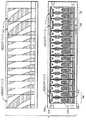
図1は、本発明の一実施形態例によるメタ・ディスク集合モデルを実施するシステム100を示す。本実施形態では、システム100は記憶制御装置102を含む。例えば、記憶制御装置102は、Engenio(商標)記憶制御装置である。この実施形態例では、記憶制御装置100は、Fibre Channel(FC)、インターネットSCSI(iSCSI)、又はシリアル取付SCSI(SAS)接続等を通じて、サーバ104と接続し通信するように構成される。Now, preferred embodiments of the present invention will be described in detail with reference to the accompanying drawings.
FIG. 1 illustrates a
この実施形態では、システム100は、更に、複数のディスク・ドライブ108を含むメタ・ディスク・ドライブ・グループ106も含む。この実施形態例では、メタ・ディスク・ドライブ・グループ106は、Fibre Channel(FC)又はシリアル取付SCSI(SAS)等を通じて記憶制御装置102と接続し通信するように構成されている。本実施形態では、メタ・ディスク・ドライブ・グループ106の複数のディスク・ドライブ108は、1つのドライブとして記憶制御装置102と通信するように構成されている。例えば、メタ・ディスク・ドライブ・グループ106は複数のディスク・ドライブ108を含むが、記憶制御装置102は複数のディスク・ドライブを1つのデバイス(例えば、1つのメタ・ディスク・スピンドル)であるかのように解釈する。つまり、1つのデバイス・アドレスをメタ・ディスク・ドライブ・グループ106に割り当てることができ、これによってシステム100に対してI/Oスループット向上、及び記憶密度の増大を促進する。実施形態例では、I/Oトラフィックは、記憶制御装置102のバック・エンド・チャネルを通じて、メタ・ディスク・ドライブ・グループの1つのデバイス・アドレスに送出する。 In this embodiment, the
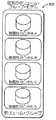
図2に示すように、一例の実施形態では、メタ・ディスク・ドライブ・グループの複数のディスク・ドライブ108に含まれる各ディスク・ドライブは、ドライブ抜出メカニズム(drive pull mechanism)204を有するドライブ・キャリア・アセンブリ202を含む。この実施形態では、各ドライブ抜出メカニズム204は、ドライブ・キャリア・アセンブリ202をドライブ・エンクロージャ208の中に固着するための抜き取り錠206を含み、この抜き取り錠は、ドライブ・キャリア・アセンブリ及びディスク・ドライブのドライブ・エンクロージャからの抜き取りを可能にするように、解除可能となっている。付加的な実施形態では、各ドライブ抜出メカニズム204は、ドライブ・キャリア・アセンブリ202及びディスク・ドライブのドライブ・エンクロージャからの抜き取りを容易にする抜き取りレバー210も含む。一例の実施形態では、メタ・ディスク・ドライブ・グループ106のディスク・ドライブ108のドライブ抜出メカニズム204の各々は、例えば、ユーザがメタ・ディスク・ドライブ・グループ106のディスク・キャリア・アセンブリ202及びディスク・ドライブ108をドライブ・エンクロージャから抜き取っている、即ち、取り外している間、メタ・ディスク・ドライブ・グループ106の残りのドライブ・キャリア・アセンブリ及びディスク・ドライブ108の各々も抜き取られるように、連動し同期が取られている。図2に示すように、多数のメタ・ディスク・ドライブ・グループ106を1つのドライブ・エンクロージャ208によって囲うことができる。 As shown in FIG. 2, in one example embodiment, each disk drive included in the plurality of
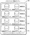
別の実施形態では、ディスク・ドライブ108を所望の容量となるように集合させて、適宜数のディスク・ドライブを有するメタ・ディスク・ドライブ・グループ106を形成することもできる。図5Bに示すように、別の実施形態では、多数のメタ・ディスク・ドライブ・グループ106をシステム100に含ませることができ、従来技術のボリューム・グループ502(図5A参照)に対して、容量増大及びI/O性能帯域幅拡大を促進するボリューム・グループ500を設けることもできる。 In another embodiment, the
図3に示すように、別の実施形態では、メタ・ディスク・ドライブ・グループ106の複数のドライブ108の各々は、ドライブ・インターフェース・コネクタ302を含む。更に、メタ・ディスク・ドライブ・グループ106の複数のディスク・ドライブ108は各々、ディスク・ドライブのドライブ・インターフェース・コネクタ302を通じて、メタ・ディスク・ドライブ・グループの複数のディスク・ドライブの各々を通信可能な状態に接続するために、ジャンパ304(例えば、介入ジャンパ(interposer jumper)のような、起動時介入電子回路(on-interposer electronics)も含む。一例の実施形態では、各ジャンパ304は、メタディスク・ドライブ・グループ106の複数のディスク・ドライブ108の集合を、記憶制御装置102に示すように構成されている。例えば、集合(aggregation)は、記憶制御装置のブート・アップ中(例えば、電力投入時)、又は記憶制御装置によってデバイス発見が行われるときに、記憶制御装置に示すことができる。 As shown in FIG. 3, in another embodiment, each of the plurality of
図4は、本発明の一実施形態による、記憶制御装置用メタ・ディスク集合モデルを実装する方法を示すフロー・チャートである。該方法400は、サーバと通信可能に構成されている記憶制御装置を提供するステップ(402)を含む。更に、方法400は、メタ・ディスク・ドライブ・グループを提供するステップ(404)を含み、メタ・ディスク・ドライブ・グループは、複数のディスク・ドライブを含む。更に、方法400は、1つのデバイスとして記憶制御装置と通信可能となるように、メタ・ディスク・ドライブ・グループを構成するステップ(406)も含む。更に、方法400は、メタ・ディスク・ドライブ・グループの複数のディスク・ドライブの各ディスク・ドライブに、ドライブ・キャリア・アセンブリを設置するステップ(408)を含み、各ドライブ・キャリア・アセンブリはドライブ抜出メカニズムを有し、各ドライブ抜出メカニズムは、メタ・ディスク・ドライブ・グループの残りのドライブ抜出メカニズムと同期が取られている。更に、方法400は、メタ・ディスク・ドライブ・グループのドライブ抜出メカニズムの各々を、連動ドライブ抜出メカニズムとして構成するステップ(410)を含む。更に、方法400は、メタ・ディスク・ドライブ・グループのドライブ抜出メカニズムの各々に、抜き取り錠及び抜き取りレバーの少なくとも1つを設置するステップ(412)を含む。更に、方法400は、メタ・ディスク・ドライブ・グループの複数のディスク・ドライブの各々に、ドライブ・インターフェース・コネクタ及びジャンパを設置するステップ(414)を含む。更に、方法400は、メタ・ディスク・ドライブ・グループの通信結合を可能にし、更にメタ・ディスク・ドライブ・グループのディスク・ドライブが1つのデバイスとして記憶制御装置と通信できるようにするために、ディスク・ドライブのジャンパを通じてディスク・ドライブのドライブ・インターフェース・コネクタの各々を橋絡する(bridging)ステップ(416)も含む。 FIG. 4 is a flow chart illustrating a method of implementing a storage controller meta-disk aggregate model according to one embodiment of the invention. The
尚、コンピュータ技術の当業者には明白であろうが、以上説明した本発明による実施形態は、本明細書の教示にしたがって汎用ディジタル・コンピュータをプログラムし、これを用いて実現することができるという利便性がある。本開示の教示に基づいて、習熟したプログラマであればしかるべきソフトウェア・コーディングを容易に提供することができる。これも、ソフトウェア技術の当業者には明白であろう。 As will be apparent to those skilled in the computer arts, the embodiments of the present invention described above can be implemented using and programming a general purpose digital computer in accordance with the teachings herein. There is convenience. Based on the teachings of the present disclosure, a skilled programmer can readily provide appropriate software coding. This will also be apparent to those skilled in the software art.
尚、本発明は、ソフトウェア・パッケージの形態でも実現することができるという利便性があることは、理解されるであろう。このようなソフトウェア・パッケージは、開示した本発明の機能やプロセスを実行するようにコンピュータをプログラムする際に用いられるコンピュータ・コードを格納した、コンピュータ読み取り可能記憶媒体を用いるコンピュータ・プラグラム製品とすることができる。コンピュータ読み取り可能記憶媒体は、あらゆる種類の従来からのフロッピ・ディスク、光ディスク、CD−ROM、磁気ディスク、ハード・ディスク・ドライブ、光磁気ディスク、ROM、RAM、EPROM、EEPROM、磁気又は光カード、あるいは電子命令を格納するのに適するのであれば他の任意の記憶媒体を含むことができるが、これらに限定されるのではない。 It will be appreciated that the present invention has the convenience that it can also be implemented in the form of a software package. Such a software package is a computer program product using a computer readable storage medium that stores computer code used to program a computer to perform the disclosed functions and processes of the present invention. Can do. Computer readable storage media can be any kind of conventional floppy disk, optical disk, CD-ROM, magnetic disk, hard disk drive, magneto-optical disk, ROM, RAM, EPROM, EEPROM, magnetic or optical card, or Any other storage medium may be included as long as it is suitable for storing electronic instructions, but is not limited thereto.
尚、以上に開示した方法におけるステップの具体的な順序又はステップの階層は、代表的な手法の例であることは言うまでもない。設計の優先度に基づいて、前述の方法における具体的な順序又はステップの階層を並び換えることができ、それでもなお本発明の範囲に該当することは言うまでもない。添付する方法の請求項は、種々のステップの要素を見本の順序で呈示するのであり、呈示する具体的な順序又は階層に限定することを意味するのではない。 Needless to say, the specific order of steps or the hierarchy of steps in the method disclosed above is an example of a typical technique. Of course, the specific order or step hierarchy in the above-described method can be rearranged based on design priority and still fall within the scope of the present invention. The accompanying method claims present elements of the various steps in a sample order, and are not meant to be limited to the specific order or hierarchy presented.
本発明及びそれに伴う利点の多くは、以上の説明によって理解されると確信する。また、本発明の範囲及び主旨から逸脱せずに、又はその重要な利点の全てを犠牲にすることなく、その構成要素の形態、構造、及び配置には種々の変更が可能であることは明白であることも確信する。これまでにこの中で記載した形態は、その説明のための一実施形態に過ぎず、本発明はこのような変更を包含し含むことを意図している。 It is believed that many of the invention and the attendant advantages will be understood from the foregoing description. Also, it will be apparent that various changes may be made in the form, structure and arrangement of the components without departing from the scope and spirit of the invention or without sacrificing all of its important advantages. I am sure that. The form so far described herein is merely one illustrative embodiment, and the present invention is intended to encompass and include such modifications.
Claims (13)
Translated fromJapaneseサーバと通信可能に接続されている記憶制御装置と、
それぞれが複数のディスク・ドライブを含み、かつ前記記憶制御装置と通信可能に接続されている複数のメタ・ディスク・ドライブ・グループからなる1つのメタ・ディスク・ボリューム・グループであって、前記メタ・ディスク・ドライブ・グループ各々に1つのデバイス・アドレスが割り当てられており、前記複数のディスク・ドライブの各々が、ドライブ・インターフェース・コネクタを介して前記ディスク・ドライブの各々と通信可能に接続するためのイネーブル/ディスエーブル・ジャンパを備えている、前記複数のメタ・ディスク・ドライブ・グループからなるメタ・ディスク・ボリューム・グループと
を備えており、
前記メタ・ディスク・ドライブ・グループの各々の複数のディスク・ドライブの各ドライブ・インターフェース・コネクタは、前記複数のディスク・ドライブの残りのドライブ・インターフェース・コネクタの各々と通信可能に接続されており、これによって前記メタディスク・ドライブ・グループ各々の前記複数のディスク・ドライブが1つのデバイスとして前記記憶制御装置と通信することを可能にし、
前記メタ・ディスク・ドライブ・グループ各々の複数のディスク・ドライブの各々は、ドライブ抜出メカニズムを有するドライブ・キャリア・アセンブリを含み、各ドライブ抜出メカニズムは、単一のドライブ・エンクロージャからのディスク・ドライブ及びドライブ・キャリア・アセンブリの抜き出しを可能にするように構成されており、前記メタ・ディスク・ドライブ・グループの内の特定のメタ・ディスク・ドライブ・グループの各ドライブ抜出メカニズムは、前記特定のメタ・ディスク・ドライブ・グループの残りのドライブ抜出メカニズムと同期が取られて、前記単一のドライブ・エンクロージャからの前記特定のメタ・ディスク・ドライブ・グループのディスク・ドライブ及びドライブ・キャリア・アセンブリの全てを一度で同時一括に抜き出すことができるように構成されており、
前記単一のドライブ・エンクロージャは、前記メタ・ディスク・ボリューム・グループの前記メタ・ディスク・ドライブ・グループの全てを囲っており、
前記メタ・ディスク・ボリューム・グループの前記メタ・ディスク・ドライブ・グループ各々の単一デバイス・アドレスに対して、前記記憶制御装置のバック・エンド・チャネルを介して入力/出力トラフィックが向けられ、
前記メタ・ディスク・ボリューム・グループは、前記メタ・ディスク・ボリューム・グループに含まれる前記メタ・ディスク・ドライブ・グループの数と同一の個々のディスク・ドライブを有するボリューム・グループの入出力帯域及び記憶密度と対比して、より大きな入出力帯域及び記憶密度を有している
ことを特徴とするシステム。A system,
A storage control device communicably connected to the server;
One meta disk volume group comprising a plurality of meta disk drive groups each including a plurality of disk drives and communicatively connected to the storage controller, wherein the meta disk One device address is assigned to each disk drive group, and each of the plurality of disk drives is communicatively connected to each of the disk drives via a drive interface connector. A meta disk volume group comprising the plurality of meta disk drive groups with an enable / disable jumper;
Each drive interface connector of each of the plurality of disk drives in the meta disk drive group is communicatively connected to each of the remaining drive interface connectors of the plurality of disk drives; This allows the plurality of disk drives in each of the metadisk drive groups to communicate with the storage controller as a single device,
Each of the plurality of disk drives in each of the meta disk drive groups includes a drive carrier assembly having a drive extraction mechanism, each drive extraction mechanism including a disk drive from a single drive enclosure. The drive and drive carrier assembly is configured to be removable, and each drive extraction mechanism of a specific meta disk drive group within the meta disk drive group is The disk drive and drive carrier of the particular meta disk drive group from the single drive enclosure are synchronized with the remaining drive extraction mechanism of the meta disk drive group of Same assembly all at once Is configured so that it can be withdrawn in bulk,
The single drive enclosure surrounds all of the meta disk drive groups of the meta disk volume group;
Input / output traffic is directed through a back end channel of the storage controller to a single device address of each of the meta disk drive groups of the meta disk volume group;
The meta disk volume group includes the input / output bandwidth and storage of a volume group having the same number of individual disk drives as the number of the meta disk drive groups included in the meta disk volume group. A system characterized by having a larger input / output bandwidth and storage density compared to density.
サーバと通信可能に構成された記憶制御装置を提供するステップと、
メタ・ディスク・ボリューム・グループの複数のメタ・ディスク・ドライブ・グループを提供するステップであって、前記メタ・ディスク・ドライブ・グループの各々が複数のディスク・ドライブを含み、
前記メタ・ディスク・ドライブ・グループの各々に単一のデバイス・アドレスを割り当てるステップと、
前記メタ・ディスク・ドライブ・グループの各々が前記記憶制御装置と通信可能となるように設定するステップであって、前記複数のディスク・ドライブの各々が、ドライブ・インターフェース・コネクタを介してこれらディスク・ドライブのそれぞれと相互に通信可能とするためのジャンパを備えている、ステップと、
前記ディスク・ドライブ・インターフェース・コネクタの各々を、前記複数のディスク・ドライブの残りのドライブ・インターフェース・コネクタと相互に通信可能に接続するステップと、
前記メタ・ディスク・ドライブ・グループの各々の前記複数のディスク・ドライブのそれぞれを、単一のデバイスとして前記記憶制御装置と通信可能にするステップと、
前記メタ・ディスク・ドライブ・グループの前記ディスク・ドライブの各々に、ドライブ・キャリア・アセンブリを設置するステップであって、各ドライブ・キャリア・アセンブリはドライブ抜出メカニズムを有し、各ドライブ抜出メカニズムは、単一のドライブ・エンクロージャからのディスク・ドライブ及びドライブ・キャリア・アセンブリの抜き出しを可能にするように構成されており、特定のメタ・ディスク・ドライブ・グループの各ドライブ抜出メカニズムは、前記特定のメタ・ディスク・ドライブ・グループの残りのドライブ抜出メカニズムと同期を取られて、前記単一のドライブ・エンクロージャから前記特定のメタ・ディスク・ドライブ・グループのディスク・ドライブ及びドライブ・キャリア・アセンブリの全てを同時一括で抜き出すことができるよう構成されている、ステップと、
前記メタ・ディスク・ドライブ・グループのドライブ抜出メカニズムの各々を、連動ドライブ抜出メカニズムとして構成するステップと
を含む、メタ・ディスク・ドライブ・グループを提供するステップと、
前記メタ・ディスク・ボリューム・グループの前記メタ・ディスク・ドライブ・グループの全てを囲む前記単一のドライブ・エンクロージャを提供するステップと
を備え、
前記メタ・ディスク・ボリューム・グループの前記メタ・ディスク・ドライブ・グループの各々の前記単一デバイス・アドレスに対して、前記記憶制御装置のバック・エンド・チャネルを介して入力/出力トラフィックが向けられ、
前記メタ・ディスク・ボリューム・グループは、前記メタ・ディスク・ボリューム・グループに含まれる前記メタ・ディスク・ドライブ・グループの数と同一の個々のディスク・ドライブを有するボリューム・グループの入出力帯域及び記憶密度と対比して、より大きな入出力帯域及び記憶密度を有している
ことを特徴とする方法。A method,
Providing a storage controller configured to communicate with a server;
Providing a plurality of meta disk drive groups for a meta disk volume group, each of the meta disk drive groups including a plurality of disk drives;
Assigning a single device address to each of said meta disk drive groups;
Setting each of the meta disk drive groups to be communicable with the storage controller, wherein each of the plurality of disk drives is connected to the disk drive via a drive interface connector. A step with jumpers to allow each of the drives to communicate with each other;
Communicatively connecting each of the disk drive interface connectors with the remaining drive interface connectors of the plurality of disk drives;
Enabling each of the plurality of disk drives in each of the meta disk drive groups to communicate with the storage controller as a single device;
Installing a drive carrier assembly in each of the disk drives of the meta disk drive group, each drive carrier assembly having a drive extraction mechanism, each drive extraction mechanism Are configured to allow extraction of disk drives and drive carrier assemblies from a single drive enclosure, and each drive extraction mechanism for a particular meta disk drive group includes: Synchronized with the remaining drive extraction mechanism of a particular meta disk drive group, the disk drives and drive carrier drives of the particular meta disk drive group from the single drive enclosure One assembly at a time It is extracted by being configured to allow the steps,
Providing a meta disk drive group comprising: configuring each of the drive extraction mechanisms of the meta disk drive group as an interlocked drive extraction mechanism;
Providing the single drive enclosure enclosing all of the meta disk drive groups of the meta disk volume group;
Input / output traffic is directed through the back end channel of the storage controller to the single device address of each of the meta disk drive groups of the meta disk volume group. ,
The meta disk volume group includes the input / output bandwidth and storage of a volume group having the same number of individual disk drives as the number of the meta disk drive groups included in the meta disk volume group. A method characterized by having a larger input / output bandwidth and storage density compared to density.
前記メタ・ディスク・ドライブ・グループのドライブ抜出メカニズムの各々に、抜き取り錠及び抜き取りレバーの内少なくとも1つを設置するステップ
を備えていることを特徴とする方法。8. The method of claim 7, wherein providing the plurality of meta disk drive groups further comprises:
A method comprising the step of installing at least one of an extraction lock and an extraction lever in each of the drive extraction mechanisms of the meta disk drive group.
前記メタ・ディスク・ドライブ・グループのディスク・ドライブを通信接続可能にし、更に前記メタ・ディスク・ドライブ・グループのディスク・ドライブが1つのデバイスとして前記記憶制御装置と通信できるようにするために、前記ディスク・ドライブのジャンパを通じて前記ディスク・ドライブのドライブ・インターフェース・コネクタの各々を橋絡するステップ
を備えていることを特徴とする方法。8. The method of claim 7, further comprising the step of configuring the meta disk drive group to be communicable with the storage controller as a single device.
In order to enable communication connection of the disk drives of the meta disk drive group, and to enable the disk drives of the meta disk drive group to communicate with the storage controller as one device, A method comprising bridging each of the disk drive drive interface connectors through a disk drive jumper.
サーバと通信可能に構成されている記憶制御装置と、
それぞれが複数のディスク・ドライブを含む複数のメタ・ディスク・ドライブ・グループを含んだメタ・ディスク・ボリューム・グループであって、該メタ・ディスク・ドライブ・グループ各々は、単一のデバイス・アドレスが割り当てられており、かつ、前記記憶制御装置と通信可能に接続されており、複数のディスク・ドライブの各ディスク・ドライブは、ジャンパを備えて、これら複数のディスク・ドライブがドライブ・インターフェース接続部を介して相互に通信可能に構成されており、前記メタ・ディスク・ドライブ・グループ各々の前記複数のディスク・ドライブの前記ドライブ・インターフェース接続部は、前記複数のディスク・ドライブの残りのドライブ・インターフェース接続部のそれぞれと相互に通信可能であって、前記メタ・ディスク・ドライブ・グループ各々の前記複数のディスク・ドライブが1つのデバイスとして前記記憶制御装置と通信可能であり、かつ、前記メタディスク・ドライブ・グループ各々の前記複数のディスク・ドライブ各々は、ドライブ抜出メカニズムを含むドライブ・キャリア・アセンブリを有し、各ドライブ抜出メカニズムは、単一のドライブ・エンクロージャからのディスク・ドライブ及びドライブ・キャリア・アセンブリを除去可能に構成されており、前記メタ・ディスク・ドライブ・グループの特定のメタ・ディスク・ドライブ・グループの各ドライブ抜出メカニズムは、前記特定のメタ・ディスク・ドライブ・グループの残りのドライブ抜出メカニズムと連動し、かつ同期を取られており、これによって前記単一のドライブ・エンクロージャから各ディスク・ドライブ及びドライブ・キャリア・アセンブリの全てを同時一括で除去可能とし、前記メタ・ディスク・ドライブ・グループの各ドライブ抜出メカニズムは、抜き取り錠及び抜き取りレバーを含み、前記メタ・ディスク・ドライブ・グループは、前記記憶制御装置と通信可能に構成されている、メタ・ディスク・ドライブ・グループと
を備えており、
前記単一のドライブ・エンクロージャは、前記メタ・ディスク・ボリューム・グループの前記メタ・ディスク・ドライブ・グループの全てを囲っており、
前記メタ・ディスク・ボリューム・グループの前記メタ・ディスク・ドライブ・グループ各々の単一デバイス・アドレスに対して、前記記憶制御装置のバック・エンド・チャネルを介して入力/出力トラフィックが向けられ、
前記メタ・ディスク・ボリューム・グループは、前記メタ・ディスク・ボリューム・グループに含まれる前記メタ・ディスク・ドライブ・グループの数と同一の個々のディスク・ドライブを有するボリューム・グループの入出力帯域及び記憶密度と対比して、より大きな入出力帯域及び記憶密度を有している
ことを特徴とするシステム。A system,
A storage controller configured to communicate with the server;
A meta disk volume group including a plurality of meta disk drive groups each including a plurality of disk drives, each of the meta disk drive groups having a single device address Assigned to the storage controller, and each disk drive of the plurality of disk drives includes a jumper, and the plurality of disk drives have a drive interface connection. And the drive interface connections of the plurality of disk drives in each of the meta disk drive groups are connected to the remaining drive interfaces of the plurality of disk drives. Can communicate with each other, The plurality of disk drives in each of the meta disk drive groups can communicate with the storage controller as one device, and each of the plurality of disk drives in each of the meta disk drive groups includes: A drive carrier assembly including a drive extraction mechanism, each drive extraction mechanism configured to remove a disk drive and drive carrier assembly from a single drive enclosure; Each drive extraction mechanism of a specific meta disk drive group in a disk drive group is synchronized with and synchronized with the remaining drive extraction mechanisms of the specific meta disk drive group. And the single dry All of the disk drives and drive carrier assemblies can be removed simultaneously from the enclosure, and each drive extraction mechanism of the meta disk drive group includes an extraction lock and an extraction lever. The disk drive group includes a meta disk drive group configured to be able to communicate with the storage control device,
The single drive enclosure surrounds all of the meta disk drive groups of the meta disk volume group;
Input / output traffic is directed through a back end channel of the storage controller to a single device address of each of the meta disk drive groups of the meta disk volume group;
The meta disk volume group includes the input / output bandwidth and storage of a volume group having the same number of individual disk drives as the number of the meta disk drive groups included in the meta disk volume group. A system characterized by having a larger input / output bandwidth and storage density compared to density.
Applications Claiming Priority (2)
| Application Number | Priority Date | Filing Date | Title |
|---|---|---|---|
| US11/585,524 | 2006-10-24 | ||
| US11/585,524US8385061B2 (en) | 2006-10-24 | 2006-10-24 | System and method for implementing a meta-disk aggregation model for storage controllers |
Related Parent Applications (1)
| Application Number | Title | Priority Date | Filing Date |
|---|---|---|---|
| JP2009534580ADivisionJP2010507867A (en) | 2006-10-24 | 2007-09-28 | System and method for implementing a meta-disk aggregate model for a storage controller |
Publications (1)
| Publication Number | Publication Date |
|---|---|
| JP2013041606Atrue JP2013041606A (en) | 2013-02-28 |
Family
ID=39319417
Family Applications (2)
| Application Number | Title | Priority Date | Filing Date |
|---|---|---|---|
| JP2009534580APendingJP2010507867A (en) | 2006-10-24 | 2007-09-28 | System and method for implementing a meta-disk aggregate model for a storage controller |
| JP2012232276ACeasedJP2013041606A (en) | 2006-10-24 | 2012-10-19 | System and method for implementing meta-disk aggregation model for storage controllers |
Family Applications Before (1)
| Application Number | Title | Priority Date | Filing Date |
|---|---|---|---|
| JP2009534580APendingJP2010507867A (en) | 2006-10-24 | 2007-09-28 | System and method for implementing a meta-disk aggregate model for a storage controller |
Country Status (5)
| Country | Link |
|---|---|
| US (1) | US8385061B2 (en) |
| EP (1) | EP2087432A4 (en) |
| JP (2) | JP2010507867A (en) |
| CN (1) | CN101523363B (en) |
| WO (1) | WO2008051353A2 (en) |
Families Citing this family (2)
| Publication number | Priority date | Publication date | Assignee | Title |
|---|---|---|---|---|
| CN101778138A (en)* | 2010-02-01 | 2010-07-14 | 成都市华为赛门铁克科技有限公司 | Memory system and data transmission method |
| US8886910B2 (en) | 2011-09-12 | 2014-11-11 | Microsoft Corporation | Storage device drivers and cluster participation |
Citations (15)
| Publication number | Priority date | Publication date | Assignee | Title |
|---|---|---|---|---|
| JPH04153727A (en)* | 1990-10-18 | 1992-05-27 | Nec Field Service Ltd | Magnetic disk system |
| JPH076004A (en)* | 1993-04-22 | 1995-01-10 | Bull Sa | Physical structure of the mass storage subsystem |
| JPH07105633A (en)* | 1990-07-09 | 1995-04-21 | Seagate Technol Internatl | Disk drive array data recovery channel |
| JPH096547A (en)* | 1995-06-16 | 1997-01-10 | Hitachi Ltd | Information processing apparatus and method of driving external storage device |
| JPH0950353A (en)* | 1995-08-04 | 1997-02-18 | Matsushita Electric Ind Co Ltd | Library type storage device |
| JPH09305323A (en)* | 1996-05-14 | 1997-11-28 | Toshiba Corp | Disk storage system |
| JP2000508458A (en)* | 1996-11-14 | 2000-07-04 | データー・ゼネラル・コーポレーション | Dynamic updatable disk array system and method |
| JP2002042446A (en)* | 2000-07-26 | 2002-02-08 | Hirota Seisakusho:Kk | Inspection apparatus for hard disks |
| JP2002318667A (en)* | 2001-01-31 | 2002-10-31 | Hewlett Packard Co <Hp> | Integrated storage system |
| JP2004086251A (en)* | 2002-08-22 | 2004-03-18 | Nec Corp | Duplex controller for information record reproduction device, method and duplex control program |
| JP2005267239A (en)* | 2004-03-18 | 2005-09-29 | Hitachi Global Storage Technologies Netherlands Bv | Storage device and method for transferring files between storage devices |
| JP2005293547A (en)* | 2004-03-11 | 2005-10-20 | Hitachi Ltd | Storage device |
| JP2005322385A (en)* | 2004-04-02 | 2005-11-17 | Seagate Technology Llc | Carrier device and method for multiple disc array |
| JP2006235696A (en)* | 2005-02-22 | 2006-09-07 | Hitachi Ltd | Disk unit |
| JP2008537805A (en)* | 2004-12-13 | 2008-09-25 | シエラ・ロジック、インコーポレイテッド | Integrated circuit implementation of a storage shelf router and path control card for use in combination in a high availability mass storage shelf that can be incorporated into a disk array |
Family Cites Families (8)
| Publication number | Priority date | Publication date | Assignee | Title |
|---|---|---|---|---|
| US6438661B1 (en) | 1999-03-03 | 2002-08-20 | International Business Machines Corporation | Method, system, and program for managing meta data in a storage system and rebuilding lost meta data in cache |
| US6795895B2 (en) | 2001-03-07 | 2004-09-21 | Canopy Group | Dual axis RAID systems for enhanced bandwidth and reliability |
| US6724635B2 (en)* | 2001-08-07 | 2004-04-20 | Hewlett-Packard Development Company, L.P. | LCD panel for a server system |
| WO2003014892A2 (en)* | 2001-08-10 | 2003-02-20 | Sun Microsystems, Inc | Server blade |
| US20030033463A1 (en)* | 2001-08-10 | 2003-02-13 | Garnett Paul J. | Computer system storage |
| US7000037B2 (en) | 2002-10-24 | 2006-02-14 | Josef Rabinovitz | Large array of mass data storage devices connected to a computer by a serial link |
| US7167929B2 (en) | 2003-01-13 | 2007-01-23 | Sierra Logic | Integrated-circuit implementation of a storage-shelf router and a path controller card for combined use in high-availability mass-storage-device shelves that may be incorporated within disk arrays, and a storage-shelf-interface tunneling method and system |
| US7415543B2 (en)* | 2003-11-12 | 2008-08-19 | Lsi Corporation | Serial port initialization in storage system controllers |
- 2006
- 2006-10-24USUS11/585,524patent/US8385061B2/ennot_activeExpired - Fee Related
- 2007
- 2007-09-28WOPCT/US2007/021085patent/WO2008051353A2/enactiveApplication Filing
- 2007-09-28CNCN2007800378954Apatent/CN101523363B/ennot_activeExpired - Fee Related
- 2007-09-28EPEP07839105Apatent/EP2087432A4/ennot_activeWithdrawn
- 2007-09-28JPJP2009534580Apatent/JP2010507867A/enactivePending
- 2012
- 2012-10-19JPJP2012232276Apatent/JP2013041606A/ennot_activeCeased
Patent Citations (15)
| Publication number | Priority date | Publication date | Assignee | Title |
|---|---|---|---|---|
| JPH07105633A (en)* | 1990-07-09 | 1995-04-21 | Seagate Technol Internatl | Disk drive array data recovery channel |
| JPH04153727A (en)* | 1990-10-18 | 1992-05-27 | Nec Field Service Ltd | Magnetic disk system |
| JPH076004A (en)* | 1993-04-22 | 1995-01-10 | Bull Sa | Physical structure of the mass storage subsystem |
| JPH096547A (en)* | 1995-06-16 | 1997-01-10 | Hitachi Ltd | Information processing apparatus and method of driving external storage device |
| JPH0950353A (en)* | 1995-08-04 | 1997-02-18 | Matsushita Electric Ind Co Ltd | Library type storage device |
| JPH09305323A (en)* | 1996-05-14 | 1997-11-28 | Toshiba Corp | Disk storage system |
| JP2000508458A (en)* | 1996-11-14 | 2000-07-04 | データー・ゼネラル・コーポレーション | Dynamic updatable disk array system and method |
| JP2002042446A (en)* | 2000-07-26 | 2002-02-08 | Hirota Seisakusho:Kk | Inspection apparatus for hard disks |
| JP2002318667A (en)* | 2001-01-31 | 2002-10-31 | Hewlett Packard Co <Hp> | Integrated storage system |
| JP2004086251A (en)* | 2002-08-22 | 2004-03-18 | Nec Corp | Duplex controller for information record reproduction device, method and duplex control program |
| JP2005293547A (en)* | 2004-03-11 | 2005-10-20 | Hitachi Ltd | Storage device |
| JP2005267239A (en)* | 2004-03-18 | 2005-09-29 | Hitachi Global Storage Technologies Netherlands Bv | Storage device and method for transferring files between storage devices |
| JP2005322385A (en)* | 2004-04-02 | 2005-11-17 | Seagate Technology Llc | Carrier device and method for multiple disc array |
| JP2008537805A (en)* | 2004-12-13 | 2008-09-25 | シエラ・ロジック、インコーポレイテッド | Integrated circuit implementation of a storage shelf router and path control card for use in combination in a high availability mass storage shelf that can be incorporated into a disk array |
| JP2006235696A (en)* | 2005-02-22 | 2006-09-07 | Hitachi Ltd | Disk unit |
Also Published As
| Publication number | Publication date |
|---|---|
| US8385061B2 (en) | 2013-02-26 |
| CN101523363B (en) | 2013-09-25 |
| CN101523363A (en) | 2009-09-02 |
| WO2008051353A3 (en) | 2008-07-10 |
| WO2008051353A2 (en) | 2008-05-02 |
| EP2087432A4 (en) | 2010-06-02 |
| US20080098171A1 (en) | 2008-04-24 |
| EP2087432A2 (en) | 2009-08-12 |
| JP2010507867A (en) | 2010-03-11 |
Similar Documents
| Publication | Publication Date | Title |
|---|---|---|
| US8904158B2 (en) | Storage system with boot appliance for improving reliability/availability/serviceability in high density server environments | |
| KR102355974B1 (en) | Solid state drive multi-card adapter with integrated processing | |
| US10466923B2 (en) | Modular non-volatile flash memory blade | |
| CN1257447C (en) | Adapters, Transition Data Storage Devices, and Operations for Converting Data Storage Devices | |
| JP2019153300A (en) | SYSTEM AND METHOD FOR SUPPORTING MULTI-MODE AND/OR MULTI-SPEED NVMe-oF DEVICES | |
| US10162786B2 (en) | Storage node based on PCI express interface | |
| US9734106B2 (en) | Systems and methods for providing connections to an information handling system | |
| JP4688514B2 (en) | Storage controller | |
| US20110113159A1 (en) | Communication with input/output system devices | |
| US8495290B2 (en) | Methods for implementation of an array of removable disk drives | |
| US20170220506A1 (en) | Modular Software Defined Storage Technology | |
| US20110271065A1 (en) | Storage system front end with protocol translation | |
| EP1597661A2 (en) | Serial advanced technology attachment interface | |
| US7610418B2 (en) | Maximizing blade slot utilization in a storage blade enclosure | |
| EP2837149B1 (en) | Methods and systems for virtualization of storage services in an integrated chassis | |
| JP2013041606A (en) | System and method for implementing meta-disk aggregation model for storage controllers | |
| CN106502657A (en) | A kind of method for realizing that based on linux automatizatioies HBA cards hard disk configures RAID | |
| CN118885222A (en) | Multimedia card mounting method, device, storage medium, and electronic device | |
| US20140075065A1 (en) | Multi-Use Adapters, Solid State Storage Modules and High Capacity Storage Systems | |
| CN101320313A (en) | storage device | |
| WO2015077861A1 (en) | Camera supporting removable storage divided into multiple partitions | |
| US7506127B2 (en) | Reconfiguration of storage system including multiple mass storage devices | |
| US7934026B2 (en) | Apparatus and method to preserve one or more logical communication paths in a data processing system | |
| CN108027795A (en) | Modular backplane | |
| CN110941392A (en) | Method and apparatus for emulating a remote storage device as a local storage device |
Legal Events
| Date | Code | Title | Description |
|---|---|---|---|
| A977 | Report on retrieval | Free format text:JAPANESE INTERMEDIATE CODE: A971007 Effective date:20131129 | |
| A131 | Notification of reasons for refusal | Free format text:JAPANESE INTERMEDIATE CODE: A131 Effective date:20131205 | |
| A521 | Written amendment | Free format text:JAPANESE INTERMEDIATE CODE: A523 Effective date:20140305 | |
| RD03 | Notification of appointment of power of attorney | Free format text:JAPANESE INTERMEDIATE CODE: A7423 Effective date:20140801 | |
| RD04 | Notification of resignation of power of attorney | Free format text:JAPANESE INTERMEDIATE CODE: A7424 Effective date:20140804 | |
| A02 | Decision of refusal | Free format text:JAPANESE INTERMEDIATE CODE: A02 Effective date:20140930 | |
| A521 | Written amendment | Free format text:JAPANESE INTERMEDIATE CODE: A523 Effective date:20150108 | |
| A911 | Transfer to examiner for re-examination before appeal (zenchi) | Free format text:JAPANESE INTERMEDIATE CODE: A911 Effective date:20150116 | |
| A912 | Re-examination (zenchi) completed and case transferred to appeal board | Free format text:JAPANESE INTERMEDIATE CODE: A912 Effective date:20150206 | |
| A045 | Written measure of dismissal of application [lapsed due to lack of payment] | Free format text:JAPANESE INTERMEDIATE CODE: A045 Effective date:20160322 |