JP2013041596A - Integration of process modules and expert systems in process plants - Google Patents
Integration of process modules and expert systems in process plantsDownload PDFInfo
- Publication number
- JP2013041596A JP2013041596AJP2012221298AJP2012221298AJP2013041596AJP 2013041596 AJP2013041596 AJP 2013041596AJP 2012221298 AJP2012221298 AJP 2012221298AJP 2012221298 AJP2012221298 AJP 2012221298AJP 2013041596 AJP2013041596 AJP 2013041596A
- Authority
- JP
- Japan
- Prior art keywords
- module
- expert
- plant
- graphic
- simulation
- Prior art date
- Legal status (The legal status is an assumption and is not a legal conclusion. Google has not performed a legal analysis and makes no representation as to the accuracy of the status listed.)
- Pending
Links
Images


Classifications
- G—PHYSICS
- G05—CONTROLLING; REGULATING
- G05B—CONTROL OR REGULATING SYSTEMS IN GENERAL; FUNCTIONAL ELEMENTS OF SUCH SYSTEMS; MONITORING OR TESTING ARRANGEMENTS FOR SUCH SYSTEMS OR ELEMENTS
- G05B19/00—Programme-control systems
- G05B19/02—Programme-control systems electric
- G05B19/04—Programme control other than numerical control, i.e. in sequence controllers or logic controllers
- G05B19/042—Programme control other than numerical control, i.e. in sequence controllers or logic controllers using digital processors
- G05B19/0426—Programming the control sequence
- G—PHYSICS
- G05—CONTROLLING; REGULATING
- G05B—CONTROL OR REGULATING SYSTEMS IN GENERAL; FUNCTIONAL ELEMENTS OF SUCH SYSTEMS; MONITORING OR TESTING ARRANGEMENTS FOR SUCH SYSTEMS OR ELEMENTS
- G05B19/00—Programme-control systems
- G05B19/02—Programme-control systems electric
- G—PHYSICS
- G05—CONTROLLING; REGULATING
- G05B—CONTROL OR REGULATING SYSTEMS IN GENERAL; FUNCTIONAL ELEMENTS OF SUCH SYSTEMS; MONITORING OR TESTING ARRANGEMENTS FOR SUCH SYSTEMS OR ELEMENTS
- G05B19/00—Programme-control systems
- G05B19/02—Programme-control systems electric
- G05B19/04—Programme control other than numerical control, i.e. in sequence controllers or logic controllers
- G05B19/042—Programme control other than numerical control, i.e. in sequence controllers or logic controllers using digital processors
- G05B19/0423—Input/output
- G05B19/0425—Safety, monitoring
- G—PHYSICS
- G05—CONTROLLING; REGULATING
- G05B—CONTROL OR REGULATING SYSTEMS IN GENERAL; FUNCTIONAL ELEMENTS OF SUCH SYSTEMS; MONITORING OR TESTING ARRANGEMENTS FOR SUCH SYSTEMS OR ELEMENTS
- G05B19/00—Programme-control systems
- G05B19/02—Programme-control systems electric
- G05B19/04—Programme control other than numerical control, i.e. in sequence controllers or logic controllers
- G05B19/042—Programme control other than numerical control, i.e. in sequence controllers or logic controllers using digital processors
- G05B19/0428—Safety, monitoring
- G—PHYSICS
- G05—CONTROLLING; REGULATING
- G05B—CONTROL OR REGULATING SYSTEMS IN GENERAL; FUNCTIONAL ELEMENTS OF SUCH SYSTEMS; MONITORING OR TESTING ARRANGEMENTS FOR SUCH SYSTEMS OR ELEMENTS
- G05B19/00—Programme-control systems
- G05B19/02—Programme-control systems electric
- G05B19/418—Total factory control, i.e. centrally controlling a plurality of machines, e.g. direct or distributed numerical control [DNC], flexible manufacturing systems [FMS], integrated manufacturing systems [IMS] or computer integrated manufacturing [CIM]
- G05B19/4185—Total factory control, i.e. centrally controlling a plurality of machines, e.g. direct or distributed numerical control [DNC], flexible manufacturing systems [FMS], integrated manufacturing systems [IMS] or computer integrated manufacturing [CIM] characterised by the network communication
- G—PHYSICS
- G05—CONTROLLING; REGULATING
- G05B—CONTROL OR REGULATING SYSTEMS IN GENERAL; FUNCTIONAL ELEMENTS OF SUCH SYSTEMS; MONITORING OR TESTING ARRANGEMENTS FOR SUCH SYSTEMS OR ELEMENTS
- G05B19/00—Programme-control systems
- G05B19/02—Programme-control systems electric
- G05B19/418—Total factory control, i.e. centrally controlling a plurality of machines, e.g. direct or distributed numerical control [DNC], flexible manufacturing systems [FMS], integrated manufacturing systems [IMS] or computer integrated manufacturing [CIM]
- G05B19/41885—Total factory control, i.e. centrally controlling a plurality of machines, e.g. direct or distributed numerical control [DNC], flexible manufacturing systems [FMS], integrated manufacturing systems [IMS] or computer integrated manufacturing [CIM] characterised by modeling, simulation of the manufacturing system
- G—PHYSICS
- G05—CONTROLLING; REGULATING
- G05B—CONTROL OR REGULATING SYSTEMS IN GENERAL; FUNCTIONAL ELEMENTS OF SUCH SYSTEMS; MONITORING OR TESTING ARRANGEMENTS FOR SUCH SYSTEMS OR ELEMENTS
- G05B23/00—Testing or monitoring of control systems or parts thereof
- G05B23/02—Electric testing or monitoring
- G05B23/0205—Electric testing or monitoring by means of a monitoring system capable of detecting and responding to faults
- G05B23/0259—Electric testing or monitoring by means of a monitoring system capable of detecting and responding to faults characterized by the response to fault detection
- G05B23/0267—Fault communication, e.g. human machine interface [HMI]
- G—PHYSICS
- G06—COMPUTING OR CALCULATING; COUNTING
- G06F—ELECTRIC DIGITAL DATA PROCESSING
- G06F11/00—Error detection; Error correction; Monitoring
- G06F11/30—Monitoring
- G06F11/32—Monitoring with visual or acoustical indication of the functioning of the machine
- G—PHYSICS
- G06—COMPUTING OR CALCULATING; COUNTING
- G06F—ELECTRIC DIGITAL DATA PROCESSING
- G06F13/00—Interconnection of, or transfer of information or other signals between, memories, input/output devices or central processing units
- G—PHYSICS
- G06—COMPUTING OR CALCULATING; COUNTING
- G06F—ELECTRIC DIGITAL DATA PROCESSING
- G06F13/00—Interconnection of, or transfer of information or other signals between, memories, input/output devices or central processing units
- G06F13/38—Information transfer, e.g. on bus
- G06F13/382—Information transfer, e.g. on bus using universal interface adapter
- G06F13/387—Information transfer, e.g. on bus using universal interface adapter for adaptation of different data processing systems to different peripheral devices, e.g. protocol converters for incompatible systems, open system
- G—PHYSICS
- G06—COMPUTING OR CALCULATING; COUNTING
- G06F—ELECTRIC DIGITAL DATA PROCESSING
- G06F16/00—Information retrieval; Database structures therefor; File system structures therefor
- G—PHYSICS
- G06—COMPUTING OR CALCULATING; COUNTING
- G06F—ELECTRIC DIGITAL DATA PROCESSING
- G06F8/00—Arrangements for software engineering
- G06F8/20—Software design
- G—PHYSICS
- G06—COMPUTING OR CALCULATING; COUNTING
- G06F—ELECTRIC DIGITAL DATA PROCESSING
- G06F8/00—Arrangements for software engineering
- G06F8/30—Creation or generation of source code
- G06F8/38—Creation or generation of source code for implementing user interfaces
- G—PHYSICS
- G06—COMPUTING OR CALCULATING; COUNTING
- G06F—ELECTRIC DIGITAL DATA PROCESSING
- G06F9/00—Arrangements for program control, e.g. control units
- G—PHYSICS
- G06—COMPUTING OR CALCULATING; COUNTING
- G06F—ELECTRIC DIGITAL DATA PROCESSING
- G06F9/00—Arrangements for program control, e.g. control units
- G06F9/06—Arrangements for program control, e.g. control units using stored programs, i.e. using an internal store of processing equipment to receive or retain programs
- G06F9/44—Arrangements for executing specific programs
- G06F9/448—Execution paradigms, e.g. implementations of programming paradigms
- G06F9/4488—Object-oriented
- G—PHYSICS
- G06—COMPUTING OR CALCULATING; COUNTING
- G06F—ELECTRIC DIGITAL DATA PROCESSING
- G06F9/00—Arrangements for program control, e.g. control units
- G06F9/06—Arrangements for program control, e.g. control units using stored programs, i.e. using an internal store of processing equipment to receive or retain programs
- G06F9/44—Arrangements for executing specific programs
- G06F9/451—Execution arrangements for user interfaces
- G—PHYSICS
- G06—COMPUTING OR CALCULATING; COUNTING
- G06N—COMPUTING ARRANGEMENTS BASED ON SPECIFIC COMPUTATIONAL MODELS
- G06N5/00—Computing arrangements using knowledge-based models
- G06N5/04—Inference or reasoning models
- G—PHYSICS
- G06—COMPUTING OR CALCULATING; COUNTING
- G06Q—INFORMATION AND COMMUNICATION TECHNOLOGY [ICT] SPECIALLY ADAPTED FOR ADMINISTRATIVE, COMMERCIAL, FINANCIAL, MANAGERIAL OR SUPERVISORY PURPOSES; SYSTEMS OR METHODS SPECIALLY ADAPTED FOR ADMINISTRATIVE, COMMERCIAL, FINANCIAL, MANAGERIAL OR SUPERVISORY PURPOSES, NOT OTHERWISE PROVIDED FOR
- G06Q10/00—Administration; Management
- G06Q10/06—Resources, workflows, human or project management; Enterprise or organisation planning; Enterprise or organisation modelling
- G—PHYSICS
- G06—COMPUTING OR CALCULATING; COUNTING
- G06Q—INFORMATION AND COMMUNICATION TECHNOLOGY [ICT] SPECIALLY ADAPTED FOR ADMINISTRATIVE, COMMERCIAL, FINANCIAL, MANAGERIAL OR SUPERVISORY PURPOSES; SYSTEMS OR METHODS SPECIALLY ADAPTED FOR ADMINISTRATIVE, COMMERCIAL, FINANCIAL, MANAGERIAL OR SUPERVISORY PURPOSES, NOT OTHERWISE PROVIDED FOR
- G06Q50/00—Information and communication technology [ICT] specially adapted for implementation of business processes of specific business sectors, e.g. utilities or tourism
- G06Q50/04—Manufacturing
- G—PHYSICS
- G06—COMPUTING OR CALCULATING; COUNTING
- G06T—IMAGE DATA PROCESSING OR GENERATION, IN GENERAL
- G06T13/00—Animation
- H—ELECTRICITY
- H04—ELECTRIC COMMUNICATION TECHNIQUE
- H04L—TRANSMISSION OF DIGITAL INFORMATION, e.g. TELEGRAPHIC COMMUNICATION
- H04L67/00—Network arrangements or protocols for supporting network services or applications
- H04L67/01—Protocols
- H04L67/12—Protocols specially adapted for proprietary or special-purpose networking environments, e.g. medical networks, sensor networks, networks in vehicles or remote metering networks
- H—ELECTRICITY
- H04—ELECTRIC COMMUNICATION TECHNIQUE
- H04L—TRANSMISSION OF DIGITAL INFORMATION, e.g. TELEGRAPHIC COMMUNICATION
- H04L67/00—Network arrangements or protocols for supporting network services or applications
- H04L67/2866—Architectures; Arrangements
- H04L67/289—Intermediate processing functionally located close to the data consumer application, e.g. in same machine, in same home or in same sub-network
- H—ELECTRICITY
- H04—ELECTRIC COMMUNICATION TECHNIQUE
- H04L—TRANSMISSION OF DIGITAL INFORMATION, e.g. TELEGRAPHIC COMMUNICATION
- H04L67/00—Network arrangements or protocols for supporting network services or applications
- H04L67/50—Network services
- H04L67/51—Discovery or management thereof, e.g. service location protocol [SLP] or web services
- H—ELECTRICITY
- H04—ELECTRIC COMMUNICATION TECHNIQUE
- H04L—TRANSMISSION OF DIGITAL INFORMATION, e.g. TELEGRAPHIC COMMUNICATION
- H04L67/00—Network arrangements or protocols for supporting network services or applications
- H04L67/50—Network services
- H04L67/56—Provisioning of proxy services
- H—ELECTRICITY
- H04—ELECTRIC COMMUNICATION TECHNIQUE
- H04L—TRANSMISSION OF DIGITAL INFORMATION, e.g. TELEGRAPHIC COMMUNICATION
- H04L67/00—Network arrangements or protocols for supporting network services or applications
- H04L67/50—Network services
- H04L67/75—Indicating network or usage conditions on the user display
- G—PHYSICS
- G05—CONTROLLING; REGULATING
- G05B—CONTROL OR REGULATING SYSTEMS IN GENERAL; FUNCTIONAL ELEMENTS OF SUCH SYSTEMS; MONITORING OR TESTING ARRANGEMENTS FOR SUCH SYSTEMS OR ELEMENTS
- G05B2219/00—Program-control systems
- G05B2219/20—Pc systems
- G05B2219/23—Pc programming
- G05B2219/23424—Select construction element from function library
- G—PHYSICS
- G05—CONTROLLING; REGULATING
- G05B—CONTROL OR REGULATING SYSTEMS IN GENERAL; FUNCTIONAL ELEMENTS OF SUCH SYSTEMS; MONITORING OR TESTING ARRANGEMENTS FOR SUCH SYSTEMS OR ELEMENTS
- G05B2219/00—Program-control systems
- G05B2219/20—Pc systems
- G05B2219/25—Pc structure of the system
- G05B2219/25067—Graphic configuration control system
- G—PHYSICS
- G05—CONTROLLING; REGULATING
- G05B—CONTROL OR REGULATING SYSTEMS IN GENERAL; FUNCTIONAL ELEMENTS OF SUCH SYSTEMS; MONITORING OR TESTING ARRANGEMENTS FOR SUCH SYSTEMS OR ELEMENTS
- G05B2219/00—Program-control systems
- G05B2219/20—Pc systems
- G05B2219/25—Pc structure of the system
- G05B2219/25428—Field device
- G—PHYSICS
- G05—CONTROLLING; REGULATING
- G05B—CONTROL OR REGULATING SYSTEMS IN GENERAL; FUNCTIONAL ELEMENTS OF SUCH SYSTEMS; MONITORING OR TESTING ARRANGEMENTS FOR SUCH SYSTEMS OR ELEMENTS
- G05B2219/00—Program-control systems
- G05B2219/30—Nc systems
- G05B2219/31—From computer integrated manufacturing till monitoring
- G05B2219/31467—Display of operating conditions of machines, workcells, selected programs
- G—PHYSICS
- G05—CONTROLLING; REGULATING
- G05B—CONTROL OR REGULATING SYSTEMS IN GENERAL; FUNCTIONAL ELEMENTS OF SUCH SYSTEMS; MONITORING OR TESTING ARRANGEMENTS FOR SUCH SYSTEMS OR ELEMENTS
- G05B2219/00—Program-control systems
- G05B2219/30—Nc systems
- G05B2219/31—From computer integrated manufacturing till monitoring
- G05B2219/31469—Graphical display of process as function of detected alarm signals
- G—PHYSICS
- G05—CONTROLLING; REGULATING
- G05B—CONTROL OR REGULATING SYSTEMS IN GENERAL; FUNCTIONAL ELEMENTS OF SUCH SYSTEMS; MONITORING OR TESTING ARRANGEMENTS FOR SUCH SYSTEMS OR ELEMENTS
- G05B2219/00—Program-control systems
- G05B2219/30—Nc systems
- G05B2219/31—From computer integrated manufacturing till monitoring
- G05B2219/31472—Graphical display of process
- G—PHYSICS
- G05—CONTROLLING; REGULATING
- G05B—CONTROL OR REGULATING SYSTEMS IN GENERAL; FUNCTIONAL ELEMENTS OF SUCH SYSTEMS; MONITORING OR TESTING ARRANGEMENTS FOR SUCH SYSTEMS OR ELEMENTS
- G05B2219/00—Program-control systems
- G05B2219/30—Nc systems
- G05B2219/31—From computer integrated manufacturing till monitoring
- G05B2219/31474—Icon display for quick access of detailed information
- G—PHYSICS
- G05—CONTROLLING; REGULATING
- G05B—CONTROL OR REGULATING SYSTEMS IN GENERAL; FUNCTIONAL ELEMENTS OF SUCH SYSTEMS; MONITORING OR TESTING ARRANGEMENTS FOR SUCH SYSTEMS OR ELEMENTS
- G05B2219/00—Program-control systems
- G05B2219/30—Nc systems
- G05B2219/32—Operator till task planning
- G05B2219/32128—Gui graphical user interface
- G—PHYSICS
- G05—CONTROLLING; REGULATING
- G05B—CONTROL OR REGULATING SYSTEMS IN GENERAL; FUNCTIONAL ELEMENTS OF SUCH SYSTEMS; MONITORING OR TESTING ARRANGEMENTS FOR SUCH SYSTEMS OR ELEMENTS
- G05B2219/00—Program-control systems
- G05B2219/30—Nc systems
- G05B2219/32—Operator till task planning
- G05B2219/32342—Real time simulation
- G—PHYSICS
- G06—COMPUTING OR CALCULATING; COUNTING
- G06F—ELECTRIC DIGITAL DATA PROCESSING
- G06F2111/00—Details relating to CAD techniques
- G06F2111/12—Symbolic schematics
- G—PHYSICS
- G06—COMPUTING OR CALCULATING; COUNTING
- G06F—ELECTRIC DIGITAL DATA PROCESSING
- G06F2113/00—Details relating to the application field
- G06F2113/14—Pipes
- G—PHYSICS
- G06—COMPUTING OR CALCULATING; COUNTING
- G06F—ELECTRIC DIGITAL DATA PROCESSING
- G06F30/00—Computer-aided design [CAD]
- G06F30/10—Geometric CAD
- G06F30/12—Geometric CAD characterised by design entry means specially adapted for CAD, e.g. graphical user interfaces [GUI] specially adapted for CAD
- H—ELECTRICITY
- H04—ELECTRIC COMMUNICATION TECHNIQUE
- H04L—TRANSMISSION OF DIGITAL INFORMATION, e.g. TELEGRAPHIC COMMUNICATION
- H04L12/00—Data switching networks
- H04L12/28—Data switching networks characterised by path configuration, e.g. LAN [Local Area Networks] or WAN [Wide Area Networks]
- H04L12/40—Bus networks
- H04L2012/4026—Bus for use in automation systems
- Y—GENERAL TAGGING OF NEW TECHNOLOGICAL DEVELOPMENTS; GENERAL TAGGING OF CROSS-SECTIONAL TECHNOLOGIES SPANNING OVER SEVERAL SECTIONS OF THE IPC; TECHNICAL SUBJECTS COVERED BY FORMER USPC CROSS-REFERENCE ART COLLECTIONS [XRACs] AND DIGESTS
- Y02—TECHNOLOGIES OR APPLICATIONS FOR MITIGATION OR ADAPTATION AGAINST CLIMATE CHANGE
- Y02A—TECHNOLOGIES FOR ADAPTATION TO CLIMATE CHANGE
- Y02A10/00—TECHNOLOGIES FOR ADAPTATION TO CLIMATE CHANGE at coastal zones; at river basins
- Y02A10/40—Controlling or monitoring, e.g. of flood or hurricane; Forecasting, e.g. risk assessment or mapping
- Y—GENERAL TAGGING OF NEW TECHNOLOGICAL DEVELOPMENTS; GENERAL TAGGING OF CROSS-SECTIONAL TECHNOLOGIES SPANNING OVER SEVERAL SECTIONS OF THE IPC; TECHNICAL SUBJECTS COVERED BY FORMER USPC CROSS-REFERENCE ART COLLECTIONS [XRACs] AND DIGESTS
- Y02—TECHNOLOGIES OR APPLICATIONS FOR MITIGATION OR ADAPTATION AGAINST CLIMATE CHANGE
- Y02P—CLIMATE CHANGE MITIGATION TECHNOLOGIES IN THE PRODUCTION OR PROCESSING OF GOODS
- Y02P80/00—Climate change mitigation technologies for sector-wide applications
- Y02P80/40—Minimising material used in manufacturing processes
- Y—GENERAL TAGGING OF NEW TECHNOLOGICAL DEVELOPMENTS; GENERAL TAGGING OF CROSS-SECTIONAL TECHNOLOGIES SPANNING OVER SEVERAL SECTIONS OF THE IPC; TECHNICAL SUBJECTS COVERED BY FORMER USPC CROSS-REFERENCE ART COLLECTIONS [XRACs] AND DIGESTS
- Y02—TECHNOLOGIES OR APPLICATIONS FOR MITIGATION OR ADAPTATION AGAINST CLIMATE CHANGE
- Y02P—CLIMATE CHANGE MITIGATION TECHNOLOGIES IN THE PRODUCTION OR PROCESSING OF GOODS
- Y02P90/00—Enabling technologies with a potential contribution to greenhouse gas [GHG] emissions mitigation
- Y02P90/02—Total factory control, e.g. smart factories, flexible manufacturing systems [FMS] or integrated manufacturing systems [IMS]
- Y—GENERAL TAGGING OF NEW TECHNOLOGICAL DEVELOPMENTS; GENERAL TAGGING OF CROSS-SECTIONAL TECHNOLOGIES SPANNING OVER SEVERAL SECTIONS OF THE IPC; TECHNICAL SUBJECTS COVERED BY FORMER USPC CROSS-REFERENCE ART COLLECTIONS [XRACs] AND DIGESTS
- Y02—TECHNOLOGIES OR APPLICATIONS FOR MITIGATION OR ADAPTATION AGAINST CLIMATE CHANGE
- Y02P—CLIMATE CHANGE MITIGATION TECHNOLOGIES IN THE PRODUCTION OR PROCESSING OF GOODS
- Y02P90/00—Enabling technologies with a potential contribution to greenhouse gas [GHG] emissions mitigation
- Y02P90/30—Computing systems specially adapted for manufacturing
- Y—GENERAL TAGGING OF NEW TECHNOLOGICAL DEVELOPMENTS; GENERAL TAGGING OF CROSS-SECTIONAL TECHNOLOGIES SPANNING OVER SEVERAL SECTIONS OF THE IPC; TECHNICAL SUBJECTS COVERED BY FORMER USPC CROSS-REFERENCE ART COLLECTIONS [XRACs] AND DIGESTS
- Y02—TECHNOLOGIES OR APPLICATIONS FOR MITIGATION OR ADAPTATION AGAINST CLIMATE CHANGE
- Y02P—CLIMATE CHANGE MITIGATION TECHNOLOGIES IN THE PRODUCTION OR PROCESSING OF GOODS
- Y02P90/00—Enabling technologies with a potential contribution to greenhouse gas [GHG] emissions mitigation
- Y02P90/80—Management or planning
- Y02P90/84—Greenhouse gas [GHG] management systems
- Y—GENERAL TAGGING OF NEW TECHNOLOGICAL DEVELOPMENTS; GENERAL TAGGING OF CROSS-SECTIONAL TECHNOLOGIES SPANNING OVER SEVERAL SECTIONS OF THE IPC; TECHNICAL SUBJECTS COVERED BY FORMER USPC CROSS-REFERENCE ART COLLECTIONS [XRACs] AND DIGESTS
- Y04—INFORMATION OR COMMUNICATION TECHNOLOGIES HAVING AN IMPACT ON OTHER TECHNOLOGY AREAS
- Y04S—SYSTEMS INTEGRATING TECHNOLOGIES RELATED TO POWER NETWORK OPERATION, COMMUNICATION OR INFORMATION TECHNOLOGIES FOR IMPROVING THE ELECTRICAL POWER GENERATION, TRANSMISSION, DISTRIBUTION, MANAGEMENT OR USAGE, i.e. SMART GRIDS
- Y04S40/00—Systems for electrical power generation, transmission, distribution or end-user application management characterised by the use of communication or information technologies, or communication or information technology specific aspects supporting them
- Y04S40/18—Network protocols supporting networked applications, e.g. including control of end-device applications over a network
- Y—GENERAL TAGGING OF NEW TECHNOLOGICAL DEVELOPMENTS; GENERAL TAGGING OF CROSS-SECTIONAL TECHNOLOGIES SPANNING OVER SEVERAL SECTIONS OF THE IPC; TECHNICAL SUBJECTS COVERED BY FORMER USPC CROSS-REFERENCE ART COLLECTIONS [XRACs] AND DIGESTS
- Y10—TECHNICAL SUBJECTS COVERED BY FORMER USPC
- Y10S—TECHNICAL SUBJECTS COVERED BY FORMER USPC CROSS-REFERENCE ART COLLECTIONS [XRACs] AND DIGESTS
- Y10S715/00—Data processing: presentation processing of document, operator interface processing, and screen saver display processing
- Y10S715/961—Operator interface with visual structure or function dictated by intended use
- Y10S715/965—Operator interface with visual structure or function dictated by intended use for process control and configuration
Landscapes
- Engineering & Computer Science (AREA)
- Theoretical Computer Science (AREA)
- Physics & Mathematics (AREA)
- General Physics & Mathematics (AREA)
- Software Systems (AREA)
- General Engineering & Computer Science (AREA)
- Automation & Control Theory (AREA)
- Signal Processing (AREA)
- Computer Networks & Wireless Communication (AREA)
- Manufacturing & Machinery (AREA)
- Business, Economics & Management (AREA)
- Quality & Reliability (AREA)
- Human Computer Interaction (AREA)
- Human Resources & Organizations (AREA)
- Economics (AREA)
- Strategic Management (AREA)
- Health & Medical Sciences (AREA)
- Computing Systems (AREA)
- General Health & Medical Sciences (AREA)
- General Business, Economics & Management (AREA)
- Tourism & Hospitality (AREA)
- Marketing (AREA)
- Entrepreneurship & Innovation (AREA)
- Data Mining & Analysis (AREA)
- Medical Informatics (AREA)
- Artificial Intelligence (AREA)
- Educational Administration (AREA)
- Operations Research (AREA)
- Development Economics (AREA)
- Mathematical Physics (AREA)
- Evolutionary Computation (AREA)
- Computational Linguistics (AREA)
- Primary Health Care (AREA)
- Game Theory and Decision Science (AREA)
- Databases & Information Systems (AREA)
- Testing And Monitoring For Control Systems (AREA)
- User Interface Of Digital Computer (AREA)
- Programmable Controllers (AREA)
- Stored Programmes (AREA)
- Digital Computer Display Output (AREA)
Abstract
Translated fromJapaneseDescription
Translated fromJapanese(関連出願)
本願は、2004年5月4日に出願され、本願がこれにより全体を本明細書に参照することにより明示的に組み込んでいる「プロセス制御システムを表現し、監視し、対話するためのグラフィックユーザインタフェース(Graphic User Interface for Representing,Monitoring and Integrating with Process Control Systems)」と題される米国仮特許出願、出願番号第60/567,980号の利益、優先権のために正規に出願された出願および請求項である。本願は、全体の開示がこれによりその全体を本明細書に参照することにより明示的に組み込まれている、2002年10月22日に出願され、2004年4月22日に米国公報番号第2004/0075689号として公開された、同様に「プロセスプラントにおけるスマートプロセスモジュールおよびオブジェクト(Smart Process Modules and Objects in Process Plants)」と題される米国特許出願、出願番号第10/278,469号の一部継続出願である、2003年7月21日に出願され、2004年8月5日に米国
公報番号第2004/0153804号として公開された「グラフィックディスプレイ要素、プロセスモジュールおよび制御モジュールのプロセスプラントにおける統合(Integration of Graphic Display Elements,Process Modules and Control Modules in Process Plants)」と題される米国特許出願、出願番号第10/625,481号にも関連する。本願は、全体の開示がこれによりその全体を本明細書に参照することにより明示的に組み込まれている、2003年2月18日に出願され、2004年10月7日に米国公報番号第2004/0199925号として公開された「プロセスプラント構成システムにおけるモジュールクラスオブジェクト(Module Class Objects in a Process Plant Configuration Sys
tem)」と題される米国特許出願、出願番号第10/368,151号にも関連する。本願は、本願と同日に国際(PCT)出願として出願され、本願がこれにより全体を本明細書に参照することにより組み込んでいる以下の特許出願にも関連する。つまり、「プロセス環境における関連グラフィックディスプレイ(Associated Graphic Displays in a Process Environment)」(代理
人整理番号第06005/41111号)、「プロセス制御システムのためのユーザにより構成可能なアラームおよびアラームトレンド分析(User Configurable Alarms and Alarm Trending for Process Control Systems)」(代理人整理番号第06005/41112号)、「統合された環境におけるカスタマイズされたプロセスグラフィックディスプレイ層を有するプロセスプラントユーザインタフェースシステム(A Process Plant
User Interface System Having Cusstomized Process Graphic Display Layers in an Integrated Environment)」(代理人整理番号第06005/41114号)、「プロセス環境におけるスクリプト化されたグラフィック(Scripted Graphics in a Process Environment)」(代理人整理番号第06005/41115号)、「プロセス構成および制御環境へのグラフィック統合(Graphics Integration into a Process
Configuration and Control Environment)」(代理人整理番号第06005/41116号)、「プロセス環境における複数の視覚化のあるグラフィック要素(Graphic Element with Multiple Visualization in a Process Environment)」(代理人整理番号第06005/41117号)、「プロセスプラントにおいてグラフィックディスプレイ要素およびプロセスモジュールを構成するためのシステム(System for Configuring Graphic Display Elements and Process Modules in Process Plants)」(代理人整理番号第06005/41118号)、「統合プロセス制御システムインタフェースのためのグラフィックディスプレイ構成フレームワーク(Graphic
Display Configuration Framework for Uni
fied Process Control System Interface)」(代理人整理番号第06005/41124号)、「プロセスプラントユーザインタフェースにおけるマークアップ言語をベースにした動的プロセスグラフィックス(Markup
Language−Based,Dynamic Process Graphics
in a Process Plant User Interface)」(代理人整理番号第06005/41127号)、「プロセス制御データを修正するための方法および装置(Methods and Apparatus for Modifying
Process Control Data)」(代理人整理番号第06005/591622号と第20040/59−11622号)、「プロセス制御データにアクセスするための方法および装置(Methods and Apparatus for Accessing Process Control Data)」(代理人整理番号第06005/591623号および第20040/59−11623号)、「プロセス制御システムのための統合グラフィック実行時インタフェース(Integrated Graphical Runtime Interface for Process Control Systems)」(代理人整理番号第06005/591628号および第20040/59−11628号)、「プロセス制御システムのためのサービス指向アーキテクチャ(Service−Oriented Architecture for
Process Control Systems)」(代理人整理番号第06005/591629号および第20040/59−11629号)である。(Related application)
This application was filed on May 4, 2004 and is hereby expressly incorporated by reference herein in its entirety “graphic user for representing, monitoring and interacting with process control systems. US Provisional Patent Application entitled “Interface (Graphic User Interface for Representing, Monitoring and Integrating with Control Control Systems)”, application filed 60 / 567,980 and applications filed for priority. It is a claim. This application was filed on 22 October 2002, the entire disclosure of which is hereby expressly incorporated herein by reference in its entirety, and is published in US Publication No. 2004 on 22 April 2004. Part of US Patent Application No. 10 / 278,469, also published as No./0075689, also entitled “Smart Process Modules and Objects in Process Plants” A continuation application, filed on July 21, 2003 and published as US Publication No. 2004/0153804 on August 5, 2004, entitled “Graphic Display Elements, Process Modules and Control Modules in Process Plants”. (Integration of Graphic Display Elements, Process Modules and Control Modules in Process Plants) "and U.S. Patent entitled application, also related to application Ser. No. 10 / 625,481. This application was filed on Feb. 18, 2003, the entire disclosure of which is hereby expressly incorporated herein by reference in its entirety, U.S. Publication No. 2004 on Oct. 7, 2004. / Module Class Objects in Process Plant Configuration System (Module Class Objects in a Process Plant Configuration Sys)
tem) ", also related to US patent application Ser. No. 10 / 368,151. This application is also related to the following patent applications filed as international (PCT) applications on the same day as this application, which is hereby incorporated by reference herein in its entirety: That is, “Associated Graphic Displays in Process Environment” (Attorney Docket No. 06005/41111), “User Configurable Alarms and Alarm Trend Analysis for Process Control Systems (User Configurable Alarms and Alarm Trending for Process Control Systems (Attorney Docket No. 06005/41112), “Process Plant User Interface System with Customized Process Graphic Display Layer in Integrated Environment (A Process Plant)
“User Interface System Having Customized Process Graphic Display Layers in an Integrated Environment” (Attorney Docket No. 06005/41114), “Scripted graphic in the process environment (ce G 06005/41115), “Graphics Integration into a Process”
“Configuration and Control Environment”) (Attorney Docket No. 06005/41116), “Graphic Elements with Multiple Visualization in Process Environment No. 600” (“Graphic Element with Multiple Visualization in Process Environment No. 600”) No. 41117), “System for Configuring Graphic Display Elements and Process Modules in Process Plants” (Attorney Docket No. 06005/41118), “System for Configuring Graphic Display Elements and Process Modules”. Graphic Display Composition Framework for Integrated Process Control System Interface (Graphic
Display Configuration Framework for Uni
fed Process Control System Interface "(Attorney Docket No. 06005/41124)," Dynamic Process Graphics Based on Markup Language in Process Plant User Interface (Markup)
Language-Based, Dynamic Process Graphics
in a Process Plant User Interface) (Attorney Docket No. 06005/41127), “Methods and Apparatus for Modifying Process Control Data (Methods and Apparatus for Modifying)
Process Control Data) (Attorney Docket Nos. 06005/591622 and 20040 / 59-11622), “Methods and Apparatus for Accessing Process Control Data” (Representatives) Human Identification Numbers 06005/591633 and 20040 / 59-11623), “Integrated Graphic Runtime Interface for Process Control Systems” (Attorney Docket Number 06005/59628) And 20040 / 59-11628), "Process Control Service-Oriented Architecture for System (Service-Oriented Architecture for
Process Control Systems) ”(agent serial numbers 06005/59629 and 20040 / 59-11629).
本発明は、概してプロセスプラントに関し、より詳細にはプロセスプラント制御アーキテクチャのシステムレベルでユーザ表示、シミュレーションおよび制御を統合できるようにするインテリジェント制御シミュレーション環境に関する。 The present invention relates generally to process plants, and more particularly to an intelligent control simulation environment that allows user display, simulation and control to be integrated at the system level of a process plant control architecture.
化学関連プロセス、石油関連プロセス、または他のプロセスで使用されるシステム等の分散型プロセス制御システムは、通常、アナログバス、デジタルバスまたはアナログ/デジタル結合バスを介して1台以上のフィールドデバイスに通信可能に結合されている1台以上のプロセスコントローラを含む。例えば、バルブ、バルブポジショナ、スイッチおよび送信機(トランスミッタ)(例えば、温度センサ、圧力センサ、水位センサ、および流量センサ)であってよいフィールドデバイスはプロセス環境内に配置され、バルブの開閉、プロセスパラメータの測定等のプロセス機能を実行する。周知のFieldbusプロトコルに準拠しているスマートフィールドデバイスも制御計算、アラーム機能、およびコントローラ内で一般的に実現されている他の制御機能を実行してよい。また通常はプラント環境の中に配置されるプロセスコントローラは、フィールドデバイスによって行われるプロセス測定および/またはフィールドデバイスに関する他の情報を示す信号を受信し、プロセス制御決定を下し、受信された情報に基づいて制御信号を発生させ、HARTデバイスおよびFieldbusフィールドデバイス等のフィールドデバイスで実行されている制御モジュールまたはブロックと協働する、例えば異なる制御モジュールを起動するコントローラアプリケーションを実行する。コントローラ内の制御モジュールはフィールドデバイスに通信回線上で制御信号を送信し、それによってプロセスの動作を制御する。 Distributed process control systems, such as those used in chemical, petroleum, or other processes, typically communicate to one or more field devices via an analog bus, digital bus, or analog / digital combined bus It includes one or more process controllers that are operatively coupled. For example, field devices, which may be valves, valve positioners, switches and transmitters (eg, temperature sensors, pressure sensors, water level sensors, and flow sensors) are located within the process environment and are used to open and close valves, process parameters Perform process functions such as measurement. Smart field devices that conform to the well-known Fieldbus protocol may also perform control calculations, alarm functions, and other control functions commonly implemented in controllers. The process controller, usually located in the plant environment, also receives signals indicating process measurements performed by the field device and / or other information about the field device, makes process control decisions, and makes the received information Generate control signals based on and execute controller applications that work with control modules or blocks running on field devices such as HART devices and Fieldbus field devices, eg, to activate different control modules. A control module in the controller sends control signals over the communication line to the field device, thereby controlling the operation of the process.
通常、フィールドデバイスおよびコントローラからの情報は、一般的にコントロールルームまたはより厳しいプラント環境から離れた他の場所に設置されているオペレータワークステーション、パーソナルコンピュータ、データヒストリアン(履歴)、レポートジェネレータ、集中データベース等の1台以上の他のハードウェアデバイスがデータハイウェイ上で利用できる。これらのハードウェアデバイスは、オペレータが、プロセス制御ルーチンの設定値を変更する、コントローラまたはフィールドデバイス内の制御モジュールの動作を修正する、プロセスの現状を表示する、フィールドデバイスおよびコントローラによって生成されるアラームを表示する、人員をトレーニングするまたはプロセス制御ソフトウェアをテストする目的でプロセスの動作をシミュレーションする、構成データベースを保持し、更新する等のプロセスに関する機能を実行できるようにしてよいアプリケーションを実行する。 Information from field devices and controllers typically comes from operator workstations, personal computers, data historians, report generators, centralized locations typically located in control rooms or other locations away from the harsh plant environment One or more other hardware devices such as a database can be used on the data highway. These hardware devices include field device and controller generated alarms that allow operators to change process control routine settings, modify the operation of the controller or control module within the field device, display the current state of the process Run an application that may allow functions related to the process to be performed, such as displaying processes, simulating process operations for the purpose of training personnel or testing process control software, maintaining and updating the configuration database.
一例として、エマーソンプロセスマネジメント(Emerson Process M
anagement)より販売されているDeltaV(商標)制御システムは、プロセスプラント内の様々な場所に配置される異なるデバイスに記憶され、それらにより実行される複数のアプリケーションを含む。1つ以上のオペレータワークステーションに常駐する構成アプリケーションにより、ユーザはプロセス制御モジュールを作成または変更し、データハイウェイを介して専用の分散型コントローラにこれらのプロセス制御モジュールをダウンロードできる。通常、これらの制御モジュールは、それに対する入力に基づいて制御スキームの中で機能を実行し、制御スキームの中で他の機能ブロックに対して出力を提供するオブジェクト指向プログラミングプロトコルのオブジェクトである通信可能に相互接続されている機能ブロックから構成されている。構成アプリケーションは、設計者が、オペレータにデータを表示するために、およびオペレータが設定点等の設定値をプロセス制御ルーチン内で変更可能とするために表示アプリケーションによって使用されるオペレータインタフェースを作成または変更できるようにしてもよい。各々の専用コントローラ、およびいくつかの場合ではフィールドデバイスは実際のプロセス制御機能を実現するためにそこに割り当てられ、ダウンロードされる制御モジュールを起動するコントローラアプリケーションを記憶し、実行する。1つ以上のオペレータワークステーションで実行されてよい表示アプリケーションはデータハイウェイを介してコントローラアプリケーションからデータを受信し、このデータをプロセス制御システムの設計者、オペレータ、またはユーザインタフェースを使用するユーザに表示し、オペレータビュー、エンジニアビュー、技術者ビュー等の多くの異なるビューのいずれかを提供してよい。構成データベースアプリケーションは、現在のプロセス制御ルーチン構成およびそれに関連付けられているデータを記憶するために、データハイウェイに接続されているさらに追加のコンピュータで実行してよいが、データヒストリアンアプリケーションは、通常、データハイウェイ全体で提供されるデータの一部またはすべてを収集し、記憶するデータヒストリアンデバイスの中に記憶され、それによって実行される。代わりに、構成データベースは構成アプリケーションと同じワークステーションに配置されてよい。As an example, Emerson Process Management (Emerson Process M
The DeltaV ™ control system sold by management includes multiple applications that are stored on and executed by different devices located at various locations within the process plant. Configuration applications that reside on one or more operator workstations allow a user to create or modify process control modules and download these process control modules to a dedicated distributed controller via the data highway. These control modules are usually communicable objects that are objects of an object-oriented programming protocol that perform functions in the control scheme based on inputs to them and provide outputs to other functional blocks in the control scheme Are composed of functional blocks interconnected with each other. The configuration application creates or modifies the operator interface used by the display application for the designer to display data to the operator and to allow the operator to change setpoints and other settings within the process control routine You may be able to do it. Each dedicated controller, and in some cases field devices, is assigned to implement the actual process control functions and stores and executes a controller application that launches the downloaded control module. A display application that may be run on one or more operator workstations receives data from the controller application via the data highway and displays this data to the process control system designer, operator, or user using the user interface. Any of a number of different views may be provided, such as an operator view, an engineer view, a technician view, etc. The configuration database application may run on additional computers connected to the data highway to store the current process control routine configuration and the data associated with it, but the data historian application typically Stored in and executed by a data historian device that collects and stores some or all of the data provided throughout the data highway. Alternatively, the configuration database may be located on the same workstation as the configuration application.
前記に注記されたように、オペレータディスプレイアプリケーションは、通常、ワークステーションの内の1つ以上でシステム全体において実現され、プラント内の制御システムまたはデバイスの動作状態に関して、事前設定されたディスプレイをオペレータまたは保守人員に提供する。通常、これらのディスプレイはプロセスプラント内でコントローラまたはデバイスによって生成されるアラームを受信するアラームディスプレイ、プロセスプラント内のコントローラおよび他のデバイスの動作状態を示す制御ディスプレイ、プロセスプラント内のデバイスの動作状態を示す保守ディスプレイ等の形式を取る。これらのディスプレイは、一般的に、プロセスプラント内のプロセス制御モジュールまたはデバイスから受信される情報またはデータを、公知の方法で表示するように事前設定されている。いくつかの公知のシステムでは、ディスプレイは物理要素または論理要素と関連付けられているグラフィックを有し、物理要素または論理要素についてのデータを受信するために物理要素または論理要素に通信可能に結び付けられているオブジェクトを使用することにより作成される。オブジェクトは、例えば、タンク半分が一杯になっていることを描くために、流量センサによって測定される流量を描くために等、受信されたデータに基づいて表示画面上のグラフィックを変更してよい。ディスプレイのために必要とされる情報はプロセスプラント内のデバイスまたは構成データベースから送信されるが、この情報はその情報を含むディスプレイをユーザに提供するためだけに使用される。その結果、アラームを生成するため、プラント内の問題を検知するため等に使用されるすべての情報とプログラミングは、プロセスプラント制御システムを構成する間にコントローラおよびフィールドデバイス等のプラントと関連付けられている異なるデバイスによって生成され、異なるデバイスの内部で構成されなければならない。その時点で初めてこの情報がプロセス動作中の表示のためにオペレータディスプレイに送信される。 As noted above, the operator display application is typically implemented in the entire system at one or more of the workstations and provides a pre-configured display for the operating state of the control system or device in the plant. Provide to maintenance personnel. Typically, these displays are alarm displays that receive alarms generated by a controller or device in the process plant, control displays that show the operational status of controllers and other devices in the process plant, and operational status of devices in the process plant. Take the form of a maintenance display etc. shown. These displays are typically preset to display information or data received from process control modules or devices in the process plant in a known manner. In some known systems, a display has a graphic associated with a physical element or logical element and is communicatively coupled to the physical element or logical element to receive data about the physical element or logical element. Created by using the object. The object may change the graphic on the display screen based on the received data, for example, to draw that the tank half is full, to draw the flow measured by the flow sensor. The information needed for the display is sent from a device or configuration database in the process plant, but this information is only used to provide the user with a display containing that information. As a result, all information and programming used to generate alarms, detect problems in the plant, etc. are associated with the plant, such as controllers and field devices, while configuring the process plant control system. Must be generated by different devices and configured within different devices. Only then is this information sent to the operator display for display during process operation.
エラー検知および他のプログラミングは、異なるコントローラで実行中の制御ループに関連する条件、エラー、アラーム等、および個々のデバイス内部の問題を検知するために有用であるが、プロセスプラント内の複数の、多様に配置されている可能性のあるデバイスからのデータを分析することにより検知されなければならないシステムレベルの状態またはエラーを認識するためにプロセス制御システムをプログラミングすることは困難である。またさらに、オペレータディスプレイは、通常、オペレータまたは保守人員にこのようなシステムレベルの状態情報を表示するまたは提示するために使用されてはおらず、いずれの場合においても、ディスプレイ内の異なる要素についての情報またはデータのこれらの代わりのソースを用いてオペレータディスプレイ内でオブジェクトを動画化することは困難である。この事実は特に、通常、ディスプレイ上の2つのデバイスの間で繋げられている単純な線で示されているパイプの中の流体の流量、コンベヤベルト上の原材料の移動等の材料の流れの動画およびモデル化に関して当てはまる。さらに、現在、材料がプラントを通過するにつれて、流量状態と質量平衡等のプラント内での特定の状態を検知する組織化された方法ではなく、つまりシステムレベルでこれらの機能を実行するのはそれほど容易に実現可能ではない。 Error detection and other programming is useful for detecting conditions, errors, alarms, etc., related to control loops running on different controllers, and problems within individual devices, It is difficult to program a process control system to recognize system level conditions or errors that must be detected by analyzing data from devices that may be diversely located. Still further, the operator display is not typically used to display or present such system level status information to an operator or maintenance personnel, in any case information about the different elements in the display. Or it is difficult to animate an object in an operator display using these alternative sources of data. This fact is especially true for material flow animations, such as the flow rate of fluid in a pipe, the movement of raw material on a conveyor belt, usually indicated by a simple line connected between two devices on the display. And for modeling. In addition, as materials pass through the plant today, it is not an organized way to detect specific conditions in the plant, such as flow conditions and mass balance, that is, it is less likely to perform these functions at the system level. It is not easily feasible.
同様に、シミュレーション活動は通常、プロセスプラントのオンライン環境で実行される表示活動と制御活動とは個別に実行されなければならないため、プロセスプラントまたはプロセスプラントの一部のシミュレーションをセットアップするまたは作成することは困難である場合がある。またさらに、プラントのシミュレーションが作成されると、このシミュレーションをオペレータディスプレイと、またはプラント内で実現されている制御モジュールと統合することは不可能でないとしても、困難である。 Similarly, setting up or creating a simulation of a process plant or part of a process plant, because simulation activities typically have to be performed separately from display and control activities that are performed in the process plant's online environment Can be difficult. Still further, once a plant simulation is created, it is difficult, if not impossible, to integrate the simulation with an operator display or a control module implemented within the plant.
エキスパートシステムは、プロセスプラント内で問題を検知する、および/または問題を補正する場合に役立てるためにプロセスプラントで使用されてよい。例えば、米国特許番号第6,633,782号は、プロセス制御システムの動作に関するデータを収集し、データベース内に記憶し、プロセス制御システム内の問題に対する解決策を決定するためにデータベース内の情報の分析のための規則を適用するためにエキスパートエンジンを使用するプロセス制御システムで使用するための診断システムを説明している。データベースは、プロセス制御システム内で検知される問題の原因を突き止めることに関連する多様なタイプの情報、および/または検知された問題をさらに分析するか、補正するかのいずれかを行うためのステップを記憶してよい。例えば、データベース内の情報は、検知された問題およびフィールドデバイスに特に関連するデータ、検知された問題が存在する機能ブロックまたは制御ループを含んでよい。データベースは、問題の原因を特定すること、および/または適切な分析手段および救済手段を特定することに関連してよい、予定される保守および動作パラメータに対する変更の通知等のイベントおよびアラームデータも記憶してよい。問題が検知されると、エキスパートエンジンはデータベース内の関連するデータ、診断ツールから受信される情報、イベントジャーナルまたはヒストリアンに、分析のための規則を適用してよい。 The expert system may be used in the process plant to help detect problems and / or correct problems in the process plant. For example, US Pat. No. 6,633,782 collects data about the operation of a process control system, stores it in the database, and stores information in the database to determine solutions to problems in the process control system. A diagnostic system is described for use in a process control system that uses an expert engine to apply rules for analysis. The database includes various types of information related to ascertaining the cause of the problem detected in the process control system and / or steps for either further analyzing or correcting the detected problem May be stored. For example, the information in the database may include detected issues and data specifically related to field devices, functional blocks or control loops where detected issues exist. The database also stores event and alarm data such as notification of changes to scheduled maintenance and operating parameters that may be associated with identifying the cause of the problem and / or identifying appropriate analysis and remedy measures. You can do it. When a problem is detected, the expert engine may apply rules for analysis to relevant data in the database, information received from diagnostic tools, event journals, or historians.
エキスパートシステムは、通常、プロセスプラントのオンライン環境で実行される表示活動と制御活動から個別にセットアップされ、構成されなければならないため、プロセスプラントまたはプロセスプラントの一部を分析するためにエキスパートシステムをセットアップまたは作成することは困難である場合がある。またさらに、エキスパートシステムがプロセスプラントの一部を監視するためにセットアップされ、構成される場合、このエキスパートシステムを、プラント内で実現されるオペレータディスプレイと統合することは、不可能ではなくとも困難である。 An expert system is usually set up and configured separately from the display and control activities that are performed in the online environment of the process plant, so the expert system is set up to analyze the process plant or part of the process plant Or it can be difficult to create. Still further, when an expert system is set up and configured to monitor a part of a process plant, it is difficult if not impossible to integrate this expert system with an operator display implemented in the plant. is there.
本願は、論理ユニットと関連する異常な状況を検知するおよび/または軽減することができるエキスパートモジュールと統合される、プロセスプラント内の論理ユニットを表すプロセスモジュールを含むプロセスプラント内で使用するためのプロセス制御システム要素を開示している。プロセスモジュールは、各々のプロセスオブジェクトがプロセスプラント内で対応する物理エンティティを表現する複数のプロセスオブジェクトを含んでよい。プロセスオブジェクトの内の少なくともいくつかは、例えば作業効率、熱伝達等、直接測定できない対応する物理エンティティおよび/または特性(プロパティ)をシミュレーションするシミュレーション機能を含んでよい。エキスパートモジュールは、論理ユニットと関連する少なくとも1つの異常な状況を検知するように適応されてよく、プロセスモジュールの動作中、プロセスモジュールからプロセスデータおよび/またはシミュレーションデータを受信するためにプロセスモジュールに通信可能に結合されてよい。エキスパートモジュールはプロセスモジュールと統合されるため、ユーザは論理ユニットと関連する異常な状況を検知するおよび/または緩和するためにエキスパートモジュールをさらに容易に構成できる。 The present application relates to a process for use in a process plant comprising a process module representing a logical unit in a process plant integrated with an expert module capable of detecting and / or mitigating abnormal conditions associated with the logical unit. A control system element is disclosed. A process module may include a plurality of process objects, each process object representing a corresponding physical entity within the process plant. At least some of the process objects may include simulation functions that simulate corresponding physical entities and / or properties that cannot be directly measured, such as work efficiency, heat transfer, and the like. The expert module may be adapted to detect at least one abnormal situation associated with the logic unit and communicates to the process module to receive process data and / or simulation data from the process module during operation of the process module. May be combined as possible. Because the expert module is integrated with the process module, the user can more easily configure the expert module to detect and / or mitigate abnormal situations associated with the logic unit.
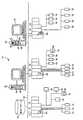
図1を参照すると、スマートプロセスオブジェクトが、プラント環境の中で強化された制御とシミュレーションを提供するために、ともに制御モジュールと統合されてよいプロセスグラフィックディスプレイとプロセスモジュールを形成するために使用されるプロセスプラント例10が詳細に描かれている。特に、プロセスプラント10は、各々が、例えばFieldbusインタフェース、Profibusインタフェース、HARTインタフェース、標準4−20maインタフェース等であってよい1台以上のフィールドデバイス14及び16に入力/出力(I/O)装置またはカード18を介して接続されている、1台以上のコントローラ12を有する分散プロセス制御システムを使用している。コントローラ12は、例えばイーサネット(登録商標)リンクであってよいデータハイウェイ24を介して、1つ以上のホストワークステーションまたはオペレータワークステーション20と22にも結合されている。データベース28はデータハイウェイ24に接続されてよく、パラメータ、ステータス、およびプラント10内のコントローラおよびフィールドデバイスと関連付けられている他のデータを収集し、記憶するデータヒストリアンとして、およびコントローラ12およびフィールドデバイス14と16にダウンロードされ、それらの中に記憶されるようなプラント10の中のプロセス制御システムの現在の構成を記憶する構成データベースとして動作する。コントローラ12、I/Oカード18およびフィールドデバイス14と16は、通常は、場合によってはより厳しいプラント環境の中に位置しおよびプラント環境全体に分散しているが、オペレータワークステーション20と22およびデータベース28は通常コントロールルーム内、あるいはコントローラまたは保守人員が容易に評価できる他のあまり厳しくない環境に配置される。 Referring to FIG. 1, smart process objects are used to form process graphic displays and process modules that may be integrated together with a control module to provide enhanced control and simulation in a plant environment. An
公知のように、一例としてエマーソンプロセスマネジメント(Emerson Process Management)によって販売されているDeltaV(商標)コントローラであってよいコントローラ12の各々は、任意の数の異なった、個別に実行される制御モジュールまたはブロック29を使用して制御戦略を実現するコントローラアプリケーションを記憶し、実行する。制御モジュール29の各々は、一般的に機能ブロックと呼ばれているものから構成することができ、各機能ブロックは全体的な制御ルーチンの一部つまりサブルーチンであり、プロセスプラント10の中でプロセス制御ループを実現するために(リンクと呼ばれる通信を介して)他の機能ブロックと連動して動作する。周知のように、オブジェクト指向プログラミングプロトコル内でオブジェクトであってよい機能ブロックは、通常、送信機、センサ、または他のプロセスパラメータ測定装置と関連付けられているもの等の入力機能、PID、ファジー論理等の制御を実行する制御ルーチンと関連付けられているもの等の制御機能、またはプロセスプラント10内でいくらかの物理的な機能を実行するためにバルブ等の何らかのデバイスの動作を制御する出力機能の内の1つを実行する。言うまでもなく、モデル予測コントローラ(MPC)、オプティマイザ等のハイブリッドタイプおよび他のタイプの複雑な機能ブロックが存在する。FieldbusプロトコルおよびDeltaVシステムプロトコルは、オブジェクト指向プログラミングプロトコルで設計され、実現される制御モジュールと機能ブロックを使用する一方で、制御モジュールは例えば順次機能ブロック、ラダー論理回路等を含む任意の所望の制御プログラミングスキームを使用して設計することができ、機能ブロックまたは任意の他の特定のプログラミング技法を使用して設計され、実現されることに制限されるものではない。 As is known, each of the
図1に描かれているプラント10では、コントローラ12に接続されているフィールドデバイス14と16は標準4−20maデバイスであってよく、プロセッサとメモリを含む、あるいは他の任意の所望のタイプのデバイスであってよい、HART、Profibus、またはFOUNDATION(商標)Fieldbusフィールドデバイス等のスマートフィールドデバイスであってよい。(図1で参照番号16を付与されている)Fieldbusフィールドデバイス等のこれらデバイスのいくつかは、コントローラ12内で実現される制御戦略と関連付けられる、機能ブロック等のモジュールまたはサブモジュールを記憶し、実行してよい。図1にFieldbusデバイス16の2台の異なるデバイスの中に配置されるものとして図1に描かれている機能ブロック30は、周知のようにプロセス制御を実現するためにコントローラ12の中で制御モジュール29の実行と関連して実行されてよい。言うまでもなく、フィールドデバイス14と16はセンサ、バルブ、送信機、ポジショナ等の任意のタイプのデバイスであってよく、I/Oデバイス18はHART、Fieldbus、Profibus等の任意の所望の通信プロトコルまたはコントローラプロトコルに準拠する任意のタイプのI/Oデバイスであってよい。 In the
図1のプロセスプラント10では、ワークステーション20は、プロセスプラント10の中で接続されているデバイス、装置等に関して機能を表示して、提供するために(他のタイプのユーザも存在してよいが、本明細書では構成エンジニアおよびオペレータと呼ばれることもある)任意の許可されたユーザがアクセスできるオペレータインタフェースアプリケーションおよび他のデータ構造32一式を含む。該オペレータインタフェースアプリケーション32一式は、ワークステーション20のメモリ34に記憶され、アプリケーション一式32の中のアプリケーションまたはエンティティの各々はワークステーション20と関連するプロセッサ36で実行されるように適応される。アプリケーション32一式全体がワークステーション20に記憶されているものとして描かれているが、これらのアプリケーションまたは他のエンティティのいくつかはプラント10の中の、またはプラント10に関連付けられた他のワークステーションまたはコンピュータデバイスに記憶され、実行されるであろう。さらに、アプリケーション一式はワークステーション20と関連付けられているディスプレイ画面37に、または携帯端末、ラップトップコンピュータ、他のワークステーション、プリンタ等を含む他の所望のディスプレイ画面またはディスプレイ装置にディスプレイ出力を提供できる。同様に、アプリケーション32一式の中のアプリケーションは分割され、2台以上のコンピュータまたは機械上で実行されてよく、相互に連動して動作するように構成されてよい。 In the
一般的に、アプリケーション32一式によって、3つの異なるタイプのエンティティの作成と使用が可能になり、その動作は、強化された制御機能、シミュレーション機能および表示機能をプロセスプラント10の中で提供するためにともに統合されてよい。より詳細には、アプリケーション32一式は(一般的にはプロセスプラントの一部に関するオペレータディスプレイを提供する)プロセスグラフィックディスプレイ35、(一般的にはプロセスプラントの一部のシミュレーションを提供する)プロセスモジュール39、および一般的にはプロセスのオンライン制御を提供または実行する、制御モジュール29等のプロセス制御モジュールを作成し、実現するために使用されてよい。プロセス制御モジュール29は概して当該技術分野で周知であり、機能ブロック制御モジュール等の任意のタイプの制御モジュールを含んでよい。より詳細に後述されるプロセスグラフィックディスプレイ要素35は、オペレータ等のユーザに、プロセスプラントおよびその中の要素の動作、構成またはセットアップについての情報を提供するために、一般的にはオペレータ、エンジニアまたは他のディスプレイによって使用される要素である。プロセスモジュール39は、通常プロセスグラフィックディスプレイ要素35に密接に結び付けられ、プロセスプラントの、あるいはプロセスグラフィックディスプレイ35に描かれている方法で接続されているその中の異なる要素の動作のシミュレーションを実行するために使用されてよい。プロセスグラフィックディスプレイ35およびプロセスモジュール39は、ラップトップ型コンピュータ、携帯端末等を含む、プロセス制御プラント10に関連付けられている任意の他のコンピュータにダウンロードされ、その中で実行できるであろうが、プロセスグラフィックディスプレイ35およびプロセスモジュール39は、ワークステーション20と22に記憶され、それらによって実行されるものとして描かれている。 In general, the set of
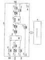
図2は、ワークステーション20のアプリケーション32一式の中のアプリケーションとデータ構造または他のエンティティのいくつかを描いている。特に、アプリケーション32一式は制御モジュール、プロセスモジュール、および制御モジュール、(プロセスフローモジュールとも呼ばれる)プロセスモジュール、および関連グラフィックディスプレイを作成するために構成エンジニアによって使用されるグラフィックディスプレイ構成アプリケーション38を含む。制御モジュール構成アプリケーション38は任意の標準的な、または公知の制御モジュール構成アプリケーションであってよいが、プロセスモジュールおよびグラフィックディスプレイ構成アプリケーションは1つ以上のスマートプロセスオブジェクトを使用してプロセスモジュールおよびグラフィックディスプレイを作成してよく、その性質がより詳細に後述されるであろう。またさらに、プロセスモジュールおよびプロセスグラフィック構成アプリケーション38は個別に示される一方、1つの構成アプリケーションはこれらのタイプの要素の両方ともを作成可能となる。 FIG. 2 depicts some of the applications and data structures or other entities in the set of
スマートプロセスオブジェクト42のライブラリ40は、プロセスモジュール39およびグラフィックディスプレイ35を作成するために構成アプリケーション38によってアクセスされ、コピーされ、使用されてよい実施例またはテンプレートのスマートプロセスオブジェクト42を含む。理解されるように、構成アプリケーション38は、1つ以上のプロセスモジュール39を作成するために使用されてよく、その各々は1つ以上のスマートプロセスオブジェクト42から構成されるあるいは作成され、プロセスモジュールメモリ46に記憶されている1つ以上のプロセスフローまたはシミュレーションアルゴリズム45を含んでよい。さらに、構成アプリケーション38は、1つ以上のグラフィックディスプレイ35を作成するために使用されてよく、その各々は1つ以上のスマートプロセスオブジェクト42から構成される、あるいは作成され、ともに接続されている任意の数のディスプレイ要素を含んでよい。グラフィックディスプレイ35bの内の1つは拡大された形式で図2に描かれており、配管、導管、電力ケーブル、コンベヤ等であってよい接続要素によって相互接続されている、バルブ、タンク、センサおよびフロートランスミッタ等のプロセス要素の集合の描写を含む。 The
実行エンジン48は、グラフィックディスプレイ35によって定義されるようにオペレータ向けの1つ以上のプロセスディスプレイを作成するために、およびプロセスモジュール39と関連付けられるシミュレーション機能を実現するために実行時中にグラフィックディスプレイ35とプロセスモジュール39の各々を操作するまたは実現する。実行エンジン48は、全体をプロセスモジュール39で実現される論理、および特にそれらのモジュールの中のスマートプロセスオブジェクトを定義する規則データベース50を使用してよい。実行エンジン48は、プロセスモジュール39の機能を実現するためにプロセスモジュール39の中のみではなく、プラント10の中でもプロセス要素間の接続を定義する接続マトリクス52も使用してよい。 The
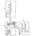
図2は、より詳細にスマートプロセスオブジェクト42eの内の1つを描いている。スマートプロセスオブジェクト42eはテンプレートスマートプロセスオブジェクトの内の1つであるとして描かれているが、他のスマートプロセスオブジェクトが概して、スマートプロセスオブジェクト42eに関して説明されているように、同じ、または類似する要素、特徴、パラメータ等を含むこと、およびこれらの要素、特徴およびパラメータの詳細または値がそのスマートプロセスオブジェクトの性質と用途に応じて、スマートプロセスオブジェクトごとに変更、または変えられてよいことが理解されるであろう。さらに、スマートプロセスオブジェクト42eはオブジェクト指向プログラミング環境の中のオブジェクトであってよく、したがってデータ記憶領域、入力と出力、およびそれと関連付けられるメソッドを含んでよい一方、このスマートプロセスオブジェクトは任意の他の所望のプログラミングパラダイムまたはプロトコルによって作成され、その中で実現されてよい。 FIG. 2 depicts one of the smart process objects 42e in more detail. Although the
理解されるように、インスタンスを作成される前のスマートプロセスオブジェクト42eは、図1のプロセスプラント10の中の物理エンティティまたは論理エンティティ等のある特定のタイプのエンティティと関連付けられているオブジェクトである。しかしながら、コピーされ、インスタンスを作成された後、スマートプロセスオブジェクト42eはプロセスプラントの中のある特定のエンティティに結び付けられてよい。いずれの場合においても、スマートプロセスオブジェクト42eは、スマートプロセスオブジェクト42eが関連づけられている論理エンティティから受信され、あるいは論理エンティティに関するデータを記憶するために使用されるスマートプロセスデータ記憶領域53を含む。データ記憶領域53は、製造メーカ、改訂、名称、種別等の、スマートプロセスオブジェクト42eが関連するエンティティについての一般的な情報または恒久的な情報を記憶するデータ記憶領域53aを含む。データ記憶領域53bは、パラメータデータ、ステータスデータ、入力データと出力データ、コスト、またはそれがプロセスプラント10の中に過去に存在したとき、または現在存在しているときの、エンティティと関連付けられるデータを含む、スマートプロセスオブジェクト42eが関連するエンティティについての他のデータ等の可変データまたは変化するデータを記憶してよい。言うまでもなく、スマートプロセスオブジェクト42eは、任意の所望の通信リンクを介してエンティティ自体から、イーサネット(登録商標)バス24を介してヒストリアン28から、または任意の他の所望の方法で、周期的に、または非周期的にこのデータ(例えばコストデータ)を受信するように構成、あるいはプログラミングされてよい。データ記憶領域53cは、スマートプロセスオブジェクト42eが関連し、図1のワークステーション20と関連付けられている画面37等の、オペレータインタフェースを介してオペレータへの実際のディスプレイのために使用されるエンティティのグラフィック表現を記憶してよい。言うまでもなく、グラフィック表現は、パラメータによって定義される情報、またはデータ記憶領域53bに記憶されるようなエンティティについての他の可変データ等のエンティティについての情報のプレースホルダ(データ記憶領域53c内で下線により記される)を含んでよい。このパラメータデータは、ディスプレイ装置37上でグラフィックディスプレイ35の内の1つの一部としてオペレータに提示されるとき、グラフィックプレースホルダに表示されてよい。グラフィック表現(およびスマートプロセスオブジェクト42e)は、オペレータまたは構成エンジニアが、グラフィック表現によって描かれているように、プロセス要素に上流または下流の構成要素を取り付けることが可能となる(データ記憶領域53cの中で「X」で記される)所定の接続点も含んでよい。言うまでもなく、これらの接続点により、スマートプロセスオブジェクト42eは、プロセスモジュール内で構成されるものとしてそのスマートオブジェクトに接続される要素を認識することも可能となり、配管、ダクト等、その要素等に関連付けられるストリーム等、使用されなければならないひとつのタイプの接続要素を指定してよい。 As will be appreciated, the
スマートプロセスオブジェクト42eは、スマートプロセスオブジェクト42が使用されるプロセスモジュールの内部または外部で他のスマートプロセスオブジェクトとの通信を可能にするために1つ以上の入力54および出力56も含んでよい。他のスマートプロセスオブジェクトへの入力54と出力56の接続は、他のスマートプロセスオブジェクトをこれらの入力と出力に単に接続することにより、あるいはスマートプロセスオブジェクト間で発生しなければならない特定の通信を指定することにより、プロセスモジュールの構成中に構成エンジニアによって構成されてよい。これらの入力と出力のいくつかは、前述されたようにスマートプロセスオブジェクトのための所定の接続ポイントでスマートプロセスオブジェクトに接続されるものとして定義されてよい。これらの入力54と出力56は、規則データベース50内の一式の規則およびプラント10の中の異なるデバイスまたはエンティティの間で接続を定義する接続マトリクス52によって決定または定義されてもよい。それらと関連付けられているデータ記憶領域またはバッファを含む入力54と出力56は、一般的に、他のスマートプロセスオブジェクトからスマートプロセスオブジェクト42eにデータの通信を提供するために、あるいはスマートプロセスオブジェクト42eの中に記憶され、あるいはスマートプロセスオブジェクト42eによって生成されるデータの通信を他のスマートプロセスオブジェクトに提供するために使用される。これらの入力および出力は、スマートプロセスオブジェクト42eと、コントローラ12、フィールドデバイス14、16等の中の制御モジュール等のプロセス制御システム内の他のオブジェクトとの間で通信を提供するために使用されてもよい。 The
図2に描かれているように、スマートプロセスオブジェクト42eは、スマートプロセスオブジェクト42eが使用されるプロセスモジュールの実行中にスマートプロセスオブジェクト42eによって実現されるアルゴリズムであってよい(図2でメソッド60a、60b、および60cとして描かれている)0個、又は1個以上のメソッド60を記憶するために使用されるメソッド記憶領域58も含む。一般的に、メソッド記憶領域58に記憶されているメソッド60は、プロセスプラント10またはプラント10内のエンティティについての情報を突き止めるために、データ記憶部分53aと53bの中に記憶されているデータ、および他のスマートプロセスオブジェクトから取得されるデータ、または入力54と出力56を介して構成データベースまたはヒストリアン28等の他のソースからのデータも使用する。例えば、メソッド60はスマートプロセスオブジェクト42eによって定義されるエンティティと関連付けられる質の低いまたは不良の動作状態、プロセスプラント10の中のそのエンティティまたは他のエンティティと関連付けられるエラー等を決定してよい。メソッド60は、スマートプロセスオブジェクトのタイプまたはクラスに基づいて事前に設定または提供されてよく、毎回スマートプロセスオブジェクト42eが実行時中に実行エンジン48の中で実行されるたびに実行されるであろう。スマートプロセスオブジェクト42e等のスマートプロセスオブジェクトの中で提供されてよいいくつかのメソッド例60は漏れ、デッドバンド、不動作時間、移動、可変、状態監視、コスト計算、またはエンティティと関連付けられる他の状態を検知することを含む。 As depicted in FIG. 2,
メソッド60は、そのプロセスエンティティを通って流れる材料に関してスマートプロセスオブジェクトと関連付けられるプロセスエンティティの動作をシミュレーションする場合に役立つように提供されてよい。このようにして、メソッド60は、要素の動作をシミュレーションし、提供されている入力に基づいて予想出力を計算するために、質量平衡、エネルギーバランス、流量、温度、組成、蒸気状態、およびプラント10の中で材料と関連付けられる他のシステムレベルまたはストリームレベルのパラメータを計算するために提供されてよい。言うまでもなく、これらはスマートプロセスオブジェクト42eに記憶し、それによって実行できるメソッドの内の数個に過ぎず、使用されてよい他の多くのメソッドがあり、このようなメソッドは、通常表現されているエンティティのタイプ、他の要因のみではなく、そのエンティティがプロセスプラント内でどのように接続され、使用されるのかによっても決定されている。スマートプロセスオブジェクト42eがシステムレベルの状態、エラー等を検知するメソッドを記憶し、実行してよい一方、これらのメソッドはプロセス制御モジュールとループ等のデバイス、論理要素、および他の非システムレベルエンティティについての他の情報を決定するために使用されてもよいことに留意することが重要である。所望の場合、メソッド60は、C、C++、C#等の任意の所望のプログラミング言語でプログラミング、または提供されてよいか、あるいは実行中にスマートプロセスオブジェクト42eのために実行されなければならない規則データベース50の中で適用可能な規則を参照し、あるいは適用可能な規則を定義してよい。 A method 60 may be provided to assist in simulating the behavior of a process entity associated with a smart process object with respect to the material flowing through that process entity. In this way, the method 60 simulates the operation of the element and calculates the expected output based on the input provided, mass balance, energy balance, flow rate, temperature, composition, vapor state, and
所望の場合、各スマートプロセスオブジェクトは、プロセスモジュール内で接続される場合にスマートプロセスオブジェクトのシミュレーション動作を定義するために使用されてよい適用可能なアルゴリズムまたはメソッドのライブラリを含んでよい。このようなライブラリは図2のスマートプロセスオブジェクト42eのためのプルダウンメニュー61に描かれており、類似するメニューは各々の他のスマートプロセスオブジェクトと関連付けられてよい。構成エンジニアは、このスマートプロセスオブジェクトが、例えばプルダウンメニュー61を介して(メソッド1、メソッド2等と呼ばれている)シミュレーションアルゴリズムのライブラリの内の1つを選択することによりプロセスモジュール39に格納される場合にスマートプロセスオブジェクトのシミュレーション動作を定義してよい。このようにして、構成エンジニアは、スマートプロセスオブジェクトをモデル化するために使用されているプロセスのタイプまたは性質に依存しているスマートプロセスオブジェクトのために異なるシミュレーション動作を定義してよい。 If desired, each smart process object may include a library of applicable algorithms or methods that may be used to define the simulation behavior of the smart process object when connected within a process module. Such a library is depicted in the pull-down menu 61 for the
所望の場合、構成エンジニアは、代わりに、スマートプロセスブロックによって定義されるプロセス要素のシミュレーション動作を定義するために、独自仕様の、または他のユーザによって供給されるアルゴリズムを提供してよい。(プルダウンメニュー61で「ユーザ定義」エントリとして描かれている)このようなユーザによって定義されたアルゴリズムは、そのスマートプロセスオブジェクトがプロセスモジュール39の中に格納される、あるいはその中で使用される場合にスマートプロセスオブジェクトに提供され、その中に記憶されてよい。この機能により、ユーザはシミュレーション動作をカスタマイズし、それによりさらに優れた、またはさらに正確なシミュレーションを提供できる。所望の場合、およびさらに詳しく後述されるように、スマートプロセスオブジェクト42eまたは各プロセスモジュール39は、スマートプロセスオブジェクト内のシミュレーションアルゴリズムの使用を無効にし、代わりにプロセスモジュールの動作を、HYSYSによって提供されるもの等のハイファイシミュレーションパッケージまたはプログラムによって決定させるオペレータが作動可能な(電子スイッチまたはフラグ等の)スイッチを含んでよい。この場合、スマートプロセスオブジェクトまたはプロセスモジュールは、スマートプロセスオブジェクト自体の中でシミュレーションアルゴリズムを使用することと対照的にハイファイシミュレーションからシミュレーションによるパラメータデータを取得する。 If desired, the configuration engineer may instead provide a proprietary or other user supplied algorithm to define the simulation behavior of the process elements defined by the smart process block. Such a user-defined algorithm (drawn as a “user-defined” entry in pull-down menu 61) is used when the smart process object is stored or used in
グラフィックディスプレイ35またはプロセスモジュール39の実行エンジン48による実行中、エンジン48は、グラフィックディスプレイ35またはプロセスモジュール39内のスマートプロセスオブジェクトの各々に入力54と出力56によって定義される通信を実現し、メソッド60によって提供される機能を実行するために、それらのオブジェクトの各々についてメソッド60を実現してよい。前記に注記されたように、メソッド60の機能はスマートプロセスオブジェクトの中のプログラミングに位置してよいか、あるいはそれらの規則によって定義される機能を実現するために、スマートプロセスオブジェクトのタイプ、クラス、識別、タグ名等に基づいて、エンジン48が実行する規則データベース50内の一式の規則によって定義されてよい。 During execution by the
スマートプロセスオブジェクト42eのインスタンスが、スマートプロセスオブジェクト42eが関連付けられるプロセスモジュールに関してタグまたは一意の名前を有しており、このタグまたは一意の名前がスマートプロセスオブジェクト42eへ、およびスマートプロセスオブジェクト42eから通信を提供するために使用されてよく、実行時中に実行エンジン48によって参照されてよいことが注記される。プロセスモジュールタグは制御システム構成の中で一意でなければならない。このタグ付け規約により、プロセスモジュール39の中の要素は、プロセスグラフィックディスプレイ35、プロセスモジュール39、および制御モジュール29の他の中の要素によっても参照できる。またさらに、スマートプロセスオブジェクト42eのパラメータは単純な値のような単純なパラメータ、構造化されたパラメータ、または予想される装置とそれと関連付けられている属性を認識しているスマートパラメータである場合がある。スマートパラメータは、すべての信号が同じ装置内で送信されている、あるいは適切に変換されていることを保証するために、プロセス規則エンジンまたは実行エンジン48によって解釈、使用できる。スマート規則は、オペレータ向けのスマートアラーム戦略および/またはインタフェースを作成するためにスマートプロセスオブジェクト(またはプロセスモジュール)のためのアラームのグループをオンにしたり、オフにするために使用することもできる。またさらに、スマートプロセスオブジェクトクラスは、スマートプロセスオブジェクトと、それが解釈またはアクセスする必要のあるプロセス変数との間の公知のリンクを提供するために、プラント10のプロセス制御戦略の中で装置とモジュールクラスと関連付けることができる。 An instance of the
スマートプロセスオブジェクトは、プロセスグラフィックディスプレイまたはプロセスモジュールの中で使用されるとき、これらのスマートオブジェクトがオフモード、起動モード、および通常モード等の実行時中の異なるモードにされてよいように動作モード、ステータス、アラーム動作も含んでよく、その現在の動作状態に基づいてオブジェクトと関連付けられるステータスを提供してよく、範囲外、限定、高可変性等のパラメータが検知された状態に基づいてアラームを提供してよい。スマートプロセスオブジェクトは、それらをクラスライブラリで分類する、複合構造でともに収集する等を行うことが可能となるクラス/サブクラス階層も有してよい。さらに、スマートプロセスオブジェクトは、スマートプロセスオブジェクトが、その関連エンティティがいつビジーなのか、あるいは例えばプラント10内でバッチ制御プロセスによっていつ取得されるのかを認識可能とするために、制御モジュールおよび他のオブジェクト等の他の要素からの情報を活用してよい。 When smart process objects are used in a process graphic display or process module, these smart objects can be put into different modes at runtime, such as off mode, start-up mode, and normal mode, It may also include status, alarm action, provide status associated with the object based on its current action state, and provide alarm based on condition detected parameters such as out of range, limitation, high variability You can do it. Smart process objects may also have a class / subclass hierarchy that allows them to be classified in a class library, collected together in a composite structure, and so forth. In addition, smart process objects can be used to identify control process and other objects so that the smart process object can recognize when its associated entity is busy or when it is acquired, for example, by a batch control process within the
スマートプロセスオブジェクトは、ポンプ、タンク、バルブ等の物理デバイス、あるいはプロセス領域、測定、またはアクチュエータ、制御戦略等の論理エンティティ等の任意の所望のプロセスエンティティと関連付けられてよい。いくつかの場合では、スマートプロセスオブジェクトは、コネクタ、このような配管、導管、配線、コンベヤ、あるいは材料、電気、ガス等をプロセスの中のある点から別の点へ移動する任意の他のデバイスまたはエンティティと関連付けられてよい。本明細書ではスマートリンクまたはコネクタ要素と呼ばれることもあるコネクタと関連付けられているスマートプロセスオブジェクトには(実際のデバイスまたはコネクタ自体にタグが付与されていない、あるいはプロセスプラント10内で通信できない場合でも)タグも付与され、一般的にはプロセスの中の他の要素間の材料の流れを表すために使用される。 A smart process object may be associated with any desired process entity, such as a physical device such as a pump, tank, valve, or logical entity such as a process area, measurement, or actuator, control strategy. In some cases, smart process objects are connectors, such pipes, conduits, wires, conveyors, or any other device that moves material, electricity, gas, etc. from one point in the process to another. Or it may be associated with an entity. Smart process objects associated with connectors, sometimes referred to herein as smart links or connector elements (even if the actual device or connector itself is not tagged or cannot communicate within the
スマートリンクは、異なる材料または(電気等の)現象がいかにして接続(例えば、蒸気、電気、水、汚水等)を通って流れるのかを定義する特性またはパラメータを含む。これらのパラメータは、コネクタを通る流れ(一般的な速度、摩擦係数、乱流または非乱流、電磁のような流れのタイプ等)のタイプと性質、およびコネクタを通る流れの考えられる1つ以上の方向を示してよい。スマートリンクは、スマートリンクが接続するソースおよび宛先オブジェクトの単位が一致することを保証するプログラミングまたはメソッドを含んでよく、一致しない場合には変換を実行してよい。スマートリンクのメソッドは、実際のコネクタを通る流れの速度または性質、物理的な接続の長さとサイズ、トランスポート遅延等を推定するためにモデルまたはアルゴリズムを使用してコネクタを通る流れをモデル化してもよい。(摩擦パラメータ等の)スマートプロセスオブジェクトのために記憶されているパラメータはこれらのメソッドで使用されてよい。したがって、本質的には、スマートリンクまたはコネクタ要素は、スマートプロセスオブジェクトが他の上流オブジェクトと下流オブジェクトまたはエンティティを認識できるようにする。スマートリンクが、例えば他のオブジェクトとの間の接続、システム内の液体、ガス、電気等の流体のタイプ、他のエンティティがこのスマートプロセスオブジェクトのエンティティの上流および下流にあるエンティティの上流側と下流側、任意の所望の、または便宜的な材料、流体、電流等の方向を定義してよいことは言うまでもない。一実施形態では、実質的にはプロセスフローモジュールの実行の前にマトリックス52が作成されてよく、プラント内の異なるデバイス間の相互接続をスマートリンクのために、したがって異なるスマートプロセスオブジェクト間の相互接続を定義してよい。つまり、実行エンジン48は上流エンティティと下流エンティティを確定し、それによりスマートプロセスオブジェクトとスマートプロセスオブジェクトとに関連付けられるメソッドの間の通信を定義するためにマトリックス52を使用してよい。またさらに、一式以上の式の規則が、スマートプロセスオブジェクト内のメソッドについて必要に応じて相互に反応し合うため、および必要に応じて相互にデータを取得するためにスマートプロセスオブジェクトによって使用されるために、ならびに出力接続と関連付けられるスマートオブジェクトの影響を解消するために提供されてよい。 Smart links include characteristics or parameters that define how different materials or phenomena (such as electricity) flow through connections (eg, steam, electricity, water, sewage, etc.). These parameters depend on the type and nature of the flow through the connector (general velocity, coefficient of friction, turbulent or non-turbulent, electromagnetic flow type, etc.), and one or more possible flows of the connector. May indicate the direction. The smart link may include programming or methods that ensure that the source and destination object units to which the smart link connects match, and if not, perform a transformation. The smart link method models the flow through the connector using a model or algorithm to estimate the speed or nature of the flow through the actual connector, physical connection length and size, transport delay, etc. Also good. Parameters stored for smart process objects (such as friction parameters) may be used in these methods. Thus, in essence, a smart link or connector element enables smart process objects to recognize other upstream objects and downstream objects or entities. Smart links, for example, connections between other objects, types of fluids in the system, such as liquid, gas, electricity, etc., upstream and downstream of entities where other entities are upstream and downstream of this smart process object entity Of course, the direction of any desired or expedient material, fluid, current, etc. may be defined. In one embodiment, the
所望の場合、スマートプロセスオブジェクト42eは、オブジェクトのタイプに適用可能であってよく、あるいはスマートプロセスオブジェクト42eが関連するデバイスの(臨界および用途に応じて)インスタンスに特化していてよい重要な文書(ドキュメント)に対するURL等のホットリンクも含んでよい。該文書はユーザに特定であってよいだけではなくベンダによって供給されてもよい。文書のいくつかの例は、構成、起動、および停止の手順、操作と保守の文書を含む。所望の場合、オペレータはオブジェクトまたは関連デバイスのためにインスタンスに特化した(存在する場合)総称的な文書を立ち上げるためにオペレータディスプレイに表示されるようにオブジェクトをクリックしてよい。また、オペレータは、システムソフトウェアに関係なく、保守要求、操作上の問題の記録等の文書を追加/削除/変更できることがある。さらに、これらのホットリンクは、オペレータインタフェースの中のオブジェクトに知識リンクを追加する能力を提供するため、オブジェクトに関連する適切な情報への迅速なナビゲーションに備えるため、および顧客に特化したオブジェクトタイプに、またはオブジェクトに特化したインスタンスに特定の作業指示書を追加する能力を提供するために、ユーザによって設定可能または変更可能であってよい。 If desired, the
プロセスモジュールおよびプロセスグラフィックスは異なるスマートプロセスオブジェクトの相互接続によりともに作成されるものとして前述されているが、それらは個別に作成されてよい。例えば、プロセスグラフィックはスマートプロセスオブジェクトを使用して作成されてよく、完了時、そのグラフィックのためのプロセスモジュールはグラフィックディスプレイの中のグラフィック要素およびそれらの相互接続に基づいて生成されてよい。代わりに、プロセスモジュールはスマートプロセスオブジェクトを使用して最初に作成されてよく、いったん作成されると、そのプロセスモジュールのためのグラフィックディスプレイはプロセスモジュールを作成するために使用されるスマートプロセスオブジェクト内のグラフィックディスプレイ要素を使用して構成アプリケーション38によって自動的に生成されてよい。またさらに、プロセスモジュールとグラフィックディスプレイは個別に作成されてよく、これら2つのエンティティの中の個々の要素は相互に参照する(例えば、グラフィックディスプレイとプロセスモジュールの中の要素のタグ特性を使用する)ことにより手動でともに結び付けられてよい。この機構を通じて、スマートプロセスオブジェクトは複数のディスプレイによって参照されてよい。いずれの場合においても、いったん作成されると、プロセスグラフィックディスプレイおよび関連付けられるプロセスモジュールは、それらは所望のようにまたは必要に応じてパラメータと情報を前後に通信するが、無関係にまたは個別に実行されてよい。 Although process modules and process graphics are described above as being created together by the interconnection of different smart process objects, they may be created separately. For example, a process graphic may be created using a smart process object, and upon completion, a process module for that graphic may be generated based on the graphic elements in the graphic display and their interconnections. Instead, a process module may be initially created using a smart process object, and once created, the graphic display for that process module is in the smart process object used to create the process module. It may be automatically generated by the
より包括的には、プロセスグラフィックディスプレイとプロセスモジュール内で、あるいはプロセスグラフィックディスプレイとプロセスモジュールを作成するために使用されてよいスマートプロセスオブジェクトの特定の考えられる機能および例は、より詳細に後述されるであろう。その後、説明される要素と特徴を使用して作成されるプロセスグラフィックディスプレイとプロセスモジュールが高度な制御機能とシミュレーション機能を提供するために制御モジュールとどのように統合されてよいのかが説明される。言うまでもなく、スマートプロセスオブジェクト要素と特徴が本明細書に説明されている要素および特徴に制限されず、他の特徴および要素が、そのように望まれる場合には、プロセスグラフィックディスプレイとプロセスモジュールの内の1つまたは両方の中で使用できる、あるいはプロセスグラフィックディスプレイとプロセスモジュールの内の1つまたは両方を作成するために使用できることが理解されるであろう。 More generally, certain possible functions and examples of smart process objects that may be used within or to create a process graphic display and process module are described in more detail below. Will. It is then described how process graphic displays and process modules created using the described elements and features may be integrated with the control module to provide advanced control and simulation capabilities. Of course, the smart process object elements and features are not limited to the elements and features described herein, and other features and elements may be included in the process graphic display and process module if so desired. It will be appreciated that it can be used in one or both of these, or can be used to create one or both of a process graphic display and a process module.
一般的に、所定のグラフィック要素のセットは、ユーザがプロセスプラントを反映するオペレータディスプレイまたはグラフィックディスプレイを構築可能とするために構成アプリケーションで設けられてよい。これらのグラフィック要素はオンライン測定および制御システムと接続するアクチュエータを動的に示すことを目的とする。さらに、プロセス動作を反映する未測定のパラメータは、プロセスモジュールで提供されるオンラインプロセスシミュレーションを使用して計算されてよく、関連付けられたグラフィックディスプレイの一体化した部分として示されてよい。 In general, a predetermined set of graphic elements may be provided in a configuration application to allow a user to build an operator display or graphic display that reflects the process plant. These graphic elements are intended to dynamically show the actuators that connect to the on-line measurement and control system. Further, unmeasured parameters reflecting process behavior may be calculated using online process simulation provided in the process module and may be shown as an integral part of the associated graphic display.
さらに、エンジニアリングまたはトレーニングシミュレーションのために使用されるオフライン環境では、プロセスモジュールによって提供されるプロセスシミュレーションは、グラフィック要素の中のプロセス測定値の代わりに、および関連付けられた制御モジュールの中で使用されてよい。関連付けられたプロセスモジュールによって計算されるこれらの値は、プロセスグラフィックスに描かれている手動外乱値のみではなくアクチュエータ位置または状態にも基づいてよい。このようにして、グラフィックディスプレイと制御モジュールは、オンライン、つまり制御状況と、オフライン、つまりシミュレーション状況の両方で使用されてよい。また、グラフィック要素の静的な部分は多くの場合では公知のグラフィックライブラリに含まれている三次元成分と同様に表示されるが、これらのグラフィック要素の追加の一意の特徴または特性、これらの要素とともに表示される情報、および制御システムI/Oおよびプロセスシミュレーションモジュールへのリンクは、多くのグラフィック要素の考えられるタイプと例に関して前述されている。 In addition, in the offline environment used for engineering or training simulation, the process simulation provided by the process module is used in place of the process measurements in the graphic elements and in the associated control module Good. These values calculated by the associated process module may be based not only on the manual disturbance values depicted in the process graphics, but also on the actuator position or state. In this way, the graphic display and the control module may be used both online, i.e. in a control situation and offline, i.e. in a simulation situation. Also, the static parts of graphic elements are often displayed in the same way as the three-dimensional components contained in known graphic libraries, but the additional unique features or characteristics of these graphic elements, these elements Information displayed along with and links to control system I / O and process simulation modules are described above with respect to possible types and examples of many graphic elements.
一般的に、スマートプロセスオブジェクトと関連付けられるプロセスモジュールの中のグラフィック要素とシミュレーションアルゴリズムは、ストリーム要素、プロセス接続要素、アクチュエータ要素、処理要素、測定要素および推定特性要素を含む多くの異なるタイプのプロセス要素の内の1つに該当する。一般的に、ストリーム要素はプロセスプラント内での材料のストリームを定義し、組成、密度、流量、温度、圧力、重量、および/または該材料の流れを定義する任意の他のパラメータを示すためにグラフィックディスプレイに露呈されてよい。ストリーム要素はプロセスモジュールの入力時に定義され、プロセスモジュールの中の要素に提供され、それによりプロセスモジュールを通過する材料のストリームをモデル化し、グラフィックディスプレイに描くことをできるようにしてよい。同様に、ストリーム要素は、グラフィックディスプレイの中で、グラフィックディスプレイにより描かれるプロセスプラントの部分の材料出力を描くためにプロセスモジュールの出力時または最後に描かれてよい。ストリーム要素は、異なるグラフィックディスプレイ(および関連プロセスモジュール)が相互にいかにして接続しているのかを定義するためにも使用されてよい。例えば、あるプロセスモジュールの出力ストリームは別のプロセスモジュールの入力ストリームであってよく、他のプロセスモジュールの入力ストリームで使用される値を指定してよい。ストリームは以下の4つの部分、つまり(pHストリーム等の)名前、(流れ入力等の)方向、(流量、圧力、温度等の)測定値、および(窒素、アンモニア等の)組成を含んでよい。ただし、ストリームはそのように所望の場合他のパーツまたはパラメータを有することができるであろう。 In general, the graphic elements and simulation algorithms in process modules associated with smart process objects are many different types of process elements including stream elements, process connection elements, actuator elements, processing elements, measurement elements and estimated characteristic elements. It corresponds to one of these. In general, a stream element defines a stream of material within a process plant to indicate composition, density, flow rate, temperature, pressure, weight, and / or any other parameter that defines the flow of the material. It may be exposed on a graphic display. Stream elements may be defined at the input of a process module and provided to elements in the process module so that a stream of material passing through the process module can be modeled and drawn on a graphic display. Similarly, stream elements may be drawn at the end of the process module or at the end to draw the material output of the portion of the process plant drawn by the graphic display within the graphic display. Stream elements may also be used to define how different graphic displays (and associated process modules) are connected to each other. For example, an output stream of one process module may be an input stream of another process module, and a value used in an input stream of another process module may be specified. The stream may include the following four parts: name (such as pH stream), direction (such as flow input), measurement (such as flow, pressure, temperature), and composition (such as nitrogen, ammonia). . However, the stream could have other parts or parameters if so desired.
プロセス接続要素は、固形物、液体または蒸気、および気体等のプラントの内の物質があるデバイスから別のデバイスへいかにして送達または搬送されるのかを定義する。プロセスを通過する材料の流れを明確に描くために、パイプ、ダクト、およびコンベヤを含む三種類の異なったタイプのプロセス接続が使用されてよい。電気化学プロセス等における電力潮流をアドレス指定するための電気ケーブル等の他の接続要素も使用されてよいことは言うまでもない。配管は、通常、液体および高圧蒸気またはプラント内での気体の流れを描くために使用される。一般的にダクトはプラント内の低圧ガスの流れを描く(そしてシミュレーションする)ために使用される。一般的にコンベヤは処理装置間での固形物の移動を描く(そしてシミュレーションする)ために使用される。その結果として、各プロセス接続要素は、デバイスの入力または出力時に材料を提供するために使用されるパイプ接続、ダクト接続、またはコンベヤ接続等の接続のタイプを定義する。 Process connection elements define how materials within a plant, such as solids, liquids or vapors, and gases, are delivered or transported from one device to another. Three different types of process connections may be used to clearly depict the flow of material through the process, including pipes, ducts, and conveyors. Of course, other connection elements such as electrical cables for addressing power flow in electrochemical processes and the like may also be used. Piping is typically used to depict the flow of liquids and high pressure steam or gases within a plant. In general, ducts are used to depict (and simulate) the flow of low pressure gas in a plant. Generally, conveyors are used to depict (and simulate) the movement of solids between processing equipment. As a result, each process connection element defines the type of connection, such as a pipe connection, duct connection, or conveyor connection, that is used to provide material at the input or output of the device.
所望の場合、接続により移送されている材料の特性は上流入力により決定される。接続が完了したか否かを定義する接続ステータス変数が加えられるこの情報は、グラフィックディスプレイ上で接続要素の特性として利用できるようにされてよい。接続要素は処理要素出力、アクチュエータ要素出力またはストリーム要素出力で開始してよい。同様に、接続要素は処理要素入力、アクチュエータ要素入力またはストリーム入力時に終了してよい。 If desired, the properties of the material being transferred by the connection are determined by the upstream input. This information, to which a connection status variable defining whether or not the connection is completed, is added and may be made available as a characteristic of the connection element on the graphic display. The connecting element may start with a processing element output, an actuator element output or a stream element output. Similarly, a connection element may terminate upon processing element input, actuator element input or stream input.
接続要素の特性は、カーソルがグラフィックディスプレイの接続要素上に置かれると自動的に表示されてよい。また、接続要素と関連付けられている特性は接続要素の上に(下記に定義される)測定要素または推定特性要素を置くことにより恒久的なディスプレイに表示されてよい。所望の場合、接続要素は(ストリーム出力、処理要素出力またはアクチュエータ要素出力等の)要素出力上で左マウスボタンを押し続け、マウスのボタンを押し続ける間にカーソルを要素入力上に配置することにより作成されてよい。接続が無事に確立されるために、上流要素と下流要素の入力タイプと出力タイプ(パイプ、ダクト、またはコンベヤ)は一致しなければならない。接続は上流要素のタイプを自動的に取る。 The characteristics of the connection element may be automatically displayed when the cursor is placed on the connection element of the graphic display. Also, the characteristics associated with the connection element may be displayed on a permanent display by placing a measurement element or estimated characteristic element (defined below) on the connection element. If desired, the connecting element keeps pressing the left mouse button on the element output (such as stream output, processing element output or actuator element output) and placing the cursor on the element input while holding down the mouse button May be created. In order for the connection to be established successfully, the input type and output type (pipe, duct, or conveyor) of the upstream and downstream elements must match. The connection automatically takes the type of upstream element.
所望の場合、配管要素はパイプ接続のようなプロセスグラフィックディスプレイに示され、または描くことができ、ダクト要素(例えば空気またはガス)はダクトとして示すことができ、コンベヤ要素はコンベヤベルトとして示されてよい。配管要素、ダクト要素およびコンベヤ要素の接続は、処理要素の間で自動的に経路を定義することができ、矢印は流れの方向を示すためにこれらの要素の描写の外部に表示されてよい。上流出力が2つの接続に共通である場合には、「T」個の要素はパイプ、ダクト、またはコンベヤの中に含まれてよい。「T」個の要素は複数の出力を結合するために使用されてよい。コンベヤ要素の色または他のグラフィック特性は、運転中/停止中、流れている/流れていない、詰まっている等のそのステータスを示すために変化してよい。一般的に、コンベヤに沿った材料の流れはコンベヤに接続されているモータ駆動により決定される。したがって(より詳細に後述されるアクチュエータ要素である)モータ駆動アクチュエータはコンベヤに接続されてよい。さらに、(後述される)測定要素は、コンベヤあるいはパイプまたはダクト内の材料の速度、水分または重量等のコンベヤ、パイプまたはダクト上またはコンベヤ、パイプ、またはダクト内の材料の特性のパイプ要素、ダクト要素またはコンベヤ要素に関連する測定値を表示可能とするためにパイプ要素、ダクト要素およびコンベヤ要素に接続できる。また、表示された特性要素は、例えば材料の組成等の測定されていないパイプ、ダクト、またはコンベヤ上、またはパイプ、ダクトまたはコンベヤ内の材料の特性を表示するために追加されてもよい。 If desired, the piping elements can be shown or depicted in a process graphic display such as a pipe connection, the duct elements (eg air or gas) can be shown as ducts, and the conveyor elements can be shown as conveyor belts. Good. Connections of plumbing elements, duct elements and conveyor elements can automatically define paths between processing elements, and arrows may be displayed outside of these element representations to indicate the direction of flow. If the upstream output is common to the two connections, “T” elements may be included in the pipe, duct, or conveyor. “T” elements may be used to combine multiple outputs. The color or other graphic characteristic of the conveyor element may change to indicate its status, such as running / stopped, flowing / not flowing, clogged, etc. Generally, the material flow along the conveyor is determined by a motor drive connected to the conveyor. Accordingly, a motor driven actuator (which is an actuator element described in more detail below) may be connected to the conveyor. In addition, the measuring element (described below) can be a conveyor, a material such as the speed of material in a pipe or duct, moisture or weight, a pipe element of a material on the conveyor or pipe or duct or a material of the material in the duct, duct It can be connected to pipe elements, duct elements and conveyor elements in order to be able to display the measurement values associated with the elements or conveyor elements. Also, the displayed property element may be added to display a property of the material on or within the pipe, duct, or conveyor that has not been measured, such as the composition of the material.
所望の場合、配管接続要素、ダクト接続要素およびコンベヤ接続要素は、(例えば色の変化により)接続が失われたこと、および(例えば色の変化により)選択された特性(圧力、温度、長さ等)が構成された制限外にある旨をグラフィックに且つ動的に反映してよい。さらに、関連プロセスモジュールによって計算されるパラメータはグラフィックに表示されてよい。例えば、上流接続により提供される特性は、接続のステータスが不良であるのか、あるいは良好であるのかに関係なく、接続要素等の1つ以上の選択されたパラメータを制限し、接続要素により移送されている接続要素またはストリームについてオペレータに情報を与えるためにグラフィックディスプレイに表示されてよい。 If desired, pipe connection elements, duct connection elements and conveyor connection elements may have lost connection (eg due to color change) and selected characteristics (eg due to color change) (pressure, temperature, length) Etc.) may be graphically and dynamically reflected to the extent that they are outside the configured limits. Furthermore, the parameters calculated by the relevant process module may be displayed graphically. For example, the characteristics provided by the upstream connection limit one or more selected parameters, such as the connection element, and are transported by the connection element, regardless of whether the connection status is bad or good. It may be displayed on a graphic display to inform the operator about the connected element or stream.
一般的に、アクチュエータ要素とは、ストリームに関して何らかの作動機能を実行し、異なる接続要素間、または処理要素と接続要素の間に置かれてよい要素である。アクチュエータ要素の例は、(アクチュエータ付き)調整弁、(アクチュエータ付き)開閉弁、(モータ付き)ポンプ、(モータ付き)強制通風ファン、(モータ付き)誘引通風ファン、(開閉弁付き)エダクタ、(ドライブ付き)ダンパ、(可変速度モータ付き)フィーダ、(コンベヤ要素に取り付けられてよい)コンベヤモータドライブ等を含む。 In general, an actuator element is an element that performs some actuation function on the stream and may be placed between different connection elements or between a processing element and a connection element. Examples of actuator elements include: regulator valve (with actuator), on / off valve (with actuator), pump (with motor), forced draft fan (with motor), induction draft fan (with motor), eductor (with on-off valve), ( Includes dampers (with drives), feeders (with variable speed motors), conveyor motor drives (which may be attached to conveyor elements), and the like.
バルブ要素のグラフィック描写は、(例えば、動画による)目に見えないバルブ位置、(例えば、色の変化による)バルブの故障、(例えば、色の変化による)バルブ完全開放/閉鎖位置、およびそのバルブを制御している関連制御ブロックの(数字列または他の表示による)AO、DO、DC、設定点、PV、OUT、モード等を動的に反映してよい。(プロセスモジュールで使用される)バルブ要素と関連付けられているシミュレーション要素は、吐き出し圧力、質量流、液体温度、液組成、入口圧力および出口圧力等のバルブアクチュエータと関連するパラメータを計算するシミュレーションアルゴリズムを有してよい。これらのシミュレーションによる、または計算されたパラメータは、そのように所望の場合、プロセスグラフィックに表示されてよい。ただし、ユーザまたは構成エンジニアは、通常、バルブタイプ(線形、早開き、等しい割合、バルブサイズ等)と開から閉へのストローク時間のみではなく、バルブと関連する制御モジュール内のAOブロック、DOブロックまたはDCブロックに対する参照も設定しなければならない。言うまでもなくバルブを通る材料でのバルブの動作をシミュレーションするために使用可能なシミュレーションアルゴリズムは、バルブの種別とサイズ情報に依存してよい。 Graphic representations of valve elements include invisible valve position (eg, due to animation), valve failure (eg, due to color change), valve fully open / closed position (eg, due to color change), and the valve AO, DO, DC, set point, PV, OUT, mode, etc. of the associated control block that controls (by a numeric string or other display) may be dynamically reflected. Simulation elements associated with valve elements (used in process modules) are simulation algorithms that calculate parameters related to valve actuators such as discharge pressure, mass flow, liquid temperature, liquid composition, inlet pressure and outlet pressure. You may have. These simulated or calculated parameters may be displayed in the process graphic if so desired. However, the user or configuration engineer typically does not only determine the valve type (linear, fast open, equal proportion, valve size, etc.) and the stroke time from open to close, but also the AO block and DO block in the control module associated with the valve. Or a reference to the DC block must also be set. Of course, the simulation algorithms that can be used to simulate the operation of the valve with the material passing through the valve may depend on the type and size information of the valve.
ポンプ要素のグラフィック描写は(例えば色の変化を使用して)モータステータス、(例えば、文字列を使用して)関連DOまたはDC機能ブロックモードと設定点、(可変速度ドライブが使用されている場合には)モータ速度、AO設定点、PV、(可変速度ドライブが使用されている場合には)OUTモード、および他の所望のパラメータを動的に反映してよい。同様に、この要素のための(プロセスモジュールで使用される)プロセスシミュレーションは、吐き出し圧力、液組成、液体温度、および質量流等のパラメータを決定する、または計算してよく、そのパラメータはグラフィックディスプレイに表示されてよい。ユーザはポンプタイプに基づいてポンプ曲線を定義する必要がある場合がある。しかしながら、ユーザはモータ起動/停止に関連するDOブロックまたはDCブロックに対する参照、(使用されている場合)可変速度ドライブのための関連AO機能ブロックに対する参照、およびポンプの動作の定義のためのポンプ曲線(例えば圧力対流量)を設定してよい。 Graphic depiction of pump element (eg using color change) motor status, associated DO or DC function block mode and set point (eg using string), if variable speed drive is used May dynamically reflect motor speed, AO set point, PV, OUT mode (if variable speed drive is used), and other desired parameters. Similarly, the process simulation (used in the process module) for this element may determine or calculate parameters such as discharge pressure, liquid composition, liquid temperature, and mass flow, which are graphical displays. May be displayed. The user may need to define a pump curve based on the pump type. However, the user has a reference to the DO block or DC block related to motor start / stop, a reference to the relevant AO function block for variable speed drives (if used), and a pump curve for defining pump operation (Eg pressure versus flow) may be set.
強制通風ファンまたは誘引通風ファンのアクチュエータ要素のグラフィック描写は、モータステータス、DO機能ブロックモードまたはDC機能ブロックモードと設定点、(可変速度ドライブが使用されている場合には)モータ速度、(可変速度ドライブが使用される場合)AO設定点、PV、OUT、DOまたはDC機能ブロックモード、および他の所望のパラメータを動的に反映してよい描写を有してよく、その内のいずれかがグラフィック描写に表示されてよい。この要素のための(プロセスモジュールで使用される)プロセスシミュレーション要素は、吐き出し圧力、ガス組成、ガス温度、およびガス質量流等のパラメータを決定または計算してよく、そのパラメータはグラフィックディスプレイに表示されてよい。ユーザはモータ起動/停止のための関連DCブロックに対する参照、(使用されている場合)可変速度ドライブのためのAOブロックに対する参照、およびファンのシミュレーションされる動作を定義するためのファン曲線(圧力対流量)を設定してよい。 The graphic depiction of the actuator element of the forced draft fan or the induced draft fan is motor status, DO function block mode or DC function block mode and set point, motor speed (if variable speed drive is used), (variable speed) (If the drive is used) AO setpoint, PV, OUT, DO or DC function block mode, and may have a depiction that may dynamically reflect other desired parameters, any of which are graphic May be displayed in the depiction. The process simulation element (used in the process module) for this element may determine or calculate parameters such as discharge pressure, gas composition, gas temperature, and gas mass flow, which are displayed on a graphic display. It's okay. The user can refer to the relevant DC block for motor start / stop, a reference to the AO block for variable speed drive (if used), and a fan curve (pressure vs. pressure) to define the simulated behavior of the fan. Flow rate) may be set.
いくつかの場合、特定のタイプのアクチュエータは、パイプ、ダクト、またはコンベヤ等の特定のタイプの接続にのみ使用されてよい。以下の表は典型的なアクチュエータ要素の接続制限例を定義する。 In some cases, a particular type of actuator may only be used for a particular type of connection, such as a pipe, duct, or conveyor. The following table defines examples of connection limits for typical actuator elements.

処理要素はいくつかの方法でプラント内で材料またはストリームを処理するプラント装置を含む。一般的に、処理要素に対する、および処理要素からのすべての入力と出力は接続要素を介して行われる。標準処理要素はタンク(縦型と横型)、ヒータ、スタティックミキサー、リアクタ、ミキサー、エアヒータ、および単純な処理活動または標準的な処理活動を実行する他の要素を含む。ユーザは、サイズ、体積等、物理的な装置特性とともに要素に対する入力と出力の数を指定してよい。これらの標準的な処理要素のシミュレーションアルゴリズムおよび静的表現は、それらがユーザによって修正できないように設定されてよいが、前述されたように設定時に選択可能であってよい。所望の場合に、他の、(蒸留塔、エバポレータ、セパレータ、ボイラ等の)通常はさらに複雑なプラント装置がカスタム処理要素として実現されてよいことは言うまでもない。静的表現、このようなカスタム処理要素の入出力数とシミュレーションアルゴリズムは、ユーザインタフェース要件を満たすために修正されてよい。カスタム処理要素はいったん定義されると、他の処理要素の作成において開始点として再利用または使用されてよい合成物またはテンプレートとして保存されてよい。 The processing elements include plant equipment that processes the material or stream within the plant in several ways. In general, all inputs and outputs to and from the processing elements are made via connection elements. Standard processing elements include tanks (vertical and horizontal), heaters, static mixers, reactors, mixers, air heaters, and other elements that perform simple processing activities or standard processing activities. The user may specify the number of inputs and outputs for an element along with physical device characteristics such as size, volume, etc. The simulation algorithms and static representations of these standard processing elements may be set so that they cannot be modified by the user, but may be selectable at setup time as described above. It goes without saying that other, usually more complex plant equipment (such as distillation columns, evaporators, separators, boilers, etc.) may be realized as custom processing elements if desired. The static representation, the number of inputs and outputs of such custom processing elements and the simulation algorithm may be modified to meet user interface requirements. Once defined, custom processing elements may be saved as a composite or template that may be reused or used as a starting point in the creation of other processing elements.
タンク標準処理要素は、タンクに対するパイプ接続に基づいて設定されてよく、タンク要素は(例えば、動的なアニメーションを使用して)タンク内の水位、および(例えば、色の変化を使用して)100%また空の水位を動的に反映してよい。タンクのためのプロセスモジュールシミュレーションは、グラフィックディスプレイを介して、出口温度、出口組成、液体温度およびシミュレーションによるタンクの水位等のパラメータを計算し、表示してよい。しかしながら、システムにタンクを結び付けるために、ユーザまたは構成エンジニアは、入出力接続数、タンクに対する完全な接続、(例えば、直径と高さ等の)サイズなどのタンク特性等を設定する必要がある場合がある。 The tank standard processing element may be set based on the pipe connection to the tank, the tank element (eg using dynamic animation) and the water level in the tank, and (eg using color change) 100% or empty water level may be dynamically reflected. The process module simulation for the tank may calculate and display parameters such as outlet temperature, outlet composition, liquid temperature and simulated tank level via a graphic display. However, in order to tie the tank to the system, the user or configuration engineer needs to set the number of input / output connections, complete connections to the tank, tank characteristics such as size (eg diameter and height), etc. There is.
ヒータ処理要素は、グラフィックディスプレイを介して、(例えば、色の変化を使用して)熱伝達率、出口製品温度、入口製品温度、(安定した低下を想定する)出口圧力等を動的に計算し、反映してよい。ユーザまたは構成エンジニアは、ヒータに対する完全な接続、ヒータ表面積、およびクリーンな状態での熱伝達率を設定する必要がある場合がある。 Heater processing element dynamically calculates heat transfer rate, outlet product temperature, inlet product temperature, outlet pressure (assuming steady drop), etc. (eg using color change) via graphic display And may be reflected. The user or configuration engineer may need to set the perfect connection to the heater, the heater surface area, and the heat transfer rate in a clean state.
言うまでもなく、スタティックミキサー、リアクタ、ミキサー、エアヒータ、熱交換器等の他の処理要素は、これらのタイプのデバイスに調整される表示機能およびシミュレーション機能を有してよい。蒸留塔、エバポレータ、セパレータ、ボイラ等の非標準的な処理要素は、容器に関連付けられたシミュレーションが、標準的な選択に含まれていない場合にはユーザ定義であってよいカスタム処理要素を使用してグラフィックに表現されてよい。これらの要素における処理は、容器の各入力を各出力に関連付けるステップ応答モデルとして記述または定義されてよい。入力は、ガスおよび/または液体のストリームであってよい。任意選択的に、ユーザは処理要素の入力と出力の関係性を記述する方程式を定義してよく、これらの方程式はシミュレーションを実行するために要素を使用してプロセスモジュールに記憶されてよい。所望の場合、いくつかの単純な静的グラフ表現は、ユーザがカスタム処理要素と関連する静的グラフィックを迅速に作成する場合に役立つように提供されてよい。これらの単純なグラフィックが使用される場合には、ユーザは入出力接続の所望の数、およびカスタム処理要素によってサポートされている(パイプ、ダクト、コンベヤ等の)サポート接続のタイプだけを指定する必要がある場合がある。それに応じて、グラフィックアイテムが表示され、オペレータグラフィックの作成で即座に使用できる。所望の場合、プロセス要素の各入力と各出力と関連付けられる利得およびあらゆるダイナミクス(動的状態)は、ユーザがシミュレーションアルゴリズムをステップ応答として指定することを選ぶ場合に指定されてよい。ユーザはカスタムアルゴリズムを選択する場合、シミュレーションアルゴリズムを定義するためにユーザに表現エディタが与えられてよい。選択された方法に基づき、カスタム処理要素出力の特性は異なって計算されてよい。さらに、ユーザは個別のソフトウェアアセンブリで定義したアルゴリズムの1つ以上を参照してよい。 Of course, other processing elements such as static mixers, reactors, mixers, air heaters, heat exchangers, etc. may have display and simulation capabilities tailored to these types of devices. Non-standard processing elements such as distillation columns, evaporators, separators, boilers, etc. use custom processing elements that may be user defined if the simulation associated with the vessel is not included in the standard selection. And may be represented graphically. The processing in these elements may be described or defined as a step response model that associates each input of the container with each output. The input may be a gas and / or liquid stream. Optionally, the user may define equations describing the relationship between the input and output of the processing elements, and these equations may be stored in the process module using the elements to perform the simulation. If desired, some simple static graph representations may be provided to assist users in quickly creating static graphics associated with custom processing elements. When these simple graphics are used, the user only needs to specify the desired number of input / output connections and the type of support connection (pipe, duct, conveyor, etc.) supported by the custom processing element. There may be. In response, graphic items are displayed and can be used immediately in the creation of operator graphics. If desired, the gain and any dynamics (dynamic state) associated with each input and each output of the process element may be specified if the user chooses to specify the simulation algorithm as a step response. If the user selects a custom algorithm, the user may be given a representation editor to define the simulation algorithm. Based on the method selected, the characteristics of the custom processing element output may be calculated differently. In addition, the user may reference one or more of the algorithms defined in the individual software assembly.
さらに、複数の所定の合成物またはテンプレートがカスタム処理要素を作成するために提供されてよい。これらのテンプレートは、例えば、出口ガスO2、出口ガスCO、生成
ストリーム、ボイラドラム水位、およびボイラ通風を計算するカスタムアルゴリズムを有するボイラテンプレートを含んでよい。このようなテンプレートは、単一の燃料入力に基づいてよい。しかしながら、テンプレートを修正することにより、複数の燃料でボイラをシミュレーションできる。他の所定のテンプレートは、噴霧乾燥機カスタム処理要素と連動して使用されてよく、セパレータの動作をモデル化するためにステップ応答モデルを含んでよい専用の容器−サイクロンセパレータテンプレートを含んでよい。同様に、コラムテンプレート、噴霧乾燥機、およびエバポレータ本体は、予想プロセス応答を定義するためにステップ応答モデルを活用してよい。エバポレータでは、エネルギー入力および入力流量の濃度に基づいて、出口流量と蒸気放出の濃度が計算できる。複数のエバポレータ要素は、多重効用蒸発器を作成するために熱交換器とエダクタの要素とともに接続されてよい。同様に、専用の容器スタックカスタムテンプレート処理要素はボイラ処理要素とともに使用されてよい。この場合、入口の特性は、そのように所望の場合、修正を行わずに、あるいはスタック内で実行されるエミッション削減を反映するためにスタックを通して持続されてよい。In addition, a plurality of predetermined composites or templates may be provided for creating custom processing elements. These templates, for example, exit gas O2, the outlet gas CO, product stream may comprise a boiler template having a custom algorithm that calculates the boiler drum level and the boiler draft. Such a template may be based on a single fuel input. However, the boiler can be simulated with a plurality of fuels by modifying the template. Other predefined templates may be used in conjunction with the spray dryer custom processing element and may include a dedicated container-cyclone separator template that may include a step response model to model separator operation. Similarly, column templates, spray dryers, and evaporator bodies may utilize a step response model to define the expected process response. In the evaporator, the outlet flow rate and the vapor discharge concentration can be calculated based on the energy input and the concentration of the input flow rate. A plurality of evaporator elements may be connected with the heat exchanger and eductor elements to create a multi-effect evaporator. Similarly, a dedicated container stack custom template processing element may be used with a boiler processing element. In this case, the inlet characteristics may be persisted through the stack, if so desired, without modification or to reflect emission reductions performed within the stack.
グラフィックディスプレイとプロセスモジュールを作成するために使用できる他のタイプの要素は、測定要素と特性(プロパティ)要素とを含む。測定要素は、物理的な送信機と関連付けられる測定値にアクセスするためにグラフィックディスプレイで使用されてよい送信機要素、およびスイッチ要素を含む。一般的に、送信機要素は、不良ステータスまたは不確実なステータス、制御モジュールの中で関連付けられたAI機能ブロックのモード、実際の送信機(センサ)と関連付けられた測定値と測定装置等、あるいは実際の送信機と関連付けられた他のデータを動的に反映してよい。オフラインモード(またはシミュレーションモード)では、送信機要素は、AIブロックまたはPCIブロックと関連付けられた値より、むしろプロセスモジュールによって提供されるシミュレーション値にアクセスし、表示するために使用されてよいか、あるいはシミュレーションによる制御ルーチンで使用される測定値として制御ブロック内の関連AIブロックに測定値を提供するために使用されてよい。送信機要素は、接続要素に、または処理要素に追加することができ、このような送信機要素がディスプレイに追加されるとき、ユーザは概して、測定値を提供しているコントローラスキームで関連付けられたAIブロック、PCIブロック、またはDIブロックを特定する必要があるであろう。オンラインモードでは、測定の値はこの測定要素の隣に示されてよい。オフラインモード(つまりシミュレーションモード)では、(対応するプロセスモジュールにより作成されるような)測定のシミュレーションされる値が自動的に表示されてよい。オンライン動作では、ユーザは測定が失敗した場合にシミュレーションによる値に制御とディスプレイを切り替えることを選ぶことができる。 Other types of elements that can be used to create graphic displays and process modules include measurement elements and property elements. Measurement elements include a transmitter element that may be used in a graphic display to access measurements associated with a physical transmitter, and a switch element. In general, the transmitter element is a bad or uncertain status, the mode of the AI function block associated in the control module, the measured value and measuring device associated with the actual transmitter (sensor), etc., or Other data associated with the actual transmitter may be dynamically reflected. In offline mode (or simulation mode), the transmitter element may be used to access and display simulation values provided by the process module rather than the values associated with the AI block or PCI block, or It may be used to provide a measurement value to an associated AI block in the control block as a measurement value to be used in a simulated control routine. A transmitter element can be added to the connection element or to the processing element, and when such a transmitter element is added to the display, the user is generally associated with a controller scheme that is providing measurements. It may be necessary to specify an AI block, PCI block, or DI block. In online mode, the value of the measurement may be shown next to this measurement element. In offline mode (ie, simulation mode), the simulated value of the measurement (as created by the corresponding process module) may be automatically displayed. In online operation, the user can choose to switch the control and display to a simulated value if the measurement fails.
スイッチ要素は、不良ステータスまたは不確実なステータス、関連DI(例えば手動またはOS)のモード、およびスイッチの離散値(オン、オフ等)を動的に反映してよい。オフラインシミュレーションモードにある間、ユーザは、シミュレーション値または手動値およびステータスを選択することにより、およびスイッチの値とステータスを手動で入力することによりグラフィックディスプレイおよび制御モジュールのスイッチパラメータにアクセスし、変更するためにスイッチディスプレイを使用してよい。しかしながら、一般的に、ユーザは、制御スキームで関連DIブロックに対する参照、スイッチをトリガする要素特性に対する参照、およびスイッチの状態の変化に関連付けられた制限とデッドバンドを提供することによりスイッチ要素を設定しなければならない。 The switch element may dynamically reflect the bad or uncertain status, the mode of the associated DI (eg manual or OS), and the discrete value of the switch (on, off, etc.). While in offline simulation mode, the user accesses and changes the switch parameters of the graphic display and control module by selecting simulation values or manual values and status, and manually entering switch values and status A switch display may be used for this purpose. In general, however, the user configures the switch element by providing a reference to the associated DI block in the control scheme, a reference to the element property that triggers the switch, and limits and deadbands associated with changes in the state of the switch. Must.
推定される特性要素は、一般的にはプロセスモジュールにより決定されるようなシステムの推定特性を表示し、その要素の任意の特性を表示するために接続または処理要素に追加されてよい。この要素が接続要素に、または1台の装置に置かれると、ユーザは表示される特性をブラウズし、選択できる。したがって、物理的な測定によって入手できないシミュレーション特性は、推定特性要素を使用することにより表示されてよい。このような推定特性要素は、良好/不良な接続、推定特性値(複数の場合がある)および関連範囲または変化の範囲外にある特性を動的に反映してよい。一般的に、ユーザは表示される特性(複数の場合がある)に対する参照、および該特性が範囲外にある場合に要素の範囲と色変化を設定しなければならない。 The estimated characteristic element generally displays the estimated characteristic of the system as determined by the process module and may be added to the connection or processing element to display any characteristic of that element. When this element is placed on a connection element or on a single device, the user can browse and select the properties to be displayed. Thus, simulation characteristics that are not available through physical measurements may be displayed by using estimated characteristic elements. Such estimated characteristic elements may dynamically reflect good / bad connections, estimated characteristic value (s) and characteristics that are outside the relevant range or range of change. In general, the user must set a reference to the characteristic (s) to be displayed and the range and color change of the element if the characteristic is out of range.
理解されるように、送信機要素および推定特性要素を処理要素、アクチュエータ要素、および接続要素に取り付けることにより、これらのプロセス要素の入出力に関連付けられていた特性はオンライン動作またはオフラインシミュレーションの間に参照されてよい。これらの特性はグラフィックディスプレイで可視になってもよい。 As will be appreciated, by attaching transmitter elements and estimated characteristic elements to processing elements, actuator elements, and connection elements, the characteristics associated with the inputs and outputs of these process elements can be determined during online operation or offline simulation. Reference may be made. These characteristics may be visible on a graphic display.
一般的に、オペレータは、プロセス10の動作中のインプリメンテーションのために、あるいはシミュレーション環境でのインプリメンテーションのために、1つ以上のプロセスモジュール39またはグラフィックディスプレイを作成するために構成アプリケーション38を起動または実行してよい。一実施形態では、構成アプリケーション38は、構成エンジニアに、図3に描かれているもののような構成ディスプレイを提示する。図3で分かるように、構成ディスプレイ64はライブラリまたはテンプレートセクション65、および構成セクション66を含む。テンプレートセクション65は、図2のスマートプロセスオブジェクト42を含んでよく、前述された接続要素、測定要素、ストリーム要素、処理要素、および推定特性要素のいずれかであってよい、テンプレートスマートプロセスオブジェクト67のセットの描写を含む。所望の場合、グラフィック定義だけを有する非スマート要素68も提供されてよい。本来、テンプレート67と68は、プロセスモジュールまたはグラフィックディスプレイ(または両方)の中でスマートプロセスオブジェクトのインスタンスを作成するために、構成セクション66の上にドラッグアンドドロップされてよい総称的なオブジェクトである。部分的に完了したプロセスグラフィックディスプレイ35cは、1個のバルブ、2つのタンク、2台のポンプ、1台のフロートランスミッタ、および流路コネクタにより相互接続されている2台のセンサを含むとして描かれており、前述されたようにスマートリンクまたはコネクタ要素であってよく、ストリーム出力を提供してよい。グラフィックディスプレイ35cが、スマートプロセスオブジェクトと非スマート要素の両方から構成されてよいことが注記されるであろう。 In general, an operator configures
グラフィックディスプレイ35c(つまりプロセスモジュール)等のグラフィックディスプレイを作成すると、構成エンジニアは、スマートプロセスオブジェクト67とテンプレートセクション65に描かれている要素68を選択し、構成セクション66上にドラッグし、それらを任意の所望の場所にドロップしてよい。一般的に、構成エンジニアは、1個以上のスマートデバイスプロセスオブジェクト67a、またはデバイスを描いている非スマート要素68を選択し、構成セクション66の上にドラッグする。構成エンジニアは、次に構成セクション66の中のスマートデバイスプロセスオブジェクトをスマートコネクタプロセスオブジェクト67bと相互接続し、入出力ストリーム67cをディスプレイに入れてよい。さらに、非スマート要素がディスプレイに追加されてよい。構成エンジニアは、ポップアップ特性メニュー等を使用してこのプロセスの間にスマートプロセスオブジェクトの各々の特性を変更してよく、特に、これらのスマートプロセスオブジェクトと関連するメソッド、パラメータ、タグ、名前、ホットリンク、モード、クラス、入出力等を変更してよい。プロセスエンジニアまたは構成エンジニアが、通常、プロセス構成、領域等を表す所望の要素の各々を用いてプロセスモジュールを作成すると、構成エンジニアはモジュールと関連する規則または他の機能を定義してよい。このような規則は、質量平衡と流量の計算のような、システムレベルのメソッドの性能と関連付けられるもの等の実行規則であってよい。プロセスエンジニアまたはオペレータは、プロセスディスプレイがオンラインである場合に有用と考えられるトレンドとフェースプレートを追加することを決定してもよい。グラフィックディスプレイ35cの作成後、構成エンジニアはメモリにそのディスプレイを保存してよく、その時点で、または後で、そのディスプレイのインスタンスを作成し、実行エンジン48がグラフィックディスプレイを提供できるように実行エンジン48にそのディスプレイをダウンロードしてよい。プロセスグラフィックディスプレイ要素とは対照的にプロセスモジュール要素のために異なるグラフィックが描写されてよいが、構成エンジニアが同じようにまたは類似した方法でプロセスモジュールが作成可能となることは言うまでもない。さらに、オペレータは、プラントを運転中に詳細のレベルをオンにすることを選んでよい。例えば、詳細のレベルの内の1つは各接続での組成を示すであろう。 When creating a graphic display, such as
前記に注記されたように、プロセスグラフィックまたはプロセスモジュールには特殊タグが与えられてよい。例えば、グラフィックディスプレイまたはプロセスモジュールの中のスマートプロセスオブジェクト要素にはプロセス制御システムの中で選択される1台の装置またはルート等の他の要因に基づいて、例えば実行エンジン48が実行時に記入または選択できるエイリアスを含むタグを与えられてよい。プロセス制御システムでエイリアス名および間接的な参照を使用することは、本発明の譲受人に譲渡され、これにより本明細書に参照することにより明示的に組み込まれている米国特許番号第6,385,496号に詳しく説明されている。これらの技法のいずれかは、本明細書に説明されているスマートプロセスオブジェクトのためのタグを提供し、解消するために使用されてよい。エイリアス等を使用すると、同じプロセスモジュールが装置等のセットのための異なるビューを含んでよく、あるいは装置等のセットのための異なるビューをサポートするために使用されてよい。 As noted above, process graphics or process modules may be given special tags. For example, a smart process object element in a graphic display or process module may be filled or selected at run time, for example, by the
図3のディスプレイ64は、プロセスモジュールまたはグラフィックディスプレイの異なるビューのためのタブ(ビュー1、ビュー2、およびビュー3)を描いている。これらのタブは、プロセスに関連する異なるユーザのための異なるビューに、その中の同じスマートプロセスオブジェクトのいくつかを使用してアクセスし、作成するために使用されてよい。 The
一般的に、構成エンジニアがプロセスモジュールまたはグラフィックディスプレイを作成すると、構成アプリケーション38はスマートプロセスオブジェクトを、その間の接続とともにデータベースに自動的に記憶する。このデータベースは、次に、例えば、同じスマートプロセスオブジェクトの内の1つ以上を使用して異なったビューを提供してよい、他のプロセスモジュールとグラフィックディスプレイを作成するために使用できる。このようにして、構成エンジニアは第2のビューを作成すると、データベース内ですでに作成され、記憶されているようなスマートプロセスオブジェクトと、第2のビューにそのスマートプロセスオブジェクトを入れるためにそれを用いて記憶されるあらゆるメソッドを単に参照できる。したがって、データベースは、プロセス制御モジュールおよびグラフィックディスプレイが作成されるにつれて入力することができ、データベースはプロセスフローデータベース内にすでに存在しているスマートプロセスオブジェクトを使用して他のビュー、モジュールおよびグラフィックディスプレイを作成し、実行するために任意の時点で使用できる。このようなデータベースを使用して、該データベース内の各スマートプロセスオブジェクトは、プロセスモジュールをサポートしてよいか、プロセスモジュールで使用され、複数のグラフィックディスプレイで参照されてよい。やはり理解されるように、プロセスモジュールは、これらのモジュールのためにディスプレイを構築してから、プロセスモジュール内で使用される、あるいはプロセスモジュールと関連付けられるフローアルゴリズムを指定することにより構築されてよい。言うまでもなく、個々のプロセスモジュールは異なるコンピュータ全体に拡散され、異なるコンピュータによって実行されてよく、プロセスモジュールは同じコンピュータ上または異なるコンピュータ上のいずれかで、相互に連動して動作するために相互に通信可能に接続されてよい。これらが行われると、入出力ストリームは、プロセスモジュールに結び付けられてともに外部から参照される。 In general, when a configuration engineer creates a process module or graphic display, the
前記に注記されたように、構成エンジニアは、プロセスモジュールまたはグラフィックディスプレイの作成の一部として、プロセスモジュールのシミュレーションアルゴリズムを取り付ける、または提供してよい。これらのシミュレーションアルゴリズムは、プロセスモジュールによって描かれている、またはモデル化されているプロセスに関して質量平衡計算、流量計算、効率計算、経済計算等の、特定のプロセス特性またはシステムレベルの特性を計算する、または決定するために事前設定されてよい。その結果、プロセスモジュール自体が、モード、ステータス、およびアラーム動作を有してよく、ワークステーションに割り当てることができ、ディスプレイダウンロードの一部としてダウンロードされてよい。所望の場合、シミュレーションアルゴリズムは、質量平衡、または加熱平衡、流量経路選択、流量効率、流量最適化、プロセスシミュレーションに関連する経済計算、またはプロセスモジュールのスマートプロセスオブジェクトに提供されるデータを使用する他の所望の計算を実行するために実行エンジン48によって実行されてよい。またさらに、これらのシミュレーションアルゴリズムは、制御戦略、つまりコントローラ、フィールドデバイス等に関連付けられ、それらにダウンロードされる制御モジュールからのパラメータにアクセスしてよく、逆にこれらの制御モジュールにデータまたは情報を提供してもよい。 As noted above, the configuration engineer may install or provide a process module simulation algorithm as part of creating the process module or graphic display. These simulation algorithms calculate specific process characteristics or system-level characteristics, such as mass balance calculations, flow calculations, efficiency calculations, economic calculations, etc. for the process being drawn or modeled by the process module. Or it may be preset to determine. As a result, the process module itself may have mode, status, and alarm actions, can be assigned to a workstation, and downloaded as part of the display download. If desired, the simulation algorithm can be mass balance or heat balance, flow path selection, flow efficiency, flow optimization, economic calculations related to process simulation, or other using data provided to smart process objects in process modules May be executed by the
実行エンジン48が、すべてのディスプレイ上で構成されるすべてのプロセスオブジェクトとリンクを合併したもの全体でプロセスアルゴリズムを実行可能とするために必要とされることが理解されるであろう。したがって、(プロセスモジュール内の)シミュレーションアルゴリズムは、任意の関連付けられたグラフィックディスプレイがロードされている、つまり呼び出され、ユーザに情報を表示しているか否かに関係なく実行するであろう。言うまでもなく、シミュレーションアルゴリズムはプロセス全体10で、またはプロセス10の定義されている部分集合全体で照合されてよい。任意の特定のプロセスモジュールの実行中、実行エンジン48は、そのプロセスモジュールに関連するグラフィックディスプレイに基づいて、プロセスモジュール内の相互接続されているオブジェクトまたはエンティティを描写するディスプレイをオペレータまたはオペレータインタフェースに与えてよい。ディスプレイのパラメータ、グラフィック等は、プロセスモジュールの内部のスマート要素の構成と相互接続によって決定される。さらに、このディスプレイまたは他のディスプレイで提供されるアラームと他の情報は、スマートプロセスオブジェクト内のメソッド、および特定のプロセスモジュールと関連付けられたシミュレーションアルゴリズムによって定義され、生成されてよい。所望の場合、たとえ実行エンジン48がプロセスフローモジュールを実行し続け、それによってそれと関連するメソッド、アラーム動作、フローアルゴリズム等を実行しても、実行エンジン48は複数のオペレータインタフェースにプロセスモジュールのためのディスプレイを提供してよく、あるいはディスプレイを提供しないように構成または設定されてよい。 It will be appreciated that the
所望の場合、プロセスモジュールは、グラフィックディスプレイから自動的に生成されてよく(あるいは逆もまた同様)、プロセスモジュールが利用可能な機能がプロセスグラフィック要素によって決定されてよい。明らかでなければならないのは、プロセスモジュールが好ましくはプロセスグラフィックディスプレイを表すために構築されてよいという点である。その結果、ユーザがプロセスグラフィックディスプレイを構成すると、ユーザは質量ストリームまたはエネルギーストリーム等のプロセスモジュールについての追加の情報を含むことができる。これらのストリームは、シミュレーション機能ブロックによって必要とされる開始状態を確立するためにプロセスモジュールで使用される。 If desired, the process module may be automatically generated from the graphic display (or vice versa) and the functions available to the process module may be determined by the process graphic element. It should be clear that the process module may preferably be constructed to represent a process graphic display. As a result, when the user configures the process graphic display, the user can include additional information about the process module, such as a mass stream or energy stream. These streams are used in the process module to establish the starting state required by the simulation function block.
加えて、プロセスモジュールは、コンピュータで実行される実際のソフトウェアモジュールであるため、それらが制御モジュールと関連するパラメータ、制御戦略、ディスプレイ等を使用するために参照する、およびコントローラモジュールによって参照されることも可能である。また、この機能を使用すると、プロセスモジュールがプロセスグラフィックディスプレイとは無関係に作成されることも可能である。 In addition, process modules are actual software modules that are executed on a computer, so they are referenced to use parameters, control strategies, displays, etc. associated with the control module and referenced by the controller module Is also possible. Using this function, process modules can also be created independently of the process graphic display.
一般的に、プロセスモジュールは処理要素、ストリームおよびそれらの関連接続から構成される。プロセスグラフィック要素と(プロセスモジュールの中の)シミュレーション要素の間には1対1の対応があるため、ユーザは、グラフィックディスプレイを構築し、そのディスプレイから対応するプロセスモジュールを自動的に生成することが可能であろう。所望の場合に、ユーザがプロセスモジュールを作成してから、スマートプロセスオブジェクト内のグラフィックスを使用してそのモジュールからグラフィックディスプレイを自動的に作成してよいのは言うまでもない。しかしながら、プロセスモジュールの自動生成を可能にするためには、ユーザが、測定要素と推定特性要素に関連するアクチュエータ要素特性、接続要素特性または処理要素特性を識別する必要がある可能性がある。ユーザがプロセスグラフィックを作成する前に、あるいはいくつかの場合、制御モジュールが構築される前に、プロセスシミュレーションを作成する必要がある場合もある。シミュレーションが構築された後、制御モジュールのI/Oブロックに対する参照を記入することができるであろう。また、関連グラフィックディスプレイが作成されると、既存のプロセスモジュールにブラウズし、特性基準を設定することが可能になるであろう。 In general, a process module is composed of processing elements, streams and their associated connections. Because there is a one-to-one correspondence between process graphic elements and simulation elements (in a process module), the user can construct a graphic display and automatically generate the corresponding process module from that display. It will be possible. Of course, if desired, the user may create a process module and then automatically create a graphic display from the module using graphics in the smart process object. However, to enable automatic generation of process modules, the user may need to identify actuator element characteristics, connection element characteristics, or processing element characteristics associated with the measurement element and the estimated characteristic element. It may be necessary to create a process simulation before the user creates the process graphic, or in some cases, before the control module is built. After the simulation is built, a reference to the I / O block of the control module could be entered. Also, once the associated graphic display is created, it will be possible to browse to existing process modules and set characteristic criteria.
いくつかの場合、プロセスグラフィックスはプロセスシミュレーションを構築するために必要とされるすべての詳細を含む必要はない可能性がある。したがって、ユーザが、プロセスグラフィックスから自動的に作成されたシミュレーションモジュールまたはプロセスモジュールを編集可能とするためにエディタを提供することが望ましい。また、複数のプロセスグラフィックスが装置の同じ部分を表示する必要がある場合があるため、プロセスグラフィックの構築では、要素が既存のプロセスモジュールを参照できることが必要である場合がある。 In some cases, process graphics may not need to include all the details needed to build a process simulation. Therefore, it is desirable to provide an editor so that the user can edit a simulation module or process module automatically created from process graphics. Also, since multiple process graphics may need to display the same part of the device, building a process graphic may require that an element can reference an existing process module.
一般的に、処理要素に対応するシミュレーションには共通の構造がある。所望の場合、ブロック入力接続およびこのシミュレーションのパラメータは、制御モジュールに対する参照が必要とされないようにプロセスモジュールに記憶される。さらに、シミュレーションによりサポートされる入出力接続の数は拡張可能として定義されてよく、シミュレーション実行の結果はシミュレーション出力接続において、あるいはシミュレーションのパラメータとして反映されてよく、シミュレーションアルゴリズムはステップ応答として定義されてよいか、あるいはユーザによって入力されてよい。シミュレーションアルゴリズムがユーザによって入力されると、ユーザは出力ごとに無関係にダイナミクスを指定してよい。 In general, simulations corresponding to processing elements have a common structure. If desired, the block input connections and parameters of this simulation are stored in the process module so that no reference to the control module is required. In addition, the number of I / O connections supported by the simulation may be defined as scalable, the results of the simulation run may be reflected in the simulation output connections or as a simulation parameter, and the simulation algorithm is defined as a step response. Or may be entered by the user. When the simulation algorithm is input by the user, the user may specify the dynamics independently of each output.
またさらに、パラメータの共通集合は入力接続と出力接続のためにサポートされてよい。入力接続と出力接続と関連するパラメータは、アレイパラメータまたは構造としてブロック間で通信されてよく、(例えば、良好、不良、制限されている等の)接続ステータス、質量流パラメータ、圧力パラメータ、温度パラメータ、特殊熱パラメータ、密度パラメータ、または任意の他の所望のパラメータ等のパラメータを含んでよい。いくつかの場合、ストリームの組成等の他のパラメータがシミュレーションアルゴリズムで提供され、使用されてよい。この要件をサポートするためには、標準的な、拡張されたストリーム要素が提供されてよい。拡張されたストリーム要素構成の一部として、ユーザはストリーム要素を定義するためのデータの所定のグループの集合を選択してよい。このような拡張された接続のみが、この情報を活用するブロックに接続できるようにされるだけである。一般的に、拡張パラメータはグループ名と多くの特殊要素を含んでよい。例えば、ボイラ処理要素に対する燃料入力ストリームが、燃料セットを含む燃料の成分、つまり燃料の中の炭素、水素、硫黄、酸素、水分、および窒素の量(所望の場合すべて重量%)を含んでよい。別の例としては、タービン発電機処理要素は、蒸気ストリームを使用してよく、関連付けられたシミュレーションへの接続は蒸気セット、段階に入る(実際の)蒸気エンタルピー、段階を出る(実際の)蒸気エンタルピー、(等エントロピー膨張の場合)蒸気エンタルピー等を含む拡張されたパラメータセットを使用してよい。 Still further, a common set of parameters may be supported for input and output connections. Parameters associated with input and output connections may be communicated between the blocks as array parameters or structures, such as connection status (eg, good, bad, limited), mass flow parameters, pressure parameters, temperature parameters , Parameters such as special thermal parameters, density parameters, or any other desired parameters. In some cases, other parameters such as stream composition may be provided and used in the simulation algorithm. In order to support this requirement, standard, extended stream elements may be provided. As part of the expanded stream element configuration, the user may select a set of predetermined groups of data for defining stream elements. Only such extended connections are allowed to connect to blocks that utilize this information. In general, extended parameters may include a group name and many special elements. For example, the fuel input stream to the boiler treatment element may include the components of the fuel comprising the fuel set, ie, the amount of carbon, hydrogen, sulfur, oxygen, moisture, and nitrogen (all weight percent if desired) in the fuel. . As another example, a turbine generator processing element may use a steam stream, and the connection to the associated simulation is a steam set, a stage entering (actual) steam enthalpy, a stage exiting (actual) steam An extended parameter set including enthalpy, (for isentropic expansion) steam enthalpy, etc. may be used.
拡張されたグループセットは、プロセスモジュールの中のシミュレーション要素がハイファイシミュレーションパッケージに対するインタフェースとして使用される際に使用されてもよい。この場合、いくつかのストリームの組成はプロセスグラフィックで可視にできる。また、所望の場合、対話型エディタは、グラフィックディスプレイで提示されるための制御モジュールのための関連フェースプレートと詳細ディスプレイのみではなく、グラフィックディスプレイにも表示される値を作成または修正することを容易にするために提供されてよい。 The expanded group set may be used when simulation elements in the process module are used as an interface to a hi-fi simulation package. In this case, the composition of some streams can be made visible in the process graphic. Also, if desired, the interactive editor can easily create or modify values that are displayed on the graphic display as well as the associated faceplate and detail display for the control module to be presented on the graphic display. May be provided to
図4は、前述された要素と構成アプリケーションを使用して作成されてよいグラフィックディスプレイ例100を描いている。特に、グラフィックディスプレイ100は、水、酸、および塩基からホワイトビネガーを生産するプロセスプラントの一部を描いている。図4に描かれているように、プロセスグラフィックディスプレイ100は、塩基供給、酸供給、水供給および冷却水のストリームを定義する4つのストリーム要素102をそれに対する入力時に含む。塩基供給ストリーム102はバルブ106の形を取るアクチュエータ要素に配管接続要素104を通して送達される。バルブ106の出力は配管接続要素104を介してミキサー108の第1の入力に接続される。同様に、酸供給102は送信機要素110に接続されてから、ミキサー108に接続されている追加のバルブ112に接続される。酸供給102と送信機110、送信機とバルブ112、およびバルブ112とミキサー108が、配管接続要素114を介して接続される。 FIG. 4 depicts an example
容易に分かるように、ミキサー108の出力は配管および2台の送信機124と126を介して熱交換器122に接続される。冷却水ストリーム102はバルブ128を介して熱交換器122に送達され、リターン水ストリーム要素131を生成するためにバルブ130を介して熱交換器を出る。同様に、熱交換器122の出力は出力酢酸ストリーム要素136を提供するために送信機要素132とバルブ134を通って送達される。特に常に呼び出されていないが、グラフィックディスプレイの要素はすべての場合で配管接続要素を介して相互に接続される。 As can be readily seen, the output of the
ディスプレイ要素自体の特性として生成されてよく、送信機、および推定された特性要素、あるいは制御モジュールの中のブロックを参照する要素の形を取った個別の要素であってよいディスプレイボックス140は、異なる要素と関連するプロセス変数(PV)値、設定点(SP)値、OUT値等のパラメータを示すまたは表示するためにグラフィックディスプレイ100に描かれている。さらに、ユーザが要素の内のいくつかの上にカーソルを置かなければならない場合、ディスプレイ100は参照された要素と関連付けられた他の値を描いてよい。例えば、(酢酸ストリーム出力136等の)ストリーム要素の内の1つの上にカーソルを置くと、グラフィックはプロセスの中のこの点での酸のストリームの組成、圧力、温度、密度、流量等を示す。言うまでもなく、グラフィックディスプレイ100上に表示されている値およびパラメータは(制御システム内のAIブロックから等)プロセス制御システム内の実際の参照される送信機から、あるいは要素の機能をシミュレーションするプロセスモジュールシミュレーション要素から送達されてよい。図4のグラフィックディスプレイ100は、ホワイトビネガーを作るプロセスの動作中に、あるいは例えば設計活動またはオペレータトレーニング活動を実行するために使用されるそのプロセスのシミュレーションを実現するためにユーザに提供されてよい。 The
図5は、異なるグラフィックディスプレイ(および同様に異なるプロセスモジュール)がプロセスプラントのさらの多くを描く(またはシミュレーションする)さらに高いレベルのディスプレイ(またはプロセスモジュール)を形成するためにともにどのように接続されてよいのかを描く。図5のディスプレイ150では、プロセスグラフィック100は名前またはラベルおよび接続点としてストリーム入力と出力のセットを有するボックスの中に折り込まれる。所望の場合、ユーザは、そのグラフィックを選択し、そのグラフィックの上を例えばダブルクリックすることにより、図5のプロセスグラフィック100を図4に示されるグラフィックに拡大してよい。さらに、他の折り込まれたグラフィックディスプレイ152と154は、入力ストリーム要素156と158を介して冷却水供給にのみではなく、塩基供給、酸供給および水供給にも接続しているものとして描かれている。プロセスグラフィックディスプレイ100のストリーム出力136は、ホワイトビネガー用の保持タンク162のストリーム入力160に接続される。同様に、プロセスグラフィックディスプレイ152と154のストリーム出力は、各々モルトビネガーとpickelingビネガーのための保持タンク163と164のストリーム入力に接続されている。理解されるように、プロセスグラフィックス152と154は、各々モルトビネガーとpickelingビネガーを作るプロセスプラントの一部分のグラフィックを提供するように構成され、該プロセスプラントのこれらのセクションに関するデータとグラフィックビューは、これらのディスプレイを拡大して表示されてよい。 FIG. 5 illustrates how different graphic displays (and also different process modules) are connected together to form a higher level display (or process module) that depicts (or simulates) more of the process plant. Draw what you want. In the
しかしながら、図5は、プロセスプラントの異なるグラフィックセクションが、ストリーム要素の間の接続を介してともに接続されてよいことを描く。特に、ストリーム要素は、接続要素と関連する開始特性を定義するためにディスプレイに含まれてよい。また、ストリーム要素は、ディスプレイ間の接続点として使用されてよい。このようなディスプレイの間のシート外の接続のために、ユーザは参照される接続を含む関連ディスプレイを即座に呼び出すためにストリームをクリックしてよい。したがって、一般的に、ストリーム要素の質量/組成は、通常、プロセス入力の開始特性、つまり開始原料組成等を定義するために、あるいは別のディスプレイ上でストリーム接続へのリンクを定義するために使用される。接続は質量/組成ストリーム要素の入力または出力で行われてよい。ストリーム要素の場合、一般的にユーザは(システムの中で一意でなければならない)ストリームの名前、(基準入力または入力接続がない場合には)ストリームの特性、(ストリームが複数の成分から構成される場合)ストリームの異なる成分の質量分立、圧力または質量流、温度、比熱、密度、必要とされる接続タイプ(パイプ、ダクト、コンベヤ)および(別のディスプレイ上でストリームにアクセスするために使用される場合)参照される入力ストリームを設定してよい。同様にエネルギーストリーム要素は、BTU/HR転送等のプロセス入力と関連付けられる開始エネルギーを定義するため、あるいは別のディスプレイでのストリーム接続のエネルギー特性へのリンクを定義するために使用されてよい。 However, FIG. 5 depicts that different graphic sections of the process plant may be connected together via connections between stream elements. In particular, the stream element may be included in the display to define the starting characteristics associated with the connection element. Stream elements may also be used as connection points between displays. For such an out-of-seat connection between displays, the user may click on the stream to immediately invoke the associated display containing the referenced connection. Therefore, generally the mass / composition of the stream element is usually used to define the starting characteristics of the process input, i.e. starting feed composition, etc. or to define the link to the stream connection on another display Is done. The connection may be made at the input or output of the mass / composition stream element. For stream elements, the user typically has the name of the stream (which must be unique within the system), the characteristics of the stream (if there is no reference input or input connection), and the stream consists of multiple components. Used to access the stream on different displays mass separation, pressure or mass flow, temperature, specific heat, density, connection type required (pipe, duct, conveyor) and You may set a reference input stream. Similarly, the energy stream element may be used to define the starting energy associated with a process input such as a BTU / HR transfer, or to define a link to the energy characteristics of the stream connection on another display.
図5は、異なる折り込まれたグラフィックディスプレイを相互接続するためのストリームの使用を描いているが、同じ手順は異なるプロセスモジュールを相互接続(し、異なるプロセスモジュールの相互接続を描写)するために使用できるであろう。特に、プロセスモジュールは、名前およびストリーム要素入出力を描くために折り畳むことができ、これらの折り込まれたプロセスモジュールは、異なるプロセスモジュールのストリーム出力とストリーム入力の間の通信接続またはリンクの描写を使用して他のプロセスモジュールに通信可能に結び付けられる、または接続できるであろう。 FIG. 5 depicts the use of streams to interconnect different folded graphic displays, but the same procedure is used to interconnect different process modules (and depict the interconnection of different process modules). It will be possible. In particular, process modules can be folded to draw names and stream element inputs and outputs, and these folded process modules use a depiction of communication connections or links between stream outputs and stream inputs of different process modules. Could be communicatively coupled or connected to other process modules.
図6は、図4のグラフィックディスプレイ100に相当するプロセスモジュール100aを描いている。分かるように、プロセスモジュール100aは、図4のグラフィックディスプレイに描かれている物理的な要素の各々についてスマートオブジェクトシミュレーションを表すブロックを含む。理解を容易にするために、図4の要素に対応する図6の各々のシミュレーションブロックは「a」が付け加えられた同じ参照番号で示されている。したがって、図6のミキサーシミュレーションボックス108aは、図4に描かれているミキサー108に対応するシミュレーションである。同様に、バルブシミュレーションブロック106a、112aおよび118aは、各々図4に描かれているバルブ106、112、および118に対応し、通信可能に結び付けられている。 FIG. 6 depicts a
図6のプロセスモジュール100aは、このようにしてグラフィックディスプレイ100に描かれている要素ごとに(スマートプロセスオブジェクトと関連付けられる、あるいはスマートプロセスオブジェクトにより指定される関数ブロックとして表現されてよい)プロセスシミュレーション要素を含み、これらのシミュレーションブロックはグラフィックディスプレイ100に指定される方法で、および指定される接続要素を使用して相互接続される。所望の場合、プロセスモジュール100aは、グラフィックディスプレイ100の作成後、あるいはグラフィックディスプレイ100の作成中にも自動的に作成されてよい。 The
前記に示されたように、プロセスモジュール100の中のプロセスシミュレーション要素の各々が、これらのシミュレーション要素への入力時に提供される材料のストリーム(複数の場合がある)のプロセスおよび性質で使用される機械装置の動作に基づいたシミュレーション機能(例えば、アルゴリズム、規則、伝達関数等)を含む。これらのシミュレーションは、処理要素、アクチュエータ要素、および送信機要素の各々の中のSIMブロックにより図6に描かれている。デバイスのダイナミクスとストリームに対する影響は、それによってプロセスモジュール100aの中でモデル化またはシミュレーションされてよい。アクチュエータ要素および処理要素と関連付けられたシミュレーションブロックのために利用できるいくつかの考えられる特性は、(入口温度、流量および熱容量に基づいた)出口温度、(入口質量流と要素の中の蓄積に基づいた)出口流量、(装置全体での仮定される圧力低下または下流圧力に基づいた)出口圧力および(完全混合および入口組成に基づいた)出口組成であってよい。カスタム計算が実現されるとき、出口特性に関連付けられる内蔵ダイナミクスは、例えばプロセス入力の変換に対する不動作時間が加えられた一次応答(first-order−plus−deadtime)に基づいて追加さ
れてよい。ユーザは、所望の各々の計算された特性と関連付けられた不動作時間および遅延を指定してよい。送信機とスイッチ等のプロセス測定要素、および接続要素の場合、参照される特性にダイナミクスが導入されないことが想定されてよい。しかしながら、そのように所望の場合、遷移と他の特性はモデル化されてよい。しかしながら、多くの場合、上流接続からの特性は下流接続に即座に反映されてよい。As indicated above, each of the process simulation elements in the
プロセスモジュール100aを使用すると、プロセスグラフィック100に描かれているプラントの部分の動作をシミュレーションできる。このシミュレーションは、プロセスモジュール100a内のシミュレーション要素からの値がグラフィックディスプレイ100のグラフィックスに自動的に通信され、そこに表示され、制御モジュールで使用されてよいのでディスプレイ100と統合される。同様に、トレーニングインストラクタはプロセスモジュール100aによって実行されるシミュレーションで特性を達成するまたは変更するためにディスプレイを使用してよい。 Using the
所望の場合、HYSYS、CAPE等のハイファイシミュレーションは、測定要素およびアクチュエータ要素のためのI/O基準を定義してから、これらの基準を使用して、シミュレーションでI/Oを実行するために、例えばHYSYS内で現在使用されているDCSインタフェーステーブルを作成することによりシミュレーション特徴に加えられてよい。標準処理要素テンプレートは、ハイファイプロセスシミュレーションを構築するために使用されてよい、HYSYS(または他のハイファイシミュレーション)成分ごとに定義されてよい。このようなハイファイシミュレーション165はプロセスモジュール100aに通信可能に接続されているものとして図6に描かれている。この場合、ユーザはプロセスモジュール100aの中のシミュレーション要素の各々で提供されるシミュレーションを無効にし、代わりにハイファイシミュレーション165によって提供されるシミュレーションパラメータを使用することを選択してよい。ユーザは、(プロセスモジュール100aの中に設定される電子スイッチ、フラグ等であってよい)スイッチ166を起動することによりハイファイシミュレーション165の使用を指定してよい。 If desired, high fidelity simulations such as HYSYS, CAPE, etc. define I / O criteria for measurement and actuator elements and then use these criteria to perform I / O in the simulation. For example, it may be added to the simulation features by creating a DCS interface table currently used in HYSYS. A standard processing element template may be defined for each HYSYS (or other hi-fi simulation) component that may be used to build a hi-fi process simulation. Such a hi-
一般的に、スイッチ166がハイファイシミュレーション165を使用するために設定されるとき、プロセスモジュール100a内の関連シミュレーション機能ブロックはシャドーブロックとして働く。つまりそれらのシミュレーションアルゴリズム(SIMブロック)は実行されず、代わりにブロックパラメータがハイファイシミュレーション165によって読み書きされる。しかしながら、プロセスモジュール100aは、依然として同じパラメータと他の情報をプロセスグラフィックと制御モジュールに通信し、(最終的にはハイファイシミュレーション165で使用するために)プロセスグラファイック100、および制御モジュール29から情報を受信する。 In general, when
理解されるように、このようにしてプロセスモジュールを使用することは、オペレータ、エンジニア等が表示し、使用できるようにプロセスプラント内でハイファイシミュレーションパッケージ(ソフトウェア製品)を接続する(つまり、プロセスモジュール100aと関連付けられたプロセスグラフィックディスプレイ100を使用する)容易且つ便利な方法となる。特に、プロセスモジュールのストリームパラメータは、ハイファイシミュレーションまで接続、あるいはハイファイシミュレーション内でモデル化される流れと関連付けられてよく、プロセスモジュールの中のパスは自動的に構造化する、あるいはハイファイシミュレーションの中のパスと関連付けることができる。実際には、プロセスモジュールは、この場合、プロセスプラント制御およびシミュレーション環境で使用される制御モジュールおよびグラフィックディスプレイにハイファイシミュレーション内のデータをマッピングする便利な方法となる変数つまりデータプレースホルダとして使用される。 As will be appreciated, using a process module in this manner connects a hi-fi simulation package (software product) within the process plant so that it can be displayed and used by operators, engineers, etc. (ie,
またさらに、プロセスモジュールおよび関連グラフィックディスプレイは、通例ハイファイシミュレーションプロバイダによってユーザにとって高い価格で現在生産されている、ハイファイシミュレーション用の個別のディスプレイを提供するニーズを削減するまたは排除する。代わりに、プロセスモジュールはすでにグラフィックディスプレイに結び付けられているため、プロセスモジュールがハイファイシミュレーションパッケージに接続されると、グラフィックディスプレイはユーザにハイファイシミュレーションパッケージにより計算されるように情報を提供するために、およびユーザまたはオペレータがハイファイシミュレーションパッケージに対する入力を操作可能とするために使用されてよい。またさらに、プロセスモジュールは制御モジュールに通信可能に接続されるため、ハイファイシミュレーションパッケージによって生成されるパラメータまたはデータは、オンライン制御活動を実行するために制御モジュールで使用されてよい。このようにしてプロセスモジュールを使用すると、ハイファイシミュレーションパッケージは、制御モジュールと統合されることに加え、制御モジュールと並列に実行できる。 Still further, the process module and associated graphic display reduce or eliminate the need to provide a separate display for high-fidelity simulation, which is currently produced at high prices for users, typically by high-fidelity simulation providers. Instead, the process module is already tied to the graphic display, so when the process module is connected to the hi-fi simulation package, the graphic display will provide information to the user as calculated by the hi-fi simulation package, and It may be used to allow a user or operator to manipulate input to a hi-fi simulation package. Still further, since the process module is communicatively connected to the control module, the parameters or data generated by the hi-fi simulation package may be used by the control module to perform online control activities. Using the process module in this way, the hi-fi simulation package can be executed in parallel with the control module in addition to being integrated with the control module.
前述の説明から理解されるように、プロセスモジュールおよびグラフィックディスプレイは、グラフィックディスプレイによって描かれているプロセスプラントの動作をシミュレーションするプロセスモジュールとともに、プロセスプラント10のセクションのオペレータビューを提供するために、統合的に作成、実行されてよい。有利なことに、プロセスモジュールおよびグラフィックディスプレイは、プロセスプラントのそのセクションまたは部分に関して制御活動を実行する、さらに1つ以上の制御モジュールと(例えば、通信可能に接続される等)統合されてよい。したがって、図1に描かれている制御モジュール29は、図1に描かれているプロセスモジュール39とグラフィックディスプレイ35の内の1つ以上と通信可能に統合されてよい。言うまでもなく、通信モジュール29、プロセスモジュール39、およびグラフィックディスプレイ35は、特定の場合で所望の、または必要とされるように、図1に描かれているもの以外のプラント10の中の他のコンピュータまたはデバイスで実現されてよい。 As will be appreciated from the foregoing description, the process module and graphic display are integrated to provide an operator view of the section of the
図7Aおよび図7Bは制御モジュール29、プロセスモジュール39およびグラフィックディスプレイ35の統合をより詳細に描いている。特に、グラフィックディスプレイ35は、リサイクルタンク182とポンプ184の入力に接続されているバルブ180を、リサイクルタンク182の出力と直列で接続されているバルブ186とともに含む。要素180から186は、(名前が付けられていない)配管接続要素を介してともに接続され、ストリーム要素はそれらの点での材料のストリームを定義するためにグラフィックディスプレイ35の入力と出力で提供される。 7A and 7B depict the integration of the
グラフィックディスプレイ35の構成の結果、グラフィックディスプレイ35と同時に作成されてよいプロセスモジュール39は、グラフィックディスプレイ35の中に描かれている物理的な要素に対応するバルブ要素180a、タンク要素182a、ポンプ要素184aおよびバルブ要素186aの形を取るプロセスシミュレーション要素を含む。グラフィックディスプレイ35と関連する(グラフィックディスプレイ35に描かれている)物理的な要素の少なくともいくつかを制御する制御モジュール29は、グラフィックディスプレイ35によって、およびプロセスモジュール39によって描かれている要素の中で制御を提供する、あるいはそれらと関連する相互接続された機能ブロックの集合を含む。この例では、制御モジュール29は、2つの制御ループ190と192を含む。第1の制御ループ190は、タンク182の中への流体の流れについての流量入力情報を受け取るアナログ入力(AI)機能ブロックと、PID制御を実行する比例積分微分(PID)制御機能ブロックと、タンク182の中へ材料の所望の流れを達成するためにバルブ180を操作するアナログ出力(AO)機能ブロックとを有する。同様に、制御ループ192は、タンク182内の水位センサによって測定されるようなタンク水位情報を提供するAI機能ブロック、PID制御ブロック、およびタンク182内の流体の水位の制御を達成するためにバルブ186を操作するためにPID制御ブロックから制御信号を受信するAO機能ブロックとを含む。制御モジュール29は、例えばポンプ184のオン/オフ状態または動作を示し、そのように所望の場合、タンク182に関して制御活動を実行するために、制御ループ190と192によって使用されてよい離散入力(DI)も含む。 As a result of the configuration of the
理解されるように、グラフィックディスプレイ35、プロセスモジュール39、および制御モジュール29内のいずれかの中の要素のいずれかは、さらに詳しく説明されるように、それらの要素の他と(関連通信タグを介して)通信し、それによってさらに優れたまたは強化された制御ディスプレイ、シミュレーションディスプレイおよびオペレータディスプレイを提供してよい。例えば、図7Bに描かれているように、ループ190のPID制御ブロックは、PID制御要素により使用されている電流フロー設定点を表示するために、グラフィックディスプレイ35に情報を提供するように構成してもよく、あるいはこれらの要素の間の矢印が付けられた線で示されるように、グラフィックディスプレイ35から制御モジュール29で使用される設定点を読み取ってよい。同様に、プロセスモジュール39のタンク要素182aは、要素182aの中でシミュレーションアルゴリズムによって決定されるように、タンクのシミュレーションされる水位を示すプロセス制御モジュール29の制御ループ192のAI機能ブロックにシミュレーション出力を提供してよい。このシミュレーションによるタンク水位は、オペレータによって見られるために追加情報としてグラフィックディスプレイ29上で描かれてもよい。 As will be appreciated, any of the elements within any of the
所望の場合、制御ループ192のAOブロックは、グラフィックディスプレイ35のバルブ186に情報を提供し、バルブ186から情報を受信してよい。さらに、ループ192のAO機能ブロックは、プロセスモジュール39のバルブ要素186aにその制御出力を提供するように構成できる。この場合、バルブ要素186aは、物理的な要素になんらかの誤動作があるか否かを判断するために、制御ループ192で測定されている実際のバルブ位置に、バルブ位置のための予測値を比較してよい。一定量での差異の場合には、プロセスモジュール39は、障害のあるセンサ等のプロセスプラント内の潜在的な問題を示すグラフィックディスプレイ35上でアラームまたは警告を生成するソフトウェアを含んでよい。図7Bにも描かれているように、バルブ要素186aは、オペレータに表示される、あるいはオペレータが利用可能となるように、グラフィックディスプレイ35にシミュレーションによる測定値またはパラメータを提供してよい。このようなシミュレーションによる測定値またはパラメータは、バルブ186からのシミュレーションによる、または予測された流量、あるいはバルブ186と関連する任意の他のシミュレーションによるパラメータを示してよい。言うまでもなく、実際の測定データ、シミュレーションデータ、またはグラフィック表示データを含む他の所望の情報またはデータは、さらに優れたまたは強化された制御、シミュレーションまたはディスプレイを提供するために、グラフィックディスプレイ35、プロセスモジュール39および制御モジュール29内の要素に提供されてよい。 If desired, the AO block of
一般的に、プロセスモジュールを制御モジュールと、および所望の場合、さらにグラフィックディスプレイと統合させることにより生じる可能性を有する多数の優位点がある。ある場合、前述されたようにプロセスモジュールによって実行されるシミュレーションは、シミュレーションによるまたは予測された測定値、パラメータまたは他のプロセス値を、システム内の潜在的な問題を検知するために制御モジュールによって提供される測定された、または計算されたパラメータと比較してよい。例えば、プロセスモジュール39によって計算されるようなバルブの中からの流量と、プロセス自体の中で測定されるようなバルブの中からの流量の大きな差異は、何らかのデバイス問題が存在することを示すアラームを生成する理由となる可能性がある。逆に、制御モジュール29は、制御モジュール29が認識している障害のあるセンサ、あるいは、既にアクティブではない、または制御モジュールにより使用できない他の要素に関する状況で強化された制御を提供するためにシミュレーションによるパラメータを使用してよい。この場合、制御モジュール29は、オペレータの関与を必要とせず、プロセスを停止する必要もなく、(障害があるものとして認識している、不良ステータスを有する可能性のある等の)測定値またはパラメータを、プロセスモジュールにより作成されるようなシミュレーションによる出力で自動的に置換できる。また、シミュレーション制御データと実際の制御データの両方を同じディスプレイに表示することは、オペレータまたはユーザが、シミュレーションモードで有用、さらに優れた設計活動を実行するために有用等、プラント内の問題を検知する上で役立つ可能性がある。 In general, there are a number of advantages that can arise from integrating a process module with a control module and, if desired, further with a graphic display. In some cases, the simulation performed by the process module as described above provides simulated or predicted measurements, parameters, or other process values by the control module to detect potential problems in the system. May be compared to measured or calculated parameters. For example, a large difference between the flow rate from the valve as calculated by the
図8は、制御モジュール200がいかにしてプロセスモジュール202(それにより該プロセスモジュール202と関連する任意のグラフィックディスプレイ)と通信可能に統合されてよいのかのより詳細な図である。図8の制御モジュール200は、例えばモデル予測制御(MPC)機能ブロック等の、多重入力/多重出力制御ブロックであってよい制御機能ブロック207にその出力が接続されている3つのAI機能ブロック204、205、および206を含む。制御ブロック207からの3つの制御出力は、例えば混合のためにミキサーに異なる流体を提供するプロセス内の例えばバルブを制御してよい、3つのAO機能ブロック208、209および210の制御入力に送信される。 FIG. 8 is a more detailed diagram of how the
プロセスモジュール202は、制御モジュール200によって制御されるミキサーとバルブを有するプロセスの部分と関連付けられている。特に、プロセスモジュール202は(プロセスモジュール202の左側で矢印によって描かれている)ミキサー要素214の中への3つのストリームの流れをシミュレーションするバルブ(アクチュエータ要素)211、212、および213を有する。バルブ要素215は、プロセスモジュール202の右側の出力ストリームを定義するためにミキサー要素214からの流体の流れをシミュレーションし、送信機要素217は、ミキサー要素214を出る流体の測定された組成を示す(またはシミュレーション)してよい。明確にするために、接続要素はプロセスモジュール202で単純な線として描かれていることに注意する。 The
この場合、AI機能ブロック204から206に対する制御入力は成分センサ、流量センサまたは(プロセスモジュール202の中の)送信機217によって描かれているプロセスプラント内の他のセンサによって提供されてよいが、AO機能ブロック208から210は、(プロセスモジュール202内の)バルブ211から213により描かれているプロセスプラントのバルブの動作を制御してよい。 In this case, control inputs to AI function blocks 204-206 may be provided by component sensors, flow sensors, or other sensors in the process plant depicted by transmitter 217 (in process module 202), but AO The functional blocks 208-210 may control the operation of the process plant valves depicted by the valves 211-213 (in the process module 202).
分かるように、プロセスモジュール202と制御モジュール200の中の論理要素は、所望の方法でまたは有用な方法で、プロセスモジュール202から制御モジュール200に通信可能に相互接続されてよく、逆の場合も同じである。1つの例では、(点線218によって描かれている)通信接続は(ミキサー214で材料組成のシミュレーションによる測定値を表示する)プロセスモジュール202の送信機要素217の出力と、プロセス制御モジュール200の中のAIブロック216のシミュレーションによる入力SIM_INの間で構成されてよい。このようにして、ミキサー214の流体の水位のシミュレーションによる測定値はAIブロック206に与えられ、AIブロック206は、例えば、そのブロックの制御入力(IN)での信号が不良ステータスを有する、あるいは何らかの理由から障害があると認識されている場合に、このシミュレーションによる入力を使用してよい。このようにして、AIブロック206は、実際の物理的な測定が有効ではない、または利用できない場合にAIブロック206と関連する測定の近似値を提供し、それにより制御モジュール200は障害のあるセンサが存在する場合に機能し、制御を提供し続けることができる。このような接続により、制御モジュール200も、(シミュレーションプロセスモジュール202によって提供されるような)有効なシミュレーションデータがオフラインのオペレータトレーニングの間に、あるいは制御モジュール200をテストするために使用される、シミュレーションモードで実行できるようになる場合がある。 As can be seen, the logic elements in
代わりに、または加えて、(点線219で描かれている)通信接続は、プロセス制御モジュール200の中のAOブロック208の出力と、プロセスプラントのAOブロック208によって制御されている実際のバルブをモデル化するバルブ要素211の入力の間で構成されてよい。ここでは、バルブ要素211は、シミュレーションによるデータ(つまりバルブ要素211のSIMブロックにより計算された測定値とパラメータ)が正しいか否か、つまり実際の制御ルーチン200で使用されるデータと一致するか否かを判断するために、実際のバルブから取得される、あるいは実際のバルブに送信されるデータを使用してよい。かなりの差異がある場合には、プロセスモジュール202は、潜在的な問題を示すアラームまたは警告を生成してよく、あるいはプロセスモジュール202内でより優れたまたはより正確なシミュレーションを提供するために実際のデータを使用してよい。例えば、バルブ要素211は、シミュレーションにおいて実際のバルブ位置を反映するためにバルブ要素211の位置についてSIMブロック内の実際の制御データを使用してよい。言うまでもなく、プロセスモジュール202と制御モジュール200の中の要素の間の他の接続が、強化された制御および/またはシミュレーションを実行するためにこれらの2つのモジュールの間のいずれかの方向でデータフローを提供してもよい。またさらに、プロセスモジュール202または制御モジュール200からのデータのいずれかは、プロセスモジュール202と関連付けられるグラフィックディスプレイを介して自動的にオペレータが利用できるようにしてもよい。 Alternatively or additionally, the communication connection (drawn by dotted line 219) models the output of the
所望の場合、プロセスモジュールは、プロセス制御ネットワークまたはプロセスプラント内で冗長な機能を提供し、シミュレーションしてよい。特に、プロセスモジュールは、プロセスプラントの中に配置される冗長なデバイス、冗長な制御ブロック等、実際の冗長な機能の動作をシミュレーションし、(例えば、バックアップ冗長要素が引き継がなければならないとき等を含む)実際の冗長な要素の動作を検知する、またはシミュレーションすることができてよい。さらに、所望の場合、そのシミュレーション機能を備えたプロセスモジュールはプロセスプラントの中の冗長な一組の要素の内の1つとして使用されてよい。この場合、プロセスモジュール(またはその任意の部分)は、一次(および実際の物理的な)デバイスの故障時、または一次(および実際の物理的な)デバイスと関連する検知された問題がある場合に、バックアップデータまたは冗長データ(信号、計算等)として動作してよい。この場合、冗長な要素として働くプロセスモジュールは、冗長な機能を提供するために任意の公知の方法で(制御動作または検知動作を実行する)制御モジュールと通信可能に相互接続されてよい。プロセスプラント内でのこのプロセスモジュールの冗長な要素としての使用は、プロセスモジュールが前述されたように1つ以上のハイファイシミュレーションパッケージに接続されている場合に特に有効である。 If desired, the process module may provide and simulate redundant functions within the process control network or process plant. In particular, the process module simulates the operation of actual redundant functions such as redundant devices placed in the process plant, redundant control blocks, etc. (including when backup redundant elements have to be taken over, etc.) It may be possible to detect or simulate the behavior of the actual redundant element. Further, if desired, the process module with its simulation function may be used as one of a redundant set of elements in the process plant. In this case, the process module (or any part thereof) is in the event of a failure of the primary (and actual physical) device or if there is a detected problem associated with the primary (and actual physical) device. It may operate as backup data or redundant data (signals, calculations, etc.). In this case, the process module acting as a redundant element may be communicatively interconnected with the control module (performing control or sensing operations) in any known manner to provide redundant functionality. The use of this process module as a redundant element within the process plant is particularly effective when the process module is connected to one or more hi-fi simulation packages as described above.
本明細書に説明されているスマートプロセスオブジェクト、グラフィック表示要素およびプロセスモジュールの機能は、オペレータワークステーション20で動作してよく、プラント10の中のコントローラ、フィールドデバイス等にダウンロードされ、それらの中で構成される必要はなく、それがこの機能を実現、表示、変更等しやすくする。さらに、この情報のすべては通常、プロセスプラント10内の各コントローラとフィールドデバイスが使用できないのに対し、通常、システムレベルでのデバイスに関する情報はすべて一般的にオペレータワークステーション20が、および特に実行エンジン48が使用できるため、この機能によりシステムレベルの決定をプロセスデバイス、コントローラ等の中においてよりさらに容易に下すことができるようになる。しかしながら、このようにすることが有利であるとき、プリミティブ等のプロセスモジュールと関連する論理のいくつかが、プロセスプラントの中の下方でデバイス、装置およびコントローラに埋め込まれてよい。統合されたプロセス制御モジュールとグラフィックディスプレイを作成するためにスマートプロセスオブジェクトを使用することにより、実行エンジン48は、例えば、最小量のユーザ構成活動で漏れを自動的に検知し、スマートアラームを生成し、プラント10の中の流量と質量平衡を計算し、追跡し、プラント10内の損失を追跡し、プラント10にさらに高いレベルの診断を提供し、エンジニアリング設計およびオペレータトレーニングの間にプラントの動作をシミュレーションすることができるようになる。 The functions of the smart process objects, graphic display elements and process modules described herein may operate on the
図9は、実行エンジン48と、分散制御戦略を有するプロセスプラント内でそれによって使用されるプロセスモジュールとグラフィックディスプレイを統合する1つの考えられる方法を描いている。図9に描かれているように、実行エンジン48による実行中にオペレータにディスプレイを提供するプロセスモジュールによって作成される、あるいはプロセスモジュールと関連付けられるディスプレイクラス定義220は、制御戦略文書の中で所望の方法でこれらのディスプレイクラス定義を使用し、編成してよい制御構成データベースツールとエンジニアリングツール222に提供される。プロセスアルゴリズム224は、実行時の前にこれらのディスプレイクラス定義に接続されてよく、それからディスプレイクラス定義とそれに結び付けられたフローアルゴリズムのインスタンスが作成され、(1つ以上のワークステーションの中の1つ以上の実行エンジン48の形で実現されてよい)グラフィックディスプレイ/プロセスモジュール実行環境226に提供されてよい。グラフィックディスプレイ/プロセスモジュール実行時環境126は、実行中にコードを解析するために(つまり、ジャストインタイムのオブジェクトコード変換を実行するために)ダウンロードスクリプトパーサ228を使用し、ディスプレイクラスのために提供される、あるいはディスプレイクラスに結び付けられるフローアルゴリズムまたは他の規則ベースのプロシージャを実行するために規則ベースの実行エンジン230を使用する。このプロセス中、グラフィックディスプレイ/プロセスモジュール実行時環境226は、制御モジュール実行時環境232にデータまたは情報を提供するために、あるいは制御モジュール実行時環境232からデータまたは他の情報にアクセスするために、プロセスに関連するコントローラおよびフィールドデバイスで実行されてよい制御モジュール実行時環境232と通信してよい。言うまでもなく、グラフィックディスプレイ/プロセスモジュール実行時環境226は、図1のイーサネット(登録商標)バス24等の所望される、あるいは事前設定された通信ネットワークを使用して、制御モジュール実行時環境232と通信してよい。またさらに、本明細書に説明されているグラフィックディスプレイ、プロセスモジュール、および制御モジュールを標準プロセス制御システムまたはプロセスプラントに統合する他の方法も使用されてよい。 FIG. 9 depicts one possible way of integrating the
前述された説明から理解されるように、プロセスモジュールとグラフィックディスプレイは、グラフィックディスプレイによって描かれるプロセスプラントの動作をシミュレーションするプロセスモジュールとともに、プロセスプラント10のセクションのオペレータビューを提供するために統合的に作成され、実行されてよい。前述されたように、プロセスモジュールとグラフィックディスプレイは、プロセスプラントのそのセクションまたは部分と関連して制御活動を実行する1つ以上の制御モジュールと追加で統合されてよい。このようにして、図1に描かれている制御モジュール29は、図1に描かれているプロセスモジュール39とグラフィックディスプレイ35の1つ以上と通信可能に統合されてよい。言うまでもなく、制御モジュール29、プロセスモジュール39およびグラフィックディスプレイ35は、図1に描かれている場合以外の特定の場合で、所望のように、あるいは必要に応じてコンピュータまたはプラント10内のデバイスで実現されてよい。 As will be understood from the foregoing description, the process module and the graphic display together with the process module that simulates the operation of the process plant depicted by the graphic display are integrated to provide an operator view of the section of the
さらに、プロセスモジュールとグラフィックディスプレイと制御モジュールの内の0個、1個以上は、さらに、プロセスプラントのそのセクションまたは部分に関して、異常な状況の検知および/または管理に役立たせるためにエキスパートシステムを実現する1つ以上のエキスパートモジュールと統合されてよい(例えば、通信可能に結合されてよい)。エキスパートシステムは例えばプロセスモジュールと関連付けられる物理エンティティに対応するプロセスデータおよび/またはシミュレーションデータ等のプロセスモジュールからデータを活用してよい。一般的に、エキスパートシステムはデータの中の指定されたパターンを検知するためにデータを分析する。パターンが検知されると、エキスパートシステムは検知されたパターンに対応するアクションのセットを実行してよい。 In addition, zero, one or more of the process module, graphic display and control module can further implement an expert system to help detect and / or manage abnormal situations for that section or part of the process plant May be integrated (eg, communicatively coupled) with one or more expert modules. The expert system may utilize data from the process module, such as process data and / or simulation data corresponding to physical entities associated with the process module, for example. In general, expert systems analyze data to detect specified patterns in the data. When a pattern is detected, the expert system may perform a set of actions corresponding to the detected pattern.
図10は、プロセスモジュール304がエキスパートモジュール308と統合されるシステム300のブロック図である。プロセスモジュール部分304は、バルブブロック312、タンクブロック314、ポンプブロック316、およびバルブブロック318を含んでいる。バルブブロック312の出力はタンクブロック314の入力に接続され、ポンプブロック316の入力はタンクブロック314の出力に接続される。ポンプブロック316の出力はバルブブロック318の入力に接続される。バルブブロック312の入力とバルブブロック318の出力は、蒸気要素(名前が付けられていない)に接続される。バルブブロック312、タンクブロック314、ポンプブロック316およびバルブブロック318は配管要素(名前が付けられていない)を介して直列で接続される。 FIG. 10 is a block diagram of a
エキスパートモジュール308は、プロセスモジュール304の中のブロックから少なくともプロセスおよび/またはシミュレーションデータを活用することにより、プロセスモジュール304内のブロックと関連付けられている物理要素の少なくともいくつかと関連する異常状況を検知する、および/または管理する上で役立てるためにエキスパートシステムを提供してよい。言い換えると、エキスパートシステムは、プロセスモジュール304から少なくともデータを活用することによりプロセスプラント内の実際の異常な状況を検知する、および/または管理する上で役立つことがある。また、エキスパートシステムは、プロセスモジュール部分304内のブロックと関連する物理要素の少なくともいくつかのシミュレーションと関連する異常な状況を検知する、および/または管理する場合に役立つことがある。言い換えると、エキスパートシステムはプロセスプラントのシミュレーションされる異常状況を検知する、および/または管理する場合に役立つことがある。これは、制御システム、安全システム、アラームシステム等を構成するおよび/または設計する、および/または例えばオペレータをトレーニングする際に有効である場合がある。 The
エキスパートモジュール308は、規則324のセットおよび該規則を適用するエキスパートエンジン308を含んでよい。規則324は、異なる状況で実行されるアクションを指定する、例えばヒューリスティックス、つまり「経験則」を表してよい。通常、規則は、規則を適用可能にさせる事実の特定のセットを指定する「if」部分を含んでよい。また、規則は、規則の「if」部分が満たされると講じられる処置を指定する「then」部分を含んでよい。多くの場合、規則324は、プロセスモジュールと関連付けられる異常な状況を検知するように構成されてよい。このようなインプリメンテーションで講じられる処置は、異常状況が発生した、あるいは発生している旨を人員に通知することに関連してよい。したがって、規則324は、アラームまたは警告を生成する、オペレータ画面に通知を表示する、eメールを送信する、ページャにページを送信する、携帯通信機器等にテキストメッセージを送信する等の講じられるべき処置を示してよい。同様に、規則324は、アラームまたは警告を画面表示する等の講じられる処置を示してよい。例えば、根本的な問題は関連する装置、測定値、パラメータ等について多数の警告またはアラームが発生する結果となる可能性がある。エキスパートモジュール308は、このような結果の警告とアラームを画面表示するのに役立てるために使用でき、根本的な問題をあいまいにしないであろう。講じられる処置は、異常状況を訂正する、および/またはその影響を緩和することにも関してよい。したがって、規則324は、制御信号値を上書きする、設定点値を上書きする、装置設定値を修正する、装置を停止する等、講じられる処置も含んでよい。 The
エキスパートエンジン326は、プロセスモジュール304と関連するデータに適用されるような規則324を評価してよい。例えば、エキスパートエンジン326は、プロセスモジュール304によって生成される、あるいはそれから取得されるデータを分析してよい。例えば、プロセスモジュール304内の要素のいずれかはエキスパートモジュール308に情報を提供し、それによりさらに優れたまたは強化された制御、シミュレーション、および/または異常状況防止に備えるために(関連する通信タグを介して)エキスパートモジュール308と通信してよい。例えば、タンクブロック314は、プロセス変数(例えば、タンクレベル測定値、入力フロー測定値等)、アラーム、パラメータ等をエキスパートエンジン326に提供するように構成されてよい。代わりに、エキスパートモジュール308は、タンクブロック314から情報を取得するように構成されてよい。同様にバルブブロック312と318は、プロセス変数データ(例えばバルブ位置、制御信号値等)、アラーム、パラメータ等をエキスパートエンジン326に提供するように構成されてよいか、あるいはエキスパートモジュールはバルブブロック312と318から情報を取得するように構成されてよい。
加えて、エキスパートエンジン326は、プロセスモジュール304内のプロセスブロックと関連する(例えばイベントクロニクル、データヒストリアンに記憶される)過去のアラームと警告、オペレータの処置、設定点の変更、動作モード等のプロセスモジュール304と関連付けられている他のデータ、(例えばデータヒストリアンに記憶される)プロセス変数、パラメータ等の履歴値、(ステップ応答モデル、第1主要モデル等に基づいた)プロセス変数、パラメータ等の将来の値を分析してよい。さらに、エキスパートエンジン326は、他のプロセスモジュールと関連するデータ、プロセスモジュール304に描かれていない装置と関連するデータ等他のタイプのデータをオプションで分析してよい。 In addition, the
エキスパートエンジン326は、例えば、CLIPSエキスパートシステムツール、および/または他の適切な市販のまたはカスタマイズされたエキスパートシステムツールを備えてよい。このようにして、当業者は、CLIPSエキスパートシステムツールが必要とされないことを認識する。図10ではエキスパートエンジン326はエキスパートモジュール308の構成要素として描かれているが、エキスパートエンジン326はエキスパートモジュール308から分離できるであろう。例えば、1つのエキスパートエンジンは各々のプロセスモジュールと関連付けられている複数のエキスパートモジュールの規則を適用できるであろう。図2を参照すると、実行エンジン48は、例えば1つ以上のエキスパートエンジン326を含むことができるであろう。
また、エキスパートモジュール308は、プロセスモジュール304とは個別であるとして図10に描かれているが、エキスパートモジュール308はプロセスモジュール304内に組み込むことができるであろう。単なる1つの例として、規則324がプロセスモジュール304の一部となり、エキスパートエンジン326はプロセスモジュール304とは個別となることができるであろう。 Also, although
一般的に、プロセスモジュールは、プロセスプラント内のプロセスエンティティ、論理エンティティ、装置等をともに表現する上で役立つ複数の相互接続されたプロセスオブジェクトを含んでよい。前述されたように、スマートプロセスオブジェクトは、スマートプロセスオブジェクト、非スマートプロセスオブジェクト、制御モジュール、プロセスグラフィックス等により生成され、その中に記憶されるデータを通信するための入力と出力を含む。このようにして、プロセスモジュールは、多様なデータが、プロセスプラントのいくつかの物理装置または論理装置と関連する多くのデバイスから入手できる単一のオブジェクトを提供してよい。 In general, a process module may include a plurality of interconnected process objects that are useful for representing together process entities, logical entities, devices, etc. within a process plant. As described above, smart process objects include inputs and outputs for communicating data generated and stored therein by smart process objects, non-smart process objects, control modules, process graphics, and the like. In this way, the process module may provide a single object from which a variety of data can be obtained from many devices associated with several physical or logical units of the process plant.
システム300内では、プロセスモジュール304はエキスパートモジュール308と統合されているため、エキスパートシステムは、エキスパートを活用する以前のシステムにおいてよりさらに容易に構成できる。例えば、プロセスモジュール304は、エキスパートモジュール308にそのデータの一部またはすべてを自動的に使用可能とすることができるであろう。他方、エキスパートシステムを活用していた以前のプロセスシステムでは、オペレータは時間のかかるエキスパートシステムに提供されたデータを手動で決定し、構成する必要があるであろう。同様に、プロセスモジュール304等のプロセスモジュールは関連プロセスグラフィックを有することがあるため、このような構成がプロセスグラフィックに対する参照をもって実行されてよい場合には、それはエキスパートモジュールの構成を容易にする可能性がある。さらに、プロセスモジュール304は、モデル化および/またはシミュレーション機能を提供してよいため、エキスパートモジュール308は、これらの機能を使用してプロセスモジュール304によって生成されるデータに便利にアクセスできる。またさらに、関連エキスパート規則を有するプロセスモジュールクラスが作成されてよい。例えば、エキスパートのためのデフォルト規則がプロセスモジュールクラスのために構成できるであろう。次に、プロセスモジュールクラスのインスタンスが作成されると、それはデフォルト規則を有する統合されたエキスパートモジュールを与えられてよい。所望の場合、ユーザは、次にデフォルト規則を修正する、または例えばプロセスモジュールインスタンスのために単にデフォルト規則を活用する。 Within the
プロセスモジュール304および/またはプロセスモジュール304の中のプロセスオブジェクトは、エキスパートモジュール308との統合をサポートするために追加のパラメータを含んでよい。例えば、1つ以上のプロセスオブジェクトは、パラメータを含んでよく、あるいは既存のパラメータは障害(例えば、測定の障害)があるか否かを示すために修正されてよい。例えば、エキスパートモジュール308は、センサに障害があると判断してよく、したがってセンサと関連する測定に障害がある可能性があることを示すためにプロセスモジュール304を修正してよい。このデータは、他のプロセスブロック、制御モジュール等によって活用できるであろう。同様に、このデータはオペレータに検知された障害を示すためにプロセスモジュールのプロセスグラフィックで反映できるであろう。一般的に、エキスパートモジュール308の内部状態、規則評価によって生成される出力は、プロセスモジュール304のパラメータとして、および/またはプロセスモジュールのプロセスオブジェクトのパラメータとして表示されてよい。したがって、これらの表示されたパラメータは、プロセスモジュール、他のモジュール等のプロセスグラフィックスによって参照できる。
さらに、1つ以上のプロセスオブジェクトはパラメータを含んでよく、あるいは既存のパラメータが警告および/またはアラームの画面表示を可能にするために修正されてよい。同様にプロセスモジュール304は、パラメータを含んでよく、あるいは既存のパラメータは警告および/またはアラームの画面表示を可能にするために修正されてよい。例えば、エキスパートモジュール308は、プロセスモジュール304と関連する根本的な問題を検知してよく、該根本的な問題の結果として生じる可能性があるが、該根本的な問題を明示的に示さないアラームを表示するためにプロセスモジュール304を修正してよい。前述されたように、このようなアラームの画面表示は該根本的な問題が曖昧になるのを防ぐのに役立つ可能性がある。 In addition, the one or more process objects may include parameters, or existing parameters may be modified to allow for screen display of warnings and / or alarms. Similarly, the
図1と図10を参照すると、プロセスモジュール304のための少なくともエキスパート規則324は構成データベース28に記憶できるであろう。このようにして、規則324は、特性、パラメータ、モード、状態等のプロセスモジュールプロセスの、あるいは他のプロセスモジュールの要素を参照するためにタグおよび/またはエイリアスを活用できるであろう。さらに、プロセスモジュール304が構成エンジニアによって変更、更新、名前変更等を行われた場合、例えばエキスパートモジュール308は依然としてタグおよび/またはエイリアスを使用してプロセスモジュール304から情報を参照できるであろう。同様に、例えばエキスパートモジュール308によって参照されるパラメータが、構成エンジニアによって削除された場合には、構成ソフトウェアは構成エンジニアに、パラメータがエキスパートモジュール308によって参照されたことを警告できるであろう。このようにして、一般的に、エキスパートモジュール308をプロセスモジュール304と統合する、および/または構成データベース28にエキスパート規則324を記憶すると、エキスパート規則324をプロセスプラントの構成に対する変更に応じて最新に保つのに役立つことがある。さらに、多くの構成データベースは構成のバージョンを追跡するバージョン制御技法を活用する。したがって、規則324のバージョンは、それらが構成データベース28に記憶される場合には追跡できるであろう。 With reference to FIGS. 1 and 10, at least the expert rules 324 for the
図9および図10を参照すると、プロセスモジュールと関連エキスパートモジュールは、制御戦略文書中で任意に所望のようにエキスパートモジュールを活用してよい制御構成データベースおよびエンジニアリングツール222に提供されてよい。エキスパート規則324は、実行時前にディスプレイクラス定義と関連付けられてよく、次にディスプレイクラス定義およびそれに結び付けられたエキスパート規則のインスタンスが生成され、(1つ以上のワークステーションで1つ以上の実行エンジン48の形で実現されてよい)グラフィックディスプレイ/プロセスモジュール実行時環境226に提供されてよい。エキスパート規則は、例えば、グラフィックディスプレイ/プロセスモジュール実行時環境226または規則ベースの実行エンジン230によって実現されるエキスパートエンジンによって適用されてよい。このようなインプリメンテーションでは、エキスパートモジュール308は、幅広い範囲のリアルタイムデータに(および任意選択的に非リアルタイムデータにも)アクセスしてよい。例えば、「Longhorn」というコード名のMicrosoft(登録商標) Windows(登録商標)オペレーティングシステムのバージョン等のオペレーティングシステムが活用される場合、エキスパートモジュール308はサービスを介して多様なデータソースにより提供されるリアルタイムおよび非リアルタイムデータにアクセスできてよい。 Referring to FIGS. 9 and 10, the process module and associated expert module may be provided to a control configuration database and
さらに、他のモジュールは、エキスパートモジュール308の状態、パラメータ、特性等のリアルタイム値にアクセスしてよい。例えば、オペレータワークステーションに表示されるプロセスグラフィックスは、1つ以上のエキスパートモジュール308からのデータに基づいて修正されてよい。単なる1つの例として、エキスパートモジュール308が、センサに欠陥があると判断すると、オペレータワークステーションに表示されるプロセスグラフィックは該欠陥のあるセンサを示すために修正できるであろう。例えば、該センサの描写の色を変更したり、該センサの描写をオンとオフで点滅したり、ウィンドウをそれが欠陥があることを示すセンサの描写の隣に表示したりなどできるであろう。さらに、エキスパートモジュールは、警告とアラームを生成でき、例えば他のモジュールの警告とアラームを画面表示できるであろう。さらに、「Longhorn」というコード名のMicrosoft(登録商標) Windows(登録商標)オペレーティングシステムのバージョン等のオペレーティングシステムが活用される場合、エキスパートモジュール308はサービスを介して他のモジュールにデータを提供する。 In addition, other modules may access real-time values such as the state, parameters, characteristics, etc. of
さらに、オペレータは、実行時中にエキスパートモジュール308を調べるおよび/または修正することができるであろう。例えば、オペレータは、エキスパートモジュール308の追加のパラメータ、状態、モード等を表示するために実行時中にプロセスグラフィックを修正できるであろう。同様に、オペレータは実行時中に規則324を修正できるであろう。例えば、オペレータは追加の規則を追加したり、規則を修正したり、規則を削除したり、規則を無効にするおよび/または使用可能にしたり等できるであろう。 In addition, the operator may be able to examine and / or modify the
一般的に、エキスパートモジュール308等のエキスパートモジュールを構成するためのユーザインタフェースは、オペレータにより活用されてよい所定の規則のセットを含んでよい。例えば、所定の規則は所定の事実テンプレートと、事実に応えて講じられる処置に対応する該当処置テンプレートを含んでよい。例えば、事実テンプレートと処置テンプレートは、ヒータ装置等の特定のプロセスプラントエンティティまたは装置のために提供されてよい。ユーザがヒータプロセスモジュールについて特定の事実テンプレートと特定の処置テンプレートを活用することを決定すると、エキスパートモジュール構成アプリケーションは、事実テンプレートと処置テンプレートに対応する規則を自動的に作成してよい。さらに、規則はプロセスモジュール内の正しいプロセスオブジェクトに自動的に結び付けられてよい。加えて、ユーザは所定の規則を修正する、および/または新しい規則を作成することができてよい。例えば、オペレータはプロセスプラントと関連する事実をブラウズし、選択できるようにしてよい。さらに、ユーザはCLIPSエキスパートシステムツール、または他の何らかの適切なエキスパートシステムツールによる評価に適した新しい規則を作成できるようにしてよい。 In general, a user interface for configuring an expert module, such as
さらに、ユーザインタフェースは、ユーザが動作中にエキスパートモジュールの動作を観察できるようにしてよい。例えば、規則324によって指定される事実は、エキスパートモジュールの実行中にユーザに表示されてよい。さらに、ユーザはそれらの事実に応えてエキスパートモジュール308の動作を観察するためにこれらの事実を修正するおよび/または指定することができてよい。さらに、ユーザインタフェースはユーザが、例えばブレイクポイントにあるエキスパートモジュールの状態を観察できるように規則の中にブレイクポイントを挿入できるようにしてよい。 Further, the user interface may allow the user to observe the operation of the expert module during operation. For example, the facts specified by
図11は、エキスパートモジュールの構成を容易にするためにエキスパートモジュール構成アプリケーションによって活用されてよいディスプレイ例340である。ディスプレイ340は、ライブラリ部分344、インスタンス部分348、および情報部分352を含む。ライブラリ部分344は、規則のインスタンスを作成するために使用できるテンプレートの表示を含んでよい。テンプレートは、例えば事実テンプレートと処置テンプレートを備えてよい。例えば、事実テンプレートは、規則の「if」の部分を作成するために使用でき、処置テンプレートは規則の「then」部分を作成するために使用できる。事実のインスタンスまたは処置のインスタンスを作成するために、ユーザは部分344から事実テンプレートまたはインスタンステンプレートをドラッグし、例えば部分348にそれをドロップできるであろう。 FIG. 11 is an
ユーザが特定の事実、事実テンプレート、処置または処置テンプレートを部分344または部分348で選択すると、選択された事実、事実テンプレート、処置または処置テンプレートに関する追加の情報が情報部分352に表示されてよい。情報部分により、ユーザは表示される情報を修正できる。したがって、ユーザは事実、事実テンプレート、処置、または処置テンプレートを修正できる。 When the user selects a particular fact, fact template, treatment or treatment template in
図12は、事実テンプレートを定義するために使用されてよいディスプレイ例360である。ディスプレイ360は、事実テンプレートと関連するプロセスプラント内の論理領域を選択するために、事実テンプレート、およびユーザインタフェース機構364(例えば、テキストボックス、プルダウンメニュー、ポップアップウィンドウを表示させるためのボタン等)の名前を作成するために(例えば、テキストボックス等の)ユーザインタフェース機構362を含んでよい。ディスプレイ360は、ユーザが、例えば事実テンプレートが関連付けられているある特定のプロセスモジュール、またはプロセスモジュールクラスを選択可能とするために、ユーザインタフェース機構366(例えば、テキストボックス、プルダウンメニュー、ポップアップウィンドウを表示させるためのボタン等)も含んでよい。同様に、ディスプレイ360は、ユーザが、ユーザインタフェース機構368を介して特定のプロセスブロックを選択し、ユーザインタフェース機構370を介してプロセスブロックの特定のパラメータを選択できるようにする。 FIG. 12 is an example display 360 that may be used to define a fact template. Display 360 is the name of the fact template and user interface mechanism 364 (eg, a text box, a pull-down menu, a button to display a pop-up window, etc.) to select the logical area in the process plant associated with the fact template. May include a user interface mechanism 362 (eg, a text box, etc.). Display 360 displays a user interface mechanism 366 (e.g., text boxes, pull-down menus, pop-up windows) to allow the user to select, for example, a particular process module or process module class with which the fact template is associated. For example, a button or the like. Similarly, display 360 allows a user to select a particular process block via
図13は、規則テンプレートを定義するために使用されてよいディスプレイ例380である。ディスプレイ380は、規則テンプレートの名前を作成するためのユーザインタフェース機構382(例えば、テキストボックス等)、および規則テンプレートと関連するプロセスプラント内の論理領域を選択するためのユーザインタフェース機構384(例えば、テキストボックス、プルダウンメニュー、ポップアップウィンドウを表示させるためのボタン等)を含んでよい。ディスプレイ380は、ユーザが規則テンプレートの「if」部分を定義可能とするための部分も含んでよい。同様に、ディスプレイ380は、ユーザが規則テンプレートの「then」部分を定義可能とするための部分も含んでよい。ユーザは、CLIPSまたは任意の他の適切なエキスパートシステムで使用されるようなシンタックスを使用して「if」部分と「then」部分を定義できるであろう。ボタン390は、規則テンプレートをより迅速に作成する上でユーザを支援するために設けられてよい。 FIG. 13 is an
エキスパートモジュールは、実行のためにプロセスプラントの中である特定のノード(例えばワークステーション、コントローラ等)に割り当てることができてよい。したがって、エキスパートモジュールが実行されるノードは、エキスパートモジュールが構成されたノードと同じまたは別であってよい。あるインプリメンテーションでは、エキスパートモジュールは、それが関連付けられるプロセスモジュールと同じノードに割り当てられる。代わりに、エキスパートモジュールとプロセスモジュールは異なるノードに割り当てられてよい。単なる1つの例として、エキスパートモジュールはグラフィック技法を使用してノードに割り当てることができるであろう。図14は、プロセスプラント10内の特定のノード(例えば、ワークステーション、コントローラ等)によって実行されるエキスパートモジュールを割り当てるために使用できるディスプレイ例400の一部である。該ディスプレイは、エクスプローラ部分404と情報部分408を含む。エクスプローラ部分404は、プロセスプラント10のワークステーションに対応するフォルダ416と418を含んでよいツリー構造412を含む。フォルダ418はエキスパートモジュールフォルダ420を含む。エキスパートモジュールは、フォルダ420にあるいは任意選択的にフォルダ418にエキスパートモジュールに対応するアイテムをドラッグすることにより、フォルダ418に対応するノードに割り当てることができる。任意選択的に、エキスパートモジュールは、所望されたノードフォルダにエキスパートモジュールに対応するプロセスモジュールアイテムを同様にドラッグすることによりノードに割り当てることができるであろう。 Expert modules may be assigned to specific nodes (eg, workstations, controllers, etc.) in the process plant for execution. Thus, the node on which the expert module is executed may be the same or different from the node on which the expert module is configured. In one implementation, an expert module is assigned to the same node as the process module with which it is associated. Alternatively, the expert module and process module may be assigned to different nodes. As just one example, expert modules could be assigned to nodes using graphic techniques. FIG. 14 is a portion of an
前述されたように、プロセスモジュールからのデータは、プロセスモジュールと統合されるエキスパートシステムに提供されてよい。プロセスモジュールからのデータはエキスパートシステムに提供される前に処理、分析できることが当業者によって理解されるであろう。例えば、図15は、プロセスモジュール304が分析モジュール504と統合されるシステム例500のブロック図である。分析モジュールは、統計分析システム510とエキスパートシステム514を含んでよい。統計分析システム510はさらに詳しく後述される。エキスパートシステム514は、エキスパートエンジンと、図10に関して前述されたものに類似した規則のセットを含んでよい。 As described above, data from the process module may be provided to an expert system that is integrated with the process module. It will be appreciated by those skilled in the art that data from the process module can be processed and analyzed before being provided to the expert system. For example, FIG. 15 is a block diagram of an
統計分析システム510は、プロセス障害および測定障害等の異常な状況を検知する、および/または隔離するのを容易にするために多変量統計プロセス制御(MSPC)技法を活用してよい。主成分分析(PCA)と部分最小二乗(PLS)という、MSPCで使用される2つの統計推定技法は、プロセス業界の要件に対処するために開発された。統計分析システム510はPCAとPLSの一方または両方を活用してよく、あるいは1つ以上の他の技法を活用できるであろう。さらに、故障解析でMSPCと連動して一般的に使用される2つの統計は二乗予測誤差Q(モデル適合の欠如の測度)とホテリングのT2(PCAモデルの中の変動の測度)である。したがって、統計分析システム510は、任意選択的に二乗予測誤差Qおよび/またはホテリングのT2を利用する技法を活用してよい。 The
図15に描かれているように、ユーザはプロセスモジュール304に対応するグラフィックディスプレイ520を提示されてよい。1つの例として、ユーザはグラフィックディスプレイ520を参照して分析モジュール504を構成してよい。別の例として、ユーザはプロセスモジュール304のディスプレイに関して分析モジュール504を構成してよい。代わりに、ユーザは、グラフィックディスプレイ520またはプロセスモジュール304のディスプレイに関係なく分析モジュール504を構成してよい。 As depicted in FIG. 15, the user may be presented with a
ユーザは、PCAに自動的に含まれるプロセスモジュール304と関連付けられているすべての相関プロセスおよびシミュレーションデータを使用することを選んでよく、あるいはユーザはそのデータの一部だけを含むことを選んでよい。例えば相関データはプロセスモジュール304内のプロセス接続を活用して自動的に決定されてよく、計算に自動的に含まれてよい。さらに、ユーザはプロセスプラントの他の部分と関連するデータ(例えば、他のプロセスモジュール、制御モジュール等からのデータ)を使用することを選んでよい。また、ユーザは、データが調べられなければならないある一定の期間を調べることを選んでよい。この場合、パラメータの履歴プロットがユーザに表示でき、ユーザはPCAの生成で検討される時間枠を選択するオプションを与えられるであろう。PCAは、次にデータの選択された時間枠を使用して自動的に生成できるであろう。 The user may choose to use all correlation processes and simulation data associated with the
いったんPCAが作成されると、例えば二乗予測誤差のパターンが、エキスパートシステム514を使用して障害のあるセンサ等の異常な状況を検知するために分析できるであろう。異常状況(例えば、障害センサ)に関係する要件に関連するグラフィック要素は、次に自動的にオペレータ画面上で強調表示されてよい。例えば、グラフィック要素は、プロセスグラフィク520上で、強調表示できる、動画化できる、あるいはそれ以外にはユーザにグラフで知らせることができるであろう。分析モジュール504は(同様にプロセスグラフ520と統合される)プロセスモジュール304と統合されるため、統計分析により検知されるプロセスプラント装置での問題を示すための個別のグラフィックディスプレイは、システム500では必要ではない。言うまでもなく、当業者は他のインプリメンテーションで個別のグラフィックディスプレイが活用されてよい。 Once the PCA is created, for example, the square prediction error pattern could be analyzed to detect abnormal conditions such as a faulty sensor using the expert system 514. Graphic elements associated with requirements related to abnormal situations (eg, fault sensors) may then be automatically highlighted on the operator screen. For example, the graphic element could be highlighted on the process graphic 520, animated, or otherwise graphed to the user. Since
障害を検知するセンサが活用されてよい1つの方法が、これにより本明細書に参照することにより組み込まれている「プロセスで障害のあるセンサを検知し、特定するための方法および装置(Method and apparatus for detecting and identifying faulty sensors in a process)」と題される米国特許第5,680,409号に説明されている。分析モジュール504は、米国特許番号第5,680,409号に説明される技法を活用してよいが、多様な他の技法も使用してよい。 One method by which sensors that detect faults may be utilized is hereby incorporated by reference herein as “methods and apparatus for detecting and identifying faulty sensors in a process”. U.S. Pat. No. 5,680,409 entitled "Apparatus for detecting and identifying facility sensors in a process".
言うまでもなく、分析モジュール504は、センサ障害に加えて他の異常な状況を検知するために活用されてよい。プラント動作における異常状況の検知は、オペレータに、装置が損傷を受ける点、緊急事態が発生する点等に関して状況が進捗する前にそれに対処できる場合に警告することにより該状況に関して予防処置を講じることができるようにしてよい。 Of course, the
図10に関して説明されたエキスパートモジュールと同様に、エキスパートシステム514は、デフォルト規則を与えられてよい。例えば、統計分析システム510により生じるデータと関連する二乗予測誤差(SPE)を分析するためのデフォルトの規則が提供できるであろう。エキスパートエンジンの規則は、例えば、統計分析システム510によって生成される変数のSPEの範囲、ある特定の異常状況に関連する範囲を特定するために定義できるであろう。この範囲値は、モジュールPCAのパラメータについて履歴データを見るエンジニアによって確立できるであろう。エンジニアが、異常状況が存在した時間を特定すると、SPEは特定された状態のための事実範囲値として自動的に保存されてよい。事実範囲値は、例えば正常な動作中に異常状況が発生したことを、オペレータが識別する場合にオペレータによって確立されてよい。後に、エキスパートシステム514が、SPE値が、範囲に入るパターンを検知すると、異常状態を示す警告またはアラームが生成できるであろう。 Similar to the expert module described with respect to FIG. 10, the expert system 514 may be given default rules. For example, a default rule for analyzing the squared prediction error (SPE) associated with the data generated by the
エキスパートシステム514はプロセス性能の劣化等の異常な状況を検知するために使用されてもよい。例えば、ヒータと関連する熱伝達率はプロセスモジュールによって提供されるシミュレーション能力によって正確に求められてよい。不適切な装置のセットアップおよび/またはパイプおよび熱伝達面における磨耗または蓄積は装置の動作を改変する、および/または例えばプロセス性能の劣化を引き起こす可能性がある。重大なプロセス変化および/またはプロセス性能劣化の自動検知は、例えば装置の損傷および/または生産損失を妨げるために役立ってよい。 Expert system 514 may be used to detect abnormal conditions such as process performance degradation. For example, the heat transfer coefficient associated with the heater may be accurately determined by the simulation capabilities provided by the process module. Inappropriate equipment setup and / or wear or accumulation in pipes and heat transfer surfaces can alter the operation of the equipment and / or cause degradation of process performance, for example. Automatic detection of significant process changes and / or process performance degradation may be useful, for example, to prevent equipment damage and / or production loss.
エキスパートシステム514は、例えば異常な状況と関連するアラームを分析するおよび/または画面表示するためにも使用されてよい。例えば、問題の根本的な原因は、公知の技法を含む種々の技法を使用して検知できるであろう。根本的な問題は、根本的な原因を直接的に特定しないアラームの生成につながるであろう。プロセスモジュール304内でプロセスモジュール304および/またはプロセスオブジェクトにより与えられる情報は、アラームの画面表示を可能にするまたは無効にすることを許可するために使用できるであろう。例えば、警告は、オペレータが異常な状況の結果として生じる警告の過負荷からより注意散漫にならないように優先順位を付けることができるであろう。このようにして、オペレータは根本的な問題をより迅速に認識できるようにしてよい。 The expert system 514 may also be used, for example, to analyze and / or display an alarm associated with an abnormal situation. For example, the root cause of the problem could be detected using various techniques including known techniques. The root problem will lead to the generation of alarms that do not directly identify the root cause. Information provided by
エキスパートシステム514は、統計分析システム510からデータを受信することに加えて、プロセスモジュール304から直接的にプロセスデータおよび/またはシミュレーションデータを受信する。また、エキスパートシステム514は、他のプロセスモジュール、制御モジュール、アラーム、警告、データヒストリアン、イベントクロニクル等のデータの他のソースを受信してよい。 In addition to receiving data from
統計分析システム510は、時系列プロット等の統計分析データのプロットおよび/または主成分スコア、スコア貢献等の棒グラフプロットを生成するように構成されてよい。モジュール504は、プロセスモジュール304と統合されるため、このようなプロットおよび/またはグラフは例えばグラフィックディスプレイ520を介してユーザからの要求に応えて表示できるであろう。 The
図15では、統計分析システム510およびエキスパートシステム514が単一分析モジュール504の中にあるとして描かれているが、当業者は、統計分析システム510とエキスパートシステム514が個別のモジュールで実現できるであろうことを認識する。例えば、エキスパートシステム514は、図10のエキスパートモジュール308に類似するエキスパートモジュールとして実現する、および統計分析システム510は統計分析モジュールとして実現できるであろう。統計分析モジュールおよびエキスパートモジュールは、前述された技法に類似した方法でプロセスモジュール304と統合できるであろう。 In FIG. 15, the
別の実施形態では、プロセス測定値のセットを使用し、プロセスプラント内で複数の物理的な装置を必要とする制御ルーチンのインプリメンテーションのためにプロセス制御モジュールを有するプロセスプラントの動作を監視するためのシステムは、プロセスシミュレーションモジュールおよびPCAモジュールを含んでよい。プロセスシミュレーションモジュールは、該複数の物理装置をモデル化するために連結された配列のシミュレーション要素を有してよい。シミュレーション要素はプロセスプラントの動作をモデル化するシミュレーションによる操作パラメータのセットを生成するために制御ルーチンのインプリメンテーションの間にプロセス制御モジュールと通信してよい。PCAモジュールはプロセスシミュレーションモジュールと通信してよく、プロセス測定値のセットおよびプロセスプラントの動作を監視する際に使用するためのプロセスプラントの正常な操作状態を定義するために、シミュレーション要素の連結された配列とシミュレーションによる操作パラメータのセットを介して構成されてよい。PCAモジュールは、プロセスプラントの操作状態を示す主成分出力を生成してよい。主成分出力はプロセス測定値のセットから導出されてよい。 In another embodiment, a set of process measurements is used to monitor the operation of a process plant having a process control module for the implementation of a control routine that requires multiple physical devices within the process plant. A system for including a process simulation module and a PCA module. The process simulation module may have an array of simulation elements coupled to model the plurality of physical devices. The simulation element may communicate with the process control module during control routine implementation to generate a set of simulated operational parameters that model the operation of the process plant. The PCA module may be in communication with the process simulation module and linked to the simulation elements to define the normal operational state of the process plant for use in monitoring the set of process measurements and the operation of the process plant. It may be configured via a set of operating parameters by arrangement and simulation. The PCA module may generate a principal component output that indicates the operational state of the process plant. The principal component output may be derived from a set of process measurements.
別の実施形態では、システムは、主成分出力を受信するためにPCAモジュールと通信するエキスパート分析ツールを備えてよい。エキスパート分析ツールは、障害状況が操作状態で存在するか否かを検知するための主成分出力を分析してよい。エキスパート分析ツールは、障害状況が存在するか否かを判断するために、通常の操作状態を定義する主成分データと、該主成分成分を比較するための複数のエキスパート規則を有してよい。 In another embodiment, the system may comprise an expert analysis tool that communicates with the PCA module to receive the principal component output. The expert analysis tool may analyze the principal component output for detecting whether a fault condition exists in the operation state. The expert analysis tool may have principal component data defining a normal operating state and a plurality of expert rules for comparing the principal component components to determine whether a fault condition exists.
さらに別の実施形態では、システムは、シミュレーション要素の連結された配列のグラフィックディスプレイを生成するグラフィック描写モジュールを含んでよく、エキスパート分析ツールはグラフィック描写モジュールに障害状況を示すデータを提供し、グラフィック描写モジュールは障害状況によって関係すると見なされる1台以上の装置と関連する
シミュレーション要素のグラフィック表示を修正することにより、データを表示する。グラフィックディスプレイは、シミュレーション要素の内の1つの選択のためのユーザインタフェースを含んでよく、選択が、選択されたシミュレーション要素に関係する情報の主成分データ表示を生成する。In yet another embodiment, the system may include a graphic rendering module that generates a graphic display of a concatenated array of simulation elements, wherein the expert analysis tool provides data indicating fault conditions to the graphic rendering module, The module displays data by modifying the graphical display of simulation elements associated with one or more devices that are considered relevant by the failure situation. The graphic display may include a user interface for selection of one of the simulation elements, where the selection generates a principal component data display of information related to the selected simulation element.
ユーザインタフェースを介してシミュレーション要素の内の1つを選択すると、構成ツールに、エキスパート分析ツールによって後に使用されるための選択されたシミュレーション要素と関連するエキスパート規則のユーザ定義のための構成ツールが提供されてよい。また、ユーザインタフェースを介してシミュレーション要素を選択すると、通常の操作状態を定義するためにPCAモジュールによって活用される、シミュレーションによる操作パラメータの集合のユーザ定義に提供されるPCA構成ツールが提供されてよい。PCA構成ツールを介したシミュレーションによる操作パラメータのセットのユーザ定義は、シミュレーションによる操作パラメータの内の1つ以上のためにデータを引き出す期間を選択することを含んでよい。 Selecting one of the simulation elements via the user interface provides the configuration tool with a configuration tool for user definition of expert rules associated with the selected simulation element for later use by the expert analysis tool May be. Also, selecting a simulation element via the user interface may provide a PCA configuration tool that is provided by the PCA module to define a normal operating state and provided for user definition of a set of operating parameters by simulation. . User definition of a set of operational parameters by simulation via the PCA configuration tool may include selecting a period of time for retrieving data for one or more of the operational parameters by simulation.
主成分出力は、PCAモジュールがプロセスプラントの動作を監視する際にプロセス測定値のセットと組み合わせて電流値を分析するように、シミュレーションによる操作パラメータのセットの内の1つの現在値から導出されてよい。現在値は、主成分出力が将来の操作状態を示すようにプロセスプラントの将来の操作状態を予測してよい。また、現在値はプロセスプラントの非測定操作状態を示すシミュレーションパラメータと関連付けられてよい。非測定操作状態は測定不能な操作状態であってよい。 The principal component output is derived from the current value of one of the set of simulated operating parameters so that the PCA module analyzes the current value in combination with the set of process measurements when monitoring the operation of the process plant. Good. The current value may predict the future operational state of the process plant such that the principal component output indicates the future operational state. The current value may be associated with a simulation parameter indicating a non-measurement operation state of the process plant. The non-measurement operation state may be an operation state that cannot be measured.
さらに別の実施形態では、プロセス測定値のセットを使用し、プロセスプラントの中の複数の物理装置を必要とする制御ルーチンのインプリメンテーションのためのプロセス制御モジュールを有するプロセスプラントの動作を監視するための方法は、複数の物理装置、制御ルーチンの実現の間にプロセス制御モジュールと通信中である、連結された配列の中のシミュレーション要素を使用してシミュレーションによる操作パラメータのセット生成することにより、プロセスプラントの動作をシミュレーションすることを含んでよい。該方法は、シミュレーション要素の連結された配列とシミュレーションによる操作パラメータのセットに基づいてPCAを使用してプロセスプラントの通常の操作状態を定義する主成分データを生成することも含んでよい。該方法は、さらに、通常の操作状態の主成分データのビューでプロセス測定値のセットを分析することによりプロセスプラントの動作を監視することを含んでよい。 In yet another embodiment, a set of process measurements is used to monitor the operation of a process plant having a process control module for implementation of a control routine that requires multiple physical devices in the process plant. A method for generating a set of operational parameters by simulation using a simulation element in a concatenated array that is in communication with a process control module during realization of multiple physical devices, control routines, Simulating the operation of the process plant may be included. The method may also include generating principal component data defining a normal operating state of the process plant using PCA based on the concatenated array of simulation elements and the set of simulated operating parameters. The method may further include monitoring the operation of the process plant by analyzing a set of process measurements with a view of principal component data in normal operating conditions.
該方法は、プロセス測定値のセットから主成分出力を導出することによりプロセスプラントの操作状態を示す主成分出力を生成することも含んでよい。 The method may also include generating a principal component output indicative of the operational state of the process plant by deriving the principal component output from the set of process measurements.
該監視するステップは、該主成分出力と該主要構成要素データの比較によって通常の操作状態を鑑みてプロセスプラントの操作状態でエキスパート分析ツールを実行することにより障害状況が操作状態に存在するか否かを検知するために主成分出力を分析することを含んでよい。 The monitoring step is performed by executing an expert analysis tool in an operation state of the process plant in consideration of a normal operation state by comparing the principal component output and the main component data, and whether or not a failure state exists in the operation state. Analyzing the principal component output to detect such.
該分析するステップは主成分データとの主成分出力の比較のために複数のエキスパート規則を適用することを含んでよい。 The analyzing step may include applying a plurality of expert rules for comparison of the principal component output with the principal component data.
該方法は、シミュレーション要素の連結された配列のグラフィックディスプレイを生成することと、該グラフィックディスプレイのためにエキスパート分析ツールから障害状況を示すデータを提供することと、障害状況によって関係していると見なされている1台以
上の物理装置と関連するシミュレーション要素のグラフィックディスプレイを修正することによりデータを表示することをさらに含んでよい。The method is considered to be related to fault conditions by generating a graphic display of a concatenated array of simulation elements, providing data indicating fault conditions from an expert analysis tool for the graphic display. It may further include displaying the data by modifying a graphical display of simulation elements associated with the one or more physical devices being made.
グラフィックディスプレイを生成することは、シミュレーション要素の内の1つの選択、および該選択されたシミュレーション要素に関連する情報の主成分データディスプレイの生成のためにユーザインタフェースを提供することを含んでよい。ユーザインタフェースを提供することは、エキスパート分析ツールによって以後使用するための選択されたシミュレーション要素と関連するエキスパート規則のユーザ定義のための構成ツールを提供することを含んでよい。また、通常の操作状態を定義するために活用されるシミュレーションによる操作パラメータの集合のユーザ定義のためにPCA構成ツールを提供することを含んでよい。PCA構成ツールを提供することは、シミュレーションによる操作パラメータの内の1つ以上のためのデータを引き出す期間を選択することを含んでよい。 Generating the graphic display may include providing a user interface for selection of one of the simulation elements and generation of a principal component data display of information associated with the selected simulation element. Providing a user interface may include providing a configuration tool for user definition of expert rules associated with selected simulation elements for subsequent use by an expert analysis tool. It may also include providing a PCA configuration tool for user definition of a set of operational parameters by simulation utilized to define a normal operational state. Providing a PCA configuration tool may include selecting a period of time to derive data for one or more of the simulated operating parameters.
主成分出力は、監視するステップがプロセス測定値のセットと組み合わせて現在値を分析することを含むように、シミュレーションによる操作パラメータのセットの内の1つの現在値からさらに導出されてよい。現在値は、主成分出力が将来の操作状態を示すようにプロセスプラントの将来の操作状態を予測してよい。 The principal component output may be further derived from a current value of one of the simulated operating parameter sets such that the monitoring step includes analyzing the current value in combination with the set of process measurements. The current value may predict the future operational state of the process plant such that the principal component output indicates the future operational state.
前述された例は、プロセスモジュールと統合されたエキスパートモジュールを含む。当業者は、エキスパートモジュールが制御モジュール等のプロセスプラントと関連する他のモジュールと同様に統合されてよいことを認識するであろう。 The example described above includes an expert module integrated with a process module. One skilled in the art will recognize that the expert module may be integrated in the same manner as other modules associated with the process plant, such as a control module.
実現時、本明細書に説明されているソフトウェアのいずれも磁気ディスク、レーザディスク、または他の記憶媒体のような任意のコンピュータ読取可能メモリ内に、コンピュータまたはプロセッサ等のRAMまたはROM内に記憶されてよい。同様に、このソフトウェアは、例えばコンピュータ読取可能ディスクまたは他の可搬型のコンピュータ記憶機構上で、あるいは電話回線、インターネット、ワールドワイドウェブ、任意の他のローカルエリアネットワークまたは広域ネットワーク等を含む、(その配信が可搬型の記憶媒体を介してこのようなソフトウェアを提供することと同じである、もしくは取替え可能であると見なされる)任意の公知のまたは所望の配信方法を使用してユーザ、プロセスプラントまたはオペレータワークステーションに送達されてよい。さらに、このソフトウェアは、変調または暗号化を行わずに直接的に提供、あるいは通信チャネル上で送信される前に、任意の適切な変調搬送波および/または暗号化技法を使用して変調される、および/または暗号化されてよい。 When implemented, any of the software described herein is stored in any computer-readable memory such as a magnetic disk, laser disk, or other storage medium, in a RAM or ROM such as a computer or processor. It's okay. Similarly, the software includes, for example, on a computer readable disk or other portable computer storage mechanism, or includes a telephone line, the Internet, the World Wide Web, any other local area network or wide area network, etc. The user, process plant or any other known or desired delivery method (delivery is the same as providing such software via a portable storage medium, or considered replaceable) It may be delivered to an operator workstation. Further, the software may be provided directly without modulation or encryption, or modulated using any suitable modulation carrier and / or encryption technique before being transmitted over the communication channel. And / or may be encrypted.
本発明は、例示的となることだけを目的とし、本発明の制限的となることを目的としない特定の例に関して説明されてきたが、変更、追加または削除が本発明の精神または範囲から逸脱することなく開示されている実施形態に加えられてよいことが当業者に明らかであろう。 Although the present invention has been described with reference to specific examples that are intended to be exemplary only and not intended to be limiting of the invention, modifications, additions or deletions may depart from the spirit or scope of the invention. It will be apparent to those skilled in the art that it may be added to the disclosed embodiments without.
Claims (20)
Translated fromJapanese該プロセス制御システムの構成を記憶するための構成データベースと、
該構成データベース内に記憶され、複数のプロセスオブジェクトを備えるプロセスモジュールであって、各プロセスオブジェクトが該プロセスプラントの中の対応する物理的なエンティティを表し、該プロセスプラント内の論理装置を表す該プロセスモジュールと、
該構成データベースに記憶され、該プロセスモジュールと関連付けられ、該論理装置と関連する少なくとも1つの異常な状況を検知するためにエキスパートエンジンによって適用されるように適応され、該プロセスモジュールによって表示される情報を参照するエキスパート規則のセットと、
を備える構成システム。A configuration system for configuring a process control system of a process plant,
A configuration database for storing the configuration of the process control system;
A process module stored in the configuration database and comprising a plurality of process objects, each process object representing a corresponding physical entity in the process plant and representing a logical device in the process plant Module,
Information stored in the configuration database, associated with the process module, adapted to be applied by an expert engine to detect at least one abnormal situation associated with the logic device, and displayed by the process module A set of expert rules that refer to
A configuration system comprising:
該プロセスモジュールと該エキスパート規則のセットが該コンピュータ読取可能メモリに記憶され、
該コンピュータ読取可能メモリが、該実行エンジンを実現するように該プロセッサを構成するプログラミング指令をその中に記憶している、
請求項4に記載の構成システム。A workstation including a processor and computer readable memory, the workstation communicatively coupled to the configuration database;
The process module and the set of expert rules are stored in the computer readable memory;
The computer readable memory has stored therein programming instructions that configure the processor to implement the execution engine;
The configuration system of claim 4.
載の構成システム。The configuration system of claim 1, wherein the configuration database includes a library of expert rule templates.
プロセッサと、
コンピュータ読取可能メモリと、
該コンピュータ読取可能メモリに記憶され、複数の相互接続されるプロセスオブジェクトを備えるプロセスモジュールであって、各プロセスオブジェクトが該プロセスプラント内の対応する物理的なエンティティを表し、該プロセスモジュールが該プロセスプラントの中の論理装置を表し、各プロセスオブジェクトが該プロセスオブジェクトにより表される該物理的なエンティティに対応するパラメータデータを記憶するためのパラメータメモリ記憶装置を有し、該プロセスモジュールの該プロセスオブジェクトの内の少なくともいくつかが該対応する物理的なエンティティをシミュレーションするためのシミュレーション機能を含むプロセスモジュールと、
該コンピュータ読取可能メモリに記憶されるエキスパートモジュールであって、該エキスパートモジュールが、該プロセスモジュールと関連付けられ、該論理装置と関連する少なくとも1つの異常な状況を検知するためにエキスパートエンジンにより適用されるように適応されるエキスパート規則のセットを含み、該エキスパート規則のセットが該プロセスモジュールのパラメータデータを参照し、該エキスパート規則の評価と関連するエキスパートモジュールパラメータを含む該エキスパートモジュールと、
該コンピュータ読取可能メモリに記憶され、該論理装置のグラフィック描写、該プロセスモジュールのパラメータデータ、および該エキスパートモジュールのパラメータデータをユーザインタフェース上で提供するように適応されるプロセスグラフィックと、
該コンピュータ読取可能メモリに記憶され、該プロセッサによって実行されるように適応される実行エンジンであって、該プロセスプラントの動作中に該プロセスモジュールを実行するため、および該論理装置の該グラフィック描写、該プロセスモジュールの該パラメータデータ、および該エキスパートモジュールの該パラメータデータを該ユーザインタフェース上で表示するための該実行エンジンと、
該コンピュータ読取可能メモリに記憶され、該プロセッサによって実行されるように適応され、該エキスパートモジュールの該エキスパート規則のセットを適用するためのエキスパートエンジンと、
を備えるシステム。A system for monitoring a process control system of a process plant,
A processor;
A computer readable memory;
A process module stored in the computer readable memory and comprising a plurality of interconnected process objects, each process object representing a corresponding physical entity in the process plant, the process module comprising the process plant Each of the process objects has a parameter memory storage for storing parameter data corresponding to the physical entity represented by the process object, and the process object of the process module A process module including a simulation function for simulating at least some of the corresponding physical entities;
An expert module stored in the computer readable memory, wherein the expert module is associated with the process module and applied by an expert engine to detect at least one abnormal condition associated with the logic device A set of expert rules adapted such that the set of expert rules references parameter data of the process module and includes expert module parameters associated with the evaluation of the expert rules;
A process graphic stored in the computer readable memory and adapted to provide graphical representation of the logic device, parameter data of the process module, and parameter data of the expert module on a user interface;
An execution engine stored in the computer readable memory and adapted to be executed by the processor for executing the process module during operation of the process plant and the graphic representation of the logic unit; The execution engine for displaying the parameter data of the process module and the parameter data of the expert module on the user interface;
An expert engine stored in the computer readable memory and adapted to be executed by the processor for applying the set of expert rules of the expert module;
A system comprising:
複数の相互接続されるプロセスオブジェクトを備えるプロセスモジュールを構成し、各プロセスオブジェクトが該プロセスプラントの中の対応する物理的なエンティティを表し、該プロセスモジュールが該プロセスプラントの中の論理装置を表すことと、
該プロセスモジュールと関連付けられ、該論理装置と関連する少なくとも1つの異常な状況を検知するためにエキスパートエンジンによって適用されるように適応されるエキスパート規則のセットを含むエキスパートモジュールを構成し、該エキスパート規則のセットが該プロセスモジュールのパラメータデータを参照し、該エキスパートモジュールが該エキスパート規則の評価と関連するエキスパートモジュールパラメータを含むことと、
該論理装置のグラフィック描写、該プロセスモジュールのパラメータデータ、および該エキスパートモジュールのパラメータデータをユーザインタフェース上で提供するように適応されるプロセスグラフィックを構成することと、
該構成されたプロセスモジュール、該構成されたエキスパートモジュール、および該構成されたプロセスグラフィックを、該プロセス制御システムの構成を記憶するための構成データベースに記憶することと、
該構成されたプロセスモジュール、該構成されたエキスパートモジュール、および該構成されたプロセスグラフィックを該プロセスプラント内のワークステーションにダウンロードすることであって、該ワークステーションは該プロセスモジュールを実行するために、ユーザインタフェースで該プロセスグラフィックを表示するために、および該プロセスの動作中に該エキスパートエンジンを実現するために、実行エンジンを実現するように適応される、該ダウンロードすることと、
を備える方法。A method that facilitates monitoring a process control system of a process plant, comprising:
Configuring a process module comprising a plurality of interconnected process objects, each process object representing a corresponding physical entity in the process plant, and the process module representing a logical device in the process plant When,
Configuring an expert module comprising a set of expert rules associated with the process module and adapted to be applied by an expert engine to detect at least one abnormal condition associated with the logic device; A set of references to parameter data of the process module, the expert module including expert module parameters associated with the evaluation of the expert rules;
Configuring a process graphic adapted to provide graphical representation of the logic device, parameter data of the process module, and parameter data of the expert module on a user interface;
Storing the configured process module, the configured expert module, and the configured process graphic in a configuration database for storing the configuration of the process control system;
Downloading the configured process module, the configured expert module, and the configured process graphic to a workstation in the process plant, wherein the workstation executes the process module; The downloading adapted to implement an execution engine to display the process graphic at a user interface and to implement the expert engine during operation of the process;
A method comprising:
することをさらに備える請求項17に記載の方法。18. The method of claim 17, further comprising disabling a group of alarms associated with the process module or at least one of the expert modules using the expert engine during operation of the process.
The method of claim 17, further comprising allowing an operator to modify the set of expert rules via the workstation during operation of the process.
Applications Claiming Priority (2)
| Application Number | Priority Date | Filing Date | Title |
|---|---|---|---|
| US56798004P | 2004-05-04 | 2004-05-04 | |
| US60/567,980 | 2004-05-04 |
Related Parent Applications (1)
| Application Number | Title | Priority Date | Filing Date |
|---|---|---|---|
| JP2007511570ADivisionJP2007536637A (en) | 2004-05-04 | 2005-05-04 | Integration of process modules and expert systems in process plants |
Publications (1)
| Publication Number | Publication Date |
|---|---|
| JP2013041596Atrue JP2013041596A (en) | 2013-02-28 |
Family
ID=34967121
Family Applications (37)
| Application Number | Title | Priority Date | Filing Date |
|---|---|---|---|
| JP2007511521APendingJP2007536634A (en) | 2004-05-04 | 2005-05-03 | Service-oriented architecture for process control systems |
| JP2007511657APendingJP2007536648A (en) | 2004-05-04 | 2005-05-04 | Associated graphic display in the process environment |
| JP2007511583AExpired - LifetimeJP4827834B2 (en) | 2004-05-04 | 2005-05-04 | Method and apparatus for modifying process control data |
| JP2007511578AExpired - Fee RelatedJP5207735B2 (en) | 2004-05-04 | 2005-05-04 | Method and apparatus for accessing process control data |
| JP2007511530AExpired - LifetimeJP5036536B2 (en) | 2004-05-04 | 2005-05-04 | Integrated graphic runtime interface for process control systems |
| JP2007511655AExpired - LifetimeJP5110733B2 (en) | 2004-05-04 | 2005-05-04 | Process plant user interface system and program, and method for configuring process plant user interface system |
| JP2007511570APendingJP2007536637A (en) | 2004-05-04 | 2005-05-04 | Integration of process modules and expert systems in process plants |
| JP2007511568APendingJP2007536636A (en) | 2004-05-04 | 2005-05-04 | User configurable alarms and alarm trends for process control systems |
| JP2007511518APendingJP2007536632A (en) | 2004-05-04 | 2005-05-04 | System for configuring graphic display elements and process modules in a process plant |
| JP2007511656AExpired - LifetimeJP5371241B2 (en) | 2004-05-04 | 2005-05-04 | Display entities, graphic display editors and graphical displays |
| JP2007511517APendingJP2007536631A (en) | 2004-05-04 | 2005-05-04 | Graphic elements with multiple visualizations in a process environment |
| JP2007511580APendingJP2008503797A (en) | 2004-05-04 | 2005-05-04 | Scripted graphics in the process environment |
| JP2007511520AExpired - LifetimeJP5096139B2 (en) | 2004-05-04 | 2005-05-04 | System and machine-readable medium providing an integrated graphical user interface |
| JP2007511519AExpired - LifetimeJP4919951B2 (en) | 2004-05-04 | 2005-05-04 | Process plant user interface system with customized process graphic display layer in an integrated environment |
| JP2011132273APendingJP2011243208A (en) | 2004-05-04 | 2011-06-14 | Method, system, and storage medium for displaying process control information through graphical user interface |
| JP2011248618AExpired - Fee RelatedJP5563543B2 (en) | 2004-05-04 | 2011-11-14 | Service-oriented architecture for process control systems |
| JP2011268645AExpired - LifetimeJP5603316B2 (en) | 2004-05-04 | 2011-12-08 | User interface method, system and method for facilitating process plant configuration |
| JP2012014447AExpired - Fee RelatedJP5602166B2 (en) | 2004-05-04 | 2012-01-26 | Method and apparatus for accessing process control data |
| JP2012022789AExpired - LifetimeJP5680003B2 (en) | 2004-05-04 | 2012-02-06 | Scripted graphics in the process environment |
| JP2012051315APendingJP2012164320A (en) | 2004-05-04 | 2012-03-08 | Associated graphic display in process environment |
| JP2012086181APendingJP2012168964A (en) | 2004-05-04 | 2012-04-05 | Graphic element with multiple visualizations in process environment |
| JP2012198446AExpired - LifetimeJP5759434B2 (en) | 2004-05-04 | 2012-09-10 | User configurable alarms and alarm trends for process control systems |
| JP2012221298APendingJP2013041596A (en) | 2004-05-04 | 2012-10-03 | Integration of process modules and expert systems in process plants |
| JP2013117961AExpired - LifetimeJP6144117B2 (en) | 2004-05-04 | 2013-06-04 | How to update the graphic user interface |
| JP2013233789AExpired - LifetimeJP6067543B2 (en) | 2004-05-04 | 2013-11-12 | Graphic display editor |
| JP2013255828AExpired - Fee RelatedJP5719914B2 (en) | 2004-05-04 | 2013-12-11 | Process control data access system and process control data correction method |
| JP2014120162AExpired - LifetimeJP5933632B2 (en) | 2004-05-04 | 2014-06-11 | Graphic elements with multiple visualizations in a process environment |
| JP2014127934AExpired - LifetimeJP5876540B2 (en) | 2004-05-04 | 2014-06-23 | How to register a process control service in a process control system |
| JP2014146423AExpired - LifetimeJP6014632B2 (en) | 2004-05-04 | 2014-07-17 | Scripted graphics in the process environment |
| JP2014178883AExpired - LifetimeJP6367052B2 (en) | 2004-05-04 | 2014-09-03 | Associated graphic display in the process environment |
| JP2015005701AExpired - LifetimeJP6272789B2 (en) | 2004-05-04 | 2015-01-15 | Scripted graphics in the process environment |
| JP2015019991APendingJP2015109106A (en) | 2004-05-04 | 2015-02-04 | Process control data access system and process control data correction method |
| JP2015055017AExpired - LifetimeJP6537857B2 (en) | 2004-05-04 | 2015-03-18 | METHOD, SYSTEM, AND STORAGE MEDIUM FOR PROVIDING ACCESS TO MULTIPLE APPLICATIONS IN A PROCESS PLANT CONTROL SYSTEM |
| JP2015094326AExpired - LifetimeJP5899354B2 (en) | 2004-05-04 | 2015-05-01 | How to update the graphic user interface |
| JP2016217369AExpired - LifetimeJP6286511B2 (en) | 2004-05-04 | 2016-11-07 | Scripted graphics in the process environment |
| JP2017076701AExpired - LifetimeJP6581617B2 (en) | 2004-05-04 | 2017-04-07 | Method, system, and machine-readable storage medium having instructions stored therein for enabling access to a plurality of applications in a process control system based on a process plant operating mode |
| JP2017111942APendingJP2017182832A (en) | 2004-05-04 | 2017-06-06 | Associated graphic display in process environment, display editor program, display object, and process control system |
Family Applications Before (22)
| Application Number | Title | Priority Date | Filing Date |
|---|---|---|---|
| JP2007511521APendingJP2007536634A (en) | 2004-05-04 | 2005-05-03 | Service-oriented architecture for process control systems |
| JP2007511657APendingJP2007536648A (en) | 2004-05-04 | 2005-05-04 | Associated graphic display in the process environment |
| JP2007511583AExpired - LifetimeJP4827834B2 (en) | 2004-05-04 | 2005-05-04 | Method and apparatus for modifying process control data |
| JP2007511578AExpired - Fee RelatedJP5207735B2 (en) | 2004-05-04 | 2005-05-04 | Method and apparatus for accessing process control data |
| JP2007511530AExpired - LifetimeJP5036536B2 (en) | 2004-05-04 | 2005-05-04 | Integrated graphic runtime interface for process control systems |
| JP2007511655AExpired - LifetimeJP5110733B2 (en) | 2004-05-04 | 2005-05-04 | Process plant user interface system and program, and method for configuring process plant user interface system |
| JP2007511570APendingJP2007536637A (en) | 2004-05-04 | 2005-05-04 | Integration of process modules and expert systems in process plants |
| JP2007511568APendingJP2007536636A (en) | 2004-05-04 | 2005-05-04 | User configurable alarms and alarm trends for process control systems |
| JP2007511518APendingJP2007536632A (en) | 2004-05-04 | 2005-05-04 | System for configuring graphic display elements and process modules in a process plant |
| JP2007511656AExpired - LifetimeJP5371241B2 (en) | 2004-05-04 | 2005-05-04 | Display entities, graphic display editors and graphical displays |
| JP2007511517APendingJP2007536631A (en) | 2004-05-04 | 2005-05-04 | Graphic elements with multiple visualizations in a process environment |
| JP2007511580APendingJP2008503797A (en) | 2004-05-04 | 2005-05-04 | Scripted graphics in the process environment |
| JP2007511520AExpired - LifetimeJP5096139B2 (en) | 2004-05-04 | 2005-05-04 | System and machine-readable medium providing an integrated graphical user interface |
| JP2007511519AExpired - LifetimeJP4919951B2 (en) | 2004-05-04 | 2005-05-04 | Process plant user interface system with customized process graphic display layer in an integrated environment |
| JP2011132273APendingJP2011243208A (en) | 2004-05-04 | 2011-06-14 | Method, system, and storage medium for displaying process control information through graphical user interface |
| JP2011248618AExpired - Fee RelatedJP5563543B2 (en) | 2004-05-04 | 2011-11-14 | Service-oriented architecture for process control systems |
| JP2011268645AExpired - LifetimeJP5603316B2 (en) | 2004-05-04 | 2011-12-08 | User interface method, system and method for facilitating process plant configuration |
| JP2012014447AExpired - Fee RelatedJP5602166B2 (en) | 2004-05-04 | 2012-01-26 | Method and apparatus for accessing process control data |
| JP2012022789AExpired - LifetimeJP5680003B2 (en) | 2004-05-04 | 2012-02-06 | Scripted graphics in the process environment |
| JP2012051315APendingJP2012164320A (en) | 2004-05-04 | 2012-03-08 | Associated graphic display in process environment |
| JP2012086181APendingJP2012168964A (en) | 2004-05-04 | 2012-04-05 | Graphic element with multiple visualizations in process environment |
| JP2012198446AExpired - LifetimeJP5759434B2 (en) | 2004-05-04 | 2012-09-10 | User configurable alarms and alarm trends for process control systems |
Family Applications After (14)
| Application Number | Title | Priority Date | Filing Date |
|---|---|---|---|
| JP2013117961AExpired - LifetimeJP6144117B2 (en) | 2004-05-04 | 2013-06-04 | How to update the graphic user interface |
| JP2013233789AExpired - LifetimeJP6067543B2 (en) | 2004-05-04 | 2013-11-12 | Graphic display editor |
| JP2013255828AExpired - Fee RelatedJP5719914B2 (en) | 2004-05-04 | 2013-12-11 | Process control data access system and process control data correction method |
| JP2014120162AExpired - LifetimeJP5933632B2 (en) | 2004-05-04 | 2014-06-11 | Graphic elements with multiple visualizations in a process environment |
| JP2014127934AExpired - LifetimeJP5876540B2 (en) | 2004-05-04 | 2014-06-23 | How to register a process control service in a process control system |
| JP2014146423AExpired - LifetimeJP6014632B2 (en) | 2004-05-04 | 2014-07-17 | Scripted graphics in the process environment |
| JP2014178883AExpired - LifetimeJP6367052B2 (en) | 2004-05-04 | 2014-09-03 | Associated graphic display in the process environment |
| JP2015005701AExpired - LifetimeJP6272789B2 (en) | 2004-05-04 | 2015-01-15 | Scripted graphics in the process environment |
| JP2015019991APendingJP2015109106A (en) | 2004-05-04 | 2015-02-04 | Process control data access system and process control data correction method |
| JP2015055017AExpired - LifetimeJP6537857B2 (en) | 2004-05-04 | 2015-03-18 | METHOD, SYSTEM, AND STORAGE MEDIUM FOR PROVIDING ACCESS TO MULTIPLE APPLICATIONS IN A PROCESS PLANT CONTROL SYSTEM |
| JP2015094326AExpired - LifetimeJP5899354B2 (en) | 2004-05-04 | 2015-05-01 | How to update the graphic user interface |
| JP2016217369AExpired - LifetimeJP6286511B2 (en) | 2004-05-04 | 2016-11-07 | Scripted graphics in the process environment |
| JP2017076701AExpired - LifetimeJP6581617B2 (en) | 2004-05-04 | 2017-04-07 | Method, system, and machine-readable storage medium having instructions stored therein for enabling access to a plurality of applications in a process control system based on a process plant operating mode |
| JP2017111942APendingJP2017182832A (en) | 2004-05-04 | 2017-06-06 | Associated graphic display in process environment, display editor program, display object, and process control system |
Country Status (8)
| Country | Link |
|---|---|
| US (17) | US7702409B2 (en) |
| EP (6) | EP2293203A1 (en) |
| JP (37) | JP2007536634A (en) |
| CN (26) | CN1997948B (en) |
| DE (14) | DE112005003865A5 (en) |
| GB (21) | GB2429794B (en) |
| PH (2) | PH12012501204A1 (en) |
| WO (14) | WO2005109131A1 (en) |
Cited By (10)
| Publication number | Priority date | Publication date | Assignee | Title |
|---|---|---|---|---|
| JP2017076385A (en)* | 2015-10-09 | 2017-04-20 | フィッシャー−ローズマウント システムズ,インコーポレイテッド | Distributed industrial performance monitoring and analytics platform |
| US11112925B2 (en) | 2013-03-15 | 2021-09-07 | Fisher-Rosemount Systems, Inc. | Supervisor engine for process control |
| US11385608B2 (en) | 2013-03-04 | 2022-07-12 | Fisher-Rosemount Systems, Inc. | Big data in process control systems |
| US11886155B2 (en) | 2015-10-09 | 2024-01-30 | Fisher-Rosemount Systems, Inc. | Distributed industrial performance monitoring and analytics |
| JP2024038492A (en)* | 2019-06-10 | 2024-03-19 | フィッシャー-ローズマウント システムズ,インコーポレイテッド | Industrial control system architecture for real-time simulation and process control |
| US11960270B2 (en) | 2019-06-10 | 2024-04-16 | Fisher-Rosemount Systems, Inc. | Automatic load balancing and performance leveling of virtual nodes running real-time control in process control systems |
| JP7483511B2 (en) | 2019-06-10 | 2024-05-15 | フィッシャー-ローズマウント システムズ,インコーポレイテッド | Automatic load balancing and performance leveling of virtual nodes performing real-time control within a process control system |
| US12019431B2 (en) | 2019-06-10 | 2024-06-25 | Fisher-Rosemount Systems, Inc. | Ease of node switchovers in process control systems |
| US12061464B2 (en) | 2019-06-10 | 2024-08-13 | Fisher-Rosemount Systems, Inc. | Publish/subscribe protocol for real-time process control |
| US12189379B2 (en) | 2019-06-10 | 2025-01-07 | Fisher-Rosemount Systems, Inc. | Virtualized real-time I/O in process control systems |
Families Citing this family (1083)
| Publication number | Priority date | Publication date | Assignee | Title |
|---|---|---|---|---|
| EP0825506B1 (en)* | 1996-08-20 | 2013-03-06 | Invensys Systems, Inc. | Methods and apparatus for remote process control |
| US7213061B1 (en) | 1999-04-29 | 2007-05-01 | Amx Llc | Internet control system and method |
| US7542885B1 (en)* | 1999-05-07 | 2009-06-02 | The United States Of America As Represented By The Administrator Of The National Aeronautics And Space Administration | Method and apparatus for predicting unsteady pressure and flow rate distribution in a fluid network |
| US7089530B1 (en)* | 1999-05-17 | 2006-08-08 | Invensys Systems, Inc. | Process control configuration system with connection validation and configuration |
| AU5273100A (en)* | 1999-05-17 | 2000-12-05 | Foxboro Company, The | Methods and apparatus for control configuration with versioning, security, composite blocks, edit selection, object swapping, formulaic values and other aspects |
| US6788980B1 (en) | 1999-06-11 | 2004-09-07 | Invensys Systems, Inc. | Methods and apparatus for control using control devices that provide a virtual machine environment and that communicate via an IP network |
| US7904358B2 (en)* | 2001-02-28 | 2011-03-08 | Goldman Sachs & Co. | Computerized interface for monitoring financial information and executing financial transactions |
| US8104017B2 (en)* | 2001-10-25 | 2012-01-24 | The Mathworks, Inc. | Traceability in a modeling environment |
| DE10235517A1 (en)* | 2002-08-05 | 2004-03-04 | Siemens Ag | Tool and procedure for configuring, designing or programming a system |
| DE10242919A1 (en)* | 2002-09-16 | 2004-03-25 | Siemens Ag | Linking system for linking processes in an automation environment for distributed computer engineering systems uses virtual online process linking and a remote desktop protocol |
| DE10348563B4 (en) | 2002-10-22 | 2014-01-09 | Fisher-Rosemount Systems, Inc. | Integration of graphic display elements, process modules and control modules in process plants |
| US7146231B2 (en)* | 2002-10-22 | 2006-12-05 | Fisher-Rosemount Systems, Inc.. | Smart process modules and objects in process plants |
| US9983559B2 (en) | 2002-10-22 | 2018-05-29 | Fisher-Rosemount Systems, Inc. | Updating and utilizing dynamic process simulation in an operating process environment |
| US20050004781A1 (en)* | 2003-04-21 | 2005-01-06 | National Gypsum Properties, Llc | System and method for plant management |
| JP2004341732A (en)* | 2003-05-14 | 2004-12-02 | Canon Inc | Processing device, data processing method, program and storage medium |
| US7324856B1 (en)* | 2003-09-25 | 2008-01-29 | Rockwell Automation Technologies, Inc. | Autogeneration of code via human-machine interfaces (HMI) and self-building HMI |
| US20050071498A1 (en)* | 2003-09-30 | 2005-03-31 | Farchmin David W. | Wireless location based automated components |
| US8751950B2 (en) | 2004-08-17 | 2014-06-10 | Ice Edge Business Solutions Ltd. | Capturing a user's intent in design software |
| US20050071135A1 (en) | 2003-09-30 | 2005-03-31 | Vredenburgh David W. | Knowledge management system for computer-aided design modeling |
| JP3762402B2 (en)* | 2003-10-07 | 2006-04-05 | キヤノン株式会社 | Data processing apparatus and method |
| US20070282480A1 (en)* | 2003-11-10 | 2007-12-06 | Pannese Patrick D | Methods and systems for controlling a semiconductor fabrication process |
| US7606960B2 (en) | 2004-03-26 | 2009-10-20 | Intel Corporation | Apparatus for adjusting a clock frequency of a variable speed bus |
| JP4370960B2 (en)* | 2004-03-29 | 2009-11-25 | 三菱自動車エンジニアリング株式会社 | Vehicle inspection management system |
| US7729789B2 (en) | 2004-05-04 | 2010-06-01 | Fisher-Rosemount Systems, Inc. | Process plant monitoring based on multivariate statistical analysis and on-line process simulation |
| JP2007536634A (en)* | 2004-05-04 | 2007-12-13 | フィッシャー−ローズマウント・システムズ・インコーポレーテッド | Service-oriented architecture for process control systems |
| US7444197B2 (en) | 2004-05-06 | 2008-10-28 | Smp Logic Systems Llc | Methods, systems, and software program for validation and monitoring of pharmaceutical manufacturing processes |
| US7799273B2 (en) | 2004-05-06 | 2010-09-21 | Smp Logic Systems Llc | Manufacturing execution system for validation, quality and risk assessment and monitoring of pharmaceutical manufacturing processes |
| US20050273847A1 (en)* | 2004-05-21 | 2005-12-08 | Bea Systems, Inc. | Programmable message processing stage for a service oriented architecture |
| US20050273517A1 (en)* | 2004-05-21 | 2005-12-08 | Bea Systems, Inc. | Service oriented architecture with credential management |
| US7653008B2 (en) | 2004-05-21 | 2010-01-26 | Bea Systems, Inc. | Dynamically configurable service oriented architecture |
| US20060080419A1 (en)* | 2004-05-21 | 2006-04-13 | Bea Systems, Inc. | Reliable updating for a service oriented architecture |
| US20060136555A1 (en)* | 2004-05-21 | 2006-06-22 | Bea Systems, Inc. | Secure service oriented architecture |
| US20050278335A1 (en)* | 2004-05-21 | 2005-12-15 | Bea Systems, Inc. | Service oriented architecture with alerts |
| US20060031433A1 (en)* | 2004-05-21 | 2006-02-09 | Bea Systems, Inc. | Batch updating for a service oriented architecture |
| US20060031353A1 (en)* | 2004-05-21 | 2006-02-09 | Bea Systems, Inc. | Dynamic publishing in a service oriented architecture |
| US20060031481A1 (en)* | 2004-05-21 | 2006-02-09 | Bea Systems, Inc. | Service oriented architecture with monitoring |
| US20050264581A1 (en)* | 2004-05-21 | 2005-12-01 | Bea Systems, Inc. | Dynamic program modification |
| US20050273516A1 (en)* | 2004-05-21 | 2005-12-08 | Bea Systems, Inc. | Dynamic routing in a service oriented architecture |
| US7509238B1 (en)* | 2004-06-25 | 2009-03-24 | H2Tr0Nics, Inc. | Computer program for water treatment data management |
| US9047165B1 (en)* | 2004-07-08 | 2015-06-02 | The Mathworks, Inc. | Multiversion model versioning system and method |
| EP1621945B1 (en)* | 2004-07-30 | 2017-03-29 | Siemens Aktiengesellschaft | Ensuring data consistency in an automation system |
| DE102004037064A1 (en)* | 2004-07-30 | 2006-02-16 | Abb Patent Gmbh | Method and device for functional testing of a field device before its initial commissioning |
| WO2009111885A1 (en) | 2008-03-11 | 2009-09-17 | Dirtt Environmental Solutions, Ltd. | Automatically creating and modifying furniture layouts in design software |
| US8510672B2 (en)* | 2004-08-17 | 2013-08-13 | Dirtt Environmental Solutions Ltd | Automatically creating and modifying furniture layouts in design software |
| US7593944B2 (en)* | 2004-08-17 | 2009-09-22 | National Instruments Corporation | Variable abstraction |
| US7475384B2 (en)* | 2004-10-19 | 2009-01-06 | Microsoft Corporation | Binding to types |
| US7747733B2 (en) | 2004-10-25 | 2010-06-29 | Electro Industries/Gauge Tech | Power meter having multiple ethernet ports |
| CA2486103A1 (en)* | 2004-10-26 | 2006-04-26 | Platespin Ltd. | System and method for autonomic optimization of physical and virtual resource use in a data center |
| US8151196B2 (en)* | 2005-06-07 | 2012-04-03 | Rockwell Automation Technologies, Inc. | Abstracted display building method and system |
| US20070055386A1 (en) | 2004-11-03 | 2007-03-08 | Rockwell Automation Technologies, Inc. | Abstracted display building method and system |
| US20070033538A1 (en)* | 2004-11-03 | 2007-02-08 | Rockwell Automation Technologies, Inc. | Real time parallel interface configuration and device representation method and system |
| US7554560B2 (en)* | 2004-12-24 | 2009-06-30 | Donald Pieronek | System for defining network behaviors within application programs |
| US8117591B1 (en)* | 2005-01-07 | 2012-02-14 | Interactive TKO, Inc. | Graphical model for test case viewing, editing, and reporting |
| DE102005002743A1 (en)* | 2005-01-17 | 2006-07-27 | Siemens Ag | automation system |
| US7991602B2 (en)* | 2005-01-27 | 2011-08-02 | Rockwell Automation Technologies, Inc. | Agent simulation development environment |
| KR101198038B1 (en) | 2005-01-28 | 2012-11-06 | 듀크 유니버서티 | Apparatuses and methods for manipulating droplets on a printed circuit board |
| US20060218311A1 (en)* | 2005-03-28 | 2006-09-28 | Prashant Maranat | Simplifying integration of field devices accessible by different network protocols into a field device management system |
| JP2006285630A (en)* | 2005-03-31 | 2006-10-19 | Yokogawa Electric Corp | Redundant system and method for switching control of redundant system |
| WO2006103541A1 (en) | 2005-04-01 | 2006-10-05 | Abb Research Ltd | Method and system for providing a user interface |
| DE102006014634B4 (en)* | 2005-04-01 | 2014-01-30 | Abb Research Ltd. | Human machine interface for a control system |
| US7924285B2 (en)* | 2005-04-06 | 2011-04-12 | Microsoft Corporation | Exposing various levels of text granularity for animation and other effects |
| EP1734442A1 (en)* | 2005-05-19 | 2006-12-20 | Agilent Technologies, Inc. | Modular code generation |
| US7716630B2 (en)* | 2005-06-27 | 2010-05-11 | Ab Initio Technology Llc | Managing parameters for graph-based computations |
| GB0512965D0 (en)* | 2005-06-27 | 2005-08-03 | Ablaise Ltd | Producing a graphical representation of a written description |
| US7877350B2 (en)* | 2005-06-27 | 2011-01-25 | Ab Initio Technology Llc | Managing metadata for graph-based computations |
| US20070027913A1 (en)* | 2005-07-26 | 2007-02-01 | Invensys Systems, Inc. | System and method for retrieving information from a supervisory control manufacturing/production database |
| AU2006287639C1 (en)* | 2005-09-07 | 2012-06-28 | Open Invention Network, Llc | Method and computer program for device configuration |
| US8156232B2 (en)* | 2005-09-12 | 2012-04-10 | Rockwell Automation Technologies, Inc. | Network communications in an industrial automation environment |
| US20070067458A1 (en)* | 2005-09-20 | 2007-03-22 | Rockwell Software, Inc. | Proxy server for integration of industrial automation data over multiple networks |
| US8392151B1 (en)* | 2005-09-28 | 2013-03-05 | The Mathworks, Inc. | Preview of an object in graphical modeling environments |
| US20070073751A1 (en)* | 2005-09-29 | 2007-03-29 | Morris Robert P | User interfaces and related methods, systems, and computer program products for automatically associating data with a resource as metadata |
| US8036760B2 (en)* | 2005-10-04 | 2011-10-11 | Fisher-Rosemount Systems, Inc. | Method and apparatus for intelligent control and monitoring in a process control system |
| US7738975B2 (en)* | 2005-10-04 | 2010-06-15 | Fisher-Rosemount Systems, Inc. | Analytical server integrated in a process control network |
| US7444191B2 (en) | 2005-10-04 | 2008-10-28 | Fisher-Rosemount Systems, Inc. | Process model identification in a process control system |
| US8799793B2 (en)* | 2005-10-05 | 2014-08-05 | Invensys Systems, Inc. | Tool for creating customized user interface definitions for a generic utility supporting on-demand creation of field device editor graphical user interfaces |
| DE102005048996A1 (en)* | 2005-10-11 | 2007-04-12 | Endress + Hauser Gmbh + Co. Kg | Method for the secure transmission of data of a field device of process automation technology |
| US7631269B2 (en)* | 2005-10-27 | 2009-12-08 | Hewlett-Packard Development Company, L.P. | Utility, method and device providing vector images that may be updated to reflect the physical states of configurable components of a device |
| US20070208777A1 (en)* | 2005-11-02 | 2007-09-06 | Sourcecode Technology Holding, Inc. | Methods and apparatus for designing a workflow process using resource maps and process maps |
| US20070130138A1 (en)* | 2005-11-02 | 2007-06-07 | Sourcecode Technology Holding, Inc. | Methods and apparatus for storing a collaboratively designed workflow process |
| US20070143711A1 (en)* | 2005-11-02 | 2007-06-21 | Sourcecode Technology Holding, Inc. | Methods and apparatus for displaying a setup sequence |
| US8010940B2 (en)* | 2005-11-02 | 2011-08-30 | Sourcecode Technologies Holdings, Inc. | Methods and apparatus for designing a workflow process using inheritance |
| US20070136367A1 (en)* | 2005-11-02 | 2007-06-14 | Sourcecode Technology Holding, Inc. | Methods and apparatus for dynamically modifying a business object definition |
| KR100703704B1 (en)* | 2005-11-02 | 2007-04-06 | 삼성전자주식회사 | Dynamic video automatic generation device and method |
| US20070143305A1 (en)* | 2005-11-02 | 2007-06-21 | Sourcecode Technology Holding, Inc. | Methods and apparatus for storing functions associated with an electronic form |
| US8224853B2 (en) | 2005-11-02 | 2012-07-17 | Sourcecode Technologies Holdings, Inc. | Methods and apparatus for updating a plurality of data fields in an electronic form |
| US8239226B2 (en)* | 2005-11-02 | 2012-08-07 | Sourcecode Technologies Holdings, Inc. | Methods and apparatus for combining properties and methods from a plurality of different data sources |
| US7996758B2 (en)* | 2005-11-02 | 2011-08-09 | Sourcecode Technologies Holding, Inc. | Methods and apparatus for storing data associated with an electronic form |
| US7738973B2 (en)* | 2005-11-14 | 2010-06-15 | Rockwell Automation Technologies, Inc. | Distributed historian architecture and interfaces |
| US7831317B2 (en)* | 2005-11-14 | 2010-11-09 | Rockwell Automation Technologies, Inc. | Distributed historian architecture |
| BRPI0617749A2 (en)* | 2005-11-15 | 2011-08-02 | Toshiba Kk Toshiba Corp | content management system and content management method |
| JP3119701U (en) | 2005-11-25 | 2006-03-09 | キタムラ機械株式会社 | Machine Tools |
| US10248914B2 (en) | 2005-11-29 | 2019-04-02 | The Boeing Company | Sustaining a fleet of configuration-controlled assets |
| US8683358B2 (en)* | 2005-12-01 | 2014-03-25 | Cypress Semiconductor Corporation | Application element group operations allowing duplication while preserving interdependent logic |
| US7779383B2 (en) | 2005-12-01 | 2010-08-17 | Sap Ag | Composition model and composition validation algorithm for ubiquitous computing applications |
| US8103494B2 (en)* | 2005-12-02 | 2012-01-24 | Taiwan Semiconductor Manufacturing Co., Ltd. | Management systems and methods |
| CN104834294A (en) | 2005-12-05 | 2015-08-12 | 费舍-柔斯芒特系统股份有限公司 | Muti-objective predictive process optimization with concurrent process simulation |
| US7873615B2 (en)* | 2005-12-14 | 2011-01-18 | Sap Ag | Control object based report generation using a central class |
| US20070143124A1 (en)* | 2005-12-15 | 2007-06-21 | International Business Machines Corporation | Extensible object data enabled manufacturing |
| US9015578B2 (en)* | 2006-01-24 | 2015-04-21 | Microsoft Technology Licensing, Llc | Dynamic optimization of available display space |
| US8086756B2 (en)* | 2006-01-25 | 2011-12-27 | Cisco Technology, Inc. | Methods and apparatus for web content transformation and delivery |
| US8504341B2 (en)* | 2006-01-31 | 2013-08-06 | Landmark Graphics Corporation | Methods, systems, and computer readable media for fast updating of oil and gas field production models with physical and proxy simulators |
| CA2640727C (en)* | 2006-01-31 | 2014-01-28 | Landmark Graphics Corporation | Methods, systems, and computer-readable media for real-time oil and gas field production optimization using a proxy simulator |
| FR2896716B1 (en)* | 2006-01-31 | 2009-06-26 | Abb Mc Soc Par Actions Simplif | METHOD FOR CONTROLLING A ROBOTIZED WORK STATION AND CORRESPONDING ROBOTIC STATION |
| US20070186187A1 (en)* | 2006-02-08 | 2007-08-09 | Mckesson Information Solutions Llc | Scoring mechanism with visual communication of more than one reading |
| US9557723B2 (en) | 2006-07-19 | 2017-01-31 | Power Analytics Corporation | Real-time predictive systems for intelligent energy monitoring and management of electrical power networks |
| US20170046458A1 (en) | 2006-02-14 | 2017-02-16 | Power Analytics Corporation | Systems and methods for real-time dc microgrid power analytics for mission-critical power systems |
| US9092593B2 (en) | 2007-09-25 | 2015-07-28 | Power Analytics Corporation | Systems and methods for intuitive modeling of complex networks in a digital environment |
| US20160246905A1 (en) | 2006-02-14 | 2016-08-25 | Power Analytics Corporation | Method For Predicting Arc Flash Energy And PPE Category Within A Real-Time Monitoring System |
| US8762941B2 (en) | 2006-02-16 | 2014-06-24 | Dirtt Environmental Solutions, Ltd. | Rendering and modifying CAD design entities in object-oriented applications |
| US7904876B1 (en)* | 2006-03-01 | 2011-03-08 | The Mathworks, Inc. | Interactive graphics format model |
| FR2899364B1 (en)* | 2006-03-28 | 2008-12-26 | Streamezzo Sa | METHOD FOR CALCULATING ANIMATION PARAMETERS OF OBJECTS OF A MULITMEDIA SCENE |
| US7778806B2 (en)* | 2006-03-29 | 2010-08-17 | Hitachi, Ltd | Method and apparatus for simulating microcomputer-based systems |
| US20070233854A1 (en)* | 2006-03-31 | 2007-10-04 | Microsoft Corporation | Management status summaries |
| US7822874B2 (en)* | 2006-04-07 | 2010-10-26 | Dell Products L.P. | Providing third party content to media devices |
| US20070260982A1 (en)* | 2006-04-11 | 2007-11-08 | Invensys Systems, Inc. | Runtime human-machine interface for process control having enhanced graphical views of detailed control information |
| US7468731B2 (en)* | 2006-04-11 | 2008-12-23 | Invensys Systems, Inc. | Automatic resizing of moved attribute elements on a graphical representation of a control object |
| US8850335B2 (en)* | 2006-04-11 | 2014-09-30 | Invensys Systems, Inc. | Strategy editor supporting automatic designation of displayed line style based upon a connection data type |
| US20070240080A1 (en)* | 2006-04-11 | 2007-10-11 | Invensys Systems, Inc. | Strategy editor for process control supporting drag and drop connections to declarations |
| WO2007121214A2 (en)* | 2006-04-11 | 2007-10-25 | Invensys Systems, Inc. | Strategy editor human-machine interface |
| US9476856B2 (en) | 2006-04-13 | 2016-10-25 | Advanced Liquid Logic, Inc. | Droplet-based affinity assays |
| US20140193807A1 (en) | 2006-04-18 | 2014-07-10 | Advanced Liquid Logic, Inc. | Bead manipulation techniques |
| US8809068B2 (en) | 2006-04-18 | 2014-08-19 | Advanced Liquid Logic, Inc. | Manipulation of beads in droplets and methods for manipulating droplets |
| US7439014B2 (en) | 2006-04-18 | 2008-10-21 | Advanced Liquid Logic, Inc. | Droplet-based surface modification and washing |
| US7727723B2 (en)* | 2006-04-18 | 2010-06-01 | Advanced Liquid Logic, Inc. | Droplet-based pyrosequencing |
| US10078078B2 (en) | 2006-04-18 | 2018-09-18 | Advanced Liquid Logic, Inc. | Bead incubation and washing on a droplet actuator |
| US20070245250A1 (en)* | 2006-04-18 | 2007-10-18 | Microsoft Corporation Microsoft Patent Group | Desktop window manager using an advanced user interface construction framework |
| DE102006018220B4 (en)* | 2006-04-19 | 2008-07-31 | Festo Ag & Co | Valve battery and communication method for it |
| US8396736B2 (en)* | 2006-04-21 | 2013-03-12 | Process Assets, Llc | Systems and methods for providing documentation having succinct communication with scalability |
| US7853573B2 (en)* | 2006-05-03 | 2010-12-14 | Oracle International Corporation | Efficient replication of XML data in a relational database management system |
| WO2009111769A2 (en) | 2008-03-07 | 2009-09-11 | Advanced Liquid Logic, Inc. | Reagent and sample preparation and loading on a fluidic device |
| EP1855172A1 (en)* | 2006-05-12 | 2007-11-14 | Siemens Aktiengesellschaft | Method for alarm suppression in a plant |
| KR100772875B1 (en)* | 2006-05-22 | 2007-11-02 | 삼성전자주식회사 | Device and method for setting user interface according to user preference |
| US20070268300A1 (en)* | 2006-05-22 | 2007-11-22 | Honeywell International Inc. | Information map system |
| US7565616B2 (en) | 2006-06-02 | 2009-07-21 | Hewlett-Packard Development Company, L.P. | System for controlling display content for multiple electronic display units |
| US20070288207A1 (en)* | 2006-06-12 | 2007-12-13 | Autodesk, Inc. | Displaying characteristics of a system of interconnected components at different system locations |
| US8108063B2 (en)* | 2006-06-22 | 2012-01-31 | International Business Machines Corporation | User interface for color transfer control in textile processing equipment |
| EP1873634A3 (en)* | 2006-06-29 | 2013-10-09 | Rockwell Automation Technologies, Inc. | HMI framework for extensible automation system engineering platforms |
| US20080018665A1 (en)* | 2006-07-24 | 2008-01-24 | Jay Behr | System and method for visualizing drawing style layer combinations |
| US8527252B2 (en)* | 2006-07-28 | 2013-09-03 | Emerson Process Management Power & Water Solutions, Inc. | Real-time synchronized control and simulation within a process plant |
| US7801856B2 (en)* | 2006-08-09 | 2010-09-21 | Oracle International Corporation | Using XML for flexible replication of complex types |
| CA2657233C (en) | 2006-08-10 | 2016-06-21 | Ab Initio Software Llc | Distributing services in graph-based computations |
| US7912800B2 (en) | 2006-08-29 | 2011-03-22 | Sap Ag | Deduction engine to determine what configuration management scoping questions to ask a user based on responses to one or more previous questions |
| US20080059537A1 (en)* | 2006-08-29 | 2008-03-06 | Juergen Sattler | Content subscription |
| US20080059490A1 (en)* | 2006-08-29 | 2008-03-06 | Juergen Sattler | Design time |
| US20080059630A1 (en)* | 2006-08-29 | 2008-03-06 | Juergen Sattler | Assistant |
| US7827528B2 (en)* | 2006-08-29 | 2010-11-02 | Sap Ag | Delta layering |
| US8065661B2 (en) | 2006-08-29 | 2011-11-22 | Sap Ag | Test engine |
| US7908589B2 (en)* | 2006-08-29 | 2011-03-15 | Sap Ag | Deployment |
| US20080082517A1 (en)* | 2006-08-29 | 2008-04-03 | Sap Ag | Change assistant |
| US7823124B2 (en)* | 2006-08-29 | 2010-10-26 | Sap Ag | Transformation layer |
| US7831568B2 (en)* | 2006-08-29 | 2010-11-09 | Sap Ag | Data migration |
| US20080071555A1 (en)* | 2006-08-29 | 2008-03-20 | Juergen Sattler | Application solution proposal engine |
| US8131644B2 (en) | 2006-08-29 | 2012-03-06 | Sap Ag | Formular update |
| US7831637B2 (en) | 2006-08-29 | 2010-11-09 | Sap Ag | System on the fly |
| US20080077651A1 (en)* | 2006-09-05 | 2008-03-27 | Ongrand Limited | Information processing system with collaborating devices |
| US7793292B2 (en)* | 2006-09-13 | 2010-09-07 | Fisher-Rosemount Systems, Inc. | Compact batch viewing techniques for use in batch processes |
| US7881270B2 (en)* | 2006-09-14 | 2011-02-01 | Qualcomm Incorporated | Method and apparatus for flexible network architecture |
| DE102006044141A1 (en)* | 2006-09-15 | 2008-04-03 | Dspace Digital Signal Processing And Control Engineering Gmbh | Device and method for configuring a control system |
| US8947439B2 (en) | 2006-09-15 | 2015-02-03 | International Business Machines Corporation | Process data presentation based on process regions |
| DE102006043579A1 (en)* | 2006-09-16 | 2008-04-03 | Abb Technology Ag | Display system for the graphic display of alarm messages of a technical installation or a technical process |
| US20080072234A1 (en)* | 2006-09-20 | 2008-03-20 | Gerald Myroup | Method and apparatus for executing commands from a drawing/graphics editor using task interaction pattern recognition |
| EP1903435A1 (en)* | 2006-09-22 | 2008-03-26 | Siemens Aktiengesellschaft | System and method for dynamically displaying process states in an automation system |
| AR063221A1 (en)* | 2006-09-22 | 2009-01-14 | Sensormatic Electronics Corp | SYSTEM AND METHOD FOR EVENT CONTROL |
| US8788070B2 (en)* | 2006-09-26 | 2014-07-22 | Rosemount Inc. | Automatic field device service adviser |
| US8683017B2 (en)* | 2006-09-29 | 2014-03-25 | Rockwell Automation Technologies, Inc. | Web-based configuration of distributed automation systems |
| US20080079757A1 (en)* | 2006-09-29 | 2008-04-03 | Hochmuth Roland M | Display resolution matching or scaling for remotely coupled systems |
| US8014880B2 (en) | 2006-09-29 | 2011-09-06 | Fisher-Rosemount Systems, Inc. | On-line multivariate analysis in a distributed process control system |
| US8028045B2 (en)* | 2006-09-29 | 2011-09-27 | Rockwell Automation Technologies, Inc. | Web-based configuration server for automation systems |
| US7835805B2 (en) | 2006-09-29 | 2010-11-16 | Rockwell Automation Technologies, Inc. | HMI views of modules for industrial control systems |
| US7822802B2 (en)* | 2006-09-29 | 2010-10-26 | Fisher-Rosemount Systems, Inc. | Apparatus and method for merging wireless data into an established process control system |
| US20100049335A1 (en) | 2006-10-06 | 2010-02-25 | Tac Ab | Data structure & associated method for automation control system management |
| US7934194B2 (en)* | 2006-10-17 | 2011-04-26 | The Mathworks, Inc. | User-defined hierarchies of user-defined classes of graphical objects in a graphical modeling environment |
| KR100885444B1 (en) | 2006-10-20 | 2009-02-24 | 엘지전자 주식회사 | How to Control the Output of Devices on Your Network |
| EP2080073B1 (en)* | 2006-10-24 | 2011-04-13 | Krones AG | Manipulation aid for a device for manipulating containers |
| WO2008052042A2 (en)* | 2006-10-24 | 2008-05-02 | Edsa Micro Corporation | Systems and methods for a real-time synchronized electrical power system simulator for 'what-if' analysis and prediction over electrical power networks |
| US8180622B2 (en) | 2006-10-24 | 2012-05-15 | Power Analytics Corporation | Systems and methods for a real-time synchronized electrical power system simulator for “what-if” analysis and prediction over electrical power networks |
| WO2008063797A2 (en)* | 2006-11-20 | 2008-05-29 | Autodesk, Inc. | Dynamic help references for software documentation |
| US8584038B2 (en) | 2006-12-18 | 2013-11-12 | Microsoft Corporation | Techniques for use with a calendar and messaging component |
| US10994358B2 (en) | 2006-12-20 | 2021-05-04 | Lincoln Global, Inc. | System and method for creating or modifying a welding sequence based on non-real world weld data |
| US9937577B2 (en) | 2006-12-20 | 2018-04-10 | Lincoln Global, Inc. | System for a welding sequencer |
| JP2008165399A (en)* | 2006-12-27 | 2008-07-17 | Fanuc Ltd | Simulation data generation support device |
| US8519979B1 (en)* | 2006-12-29 | 2013-08-27 | The Mathworks, Inc. | Multi-point interface for a graphical modeling environment |
| JP2008171166A (en)* | 2007-01-11 | 2008-07-24 | Yokogawa Electric Corp | Operation monitoring device |
| US8732595B2 (en)* | 2007-01-18 | 2014-05-20 | Sap Ag | Condition editor for business process management and business activity monitoring |
| AU2008212808B2 (en) | 2007-02-09 | 2013-09-12 | Advanced Liquid Logic, Inc. | Droplet actuator devices and methods employing magnetic beads |
| DE102007007538A1 (en) | 2007-02-15 | 2008-08-21 | Siemens Ag | Device and method for visual presentation of status information of a technical process |
| DE102007007536A1 (en)* | 2007-02-15 | 2008-08-21 | Siemens Ag | Computer system for creating a functional documentation of an installation |
| EP1965301A1 (en)* | 2007-02-27 | 2008-09-03 | Abb Research Ltd. | Method and system for generating a control system user interface |
| US8108790B2 (en)* | 2007-03-26 | 2012-01-31 | Honeywell International Inc. | Apparatus and method for visualization of control techniques in a process control system |
| EP2479627A3 (en)* | 2007-03-29 | 2013-03-06 | iRobot Corporation | Robot operator control unit configuration system and method |
| US8583592B2 (en)* | 2007-03-30 | 2013-11-12 | Innography, Inc. | System and methods of searching data sources |
| US20080243787A1 (en)* | 2007-03-30 | 2008-10-02 | Tyron Jerrod Stading | System and method of presenting search results |
| US8250408B1 (en)* | 2007-04-02 | 2012-08-21 | Hewlett-Packard Development Company, L.P. | System diagnosis |
| US20080250325A1 (en)* | 2007-04-03 | 2008-10-09 | Feigenbaum Barry A | Integrated Development Environment with Object-Oriented GUI Rendering Feature |
| US20080255681A1 (en)* | 2007-04-10 | 2008-10-16 | Cindy Alsup Scott | Methods and apparatus to manage process plant alarms |
| EP1983426A1 (en)* | 2007-04-17 | 2008-10-22 | Siemens Aktiengesellschaft | Automated visualisation of selected simulation data |
| WO2008134627A2 (en)* | 2007-04-27 | 2008-11-06 | Boomi, Inc. | System and method for automated on-demand creation of a customized software application |
| US8185362B2 (en)* | 2007-05-01 | 2012-05-22 | Siemens Corporation | Integration of fast feedback into systems configuration |
| AU2008101325A4 (en)* | 2007-05-08 | 2014-01-30 | Sourcecode Technology Holding, Inc. | Methods and apparatus for exposing workflow process definitions as business objects |
| EP1993034A1 (en)* | 2007-05-16 | 2008-11-19 | Tac AB | Building control module, controller, method, and computer program |
| EP1993033A1 (en)* | 2007-05-16 | 2008-11-19 | Tac AB | Method, controller, monitoring apparatus, control system, and computer program for online viewing |
| US8996394B2 (en)* | 2007-05-18 | 2015-03-31 | Oracle International Corporation | System and method for enabling decision activities in a process management and design environment |
| US7825940B1 (en)* | 2007-05-21 | 2010-11-02 | Adobe Systems Incorporated | Computer system and method for manipulating views of an assembly |
| US8407716B2 (en) | 2007-05-31 | 2013-03-26 | Fisher-Rosemount Systems, Inc. | Apparatus and methods to access information associated with a process control system |
| US8904098B2 (en) | 2007-06-01 | 2014-12-02 | Netlist, Inc. | Redundant backup using non-volatile memory |
| US8301833B1 (en) | 2007-06-01 | 2012-10-30 | Netlist, Inc. | Non-volatile memory module |
| US8874831B2 (en) | 2007-06-01 | 2014-10-28 | Netlist, Inc. | Flash-DRAM hybrid memory module |
| US20080303826A1 (en)* | 2007-06-11 | 2008-12-11 | Adobe Systems Incorporated | Methods and Systems for Animating Displayed Representations of Data Items |
| US20080303827A1 (en)* | 2007-06-11 | 2008-12-11 | Adobe Systems Incorporated | Methods and Systems for Animating Displayed Representations of Data Items |
| US8281405B1 (en)* | 2007-06-13 | 2012-10-02 | Mcafee, Inc. | System, method, and computer program product for securing data on a server based on a heuristic analysis |
| DE102007029136A1 (en)* | 2007-06-25 | 2009-01-02 | Vega Grieshaber Kg | Apparatus and method for generating a user interface configuration for a field device |
| US8185916B2 (en) | 2007-06-28 | 2012-05-22 | Oracle International Corporation | System and method for integrating a business process management system with an enterprise service bus |
| JP5038795B2 (en)* | 2007-07-02 | 2012-10-03 | 株式会社日立製作所 | Work instruction device, work instruction method, work instruction program, and work instruction storage medium |
| ATE529789T1 (en)* | 2007-07-05 | 2011-11-15 | Sick Ag | METHOD FOR PROGRAMMING A SAFETY CONTROLLER |
| US9116593B2 (en) | 2007-07-06 | 2015-08-25 | Qualcomm Incorporated | Single-axis window manager |
| JP5088611B2 (en)* | 2007-07-09 | 2012-12-05 | コニカミノルタビジネステクノロジーズ株式会社 | Management system, management method, and control program |
| DE602007012075D1 (en)* | 2007-07-12 | 2011-03-03 | Accenture Global Services Gmbh | A messaging interface system for providing a message to a target system |
| US8458672B2 (en)* | 2007-07-17 | 2013-06-04 | International Business Machines Corporation | Facilitating the utilization of complex data objects |
| US8131033B2 (en)* | 2007-07-25 | 2012-03-06 | Sectra Ab | Sensitivity lens for assessing uncertainty in image visualizations of data sets, related methods and computer products |
| US8112253B2 (en) | 2007-07-26 | 2012-02-07 | Areva T&D, Inc. | Energy management system that provides real time situation awareness of a potential energy management failure |
| EP2174222A4 (en)* | 2007-07-26 | 2010-10-27 | Ab Initio Technology Llc | Transactional graph-based computation with error handling |
| US9730078B2 (en)* | 2007-08-31 | 2017-08-08 | Fisher-Rosemount Systems, Inc. | Configuring and optimizing a wireless mesh network |
| US7941758B2 (en)* | 2007-09-04 | 2011-05-10 | Apple Inc. | Animation of graphical objects |
| US8702938B2 (en) | 2007-09-04 | 2014-04-22 | Advanced Liquid Logic, Inc. | Droplet actuator with improved top substrate |
| WO2009030804A1 (en)* | 2007-09-07 | 2009-03-12 | Abb Technology Ag | Configuration of intelligent electronic device |
| DE102007043795A1 (en)* | 2007-09-13 | 2009-04-02 | Siemens Ag | Control system for a technical system and method for operating a process control system |
| DE102007043794B4 (en) | 2007-09-13 | 2010-04-01 | Siemens Ag | Control system for a technical system and method for operating a process control system |
| US7831865B1 (en)* | 2007-09-26 | 2010-11-09 | Sprint Communications Company L.P. | Resource allocation for executing automation scripts |
| US7962440B2 (en)* | 2007-09-27 | 2011-06-14 | Rockwell Automation Technologies, Inc. | Adaptive industrial systems via embedded historian data |
| US20090089682A1 (en)* | 2007-09-27 | 2009-04-02 | Rockwell Automation Technologies, Inc. | Collaborative environment for sharing visualizations of industrial automation data |
| US20090089031A1 (en)* | 2007-09-28 | 2009-04-02 | Rockwell Automation Technologies, Inc. | Integrated simulation of controllers and devices |
| US7809534B2 (en)* | 2007-09-28 | 2010-10-05 | Rockwell Automation Technologies, Inc. | Enhanced simulation models for automation |
| US7801710B2 (en)* | 2007-09-28 | 2010-09-21 | Rockwell Automation Technologies, Inc. | Simulation controls for model variability and randomness |
| US20090089234A1 (en)* | 2007-09-28 | 2009-04-02 | Rockwell Automation Technologies, Inc. | Automated code generation for simulators |
| US8069021B2 (en)* | 2007-09-28 | 2011-11-29 | Rockwell Automation Technologies, Inc. | Distributed simulation and synchronization |
| US8548777B2 (en)* | 2007-09-28 | 2013-10-01 | Rockwell Automation Technologies, Inc. | Automated recommendations from simulation |
| US20090089698A1 (en)* | 2007-09-28 | 2009-04-02 | Bruce Gordon Fuller | Automation visualization schema with zooming capacity |
| US20090089029A1 (en)* | 2007-09-28 | 2009-04-02 | Rockwell Automation Technologies, Inc. | Enhanced execution speed to improve simulation performance |
| WO2009046351A1 (en)* | 2007-10-05 | 2009-04-09 | Autodesk, Inc. | Viewport overlays to expose alternate data representations |
| US8984433B2 (en)* | 2007-10-10 | 2015-03-17 | Microsoft Technology Licensing, Llc. | Graphical representation of tabular data |
| CN101424941B (en)* | 2007-10-31 | 2011-05-25 | 北京北方微电子基地设备工艺研究中心有限责任公司 | Control implementing method and system |
| US8326823B2 (en)* | 2007-11-01 | 2012-12-04 | Ebay Inc. | Navigation for large scale graphs |
| US8281287B2 (en)* | 2007-11-12 | 2012-10-02 | Finocchio Mark J | Compact, portable, and efficient representation of a user interface control tree |
| KR100938672B1 (en)* | 2007-11-20 | 2010-01-25 | 한국전자통신연구원 | Apparatus and method for detecting dynamic link library inserted by malicious code |
| US20090132954A1 (en)* | 2007-11-20 | 2009-05-21 | Honeywell International Inc. | Apparatus and method for isolating problems in content loaded into a human-machine interface application |
| CN107256430B (en)* | 2007-11-23 | 2023-12-08 | 润弘精密工程事业股份有限公司 | Graphic interface network reporting system and method thereof |
| DE102007057871A1 (en)* | 2007-11-29 | 2009-06-04 | Abb Ag | System and method for combined information capture for SCADA and simulation or network calculation applications |
| US8346396B2 (en)* | 2007-11-30 | 2013-01-01 | Honeywell International Inc. | HVAC controller with parameter clustering |
| DE102007058352B4 (en) | 2007-12-03 | 2014-02-27 | Phoenix Contact Gmbh & Co. Kg | Method and system for configuring a control routine for controlling at least one real or virtual process device component |
| US8001480B2 (en)* | 2007-12-17 | 2011-08-16 | Honeywell International Inc. | Apparatus and method for defining and controlling graphical faceplates in a process control system |
| ES2408321T3 (en)* | 2007-12-20 | 2013-06-20 | Tac Ab | Method to generate documentation for a building control system |
| EP2073123B1 (en)* | 2007-12-21 | 2014-03-12 | Software AG | Method and system for monitoring a service oriented architecture |
| DE102007062985B4 (en)* | 2007-12-21 | 2014-01-02 | Abb Research Ltd. | Method and device for communication according to the standard protocol OPC UA in a client-server system |
| US9367166B1 (en)* | 2007-12-21 | 2016-06-14 | Cypress Semiconductor Corporation | System and method of visualizing capacitance sensing system operation |
| CN101945767B (en) | 2007-12-23 | 2013-10-30 | 先进液体逻辑公司 | Droplet actuator configuration and method for directing droplet manipulation |
| US20100229052A1 (en)* | 2008-01-08 | 2010-09-09 | Microsoft Corporation | Resolving asynchronous validation errors |
| US20090183185A1 (en)* | 2008-01-16 | 2009-07-16 | Microsoft Corporation | Declarative and Extensible Process Definition |
| US9189250B2 (en)* | 2008-01-16 | 2015-11-17 | Honeywell International Inc. | Method and system for re-invoking displays |
| US8386947B2 (en)* | 2008-01-18 | 2013-02-26 | Microsoft Corporation | Declaratively composable dynamic interface framework |
| US20090193067A1 (en)* | 2008-01-30 | 2009-07-30 | Microsoft Corporation | Server-based recalculation of vector graphics |
| US8332193B2 (en)* | 2008-02-15 | 2012-12-11 | Invensys Systems, Inc. | System and method for autogenerating simulations for process control system checkout and operator training |
| US8266187B2 (en) | 2008-02-19 | 2012-09-11 | Hewlett-Packard Development Company, L.P. | Integration of static and dynamic data for database entities and the unified presentation thereof |
| US20090210386A1 (en)* | 2008-02-20 | 2009-08-20 | Cahill James S | Methods and apparatus to create process plant operator interfaces |
| KR101185796B1 (en)* | 2008-02-22 | 2012-10-05 | 무라텍 오토메이션 가부시키가이샤 | Semiconductor fabrication facility visualization system and method for monitoring semiconductor fabrication facility operations |
| US8896603B2 (en)* | 2008-02-26 | 2014-11-25 | Fisher-Rosemount Systems, Inc. | Methods and apparatus to bind properties in a process control system |
| EP2096512A1 (en)* | 2008-02-29 | 2009-09-02 | Siemens Aktiengesellschaft | Method and device for projecting the field devices of a technical array |
| US20090219168A1 (en)* | 2008-02-29 | 2009-09-03 | Sony Corporation | Living posters |
| US8482568B2 (en)* | 2008-03-03 | 2013-07-09 | Pixar | Systems and methods for specifying arbitrary animation controls for model objects |
| US20090222752A1 (en)* | 2008-03-03 | 2009-09-03 | Brian Alexander Wall | Industrial automation visualization object having integrated hmi and control components |
| DE102008017289B4 (en)* | 2008-03-03 | 2021-10-14 | Rohde & Schwarz GmbH & Co. Kommanditgesellschaft | Customizable gauge and method of customization |
| US20090228786A1 (en)* | 2008-03-10 | 2009-09-10 | Microsoft Corporation | Flexible creation of auto-layout compliant diagrams |
| US10678409B2 (en) | 2008-03-12 | 2020-06-09 | International Business Machines Corporation | Displaying an off-switch location |
| US8650490B2 (en)* | 2008-03-12 | 2014-02-11 | International Business Machines Corporation | Apparatus and methods for displaying a physical view of a device |
| US9043716B2 (en)* | 2008-03-26 | 2015-05-26 | Fisher-Rosemount Systems, Inc. | Methods and apparatus to create process control graphics based on process control information |
| KR20100127252A (en)* | 2008-04-01 | 2010-12-03 | 교세라 가부시키가이샤 | User Interface Generator |
| JP2009265944A (en)* | 2008-04-25 | 2009-11-12 | Hitachi Ltd | Screen display method, screen display program and screen display device |
| WO2009137415A2 (en) | 2008-05-03 | 2009-11-12 | Advanced Liquid Logic, Inc. | Reagent and sample preparation, loading, and storage |
| JP5664237B2 (en)* | 2008-05-13 | 2015-02-04 | 日本電気株式会社 | XML processing apparatus, XML processing method, and XML processing program |
| KR20090120722A (en)* | 2008-05-20 | 2009-11-25 | 엘지전자 주식회사 | Mobile terminal and its content download method |
| US8806185B2 (en)* | 2008-05-29 | 2014-08-12 | International Business Machines Corporation | System and method for automatic configuration of portal composite applications |
| US20110185342A1 (en)* | 2008-06-03 | 2011-07-28 | Whirlpool Corporation | Appliance development toolkit |
| US8312384B2 (en)* | 2008-06-11 | 2012-11-13 | Honeywell International Inc. | Apparatus and method for fault-tolerant presentation of multiple graphical displays in a process control system |
| DE102008027981A1 (en)* | 2008-06-12 | 2009-12-24 | EFG Energie für Gebäude GmbH & Co. KG | Method for monitoring and operating power engineering plant with multiple coupled components, involves handling elements, such as cable, pump, valve, mixer, heat exchanger and rectifier |
| CN104407518B (en) | 2008-06-20 | 2017-05-31 | 因文西斯系统公司 | The system and method interacted to the reality and Simulation Facility for process control |
| US8219935B2 (en) | 2008-06-24 | 2012-07-10 | Signature Control Systems, Inc. | Method and system for providing isolated detail information about stations which are simultaneously active in an irrigation system |
| US8364751B2 (en) | 2008-06-25 | 2013-01-29 | Microsoft Corporation | Automated client/server operation partitioning |
| US8810595B2 (en)* | 2008-06-26 | 2014-08-19 | Microsoft Corporation | Declarative approach for visualization |
| DE102009004285A1 (en)* | 2008-06-27 | 2009-12-31 | Robert Bosch Gmbh | Method and device for optimizing, monitoring or analyzing a process |
| US8826174B2 (en) | 2008-06-27 | 2014-09-02 | Microsoft Corporation | Using visual landmarks to organize diagrams |
| US8520015B2 (en)* | 2008-07-14 | 2013-08-27 | Honeywell International Inc. | Method for intermixing graphics applications using display intermix server for cockpit displays |
| CN101316242B (en)* | 2008-07-17 | 2010-12-01 | 上海交通大学 | Service-Oriented Agent Platform |
| US20100017739A1 (en)* | 2008-07-17 | 2010-01-21 | Siemens Building Technologies, Inc. | Method for Defining a Graphic Control for Use in a Building Automation System Control Environment |
| US8978104B1 (en) | 2008-07-23 | 2015-03-10 | United Services Automobile Association (Usaa) | Access control center workflow and approval |
| EP2149827B1 (en)* | 2008-07-28 | 2014-09-24 | VEGA Grieshaber KG | Generation of images for use in multilingual operation programs |
| WO2010016299A1 (en)* | 2008-08-07 | 2010-02-11 | 三菱電機株式会社 | Semiconductor integrated circuit device, facility apparatus control device, and apparatus state display device |
| CN101650668A (en)* | 2008-08-11 | 2010-02-17 | 优诺威讯国际有限公司 | Method and device for realizing virtual environment |
| US8473854B2 (en)* | 2008-08-19 | 2013-06-25 | Rockwell Automation Technologies, Inc. | Visualization profiles and templates for auto-configuration of industrial automation systems |
| US8108193B2 (en)* | 2008-08-28 | 2012-01-31 | International Business Machines Corporation | Collaboration framework for modeling |
| US8271659B2 (en)* | 2008-09-04 | 2012-09-18 | Oracle International Corporation | Methods and systems for automatic removal and replacement of connections in a pool rendered stale by a firewall |
| US20100058247A1 (en)* | 2008-09-04 | 2010-03-04 | Honeywell International Inc. | Methods and systems of a user interface |
| US8707397B1 (en) | 2008-09-10 | 2014-04-22 | United Services Automobile Association | Access control center auto launch |
| US8893035B2 (en)* | 2008-09-17 | 2014-11-18 | Accenture Global Services Limited | Method, system and graphical user interface for configuring a simulator to simulate a plurality of devices |
| DE102008048552B4 (en)* | 2008-09-17 | 2014-02-27 | Khs Gmbh | Method for operating an industrial system |
| US8825462B2 (en)* | 2008-09-17 | 2014-09-02 | Accenture Global Services Limited | Method and system for simulating a plurality of devices |
| US8850525B1 (en) | 2008-09-17 | 2014-09-30 | United Services Automobile Association (Usaa) | Access control center auto configuration |
| US9003326B2 (en)* | 2008-09-23 | 2015-04-07 | Apple Inc. | Indicating input focus by showing focus transitions |
| US8326666B2 (en)* | 2008-09-29 | 2012-12-04 | Fisher-Rosemount Systems, Inc. | Event synchronized reporting in process control systems |
| CN102326128B (en)* | 2008-09-29 | 2016-04-06 | 费希尔-罗斯蒙特系统公司 | Dynamic user interface for configuring and managing process control systems |
| US9111019B2 (en) | 2008-09-30 | 2015-08-18 | Interactive TKO, Inc. | Modeling and testing interactions between components of a software system |
| US8990768B2 (en)* | 2008-09-30 | 2015-03-24 | Rockwell Automation Technologies, Inc. | Software object property return method and system |
| US8624921B2 (en)* | 2008-09-30 | 2014-01-07 | Rockwell Automation Technologies, Inc. | Industrial automation visualization schemes employing overlays |
| US9582234B2 (en)* | 2008-09-30 | 2017-02-28 | Rockwell Automation Technologies, Inc. | System and method for the automatic aggregation of industrial automation displays |
| US20100083110A1 (en)* | 2008-09-30 | 2010-04-01 | Scott Steven J | Human-machine interface having multiple touch display navigation capabilities |
| US8135659B2 (en) | 2008-10-01 | 2012-03-13 | Sap Ag | System configuration comparison to identify process variation |
| US8165700B2 (en)* | 2008-10-02 | 2012-04-24 | Fisher-Rosemount Systems, Inc. | Complete integration of stand-alone batch operator interface capabilities into generic human machine interface using componentized objects |
| US8490049B2 (en) | 2008-10-15 | 2013-07-16 | International Business Machines Corporation | Faceted, tag-based approach for the design and composition of components and applications in component-based systems |
| US8555240B2 (en)* | 2008-10-15 | 2013-10-08 | International Business Machines Corporation | Describing formal end-user requirements in information processing systems using a faceted, tag-based model |
| US8271703B2 (en) | 2008-10-17 | 2012-09-18 | Ricoh Company, Ltd. | Providing device defined user interface modifiers to a computer system |
| US9069854B2 (en)* | 2008-10-18 | 2015-06-30 | Pomian & Corella, Llc | Facilitating browsing of result sets |
| US20100121676A1 (en)* | 2008-11-11 | 2010-05-13 | Yahoo! Inc. | Method and system for logging impressions of online advertisments |
| CN101738958B (en)* | 2008-11-14 | 2012-05-02 | 四零四科技股份有限公司 | Active monitoring system and method thereof |
| US8570327B2 (en) | 2008-11-14 | 2013-10-29 | General Electric Company | Systems and methods involving graphically displaying control systems |
| US8572502B2 (en)* | 2008-11-21 | 2013-10-29 | Honeywell International Inc. | Building control system user interface with docking feature |
| CN102224470B (en)* | 2008-11-24 | 2015-11-25 | Abb研究有限公司 | For providing the system and method for control and automation services |
| DE102008060010A1 (en) | 2008-11-25 | 2010-06-02 | Pilz Gmbh & Co. Kg | Safety control and method for controlling an automated plant |
| DE102008060005A1 (en)* | 2008-11-25 | 2010-06-10 | Pilz Gmbh & Co. Kg | A safety controller and method for controlling an automated plant having a plurality of plant hardware components |
| US8396893B2 (en)* | 2008-12-11 | 2013-03-12 | Sap Ag | Unified configuration of multiple applications |
| US8255429B2 (en) | 2008-12-17 | 2012-08-28 | Sap Ag | Configuration change without disruption of incomplete processes |
| US8269620B2 (en)* | 2008-12-19 | 2012-09-18 | Honeywell Internatonal Inc. | Alarm trend summary display system and method |
| US20100156655A1 (en)* | 2008-12-19 | 2010-06-24 | Honeywell International Inc. | Equipment area alarm summary display system and method |
| JP2010149537A (en)* | 2008-12-23 | 2010-07-08 | Autonetworks Technologies Ltd | Control apparatus, control method, and computer program |
| US20100174388A1 (en)* | 2009-01-02 | 2010-07-08 | Ferreira David A | Live Device Graphical Status Tree |
| US20100175012A1 (en)* | 2009-01-06 | 2010-07-08 | Allstrom Peter E | System and Method for Remote Monitoring and Control of Field Device |
| CN101782848B (en)* | 2009-01-19 | 2013-12-04 | 西北工业大学 | Simulation software interface integrating method |
| WO2010085491A1 (en)* | 2009-01-20 | 2010-07-29 | Pvt Solar, Inc. | Method and device for monitoring operation of a solar thermal system |
| US20100185954A1 (en)* | 2009-01-21 | 2010-07-22 | Microsoft Corporation | Collaborative Environment Project Extensibility with Composition Containers |
| KR20100088094A (en)* | 2009-01-29 | 2010-08-06 | 삼성전자주식회사 | Device for object manipulation with multi-input sources |
| US8086969B2 (en)* | 2009-01-29 | 2011-12-27 | Siemens Aktiengesellschaft | System and method for graphical user interface |
| WO2010088649A1 (en)* | 2009-02-02 | 2010-08-05 | Consilience International Llc | Resource processing using an intermediary for context-based customization of interaction deliverables |
| US8065345B2 (en)* | 2009-02-04 | 2011-11-22 | Microsoft Corporation | Visualization as input mechanism |
| EP2396724A4 (en) | 2009-02-13 | 2012-12-12 | Ab Initio Technology Llc | MANAGEMENT OF THE EXPORTATION OF EXPENDITURE |
| US20100211192A1 (en)* | 2009-02-17 | 2010-08-19 | Honeywell International Inc. | Apparatus and method for automated analysis of alarm data to support alarm rationalization |
| US9354629B2 (en)* | 2009-02-19 | 2016-05-31 | Fisher-Rosemount Systems, Inc. | Methods and apparatus to configure a process control system using an electronic description language script |
| DE102009011679A1 (en)* | 2009-02-23 | 2010-08-26 | Pilz Gmbh & Co. Kg | Method and device for creating a user program for a safety control |
| US20100223594A1 (en)* | 2009-02-27 | 2010-09-02 | Infragistics Inc. | Method and apparatus for implementing a composable control architecture |
| US8881039B2 (en)* | 2009-03-13 | 2014-11-04 | Fisher-Rosemount Systems, Inc. | Scaling composite shapes for a graphical human-machine interface |
| JP5600342B2 (en)* | 2009-03-16 | 2014-10-01 | アール・エイチ・ケイ・テクノロジー・インコーポレイテッド | Programmable device configuration method and apparatus |
| US9253536B2 (en)* | 2009-03-18 | 2016-02-02 | Microsoft Technology Licensing, Llc | Updating data-consuming entities |
| US20100250903A1 (en)* | 2009-03-26 | 2010-09-30 | Celio Technology Corporation | Apparatuses and systems including a software application adaptation layer and methods of operating a data processing apparatus with a software adaptation layer |
| US9135091B2 (en)* | 2009-04-03 | 2015-09-15 | Microsoft Technology Licensing, Llc | Communicating events or data between application components |
| US8131676B2 (en)* | 2009-04-03 | 2012-03-06 | Microsoft Corporation | Updating media-location data for media-playing entities |
| US8887242B2 (en)* | 2009-04-14 | 2014-11-11 | Fisher-Rosemount Systems, Inc. | Methods and apparatus to provide layered security for interface access control |
| US8448076B2 (en)* | 2009-04-27 | 2013-05-21 | Fisher-Rosemount Systems, Inc. | Configuring animations and events for operator interface displays in a process control system |
| BRPI1007633A2 (en)* | 2009-04-30 | 2016-02-23 | Ge Infrastructure South Africa Proprietary Ltd | method to establish a process decision support system, process decision support system and new method |
| DE102009021062A1 (en)* | 2009-05-13 | 2010-11-18 | Abb Technology Ag | Alarm Management System |
| US8392840B2 (en)* | 2009-05-22 | 2013-03-05 | Microsoft Corporation | Large sets of data |
| US20100306825A1 (en)* | 2009-05-27 | 2010-12-02 | Lucid Ventures, Inc. | System and method for facilitating user interaction with a simulated object associated with a physical location |
| US9298336B2 (en) | 2009-05-28 | 2016-03-29 | Apple Inc. | Rotation smoothing of a user interface |
| US8127060B2 (en) | 2009-05-29 | 2012-02-28 | Invensys Systems, Inc | Methods and apparatus for control configuration with control objects that are fieldbus protocol-aware |
| US8463964B2 (en) | 2009-05-29 | 2013-06-11 | Invensys Systems, Inc. | Methods and apparatus for control configuration with enhanced change-tracking |
| US8797337B1 (en) | 2009-07-02 | 2014-08-05 | Google Inc. | Graphics scenegraph rendering for web applications using native code modules |
| US8255186B2 (en)* | 2009-07-09 | 2012-08-28 | Air Liquide Large Industries U.S. Lp | Presenting dynamic SCADA data |
| US20110010624A1 (en)* | 2009-07-10 | 2011-01-13 | Vanslette Paul J | Synchronizing audio-visual data with event data |
| US20110010623A1 (en)* | 2009-07-10 | 2011-01-13 | Vanslette Paul J | Synchronizing Audio-Visual Data With Event Data |
| US9067132B1 (en) | 2009-07-15 | 2015-06-30 | Archetype Technologies, Inc. | Systems and methods for indirect control of processor enabled devices |
| US8239047B1 (en)* | 2009-07-15 | 2012-08-07 | Bryan Bergeron | Systems and methods for indirect control of processor enabled devices |
| US8155761B2 (en)* | 2009-07-23 | 2012-04-10 | Fisher-Rosemount Systems, Inc. | Process control system with integrated external data sources |
| US20110022978A1 (en)* | 2009-07-23 | 2011-01-27 | Rockwell Automation Technologies, Inc. | Intelligent device framework |
| US8788652B2 (en)* | 2009-07-27 | 2014-07-22 | Ixia | Real world network testing combining lower layer network tests, application layer tests and interdependent interactions |
| US20110022197A1 (en)* | 2009-07-27 | 2011-01-27 | Rec Advanced Silicon Materials Llc | Process control application development environment and features |
| US9043003B2 (en)* | 2009-07-31 | 2015-05-26 | Fisher-Rosemount Systems, Inc. | Graphical view sidebar for a process control system |
| US9256219B2 (en)* | 2009-08-11 | 2016-02-09 | Fisher-Rosemount Systems, Inc. | System configuration using templates |
| US8926065B2 (en) | 2009-08-14 | 2015-01-06 | Advanced Liquid Logic, Inc. | Droplet actuator devices and methods |
| JP5237223B2 (en)* | 2009-08-20 | 2013-07-17 | 三菱電機株式会社 | Supervisory control device |
| US8438199B1 (en)* | 2009-09-10 | 2013-05-07 | Bentley Systems, Incorporated | System and method for identifying and highlighting a graphic element |
| JP5345028B2 (en)* | 2009-09-10 | 2013-11-20 | 三菱重工業株式会社 | Display system and display method |
| US8423883B1 (en)* | 2009-09-11 | 2013-04-16 | Adobe Systems Incorporated | Systems and methods of creating and editing electronic content including multiple types of graphics |
| US9265429B2 (en)* | 2009-09-18 | 2016-02-23 | Welch Allyn, Inc. | Physiological parameter measuring platform device supporting multiple workflows |
| US20110072371A1 (en)* | 2009-09-18 | 2011-03-24 | Microsoft Corporation | Application programming interface for user interface creation |
| US9494931B2 (en) | 2009-09-23 | 2016-11-15 | Fisher-Rosemount Systems, Inc. | Dynamic hyperlinks for process control systems |
| TWI512997B (en)* | 2009-09-24 | 2015-12-11 | Semiconductor Energy Lab | Semiconductor device, power supply circuit, and method of manufacturing semiconductor device |
| GB2474545B (en)* | 2009-09-24 | 2015-06-24 | Fisher Rosemount Systems Inc | Integrated unified threat management for a process control system |
| US8667329B2 (en)* | 2009-09-25 | 2014-03-04 | Ab Initio Technology Llc | Processing transactions in graph-based applications |
| DE102009042762A1 (en)* | 2009-09-25 | 2011-03-31 | Abb Ag | Method for supporting device, initiation and testing of switching device, involves assembling functional blocks which carryout control and protection of functions of protection and control device |
| US20110082597A1 (en) | 2009-10-01 | 2011-04-07 | Edsa Micro Corporation | Microgrid model based automated real time simulation for market based electric power system optimization |
| US9164501B2 (en)* | 2009-10-05 | 2015-10-20 | Fisher-Rosemount Systems, Inc. | Methods and apparatus to manage data uploading in a process control environment |
| US9475359B2 (en)* | 2009-10-06 | 2016-10-25 | Johnson Controls Technology Company | Systems and methods for displaying a hierarchical set of building management system information |
| WO2011044354A2 (en) | 2009-10-07 | 2011-04-14 | Lifethread, Llc | System for displaying graphical narrations |
| US20110087988A1 (en)* | 2009-10-12 | 2011-04-14 | Johnson Controls Technology Company | Graphical control elements for building management systems |
| GB0918038D0 (en)* | 2009-10-14 | 2009-12-02 | Univ Strathclyde | Condition monitoring system |
| US8316313B2 (en)* | 2009-10-14 | 2012-11-20 | Fisher-Rosemount Systems, Inc. | Method for selecting shapes in a graphical display |
| US20110090236A1 (en)* | 2009-10-15 | 2011-04-21 | Microsoft Corporation | Graphic Object Data Binding |
| US9091649B2 (en) | 2009-11-06 | 2015-07-28 | Advanced Liquid Logic, Inc. | Integrated droplet actuator for gel; electrophoresis and molecular analysis |
| US9285799B2 (en)* | 2009-11-23 | 2016-03-15 | Fisher-Rosemount Systems, Inc. | Methods and apparatus to dynamically display data associated with a process control system |
| CA2781638C (en)* | 2009-11-24 | 2019-06-04 | Ice Edge Business Solutions Inc. | Securely sharing design renderings over a network |
| DE102009047060A1 (en)* | 2009-11-24 | 2011-05-26 | Endress + Hauser Conducta Gesellschaft für Mess- und Regeltechnik mbH + Co. KG | Field device with a display unit and method for operating the display unit |
| EP2328048A1 (en)* | 2009-11-27 | 2011-06-01 | Siemens Aktiengesellschaft | Method and device for operating an operating and monitoring device |
| US20110137859A1 (en)* | 2009-12-08 | 2011-06-09 | David Dickman | Staged Data Conversion |
| US9557735B2 (en)* | 2009-12-10 | 2017-01-31 | Fisher-Rosemount Systems, Inc. | Methods and apparatus to manage process control status rollups |
| US8584087B2 (en) | 2009-12-11 | 2013-11-12 | Sap Ag | Application configuration deployment monitor |
| EP2516669B1 (en) | 2009-12-21 | 2016-10-12 | Advanced Liquid Logic, Inc. | Enzyme assays on a droplet actuator |
| DE102010000870A1 (en)* | 2010-01-13 | 2011-07-14 | Liebold, Edgar, 08064 | Control system and configuration device and configuration method for such a control system |
| EP2360576B1 (en)* | 2010-01-25 | 2017-03-22 | Siemens Aktiengesellschaft | Method and device for projecting an industrial automation assembly |
| CN102147799B (en)* | 2010-02-04 | 2014-04-23 | 深圳市金蝶中间件有限公司 | A method, device and system for sending data |
| US8626466B2 (en)* | 2010-02-11 | 2014-01-07 | Daniel Measurement And Control, Inc. | Flow meter validation |
| US9535413B2 (en)* | 2010-02-12 | 2017-01-03 | Rockwell Automation Technologies, Inc. | Automatic device parameter binding method and system |
| DE102010012598A1 (en)* | 2010-02-26 | 2011-09-01 | Kuka Laboratories Gmbh | Process module library and programming environment for programming a manipulator process |
| US8825183B2 (en) | 2010-03-22 | 2014-09-02 | Fisher-Rosemount Systems, Inc. | Methods for a data driven interface based on relationships between process control tags |
| US9122764B2 (en)* | 2010-03-24 | 2015-09-01 | Fisher-Rosemount Systems, Inc. | Methods and apparatus to access process data stored on a server |
| US20110239109A1 (en)* | 2010-03-24 | 2011-09-29 | Mark Nixon | Methods and apparatus to display process data |
| US20130111380A1 (en)* | 2010-04-02 | 2013-05-02 | Symantec Corporation | Digital whiteboard implementation |
| US8379546B2 (en) | 2010-04-06 | 2013-02-19 | Fisher-Rosemount Systems, Inc. | Methods and apparatus to communicatively couple a portable device to process control devices in a process control system |
| US8589814B2 (en) | 2010-04-16 | 2013-11-19 | Honeywell International Inc. | System and method for visual presentation of information in a process control system |
| US9116778B2 (en)* | 2010-04-29 | 2015-08-25 | Microsoft Technology Licensing, Llc | Remotable project |
| US8862250B2 (en) | 2010-05-07 | 2014-10-14 | Exxonmobil Research And Engineering Company | Integrated expert system for identifying abnormal events in an industrial plant |
| US20110289450A1 (en)* | 2010-05-21 | 2011-11-24 | Yokogawa Electric Corporation | Method and apparatus for displaying batch execution data of an industrial plant |
| US20110307083A1 (en)* | 2010-06-10 | 2011-12-15 | Siemens Product Lifecycle Management Software Inc. | System and Method for Physics-Oriented System Configuration |
| EP3287896B1 (en) | 2010-06-15 | 2023-04-26 | Ab Initio Technology LLC | Dynamically loading graph-based computations |
| JP4681082B1 (en)* | 2010-06-16 | 2011-05-11 | 株式会社システムブイ | Device parameter setting support system |
| US9779780B2 (en) | 2010-06-17 | 2017-10-03 | Teradyne, Inc. | Damping vibrations within storage device testing systems |
| US8954925B2 (en)* | 2010-06-18 | 2015-02-10 | Microsoft Technology Licensing, Llc | User augmented reverse engineering |
| US8555190B2 (en) | 2010-06-30 | 2013-10-08 | Honeywell International Inc. | Apparatus and method for optimizing maintenance and other operations of field devices in a process control system using user-defined device configurations |
| EP2407842B1 (en)* | 2010-07-16 | 2021-03-17 | Siemens Aktiengesellschaft | Method for operating machines or machines in a machine series and design system |
| US8687349B2 (en) | 2010-07-21 | 2014-04-01 | Teradyne, Inc. | Bulk transfer of storage devices using manual loading |
| CN103097973B (en)* | 2010-07-26 | 2016-08-03 | Abb股份有限公司 | In the security system for method and the reader of causality matrix |
| WO2012013219A1 (en)* | 2010-07-27 | 2012-02-02 | Siemens Aktiengesellschaft | Configuration of the communication links of field devices in a power automation installation |
| US20120030651A1 (en)* | 2010-07-30 | 2012-02-02 | Sap Ag | System and method for test strategy optimization |
| EP2418554A1 (en)* | 2010-08-02 | 2012-02-15 | ABB Research Ltd. | Method and computer program products for enabling supervision and control of a technical system |
| US9447963B2 (en) | 2010-08-16 | 2016-09-20 | Emerson Process Management Power & Water Solutions, Inc. | Dynamic tuning of dynamic matrix control of steam temperature |
| US9217565B2 (en) | 2010-08-16 | 2015-12-22 | Emerson Process Management Power & Water Solutions, Inc. | Dynamic matrix control of steam temperature with prevention of saturated steam entry into superheater |
| US9335042B2 (en) | 2010-08-16 | 2016-05-10 | Emerson Process Management Power & Water Solutions, Inc. | Steam temperature control using dynamic matrix control |
| CA2798527C (en)* | 2010-08-18 | 2014-02-25 | Manufacturing Technology Network Inc. | Computer apparatus and method for real-time multi-unit optimization |
| US9182755B2 (en) | 2010-08-26 | 2015-11-10 | Rockwell Automation Technologies, Inc. | Automated operator interface generation in a control system |
| US9001456B2 (en) | 2010-08-31 | 2015-04-07 | Teradyne, Inc. | Engaging test slots |
| CN103168277B (en)* | 2010-08-31 | 2016-06-08 | Abb技术有限公司 | For debugging the process including multiple subsystem or the method for maker solution |
| US8866822B2 (en)* | 2010-09-07 | 2014-10-21 | Microsoft Corporation | Alternate source for controlling an animation |
| US8797342B2 (en)* | 2010-09-10 | 2014-08-05 | Siemens Aktiengesellschaft | Method for visual project modeling |
| US8717374B2 (en)* | 2010-09-13 | 2014-05-06 | Fisher-Rosemount Systems, Inc. | Methods and apparatus to display process control information |
| DE102010041038A1 (en)* | 2010-09-20 | 2012-03-22 | Siemens Aktiengesellschaft | Method and arrangement for visualizing system states |
| US10083249B2 (en)* | 2010-09-23 | 2018-09-25 | Fisher-Rosemount Systems, Inc. | Systems, methods and articles of manufacture to provide a search service to a process control system |
| US9547295B2 (en)* | 2010-09-24 | 2017-01-17 | Fisher-Rosemount Systems, Inc. | Methods and apparatus to display process control device information |
| US9229947B2 (en)* | 2010-09-27 | 2016-01-05 | Fisher-Rosemount Systems, Inc. | Methods and apparatus to manage process data |
| US8881022B2 (en)* | 2010-09-30 | 2014-11-04 | Mathworks, Inc. | Method and system for binding graphical interfaces to textual code |
| KR101179080B1 (en)* | 2010-11-22 | 2012-09-03 | 두산중공업 주식회사 | Remote Control System for the Fuel Handling System of Nuclear Power Plant |
| JP5782614B2 (en)* | 2010-12-16 | 2015-09-24 | 株式会社ベイビッグ | Motor control system and motor control method |
| US10127504B2 (en)* | 2010-12-16 | 2018-11-13 | Siemens Industry, Inc. | Method for linking control system inputs and outputs to symbolic controls |
| EP2469466A1 (en)* | 2010-12-21 | 2012-06-27 | ABB Inc. | Remote management of industrial processes |
| US20120167015A1 (en)* | 2010-12-22 | 2012-06-28 | Sap Ag | Providing visualization of system landscapes |
| DE102010056078A1 (en)* | 2010-12-23 | 2012-06-28 | Abb Technology Ag | Common communication system for several external automation systems of an automation network |
| CN102123137B (en)* | 2010-12-28 | 2013-12-25 | 北京航空航天大学 | Multi-person collaborative virtual-real mixed disassembly and assembly system and multi-person collaborative virtual-real mixed disassembly and assembly method |
| US9600785B2 (en)* | 2011-01-31 | 2017-03-21 | International Business Machines Corporation | Automatically generated and updated graphical rendering of processes |
| US9176001B2 (en)* | 2011-02-01 | 2015-11-03 | Bonal Technologies, Inc. | Vibration treatment method and graphical user interface |
| US8982132B2 (en)* | 2011-02-28 | 2015-03-17 | Adobe Systems Incorporated | Value templates in animation timelines |
| DE112011104987T5 (en)* | 2011-03-02 | 2013-12-12 | Mitsubishi Electric Corporation | Programmable display device and character data generation method |
| DE102011005062A1 (en)* | 2011-03-03 | 2012-09-06 | Endress + Hauser Process Solutions Ag | Method for providing data from field device in automation system, arranged on network, involves instantiating an additional application-specific data, in automation/integration platform and making the data available to remote client |
| US9524285B2 (en)* | 2011-03-05 | 2016-12-20 | Kapaleeswar Madireddi | Stream flow chemical process information system and method |
| FR2973185B1 (en)* | 2011-03-22 | 2013-03-29 | Sagem Defense Securite | METHOD AND DEVICE FOR CONNECTING TO A HIGH SECURITY NETWORK |
| CN102183931B (en)* | 2011-03-24 | 2013-05-08 | 平高集团有限公司 | Time-constraint-based scheduling optimization method for machining production process |
| CN102193545B (en)* | 2011-03-29 | 2013-10-30 | 北京北方诺信科技有限公司 | Supervisory system for on-site explosive mixing and charging truck |
| EP2691821A1 (en)* | 2011-03-31 | 2014-02-05 | ABB Technology Ltd. | A method of engineering and diagnosing a field device and a system thereof |
| US9581994B2 (en) | 2011-04-05 | 2017-02-28 | Fisher-Rosemount Systems, Inc. | Methods and apparatus to manage process control resources |
| DE102011006989A1 (en)* | 2011-04-07 | 2012-10-11 | Endress + Hauser Gmbh + Co. Kg | Device and system for determining, optimizing or monitoring at least one process variable |
| JP5677174B2 (en)* | 2011-04-14 | 2015-02-25 | 三菱電機株式会社 | Monitoring screen creation device and monitoring screen display device |
| DE102011017305A1 (en)* | 2011-04-15 | 2012-10-18 | Abb Technology Ag | Operating and monitoring system for technical installations |
| WO2012143043A1 (en)* | 2011-04-19 | 2012-10-26 | Abb Research Ltd | Method and system for controlling an industrial system |
| WO2012143047A1 (en)* | 2011-04-20 | 2012-10-26 | Abb Research Ltd | A method for displaying energy-related data on a workstation of a process control system. |
| WO2012146308A1 (en)* | 2011-04-29 | 2012-11-01 | Abb Research Ltd | Automatic generation of visual representation of user interface of process control system |
| WO2012154745A2 (en) | 2011-05-09 | 2012-11-15 | Advanced Liquid Logic, Inc. | Microfluidic feedback using impedance detection |
| CN103562837B (en) | 2011-05-19 | 2017-02-15 | Abb研究有限公司 | Overlay navigation in user interface |
| WO2012159656A1 (en) | 2011-05-20 | 2012-11-29 | Abb Research Ltd | System, method, work station and computer program product for controlling an industrial process |
| US9161085B2 (en)* | 2011-05-23 | 2015-10-13 | Microsoft Technology Licensing, Llc | Adaptive timeline views of data |
| US20120306620A1 (en)* | 2011-05-31 | 2012-12-06 | General Electric Company | Systems and methods for alert visualization |
| US20120306648A1 (en)* | 2011-05-31 | 2012-12-06 | General Electric Company | Systems and methods to configure alerts for fieldbus foundation devices |
| DE102011077317B4 (en)* | 2011-06-09 | 2015-10-01 | Siemens Aktiengesellschaft | Simulation system, method for carrying out a simulation, control system and computer program product |
| DE102011077318B4 (en)* | 2011-06-09 | 2015-07-16 | Siemens Aktiengesellschaft | Simulation system, method for carrying out a simulation, control system and computer program product |
| DE102011077319B4 (en)* | 2011-06-09 | 2015-08-06 | Siemens Aktiengesellschaft | Simulation system, method for carrying out a simulation, control system and computer program product |
| WO2012173741A2 (en) | 2011-06-11 | 2012-12-20 | Dirtt Environmental Solutions Inc. | Automated re-use of structural components |
| EP2721865B1 (en)* | 2011-06-14 | 2016-08-10 | ABB Research Ltd. | Dynamic assigning of bandwidth to field devices in a process control system |
| US9508002B2 (en)* | 2011-06-14 | 2016-11-29 | Google Inc. | Generating cinematic flyby sequences following paths and GPS tracks |
| US9355477B2 (en) | 2011-06-28 | 2016-05-31 | Honeywell International Inc. | Historical alarm analysis apparatus and method |
| US8798775B2 (en)* | 2011-06-28 | 2014-08-05 | Rockwell Automation Technologies, Inc. | Binding graphic elements to controller data |
| US9239574B2 (en) | 2011-06-30 | 2016-01-19 | Honeywell International Inc. | Apparatus for automating field device operations by capturing device method execution steps for later use and related method |
| US8526470B2 (en) | 2011-07-05 | 2013-09-03 | Ixia | Synchronized commands for network testing |
| CA2840949A1 (en) | 2011-07-06 | 2013-01-10 | Advanced Liquid Logic Inc | Reagent storage on a droplet actuator |
| US8442980B2 (en)* | 2011-07-07 | 2013-05-14 | Oracle International Corporation | Attribute change coalescing in order to deal with component moves on a page |
| WO2013009710A1 (en) | 2011-07-08 | 2013-01-17 | Steamfunk Labs, Inc. | Automated presentation of information using infographics |
| US9513253B2 (en) | 2011-07-11 | 2016-12-06 | Advanced Liquid Logic, Inc. | Droplet actuators and techniques for droplet-based enzymatic assays |
| US9015320B2 (en) | 2011-07-12 | 2015-04-21 | Bank Of America Corporation | Dynamic provisioning of service requests |
| US9369307B2 (en) | 2011-07-12 | 2016-06-14 | Bank Of America Corporation | Optimized service integration |
| US20150149980A1 (en)* | 2013-09-11 | 2015-05-28 | Tongling Yucheng Software Technology Co., Ltd. | Service model-oriented software operation platform and operation method thereof |
| US11144333B2 (en)* | 2011-07-12 | 2021-10-12 | Tongling Yuchen Software Technology Co., Ltd. | Service model-oriented software system and operation method thereof |
| US8719919B2 (en) | 2011-07-12 | 2014-05-06 | Bank Of America Corporation | Service mediation framework |
| US8448237B2 (en) | 2011-07-12 | 2013-05-21 | Bank Of America Corporation | Virtual private internet |
| US9535415B2 (en)* | 2011-07-20 | 2017-01-03 | Rockwell Automation Technologies, Inc. | Software, systems, and methods for mobile visualization of industrial automation environments |
| WO2013016413A2 (en) | 2011-07-25 | 2013-01-31 | Advanced Liquid Logic Inc | Droplet actuator apparatus and system |
| US10380022B2 (en) | 2011-07-28 | 2019-08-13 | Netlist, Inc. | Hybrid memory module and system and method of operating the same |
| US10198350B2 (en) | 2011-07-28 | 2019-02-05 | Netlist, Inc. | Memory module having volatile and non-volatile memory subsystems and method of operation |
| US10838646B2 (en) | 2011-07-28 | 2020-11-17 | Netlist, Inc. | Method and apparatus for presearching stored data |
| US20130042195A1 (en)* | 2011-08-08 | 2013-02-14 | Luda Svoyatsky | Managing Workflow of Multiple Dependent Processes |
| WO2013020596A1 (en)* | 2011-08-11 | 2013-02-14 | Abb Research Ltd | Alarm visualization |
| EP2560062A1 (en)* | 2011-08-16 | 2013-02-20 | ABB Research Ltd. | Methods and control systems for controlling an industrial system |
| US9304518B2 (en)* | 2011-08-24 | 2016-04-05 | Bio-Rad Laboratories, Inc. | Modular automated chromatography system |
| US8818565B2 (en)* | 2011-08-31 | 2014-08-26 | General Electric Company | Systems and methods for performing islanding operations |
| US20130065207A1 (en)* | 2011-09-13 | 2013-03-14 | Matthew Alan Russell | Computer program products and machines for emulating a machine and presenting training scenarios to a user |
| US8660829B2 (en)* | 2011-09-13 | 2014-02-25 | The Procter & Gamble Company | Machine emulator machines |
| US8670965B2 (en)* | 2011-09-13 | 2014-03-11 | The Procter & Gamble Company | Machine emulator products |
| US8660830B2 (en)* | 2011-09-13 | 2014-02-25 | The Procter & Gamble Company | Machine emulator methods |
| US8600715B2 (en) | 2011-09-13 | 2013-12-03 | The Procter & Gamble Company | Methods for machine emulation and process response prediction |
| US8600714B2 (en)* | 2011-09-13 | 2013-12-03 | The Procter & Gamble Company | Systems for machine emulation and process response prediction |
| EP2573403B1 (en)* | 2011-09-20 | 2017-12-06 | Grundfos Holding A/S | Pump |
| JP5742635B2 (en)* | 2011-09-29 | 2015-07-01 | 東京エレクトロン株式会社 | Substrate processing apparatus, alarm management method for substrate processing apparatus, and storage medium |
| US10303860B2 (en) | 2011-10-04 | 2019-05-28 | Electro Industries/Gauge Tech | Security through layers in an intelligent electronic device |
| US20150356104A9 (en) | 2011-10-04 | 2015-12-10 | Electro Industries/Gauge Tech | Systems and methods for collecting, analyzing, billing, and reporting data from intelligent electronic devices |
| US12260078B2 (en) | 2011-10-04 | 2025-03-25 | Ei Electronics Llc | Dynamic webpage interface for an intelligent electronic device |
| US10771532B2 (en) | 2011-10-04 | 2020-09-08 | Electro Industries/Gauge Tech | Intelligent electronic devices, systems and methods for communicating messages over a network |
| US10275840B2 (en) | 2011-10-04 | 2019-04-30 | Electro Industries/Gauge Tech | Systems and methods for collecting, analyzing, billing, and reporting data from intelligent electronic devices |
| US10862784B2 (en)* | 2011-10-04 | 2020-12-08 | Electro Industries/Gauge Tech | Systems and methods for processing meter information in a network of intelligent electronic devices |
| JP5874311B2 (en)* | 2011-10-24 | 2016-03-02 | ソニー株式会社 | Electric power demand prediction apparatus, electric power demand prediction method, and electric power demand prediction system |
| US20130100136A1 (en)* | 2011-10-24 | 2013-04-25 | Kim Ordean Van Camp | Sparkline presentations of process control system alarms |
| US8779916B2 (en)* | 2011-10-24 | 2014-07-15 | Fisher-Rosemount Systems, Inc. | Timeline presentations of process control system alarms |
| US9052907B2 (en)* | 2011-10-25 | 2015-06-09 | Software Ag | Selective change propagation techniques for supporting partial roundtrips in model-to-model transformations |
| US10115217B2 (en) | 2011-10-28 | 2018-10-30 | Microsoft Technology Licensing, Llc | Layering animation properties in higher level animations |
| US9318078B2 (en) | 2011-10-31 | 2016-04-19 | Invensys Systems, Inc. | Intelligent memory management system and method for visualization of information |
| US9163828B2 (en) | 2011-10-31 | 2015-10-20 | Emerson Process Management Power & Water Solutions, Inc. | Model-based load demand control |
| JP5541264B2 (en)* | 2011-11-09 | 2014-07-09 | 横河電機株式会社 | Operation monitoring device and operation monitoring method |
| CN103543684B (en)* | 2011-11-11 | 2017-10-24 | 洛克威尔自动控制技术股份有限公司 | Method and automatic control component for the change of the status information of conveyed object |
| US9177083B2 (en) | 2011-11-11 | 2015-11-03 | Rockwell Automation Technologies | Method and apparatus for computer aided design of human-machine interface animated graphical elements |
| US10152039B2 (en) | 2011-11-11 | 2018-12-11 | Rockwell Automation Technologies, Inc. | Method and apparatus for the display of multiple errors on a human-machine interface |
| US9529355B2 (en) | 2011-11-11 | 2016-12-27 | Rockwell Automation Technologies, Inc. | Control environment change communication |
| US20130311914A1 (en)* | 2011-11-11 | 2013-11-21 | Rockwell Automation Technologies, Inc. | Method and apparatus for computer aided design of human-machine interface animated graphical elements |
| US9182886B2 (en) | 2011-11-14 | 2015-11-10 | Bio-Rad Laboratories Inc. | Chromatography configuration interface |
| US10731199B2 (en) | 2011-11-21 | 2020-08-04 | Advanced Liquid Logic, Inc. | Glucose-6-phosphate dehydrogenase assays |
| US20130139072A1 (en)* | 2011-11-28 | 2013-05-30 | Microsoft Corporation | Executing a composited application |
| TW201322027A (en)* | 2011-11-29 | 2013-06-01 | Chunghwa Telecom Co Ltd | Multi-layer building chart monitoring system |
| US8707100B2 (en) | 2011-12-13 | 2014-04-22 | Ixia | Testing a network using randomly distributed commands |
| JP5846896B2 (en)* | 2011-12-21 | 2016-01-20 | 株式会社日立製作所 | Plant monitoring and control device |
| US20130173137A1 (en)* | 2011-12-29 | 2013-07-04 | General Electric Company | System, apparatus, and method for protecting vehicle engines |
| EP2618228A1 (en)* | 2012-01-17 | 2013-07-24 | ABB Technology AG | Analysing data communication in a process control or substation automation system |
| US9893935B2 (en)* | 2012-02-13 | 2018-02-13 | Cinch Systems, Inc. | Dynamic information exchange for remote security system |
| DE102012003297A1 (en)* | 2012-02-18 | 2013-08-22 | Abb Technology Ag | Method for adapting the graphical representation on the user interface of a computer user station |
| CN104054032B (en)* | 2012-02-23 | 2016-09-07 | Abb研究有限公司 | For the method providing the navigational tool of user interface for industrial control system |
| JP6045159B2 (en)* | 2012-02-28 | 2016-12-14 | 三菱重工業株式会社 | Operation proficiency evaluation system |
| WO2013131573A1 (en)* | 2012-03-08 | 2013-09-12 | Abb Technology Ag | System and method for visualizing device data and network of an industrial plant in one display |
| DE102012102518A1 (en)* | 2012-03-23 | 2013-09-26 | Endress + Hauser Process Solutions Ag | Method for parameterizing a field device |
| KR101660620B1 (en) | 2012-03-26 | 2016-09-27 | 미쓰비시덴키 가부시키가이샤 | Sequence program design assistance device |
| EP2831682B1 (en)* | 2012-03-30 | 2018-03-07 | ABB Schweiz AG | A method for engineering a distributed control system and an engineering tool thereof |
| US9239573B2 (en)* | 2012-04-16 | 2016-01-19 | Rockwell Automation Technologies, Inc. | Mapping between hierarchies in an industrial automation system |
| US20130282190A1 (en)* | 2012-04-24 | 2013-10-24 | General Electric Company | System and method for configuration and management of power plant assets |
| US20140040789A1 (en)* | 2012-05-08 | 2014-02-06 | Adobe Systems Incorporated | Tool configuration history in a user interface |
| US8966321B2 (en) | 2012-05-09 | 2015-02-24 | Ixia | Logical port and layer protocol test configuration resource manager |
| CN103389694B (en)* | 2012-05-11 | 2016-04-27 | 北京北方微电子基地设备工艺研究中心有限责任公司 | factory automation verification system and method |
| CN104303120B (en)* | 2012-05-16 | 2017-06-09 | 利乐拉瓦尔集团及财务有限公司 | For the monitoring system of packing machine |
| JP5220243B1 (en) | 2012-05-24 | 2013-06-26 | 三菱電機株式会社 | Information collecting apparatus for display and HMI system |
| CN104350717B (en)* | 2012-05-31 | 2017-10-24 | 西门子公司 | Communication method between two clients via server and client, server and network |
| WO2013181622A2 (en)* | 2012-06-01 | 2013-12-05 | Sas Ip | User interface and method of data navigation in the user interface of engineering analysis applications |
| US20130332882A1 (en)* | 2012-06-08 | 2013-12-12 | Honeywell International Inc. | Context based desktop environment for controlling physical systems |
| USD707243S1 (en)* | 2012-06-15 | 2014-06-17 | Microsoft Corporation | Display screen with graphical user interface |
| USD707241S1 (en)* | 2012-06-15 | 2014-06-17 | Microsoft Corporation | Display screen with graphical user interface |
| USD707242S1 (en)* | 2012-06-15 | 2014-06-17 | Microsoft Corporation | Display screen with graphical user interface |
| USD707244S1 (en)* | 2012-06-19 | 2014-06-17 | Microsoft Corporation | Display screen with graphical user interface |
| USD727952S1 (en) | 2012-06-20 | 2015-04-28 | Microsoft Corporation | Display screen with user interface |
| JP6222671B2 (en) | 2012-06-27 | 2017-11-01 | アドバンスト リキッド ロジック インコーポレイテッドAdvanced Liquid Logic, Inc. | Technology and droplet actuator design to reduce bubble formation |
| US10084611B2 (en)* | 2012-06-29 | 2018-09-25 | Siemens Schweiz Ag | Programmable symbol animation pre-processor for building automation graphics |
| KR20140012317A (en) | 2012-07-19 | 2014-02-03 | 삼성전자주식회사 | Process transmission system, method for transmission process of process transmission server, and method for processing process of client |
| DE102012016403B4 (en)* | 2012-08-21 | 2014-10-30 | Krohne Messtechnik Gmbh | Method for parameterizing a field device and corresponding field device and system for parameterization |
| KR20140027741A (en)* | 2012-08-27 | 2014-03-07 | 한국전자통신연구원 | Application service providing system and method, server apparatus and client apparatus for application service |
| US9720393B2 (en) | 2012-08-31 | 2017-08-01 | P.C. Automax Inc. | Automation system and method of manufacturing product using automated equipment |
| US9151117B2 (en)* | 2012-08-31 | 2015-10-06 | Caterpillar Global Mining Llc | Media pressure cavitation protection system for rock drills |
| EP2895924B1 (en) | 2012-09-14 | 2020-03-25 | Global Life Sciences Solutions USA LLC | Methods and apparatus to implement flexible bioreactor control systems |
| EP2717204A1 (en)* | 2012-10-02 | 2014-04-09 | StepStone GmbH | Method for recruitment adapted for mobile platform, server and computer program product therefore |
| US11774927B2 (en) | 2012-10-08 | 2023-10-03 | Fisher-Rosemount Systems, Inc. | Methods and apparatus to provide a role-based user interface |
| US9513780B2 (en)* | 2012-10-08 | 2016-12-06 | Fisher-Rosemount Systems, Inc. | Distribution policy for propagation of changes to process control objects |
| US11216159B2 (en) | 2012-10-08 | 2022-01-04 | Fisher-Rosemount Systems, Inc. | Configuration element for graphic elements |
| USD733181S1 (en)* | 2012-10-09 | 2015-06-30 | Shenzhen Mindray Bio-Medical Electronics Co. Ltd. | Anesthesia machine with animated graphical user interface |
| DE112012006925B4 (en)* | 2012-10-25 | 2016-09-01 | Mitsubishi Electric Corporation | System construction support tool and system |
| US20140121789A1 (en)* | 2012-10-30 | 2014-05-01 | Rockwell Automation Technologies, Inc. | Advisable state of controlled objects in factory automation systems |
| CN102914970B (en)* | 2012-11-01 | 2014-12-03 | 哈尔滨工业大学 | Online data-driven estimation method of performance parameters being not measured directly in industrial process control system |
| CN103794109B (en)* | 2012-11-01 | 2016-04-20 | 同济大学 | There is electric control system and the emulation training method thereof of emulation training function |
| US9244452B2 (en)* | 2012-11-02 | 2016-01-26 | Rockwell Automation Technologies, Inc. | Configuration and monitoring via design diagram representation |
| DE102012110623B4 (en)* | 2012-11-06 | 2017-08-17 | Testo Ag | Measuring device for carrying out measuring and testing tasks in predefinable processes |
| CN103955550B (en)* | 2012-11-12 | 2018-04-24 | 罗克韦尔自动化技术公司 | Method and device for computer-aided design of man-machine interface animation graphic elements |
| CN103926914B (en)* | 2012-11-12 | 2017-11-07 | 洛克威尔自动控制技术股份有限公司 | Method and device for displaying multiple errors on man-machine interface |
| DE102012220639A1 (en)* | 2012-11-13 | 2014-05-15 | Siemens Aktiengesellschaft | User interface and method for troubleshooting an industrial plant |
| US10108521B2 (en) | 2012-11-16 | 2018-10-23 | Ab Initio Technology Llc | Dynamic component performance monitoring |
| US9507682B2 (en) | 2012-11-16 | 2016-11-29 | Ab Initio Technology Llc | Dynamic graph performance monitoring |
| JP5805612B2 (en)* | 2012-11-16 | 2015-11-04 | 株式会社デジタル | Programmable display, control program and control system |
| JP2014102567A (en)* | 2012-11-16 | 2014-06-05 | Digital Electronics Corp | Control system |
| US20140195454A1 (en)* | 2012-12-04 | 2014-07-10 | Shalewater Solutions, Inc. | System, method, and apparatus for managing fluid transportation |
| US20140163739A1 (en)* | 2012-12-07 | 2014-06-12 | Flow Data, Inc. | Dynamically-configurable local operator interface for upstream oil and gas wellhead control and monitoring |
| BR112013021173B1 (en)* | 2012-12-17 | 2021-03-16 | Mitsubishi Electric Corporation | numerical control device that analyzes a part-program |
| GB2509079A (en)* | 2012-12-19 | 2014-06-25 | Control Tech Ltd | Method Of Configuring A Modular System |
| CN103902580B (en)* | 2012-12-28 | 2018-09-28 | 腾讯科技(深圳)有限公司 | A kind of method and apparatus for realizing that multielement drags in webpage |
| US9274926B2 (en) | 2013-01-03 | 2016-03-01 | Ab Initio Technology Llc | Configurable testing of computer programs |
| US20140201659A1 (en)* | 2013-01-11 | 2014-07-17 | International Business Machines Corporation | Method and system for providing a twisty user interface element |
| US9075619B2 (en)* | 2013-01-15 | 2015-07-07 | Nuance Corporation, Inc. | Method and apparatus for supporting multi-modal dialog applications |
| CN104169821B (en)* | 2013-01-17 | 2018-01-02 | 发纮电机株式会社 | Programable controller system, programable display, servicing unit |
| US9507336B2 (en)* | 2013-01-24 | 2016-11-29 | Honeywell International Inc. | Apparatus and method for determining an aggregate control connection status of a field device in a process control system |
| DE102013202020A1 (en)* | 2013-02-07 | 2014-08-07 | Robert Bosch Gmbh | Graphic screen element |
| US10147064B2 (en)* | 2013-02-08 | 2018-12-04 | Rockwell Automation Technologies, Inc. | Conveyor visualization system and method |
| US20140245160A1 (en)* | 2013-02-22 | 2014-08-28 | Ubiquiti Networks, Inc. | Mobile application for monitoring and controlling devices |
| US9240164B2 (en) | 2013-02-27 | 2016-01-19 | Honeywell International Inc. | Apparatus and method for providing a pan and zoom display for a representation of a process system |
| JP2014167765A (en)* | 2013-02-28 | 2014-09-11 | Seung-Chul Lee | Operation state monitoring device for center graph base facility and method thereof |
| US10282676B2 (en) | 2014-10-06 | 2019-05-07 | Fisher-Rosemount Systems, Inc. | Automatic signal processing-based learning in a process plant |
| US9397836B2 (en) | 2014-08-11 | 2016-07-19 | Fisher-Rosemount Systems, Inc. | Securing devices to process control systems |
| US10909137B2 (en) | 2014-10-06 | 2021-02-02 | Fisher-Rosemount Systems, Inc. | Streaming data for analytics in process control systems |
| US10866952B2 (en) | 2013-03-04 | 2020-12-15 | Fisher-Rosemount Systems, Inc. | Source-independent queries in distributed industrial system |
| US10649449B2 (en) | 2013-03-04 | 2020-05-12 | Fisher-Rosemount Systems, Inc. | Distributed industrial performance monitoring and analytics |
| US9665088B2 (en) | 2014-01-31 | 2017-05-30 | Fisher-Rosemount Systems, Inc. | Managing big data in process control systems |
| US9823626B2 (en) | 2014-10-06 | 2017-11-21 | Fisher-Rosemount Systems, Inc. | Regional big data in process control systems |
| US9804588B2 (en) | 2014-03-14 | 2017-10-31 | Fisher-Rosemount Systems, Inc. | Determining associations and alignments of process elements and measurements in a process |
| US10223327B2 (en) | 2013-03-14 | 2019-03-05 | Fisher-Rosemount Systems, Inc. | Collecting and delivering data to a big data machine in a process control system |
| US10678225B2 (en) | 2013-03-04 | 2020-06-09 | Fisher-Rosemount Systems, Inc. | Data analytic services for distributed industrial performance monitoring |
| US9977413B2 (en) | 2013-03-11 | 2018-05-22 | Honeywell International Inc. | Apparatus and method for managing open windows in a graphical display for a representation of a process system |
| EP2778817A1 (en)* | 2013-03-12 | 2014-09-17 | Siemens Aktiengesellschaft | Monitoring of the initial equipment of a first technical system by means of benchmarks |
| US9372603B2 (en)* | 2013-03-12 | 2016-06-21 | Air Liquide Large Industries U.S. Lp | Data sampling method for determining salient values in a large data stream |
| CN104049575B (en)* | 2013-03-14 | 2018-10-26 | 费希尔-罗斯蒙特系统公司 | It is collected in Process Control System and delivers data to big data machine |
| US10248670B1 (en) | 2013-03-14 | 2019-04-02 | Open Text Corporation | Method and system for migrating content between enterprise content management systems |
| US10013149B2 (en) | 2013-03-15 | 2018-07-03 | Fisher-Rosemount Systems, Inc. | Graphical process variable trend monitoring for a process control system |
| GB2513457B (en)* | 2013-03-15 | 2020-07-29 | Fisher Rosemount Systems Inc | Method and apparatus for controlling a process plant with location aware mobile control devices |
| US10803636B2 (en) | 2013-03-15 | 2020-10-13 | Fisher-Rosemount Systems, Inc. | Graphical process variable trend monitoring, predictive analytics and fault detection in a process control system |
| DE112014001381T5 (en)* | 2013-03-15 | 2016-03-03 | Fisher-Rosemount Systems, Inc. Emerson Process Management | Data Modeling Studio |
| US9158534B2 (en)* | 2013-03-15 | 2015-10-13 | Wolters Kluwer United States Inc. | Smart endpoint architecture |
| US10514668B2 (en) | 2013-03-15 | 2019-12-24 | Fisher-Rosemount Systems, Inc. | Graphical process variable trend monitoring in a process control system using a navigation pane |
| US11816465B2 (en) | 2013-03-15 | 2023-11-14 | Ei Electronics Llc | Devices, systems and methods for tracking and upgrading firmware in intelligent electronic devices |
| EP2972625B1 (en)* | 2013-03-15 | 2021-05-26 | Fisher-Rosemount Systems, Inc. | Graphical process variable trend monitoring for a process control system |
| US9983575B2 (en) | 2013-04-09 | 2018-05-29 | Fisher-Rosemount Systems, Inc. | Systems and methods to graphically display process control system information |
| US10372551B2 (en) | 2013-03-15 | 2019-08-06 | Netlist, Inc. | Hybrid memory system with configurable error thresholds and failure analysis capability |
| JP6538024B2 (en)* | 2013-03-15 | 2019-07-03 | フィッシャー−ローズマウント システムズ,インコーポレイテッド | Method of providing a process variable pane and computer readable storage medium |
| US10180681B2 (en)* | 2013-03-15 | 2019-01-15 | Fisher-Rosemount Systems, Inc. | Graphical process variable trend monitoring with zoom features for use in a process control system |
| US9703562B2 (en)* | 2013-03-16 | 2017-07-11 | Intel Corporation | Instruction emulation processors, methods, and systems |
| DE112014000087T5 (en)* | 2013-03-19 | 2015-02-19 | Smart-Foa | Information collection system, information collection method, and storage medium |
| US20140298192A1 (en)* | 2013-03-27 | 2014-10-02 | General Electric Company | Display system and method |
| WO2014162575A1 (en)* | 2013-04-04 | 2014-10-09 | 三菱電機株式会社 | Engineering tool and programmable logic controller |
| US9459312B2 (en) | 2013-04-10 | 2016-10-04 | Teradyne, Inc. | Electronic assembly test system |
| FR3004603B1 (en)* | 2013-04-10 | 2015-07-03 | Valeo Systemes De Controle Moteur | ROTARY DRIVE SYSTEM, INVERTER CONTROL METHOD, AND COMPUTER PROGRAM |
| CN104142654A (en)* | 2013-05-06 | 2014-11-12 | 沈阳中科博微自动化技术有限公司 | Dynamic zooming method of real-time board of integrated circuit production line |
| US9786197B2 (en)* | 2013-05-09 | 2017-10-10 | Rockwell Automation Technologies, Inc. | Using cloud-based data to facilitate enhancing performance in connection with an industrial automation system |
| US9703902B2 (en) | 2013-05-09 | 2017-07-11 | Rockwell Automation Technologies, Inc. | Using cloud-based data for industrial simulation |
| WO2014186419A1 (en) | 2013-05-13 | 2014-11-20 | Mitutoyo Corporation | Machine vision system program editing environment including operating context aware copy and paste feature |
| US10331765B2 (en) | 2013-05-24 | 2019-06-25 | Sourcecode Technology Holdings, Inc. | Methods and apparatus for translating forms to native mobile applications |
| EP2808749B1 (en)* | 2013-05-29 | 2017-03-08 | Siemens Aktiengesellschaft | Method for the exchange of control information between operating and observation devices of an industrial automation system and industrial automation system |
| US20140358509A1 (en)* | 2013-06-03 | 2014-12-04 | General Electric Company | Systems and Methods for Presenting Data Associated with a Power Plant Asset |
| US9136842B2 (en)* | 2013-06-07 | 2015-09-15 | Altera Corporation | Integrated circuit device with embedded programmable logic |
| US10114537B2 (en) | 2013-06-10 | 2018-10-30 | Honeywell International Inc. | Frameworks, devices and methods configured for enabling touch/gesture controlled display for facility information and content with resolution dependent display and persistent content positioning |
| US10474240B2 (en) | 2013-06-10 | 2019-11-12 | Honeywell International Inc. | Frameworks, devices and methods configured for enabling gesture-based interaction between a touch/gesture controlled display and other networked devices |
| US9672006B2 (en) | 2013-06-10 | 2017-06-06 | Honeywell International Inc. | Frameworks, devices and methods configured for enabling a multi-modal user interface configured to display facility information |
| US9619124B2 (en) | 2013-06-10 | 2017-04-11 | Honeywell International Inc. | Frameworks, devices and methods configured for enabling gesture-based controlled display for facility information and content in respect of a multi-level facility |
| US9804735B2 (en) | 2013-06-10 | 2017-10-31 | Honeywell International Inc. | Frameworks, devices and methods configured for enabling transition of content in a user interface between a map-bound layer and a map-unbound layer |
| US9436600B2 (en) | 2013-06-11 | 2016-09-06 | Svic No. 28 New Technology Business Investment L.L.P. | Non-volatile memory storage for multi-channel memory system |
| EP2813912B1 (en)* | 2013-06-14 | 2019-08-07 | ABB Schweiz AG | Fault tolerant industrial automation control system |
| FR3007160B1 (en)* | 2013-06-17 | 2016-12-09 | Sdmo Ind | METHOD FOR CONTROLLING AT LEAST ONE GENERATING GROUP, CORRESPONDING DEVICE AND GENERATING GROUP |
| WO2014203088A1 (en)* | 2013-06-21 | 2014-12-24 | Yokogawa Electric Corporation | A device for displaying a trend related to a process variable |
| US9609062B2 (en)* | 2013-06-26 | 2017-03-28 | Qualcomm Incorporated | Semantic mappings from human readable messages to programmatic interfaces |
| US9086688B2 (en)* | 2013-07-09 | 2015-07-21 | Fisher-Rosemount Systems, Inc. | State machine function block with user-definable actions on a transition between states |
| DE102013214052A1 (en)* | 2013-07-17 | 2015-02-19 | Krones Ag | Container treatment machine with display |
| CN103345534B (en)* | 2013-07-26 | 2016-12-28 | 浙江中控技术股份有限公司 | A kind of Dynamic Graph processing method and processing device |
| CN104346149A (en)* | 2013-07-30 | 2015-02-11 | 商业对象软件有限公司 | Descriptive framework used for data visualization |
| US10001907B2 (en) | 2013-08-30 | 2018-06-19 | Oracle International Corporation | Flow fields |
| US9817804B2 (en) | 2013-09-12 | 2017-11-14 | Wix.Com Ltd. | System for comparison and merging of versions in edited websites and interactive applications |
| WO2015041150A1 (en)* | 2013-09-20 | 2015-03-26 | テルモ株式会社 | Display device and display method |
| CN105579920B (en) | 2013-09-24 | 2018-04-17 | 三菱电机株式会社 | The control method of programmable controller and programmable controller |
| EP2853969B1 (en)* | 2013-09-27 | 2020-06-17 | Siemens Aktiengesellschaft | An alarm management system and a method therefor |
| CN105159336B (en)* | 2013-09-30 | 2019-10-11 | 费希尔控制国际公司 | Level Control Loop Optimizer |
| JP2016535333A (en)* | 2013-10-18 | 2016-11-10 | テトラ・ラヴァル・ホールディングス・アンド・ファイナンス・ソシエテ・アノニムTetra Laval Holdings & Finance S.A. | Method for designing a processing plant |
| JP6235868B2 (en)* | 2013-10-31 | 2017-11-22 | 株式会社smart−FOA | Information collection system |
| US10248328B2 (en) | 2013-11-07 | 2019-04-02 | Netlist, Inc. | Direct data move between DRAM and storage on a memory module |
| US9734470B2 (en) | 2013-11-14 | 2017-08-15 | Honeywell International Inc. | Apparatus and method for providing customized viewing and control of field devices through custom groups and actions in a process control system |
| CN103631495B (en)* | 2013-11-25 | 2017-03-22 | 联想(北京)有限公司 | Information processing method and electronic device |
| US9405759B2 (en) | 2013-11-20 | 2016-08-02 | Lenovo (Beijing) Co., Ltd. | Information processing method and electronic device |
| CA3128713C (en) | 2013-12-05 | 2022-06-21 | Ab Initio Technology Llc | Managing interfaces for dataflow graphs composed of sub-graphs |
| US10956014B2 (en) | 2013-12-27 | 2021-03-23 | Baker Hughes, A Ge Company, Llc | Systems and methods for dynamically grouping data analysis content |
| US10545986B2 (en)* | 2013-12-27 | 2020-01-28 | General Electric Company | Systems and methods for dynamically grouping data analysis content |
| GB2522338B (en) | 2014-01-03 | 2020-12-16 | Fisher Rosemount Systems Inc | Reusable graphical elements with quickly editable features for use in user displays of plant monitoring systems |
| US10394970B2 (en) | 2014-02-04 | 2019-08-27 | Ingersoll-Rand Company | System and method for modeling, simulation, optimization, and/or quote creation |
| US9612587B2 (en) | 2014-02-11 | 2017-04-04 | Honeywell International Inc. | Mobile extension for industrial operator consoles |
| AU2015216600B2 (en)* | 2014-02-11 | 2019-06-20 | Wix.Com Ltd. | A system for comparison and merging of versions in edited websites and interactive applications |
| CN104850925A (en)* | 2014-02-17 | 2015-08-19 | 北京索为高科系统技术有限公司 | Integrated management system for process data |
| JP2015118681A (en)* | 2014-02-25 | 2015-06-25 | 有限会社 キタ・システム | Crushing plant monitoring system |
| CN106164795B (en)* | 2014-03-06 | 2020-06-05 | Abb瑞士股份有限公司 | Optimization method for classified alarm |
| CN103902154B (en)* | 2014-03-07 | 2017-03-29 | 联想(北京)有限公司 | A kind of method and electronic equipment of information processing |
| BR112016022537B1 (en)* | 2014-03-31 | 2022-05-10 | Gambro Lundia Ab | EXTRACORPORAL BLOOD TREATMENT SYSTEM |
| US10133586B2 (en)* | 2014-04-01 | 2018-11-20 | Henry Graber | Method to configure, control, and display data products from a user interface |
| US10078411B2 (en) | 2014-04-02 | 2018-09-18 | Microsoft Technology Licensing, Llc | Organization mode support mechanisms |
| US10268665B2 (en) | 2014-04-07 | 2019-04-23 | Dresser, Llc | System and method to display data defining operation of a valve assembly on a trend graph on a user interface |
| CN103942144B (en)* | 2014-04-10 | 2016-08-17 | 国家电网公司 | A kind of method of testing utilizing parameters relationship figureization to map |
| US9741162B2 (en)* | 2014-04-22 | 2017-08-22 | Siemens Industry Software Nv | Functional visualization in system-level multi-domain simulators |
| GB2528630A (en)* | 2014-04-28 | 2016-02-03 | Univ Central Lancashire | Computer based system and method of functionally testing aircraft subsystems |
| US10078325B2 (en)* | 2014-05-06 | 2018-09-18 | Autodesk, Inc. | Systems and methods for designing programmable parts for models and optimizing 3D printing |
| EP2942678B1 (en)* | 2014-05-08 | 2019-07-17 | dSPACE digital signal processing and control engineering GmbH | Allocating revolver |
| AT515719A1 (en)* | 2014-05-09 | 2015-11-15 | Keba Ag | Operating device and control system |
| CN105094779A (en)* | 2014-05-14 | 2015-11-25 | 北大方正集团有限公司 | Page design method |
| US9720396B2 (en)* | 2014-05-23 | 2017-08-01 | Fisher-Rosemount Systems, Inc. | Methods and apparatus to configure process control systems based on generic process system libraries |
| CN103970896A (en)* | 2014-05-27 | 2014-08-06 | 重庆大学 | Method and system for graphic display based on scalable vector graphic continuous information |
| US20150350146A1 (en) | 2014-05-29 | 2015-12-03 | Apple Inc. | Coordination of message alert presentations across devices based on device modes |
| US9185062B1 (en) | 2014-05-31 | 2015-11-10 | Apple Inc. | Message user interfaces for capture and transmittal of media and location content |
| WO2015187648A1 (en)* | 2014-06-02 | 2015-12-10 | Intergraph Corporation | Drag & drop for defining hierarchy |
| US11734396B2 (en) | 2014-06-17 | 2023-08-22 | El Electronics Llc | Security through layers in an intelligent electronic device |
| CN104090557B (en)* | 2014-07-14 | 2017-04-05 | 安徽马钢工程技术集团有限公司 | A kind of decarbonizing furnace information system and its control method based on fieldbus element |
| US9910936B2 (en)* | 2014-08-01 | 2018-03-06 | Riffyn, Inc. | Systems and methods for process design and analysis |
| US10740505B2 (en) | 2014-08-01 | 2020-08-11 | Riffyn, Inc. | Systems and methods for process design and analysis |
| US10586015B2 (en) | 2014-08-01 | 2020-03-10 | Riffyn, Inc. | Systems and methods for process design and analysis |
| CN114115459B (en) | 2014-08-06 | 2024-04-12 | 苹果公司 | Reduced size user interface for battery management |
| US11984043B2 (en)* | 2014-08-21 | 2024-05-14 | BrainQuake Inc. | Systems and methods of representing and solving mathematical problems |
| KR20160024552A (en) | 2014-08-26 | 2016-03-07 | 삼성전자주식회사 | Method and apparatus for modeling deformable body comprising particles |
| FI20145742A7 (en)* | 2014-08-27 | 2016-02-28 | Ponsse Oyj | Method, arrangement and user interface for presenting data describing the operations of a forestry unit |
| CN115665320B (en) | 2014-09-02 | 2024-10-11 | 苹果公司 | Electronic device, storage medium, and method for operating an electronic device |
| KR102143308B1 (en) | 2014-09-02 | 2020-08-10 | 애플 인크. | Reduced-size interfaces for managing alerts |
| DE102014013313A1 (en)* | 2014-09-08 | 2016-03-10 | Abb Technology Ag | Method and device for managing and configuring field devices of an automation system |
| DE102014013944A1 (en)* | 2014-09-19 | 2016-03-24 | Abb Technology Ag | Device for managing and configuring field devices of an automation system |
| US10620917B2 (en) | 2014-10-02 | 2020-04-14 | Siemens Aktiengesellschaft | Programming automation in a 3D graphical editor with tightly coupled logic and physical simulation |
| US10168691B2 (en) | 2014-10-06 | 2019-01-01 | Fisher-Rosemount Systems, Inc. | Data pipeline for process control system analytics |
| JP2016076070A (en)* | 2014-10-06 | 2016-05-12 | 株式会社東芝 | Plant monitor system and plant monitor method |
| US20160103431A1 (en)* | 2014-10-14 | 2016-04-14 | Honeywell International, Inc. | System and method for point by point hot cutover of controllers and ios |
| KR101665195B1 (en)* | 2014-10-31 | 2016-10-11 | 한국수력원자력 주식회사 | The method for adding distinct symbol to the computerized procedure systemt |
| US20160132037A1 (en)* | 2014-11-11 | 2016-05-12 | Yokogawa Electric Corporation | Process control systems and systems and methods for configuration thereof |
| US10534603B1 (en)* | 2014-11-24 | 2020-01-14 | The Mathworks, Inc. | Automatic renaming of elements of a graphical modeling environment |
| US10460268B2 (en)* | 2014-11-26 | 2019-10-29 | Tlv Co., Ltd. | System and method for generating device work orders based on work patterns and plant location |
| EP3029535A3 (en)* | 2014-12-03 | 2016-07-13 | Rockwell Automation Technologies, Inc. | P&ID and control system synchronization |
| DE102014118552A1 (en)* | 2014-12-12 | 2016-06-16 | Schneider Electric Automation Gmbh | Firmware management system as well as firmware management procedure for updating firmware of devices |
| US11080940B1 (en)* | 2014-12-22 | 2021-08-03 | Raytheon Technologies Corporation | Export decomposition filter for a multi-user CAx environment |
| EP3040862B1 (en)* | 2014-12-30 | 2016-12-28 | Matthias Auchmann | Method and system for the safe visualization of safety-relevant information |
| CN104574475B (en)* | 2015-01-15 | 2017-11-21 | 北京春天影视科技有限公司 | A kind of fine animation method based on secondary controller |
| JP6545472B2 (en)* | 2015-01-27 | 2019-07-17 | 蛇の目ミシン工業株式会社 | robot |
| CN105988429B (en)* | 2015-01-30 | 2019-02-01 | 西门子(中国)有限公司 | The method and apparatus that Internet of Things element associated data and reported data are bound |
| DE102015001557B3 (en)* | 2015-02-10 | 2016-02-04 | Komet Group Gmbh | Method for monitoring a machine tool |
| EP3056955B1 (en)* | 2015-02-11 | 2019-04-24 | Siemens Aktiengesellschaft | Planning and engineering method, software tool and system for a processing assembly |
| CN104834279B (en)* | 2015-02-17 | 2017-09-26 | 苏州佳世达电通有限公司 | A kind of control method of system, air-conditioner control system and water tower control system |
| US9958848B2 (en) | 2015-02-19 | 2018-05-01 | Rockwell Automation Technologies, Inc. | Techniques for improving industrial control systems |
| JP6565219B2 (en)* | 2015-03-03 | 2019-08-28 | 株式会社ジェイテクト | Operation board |
| EP3265934A1 (en)* | 2015-03-05 | 2018-01-10 | The MathWorks, Inc. | Conditional-based duration logic |
| US20160292306A1 (en)* | 2015-03-30 | 2016-10-06 | Cae Inc. | Simulator customization tool and method for the generation and maintenance of simulation configuration |
| EP4040313A1 (en)* | 2015-04-09 | 2022-08-10 | OMRON Corporation | Embedded web server |
| WO2016173928A1 (en) | 2015-04-29 | 2016-11-03 | Ge Healthcare Bio-Sciences Ab | System and method for user intuitive visual management of automation of bioprocess |
| CN106294388B (en)* | 2015-05-20 | 2022-04-05 | 腾讯科技(深圳)有限公司 | Page display method and terminal |
| CN104933515B (en)* | 2015-05-27 | 2018-09-04 | 中国石油化工股份有限公司 | A kind of management system for petrochemical enterprise power grid |
| US20160349931A1 (en)* | 2015-05-28 | 2016-12-01 | Rockwell Automation Technologies, Inc. | Responsive user interface for an industrial environment |
| JP7043261B2 (en)* | 2015-06-05 | 2022-03-29 | シエル・インターナシヨネイル・リサーチ・マーチヤツピイ・ベー・ウイ | Systems and methods for equipment inspection of model prediction controllers and estimators |
| US10331766B2 (en)* | 2015-06-07 | 2019-06-25 | Apple Inc. | Templating for content authoring and distribution |
| CN106293320A (en)* | 2015-06-12 | 2017-01-04 | 施耐德电器工业公司 | Human interface devices and operational approach thereof |
| US10282071B2 (en) | 2015-06-26 | 2019-05-07 | Iconics, Inc. | Asset-driven dynamically composed visualization system |
| US10216523B2 (en) | 2015-07-17 | 2019-02-26 | General Electric Company | Systems and methods for implementing control logic |
| JP6459814B2 (en)* | 2015-07-17 | 2019-01-30 | スター精密株式会社 | Printer setting status update system |
| US9989950B2 (en) | 2015-07-17 | 2018-06-05 | General Electric Company | Systems and methods for generating control logic |
| US10657134B2 (en) | 2015-08-05 | 2020-05-19 | Ab Initio Technology Llc | Selecting queries for execution on a stream of real-time data |
| US10191464B2 (en)* | 2015-08-14 | 2019-01-29 | Nuscale Power, Llc | Notification management systems and methods for monitoring the operation of a modular power plant |
| WO2017035377A1 (en)* | 2015-08-26 | 2017-03-02 | Lin And Associates | History compare software |
| US10416842B1 (en)* | 2015-09-22 | 2019-09-17 | The Mathworks, Inc. | Clarity in model-based design |
| JP6157548B2 (en)* | 2015-09-25 | 2017-07-05 | 株式会社コンテック | Surveillance image creation device, creation program, and creation method |
| DE102015218740A1 (en)* | 2015-09-29 | 2017-03-30 | Siemens Aktiengesellschaft | User interface and method for interactive selection of a display |
| US12164275B2 (en) | 2015-10-09 | 2024-12-10 | Fisher-Rosemount Systems, Inc. | System and method for providing a visualization of safety events of a process control system over time |
| US9632726B1 (en) | 2015-10-09 | 2017-04-25 | Arch Systems Inc. | Modular device and method of operation |
| CN113050570B (en) | 2015-10-09 | 2024-01-02 | 费希尔-罗斯蒙特系统公司 | System and method for providing an interconnection user interface corresponding to safety logic of a process control system |
| EP3155958B1 (en)* | 2015-10-16 | 2021-11-17 | Roche Diabetes Care GmbH | A method for operating a system and a system |
| JP2019503547A (en)* | 2015-11-03 | 2019-02-07 | ザ ステンレス スチール モニュメント カンパニー ピーティーワイ リミテッド | Design system and method |
| DE102015221517A1 (en)* | 2015-11-03 | 2017-05-04 | Krones Ag | Operating module for operating a machine in the food industry |
| KR101656357B1 (en)* | 2015-11-04 | 2016-09-09 | 국방과학연구소 | Method for generating database using look up table |
| CN105450444A (en)* | 2015-11-16 | 2016-03-30 | 成都科来软件有限公司 | Network parameter alarm configuration system and network parameter alarm evaluation system based on network data |
| WO2017084684A1 (en)* | 2015-11-16 | 2017-05-26 | Abb Schweiz Ag | Configuring process modules for operation in plants |
| US10073421B2 (en) | 2015-11-17 | 2018-09-11 | Rockwell Automation Technologies, Inc. | Predictive monitoring and diagnostics systems and methods |
| US10495336B2 (en)* | 2015-11-19 | 2019-12-03 | Rockwell Automation Technologies, Inc. | Energy operations across domains |
| US10048713B2 (en)* | 2015-11-19 | 2018-08-14 | Rockwell Automation Technologies Inc. | Energy operations across domains |
| WO2017096308A1 (en) | 2015-12-04 | 2017-06-08 | Riffyn, Inc. | Systems and methods for parsing data in order to form structured data tables |
| US10296164B2 (en)* | 2015-12-08 | 2019-05-21 | Fisher-Rosemount Systems, Inc. | Methods, apparatus and systems for multi-module process control management |
| USD801351S1 (en) | 2015-12-14 | 2017-10-31 | Abb Schweiz Ag | Portion of a display screen with transitional graphical user interface |
| US10958435B2 (en) | 2015-12-21 | 2021-03-23 | Electro Industries/ Gauge Tech | Providing security in an intelligent electronic device |
| SG11201803929YA (en) | 2015-12-21 | 2018-06-28 | Ab Initio Technology Llc | Sub-graph interface generation |
| EP3185113B1 (en)* | 2015-12-23 | 2020-01-22 | Intuilab | Graphical interface to generate instructions to control a representation of an output interface of one or more objects |
| CN105498208A (en)* | 2015-12-28 | 2016-04-20 | 网易(杭州)网络有限公司 | Interface display method and device and game system |
| KR101640377B1 (en) | 2016-01-06 | 2016-07-18 | 스튜디오씨드코리아 주식회사 | Method for prototyping Graphic User Interface and System thereof |
| US11073810B2 (en)* | 2016-01-14 | 2021-07-27 | Rockwell Automation Technologies, Inc. | Presentation of graphical visualizations and control mechanisms in-line with programming logic |
| US20170205795A1 (en)* | 2016-01-15 | 2017-07-20 | Yokogawa Electric Corporation | Method for process operators to personalize settings for enabling detection of abnormal process behaviors |
| KR102526147B1 (en) | 2016-01-19 | 2023-04-26 | 엘에스일렉트릭(주) | Monitoring apparatus in elctric power system |
| US10296088B2 (en)* | 2016-01-26 | 2019-05-21 | Futurewei Technologies, Inc. | Haptic correlated graphic effects |
| US10430263B2 (en) | 2016-02-01 | 2019-10-01 | Electro Industries/Gauge Tech | Devices, systems and methods for validating and upgrading firmware in intelligent electronic devices |
| JP6147406B1 (en)* | 2016-02-02 | 2017-06-14 | 株式会社タダノ | Server, remote monitoring system and remote monitoring method |
| US10503483B2 (en) | 2016-02-12 | 2019-12-10 | Fisher-Rosemount Systems, Inc. | Rule builder in a process control network |
| JP6049923B1 (en)* | 2016-02-18 | 2016-12-21 | 三菱日立パワーシステムズ株式会社 | Parts information retrieval apparatus, parts information retrieval method, and program |
| US10382312B2 (en) | 2016-03-02 | 2019-08-13 | Fisher-Rosemount Systems, Inc. | Detecting and locating process control communication line faults from a handheld maintenance tool |
| CN105807742A (en) | 2016-03-10 | 2016-07-27 | 京东方科技集团股份有限公司 | Production equipment monitoring method and system |
| US20170270418A1 (en)* | 2016-03-15 | 2017-09-21 | Roam Analytics, Inc | Point in time predictive graphical model exploration |
| KR20170110957A (en)* | 2016-03-24 | 2017-10-12 | 엘에스산전 주식회사 | Supervisory control and data acauisition system and data engineering method therrof |
| US9659391B1 (en)* | 2016-03-31 | 2017-05-23 | Servicenow, Inc. | Request resolution shaper in a networked system architecture |
| US10482741B2 (en)* | 2016-04-01 | 2019-11-19 | Daniel J. Horon | Multi-frame display for a fire protection and security monitoring system |
| CA3018157A1 (en)* | 2016-04-04 | 2017-10-12 | Unima Logiciel Inc. | Method and system for creating a sequence used for communicating information associated with an application |
| US10031654B2 (en)* | 2016-04-12 | 2018-07-24 | Honeywell International Inc. | Apparatus and method for generating industrial process graphics |
| US20170308278A1 (en) | 2016-04-21 | 2017-10-26 | Schneider Electric Software, Llc | Automated graphical user interface configuration |
| DE102016208382B4 (en)* | 2016-05-17 | 2024-05-29 | BSH Hausgeräte GmbH | System for implementing a procedural process on a household appliance |
| US11069102B2 (en) | 2016-05-23 | 2021-07-20 | Lin and Associates, Inc. | Dynamic progressive awareness |
| WO2017205238A1 (en) | 2016-05-23 | 2017-11-30 | Lin And Associates, Inc | Dynamic progressive awareness |
| CN106095364B (en)* | 2016-06-03 | 2018-10-23 | 积成电子股份有限公司 | A kind of loading method of the ultra-large graphic file of power distribution network |
| CN112995962B (en)* | 2016-07-01 | 2024-09-03 | 英特尔公司 | Dynamic user interface in machine-to-machine system |
| CN106154912A (en)* | 2016-07-04 | 2016-11-23 | 周英 | A kind of data monitoring system being applied to Internet of Things |
| US10671038B2 (en)* | 2016-07-15 | 2020-06-02 | Fisher-Rosemount Systems, Inc. | Architecture-independent process control |
| CN106094757B (en)* | 2016-07-15 | 2018-12-21 | 郑州航空工业管理学院 | A kind of dynamic flexible solving job shop scheduling problem control method based on data-driven |
| US10554644B2 (en) | 2016-07-20 | 2020-02-04 | Fisher-Rosemount Systems, Inc. | Two-factor authentication for user interface devices in a process plant |
| US9805528B1 (en)* | 2016-07-20 | 2017-10-31 | Fisher-Rosemount Systems, Inc. | Authentication and authorization to control access to process control devices in a process plant |
| US11605037B2 (en) | 2016-07-20 | 2023-03-14 | Fisher-Rosemount Systems, Inc. | Fleet management system for portable maintenance tools |
| US10585422B2 (en) | 2016-07-22 | 2020-03-10 | Fisher-Rosemount Systems, Inc. | Portable field maintenance tool system having interchangeable functional modules |
| US10375162B2 (en) | 2016-07-22 | 2019-08-06 | Fisher-Rosemount Systems, Inc. | Process control communication architecture |
| US10599134B2 (en) | 2016-07-22 | 2020-03-24 | Fisher-Rosemount Systems, Inc. | Portable field maintenance tool configured for multiple process control communication protocols |
| US10270853B2 (en) | 2016-07-22 | 2019-04-23 | Fisher-Rosemount Systems, Inc. | Process control communication between a portable field maintenance tool and an asset management system |
| US10374873B2 (en) | 2016-07-22 | 2019-08-06 | Fisher-Rosemount Systems, Inc. | Process control communication between a portable field maintenance tool and a process control instrument |
| US10764083B2 (en) | 2016-07-25 | 2020-09-01 | Fisher-Rosemount Systems, Inc. | Portable field maintenance tool with resistor network for intrinsically safe operation |
| US10481627B2 (en) | 2016-07-25 | 2019-11-19 | Fisher-Rosemount Systems, Inc. | Connection check in field maintenance tool |
| US10505585B2 (en) | 2016-07-25 | 2019-12-10 | Fisher-Rosemount Systems, Inc. | Portable field maintenance tool with a bus for powering and communicating with a field device |
| US10878140B2 (en)* | 2016-07-27 | 2020-12-29 | Emerson Process Management Power & Water Solutions, Inc. | Plant builder system with integrated simulation and control system configuration |
| CN106899750A (en) | 2016-08-03 | 2017-06-27 | 阿里巴巴集团控股有限公司 | Information displaying method based on card, information show the processing method and processing device of business |
| US9613233B1 (en) | 2016-08-08 | 2017-04-04 | Marking Services Incorporated | Interactive industrial maintenance, testing, and operation procedures |
| US10444739B2 (en)* | 2016-08-22 | 2019-10-15 | Fisher-Rosemount Systems, Inc. | Operator display switching preview |
| JP6694783B2 (en)* | 2016-08-30 | 2020-05-20 | アズビル株式会社 | Alarm display device and method |
| US10068453B2 (en) | 2016-09-06 | 2018-09-04 | Yokogawa Electric Corporation | Analog output diagnosis tool |
| US10419826B2 (en) | 2016-09-09 | 2019-09-17 | Disney Enterprises, Inc. | Using a webpage to insert graphical elements into a video program stream |
| US10579217B2 (en)* | 2016-09-13 | 2020-03-03 | Honeywell International Inc. | System and method for presenting a customizable graphical view of a system status to identify system failures |
| JP6682411B2 (en)* | 2016-09-16 | 2020-04-15 | 横河電機株式会社 | Plant status display device, plant status display system, and plant status display method |
| CN106980579B (en) | 2016-09-30 | 2020-08-14 | 阿里巴巴集团控股有限公司 | Picture loading method and device |
| US11543805B2 (en)* | 2016-10-17 | 2023-01-03 | Fisher-Rosemount Systems, Inc. | Systems and apparatus for distribution of process control data to remote devices |
| US10929339B2 (en)* | 2016-10-17 | 2021-02-23 | Yokogawa Electric Corporation | Generation of multiple worksheet exportation |
| US20180113682A1 (en)* | 2016-10-20 | 2018-04-26 | Johnson Controls Technology Company | Building control manager with integrated engineering tool and controller application file application program interface (api) |
| US10359911B2 (en)* | 2016-10-21 | 2019-07-23 | Fisher-Rosemount Systems, Inc. | Apparatus and method for dynamic device description language menus |
| US10530748B2 (en) | 2016-10-24 | 2020-01-07 | Fisher-Rosemount Systems, Inc. | Publishing data across a data diode for secured process control communications |
| WO2018076946A1 (en)* | 2016-10-24 | 2018-05-03 | 北京亚控科技发展有限公司 | Method and system for displaying physical object based on configuration, and computer program and storage medium |
| US10877465B2 (en)* | 2016-10-24 | 2020-12-29 | Fisher-Rosemount Systems, Inc. | Process device condition and performance monitoring |
| US10657776B2 (en) | 2016-10-24 | 2020-05-19 | Fisher-Rosemount Systems, Inc. | Alarm handling and viewing support in a process plant |
| US11507629B2 (en) | 2016-10-28 | 2022-11-22 | Parexel International, Llc | Dataset networking and database modeling |
| US20180314729A9 (en) | 2016-10-28 | 2018-11-01 | Roam Analytics, Inc. | Semantic parsing engine |
| CN106527227A (en)* | 2016-11-24 | 2017-03-22 | 广州途道信息科技有限公司 | Control equipment for realizing graphical programming |
| DE112017006128T5 (en)* | 2016-12-01 | 2019-08-14 | Kinze Manufacturing, Inc. | A system, method and / or apparatus for providing a display unit and an interface for use with an agricultural implement |
| JP7050067B2 (en)* | 2016-12-14 | 2022-04-07 | サムスン エレクトロニクス カンパニー リミテッド | Display device and its control method |
| EP3525089A4 (en)* | 2017-01-24 | 2020-06-10 | China Techenergy Co., Ltd | GRAPHICAL USER INTERFACE SYSTEM (GUI) |
| CN108363361B (en)* | 2017-01-26 | 2023-11-21 | 台湾积体电路制造股份有限公司 | Semiconductor machine operation process dynamic display system, semiconductor machine operation process dynamic display method and digital information storage medium |
| US11462121B2 (en) | 2017-02-15 | 2022-10-04 | Cae Inc. | Visualizing sub-systems of a virtual simulated element in an interactive computer simulation system |
| EP3574489A4 (en)* | 2017-02-15 | 2020-07-29 | CAE Inc. | VISUALIZATION OF SUBSYSTEMS OF A VIRTUAL SIMULATED ELEMENT IN AN INTERACTIVE COMPUTER SIMULATION SYSTEM |
| CN110312974B (en)* | 2017-02-20 | 2023-08-22 | 西门子股份公司 | Programming in Simulation for the Process Industry |
| JP7330891B2 (en)* | 2017-02-22 | 2023-08-22 | オプセック・オンライン・リミテッド | System and method for direct in-browser markup of elements in Internet content |
| EP3367188A1 (en) | 2017-02-28 | 2018-08-29 | Siemens Aktiengesellschaft | Method for operating an engineering system for an industrial process automation system and control program |
| US10612805B2 (en) | 2017-03-09 | 2020-04-07 | Johnson Controls Technology Company | Building automation system with a parallel relationship computation engine |
| US10534636B2 (en)* | 2017-03-13 | 2020-01-14 | Oracle Financial Services Software Limited | Interface and runtime environment for process definition and process execution tracking |
| CN106951964A (en)* | 2017-03-20 | 2017-07-14 | 海桂珍 | A kind of artificial intelligence learning system and its method based on psychological knowledge |
| US11586338B2 (en)* | 2017-04-05 | 2023-02-21 | Open Text Sa Ulc | Systems and methods for animated computer generated display |
| US20230185427A1 (en)* | 2017-04-05 | 2023-06-15 | Open Text Sa Ulc | Systems and methods for animated computer generated display |
| USD868834S1 (en) | 2017-04-05 | 2019-12-03 | Open Text Sa Ulc | Display screen or portion thereof with animated graphical user interface |
| US20180302486A1 (en)* | 2017-04-12 | 2018-10-18 | Futurewei Technologies, Inc. | Proxy apparatus and method for data collection |
| JP6946704B2 (en)* | 2017-04-14 | 2021-10-06 | 横浜ゴム株式会社 | Conveyor belt management system |
| US10234855B2 (en) | 2017-04-17 | 2019-03-19 | Honeywell International Inc. | Apparatus and method for rationalizing and resolving alarms in industrial process control and automation systems |
| EP3396479B1 (en)* | 2017-04-28 | 2020-03-18 | Siemens Aktiengesellschaft | Engineering system |
| EP3616207A1 (en)* | 2017-04-28 | 2020-03-04 | GE Healthcare Bio-Sciences AB | Method and system for creating reconfigurable bio-processing workflows |
| US10635096B2 (en)* | 2017-05-05 | 2020-04-28 | Honeywell International Inc. | Methods for analytics-driven alarm rationalization, assessment of operator response, and incident diagnosis and related systems |
| US10755002B2 (en)* | 2017-05-12 | 2020-08-25 | Ge-Hitachi Nuclear Energy Americas Llc | Method and apparatus for facilitating creation of simulation model |
| US11327729B2 (en)* | 2017-05-31 | 2022-05-10 | Abb Schweiz Ag | Field device interfaces in industrial control systems |
| EP3635493B1 (en)* | 2017-06-02 | 2022-12-14 | AspenTech Corporation | Computer system and method for building and deploying predictive inferential models online |
| US10678194B2 (en)* | 2017-06-12 | 2020-06-09 | Honeywell International Inc. | Apparatus and method for estimating impacts of operational problems in advanced control operations for industrial control systems |
| US10678224B2 (en)* | 2017-06-21 | 2020-06-09 | Fisher-Rosemount Systems, Inc. | Loop interface |
| US10761509B2 (en)* | 2017-06-23 | 2020-09-01 | Honeywell International Inc. | Efficient method and system for automatically generating data points in a SCADA system |
| JP7037289B2 (en)* | 2017-06-26 | 2022-03-16 | 三菱重工業株式会社 | Control switching device, plant, control switching method and program |
| US10254941B2 (en)* | 2017-06-29 | 2019-04-09 | Best Apps, Llc | Computer aided systems and methods for creating custom products |
| US10140392B1 (en) | 2017-06-29 | 2018-11-27 | Best Apps, Llc | Computer aided systems and methods for creating custom products |
| CN107274752B (en)* | 2017-07-04 | 2019-11-29 | 浙江海洋大学 | Think political affairs assistant teaching aid |
| US10401816B2 (en) | 2017-07-20 | 2019-09-03 | Honeywell International Inc. | Legacy control functions in newgen controllers alongside newgen control functions |
| US10571901B2 (en)* | 2017-08-08 | 2020-02-25 | Fisher-Rosemount Systems, Inc. | Controlled roll-out of module classes |
| EP3447694A1 (en)* | 2017-08-21 | 2019-02-27 | Siemens Aktiengesellschaft | System and method for temporal planning and monitoring of machine states |
| US10948534B2 (en) | 2017-08-28 | 2021-03-16 | Teradyne, Inc. | Automated test system employing robotics |
| US10725091B2 (en) | 2017-08-28 | 2020-07-28 | Teradyne, Inc. | Automated test system having multiple stages |
| US10845410B2 (en) | 2017-08-28 | 2020-11-24 | Teradyne, Inc. | Automated test system having orthogonal robots |
| US11226390B2 (en) | 2017-08-28 | 2022-01-18 | Teradyne, Inc. | Calibration process for an automated test system |
| WO2019046207A1 (en)* | 2017-08-29 | 2019-03-07 | Riffyn, Inc. | Systems and methods for process design and analysis |
| EP3451095B1 (en)* | 2017-08-31 | 2023-11-15 | Fisher-Rosemount Systems, Inc. | Configuration element for graphic elements |
| JP7111152B2 (en)* | 2017-09-01 | 2022-08-02 | オムロン株式会社 | Manufacturing support system and method |
| EP3454207B1 (en)* | 2017-09-07 | 2022-07-06 | Siemens Aktiengesellschaft | Dynamic preview generation in a product lifecycle management environment |
| CN107369350A (en)* | 2017-09-08 | 2017-11-21 | 爱普(福建)科技有限公司 | A kind of analogue system coach's management and control function realizing method based on element configuration |
| DK179931B1 (en)* | 2017-09-09 | 2019-10-11 | Apple Inc. | Devices, methods and graphical user interfaces for displaying an affordance on a background |
| US10592260B1 (en) | 2017-09-21 | 2020-03-17 | Inductive Automation, LLC | Hierarchical data binding for industrial control systems |
| US10244043B1 (en)* | 2017-09-22 | 2019-03-26 | Yokogawa Electric Corporation | Management system for a plant facility and method for managing a plant facility |
| CN107742012A (en)* | 2017-09-26 | 2018-02-27 | 南京国电南自电网自动化有限公司 | Secondary equipment in power system CIM G standard main wiring diagram generation methods |
| GB2568379B (en)* | 2017-10-02 | 2023-04-19 | Fisher Rosemount Systems Inc | Technology for assessing and presenting field device commissioning information associated with a process plant |
| US10788972B2 (en) | 2017-10-02 | 2020-09-29 | Fisher-Rosemount Systems, Inc. | Systems and methods for automatically populating a display area with historized process parameters |
| US11054974B2 (en)* | 2017-10-02 | 2021-07-06 | Fisher-Rosemount Systems, Inc. | Systems and methods for graphical display configuration design verification in a process plant |
| GB2568786B (en)* | 2017-10-02 | 2022-11-09 | Fisher Rosemount Systems Inc | Plant/project standards and display themes in a process control plant |
| US10768598B2 (en)* | 2017-10-02 | 2020-09-08 | Fisher-Rosemount Systems, Inc. | Systems and methods for ease of graphical display design workflow in a process control plant |
| US11243677B2 (en)* | 2017-10-02 | 2022-02-08 | Fisher-Rosemount Systems, Inc. | Systems and methods for ease of graphical display configuration design in a process control plant |
| US11435728B2 (en)* | 2017-10-02 | 2022-09-06 | Fisher-Rosemount Systems, Inc. | I/O virtualization for commissioning |
| US11150635B2 (en)* | 2017-10-02 | 2021-10-19 | Fisher-Rosemount Systems, Inc. | Projects within a process control asset management system |
| GB2568785B (en)* | 2017-10-02 | 2023-02-15 | Fisher Rosemount Systems Inc | Systems and methods for configuring and presenting a display navigation hierarchy in a process plant |
| US11184452B2 (en)* | 2017-10-13 | 2021-11-23 | Yokogawa Electric Corporation | System and method for selecting proxy computer |
| EP3480672B1 (en)* | 2017-11-06 | 2020-02-19 | Siemens Aktiengesellschaft | Method for identifying and indicating operator access to process objects and operator system |
| US10564993B2 (en)* | 2017-11-07 | 2020-02-18 | General Electric Company | Contextual digital twin runtime environment |
| CN107885502B (en)* | 2017-11-10 | 2021-10-15 | 广州市千钧网络科技有限公司 | Interface processing method, processing device, interface management method and management device |
| CN109800024B (en)* | 2017-11-13 | 2022-04-12 | 深圳市创客工场科技有限公司 | Method and device for realizing physical hardware control program release and physical hardware control |
| US10523495B2 (en)* | 2017-11-27 | 2019-12-31 | Abb Schweiz Ag | Industrial plant alarm management |
| US10248385B1 (en) | 2017-11-30 | 2019-04-02 | International Business Machines Corporation | Extracting mobile application workflow from design files |
| CN107976943A (en)* | 2017-12-04 | 2018-05-01 | 广州黑曜石科技有限公司 | A kind of agricultural management system based on internet |
| US10805329B2 (en)* | 2018-01-19 | 2020-10-13 | General Electric Company | Autonomous reconfigurable virtual sensing system for cyber-attack neutralization |
| US10809691B2 (en) | 2018-01-24 | 2020-10-20 | Honda Motor Co., Ltd. | System and method for analyzing ladder logic for a programmable logic controller |
| US11734704B2 (en) | 2018-02-17 | 2023-08-22 | Ei Electronics Llc | Devices, systems and methods for the collection of meter data in a common, globally accessible, group of servers, to provide simpler configuration, collection, viewing, and analysis of the meter data |
| US11686594B2 (en) | 2018-02-17 | 2023-06-27 | Ei Electronics Llc | Devices, systems and methods for a cloud-based meter management system |
| US11754997B2 (en) | 2018-02-17 | 2023-09-12 | Ei Electronics Llc | Devices, systems and methods for predicting future consumption values of load(s) in power distribution systems |
| US11257184B1 (en) | 2018-02-21 | 2022-02-22 | Northrop Grumman Systems Corporation | Image scaler |
| US10678227B2 (en) | 2018-03-15 | 2020-06-09 | Johnson Controls Technology Company | Central plant control system with plug and play EMPC |
| EP3540530B1 (en)* | 2018-03-15 | 2022-10-19 | Siemens Aktiengesellschaft | Method and assembly for controlling a technical system |
| US11150632B2 (en)* | 2018-03-16 | 2021-10-19 | Yokogawa Electric Corporation | System and method for field device management using class parameter set |
| WO2019187087A1 (en)* | 2018-03-30 | 2019-10-03 | 三菱電機株式会社 | Picture drawing device, picture drawing program, and storage medium |
| WO2019192739A1 (en)* | 2018-04-04 | 2019-10-10 | Vacuubrand Gmbh + Co Kg | Apparatus and method for controlling and/or regulating a gas pressure |
| US11157003B1 (en) | 2018-04-05 | 2021-10-26 | Northrop Grumman Systems Corporation | Software framework for autonomous system |
| US10543543B2 (en)* | 2018-04-05 | 2020-01-28 | Robert Bosch Tool Corporation | Advanced saw user interface system |
| GB2609752B (en)* | 2018-04-18 | 2023-07-05 | Fisher Rosemount Systems Inc | Quality review management system with configurable exception rules |
| US10983145B2 (en) | 2018-04-24 | 2021-04-20 | Teradyne, Inc. | System for testing devices inside of carriers |
| CN108573354B (en)* | 2018-04-28 | 2022-04-05 | 襄阳田园乐活米业有限公司 | Grain processing loss data analysis system and method |
| KR101940000B1 (en)* | 2018-05-21 | 2019-01-21 | 스튜디오씨드코리아 주식회사 | Method of saving prototypes |
| IT201800005542A1 (en)* | 2018-05-21 | 2019-11-21 | SYSTEM FOR THE DESIGN AND / OR UPDATING OF PROGRAMS FOR THE OPERATOR INTERFACE AND THE MANAGEMENT OF MACHINERY AND / OR AUTOMATION SYSTEMS | |
| CN108805990A (en)* | 2018-05-28 | 2018-11-13 | 上海华筑信息科技有限公司 | 3-D graphic editing machine model management system based on Unity engines |
| USD881916S1 (en)* | 2018-05-30 | 2020-04-21 | Life Technologies Corporation | Display screen with graphical user interface for fluid mixing |
| US11349683B2 (en) | 2018-05-31 | 2022-05-31 | Honeywell International Inc. | Rule-based modeling for building control systems |
| US10607374B2 (en) | 2018-06-01 | 2020-03-31 | Adobe Inc. | Generating enhanced digital images by selectively transforming raster images to vector drawing segments |
| US10685459B2 (en)* | 2018-06-01 | 2020-06-16 | Adobe Inc. | Generating enhanced digital images by selectively transforming raster images to vector drawing segments |
| EP3579127A1 (en)* | 2018-06-07 | 2019-12-11 | Hexagon Technology Center GmbH | Method of generation of an enhanced plant model |
| WO2019234913A1 (en)* | 2018-06-08 | 2019-12-12 | 千代田化工建設株式会社 | Assistance device, learning device, and plant operation condition setting assistance system |
| US10747207B2 (en) | 2018-06-15 | 2020-08-18 | Honeywell International Inc. | System and method for accurate automatic determination of “alarm-operator action” linkage for operator assessment and alarm guidance using custom graphics and control charts |
| US10614406B2 (en) | 2018-06-18 | 2020-04-07 | Bank Of America Corporation | Core process framework for integrating disparate applications |
| US10446014B1 (en)* | 2018-06-27 | 2019-10-15 | Bently Nevada, Llc | Alarm notification delay |
| JP7139735B2 (en)* | 2018-07-09 | 2022-09-21 | 富士フイルムビジネスイノベーション株式会社 | Information processing device and program |
| JP6737311B2 (en)* | 2018-07-30 | 2020-08-05 | 横河電機株式会社 | Verification program, recording medium, verification device, verification method |
| US10775408B2 (en) | 2018-08-20 | 2020-09-15 | Teradyne, Inc. | System for testing devices inside of carriers |
| CN109144649B (en)* | 2018-08-22 | 2020-12-29 | Oppo广东移动通信有限公司 | Icon display method, device, terminal and storage medium |
| CN109254943B (en)* | 2018-08-24 | 2022-07-15 | 卡斯柯信号有限公司 | A Architecture of Universal DMI Driver Man-Machine Interface Operation Panel |
| JP7166846B2 (en)* | 2018-09-03 | 2022-11-08 | エスペック株式会社 | Information management system, information management method, terminal device, server, and information management program |
| US11347524B2 (en)* | 2018-09-04 | 2022-05-31 | Fisher-Rosemount Systems, Inc. | Systems and methods for embedding a web frame with preconfigured restrictions in a graphical display view of a process plant |
| EP3623891A1 (en)* | 2018-09-17 | 2020-03-18 | Siemens Aktiengesellschaft | Individualised image hierarchies for a control system of a technical installation |
| US12288058B2 (en) | 2018-09-20 | 2025-04-29 | Ei Electronics Llc | Devices, systems and methods for tracking and upgrading firmware in intelligent electronic devices |
| US11119463B2 (en) | 2018-09-27 | 2021-09-14 | Rockwell Automation Technologies, Inc. | Automation objects for integrated design environments |
| US11567486B2 (en) | 2018-09-27 | 2023-01-31 | Rockwell Automation Technologies, Inc. | Automated industrial process testing via cross-domain object types |
| US11079743B2 (en) | 2018-09-27 | 2021-08-03 | Rockwell Automation Technologies, Inc. | Project autonomy in industrial automation design environments |
| US12032362B2 (en) | 2018-09-27 | 2024-07-09 | Rockwell Automation Technologies, Inc. | Multi-user collaboration across domains for industrial automation design |
| US10761514B2 (en) | 2018-09-27 | 2020-09-01 | Rockwell Automation Technologies, Inc. | Intelligent binding and selection of hardware via automation control objects |
| JP7024677B2 (en)* | 2018-09-28 | 2022-02-24 | オムロン株式会社 | Control system, support device, support program |
| WO2020072831A1 (en)* | 2018-10-03 | 2020-04-09 | Dodles, Inc. | Software with motion recording feature to simplify animation |
| SG11202103644PA (en)* | 2018-10-10 | 2021-05-28 | Cip Control Ltd | System and method for computerized programing of a controller of an industrial system |
| US11408451B2 (en) | 2018-10-12 | 2022-08-09 | Bray International, Inc. | Smart valve with integrated electronics |
| US10691289B2 (en)* | 2018-10-22 | 2020-06-23 | Sap Se | Long-running actions in smart template list reports |
| FI20185918A1 (en)* | 2018-10-31 | 2020-05-01 | Crf Box Oy | Electronic clinical case reporting |
| US11392284B1 (en)* | 2018-11-01 | 2022-07-19 | Northrop Grumman Systems Corporation | System and method for implementing a dynamically stylable open graphics library |
| US10922449B2 (en) | 2018-11-21 | 2021-02-16 | Best Apps, Llc | Computer aided systems and methods for creating custom products |
| US10867081B2 (en) | 2018-11-21 | 2020-12-15 | Best Apps, Llc | Computer aided systems and methods for creating custom products |
| US10706637B2 (en) | 2018-11-21 | 2020-07-07 | Best Apps, Llc | Computer aided systems and methods for creating custom products |
| US11921495B2 (en)* | 2018-11-26 | 2024-03-05 | Abb Schweiz Ag | System and a method for asset monitoring in an industrial plant |
| US10740943B1 (en)* | 2018-11-27 | 2020-08-11 | Facebook, Inc. | System and method for modification of an animation effect during continuous run |
| TWI676087B (en)* | 2018-11-29 | 2019-11-01 | 東訊股份有限公司 | Automatic alarm system for detecting sudden deviation |
| CN109740847A (en)* | 2018-11-30 | 2019-05-10 | 厦门钰德服装有限公司 | Production information processing method, system and computer equipment |
| EP3891422A1 (en) | 2018-12-06 | 2021-10-13 | Bray International, Inc. | Smart valve adaptor with integrated electronics |
| CN111289034A (en)* | 2018-12-07 | 2020-06-16 | 东讯股份有限公司 | Sudden change automatic detection and alarm system |
| CN109669992A (en)* | 2018-12-20 | 2019-04-23 | 云南电网有限责任公司玉溪供电局 | A kind of implementation method of data visualization conversion |
| GB2576797B (en)* | 2018-12-21 | 2021-07-21 | Libertine Fpe Ltd | Method and system for controlling a free piston mover |
| WO2020139861A1 (en) | 2018-12-24 | 2020-07-02 | Roam Analytics, Inc. | Constructing a knowledge graph employing multiple subgraphs and a linking layer including multiple linking nodes |
| JP7020392B2 (en)* | 2018-12-25 | 2022-02-16 | 東芝三菱電機産業システム株式会社 | Data collection and playback system |
| JP6900946B2 (en)* | 2018-12-25 | 2021-07-14 | 横河電機株式会社 | Engineering support system and engineering support method |
| CN109848985B (en)* | 2018-12-31 | 2021-05-11 | 深圳市越疆科技有限公司 | Robot graphic programming method and device and intelligent terminal |
| US20200228369A1 (en)* | 2019-01-16 | 2020-07-16 | Johnson Controls Technology Company | Systems and methods for display of building management user interface using microservices |
| US10805146B2 (en) | 2019-01-17 | 2020-10-13 | Northrop Grumman Systems Corporation | Mesh network |
| CN109847667B (en)* | 2019-01-23 | 2021-07-20 | 上海遥峰智能科技有限公司 | Chemical reaction control system |
| EP3690580B1 (en)* | 2019-01-30 | 2021-05-26 | Siemens Aktiengesellschaft | Joint visualization of process data and process alarms |
| US11175894B2 (en)* | 2019-01-31 | 2021-11-16 | Salesforce.Com, Inc. | Flow analysis in an integration platform |
| EP3938931A4 (en) | 2019-03-11 | 2022-12-07 | Parexel International, LLC | METHODS, DEVICE AND SYSTEMS FOR ANNOUNCING TEXT DOCUMENTS |
| US10896196B2 (en)* | 2019-03-14 | 2021-01-19 | Nokia Solutions And Networks Oy | Data retrieval flexibility |
| US11579998B2 (en) | 2019-03-14 | 2023-02-14 | Nokia Solutions And Networks Oy | Device telemetry control |
| US11579949B2 (en) | 2019-03-14 | 2023-02-14 | Nokia Solutions And Networks Oy | Device application support |
| TWI811523B (en)* | 2019-03-19 | 2023-08-11 | 日商住友重機械工業股份有限公司 | Supporting Devices, Supporting Methods, Supporting Programs, and Plants |
| EP3723345B1 (en)* | 2019-04-10 | 2025-05-28 | ABB Schweiz AG | Forwarding node data via an aggregating server |
| EP3736647A1 (en)* | 2019-05-07 | 2020-11-11 | Siemens Aktiengesellschaft | Dependencies between process objects |
| CN110297577A (en)* | 2019-05-07 | 2019-10-01 | 惠科股份有限公司 | Picture display control method |
| US11477609B2 (en) | 2019-06-01 | 2022-10-18 | Apple Inc. | User interfaces for location-related communications |
| US11481094B2 (en) | 2019-06-01 | 2022-10-25 | Apple Inc. | User interfaces for location-related communications |
| US11152100B2 (en) | 2019-06-01 | 2021-10-19 | Apple Inc. | Health application user interfaces |
| JP7418973B2 (en)* | 2019-06-06 | 2024-01-22 | 株式会社東芝 | Control system and control method |
| US11863589B2 (en) | 2019-06-07 | 2024-01-02 | Ei Electronics Llc | Enterprise security in meters |
| CN110275701B (en)* | 2019-06-19 | 2023-05-23 | 网易传媒科技(北京)有限公司 | Data processing method, device, medium and computing equipment |
| EP3757688B1 (en)* | 2019-06-24 | 2022-12-28 | Sick Ag | Method for configuring an industrial machine |
| US11620389B2 (en) | 2019-06-24 | 2023-04-04 | University Of Maryland Baltimore County | Method and system for reducing false positives in static source code analysis reports using machine learning and classification techniques |
| DE102019117097A1 (en)* | 2019-06-25 | 2020-12-31 | Kiefel Gmbh | DEVICE AND METHOD FOR OPTIMIZING THE PROCESS TIME OF A PRODUCTION MACHINE |
| DE102019117095A1 (en)* | 2019-06-25 | 2020-12-31 | Kiefel Gmbh | HMI SYSTEM FOR OPERATING A PRODUCTION MACHINE FOR PLASTICS PROCESSING |
| DE102019117093A1 (en)* | 2019-06-25 | 2020-12-31 | Kiefel Gmbh | PRODUCTION MACHINE WITH CONTROL PROGRAM |
| US11604459B2 (en) | 2019-07-12 | 2023-03-14 | Emerson Process Management Power & Water Solutions, Inc. | Real-time control using directed predictive simulation within a control system of a process plant |
| CN110442337B (en)* | 2019-08-13 | 2022-03-22 | 中核控制系统工程有限公司 | Labeling method based on cloud picture of nuclear power plant DCS platform logic algorithm diagram |
| CN110569096B (en)* | 2019-08-20 | 2022-10-18 | 上海沣沅星科技有限公司 | System, method, medium, and apparatus for decoding human-computer interaction interface |
| US11501240B2 (en) | 2019-08-27 | 2022-11-15 | Siemens Industry Software Inc. | Systems and methods for process design including inheritance |
| CN110673859B (en)* | 2019-08-30 | 2022-06-17 | 北京浪潮数据技术有限公司 | Graphic database deployment method, device, equipment and readable storage medium |
| US11507251B2 (en)* | 2019-09-17 | 2022-11-22 | Fisher-Rosemount Systems, Inc. | Guided user interface (GUI) based systems and methods for regionizing full-size process plant displays for rendering on mobile user interface devices |
| US11768877B2 (en)* | 2019-09-20 | 2023-09-26 | Fisher-Rosemount Systems, Inc. | Smart search capabilities in a process control system |
| US11768878B2 (en)* | 2019-09-20 | 2023-09-26 | Fisher-Rosemount Systems, Inc. | Search results display in a process control system |
| US11442439B2 (en)* | 2019-09-27 | 2022-09-13 | Rockwell Automation Technologies, Inc. | System and method for industrial automation device library |
| US20210096704A1 (en)* | 2019-09-27 | 2021-04-01 | Rockwell Automation Technologies, Inc. | User interface logical and execution view navigation and shifting |
| EP3837671A1 (en)* | 2019-10-23 | 2021-06-23 | Google LLC | Content animation customization based on viewport position |
| CN112748917B (en)* | 2019-10-29 | 2024-06-21 | 北京国双科技有限公司 | Graph display method and device |
| JP6734985B1 (en)* | 2019-10-31 | 2020-08-05 | 株式会社 日立産業制御ソリューションズ | Business management system and business management method |
| US11442749B2 (en) | 2019-11-11 | 2022-09-13 | Klarna Bank Ab | Location and extraction of item elements in a user interface |
| US11379092B2 (en)* | 2019-11-11 | 2022-07-05 | Klarna Bank Ab | Dynamic location and extraction of a user interface element state in a user interface that is dependent on an event occurrence in a different user interface |
| US11366645B2 (en) | 2019-11-11 | 2022-06-21 | Klarna Bank Ab | Dynamic identification of user interface elements through unsupervised exploration |
| US11726752B2 (en) | 2019-11-11 | 2023-08-15 | Klarna Bank Ab | Unsupervised location and extraction of option elements in a user interface |
| US20210150127A1 (en)* | 2019-11-19 | 2021-05-20 | Salesforce.Com, Inc. | Systems and methods including a rapid pictorial demonstration (rpd) controller for creating and editing interactive demonstration presentations for an envisioned software product |
| JP7131706B2 (en)* | 2019-11-26 | 2022-09-06 | 東芝三菱電機産業システム株式会社 | SCADA web HMI system |
| JP2021089505A (en)* | 2019-12-03 | 2021-06-10 | 株式会社日立製作所 | Monitoring support device and monitoring support method |
| IT201900023067A1 (en)* | 2019-12-05 | 2021-06-05 | Friuldev S R L | AUTOMATION SYSTEM, TRACKING DEVICE OF SAID AUTOMATION SYSTEM, AND METHOD OF CONTROL OF THE SAME |
| CN111104031B (en)* | 2019-12-09 | 2022-08-30 | 宁波吉利汽车研究开发有限公司 | User-oriented data updating method and device, electronic equipment and storage medium |
| EP4078370A1 (en)* | 2019-12-17 | 2022-10-26 | Abb Schweiz Ag | Updating a digital object representing a real-world object |
| CA3163447A1 (en) | 2020-01-03 | 2021-07-08 | Bray International, Inc. | Valve with load cell |
| US11409546B2 (en) | 2020-01-15 | 2022-08-09 | Klarna Bank Ab | Interface classification system |
| US11386356B2 (en) | 2020-01-15 | 2022-07-12 | Klama Bank AB | Method of training a learning system to classify interfaces |
| JP7170679B2 (en)* | 2020-01-16 | 2022-11-14 | 三菱電機株式会社 | engineering tools |
| US11086491B1 (en) | 2020-01-21 | 2021-08-10 | Honeywell International Inc. | Systems and methods for displaying video streams on a display |
| JP7132257B2 (en)* | 2020-02-04 | 2022-09-06 | 株式会社日立製作所 | control system |
| JP7023432B2 (en)* | 2020-02-06 | 2022-02-21 | 三菱電機株式会社 | Data processing equipment, data processing method and data processing program |
| US20210248286A1 (en)* | 2020-02-11 | 2021-08-12 | Honeywell International Inc. | Hvac system configuration with automatic schematics and graphics generation |
| WO2021178221A1 (en) | 2020-03-03 | 2021-09-10 | Best Apps, Llc | Computer aided systems and methods for creating custom products |
| EP3876046B1 (en)* | 2020-03-04 | 2022-08-24 | Siemens Aktiengesellschaft | Reannotation of operator selections |
| US10846106B1 (en) | 2020-03-09 | 2020-11-24 | Klarna Bank Ab | Real-time interface classification in an application |
| CN113552909A (en)* | 2020-04-26 | 2021-10-26 | 长鑫存储技术有限公司 | Valve control system and valve control method |
| CN115461771A (en)* | 2020-04-28 | 2022-12-09 | 巴克曼实验室国际公司 | System and method for contextual modeling and proactive inventory management for industrial plants |
| CN111597610B (en)* | 2020-04-29 | 2020-11-17 | 成都建筑材料工业设计研究院有限公司 | Method for realizing rapid modeling of nonstandard parts in BIM design of cement plant by utilizing Dynamo |
| US11231911B2 (en)* | 2020-05-12 | 2022-01-25 | Programmable Logic Consulting, LLC | System and method for using a graphical user interface to develop a virtual programmable logic controller |
| US11514203B2 (en) | 2020-05-18 | 2022-11-29 | Best Apps, Llc | Computer aided systems and methods for creating custom products |
| EP3913445A1 (en)* | 2020-05-20 | 2021-11-24 | Siemens Aktiengesellschaft | Alarm-related representation of trend curve diagrams in the context of the control and observation of a technical installation |
| US20210364995A1 (en)* | 2020-05-22 | 2021-11-25 | Mankaew MUANCHART | Integrated Monitoring, Time-Driven- and Feedback-Control, User Interface, and Plant ID Tracking Systems and Methods for Closed Horticulture Cultivation Systems |
| US11245656B2 (en)* | 2020-06-02 | 2022-02-08 | The Toronto-Dominion Bank | System and method for tagging data |
| WO2021252964A1 (en)* | 2020-06-13 | 2021-12-16 | Honeywell International Inc. | Operations safety advisor |
| US11089118B1 (en) | 2020-06-19 | 2021-08-10 | Northrop Grumman Systems Corporation | Interlock for mesh network |
| US12290932B2 (en)* | 2020-07-10 | 2025-05-06 | Fanuc Corporation | Trajectory generation device and automatic position control device |
| CN111898761B (en)* | 2020-08-12 | 2022-11-22 | 曙光信息产业(北京)有限公司 | Service model generation method, image processing method, device and electronic equipment |
| US11698779B2 (en)* | 2020-09-01 | 2023-07-11 | Ansys, Inc. | Systems using computation graphs for flow solvers |
| CN112114571B (en)* | 2020-09-24 | 2021-11-30 | 中冶赛迪重庆信息技术有限公司 | Industrial data processing method, system and equipment |
| JP7327333B2 (en)* | 2020-09-29 | 2023-08-16 | 横河電機株式会社 | Equipment maintenance device, equipment maintenance method, equipment maintenance program |
| US11847310B2 (en) | 2020-10-09 | 2023-12-19 | Honeywell International Inc. | System and method for auto binding graphics to components in a building management system |
| US11899042B2 (en) | 2020-10-22 | 2024-02-13 | Teradyne, Inc. | Automated test system |
| US11754596B2 (en) | 2020-10-22 | 2023-09-12 | Teradyne, Inc. | Test site configuration in an automated test system |
| US11867749B2 (en) | 2020-10-22 | 2024-01-09 | Teradyne, Inc. | Vision system for an automated test system |
| US11754622B2 (en) | 2020-10-22 | 2023-09-12 | Teradyne, Inc. | Thermal control system for an automated test system |
| US11953519B2 (en) | 2020-10-22 | 2024-04-09 | Teradyne, Inc. | Modular automated test system |
| EP4232931A4 (en)* | 2020-10-22 | 2024-10-02 | AVEVA Software, LLC | SYSTEM AND SERVER FOR IMPLEMENTING PRODUCT TRACKING AND COMPLEX LOCKING IN A PROCESS CONTROL SYSTEM |
| EP3992736A1 (en)* | 2020-10-28 | 2022-05-04 | ABB Schweiz AG | A method for providing a controlling frontend for an operating device |
| EP4002236A1 (en)* | 2020-11-11 | 2022-05-25 | ABB Schweiz AG | Reverse engineering a module for a modular industrial plant |
| TWI748793B (en) | 2020-12-10 | 2021-12-01 | 優鋼機械股份有限公司 | Warning structure of electronic torque tools |
| US12001190B2 (en)* | 2020-12-30 | 2024-06-04 | Trane International Inc. | Dynamic creation of plant control graphical user interface and plant control logic |
| US11418969B2 (en) | 2021-01-15 | 2022-08-16 | Fisher-Rosemount Systems, Inc. | Suggestive device connectivity planning |
| US11301538B1 (en)* | 2021-02-18 | 2022-04-12 | Atlassian Pty Ltd. | Data management in multi-application web pages |
| US20220269239A1 (en)* | 2021-02-25 | 2022-08-25 | Canon Kabushiki Kaisha | Information processing apparatus, control apparatus, control method, method of controlling control apparatus, and recording medium |
| US12086833B2 (en)* | 2021-03-18 | 2024-09-10 | At&T Intellectual Property I, L.P. | Apparatuses and methods for facilitating a generation and use of models |
| US11809157B2 (en) | 2021-03-22 | 2023-11-07 | Fisher Controls International Llc | Level sensor for continuous level detection and integration into process control system |
| EP4075352A1 (en)* | 2021-04-16 | 2022-10-19 | Tata Consultancy Services Limited | Method and system for providing intellectual property adoption recommendations to an enterprise |
| CN115248642B (en)* | 2021-04-25 | 2024-10-22 | 北京字跳网络技术有限公司 | Information interaction method, device and electronic device |
| CN113312280B (en)* | 2021-04-28 | 2022-04-29 | 北京瑞风协同科技股份有限公司 | Method and system for determining equipment state and fault rule |
| EP4086713A1 (en) | 2021-05-04 | 2022-11-09 | ABB Schweiz AG | System and method for visualizing process information in industrial applications |
| CN112988124B (en)* | 2021-05-10 | 2021-07-30 | 湖南高至科技有限公司 | Multi-view platform-independent model system |
| EP4099114B1 (en)* | 2021-05-31 | 2023-07-19 | Siemens Aktiengesellschaft | Method for detecting a restricted operation and observation of a technical installation, operating and monitoring system and process control system |
| EP4099113A1 (en)* | 2021-05-31 | 2022-12-07 | Siemens Aktiengesellschaft | Graphically supported warning method for an automated plant |
| JP7654192B2 (en)* | 2021-06-18 | 2025-04-01 | 東京電力ホールディングス株式会社 | Method, program and system for storing procedures |
| US12007411B2 (en) | 2021-06-22 | 2024-06-11 | Teradyne, Inc. | Test socket having an automated lid |
| US11573686B2 (en)* | 2021-06-29 | 2023-02-07 | Asco Power Technologies, L.P. | Extended reality human machine interface to simulate actual flow |
| CN113569328B (en)* | 2021-08-31 | 2024-02-23 | 重庆允丰科技有限公司 | Factory three-dimensional model building method |
| JP7621919B2 (en)* | 2021-09-22 | 2025-01-27 | 株式会社東芝 | DESIGN ASSISTANCE DEVICE, DESIGN ASSISTANCE SYSTEM, DESIGN ASSISTANCE METHOD, PROGRAM, AND STORAGE MEDIUM |
| CN117940886A (en)* | 2021-10-14 | 2024-04-26 | 株式会社力森诺科 | Information processing device, program, and input assisting method |
| EP4187338A1 (en)* | 2021-11-24 | 2023-05-31 | Heineken Supply Chain B.V. | Method of processing data from a supervised production environment |
| TWI805093B (en)* | 2021-11-24 | 2023-06-11 | 台中精機廠股份有限公司 | User interface machine control system |
| EP4187334B1 (en)* | 2021-11-26 | 2025-02-26 | Abb Schweiz Ag | A method for generating presentations on a display screen |
| CN113868363B (en)* | 2021-12-02 | 2022-02-22 | 北京山维科技股份有限公司 | Geographic entity house primitive data processing method and device |
| DE102021133223A1 (en) | 2021-12-15 | 2023-06-15 | Dürr Systems Ag | SYSTEM AND METHOD FOR CONFIGURABLE VISUALIZATION OF A TECHNICAL PLANT |
| CN114547219B (en)* | 2021-12-16 | 2025-06-17 | 北京百度网讯科技有限公司 | Data processing method, device, equipment and storage medium |
| CA3240692A1 (en) | 2022-01-04 | 2023-07-13 | Saad AZHAR | Operator assistance in an automation system |
| US20250068154A1 (en) | 2022-01-04 | 2025-02-27 | Abb Schweiz Ag | Operator Assistance in An Automation System |
| CA3192201A1 (en) | 2022-03-07 | 2023-09-07 | Electrical Heat Trace Group Ltd. | Systems and methods for real-time prioritization and management of heat trace circuit alarms |
| EP4242765A1 (en)* | 2022-03-10 | 2023-09-13 | Siemens Aktiengesellschaft | Control system for a technical plant and method of operation |
| US12354201B2 (en)* | 2022-06-05 | 2025-07-08 | Apple Inc. | Dynamic graphical rendering systems and methods |
| CN115047835B (en)* | 2022-06-27 | 2024-06-04 | 中国核动力研究设计院 | DCS-based periodic test data acquisition method, device, equipment and medium |
| CN115131463A (en)* | 2022-07-19 | 2022-09-30 | 北京有竹居网络技术有限公司 | Method, apparatus, device and storage medium for drawing primitives |
| CN115147514B (en)* | 2022-08-02 | 2024-11-12 | 中控技术股份有限公司 | Industrial flow chart generation method, device, electronic equipment and storage medium |
| US20240094684A1 (en)* | 2022-09-15 | 2024-03-21 | Fisher-Rosemount Systems, Inc. | Methods and apparatus for executing rules |
| EP4365688A1 (en)* | 2022-11-07 | 2024-05-08 | Siemens Aktiengesellschaft | Control system for a technical installation and operating method |
| US12056467B2 (en)* | 2022-11-30 | 2024-08-06 | Rockwell Automation Technologies, Inc. | Multiple controller smart object allocation in industrial design environment |
| CN116070447A (en)* | 2023-02-01 | 2023-05-05 | 北京中兵数字科技集团有限公司 | Device, method, electronic device and storage medium for constructing digital twin |
| US12405719B2 (en)* | 2023-04-07 | 2025-09-02 | Taiwan Semiconductor Manufacturing Company, Ltd. | Software parameter management through a universal interface |
| US20240386644A1 (en)* | 2023-05-15 | 2024-11-21 | Nvidia Corporation | Animation compositor for digital avatars |
| WO2024258857A2 (en)* | 2023-06-12 | 2024-12-19 | Fieldcomm Group, Inc. | An enhanced field device integration system |
| US20250004454A1 (en)* | 2023-06-29 | 2025-01-02 | Rockwell Automation Technologies, Inc. | Industrial control program component exploration and playback |
| CN119225573A (en)* | 2023-06-30 | 2024-12-31 | 微软技术许可有限责任公司 | Dynamically configured quick actions in the sidebar |
| EP4485098A1 (en) | 2023-06-30 | 2025-01-01 | Siemens Aktiengesellschaft | Operator-coordinated control system for a technical installation and operating method |
| KR102654694B1 (en)* | 2023-07-06 | 2024-04-04 | 한화시스템 주식회사 | Test equipment and test method |
| WO2025133222A1 (en)* | 2023-12-22 | 2025-06-26 | Basf Se | Performance optimization in process engineering |
| CN119784987A (en)* | 2024-12-31 | 2025-04-08 | 八维通科技有限公司 | Method, device and program product for collaborative editing of three-dimensional scene |
Citations (3)
| Publication number | Priority date | Publication date | Assignee | Title |
|---|---|---|---|---|
| JPS63253409A (en)* | 1987-04-10 | 1988-10-20 | Toshiba Corp | Power plant operation support equipment |
| JPH03171207A (en)* | 1989-11-29 | 1991-07-24 | Osaka Gas Co Ltd | Data base generation method for system supervisory, supervisory device and learning device |
| JP2001067122A (en)* | 1999-08-26 | 2001-03-16 | Matsushita Electric Works Ltd | Method for diagnosing ladder program and equipment diagnostic device |
Family Cites Families (452)
| Publication number | Priority date | Publication date | Assignee | Title |
|---|---|---|---|---|
| US580603A (en)* | 1897-04-13 | And flint w | ||
| US604415A (en)* | 1898-05-24 | reardon | ||
| US30280A (en) | 1860-10-02 | Improvement in harrows | ||
| US639516A (en)* | 1899-03-24 | 1899-12-19 | Peter Bucher | Acetylene-gas generator. |
| US4977529A (en) | 1973-02-23 | 1990-12-11 | Westinghouse Electric Corp. | Training simulator for a nuclear power plant |
| US3925679A (en)* | 1973-09-21 | 1975-12-09 | Westinghouse Electric Corp | Modular operating centers and methods of building same for use in electric power generating plants and other industrial and commercial plants, processes and systems |
| US4244385A (en)* | 1979-12-12 | 1981-01-13 | William Hotine | Fluent material level control system |
| GB2083258B (en) | 1980-09-03 | 1984-07-25 | Nuclear Power Co Ltd | Alarm systems |
| US4512747A (en)* | 1982-01-13 | 1985-04-23 | Hitchens Max W | Material conveying system simulation and monitoring apparatus |
| US4506324A (en)* | 1982-03-08 | 1985-03-19 | The United States Of America As Represented By The Secretary Of The Navy | Simulator interface system |
| US4570217A (en)* | 1982-03-29 | 1986-02-11 | Allen Bruce S | Man machine interface |
| US4533910A (en)* | 1982-11-02 | 1985-08-06 | Cadtrak Corporation | Graphics display system with viewports of arbitrary location and content |
| FR2537580B1 (en)* | 1982-12-13 | 1985-09-20 | Rhone Poulenc Agrochimie | NOVEL BENZYLCARBAMOYLPYRIDINE DERIVATIVES, PROCESSES FOR THEIR PREPARATION AND THEIR USE AS HERBICIDES FOR WEEDING CROPS |
| JPH0650442B2 (en) | 1983-03-09 | 1994-06-29 | 株式会社日立製作所 | Facility group control method and system |
| US4549275A (en)* | 1983-07-01 | 1985-10-22 | Cadtrak Corporation | Graphics data handling system for CAD workstation |
| US4663704A (en)* | 1984-12-03 | 1987-05-05 | Westinghouse Electric Corp. | Universal process control device and method for developing a process control loop program |
| US4843538A (en) | 1985-04-30 | 1989-06-27 | Prometrix Corporation | Multi-level dynamic menu which suppresses display of items previously designated as non-selectable |
| US4736320A (en)* | 1985-10-08 | 1988-04-05 | Foxboro Company | Computer language structure for process control applications, and translator therefor |
| JPS62223778A (en) | 1986-03-25 | 1987-10-01 | 東京電力株式会社 | Plant simulator |
| US5021947A (en) | 1986-03-31 | 1991-06-04 | Hughes Aircraft Company | Data-flow multiprocessor architecture with three dimensional multistage interconnection network for efficient signal and data processing |
| US5734863A (en)* | 1986-04-14 | 1998-03-31 | National Instruments Corporation | Method and apparatus for providing improved type compatibility and data structure organization in a graphical data flow diagram |
| US4901221A (en) | 1986-04-14 | 1990-02-13 | National Instruments, Inc. | Graphical system for modelling a process and associated method |
| US4914568A (en)* | 1986-10-24 | 1990-04-03 | National Instruments, Inc. | Graphical system for modelling a process and associated method |
| US5821934A (en) | 1986-04-14 | 1998-10-13 | National Instruments Corporation | Method and apparatus for providing stricter data type capabilities in a graphical data flow diagram |
| US4885717A (en) | 1986-09-25 | 1989-12-05 | Tektronix, Inc. | System for graphically representing operation of object-oriented programs |
| JP2550063B2 (en)* | 1987-04-24 | 1996-10-30 | 株式会社日立製作所 | Distributed processing system simulation method |
| US5006992A (en)* | 1987-09-30 | 1991-04-09 | Du Pont De Nemours And Company | Process control system with reconfigurable expert rules and control modules |
| JP2526935B2 (en)* | 1987-10-30 | 1996-08-21 | 富士電機株式会社 | Screen display method for display device for control device |
| JP2592894B2 (en) | 1988-03-23 | 1997-03-19 | 株式会社東芝 | Driving training simulator |
| US5051898A (en) | 1988-06-13 | 1991-09-24 | Eda Systems, Inc. | Method for specifying and controlling the invocation of a computer program |
| JP2540914B2 (en)* | 1988-06-22 | 1996-10-09 | 富士電機株式会社 | Operation panel with status occurrence frequency display function |
| US4985857A (en) | 1988-08-19 | 1991-01-15 | General Motors Corporation | Method and apparatus for diagnosing machines |
| JPH02124596A (en)* | 1988-11-02 | 1990-05-11 | Yokogawa Electric Corp | Multi-window display method |
| US4972328A (en) | 1988-12-16 | 1990-11-20 | Bull Hn Information Systems Inc. | Interactive knowledge base end user interface driven maintenance and acquisition system |
| US5014208A (en)* | 1989-01-23 | 1991-05-07 | Siemens Corporate Research, Inc. | Workcell controller employing entity-server model for physical objects and logical abstractions |
| US5006976A (en)* | 1989-02-23 | 1991-04-09 | Fisher Controls International, Inc. | Process control terminal |
| US5119468A (en) | 1989-02-28 | 1992-06-02 | E. I. Du Pont De Nemours And Company | Apparatus and method for controlling a process using a trained parallel distributed processing network |
| US5041964A (en) | 1989-06-12 | 1991-08-20 | Grid Systems Corporation | Low-power, standby mode computer |
| JPH0317730A (en)* | 1989-06-14 | 1991-01-25 | Meidensha Corp | Crt display device |
| US6005576A (en)* | 1989-09-29 | 1999-12-21 | Hitachi, Ltd. | Method for visual programming with aid of animation |
| US5079731A (en)* | 1989-10-17 | 1992-01-07 | Alcon Laboratories, Inc. | Method and apparatus for process control validation |
| US5267277A (en)* | 1989-11-02 | 1993-11-30 | Combustion Engineering, Inc. | Indicator system for advanced nuclear plant control complex |
| JPH03149625A (en)* | 1989-11-07 | 1991-06-26 | Meidensha Corp | Method for acquiring knowledge base of expert system |
| US5092449A (en)* | 1989-12-08 | 1992-03-03 | Liberty Glass Co. | Article transfer apparatus |
| JPH03201033A (en)* | 1989-12-27 | 1991-09-02 | Meidensha Corp | Symbol data structure for expert system |
| US5218709A (en) | 1989-12-28 | 1993-06-08 | The United States Of America As Represented By The Administrator Of The National Aeronautics And Space Administration | Special purpose parallel computer architecture for real-time control and simulation in robotic applications |
| JPH03251924A (en)* | 1990-03-01 | 1991-11-11 | Toshiba Corp | Knowledge editing/displaying device for expert system |
| JPH03257509A (en)* | 1990-03-08 | 1991-11-18 | Hitachi Ltd | Plant operation control device and its display method |
| JPH0658624B2 (en) | 1990-03-30 | 1994-08-03 | インターナショナル・ビシネス・マシーンズ・コーポレーション | Graphical user interface management device |
| US5168441A (en)* | 1990-05-30 | 1992-12-01 | Allen-Bradley Company, Inc. | Methods for set up and programming of machine and process controllers |
| US5321829A (en) | 1990-07-20 | 1994-06-14 | Icom, Inc. | Graphical interfaces for monitoring ladder logic programs |
| JPH06266727A (en) | 1990-10-24 | 1994-09-22 | Osaka Gas Co Ltd | Method and equipment for displaying diagnosis |
| EP0524317A4 (en) | 1991-02-08 | 1995-02-15 | Tokyo Shibaura Electric Co | Model forecasting controller |
| US5430836A (en)* | 1991-03-01 | 1995-07-04 | Ast Research, Inc. | Application control module for common user access interface |
| JPH04369099A (en)* | 1991-06-17 | 1992-12-21 | Toshiba Corp | process monitoring equipment |
| US5268834A (en) | 1991-06-24 | 1993-12-07 | Massachusetts Institute Of Technology | Stable adaptive neural network controller |
| US5347466A (en) | 1991-07-15 | 1994-09-13 | The Board Of Trustees Of The University Of Arkansas | Method and apparatus for power plant simulation and optimization |
| US5603018A (en)* | 1991-07-15 | 1997-02-11 | Mitsubishi Denki Kabushiki Kaisha | Program developing system allowing a specification definition to be represented by a plurality of different graphical, non-procedural representation formats |
| JP3240162B2 (en)* | 1991-08-23 | 2001-12-17 | 株式会社日立製作所 | Screen display method and man-machine interface device in process control system |
| JP2680214B2 (en) | 1991-09-19 | 1997-11-19 | 株式会社日立製作所 | Process monitoring system |
| JPH05166086A (en)* | 1991-12-18 | 1993-07-02 | Yokogawa Electric Corp | Plant monitoring equipment |
| JP3238936B2 (en)* | 1992-01-29 | 2001-12-17 | 株式会社日立製作所 | Plant operation management method and apparatus |
| JPH0644339A (en)* | 1992-03-06 | 1994-02-18 | Hewlett Packard Co <Hp> | Graphic object operation system and method |
| US5408603A (en)* | 1992-03-31 | 1995-04-18 | Dow Benelux N.V. | Global process control information system and method |
| US5361198A (en) | 1992-04-03 | 1994-11-01 | Combustion Engineering, Inc. | Compact work station control room |
| US5408412A (en)* | 1992-04-09 | 1995-04-18 | United Technologies Corporation | Engine fault diagnostic system |
| JPH0644479A (en) | 1992-07-23 | 1994-02-18 | Mitsubishi Electric Corp | Data logger |
| US5485600A (en)* | 1992-11-09 | 1996-01-16 | Virtual Prototypes, Inc. | Computer modelling system and method for specifying the behavior of graphical operator interfaces |
| ES2130194T3 (en)* | 1993-01-18 | 1999-07-01 | Siemens Ag | CONTROL SYSTEM IN REAL TIME. |
| JPH06274297A (en) | 1993-03-17 | 1994-09-30 | Sumitomo Metal Ind Ltd | Process display device |
| US5428555A (en) | 1993-04-20 | 1995-06-27 | Praxair, Inc. | Facility and gas management system |
| US6684261B1 (en) | 1993-07-19 | 2004-01-27 | Object Technology Licensing Corporation | Object-oriented operating system |
| US5594858A (en) | 1993-07-29 | 1997-01-14 | Fisher-Rosemount Systems, Inc. | Uniform control template generating system and method for process control programming |
| US5530643A (en) | 1993-08-24 | 1996-06-25 | Allen-Bradley Company, Inc. | Method of programming industrial controllers with highly distributed processing |
| US5452201A (en)* | 1993-08-24 | 1995-09-19 | Allen-Bradley Company, Inc. | Industrial controller with highly distributed processing |
| US5631825A (en) | 1993-09-29 | 1997-05-20 | Dow Benelux N.V. | Operator station for manufacturing process control system |
| US5576946A (en) | 1993-09-30 | 1996-11-19 | Fluid Air, Inc. | Icon based process design and control system |
| US5555385A (en) | 1993-10-27 | 1996-09-10 | International Business Machines Corporation | Allocation of address spaces within virtual machine compute system |
| JP3060810B2 (en) | 1993-12-24 | 2000-07-10 | 日産自動車株式会社 | Specialization method of general-purpose CAD system |
| US5485620A (en) | 1994-02-25 | 1996-01-16 | Automation System And Products, Inc. | Integrated control system for industrial automation applications |
| JPH07281728A (en)* | 1994-04-07 | 1995-10-27 | Toshiba Corp | Alarm analysis support device |
| US5526268A (en)* | 1994-05-11 | 1996-06-11 | Westinghouse Electric Corporation | Dynamic language changing process graphics |
| US5564007A (en)* | 1994-06-03 | 1996-10-08 | Motorola Inc. | Method for configuring an automated dispense machine |
| US5574337A (en) | 1994-06-30 | 1996-11-12 | Eastman Kodak Company | Single touch flash charger control |
| US5546301A (en) | 1994-07-19 | 1996-08-13 | Honeywell Inc. | Advanced equipment control system |
| US5611059A (en) | 1994-09-02 | 1997-03-11 | Square D Company | Prelinked parameter configuration, automatic graphical linking, and distributed database configuration for devices within an automated monitoring/control system |
| EP0788627B1 (en)* | 1994-10-24 | 1999-12-15 | Fisher-Rosemount Systems, Inc. | Apparatus for providing access to field devices in a distributed control system |
| JPH08147126A (en)* | 1994-11-16 | 1996-06-07 | Fuji Electric Co Ltd | Operation indicator |
| JPH08190422A (en) | 1995-01-06 | 1996-07-23 | Fuji Electric Co Ltd | Multi-window monitoring method |
| US5980096A (en)* | 1995-01-17 | 1999-11-09 | Intertech Ventures, Ltd. | Computer-based system, methods and graphical interface for information storage, modeling and stimulation of complex systems |
| US5857102A (en) | 1995-03-14 | 1999-01-05 | Sun Microsystems, Inc. | System and method for determining and manipulating configuration information of servers in a distributed object environment |
| US6255943B1 (en)* | 1995-03-29 | 2001-07-03 | Cabletron Systems, Inc. | Method and apparatus for distributed object filtering |
| JPH08278881A (en)* | 1995-04-06 | 1996-10-22 | Toshiba Syst Technol Kk | Dialogue processing system construction support device |
| US5499333A (en) | 1995-04-20 | 1996-03-12 | International Business Machines Corporation | Method and apparatus for at least partially instantiating an object in a compound document using the object's parent class configuration data when the object's configuration data is unavailable |
| JP3445409B2 (en)* | 1995-06-12 | 2003-09-08 | 東芝システムテクノロジー株式会社 | Plant alarm monitoring device |
| JPH08339223A (en)* | 1995-06-14 | 1996-12-24 | Toshiba Mach Co Ltd | Control value setting device for process controller |
| US5812394A (en) | 1995-07-21 | 1998-09-22 | Control Systems International | Object-oriented computer program, system, and method for developing control schemes for facilities |
| US5680409A (en)* | 1995-08-11 | 1997-10-21 | Fisher-Rosemount Systems, Inc. | Method and apparatus for detecting and identifying faulty sensors in a process |
| US6178393B1 (en) | 1995-08-23 | 2001-01-23 | William A. Irvin | Pump station control system and method |
| DE19531967C2 (en) | 1995-08-30 | 1997-09-11 | Siemens Ag | Process for training a neural network with the non-deterministic behavior of a technical system |
| JPH09106312A (en)* | 1995-10-09 | 1997-04-22 | Fuji Electric Co Ltd | How to update process control data |
| US5841654A (en) | 1995-10-16 | 1998-11-24 | Smar Research Corporation | Windows based network configuration and control method for a digital control system |
| US5778182A (en) | 1995-11-07 | 1998-07-07 | At&T Corp. | Usage management system |
| JPH09134213A (en)* | 1995-11-08 | 1997-05-20 | Mitsubishi Heavy Ind Ltd | Plant state visualization system |
| US6003037A (en) | 1995-11-14 | 1999-12-14 | Progress Software Corporation | Smart objects for development of object oriented software |
| JPH09152965A (en)* | 1995-11-29 | 1997-06-10 | Hitachi Ltd | Class library rebuild method |
| US6028593A (en)* | 1995-12-01 | 2000-02-22 | Immersion Corporation | Method and apparatus for providing simulated physical interactions within computer generated environments |
| US5796951A (en)* | 1995-12-22 | 1998-08-18 | Intel Corporation | System for displaying information relating to a computer network including association devices with tasks performable on those devices |
| ATE208062T1 (en) | 1996-01-25 | 2001-11-15 | Siemens Ag | GRAPHIC OPERATING INTERFACE FOR PROGRAMMING MEMORY-PROGRAMMABLE CONTROLS |
| JP3406760B2 (en)* | 1996-01-26 | 2003-05-12 | 株式会社東芝 | Monitoring and control equipment |
| US6094600A (en) | 1996-02-06 | 2000-07-25 | Fisher-Rosemount Systems, Inc. | System and method for managing a transaction database of records of changes to field device configurations |
| US5870693A (en)* | 1996-03-01 | 1999-02-09 | Sony Display Device (Singapore) Pte. Ltd. | Apparatus and method for diagnosis of abnormality in processing equipment |
| US5892969A (en)* | 1996-03-15 | 1999-04-06 | Adaptec, Inc. | Method for concurrently executing a configured string of concurrent I/O command blocks within a chain to perform a raid 5 I/O operation |
| US5826060A (en) | 1996-04-04 | 1998-10-20 | Westinghouse Electric Corporation | Stimulated simulator for a distributed process control system |
| US5995916A (en) | 1996-04-12 | 1999-11-30 | Fisher-Rosemount Systems, Inc. | Process control system for monitoring and displaying diagnostic information of multiple distributed devices |
| US5862052A (en) | 1996-04-12 | 1999-01-19 | Fisher-Rosemount Systems, Inc. | Process control system using a control strategy implemented in a layered hierarchy of control modules |
| US5940294A (en) | 1996-04-12 | 1999-08-17 | Fisher-Rosemont Systems, Inc. | System for assisting configuring a process control environment |
| US6098116A (en) | 1996-04-12 | 2000-08-01 | Fisher-Rosemont Systems, Inc. | Process control system including a method and apparatus for automatically sensing the connection of devices to a network |
| US6868538B1 (en)* | 1996-04-12 | 2005-03-15 | Fisher-Rosemount Systems, Inc. | Object-oriented programmable controller |
| US5838563A (en) | 1996-04-12 | 1998-11-17 | Fisher-Rosemont Systems, Inc. | System for configuring a process control environment |
| US5768119A (en)* | 1996-04-12 | 1998-06-16 | Fisher-Rosemount Systems, Inc. | Process control system including alarm priority adjustment |
| US5909368A (en) | 1996-04-12 | 1999-06-01 | Fisher-Rosemount Systems, Inc. | Process control system using a process control strategy distributed among multiple control elements |
| US5801942A (en) | 1996-04-12 | 1998-09-01 | Fisher-Rosemount Systems, Inc. | Process control system user interface including selection of multiple control languages |
| US5828851A (en) | 1996-04-12 | 1998-10-27 | Fisher-Rosemount Systems, Inc. | Process control system using standard protocol control of standard devices and nonstandard devices |
| US6032208A (en)* | 1996-04-12 | 2000-02-29 | Fisher-Rosemount Systems, Inc. | Process control system for versatile control of multiple process devices of various device types |
| US5752008A (en) | 1996-05-28 | 1998-05-12 | Fisher-Rosemount Systems, Inc. | Real-time process control simulation method and apparatus |
| US5984502A (en) | 1996-06-14 | 1999-11-16 | The Foxboro Company | Keypad annunciator graphical user interface |
| JPH1011132A (en)* | 1996-06-20 | 1998-01-16 | Mitsubishi Electric Corp | Monitoring and control system |
| US5831855A (en) | 1996-09-12 | 1998-11-03 | Kinsman; Guy W. | Monitoring system for electrostatic powder painting industry |
| US6102965A (en)* | 1996-09-23 | 2000-08-15 | National Instruments Corporation | System and method for providing client/server access to graphical programs |
| US5898860A (en)* | 1996-10-01 | 1999-04-27 | Leibold; William Steven | System and method for automatically generating a control drawing for a real-time process control system |
| US5818736A (en) | 1996-10-01 | 1998-10-06 | Honeywell Inc. | System and method for simulating signal flow through a logic block pattern of a real time process control system |
| US5970430A (en) | 1996-10-04 | 1999-10-19 | Fisher Controls International, Inc. | Local device and process diagnostics in a process control network having distributed control functions |
| US5892939A (en)* | 1996-10-07 | 1999-04-06 | Honeywell Inc. | Emulator for visual display object files and method of operation thereof |
| US5832529A (en)* | 1996-10-11 | 1998-11-03 | Sun Microsystems, Inc. | Methods, apparatus, and product for distributed garbage collection |
| JP3710574B2 (en)* | 1996-10-15 | 2005-10-26 | 島津システムソリューションズ株式会社 | Program creation support device and storage medium storing program creation support program |
| WO1998021651A1 (en) | 1996-11-14 | 1998-05-22 | Alcatel Usa Sourcing, L.P. | Generic software state machine and method of constructing dynamic objects for an application program |
| JPH10149207A (en) | 1996-11-19 | 1998-06-02 | Toshiba Corp | Man-machine interface device |
| US6052130A (en) | 1996-11-20 | 2000-04-18 | International Business Machines Corporation | Data processing system and method for scaling a realistic object on a user interface |
| US5859885A (en)* | 1996-11-27 | 1999-01-12 | Westinghouse Electric Coporation | Information display system |
| JP3138430B2 (en) | 1996-12-20 | 2001-02-26 | 株式会社日立製作所 | User interface screen creation support device |
| US5782330A (en) | 1996-12-20 | 1998-07-21 | Otis Elevator Company | Information display and control device for a passenger conveyor |
| US5980078A (en) | 1997-02-14 | 1999-11-09 | Fisher-Rosemount Systems, Inc. | Process control system including automatic sensing and automatic configuration of devices |
| DE19880536B4 (en)* | 1997-03-11 | 2004-08-05 | Mitsubishi Denki K.K. | Visual programming method and programming system using this method |
| US6948173B1 (en) | 1997-08-04 | 2005-09-20 | Fred Steven Isom | Method of sequencing computer controlled tasks based on the relative spatial location of task objects in a directional field |
| US6146143A (en) | 1997-04-10 | 2000-11-14 | Faac Incorporated | Dynamically controlled vehicle simulation system, and methods of constructing and utilizing same |
| US6477527B2 (en) | 1997-05-09 | 2002-11-05 | International Business Machines Corporation | System, method, and program for object building in queries over object views |
| KR100224379B1 (en) | 1997-05-29 | 1999-10-15 | 박호군 | Process line control alogorithm automatic generation method |
| JP3512594B2 (en)* | 1997-06-20 | 2004-03-29 | 東京エレクトロン株式会社 | Control system |
| JP3330379B2 (en) | 1997-06-23 | 2002-09-30 | マイクロエプシロン・メステクニク・ゲーエムベーハー・アンド・カンパニー・カーゲー | How to monitor, control and align processing |
| DE19816273A1 (en) | 1997-06-23 | 1999-01-07 | Micro Epsilon Messtechnik | Process monitoring, control and regulation processes |
| JPH1124736A (en)* | 1997-07-02 | 1999-01-29 | Mitsubishi Heavy Ind Ltd | Plant monitoring and controlling device |
| CN1223428A (en)* | 1997-07-17 | 1999-07-21 | 兰迪斯及斯特法有限公司 | Method and apparatus for monitoring and controlling real-time information in building automation system |
| DE19732011A1 (en)* | 1997-07-25 | 1999-01-28 | Abb Patent Gmbh | Process for the location-transparent exchange of process data |
| US6041171A (en) | 1997-08-11 | 2000-03-21 | Jervis B. Webb Company | Method and apparatus for modeling material handling systems |
| US5895522A (en) | 1997-08-12 | 1999-04-20 | Cabot Corporation | Modified carbon products with leaving groups and inks and coatings containing modified carbon products |
| US6138049A (en)* | 1997-08-22 | 2000-10-24 | Honeywell International Inc. | System and methods for generating and distributing alarm and event notifications |
| US5909916A (en) | 1997-09-17 | 1999-06-08 | General Motors Corporation | Method of making a catalytic converter |
| US6085193A (en)* | 1997-09-29 | 2000-07-04 | International Business Machines Corporation | Method and system for dynamically prefetching information via a server hierarchy |
| US5926177A (en)* | 1997-10-17 | 1999-07-20 | International Business Machines Corporation | Providing multiple views in a model-view-controller architecture |
| JP3597356B2 (en)* | 1997-10-20 | 2004-12-08 | 富士通株式会社 | Communication cooperation information generation device, three-layer client / server system, and medium recording communication cooperation information generation program |
| US6292790B1 (en) | 1997-10-20 | 2001-09-18 | James E. Krahn | Apparatus for importing and exporting partially encrypted configuration data |
| US5871133A (en)* | 1997-10-30 | 1999-02-16 | Robinson; Ricky B. | Garment bag backpack |
| JP3481436B2 (en)* | 1997-10-31 | 2003-12-22 | 株式会社デジタル | File management system |
| US6898591B1 (en)* | 1997-11-05 | 2005-05-24 | Billy Gayle Moon | Method and apparatus for server responding to query to obtain information from second database wherein the server parses information to eliminate irrelevant information in updating databases |
| US5950006A (en) | 1997-11-05 | 1999-09-07 | Control Technology Corporation | Object-oriented programmable controller |
| US6668257B1 (en) | 1997-11-06 | 2003-12-23 | International Business Machines Corporation | Migrating non-persistent objects when one or more of the superclass fields of the object are modified |
| US6209018B1 (en) | 1997-11-13 | 2001-03-27 | Sun Microsystems, Inc. | Service framework for a distributed object network system |
| US6138174A (en) | 1997-11-24 | 2000-10-24 | Rockwell Technologies, Llc | Industrial control system providing remote execution of graphical utility programs |
| US6076090A (en)* | 1997-11-26 | 2000-06-13 | International Business Machines Corporation | Default schema mapping |
| JP3257509B2 (en) | 1997-11-27 | 2002-02-18 | 東ソー株式会社 | Low silica faujasite type zeolite and method for producing the same |
| JPH11170326A (en)* | 1997-12-15 | 1999-06-29 | Fanuc Ltd | Alarm analyzing method of injection molder and analyzing device. |
| JP3297844B2 (en)* | 1998-01-28 | 2002-07-02 | 株式会社デジタル | Download system and computer-readable recording medium recording download program |
| US6591244B2 (en)* | 1998-03-13 | 2003-07-08 | Aspen Technology, Inc. | Computer method and apparatus for automatic execution of software applications |
| JP3499740B2 (en)* | 1998-03-17 | 2004-02-23 | 株式会社デジタル | Computer readable recording medium recording graphic editor and editor program |
| US6233586B1 (en) | 1998-04-01 | 2001-05-15 | International Business Machines Corp. | Federated searching of heterogeneous datastores using a federated query object |
| US6167316A (en) | 1998-04-03 | 2000-12-26 | Johnson Controls Technology Co. | Distributed object-oriented building automation system with reliable asynchronous communication |
| US6028998A (en)* | 1998-04-03 | 2000-02-22 | Johnson Service Company | Application framework for constructing building automation systems |
| US6535122B1 (en) | 1998-05-01 | 2003-03-18 | Invensys Systems, Inc. | Method and apparatus for extending processing mask/filtering, and displaying alarm information for a hierarchically categorizing alarm monitoring system |
| US6157864A (en) | 1998-05-08 | 2000-12-05 | Rockwell Technologies, Llc | System, method and article of manufacture for displaying an animated, realtime updated control sequence chart |
| US6161051A (en) | 1998-05-08 | 2000-12-12 | Rockwell Technologies, Llc | System, method and article of manufacture for utilizing external models for enterprise wide control |
| JPH11327722A (en)* | 1998-05-15 | 1999-11-30 | Shin Meiwa Ind Co Ltd | Process editing device |
| US6366916B1 (en)* | 1998-05-22 | 2002-04-02 | International Business Machines Corporation | Configurable and extensible system for deploying asset management functions to client applications |
| JP3509060B2 (en)* | 1998-05-28 | 2004-03-22 | 松下電器産業株式会社 | Display control device and method |
| US6396516B1 (en) | 1998-05-29 | 2002-05-28 | Plexus Systems, Llc | Graphical user interface shop floor control system |
| US6201996B1 (en) | 1998-05-29 | 2001-03-13 | Control Technology Corporationa | Object-oriented programmable industrial controller with distributed interface architecture |
| JPH11345023A (en) | 1998-06-01 | 1999-12-14 | Mitsubishi Electric Corp | Plant monitoring and control equipment |
| US6061602A (en)* | 1998-06-23 | 2000-05-09 | Creative Lifestyles, Inc. | Method and apparatus for developing application software for home automation system |
| US6285966B1 (en)* | 1998-06-25 | 2001-09-04 | Fisher Controls International, Inc. | Function block apparatus for viewing data in a process control system |
| US6175876B1 (en)* | 1998-07-09 | 2001-01-16 | International Business Machines Corporation | Mechanism for routing asynchronous state changes in a 3-tier application |
| JP2000050531A (en) | 1998-07-24 | 2000-02-18 | Fuji Electric Co Ltd | How to display power system information |
| US20010056362A1 (en) | 1998-07-29 | 2001-12-27 | Mike Hanagan | Modular, convergent customer care and billing system |
| JP2000056826A (en)* | 1998-08-06 | 2000-02-25 | Toshiba Corp | Monitoring and control equipment |
| US6362839B1 (en) | 1998-09-29 | 2002-03-26 | Rockwell Software Inc. | Method and apparatus for displaying mechanical emulation with graphical objects in an object oriented computing environment |
| US6442512B1 (en)* | 1998-10-26 | 2002-08-27 | Invensys Systems, Inc. | Interactive process modeling system |
| US6442515B1 (en) | 1998-10-26 | 2002-08-27 | Invensys Systems, Inc. | Process model generation independent of application mode |
| US6212559B1 (en)* | 1998-10-28 | 2001-04-03 | Trw Inc. | Automated configuration of internet-like computer networks |
| US6546297B1 (en) | 1998-11-03 | 2003-04-08 | Robertshaw Controls Company | Distributed life cycle development tool for controls |
| AUPP702498A0 (en)* | 1998-11-09 | 1998-12-03 | Silverbrook Research Pty Ltd | Image creation method and apparatus (ART77) |
| JP2000194474A (en)* | 1998-12-25 | 2000-07-14 | Toshiba Corp | Plant monitoring and control system |
| JP3653660B2 (en)* | 1999-01-11 | 2005-06-02 | 富士通株式会社 | Network management method and network management system |
| US6760711B1 (en) | 1999-01-11 | 2004-07-06 | Microsoft Corporation | Merchant owned, ISP-hosted online stores with secure data store |
| US6480860B1 (en) | 1999-02-11 | 2002-11-12 | International Business Machines Corporation | Tagged markup language interface with document type definition to access data in object oriented database |
| US6806847B2 (en) | 1999-02-12 | 2004-10-19 | Fisher-Rosemount Systems Inc. | Portable computer in a process control environment |
| US7640007B2 (en) | 1999-02-12 | 2009-12-29 | Fisher-Rosemount Systems, Inc. | Wireless handheld communicator in a process control environment |
| US6289299B1 (en) | 1999-02-17 | 2001-09-11 | Westinghouse Savannah River Company | Systems and methods for interactive virtual reality process control and simulation |
| US6598052B1 (en) | 1999-02-19 | 2003-07-22 | Sun Microsystems, Inc. | Method and system for transforming a textual form of object-oriented database entries into an intermediate form configurable to populate an object-oriented database for sending to java program |
| US7346404B2 (en)* | 2001-03-01 | 2008-03-18 | Fisher-Rosemount Systems, Inc. | Data sharing in a process plant |
| US7562135B2 (en)* | 2000-05-23 | 2009-07-14 | Fisher-Rosemount Systems, Inc. | Enhanced fieldbus device alerts in a process control system |
| US6774786B1 (en) | 2000-11-07 | 2004-08-10 | Fisher-Rosemount Systems, Inc. | Integrated alarm display in a process control network |
| US6633782B1 (en)* | 1999-02-22 | 2003-10-14 | Fisher-Rosemount Systems, Inc. | Diagnostic expert in a process control system |
| US7206646B2 (en) | 1999-02-22 | 2007-04-17 | Fisher-Rosemount Systems, Inc. | Method and apparatus for performing a function in a plant using process performance monitoring with process equipment monitoring and control |
| US6298454B1 (en) | 1999-02-22 | 2001-10-02 | Fisher-Rosemount Systems, Inc. | Diagnostics in a process control system |
| US6615349B1 (en)* | 1999-02-23 | 2003-09-02 | Parsec Sight/Sound, Inc. | System and method for manipulating a computer file and/or program |
| JP3964568B2 (en) | 1999-02-26 | 2007-08-22 | 東京電力株式会社 | Image information display method and apparatus |
| AU2003204842B2 (en) | 1999-03-02 | 2005-10-06 | Edwin Clary Bartlett | Suture Anchor and Associated Method of Implantation |
| US6691280B1 (en) | 1999-03-08 | 2004-02-10 | Fisher-Rosemount Systems, Inc. | Use of uniform resource locators in process control system documentation |
| JP2000259228A (en) | 1999-03-10 | 2000-09-22 | Toshiba Corp | Monitoring and control equipment |
| JP2000259233A (en)* | 1999-03-11 | 2000-09-22 | Ishikawajima Harima Heavy Ind Co Ltd | Plant operation monitoring support device |
| US6385496B1 (en) | 1999-03-12 | 2002-05-07 | Fisher-Rosemount Systems, Inc. | Indirect referencing in process control routines |
| US6510351B1 (en) | 1999-03-15 | 2003-01-21 | Fisher-Rosemount Systems, Inc. | Modifier function blocks in a process control system |
| GB9909275D0 (en)* | 1999-04-23 | 1999-06-16 | Philips Electronics Nv | Reconfigurable communications network |
| US7249356B1 (en)* | 1999-04-29 | 2007-07-24 | Fisher-Rosemount Systems, Inc. | Methods and structure for batch processing event history processing and viewing |
| US7257523B1 (en) | 1999-05-06 | 2007-08-14 | Fisher-Rosemount Systems, Inc. | Integrated distributed process control system functionality on a single computer |
| US6754885B1 (en)* | 1999-05-17 | 2004-06-22 | Invensys Systems, Inc. | Methods and apparatus for controlling object appearance in a process control configuration system |
| AU5273100A (en) | 1999-05-17 | 2000-12-05 | Foxboro Company, The | Methods and apparatus for control configuration with versioning, security, composite blocks, edit selection, object swapping, formulaic values and other aspects |
| US6393432B1 (en)* | 1999-06-02 | 2002-05-21 | Visionael Corporation | Method and system for automatically updating diagrams |
| JP3650285B2 (en) | 1999-06-08 | 2005-05-18 | 株式会社山武 | Plant management device |
| US6788980B1 (en) | 1999-06-11 | 2004-09-07 | Invensys Systems, Inc. | Methods and apparatus for control using control devices that provide a virtual machine environment and that communicate via an IP network |
| US6515683B1 (en) | 1999-06-22 | 2003-02-04 | Siemens Energy And Automation | Autoconfiguring graphic interface for controllers having dynamic database structures |
| US6587108B1 (en) | 1999-07-01 | 2003-07-01 | Honeywell Inc. | Multivariable process matrix display and methods regarding same |
| US6522934B1 (en)* | 1999-07-02 | 2003-02-18 | Fisher-Rosemount Systems, Inc. | Dynamic unit selection in a process control system |
| US6618630B1 (en)* | 1999-07-08 | 2003-09-09 | Fisher-Rosemount Systems, Inc. | User interface that integrates a process control configuration system and a field device management system |
| JP2001022429A (en)* | 1999-07-12 | 2001-01-26 | Toshiba Corp | Plant monitoring and control equipment |
| JP3466966B2 (en)* | 1999-07-14 | 2003-11-17 | 株式会社東芝 | Supervisory control device and recording medium recording program |
| US6415418B1 (en) | 1999-08-27 | 2002-07-02 | Honeywell Inc. | System and method for disseminating functional blocks to an on-line redundant controller |
| US6618745B2 (en) | 1999-09-10 | 2003-09-09 | Fisher Rosemount Systems, Inc. | Linking device in a process control system that allows the formation of a control loop having function blocks in a controller and in field devices |
| US6922703B1 (en)* | 1999-09-14 | 2005-07-26 | Honeywell International Inc. | Methods and apparatus for real-time projection and rendering of geospatially organized data |
| US6477435B1 (en) | 1999-09-24 | 2002-11-05 | Rockwell Software Inc. | Automated programming system for industrial control using area-model |
| US6850808B2 (en)* | 1999-09-24 | 2005-02-01 | Rockwell Software Inc. | Method and system for developing a software program using compound templates |
| US6268853B1 (en) | 1999-09-30 | 2001-07-31 | Rockwell Technologies, L.L.C. | Data structure for use in enterprise controls |
| US6445963B1 (en) | 1999-10-04 | 2002-09-03 | Fisher Rosemount Systems, Inc. | Integrated advanced control blocks in process control systems |
| CN1292321A (en)* | 1999-10-07 | 2001-04-25 | 希伯特·海丁加 | Processor-based process control system with intuitive programming capabilities |
| US6711629B1 (en) | 1999-10-18 | 2004-03-23 | Fisher-Rosemount Systems, Inc. | Transparent support of remote I/O in a process control system |
| US6687698B1 (en)* | 1999-10-18 | 2004-02-03 | Fisher Rosemount Systems, Inc. | Accessing and updating a configuration database from distributed physical locations within a process control system |
| US6704737B1 (en)* | 1999-10-18 | 2004-03-09 | Fisher-Rosemount Systems, Inc. | Accessing and updating a configuration database from distributed physical locations within a process control system |
| US6449624B1 (en) | 1999-10-18 | 2002-09-10 | Fisher-Rosemount Systems, Inc. | Version control and audit trail in a process control system |
| US6766330B1 (en)* | 1999-10-19 | 2004-07-20 | International Business Machines Corporation | Universal output constructor for XML queries universal output constructor for XML queries |
| JP3754583B2 (en)* | 1999-10-22 | 2006-03-15 | 独立行政法人科学技術振興機構 | Hydraulic system parameter identification method |
| US7630986B1 (en)* | 1999-10-27 | 2009-12-08 | Pinpoint, Incorporated | Secure data interchange |
| JP2001195256A (en)* | 1999-10-29 | 2001-07-19 | Mitsubishi Heavy Ind Ltd | Method and device for supporting generation of object |
| JP3737658B2 (en)* | 1999-11-22 | 2006-01-18 | 株式会社東芝 | Client server system |
| AU780753B2 (en) | 1999-12-14 | 2005-04-14 | International Business Machines Corporation | Client-server computing software architecture |
| JP2001175324A (en)* | 1999-12-21 | 2001-06-29 | Mitsubishi Electric Corp | Plant operation monitoring device |
| JP2001195121A (en)* | 2000-01-13 | 2001-07-19 | Toshiba Corp | Monitoring screen device for plant monitoring and control equipment |
| US6684385B1 (en) | 2000-01-14 | 2004-01-27 | Softwire Technology, Llc | Program object for use in generating application programs |
| US6810429B1 (en) | 2000-02-03 | 2004-10-26 | Mitsubishi Electric Research Laboratories, Inc. | Enterprise integration system |
| GB0004194D0 (en)* | 2000-02-22 | 2000-04-12 | Nat Power Plc | System and method for monitoring a control process in a process plant |
| JP2001243240A (en)* | 2000-02-29 | 2001-09-07 | Ascii Corp | Information retrieval system and electronic commerce system |
| US6421571B1 (en)* | 2000-02-29 | 2002-07-16 | Bently Nevada Corporation | Industrial plant asset management system: apparatus and method |
| AU2001243597A1 (en)* | 2000-03-03 | 2001-09-17 | Radiant Logic, Inc. | System and method for providing access to databases via directories and other hierarchical structures and interfaces |
| WO2001067192A2 (en)* | 2000-03-06 | 2001-09-13 | Siemens Technology-To-Business Center Llc | Programming automation by demonstration |
| US20020054149A1 (en)* | 2000-03-10 | 2002-05-09 | Genise Ronald G. | System configuration editor with an iconic function sequencer |
| EP1266192B1 (en) | 2000-03-23 | 2009-08-12 | Invensys Systems, Inc. | Correcting for two-phase flow in a digital flowmeter |
| US6826521B1 (en)* | 2000-04-06 | 2004-11-30 | Abb Automation Inc. | System and methodology and adaptive, linear model predictive control based on rigorous, nonlinear process model |
| US20050091576A1 (en)* | 2003-10-24 | 2005-04-28 | Microsoft Corporation | Programming interface for a computer platform |
| AU2001253613A1 (en)* | 2000-04-17 | 2001-10-30 | Circadence Corporation | System and method for shifting functionality between multiple web servers |
| JP2001306310A (en)* | 2000-04-19 | 2001-11-02 | Fuji Photo Film Co Ltd | Method and device for assisting creation of gui part and application developing method |
| KR100660494B1 (en)* | 2000-04-21 | 2006-12-22 | 제이에스알 가부시끼가이샤 | Thermoplastic Elastomer Composition |
| JP2001312528A (en)* | 2000-04-28 | 2001-11-09 | Yaskawa Electric Corp | Water supply simulation device |
| FI20001340L (en) | 2000-06-05 | 2002-01-28 | Metso Automation Networks Oy | Process control system and process control system |
| AUPQ808700A0 (en)* | 2000-06-09 | 2000-07-06 | Honeywell Limited | Human-machine interface |
| KR100460276B1 (en)* | 2000-06-10 | 2004-12-04 | 유미특허법인 | An internet service apparatus and service method |
| JP2002007177A (en)* | 2000-06-19 | 2002-01-11 | Hitachi Ltd | Multi-database definition method |
| US7113834B2 (en) | 2000-06-20 | 2006-09-26 | Fisher-Rosemount Systems, Inc. | State based adaptive feedback feedforward PID controller |
| US6577908B1 (en) | 2000-06-20 | 2003-06-10 | Fisher Rosemount Systems, Inc | Adaptive feedback/feedforward PID controller |
| JP2002023843A (en)* | 2000-07-10 | 2002-01-25 | Mitsubishi Electric Corp | Information display device |
| JP2002032167A (en)* | 2000-07-17 | 2002-01-31 | Nihon Hels Industry Corp | Equipment managing system, equipment managing method and storage medium recording equipment managing program |
| EP1176482B1 (en) | 2000-07-27 | 2004-12-22 | Abb Research Ltd. | Method and computer program for generating a regulation or control system |
| JP3882479B2 (en)* | 2000-08-01 | 2007-02-14 | コクヨ株式会社 | Project activity support system |
| US7302676B2 (en)* | 2000-08-07 | 2007-11-27 | Siemens Aktiengesselschaft | Method for debugging flowchart programs for industrial controllers |
| FR2813471B1 (en)* | 2000-08-31 | 2002-12-20 | Schneider Automation | COMMUNICATION SYSTEM FOR AUTOMATED EQUIPMENT BASED ON THE SOAP PROTOCOL |
| JP3897970B2 (en)* | 2000-09-12 | 2007-03-28 | 株式会社デジタル | Editor device and recording medium recording editor program |
| GB2366969A (en)* | 2000-09-14 | 2002-03-20 | Phocis Ltd | Copyright protection for digital content distributed over a network |
| WO2002023478A2 (en)* | 2000-09-15 | 2002-03-21 | Wonderware Corporation | A method and system for animating graphical user interface elements via manufacturing/process control portal server |
| US8671460B1 (en) | 2000-09-25 | 2014-03-11 | Fisher-Rosemount Systems, Inc. | Operator lock-out in batch process control systems |
| US6832118B1 (en)* | 2000-09-29 | 2004-12-14 | Rockwell Automation Technologies, Inc. | Programmable network control component and system of components |
| US6647315B1 (en) | 2000-09-29 | 2003-11-11 | Fisher-Rosemount Systems, Inc. | Use of remote soft phases in a process control system |
| JP2002108600A (en) | 2000-10-02 | 2002-04-12 | Digital Electronics Corp | Terminal device for control system and recording medium and control system |
| US7275245B2 (en)* | 2000-10-04 | 2007-09-25 | Siemens Dematic Electronics Assembly Systems, Inc. | Manufacturing system software version management |
| SE518491C2 (en) | 2000-10-12 | 2002-10-15 | Abb Ab | Computer based system and method for access control of objects |
| GB2371884A (en) | 2000-10-12 | 2002-08-07 | Abb Ab | Queries in an object-oriented computer system |
| GB2371378A (en) | 2000-10-12 | 2002-07-24 | Abb Ab | Object oriented control system |
| JP2002132321A (en)* | 2000-10-20 | 2002-05-10 | Susumu Ueno | System and method for maintaining machine tool |
| WO2002035302A1 (en)* | 2000-10-20 | 2002-05-02 | Daicel Chemical Industries, Ltd. | Plant control monitor |
| US7210095B1 (en)* | 2000-10-31 | 2007-04-24 | Cisco Technology, Inc. | Techniques for binding scalable vector graphics to associated information |
| JP4626785B2 (en) | 2000-11-02 | 2011-02-09 | 横河電機株式会社 | Display device for operation monitoring |
| JP2002140404A (en) | 2000-11-02 | 2002-05-17 | Hitachi Ltd | Database integration processing method, its execution device, and recording medium recording its processing program |
| US7113085B2 (en)* | 2000-11-07 | 2006-09-26 | Fisher-Rosemount Systems, Inc. | Enhanced device alarms in a process control system |
| GB0027863D0 (en) | 2000-11-15 | 2000-12-27 | Bligh Maurice | Emergency floor lighting system |
| US6980869B1 (en) | 2000-11-20 | 2005-12-27 | National Instruments Corporation | System and method for user controllable PID autotuning and associated graphical user interface |
| JP2004531104A (en)* | 2000-11-28 | 2004-10-07 | シーチェンジ インターナショナル, インク. | Content / service processing and distribution |
| US6742136B2 (en)* | 2000-12-05 | 2004-05-25 | Fisher-Rosemount Systems Inc. | Redundant devices in a process control system |
| WO2002054184A2 (en)* | 2001-01-04 | 2002-07-11 | Roy-G-Biv Corporation | Systems and methods for transmitting motion control data |
| JP2002215221A (en) | 2001-01-17 | 2002-07-31 | Toshiba Corp | Monitoring and control equipment |
| US7174534B2 (en) | 2001-01-22 | 2007-02-06 | Symbol Technologies, Inc. | Efficient system and method for running and analyzing multi-channel, multi-modal applications |
| US7275070B2 (en) | 2001-01-23 | 2007-09-25 | Conformia Software, Inc. | System and method for managing the development and manufacturing of a pharmaceutical drug |
| CN1205578C (en)* | 2001-02-09 | 2005-06-08 | 英业达股份有限公司 | Methods for Implementing a List Box Control |
| US6965806B2 (en)* | 2001-03-01 | 2005-11-15 | Fisher-Rosemount Systems Inc. | Automatic work order/parts order generation and tracking |
| US8073967B2 (en)* | 2002-04-15 | 2011-12-06 | Fisher-Rosemount Systems, Inc. | Web services-based communications for use with process control systems |
| US7389204B2 (en) | 2001-03-01 | 2008-06-17 | Fisher-Rosemount Systems, Inc. | Data presentation system for abnormal situation prevention in a process plant |
| US6795798B2 (en) | 2001-03-01 | 2004-09-21 | Fisher-Rosemount Systems, Inc. | Remote analysis of process control plant data |
| JP2002258936A (en) | 2001-03-06 | 2002-09-13 | Mitsubishi Electric Corp | Plant monitoring and control system engineering tool |
| JP2002268711A (en) | 2001-03-09 | 2002-09-20 | Patoraito:Kk | Programmable display unit and plotting program for the same and recording medium with its plotting program recorded |
| US7302634B2 (en)* | 2001-03-14 | 2007-11-27 | Microsoft Corporation | Schema-based services for identity-based data access |
| US20030069887A1 (en)* | 2001-03-14 | 2003-04-10 | Lucovsky Mark H. | Schema-based services for identity-based access to inbox data |
| US20030041076A1 (en)* | 2001-03-14 | 2003-02-27 | Lucovsky Mark H. | Schema-based services for identity-based access to calendar data |
| US7284271B2 (en) | 2001-03-14 | 2007-10-16 | Microsoft Corporation | Authorizing a requesting entity to operate upon data structures |
| JP3884239B2 (en)* | 2001-03-27 | 2007-02-21 | 株式会社東芝 | Server computer |
| JP3890916B2 (en) | 2001-04-05 | 2007-03-07 | 株式会社日立製作所 | Valve management system |
| US6931288B1 (en)* | 2001-04-16 | 2005-08-16 | Rockwell Automation Technologies, Inc. | User interface and system for creating function block diagrams |
| JP2002342217A (en)* | 2001-05-09 | 2002-11-29 | Kizna Corp | Image communication server and image communication method |
| US7099885B2 (en)* | 2001-05-25 | 2006-08-29 | Unicorn Solutions | Method and system for collaborative ontology modeling |
| SG109956A1 (en) | 2001-06-19 | 2005-04-28 | Eutech Cybernetics Pte Ltd | Method and apparatus for automatically generating a scada system |
| EP1410195A4 (en) | 2001-06-22 | 2008-03-19 | Wonderware Corp | CUSTOMIZABLE SYSTEM FOR CREATING PROCESS CONTROLS FOR SUPERVISION PROCESSING AND FOR PRODUCING INFORMATION APPLICATIONS |
| WO2003001343A2 (en)* | 2001-06-22 | 2003-01-03 | Wonderware Corporation | Supervisory process control and manufacturing information system application having an extensible component model |
| WO2003001365A1 (en) | 2001-06-22 | 2003-01-03 | Wonderware Corporation | A process control script development and execution facility supporting multiple user-side programming languages |
| WO2003001339A2 (en) | 2001-06-22 | 2003-01-03 | Wonderware Corporation | A security architecture for a process control platform executing applications |
| EP1412873B1 (en)* | 2001-06-22 | 2018-08-15 | Schneider Electric Software, LLC | Internationalization of objects executable in a supervisory process control and manufacturing information system |
| US6813587B2 (en)* | 2001-06-22 | 2004-11-02 | Invensys Systems, Inc. | Remotely monitoring/diagnosing distributed components of a supervisory process control and manufacturing information application from a central location |
| WO2003001377A2 (en)* | 2001-06-22 | 2003-01-03 | Wonderware Corporation | Installing supervisory process control and manufacturing software from a remote location and maintaining configuration data links in a run-time environment |
| US7650607B2 (en)* | 2001-06-22 | 2010-01-19 | Invensys Systems, Inc. | Supervisory process control and manufacturing information system application having a layered architecture |
| WO2003001413A1 (en) | 2001-06-22 | 2003-01-03 | Nosa Omoigui | System and method for knowledge retrieval, management, delivery and presentation |
| GB2377045A (en) | 2001-06-28 | 2002-12-31 | Sony Service Ct | Configuration manager |
| US7191196B2 (en)* | 2001-06-28 | 2007-03-13 | International Business Machines Corporation | Method and system for maintaining forward and backward compatibility in flattened object streams |
| US7546602B2 (en)* | 2001-07-10 | 2009-06-09 | Microsoft Corporation | Application program interface for network software platform |
| US7162534B2 (en) | 2001-07-10 | 2007-01-09 | Fisher-Rosemount Systems, Inc. | Transactional data communications for process control systems |
| US6950847B2 (en)* | 2001-07-12 | 2005-09-27 | Sun Microsystems, Inc. | Service provider system for delivering services in a distributed computing environment |
| US7290030B2 (en) | 2001-07-13 | 2007-10-30 | Rockwell Automation Technologies, Inc. | Internet object based interface for industrial controller |
| US6868526B2 (en)* | 2001-07-18 | 2005-03-15 | The Mathworks, Inc. | Graphical subclassing |
| JP2003029827A (en)* | 2001-07-19 | 2003-01-31 | Mitsubishi Electric Corp | Plant operation monitoring and control device |
| US20030033379A1 (en)* | 2001-07-20 | 2003-02-13 | Lemur Networks | Intelligent central directory for soft configuration of IP services |
| JP2003036114A (en)* | 2001-07-24 | 2003-02-07 | Yokogawa Electric Corp | Human machine interface device |
| US7366738B2 (en) | 2001-08-01 | 2008-04-29 | Oracle International Corporation | Method and system for object cache synchronization |
| US6819960B1 (en) | 2001-08-13 | 2004-11-16 | Rockwell Software Inc. | Industrial controller automation interface |
| US7367028B2 (en) | 2001-08-14 | 2008-04-29 | National Instruments Corporation | Graphically deploying programs on devices in a system |
| US20030069801A1 (en)* | 2001-10-04 | 2003-04-10 | Che-Mponda Aleck H. | System and method of transmitting and accessing digital images over a communication network |
| US7064766B2 (en)* | 2001-10-18 | 2006-06-20 | Microsoft Corporation | Intelligent caching data structure for immediate mode graphics |
| US7552222B2 (en)* | 2001-10-18 | 2009-06-23 | Bea Systems, Inc. | Single system user identity |
| US6842660B2 (en)* | 2001-10-31 | 2005-01-11 | Brooks Automation, Inc. | Device and method for communicating data in a process control system |
| CA2360645C (en)* | 2001-10-31 | 2006-03-07 | Ibm Canada Limited-Ibm Canada Limitee | Dynamic generic framework for distributed tooling |
| CN1417717A (en)* | 2001-11-08 | 2003-05-14 | 英业达股份有限公司 | A management system that can receive and parse orders in XML format |
| JP2003162533A (en)* | 2001-11-22 | 2003-06-06 | Nec Corp | Schema integrated conversion system, schema integrated conversion method, and schema integrated conversion program |
| JP2003167506A (en)* | 2001-11-30 | 2003-06-13 | Kawaijuku Educatinal Institution | Test question database generation system and test question creation system |
| CA2364628A1 (en)* | 2001-12-04 | 2003-06-04 | Kevin W. Jameson | Collection role changing gui |
| US7055092B2 (en) | 2001-12-05 | 2006-05-30 | Canon Kabushiki Kaisha | Directory for multi-page SVG document |
| FR2833374A1 (en) | 2001-12-12 | 2003-06-13 | Cp8 | METHOD AND DEVICE FOR CONTROLLING ACCESS IN AN ONBOARD SYSTEM |
| JP2002268737A (en) | 2001-12-21 | 2002-09-20 | Komatsu Ltd | Intelligent graphic operation panel and parts display method. |
| US20030172368A1 (en)* | 2001-12-26 | 2003-09-11 | Elizabeth Alumbaugh | System and method for autonomously generating heterogeneous data source interoperability bridges based on semantic modeling derived from self adapting ontology |
| JP3897597B2 (en)* | 2002-01-08 | 2007-03-28 | 株式会社山武 | Engineering support system and method |
| EP1329787B1 (en)* | 2002-01-16 | 2019-08-28 | Texas Instruments Incorporated | Secure mode indicator for smart phone or PDA |
| US20040205656A1 (en) | 2002-01-30 | 2004-10-14 | Benefitnation | Document rules data structure and method of document publication therefrom |
| US6973508B2 (en)* | 2002-02-12 | 2005-12-06 | Fisher-Rosemount Systems, Inc. | Highly versatile process control system controller |
| JP2003233521A (en)* | 2002-02-13 | 2003-08-22 | Hitachi Ltd | File protection system |
| JP2003248675A (en)* | 2002-02-22 | 2003-09-05 | Nippon Telegr & Teleph Corp <Ntt> | Structured document processing method by view, structured document processing apparatus, program thereof, and recording medium of the program |
| CN101213580A (en)* | 2002-03-01 | 2008-07-02 | 费舍-柔斯芒特系统股份有限公司 | Integrated alarm generation in a process plant |
| JP4392490B2 (en)* | 2002-03-05 | 2010-01-06 | 独立行政法人産業技術総合研究所 | Component bus system and component bus program |
| JP4233260B2 (en) | 2002-03-06 | 2009-03-04 | 学校法人桐蔭学園 | Photovoltaic power generation sheet, solar power generation unit and power generation apparatus using the same |
| US6810337B1 (en)* | 2002-03-07 | 2004-10-26 | Bellsouth Intellectual Property Corporation | Systems and methods for tracking the age of air pressure and flow alarm conditions within a pressurized cable network |
| CN1217270C (en)* | 2002-03-14 | 2005-08-31 | 上海网上乐园信息技术有限公司 | System for backing up isomerous data in same network and its realization method |
| US7246358B2 (en) | 2002-04-09 | 2007-07-17 | Sun Microsystems, Inc. | Methods, system and articles of manufacture for providing an extensible serialization framework for an XML based RPC computing environment |
| US7822495B2 (en)* | 2002-04-15 | 2010-10-26 | Fisher-Rosemount Systems, Inc. | Custom function blocks for use with process control systems |
| BR0309384A (en)* | 2002-04-19 | 2005-03-08 | Computer Ass Think Inc | System and method for native application data management |
| US7065476B2 (en) | 2002-04-22 | 2006-06-20 | Autodesk, Inc. | Adaptable multi-representation building systems part |
| JP2003316430A (en)* | 2002-04-24 | 2003-11-07 | Yamatake Corp | Method and apparatus for associating data group between devices |
| JP2004015141A (en) | 2002-06-04 | 2004-01-15 | Fuji Xerox Co Ltd | System and method for transmitting data |
| US20040051739A1 (en)* | 2002-06-20 | 2004-03-18 | Schmickley Michael J. | Alarm graphic editor with automatic update |
| JP4175041B2 (en)* | 2002-06-26 | 2008-11-05 | オムロン株式会社 | Screen creation device and program |
| US20040001099A1 (en)* | 2002-06-27 | 2004-01-01 | Microsoft Corporation | Method and system for associating actions with semantic labels in electronic documents |
| US7308473B1 (en) | 2002-07-29 | 2007-12-11 | Rockwell Automation Technologies, Inc. | System and methodology that facilitates client and server interaction in a distributed industrial automation environment |
| US7392255B1 (en)* | 2002-07-31 | 2008-06-24 | Cadence Design Systems, Inc. | Federated system and methods and mechanisms of implementing and using such a system |
| US7636172B2 (en) | 2002-07-31 | 2009-12-22 | Ricoh Company, Ltd. | Image forming apparatus, information processing apparatus and version check method using an API from an application |
| US7702636B1 (en)* | 2002-07-31 | 2010-04-20 | Cadence Design Systems, Inc. | Federated system and methods and mechanisms of implementing and using such a system |
| CN1204493C (en)* | 2002-08-06 | 2005-06-01 | 中国科学院计算技术研究所 | Service binding system and method |
| US7370064B2 (en)* | 2002-08-06 | 2008-05-06 | Yousefi Zadeh Homayoun | Database remote replication for back-end tier of multi-tier computer systems |
| US7219306B2 (en) | 2002-08-13 | 2007-05-15 | National Instruments Corporation | Representing unspecified information in a measurement system |
| KR20050058374A (en)* | 2002-08-20 | 2005-06-16 | 도쿄 일렉트론 가부시키가이샤 | Method for processing data based on the data context |
| US7165226B2 (en)* | 2002-08-23 | 2007-01-16 | Siemens Aktiengesellschaft | Multiple coupled browsers for an industrial workbench |
| KR100452854B1 (en) | 2002-08-23 | 2004-10-14 | 삼성전자주식회사 | Apparatus for adjusting a distance between beams of multi-beam laser scanning unit |
| DE10239062A1 (en) | 2002-08-26 | 2004-04-01 | Siemens Ag | Method for transmitting encrypted user data objects |
| JP2004094803A (en)* | 2002-09-03 | 2004-03-25 | Kodosu:Kk | Document creation support method and recording medium to record document creation support program |
| CN1397776A (en)* | 2002-09-05 | 2003-02-19 | 新疆新能源股份有限公司 | Remote control system for solar heat collecting engineering |
| US7050863B2 (en) | 2002-09-11 | 2006-05-23 | Fisher-Rosemount Systems, Inc. | Integrated model predictive control and optimization within a process control system |
| JP2004126771A (en)* | 2002-09-30 | 2004-04-22 | Toshiba Corp | Semi-structured document database search system and database management device |
| US7392165B2 (en) | 2002-10-21 | 2008-06-24 | Fisher-Rosemount Systems, Inc. | Simulation system for multi-node process control systems |
| GB2417574A (en) | 2002-10-22 | 2006-03-01 | Fisher-Rosemount Systems Inc | Smart process modules and objects in a process plant |
| US9983559B2 (en) | 2002-10-22 | 2018-05-29 | Fisher-Rosemount Systems, Inc. | Updating and utilizing dynamic process simulation in an operating process environment |
| DE10348563B4 (en) | 2002-10-22 | 2014-01-09 | Fisher-Rosemount Systems, Inc. | Integration of graphic display elements, process modules and control modules in process plants |
| US7146231B2 (en) | 2002-10-22 | 2006-12-05 | Fisher-Rosemount Systems, Inc.. | Smart process modules and objects in process plants |
| US7500224B2 (en)* | 2002-11-01 | 2009-03-03 | Microsoft Corporation | Code blueprints |
| US7467018B1 (en)* | 2002-11-18 | 2008-12-16 | Rockwell Automation Technologies, Inc. | Embedded database systems and methods in an industrial controller environment |
| JP3920206B2 (en)* | 2002-12-09 | 2007-05-30 | 東京エレクトロン株式会社 | Control system |
| US7330768B2 (en)* | 2003-01-28 | 2008-02-12 | Fisher-Rosemount Systems, Inc. | Integrated configuration in a process plant having a process control system and a safety system |
| JP2004246804A (en) | 2003-02-17 | 2004-09-02 | Hitachi Ltd | Power generation cost optimization method and power generation cost optimization device |
| US7117052B2 (en) | 2003-02-18 | 2006-10-03 | Fisher-Rosemount Systems, Inc. | Version control for objects in a process plant configuration system |
| US7043311B2 (en) | 2003-02-18 | 2006-05-09 | Fisher-Rosemount Systems, Inc. | Module class objects in a process plant configuration system |
| US7526347B2 (en)* | 2003-02-18 | 2009-04-28 | Fisher-Rosemount Systems, Inc. | Security for objects in a process plant configuration system |
| US7213201B2 (en)* | 2003-03-03 | 2007-05-01 | International Business Machines Corporation | Meta editor for structured documents |
| US7313754B2 (en) | 2003-03-14 | 2007-12-25 | Texterity, Inc. | Method and expert system for deducing document structure in document conversion |
| US20060259524A1 (en) | 2003-03-17 | 2006-11-16 | Horton D T | Systems and methods for document project management, conversion, and filing |
| US7634384B2 (en) | 2003-03-18 | 2009-12-15 | Fisher-Rosemount Systems, Inc. | Asset optimization reporting in a process plant |
| US20040230328A1 (en) | 2003-03-21 | 2004-11-18 | Steve Armstrong | Remote data visualization within an asset data system for a process plant |
| US7356562B2 (en)* | 2003-04-30 | 2008-04-08 | International Business Machines Corporation | Dynamic generator for fast-client static proxy from service interface definition document |
| US7272454B2 (en) | 2003-06-05 | 2007-09-18 | Fisher-Rosemount Systems, Inc. | Multiple-input/multiple-output control blocks with non-linear predictive capabilities |
| US7743391B2 (en)* | 2003-07-15 | 2010-06-22 | Lsi Corporation | Flexible architecture component (FAC) for efficient data integration and information interchange using web services |
| US7515717B2 (en) | 2003-07-31 | 2009-04-07 | International Business Machines Corporation | Security containers for document components |
| US7134539B2 (en)* | 2003-08-20 | 2006-11-14 | Chul Soon Im | Guard device for escalator handrail |
| US8131739B2 (en)* | 2003-08-21 | 2012-03-06 | Microsoft Corporation | Systems and methods for interfacing application programs with an item-based storage platform |
| US7437676B1 (en)* | 2003-09-30 | 2008-10-14 | Emc Corporation | Methods and apparatus for managing network resources via use of a relationship view |
| JP4467278B2 (en) | 2003-10-10 | 2010-05-26 | 東芝エレベータ株式会社 | Escalator and tip skirt structure |
| JP4401138B2 (en) | 2003-10-10 | 2010-01-20 | 東芝エレベータ株式会社 | Passenger conveyor |
| US20070282480A1 (en) | 2003-11-10 | 2007-12-06 | Pannese Patrick D | Methods and systems for controlling a semiconductor fabrication process |
| DE60321009D1 (en) | 2003-11-19 | 2008-06-26 | Sony Deutschland Gmbh | Copy protected digital data |
| WO2005057365A2 (en) | 2003-12-08 | 2005-06-23 | Ebay Inc. | System to automatically regenerate software code |
| JP2005209046A (en)* | 2004-01-23 | 2005-08-04 | Horkos Corp | Abnormality management system of machine tool |
| US7676287B2 (en) | 2004-03-03 | 2010-03-09 | Fisher-Rosemount Systems, Inc. | Configuration system and method for abnormal situation prevention in a process plant |
| US7079984B2 (en) | 2004-03-03 | 2006-07-18 | Fisher-Rosemount Systems, Inc. | Abnormal situation prevention in a process plant |
| US7515977B2 (en)* | 2004-03-30 | 2009-04-07 | Fisher-Rosemount Systems, Inc. | Integrated configuration system for use in a process plant |
| US7703032B2 (en) | 2004-04-12 | 2010-04-20 | National Instruments Corporation | Binding a GUI element to live measurement data |
| US7729789B2 (en)* | 2004-05-04 | 2010-06-01 | Fisher-Rosemount Systems, Inc. | Process plant monitoring based on multivariate statistical analysis and on-line process simulation |
| JP2007536634A (en)* | 2004-05-04 | 2007-12-13 | フィッシャー−ローズマウント・システムズ・インコーポレーテッド | Service-oriented architecture for process control systems |
| US20060031481A1 (en) | 2004-05-21 | 2006-02-09 | Bea Systems, Inc. | Service oriented architecture with monitoring |
| US7310684B2 (en) | 2004-05-21 | 2007-12-18 | Bea Systems, Inc. | Message processing in a service oriented architecture |
| US20060031354A1 (en) | 2004-05-21 | 2006-02-09 | Bea Systems, Inc. | Service oriented architecture |
| US20060136555A1 (en) | 2004-05-21 | 2006-06-22 | Bea Systems, Inc. | Secure service oriented architecture |
| DE102004028177A1 (en) | 2004-06-04 | 2005-12-29 | Siemens Ag | System for operating a system by editing graphic objects |
| US7288921B2 (en) | 2004-06-25 | 2007-10-30 | Emerson Process Management Power & Water Solutions, Inc. | Method and apparatus for providing economic analysis of power generation and distribution |
| WO2006018883A1 (en) | 2004-08-19 | 2006-02-23 | Mitsubishi Denki Kabushiki Kaisha | Lifting machine image monitoring system |
| US7647558B2 (en)* | 2004-10-08 | 2010-01-12 | Sap Ag | User interface for presenting object representations |
| US7376661B2 (en) | 2004-12-03 | 2008-05-20 | Wings Software, Ltd | XML-based symbolic language and interpreter |
| US20060248194A1 (en)* | 2005-03-18 | 2006-11-02 | Riverbed Technology, Inc. | Connection forwarding |
| US20080140760A1 (en) | 2005-03-21 | 2008-06-12 | Conner Peter A | Service-oriented architecture system and methods supporting dynamic service provider versioning |
| US7451004B2 (en)* | 2005-09-30 | 2008-11-11 | Fisher-Rosemount Systems, Inc. | On-line adaptive model predictive control in a process control system |
| CN104834294A (en) | 2005-12-05 | 2015-08-12 | 费舍-柔斯芒特系统股份有限公司 | Muti-objective predictive process optimization with concurrent process simulation |
| EP1798632A1 (en)* | 2005-12-19 | 2007-06-20 | Research In Motion Limited | Computing device and method of indicating status of application program |
| US7587425B2 (en)* | 2006-04-28 | 2009-09-08 | Sap Ag | Method and system for generating and employing a dynamic web services invocation model |
| US7668608B2 (en)* | 2006-09-01 | 2010-02-23 | Fisher-Rosemount Systems, Inc. | Graphical programming language object editing and reporting tool |
| US8881039B2 (en) | 2009-03-13 | 2014-11-04 | Fisher-Rosemount Systems, Inc. | Scaling composite shapes for a graphical human-machine interface |
| US8316313B2 (en)* | 2009-10-14 | 2012-11-20 | Fisher-Rosemount Systems, Inc. | Method for selecting shapes in a graphical display |
| WO2014167456A1 (en) | 2013-04-10 | 2014-10-16 | Pirelli Tyre S.P.A. | Process and vulcanising mould for manufacturing tyres for vehicle wheels |
| US10278469B2 (en) | 2016-04-29 | 2019-05-07 | Shenzhen Lady Merry Technology Co., Ltd. | Hairdressing apparatus with anion function having switch, temperature regulation and display parts |
| US11014307B2 (en) | 2019-05-17 | 2021-05-25 | Honeywell International Inc. | Method for generating and depicting additive manufacturing build supports |
- 2005
- 2005-05-03JPJP2007511521Apatent/JP2007536634A/enactivePending
- 2005-05-04DEDE112005003865.3Tpatent/DE112005003865A5/ennot_activeCeased
- 2005-05-04GBGB0620416Apatent/GB2429794B/ennot_activeExpired - Fee Related
- 2005-05-04JPJP2007511657Apatent/JP2007536648A/enactivePending
- 2005-05-04JPJP2007511583Apatent/JP4827834B2/ennot_activeExpired - Lifetime
- 2005-05-04GBGB0621389Apatent/GB2431492A/ennot_activeWithdrawn
- 2005-05-04GBGB0620322Apatent/GB2427937B/ennot_activeExpired - Fee Related
- 2005-05-04GBGB0621390Apatent/GB2431553B/ennot_activeExpired - Fee Related
- 2005-05-04GBGB0621082Apatent/GB2428841A/ennot_activeWithdrawn
- 2005-05-04CNCN2005800144971Apatent/CN1997948B/ennot_activeExpired - Fee Related
- 2005-05-04WOPCT/US2005/015943patent/WO2005109131A1/enactiveApplication Filing
- 2005-05-04DEDE112005001030Tpatent/DE112005001030T5/ennot_activeCeased
- 2005-05-04JPJP2007511578Apatent/JP5207735B2/ennot_activeExpired - Fee Related
- 2005-05-04EPEP10012847Apatent/EP2293203A1/ennot_activeWithdrawn
- 2005-05-04GBGB0621083Apatent/GB2427939B/ennot_activeExpired - Fee Related
- 2005-05-04JPJP2007511530Apatent/JP5036536B2/ennot_activeExpired - Lifetime
- 2005-05-04WOPCT/US2005/015588patent/WO2005109128A1/enactiveApplication Filing
- 2005-05-04GBGB0814628Apatent/GB2449786A/ennot_activeWithdrawn
- 2005-05-04CNCN2005800144967Apatent/CN1950763B/ennot_activeExpired - Fee Related
- 2005-05-04CNCN2005800142711Apatent/CN1950760B/ennot_activeExpired - Fee Related
- 2005-05-04WOPCT/US2005/015439patent/WO2005109125A1/enactiveApplication Filing
- 2005-05-04GBGB0620325Apatent/GB2429388B/ennot_activeExpired - Fee Related
- 2005-05-04WOPCT/US2005/015942patent/WO2005109130A1/enactiveApplication Filing
- 2005-05-04DEDE112005001043.0Tpatent/DE112005001043B4/ennot_activeExpired - Lifetime
- 2005-05-04DEDE112005001044Tpatent/DE112005001044T5/ennot_activeWithdrawn
- 2005-05-04JPJP2007511655Apatent/JP5110733B2/ennot_activeExpired - Lifetime
- 2005-05-04CNCN2005800142745Apatent/CN1950762B/ennot_activeExpired - Lifetime
- 2005-05-04DEDE602005015596Tpatent/DE602005015596D1/ennot_activeExpired - Lifetime
- 2005-05-04CNCN2005800144986Apatent/CN1961314B/ennot_activeExpired - Fee Related
- 2005-05-04DEDE112005001042Tpatent/DE112005001042T5/ennot_activeWithdrawn
- 2005-05-04EPEP05746779Apatent/EP1749270A2/ennot_activeWithdrawn
- 2005-05-04WOPCT/US2005/015393patent/WO2005107409A2/enactiveApplication Filing
- 2005-05-04GBGB0814627Apatent/GB2449013B/ennot_activeExpired - Fee Related
- 2005-05-04CNCN201110021358.9Apatent/CN102081398B/ennot_activeExpired - Fee Related
- 2005-05-04WOPCT/US2005/015537patent/WO2005109126A1/enactiveApplication Filing
- 2005-05-04USUS10/591,804patent/US7702409B2/enactiveActive
- 2005-05-04JPJP2007511570Apatent/JP2007536637A/enactivePending
- 2005-05-04EPEP10012848Apatent/EP2293160A1/ennot_activeCeased
- 2005-05-04JPJP2007511568Apatent/JP2007536636A/enactivePending
- 2005-05-04CNCN2005800145264Apatent/CN1950764B/ennot_activeExpired - Fee Related
- 2005-05-04DEDE112005001045Tpatent/DE112005001045T5/ennot_activeCeased
- 2005-05-04DEDE112005003866.1Tpatent/DE112005003866A5/ennot_activeWithdrawn
- 2005-05-04USUS10/574,570patent/US8000814B2/enactiveActive
- 2005-05-04JPJP2007511518Apatent/JP2007536632A/enactivePending
- 2005-05-04USUS10/589,712patent/US8185892B2/enactiveActive
- 2005-05-04JPJP2007511656Apatent/JP5371241B2/ennot_activeExpired - Lifetime
- 2005-05-04CNCNA2005800142834Apatent/CN1954273A/enactivePending
- 2005-05-04CNCN2005800145283Apatent/CN1965558B/ennot_activeExpired - Fee Related
- 2005-05-04USUS10/590,550patent/US9880540B2/enactiveActive
- 2005-05-04DEDE112005001012.0Tpatent/DE112005001012B4/ennot_activeExpired - Lifetime
- 2005-05-04EPEP05740227Apatent/EP1784695B1/ennot_activeCeased
- 2005-05-04CNCN2012101541320Apatent/CN102707650A/enactivePending
- 2005-05-04GBGB0814629Apatent/GB2448841B/ennot_activeExpired - Fee Related
- 2005-05-04CNCN201110240561.5Apatent/CN102360207B/ennot_activeExpired - Fee Related
- 2005-05-04USUS10/574,824patent/US8127241B2/enactiveActive
- 2005-05-04CNCN2005800142730Apatent/CN1950761B/ennot_activeExpired - Lifetime
- 2005-05-04WOPCT/US2005/015585patent/WO2005109250A2/enactiveApplication Filing
- 2005-05-04GBGB0620414Apatent/GB2430285B/ennot_activeExpired - Fee Related
- 2005-05-04GBGB0621193Apatent/GB2430339B/ennot_activeExpired - Fee Related
- 2005-05-04EPEP05745149Apatent/EP1751631B1/ennot_activeCeased
- 2005-05-04USUS10/589,845patent/US8144150B2/ennot_activeExpired - Lifetime
- 2005-05-04WOPCT/US2005/015941patent/WO2005109129A1/enactiveApplication Filing
- 2005-05-04WOPCT/US2005/015390patent/WO2005109122A1/enactiveApplication Filing
- 2005-05-04USUS10/590,573patent/US7647126B2/ennot_activeExpired - Lifetime
- 2005-05-04JPJP2007511517Apatent/JP2007536631A/enactivePending
- 2005-05-04GBGB0814365Apatent/GB2449378A/ennot_activeWithdrawn
- 2005-05-04DEDE112005001040Tpatent/DE112005001040T5/ennot_activeCeased
- 2005-05-04CNCN201410425987.1Apatent/CN104281446B/ennot_activeExpired - Fee Related
- 2005-05-04GBGB0814367Apatent/GB2449380A/ennot_activeWithdrawn
- 2005-05-04CNCN201110163219XApatent/CN102207735A/enactivePending
- 2005-05-04GBGB0621081Apatent/GB2430598A/ennot_activeWithdrawn
- 2005-05-04CNCN2005800145300Apatent/CN1950766B/ennot_activeExpired - Fee Related
- 2005-05-04CNCN2005800145279Apatent/CN1961288B/ennot_activeExpired - Fee Related
- 2005-05-04CNCN201110156834.8Apatent/CN102323767B/ennot_activeExpired - Fee Related
- 2005-05-04GBGB0814366Apatent/GB2449379A/ennot_activeWithdrawn
- 2005-05-04DEDE602005021345Tpatent/DE602005021345D1/ennot_activeExpired - Lifetime
- 2005-05-04WOPCT/US2005/015556patent/WO2005109127A1/enactiveApplication Filing
- 2005-05-04WOPCT/US2005/015392patent/WO2005109124A1/enactiveApplication Filing
- 2005-05-04CNCN201210297339.3Apatent/CN102854819B/ennot_activeExpired - Fee Related
- 2005-05-04JPJP2007511580Apatent/JP2008503797A/enactivePending
- 2005-05-04GBGB0620323Apatent/GB2429387A/ennot_activeWithdrawn
- 2005-05-04DEDE112005001032Tpatent/DE112005001032T5/ennot_activeCeased
- 2005-05-04CNCN2011100213729Apatent/CN102081662B/ennot_activeExpired - Fee Related
- 2005-05-04WOPCT/US2005/015394patent/WO2005107410A2/enactiveApplication Filing
- 2005-05-04JPJP2007511520Apatent/JP5096139B2/ennot_activeExpired - Lifetime
- 2005-05-04CNCN2010102549585Apatent/CN101893861B/ennot_activeExpired - Fee Related
- 2005-05-04DEDE112005001031.7Tpatent/DE112005001031B4/ennot_activeExpired - Lifetime
- 2005-05-04DEDE112005001033Tpatent/DE112005001033T5/ennot_activeWithdrawn
- 2005-05-04CNCN201410425995.6Apatent/CN104238503B/ennot_activeExpired - Fee Related
- 2005-05-04WOPCT/US2005/015596patent/WO2005107416A2/enactiveApplication Filing
- 2005-05-04GBGB1006123Apatent/GB2470457B/ennot_activeExpired - Fee Related
- 2005-05-04WOPCT/US2005/015391patent/WO2005109123A1/enactiveApplication Filing
- 2005-05-04USUS10/575,022patent/US7783370B2/enactiveActive
- 2005-05-04CNCN201110021350.2Apatent/CN102141810B/ennot_activeExpired - Fee Related
- 2005-05-04USUS10/590,574patent/US7680546B2/ennot_activeExpired - Lifetime
- 2005-05-04CNCN2005800145298Apatent/CN1950765B/ennot_activeExpired - Lifetime
- 2005-05-04GBGB0620326Apatent/GB2429389A/ennot_activeWithdrawn
- 2005-05-04CNCN2005800142726Apatent/CN1950771B/ennot_activeExpired - Fee Related
- 2005-05-04USUS10/575,173patent/US7971151B2/ennot_activeExpired - Fee Related
- 2005-05-04JPJP2007511519Apatent/JP4919951B2/ennot_activeExpired - Lifetime
- 2005-05-04GBGB0621084Apatent/GB2430599A/ennot_activeWithdrawn
- 2005-05-04CNCN201110093455.9Apatent/CN102289366B/ennot_activeExpired - Fee Related
- 2005-05-04CNCN2005800145387Apatent/CN1950767B/ennot_activeExpired - Fee Related
- 2005-05-04EPEP05747006.4Apatent/EP1751632B1/ennot_activeCeased
- 2005-05-04GBGB0621078Apatent/GB2427938B/ennot_activeExpired - Fee Related
- 2006
- 2006-11-03USUS11/556,347patent/US8775967B2/enactiveActive
- 2006-11-03USUS11/556,445patent/US8312060B2/ennot_activeExpired - Fee Related
- 2006-11-03USUS11/556,554patent/US7984096B2/enactiveActive
- 2006-11-03USUS11/556,612patent/US8086955B2/enactiveActive
- 2010
- 2010-02-09USUS12/702,475patent/US8185219B2/ennot_activeExpired - Lifetime
- 2010-03-10USUS12/721,322patent/US8060834B2/ennot_activeExpired - Lifetime
- 2011
- 2011-06-14JPJP2011132273Apatent/JP2011243208A/enactivePending
- 2011-06-27USUS13/169,223patent/US9285795B2/enactiveActive
- 2011-11-14JPJP2011248618Apatent/JP5563543B2/ennot_activeExpired - Fee Related
- 2011-12-08JPJP2011268645Apatent/JP5603316B2/ennot_activeExpired - Lifetime
- 2012
- 2012-01-26JPJP2012014447Apatent/JP5602166B2/ennot_activeExpired - Fee Related
- 2012-02-06JPJP2012022789Apatent/JP5680003B2/ennot_activeExpired - Lifetime
- 2012-03-08JPJP2012051315Apatent/JP2012164320A/enactivePending
- 2012-04-05JPJP2012086181Apatent/JP2012168964A/enactivePending
- 2012-06-14PHPH12012501204Apatent/PH12012501204A1/enunknown
- 2012-07-12PHPH12012501420Apatent/PH12012501420A1/enunknown
- 2012-09-10JPJP2012198446Apatent/JP5759434B2/ennot_activeExpired - Lifetime
- 2012-10-03JPJP2012221298Apatent/JP2013041596A/enactivePending
- 2013
- 2013-06-04JPJP2013117961Apatent/JP6144117B2/ennot_activeExpired - Lifetime
- 2013-11-12JPJP2013233789Apatent/JP6067543B2/ennot_activeExpired - Lifetime
- 2013-12-11JPJP2013255828Apatent/JP5719914B2/ennot_activeExpired - Fee Related
- 2014
- 2014-06-11JPJP2014120162Apatent/JP5933632B2/ennot_activeExpired - Lifetime
- 2014-06-23JPJP2014127934Apatent/JP5876540B2/ennot_activeExpired - Lifetime
- 2014-07-17JPJP2014146423Apatent/JP6014632B2/ennot_activeExpired - Lifetime
- 2014-09-03JPJP2014178883Apatent/JP6367052B2/ennot_activeExpired - Lifetime
- 2015
- 2015-01-15JPJP2015005701Apatent/JP6272789B2/ennot_activeExpired - Lifetime
- 2015-02-04JPJP2015019991Apatent/JP2015109106A/enactivePending
- 2015-03-18JPJP2015055017Apatent/JP6537857B2/ennot_activeExpired - Lifetime
- 2015-05-01JPJP2015094326Apatent/JP5899354B2/ennot_activeExpired - Lifetime
- 2016
- 2016-11-07JPJP2016217369Apatent/JP6286511B2/ennot_activeExpired - Lifetime
- 2017
- 2017-04-07JPJP2017076701Apatent/JP6581617B2/ennot_activeExpired - Lifetime
- 2017-06-06JPJP2017111942Apatent/JP2017182832A/enactivePending
Patent Citations (3)
| Publication number | Priority date | Publication date | Assignee | Title |
|---|---|---|---|---|
| JPS63253409A (en)* | 1987-04-10 | 1988-10-20 | Toshiba Corp | Power plant operation support equipment |
| JPH03171207A (en)* | 1989-11-29 | 1991-07-24 | Osaka Gas Co Ltd | Data base generation method for system supervisory, supervisory device and learning device |
| JP2001067122A (en)* | 1999-08-26 | 2001-03-16 | Matsushita Electric Works Ltd | Method for diagnosing ladder program and equipment diagnostic device |
Cited By (16)
| Publication number | Priority date | Publication date | Assignee | Title |
|---|---|---|---|---|
| US11385608B2 (en) | 2013-03-04 | 2022-07-12 | Fisher-Rosemount Systems, Inc. | Big data in process control systems |
| US11112925B2 (en) | 2013-03-15 | 2021-09-07 | Fisher-Rosemount Systems, Inc. | Supervisor engine for process control |
| JP2017076385A (en)* | 2015-10-09 | 2017-04-20 | フィッシャー−ローズマウント システムズ,インコーポレイテッド | Distributed industrial performance monitoring and analytics platform |
| JP2022084926A (en)* | 2015-10-09 | 2022-06-07 | フィッシャー-ローズマウント システムズ,インコーポレイテッド | Dispersion type industrial performance monitoring and analyzing platform |
| US11886155B2 (en) | 2015-10-09 | 2024-01-30 | Fisher-Rosemount Systems, Inc. | Distributed industrial performance monitoring and analytics |
| JP7563824B2 (en) | 2015-10-09 | 2024-10-08 | フィッシャー-ローズマウント システムズ,インコーポレイテッド | Distributed Industrial Performance Monitoring and Analysis Platform |
| US12019431B2 (en) | 2019-06-10 | 2024-06-25 | Fisher-Rosemount Systems, Inc. | Ease of node switchovers in process control systems |
| JP7483511B2 (en) | 2019-06-10 | 2024-05-15 | フィッシャー-ローズマウント システムズ,インコーポレイテッド | Automatic load balancing and performance leveling of virtual nodes performing real-time control within a process control system |
| US11960270B2 (en) | 2019-06-10 | 2024-04-16 | Fisher-Rosemount Systems, Inc. | Automatic load balancing and performance leveling of virtual nodes running real-time control in process control systems |
| US12061464B2 (en) | 2019-06-10 | 2024-08-13 | Fisher-Rosemount Systems, Inc. | Publish/subscribe protocol for real-time process control |
| US12085925B2 (en) | 2019-06-10 | 2024-09-10 | Fisher-Rosemount Systems, Inc. | Centralized virtualization management node in process control systems |
| JP2024038492A (en)* | 2019-06-10 | 2024-03-19 | フィッシャー-ローズマウント システムズ,インコーポレイテッド | Industrial control system architecture for real-time simulation and process control |
| US12189379B2 (en) | 2019-06-10 | 2025-01-07 | Fisher-Rosemount Systems, Inc. | Virtualized real-time I/O in process control systems |
| JP7637276B2 (en) | 2019-06-10 | 2025-02-27 | フィッシャー-ローズマウント システムズ,インコーポレイテッド | Industrial Control System Architecture for Real-Time Simulation and Process Control |
| US12321161B2 (en) | 2019-06-10 | 2025-06-03 | Fisher-Rosemount Systems, Inc. | Publish/subscribe protocol for real-time process control |
| US12386343B2 (en) | 2019-06-10 | 2025-08-12 | Fisher-Rosemount Systems, Inc. | Industrial control system architecture for real-time simulation and process control |
Also Published As
Similar Documents
| Publication | Publication Date | Title |
|---|---|---|
| US7647126B2 (en) | Integration of process modules and expert systems in process plants | |
| US7729789B2 (en) | Process plant monitoring based on multivariate statistical analysis and on-line process simulation | |
| US9904263B2 (en) | Smart process objects used in a process plant modeling system | |
| US7110835B2 (en) | Integration of graphic display elements, process modules and control modules in process plants | |
| US9904268B2 (en) | Updating and utilizing dynamic process simulation in an operating process environment |
Legal Events
| Date | Code | Title | Description |
|---|---|---|---|
| A131 | Notification of reasons for refusal | Free format text:JAPANESE INTERMEDIATE CODE: A131 Effective date:20130813 | |
| A02 | Decision of refusal | Free format text:JAPANESE INTERMEDIATE CODE: A02 Effective date:20140225 |