JP2013039300A - Patient behavior identification method and patient behavior detection system - Google Patents
Patient behavior identification method and patient behavior detection systemDownload PDFInfo
- Publication number
- JP2013039300A JP2013039300AJP2011179428AJP2011179428AJP2013039300AJP 2013039300 AJP2013039300 AJP 2013039300AJP 2011179428 AJP2011179428 AJP 2011179428AJP 2011179428 AJP2011179428 AJP 2011179428AJP 2013039300 AJP2013039300 AJP 2013039300A
- Authority
- JP
- Japan
- Prior art keywords
- patient
- behavior
- sensor data
- wheelchair
- bed
- Prior art date
- Legal status (The legal status is an assumption and is not a legal conclusion. Google has not performed a legal analysis and makes no representation as to the accuracy of the status listed.)
- Granted
Links
- 238000000034methodMethods0.000titleclaimsabstractdescription28
- 238000001514detection methodMethods0.000titleclaimsabstractdescription23
- 230000033001locomotionEffects0.000claimsabstractdescription39
- 238000012706support-vector machineMethods0.000claimsdescription16
- 238000003860storageMethods0.000claimsdescription13
- 238000004891communicationMethods0.000claimsdescription8
- 230000006399behaviorEffects0.000description49
- 238000012544monitoring processMethods0.000description7
- 230000005856abnormalityEffects0.000description5
- 230000003287optical effectEffects0.000description4
- 238000010586diagramMethods0.000description3
- 238000009826distributionMethods0.000description2
- 238000000605extractionMethods0.000description2
- 206010068829OverconfidenceDiseases0.000description1
- 230000032683agingEffects0.000description1
- 238000003287bathingMethods0.000description1
- 230000005540biological transmissionEffects0.000description1
- 238000006243chemical reactionMethods0.000description1
- 238000006073displacement reactionMethods0.000description1
- 230000000694effectsEffects0.000description1
- 230000029142excretionEffects0.000description1
- 230000001747exhibiting effectEffects0.000description1
- 239000004744fabricSubstances0.000description1
- 238000009434installationMethods0.000description1
- 238000002372labellingMethods0.000description1
- 238000002360preparation methodMethods0.000description1
- 238000011084recoveryMethods0.000description1
Images


Landscapes
- Measuring And Recording Apparatus For Diagnosis (AREA)
- Emergency Alarm Devices (AREA)
- Alarm Systems (AREA)
- Measurement Of The Respiration, Hearing Ability, Form, And Blood Characteristics Of Living Organisms (AREA)
- Invalid Beds And Related Equipment (AREA)
Abstract
Description
Translated fromJapaneseこの発明は、患者の行動を遠隔的に監視するとともに、行動パターンを認識して事故を予防する患者行動識別方法と患者行動検知システムに関する。 The present invention relates to a patient behavior identification method and a patient behavior detection system for remotely monitoring a patient's behavior and recognizing a behavior pattern to prevent an accident.
近年、高齢化や療養ベッド数の不足、本人の希望などから、入院治療後の回復期を在宅でリハビリテーションを行う患者が増加している。自宅療養に移行するには、病院での入院中に食事や排泄、整容、移動、入浴等の日常生活動作を自立的に行うことができるようになるまで、医師や看護師、介護士による指導や補助が行われ、事故の危険性がないと判断した上で、在宅療養への移行が許可される。 In recent years, the number of patients who undergo rehabilitation at home during the recovery period after hospitalization has increased due to aging, a lack of treatment beds, and the desires of the person. In order to shift to home medical treatment, guidance by doctors, nurses, and caregivers until they can perform daily activities such as eating, excretion, preparation, movement, and bathing independently during hospitalization. After being judged that there is no risk of accidents, the shift to home care is permitted.
しかしながら、在宅で療養を続ける患者が転倒や転落などの事故で再び入院してしまう事例が増えている。これらは、在宅療養に移行した患者には看護師や介護士の目が届かないことや、患者の過失や患者自身のへの過信などで、病院での行動制限を超える動作を行ってしまうことが原因となっている。 However, there are an increasing number of cases where patients who continue to be treated at home are hospitalized again due to accidents such as falls or falls. These patients may not be able to reach the eyes of nurses or caregivers for patients who have shifted to home care, or may behave beyond hospital behavior restrictions due to patient negligence or overconfidence with the patient. Is the cause.
一方、病院などで入院患者の容態を常時監視するシステムとして、特許文献1に開示されているようなシステムも提案されている。この患者監視システムは、患者の生体情報を測定する生体情報測定装置と、複数の看護師にそれぞれ携帯されその生体情報測定装置により測定される生体情報に異常がある場合には、その異常の内容を表す異常情報を出力する複数の携帯端末装置とを備えた患者監視システムであって、前記複数の携帯端末装置の位置をそれぞれ検出する位置検出手段と、生体情報測定装置から警報が出力された場合には、その位置検出手段により検出された複数の携帯端末装置の位置に基づいて、その生体情報測定装置に最も近い携帯端末装置に、異常情報を送信する異常情報送信制御手段を備えた患者監視システムである。 On the other hand, a system as disclosed in Patent Document 1 has been proposed as a system for constantly monitoring the condition of an inpatient in a hospital or the like. This patient monitoring system includes a biological information measuring device for measuring the biological information of a patient, and the contents of the abnormality when there are abnormalities in the biological information carried by each of a plurality of nurses and measured by the biological information measuring device. A patient monitoring system including a plurality of portable terminal devices that output abnormality information representing the position of the plurality of portable terminal devices, and an alarm is output from the biological information measuring device. In this case, the patient includes abnormality information transmission control means for transmitting abnormality information to the portable terminal device closest to the biological information measuring device based on the positions of the plurality of portable terminal devices detected by the position detecting means. It is a monitoring system.
その他、特許文献2に開示されているように、車椅子に着座センサを設けて、使用者が車椅子から離れたことを検知して警報ブザー等を鳴らし、車椅子から離れたことによる転倒事故等を防止する装置も提案されている。 In addition, as disclosed in
特許文献1に開示されている患者監視システムは、病院内での監視システムであり在宅患者の事故防止に適用できるものではなかった。また、特許文献2に開示されているように患者が使用する機器にセンサを設けた場合は、患者がその機器から離れた場合を検知するもので、事故が起き得る状態にならないと警報が出ず、結果として、不測の事態が生じてしまうものである。 The patient monitoring system disclosed in Patent Document 1 is a monitoring system in a hospital and cannot be applied to prevent accidents at home patients. Also, as disclosed in
この発明は、上記背景技術に鑑みて成されたもので、患者の行動パターンを検知し蓄積した患者の行動を、事後に医療関係者が見てその行動に危険行動が含まれている場合に、その行動が危険行動に該当することをシステムに学習させるとともに、今後危険行動をとらないように患者に指導することが可能な患者行動識別方法と患者行動検知システムを提供することを目的とする。 The present invention has been made in view of the above-mentioned background art. When a medical person sees the behavior of the patient who has detected and accumulated the behavior pattern of the patient afterwards, and the behavior includes dangerous behavior. The purpose is to provide a patient behavior identification method and a patient behavior detection system that allow the system to learn that the behavior corresponds to the dangerous behavior and to instruct the patient not to take the dangerous behavior in the future. .
さらにこの発明は、患者の回復期リハビリ実施中に患者単位の危険行動を学習したシステムにより、在宅化後には患者の危険行動を検知して患者が危険行動をとったときに、警報を出してその危険行動を中止させることが可能な患者行動識別方法と患者行動検知システムを提供することを目的とする。 Furthermore, the present invention uses a system that learns the risk behavior of each patient during the patient's convalescent rehabilitation, and detects the patient's risk behavior after going home, and issues a warning when the patient takes the risk behavior. It is an object of the present invention to provide a patient behavior identification method and a patient behavior detection system capable of stopping the dangerous behavior.
この発明は、患者が使用する複数の機器や部材に力や位置を検知する各種センサを設け、予めその患者の各種動作や行動により得られる前記センサからのセンサデータを蓄積し、この蓄積された前記センサデータを基に、動作モデルを作成して記憶し、前記動作モデルを基に、その後の通常生活時の前記患者の動作から得られる前記センサデータを識別し、その動作状態を判別する患者行動識別方法である。 The present invention provides various sensors for detecting force and position on a plurality of devices and members used by a patient, accumulates sensor data from the sensors obtained in advance by various operations and actions of the patient, and stores the accumulated data. A patient who creates and stores an action model based on the sensor data, identifies the sensor data obtained from the patient's actions during normal life based on the action model, and discriminates the action state It is a behavior identification method.
前記複数の機器は、少なくとも前記患者が使用する車椅子とベッドであり、前記センサは、前記車椅子やベッドに掛かる荷重や各部材の位置情報を検知するものであり、前記車椅子とベッドの何れかから危険な状態と判断される基準値以上の出力が得られた場合に、その動作状態を前記患者に知らせ、及び/又は前記動作状態を蓄積して後に参照可能とするものである。前記患者動作の識別は、例えばSVM(Support Vector Machine)を用いるものである。 The plurality of devices are at least a wheelchair and a bed used by the patient, and the sensor detects a load applied to the wheelchair or the bed and position information of each member, and is based on either the wheelchair or the bed. When an output equal to or higher than a reference value determined to be a dangerous state is obtained, the patient is informed of the operation state and / or the operation state is accumulated and can be referred to later. The patient motion is identified using, for example, an SVM (Support Vector Machine).
またこの発明は、患者が使用する複数の機器や部材に取り付けられ力や位置を検知する複数のセンサと、予めその患者の各種動作や行動により得られる前記センサからのセンサデータを記憶する記憶装置と、前記センサデータを基に前記患者の動作を分類して動作モデルを作成し、この動作モデルを基に前記患者の動作を識別し、その動作状態を送信する処理を行う処理装置を備えた患者行動検知システムである。 In addition, the present invention provides a plurality of sensors attached to a plurality of devices and members used by a patient to detect forces and positions, and a storage device that stores sensor data from the sensors obtained in advance by various operations and actions of the patient. And a processing device for classifying the patient's motion based on the sensor data to create a motion model, identifying the patient's motion based on the motion model, and transmitting the motion state It is a patient behavior detection system.
前記複数の機器は、少なくとも前記患者が使用する車椅子とベッドであり、前記センサは、前記車椅子に設けられた荷重センサと、前記ベッドに設けられた荷重センサ及び力センサであり、前記車椅子とベッドの何れかからの複数の前記センサデータを識別処理して、危険な状態か否かを判断する行動判別処理を行い、その動作状態を前記患者に知らせる処理を行うものである。 The plurality of devices are at least a wheelchair and a bed used by the patient, and the sensors are a load sensor provided in the wheelchair, a load sensor and a force sensor provided in the bed, and the wheelchair and the bed. A plurality of sensor data from any of the above are identified, a behavior determination process is performed to determine whether or not it is in a dangerous state, and a process of notifying the patient of the operation state is performed.
前記複数の機器は、無線通信の送受信機を備え、無線通信により前記処理装置と前記センサデータの授受を行うものである。 The plurality of devices include wireless communication transceivers, and exchange the sensor data with the processing device by wireless communication.
この発明の患者行動識別方法と患者行動検知システムは、予めその患者の行動パターンを各種センサにより把握して蓄積し、その患者の危険な行動時に表れるセンサデータの動作モデルを作成し、これを基に、例えば在宅療養時に、上記患者行動を監視して、危険行動が起こる可能性のあるデータが得られた場合には、アラームを鳴らして、患者や周囲の人に警告することが出来る。これにより、在宅療養時等の危険行動による不測の事態や事故を防止することが出来る。特に、行動パターンの分類にSVMを用いることにより、正確な判断が可能となる。 The patient behavior identification method and patient behavior detection system according to the present invention grasps and accumulates the patient's behavior patterns in advance using various sensors, creates an operation model of sensor data that appears during the dangerous behavior of the patient, and uses this as a basis. For example, during home medical treatment, if the patient behavior is monitored and data that may cause dangerous behavior is obtained, an alarm can be sounded to warn the patient and the surrounding people. As a result, it is possible to prevent unexpected situations and accidents due to dangerous behavior during home medical treatment. In particular, accurate determination is possible by using SVM for classification of behavior patterns.
以下、この発明の一実施形態の患者行動検知システム10について、図1〜図11に基づいて説明する。患者行動検知システム10は、図1に示すように、車椅子12、ベッド14、及びトイレ16の壁に取り付けられた手摺り18に、患者による各機器の使用状態を検出するセンサ類が取り付けられている。 Hereinafter, a patient behavior detection system 10 according to an embodiment of the present invention will be described with reference to FIGS. As shown in FIG. 1, the patient behavior detection system 10 is provided with sensors for detecting a use state of each device by a patient on a
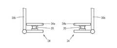
先ず、車椅子12には、図2〜図5に示すように、背もたれ22の背もたれ部22a内には圧電素子等による圧力分布センサ24が配置され、背もたれ部22aへの患者のもたれ具合を検出可能に設けられている。車椅子12の車輪26に近接したブレーキレバー28の近傍には、車椅子12の車体フレーム30の前方垂直フレーム30aに、フォトインタラプタ等の光学センサ32が取り付けられている。これにより、ブレーキレバー28の揺動動作による、車輪ロック状態とロック解除状態を検出可能としている。車椅子12の足置き部34にも、車体フレーム30から前方に延びた足置きフレーム30bに取り付けられたフォトインタラプタ等の光学センサ32が設けられている。これにより、足置き板34aが水平にされた使用状態と、跳ね上げられた不使用状態とを検出可能としている。光学センサ32は、レバー等の有無の二値状態を検知するものである。 First, in the
さらに車椅子12には、使用者である患者の使用状態における荷重の掛かり方を検知する圧電素子やその他の圧力センサから成る荷重センサ20が設けられている。足置き部34の足置き板34aには、図3に示すように、荷重センサ20が足置き板34aの内部に設けられ、患者が足置き板34aに足を載せた際の荷重を検出可能としている。 Furthermore, the
車椅子12の座面部38には、図4に示すように、車体フレーム30に固定された座面支持構造材40が設けられ、座面38の表面側の座面布38aを支持した座面布保持部材40aと座面支持構造材40の両端部の各間に荷重センサ20が一対ずつ設けられ、患者の着座を検知し、荷重の値を検出可能としている。 As shown in FIG. 4, the
車椅子12の肘掛け部42には、図5に示すように、肘掛け板42aの裏面の取付板42bと、車体フレーム30側の取付板42cとの間に、一対の荷重センサ20が前後方向端部に取り付けられている。肘掛け板42aの下面と車体フレーム30の上面との間には、ずれ防止用の保持部材44が挿入されている。 As shown in FIG. 5, the pair of
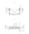
この実施形態の患者行動検知システム10に用いられるベッド14は、図6,図7に示すように、ベッド14の上面に載置された2枚の上面板52の裏面四隅に荷重センサ20が取り付けられ、患者がベッド14上に居る状態を検出可能としている。ベッド14の手摺り54には、水平部材54aの上面に歪みゲージセンサ50が貼り付けられ、垂直部材54bの周囲2方向にも、歪みゲージセンサ50が貼り付けられている。これにより、ベッド14及び手摺り54に掛かる力を検出可能としている。 As shown in FIGS. 6 and 7, the
さらにこの実施形態では、図8に示すように、トイレ16の壁に取り付けられた手摺り18の取付部材18aにも、歪みゲージセンサ50が3箇所に巻き付けられ、手摺り18に掛かる力とその方向を検出可能としている。取付部材18aに巻き付けられた歪みゲージセンサ50は、1本の取付部材18aに対して3本の歪みゲージセンサ50が取り付けられ、上下左右方向の力を検出可能としている。 Furthermore, in this embodiment, as shown in FIG. 8, the
この実施形態の患者行動検知システム10は、図1に示すように、各センサで検出した力の値や部材位置を無線通信を用いて、各種プログラムの処理装置であり記録装置であるパーソナルコンピュータ(以下、PCと称す。)60に送信可能に設けられている。PC60は、例えばノートパソコン程度の大きさのものを車椅子12に搭載して置くことができる。通信には、既存の短距離無線通信規格のZigbeeやBluetoothを用いることが出来る。また、USB端子を経由した有線によりデータを授受しても良い。例えば車椅子12に設けられたPC60には、通信アダプタが接続され、ベッド14とトイレ16には、送受信機62が据え付けられている。 As shown in FIG. 1, the patient behavior detection system 10 of this embodiment is a personal computer (processing device for various programs and a recording device) that uses force values and member positions detected by each sensor by wireless communication. (Hereinafter referred to as “PC”). The
各荷重センサ20の出力は、図示しないアンプを介して荷重に比例した値が出力され、図示しないA/D変換器を介して荷重の値を示すデジタルデータが送受信機62から出力され、PC60へ送られ、後述する所定の処理が処理プログラムにより行われて、荷重データが記憶装置64に記録される。 The output of each
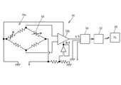
同様に、歪みゲージセンサ50の出力は、図9に示すセンサ回路56を介して、荷重の値が出力される。センサ回路56は、歪みゲージセンサ50をブリッジの一つに配置したブリッジ回路56aを備え、ブリッジ回路56aの一対の出力をアンプ56bに入力して、アンプ56bの出力が、A/D変換と荷重データの記録を行うデータロガー58に出力される。データロガー58に記録された荷重データは、送受信機62を介して、PC60内の記憶装置64に記録される。 Similarly, as the output of the
PC60内の処理は、図1、図10、図11に示すように、車椅子12、ベッド14、及びトイレ16に設けられた各センサにより取得されたセンサデータがPC60に送信され、所定のプログラムによりセンサデータが集約され、集約されたセンサデータに対して、その動作の動作識別処理が行われる。 As shown in FIGS. 1, 10, and 11, the processing in the
動作識別処理に先立ち、各センサからのデータを集約してその患者の行動パターンの分類の基準となる動作モデルを作成する。動作モデルの作成は、図11(a)に示すように、その患者の動作の特徴を抽出し、危険な動作か否かを判別するための動作の分類情報を蓄積し、動作モデルの情報を作成し、記憶装置64の動作モデル記憶部64aに記録する。ここで、センサデータの分類処理には、SVM(サポートベクターマシン・Support Vector Machine)を用いる。SVMは、教師あり学習を用いる識別手法の一つであり、非線形分類問題にも優れた性能を発揮することを特徴とする学習モデルである。そこで、この実施形態の動作分類には、SVMを用いて分類処理を行っている。 Prior to the motion identification process, the data from each sensor is aggregated to create a motion model that serves as a reference for classification of the behavior pattern of the patient. As shown in FIG. 11A, the motion model is created by extracting the features of the patient's motion, accumulating motion classification information for determining whether the motion is dangerous, and storing the motion model information. It is created and recorded in the behavior
先ず、図11(a)に示すように、センサデータを取得すると(s1)、取得した動作データの動作ラベリング(s2)と特徴量抽出処理(s3)を行う。この後、得られたラベルと特徴量データを基に、SVMを用いて、SVM分類による動作モデルを作成する(s4)。これにより、その患者の動作の各種パターンが分類されて各種の動作モデルが設定される。この動作モデルは、後に例えば患者の動作の識別に用いられる。 First, as shown in FIG. 11A, when sensor data is acquired (s1), operation labeling (s2) and feature amount extraction processing (s3) of the acquired operation data are performed. Thereafter, based on the obtained label and feature amount data, an operation model based on SVM classification is created using SVM (s4). Thereby, various patterns of the patient's motion are classified and various motion models are set. This motion model is later used, for example, to identify patient motion.
SVMモデルが作成された後は、図10に示すように、その患者の動作について動作識別処理が行われ、その後その患者の行動について危険か否かの行動判別処理が行われる。また、得られたセンサデータによる各動作の検出値は、記憶装置64内の動作ログ記憶部64bに動作時刻とともに記録される。患者動作に対する動作識別処理は、図11(b)に示すように、センサデータを取得し(s11)、センサデータの特徴量の抽出処理を行う(s12)。抽出した特徴量データをSVM分類処理する(s13)。このSVM分類処理には、先に作成したSVMモデルを動作モデル記憶部64aから呼び出して用いる。これにより、その患者のセンサデータによる動作識別がなされる。 After the SVM model is created, as shown in FIG. 10, an action identification process is performed for the movement of the patient, and then an action determination process for determining whether the patient's action is dangerous is performed. The detected value of each operation based on the obtained sensor data is recorded in the operation
動作識別処理が行われたセンサデータは、行動判別処理が施され、危険な動作であるか否かが判別される。判別には、記憶装置64内の行動ルール記憶部64cに記録された行動ルールが適用される。即ち、検出されたセンサデータが行動ルール記憶部64cの行動ルールに照らして、危険であると判断される場合は、アラーム生成部66からアラーム信号が送信され、その動作が行われている箇所の図示しないアラームが鳴り、患者やその周囲の人はその動作が危険であることを認識することができる。 The sensor data that has been subjected to the action identification process is subjected to an action determination process to determine whether it is a dangerous action. For the determination, an action rule recorded in the action
以上説明したように、この実施形態の患者行動識別方法と患者行動検知システム10は、患者の行動パターンを把握して、予めその患者の行動により得られる各センサからのセンサデータにより、その患者の危険な行動時に表れるセンサデータの値を認識し、これを基に、例えば在宅療養時に、上記患者行動を監視して、危険行動が起こる可能性のあるデータが得られた場合には、アラームを鳴らして、患者やその周囲の人に警告を発することが出来る。これにより、在宅療養時等の危険行動による事故を防止することが出来る。特に、行動時に得られるセンサデータのモデル作成や分類にSVMを用いることにより、正確な分類が可能となり、適切な判断が可能となる。 As described above, the patient behavior identification method and the patient behavior detection system 10 according to this embodiment grasps a patient's behavior pattern and uses the sensor data from each sensor obtained in advance based on the behavior of the patient to determine the patient's behavior. Recognize the value of sensor data that appears at the time of dangerous behavior, and based on this, monitor the above patient behavior during home medical treatment, for example, and if data that can cause dangerous behavior is obtained, an alarm is issued. It can be used to alert the patient and those around him. As a result, accidents due to dangerous behavior such as home medical treatment can be prevented. In particular, by using SVM for model creation and classification of sensor data obtained at the time of action, accurate classification is possible, and appropriate determination is possible.
なお、この発明の患者行動識別方法と患者行動検知システムは、上記実施形態に限定されるものではなく、センサの設置箇所は適宜選択可能なものであり、療養箇所の廊下等の手摺りや、洗面所に設置しても良く、センサの種類も適宜選択可能なものである。 The patient behavior identification method and the patient behavior detection system according to the present invention are not limited to the above-described embodiment, and the installation location of the sensor can be selected as appropriate. The sensor type may be selected as appropriate.
10 患者行動検知システム
12 車椅子
14 ベッド
16 トイレ
18 手摺り
20 荷重センサ
22 背もたれ
24 圧力分布センサ
30 車体フレーム
32 光学センサ
34 足置き部
38 座面部
50 歪みゲージセンサ
52 肘掛け部
60 PC
62 送受信機
64 記憶装置DESCRIPTION OF SYMBOLS 10 Patient
62 Transceiver 64 Storage device
Claims (6)
Translated fromJapaneseThe patient behavior detection system according to claim 5, wherein the plurality of devices includes a transceiver for wireless communication, and exchanges the sensor data with the processing device by wireless communication.
Priority Applications (1)
| Application Number | Priority Date | Filing Date | Title |
|---|---|---|---|
| JP2011179428AJP5867847B2 (en) | 2011-08-19 | 2011-08-19 | Patient behavior identification method and patient behavior detection system |
Applications Claiming Priority (1)
| Application Number | Priority Date | Filing Date | Title |
|---|---|---|---|
| JP2011179428AJP5867847B2 (en) | 2011-08-19 | 2011-08-19 | Patient behavior identification method and patient behavior detection system |
Publications (2)
| Publication Number | Publication Date |
|---|---|
| JP2013039300Atrue JP2013039300A (en) | 2013-02-28 |
| JP5867847B2 JP5867847B2 (en) | 2016-02-24 |
Family
ID=47888287
Family Applications (1)
| Application Number | Title | Priority Date | Filing Date |
|---|---|---|---|
| JP2011179428AExpired - Fee RelatedJP5867847B2 (en) | 2011-08-19 | 2011-08-19 | Patient behavior identification method and patient behavior detection system |
Country Status (1)
| Country | Link |
|---|---|
| JP (1) | JP5867847B2 (en) |
Cited By (5)
| Publication number | Priority date | Publication date | Assignee | Title |
|---|---|---|---|---|
| JP2018519032A (en)* | 2015-05-29 | 2018-07-19 | ヒル−ロム サービシズ,インコーポレイテッド | Patient support device |
| JP2020009378A (en)* | 2018-07-12 | 2020-01-16 | 医療法人社団皓有会 | Monitoring device |
| JP2020103553A (en)* | 2018-12-27 | 2020-07-09 | 甲斐 久順 | Contact sensor, seat for seating and wheelchair |
| JP2023033830A (en)* | 2021-08-30 | 2023-03-13 | 大和ハウス工業株式会社 | Daily living activity evaluation system and program |
| KR20240044836A (en)* | 2022-09-29 | 2024-04-05 | 이재완 | Bath wheelchair for people with mobility difficulties |
Families Citing this family (6)
| Publication number | Priority date | Publication date | Assignee | Title |
|---|---|---|---|---|
| US10555112B2 (en) | 2016-12-15 | 2020-02-04 | David H. Williams | Systems and methods for providing location-based security and/or privacy for restricting user access |
| US12342240B2 (en) | 2016-12-15 | 2025-06-24 | Conquer Your Addiction Llc | Systems and methods for monitoring for and lowering the risk of addiction-related or restriction violation-related behavior(s) |
| US10853897B2 (en) | 2016-12-15 | 2020-12-01 | David H. Williams | Systems and methods for developing, monitoring, and enforcing agreements, understandings, and/or contracts |
| US11636941B2 (en) | 2016-12-15 | 2023-04-25 | Conquer Your Addiction Llc | Dynamic and adaptive systems and methods for rewarding and/or disincentivizing behaviors |
| US10497242B2 (en) | 2016-12-15 | 2019-12-03 | David H. Williams | Systems and methods for monitoring for and preempting pre-identified restriction violation-related behavior(s) of persons under restriction |
| US11412353B2 (en) | 2016-12-15 | 2022-08-09 | Conquer Your Addiction Llc | Systems and methods for monitoring for and preempting the risk of a future occurrence of a quarantine violation |
Citations (9)
| Publication number | Priority date | Publication date | Assignee | Title |
|---|---|---|---|---|
| JP2001258859A (en)* | 2000-03-21 | 2001-09-25 | Hitachi Engineering & Services Co Ltd | Support system and support method for aged person care staff arrangement |
| JP2005081053A (en)* | 2003-09-11 | 2005-03-31 | Kid International:Kk | Seating cushion with sensor |
| US20050242946A1 (en)* | 2002-10-18 | 2005-11-03 | Hubbard James E Jr | Patient activity monitor |
| JP2007296326A (en)* | 2006-03-31 | 2007-11-15 | Cordis Corp | System and method for monitoring posture and movement |
| JP2009039466A (en)* | 2007-08-13 | 2009-02-26 | Advanced Telecommunication Research Institute International | Action identification device, action identification system, and action identification method |
| JP2009230335A (en)* | 2008-03-21 | 2009-10-08 | Aisin Seiki Co Ltd | Bed fall detection system and bed device |
| US20100045454A1 (en)* | 2008-03-03 | 2010-02-25 | Heather-Marie Callanan Knight | Wheelchair Alarm System and Method |
| US20100049095A1 (en)* | 2008-03-14 | 2010-02-25 | Stresscam Operations & Systems, Ltd. (c/o PHD Associates) | Assessment of medical conditions by determining mobility |
| JP2010063756A (en)* | 2008-09-12 | 2010-03-25 | Yokogawa Electric Corp | Body motion detecting device |
- 2011
- 2011-08-19JPJP2011179428Apatent/JP5867847B2/ennot_activeExpired - Fee Related
Patent Citations (9)
| Publication number | Priority date | Publication date | Assignee | Title |
|---|---|---|---|---|
| JP2001258859A (en)* | 2000-03-21 | 2001-09-25 | Hitachi Engineering & Services Co Ltd | Support system and support method for aged person care staff arrangement |
| US20050242946A1 (en)* | 2002-10-18 | 2005-11-03 | Hubbard James E Jr | Patient activity monitor |
| JP2005081053A (en)* | 2003-09-11 | 2005-03-31 | Kid International:Kk | Seating cushion with sensor |
| JP2007296326A (en)* | 2006-03-31 | 2007-11-15 | Cordis Corp | System and method for monitoring posture and movement |
| JP2009039466A (en)* | 2007-08-13 | 2009-02-26 | Advanced Telecommunication Research Institute International | Action identification device, action identification system, and action identification method |
| US20100045454A1 (en)* | 2008-03-03 | 2010-02-25 | Heather-Marie Callanan Knight | Wheelchair Alarm System and Method |
| US20100049095A1 (en)* | 2008-03-14 | 2010-02-25 | Stresscam Operations & Systems, Ltd. (c/o PHD Associates) | Assessment of medical conditions by determining mobility |
| JP2009230335A (en)* | 2008-03-21 | 2009-10-08 | Aisin Seiki Co Ltd | Bed fall detection system and bed device |
| JP2010063756A (en)* | 2008-09-12 | 2010-03-25 | Yokogawa Electric Corp | Body motion detecting device |
Non-Patent Citations (1)
| Title |
|---|
| JPN6015046844; 牛 童 外2名: '"RNN予測器を用いた人物行動パターンの自動分節化"' 電子情報通信学会技術研究報告 第108巻,第327号, 20081120, p.63-68, 社団法人電子情報通信学会* |
Cited By (9)
| Publication number | Priority date | Publication date | Assignee | Title |
|---|---|---|---|---|
| JP2018519032A (en)* | 2015-05-29 | 2018-07-19 | ヒル−ロム サービシズ,インコーポレイテッド | Patient support device |
| US10517784B2 (en) | 2015-05-29 | 2019-12-31 | Hill-Rom Services, Inc. | Patient support apparatus |
| US11135110B2 (en) | 2015-05-29 | 2021-10-05 | Hill-Rom Services, Inc. | Patient support apparatus |
| US12350211B2 (en) | 2015-05-29 | 2025-07-08 | Hill-Rom Services, Inc. | Patient support apparatus |
| JP2020009378A (en)* | 2018-07-12 | 2020-01-16 | 医療法人社団皓有会 | Monitoring device |
| JP2020103553A (en)* | 2018-12-27 | 2020-07-09 | 甲斐 久順 | Contact sensor, seat for seating and wheelchair |
| JP2023033830A (en)* | 2021-08-30 | 2023-03-13 | 大和ハウス工業株式会社 | Daily living activity evaluation system and program |
| KR20240044836A (en)* | 2022-09-29 | 2024-04-05 | 이재완 | Bath wheelchair for people with mobility difficulties |
| KR102682298B1 (en) | 2022-09-29 | 2024-07-05 | 이재완 | Bath wheelchair for people with mobility difficulties |
Also Published As
| Publication number | Publication date |
|---|---|
| JP5867847B2 (en) | 2016-02-24 |
Similar Documents
| Publication | Publication Date | Title |
|---|---|---|
| JP5867847B2 (en) | Patient behavior identification method and patient behavior detection system | |
| CN102150186B (en) | bed alarm system | |
| US10863927B2 (en) | Identifying fall risk using machine learning algorithms | |
| CN201200563Y (en) | Anti-fall care bed | |
| JP6012758B2 (en) | Method and computer program for monitoring the use of absorbent products | |
| CN101313877A (en) | Intelligent nursing bed with anti-fall function | |
| JP5877528B2 (en) | Automatic notification system | |
| JP2007283071A (en) | Scale with heartbeat and respiration measuring function | |
| US20210158965A1 (en) | Automated mobility assessment | |
| JP2011172674A (en) | Patient state information management system | |
| KR101131329B1 (en) | Toddler care system and method | |
| KR101767053B1 (en) | Mobile for automatic measuring and monitoring body temperature of babies and the method thereof | |
| KR20130039150A (en) | System and method for preventing driver sleeping | |
| JP6241820B2 (en) | Fall risk calculation system and reporting system | |
| JP2019101565A (en) | Management server and program | |
| JP5068602B2 (en) | Bed equipment | |
| JP6874048B2 (en) | State judgment device | |
| Karunanithi et al. | An innovative technology to support independent living: the smarter safer homes platform | |
| JP2020190889A (en) | Watching system for people requiring care | |
| JP2008257280A (en) | User identification device | |
| Yeh et al. | Internet-of-Things Management of Medical Chairs and Wheelchairs. | |
| Madokoro et al. | Prediction of bed-leaving behaviors using piezoelectric non-restraining sensors | |
| JP2020091628A (en) | Caregiver watching system | |
| KR101843787B1 (en) | Method and system for alarming safety by wireless network based on bio sensing | |
| KR20230103282A (en) | Transfer assistant robot able to collect operational data |
Legal Events
| Date | Code | Title | Description |
|---|---|---|---|
| A621 | Written request for application examination | Free format text:JAPANESE INTERMEDIATE CODE: A621 Effective date:20140725 | |
| A977 | Report on retrieval | Free format text:JAPANESE INTERMEDIATE CODE: A971007 Effective date:20150414 | |
| A131 | Notification of reasons for refusal | Free format text:JAPANESE INTERMEDIATE CODE: A131 Effective date:20150421 | |
| A521 | Request for written amendment filed | Free format text:JAPANESE INTERMEDIATE CODE: A523 Effective date:20150619 | |
| TRDD | Decision of grant or rejection written | ||
| A01 | Written decision to grant a patent or to grant a registration (utility model) | Free format text:JAPANESE INTERMEDIATE CODE: A01 Effective date:20151124 | |
| A61 | First payment of annual fees (during grant procedure) | Free format text:JAPANESE INTERMEDIATE CODE: A61 Effective date:20151225 | |
| R150 | Certificate of patent or registration of utility model | Ref document number:5867847 Country of ref document:JP Free format text:JAPANESE INTERMEDIATE CODE: R150 | |
| R250 | Receipt of annual fees | Free format text:JAPANESE INTERMEDIATE CODE: R250 | |
| R250 | Receipt of annual fees | Free format text:JAPANESE INTERMEDIATE CODE: R250 | |
| R250 | Receipt of annual fees | Free format text:JAPANESE INTERMEDIATE CODE: R250 | |
| LAPS | Cancellation because of no payment of annual fees |