JP2013037926A - Light irradiation device - Google Patents
Light irradiation deviceDownload PDFInfo
- Publication number
- JP2013037926A JP2013037926AJP2011173649AJP2011173649AJP2013037926AJP 2013037926 AJP2013037926 AJP 2013037926AJP 2011173649 AJP2011173649 AJP 2011173649AJP 2011173649 AJP2011173649 AJP 2011173649AJP 2013037926 AJP2013037926 AJP 2013037926A
- Authority
- JP
- Japan
- Prior art keywords
- light
- incident
- optical axis
- led
- light guide
- Prior art date
- Legal status (The legal status is an assumption and is not a legal conclusion. Google has not performed a legal analysis and makes no representation as to the accuracy of the status listed.)
- Withdrawn
Links
Images


Landscapes
- Non-Portable Lighting Devices Or Systems Thereof (AREA)
- Planar Illumination Modules (AREA)
Abstract
Translated fromJapaneseDescription
Translated fromJapanese本発明は、光照射装置に関する。 The present invention relates to a light irradiation apparatus.
従来、光硬化樹脂に紫外線等の光を照射して当該光硬化樹脂を重合・硬化させる光照射装置が知られている(例えば、特許文献1参照)。 2. Description of the Related Art Conventionally, a light irradiation apparatus that irradiates a photocurable resin with light such as ultraviolet rays to polymerize and cure the photocurable resin is known (see, for example, Patent Document 1).
上記特許文献1に記載の光照射装置80は、図15に示すように、左右方向に配列された複数のLED81,…と、各LED81の前方に配置された複数のメニスカスレンズ82,…と、全てのメニスカスレンズ82,…の前方に亘って配設された長尺なシリンダーレンズ83とを備えている。 As shown in FIG. 15, the
この光照射装置80では、LED81,…から出射された光を、メニスカスレンズ82,…により照度分布を均一に保持しつつ、シリンダーレンズ83で幅方向(紙面垂直方向)に集光させることにより、当該光を左右方向に長尺なライン状に照射している。 In this
しかしながら、一般にLEDから出射される光は出射角度(光軸からの出射方向の角度)が大きくなるに連れて弱くなるところ、上記特許文献1に記載の光照射装置80では、LED81から出射された光を単純に前方へ照射しているため、被照射面のうち光軸上付近の中央領域に強い光が照射され、その周縁の端部領域には相対的に弱い光が照射されてしまう。その結果、被照射面において光硬化樹脂に光を照射したときに、この光硬化樹脂の端部を十分に硬化させることができない。 However, in general, the light emitted from the LED is weakened as the emission angle (the angle in the emission direction from the optical axis) increases. In the
本発明は、上記事情を鑑みてなされたもので、被照射面の端部領域へ強い光を照射することができる光照射装置の提供を課題とする。 This invention is made | formed in view of the said situation, and makes it a subject to provide the light irradiation apparatus which can irradiate strong light to the edge part area | region of a to-be-irradiated surface.
上記課題を解決するために、請求項1に記載の発明は、
光軸を前方へ向けたLEDと、前記LEDの前方に配置された導光体と、を備え、前記LEDから出射された光を前記導光体の前方の被照射面へ照射する光照射装置において、
前記導光体は、
前記LEDと対向する位置に設けられ、前記LEDから出射された光を前記光軸に沿った光軸方向への平行光としつつ当該導光体内へ入射させる入射部と、
前記入射部の前記光軸方向に位置する部分のうちの中央部に設けられ、前記入射部から入射した光を当該導光体内から前方へ出射させて前記被照射面へ照射する中央出射面と、
前記被照射面のうちの端部領域と対向する位置に設けられ、当該導光体内から前方へ光を出射させて前記端部領域へ照射する端部出射面と、
前記入射部から入射した光のうち、前記中央出射面から出射される光を除くものを、前記端部出射面へ向けて内部反射させる反射面と、
を有することを特徴とする。In order to solve the above-mentioned problem, the invention described in
A light irradiation device comprising: an LED having an optical axis directed forward; and a light guide disposed in front of the LED, and irradiating light emitted from the LED to an irradiated surface in front of the light guide In
The light guide is
An incident part that is provided at a position facing the LED, and enters the light guide body while making the light emitted from the LED parallel light in the optical axis direction along the optical axis;
A central exit surface that is provided at a central portion of the portion of the incident portion that is positioned in the optical axis direction and that emits light incident from the incident portion forward from the light guide body and irradiates the irradiated surface; ,
An end emission surface that is provided at a position facing the end region of the irradiated surface, emits light forward from the light guide, and irradiates the end region;
Of the light incident from the incident portion, a reflection surface that internally reflects the light emitted from the central emission surface toward the end emission surface;
It is characterized by having.
請求項2に記載の発明は、請求項1に記載の光照射装置において、
前記反射面は、
前記入射部の前記光軸方向に位置する部分のうち前記中央出射面の周囲に設けられ、前記入射部から入射した光のうち、前記中央出射面から出射される光を除くものを、前記光軸方向と直交する複数の第一光軸直交方向へ分岐するように内部反射させる第一分岐反射面と、
前記第一分岐反射面の前記第一光軸直交方向に設けられ、当該第一分岐反射面で内部反射された光を当該第一光軸直交方向及び前記光軸方向の何れとも直交する第二光軸直交方向の両側へ分岐するように内部反射させる第二分岐反射面と、
前記第二分岐反射面の前記第二光軸直交方向の両側にそれぞれ設けられ、当該第二分岐反射面で内部反射された光を前記光軸方向へ個別に内部反射させる内部反射面と、
からなり、
前記端部出射面は、前記内部反射面の前記光軸方向に設けられていることを特徴とする。The invention according to
The reflective surface is
Among the portions of the incident portion that are positioned in the optical axis direction, provided around the central emission surface, the light that has entered the incident portion excluding the light emitted from the central emission surface is the light. A first branched reflecting surface that internally reflects so as to branch in a plurality of first optical axis orthogonal directions orthogonal to the axial direction;
A second light that is provided in the first optical axis orthogonal direction of the first branched reflective surface and that is internally reflected by the first branched reflective surface is orthogonal to both the first optical axis orthogonal direction and the optical axis direction. A second branched reflecting surface for internal reflection so as to branch to both sides in the direction perpendicular to the optical axis;
An internal reflection surface that is provided on each side of the second branch reflection surface in the direction orthogonal to the second optical axis, and individually internally reflects light internally reflected by the second branch reflection surface in the optical axis direction;
Consists of
The end emission surface is provided in the optical axis direction of the internal reflection surface.
請求項3に記載の発明は、請求項1又は2に記載の光照射装置において、
前記入射部は、
前記LEDと対向する位置に設けられ、前記LEDから出射された光を前記光軸方向へ屈折させつつ前記導光体内へ入射させる第一入射面と、
前記第一入射面の周縁部から前記LED側へ立設され、前記LEDから出射されて前記第一入射面よりも側方へ向かう光を前記導光体内へ入射させる第二入射面と、
前記第二入射面の先端から前記光軸方向へ向かって外側へ広がるように傾斜した形状に形成され、前記第二入射面から前記導光体内へ入射した光を前記光軸方向へ内部反射させる入射部反射面と、
を有することを特徴とする。The invention according to
The incident portion is
A first incident surface that is provided at a position facing the LED and that enters the light guide body while refracting light emitted from the LED in the optical axis direction;
A second incident surface that is erected from the peripheral edge of the first incident surface to the LED side, and that enters the light guide body with light emitted from the LED and directed to the side of the first incident surface;
It is formed in a shape that is inclined so as to spread outward from the tip of the second incident surface toward the optical axis direction, and internally reflects light incident on the light guide from the second incident surface in the optical axis direction. An incident part reflection surface;
It is characterized by having.
本発明によれば、LEDから出射されて入射部から導光体内に入射した光のうちの中央部のものが、中央出射面から前方へ出射されて被照射面へ照射される一方、入射部から導光体内に入射した光のうち中央出射面から出射される光を除くものが、反射面で内部反射された後に端部出射面から前方へ出射されて被照射面のうちの端部領域へ照射されるので、中央出射面から出射される一部の光を被照射面へ照射しつつ、当該一部の光を除く光を端部出射面から被照射面の端部領域へ重点的に照射することができる。したがって、被照射面の端部領域には弱い光しか照射することができなかった従来に比べ、被照射面の端部領域へ強い光を照射することができる。 According to the present invention, the light emitted from the LED and incident from the incident portion into the light guide body is emitted from the central emission surface to the front and irradiated to the irradiated surface, while the incident portion. Of the light incident on the light guide from the central exit surface, except for the light emitted from the central exit surface, is internally reflected by the reflective surface, and then exits forward from the end exit surface to the end region of the irradiated surface. Therefore, while irradiating the irradiated surface with a part of the light emitted from the central exit surface, the light excluding the part of the light is focused from the end exit surface to the end region of the irradiated surface. Can be irradiated. Therefore, it is possible to irradiate the end region of the irradiated surface with strong light, compared to the conventional case where only the weak region can irradiate the end region of the irradiated surface.
以下、本発明の実施形態について、図面を参照して説明する。
なお、以下の説明では、「前」「後」との記載は、各実施形態における光照射装置から見た方向を指すものとする。また、各実施形態における光照射装置の前後方向に沿って後方から前方へ向かう方向を「Z方向」とし、Z方向と直交し、且つ互いに直交する2方向を「X方向」及び「Y方向」とする。Hereinafter, embodiments of the present invention will be described with reference to the drawings.
In the following description, the descriptions “front” and “rear” refer to directions viewed from the light irradiation apparatus in each embodiment. Further, the direction from the rear to the front along the front-rear direction of the light irradiation device in each embodiment is referred to as “Z direction”, and two directions orthogonal to the Z direction and orthogonal to each other are “X direction” and “Y direction”. And
[第一の実施形態]
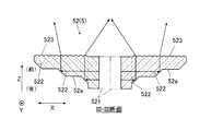
図1は、本発明の第一の実施形態における光照射装置1の斜視図であり、図2は、光照射装置1の正面(前面)図であり、図3及び図4は、図2のII−II線及びIII−III線での断面図である。[First embodiment]
FIG. 1 is a perspective view of the
図1及び図2に示すように、光照射装置1は、例えば紫外線硬化樹脂(図示せず)等に紫外線を照射する紫外線照射装置であり、LED(発光ダイオード)4と、LED4の前方に配置された導光体5とを備えている。
このうち、LED4は、紫外領域のピーク波長(例えば、365nm,385nm等)を有する紫外線を出射させるものであり、光軸AxをZ方向に沿って前方へ向けた状態に配置され、当該光軸Axを中心に前方へ略放射状に紫外線を出射させる。As shown in FIGS. 1 and 2, the
Among these, the
導光体5は、LED4から出射された紫外線を前方へ照射するものである。この導光体5は、Y方向に沿って延在する第一延在部51と、第一延在部51のY方向両端からX方向に沿って延在する2つの第二延在部52,52とから構成されている。 The
図3に示すように、第一延在部51は、そのY方向中央の後方にLED4が位置するように配設されており、このLED4と対向する部分には、当該LED4から出射された紫外線をZ方向への平行光としつつ導光体5内に入射させる入射部510が設けられている。入射部510は、光軸Axを回転対称軸として後方へ突出する裁頭円錐状に形成されており、その後端には、後方へ開口する凹部510aが形成されている。
凹部510aの底部には、後方へ膨出する凸面状(非球面)の第一入射面511が、光軸Axを回転対称軸としてLED4と対向する位置に設けられている。この第一入射面511は、その焦点にLED4が位置するとともに、LED4から当該第一入射面511の外周縁への紫外線の出射角度が所定角度(例えば20°)となるように形成されており、LED4から出射された紫外線のうち出射角度が所定角度未満のものを、Z方向に沿うように屈折させてZ方向への平行光としつつ導光体5内へ入射させる。
凹部510aの内周面は、第二入射面512となっている。この第二入射面512は、LED4の前方を覆うように第一入射面511の周縁部からLED4側(後方)へ立設された裁頭円錐面であり、LED4から出射された紫外線のうち第一入射面511よりも側方へ向かうもの,つまり出射角度が所定角度以上のものを導光体5内へ入射させる。
入射部510の外周面は、入射部反射面513となっている。この入射部反射面513は、第二入射面512の先端(後端)からZ方向へ向かって外側(光軸Axから遠い側)へ広がるように傾斜した裁頭円錐面であり、第二入射面512から導光体5内へ入射した紫外線を、Z方向に沿うように内部反射させてZ方向への平行光とする。As shown in FIG. 3, the first extending
A convex (aspherical)
The inner peripheral surface of the
The outer peripheral surface of the
第一延在部51の前面のうち、入射部510のZ方向に位置する部分には、前方へ突設された突設部514と、2つの第一分岐反射面515,515とが設けられている。
このうち、突設部514は、入射部510のZ方向に位置する部分のうちの中央部に設けられており、光軸Axを回転対称軸とする円柱状に形成されている。また、特に限定はされないが、突設部514の外径は、第一入射面511の正面視形状の外径と略一致している。この突設部514の前端面は、前方へ膨出する凸面状の中央出射面514aとなっている。この中央出射面514aは、入射部510から導光体5内に入射した紫外線のうち光軸Ax周辺の中央部のものを、導光体5内から前方へ拡散させつつ出射させ、紫外線の照射対象(例えば紫外線硬化樹脂等)が配置される導光体5の前方の被照射面S(図5参照)全体へ照射する。
一方、2つの第一分岐反射面515,515は、入射部510のZ方向に位置する部分のうち突設部514の周囲全面に亘って、前方へ開口するように凹設されている。この第一分岐反射面515,515は、光軸Axを通りX方向に沿った線を基端線として、光軸Axを含むXZ平面をY方向の両側へ45度の角度で個別に傾斜させた1対の平面となっており、入射部510から導光体5内に入射した紫外線のうち、中央出射面514aから出射される紫外線を除くものを、光軸Axを境にY方向の両側へ分岐するように内部反射させる。Of the front surface of the first extending
Among these, the protruding
On the other hand, the two first branched reflecting
図2に示すように、2つの第二延在部52,52は、それぞれのX方向の中央部で第一延在部51のY方向の両端部と一体的に連なっており、光軸Axを含むYZ平面について面対称にそれぞれ形成されている。
第二延在部52,52のX方向の中央部には、2対の第二分岐反射面521,…がY方向の両側へ開口するように凹設されている。各対の第二分岐反射面521,521は、光軸AxをY方向へスライドさせた線を基端線として、光軸Axを含むYZ平面をX方向の両側へ45度の角度で個別に傾斜させた1対の平面となっている。この2対の第二分岐反射面521,…は、第一分岐反射面515,515のY方向の両側に位置しており、当該第一分岐反射面515,515でY方向の両側へ内部反射された紫外線を、それぞれX方向の両側へ分岐するように内部反射させる。As shown in FIG. 2, the two second extending
Two pairs of second
図4に示すように、各第二延在部52の後面のうち、第二分岐反射面521,521のX方向の両側には、複数の内部反射面522,…がそれぞれ設けられている。内部反射面522,…は、第二分岐反射面521,521のX方向の両側それぞれにおいて、当該一対の第二分岐反射面521,521のうち何れか近い方と平行になるように、つまりYZ平面に対して45度の角度でX方向へ傾斜するようにそれぞれ形成されている。そして、当該内部反射面522,…は、Z方向と直交する段面52aとX方向へ交互に連なることで、X方向に沿って第二分岐反射面521,521から離れるに連れて段階的に前方に位置するような階段状の面を構成している。この内部反射面522,…は、第二分岐反射面521,521でX方向の両側へ内部反射された紫外線をZ方向へ個別に内部反射させる。 As shown in FIG. 4, a plurality of internal reflection surfaces 522,... Are provided on both sides in the X direction of the second branch reflection surfaces 521 521 among the rear surfaces of the respective second extending
各第二延在部52の前面のうち、第二分岐反射面521,521のX方向の両側には、2つの端部出射面523,523が設けられている。各端部出射面523は、Z方向と直交する基準面上に複数のレンズカットが形成された面となっている。複数のレンズカットは、Y方向に沿った母線を有してZ方向へ膨らむシリンドリカル面状にそれぞれ形成され、基準面の全面に亘ってX方向に並設されている(図1参照)。端部出射面523は、内部反射面522,…のZ方向に位置しており、内部反射面522,…でZ方向へ内部反射された紫外線を、複数のレンズカットによりX方向へ拡散させつつ導光体5内から前方へ出射させて、被照射面Sのうちの端部領域Saへ照射する(図5参照)。
ここで、端部領域Saとは、被照射面Sのうち、2つの端部出射面523,523に対向する領域部分と、当該2つの端部出射面523,523の間の導光体5部分(第二分岐反射面521,521が位置する部分)に対向する領域部分とが連なった領域であり、被照射面SのY方向の端部に位置する領域である。この端部領域Saのうち、2つの端部出射面523,523の間の導光体5部分と対向する領域部分には、端部出射面523,523から出射される紫外線がレンズカットによってX方向に拡散されることにより、当該紫外線が照射される。Two
Here, the end region Sa is the
続いて、光照射装置1における紫外線の照射態様について説明する。 Then, the ultraviolet irradiation mode in the
図3に示すように、LED4から出射された紫外線のうち、出射角度が所定角度未満のものは、第一入射面511を通じてZ方向に沿った平行光とされつつ導光体5内へ入射する。また、LED4から出射された紫外線のうち、出射角度が所定角度以上のものは、第二入射面512を通じて屈折されつつ導光体5内へ入射した後に、入射部反射面513によってZ方向へ内部反射される。こうして、LED4から出射された全ての紫外線は、入射部510によってZ方向への平行光とされる。 As shown in FIG. 3, among the ultraviolet rays emitted from the
入射部510で平行光とされた紫外線のうち、光軸Ax周辺の中央部のものは、突設部514の中央出射面514aから前方へ拡散されつつ出射され、導光体5の前方の被照射面S全体へ照射される(図5参照)。
一方、入射部510で平行光とされた紫外線のうち、中央出射面514aから出射しない周辺部のものは、第一分岐反射面515,515により光軸Axを境にY方向の両側へ分岐するように内部反射される。Of the ultraviolet rays converted into parallel light by the
On the other hand, of the ultraviolet rays converted into parallel light by the
第一分岐反射面515,515でY方向の両側へ分岐された紫外線は、図2及び図4に示すように、それぞれ第二分岐反射面521,521によりX方向の両側へ分岐するように内部反射される。第二分岐反射面521,521でX方向の両側へ分岐された紫外線は、X方向へ断続的に分布する内部反射面522,…によってX方向に分散されつつZ方向へ個別に内部反射される。 The ultraviolet rays branched to both sides in the Y direction by the first
内部反射面522,…でZ方向へ内部反射された紫外線は、端部出射面523を通じてX方向へ拡散されつつ前方へ出射され、図5に示すように、被照射面Sのうち、Y方向両端の端部領域Sa,Saへ照射される。 The ultraviolet rays internally reflected in the Z direction by the internal reflecting
以上のように、光照射装置1によれば、LED4から出射されて入射部510から導光体5内に入射した紫外線のうちの中央部のものが、中央出射面514aから前方へ出射されて被照射面Sへ照射される一方、入射部510から導光体5内に入射した紫外線のうち中央出射面514aから出射される紫外線を除くものが、第一分岐反射面515,第二分岐反射面521及び内部反射面522で内部反射された後に端部出射面523から前方へ出射されて被照射面Sのうちの端部領域Saへ照射される。これにより、中央出射面514aから出射される一部の紫外線を被照射面Sへ照射しつつ、当該一部の紫外線を除く残りの紫外線を端部出射面523から被照射面Sの端部領域Saへ重点的に照射することができる。したがって、被照射面の端部領域には弱い光しか照射することができなかった従来に比べ、被照射面Sの端部領域Saへ強い光を照射することができる。 As described above, according to the
また、入射部510が、LED4と対向する位置に設けられた第一入射面511と、第一入射面511の周縁部からLED4側へ立設された第二入射面512とを有するので、LED4から小さな出射角度で出射された紫外線を第一入射面511から導光体5内へ入射させるとともに、LED4から大きな出射角度で出射された紫外線を第二入射面512から導光体5内へ入射させることができる。そして、上述の通り、これらの紫外線を被照射面Sへ照射することができる。したがって、LED4から出射された全ての紫外線を有効に利用することができる。 Moreover, since the
[第二の実施形態]
続いて、本発明の第二の実施形態について説明する。なお、上記第一の実施形態と同様の構成要素には同一の符号を付し、その説明を省略する。[Second Embodiment]
Next, a second embodiment of the present invention will be described. In addition, the same code | symbol is attached | subjected to the component similar to said 1st embodiment, and the description is abbreviate | omitted.
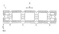
図6は、本発明の第二の実施形態における光照射装置2の斜視図であり、図7は、光照射装置2の正面(前面)図であり、図8〜図10は、図7のIV−IV線〜VI−VI線での断面図である。 6 is a perspective view of the
図6及び図7に示すように、光照射装置2は、上記第一の実施形態における光照射装置1と同様の紫外線照射装置であり、LED4と、LED4の前方に配置された導光体6とを備えている。 As shown in FIGS. 6 and 7, the
導光体6は、LED4から出射された紫外線を前方へ照射するものである。この導光体6は、Y方向に沿って延在する第一延在部61と、第一延在部61のY方向両端からX方向に沿って延在する2つの第二延在部62,62と、第一延在部61のY方向中央からX方向の一方へ延在する第三延在部63と、第三延在部63のX方向先端からY方向に沿って延在する第四延在部64とから構成されている。 The
このうち、第一延在部61及び第三延在部63は、図7〜図9に示すように、光軸Axが連結中心に位置するようにLED4の前方で一体的に連結されており、この連結部に入射部510及び突設部514が設けられている。また、この連結部の前面には、3つの第一分岐反射面615,…が、入射部510のZ方向に位置する部分のうち突設部514の周囲全面に亘って、前方へ開口するように凹設されている。3つの第一分岐反射面615,…は、光軸Axを中心として内角が120度の扇状の正面視形状にそれぞれ形成されている。この3つの第一分岐反射面615,…のうち、2つの第一分岐反射面615a,615aは、第一延在部61の前面に形成され、光軸Axを通りX方向に沿った線を基端線として、光軸Axを含むXZ平面をY方向の両側へ45度の角度で個別に傾斜させた1対の平面となっている。一方、残る1つの第一分岐反射面615bは、第三延在部63の前面に形成され、光軸Axを含むYZ平面をX方向の一方(連結部から離間する方向)へ45度の角度で傾斜させた平面となっている。この3つの第一分岐反射面615,…は、入射部510から導光体6内に入射した紫外線のうち、突設部514先端の中央出射面514aから出射される紫外線を除くものを、Y方向の両側とX方向の一方側との3方向へ分岐するように内部反射させる。 Among these, as shown in FIGS. 7-9, the
第二延在部62,62は、上記第一の実施形態における第二延在部52,52と略同様に構成されている。但し、本第二の実施形態における各対の第二分岐反射面521,521は、第一分岐反射面615a,615aのY方向に位置しており、当該第一分岐反射面615a,615aのX方向長さの中心位置を通るYZ平面をX方向の両側へ45度の角度で個別に傾斜させた1対の平面となっている。 The second extending
図7及び図10に示すように、第四延在部64は、Y方向の中央部で第三延在部63のX方向の先端部と一体的に連なるとともに、Y方向の両端部で第二延在部62,62の各一端部と一体的に連なっている。この第四延在部64は、上記第一の実施形態における第二延在部52をY方向に沿って延在させた形状に形成されている。したがって、第四延在部64は、上記第一の実施形態における一対の第二分岐反射面521,521と、複数の内部反射面522,…と、2つの端部出射面523,523とをZ方向回りに90度回転させた一対の第二分岐反射面641,641と、複数の内部反射面642,…と、2つの端部出射面643,643とを有している。 As shown in FIGS. 7 and 10, the fourth extending
このうち、端部出射面643,643は、導光体6内から前方へ紫外線を出射させて被照射面Sのうちの端部領域Sbへ照射する(図11参照)。ここで、端部領域Sbとは、被照射面Sのうち、2つの端部出射面643,643に対向する領域部分と、当該2つの端部出射面643,643の間の導光体6部分(第二分岐反射面641,641が位置する部分)に対向する領域部分とが連なった領域であり、被照射面SのX方向の端部に位置する領域である。この端部領域Sbのうち、2つの端部出射面643,643の間の導光体6部分と対向する領域部分には、端部出射面643,643から出射される紫外線がレンズカットによってY方向に拡散されることにより、当該紫外線が照射される。 Among these, the end emission surfaces 643 and 643 emit ultraviolet rays forward from the
続いて、光照射装置2における紫外線の照射態様について説明する。 Then, the ultraviolet irradiation mode in the
図8及び図9に示すように、LED4から出射された全ての紫外線は、上記第一の実施形態と同様にして、入射部510によってZ方向への平行光とされつつ導光体6内へ入射する。 As shown in FIGS. 8 and 9, all the ultraviolet rays emitted from the
入射部510で平行光とされた紫外線のうち、光軸Ax周辺の中央部のものは、突設部514の中央出射面514aから前方へ拡散されつつ出射され、導光体6の前方の被照射面S全体へ照射される(図11参照)。
一方、入射部510で平行光とされた紫外線のうち、中央出射面514aから出射しない周辺部のものは、3つの第一分岐反射面615,…により3方向へ分岐するように内部反射される。具体的には、当該紫外線は、2つの第一分岐反射面615a,615aによりY方向の両側へ内部反射され、第一分岐反射面615bによりX方向の一方側へ内部反射される。Of the ultraviolet rays that have been converted into parallel light by the
On the other hand, of the ultraviolet rays converted into parallel light by the
このうち、第一分岐反射面615a,615aでY方向の両側へ分岐された紫外線は、図4及び図7に示すように、それぞれ第二分岐反射面521,521によりX方向の両側へ分岐するように内部反射された後に、内部反射面522,…によってX方向に分散されつつZ方向へ個別に内部反射される。そして、この紫外線は、端部出射面523を通じてX方向へ拡散されつつ前方へ出射され、図11に示すように、被照射面Sのうち、Y方向両端の端部領域Sa,Saへ照射される。 Among these, the ultraviolet rays branched to both sides in the Y direction by the first
一方、第一分岐反射面615bでX方向の一方側へ内部反射された紫外線は、図7及び図10に示すように、第二分岐反射面641,641によりY方向の両側へ分岐するように内部反射された後に、内部反射面642,…によってY方向に分散されつつZ方向へ個別に内部反射される。そして、この紫外線は、端部出射面643を通じてY方向へ拡散されつつ前方へ出射され、図11に示すように、被照射面Sのうち、X方向の一端の端部領域Sbへ照射される。 On the other hand, the ultraviolet rays internally reflected to one side in the X direction by the first
以上のように、光照射装置2によれば、上記第一の実施形態における光照射装置1と同様の効果を奏することができる。 As mentioned above, according to the
[第三の実施形態]
続いて、本発明の第三の実施形態について説明する。なお、上記第一及び第二の実施形態と同様の構成要素には同一の符号を付し、その説明を省略する。[Third embodiment]
Subsequently, a third embodiment of the present invention will be described. In addition, the same code | symbol is attached | subjected to the component similar to the said 1st and 2nd embodiment, and the description is abbreviate | omitted.
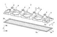
図12は、本発明の第三の実施形態における光照射装置3の斜視図であり、図13は、光照射装置3の正面(前面)図であり、図14は、光照射装置3からの紫外線が照射される被照射面Sを説明するための図である。 12 is a perspective view of the
これらの図に示すように、光照射装置3は、上記第一の実施形態における光照射装置1と、上記第二の実施形態における光照射装置2とをX方向に沿って並設した構成となっている。具体的には、光照射装置3は、複数のLED4,…と、LED4,…の前方に配置された導光体7とを備えている。 As shown in these drawings, the
導光体7は、上記第一の実施形態における導光体5と、上記第二の実施形態における導光体6とを連結させた形状に形成されており、より詳細には、2つの導光体5,5をX方向に沿って連結させ、当該2つの導光体5,5のX方向の両側に2つの導光体6,6を連結させた形状に形成されている。但し、導光体6,6は、それぞれの第四延在部64が導光体7のX方向両端に位置するように、一方がZ方向回りに半回転されている。 The
以上の構成を具備する光照射装置3では、LED4,…から出射された紫外線が、導光体7を通じて、導光体7の前方の被照射面Sのうち、端部領域Saと端部領域Sbとが連なった全周縁部へ照射される。 In the
以上のように、光照射装置3によれば、上記第一の実施形態における光照射装置1と同様の効果を奏することができる。 As described above, according to the
なお、本発明を適用可能な実施形態は、上述した第一〜第三の実施形態に限定されることなく、本発明の趣旨を逸脱しない範囲で適宜変更可能である。 The embodiments to which the present invention can be applied are not limited to the first to third embodiments described above, and can be appropriately changed without departing from the spirit of the present invention.
例えば、上記第一〜第三の実施形態では、LED4が紫外線を出射させることとしたが、当該LED4が出射する光は、光硬化樹脂を硬化させる特定波長の光であればよく、紫外線以外の光であってもよい。 For example, in the first to third embodiments, the
また、中央出射面514aが紫外線を照射する範囲は、被照射面Sの全体でなくともよく、被照射面Sの一部(例えば、被照射面Sのうち端部領域Sa及び端部領域Sbを除く部分)であってもよい。 In addition, the range in which the
また、中央出射面514aは、被照射面Sの所定範囲に亘って紫外線を照射できれば、つまり紫外線を拡散させつつ前方へ出射できればよく、前方へ膨出する凸面状の面でなくともよい。例えば、当該中央出射面514aは、凹面状の面であってもよいし、複数の傾斜平面を光軸Ax回りに連ねた面であってもよい。 Further, the
1,2,3 光照射装置
4 LED
Ax 光軸
5,6,7 導光体
51,61 第一延在部
510 入射部
511 第一入射面
512 第二入射面
513 入射部反射面
514 突設部
514a 中央出射面
515,615 第一分岐反射面
52,62 第二延在部
521 第二分岐反射面
522 内部反射面
523 端部出射面
63 第三延在部
64 第四延在部
641 第二分岐反射面
642 内部反射面
643 端部出射面
S 被照射面
Sa 端部領域
Sb 端部領域
X 方向(第一光軸直交方向,第二光軸直交方向)
Y 方向(第一光軸直交方向,第二光軸直交方向)
Z 方向(光軸方向)1, 2, 3
Ax
Y direction (first optical axis orthogonal direction, second optical axis orthogonal direction)
Z direction (optical axis direction)
Claims (3)
Translated fromJapanese前記導光体は、
前記LEDと対向する位置に設けられ、前記LEDから出射された光を前記光軸に沿った光軸方向への平行光としつつ当該導光体内へ入射させる入射部と、
前記入射部の前記光軸方向に位置する部分のうちの中央部に設けられ、前記入射部から入射した光を当該導光体内から前方へ出射させて前記被照射面へ照射する中央出射面と、
前記被照射面のうちの端部領域と対向する位置に設けられ、当該導光体内から前方へ光を出射させて前記端部領域へ照射する端部出射面と、
前記入射部から入射した光のうち、前記中央出射面から出射される光を除くものを、前記端部出射面へ向けて内部反射させる反射面と、
を有することを特徴とする光照射装置。A light irradiation device comprising: an LED having an optical axis directed forward; and a light guide disposed in front of the LED, and irradiating light emitted from the LED to an irradiated surface in front of the light guide In
The light guide is
An incident part that is provided at a position facing the LED, and enters the light guide body while making the light emitted from the LED parallel light in the optical axis direction along the optical axis;
A central exit surface that is provided at a central portion of the portion of the incident portion that is positioned in the optical axis direction and that emits light incident from the incident portion forward from the light guide body and irradiates the irradiated surface; ,
An end emission surface that is provided at a position facing the end region of the irradiated surface, emits light forward from the light guide, and irradiates the end region;
Of the light incident from the incident portion, a reflection surface that internally reflects the light emitted from the central emission surface toward the end emission surface;
The light irradiation apparatus characterized by having.
前記入射部の前記光軸方向に位置する部分のうち前記中央出射面の周囲に設けられ、前記入射部から入射した光のうち、前記中央出射面から出射される光を除くものを、前記光軸方向と直交する複数の第一光軸直交方向へ分岐するように内部反射させる第一分岐反射面と、
前記第一分岐反射面の前記第一光軸直交方向に設けられ、当該第一分岐反射面で内部反射された光を当該第一光軸直交方向及び前記光軸方向の何れとも直交する第二光軸直交方向の両側へ分岐するように内部反射させる第二分岐反射面と、
前記第二分岐反射面の前記第二光軸直交方向の両側にそれぞれ設けられ、当該第二分岐反射面で内部反射された光を前記光軸方向へ個別に内部反射させる内部反射面と、
からなり、
前記端部出射面は、前記内部反射面の前記光軸方向に設けられていることを特徴とする請求項1に記載の光照射装置。The reflective surface is
Among the portions of the incident portion that are positioned in the optical axis direction, provided around the central emission surface, the light that has entered the incident portion excluding the light emitted from the central emission surface is the light. A first branched reflecting surface that internally reflects so as to branch in a plurality of first optical axis orthogonal directions orthogonal to the axial direction;
A second light that is provided in the first optical axis orthogonal direction of the first branched reflective surface and that is internally reflected by the first branched reflective surface is orthogonal to both the first optical axis orthogonal direction and the optical axis direction. A second branched reflecting surface for internal reflection so as to branch to both sides in the direction perpendicular to the optical axis;
An internal reflection surface that is provided on each side of the second branch reflection surface in the direction orthogonal to the second optical axis, and individually internally reflects light internally reflected by the second branch reflection surface in the optical axis direction;
Consists of
The light irradiation apparatus according to claim 1, wherein the end emission surface is provided in the optical axis direction of the internal reflection surface.
前記LEDと対向する位置に設けられ、前記LEDから出射された光を前記光軸方向へ屈折させつつ前記導光体内へ入射させる第一入射面と、
前記第一入射面の周縁部から前記LED側へ立設され、前記LEDから出射されて前記第一入射面よりも側方へ向かう光を前記導光体内へ入射させる第二入射面と、
前記第二入射面の先端から前記光軸方向へ向かって外側へ広がるように傾斜した形状に形成され、前記第二入射面から前記導光体内へ入射した光を前記光軸方向へ内部反射させる入射部反射面と、
を有することを特徴とする請求項1又は2に記載の光照射装置。The incident portion is
A first incident surface that is provided at a position facing the LED and that enters the light guide body while refracting light emitted from the LED in the optical axis direction;
A second incident surface that is erected from the peripheral edge of the first incident surface to the LED side, and that enters the light guide body with light emitted from the LED and directed to the side of the first incident surface;
It is formed in a shape that is inclined so as to spread outward from the tip of the second incident surface toward the optical axis direction, and internally reflects light incident on the light guide from the second incident surface in the optical axis direction. An incident part reflection surface;
The light irradiation apparatus according to claim 1, wherein the light irradiation apparatus includes:
Priority Applications (1)
| Application Number | Priority Date | Filing Date | Title |
|---|---|---|---|
| JP2011173649AJP2013037926A (en) | 2011-08-09 | 2011-08-09 | Light irradiation device |
Applications Claiming Priority (1)
| Application Number | Priority Date | Filing Date | Title |
|---|---|---|---|
| JP2011173649AJP2013037926A (en) | 2011-08-09 | 2011-08-09 | Light irradiation device |
Publications (1)
| Publication Number | Publication Date |
|---|---|
| JP2013037926Atrue JP2013037926A (en) | 2013-02-21 |
Family
ID=47887355
Family Applications (1)
| Application Number | Title | Priority Date | Filing Date |
|---|---|---|---|
| JP2011173649AWithdrawnJP2013037926A (en) | 2011-08-09 | 2011-08-09 | Light irradiation device |
Country Status (1)
| Country | Link |
|---|---|
| JP (1) | JP2013037926A (en) |
Cited By (2)
| Publication number | Priority date | Publication date | Assignee | Title |
|---|---|---|---|---|
| WO2015076114A1 (en)* | 2013-11-19 | 2015-05-28 | 株式会社小糸製作所 | Vehicle lamp |
| JP2017079118A (en)* | 2015-10-20 | 2017-04-27 | スタンレー電気株式会社 | Vehicle lighting |
- 2011
- 2011-08-09JPJP2011173649Apatent/JP2013037926A/ennot_activeWithdrawn
Cited By (5)
| Publication number | Priority date | Publication date | Assignee | Title |
|---|---|---|---|---|
| WO2015076114A1 (en)* | 2013-11-19 | 2015-05-28 | 株式会社小糸製作所 | Vehicle lamp |
| CN105745120A (en)* | 2013-11-19 | 2016-07-06 | 株式会社小糸制作所 | Vehicle lamp |
| JPWO2015076114A1 (en)* | 2013-11-19 | 2017-03-16 | 株式会社小糸製作所 | Vehicle lamp |
| US9987975B2 (en) | 2013-11-19 | 2018-06-05 | Koito Manufacturing Co., Ltd. | Vehicle lamp with integrally formed housing, first light guiding lens, and second light guiding lens |
| JP2017079118A (en)* | 2015-10-20 | 2017-04-27 | スタンレー電気株式会社 | Vehicle lighting |
Similar Documents
| Publication | Publication Date | Title |
|---|---|---|
| JP6131724B2 (en) | Vehicle lighting | |
| JP5656461B2 (en) | Light emitting device | |
| CN106247278B (en) | Light guide lens and vehicle lamp | |
| JP6490432B2 (en) | Lighting device | |
| JP6351634B2 (en) | Apparatus including optical device and reflector | |
| JP5779045B2 (en) | Vehicle lighting | |
| US20100027282A1 (en) | Illumination device | |
| JP5707661B2 (en) | VEHICLE LIGHT UNIT AND LIGHT GUIDE USED FOR VEHICLE LIGHT | |
| JP4783257B2 (en) | Projection lens for a vehicle headlamp using a semiconductor light emitting element as a light source | |
| JP2013541808A5 (en) | ||
| JP2015529849A (en) | Low profile multiple lens TIR | |
| US9435515B2 (en) | Near-field lens with convex hyperbolic surface | |
| JP2013544425A (en) | Headlight lens for vehicle headlight | |
| WO2015005159A1 (en) | Illumination device | |
| KR20110034692A (en) | Light-steer lens member resulting in improved tilted light dispersion | |
| US10627078B2 (en) | Method and system for producing a beam of illumination having smooth edges | |
| JP2015518175A (en) | Multi-polygon tiling for microlens arrays | |
| JP5996953B2 (en) | Spotlight equipment | |
| WO2015005108A1 (en) | Illumination device | |
| JP5519303B2 (en) | Wavelength conversion unit and lighting device including the same | |
| JP2012252838A (en) | Vehicular lamp unit | |
| JP2021106149A (en) | Headlamp for vehicle | |
| JP2013037926A (en) | Light irradiation device | |
| JP2016029606A (en) | Vehicle lighting | |
| JP2017129619A5 (en) |
Legal Events
| Date | Code | Title | Description |
|---|---|---|---|
| A300 | Withdrawal of application because of no request for examination | Free format text:JAPANESE INTERMEDIATE CODE: A300 Effective date:20141104 |