JP2013037173A - Adapter identifying jig - Google Patents
Adapter identifying jigDownload PDFInfo
- Publication number
- JP2013037173A JP2013037173AJP2011172913AJP2011172913AJP2013037173AJP 2013037173 AJP2013037173 AJP 2013037173AJP 2011172913 AJP2011172913 AJP 2011172913AJP 2011172913 AJP2011172913 AJP 2011172913AJP 2013037173 AJP2013037173 AJP 2013037173A
- Authority
- JP
- Japan
- Prior art keywords
- optical connector
- adapter
- optical
- row
- jig
- Prior art date
- Legal status (The legal status is an assumption and is not a legal conclusion. Google has not performed a legal analysis and makes no representation as to the accuracy of the status listed.)
- Pending
Links
- 230000003287optical effectEffects0.000claimsabstractdescription234
- 239000013307optical fiberSubstances0.000description29
- 230000037431insertionEffects0.000description11
- 238000003780insertionMethods0.000description11
- 239000000835fiberSubstances0.000description10
- 238000007526fusion splicingMethods0.000description9
- 238000000605extractionMethods0.000description7
- 239000011347resinSubstances0.000description5
- 229920005989resinPolymers0.000description5
- 238000004519manufacturing processMethods0.000description3
- 229910052782aluminiumInorganic materials0.000description2
- XAGFODPZIPBFFR-UHFFFAOYSA-NaluminiumChemical compound[Al]XAGFODPZIPBFFR-UHFFFAOYSA-N0.000description2
- 238000005452bendingMethods0.000description2
- 229910052751metalInorganic materials0.000description2
- 239000002184metalSubstances0.000description2
- 230000000694effectsEffects0.000description1
- 239000000463materialSubstances0.000description1
- 238000000465mouldingMethods0.000description1
- 125000006850spacer groupChemical group0.000description1
Images


Landscapes
- Mechanical Coupling Of Light Guides (AREA)
- Light Guides In General And Applications Therefor (AREA)
Abstract
Translated fromJapaneseDescription
Translated fromJapanese本発明は、光パッチパネルに並んだ光コネクタアダプタを識別するアダプタ識別治具に関するものである。 The present invention relates to an adapter identification jig for identifying optical connector adapters arranged in an optical patch panel.
図1の斜視図に示すように、光接続箱内の光パッチパネル1には光コネクタアダプタ2が整然と並べられている。従来、この光コネクタアダプタ2を識別するため、光コネクタアダプタ2近傍の光パッチパネル1のパネル面に、光コネクタアダプタ2の識別番号が記されたナンバーラベル3が貼られている。光ファイバコード4の端部に設けられたコネクタ5の挿抜作業の際には、ナンバーラベル3に表された識別番号を確認することで該当光コネクタアダプタ2が特定される。 As shown in the perspective view of FIG. 1,
光接続箱は小型であり、光コネクタアダプタ2の数が多くなると、光コネクタアダプタ2から出線する光ファイバコード4が多くなって、ナンバーラベル3に表された識別番号を目視して確認しづらくなる。また、光接続箱は一般的に直方体状のボックス内に構成され、小型のボックス内に多くの光ファイバコード4のコネクタ接続部を収納させるため、光パッチパネル1はその短辺方向がボックスの奥行き方向に配置され、コネクタ5の挿抜方向がボックスの幅方向とされる。このため、光コネクタアダプタ2はボックス手前から奥行き方向に順に配置され、手前側の最前列の光コネクタアダプタ2の識別番号は容易に目視確認することが出来る。しかし、奥の方に配置された光コネクタアダプタ2の識別番号は構造的に光ファイバコード4に隠れて目視確認しづらくなる。従って、手前側の光コネクタアダプタ2以外はボックスの真横から覗き込むようにして確認するが、奥側になればなるほど目視確認しづらくなってコネクタ挿抜作業の正確さが失われる。 The optical connection box is small, and as the number of
特許文献1には、光コネクタアダプタが上下多段に設けられているアダプタ配列部において、光コネクタアダプタに対する光コネクタプラグの着脱作業を効率よく行えるコネクタ作業用補助具が開示されている。このコネクタ作業用補助具は、光コネクタアダプタを収納できる、門形のヘッド部の両側壁から延出する一対の延出シート部を具備し、一対の延出シート部の一方または他方に、上下多段の光コネクタアダプタのプラグ穴に対応する線番表示が設けられている。
しかしながら、上記従来の特許文献1に開示されているコネクタ作業用補助具は、アダプタ配列部の前面側からパネル面に接近させて行き、ヘッド部に作業対象の光コネクタアダプタを収納して使用する。このため、光コネクタアダプタがボックス手前から奥行き方向に順に配置され、コネクタの挿抜方向がボックスの幅方向とされている場合、光ファイバコードが多いと、光ファイバコードが邪魔になってコネクタ作業用補助具のヘッド部に作業対象の光コネクタアダプタを収納することが困難になる。また、ヘッド部に作業対象の光コネクタアダプタを収納することが出来たとしても、一対の延出シート部の一方または他方に設けられている線番表示を目視確認することは、光ファイバコードが邪魔になって困難である。従って、ボックスの奥の方に配置された作業対象の光コネクタアダプタを特定することは難しい。 However, the connector work auxiliary tool disclosed in the above-mentioned
また、上記従来の特許文献1に開示されているコネクタ作業用補助具は、複雑な形状をした樹脂シートを折り曲げて成形することで構成され、製作するのに費用がかかってしまう。 In addition, the connector working auxiliary tool disclosed in the above-described
本発明はこのような課題を解決するためになされたもので、
光パッチパネルに複数列に並んで形成された各開口部に列方向に遊びをもって嵌められて複数列に積層された単心の光コネクタアダプタを識別するアダプタ識別治具であって、
板状をしており、積層された任意の光コネクタアダプタ間に各列にわたって挿入されて各列を分断し、分断した箇所の板面に沿って並ぶ各光コネクタアダプタ同士の位置関係を識別させることを特徴とする。The present invention has been made to solve such problems,
An adapter identification jig for identifying single-core optical connector adapters that are fitted with play in the row direction in the openings formed in a plurality of rows on the optical patch panel and stacked in a plurality of rows,
It has a plate shape and is inserted between each optical connector adapter in a stacked manner so as to divide each row and identify the positional relationship between the optical connector adapters arranged along the plate surface of the divided portion. It is characterized by that.
この構成によれば、単心の光コネクタアダプタが、光パッチパネルに複数列に並んで形成された各開口部に列方向に遊びをもって嵌められて、複数列に積層される。従って、各光コネクタアダプタは積層された各開口部において列方向に遊動し、板状をしたアダプタ識別治具を、積層された任意の光コネクタアダプタ間に各列にわたって挿入することが出来る。このため、光コネクタアダプタの列がボックス手前から奥行き方向に順に配置され、コネクタの挿抜方向がボックスの幅方向とされている場合、光パッチパネルに設けられる光ファイバコードが多くても、ボックス手前側の識別番号を容易に目視確認することが出来る列の任意の光コネクタアダプタ間に、板状をしたアダプタ識別治具の手前側の長手方向端部を押し込み、その状態でアダプタ識別治具の奥側の長手方向端部を奥側の列の光コネクタアダプタ間に押し込むことで、積層された任意の光コネクタアダプタ間に各列にわたってアダプタ識別治具を挿入して各列を分断することが出来る。奥側の列にある光コネクタアダプタは、分断した箇所のアダプタ識別治具の板面に沿って並ぶ各光コネクタアダプタ同士の位置関係を識別することで、特定することが可能である。つまり、分断した箇所のアダプタ識別治具の板面に沿って並ぶ光コネクタアダプタのうち、手前側にある光コネクタアダプタは識別番号を容易に目視確認することが出来るため、各列に配置されている各光コネクタアダプタ間の予め認識している関係に基づいて、識別番号を把握できる手前側にある光コネクタアダプタとの関係から、奥側の列にある光コネクタアダプタを特定することが出来る。 According to this configuration, single optical connector adapters are fitted in a plurality of rows with play in the row direction in the openings formed in the optical patch panel side by side in a plurality of rows. Therefore, each optical connector adapter is allowed to idle in the row direction in each laminated opening, and a plate-shaped adapter identification jig can be inserted across each row between any laminated optical connector adapters. Therefore, when the optical connector adapter row is arranged in the depth direction from the front of the box and the connector insertion / removal direction is the width direction of the box, even if there are many optical fiber cords provided on the optical patch panel, Push the front end of the plate-shaped adapter identification jig between any optical connector adapters in the row where the side identification number can be easily visually confirmed. By inserting the longitudinal end of the back side between the optical connector adapters in the back row, an adapter identification jig can be inserted across each row between the stacked optical connector adapters to divide each row I can do it. The optical connector adapters in the back row can be identified by identifying the positional relationship between the optical connector adapters arranged along the plate surface of the adapter identification jig at the divided location. In other words, among the optical connector adapters lined up along the plate surface of the adapter identification jig at the divided location, the optical connector adapter on the front side can be easily visually confirmed with the identification number, so it is arranged in each row. The optical connector adapter in the back row can be identified from the relationship with the optical connector adapter on the near side where the identification number can be grasped based on the previously recognized relationship between the optical connector adapters.
よって、光コネクタアダプタの列がボックス手前から奥行き方向に順に配置され、光パッチパネルに設けられる光コネクタアダプタおよび光ファイバコードが多い場合でも、挿抜作業の対象とする光コネクタアダプタを容易にかつ確実に特定することが可能になる。しかも、アダプタ識別治具によって分断された一方の光コネクタアダプタ群および光ファイバコード群がアダプタ識別治具に隠れて触れなくなるので、光コネクタプラグの挿抜時に作業対象でない光コネクタプラグを誤って掴むおそれが低減され、また、作業対象でない光コネクタアダプタ群および光ファイバコード群によって光コネクタプラグの挿抜作業が邪魔されなくなる。この結果、光コネクタプラグの挿抜作業の作業性は向上する。また、光コネクタアダプタが多数配置されても各光コネクタアダプタを識別することが可能なことから、光パッチパネルをより小型にすることが可能となる。また、アダプタ識別治具は単に板状をした部材によって構成されるため、その製作にかかる費用は低減される。 Therefore, even when the optical connector adapter row is arranged in the depth direction from the front of the box, and there are many optical connector adapters and optical fiber cords provided on the optical patch panel, the optical connector adapters to be inserted and removed can be easily and reliably. It becomes possible to specify. In addition, since one optical connector adapter group and the optical fiber cord group divided by the adapter identification jig are hidden behind the adapter identification jig and cannot be touched, there is a risk that an optical connector plug that is not a work target will be erroneously gripped when the optical connector plug is inserted or removed. In addition, the optical connector plug insertion / extraction operation is not obstructed by the optical connector adapter group and the optical fiber cord group that are not the object of operation. As a result, the workability of the optical connector plug insertion / extraction work is improved. In addition, since each optical connector adapter can be identified even if a large number of optical connector adapters are arranged, the optical patch panel can be made smaller. Further, since the adapter identification jig is simply constituted by a plate-like member, the cost for manufacturing the adapter identification jig is reduced.
また、本発明は、各列にわたって挿入されて各列を分断した際に板面に隠れる光パッチパネルのパネル面を臨ます窓が形成されていることを特徴とする。 Further, the present invention is characterized in that a window is formed that faces the panel surface of the optical patch panel that is inserted over each row and is hidden by the plate surface when each row is divided.
この構成によれば、各列にわたって挿入されて各列を分断した際にアダプタ識別治具の板面に隠れる光パッチパネルのパネル面は、アダプタ識別治具に形成された窓から視認される。このため、分断した箇所のアダプタ識別治具の板面に沿って並ぶ各光コネクタアダプタ同士の位置関係に加え、アダプタ識別治具の窓から視認される光パッチパネルのパネル面に取り付けられた光コネクタアダプタとの位置関係も把握されるため、作業対象とする光コネクタアダプタの特定がより容易に行える。 According to this configuration, the panel surface of the optical patch panel that is inserted over each row and is hidden on the plate surface of the adapter identification jig when each row is divided is visible from the window formed in the adapter identification jig. For this reason, in addition to the positional relationship between the optical connector adapters arranged along the plate surface of the adapter identification jig at the divided location, the light attached to the panel surface of the optical patch panel that is visible from the window of the adapter identification jig Since the positional relationship with the connector adapter is also grasped, it is possible to more easily identify the optical connector adapter to be worked.
また、本発明は、光コネクタアダプタの識別番号が光コネクタアダプタの積層位置に対応して板面に表されていることを特徴とする。 Further, the present invention is characterized in that the identification number of the optical connector adapter is represented on the plate surface corresponding to the laminated position of the optical connector adapter.
この構成によれば、識別番号を把握できる手前側にある光コネクタアダプタとの関係から、奥側の列にある光コネクタアダプタを特定する際、光コネクタアダプタの積層位置に対応して板面に表されている光コネクタアダプタの識別番号を参照することで、各列に配置されている各光コネクタアダプタ間の関係に基づいて、容易に奥側の列にある光コネクタアダプタを特定することが出来る。 According to this configuration, when specifying the optical connector adapter in the back row from the relationship with the optical connector adapter on the near side where the identification number can be grasped, the plate surface corresponding to the stacking position of the optical connector adapter is used. By referring to the identification number of the optical connector adapter shown, it is possible to easily identify the optical connector adapter in the back row based on the relationship between the optical connector adapters arranged in each row. I can do it.
また、本発明は、光パッチパネルが、光接続箱内において光コネクタプラグ同士を光コネクタアダプタを介して接続するものであることを特徴とする。 The present invention is also characterized in that the optical patch panel connects optical connector plugs to each other via an optical connector adapter in an optical connection box.
この構成によれば、光接続箱内の光パッチパネルにおける光コネクタアダプタを容易にかつ確実に特定することが可能なアダプタ識別治具が提供される。 According to this structure, the adapter identification jig | tool which can identify the optical connector adapter in the optical patch panel in an optical junction box easily and reliably is provided.
本発明によれば、上記のように、光コネクタアダプタの列がボックス手前から奥行き方向に順に配置され、光パッチパネルに設けられる光コネクタアダプタおよび光ファイバコードが多い場合でも、挿抜作業の対象とする光コネクタアダプタを容易にかつ確実に特定することが可能なアダプタ識別治具を提供することが出来る。 According to the present invention, as described above, even when the row of optical connector adapters is arranged in the depth direction from the front of the box and there are many optical connector adapters and optical fiber cords provided on the optical patch panel, It is possible to provide an adapter identification jig capable of easily and reliably specifying an optical connector adapter to be performed.
次に、本発明によるアダプタ識別治具を光接続箱内の光パッチパネルに適用した一実施の形態について説明する。 Next, an embodiment in which the adapter identification jig according to the present invention is applied to an optical patch panel in an optical junction box will be described.
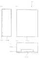
図2(a)は本実施の形態における光接続箱11の側面図、同図(b)は正面図、同図(c)は底面図である。 2A is a side view of the
光接続箱11は、平板状の樹脂製ボデー11aに箱状の樹脂製カバー11bが被されて構成されている。その外形寸法は高さ(縦)450mm、幅(横)350mm、奥行き(厚さ)160mmであり、カバー11bの底面には開口部11cが設けられている。この開口部11cは、光接続箱11内に導入される外線光ファイバケーブルの導入部、および光接続箱11から導出される構内光ファイバコードの導出部となる。 The
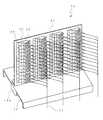
図3(a)は、カバー11bを外した状態の光接続箱11の正面図、同図(b)はその右側面図である。 FIG. 3A is a front view of the
ボデー11aの表面には外周が一回り小さな金属製のベース板12が設けられており、このベース板12の下方寄りには融着接続ユニット13、上方にはコネクタ接続ユニット14が設けられている。融着接続ユニット13およびコネクタ接続ユニット14はそれぞれ引出式テーブル15および16上に取り付けられており、引き手部15aおよび16bに手を掛けてベース板12の板面に垂直な方向に自在に引き出すことが可能になっている。同図(b)に点線で示す引出式テーブル15および16はベース板12から引き出された状態を示している。 A
ベース板12の矩形状に切り欠かれた下端には、開口部11cを経由して外線光ファイバケーブル17が導入される。本実施形態では、外線光ファイバケーブル17は、テンションメンバの周りのスペーサ溝内に4心テープ心線が複数収納されたテープスロット型が用いられており、外線光ファイバケーブル17から12本の4心テープ心線18で合計48心の光ファイバコードが取り出される。取り出された4心テープ心線18は、融着接続ユニット13を構成する2枚のスプライストレイ13aにおいて、融着接続ユニット13とコネクタ接続ユニット14との間の中継用として事前に光接続箱11に配線されている4心FO(ファンアウト)コード19の一端と融着接続される。この融着接続の際には、融着接続ユニット13は引出式テーブル15によって同図(b)に点線で示す位置に引き出され、スプライストレイ13aの蓋が同図に点線で示すように開けられる。一方のスプライストレイ13aには7本の4心テープ心線18が導かれて28心の光ファイバ融着接続部が収納され、他方のスプライストレイ13aには5本の4心テープ心線18が導かれて20心の光ファイバ融着接続部が収納される。 An external
一端が融着接続された4心FOコード19は合計で48心がコードトレイ21を経由してコネクタ接続ユニット14へ予め導かれている。4心FOコード19の他端にはSC形の光コネクタプラグ20が取り付けられており、合計で48個の光コネクタプラグ20は光パッチパネル22に取り付けられた合計で48個のSC形単心光コネクタアダプタ23の一方の側に予め差し込まれている。光パッチパネル22は、光コネクタアダプタ23と共にコネクタ接続ユニット14を構成しており、金属製の板の下端がLの字型に折り曲げられて形成され、折り曲げ部が引出式テーブル16に固定されている。光コネクタアダプタ23は、同図(b)に示すように、12個が1列とされて奥行き方向に4列に合計48個配置されており、図1に示す従来の24個の場合と比べて高密度化されている。この光コネクタアダプタ23の他方の側には、同図(a)に点線で示す構内光ファイバコード24の一端に取り付けられたSC形の光コネクタプラグ25が差し込まれる。光パッチパネル22は、光接続箱11内において光コネクタプラグ20,25同士を光コネクタアダプタ23を介して接続し、構内光ファイバコード24はFOコード19とコネクタ接続される。このコネクタ接続により、構内光ファイバコード24は、FOコード19を介して外線光ファイバケーブル17内のテープ心線18と光接続されることになる。一端が光コネクタアダプタ23に差し込まれた構内光ファイバコード24の他端側はベース板12の下端側に引き回され、開口部11cを経由して光接続箱11の外へ導かれ、構内に設けられた光機器に配線接続される。 A total of 48 cores of the four-
図4は、光パッチパネル22に設けられた光コネクタアダプタ23に構内光ファイバコード24の光コネクタプラグ25が差し込まれた状態を示す斜視図である。なお、同図において図3と同一または相当する部分には同一符号を付してその説明は省略する。 FIG. 4 is a perspective view showing a state where the optical connector plug 25 of the local
光パッチパネル22には図示しない長穴状の開口部が上下方向に4列に平行に並んで形成されている。各開口部の高さ方向の寸法は、パネル取付タイプの単心光コネクタアダプタ23を12個積層した高さ寸法よりも若干大きく、各開口部で等しく設定されている。従って、48個の単心光コネクタアダプタ23は各開口部に列方向に遊びをもって12個ずつ嵌められて、4列に積層される。光パッチパネル22のパネル面には、1〜12、13〜24、25〜36、および37〜48のアダプタ識別番号がそれぞれ光コネクタアダプタ23の各列方向に沿って記されたナンバーラベル26が貼られている。 The
図5(a)は本実施の形態のアダプタ識別治具31の平面図、同図(b)はその側面図である。 FIG. 5A is a plan view of the
アダプタ識別治具31は、本実施の形態では縦140mm、横45mmで0.5mm厚の長方形状のアルミニウム板からなる。アダプタ識別治具31の厚さは、光コネクタアダプタ23が嵌められる開口部の高さ寸法に応じて、アダプタ識別治具31が各コネクタアダプタ23間にしっかり挟まる厚さに設計される。アダプタ識別治具31の板面にはナンバーラベル32が貼られている。ナンバーラベル32には、光コネクタアダプタ23の識別番号が光コネクタアダプタ23の積層位置に対応して記されており、アダプタ識別治具31の板面には、光コネクタアダプタ23の識別番号が光コネクタアダプタ23の積層位置に対応して表されている。 In this embodiment, the
アダプタ識別治具31は、図4に示すように積層された任意の光コネクタアダプタ23間の隙間に図6に示すように各列にわたって挿入されて、各列を分断する。なお、図6において図4と同一または相当する部分には同一符号を付してその説明は省略する。そして、アダプタ識別治具31は、分断した箇所の板面に沿って並ぶ各光コネクタアダプタ23同士の位置関係を後述するように識別させる。また、図5に示すように、アダプタ識別治具31には長穴状の窓33が形成されている。窓33は、アダプタ識別治具31が各列にわたって挿入されて各列を分断した際に、アダプタ識別治具31の板面に隠れる光パッチパネル22のパネル面を図7の一部斜視図に示すように臨ます。なお、図7において図5および図6と同一または相当する部分には同一符号を付してその説明は省略する。また、アダプタ識別治具31の右肩には丸穴34が形成されている。この丸穴34は、アダプタ識別治具31をフックなどに引っ掛けて保管しておく際や、紐を通して作業者の首にアダプタ識別治具31をぶら下げておく際などに、使用される。 The
このような本実施の形態によれば、上記のように、単心の光コネクタアダプタ23が、光パッチパネル22に4列に並んで形成された各開口部に列方向に遊びをもって嵌められて、図4に示すように4列に積層される。従って、各光コネクタアダプタ23は積層された各開口部において列方向に遊動し、図5に示すように板状をしたアダプタ識別治具31を、積層された任意の光コネクタアダプタ23間に図6に示すように各列にわたって挿入することが出来る。このため、本実施の形態のように、光コネクタアダプタ23の列が光接続箱11の手前から奥行き方向に順に配置され、光コネクタプラグ25の挿抜方向が光接続箱11の幅方向とされている場合、光パッチパネル22に設けられる光コネクタアダプタ23および光ファイバコード24が多くても、光接続箱11の手前側のアダプタ識別番号1〜12を容易に目視確認することが出来る最前列の任意の光コネクタアダプタ23間に、板状をしたアダプタ識別治具31の手前側の長手方向端部を押し込み、その状態でアダプタ識別治具31の奥側の長手方向端部を奥側の列の光コネクタアダプタ23間に押し込むことで、積層された任意の光コネクタアダプタ23間に各列にわたってアダプタ識別治具31を挿入して各列を分断することが出来る。 According to the present embodiment, as described above, the single
奥側の列にある光コネクタアダプタ23は、分断した箇所のアダプタ識別治具31の板面に沿って並ぶ各光コネクタアダプタ23同士の位置関係を識別することで、特定することが可能である。つまり、分断した箇所のアダプタ識別治具31の板面に沿って並ぶ光コネクタアダプタ23のうち、手前側にある光コネクタアダプタ23はその1〜12のアダプタ識別番号を容易に目視確認することが出来るため、該当する行の光コネクタアダプタ23のアダプタ識別番号を事前に確認しておけば、各列に配置されている各光コネクタアダプタ23間の関係に基づいて、アダプタ識別番号を把握できる手前側にある光コネクタアダプタ23との関係から、奥側の列にある光コネクタアダプタ23を特定することが出来る。例えば、図6に示すように、アダプタ識別番号が8と9の間の最前列の光コネクタアダプタ23間にアダプタ識別治具31の手前側の長手方向端部を押し込んだ場合、各列に配置されている各光コネクタアダプタ23間の予め認識している関係に基づいて、分断した箇所のアダプタ識別治具31の板面に沿って行方向に並ぶ2列目の光コネクタアダプタ23のアダプタ識別番号は20、3列目の光コネクタアダプタ23のアダプタ識別番号は32、そして4列目の光コネクタアダプタ23のアダプタ識別番号は44と識別することが出来る。 The
よって、光コネクタアダプタ23の列が光接続箱11の手前から奥行き方向に順に配置され、光パッチパネル22に設けられる光コネクタアダプタ23および光ファイバコード24が多い場合でも、挿抜作業の対象とする光コネクタアダプタ23を容易にかつ確実に特定することが可能になる。例えば、上記の例で、アダプタ識別番号が44の光コネクタアダプタ23を特定するには、アダプタ識別番号が8と9の間の最前列の光コネクタアダプタ23間にアダプタ識別治具31を挿入することで、分断した箇所のアダプタ識別治具31の板面に沿って並ぶ4列目の光コネクタアダプタ23が該当するものと特定することが出来る。 Therefore, even when the row of
しかも、アダプタ識別治具31によって分断された下方の光コネクタアダプタ23群および光ファイバコード24群がアダプタ識別治具31に隠れて触れなくなるので、光コネクタプラグ25の挿抜時に作業対象でない光コネクタプラグ25を誤って掴むおそれが低減され、また、作業対象でない光コネクタアダプタ23群および光ファイバコード24群によって光コネクタプラグ25の挿抜作業が邪魔されなくなる。この結果、光コネクタプラグ25の挿抜作業の作業性は向上する。また、光コネクタアダプタ23が多数配置されても各光コネクタアダプタ23を識別することが可能なことから、光パッチパネル22、ひいては光接続箱11をより小型にすることが可能となる。また、アダプタ識別治具31は単に板状をした部材によって構成されるため、その製作にかかる費用は低減される。 In addition, since the lower
また、本実施の形態によれば、各列にわたって挿入されて各列を分断した際にアダプタ識別治具31の板面に隠れる光パッチパネル22のパネル面は、図7に示すように、アダプタ識別治具31に形成された窓33から視認される。このため、分断した箇所のアダプタ識別治具31の板面に沿って並ぶ各光コネクタアダプタ23同士の位置関係に加え、アダプタ識別治具31の窓33から視認される光パッチパネル22のパネル面に取り付けられた光コネクタアダプタ23との位置関係も把握される。例えば、上記の例では、分断した箇所のアダプタ識別治具31の板面に沿って並ぶ各光コネクタアダプタ23同士のアダプタ識別番号が8,20,32,44であるという位置関係に加え、アダプタ識別治具31の窓33から視認される、アダプタ識別治具31で分断された2列目の光コネクタアダプタ23の下方にある光コネクタアダプタ23のアダプタ識別番号が21であるという位置関係からも、アダプタ識別治具31によって分断された2列目の光コネクタアダプタ23のアダプタ識別番号が20であるということが把握される。このため、窓33がアダプタ識別治具31に形成された本実施の形態によれば、作業対象とする光コネクタアダプタ23の特定がより容易に行える。 Further, according to the present embodiment, the panel surface of the
また、本実施の形態によれば、アダプタ識別番号を把握できる手前側にある例えばアダプタ識別番号8の光コネクタアダプタ23との関係から、奥側の列にある例えばアダプタ識別番号20,32,44の光コネクタアダプタ23を特定する際、アダプタ識別治具31に貼られているナンバーラベル32を参照することで、各列に配置されている各光コネクタアダプタ23間の関係に基づいて、容易に奥側の列にある光コネクタアダプタ23を特定することが出来る。つまり、光コネクタアダプタ23の積層位置に対応してナンバーラベル32に図5に示すように表されている例えばアダプタ識別番号8の行の表示「8 20 32 44」を参照することで、容易に、アダプタ識別番号8の光コネクタアダプタ23の奥側のアダプタ識別治具31の板面に沿って並ぶ光コネクタアダプタ23のアダプタ識別番号が20,32,44であることを特定することが出来る。 Further, according to the present embodiment, for example, the
また、本実施の形態によれば、光接続箱11内の光パッチパネル22における光コネクタアダプタ23を容易にかつ確実に特定することが可能なアダプタ識別治具31が提供される。 Moreover, according to this Embodiment, the adapter identification jig |
なお、本実施の形態では、アダプタ識別治具31をアルミニウム板から形成した場合について説明したが、材質はこれに限定されるものではなく、例えば樹脂板によって形成するようにしてもよい。樹脂板によって形成すると、アダプタ識別治具31を光コネクタアダプタ23間に挿入する際、光コネクタアダプタ23に傷が付くのを防止することが出来る。また、最前列から奥側に取り付けた光コネクタアダプタ23の配置を表すアダプタ識別番号の対応表をナンバーラベル32に記載し、これをアダプタ識別治具31に貼るように構成したが、アダプタ識別治具31の板面にアダプタ識別番号の対応表を印刷や刻印などで直接記載するように構成してもよい。 In the present embodiment, the case where the
上記の実施の形態では、本発明によるアダプタ識別治具31を光接続箱11内の光パッチパネル22における光コネクタアダプタ23の識別に用いたが、本発明はこれに限定されるものではなく、光コネクタアダプタ23が取り付けられた光パッチパネル22を含む製品全般に適用することが可能である。そして、その場合においても、上記の実施形態と同様な作用効果が奏される。 In the above embodiment, the
11…光接続箱
11a…ボデー
11b…カバー
11c…開口部
12…ベース板
13…融着接続ユニット
14…コネクタ接続ユニット
15,16…引出式テーブル
15a,16a…引き手部
17…外線光ファイバケーブル
18…4心テープ心線
19…4心FOコード
20,25…光コネクタプラグ
21…コードトレイ
22…光パッチパネル
23…光コネクタアダプタ
24…構内光ファイバコード
26,32…ナンバーラベル
31…アダプタ識別治具
33…窓
34…丸穴DESCRIPTION OF
Claims (4)
Translated fromJapanese板状をしており、積層された任意の前記光コネクタアダプタ間に各前記列にわたって挿入されて各前記列を分断し、分断した箇所の板面に沿って並ぶ各前記光コネクタアダプタ同士の位置関係を識別させる
ことを特徴とするアダプタ識別治具。An adapter identification jig for identifying single-core optical connector adapters that are fitted with play in the row direction in the openings formed in a plurality of rows on the optical patch panel and stacked in a plurality of rows,
The positions of the optical connector adapters that are plate-shaped and that are inserted between the stacked optical connector adapters across the rows to divide the rows and that are lined up along the plate surfaces of the divided locations. Adapter identification jig characterized by identifying relationships.
Priority Applications (1)
| Application Number | Priority Date | Filing Date | Title |
|---|---|---|---|
| JP2011172913AJP2013037173A (en) | 2011-08-08 | 2011-08-08 | Adapter identifying jig |
Applications Claiming Priority (1)
| Application Number | Priority Date | Filing Date | Title |
|---|---|---|---|
| JP2011172913AJP2013037173A (en) | 2011-08-08 | 2011-08-08 | Adapter identifying jig |
Publications (1)
| Publication Number | Publication Date |
|---|---|
| JP2013037173Atrue JP2013037173A (en) | 2013-02-21 |
Family
ID=47886828
Family Applications (1)
| Application Number | Title | Priority Date | Filing Date |
|---|---|---|---|
| JP2011172913APendingJP2013037173A (en) | 2011-08-08 | 2011-08-08 | Adapter identifying jig |
Country Status (1)
| Country | Link |
|---|---|
| JP (1) | JP2013037173A (en) |
Cited By (2)
| Publication number | Priority date | Publication date | Assignee | Title |
|---|---|---|---|---|
| JP2013158126A (en)* | 2012-01-30 | 2013-08-15 | Chugoku Electric Power Co Inc:The | Lan cable work zoning jig |
| US11543612B2 (en) | 2018-10-24 | 2023-01-03 | Nippon Telegraph And Telephone Corporation | Connector plug, connector insertion method, and a connector removal method |
Citations (5)
| Publication number | Priority date | Publication date | Assignee | Title |
|---|---|---|---|---|
| JP2000241631A (en)* | 1999-02-19 | 2000-09-08 | Fujikura Ltd | Optical module and optical distribution frame |
| JP2004138641A (en)* | 2002-10-15 | 2004-05-13 | Fujikura Ltd | Optical connection unit |
| JP2008258440A (en)* | 2007-04-05 | 2008-10-23 | Toshiba Corp | Electronics |
| JP2010091695A (en)* | 2008-10-07 | 2010-04-22 | Yazaki Corp | Optical splice unit |
| JP2010096835A (en)* | 2008-10-14 | 2010-04-30 | Sumiden High Precision Co Ltd | Cable retreating method and tool thereof |
- 2011
- 2011-08-08JPJP2011172913Apatent/JP2013037173A/enactivePending
Patent Citations (5)
| Publication number | Priority date | Publication date | Assignee | Title |
|---|---|---|---|---|
| JP2000241631A (en)* | 1999-02-19 | 2000-09-08 | Fujikura Ltd | Optical module and optical distribution frame |
| JP2004138641A (en)* | 2002-10-15 | 2004-05-13 | Fujikura Ltd | Optical connection unit |
| JP2008258440A (en)* | 2007-04-05 | 2008-10-23 | Toshiba Corp | Electronics |
| JP2010091695A (en)* | 2008-10-07 | 2010-04-22 | Yazaki Corp | Optical splice unit |
| JP2010096835A (en)* | 2008-10-14 | 2010-04-30 | Sumiden High Precision Co Ltd | Cable retreating method and tool thereof |
Cited By (2)
| Publication number | Priority date | Publication date | Assignee | Title |
|---|---|---|---|---|
| JP2013158126A (en)* | 2012-01-30 | 2013-08-15 | Chugoku Electric Power Co Inc:The | Lan cable work zoning jig |
| US11543612B2 (en) | 2018-10-24 | 2023-01-03 | Nippon Telegraph And Telephone Corporation | Connector plug, connector insertion method, and a connector removal method |
Similar Documents
| Publication | Publication Date | Title |
|---|---|---|
| JP3989853B2 (en) | Optical connection unit | |
| US7961999B2 (en) | Optical waveguide distribution device | |
| JP2006227041A (en) | Optical fiber storage tray drawing position lock structure, optical fiber storage unit, and optical distribution board | |
| US10101551B2 (en) | Multi-core/single-core conversion module and multi-core/single-core conversion apparatus | |
| JP6934773B2 (en) | How to replace optical wiring using a termination unit | |
| JP2013037173A (en) | Adapter identifying jig | |
| JP2008224998A (en) | Optical cable connection closure and optical wiring system | |
| JP3698579B2 (en) | Optical fiber alignment board | |
| JP5671756B2 (en) | Panel for optical wiring | |
| JP4159977B2 (en) | Optical module | |
| US9423571B2 (en) | Optical connector protecting cap, optical fiber cable with connector cap, and cap removal tool | |
| US11953736B2 (en) | Fiber connection structure with optical connector, and module | |
| JP2001194536A (en) | Optical connection box and optical connection method | |
| JP5072610B2 (en) | Optical connector cover and optical wiring board using optical connector cover | |
| JP3065295U (en) | Optical fiber connection storage tray and optical fiber connection storage unit | |
| JP3204959U (en) | Optical cable holding member and optical cable holding unit | |
| US20230213720A1 (en) | Optical fiber distribution device with identifiers | |
| JP2004138642A (en) | Optical connection unit | |
| JP4209836B2 (en) | closure | |
| JP5406091B2 (en) | Optical fiber holder | |
| JP4745200B2 (en) | Module storage shelf in optical cable connection storage cabinet | |
| JP3909546B2 (en) | Extra length storage tray, optical connection to it, and extra length storage method | |
| CN104656214B (en) | Kit for manufacturing optical waveguide-coupling arrangement | |
| KR20090069790A (en) | Optical cable connection tube | |
| JP5675557B2 (en) | Optical fiber cable and optical fiber cable branching method |
Legal Events
| Date | Code | Title | Description |
|---|---|---|---|
| A621 | Written request for application examination | Free format text:JAPANESE INTERMEDIATE CODE: A621 Effective date:20140627 | |
| A131 | Notification of reasons for refusal | Free format text:JAPANESE INTERMEDIATE CODE: A131 Effective date:20150707 | |
| A02 | Decision of refusal | Free format text:JAPANESE INTERMEDIATE CODE: A02 Effective date:20151222 |