JP2013034547A - Endoscope - Google Patents
EndoscopeDownload PDFInfo
- Publication number
- JP2013034547A JP2013034547AJP2011171185AJP2011171185AJP2013034547AJP 2013034547 AJP2013034547 AJP 2013034547AJP 2011171185 AJP2011171185 AJP 2011171185AJP 2011171185 AJP2011171185 AJP 2011171185AJP 2013034547 AJP2013034547 AJP 2013034547A
- Authority
- JP
- Japan
- Prior art keywords
- rod member
- traction
- pair
- bending
- endoscope
- Prior art date
- Legal status (The legal status is an assumption and is not a legal conclusion. Google has not performed a legal analysis and makes no representation as to the accuracy of the status listed.)
- Granted
Links
Images


Classifications
- A—HUMAN NECESSITIES
- A61—MEDICAL OR VETERINARY SCIENCE; HYGIENE
- A61B—DIAGNOSIS; SURGERY; IDENTIFICATION
- A61B1/00—Instruments for performing medical examinations of the interior of cavities or tubes of the body by visual or photographical inspection, e.g. endoscopes; Illuminating arrangements therefor
- A61B1/00064—Constructional details of the endoscope body
- A61B1/00071—Insertion part of the endoscope body
- A61B1/00078—Insertion part of the endoscope body with stiffening means
Landscapes
- Health & Medical Sciences (AREA)
- Life Sciences & Earth Sciences (AREA)
- Surgery (AREA)
- Biomedical Technology (AREA)
- Medical Informatics (AREA)
- Optics & Photonics (AREA)
- Pathology (AREA)
- Radiology & Medical Imaging (AREA)
- Biophysics (AREA)
- Engineering & Computer Science (AREA)
- Physics & Mathematics (AREA)
- Heart & Thoracic Surgery (AREA)
- Nuclear Medicine, Radiotherapy & Molecular Imaging (AREA)
- Molecular Biology (AREA)
- Animal Behavior & Ethology (AREA)
- General Health & Medical Sciences (AREA)
- Public Health (AREA)
- Veterinary Medicine (AREA)
- Instruments For Viewing The Inside Of Hollow Bodies (AREA)
- Endoscopes (AREA)
Abstract
Translated fromJapaneseDescription
Translated fromJapanese本発明は、挿入部内に、第1機能部である湾曲部を湾曲するための湾曲部操作用ワイヤーと、該湾曲操作用ワイヤーの他に牽引することによって第2機能部を動作させる第2機能部操作用ワイヤーとを備える内視鏡に関する。 The present invention provides a bending portion operating wire for bending the bending portion, which is the first functional portion, in the insertion portion, and a second function for operating the second functional portion by pulling in addition to the bending operation wire. The present invention relates to an endoscope including a wire for operation of a part.
近年、医療分野において、体内に細長の挿入部を挿入することにより、観察、或いは各種治療処置を行える内視鏡が利用されている。 2. Description of the Related Art In recent years, endoscopes that can perform observation or various treatments by inserting an elongated insertion portion into the body have been used in the medical field.
内視鏡には、挿入部が軟性な内視鏡の挿入部先端側に例えば上下左右方向に湾曲する湾曲部を備えた湾曲部付内視鏡、或いは湾曲部の湾曲半径を例えば第1の半径と第2の半径と切り替え可能な湾曲部湾曲半径可変内視鏡、或いは挿入部の先端部の内部に設けられた撮像光学系の観察範囲を広角又は拡大に切り替えることが可能なズーム機能付き内視鏡、或いは挿入部を構成する可撓管部の硬度を可変することが可能な硬度可変内視鏡等が知られている。 In the endoscope, the endoscope with a bending portion provided with a bending portion that bends in the vertical and horizontal directions on the distal end side of the insertion portion of the endoscope having a flexible insertion portion, or the bending radius of the bending portion, for example, With a zoom function capable of switching the observation range of the imaging optical system provided in the distal end of the insertion portion or the bending radius variable endoscope that can be switched between the radius and the second radius to a wide angle or an enlargement. Endoscopes or variable hardness endoscopes that can change the hardness of a flexible tube part that constitutes an insertion part are known.
湾曲部付内視鏡では、挿入部の基端に配設された操作部に湾曲部操作装置が設けられ、挿入部内には先端が湾曲部に固定された湾曲部操作用ワイヤーが挿通されている。この内視鏡では、湾曲部操作装置を操作して湾曲部操作用ワイヤーを牽引・弛緩することにより、湾曲部の湾曲操作を行える。 In an endoscope with a bending portion, a bending portion operating device is provided at an operation portion disposed at a proximal end of the insertion portion, and a bending portion operation wire having a distal end fixed to the bending portion is inserted into the insertion portion. Yes. In this endoscope, the bending portion can be bent by operating the bending portion operating device to pull and relax the bending portion operating wire.
これに対して、湾曲部湾曲半径可変内視鏡、ズーム機能付き内視鏡、及び硬度可変内視鏡等においては、操作部に湾曲部操作用ワイヤー(第1操作用ワイヤー)を牽引・弛緩するための湾曲部操作装置(第1操作装置)の他に、挿入部内に湾曲部操作用ワイヤーの他に挿通されている第2操作用ワイヤーを牽引するための第2操作装置が設けられている。 On the other hand, in a bending portion bending radius variable endoscope, an endoscope with a zoom function, and a hardness variable endoscope, a bending portion operation wire (first operation wire) is pulled and relaxed in the operation portion. In addition to the bending portion operating device (first operating device), a second operating device for pulling the second operating wire inserted in addition to the bending portion operating wire is provided in the insertion portion. Yes.
具体的に、湾曲部湾曲半径可変内視鏡においては、挿入部内に第2操作用ワイヤーとして湾曲部の一部である例えば湾曲部基端側を湾曲可能な状態と湾曲不能な状態とに切り替えるための湾曲半径切替ワイヤーが挿通される。そして、操作部には湾曲半径切替ワイヤーを牽引弛緩するための湾曲部半径切替操作装置が第2操作装置として設けられる。この湾曲部湾曲半径可変内視鏡では、湾曲部半径切替操作装置を操作することなく湾曲半径切替ワイヤーを牽引していない状態、即ち、該切替ワイヤーが弛緩した状態において、湾曲部操作装置を操作して湾曲部操作用ワイヤーを牽引、弛緩操作することにより、湾曲部先端側と湾曲部の湾曲部基端側とを備える湾曲部全体が半径Rで湾曲する。一方、この内視鏡では、湾曲部半径切替操作装置によって湾曲半径切替ワイヤーを牽引することにより、湾曲部基端側が湾曲不能な状態なる。ここで、その状態を保持しつつ、湾曲部操作装置を操作して湾曲部操作用ワイヤーを牽引、弛緩操作する。すると、湾曲部の湾曲部基端側が湾曲不能な状態に保持されているため、湾曲部操作用ワイヤーの牽引、弛緩によって、湾曲部の湾曲部先端側だけが半径Rより小さな半径で湾曲する。 Specifically, in the bending portion bending radius variable endoscope, as the second operation wire in the insertion portion, for example, the bending portion proximal end side is switched between a bendable state and a non-bendable state. For this purpose, a bending radius switching wire is inserted. The operation portion is provided with a bending portion radius switching operation device as a second operation device for pulling and relaxing the bending radius switching wire. In this bending portion variable curvature radius endoscope, the bending portion operating device is operated in a state where the bending radius switching wire is not pulled without operating the bending portion radius switching operation device, that is, in a state where the switching wire is relaxed. Then, by pulling and relaxing the bending portion operating wire, the entire bending portion including the bending portion distal end side and the bending portion proximal end side of the bending portion is bent at the radius R. On the other hand, in this endoscope, the bending portion proximal end side cannot be bent by pulling the bending radius switching wire by the bending portion radius switching operation device. Here, while the state is maintained, the bending portion operating device is operated to pull and relax the bending portion operating wire. Then, since the bending portion proximal end side of the bending portion is held in a state where it cannot be bent, only the distal end side of the bending portion of the bending portion is bent with a radius smaller than the radius R by pulling and relaxation of the bending portion operation wire.
また、ズーム機能付き内視鏡では、操作部に第2操作装置として移動レンズ操作装置を備え、挿入部内には第2操作用ワイヤーとして移動レンズ操作用ワイヤーが挿通されている。このズーム機能付き内視鏡では、例えば、移動レンズ操作装置の操作によって移動レンズ操作用ワイヤーを牽引して、移動レンズが配置された移動レンズ枠を軸方向に後退させることによって観察部位の広角画像が拡大画像に切り替えられるようになっている。 In the endoscope with a zoom function, the operation unit includes a moving lens operation device as a second operation device, and a movement lens operation wire is inserted into the insertion portion as a second operation wire. In this endoscope with a zoom function, for example, a moving lens operating wire is pulled by operating a moving lens operating device, and a moving lens frame on which the moving lens is arranged is retracted in the axial direction, thereby wide-angle image of an observation site. Can be switched to an enlarged image.
また、硬度可変内視鏡では、操作部に第2操作装置として硬度可変操作装置を設け、挿入部内には第2操作用ワイヤーとして硬度調整用ワイヤーが設けられている。硬度調整用ワイヤーは、挿入部を構成する可撓管部内に配設されたコイルパイプ内に挿通され、コイルパイプの先端が硬度調整ワイヤーの途中の固定部において強固に固定されている。この硬度可変内視鏡では、硬度可変操作装置によって硬度調整用ワイヤーを牽引してコイルパイプを圧縮して該パイプの硬度を増大させることによって可撓管部を硬くすることができるようになっている。 In the variable hardness endoscope, a variable hardness operating device is provided as the second operating device in the operating portion, and a hardness adjusting wire is provided as the second operating wire in the insertion portion. The hardness adjusting wire is inserted into a coil pipe disposed in a flexible tube portion constituting the insertion portion, and the tip of the coil pipe is firmly fixed at a fixing portion in the middle of the hardness adjusting wire. In this variable hardness endoscope, the flexible pipe portion can be hardened by pulling the hardness adjusting wire with the hardness variable operating device and compressing the coil pipe to increase the hardness of the pipe. Yes.
例えば、特許文献1には、挿入部内に挿通された硬度調整ワイヤーを、操作部の前端に設けた円筒形状の硬度調整ノブを回動操作することによって牽引・弛緩することにより、該ワイヤーの外周に被覆されたコイルパイプの圧縮、非圧縮に伴い、挿入部の可撓管部の硬度を可変させる構成の内視鏡が開示されている。そして、この内視鏡では、硬度調整ノブを手で回転操作して可撓管部の硬度を硬くする操作を行った状態で、硬度調整ノブから手を離しても、硬度調整ノブがその操作状態にロックされることにより、その操作状態に対応する硬度状態でコイルをロックできる構造になっている。 For example,
また、特許文献2には、挿入部内に挿通された操作ワイヤーを、操作部に設けられたレバーを回動操作することによって操作ワイヤーを牽引して該ワイヤーの外周に被覆された密着コイルの圧縮、非圧縮に伴い、挿入部の可撓管部の硬度を可変させる構成の内視鏡が開示されている。この内視鏡には、操作ワイヤーの牽引状態を保持すること、及びその保持状態を解除することのできるロック機構がレバーとは別に設けられている。 Further, in
しかしながら、特許文献1の内視鏡では、術者が硬度調整ワイヤーの牽引、保持、保持解除、弛緩を行う際、挿入部を把持している手をいったん離し、その手で操作部に設けられている硬度調整ノブの回動操作を行う必要があった。 However, in the endoscope of
一方、特許文献2の内視鏡では、操作ワイヤーの牽引・弛緩を行うレバーと、牽引保持、牽引解除を行うロック機構とが別に設けられているため操作が煩雑で、状況によっては挿入部を把持している手をいったん離し、その手でロック機構の操作を行う必要が生じるおそれがあった。 On the other hand, in the endoscope of
本発明は、上記事情に鑑みなされたものであって、挿入部を把持している手を該挿入部から離すことなく、操作部を把持している手で挿入部内に挿通されている第2操作用ワイヤーの牽引、保持、保持解除、弛緩の操作を行える第2操作装置を該操作部に湾曲部操作装置の他に備えた内視鏡を提供することを目的にしている。 The present invention has been made in view of the above circumstances, and the second hand inserted into the insertion part with the hand holding the operation part without releasing the hand holding the insertion part from the insertion part. It is an object of the present invention to provide an endoscope provided with a second operating device capable of pulling, holding, releasing, and relaxing an operation wire in addition to a bending portion operating device.
本発明の一態様の内視鏡は、先端側から順に、先端部、湾曲部、及び可撓管部を連設して構成される挿入部と、前記湾曲部を湾曲させる第1牽引部材の基端が固定され、回動することで該第1牽引部材を牽引あるいは弛緩する第1牽引操作装置、及び回動自在に設けられ前記第1牽引部材とは異なる第2牽引部材を牽引する際に操作される第2牽引操作装置を備える、前記挿入部の基端側に設けられた把持部を兼ねる操作部と、前記操作部内に進退自在に配置され、前記第2牽引操作装置を初期位置から一方向に回転させることによって操作部長手軸の第1方向に移動し、該第2牽引操作装置を初期位置に戻すように他方向に回転させることによって前記第1方向とは逆方向である第2方向に移動する、前記第2牽引部材の基端が固定されるロッド部材と、前記操作部内の予め定めた位置に固設され、前記ロッド部材の第1方向への移動及び第2方向への移動によって、該操作部長手軸方向に対して直交する拡がる方向、及び縮まる方向に弾性変形可能で前記ロッド部材の前記操作部長手軸方向の位置を保持するための位置決め面を有する一対の当接部を有する弾性部材と、を備え、前記ロッド部材は、軸本体と、該軸本体に基端側から順に固設される、前記ロッド部材の基端面側に設けられ、前記ロッド部材と前記第2牽引操作装置とを連結する連結部材が取りつけられる取付部と、前記取付部より前記ロッド部材の先端側に設けられ、該ロッド部材の第1方向への移動に伴って前記一対の当接部を徐々に拡げる拡径傾斜面および前記弾性部材の位置決め面に当接する保持平面を備える第1凸部と、前記第1凸部より前記ロッド部材の先端側に設けられ、該ロッド部材の第1方向への移動に伴って前記弾性部を徐々に縮める一対の第1傾斜面、前記ロッド部材の更なる第1方向への移動に伴って前記第1傾斜面によって縮められた前記一対の当接部が通過可能なスリット、および当該ロッド部材の第2方向への移動に伴って前記一対の当接部を徐々に拡げる一対の第2傾斜面を備える第2凸部と、前記ロッド部材の先端面側に設けられ、前記第2牽引部材の基端が固定されるワイヤー固定部と、を具備している。 An endoscope according to an aspect of the present invention includes, in order from the distal end side, an insertion portion configured by connecting a distal end portion, a bending portion, and a flexible tube portion, and a first traction member that bends the bending portion. A first traction operation device that pulls or relaxes the first traction member by fixing the base end and rotating, and a second traction member that is rotatably provided and is different from the first traction member. And a second pulling operation device that is operated at a base end side of the insertion portion, and an operation portion that also serves as a gripping portion, and is disposed in the operation portion so as to be able to advance and retract. The first pulling operation device is moved in the first direction by rotating in one direction, and the second pulling operation device is rotated in the other direction so as to return to the initial position, and is opposite to the first direction. The base end of the second pulling member that moves in the second direction is fixed. And a direction in which the rod member extends in a direction perpendicular to the longitudinal direction of the operating portion by moving the rod member in the first direction and moving in the second direction. And an elastic member having a pair of abutting portions that are elastically deformable in a contracting direction and have a positioning surface for holding the position of the rod member in the longitudinal direction of the operation portion, the rod member having a shaft A main body and an attachment portion fixed to the shaft main body in order from the base end side, provided on the base end surface side of the rod member, and attached to a connecting member for connecting the rod member and the second traction operation device; A diameter-increasing inclined surface that is provided on the distal end side of the rod member from the mounting portion and gradually expands the pair of contact portions as the rod member moves in the first direction, and a positioning surface of the elastic member The holding plane that abuts And a pair of first inclined surfaces that are provided closer to the distal end side of the rod member than the first convex portion and gradually contract the elastic portion as the rod member moves in the first direction, As the rod member further moves in the first direction, a slit through which the pair of contact portions contracted by the first inclined surface can pass, and as the rod member moves in the second direction. A second convex portion having a pair of second inclined surfaces that gradually expand the pair of contact portions, and a wire fixing portion that is provided on the distal end surface side of the rod member and to which the proximal end of the second pulling member is fixed And.
本発明によれば、挿入部を把持している手を該挿入部から離すことなく、操作部を把持している手で挿入部内に挿通されている第2操作用ワイヤーの牽引、保持、保持解除、弛緩の操作を行える第2操作装置を該操作部に湾曲部操作装置の他に備えた内視鏡を実現できる。 According to the present invention, the second operation wire inserted into the insertion portion by the hand holding the operation portion is pulled, held, and held without releasing the hand holding the insertion portion from the insertion portion. It is possible to realize an endoscope provided with a second operating device capable of releasing and relaxing in addition to the bending portion operating device.
図1−図18を参照して本発明の一実施形態を説明する。
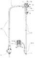
図1に示すように内視鏡1は、挿入部2と、操作部3と、ユニバーサルコード4とを備えて構成されている。ユニバーサルコード4は、操作部3の側部から延出しており、その延出端にはコネクター5が設けられている。コネクター5は、外部装置である図示しない制御装置および照明装置等に電気的に接続される。An embodiment of the present invention will be described with reference to FIGS.
As shown in FIG. 1, the
挿入部2は、先端側から順に、先端部11、湾曲部12、および可撓管部13を連設して構成されている。
先端部11には観察光学系が設けられている。観察光学系は、観察部位を照明する図示しない照明ユニットおよび照明ユニットに照明された観察部位を撮像する撮像ユニット(不図示)を備えて構成されている。The
The distal end portion 11 is provided with an observation optical system. The observation optical system includes an illumination unit (not shown) that illuminates the observation site and an imaging unit (not shown) that images the observation site illuminated by the illumination unit.
湾曲部12は、内視鏡の第1機能部であって複数の湾曲駒14を回動自在に連結して、例えば上下左右の四方向に湾曲するように構成されている。湾曲部12を構成する複数の湾曲駒14のうち、最先端に位置する先端湾曲駒14fには、第1牽引部材として4本の湾曲ワイヤー15U、15D、15L、15Rのそれぞれの先端が予め定めた位置に固定されている。4本の湾曲ワイヤー15U、15D、15L、15Rは、第1機能部操作用のワイヤーであり、本実施形態においては、上下左右の四方向に対応して設けられている。 The bending
可撓管部13は、軟性で且つ可撓性を有する。本実施形態において、可撓管部13内には図2に示すように例えば2本のコイルパイプ21が予め定めた位置に配置されている。コイルパイプ21は、可撓管部13の弾発性を変化させるため可撓管硬度可変部材である。コイルパイプ21が有する軸方向貫通孔内には第2牽引部材である硬度調整用ワイヤー22が挿通されている。 The
硬度調整用ワイヤー22は、コイルパイプ21の圧縮状態を変化させる。硬度調整用ワイヤー22の先端は、第2機能部操作用のワイヤーであり、コイルパイプ21の先端から湾曲部12方向に突出され、突出された先端は硬性の接続管23の内周面の予め定めた位置に固定されている。
なお、接続管23は、可撓管部13と湾曲部12とを接続する部材である。The
The connecting
一方、硬度調整用ワイヤー22の中途部は、可撓管部13内に配設されたコイルパイプ21の先端部において例えばろう付け(不図示)によって強固に固定されている。コイルパイプ21と硬度調整用ワイヤー22とは第2の機能部である硬度可変機構を構成する。 On the other hand, the midway part of the
図1に示すように操作部3は、挿入部2の基端側に連設して設けられている。操作部3は、把持部を兼ね、第1牽引操作装置である湾曲部操作ノブ6と、第2牽引操作装置である硬度調整用レバー7とを備えて構成されている。 As shown in FIG. 1, the
湾曲部操作ノブ6は、術者が術中において湾曲部12を湾曲動作させる際に回動操作するノブであり、本実施形態において、上下用ノブ6a及び左右用ノブ6bを備えて構成されている。 The bending
上下用ノブ6aには上用湾曲ワイヤー15Uの基端と、下用湾曲ワイヤー15Dの基端とがそれぞれ固定されている。左右用ノブ6bには、左用湾曲ワイヤー15Lの基端と右用湾曲ワイヤー15Rの基端とがそれぞれ固定されている。 A base end of the
上下用ノブ6a及び左右用ノブ6bは、時計方向、反時計方向にそれぞれ回転する回動ノブとして構成されている。図2に示すように、上下用ノブ6aは、上下用ノブ軸16の軸回りに回動自在で、左右用ノブ6bは左右用ノブ軸17の軸回りに回動自在である。上下用ノブ軸16と左右用ノブ軸17とは同心に配置されている。 The up / down
この構成によれば、上下用ノブ6aを回動操作して、例えば上用湾曲ワイヤー15Uを牽引して、下用湾曲ワイヤー15Dを弛緩させることにより、湾曲部12が上方向に湾曲する。
なお、符号16b、17bは軸受であり、各軸16、17を回動自在に保持する。According to this configuration, the bending
Reference numerals 16b and 17b denote bearings, which hold the shafts 16 and 17 in a rotatable manner.
一方、硬度調整用レバー7は、例えば術者が術中において可撓管部13の硬度を変化させる際に操作するノブである。硬度調整用ワイヤー22の基端は、硬度調整用レバー7の回動操作に伴って進退される後述するロッド部材30の先端に設けられた硬度調整用ワイヤー固定部(以下ワイヤー固定部と略記する(図2の符号60参照))に固定されている。 On the other hand, the hardness adjusting lever 7 is a knob that is operated, for example, when the surgeon changes the hardness of the
ここで、図2−図5を参照して硬度調整用レバー7とロッド部材30との関係および、ロッド部材30及び弾性部材70の構成を説明する。
図2に示す硬度調整用レバー7は、レバー用軸18に対して軸回りに、時計方向(矢印Y2方向)及び反時計方向(矢印Y1方向)に回転する回動レバーとして構成されている。レバー用軸18と、上下用ノブ軸16及び左右用ノブ軸17とは同心な位置関係である。
符号18bは軸受であり、レバー用軸18を回動自在に保持する。Here, the relationship between the hardness adjusting lever 7 and the
The hardness adjusting lever 7 shown in FIG. 2 is configured as a rotating lever that rotates in the clockwise direction (arrow Y2 direction) and counterclockwise (arrow Y1 direction) about the
Reference numeral 18b denotes a bearing which rotatably holds the
本実施形態において、硬度調整用レバー7は、図1に示す初期位置(図2では実線に示す位置)から図2の破線に示す切替位置までの範囲で回動操作されるように設定されている。そして、硬度調整用レバー7の指当て部7pを、操作部3を把持する術者の手の親指で操作可能な位置に設定している。したがって、本実施形態の内視鏡1によれば、術者は、操作部3を把持する手の親指で、上下用ノブ6a、左右用ノブ6b及び硬度調整用レバー7の操作を行える。 In the present embodiment, the hardness adjusting lever 7 is set so as to be rotated in the range from the initial position shown in FIG. 1 (the position shown by the solid line in FIG. 2) to the switching position shown by the broken line in FIG. Yes. Then, the
また、本実施形態において、硬度調整用レバー7は、硬度調整用レバー7を回動する術者の操作力量を増幅して、ロッド部材30に駆動力として伝達する構成、言い換えれば、僅かな操作力量で硬度調整用レバー7を操作してロッド部材30の移動を容易に行える構成になっている。 Further, in the present embodiment, the hardness adjusting lever 7 amplifies the operating force amount of the operator who rotates the hardness adjusting lever 7 and transmits it to the
そのため、硬度調整用レバー7の回動中心18cは、硬度調整用レバー7のレバー先端7f側に設けられた凸部7bの中心7bcから該中心18cまでの距離L1と、レバー基端7rから該中心18cまでの距離L2との比率が予め定めた値になるようにてこの原理を用いて設定されている。 For this reason, the rotation center 18c of the hardness adjusting lever 7 has a distance L1 from the center 7bc of the
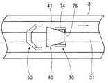
操作部3内には、仕切り板3pが設けられている。仕切り板3pの予め定めた位置には、上下用ノブ軸受16b、左右用ノブ軸受17b、及びレバー軸受18bが固設されている。また、本実施形態において、仕切り板3pには、細長な硬度調整用フレーム3fが固定されている。硬度調整用フレーム3fは、該フレーム3fの長手軸を挿入部延長軸線2aに対して平行にして配置されている。 In the
硬度調整用フレーム3fには、係止部を兼ねる弾性部材70が固定され、ロッド部材30が軸方向に対して進退自在に配設される。
図2、図3に示すように硬度調整用フレーム3fは、長手軸方向に細長な凹み空間3sを備え、底面3bの予め定めた位置に弾性部材70が固定されている。また、凹み空間3sに進退自在に配設されているロッド部材30は、軸本体31に、取付部32、第1凸部40、第2凸部50、及びワイヤー固定部60を設けて構成されている。そして、軸本体31は、弾性部材70の後述する一対の当接部74間に配置されている。
なお、軸本体31の直径は、予め定めた寸法φDである。An
As shown in FIGS. 2 and 3, the
The diameter of the
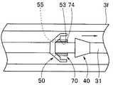
まず、図2−図4を参照して弾性部材70を説明する。
弾性部材70は、予め定めた厚み寸法t、幅寸法w、および長さ寸法の板バネ部材を、予め定めた形状に折り曲げて、断面形状が略凹字形状となるように形作られている。First, the
The
弾性部材70は、固定面71と、一対の弾性変形部72とを備える。一対の弾性変形部72は、固定面71の両側部からそれぞれ立設している。 The
弾性変形部72は、バネ部73及び当接部74を備えている。本実施形態において、当接部74の当接部内面75同士は、例えばバネ部73に負荷が働いていない無負荷状態、言い換えれば、外力によって変形されていない自然状態において、対面するように形成されている。 The
固定面71は、硬度調整用フレーム3fの凹み空間3sの底面3bの予め定めた位置に、接着、半田付け等によって該フレーム3fに一体に固定される。このとき、一対の当接部74は、硬度調整用フレーム3fの長手軸に対して平行に配置される。 The fixing
本実施形態において、一対の当接部74の基端側の面は、位置決め平面76として構成されている。また、一対の当接部内面75間の幅寸法(以下、内幅と略記する)W1は、自然状態においてロッド部材30を構成する軸本体31の外径寸法φDに比べて幅広に設定されている。このため、当接部内面75と軸本体31の外周面との間には、一対の当接部74の内幅W1が狭まるように弾性変形可能にする、予め定めた寸法の隙間が設けられる。
なお、自然状態の当接部74の幅寸法(以下、外幅と略記する)は、W2と記載する。外幅W2は、内幅W1+2×(弾性部材70の厚み寸法t)である。In the present embodiment, the base end surface of the pair of
The width dimension of the
硬度調整用フレーム3fに固定された弾性部材70の一対の当接部74は、ロッド部材30の進退移動に伴って、バネ部73の付勢力に抗して弾性変形する。具体的に、一対の当接部74は、硬度調整用フレーム3fの長手軸に対して直交する方向に対して、内幅W1を拡げつつ弾性変形することが可能であるとともに、内幅W1を狭め(縮め)つつ弾性変形することが可能である。 The pair of
したがって、バネ部73の付勢力に抗して拡げられた当接部74、及びバネ部73の付勢力に抗して狭められた当接部74は、該当接部74にかかる外力の低下等に伴ってバネ部73の付勢力によって再び元の状態に復帰する。 Therefore, the
なお、図4の符号77は、固定ピンである。弾性部材70のフレーム3fに対する一体固定は、上述した接着、半田付け等に限定されるものではなく、固定ピン77を用いて弾性部材70を硬度調整用フレーム3fに固定する構成であってもよい。 In addition, the code |
次に、図2−図5を参照してロッド部材30を説明する。
ロッド部材30は、予め定めた長さ寸法の軸本体31の基端面側から順に、取付部32、第1凸部40、第2凸部50、及びワイヤー固定部60をそれぞれ予め定めた間隔で設けて構成されている。Next, the
The
取付部32は、軸本体31の基端側に一体に設けられる構成、或いは別体に構成されて、ネジ、接着、半田、溶接等によって基端部に一体に固定される構成である。取付部32には、連結部材19の一端が回動自在に取り付けられる。 The
連結部材19は、ロッド部材30と硬度調整用レバー7とを連結されてリンク機構を構成する。連結部材19の一端である先端側には取付部32に回動自在に配置される第1孔19aが形成され、基端側には第2孔19bが形成されている。第2孔19bは、硬度調整用レバー7のレバー先端7fに設けられた凸部7bに回動自在に配置される。 The connecting
この構成によれば、ロッド部材30は、硬度調整用レバー7の回動操作に伴って操作部3の長手軸方向に対して進退移動する。具体的に、ロッド部材30は、硬度調整用レバー7が実線に示す初期位置からレバー用軸18を中心に矢印Y1方向に回転されることによって、第1方向である矢印Y4方向に移動する。一方、ロッド部材30は、硬度調整用レバー7が破線に示す位置からレバー用軸18を中心に破線で示す矢印Y2方向に回転されることによって、第1方向とは逆方向な第2方向である破線で示す矢印Y5方向に移動する。 According to this configuration, the
第1凸部40は、拡径傾斜面41および保持平面42を備え、軸本体31に対して出っ張った略円錐形状に形作られている。第1凸部40は、取付部32の中心から予め定めた距離、離間して設けられている。第1凸部40は、硬度調整用レバー7が初期状態において弾性部材70よりも先端側の凹み空間3s内に配置される。 The first
拡径傾斜面41は、第1凸部40の側周面を構成するテーパー形状の斜面である。拡径傾斜面41は、基端側から先端側にいくにしたがって径寸法がφDからφD1まで連続的に大きくなるように形成されている。 The enlarged diameter
保持平面42は、軸本体41から外周面突出した円環状の平面であり、第1凸部40の先端面を構成する。保持平面42は、弾性部材70の位置決め平面76に対して当接配置される。本実施形態において、保持平面42の幅寸法W3は、安定した保持を可能にする目的で例えば弾性部材70の厚み寸法tを考慮して、その寸法tより予め定めた寸法分大きく設定されている。 The holding
第2凸部50は、軸本体31に対して出っ張り、予め定めた形状に形作られている。第2凸部50は、第1凸部40から予め定めた距離、離間して設けられている。第2凸部50は、一体部51と、対向する一対の突起部52とを備えて主に構成されている。一体部51は、軸本体31に対して一体に形作られている。 The 2nd
一対の突起部52は、一体部51の予め定めた側面からそれぞれ基端側に突出している。一対の突起部52には、それぞれ突起部内側傾斜面である第1傾斜面53と、突起部外側傾斜面である第2傾斜面54とが形成されている。加えて、一対の突起部52にはそれぞれ、軸本体31の長手軸に沿って形成されたスリット55及び案内部56が形成されている。一対の突起部52において、案内部56の案内内面56i同士は、対面するように形成されている。 The pair of
第2凸部50が有する一対の第1傾斜面53は、弾性部材70の当接部74の内幅W1をバネ部73の付勢力に抗して狭める斜面として構成されている。つまり、第1傾斜面53は、一対の第1傾斜面53が構成する突起部52の開口幅を基端側から先端側にいくにしたがって連続的に小さくするように形成されている。そして、本実施形態において、基端側開口幅寸法Wiは、自然状態の当接部74の外幅W2より予め定めた寸法分、大きく設定されている。 The pair of first
第2凸部50が有する一対の第2傾斜面54は、弾性部材70の当接部74の内幅W1をバネ部73の付勢力に抗して拡げる斜面として形成されている。つまり、第2傾斜面54は、一対の第2傾斜面54が構成する突起部52の外形幅を先端側から基端側にいくにしたがって連続的に大きくするように形成されている。そして、基端側外形幅寸法Woは、予め定めた寸法に設定されている。
本実施形態において、第1傾斜面53の傾斜角度と、第2傾斜面54の傾斜角度とは、同じ角度であっても、異なる角度のいずれであってもよい。The pair of second
In the present embodiment, the inclination angle of the first
スリット55は、第1傾斜面53が形成されている当接部弾性変形空間57と、第2傾斜面54が形成されている外部とを連絡する。スリット55は、当接部弾性変形空間57内に配置されている弾性部材70の当接部74を外部に導く導出路である。したがって、スリット55の幅寸法Wsは、弾性部材70の厚み寸法tを考慮して、その寸法tより予め定めた寸法大きく設定されている。 The
案内部56は、第2傾斜面54によって拡げられた弾性部材70の当接部74を付勢力に抗して拡開状態を維持する平面で構成された案内外面56oを有している。
本実施形態において、スリット55と第1傾斜面53とが交差する交差部、スリット55と第2傾斜面54とが交差する交差部、及び第2傾斜面54と案内外面56oとが交差する交差部には、ロッド部材30が進退移動する際に当接部74との引っかかりを防止するための面取りが施してある。The
In the present embodiment, the intersection where the
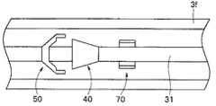
ワイヤー固定部60は、ロッド部材30の最先端を構成する。ワイヤー固定部60は、ロッド部材30の先端部に一体に設けられる構成、或いは別体に構成されて、ネジ、接着、半田、溶接等によってロッド部材30の先端面に一体に固定される構成である。 The
ワイヤー固定部60は、直方体形状であり、硬度調整用ワイヤー22を配置するためのワイヤー用スリット61が形成されている。ワイヤー用スリット61は、各硬度調整用ワイヤー22に対応する位置関係で形成されている。 The
本実施形態において、硬度調整用ワイヤー22の基端にはストッパー24が設けられる。ストッパー24は、硬度調整用ワイヤー22に半田付け、ろう付け等によって一体に固定されている。ストッパー24は、ワイヤー固定部60の基端側面62に当接した状態で該固定部60に配設される。 In the present embodiment, a
なお、図3に示すように本実施形態において、硬度調整用フレーム3fが備える凹み空間3sの幅寸法Wfは、基端側外形幅寸法Woと弾性部材70の厚み寸法tとを考慮して設定される。具体的に、幅寸法Wfは、案内外面56o上に当接部内面75が配置された状態において、凹み空間3sの空間内面3iと当接部74の当接部外面78との間に隙間s1が形成されるように厚み寸法tよりも予め定めた寸法大きく設定されている。 As shown in FIG. 3, in the present embodiment, the width dimension Wf of the recessed
また、図5に示すように本実施形態において、第2凸部50の当接部配置空間58の幅寸法Wmは、保持平面42の径寸法D1と弾性部材70の厚み寸法tとを考慮して設定される。具体的に、幅寸法Wmは、第1凸部40の保持平面42を構成する先端縁部によって当接部74が拡開された状態において、当接部配置空間58の空間内面58iと当接部74の当接部外面78との間に予め定めた隙間s2が形成されるように設定されている。 Further, as shown in FIG. 5, in the present embodiment, the width dimension Wm of the contact
ここで、上述のように構成された硬度調整用レバー7の作用を説明する。
術者は、可撓管部13の硬度を変化させる際、操作部3を把持する手の親指で初期位置に配置されている硬度調整用レバー7を回転操作する。すると、図6に示すように硬度調整用レバー7の矢印Y1方向への回転に伴って、連結部材19が移動するとともにロッド部材30が矢印に示す第1方向に移動して、弛緩状態であった硬度調整用ワイヤー22の牽引が開始される。Here, the action of the hardness adjusting lever 7 configured as described above will be described.
When changing the hardness of the
そして、術者が継続して矢印Y1方向に硬度調整用レバー7を操作し続けることにより、ロッド部材30が第1方向に向かって移動を続ける。この結果、コイルパイプ21は、硬度調整用ワイヤー22の牽引に伴って徐々に圧縮されていく。 Then, when the surgeon continues to operate the hardness adjusting lever 7 in the arrow Y1 direction, the
ロッド部材30が移動することにより、まず、図6に示すように第1凸部40が弾性部材70を構成する当接部74の内幅W1内に配置される。 When the
続いて、図7に示すように第1凸部40の拡径傾斜面41が当接部74に当接する。そして、第1凸部40の移動に伴って当接部74は、図8に示すように拡径傾斜面41によって押し拡げられていく。このとき、押し広げられた当接部74は、第2凸部50の当接部配置空間58内に収容されていく。 Subsequently, as shown in FIG. 7, the enlarged diameter
図9に示すように第1凸部40が弾性部材70を通過すると、押し拡げられていた当接部74は、バネ部73の付勢力によって元の状態に復帰する。 As shown in FIG. 9, when the first
この状態において、術者が硬度調整用レバー7の指当て部7pから手指を離す、すなわち、ロッド部材30の第1方向への移動を停止させると、保持平面42が位置決め平面に76に当接する。この結果、硬度調整用ワイヤー22の牽引状態が保持されるとともに、硬度調整用レバー7は図2の二点鎖線に示す位置で保持状態になる。 In this state, when the surgeon releases his / her finger from the
この保持状態において、硬度調整用ワイヤー22は、予め定めた量、牽引されている。このため、可撓管部13の硬度は、予め定めた硬状態に設定されている。つまり、術者は、保持状態において、硬度調整用レバー7の指当て部7pから指を離して、硬状態に設定された可撓管部13を有する挿入部2の手元操作を行うことができる。 In this holding state, the
なお、当接部74がバネ部73の付勢力によって元の状態に復帰したとき、硬度調整用レバー7を操作する術者の手指には、押し拡げられていた当接部74が元の状態に弾性復帰したことによって発生する振動が伝達される。 When the
このことによって、術者は、ロッド部材30の第1凸部40が弾性部材70を通過したこと、即ち、硬度調整用レバー7から手指を離すことが可能な保持状態に切り替わったことを判断することができる。
つまり、第1凸部40は、術者に硬度調整用レバー7から手指を離すことが可能な保持状態になったことを告知する第1の告知部を兼ねている。Accordingly, the surgeon determines that the first
That is, the 1st
保持状態を解除するとき、術者は、硬度調整用レバー7を再び矢印Y1方向に回転操作する。すると、ロッド部材30は、再び、第1方向に移動を開始する。そして、ロッド部材30の第1方向への移動によって、図10に示すように第2凸部50の一対の第1傾斜面53が当接部74に当接する。このことによって、当接部74は、第2凸部50の第1方向への移動に伴って、第1傾斜面53によって当接部74が押し縮められていく。 When releasing the holding state, the operator rotates the hardness adjusting lever 7 again in the direction of the arrow Y1. Then, the
その後、押し縮められた当接部74は、図11に示すように第1傾斜面53に開口を有するスリット55内に挿入され、引き続きスリット55内を移動されて通過する。すると、図12に示すように押し縮められていた当接部74がバネ部73の付勢力によって元の状態に復帰する。 After that, the pressed
このとき、硬度調整用レバー7を操作する術者の手指には、押し縮められていた当接部74が元の状態に弾性復帰した際に発生する振動が伝達される。このことによって、術者は、ロッド部材30の第2凸部40が弾性部材70を通過したこと、即ち、硬度調整用レバー7が切替位置に到達したことを判断することができる。
つまり、スリット55を有する第2凸部50は、術者に硬度調整用レバー7が切替位置に到達したことを告知する第2の告知部を兼ねている。At this time, vibrations generated when the pressed
That is, the 2nd
ここで、術者は、可撓管部13の硬度を元の状態に復帰させるため、硬度調整用レバー7を矢印Y2方向に回転操作する。すると、ロッド部材30は、図13の矢印に示すように第1方向とは逆方向の第2方向に移動を開始する。このことにより、硬度調整用ワイヤー22の牽引状態が徐々に弛緩状態に変化していく。 Here, the operator rotates the hardness adjusting lever 7 in the direction of the arrow Y2 in order to return the hardness of the
このとき、第2凸部50の第2傾斜面54が、弾性部材70の当接部74に当接しつつ移動していくことにより、当接部74は、図13に示すように押し拡げられていく。そして、ロッド部材30の更なる第2方向への移動によって、図14に示すように案内外面56o上に当接部74の当接部内面75が配置される。そして、案内外面56oが当接部74を通過することによって、押し拡げられていた当接部74がバネ部73の付勢力によって元の状態に復帰する。このとき、図15に示すように当接部74の内幅W1内に第1凸部40が配置されているため、当接部74は、復帰途中で拡径傾斜面41面上に配置された状態になる。 At this time, the second
この後、術者が、硬度調整用レバー7を矢印Y2方向に引き続き回転させることにより、ロッド部材30は、第2方向に移動されていく。そして、硬度調整用レバー7が初期位置に復帰することによって、図16に示すようにロッド部材30も元の位置に配置される。すなわち、硬度調整用ワイヤー22が再び弛緩状態になって、可撓管部13の硬度が元の硬さに復帰する。 Thereafter, when the surgeon continues to rotate the hardness adjusting lever 7 in the direction of the arrow Y2, the
このように、硬度調整用フレーム3fの予め定めた位置にバネ部73と位置決め面76を備える当接部74とを有する弾性部材70を固設する一方、拡径傾斜面41と保持平面42とを有する第1凸部40を軸本体31に一体に設けたロッド部材30を硬度調整用フレーム3fに配置する。その際、軸本体31を弾性部材70の一対の当接部74の間に配置して、第1凸部40を弾性部材70に対して予め定めた方向に離間して配置する。また、硬度調整用レバー7の回動操作に伴ってロッド部材30が第1方向及びその逆方向である第2方向に進退移動するように構成する。この結果、第1方向に移動されるロッド部材30に設けられた第1凸部40が弾性部材70を通過した後、保持平面42が当接部74の位置決め面76に当接することによって、ロッド部材30の第1方向の移動位置を保持する保持状態を得ることができる。 As described above, the
また、軸本体31に第1凸部40に加えて、第1傾斜面53、第2傾斜面54、及びスリット55を設けた第2凸部50を、第1凸部40から予め定めた方向に予め定めた距離、離間させて設けておく。この結果、保持状態において、ロッド部材30を再び第1方向に移動させることによって、当接部74を第2凸部50の当接部弾性変形空間57内からスリット55を介して第2凸部50の外部に導出させ、その後、ロッド部材30が第2方向に移動するように硬度調整用レバー7を回動操作することにより、保持状態の解除を行うことができる。 In addition to the first
さらに、硬度調整用レバー7を上下用ノブ6a及び左右用ノブ6bと同軸に配置すると共に、硬度調整用レバー7の回動範囲を既定して、その初期位置における硬度調整用レバー7の指当て部7pの位置を、操作部3を把持する術者の手の親指で操作可能な位置に設定している。この結果、術者は、操作部3を把持する手の親指で、上下用ノブ6a、左右用ノブ6b及び硬度調整用レバー7の操作を行える。つまり、術者は、挿入部を把持している手を離すことなく、簡単な操作でワイヤーの牽引、保持、解除を行うことができる。 Further, the hardness adjusting lever 7 is disposed coaxially with the up / down
なお、上述した実施形態においては、挿入部2に第1機能部である湾曲部12の他に第2機能部として硬度可変機構を設けている。しかし、第2機能部は、硬度可変機構に限定されるものではなく、言い換えれば、第2牽引部材は硬度調整用ワイヤー22に限定されるものではなく、第2牽引操作装置も硬度調整用レバー7に限定されるものではない。 In the above-described embodiment, the
即ち、第2牽引部材及び第2牽引操作装置は、例えば、内視鏡の湾曲部の硬度を部分的に可変させて湾曲部の湾曲半径を可変させる湾曲形状可変用ワイヤー及湾曲形状切替装置、或いは、挿入部の先端部内に設けられた撮像ユニットに進退自在に設けた移動レンズ枠を広角位置、中間倍率位置、拡大位置等に進退させる移動レンズ枠操作用ワイヤー及移動レンズ枠操作装置、或いは、処置具チャンネルを介して挿入部の先端部から体内等に導出される例えば鉗子の導出向きを調整する鉗子起上台を起上降下させる鉗子起上用ワイヤー及鉗子起上操作装置、等であってもよい。 That is, the second traction member and the second traction operation device include, for example, a bending shape changing wire and a bending shape switching device that change the bending radius of the bending portion by partially changing the hardness of the bending portion of the endoscope, Alternatively, a moving lens frame operating wire and a moving lens frame operating device for moving the moving lens frame provided in the imaging unit provided in the distal end portion of the insertion portion so as to freely move back and forth to a wide angle position, an intermediate magnification position, an enlarged position, etc., or A forceps raising wire and a forceps raising operation device for raising and lowering a forceps raising base that adjusts the leading direction of the forceps led out from the distal end portion of the insertion portion to the body or the like through the treatment instrument channel. May be.
また、上述した実施形態においては、弾性部材70の当接部内面75同士が、自然状態において、対面するように形成している。しかし、弾性部材70の当接部内面75同士が、案内外面56o上に配置されている状態において対面する、或いはスリット55内を通過している状態において対面する等のように形成するようにしてもよい。 Moreover, in embodiment mentioned above, it forms so that the contact part
また、上述した実施形態おいては、軸本体31の径寸法を当接部内面75と軸本体31の外周面との間に予め定めた寸法の隙間が設けられるようにφDに設定している。しかし、第1凸部40と第2凸部50との間の軸本体の径寸法だけをφDに設定するようにしてもよい。 In the embodiment described above, the diameter dimension of the
また、上述した実施形態においては、軸本体31に取付部32、第1凸部40、第2凸部50及びワイヤー固定部60を一体に設けてロッド部材30を構成する、或いは、第1凸部40及び第2凸部50を一体に設けた軸本体31に取付部32及びワイヤー固定部60を固設してロッド部材30を構成するとしている。しかし、ロッド部材30の構成は、上述した構成に限定されるものではなく、例えば、図17及び図18に示すように第2凸部50を軸本体31に取付可能なロッド部材30Aを構成にするようにしてもよい。 In the above-described embodiment, the
図17に示すようにロッド部材30Aは、第1凸部40を一体に設けた第1軸体31Aと、第2凸部50を構成する凸部本体80と、凸部本体80を第1軸体31Aと共に挟持固定する第2軸体31Bとを備えて構成されている。即ち、本実施形態において、軸本体31は、第1軸体31Aと、第2軸体31Bとで構成される。 As shown in FIG. 17, the
第1軸体31Aは、保持平面42から予め定めた量突出する円柱突起43を有している。円柱突起43の先端面には雌ネジ部44が設けられている。一方、第2軸体31Bは、端部に押圧面45を備え、押圧面45から予め定めた量突出する雄ネジ部46を有している。雄ネジ部46は、雌ネジ部44に螺合可能である。
そして、第1軸体31Aの図示されない端部には取付部32が固設可能であり、第2軸体31Bの図示されない端部には60がワイヤー固定部が固設可能である。The
An
凸部本体80は、取付面部81と、前記突起部52と同様な構成及び機能を有する一対の突起部82とを備えている。取付面部81には、雄ネジ部46が挿通可能な貫通孔81aが形成されている。そして、第1軸体31Aの図示されない端部には取付部32が固設可能であり、第2軸体31Bの図示されない端部には60がワイヤー固定部が固設可能である。 The
一対の突起部82は、取付面部81から基端側に突出し、突起部内側傾斜面である第1傾斜面83と、突起部外側傾斜面である第2傾斜面84とが形成されている。加えて、一対の突起部82にはそれぞれスリット85及び案内部86が形成されている。 The pair of projecting
そして、図17に示すように第1軸体31A、凸部本体80及び第2軸体31Bを配置し、雄ネジ部46を貫通孔81aを介して雌ネジ部44に螺合する。このことによって、取付面部81が保持平面42と押圧面45とによって押圧挟持されて、図18に示すロッド部材30Aが構成される。そして、ロッド部材30Aの凸部本体80は、第2凸部50として機能する。 Then, as shown in FIG. 17, the
この構成によれば、凸部本体80の交換を容易に行える。また、第1軸体31Aにおいて、円柱突起43の直径を第1軸体31Aの直径より小さく設定することによって、第1傾斜面83によって縮められる当接部74の外幅の変形量を大きくすることができる。 According to this configuration, the
尚、本発明は、以上述べた実施形態のみに限定されるものではなく、発明の要旨を逸脱しない範囲で種々変形実施可能である。 The present invention is not limited to the above-described embodiments, and various modifications can be made without departing from the spirit of the invention.
1…内視鏡 2…挿入部 2a…挿入部延長軸線 3…操作部 3b…底面
3f…硬度調整用フレーム 3i…空間内面 3p…仕切り板 3s…凹み空間
4…ユニバーサルコード 5…コネクター 6…湾曲部操作ノブ 6a…上下用ノブ
6b…左右用ノブ 7…硬度調整用レバー 7b…凸部 7f…レバー先端
7p…指当て部 7r…レバー基端 11…先端部 12…湾曲部 13…可撓管部
14…湾曲駒 14f…先端湾曲駒 15D…下用湾曲ワイヤー
15L…左用湾曲ワイヤー 15R…右用湾曲ワイヤー 15U…上用湾曲ワイヤー
16…上下用ノブ軸 16b…上下用ノブ軸受 17…左右用ノブ軸
17b…左右用ノブ軸受 18…レバー用軸 18b…レバー軸受 18c…回動中心
19…連結部材 19a…第1孔 19b…第2孔 21…コイルパイプ
22…硬度調整用ワイヤー 23…接続管 24…ストッパー 30…ロッド部材
30A…ロッド部材 31…軸本体 31A…第1軸体 31B…第2軸体
32…取付部 40…第1凸部 41…拡径傾斜面 42…保持平面 43…円柱突起
44…雌ネジ部 45…押圧面 46…雄ネジ部 50…第2凸部 51…一体部
52…突起部 53…第1傾斜面 54…第2傾斜面 55…スリット 56…案内部
56i…案内内面 56o…案内外面 57…当接部弾性変形空間
58…当接部配置空間 58i…空間内面 60…ワイヤー固定部
61…ワイヤー用スリット 62…基端側面 70…弾性部材 71…固定面
72…弾性変形部 73…バネ部 74…当接部 75…当接部内面
76…位置決め平面 77…固定ピン 78…当接部外面 80…凸部本体
81…取付面部 81a…貫通孔 82…突起部 83…第1傾斜面 84…第2傾斜面
85…スリット 86…案内部DESCRIPTION OF
3f ... Hardness adjusting frame 3i ... Space
DESCRIPTION OF SYMBOLS 4 ... Universal cord 5 ...
15L ...
17b ... Left knob bearing 18 ... Lever shaft 18b ... Lever bearing 18c ...
DESCRIPTION OF
32 ... Mounting
44 ...
52 ... Protruding
58 ... Space for contact portion arrangement 58i ... Space
61 ... Wire slit 62 ... Base
72 ...
76 ... Positioning
Claims (6)
Translated fromJapanese前記湾曲部を湾曲させる第1牽引部材の基端が固定され、回動することで該第1牽引部材を牽引あるいは弛緩する第1牽引操作装置、及び回動自在に設けられ前記第1牽引部材とは異なる第2牽引部材を牽引する際に操作される第2牽引操作装置を備える、前記挿入部の基端側に設けられた把持部を兼ねる操作部と、
前記操作部内に進退自在に配置され、前記第2牽引操作装置を初期位置から一方向に回転させることによって操作部長手軸の第1方向に移動し、該第2牽引操作装置を初期位置に戻すように他方向に回転させることによって前記第1方向とは逆方向である第2方向に移動する、前記第2牽引部材の基端が固定されるロッド部材と、
前記操作部内の予め定めた位置に固設され、前記ロッド部材の第1方向への移動及び第2方向への移動によって、該操作部長手軸方向に対して直交する拡がる方向、及び縮まる方向に弾性変形可能で前記ロッド部材の前記操作部長手軸方向の位置を保持するための位置決め面を有する一対の当接部を有する弾性部材と、を備え、
前記ロッド部材は、軸本体と、該軸本体に基端側から順に固設される、
前記ロッド部材の基端面側に設けられ、前記ロッド部材と前記第2牽引操作装置とを連結する連結部材が取りつけられる取付部と、
前記取付部より前記ロッド部材の先端側に設けられ、該ロッド部材の第1方向への移動に伴って前記一対の当接部を徐々に拡げる拡径傾斜面および前記弾性部材の位置決め面に当接する保持平面を備える第1凸部と、
前記第1凸部より前記ロッド部材の先端側に設けられ、該ロッド部材の第1方向への移動に伴って前記一対の当接部の間隔を徐々に縮める一対の第1傾斜面、前記ロッド部材の更なる第1方向への移動に伴って前記第1傾斜面によって縮められた前記一対の当接部が通過可能なスリット、および当該ロッド部材の第2方向への移動に伴って前記一対の当接部を徐々に拡げる一対の第2傾斜面を備える第2凸部と、
前記ロッド部材の先端面側に設けられ、前記第2牽引部材の基端が固定されるワイヤー固定部と、を
具備することを特徴とする内視鏡。In order from the distal end side, an insertion portion configured by connecting a distal end portion, a bending portion, and a flexible tube portion, and
The first traction member for bending or bending the first traction member that bends the bending portion is fixed and rotated, and the first traction member is provided rotatably. An operation portion that also serves as a gripping portion provided on a proximal end side of the insertion portion, and includes a second pulling operation device that is operated when pulling a second pulling member that is different from
The second traction operation device is disposed in the operation portion so as to freely advance and retreat, and moves in the first direction of the longitudinal axis of the operation portion by rotating the second traction operation device in one direction from the initial position, thereby returning the second traction operation device to the initial position. A rod member to which a proximal end of the second traction member is fixed, which moves in a second direction that is opposite to the first direction by rotating in the other direction,
Fixed to a predetermined position in the operation portion, and in a direction of expansion perpendicular to the operation portion longitudinal axis direction and a direction of contraction by movement of the rod member in the first direction and movement in the second direction. An elastic member having a pair of contact portions that are elastically deformable and have a positioning surface for holding the position of the rod member in the longitudinal direction of the operation portion;
The rod member is fixed to the shaft main body and the shaft main body in order from the base end side.
An attachment portion provided on a base end surface side of the rod member, to which a connecting member for connecting the rod member and the second traction operation device is attached;
It is provided on the distal end side of the rod member from the mounting portion, and contacts the enlarged diameter inclined surface that gradually expands the pair of contact portions as the rod member moves in the first direction and the positioning surface of the elastic member. A first convex portion having a holding plane in contact therewith;
A pair of first inclined surfaces that are provided on the distal end side of the rod member from the first convex portion and gradually reduce the distance between the pair of contact portions as the rod member moves in the first direction, the rod A slit through which the pair of contact portions contracted by the first inclined surface as the member further moves in the first direction can pass, and the pair as the rod member moves in the second direction. A second convex portion having a pair of second inclined surfaces that gradually expand the abutting portion;
An endoscope comprising: a wire fixing portion provided on a distal end surface side of the rod member and to which a proximal end of the second pulling member is fixed.
初期位置から一方向に回転させることによって前記ロッド部材を第1方向に移動させて第2牽引部材を牽引し、
前記ロッド部材の第1方向への移動によって該ロッド部材に固設された前記第1凸部が前記弾性部材を通過することによって、前記第2牽引部材の牽引状態を保持し、
前記第2牽引部材を保持している状態から、前記牽引操作装置をさらに一方向に回転させて切替位置まで移動させることによって保持状態を解除し、
前記第2牽引装置を、前記切替位置から他方向に回転させることによって、前記ロッド部材を第2方向に移動させて、前記第2牽引部材を弛緩させていく、
ことを特徴とする請求項1に記載の内視鏡。The second traction operation device includes:
The rod member is moved in the first direction by rotating in one direction from the initial position, and the second pulling member is pulled,
When the first convex portion fixed to the rod member passes through the elastic member by the movement of the rod member in the first direction, the traction state of the second traction member is maintained,
From the state where the second traction member is held, the traction operation device is further rotated in one direction and moved to the switching position to release the holding state,
The rod member is moved in the second direction by rotating the second traction device in the other direction from the switching position, and the second traction member is relaxed.
The endoscope according to claim 1.
Priority Applications (1)
| Application Number | Priority Date | Filing Date | Title |
|---|---|---|---|
| JP2011171185AJP5669690B2 (en) | 2011-08-04 | 2011-08-04 | Endoscope |
Applications Claiming Priority (1)
| Application Number | Priority Date | Filing Date | Title |
|---|---|---|---|
| JP2011171185AJP5669690B2 (en) | 2011-08-04 | 2011-08-04 | Endoscope |
Publications (2)
| Publication Number | Publication Date |
|---|---|
| JP2013034547Atrue JP2013034547A (en) | 2013-02-21 |
| JP5669690B2 JP5669690B2 (en) | 2015-02-12 |
Family
ID=47884771
Family Applications (1)
| Application Number | Title | Priority Date | Filing Date |
|---|---|---|---|
| JP2011171185AExpired - Fee RelatedJP5669690B2 (en) | 2011-08-04 | 2011-08-04 | Endoscope |
Country Status (1)
| Country | Link |
|---|---|
| JP (1) | JP5669690B2 (en) |
Cited By (6)
| Publication number | Priority date | Publication date | Assignee | Title |
|---|---|---|---|---|
| JP2018117925A (en)* | 2017-01-26 | 2018-08-02 | オリンパス株式会社 | Endoscope |
| JP6402285B1 (en)* | 2017-05-10 | 2018-10-10 | オリンパス株式会社 | Endoscope |
| WO2018207514A1 (en)* | 2017-05-10 | 2018-11-15 | オリンパス株式会社 | Endoscope |
| JPWO2022071564A1 (en)* | 2020-10-02 | 2022-04-07 | ||
| CN119055167A (en)* | 2024-11-05 | 2024-12-03 | 湖南省华芯医疗器械有限公司 | Endoscope thumbwheel assembly, endoscope handle and endoscope |
| CN120000133A (en)* | 2025-03-26 | 2025-05-16 | 江苏省肿瘤医院 | Endoscopic insertion aid and endoscopy device |
Citations (13)
| Publication number | Priority date | Publication date | Assignee | Title |
|---|---|---|---|---|
| JPH0343802U (en)* | 1989-09-07 | 1991-04-24 | ||
| JPH09108176A (en)* | 1995-10-20 | 1997-04-28 | Olympus Optical Co Ltd | Endoscope |
| JPH09294710A (en)* | 1996-05-07 | 1997-11-18 | Olympus Optical Co Ltd | Endoscope |
| JPH1014860A (en)* | 1996-06-28 | 1998-01-20 | Olympus Optical Co Ltd | Endoscope |
| JP2987452B2 (en)* | 1990-05-17 | 1999-12-06 | オリンパス光学工業株式会社 | Endoscope |
| JP2002291685A (en)* | 2001-03-29 | 2002-10-08 | Fuji Photo Optical Co Ltd | Endoscope |
| JP2002325723A (en)* | 2001-05-01 | 2002-11-12 | Asahi Optical Co Ltd | Endoscope device |
| JP2003000533A (en)* | 2001-06-25 | 2003-01-07 | Olympus Optical Co Ltd | Endoscopic apparatus |
| JP2003225197A (en)* | 2002-02-05 | 2003-08-12 | Pentax Corp | Flexible endoscope |
| JP2006512935A (en)* | 2002-06-13 | 2006-04-20 | ユーエスジーアイ メディカル, インコーポレイテッド | A method of advancing an instrument through a shape-fixable device and an unsupported anatomical structure. |
| US20070282167A1 (en)* | 2006-05-19 | 2007-12-06 | Michael Barenboym | Control mechanism for steerable medical device |
| JP4254275B2 (en)* | 2003-03-03 | 2009-04-15 | フジノン株式会社 | Endoscope |
| JP4676427B2 (en)* | 2003-04-01 | 2011-04-27 | ボストン サイエンティフィック リミテッド | Disposable endoscopic imaging system |
- 2011
- 2011-08-04JPJP2011171185Apatent/JP5669690B2/ennot_activeExpired - Fee Related
Patent Citations (13)
| Publication number | Priority date | Publication date | Assignee | Title |
|---|---|---|---|---|
| JPH0343802U (en)* | 1989-09-07 | 1991-04-24 | ||
| JP2987452B2 (en)* | 1990-05-17 | 1999-12-06 | オリンパス光学工業株式会社 | Endoscope |
| JPH09108176A (en)* | 1995-10-20 | 1997-04-28 | Olympus Optical Co Ltd | Endoscope |
| JPH09294710A (en)* | 1996-05-07 | 1997-11-18 | Olympus Optical Co Ltd | Endoscope |
| JPH1014860A (en)* | 1996-06-28 | 1998-01-20 | Olympus Optical Co Ltd | Endoscope |
| JP2002291685A (en)* | 2001-03-29 | 2002-10-08 | Fuji Photo Optical Co Ltd | Endoscope |
| JP2002325723A (en)* | 2001-05-01 | 2002-11-12 | Asahi Optical Co Ltd | Endoscope device |
| JP2003000533A (en)* | 2001-06-25 | 2003-01-07 | Olympus Optical Co Ltd | Endoscopic apparatus |
| JP2003225197A (en)* | 2002-02-05 | 2003-08-12 | Pentax Corp | Flexible endoscope |
| JP2006512935A (en)* | 2002-06-13 | 2006-04-20 | ユーエスジーアイ メディカル, インコーポレイテッド | A method of advancing an instrument through a shape-fixable device and an unsupported anatomical structure. |
| JP4254275B2 (en)* | 2003-03-03 | 2009-04-15 | フジノン株式会社 | Endoscope |
| JP4676427B2 (en)* | 2003-04-01 | 2011-04-27 | ボストン サイエンティフィック リミテッド | Disposable endoscopic imaging system |
| US20070282167A1 (en)* | 2006-05-19 | 2007-12-06 | Michael Barenboym | Control mechanism for steerable medical device |
Cited By (8)
| Publication number | Priority date | Publication date | Assignee | Title |
|---|---|---|---|---|
| JP2018117925A (en)* | 2017-01-26 | 2018-08-02 | オリンパス株式会社 | Endoscope |
| JP6402285B1 (en)* | 2017-05-10 | 2018-10-10 | オリンパス株式会社 | Endoscope |
| WO2018207514A1 (en)* | 2017-05-10 | 2018-11-15 | オリンパス株式会社 | Endoscope |
| JPWO2022071564A1 (en)* | 2020-10-02 | 2022-04-07 | ||
| WO2022071564A1 (en)* | 2020-10-02 | 2022-04-07 | 富士フイルム株式会社 | Endoscope |
| CN119055167A (en)* | 2024-11-05 | 2024-12-03 | 湖南省华芯医疗器械有限公司 | Endoscope thumbwheel assembly, endoscope handle and endoscope |
| CN119055167B (en)* | 2024-11-05 | 2025-03-04 | 湖南省华芯医疗器械有限公司 | Thumb wheel assembly of endoscope, endoscope handle and endoscope |
| CN120000133A (en)* | 2025-03-26 | 2025-05-16 | 江苏省肿瘤医院 | Endoscopic insertion aid and endoscopy device |
Also Published As
| Publication number | Publication date |
|---|---|
| JP5669690B2 (en) | 2015-02-12 |
Similar Documents
| Publication | Publication Date | Title |
|---|---|---|
| JP5669690B2 (en) | Endoscope | |
| US8133171B2 (en) | Wire spring guide for flexible endoscope | |
| US9172227B2 (en) | Wire guide member | |
| JP5851118B2 (en) | Endoscope device | |
| CN102711584B (en) | Endoscope | |
| US9814373B2 (en) | Passive bending section for endoscope, and endoscope | |
| US9468359B2 (en) | Control apparatus | |
| JP5784855B2 (en) | Endoscope | |
| JPWO2010089923A1 (en) | Medical tube | |
| JP2015042234A (en) | Medical manipulator | |
| JP2010194102A (en) | Separable endoscope and operating part of separable endoscope | |
| JP6503520B2 (en) | Endoscope | |
| CN108601600B (en) | endoscopy tool | |
| US20170150879A1 (en) | Bendable tube segment, bendable tube and insertion device | |
| JP5942050B2 (en) | Endoscope | |
| US10506919B2 (en) | Operation switching mechanism and endoscope | |
| US9931024B2 (en) | Endoscope | |
| JP4355022B2 (en) | Flexible endoscope | |
| JP7308084B2 (en) | multi-DOF forceps | |
| WO2019003613A1 (en) | Endoscope device, endoscope system, light projection device, and fluid treatment device | |
| JP2011072413A (en) | Guide tube, and endoscope apparatus equipped with the same | |
| CN114532967A (en) | Arthroscope lens with adjustable lens angle | |
| JP2006510463A (en) | Flexible endoscope | |
| JP6839548B2 (en) | Endoscope | |
| JP2023133416A (en) | Tube part for insertion body |
Legal Events
| Date | Code | Title | Description |
|---|---|---|---|
| A621 | Written request for application examination | Free format text:JAPANESE INTERMEDIATE CODE: A621 Effective date:20131004 | |
| A977 | Report on retrieval | Free format text:JAPANESE INTERMEDIATE CODE: A971007 Effective date:20140314 | |
| A131 | Notification of reasons for refusal | Free format text:JAPANESE INTERMEDIATE CODE: A131 Effective date:20140415 | |
| A521 | Request for written amendment filed | Free format text:JAPANESE INTERMEDIATE CODE: A523 Effective date:20140609 | |
| TRDD | Decision of grant or rejection written | ||
| A01 | Written decision to grant a patent or to grant a registration (utility model) | Free format text:JAPANESE INTERMEDIATE CODE: A01 Effective date:20141202 | |
| A61 | First payment of annual fees (during grant procedure) | Free format text:JAPANESE INTERMEDIATE CODE: A61 Effective date:20141216 | |
| R151 | Written notification of patent or utility model registration | Ref document number:5669690 Country of ref document:JP Free format text:JAPANESE INTERMEDIATE CODE: R151 | |
| S111 | Request for change of ownership or part of ownership | Free format text:JAPANESE INTERMEDIATE CODE: R313111 | |
| R350 | Written notification of registration of transfer | Free format text:JAPANESE INTERMEDIATE CODE: R350 | |
| S531 | Written request for registration of change of domicile | Free format text:JAPANESE INTERMEDIATE CODE: R313531 | |
| R350 | Written notification of registration of transfer | Free format text:JAPANESE INTERMEDIATE CODE: R350 | |
| R250 | Receipt of annual fees | Free format text:JAPANESE INTERMEDIATE CODE: R250 | |
| R250 | Receipt of annual fees | Free format text:JAPANESE INTERMEDIATE CODE: R250 | |
| R250 | Receipt of annual fees | Free format text:JAPANESE INTERMEDIATE CODE: R250 | |
| R250 | Receipt of annual fees | Free format text:JAPANESE INTERMEDIATE CODE: R250 | |
| R250 | Receipt of annual fees | Free format text:JAPANESE INTERMEDIATE CODE: R250 | |
| R250 | Receipt of annual fees | Free format text:JAPANESE INTERMEDIATE CODE: R250 | |
| LAPS | Cancellation because of no payment of annual fees |