JP2013033306A - Data division device, data division method and data division program - Google Patents
Data division device, data division method and data division programDownload PDFInfo
- Publication number
- JP2013033306A JP2013033306AJP2011167784AJP2011167784AJP2013033306AJP 2013033306 AJP2013033306 AJP 2013033306AJP 2011167784 AJP2011167784 AJP 2011167784AJP 2011167784 AJP2011167784 AJP 2011167784AJP 2013033306 AJP2013033306 AJP 2013033306A
- Authority
- JP
- Japan
- Prior art keywords
- data
- bucket
- information
- group
- stored
- Prior art date
- Legal status (The legal status is an assumption and is not a legal conclusion. Google has not performed a legal analysis and makes no representation as to the accuracy of the status listed.)
- Granted
Links
Images


Classifications
- G—PHYSICS
- G06—COMPUTING OR CALCULATING; COUNTING
- G06F—ELECTRIC DIGITAL DATA PROCESSING
- G06F16/00—Information retrieval; Database structures therefor; File system structures therefor
- G06F16/10—File systems; File servers
- G—PHYSICS
- G06—COMPUTING OR CALCULATING; COUNTING
- G06F—ELECTRIC DIGITAL DATA PROCESSING
- G06F16/00—Information retrieval; Database structures therefor; File system structures therefor
- G06F16/20—Information retrieval; Database structures therefor; File system structures therefor of structured data, e.g. relational data
- G06F16/24—Querying
- G06F16/245—Query processing
- G06F16/2455—Query execution
- G06F16/24568—Data stream processing; Continuous queries
- G—PHYSICS
- G06—COMPUTING OR CALCULATING; COUNTING
- G06F—ELECTRIC DIGITAL DATA PROCESSING
- G06F16/00—Information retrieval; Database structures therefor; File system structures therefor
- G06F16/20—Information retrieval; Database structures therefor; File system structures therefor of structured data, e.g. relational data
Landscapes
- Engineering & Computer Science (AREA)
- Theoretical Computer Science (AREA)
- Data Mining & Analysis (AREA)
- Databases & Information Systems (AREA)
- Physics & Mathematics (AREA)
- General Engineering & Computer Science (AREA)
- General Physics & Mathematics (AREA)
- Computational Linguistics (AREA)
- Information Retrieval, Db Structures And Fs Structures Therefor (AREA)
Abstract
Description
Translated fromJapanese本発明は、データ分割装置、データ分割方法およびデータ分割プログラムに関する。 The present invention relates to a data dividing device, a data dividing method, and a data dividing program.
近年、ネットワーク技術やセンサー技術の発達と普及に伴い、時々刻々と大量に発生するストリームデータを、リアルタイムに処理することを目的としたストリーム処理が注目されている。 In recent years, with the development and popularization of network technology and sensor technology, attention has been focused on stream processing for the purpose of processing stream data generated in large quantities every moment in real time.
ストリーム処理の利用例を挙げると、ストリームデータとしてPOS(Point of sale system)データを受信し、受信したPOSデータを複数のグループに分割して、即時的な売り上げを集計することに利用されている。また、ストリームデータとしてプローブ交通情報を受信して、受信したプローブ交通情報を複数のグループに分割して、即時的な交通量を集計することに利用されている。 As an example of the use of stream processing, POS (Point of sale system) data is received as stream data, and the received POS data is divided into a plurality of groups and used for totalizing immediate sales. . Also, it is used to receive probe traffic information as stream data, divide the received probe traffic information into a plurality of groups, and total the instantaneous traffic volume.
このようなストリーム処理としては、ストリームデータをレコードとして蓄積し、ユーザから指示があった場合に、蓄積されるレコードを分割する技術が知られている。一例を挙げると、連番などのレコードを特定する項目を持たないストリームデータを、ストリームデータ中の特定の項目でソートしながら蓄積する。なお、連番とは、例えばデータに対して上からまたは下から順番に割り当てる番号などである。そして、ユーザから分割要求を受け付けた場合に、ソートされて蓄積されるレコードを分割してユーザに出力する。 As such stream processing, a technique is known in which stream data is stored as a record and the stored record is divided when an instruction is received from a user. As an example, stream data that does not have an item for specifying a record such as a serial number is accumulated while being sorted by a specific item in the stream data. The serial number is, for example, a number assigned to data in order from the top or bottom. And when the division | segmentation request | requirement is received from a user, the record sorted and accumulate | stored is divided | segmented and output to a user.
しかしながら、従来技術では、連番などレコードを特定する項目が含まれないストリームデータをグループ分けするには時間がかかるという問題がある。 However, the conventional technique has a problem that it takes time to group stream data that does not include items for specifying records such as serial numbers.
例えば、蓄積後にソートされたストリームデータをグループ分けする場合に、全体のデータ件数に対してどのレコードが分割位置になるかを特定する。そして、分割位置として特定されたレコードまで蓄積されたレコードを逐次読み込み、読み込んだレコードまでを1グループとして分割することになる。したがって、複数のグループに分割する場合には、1つのグループごとに、分割位置の特定、レコード読み込み、グループ化を繰り返すことになるので、全レコードを複数のグループを分けるのに時間がかかる。 For example, when stream data sorted after accumulation is grouped, it is specified which record is a division position with respect to the total number of data items. The records accumulated up to the record specified as the division position are sequentially read, and the read records are divided into one group. Therefore, when dividing into a plurality of groups, the identification of the dividing position, the record reading, and the grouping are repeated for each group, so it takes time to divide all the records into a plurality of groups.
なお、蓄積してソートされた後に、ストリームデータ各々に連番を与えることも考えられるが、ストリームデータを受信するたびにソートを実行して、ソート後に新たに連番を毎回与える処理を実行することは、処理負荷が大きく現実的ではない。 Although it is conceivable that serial numbers are assigned to each stream data after being accumulated and sorted, sorting is performed every time stream data is received, and processing for newly assigning serial numbers after sorting is performed. This is unrealistic because of the heavy processing load.
開示の技術は、上記に鑑みてなされたものであって、連番を持たせることなくグループ分けにかかる時間を短縮できるデータ分割装置、データ分割方法およびデータ分割プログラムを提供することを目的とする。 The disclosed technology has been made in view of the above, and an object thereof is to provide a data dividing device, a data dividing method, and a data dividing program capable of reducing the time required for grouping without giving a serial number. .
本願の開示するデータ分割装置、データ分割方法およびデータ分割プログラムは、一つの態様において、前後のデータを特定する前後情報を対応付けた複数のデータを記憶するデータ記憶部を有する。また、前記データ記憶部に記憶されるデータが予め定めたグループ数に分割されるグループごとに、当該グループ内の先頭に位置するデータを特定する先頭情報と当該グループ内の末尾に位置するデータを特定する末尾情報とを記憶する情報記憶部を有する。また、前記データ記憶部にデータを格納する場合に、当該データが有する項目に基づいて当該データの前後となるデータを特定し、当該前後のデータを特定する前後情報を対応付けて前記データ記憶部に格納する格納制御部を有する。また、前記格納制御部によってデータが挿入された場合に、前記各グループに属するデータ数の差が1つ以下となるように、前記情報記憶部に記憶される前記グループごとの先頭情報と末尾情報とを更新する更新部を有する。 In one aspect, a data division device, a data division method, and a data division program disclosed in the present application include a data storage unit that stores a plurality of pieces of data associated with front and rear information for specifying preceding and following data. In addition, for each group in which data stored in the data storage unit is divided into a predetermined number of groups, head information for specifying data located at the head in the group and data located at the end in the group An information storage unit that stores tail information to be specified is included. In addition, when storing data in the data storage unit, the data storage unit identifies data before and after the data based on an item of the data, and associates the before and after information specifying the data before and after the data And a storage control unit for storing in the storage. In addition, when data is inserted by the storage control unit, the start information and end information for each group stored in the information storage unit so that the difference in the number of data belonging to each group is 1 or less. And an update unit for updating the.
本願の開示するデータ分割装置、データ分割方法およびデータ分割プログラムの一つの態様によれば、連番を持たせることなくグループ分けにかかる時間を短縮できるという効果を奏する。 According to one aspect of the data dividing device, the data dividing method, and the data dividing program disclosed in the present application, there is an effect that the time required for grouping can be shortened without giving a serial number.
以下に、本願の開示するデータ分割装置、データ分割方法およびデータ分割プログラムの実施例を図面に基づいて詳細に説明する。なお、この実施例によりこの発明が限定されるものではない。 Hereinafter, embodiments of a data division apparatus, a data division method, and a data division program disclosed in the present application will be described in detail with reference to the drawings. Note that the present invention is not limited to the embodiments.
実施例1では、データ分割装置を含むシステムの全体構成例、データ分割装置の構成を示す機能ブロック図、処理の流れ等について説明する。 In the first embodiment, an overall configuration example of a system including a data dividing device, a functional block diagram showing the configuration of the data dividing device, a processing flow, and the like will be described.
[全体構成]
図1は、実施例1に係るシステムの全体構成例を示す図である。図1に示すように、このシステムは、ストリームデータ発生装置1とデータ分割装置10とユーザ端末5とを有する。ストリームデータ発生装置1とデータ分割装置10とはネットワークを介して接続され、同様に、ユーザ端末5とデータ分割装置10とはネットワークを介して接続される。[overall structure]
FIG. 1 is a diagram illustrating an example of the overall configuration of a system according to the first embodiment. As shown in FIG. 1, this system includes a stream
ストリームデータ発生装置1は、ストリームデータを発生させた順番でデータ分割装置10に送信する装置である。例えば、ストリームデータ発生装置1は、POSデータやプローブ交通情報をストリームデータとしてデータ分割装置10に送信する。なお、実施例1では、ストリームデータとしてPOSデータを用いた例で説明する。 The stream
ユーザ端末5は、ストリームデータ発生装置1が発生させるストリームデータを管理したり、解析したりするユーザが利用する装置である。このユーザ端末5は、データ分割装置10から所望のストリームデータを取得する。ユーザは、ユーザ端末5を用いて取得したストリームデータを解析して、即時的な売り上げを集計したり、即時的な交通量を集計したりする。 The
データ分割装置10は、ストリームデータ発生装置1からストリームデータを受信し、前後のデータを特定する前後情報を対応付けた複数のデータを記憶する。そして、データ分割装置10は、記憶されるデータが予め定めたグループ数に分割されるグループごとに、当該グループ内の先頭に位置するデータを特定する先頭情報と当該グループ内の末尾に位置するデータを特定する末尾情報とを記憶する。その後、データ分割装置10は、新たにデータを格納する場合に、当該データが有する項目に基づいて当該データの前後となるデータを特定し、当該前後のデータを特定する前後情報を対応付けて格納する。そして、データ分割装置10は、データが格納された場合に、各グループに属するデータ数の差が1つ以下となるように、グループごとの先頭情報と末尾情報とを更新する。 The
このように、データ分割装置10は、ストリームデータを1件受信するごとに、分割の境界である先頭情報と末尾情報とを逐次更新し、受信済みのストリームデータを均等に分割することができる。したがって、データ分割装置10は、連番を持たせることなくグループ分けすることができるので、データの分割にかかる時間を短縮できる。 In this way, every time one piece of stream data is received, the
[データ分割装置の構成]
図2は、実施例1に係るデータ分割装置の構成を示す機能ブロック図である。図2に示すように、このデータ分割装置10は、通信制御I/F(Inter Face)部11と、記憶部12と、制御部13とを有する。なお、記憶部12は、半導体メモリ素子やハードディスクなどの記憶装置である。制御部13は、FPGA(Field-Programmable Gate Array)などの集積回路やCPU(Central Processing Unit)などの電子回路である。データ分割装置10が有する処理部等はあくまで例示でありこれに限定されるものではなく、例えば、マウスなどの入力装置やディスプレイなどの表示装置を有していてもよい。[Configuration of data division device]
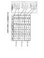
FIG. 2 is a functional block diagram illustrating the configuration of the data dividing device according to the first embodiment. As illustrated in FIG. 2, the
通信制御I/F部11は、他の装置との通信を制御するインタフェースであり、例えばネットワークインタフェースカードなどである。例えば、通信制御I/F部11は、ストリームデータ発生装置1からストリームデータを受信して制御部13に出力する。また、通信制御I/F部11は、ユーザ端末5からデータ取得要求を受信して制御部13に出力し、制御部13から出力されたデータをユーザ端末5に送信する。 The communication control I /
記憶部12は、制御部13が実行するプログラムやデータを記憶するとともに、受信済みDB12aと分割境界DB12bとを有する。なお、記憶部12は、制御部13が有する各種処理部が処理を実行する際にデータを一時的に格納する作業領域等も有する。 The storage unit 12 stores programs and data executed by the
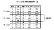
受信済みDB12aは、前後のデータを特定する前後情報を対応付けた複数のデータを記憶するデータベースである。つまり、受信済みDB12aは、所定の順序で整列させたストリームデータを記憶するデータベースである。図3は、受信済みDBに記憶される情報の例を示す図である。図3に示すように、受信済みDB12aは、「時刻、名前、年齢、年収(万円)、支払(円)」を1レコードとして記憶する。ここで記憶される「時刻」は、当該ストリームデータを受信した時刻であり、「名前」は、POSデータとして通知されたユーザの名前である。「年齢」は、ユーザの年齢であり、「年収」は、ユーザの年収であり、「支払」は、ユーザが支払った金額である。なお、ここで示した情報はあくまで例示であり、これに限定されるものではなく、任意に設定変更することができる。 The received
実施例1では、図3に示すように、受信済みDB12aは、年収で昇順にソートされた情報を記憶するが、これに限定されるものではなく、任意にソート対象等を変更できる。図3の場合には、時刻「9」に受信された年収「1200万円」の「Iris」を先頭にして、「Dick」、「Erik」、「Henry」、「George」、「Bob」、「Alice」、「Caren」、「Frank」の順番で記憶する。 In the first embodiment, as shown in FIG. 3, the received
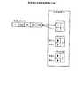
次に、受信済みDB12aがデータを記憶する実装例を説明する。図4は、受信済みDBの実装例を示す図である。図4に示すように、受信済みDB12aは、データに当該データの前後のデータを特定するポインタを対応付けて記憶する。具体的には、時刻9のIrisには、前データのポインタとしてNULLが対応付けられているとともに、後ろデータのポインタとして時刻4のDickが対応付けられている。同様に、時刻4のDickには、前データのポインタとして時刻9のIrisが対応付けられているとともに、後ろデータのポインタとして時刻5のErikが対応付けられている。同様に、時刻5のErikには、前データのポインタとして時刻4のDickが対応付けられているとともに、後ろデータのポインタとして時刻8のHenryが対応付けられている。同様に、時刻8のHenryには、前データのポインタとして時刻5のErikが対応付けられているとともに、後ろデータのポインタとしてNULLが対応付けられている。なお、実装例はあくまで例であり、これに限定されるものではない。 Next, an implementation example in which the received
ここで、実施例1の説明に用いる用語について説明する。実施例1では、ソート後に均等分割された個々のデータ集合を「バケット」と呼ぶ。また、各バケットの境を「分割境界」と呼ぶ。また、「均等分割」とは、データ数Nが分割数Mで割り切れない場合に、各バケットの大きさの差がたかだか1となるように分割することを言う。つまり、データ数が10で分割数が3の場合には、「2」、「3」、「5」などのように分割されたデータ数の差が2以上になるように分割することではなく、「3」、「3」、「4」などのように分割されたデータ数の差が1以下に分割することをいう。なお、属するデータ数が多いバケットを「大バケット」と呼び、小さい方のバケットを「小バケット」と呼ぶ。また、データ数Nが分割数Mで割り切れる場合は、全バケットの大きさが等しくなるよう均等分割を行い、このときは、便宜上、全バケットを「小バケット」とみなす。 Here, terms used for describing the first embodiment will be described. In the first embodiment, each data set that is equally divided after sorting is referred to as a “bucket”. Further, the boundary of each bucket is referred to as a “division boundary”. “Equal division” means that the division is performed so that the difference in size between the buckets is at most 1 when the number of data N cannot be divided by the number of divisions M. That is, when the number of data is 10 and the number of divisions is 3, the division is not performed so that the difference in the number of divided data becomes 2 or more, such as “2”, “3”, “5”, etc. , “3”, “3”, “4” and the like, the difference in the number of divided data is divided into 1 or less. Note that a bucket having a large number of data belongs is called a “large bucket”, and a smaller bucket is called a “small bucket”. In addition, when the number of data N is divisible by the number of divisions M, equal division is performed so that the sizes of all buckets are equal. In this case, for convenience, all buckets are regarded as “small buckets”.
続いて、上記用語の具体例を説明する。図5は、バケットおよび分割境界を説明する図である。図5に示す例は、時刻1から9までのストリームデータを年収でソートして昇順に並べた例である。この例では、データ数が9個であることより、各バケットに属するデータ数が3個となる。具体的には、データ分割装置10は、時刻9、時刻4、時刻5をバケット(D1)、時刻8、時刻7、時刻2をバケット(D2)、時刻1、時刻6、時刻3をバケット(D3)に分割する。また、バケット(D1)とバケット(D2)との境界およびバケット(D2)とバケット(D3)との境界各々が分割境界となる。Subsequently, specific examples of the above terms will be described. FIG. 5 is a diagram for explaining buckets and division boundaries. The example shown in FIG. 5 is an example in which stream data from
図2に戻り、分割境界DB12bは、分割境界を特定する情報を記憶するデータベースである。図6は、分割境界DBに記憶される情報の例を示す図である。図6に示すように、分割境界DB12bは、「バケット名、データ数(サイズ)、先頭情報、末尾情報」を対応付けて記憶する。ここで記憶される「バケット名」は、バケットを識別する識別子であり、例えばバケットの名称などである。「データ数(サイズ)」は、バケットに属するデータの数であり、データ数が3個の場合にはサイズが3である。「先頭情報」は、バケットに属するデータの先頭を示すポインタであり、例えば「時刻」などデータを識別できる任意の項目や、該当データの論理アドレスなどで指定できる。「末尾情報」は、バケットに属するデータの末尾を示すポインタであり、例えば「時刻」などデータを識別できる任意の項目や、該当データの論理アドレスなどで指定できる。実施例1では、「先頭情報」および「末尾情報」として「時刻」を用いることとする。 Returning to FIG. 2, the
なお、サイズ0およびサイズ1のバケットの情報は、便宜上、以下を満たすように分割境界DB12bに格納することを仮定する。サイズ0のバケットに対応する「先頭情報」と「末尾情報」は、共に「NULL」とする。分割境界DBにおいて「先頭情報」および「末尾情報」として格納される「NULL」は、便宜上、受信済みDB12aの最終データの1つ下にある仮想的な末端データを表わしているとみなす。また、サイズ1のバケットに対応する「先頭情報」と「末尾情報」には、共に、そのバケットに唯一含まれるデータが格納される。 For convenience, it is assumed that the
図6の例は、バケット(D1)には、時刻9のデータから時刻5のデータまでの3つのデータが属することを示す。バケット(D2)には、時刻8のデータから時刻2のデータまでの3つのデータが属することを示す。バケット(D3)には、時刻1のデータから時刻6のデータまでの3つのデータが属することを示す。なお、図6に示したデータベースの例はあくまで例示であり、これに限定されるものではなく、例えば図3と同様の実装形式を用いることもでき、他のデータ形式を用いることもできる。同様に、ソート済みのストリームデータ群についても任意のデータ形式を用いることができる。The example of FIG. 6 indicates that three data from
制御部13は、データ分割装置10を全体的に制御する処理部であり、分割数設定部14と分割処理部15と出力部21とを有する。分割数設定部14は、ユーザ端末5等から分割数を受け付けて、分割処理部15に通知する処理部である。例えば、分割数設定部14は、ユーザ端末5から分割数「3」を受け付けると、受け付けた分割数を分割処理部15に通知し、記憶部12の作業領域等に格納する。また、分割数設定部14は、ソート対象とするデータ項目をユーザ端末5等から分割数を受け付けて、分割処理部15に通知する。 The
分割処理部15は、受信部16と位置特定部17と格納制御部18とバケット判定部19と更新部20とを有し、これらによって、受信済みのストリームデータを均等分割する処理部である。 The
受信部16は、ストリームデータ発生装置1からストリームデータを受信する処理部である。受信部16は、ストリームデータ発生装置1からストリームデータを受信し、受信したストリームデータを位置特定部17に出力する。なお、受信部16は、受信したストリームデータを受信順に記憶部12の作業領域等に格納してもよい。 The receiving unit 16 is a processing unit that receives stream data from the stream
位置特定部17は、受信部16が受信したストリームデータに対して、受信済みDB12aへの挿入位置を特定し、特定した結果を格納制御部18に通知する処理部である。例えば、位置特定部17は、受信されたストリームデータからソート対象のデータ項目を特定し、該当する値を抽出する。そして、位置特定部17は、受信済みDB12aに記憶されるストリームデータの各レコードにおけるソート対象のデータ項目を参照し、抽出した値の挿入位置を特定する。 The position specifying unit 17 is a processing unit that specifies an insertion position in the received
具体的な例を挙げると、位置特定部17は、図3に示したデータが受信済みDB12aに記憶されている状態で、「時刻、名前、年齢、年収、支払」として「10、Jane、45、900、2300」を受信したとする。この場合、位置特定部17は、受信したストリームデータからソート対象の項目である「年収」を特定し、該当する値として「900」を抽出する。その後、位置特定部17は、受信済みDB12aに記憶されるストリームデータの各レコードにおけるソート対象のデータ項目を参照し、年収「1000」のレコードと年収「800」のレコードの間が、抽出した「900」の挿入位置であると特定する。 As a specific example, the position specifying unit 17 stores “10, Jane, 45” as “time, name, age, annual income, payment” in a state where the data illustrated in FIG. 3 is stored in the received DB 12a. , 900, 2300 ". In this case, the position specifying unit 17 specifies “annual income” that is an item to be sorted from the received stream data, and extracts “900” as a corresponding value. Thereafter, the position specifying unit 17 refers to the data item to be sorted in each record of the stream data stored in the received
別例を挙げると、位置特定部17は、受信されたストリームデータを記憶部12の作業領域に格納し、この時点で受信済みデータをソートして並び替える。そして、位置特定部17は、並び替えたデータと受信済みDB12aに記憶されるストリームデータとを比較して、受信されたストリームデータの挿入位置を判定することもできる。 As another example, the position specifying unit 17 stores the received stream data in the work area of the storage unit 12, and sorts and rearranges the received data at this time. Then, the position specifying unit 17 can determine the insertion position of the received stream data by comparing the rearranged data and the stream data stored in the received
さらに別例を挙げると、位置特定部17は、図3に示した受信済みDB12aと図6に示した分割境界DB12bが与えられた状態で、「時刻、名前、年齢、年収、支払」として「10、Jane、45、900、2300」を受信したとする。この場合、位置特定部17は、受信したストリームデータからソート対象の項目である「年収」を特定し、該当する値として「900」を抽出する。その後、位置特定部17は、分割境界DB12bに登録された各バケットの「先頭情報」と「末尾情報」を参照し、さらに受信済みDB12aを参照することにより、各バケットの先頭データと末尾データにおける年収を抽出し、挿入されるバケットをまずは特定する。具体的には、バケットD1の先頭データと末尾データの年収は、それぞれ「1200」と「800」であるので、「900」の挿入されるバケットはD1であることを特定する。そして、受信済みDB12aにおけるバケットD1の先頭データから末尾データまでをさらに参照することで、年収「1000」のレコードと年収「800」のレコードの間が、抽出した「900」の挿入位置であると特定する。また、受信したデータがどのバケットにも挿入されない場合として、隣接するバケットの境界に挿入される場合と、受信済みDBの先頭または末尾に挿入される場合があるが、いずれの場合も、分割境界DB12bの「先頭情報」と「末尾情報」を用いて、データの挿入位置を特定することができる。As another example, the position specifying unit 17 is given as “time, name, age, annual income, payment” with the received
格納制御部18は、受信済みDB12aにデータを格納する場合に、当該データが有する項目に基づいて当該データの前後となるデータを特定し、当該前後のデータを特定する前後情報を対応付けて受信済みDB12aに格納する処理部である。言い換えると、格納制御部18は、位置特定部17によって特定された挿入位置に、受信部16によって受信されたストリームデータを挿入する処理部である。 When storing data in the received
上記例で説明すると、年収「1000」のレコードと年収「800」のレコードの間が挿入位置として特定されたとする。この場合、格納制御部18は、受信された「10、Jane、45、900、2300」を年収「1000」のレコードと年収「800」のレコードの間に挿入する。このとき、格納制御部18は、年収「1000」のレコードに対応付けられる前後情報のうち、後ろのポインタを「時刻5、Erik」から「時刻10、Jane」に変更する。また、格納制御部18は、年収「800」のレコードに対応付けられる前後情報のうち、前のポインタを「時刻4、Dick」から「時刻10、Jane」に変更する。そして、格納制御部18は、データ「10、Jane、45、900、2300」に対しては、前後情報として前のポインタを「時刻4 Dick」、後ろのポインタを「時刻5、Erik」を格納する。このようにして、格納制御部18は、受信済みDB12aに新たなデータを格納する。なお、格納制御部18は、新たなストリームデータを受信済みDB12aに格納したことをバケット判定部19に通知する。 In the above example, it is assumed that the insertion position is specified between the record with the annual income “1000” and the record with the annual income “800”. In this case, the
バケット判定部19は、受信済みDB12aに記憶されるデータをグループ化する各バケットが小バケットか大バケットかを判定する処理部である。例えば、バケット判定部19は、格納制御部18によってデータが格納された場合に、各バケットに属するデータ数をスキャンするとともに、受信済みDB12aや分割境界DB12bを参照し、各バケットの大小を特定する。そして、バケット判定部19は、特定した情報を更新部20に通知する。 The
更新部20は、拡張実行部20aと縮退実行部20bとスライド実行部20cとを有する。更新部20は、これらの処理部によって、格納制御部18によってデータが挿入された場合に、各グループに属するデータ数の差が1つ以下となるように、分割境界DB12bに記憶されるグループごとの先頭情報と末尾情報とを更新する。 The
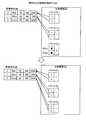
拡張実行部20aは、指定したバケットを上または下方向に拡張し、分割境界DB12bを拡張させた後のバケット情報に更新する処理部である。図7は、バケットの拡張例1を説明する図である。図7に示すように、拡張実行部20aは、バケット判定部19の判定結果に基づいてバケット(Dp)を上方向に拡張させると判定する。この場合、拡張実行部20aは、バケット(Dp)の先頭情報を1件上のデータに置き換えてデータ数を1つ増やして、バケット(Dp)を上方向に拡張させる。このように、バケット(Dp)を上方向に拡張させる方法をupexpand(p)と呼ぶ。また、図7に示した空白はソートされたレコード(データ)を示す。なお、拡張実行部20aがバケットDpを上方向に拡張させると判定する例については、フローの説明で詳細に説明する。The
また、図8は、バケットの拡張例2を説明する図である。図8に示すように、拡張実行部20aは、バケット判定部19の判定結果に基づいてバケット(Dp)を下方向に拡張させると判定する。この場合、拡張実行部20aは、バケット(Dp)の末尾情報を1件下のデータに置き換えてデータ数を1つ増やして、バケット(Dp)を下方向に拡張させる。このように、バケット(Dp)を下方向に拡張させる方法をdownexpand(p)と呼ぶ。また、図8に示した空白はソートされたレコード(データ)を示す。なお、拡張実行部20aがバケットDpを下方向に拡張させると判定する例については、フローの説明で詳細に説明する。FIG. 8 is a diagram for explaining an expansion example 2 of the bucket. As illustrated in FIG. 8, the
縮退実行部20bは、指定したバケットを上または下方向に縮退させ、分割境界DB12bを縮退させた後のバケット情報に更新する処理部である。図9は、バケットの縮退例1を説明する図である。図9に示すように、縮退実行部20bは、バケット判定部19の判定結果に基づいてバケット(Dp)を上方向に縮退させると判定する。この場合、縮退実行部20bは、バケット(Dp)の末尾情報を1件上のデータに置き換えてデータ数を1つ減らし、バケットDpを上方向に縮退させる。このように、バケット(Dp)を上方向に縮退させる方法をupshrink(p)と呼ぶ。また、図9に示した空白はソートされたレコード(データ)を示す。The
また、図10は、バケットの縮退例2を説明する図である。図10に示すように、縮退実行部20bは、バケット判定部19の判定結果に基づいてバケット(Dp)を下方向に縮退させると判定する。この場合、縮退実行部20bは、バケット(Dp)の先頭情報を1件下のデータに置き換えてデータ数を1つ減らしバケット(Dp)を下方向に縮退させる。このように、バケットDpを下方向に縮退させる方法をdownshrink(p)と呼ぶ。また、図10に示した空白はソートされたレコード(データ)を示す。なお、縮退実行部20bがバケットDpを上方向または下方向に縮退させると判定する例については、フローの説明で詳細に説明する。FIG. 10 is a diagram for explaining a degeneration example 2 of the bucket. As illustrated in FIG. 10, the
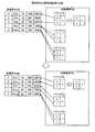
スライド実行部20cは、各バケットに属するデータ数を変えることなく、連続した複数のバケットを上方向または下方向に1ずつずらす処理部である。図11は、バケットのスライド例1を説明する図である。図11に示すように、スライド実行部20cは、バケット判定部19の判定結果に基づいてバケット(Dp)からバケット(Dq)までを上にスライドさせると判定する。この場合、スライド実行部20cは、バケット(Dp)からバケット(Dq)に対して、各バケットの大きさを変えることなく、データを上へ1件ずつずらす操作を行う。すなわち、スライド実行部20cは、対象となるバケット(Dp)からバケット(Dq)各々の先頭および末尾情報を、それぞれ1件上のデータに置き換える。なお、ここではp<qと仮定する。このように、バケット(Dp)からバケット(Dq)を上方向にスライドさせる方法をupslide(p、q)と呼ぶ。また、図11に示した空白はソートされたレコード(データ)を示す。The
また、図12は、バケットのスライド例2を説明する図である。図12に示すように、スライド実行部20cは、バケット判定部19の判定結果に基づいてバケット(Dp)からバケット(Dq)までを下にスライドさせると判定する。この場合、スライド実行部20cは、バケット(Dp)からバケット(Dq)に対して、各バケットの大きさを変えることなく、データを下へ1件ずつずらす操作を行う。すなわち、スライド実行部20cは、対象となるバケット(Dp)からバケット(Dq)各々の先頭および末尾情報を、それぞれ1件下のデータに置き換える。なお、ここではp<qと仮定する。このように、バケット(Dp)からバケット(Dq)を下方向にスライドさせる方法をdownslide(p、q)と呼ぶ。また、図12に示した空白はソートされたレコード(データ)を示す。なお、スライド実行部20cが各バケットを上方向または下方向にスライドさせると判定する例については、フローの説明で詳細に説明する。FIG. 12 is a diagram for explaining a second sliding example of the bucket. As illustrated in FIG. 12, the
出力部21は、受信済みDB12aに記憶されるデータが分割されるグループのうち、ユーザに指定されたグループの先頭情報と末尾情報とを分割境界DB12bから読み出す。そして、出力部21は、読み出した先頭情報に該当するデータから末尾情報に該当するデータまでのデータを受信済みDB12aから読み出して、所定の装置に出力する処理部である。 The
例えば、出力部21がユーザ端末5からバケット(D1)からバケット(D2)の出力依頼を受信したとする。この場合、出力部21は、まず、バケット(D1)の先頭情報と末尾情報を分割境界DB12bから取得する。続いて、出力部21は、取得した先頭情報によって特定されるレコードから、末尾情報によって特定されるレコードまでに位置する各レコードを読み出す。その後、出力部21は、読み出した各レコードをバケット(D1)のデータとしてユーザ端末5に送信する。For example, it is assumed that the
続いて、出力部21は、バケット(D2)の先頭情報と末尾情報を分割境界DB12bから取得する。続いて、出力部21は、取得した先頭情報によって特定されるレコードから、末尾情報によって特定されるレコードまでに位置する各レコードを読み出す。その後、出力部21は、読み出した各レコードをバケット(D2)のデータとしてユーザ端末5に送信する。Subsequently, the
[処理の流れ]
次に、図13から図16を用いてデータ分割装置10が実行する処理の流れを説明する。まず、全体的な処理の流れを説明し、次に、サブフローなどの各処理について説明する。[Process flow]
Next, the flow of processing executed by the
(全体的な処理の流れ)
図13は、データ分割装置によるデータ分割から出力までの一連の流れを示すフローチャートである。なお、ここでは、受信部16が、受信したストリームデータを順番に記憶部12の作業領域等に格納している例で説明する。また、記憶されるストリームデータをS[i](iは自然数)とする。(Overall processing flow)
FIG. 13 is a flowchart showing a series of flow from data division to output by the data division device. Here, an example in which the reception unit 16 stores the received stream data in the work area of the storage unit 12 in order will be described. The stored stream data is S [i] (i is a natural number).
図13に示すように、格納制御部18は、記憶されるストリームデータの先頭のデータであるS[1]を記憶部12から読み出して受信済みDB12aの先頭バケットに格納する(S101)。 As shown in FIG. 13, the
続いて、位置特定部17は、iをインクリメントしてi=2とし(S102)、ストリームデータS[i]が記憶部12の作業領域等に格納されているか否かを判定する(S103)。そして、位置特定部17は、ストリームデータS[i]が存在しない場合は(S103否定)、処理を終了する。 Subsequently, the position specifying unit 17 increments i to i = 2 (S102), and determines whether the stream data S [i] is stored in the work area or the like of the storage unit 12 (S103). If the stream data S [i] does not exist (No at S103), the position specifying unit 17 ends the process.
一方、ストリームデータS[i]が存在する場合は(S103肯定)、位置特定部17は、ストリームデータS[i]を作業領域等から読み込み(S104)、ソート対象の項目にしたがって、受信済みDB12aにおける挿入位置(j)を特定する。そして、格納制御部18は、位置特定部17が特定した挿入位置(j)にストリームデータS[i]を挿入する(S105)。つまり、格納制御部18は、挿入したストリームデータS[i]の前後情報と、挿入位置の前後のデータ各々の前後情報とを更新する。 On the other hand, when the stream data S [i] exists (Yes in S103), the position specifying unit 17 reads the stream data S [i] from the work area or the like (S104), and receives the received
その後、バケット判定部19と更新部20とは、分割境界更新処理を実行して、バケットの分割境界を更新する(S106)。当該処理が終了した後、現在の時刻iの時点で出力要求を受信した場合には(S107肯定)、出力部21は、ユーザ端末5から指示されたバケットに該当するデータを受信済みDB12aから読み出して、ユーザ端末5に出力する(S108)。 Thereafter, the
そして、位置特定部17は、iをインクリメントした後(S109)、S103以降の処理を繰り返す。また、S107において出力要求を受信していない場合には(S107否定)、位置特定部17は、S108を実行することなく、S109を実行する。 Then, the position specifying unit 17 increments i (S109), and then repeats the processes after S103. If the output request is not received in S107 (No in S107), the position specifying unit 17 executes S109 without executing S108.
(分割境界更新処理の流れ)
図14は、データ分割装置による分割境界更新処理の流れを示すフローチャートである。図14に示すように、バケット判定部19は、新たなデータ(以下、挿入データ(d)と呼ぶ)がバケット(Dp)の内部に挿入されたか否かを判定する(S201)。(Division boundary update process flow)
FIG. 14 is a flowchart showing the flow of the division boundary update processing by the data division device. As shown in FIG. 14, the
例えば、バケット判定部19は、挿入されたデータがどの時刻とどの時刻の間かを受信済みDB12aを参照して特定する。続いて、バケット判定部19は、受信済みDB12aと分割境界DB12bを参照して、特定した両時刻の位置がいずれかのバケットの内部か否かを判定する。 For example, the
一例として、図4と図5に示したデータにおいて、時刻9と時刻4との間に時刻10のデータが挿入されたとする。この場合、バケット判定部19は、挿入された位置が時刻9と時刻4の間であることを、挿入前の受信済みDB12aと挿入後の受信済みDB12aとの比較によって特定する。続いて、バケット判定部19は、図5を参照して、時刻9と時刻4のデータがバケット(D1)に属することを特定し、バケット(D1)には時刻9、時刻4、時刻5のデータが存在することを特定する。この結果、バケット判定部19は、時刻4の後ろに時刻5のデータが存在することから、時刻10のデータがバケット内部に挿入されたと判定する。As an example, in the data shown in FIGS. 4 and 5, it is assumed that data at
図14に戻り、バケット判定部19は、挿入データ(d)がバケット(Dp)の内部に挿入された場合(S201肯定)、データが挿入されたバケットが小バケットか否かを判定する(S202)。Returning to FIG. 14, when the insertion data (d) is inserted into the bucket (Dp ) (Yes in S201), the
一例を挙げると、図5に示したように、全バケットのデータ数が3である状態でバケット(D1)にデータが挿入されたとする。この場合、バケット判定部19は、バケット(D1)のデータ数が4となり、他のバケットとのデータ数の差が1以上であることから、データが挿入されたバケットは大バケットと判定する。別の例としては、バケット(D1)のデータ数が「3」、バケット(D2)のデータ数が「3」、バケット(D3)のデータ数が「2」の状態でバケット(D3)にデータが挿入されたとする。この場合、バケット判定部19は、バケット(D3)のデータ数が3となり、他のバケットとのデータ数の差が1未満であることから、データが挿入されたバケットは小バケットと判定する。As an example, as shown in FIG. 5, it is assumed that data is inserted into the bucket (D1 ) in a state where the number of data in all buckets is three. In this case, the
図14に戻り、バケット判定部19がバケット(Dp)を小バケットと判定すると(S202肯定)、更新部20は、「処理1」を実行する(S203)。すなわち、更新部20は、分割境界DB12bに記憶されるバケット(Dp)のデータ数を1増やす。その後、処理を終了する。Returning to FIG. 14, when the
一方、バケット判定部19がバケット(Dp)を大バケットと判定すると(S202否定)、更新部20は、「処理2」を実行し(S204)、処理を終了する。すなわち、更新部20は、分割境界DB12bに記憶されるバケット(Dp)のデータ数を1増やし、バケット(Dp)の一番近くにある小バケットをバケット(Dq)とする。On the other hand, when the
ここで、p<qであるならば、つまり、バケット(Dp)の方がバケット(Dq)よりも上に存在する場合に、更新部20は、upslide(p+1、q−1)、upexpand(q)、upshrink(p)を実行する。具体的には、スライド実行部20cは、バケット(Dp)の1つ下のバケットであるバケット(Dp+1)から、バケット(Dq)の1つ上のバケットであるバケット(Dq−1)までの各バケットの先頭および末尾情報をそれぞれ1件上のデータに置き換える。そして、拡張実行部20aは、バケットDqの先頭情報を1つ上のデータに置き換えてバケットサイズすなわち属するデータ数を1つ増やして、バケットDqを上方向に拡張する。また、縮退実行部20bは、バケットDpの末尾情報を1つ上のデータに置き換えてバケットサイズすなわちデータ数を1つ減らし、バケットDpを上方向に縮退させる。Here, if p <q, that is, if the bucket (Dp ) is higher than the bucket (Dq ), the updating
一方、p>qであるならば、つまり、バケット(Dp)の方がバケット(Dq)よりも下に存在する場合に、更新部20は、downslide(q+1、p−1)、downexpand(q)、downshrink(p)を実行する。具体的には、スライド実行部20cは、バケット(Dq)の1つ下のバケットであるバケット(Dq+1)から、バケット(Dp)の1つ上のバケットであるバケット(Dp−1)までの各バケットの先頭情報および末尾情報をそれぞれ1件下のデータに置き換える。そして、拡張実行部20aは、バケットDqの末尾情報を1つ下のデータに置き換えてデータ数を1つ増やして、バケットDqを下方向に拡張させる。また、縮退実行部20bは、バケットDpの先頭情報を1つ下のデータに置き換えてデータ数を1つ減らし、バケットDpを下方向に縮退させる。On the other hand, if p> q, that is, if the bucket (Dp ) exists below the bucket (Dq ), the updating
図14に戻り、バケット判定部19は、挿入データ(d)がバケット(Dp)の内部に挿入されていないと判定した場合(S201否定)、挿入データ(d)がバケット(Dp)とバケット(Dp+1)の間に挿入されたか否かを判定する(S205)。Returning to FIG. 14, when the
一例として、図4と図5に示したデータを用いて説明すると、バケット判定部19は、時刻5と時刻8の間、または、時刻2と時刻1の間に新たなデータが挿入された場合に、挿入データ(d)がバケットの間に挿入されたと判定する。具体的には、バケット判定部19は、分割境界DB12bを参照し、挿入データ(d)の挿入位置がバケット(Dp)の末尾情報とバケット(Dp+1)の先頭情報の間に位置する場合に、バケットの間に挿入されたと判定する。As an example, using the data shown in FIG. 4 and FIG. 5, when the
図14に戻り、更新部20は、バケット判定部19によって挿入データ(d)がバケット(Dp)とバケット(Dp+1)の間に挿入されたと判定された場合(S205肯定)、サブフロー1を実行する(S206)。一方、更新部20は、バケット判定部19によって挿入データ(d)がバケット(Dp)とバケット(Dp+1)の間に挿入されていないと判定された場合(S205否定)、サブフロー2を実行する(S207)。Returning to FIG. 14, when the updating
(サブフロー1の流れ)
図15は、分割境界更新処理のサブフロー1の流れを示すフローチャートである。図15に示すように、バケット(Dp)が小バケットであると、バケット判定部19によって判定された場合(S301肯定)、更新部20は、「処理3」を実行する(S302)。すなわち、更新部20は、分割境界DB12bに記憶されるバケット(Dp)の末尾情報を挿入データ(d)の情報に修正して、データ数を1増やす。(
FIG. 15 is a flowchart showing the flow of
一方、バケット判定部19は、バケット(Dp)が小バケットでないと判定した場合(S301否定)、バケット(Dp)とバケット(Dp+1)がともに大バケットであるか否かを判定する(S303)。そして、バケット(Dp)とバケット(Dp+1)がともに大バケットであると、バケット判定部19によって判定された場合(S303肯定)、更新部20は、「処理4」を実行する(S304)。On the other hand, when the
すなわち、更新部20は、バケット(Dp)またはバケット(Dp+1)の一番近くに位置する小バケットをDqとする。そして、p+1<qであるならば、つまり、バケット(Dp)の1つ下のバケット(Dp+1)の方がバケット(Dq)よりも上に存在する場合に、更新部20は、upslide(p+1、q−1)、upexpand(q)を実行する。具体的には、スライド実行部20cは、バケット(Dp)の1件下のバケットであるバケット(Dp+1)から、バケット(Dq)の1件上のバケットであるバケット(Dq−1)までの各バケットの先頭情報および末尾情報をそれぞれ1件上のデータに置き換える。さらに、拡張実行部20aは、バケット(Dq)の先頭情報を1件上のデータに置き換えてデータ数を1つ増やし、バケット(Dq)を上方向に拡張する。That is, the updating
また、p>qであるならば、つまり、バケット(Dp)の方がバケット(Dq)よりも下に存在する場合に、更新部20は、downslide(p、q+1)、downexpand(q)を実行する。具体的には、スライド実行部20cは、バケット(Dp)から、バケット(Dq)の1件下のバケットであるバケット(Dq+1)までの各バケットの先頭情報および末尾情報をそれぞれ1件下のデータに置き換える。さらに、拡張実行部20aは、バケット(Dq)の先頭情報を1件下のデータに置き換えてデータ数を1つ増やし、バケット(Dq)を下方向に拡張する。If p> q, that is, if the bucket (Dp ) exists below the bucket (Dq ), the updating
図15に戻り、バケット(Dp+1)が大バケットでないとバケット判定部19によって判定された場合(S303否定)、更新部20は、「処理5」を実行する(S305)。すなわち、更新部20は、分割境界DB12bに記憶されるバケット(Dp+1)の先頭情報を挿入データ(d)の情報に修正して、データ数を1増やす。Returning to FIG. 15, when it is determined by the
(サブフロー2の流れ)
図16は、分割境界更新処理のサブフロー2の流れを示すフローチャートである。図16に示すように、バケット判定部19は、受信済みDB12aを参照して挿入データ(d)の挿入位置が全データの先頭であると判定した場合(S401肯定)、先頭バケット(D1)が大バケットであるか否かを判定する(S402)。(
FIG. 16 is a flowchart showing the flow of
そして、バケット判定部19が分割境界DB12b等を参照して先頭バケット(D1)が大バケットであると判定した場合(S402肯定)、更新部20は、「処理6」を実行する(S403)。If the
すなわち、更新部20は、分割境界DB12bに記憶されるバケット(D1)の先頭情報を挿入データ(d)に修正して、データ数を1増やし、バケット(D1)の一番近くに位置する小バケットを(Dp)とする。その後、更新部20は、upshrink(1)とupslide(2、q−1)とupexpand(q)を実行する。具体的には、縮退実行部20bは、分割境界DB12bに記憶されるバケット(D1)の末尾情報を1件上のデータに置き換えて、データ数を1減らす。また、スライド実行部20cは、分割境界DB12bにおいてバケット(D2)からバケット(Dq−1)までの各バケットの先頭情報および末尾情報をそれぞれ1件上のデータに置き換える。また、拡張実行部20aは、分割境界DB12bにおいてバケット(Dq)の先頭情報を1件上のデータに置き換えて、データ数を1増やす。That is, the
一方、バケット判定部19が分割境界DB12b等を参照して先頭バケット(D1)が大バケットではないと判定した場合(S402否定)、更新部20は、「処理7」を実行する(S404)。すなわち、更新部20は、分割境界DB12bにおいて、先頭バケット(D1)の先頭情報を挿入データ(d)の情報に修正して、データ数を1増やす。On the other hand, when the
また、S401において、バケット判定部19は、受信済みDB12aを参照して挿入データ(d)の挿入位置が全データの先頭でないと判定した場合(S401否定)、末尾バケット(Dm)が大バケットであるか否かを判定する(S405)。つまり、バケット判定部19は、挿入データ(d)の挿入位置が末尾であると判定した場合、末尾バケット(Dm)が大バケットであるか否かを判定する。In S401, if the
そして、バケット判定部19が分割境界DB12b等を参照して末尾バケット(Dm)が大バケットであると判定した場合(S405肯定)、更新部20は、「処理8」を実行する(S406)。すなわち、更新部20は、分割境界DB12bにおいて、末尾バケット(Dm)の末尾情報を挿入データ(d)の情報に修正して、データ数を1増やす。If the
一方、バケット判定部19が分割境界DB12b等を参照して末尾バケット(Dm)が大バケットでないと判定した場合(S405否定)、更新部20は、「処理9」を実行する(S407)。On the other hand, when the
すなわち、更新部20は、分割境界DB12bに記憶される末尾バケット(Dm)の末尾情報を挿入データ(d)の情報に修正してデータ数を1増やし、末尾バケット(Dm)の一番近くに位置する小バケットを(Dq)とする。その後、更新部20は、downshrink(m)とdownslide(q+1、m−1)とdownexpand(q)を実行する。That is, the
具体的には、縮退実行部20bは、分割境界DB12bに記憶されるバケット(Dm)の先頭情報を1件下のデータに修正して、データ数を1減らす。また、スライド実行部20cは、分割境界DB12bにおいて、バケット(Dq+1)からバケット(Dm−1)までの各バケットの先頭情報および末尾情報をそれぞれ1件下のデータに置き換える。また、拡張実行部20aは、分割境界DB12bにおいて、バケット(Dq)の末尾情報を1件下のデータに置き換えて、データ数を1増やす。Specifically, the
[データ分割の具体例]
次に、図17から図28を用いて、ストリームデータを受信して分割境界を更新する一連の処理の具体例を説明する。まず、具体例の説明に用いるデータ例等について説明する。図17は、具体例として取り上げるストリームデータの例を示す図である。図18は、具体例として取り上げる分割境界の例を示す図である。[Specific example of data division]
Next, a specific example of a series of processes for receiving stream data and updating the division boundary will be described with reference to FIGS. First, an example of data used to explain a specific example will be described. FIG. 17 is a diagram illustrating an example of stream data taken as a specific example. FIG. 18 is a diagram illustrating an example of a division boundary taken as a specific example.
ストリームデータ発生装置1は、図17に示すストリームデータのうち時刻1から順にデータ分割装置10に送信し、データ分割装置10の受信部16は、時刻1のストリームデータから順に受信する。ストリームデータは、「時刻、名前、年齢、年収(万円)、支払(円)」の項目を有する。なお、受信されたデータは、年収を降順でソートされるものとする。 The stream
また、データ分割装置10の分割境界DB12bは、図18に示すように、バケットごとに、データ数と先頭情報と末尾情報とを対応付けて記憶する。ここで記憶されるデータ数は、バケットに属するデータの数である。先頭情報は、バケットの先頭に位置するデータであり、当該データの時刻が格納される。末尾情報は、バケットの末尾に位置するデータであり、当該データの時刻が格納される。なお、ここではバケット数を3として説明する。つまり、受信したデータを3つのグループに分割する例を説明する。 Further, as shown in FIG. 18, the
このような状態において、受信部16が、「1、Alice、24、300、1500」とするストリームデータを受信したとする。すると、位置特定部17は、受信済みDB12aにデータが格納されていないことから、当該「Alice」のデータの格納位置を受信済みDB12aの先頭と特定する。そして、格納制御部18は、「Alice」のデータを受信済みDB12aの先頭に格納する。その後、更新部20は、分割境界DB12bを更新する。図19は、具体的な分割例を説明する図である。図19に示すように、更新部20は、先頭のバケットであるバケット(D1)の先頭情報および末尾情報各々に「Alice」のデータを特定する「時刻1」を格納し、バケット(D1)のデータ数を1に更新する。In such a state, it is assumed that the receiving unit 16 has received stream data “1, Alice, 24, 300, 1500”. Then, since the data is not stored in the received
続いて、受信部16が、「2、Bob、55、450、2500」とするストリームデータを受信したとする。すると、位置特定部17は、格納済み「Alice」の年収「300」と受信した「Bob」の年収「1500」を比較し、当該「Bob」のデータの格納位置を受信済みDB12aの先頭と特定する。そして、格納制御部18は、当該「Bob」のデータを受信済みDB12aの先頭に格納する。その後、更新部20は、分割境界DB12bを更新する。図20は、具体的な分割例を説明する図である。図20に示すように、更新部20は、先頭のバケットであるバケット(D1)の先頭情報に「Bob」のデータを特定する「時刻2」を格納し、バケット(D1)のデータ数を2に更新する。Subsequently, it is assumed that the receiving unit 16 receives stream data “2, Bob, 55, 450, 2500”. Then, the location specifying unit 17 compares the annual income “300” of the stored “Alice” with the annual income “1500” of the received “Bob”, and specifies the storage location of the data of “Bob” as the head of the received
ここで、バケット判定部19は、分割境界DB12bの各分割境界を参照し、バケット(D1)のデータ数が他のバケットのデータ数よりも2以上多く、バケット(D1)が大バケットであることを特定して、これらを更新部20に通知する。すると、更新部20は、新たなデータが挿入された位置が受信済みDB12aの先頭であり、先頭であるバケット(D1)が大バケットであることから、「処理6」を実行する。Here, the
すなわち、図20に示すように、更新部20は、バケット(D1)に一番近い小バケットがバケット(D2)であると特定する。つまり、q=2となる。そして、縮退実行部20bは、upshrink(1)を実行し、分割境界DB12bに記憶されるバケット(D1)の先頭情報および末尾情報を「Bob」のデータを特定する「時刻2」に修正し、データ数を1減らして1にする。また、拡張実行部20aは、分割境界DB12bにおいて、バケット(D2)の先頭情報を、仮想の末端データとみなされるNULLに対して1件上の「Alice」の「時刻1」に置き換えて、データ数を1増やす。サイズ1のバケットに関する仮定により、バケット(D2)の末尾情報も「時刻1」に置き換える。このとき、2>q−1となるため、更新部20は、upslide(2、q−1)を実行しない。That is, as illustrated in FIG. 20, the
続いて、受信部16が、「3、Caren、62、200、3000」とするストリームデータを受信したとする。すると、位置特定部17は、格納済み各データの年収と受信した「Caren」の年収「200」を比較し、当該「Caren」のデータの格納位置を受信済みDB12aの末尾と特定する。そして、格納制御部18は、当該「Caren」のデータを受信済みDB12aの末尾に格納する。その後、更新部20は、分割境界DB12bを更新する。図21は、具体的な分割例を説明する図である。図21に示すように、バケット判定部19は、「Caren」のデータの格納位置が末尾であり、格納対象の末尾のバケットが小バケットであると判定する。この結果、更新部20は、「処理8」を実行する。すなわち、更新部20は、分割境界DB12bにおいて、末尾バケット(D3)の末尾情報に「Caren」のデータを特定する「時刻3」を格納して、データ数を1増やす。サイズ1のバケットに関する仮定により、バケット(D3)の先頭情報にも「時刻3」を格納する。Subsequently, it is assumed that the receiving unit 16 receives stream data “3, Caren, 62, 200, 3000”. Then, the position specifying unit 17 compares the annual income “200” of the received “Caren” with the annual income of each stored data, and specifies the storage position of the data of “Caren” as the end of the received
続いて、受信部16が、「4、Dick、53、1000、5500」とするストリームデータを受信したとする。すると、位置特定部17は、格納済み各データの年収と受信した「Dick」の年収「1000」を比較し、当該「Dick」のデータの格納位置を受信済みDB12aの先頭と特定する。そして、格納制御部18は、当該「Dick」のデータを受信済みDB12aの先頭に格納する。その後、更新部20は、分割境界DB12bを更新する。図22は、具体的な分割例を説明する図である。図22に示すように、バケット判定部19は、「Dick」のデータの格納位置が先頭であり、格納対象の先頭のバケットが小バケットであると判定する。この結果、更新部20は、「処理7」を実行する。すなわち、更新部20は、分割境界DB12bにおいて、先頭バケット(D1)の先頭情報に「Dick」のデータを特定する「時刻4」を格納して、データ数を1増やして「2」にする。Subsequently, it is assumed that the receiving unit 16 receives stream data “4, Dick, 53, 1000, 5500”. Then, the location specifying unit 17 compares the annual income of each stored data with the annual income “1000” of the received “Dick”, and specifies the storage location of the data of “Dick” as the head of the received
続いて、受信部16が、「5、Erik、35、800、10000」とするストリームデータを受信したとする。すると、位置特定部17は、格納済みの各データの年収と受信した「Erik」の年収「800」を比較し、当該「Erik」のデータの格納位置を「Dick」と「Bob」の間と特定する。そして、格納制御部18は、受信済みDB12aにおける「Dick」と「Bob」の間に「Erik」のデータを格納する。その後、更新部20は、分割境界DB12bを更新する。図23は、具体的な分割例を説明する図である。図23に示すように、更新部20は、先頭のバケットであるバケット(D1)にデータが追加されたので、バケット(D1)のデータ数を「3」に更新する。Subsequently, it is assumed that the receiving unit 16 receives stream data “5, Erik, 35, 800, 10000”. Then, the location specifying unit 17 compares the annual income “800” of the received “Erik” with the annual income of each stored data, and sets the storage location of the data of “Erik” between “Dick” and “Bob”. Identify. Then, the
ここで、バケット判定部19は、分割境界DB12bの各分割境界を参照し、バケット(D1)のデータ数が他のバケットのデータ数よりも2以上となっていることと、バケット(D1)が大バケットであることを特定して、更新部20に通知する。すると、更新部20は、新たなデータがバケット(D1)の内部に格納され、バケット(D1)が大バケットであることから、「処理2」を実行する。Here, the
すなわち、図23に示すように、更新部20は、バケット(D1)に一番近い小バケットがバケット(D2)であると特定する。つまり、q=2となり、p<qとなる。したがって、縮退実行部20bは、upshrink(1)を実行し、分割境界DB12bに記憶されるバケット(D1)の末尾情報を「Dick」のデータを特定する「時刻5」に修正してデータ数を1減らして「1」にする。また、拡張実行部20aは、upexpand(2)を実行し、分割境界DB12bに記憶されるバケット(D2)の先頭情報を1件上の「Bob」の「時刻2」に置き換えて、データ数を1増やして「2」にする。このとき、p+1>q−1となるため、更新部20は、upslide(p+1、q−1)を実行しない。That is, as illustrated in FIG. 23, the
続いて、受信部16が、「6、Franklin、19、250、300」とするストリームデータを受信したとする。すると、位置特定部17は、格納済みの各データの年収と受信した「Erik」の年収「250」を比較し、当該「Franklin」のデータの格納位置を「Alice」と「Caren」の間と特定する。そして、格納制御部18は、受信済みDB12aにおける「Alice」と「Caren」の間に「Franklin」のデータを格納する。 Subsequently, it is assumed that the receiving unit 16 receives stream data “6, Franklin, 19, 250, 300”. Then, the location specifying unit 17 compares the annual income “250” of the received “Erik” with the annual income of each stored data, and sets the storage location of the “Franklin” data between “Alice” and “Caren”. Identify. Then, the
ここで、バケット判定部19は、受信済みDB12aや分割境界DB12bを参照し、「Franklin」のデータの格納位置がバケット(D2)とバケット(D3)の間であり、バケット(D2)が大バケットで、バケット(D3)が小バケットであると判定する。この判定を受けて、更新部20は、「処理5」を実行する。図24は、具体的な分割例を説明する図である。図24に示すように、更新部20は、分割境界DB12bに記憶されるバケット(D3)の先頭情報を「Franklin」のデータを特定する「時刻6」に修正し、データ数を1増やして「2」に更新する。Here, the
続いて、受信部16が、「7、George、25、600、1300」とするストリームデータを受信したとする。すると、位置特定部17は、格納済みの各データの年収と受信した「George」の年収「600」を比較し、当該「George」のデータの格納位置を「Erik」と「Bob」の間と特定する。そして、格納制御部18は、受信済みDB12aにおける「Erik」と「Bob」の間に「George」のデータを格納する。 Subsequently, it is assumed that the receiving unit 16 receives stream data “7, George, 25, 600, 1300”. Then, the location specifying unit 17 compares the annual income “600” of the received “George” with the annual income of each stored data, and sets the storage location of the data of “George” between “Erik” and “Bob”. Identify. Then, the
ここで、バケット判定部19は、受信済みDB12aや分割境界DB12bを参照し、「George」のデータの格納位置がバケット(D1)とバケット(D2)の間であり、バケット(D1)とバケット(D2)とが共に小バケットであると判定する。この判定を受けて、更新部20は、「処理3」を実行する。図25は、具体的な分割例を説明する図である。図25に示すように、更新部20は、分割境界DB12bに記憶されるバケットD1の末尾情報を「George」のデータを特定する「時刻7」に修正し、データ数を1増やして「3」に更新する。Here, the
続いて、受信部16が、「8、Henry、47、750、8500」とするストリームデータを受信したとする。すると、位置特定部17は、格納済みの各データの年収と受信した「Henry」の年収「750」を比較し、当該「Henry」のデータの格納位置を「Erik」と「George」の間と特定する。そして、格納制御部18は、受信済みDB12aにおける「Erik」と「George」の間に「Henry」のデータを格納する。その後、更新部20は、分割境界DB12bを更新する。図26は、具体的な分割例を説明する図である。図26に示すように、更新部20は、先頭のバケットであるバケットD1にデータが追加されたので、バケットD1のデータ数を4に更新する。Subsequently, it is assumed that the receiving unit 16 receives stream data “8, Henry, 47, 750, 8500”. Then, the location specifying unit 17 compares the annual income “750” of the received “Henry” with the annual income of each stored data, and sets the storage location of the data of “Henry” between “Erik” and “George”. Identify. Then, the
ここで、バケット判定部19は、分割境界DB12bの各分割境界を参照し、バケット(D1)のデータ数が他のバケットのデータ数よりも2以上となっていることと、バケット(D1)が大バケットであることを特定して、更新部20に通知する。すると、更新部20は、新たなデータがバケット(D1)の内部に格納され、バケット(D1)が大バケットであることから、「処理2」を実行する。Here, the
すなわち、図26に示すように、更新部20は、バケット(D1)に一番近い小バケットがバケット(D2)であると特定する。つまり、q=2となり、p<qとなる。したがって、縮退実行部20bは、upshrink(1)を実行し、分割境界DB12bに記憶されるバケット(D1)の末尾情報を「時刻7」から「Henry」のデータを特定する「時刻8」に修正してデータ数を1減らして「3」にする。また、拡張実行部20aは、upexpand(2)を実行し、分割境界DB12bに記憶されるバケット(D2)の先頭情報を「時刻2」から1件上の「George」の「時刻7」に置き換えて、データ数を1増やして「3」にする。このとき、p+1>q−1となるため、更新部20は、upslide(p+1、q−1)を実行しない。That is, as illustrated in FIG. 26, the updating
続いて、受信部16が、「9、Iris、61、1200、7000」とするストリームデータを受信したとする。すると、位置特定部17は、格納済みの各データの年収と受信した「Iris」の年収「1200」を比較し、当該「Iris」のデータの格納位置を受信済みDB12aの先頭と特定する。そして、格納制御部18は、「Iris」のデータを受信済みDB12aの先頭に格納する。その後、更新部20は、分割境界DB12bを更新する。図27は、具体的な分割例を説明する図である。図27に示すように、更新部20は、先頭のバケットであるバケット(D1)の先頭情報に「Iris」のデータを特定する「時刻9」を格納し、バケット(D1)のデータ数を4に更新する。Subsequently, it is assumed that the receiving unit 16 receives stream data “9, Iris, 61, 1200, 7000”. Then, the position specifying unit 17 compares the annual income of each stored data with the annual income “1200” of the received “Iris”, and specifies the storage location of the data of “Iris” as the head of the received
ここで、バケット判定部19は、分割境界DB12bの各分割境界を参照し、バケットD1のデータ数が他のバケットのデータ数よりも2以上多く、バケット(D1)が大バケットであることを特定して、更新部20に通知する。すると、更新部20は、新たなデータが挿入された位置が受信済みDB12aの先頭であり、先頭であるバケット(D1)が大バケットであることから、「処理6」を実行する。Here, it
すなわち、図27に示すように、更新部は、バケット(D1)に一番近い小バケットがバケット(D2)であると特定する。つまり、q=2となる。そして、縮退実行部20bは、upshrink(1)を実行し、分割境界DB12bに記憶されるバケット(D1)の末尾情報を「時刻8」から1件上の「時刻5」に修正し、データ数を1減らして「3」にする。また、スライド実行部20cは、upslide(2、2)を実行し、バケット(D2)の先頭情報を「時刻7」から1件上の「時刻8」に修正し、バケット(D2)の末尾情報を「時刻1」から1件上の「時刻2」に修正する。さらに、拡張実行部20aは、upexpand(3)を実行して、分割境界DB12bに記憶されるバケット(D3)の先頭情報を「時刻6」から1件上の「時刻1」に置き換えて、データ数を1増やして「3」にする。That is, as shown in FIG. 27, the update unit specifies that the small bucket closest to the bucket (D1 ) is the bucket (D2 ). That is, q = 2. Then, the
上述した図19から図27を実行することで、データ分割装置10は、図28に示す分割結果を得ることができる。図28は、具体的な分割例による処理結果を示す図である。図28に示すように、データ分割装置10は、時刻1から時刻9までのデータを順次受信し、受信するたびにソートしながら蓄積する一方で、受信済みデータを均等分割することができる。図28の例では、データ分割装置10が、時刻9、時刻4、時刻5のデータをバケットD1に分割し、時刻8、時刻7、時刻2のデータをバケットD2に分割し、時刻1、時刻6、時刻3のデータをバケットD3に分割した状態を示す。By executing the above-described FIG. 19 to FIG. 27, the
[出力の具体例]
次に、図29から図32を用いて、データ出力の具体例を説明する。図29は、データ分割装置がデータ分割を実行した結果を示す図である。図29に示すように、データ分割装置10が、時刻1から時刻10までのデータを5つのバケットに均等分割したとする。具体的には、データ分割装置10は、時刻9と時刻4のデータをバケット(D1)に分割し、時刻5と時刻8のデータをバケット(D2)に分割し、時刻7と時刻2のデータをバケット(D3)に分割したとする。同様に、データ分割装置10は、時刻10と時刻1のデータをバケット(D4)に分割し、時刻6と時刻3のデータをバケット(D5)に分割したとする。[Specific example of output]
Next, a specific example of data output will be described with reference to FIGS. FIG. 29 is a diagram illustrating a result of data division performed by the data dividing apparatus. As shown in FIG. 29, it is assumed that the
この状態において、データ分割装置10の出力部21は、ユーザ端末5からバケット(D2)とバケット(D3)とバケット(D4)のデータ出力依頼を受信したとする。図30から図32は、具体的なデータ出力例を説明する図である。この場合、まず、出力部21は、図30に示すように、分割境界DB12bに記憶されるバケット(D2)の先頭および末尾情報を参照する。そして、出力部21は、受信済みDB12aにソートされて記憶されるデータのうち「時刻5」から「時刻8」までの間に位置する2つのデータがバケット(D2)に属するデータであると特定する。そして、出力部21は、「時刻5」のレコードである「5、Erik、35、800、10000」と「時刻8」のレコードである「8、Henry、47、750、8500」とを受信済みDB12aから読み出して、ユーザ端末5に送信する。In this state, it is assumed that the
次に、出力部21は、図31に示すように、分割境界DB12bに記憶されるバケット(D3)の先頭および末尾情報を参照する。そして、出力部21は、受信済みDB12aにソートされて記憶されるデータのうち「時刻7」から「時刻2」までの間に位置する2つのデータがバケット(D3)に属するデータであると特定する。そして、出力部21は、「時刻7」のレコードである「7、George、25、600、1300」と「時刻2」のレコードである「2、Bob、55、450、2500」とを受信済みDB12aから読み出して、ユーザ端末5に送信する。Next, as illustrated in FIG. 31, the
最後に、出力部21は、図32に示すように、分割境界DB12bに記憶されるバケット(D4)の先頭および末尾情報を参照する。そして、出力部21は、受信済みDB12aにソートされて記憶されるデータのうち「時刻10」から「時刻1」までの間に位置する2つのデータがバケット(D4)に属するデータであると特定する。そして、出力部21は、「時刻10」のレコードである「10、James、37、400、1700」と「時刻1」のレコードである「1、Alice、24、300、1500」とを受信済みDB12aから読み出して、ユーザ端末5に送信する。Finally, as illustrated in FIG. 32, the
このように、データ分割装置10は、データ分割結果のうちユーザが指定するグループのデータを読み出して応答することができる。 In this way, the
[実施例による効果]
このように、実施例1に係るデータ分割装置10は、バケット数を固定したまま1レコードごとに動的に分割境界を変更するような整列均等分割を実現することができる。つまり、データ分割装置10は、ストリームデータを受信するたびにデータをソートして格納するとともに、データ分割を行うことができる。このとき、データ分割装置10は、ソートした順序を示す連番をデータに割り振ることなく、グループ分けすることができるので、データの分割にかかる時間を短縮できる。つまり、実施例で示す「時刻」のように、レコードを識別する番号を示す「通番」は与えられているが、「連番」が与えられていないデータを、「連番」を与えることなく高速に分割することができる。[Effects of Examples]
As described above, the
データ分割装置10では、データ受信時にデータを分割することができるので、ユーザがデータ分割を要求してから分割するまでに時間がかからず、即時応答することができる。一方、従来技術の場合、均等分割された結果に対して、一部のバケットのみの出力が要求されるような場合には、全データをスキャンしなければならないので、時間がかかる。一方、実施例1に係るデータ分割装置10は、ユーザが要求するバケット内のデータのみスキャンすればよいので、出力時間を短縮できる。 Since the
さて、これまで本発明の実施例について説明したが、本発明は上述した実施例以外にも、種々の異なる形態にて実施されてよいものである。そこで、以下に異なる実施例を説明する。 Although the embodiments of the present invention have been described so far, the present invention may be implemented in various different forms other than the embodiments described above. Therefore, different embodiments will be described below.
(分割と出力)
実施例1では、データ分割とデータ出力とを1つのフローチャートで説明したが、これに限定されるものではない。例えば、データ分割とデータ出力とは全く別の契機で実行させることもできる。つまり、データ分割処理した後にデータ出力処理を実行するのではなく、全く別の処理として実行することができる。また、データ分割装置10は、ユーザ端末5にデータを出力するだけでなく、例えばディスプレイなどの表示部に表示させることもでき、記憶媒体等に書き込むこともできる。(Split and output)
In the first embodiment, data division and data output have been described with one flowchart, but the present invention is not limited to this. For example, data division and data output can be executed at completely different triggers. In other words, the data output processing is not executed after the data division processing, but can be executed as completely different processing. Further, the
(ストリームデータ)
実施例1で説明したストリームデータやデータの構成はあくまで例であり、これに限定するものではない。また、データ分割装置10は、ストリームデータに限ったものではなく、様々なデータに適用することができる。例えば、データ分割装置10は、ストレージ等に格納されるデータや、記憶媒体等から読み出されたデータに対しても同様に分割することができる。(Stream data)
The stream data and data configuration described in the first embodiment are merely examples, and the present invention is not limited to this. Further, the
(システム)
また、本実施例において説明した各処理のうち、自動的におこなわれるものとして説明した処理の全部または一部を手動的におこなうこともできる。あるいは、手動的におこなわれるものとして説明した処理の全部または一部を公知の方法で自動的におこなうこともできる。この他、上記文書中や図面中で示した処理手順、制御手順、具体的名称、各種のデータやパラメータを含む情報については、特記する場合を除いて任意に変更することができる。(system)
In addition, among the processes described in the present embodiment, all or a part of the processes described as being automatically performed can be manually performed. Alternatively, all or part of the processing described as being performed manually can be automatically performed by a known method. In addition, the processing procedure, control procedure, specific name, and information including various data and parameters shown in the above-described document and drawings can be arbitrarily changed unless otherwise specified.
また、図示した各装置の各構成要素は機能概念的なものであり、必ずしも物理的に図示の如く構成されていることを要しない。すなわち、各装置の分散・統合の具体的形態は図示のものに限られない。つまり、その全部または一部を、各種の負荷や使用状況などに応じて、任意の単位で機能的または物理的に分散・統合して構成することができる。さらに、各装置にて行なわれる各処理機能は、その全部または任意の一部が、CPUおよび当該CPUにて解析実行されるプログラムにて実現され、あるいは、ワイヤードロジックによるハードウェアとして実現され得る。 Further, each component of each illustrated apparatus is functionally conceptual, and does not necessarily need to be physically configured as illustrated. That is, the specific form of distribution / integration of each device is not limited to that shown in the figure. That is, all or a part of them can be configured to be functionally or physically distributed / integrated in arbitrary units according to various loads or usage conditions. Further, all or any part of each processing function performed in each device may be realized by a CPU and a program analyzed and executed by the CPU, or may be realized as hardware by wired logic.
(ハードウェア構成)
ところで、上記の実施例で説明した各種の処理は、あらかじめ用意されたプログラムをパーソナルコンピュータやワークステーションなどのコンピュータシステムで実行することによって実現することができる。そこで、以下では、上記の実施例と同様の機能を有するプログラムを実行するコンピュータシステムの一例を説明する。(Hardware configuration)
By the way, the various processes described in the above embodiments can be realized by executing a program prepared in advance on a computer system such as a personal computer or a workstation. Therefore, in the following, an example of a computer system that executes a program having the same function as in the above embodiment will be described.
図33は、データ分割プログラムを実行するコンピュータのハードウェア構成の例を示す図である。図33に示すように、コンピュータ100は、CPU102、入力装置103、出力装置104、通信インタフェース105、媒体読取装置106、HDD(Hard Disk Drive)107、RAM(Random Access Memory)108を有する。また、図33に示した各部は、バス101で相互に接続される。 FIG. 33 is a diagram illustrating an example of a hardware configuration of a computer that executes a data division program. As illustrated in FIG. 33, the
入力装置103は、マウスやキーボードであり、出力装置104は、ディスプレイなどであり、通信インタフェース105は、NIC(Network Interface Card)などのインタフェースである。HDD107は、データ分割プログラム107aとともに、図2に示した各DB等を記憶する。記録媒体の例としてHDD107を例に挙げたが、ROM(Read Only Memory)、RAM、CD−ROM、SSD(Solid State Drive)等の他のコンピュータ読取可能な記録媒体に各種プログラムを格納しておき、コンピュータに読み取らせることとしてもよい。なお、記録媒体を遠隔地に配置し、コンピュータが、その記憶媒体にアクセスすることでプログラムを取得して利用してもよい。また、その際、取得したプログラムをそのコンピュータ自身の記録媒体に格納して用いてもよい。 The
CPU102は、データ分割プログラム107aを読み出してRAM108に展開することで、図2等で説明した各機能を実行するデータ分割プロセス108aを動作させる。すなわち、データ分割プロセス108aは、図2に記載した分割数設定部14、分割処理部15、出力部21と同様の機能を実行する。このようにコンピュータ100は、プログラムを読み出して実行することでデータ分割方法を実行する情報処理装置として動作する。 The
例えば、コンピュータ100は、媒体読取装置106によって記録媒体からデータ分割プログラムを読み出し、読み出されたデータ分割プログラムを実行することで上記した実施例と同様の機能を実現することもできる。なお、この他の実施例でいうプログラムは、コンピュータ100によって実行されることに限定されるものではない。例えば、他のコンピュータまたはサーバがプログラムを実行する場合や、これらが協働してプログラムを実行するような場合にも、本発明を同様に適用することができる。 For example, the
1 ストリームデータ発生装置
5 ユーザ端末
10 データ分割装置
11 通信制御I/F部
12 記憶部
12a 受信済みDB
12b 分割境界DB
13 制御部
14 分割数設定部
15 分割処理部
16 受信部
17 位置特定部
18 格納制御部
19 バケット判定部
20 更新部
20a 拡張実行部
20b 縮退実行部
20c スライド実行部
21 出力部DESCRIPTION OF
12b Partition boundary DB
DESCRIPTION OF
Claims (7)
Translated fromJapanese前記データ記憶部に記憶されるデータが予め定めたグループ数に分割されるグループごとに、当該グループ内の先頭に位置するデータを特定する先頭情報と当該グループ内の末尾に位置するデータを特定する末尾情報とを記憶する情報記憶部と、
前記データ記憶部にデータを格納する場合に、当該データが有する項目に基づいて当該データの前後となるデータを特定し、当該前後のデータを特定する前後情報を対応付けて前記データ記憶部に格納する格納制御部と、
前記格納制御部によってデータが格納された場合に、前記各グループに属するデータ数の差が1つ以下となるように、前記情報記憶部に記憶される前記グループごとの先頭情報と末尾情報とを更新する更新部と
を有することを特徴とするデータ分割装置。A data storage unit for storing a plurality of pieces of data associated with front and rear information for specifying the data before and after;
For each group in which the data stored in the data storage unit is divided into a predetermined number of groups, the head information specifying the data located at the head in the group and the data located at the end in the group are specified. An information storage unit for storing tail information;
When data is stored in the data storage unit, the data before and after the data is specified based on the items included in the data, and the before / after information specifying the data before and after is associated and stored in the data storage unit A storage control unit,
When the data is stored by the storage control unit, the head information and end information for each group stored in the information storage unit are stored so that the difference in the number of data belonging to each group is 1 or less. And a data division device comprising: an update unit for updating.
前後のデータを特定する前後情報を対応付けた複数のデータを記憶するデータ記憶部にデータを格納する場合に、当該データが有する項目に基づいて当該データの前後となるデータを特定し、当該前後のデータを特定する前後情報を対応付けて前記データ記憶部に格納し、
前記データが格納された場合に、前記各グループに属するデータ数の差が1つ以下となるように、前記データ記憶部に記憶されるデータが予め定めたグループ数に分割されるグループごとに当該グループ内の先頭に位置するデータを特定する先頭情報と当該グループ内の末尾に位置するデータを特定する末尾情報とを記憶する情報記憶部における前記グループごとの先頭情報と末尾情報とを更新する
処理を含んだことを特徴とするデータ分割方法。Computer
When data is stored in a data storage unit that stores a plurality of pieces of data that are associated with before and after information that identifies data before and after, the data before and after the data is specified based on the items that the data has, Before and after the information specifying the data is associated and stored in the data storage unit,
For each group in which the data stored in the data storage unit is divided into a predetermined number of groups so that the difference in the number of data belonging to each group becomes one or less when the data is stored Processing for updating head information and tail information for each group in an information storage unit that stores head information for identifying data located at the head in the group and tail information for identifying data located at the tail in the group A data partitioning method characterized by comprising:
前後のデータを特定する前後情報を対応付けた複数のデータを記憶するデータ記憶部にデータを格納する場合に、当該データが有する項目に基づいて当該データの前後となるデータを特定し、当該前後のデータを特定する前後情報を対応付けて前記データ記憶部に格納し、
前記データが格納された場合に、前記各グループに属するデータ数の差が1つ以下となるように、前記データ記憶部に記憶されるデータが予め定めたグループ数に分割されるグループごとに当該グループ内の先頭に位置するデータを特定する先頭情報と当該グループ内の末尾に位置するデータを特定する末尾情報とを記憶する情報記憶部における前記グループごとの先頭情報と末尾情報とを更新する
処理を実行させることを特徴とするデータ分割プログラム。On the computer,
When data is stored in a data storage unit that stores a plurality of pieces of data that are associated with before and after information that identifies data before and after, the data before and after the data is specified based on the items that the data has, Before and after the information specifying the data is associated and stored in the data storage unit,
For each group in which the data stored in the data storage unit is divided into a predetermined number of groups so that the difference in the number of data belonging to each group becomes one or less when the data is stored Processing for updating head information and tail information for each group in an information storage unit that stores head information for identifying data located at the head in the group and tail information for identifying data located at the tail in the group A data division program characterized by causing
Priority Applications (2)
| Application Number | Priority Date | Filing Date | Title |
|---|---|---|---|
| JP2011167784AJP5712851B2 (en) | 2011-07-29 | 2011-07-29 | Data division apparatus, data division method, and data division program |
| US13/473,345US9235578B2 (en) | 2011-07-29 | 2012-05-16 | Data partitioning apparatus and data partitioning method |
Applications Claiming Priority (1)
| Application Number | Priority Date | Filing Date | Title |
|---|---|---|---|
| JP2011167784AJP5712851B2 (en) | 2011-07-29 | 2011-07-29 | Data division apparatus, data division method, and data division program |
Publications (2)
| Publication Number | Publication Date |
|---|---|
| JP2013033306Atrue JP2013033306A (en) | 2013-02-14 |
| JP5712851B2 JP5712851B2 (en) | 2015-05-07 |
Family
ID=47598096
Family Applications (1)
| Application Number | Title | Priority Date | Filing Date |
|---|---|---|---|
| JP2011167784AActiveJP5712851B2 (en) | 2011-07-29 | 2011-07-29 | Data division apparatus, data division method, and data division program |
Country Status (2)
| Country | Link |
|---|---|
| US (1) | US9235578B2 (en) |
| JP (1) | JP5712851B2 (en) |
Families Citing this family (5)
| Publication number | Priority date | Publication date | Assignee | Title |
|---|---|---|---|---|
| US9471657B1 (en) | 2013-05-20 | 2016-10-18 | Amazon Technologies, Inc. | Range query capacity allocation |
| WO2014207481A1 (en)* | 2013-06-28 | 2014-12-31 | Qatar Foundation | A method and system for processing data |
| US10346425B2 (en)* | 2015-07-02 | 2019-07-09 | Google Llc | Distributed storage system with replica location selection |
| US11884815B2 (en) | 2020-07-22 | 2024-01-30 | Arisawa Mfg. Co., Ltd. | Thermosetting resin composition, coverlay film, adhesive sheet, and flexible printed wiring board |
| CN115878688A (en)* | 2022-10-31 | 2023-03-31 | 东风商用车有限公司 | Vehicle Bounded Endless Index Sequence Analysis Method, Device, Equipment and Storage Medium |
Citations (6)
| Publication number | Priority date | Publication date | Assignee | Title |
|---|---|---|---|---|
| JPH0267648A (en)* | 1988-09-02 | 1990-03-07 | Hitachi Ltd | Tree structure database record addition method |
| JP2006228060A (en)* | 2005-02-18 | 2006-08-31 | Tokyo Institute Of Technology | Directory update method, directory update program, and tree-structured data storage device |
| JP2007011784A (en)* | 2005-06-30 | 2007-01-18 | Fujitsu Ltd | Data sort processing program, data sort processing method, and data sort processing device |
| US7809892B1 (en)* | 2006-04-03 | 2010-10-05 | American Megatrends Inc. | Asynchronous data replication |
| JP2011100359A (en)* | 2009-11-06 | 2011-05-19 | Nippon Telegr & Teleph Corp <Ntt> | System, method and program for reconfiguring accumulated data |
| JP2011128818A (en)* | 2009-12-16 | 2011-06-30 | Hitachi Ltd | Stream data processing apparatus and method |
Family Cites Families (15)
| Publication number | Priority date | Publication date | Assignee | Title |
|---|---|---|---|---|
| US5625811A (en)* | 1994-10-31 | 1997-04-29 | International Business Machines Corporation | Method and system for database load balancing |
| US20040088513A1 (en)* | 2002-10-30 | 2004-05-06 | Biessener David W. | Controller for partition-level security and backup |
| US7580879B2 (en)* | 2002-11-05 | 2009-08-25 | Hartford Fire Insurance Company | Financial system that provides investment funds and a death benefit |
| AU2003901454A0 (en)* | 2003-03-28 | 2003-04-10 | Secure Systems Limited | Security system and method for computer operating systems |
| JP2005301590A (en)* | 2004-04-09 | 2005-10-27 | Hitachi Ltd | Storage system and data replication method |
| JP4476683B2 (en)* | 2004-04-28 | 2010-06-09 | 株式会社日立製作所 | Data processing system |
| US7836266B2 (en)* | 2005-09-19 | 2010-11-16 | International Business Machines Corporation | Managing snapshot history in a data storage system |
| JP4800031B2 (en)* | 2005-12-28 | 2011-10-26 | 株式会社日立製作所 | Storage system and snapshot management method |
| US7991244B2 (en)* | 2007-04-30 | 2011-08-02 | Hewlett-Packard Development Company, L.P. | Variable skew correction system and method |
| US7949921B2 (en)* | 2007-09-21 | 2011-05-24 | Synopsys, Inc. | Method and apparatus for synthesis of augmented multimode compactors |
| US8392482B1 (en)* | 2008-03-31 | 2013-03-05 | Amazon Technologies, Inc. | Versioning of database partition maps |
| US8195867B2 (en)* | 2008-06-06 | 2012-06-05 | International Business Machines Corporation | Controlled shut-down of partitions within a shared memory partition data processing system |
| US8364677B2 (en)* | 2008-08-01 | 2013-01-29 | International Business Machines Corporation | Method and apparatus for generating partitioning keys for a range-partitioned database |
| US9152318B2 (en)* | 2009-11-25 | 2015-10-06 | Yahoo! Inc. | Gallery application for content viewing |
| US8631000B2 (en)* | 2010-09-30 | 2014-01-14 | International Business Machines Corporation | Scan sharing for query predicate evaluations in column-based in-memory database systems |
- 2011
- 2011-07-29JPJP2011167784Apatent/JP5712851B2/enactiveActive
- 2012
- 2012-05-16USUS13/473,345patent/US9235578B2/enactiveActive
Patent Citations (6)
| Publication number | Priority date | Publication date | Assignee | Title |
|---|---|---|---|---|
| JPH0267648A (en)* | 1988-09-02 | 1990-03-07 | Hitachi Ltd | Tree structure database record addition method |
| JP2006228060A (en)* | 2005-02-18 | 2006-08-31 | Tokyo Institute Of Technology | Directory update method, directory update program, and tree-structured data storage device |
| JP2007011784A (en)* | 2005-06-30 | 2007-01-18 | Fujitsu Ltd | Data sort processing program, data sort processing method, and data sort processing device |
| US7809892B1 (en)* | 2006-04-03 | 2010-10-05 | American Megatrends Inc. | Asynchronous data replication |
| JP2011100359A (en)* | 2009-11-06 | 2011-05-19 | Nippon Telegr & Teleph Corp <Ntt> | System, method and program for reconfiguring accumulated data |
| JP2011128818A (en)* | 2009-12-16 | 2011-06-30 | Hitachi Ltd | Stream data processing apparatus and method |
Non-Patent Citations (2)
| Title |
|---|
| CSND199800647004; 飯沢 篤志: 'データベースおもしろ講座8' bit 第23巻,第13号, 19911201, p.50-61, 共立出版株式会社* |
| JPN6014048400; 飯沢 篤志: 'データベースおもしろ講座8' bit 第23巻,第13号, 19911201, p.50-61, 共立出版株式会社* |
Also Published As
| Publication number | Publication date |
|---|---|
| JP5712851B2 (en) | 2015-05-07 |
| US9235578B2 (en) | 2016-01-12 |
| US20130031048A1 (en) | 2013-01-31 |
Similar Documents
| Publication | Publication Date | Title |
|---|---|---|
| JP4782490B2 (en) | Data set dividing program, data set dividing apparatus, and data set dividing method | |
| JP5712851B2 (en) | Data division apparatus, data division method, and data division program | |
| US8682874B2 (en) | Information processing system | |
| US11349824B2 (en) | Block sequencing method and system based on tree-graph structure, and data processing terminal | |
| JP5427640B2 (en) | Decision tree generation apparatus, decision tree generation method, and program | |
| US9235613B2 (en) | Flexible partitioning of data | |
| US20120303359A1 (en) | Dictionary creation device, word gathering method and recording medium | |
| JP2013156881A (en) | File list generating method, file list generating apparatus, and program | |
| CN102968503A (en) | Data processing method for database system, and database system | |
| EP2804115B1 (en) | Index scan device and index scan method | |
| Arge et al. | Cache-oblivious data structures | |
| CN106909595A (en) | A kind of data migration method and device | |
| CN111723089A (en) | Method and device for processing data based on columnar storage format | |
| JP6638919B2 (en) | Clustering device, clustering method, and clustering program | |
| CN108833592A (en) | Cloud host schedules device optimization method, device, equipment and storage medium | |
| JP7041603B2 (en) | How to generate patterns for computer systems and business flows | |
| US10289775B1 (en) | Systems and methods for assigning clock taps based on timing | |
| JP6668494B2 (en) | Data analysis device and data analysis method | |
| JP2008225686A (en) | Data arrangement management device and method in distributed data processing platform, and system and program | |
| JP2013156698A (en) | Clustering device, method, and program | |
| US20120310944A1 (en) | Dictionary creation device | |
| US10671644B1 (en) | Adaptive column set composition | |
| US20230103011A1 (en) | Dataset optimization framework | |
| CN114327418B (en) | Electronic device and computer-implemented method | |
| CN111736899A (en) | A method for allocating registers on a network processor |
Legal Events
| Date | Code | Title | Description |
|---|---|---|---|
| A621 | Written request for application examination | Free format text:JAPANESE INTERMEDIATE CODE: A621 Effective date:20140404 | |
| A977 | Report on retrieval | Free format text:JAPANESE INTERMEDIATE CODE: A971007 Effective date:20141107 | |
| A131 | Notification of reasons for refusal | Free format text:JAPANESE INTERMEDIATE CODE: A131 Effective date:20141118 | |
| A521 | Request for written amendment filed | Free format text:JAPANESE INTERMEDIATE CODE: A523 Effective date:20150119 | |
| TRDD | Decision of grant or rejection written | ||
| A01 | Written decision to grant a patent or to grant a registration (utility model) | Free format text:JAPANESE INTERMEDIATE CODE: A01 Effective date:20150210 | |
| A61 | First payment of annual fees (during grant procedure) | Free format text:JAPANESE INTERMEDIATE CODE: A61 Effective date:20150223 | |
| R150 | Certificate of patent or registration of utility model | Ref document number:5712851 Country of ref document:JP Free format text:JAPANESE INTERMEDIATE CODE: R150 |