JP2013013921A - Automatic welding system and automatic welding method - Google Patents
Automatic welding system and automatic welding methodDownload PDFInfo
- Publication number
- JP2013013921A JP2013013921AJP2011149154AJP2011149154AJP2013013921AJP 2013013921 AJP2013013921 AJP 2013013921AJP 2011149154 AJP2011149154 AJP 2011149154AJP 2011149154 AJP2011149154 AJP 2011149154AJP 2013013921 AJP2013013921 AJP 2013013921A
- Authority
- JP
- Japan
- Prior art keywords
- welding
- rotary table
- wire
- torch
- automatic
- Prior art date
- Legal status (The legal status is an assumption and is not a legal conclusion. Google has not performed a legal analysis and makes no representation as to the accuracy of the status listed.)
- Granted
Links
Images


Landscapes
- Arc Welding In General (AREA)
- Butt Welding And Welding Of Specific Article (AREA)
Abstract
Translated fromJapaneseDescription
Translated fromJapanese本発明は、蒸気タービンダイヤフラムの内輪、静翼リング、外輪など、内包関係にある複数の円筒上部材同士を周方向に溶接する自動溶接システム、および、この自動溶接システムによる自動溶接方法に関する。 The present invention relates to an automatic welding system that welds a plurality of cylindrical upper members, such as an inner ring, a stationary blade ring, and an outer ring of a steam turbine diaphragm, in a circumferential direction, and an automatic welding method using the automatic welding system.
特許文献1に記載されるように、蒸気タービンダイヤフラムは、内輪、静翼リング、外輪の円筒状部材から構成される。内輪は静翼リングに内包され、静翼リングは外輪に内包されている。内輪と静翼リングの間および静翼リングと外輪の間には、予め開先形状が成型されている。この開先部の開先深さが埋まるまで複数層の溶接を繰り返し、内輪と静翼リングを接合し、静翼リングと外輪を接合する。 As described in
従来技術に係る一般的な自動溶接システムおよびこの自動溶接システムによる自動溶接方法について説明する。 A general automatic welding system according to the prior art and an automatic welding method using this automatic welding system will be described.
従来技術に係る自動溶接システムは、溶接対象ワーク(接合前の内輪、静翼リング、外輪が内包状態で配置されたもの)を載置した状態で回転する回転テーブルと、溶接対象ワークを溶接する溶接トーチと、この溶接トーチと溶接電源装置とを含む溶接装置と、溶接トーチに溶接ワイヤを送給するワイヤ送給装置と、コイル状の溶接ワイヤが設置されワイヤ送給装置に溶接ワイヤを供給する溶接ワイヤ供給装置と、溶接トーチを回転テーブルの径方向に移動する溶接トーチシフト装置と、溶接トーチを上下に移動する溶接トーチ駆動装置と、溶接対象ワークに予熱を与える電気炉と、これらの装置を制御する制御装置とを備える。 The automatic welding system according to the prior art welds a work piece to be welded to a rotary table that rotates with a work to be welded (an inner ring, a stationary blade ring, and an outer ring arranged in an inner state before joining) placed thereon. A welding torch, a welding device including the welding torch and a welding power source device, a wire feeding device for feeding a welding wire to the welding torch, and a coiled welding wire is installed to supply the welding wire to the wire feeding device Welding wire supply device, welding torch shift device that moves the welding torch in the radial direction of the rotary table, welding torch drive device that moves the welding torch up and down, an electric furnace that preheats the workpiece to be welded, and these And a control device for controlling the device.
まず、溶接対象ワークが回転テーブルに載置される。このとき、回転テーブルの中心と溶接対象ワークの中心を一致させる芯出し作業が行われる。溶接トーチは、溶接位置(開先部)まで径方向にシフトするとともに、アーク長や溶接ビード高を考慮して上下方向に移動する。制御装置は、所望の溶接ビード断面を得るように、回転テーブルの回転数と溶接ワイヤの送給速度を演算する。溶接ワイヤは、溶接ワイヤ供給装置からワイヤ送給装置を介して、所定の送給速度にて、溶接トーチに供給される。溶接電源装置から溶接トーチを介して溶接ワイヤに電気が供給され、溶接位置においてアークが形成される。溶接対象ワークには、電気炉により余熱が加えられる。 First, a workpiece to be welded is placed on a rotary table. At this time, a centering operation for matching the center of the rotary table with the center of the workpiece to be welded is performed. The welding torch shifts in the radial direction to the welding position (groove portion) and moves in the vertical direction in consideration of the arc length and the weld bead height. The control device calculates the rotational speed of the rotary table and the feed speed of the welding wire so as to obtain a desired weld bead cross section. The welding wire is supplied to the welding torch from the welding wire supply device via the wire feeding device at a predetermined feeding speed. Electricity is supplied to the welding wire from the welding power source device via the welding torch, and an arc is formed at the welding position. Residual heat is applied to the workpiece to be welded by an electric furnace.
この状態で、回転テーブルが所定の回転数にて回転することにより、円筒状部材同士を周方向に溶接することができる。複数層の溶接を繰り返すことにより、円筒状部材同士を接合することができる。 In this state, when the rotary table rotates at a predetermined rotational speed, the cylindrical members can be welded in the circumferential direction. Cylindrical members can be joined by repeating welding of a plurality of layers.
従来技術に係る自動溶接システムでは、芯出し作業は必須であり、作業時間短縮を妨げる一因となっていた。 In the automatic welding system according to the prior art, the centering work is indispensable, which is one of the factors that hinder the working time reduction.
そこで、本発明では、位置検出センサを付加し、検出位置に基づき、溶接トーチが適切な溶接位置にくるように、溶接トーチシフト装置を制御することで、芯出し作業を不要とし、作業時間短縮を図っている(詳細後述)。 Therefore, in the present invention, a position detection sensor is added, and the welding torch shift device is controlled based on the detection position so that the welding torch is at an appropriate welding position, thereby eliminating the need for centering work and shortening the work time. (Details will be described later).
しかし、回転テーブルの中心と溶接対象ワークの中心とが一致しない場合、下記のような新たな課題が生じる。 However, if the center of the rotary table and the center of the workpiece to be welded do not match, the following new problem arises.
従来技術のように、回転テーブルの中心と溶接対象ワークの中心とが一致する場合、回転テーブルの中心から溶接位置までの距離は一定であり、溶接ワイヤの送給速度一定および回転テーブルの回転数一定であれば、1パスにおける溶接ビード断面は均一となる。 When the center of the rotary table coincides with the center of the workpiece to be welded as in the prior art, the distance from the center of the rotary table to the welding position is constant, the welding wire feed speed is constant, and the rotational speed of the rotary table is If constant, the weld bead cross section in one pass is uniform.
一方、回転テーブルの中心と溶接対象ワークの中心とが一致しない場合、回転テーブルの中心から溶接位置までの距離は従来技術に比べ長くなったり短くなったりするため、溶接ワイヤの送給速度一定および回転テーブルの回転数一定であると、1パスにおける溶接ビード断面は不均一となる。すなわち、肉盛過剰部と肉盛不足部が生じる。 On the other hand, if the center of the rotary table and the center of the workpiece to be welded do not match, the distance from the center of the rotary table to the welding position will be longer or shorter than in the prior art. If the number of revolutions of the rotary table is constant, the weld bead cross section in one pass becomes non-uniform. That is, an excessively built-up portion and an insufficiently built-up portion are generated.
1パスにおける溶接ビード断面が不均一であると、溶接品質が低下する。複数層の溶接を繰り返すたび、溶接品質は更に低下する。 If the cross section of the weld bead in one pass is not uniform, the weld quality is degraded. Each time the welding of multiple layers is repeated, the welding quality further decreases.
本発明の目的は、作業時間の短縮を図るとともに、溶接品質を維持することのできる自動溶接システムおよび自動溶接方法を提供することである。 An object of the present invention is to provide an automatic welding system and an automatic welding method capable of reducing work time and maintaining welding quality.
(1)上記目的を達成するために、本発明は、内包関係にある2つ以上の円筒状部材同士を周方向に溶接する自動溶接システムにおいて、前記円筒状部材を載置した状態で回転する回転テーブルと、前記回転テーブルが回転することにより、円筒状部材同士を周方向に溶接する溶接トーチを含む溶接装置と、前記溶接トーチに溶接ワイヤを送給するワイヤ送給装置と、前記溶接トーチを前記回転テーブルの径方向に移動する溶接トーチシフト装置と、前記回転テーブルの回転角度ごとに前記円筒状部材の検出基準位置を検出する位置検出センサと、前記位置検出センサによる検出基準位置に基づき、前記溶接トーチが適切な溶接位置にくるように、前記溶接トーチシフト装置を制御する溶接トーチシフト制御機能部を有する制御装置とを備える。 (1) In order to achieve the above object, the present invention rotates in a state in which the cylindrical member is placed in an automatic welding system that welds two or more cylindrical members having an inclusion relationship in the circumferential direction. A rotating table, a welding device including a welding torch for welding cylindrical members in the circumferential direction by rotating the rotating table, a wire feeding device for feeding a welding wire to the welding torch, and the welding torch A welding torch shift device that moves the rotary table in the radial direction of the rotary table, a position detection sensor that detects a detection reference position of the cylindrical member for each rotation angle of the rotary table, and a detection reference position by the position detection sensor And a control device having a welding torch shift control function unit for controlling the welding torch shift device so that the welding torch comes to an appropriate welding position. .
検出基準位置に基づき、溶接トーチが適切な溶接位置にくるように制御することにより、従来技術では必須であった芯出し作業を省略できる。これにより、作業時間短縮を図ることができる。 By controlling the welding torch to be at an appropriate welding position based on the detection reference position, it is possible to omit the centering operation that is essential in the prior art. Thereby, work time can be shortened.
さらに、円筒状部材の成型精度に依らず、良好な溶接品質を維持できる。また、円筒状部材の平面形状は真円に限定されず、例えば、楕円や長円等にも適用できる。 Furthermore, good welding quality can be maintained regardless of the molding accuracy of the cylindrical member. Further, the planar shape of the cylindrical member is not limited to a perfect circle, and can be applied to, for example, an ellipse or an ellipse.
(2)上記(1)において、好ましくは、前記制御装置は、前記回転テーブルの全回転角度で、1パスにおける溶接ビード断面が均一になるように、前記溶接位置と前記回転テーブルの中心との距離に基づき、前記回転テーブルの回転数と前記ワイヤ送給装置のワイヤ送給速度の少なくてもいずれかを制御する溶接ビード断面均一維持制御機能部を有する。 (2) In the above (1), preferably, the control device sets the welding position and the center of the turntable so that the weld bead cross section in one pass is uniform at all rotation angles of the turntable. A welding bead cross-section uniform maintenance control function unit that controls at least one of the number of rotations of the rotary table and the wire feeding speed of the wire feeding device based on the distance.
芯出し作業を省略すると、溶接ビード断面は不均一となり、溶接品質劣化のおそれがある。溶接ビード断面均一維持制御をおこなうことで、芯出し作業を省略しても、溶接ビード断面を均一に維持でき、溶接品質を維持できる。 If the centering operation is omitted, the weld bead cross-section becomes non-uniform, and there is a risk of welding quality degradation. By performing the welding bead cross-section uniform maintenance control, the welding bead cross-section can be maintained uniformly and the welding quality can be maintained even if the centering operation is omitted.
(3)上記(2)において、好ましくは、前記溶接ビード断面均一維持制御機能部は、前記ワイヤ送給装置のワイヤ送給速度/前記回転テーブルの回転数が、前記溶接位置と回転テーブル中心との距離に比例するように、前記回転テーブルの回転数および前記ワイヤ送給装置のワイヤ送給速度を制御する。 (3) In the above (2), preferably, the weld bead cross-section uniform maintenance control function unit is configured such that the wire feeding speed of the wire feeding device / the rotational speed of the rotary table is the welding position and the center of the rotary table. The number of rotations of the rotary table and the wire feeding speed of the wire feeding device are controlled so as to be proportional to the distance.
(4)上記(2)において、好ましくは、前記溶接ビード断面均一維持制御機能部は、前記ワイヤ送給装置のワイヤ送給速度を一定に制御し、前記溶接位置と回転テーブル中心との距離に反比例するように、前記回転テーブルの回転数を制御する。 (4) In the above (2), preferably, the welding bead cross-section uniform maintenance control function unit controls the wire feeding speed of the wire feeding device to be constant, and sets the distance between the welding position and the center of the rotary table. The rotational speed of the rotary table is controlled so as to be inversely proportional.
(5)上記(2)において、好ましくは、前記溶接ビード断面均一維持制御機能部は、前記回転テーブルの回転数を一定に制御し、前記溶接位置と回転テーブル中心との距離に比例するように、前記ワイヤ送給装置のワイヤ送給速度を制御する。 (5) In the above (2), preferably, the weld bead cross-section uniform maintenance control function unit controls the rotation speed of the rotary table to be constant and is proportional to the distance between the welding position and the center of the rotary table. The wire feeding speed of the wire feeding device is controlled.
上記(3)〜(5)に係る構成により、溶接ビード断面を均一に維持できる。 The structure which concerns on said (3)-(5) can maintain a weld bead cross section uniformly.
(6)上記(1)において、前記溶接装置は、第1溶接位置および第2溶接位置を含む径方向の複数の溶接位置を同時溶接できるように、第1溶接位置を溶接する第1溶接トーチと、この第1溶接トーチの外側に配置され第2溶接位置を溶接する第2溶接トーチを含み、前記制御装置は、前記第1溶接位置および第2溶接位置においてそれぞれ所望の溶接ビード断面となるように、前記第1溶接トーチおよび第2溶接トーチに送給するワイヤのワイヤ径を選定する内外調整機能部を有する。 (6) In the above (1), the welding apparatus welds the first welding position so that a plurality of radial welding positions including the first welding position and the second welding position can be welded simultaneously. And a second welding torch which is arranged outside the first welding torch and welds the second welding position, and the control device has desired weld bead cross sections at the first welding position and the second welding position, respectively. Thus, it has an inside / outside adjustment function part which selects the wire diameter of the wire fed to the first welding torch and the second welding torch.
複数の溶接を同時に行うことにより、更なる作業時間短縮を図ることができる。また、溶接歪による変形を軽減できる。 By performing a plurality of weldings simultaneously, it is possible to further shorten the work time. Further, deformation due to welding distortion can be reduced.
さらに、内外調整制御をおこなうことにより、何れかの溶接位置において肉盛過剰や肉盛不足が生じることを防止できる。 Furthermore, by performing the inside / outside adjustment control, it is possible to prevent the build-up and build-up from occurring at any welding position.
(7)上記目的を達成するために、本発明は、 内包関係にある2つ以上の円筒状部材同士を周方向に溶接する自動溶接方法において、前記円筒状部材を回転テーブルに載置する載置ステップと、前記回転テーブルの回転角度ごとに前記円筒状部材の検出基準位置を検出する位置検出ステップと、この検出基準位置に基づき、溶接トーチが適切な溶接位置にくるように、前記溶接トーチを前記回転テーブルの径方向に移動する溶接トーチシフトステップと、前記回転テーブルの全回転角度で、溶接ビード断面が均一になるように、前記溶接位置と前記回転テーブルの中心との距離に基づき、前記回転テーブルの回転数と前記溶接トーチに送給する溶接ワイヤのワイヤ送給速度の少なくてもいずれかを制御する溶接ビード断面均一制御ステップと、前記溶接トーチが適切な溶接位置にあり、溶接ビード断面が均一になる状態で、前記回転テーブルが回転することにより、円筒状部材同士を周方向に溶接する溶接ステップとを備える。 (7) In order to achieve the above object, the present invention provides an automatic welding method in which two or more cylindrical members having an inclusion relationship are welded in the circumferential direction, wherein the cylindrical member is placed on a rotary table. A position detecting step for detecting a detection reference position of the cylindrical member for each rotation angle of the rotary table, and the welding torch so that the welding torch comes to an appropriate welding position based on the detection reference position. And a welding torch shift step that moves in the radial direction of the rotary table, and based on the distance between the welding position and the center of the rotary table so that the weld bead cross section is uniform at all rotation angles of the rotary table, A welding bead cross-section uniform control step for controlling at least one of the number of rotations of the rotary table and the wire feed speed of the welding wire fed to the welding torch; Wherein the welding torch is in the proper welding position, with the weld bead cross section is uniform, by the rotary table is rotated, and a welding step of welding the cylindrical members to each other in the circumferential direction.
本発明によれば、回転テーブルの回転数やワイヤ送給装置のワイヤ送給速度を制御することにより、1パスにおける溶接ビード断面は均一となる。これにより、溶接品質を維持しながら、芯出し作業を不要にでき、作業時間の短縮を図ることができる。 According to the present invention, the cross section of the weld bead in one pass becomes uniform by controlling the number of rotations of the rotary table and the wire feeding speed of the wire feeding device. Thereby, centering work can be made unnecessary while maintaining welding quality, and work time can be shortened.
以下、本発明の実施形態を図面を用いて説明する。 Hereinafter, embodiments of the present invention will be described with reference to the drawings.
〜基本構成〜
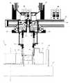
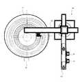
図1は本実施形態の自動溶接システムの平面図であり、図2は本実施形態の自動溶接システムの側面図(一部、断面図を含む)である。本実施形態の自動溶接システムは、溶接対象ワーク1(接合前の内輪2、静翼リング3、外輪4が内包状態で配置されたもの)を載置した状態で回転する回転テーブル11と、略クロス状に配置される2本のアーム51,52と回動軸となるコラム53を有するベース装置50と、内輪2と静翼リング3とを溶接する溶接トーチ21と、静翼リング3と外輪4とを溶接する溶接トーチ31と、溶接トーチ21に溶接ワイヤを送給するワイヤ送給装置22と、溶接トーチ31に溶接ワイヤを送給するワイヤ送給装置32と、コイル状の溶接ワイヤが設置されワイヤ送給装置22に溶接ワイヤを供給する溶接ワイヤ供給装置23と、コイル状の溶接ワイヤが設置されワイヤ送給装置32に溶接ワイヤを供給する溶接ワイヤ供給装置33と、溶接トーチ21を回転テーブル11の径方向に移動する溶接トーチシフト装置24と、溶接トーチ31を回転テーブル11の径方向に移動する溶接トーチシフト装置34と、溶接トーチ21を上下に移動する溶接トーチ駆動装置25と、溶接トーチ31を上下に移動する溶接トーチ駆動装置35と、溶接トーチ21を介してワイヤに電力を付加する溶接電源装置26と、溶接トーチ31を介してワイヤに電力を付加する溶接電源装置36と、溶接対象ワークに予熱を与える電気炉17と、回転テーブル11の回転角度ごとに外輪4に設けられた検出基準位置を検出する位置検出センサ18と、入力端末19と、これらの装置を制御する制御装置40とを備える。~ Basic configuration ~
FIG. 1 is a plan view of the automatic welding system of the present embodiment, and FIG. 2 is a side view (partly including a cross-sectional view) of the automatic welding system of the present embodiment. The automatic welding system of the present embodiment includes a rotary table 11 that rotates in a state where a
回転テーブル11には回転テーブル11の回転角度および回転数を検出する回転数検出センサ12が設けられている。回転数検出センサ12は、回転角度を検出し、単位時間当たりの回転角度に基づき回転数を検出する。 The rotation table 11 is provided with a rotation
ベース装置50はコラム53を中心に回動可能であり、溶接時にはアーム51が回転テーブル11上に位置するように、位置検出時にはアーム52が回転テーブル11上に位置するように制御される。アーム51の側面にはレール54が設けられ、溶接トーチシフト装置24,34により溶接ワイヤ供給装置23,33がレール上を移動することで、溶接トーチ21,31は回転テーブル11の径方向に移動する。アーム52には位置検出センサ18が固定される。 The
〜基本動作〜
自動溶接システムの基本動作について説明する。図3は、内輪2と静翼リング3との溶接箇所(第1溶接位置)である開先形状および静翼リング3と外輪4との溶接箇所(第2溶接位置)である開先形状を示す断面図である。この開先形状は、ルートギャップ、開先角度、開先深さにより設計段階で決められている。~basic action~
The basic operation of the automatic welding system will be described. FIG. 3 shows a groove shape that is a welded portion (first welding position) between the
第1溶接位置における溶接について説明する。溶接トーチ21を径方向に移動するとともに、上下方向にも移動する。上下方向の位置は、各パス(各層)のビード高およびアーク長に基づき設定される。径方向の位置は、開先角度に基づき各層毎に設定される。 The welding at the first welding position will be described. While moving the
コイル状の溶接ワイヤはワイヤ供給装置23に設置され、ワイヤ供給装置23からワイヤ送給装置22に供給され、ワイヤ送給装置22を介して所定の送給速度で溶接トーチ21を通過する。このとき、溶接電源装置26から溶接トーチ21を介して溶接ワイヤに電力を付加すると、アーク放電により溶接ワイヤは溶融し、所定のビード断面が形成される。 The coiled welding wire is installed in the
この状態で回転テーブル11が回転すると、周方向に連続するビードが形成され、1層目(1パス目)の溶接が完了する。その後、2層目の溶接に適した位置に溶接トーチ21を移動し、2層目(2パス目)の溶接を行なう。このように複数層の溶接を繰り返して開先深さまで埋めることにより、内輪2と静翼リング3とを接合する。 When the
第2溶接位置においても、第1溶接位置での溶接と連動して同様な溶接をおこない、静翼リング3と外輪4とを接合する。 At the second welding position, similar welding is performed in conjunction with the welding at the first welding position, and the
〜制御装置〜
図4は、制御装置40の機能ブロック図である。制御装置40は、演算処理機能41と記憶部42と駆動系制御機能43と電源制御機能44とを有する。~Control device~
FIG. 4 is a functional block diagram of the
演算処理機能41は、回転数検出センサ12や位置検出センサ18や入力端末19からの入力情報や記憶部42に記憶されている開先形状などの情報に基づき演算処理を行う。 The arithmetic processing function 41 performs arithmetic processing based on input information from the rotation
駆動系制御機能43は、演算処理機能41の演算処理結果に基づき、ワイヤ送給装置22,32や溶接ワイヤ供給装置23,33や溶接トーチシフト装置24,34や溶接トーチ駆動装置25,35の駆動や回転テーブル11の駆動(回転数)を制御する。溶接トーチの径方向位置制御は、駆動系制御機能43の一機能である。 The drive system control function 43 is based on the calculation processing result of the calculation processing function 41 and includes the
電源制御機能44は、演算処理機能41の演算処理結果に基づき、溶接電源装置26,36を制御することで、アーク長やワイヤ送給速度を制御する。 The power supply control function 44 controls the arc power and the wire feed speed by controlling the welding
制御装置40は更に特徴的構成として、溶接ビード断面均一維持制御機能45と内外調整機能46とを有している(後述)。 The
〜特徴的動作〜
自動溶接システムの特徴的な動作について説明する。~ Characteristic action ~
A characteristic operation of the automatic welding system will be described.
まず、予め、内輪2,静翼リング3,外輪4の形状、第1溶接位置の開先形状、第2溶接位置の開先形状や溶接ワイヤに係る情報を入力端末19を介して制御装置40の記憶部42に記憶する。演算処理機能41は、これらの情報に基づいて、各層毎のトーチ基準位置(図3参照)を演算する。 First, the
溶接対象ワーク1(接合前の内輪2、静翼リング3、外輪4が内包状態で配置されたもの)を回転テーブル11に載置する。このとき、従来技術では必須であった芯出し作業を省略する。 The
アーム52が回転テーブル11上に位置するようにベース装置50を回動制御する。図5は位置検出時の自動溶接システムの状態図(平面図)であり、図6はその詳細図(断面図)である。検出基準位置は外輪4の内側面に設けられている。位置検出センサ18はアーム52に固定されており、位置検出センサ18と検出基準位置との距離を検出することで、回転テーブル中心と検出基準位置との距離R0を検出する。 The
この状態で、回転テーブル11を一回転させ、回転数検出センサ12により回転角度を検出しながら、回転角度0〜360°に対応する距離R0(θ)を検出し、位置検出情報を記憶部42に記憶する。演算処理機能41は、開先形状(図3参照)等に基づき第1溶接位置における距離R1i(θ)および第1溶接位置における距離R2i(θ)を演算する。iは層番号を示す。つまり各層毎に距離R1(θ),距離R2(θ)を演算する。図7は、任意の層における位置検出情報を示す図である。 In this state, the rotation table 11 is rotated once, and the distance R0 (θ) corresponding to the
位置検出終了後、アーム51が回転テーブル11上に位置するようにベース装置50を回動制御する(図1参照)。溶接トーチ21,31を径方向および上下方向に移動し、トーチ基準位置に配置する。電気炉17は溶接対象ワーク1に予熱を与える。溶接準備が完了すると回転テーブル11を回転させ溶接を開始する。 After the position detection is completed, the
駆動系制御機能43は距離R1(θ)に基づき溶接トーチ21を径方向に移動し、距離R2(θ)に基づき溶接トーチ31を径方向に移動する。これにより、溶接トーチ21は常に第1溶接位置に維持され、溶接トーチ31は常に第2溶接位置に維持される。 The drive system control function 43 moves the
回転テーブル11が一回転すると、1層目の溶接が完了し、2層目の溶接を開始する。 When the
〜効果〜
自動溶接システムの位置検出に係る効果について説明する。~effect~
An effect related to position detection of the automatic welding system will be described.
上記構成により、本実施形態の自動溶接システムは従来技術では必須であった芯出し作業を省略できる。これにより、作業時間短縮を図ることができる。 With the above-described configuration, the automatic welding system of the present embodiment can omit the centering work that was essential in the prior art. Thereby, work time can be shortened.
自動溶接システムの芯出し不要に係る更なる効果について説明する。 The further effect which concerns on the centering unnecessary of an automatic welding system is demonstrated.
芯出し作業を伴う従来技術では、精度よく芯出しを行なったとしても、溶接対象ワーク1の成型精度が劣ると、溶接位置がずれるため溶接品質が劣る。 In the conventional technique involving the centering operation, even if the centering is performed with high accuracy, if the molding accuracy of the
本実施形態の自動溶接システムは、位置検出を行なうため、溶接対象ワーク1の成型精度に依らず、良好な溶接品質を維持できる。 Since the automatic welding system of this embodiment performs position detection, it can maintain good welding quality regardless of the molding accuracy of the
芯出し作業を伴う従来技術では、溶接対象ワーク1の平面形状は真円に限定される。 In the prior art involving the centering operation, the planar shape of the
本実施形態の自動溶接システムは、位置検出を行なうため、溶接対象ワーク1の平面形状は真円に限定されず、例えば、楕円や長円等にも適用できる。 Since the automatic welding system of this embodiment performs position detection, the planar shape of the
自動溶接システムの複数同時溶接に係る効果について説明する。 The effect concerning the multiple simultaneous welding of the automatic welding system will be described.
従来技術では、1つの溶接装置により第1溶接位置における溶接を行い、溶接完了後、第2溶接位置における溶接を行うことが一般的である。 In the prior art, it is common to perform welding at the first welding position with one welding device, and after the completion of welding, welding at the second welding position.
本実施形態の自動溶接システムは、第1溶接位置における溶接と第2溶接位置における溶接を同時に行うため、更なる作業時間短縮を図ることができる。 Since the automatic welding system of this embodiment performs welding in the 1st welding position and welding in the 2nd welding position simultaneously, it can aim at the further work time reduction.
第1溶接位置における溶接を行った後に第2溶接位置における溶接を行う従来技術では、第2溶接位置における溶接時には、第1溶接位置では放熱が開始しているため、第1溶接位置と第2溶接位置の間で、溶接歪による変形が生じるおそれがある。 In the prior art in which welding at the second welding position is performed after welding at the first welding position, since heat radiation starts at the first welding position at the time of welding at the second welding position, There is a risk of deformation due to welding distortion between welding positions.
本実施形態の自動溶接システムは、第1溶接位置における溶接と第2溶接位置における溶接を同時に行うため、溶接歪による変形を軽減できる。 Since the automatic welding system of the present embodiment performs welding at the first welding position and welding at the second welding position at the same time, deformation due to welding distortion can be reduced.
〜芯出しをしないことによる課題〜
上述のように本実施形態の自動溶接システムは、芯出し不要に係る構成を特徴としている。しかし、回転テーブル11の中心と溶接対象ワーク1の中心とが一致しない場合、下記のような新たな課題が生じる。-Problems caused by not centering-
As described above, the automatic welding system of the present embodiment is characterized by a configuration that does not require centering. However, when the center of the rotary table 11 and the center of the
従来技術のように、回転テーブル11の中心と溶接対象ワーク1の中心とが一致する場合、回転テーブル1の中心から溶接位置までの距離は一定(溶接対象ワーク1の半径)であり、溶接ワイヤの送給速度一定および回転テーブルの回転数一定であれば、1パスにおける溶接ビード断面は均一となる。 When the center of the
一方、回転テーブル11の中心と溶接対象ワーク1の中心とが一致しない場合、回転テーブルの中心から溶接位置までの距離は従来技術に比べ長くなったり短くなったりするため(図7参照)、溶接ワイヤの送給速度一定および回転テーブルの回転数一定であると、1パスにおける溶接ビード断面は不均一となる。すなわち、肉盛過剰部と肉盛不足部が生じる。 On the other hand, when the center of the rotary table 11 and the center of the
上記課題について詳細に説明する。図8は、各諸元を説明する図である。溶接対象ワーク1の内径をD1(m)とし、外径をD2(m)とする。回転テーブル中心と第1溶接位置との距離をR1(m)とし、回転テーブル中心と第2溶接位置との距離をR2(m)とする。回転テーブル11の基準位置からの変位を回転角度θ(deg)とし、回転テーブル11の回転数をn(rpm)とする。なお、dθ/dt=2πnの関係がある。また、溶接ワイヤ送給装置22の溶接ワイヤ送給速度をWS1(m/min)とし、このワイヤの断面積をWA1(m2)とする。溶接ワイヤ送給装置32の溶接ワイヤ送給速度をWS2(m/min)とし、このワイヤの断面積をWA2(m2)とする。一方、第1溶接位置におけるビード幅をBW1とし、ビード高をBH1とする。第2溶接位置におけるビード幅をBW2とし、ビード高をBH2とする。 The above problem will be described in detail. FIG. 8 is a diagram for explaining each item. The inner diameter of the
ここで、単位時間当たりの溶接ワイヤ供給量とビード体積の関係は以下のように表される。
第1溶接位置において
WS1×WA1=BW1×BH1×2π×R1×n(m3/min)
第2溶接位置において
WS2×WA2=BW2×BH2×2π×R2×n(m3/min)
第1溶接位置の関係式を変形すると、ビード断面積は以下のように表される。
BW1×BH1=(WS1×WA1/2πn)×(1/R1)(m2)
すなわち、WS1,WA1,nが一定の条件の下では、ビード断面積はR1に反比例する。一方、R1(θ)は図7のように、回転角度θに依り変動する。従って、R1が長くなるとビード断面積は小さくなり、R1が短くなるとビード断面積は大きくなる。Here, the relationship between the welding wire supply amount per unit time and the bead volume is expressed as follows.
WS1 × WA1 = BW1 × BH1 × 2π × R1 × n (m3 / min) at the first welding position
WS2 × WA2 = BW2 × BH2 × 2π × R2 × n (m3 / min) at the second welding position
When the relational expression of the first welding position is modified, the bead cross-sectional area is expressed as follows.
BW1 × BH1 = (WS1 × WA1 / 2πn) × (1 / R1) (m2)
That is, under the condition where WS1, WA1, n are constant, the bead cross-sectional area is inversely proportional to R1. On the other hand, R1 (θ) varies depending on the rotation angle θ as shown in FIG. Therefore, the bead cross-sectional area decreases as R1 increases, and the bead cross-sectional area increases as R1 decreases.
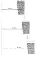
図9は、上記課題を説明する概念図である。従来技術と同様に、R1=D1であれば、所望の溶接ビード断面が得られる。しかし、R1>D1である場合は、肉盛不足になる。一方、R1<D1である場合は、肉盛過剰になる。溶接ビード断面が不均一であると、溶接品質が低下する。複数層の溶接を繰返すたび、溶接品質は更に低下する。 FIG. 9 is a conceptual diagram illustrating the above problem. Similar to the prior art, if R1 = D1, a desired weld bead cross section is obtained. However, when R1> D1, the overlay is insufficient. On the other hand, when R1 <D1, the overlay is excessive. If the cross section of the weld bead is not uniform, the weld quality is deteriorated. Each time the welding of multiple layers is repeated, the welding quality further decreases.
第2溶接位置においても同様な課題が生じる。 A similar problem occurs at the second welding position.
〜溶接ビード断面均一維持制御〜
制御装置40は更に特徴的構成として、溶接ビード断面均一維持制御機能45を有している(図4参照)。溶接ビード断面均一維持制御機能45について詳しく説明する。~ Weld bead cross-section uniform maintenance control ~
The
第1溶接位置の関係式を更に変形すると、ワイヤ送給速度/テーブル回転数は以下のように表される。
WS1×/n=(2π×BW1×BH1/WA1)×R1(m)
すなわち、WS1×/nがR1に比例する場合、溶接ビード断面均一となる。When the relational expression of the first welding position is further modified, the wire feed speed / table rotation speed is expressed as follows.
WS1 × / n = (2π × BW1 × BH1 / WA1) × R1 (m)
That is, when WS1 × / n is proportional to R1, the weld bead cross section is uniform.
溶接ビード断面均一維持制御機能45は、記憶部42から位置検出情報を入力し、演算処理機能41にR1(θ)に対応するWS1(θ)およびn(θ)を演算させる。さらに、WS2×/nがR2に比例するように、演算処理機能41にR2(θ)に対応するWS2(θ)を演算させる。 The weld bead cross-section uniform maintenance control function 45 inputs position detection information from the storage unit 42 and causes the calculation processing function 41 to calculate WS1 (θ) and n (θ) corresponding to R1 (θ). Further, the calculation processing function 41 calculates WS2 (θ) corresponding to R2 (θ) so that WS2 × / n is proportional to R2.
溶接ビード断面均一維持制御機能45は、演算処理結果に基づき、駆動系制御機能43に回転テーブル11の回転数nを制御させるとともに、電源制御機能44にワイヤ送給速度WS1,WS2を制御させる。 The weld bead cross-section uniform maintenance control function 45 causes the drive system control function 43 to control the rotation speed n of the
なお、ワイヤ送給速度WS1,WS2を一定に制御し、テーブル回転数nがR1,R2に反比例するように、テーブル回転数nを制御してもよい。図10は、テーブル回転数情報を示す図である。駆動系制御機能43はテーブル回転数情報に基づき、回転角度ごとにテーブル回転数を制御する。 The table rotation speed n may be controlled so that the wire feed speeds WS1 and WS2 are controlled to be constant and the table rotation speed n is inversely proportional to R1 and R2. FIG. 10 is a diagram showing table rotation speed information. The drive system control function 43 controls the table rotation speed for each rotation angle based on the table rotation speed information.
また、テーブル回転数nを一定に制御し、ワイヤ送給速度WS1がR1に比例し、かつ、ワイヤ送給速度WS2がR2に比例するように、ワイヤ送給速度WS1,WS2を制御してもよい。図11は、ワイヤ送給速度情報を示す図である。電源制御機能44はワイヤ送給速度情報に基づき、回転角度ごとにワイヤ送給速度を制御する。 Further, even if the table rotation speed n is controlled to be constant, the wire feed speeds WS1 and WS2 are controlled so that the wire feed speed WS1 is proportional to R1 and the wire feed speed WS2 is proportional to R2. Good. FIG. 11 is a diagram showing wire feed speed information. The power control function 44 controls the wire feed speed for each rotation angle based on the wire feed speed information.
溶接ビード断面均一維持制御機能45が作動することにより、芯出し作業を省略しても、溶接ビード断面を均一に維持できる。これにより溶接品質を維持できる。 By operating the weld bead cross-section uniform maintenance control function 45, the weld bead cross-section can be maintained uniformly even if the centering operation is omitted. Thereby, welding quality can be maintained.
〜内外間における課題〜
上述のように本実施形態の自動溶接システムは、複数同時溶接に係る構成を特徴としている。しかし、内側にある第1溶接位置における溶接長は、外側にある第2溶接位置における溶接長に比べて、短くなる。仮に、ワイヤ送給速度WS1,WS2が同一、ワイヤの断面積をWA1,WA2が同一の条件の下では、第1溶接位置では第2溶接位置に比べて肉盛過剰となり、第2溶接位置では第1溶接位置に比べて肉盛不足となる。従って、内外間において肉盛量を調整する必要がある。-Issues between inside and outside-
As described above, the automatic welding system of the present embodiment is characterized by the configuration related to the multiple simultaneous welding. However, the welding length at the first welding position on the inner side is shorter than the welding length at the second welding position on the outer side. Assuming that the wire feed speeds WS1 and WS2 are the same and the cross-sectional areas of the wires WA1 and WA2 are the same, the first welding position is overfilled compared to the second welding position, and at the second welding position. The overlay is insufficient compared to the first welding position. Therefore, it is necessary to adjust the build-up amount between the inside and outside.
電源制御機能44は、ワイヤ送給速度WS1とWS2を独立に制御できる。たとえば、D1/D2=WS1/WS2を満たすようにワイヤ送給速度を制御することで、上記内外間における課題を解決できる。 The power control function 44 can independently control the wire feed speeds WS1 and WS2. For example, by controlling the wire feeding speed so as to satisfy D1 / D2 = WS1 / WS2, the above-described problem between the inside and outside can be solved.
しかし、ワイヤ送給速度の制御だけでは対応できない場合もある。たとえば、電流値を大きくすればワイヤ送給速度を速くすることができるが、溶接電源装置26,36の電力供給能力に制限され電流値を大きくできない場合もある。 However, there are cases where it is not possible to cope only with control of the wire feed speed. For example, if the current value is increased, the wire feeding speed can be increased. However, the current value may not be increased due to the power supply capability of the welding
〜内外調整〜
制御装置40は更に特徴的構成として、内外調整機能46を有している(図4参照)。内外調整機能46について詳しく説明する。-Inside / outside adjustment-
The
上記〜基本動作〜および〜動作〜において述べたように、演算処理機能41は溶接開始前に開先形状等の情報に基づいて各層毎のトーチ基準位置を演算する。このとき、基準となるワイヤ送給速度も演算する。 As described in the above-mentioned basic operations and operations, the calculation processing function 41 calculates the torch reference position for each layer based on information such as the groove shape before starting welding. At this time, the reference wire feed speed is also calculated.
内外調整機能46は、ワイヤ送給速度の制御のみで内外間の調整ができるかを判断し、調整可能であると判断すると、次のステップに進み、自動溶接システムは溶接を開始する。 The inside / outside adjustment function 46 determines whether or not the adjustment between the inside and outside can be performed only by controlling the wire feed speed.
一方、調整不可能であると判断すると、入力端末19のモニタ部に調整不可能である旨および、推奨する溶接ワイヤの断面積(またはワイヤ径)、ワイヤ材質を表示する。 On the other hand, if it is determined that the adjustment is impossible, the monitor unit of the
第1溶接位置では第2溶接位置に比べて肉盛過剰となりやすいため、内外調整機能46は、ワイヤ断面積WA1<WA2となるような溶接ワイヤを選定する。また、電流値同一の条件の下ではワイヤ断面積が小さくなるとワイヤ送給速度が速くなる。 Since the first welding position is likely to be overfilled compared to the second welding position, the inside / outside adjustment function 46 selects a welding wire that satisfies the wire cross-sectional area WA1 <WA2. Also, under the same current value condition, the wire feeding speed increases as the wire cross-sectional area decreases.
また、耐熱材やSUS鋼の溶接ワイヤは、一般鋼に比べてより多くの電力を必要とする。つまり、電流値同一の条件の下ではワイヤ送給速度が遅くなる。 In addition, heat-resistant materials and SUS steel welding wires require more electric power than general steel. That is, the wire feed speed is slow under the same current value condition.
モニタ部の表示に基づき、ワイヤ供給装置23またはワイヤ供給装置33または両方に新しい溶接ワイヤを設置するとともに、新しい溶接ワイヤに係る情報(断面積、径、材質)を入力端末19を介して入力する。 Based on the display on the monitor unit, a new welding wire is installed in the
内外調整機能46は新たな情報に基づいて再度内外間の調整ができるかを判断し、調整可能であると判断すると、自動溶接システムは溶接を開始する。 The internal / external adjustment function 46 determines again whether the internal / external adjustment can be performed based on the new information. If the internal / external adjustment function 46 determines that the adjustment is possible, the automatic welding system starts welding.
内外調整機能46が作動することにより、ワイヤ送給速度の制御のみで内外間の調整が対応できない場合でも、第1溶接位置にて肉盛過剰となることなく、第2溶接位置にて肉盛不足となることなく、溶接できる。 By operating the inside / outside adjustment function 46, even if the adjustment between the inside and outside cannot be accommodated only by controlling the wire feed speed, the overlaying at the second welding position is not performed at the first welding position. It can be welded without running out.
〜変形例〜
本発明は、本実施形態に限定されず、種々の変形が可能である。いくつかの変形例を説明する。~ Modification ~
The present invention is not limited to this embodiment, and various modifications are possible. Several modifications will be described.
(1)本実施形態では、芯出し不要に係る特徴と、複数同時溶接に係る特徴について説明したが、どちらか一方の特徴を有するものでもよい。図12は第1変形例に係る構成を示す図であり、芯出し不要に係る特徴のみを有する。 (1) In this embodiment, although the feature which concerns on centering unnecessary and the feature which concerns on multiple simultaneous welding was demonstrated, it may have either one of the features. FIG. 12 is a diagram showing a configuration according to the first modification example, and has only a feature that does not require centering.
すなわち、第1変形例の自動溶接システムは、回転テーブル11と、回転数検出センサ12と、2本のアーム51,52とコラム53を有するベース装置50と、溶接トーチ21と、ワイヤ送給装置22と、溶接ワイヤ供給装置23と、溶接トーチシフト装置24と、溶接トーチ駆動装置25と、溶接電源装置26と、溶接対象ワークに予熱を与える電気炉17と、位置検出センサ18と、入力端末19と、これらの装置を制御する制御装置40とを備える(一部図示省略、図1参照)。 That is, the automatic welding system of the first modified example includes a rotary table 11, a rotation
第1変形例に係る自動溶接システムの動作について説明する。 The operation of the automatic welding system according to the first modification will be described.
まず、予め、開先形状等に係る情報を記憶する。演算処理機能41は、これらの情報に基づいて、各層毎のトーチ基準位置や基準供給電力等を演算する。 First, information related to the groove shape and the like is stored in advance. The calculation processing function 41 calculates the torch reference position, the reference supply power, etc. for each layer based on these pieces of information.
溶接対象ワーク1を回転テーブル11に載置する。回転テーブル11を一回転させ、位置検出センサ18により、回転角度0〜360°に対応する距離R0(θ)を検出し、第1溶接位置における距離R1(θ)および第1溶接位置における距離R2(θ)を演算する。 The
位置検出終了後、溶接トーチ21を径方向および上下方向に移動し、第1溶接位置におけるトーチ基準位置に配置する。回転テーブル11を回転させ、距離R1(θ)に基づいた径方向位置制御および溶接ビード断面均一維持制御をおこないながら溶接する。 After the position detection is completed, the
回転テーブル11が一回転すると、1層目の溶接が完了し、2層目の溶接を開始する。このように複数層の溶接を繰り返して開先深さまで埋まることにより、内輪2と静翼リング3とを接合する。 When the
第1溶接位置における溶接完了後、溶接トーチ21を径方向および上下方向に移動し、第2溶接位置におけるトーチ基準位置に配置する。回転テーブル11を回転させ、距離R2(θ)に基づいた径方向位置制御および溶接ビード断面均一維持制御をおこないながら溶接する。 After completion of welding at the first welding position, the
回転テーブル11が一回転すると、1層目の溶接が完了し、2層目の溶接を開始する。このように複数層の溶接を繰り返して開先深さまで埋まることにより、静翼リング3と外輪4とを接合する。 When the
芯出し作業を省略することにより、作業時間短縮を図ることができる。また、芯出し作業を省略しても、溶接ビード断面を均一に維持でき、溶接品質を維持できる。 By omitting the centering operation, the operation time can be shortened. Even if the centering operation is omitted, the weld bead cross section can be maintained uniformly, and the welding quality can be maintained.
(2)本実施形態では、ベース装置50は回動可能であり、自動溶接システムは位置検出後、溶接を開始したが、位置検出と溶接を同時におこなう構成でも良い。図13は第2変形例に係る構成を示す図である。 (2) In the present embodiment, the
第2変形例のベース装置50には、アーム51とアーム55が固定されている。アーム51の側面にはレール54が設けられ、溶接トーチシフト装置24,34により溶接ワイヤ供給装置23,33がレール上を移動することで、溶接トーチ21,31は回転テーブル11の径方向に移動する。アーム55には位置検出センサ18が固定される。位置検出センサ18は、回転テーブル11の回転角度ごとに外輪4に設けられた検出基準位置を検出する。 An
このとき、位置検出センサ18が第1溶接位置および第2溶接位置に対して位相90°前の検出基準位置を検出できるように、位置検出センサ18およびアーム55は設置されている。 At this time, the
第2変形例に係る自動溶接システムの動作について説明する。 The operation of the automatic welding system according to the second modification will be described.
まず、予め、開先形状等に係る情報を記憶する。演算処理機能41は、これらの情報に基づいて、各層毎のトーチ基準位置や基準供給電力等を演算する。 First, information related to the groove shape and the like is stored in advance. The calculation processing function 41 calculates the torch reference position, the reference supply power, etc. for each layer based on these pieces of information.
溶接対象ワーク1を回転テーブル11に載置する。回転テーブル11を回転させ、位置検出センサ18により、回転角度0〜360°に対応する距離R0(θ)を検出し、第1溶接位置における距離R1(θ)および第2溶接位置における距離R2(θ)を演算する。 The
これと同時に、溶接トーチ21,31を径方向および上下方向に移動し、第1溶接位置,第2溶接位置におけるトーチ基準位置に配置する。回転テーブル11を位相90°回転させ、距離R1(θ),距離R2(θ)に基づいた径方向位置制御および溶接ビード断面均一維持制御をおこないながら溶接を開始する。 At the same time, the welding torches 21 and 31 are moved in the radial direction and the vertical direction, and are arranged at the torch reference positions at the first welding position and the second welding position. The
回転テーブル11が一回転すると、1層目の溶接が完了し、2層目の溶接を開始する。2パス目(2層目)以降において、再度、位置検出を行なってもよい。 When the
第2変形例に係る自動溶接システムでは、本実施形態で述べた効果と同じ効果が得られる。 In the automatic welding system according to the second modification, the same effect as that described in the present embodiment can be obtained.
さらに、本実施形態において、位置検出後、溶接を開始するのに対し、第2変形例においては、位置検出と溶接を同時に行うため、更なる作業時間短縮を図ることができる。 Furthermore, in the present embodiment, welding is started after position detection, whereas in the second modified example, position detection and welding are performed at the same time, so that further work time reduction can be achieved.
また、本実施形態において、位置検出後、2パス目以降、最初の位置検出情報に基づいて距離R1(θ),距離R2(θ)を演算するのに対し、第2変形例においては、各パス毎の位置検出情報に基づいて距離R1(θ),距離R2(θ)を演算するため、より精度のよい制御ができる。このとき、位置検出と溶接を同時に行うため、作業時間が延長するといった問題は生じない。 In this embodiment, after the position detection, the distance R1 (θ) and the distance R2 (θ) are calculated based on the first position detection information after the second pass. Since the distance R1 (θ) and the distance R2 (θ) are calculated based on the position detection information for each path, more accurate control can be performed. At this time, since position detection and welding are performed simultaneously, there is no problem that the working time is extended.
1 溶接対象ワーク
2 内輪、
3 静翼リング
4 外輪
11 回転テーブル
12 回転数検出センサ
17 電気炉
18 位置検出センサ
19 入力端末
21 溶接トーチ
22 ワイヤ送給装置
23 溶接ワイヤ供給装置
24 溶接トーチシフト装置
25 溶接トーチ駆動装置
26 溶接電源装置
31 溶接トーチ
32 ワイヤ送給装置
33 溶接ワイヤ供給装置
34 溶接トーチシフト装置
35 溶接トーチ駆動装置
36 溶接電源装置
40 制御装置
41 演算処理機能
42 記憶部
43 駆動系制御機能
44 電源制御機能
45 溶接ビード断面均一維持制御機能
46 内外調整機能
50 ベース装置
51 アーム(溶接)
52 アーム(位置検出)
53 コラム
54 レール
55 アーム(位置検出)1 Workpiece to be welded 2 Inner ring,
3 Stator blade ring 4
52 Arm (position detection)
53
Claims (7)
Translated fromJapanese前記円筒状部材を載置した状態で回転する回転テーブルと、
前記回転テーブルが回転することにより、円筒状部材同士を周方向に溶接する溶接トーチを含む溶接装置と、
前記溶接トーチに溶接ワイヤを送給するワイヤ送給装置と、
前記溶接トーチを前記回転テーブルの径方向に移動する溶接トーチシフト装置と、
前記回転テーブルの回転角度ごとに前記円筒状部材の検出基準位置を検出する位置検出センサと、
前記位置検出センサによる検出基準位置に基づき、前記溶接トーチが適切な溶接位置にくるように、前記溶接トーチシフト装置を制御する溶接トーチシフト制御機能部を有する制御装置と
を備えることを特徴とする自動溶接システム。In an automatic welding system that welds two or more cylindrical members in an inclusive relationship to each other in the circumferential direction,
A rotating table that rotates with the cylindrical member mounted thereon;
A welding apparatus including a welding torch that welds cylindrical members in a circumferential direction by rotating the rotary table;
A wire feeding device for feeding a welding wire to the welding torch;
A welding torch shift device that moves the welding torch in the radial direction of the rotary table;
A position detection sensor for detecting a detection reference position of the cylindrical member for each rotation angle of the rotary table;
And a control device having a welding torch shift control function unit for controlling the welding torch shift device so that the welding torch comes to an appropriate welding position based on a reference position detected by the position detection sensor. Automatic welding system.
前記制御装置は、
前記回転テーブルの全回転角度で、1パスにおける溶接ビード断面が均一になるように、前記溶接位置と前記回転テーブルの中心との距離に基づき、前記回転テーブルの回転数と前記ワイヤ送給装置のワイヤ送給速度の少なくてもいずれかを制御する溶接ビード断面均一維持制御機能部
を有することを特徴とする自動溶接システム。The automatic welding system of claim 1,
The controller is
Based on the distance between the welding position and the center of the turntable so that the weld bead cross section in one pass is uniform at all rotation angles of the turntable, the rotation speed of the turntable and the wire feeding device An automatic welding system having a weld bead cross-section uniform maintenance control function for controlling at least one of the wire feed speeds.
前記溶接ビード断面均一維持制御機能部は、
前記ワイヤ送給装置のワイヤ送給速度/前記回転テーブルの回転数が、前記溶接位置と回転テーブル中心との距離に比例するように、前記回転テーブルの回転数および前記ワイヤ送給装置のワイヤ送給速度を制御する
ことを特徴とする自動溶接システム。The automatic welding system of claim 2,
The weld bead cross-section uniform maintenance control function unit,
The rotational speed of the rotary table and the wire feed speed of the wire feeder are adjusted so that the wire feed speed of the wire feeder / the rotational speed of the rotary table is proportional to the distance between the welding position and the center of the rotary table. An automatic welding system characterized by controlling the feeding speed.
前記溶接ビード断面均一維持制御機能部は、
前記ワイヤ送給装置のワイヤ送給速度を一定に制御し、
前記溶接位置と回転テーブル中心との距離に反比例するように、前記回転テーブルの回転数を制御する
ことを特徴とする自動溶接システム。The automatic welding system of claim 2,
The weld bead cross-section uniform maintenance control function unit,
The wire feeding speed of the wire feeding device is controlled to be constant,
The automatic welding system, wherein the number of rotations of the rotary table is controlled so as to be inversely proportional to the distance between the welding position and the center of the rotary table.
前記溶接ビード断面均一維持制御機能部は、
前記回転テーブルの回転数を一定に制御し、
前記溶接位置と回転テーブル中心との距離に比例するように、前記ワイヤ送給装置のワイヤ送給速度を制御する
ことを特徴とする自動溶接システム。The automatic welding system of claim 2,
The weld bead cross-section uniform maintenance control function unit,
The number of rotations of the rotary table is controlled to be constant,
An automatic welding system, wherein the wire feeding speed of the wire feeding device is controlled so as to be proportional to the distance between the welding position and the center of the rotary table.
前記溶接装置は、第1溶接位置および第2溶接位置を含む径方向の複数の溶接位置を同時溶接できるように、第1溶接位置を溶接する第1溶接トーチと、この第1溶接トーチの外側に配置され第2溶接位置を溶接する第2溶接トーチを含み、
前記制御装置は、
前記第1溶接位置および第2溶接位置においてそれぞれ所望の溶接ビード断面となるように、前記第1溶接トーチおよび第2溶接トーチに送給するワイヤのワイヤ径を選定する内外調整機能部
を有することを特徴とする自動溶接システム。The automatic welding system of claim 1,
The welding apparatus includes a first welding torch for welding the first welding position and an outer side of the first welding torch so that a plurality of radial welding positions including the first welding position and the second welding position can be welded simultaneously. A second welding torch for welding the second welding position,
The controller is
An inside / outside adjustment function unit for selecting a wire diameter of a wire to be fed to the first welding torch and the second welding torch so that a desired weld bead cross section is obtained at each of the first welding position and the second welding position; Automatic welding system characterized by
前記円筒状部材を回転テーブルに載置する載置ステップと、
前記回転テーブルの回転角度ごとに前記円筒状部材の検出基準位置を検出する位置検出ステップと、
この検出基準位置に基づき、溶接トーチが適切な溶接位置にくるように、前記溶接トーチを前記回転テーブルの径方向に移動する溶接トーチシフトステップと、
前記回転テーブルの全回転角度で、溶接ビード断面が均一になるように、前記溶接位置と前記回転テーブルの中心との距離に基づき、前記回転テーブルの回転数と前記溶接トーチに送給する溶接ワイヤのワイヤ送給速度の少なくてもいずれかを制御する溶接ビード断面均一制御ステップと、
前記溶接トーチが適切な溶接位置にあり、溶接ビード断面が均一になる状態で、前記回転テーブルが回転することにより、円筒状部材同士を周方向に溶接する溶接ステップと
を備えることを特徴とする自動溶接方法。In an automatic welding method of welding two or more cylindrical members in an enveloping relationship in the circumferential direction,
A mounting step of mounting the cylindrical member on a rotary table;
A position detection step of detecting a detection reference position of the cylindrical member for each rotation angle of the rotary table;
A welding torch shift step for moving the welding torch in the radial direction of the rotary table so that the welding torch comes to an appropriate welding position based on the detection reference position;
A welding wire fed to the number of rotations of the rotary table and the welding torch based on the distance between the welding position and the center of the rotary table so that the weld bead cross section becomes uniform at all rotation angles of the rotary table. A welding bead cross-sectional uniform control step for controlling at least one of the wire feeding speeds of
A welding step for welding the cylindrical members in the circumferential direction by rotating the rotary table in a state where the welding torch is at an appropriate welding position and a weld bead cross section is uniform. Automatic welding method.
Priority Applications (1)
| Application Number | Priority Date | Filing Date | Title |
|---|---|---|---|
| JP2011149154AJP5679923B2 (en) | 2011-07-05 | 2011-07-05 | Automatic welding system and automatic welding method |
Applications Claiming Priority (1)
| Application Number | Priority Date | Filing Date | Title |
|---|---|---|---|
| JP2011149154AJP5679923B2 (en) | 2011-07-05 | 2011-07-05 | Automatic welding system and automatic welding method |
Publications (2)
| Publication Number | Publication Date |
|---|---|
| JP2013013921Atrue JP2013013921A (en) | 2013-01-24 |
| JP5679923B2 JP5679923B2 (en) | 2015-03-04 |
Family
ID=47687125
Family Applications (1)
| Application Number | Title | Priority Date | Filing Date |
|---|---|---|---|
| JP2011149154AExpired - Fee RelatedJP5679923B2 (en) | 2011-07-05 | 2011-07-05 | Automatic welding system and automatic welding method |
Country Status (1)
| Country | Link |
|---|---|
| JP (1) | JP5679923B2 (en) |
Cited By (17)
| Publication number | Priority date | Publication date | Assignee | Title |
|---|---|---|---|---|
| CN103949749A (en)* | 2014-04-24 | 2014-07-30 | 成都焊研鑫锐机电设备制造有限公司 | Seam searching and positioning mechanism and high-precision tunnel welding equipment adopting same |
| CN104646802A (en)* | 2015-02-02 | 2015-05-27 | 晋州市水泵厂 | Internal welding device and welding method for submersible pump motor stator end ring |
| KR101573476B1 (en)* | 2015-04-01 | 2015-12-01 | 한국멕케이용재 주식회사 | Automatic overlay welding apparatus for diameter changable pipe |
| CN105364270A (en)* | 2015-12-15 | 2016-03-02 | 信质电机股份有限公司 | Three-station argon welding machine for motor stator |
| KR101614286B1 (en) | 2015-09-01 | 2016-04-21 | 한국멕케이용재 주식회사 | Automatic overlay welding apparatus for diameter changable pipe using universial joint |
| WO2016067890A1 (en)* | 2014-10-31 | 2016-05-06 | 三菱重工業株式会社 | Cylindrical-structure welding system and welding method |
| CN105583563A (en)* | 2016-03-04 | 2016-05-18 | 德阳市东汽实业开发有限责任公司 | Special steam turbine diaphragm blade grid assembling and welding tool |
| JP2016159301A (en)* | 2015-02-26 | 2016-09-05 | 三菱重工業株式会社 | Welding system, and welding method |
| CN105983810A (en)* | 2016-07-22 | 2016-10-05 | 昆山科森科技股份有限公司 | Welding fixture for minimally invasive scalpels |
| JP2018001270A (en)* | 2016-06-27 | 2018-01-11 | 株式会社ダイヘン | Arc-welding control method |
| JP2018061967A (en)* | 2016-10-12 | 2018-04-19 | 本田技研工業株式会社 | Welding method |
| CN108031948A (en)* | 2018-01-12 | 2018-05-15 | 中国航发哈尔滨东安发动机有限公司 | The vacuum brazing frock of rectifier assembly |
| CN108581361A (en)* | 2018-07-03 | 2018-09-28 | 浙江国际海运职业技术学院 | The automatic double-sided welding equipment of steel pipe and flange |
| CN111112912A (en)* | 2019-12-26 | 2020-05-08 | 常州机电职业技术学院 | Turbine shell rocker arm welding tool |
| CN114734175A (en)* | 2022-06-10 | 2022-07-12 | 河南广鹰机械制造有限公司 | Mixed-flow runner welding device for water turbine |
| CN114841959A (en)* | 2022-05-05 | 2022-08-02 | 广州东焊智能装备有限公司 | Automatic welding method and system based on computer vision |
| WO2022257232A1 (en)* | 2021-06-11 | 2022-12-15 | 南京涵铭置智能科技有限公司 | Turnover device for sheet metal processing and turnover positioning method therefor |
Citations (3)
| Publication number | Priority date | Publication date | Assignee | Title |
|---|---|---|---|---|
| JPS60221182A (en)* | 1984-04-18 | 1985-11-05 | Hitachi Ltd | Assembling and welding device of turbine diaphragm nozzle |
| JPS6281272A (en)* | 1985-09-20 | 1987-04-14 | アンサルド・コンポネンテイ・エツセ・ピ・ア | Method and apparatus for welding diaphragm of steam turbine |
| JPH0934523A (en)* | 1995-07-18 | 1997-02-07 | Kobe Steel Ltd | Control method for industrial robot |
- 2011
- 2011-07-05JPJP2011149154Apatent/JP5679923B2/ennot_activeExpired - Fee Related
Patent Citations (3)
| Publication number | Priority date | Publication date | Assignee | Title |
|---|---|---|---|---|
| JPS60221182A (en)* | 1984-04-18 | 1985-11-05 | Hitachi Ltd | Assembling and welding device of turbine diaphragm nozzle |
| JPS6281272A (en)* | 1985-09-20 | 1987-04-14 | アンサルド・コンポネンテイ・エツセ・ピ・ア | Method and apparatus for welding diaphragm of steam turbine |
| JPH0934523A (en)* | 1995-07-18 | 1997-02-07 | Kobe Steel Ltd | Control method for industrial robot |
Cited By (22)
| Publication number | Priority date | Publication date | Assignee | Title |
|---|---|---|---|---|
| CN103949749B (en)* | 2014-04-24 | 2016-04-06 | 成都焊研鑫锐机电设备制造有限公司 | The high accuracy tunnel welding equipment of Xun Weizhaofeng mechanism and application thereof |
| CN103949749A (en)* | 2014-04-24 | 2014-07-30 | 成都焊研鑫锐机电设备制造有限公司 | Seam searching and positioning mechanism and high-precision tunnel welding equipment adopting same |
| WO2016067890A1 (en)* | 2014-10-31 | 2016-05-06 | 三菱重工業株式会社 | Cylindrical-structure welding system and welding method |
| JP2016087632A (en)* | 2014-10-31 | 2016-05-23 | 三菱重工業株式会社 | Welding system and welding method for cylindrical structure |
| CN104646802A (en)* | 2015-02-02 | 2015-05-27 | 晋州市水泵厂 | Internal welding device and welding method for submersible pump motor stator end ring |
| CN104646802B (en)* | 2015-02-02 | 2016-11-02 | 晋州市水泵厂 | A kind of motor for submerged pump stator end ring interior welding device and welding method |
| JP2016159301A (en)* | 2015-02-26 | 2016-09-05 | 三菱重工業株式会社 | Welding system, and welding method |
| KR101573476B1 (en)* | 2015-04-01 | 2015-12-01 | 한국멕케이용재 주식회사 | Automatic overlay welding apparatus for diameter changable pipe |
| KR101614286B1 (en) | 2015-09-01 | 2016-04-21 | 한국멕케이용재 주식회사 | Automatic overlay welding apparatus for diameter changable pipe using universial joint |
| CN105364270A (en)* | 2015-12-15 | 2016-03-02 | 信质电机股份有限公司 | Three-station argon welding machine for motor stator |
| CN105583563A (en)* | 2016-03-04 | 2016-05-18 | 德阳市东汽实业开发有限责任公司 | Special steam turbine diaphragm blade grid assembling and welding tool |
| JP2018001270A (en)* | 2016-06-27 | 2018-01-11 | 株式会社ダイヘン | Arc-welding control method |
| CN105983810A (en)* | 2016-07-22 | 2016-10-05 | 昆山科森科技股份有限公司 | Welding fixture for minimally invasive scalpels |
| JP2018061967A (en)* | 2016-10-12 | 2018-04-19 | 本田技研工業株式会社 | Welding method |
| CN108031948A (en)* | 2018-01-12 | 2018-05-15 | 中国航发哈尔滨东安发动机有限公司 | The vacuum brazing frock of rectifier assembly |
| CN108581361A (en)* | 2018-07-03 | 2018-09-28 | 浙江国际海运职业技术学院 | The automatic double-sided welding equipment of steel pipe and flange |
| CN111112912A (en)* | 2019-12-26 | 2020-05-08 | 常州机电职业技术学院 | Turbine shell rocker arm welding tool |
| CN111112912B (en)* | 2019-12-26 | 2020-12-18 | 常州机电职业技术学院 | A kind of turbine shell rocker arm welding tool |
| WO2021128717A1 (en)* | 2019-12-26 | 2021-07-01 | 常州机电职业技术学院 | Welding fixture for turbine housing rocker arm |
| WO2022257232A1 (en)* | 2021-06-11 | 2022-12-15 | 南京涵铭置智能科技有限公司 | Turnover device for sheet metal processing and turnover positioning method therefor |
| CN114841959A (en)* | 2022-05-05 | 2022-08-02 | 广州东焊智能装备有限公司 | Automatic welding method and system based on computer vision |
| CN114734175A (en)* | 2022-06-10 | 2022-07-12 | 河南广鹰机械制造有限公司 | Mixed-flow runner welding device for water turbine |
Also Published As
| Publication number | Publication date |
|---|---|
| JP5679923B2 (en) | 2015-03-04 |
Similar Documents
| Publication | Publication Date | Title |
|---|---|---|
| JP5679923B2 (en) | Automatic welding system and automatic welding method | |
| JP6303673B2 (en) | Overlay welding method to mold surface | |
| US8436278B2 (en) | Method for joining two rotationally symmetrical metal parts by tungsten inert gas (TIG) welding, and a device for carrying out the method | |
| EP3181283A1 (en) | Systems and method for automated root pass welding | |
| JPH11254140A (en) | Method and apparatus for controlling welding robot | |
| JP2014525838A (en) | Forming method for hot forming of steel sheet for rotor blades to be manufactured by a wind turbine generator | |
| JP6964544B2 (en) | Manufacturing method of modeled object and modeled object | |
| EP3162490B1 (en) | Cylindrical-structure welding system and welding method | |
| JP6311933B2 (en) | Electrode connection mechanism of welding equipment | |
| CN108472772A (en) | Method for manufacturing the sheet material group being made of the sheet material being stacked and the equipment for implementing such method | |
| JP6705711B2 (en) | Spinning molding method | |
| JPH11267832A (en) | Columnar material girth welding method and device | |
| KR100823551B1 (en) | Pipe automatic welding device and its welding method | |
| JP6686313B2 (en) | Welding equipment | |
| JP7381422B2 (en) | Manufacturing method of modeled object and modeled object | |
| JP2013094783A (en) | Processing method of workpiece | |
| JP5851694B2 (en) | Cylindrical weld forming method and welding apparatus | |
| CN111805057A (en) | Metal lamination molding method | |
| JP2023151889A (en) | Rotor manufacturing device | |
| JP2024007014A (en) | Welding equipment and welding method | |
| JPH01224167A (en) | Steel pipe welding equipment | |
| JPH0426948B2 (en) | ||
| JP2002178157A (en) | Overlay welding method and overlay welding apparatus | |
| JP6400855B2 (en) | Welding method and welding apparatus | |
| JP6972250B1 (en) | Welding equipment and welding method |
Legal Events
| Date | Code | Title | Description |
|---|---|---|---|
| A621 | Written request for application examination | Free format text:JAPANESE INTERMEDIATE CODE: A621 Effective date:20130809 | |
| A977 | Report on retrieval | Free format text:JAPANESE INTERMEDIATE CODE: A971007 Effective date:20140409 | |
| A131 | Notification of reasons for refusal | Free format text:JAPANESE INTERMEDIATE CODE: A131 Effective date:20140520 | |
| A521 | Written amendment | Free format text:JAPANESE INTERMEDIATE CODE: A523 Effective date:20140722 | |
| RD02 | Notification of acceptance of power of attorney | Free format text:JAPANESE INTERMEDIATE CODE: A7422 Effective date:20140722 | |
| A711 | Notification of change in applicant | Free format text:JAPANESE INTERMEDIATE CODE: A712 Effective date:20140827 | |
| RD02 | Notification of acceptance of power of attorney | Free format text:JAPANESE INTERMEDIATE CODE: A7422 Effective date:20141001 | |
| TRDD | Decision of grant or rejection written | ||
| A01 | Written decision to grant a patent or to grant a registration (utility model) | Free format text:JAPANESE INTERMEDIATE CODE: A01 Effective date:20141224 | |
| A61 | First payment of annual fees (during grant procedure) | Free format text:JAPANESE INTERMEDIATE CODE: A61 Effective date:20150106 | |
| R150 | Certificate of patent or registration of utility model | Ref document number:5679923 Country of ref document:JP Free format text:JAPANESE INTERMEDIATE CODE: R150 | |
| R250 | Receipt of annual fees | Free format text:JAPANESE INTERMEDIATE CODE: R250 | |
| LAPS | Cancellation because of no payment of annual fees |