JP2013012445A - Planar lighting device - Google Patents
Planar lighting deviceDownload PDFInfo
- Publication number
- JP2013012445A JP2013012445AJP2011145892AJP2011145892AJP2013012445AJP 2013012445 AJP2013012445 AJP 2013012445AJP 2011145892 AJP2011145892 AJP 2011145892AJP 2011145892 AJP2011145892 AJP 2011145892AJP 2013012445 AJP2013012445 AJP 2013012445A
- Authority
- JP
- Japan
- Prior art keywords
- substrate
- case
- guide plate
- led
- light guide
- Prior art date
- Legal status (The legal status is an assumption and is not a legal conclusion. Google has not performed a legal analysis and makes no representation as to the accuracy of the status listed.)
- Pending
Links
- 239000000758substrateSubstances0.000claimsabstractdescription97
- 238000005286illuminationMethods0.000claimsdescription16
- 229910052751metalInorganic materials0.000claimsdescription9
- 239000002184metalSubstances0.000claimsdescription9
- 239000004020conductorSubstances0.000claimsdescription6
- 230000000149penetrating effectEffects0.000claimsdescription2
- 230000008602contractionEffects0.000abstractdescription2
- 230000005855radiationEffects0.000abstract1
- NJPPVKZQTLUDBO-UHFFFAOYSA-NnovaluronChemical compoundC1=C(Cl)C(OC(F)(F)C(OC(F)(F)F)F)=CC=C1NC(=O)NC(=O)C1=C(F)C=CC=C1FNJPPVKZQTLUDBO-UHFFFAOYSA-N0.000description14
- 230000017525heat dissipationEffects0.000description7
- RYGMFSIKBFXOCR-UHFFFAOYSA-NCopperChemical compound[Cu]RYGMFSIKBFXOCR-UHFFFAOYSA-N0.000description5
- 239000011889copper foilSubstances0.000description4
- 239000007769metal materialSubstances0.000description4
- 229910052782aluminiumInorganic materials0.000description3
- XAGFODPZIPBFFR-UHFFFAOYSA-NaluminiumChemical compound[Al]XAGFODPZIPBFFR-UHFFFAOYSA-N0.000description3
- 239000004973liquid crystal related substanceSubstances0.000description3
- 230000002093peripheral effectEffects0.000description3
- 230000000694effectsEffects0.000description2
- 239000000463materialSubstances0.000description2
- 229920005672polyolefin resinPolymers0.000description2
- 229920005990polystyrene resinPolymers0.000description2
- 229920005989resinPolymers0.000description2
- 239000011347resinSubstances0.000description2
- 229910001220stainless steelInorganic materials0.000description2
- 239000010935stainless steelSubstances0.000description2
- 229910052802copperInorganic materials0.000description1
- 239000010949copperSubstances0.000description1
- 238000010586diagramMethods0.000description1
- 238000009792diffusion processMethods0.000description1
- 239000003822epoxy resinSubstances0.000description1
- 238000009413insulationMethods0.000description1
- 239000000113methacrylic resinSubstances0.000description1
- 238000000465mouldingMethods0.000description1
- 230000003287optical effectEffects0.000description1
- 230000035515penetrationEffects0.000description1
- 229920005668polycarbonate resinPolymers0.000description1
- 239000004431polycarbonate resinSubstances0.000description1
- 229920000647polyepoxidePolymers0.000description1
- 229920001225polyester resinPolymers0.000description1
- 239000004645polyester resinSubstances0.000description1
Images


Landscapes
- Fastening Of Light Sources Or Lamp Holders (AREA)
- Arrangement Of Elements, Cooling, Sealing, Or The Like Of Lighting Devices (AREA)
- Planar Illumination Modules (AREA)
Abstract
Description
Translated fromJapanese本発明は、面状照明装置に関するものである。 The present invention relates to a planar illumination device.
近年の青色発光ダイオード(LED)の高性能化に伴い、LEDを光源に用いた面状照明装置が広く用いられるようになっている。面状照明装置は、発光面を構成する導光板と、導光板の側端面に対向して配置されるLEDと、LEDが実装される回路基板とで構成される、サイドライト型と呼ばれる面状照明装置が一般的である。 With the recent improvement in performance of blue light-emitting diodes (LEDs), planar lighting devices using LEDs as light sources have been widely used. A planar lighting device is a planar shape called a sidelight type, which is composed of a light guide plate that constitutes a light emitting surface, LEDs that are disposed to face side end surfaces of the light guide plate, and a circuit board on which the LEDs are mounted. A lighting device is common.
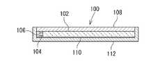
図4には、従来の、面状照明装置をバックライトとして備える液晶表示装置100の構造が概略的に示されている。この液晶表示装置100は、導光板102と、導光板の側端面に対向して配置される点状光源としてのLED104と、導光板102の側端面に対向して配置されLED104が実装される基板106と、導光板102の表面(光出射面)に配置されるLCD108と、導光板102の裏面に配置される反射シート110と、これらの各構成要素を収納するケース112とで構成されている。FIG. 4 schematically shows a structure of a conventional liquid
図4の例では、基板106は金属基板であり、ケース112も銅、アルミニウム等で構成されていることから、LED104から発生する熱は、基板106からケース112へと伝わり、ケース112の表面から外部へと放出されるものである。このように、LED104の放熱経路が確保されることで、LED104の温度上昇による発光効率の低下を防ぐことが可能となる(特許文献1参照)。 In the example of FIG. 4, the
しかしながら、従来の面状照明装置において、LEDからの発熱を逃がすための放熱経路を構成するべく採用された金属基板は、PCB、FPC等の一般的なプリント基板に比べて高コストとなることが指摘されている(特開2008−186780号公報の段落0007参照)。
本発明は、上記のような問題に鑑みなされたものであり、その目的とするところは、面状照明装置において、LEDの放熱性の確保とコストの低減との両立を図ることにある。However, in a conventional planar lighting device, a metal substrate adopted to constitute a heat dissipation path for releasing heat from the LED may be more expensive than a general printed circuit board such as PCB or FPC. It has been pointed out (see paragraph 0007 of JP 2008-186780 A).
This invention is made | formed in view of the above problems, and the place made into the objective is to aim at coexistence with ensuring of the heat dissipation of LED, and reduction of cost in a planar illuminating device.
(発明の態様)
以下の発明の態様は、本発明の構成を例示するものであり、本発明の多様な構成の理解を容易にするために、項別けして説明するものである。各項は、本発明の技術的範囲を限定するものではなく、発明を実施するための最良の形態を参酌しつつ、各項の構成要素の一部を置換し、削除し、又は、更に他の構成要素を付加したものについても、本願発明の技術的範囲に含まれ得るものである。(Aspect of the Invention)
The following aspects of the present invention exemplify the configuration of the present invention, and will be described separately for easy understanding of various configurations of the present invention. Each section does not limit the technical scope of the present invention, and some of the components of each section are replaced, deleted, or further while referring to the best mode for carrying out the invention. Those to which the above components are added can also be included in the technical scope of the present invention.
(1)導光板と、該導光板の側端面に対向して配置される点状光源と、該導光板の側端面に対向して配置され前記点状光源が実装される基板と、該基板を保持する熱伝導部材と、これらの各構成要素を収納するケースとを備え、前記熱伝導部材は前記ケースとの接触部を具備して、前記導光板の側端面と前記基板との間に介在しており、前記基板の前記点状光源が実装される実装面が、前記熱伝導部材と対向するようにして前記熱伝導部材に固定されている面状照明装置(請求項1)。(1) A light guide plate, a point light source disposed to face the side end surface of the light guide plate, a substrate disposed to face the side end surface of the light guide plate and mounted with the point light source, and the substrate A heat conductive member that holds the components, and a case that houses each of these components, the heat conductive member having a contact portion with the case, and between the side end surface of the light guide plate and the substrate. A planar illumination device that is interposed and fixed to the heat conducting member such that a mounting surface of the substrate on which the point light source is mounted faces the heat conducting member (Claim 1).
本項に記載の面状照明装置は、基板の点状光源が実装される実装面が、熱伝導部材と対向するようにして熱伝導部材に固定されていることにより、点状光源からの発熱は、効率的に熱伝導部材へと伝わる。熱伝導部材は、ケースとの接触部を具備していることから、点状光源から熱伝導部材に伝わった熱は、更に、接触部を介してケースへと伝わり、ケースの表面から外部へと放出される。なお、基板の実装面が、導光板の側端面と基板との間に介在する熱伝導部材に固定されることで、基板の実装面に実装される点状光源は、導光板の側端面に対向するようにして、位置決めされることとなる。In the planar illumination device described in this section, the mounting surface on which the point light source of the substrate is mounted is fixed to the heat conduction member so as to face the heat conduction member, so that heat is generated from the point light source. Is efficiently transmitted to the heat conducting member. Since the heat conducting member has a contact portion with the case, the heat transferred from the point light source to the heat conducting member is further transferred to the case through the contact portion, and from the surface of the case to the outside. Released. The point light source mounted on the mounting surface of the substrate is fixed to the side end surface of the light guide plate by fixing the mounting surface of the substrate to the heat conducting member interposed between the side end surface of the light guide plate and the substrate. Positioning is performed so as to face each other.
(2)上記(1)項において、前記熱伝導部材の接触部は、少なくとも前記基板の長手方向の全体に渡る長さを有している面状照明装置。
本項に記載の面状照明装置は、熱伝導部材の接触部は、少なくとも基板の長手方向の全体に渡る長さを有していることで、ケースに対する前記熱伝導部材の接触面積を十分に確保するものである。そして、熱伝導部材からケースへの熱伝導効率を高めるものである。(2) In the above item (1), the contact portion of the heat conducting member is a planar lighting device having a length over at least the entire length of the substrate.
In the planar lighting device described in this section, the contact portion of the heat conductive member has a length extending at least over the entire length of the substrate, so that the contact area of the heat conductive member with respect to the case is sufficiently large. It is to secure. And the heat-conduction efficiency from a heat conductive member to a case is improved.
(3)上記(1)(2)項において、前記ケースは、床部と該床部の端部から起立する壁部とを有し、前記熱伝導部材の接触部は、前記ケースの床部の床面に沿って摺動可能に載置され、前記熱伝導部材と前記ケースの壁部との間に、弾性部材が配置されている面状照明装置(請求項2)。
本項に記載の面状照明装置は、熱伝導部材の接触部が、ケースの床部の床面に沿って摺動可能に載置されていることにより、点状光源からの発熱を受けて、点状光源と対向する導光板やケース等に伸縮が生じても、その寸法変化を、熱伝導部材がケースに対して移動することで吸収するものである。又、熱伝導部材とケースの壁部との間に配置された、弾性部材の弾性力によって、上記寸法変化の有無に関わらず、点状光源と導光板との適切な位置関係を保持するものである。(3) In the above items (1) and (2), the case includes a floor portion and a wall portion standing from an end portion of the floor portion, and the contact portion of the heat conducting member is a floor portion of the case. A planar lighting device that is slidably mounted along the floor surface and in which an elastic member is disposed between the heat conducting member and the wall portion of the case (Claim 2).
In the planar lighting device described in this section, the contact portion of the heat conducting member is slidably placed along the floor surface of the floor portion of the case, thereby receiving heat from the point light source. Even if the light guide plate or the case facing the point light source expands or contracts, the dimensional change is absorbed by the heat conduction member moving with respect to the case. In addition, the elastic member disposed between the heat conducting member and the case wall retains an appropriate positional relationship between the point light source and the light guide plate regardless of the above-described dimensional change. It is.
(4)上記(1)から(3)項において、前記熱伝導部材は、前記接触部を構成する基部と、該基部から起立する基板保持部を備え、該基板保持部に前記基板が固定されている面状照明装置(請求項3)。
本項に記載の面状照明装置は、熱伝導部材の基部から起立する基板保持部の、導光板との対向面とは反対側の面に、基板が固定されることで、基板の実装面に実装される点状光源は、導光板の側端面に対向して配置されることとなる。そして、基板保持部に固定された基板に実装された点状光源からの発熱は、熱伝導部材の基板保持部から基部へと伝わり、更に、基部からケースの床部へと伝わるものである。(4) In the above items (1) to (3), the heat conducting member includes a base portion constituting the contact portion and a substrate holding portion standing up from the base portion, and the substrate is fixed to the substrate holding portion. A planar lighting device (Claim 3).
The planar lighting device described in this section is configured so that the substrate is fixed to the surface of the substrate holding unit that stands up from the base of the heat conducting member, on the side opposite to the surface facing the light guide plate. The point light source mounted on is disposed to face the side end face of the light guide plate. Then, heat generated from the point light source mounted on the substrate fixed to the substrate holding portion is transmitted from the substrate holding portion of the heat conducting member to the base portion, and further from the base portion to the floor portion of the case.
(5)上記(4)項において、前記基板保持部に、前記点状光源を貫通させる開口部が形成されている面状照明装置(請求項4)。
本項に記載の面状照明装置は、熱伝導部材の基板保持部に形成されている開口部を介して、基板の実装面に実装される点状光源が、導光板の側端面に対面するものである。この開口部は、点状光源の外形に倣った形状の開口が基板保持部に形成されたものであっても良く、又、基板保持部の端辺に一部が開放する切り欠きであっても良い。いずれにせよ、基板保持部は、開口部を設けることにより、基板保持部に点状光源の貫通路を確保した上で、点状光源の周囲の少なくとも二辺を取囲むように基板の実装面との接触面を形成することで、基板の実装面との必要な接触面積を確保するものである。(5) The planar illumination device according to (4), wherein an opening for penetrating the point light source is formed in the substrate holding part.
In the surface illumination device described in this section, the point light source mounted on the mounting surface of the substrate faces the side end surface of the light guide plate through the opening formed in the substrate holding portion of the heat conducting member. Is. The opening may be an opening having a shape following the outer shape of the point light source formed in the substrate holding portion, and is a notch that is partially opened at the edge of the substrate holding portion. Also good. In any case, the substrate holding portion is provided with an opening so that a through-hole for the point light source is secured in the substrate holding portion, and at least two sides around the point light source are surrounded. By forming the contact surface, the necessary contact area with the mounting surface of the substrate is ensured.
(6)上記(1)から(5)項において、前記熱伝導部材は、金属製である面状照明装置(請求項5)。
本項に記載の面状照明装置は、熱伝導部材が金属製であることにより、必要な熱伝導率を確保するものである。
(7)上記(1)から(6)項において、前記基板の導体パターンの幅は、前記点状光源の幅以上に形成されている面状照明装置(請求項6)。
本項に記載の面状照明装置は、基板の導体パターンを介して点状光源からの発熱を熱伝導部材へと伝える際に、基板の熱伝導に大きく寄与する領域(導体パターン)を広くすることで、基板から熱伝導部材への放熱経路を広げるものである。(6) In the above items (1) to (5), the heat conduction member is a planar illumination device made of metal (claim 5).
The planar illuminating device described in this section secures necessary heat conductivity because the heat conducting member is made of metal.
(7) The planar illumination device according to (1) to (6) above, wherein the width of the conductor pattern of the substrate is greater than the width of the point light source.
The planar illumination device described in this section widens a region (conductor pattern) that greatly contributes to the heat conduction of the substrate when the heat from the point light source is transmitted to the heat conducting member through the conductor pattern of the substrate. This widens the heat dissipation path from the substrate to the heat conducting member.
本発明はこのように構成したので、面状照明装置において、LEDの放熱性の確保とコストの低減との両立を図ることが可能となる。 Since this invention was comprised in this way, it becomes possible to aim at coexistence with ensuring of the heat dissipation of LED, and cost reduction in a planar illuminating device.
以下、本発明の実施の形態を図面に基づき説明する。
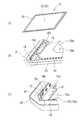
図1、図2に示されるように、本発明の実施の形態に係る面状照明装置10は、点状光源としてのLED12と、LED12が実装される基板14と、基板14を保持する支持部材16と、LED12を側端面(入光面)に配置し、入光面から入光した光を主平面(出射面)から出射させる導光板18と、支持部材16(LED12)および導光板18を収納するケース20と、基板14の実装面側とは反対側に配置されるクッション(弾性部材)22と、ケース20と対をなし、導光板18の出射面の外周部分を覆うカバー24とを備えている。Hereinafter, embodiments of the present invention will be described with reference to the drawings.
As shown in FIGS. 1 and 2, the
LED12は、本実施の形態では、いわゆる擬似白色LEDが用いられている。又、LED12を実装する基板14は、本実施の形態では、安価なPCBを短冊状に形成したものであり、導光板18の入光面に沿って配置されている。又、基板14の実装面には、図3に示されるように、銅箔パターン26がLED12の幅以上に形成され、それによって、可能な限り広い面積が確保されるように考慮されている。図3の例では、ランドおよび隣接するランドを結ぶ配線の幅を広く形成した銅箔パターン26が採用されている。なお、銅箔パターン26と支持部材16の間の少なくとも一部に、カバーレイ28を介在させることにより、必要な絶縁性を確保している。 In the present embodiment, a so-called pseudo white LED is used as the
支持部材16は、金属材料、好ましくは、伝熱性に優れ安価なアルミニウムが用いられることで、熱伝導部材を構成するものである。図示の例では、アルミ板を断面L字状に成形することで、ケース20と直接的に接触する接触部を構成する基部16aと、基部16aに直交するようにして基部16aから起立する基板保持部16bとを有している。又、図示の例では、基部16a及び基板保持部16bは、少なくとも基板の長手方向の全体に渡る長さを有している。又、基板保持部16bには、各LED12に対応した位置に貫通させる開口部16cが形成されている。図示の例では、開口部16cはLED12の外形に倣った矩形状の開口であるが、基板保持部16bの端辺に一部が開放する切り欠きであっても良い。そして、基板保持部16bの外側の面、すなわち、導光板18との対向面とは反対側の面に対して、基板14の実装面が対向するようにして、基板14は熱伝導性両面テープ(図示省略)を用いて固定されている。又、基板保持部16bの外側の面に基板14が固定された状態で、LED12は開口部16cを貫通し、LED12の発光面が基板保持部16bの内側の面、すなわち、導光板18との対向面から導光板18側に幾分突き出るように、基板保持部16bの肉厚が設定されている。従って、図2の例では、開口部16cを貫通したLED12は、導光板18の側端面に当接している。
更に、支持部材16は、基部16aから切り起こされ、基部16aと平行な面を構成する台座部16d(支持部材16の台座16d)を備えている。そして、支持部材16の台座部16dに、導光板18が載置されるものである。The
Further, the
導光板18は透明樹脂材料を成形してなる板状の導光体であり、矩形平板状に形成されている。そして、入光面から入射した光を出射面から面状に出射させるために、出射面と対向する面(支持部材16の台座部16d側の面)には、例えばドット状の光路変更手段が形成されている。導光板18の好適な透明樹脂材料には、メタクリル樹脂、ポリカーボネート樹脂、ポリスチレン樹脂、ポレオレフィン樹脂、非晶性ポリオレフィン樹脂、ポリエステル樹脂、ポリスチレン樹脂、透明フッ素樹脂、エポキシ樹脂等が含まれる。 The
ケース20は、金属材料(例えば、ステンレス)を用いて全体として無蓋箱状に形成された板金部品であり、低コストに製造することが可能である。このケース20は、床部20aと、床部の外周側から起立する壁部20bを有している。床部20aには、支持部材16の基部16aが(固定されずに)載置されている。従って、支持部材16は、ケース20の床部20aの床面に沿った所定幅の範囲が、摺動可能に配置されたものである。又、ケース20の床部20aの中央部に開口20cが形成され、かつ、開口20cに沿って切り起こされることで、床部20a(基部16d)と平行な面を構成する台座部20d(ケース20の台座部20d)が形成されている。ケース20の台座部20dは、支持部材16の台座部16dと同様に、導光板18が載置されるものであるが、その位置が固定されている点が、支持部材16の台座部16dと相違する。なお、ケース20の開口20cは、ケース20の軽量化を主目的として形成されたものであり、それに起因するケース20の強度低下を、台座部20によって補うことも可能となる。
なお、支持部材16の台座部16d、及び、ケース20の台座部20dは、導光板18の入光面とLED12の発光面とが対向するように、それらの高さが調整されている。The
Note that the height of the
クッション22は、図示の例では、直方体状に形成されたゴム等の弾性部材が、ケース20の壁部20bと基板14との間に配置されたものであるが、ケース20の壁部20bから基板14の方向へと向かう弾性力を付与するものであれば、ばねその他の機械的構造を有するものであっても良い。 In the illustrated example, the
カバー24は、金属材料(例えば、ステンレス)を用いて全体として無蓋箱状に形成された板金部材であり、低コストで製造することが可能である。そして、ケース20と組み合わさることで、上記各構成要素を収納するように、ケース20の各壁部20b(一般的には4辺)にそれぞれ対向する壁部24aと、各壁部24aの一端(図示上端)から内側に張り出し、全体として枠状に形成された庇部24bを有している。又、庇部24bに囲まれ、導光板18の出射面よりも一回り小さい大きさの開口部24cを有している。そして、この開口部24cから外部に照明光が出射するように構成されている。また、カバー24の庇部24bとケース20の床部20aとにより、支持部材16および導光板18の厚み方向(図示上下方向)の移動が規制される。
なお、カバー24の壁部24aは、ケース20の壁部20bの外周面をそれぞれ覆うように配置され、カバー24の壁部24aとケース20の壁部20bとは、例えば、ねじ等によって互いに固定されるものである。The
The
更に、本実施の形態では、導光板18の裏面(出射面と反対側の面)側に反射シート30が配置され、導光板18の出射面側に拡散シート32が配置されている。
又、本実施の形態は、導光板18の4つの側面に複数のLED12がそれぞれ配置(4辺配置)され、いずれの側面においても上記の構成が採用されているが、本発明は、かかる4辺配置に限定されるものでなく、例えば、1辺配置(1つの側面に配置)を採用する場合にも適用可能なものである。Further, in the present embodiment, the
In the present embodiment, a plurality of
さて、上記構成をなす、本発明の実施の形態によれば、次のような作用効果を得ることが可能となる。まず、本発明の実施の形態に係る面状照明装置10は、基板14のLED12が実装される実装面が、熱伝導部材を構成する支持部材16と対向するようにして、支持部材16に固定されていることにより、LED12からの発熱は、支持部材16に伝わる。熱伝導部材である支持部材16は、ケース20との接触部である基部16aを具備していることから、LED12から支持部材16に伝わった熱は、更に、基部16aを介してケース20へと伝わり、ケース20の表面から外部へと放出される。しかも、基板14の実装面が、導光板18の側端面と基板14との間に介在する支持部材16に固定されることで、基板14の実装面に実装されるLED12は、導光板18の側端面に対向するようにして、位置決めされることとなる。Now, according to the embodiment of the present invention configured as described above, the following operational effects can be obtained. First, the
又、支持部材16の基部16a及び基板保持部16bは、少なくとも基板14の長手方向の全体に渡る長さを有していることで、基板14及びケース20に対する支持部材16の接触面積を十分に確保し、支持部材16からケース20への熱伝導効率を高めることができる。
又、支持部材16の基部16aが、ケース20の床部20aの床面に沿って摺動可能に載置されていることにより、LED12からの発熱を受けて、LED12と対向する導光板18や、ケース20等に伸縮が生じても、それらの寸法変化を、支持部材16がケース20に対して移動することで吸収することができる。又、支持部材16とケース20の壁部20bとの間に配置された、弾性部材22の弾性力によって、上記寸法変化の有無に関わらず、LED12と導光板18との適切な位置関係を保持し、面状照明装置10の照度を安定させることが可能となる。Further, the
Further, since the
又、支持部材16の基部16aから起立する基板保持部16bの、導光板18との対向面とは反対側の面に、基板14が固定されることで、基板14の実装面に実装されるLEDは、導光板18の側端面に対向して配置されることとなる。そして、基板保持部16bに固定された基板14に実装されたLED12からの発熱は、支持部材16の基板保持部16bから基部16aへと伝わり、更に、基部16aからケース20の床部20aへと伝わり、必要な放熱効果が得られるものである。 In addition, the
更に、支持部材16の基板保持部16bに形成されている開口部16cを介して、基板14の実装面に実装される点状光源12は、導光板18の側端面に対面することとなる。そして、この開口部16cにより、基板保持部16bにLED12の貫通路を確保した上で、LED12の周囲の少なくとも二辺を取囲むように基板14の実装面との接触面を形成することで、基板14の実装面との必要な接触面積を確保することができる。 Furthermore, the point
又、支持部材16が金属製であることにより、熱伝導部材として必要な熱伝導率を確保することができる。
加えて、基板14の導体パターンを介してLED12からの発熱を支持部材16へと伝える際に、基板14の熱伝導に大きく寄与する領域(導体パターン)を広くすることで、基板14から支持部材16への放熱経路を広げることが可能となる。Further, since the
In addition, when the heat generated from the
以上の如く、本発明の実施の形態によれば、基板14の実装面に、熱伝導性に優れた金属材料からなる支持部材16の基板保持部16bを接触させることで、LED12が放出した熱を、支持部材16の基板保持部16bに効率的に伝えるものである。そして、基板保持部16bに伝わった熱は、支持部材16の基部16aとケース20の床部20aとが比較的広い面積で接触していることにより、基部16aを介してケース20に効率的に伝えることが可能となっている。このため、従来の如く、高価な金属基板を使用することなく、安価なPCBを用いることで、LED12の温度上昇を抑制することができ、安価で照度の大きい照明装置10を実現することが可能となるものである。 As described above, according to the embodiment of the present invention, the
10:面状照明装置、12:LED、14:基板、16:支持部材、16a:基部、16b:基板保持部、16c:開口部、16d:台座部、18:導光板、20:ケース、20a:床部、20b:壁部、20d:台座部、22:クッション(弾性部材)、26:銅箔パターン10: planar illumination device, 12: LED, 14: substrate, 16: support member, 16a: base, 16b: substrate holding portion, 16c: opening, 16d: pedestal, 18: light guide plate, 20: case, 20a : Floor part, 20b: wall part, 20d: pedestal part, 22: cushion (elastic member), 26: copper foil pattern
Claims (6)
Translated fromJapanese前記熱伝導部材は前記ケースとの接触部を具備して、前記導光板の側端面と前記基板との間に介在しており、前記基板の前記点状光源が実装される実装面が、前記熱伝導部材と対向するようにして前記熱伝導部材に固定されていることを特徴とする面状照明装置。A light guide plate, a point light source disposed opposite to the side end surface of the light guide plate, a substrate disposed opposite to the side end surface of the light guide plate and mounted with the point light source, and holding the substrate A heat conducting member and a case for housing each of these components;
The heat conducting member includes a contact portion with the case, and is interposed between a side end surface of the light guide plate and the substrate, and a mounting surface on which the point light source of the substrate is mounted is A planar lighting device, wherein the planar lighting device is fixed to the heat conducting member so as to face the heat conducting member.
Priority Applications (1)
| Application Number | Priority Date | Filing Date | Title |
|---|---|---|---|
| JP2011145892AJP2013012445A (en) | 2011-06-30 | 2011-06-30 | Planar lighting device |
Applications Claiming Priority (1)
| Application Number | Priority Date | Filing Date | Title |
|---|---|---|---|
| JP2011145892AJP2013012445A (en) | 2011-06-30 | 2011-06-30 | Planar lighting device |
Publications (1)
| Publication Number | Publication Date |
|---|---|
| JP2013012445Atrue JP2013012445A (en) | 2013-01-17 |
Family
ID=47686150
Family Applications (1)
| Application Number | Title | Priority Date | Filing Date |
|---|---|---|---|
| JP2011145892APendingJP2013012445A (en) | 2011-06-30 | 2011-06-30 | Planar lighting device |
Country Status (1)
| Country | Link |
|---|---|
| JP (1) | JP2013012445A (en) |
Cited By (3)
| Publication number | Priority date | Publication date | Assignee | Title |
|---|---|---|---|---|
| CN103090275A (en)* | 2013-01-28 | 2013-05-08 | 广州创维平面显示科技有限公司 | Light-emitting diode (LED) backlight module provided with elastic regulating device |
| WO2014207936A1 (en)* | 2013-06-28 | 2014-12-31 | 堺ディスプレイプロダクト株式会社 | Light-source device and display device |
| EP2913708A1 (en)* | 2014-02-28 | 2015-09-02 | Funai Electric Co., Ltd. | Display device |
Citations (3)
| Publication number | Priority date | Publication date | Assignee | Title |
|---|---|---|---|---|
| JP2007026916A (en)* | 2005-07-19 | 2007-02-01 | Casio Comput Co Ltd | Lighting device |
| JP2008288228A (en)* | 2007-05-15 | 2008-11-27 | Sony Corp | Light-emitting device, light source device, and liquid crystal display |
| WO2009122603A1 (en)* | 2008-03-31 | 2009-10-08 | サンケン電気株式会社 | Planar light source device |
- 2011
- 2011-06-30JPJP2011145892Apatent/JP2013012445A/enactivePending
Patent Citations (3)
| Publication number | Priority date | Publication date | Assignee | Title |
|---|---|---|---|---|
| JP2007026916A (en)* | 2005-07-19 | 2007-02-01 | Casio Comput Co Ltd | Lighting device |
| JP2008288228A (en)* | 2007-05-15 | 2008-11-27 | Sony Corp | Light-emitting device, light source device, and liquid crystal display |
| WO2009122603A1 (en)* | 2008-03-31 | 2009-10-08 | サンケン電気株式会社 | Planar light source device |
Cited By (4)
| Publication number | Priority date | Publication date | Assignee | Title |
|---|---|---|---|---|
| CN103090275A (en)* | 2013-01-28 | 2013-05-08 | 广州创维平面显示科技有限公司 | Light-emitting diode (LED) backlight module provided with elastic regulating device |
| WO2014207936A1 (en)* | 2013-06-28 | 2014-12-31 | 堺ディスプレイプロダクト株式会社 | Light-source device and display device |
| US9851498B2 (en) | 2013-06-28 | 2017-12-26 | Sakai Display Products Corporation | Light source device and display apparatus |
| EP2913708A1 (en)* | 2014-02-28 | 2015-09-02 | Funai Electric Co., Ltd. | Display device |
Similar Documents
| Publication | Publication Date | Title |
|---|---|---|
| KR101472131B1 (en) | Backlight unit | |
| JP2012054108A (en) | Display device | |
| EP3486561B1 (en) | Backlight module and display device | |
| TWI406058B (en) | Backlight module | |
| US20150268410A1 (en) | Liquid crystal display device | |
| JP2007163620A (en) | Liquid crystal display device and backlight device | |
| JP2006269140A (en) | Lighting device | |
| JP2006058487A (en) | Heat radiating device and display device | |
| JP2010072262A (en) | Liquid crystal display | |
| JP2009245885A (en) | Surface light source device | |
| JP2011253769A (en) | Backlight module and liquid crystal display | |
| WO2016027353A1 (en) | Light source device and liquid crystal display device | |
| JP5931199B2 (en) | Surface light source device and liquid crystal display device | |
| JP2010080372A (en) | Illumination device | |
| JP2010078738A (en) | Liquid crystal display | |
| JP2007193946A (en) | Light-emitting device | |
| JP2011198769A (en) | Surface light source device and display device | |
| KR101513360B1 (en) | Liquid crystal display device | |
| JP5556856B2 (en) | Planar light source device and liquid crystal display device | |
| JP2013012445A (en) | Planar lighting device | |
| JP5727249B2 (en) | Surface light emitting device, surface illumination device using surface light emitting device, and advertisement display device | |
| JP2014170079A (en) | Display device | |
| TWI385449B (en) | Backlight module and display module | |
| JP6174799B2 (en) | Display device and television receiver | |
| JP2011141960A (en) | Planar light source device and display device |
Legal Events
| Date | Code | Title | Description |
|---|---|---|---|
| A621 | Written request for application examination | Free format text:JAPANESE INTERMEDIATE CODE: A621 Effective date:20140605 | |
| A977 | Report on retrieval | Free format text:JAPANESE INTERMEDIATE CODE: A971007 Effective date:20150109 | |
| A131 | Notification of reasons for refusal | Free format text:JAPANESE INTERMEDIATE CODE: A131 Effective date:20150304 | |
| A02 | Decision of refusal | Free format text:JAPANESE INTERMEDIATE CODE: A02 Effective date:20150701 |