JP2013009590A - Adaptive induction power supply with communication means - Google Patents
Adaptive induction power supply with communication meansDownload PDFInfo
- Publication number
- JP2013009590A JP2013009590AJP2012173603AJP2012173603AJP2013009590AJP 2013009590 AJP2013009590 AJP 2013009590AJP 2012173603 AJP2012173603 AJP 2012173603AJP 2012173603 AJP2012173603 AJP 2012173603AJP 2013009590 AJP2013009590 AJP 2013009590A
- Authority
- JP
- Japan
- Prior art keywords
- remote device
- power supply
- power source
- remote
- contactless
- Prior art date
- Legal status (The legal status is an assumption and is not a legal conclusion. Google has not performed a legal analysis and makes no representation as to the accuracy of the status listed.)
- Pending
Links
- 238000004891communicationMethods0.000titleclaimsdescription47
- 230000006698inductionEffects0.000titleclaimsdescription29
- 230000003044adaptive effectEffects0.000titledescription30
- 238000004804windingMethods0.000claimsabstractdescription77
- 238000000034methodMethods0.000claimsdescription25
- 230000008859changeEffects0.000claimsdescription15
- 230000001939inductive effectEffects0.000claimsdescription13
- 230000008878couplingEffects0.000claimsdescription3
- 238000010168coupling processMethods0.000claimsdescription3
- 238000005859coupling reactionMethods0.000claimsdescription3
- 230000004044responseEffects0.000claims3
- 230000009471actionEffects0.000abstractdescription2
- 239000003990capacitorSubstances0.000description19
- 238000010586diagramMethods0.000description10
- 230000008569processEffects0.000description9
- 230000005540biological transmissionEffects0.000description6
- 238000012546transferMethods0.000description6
- 230000006870functionEffects0.000description5
- 238000012986modificationMethods0.000description3
- 230000004048modificationEffects0.000description3
- 238000012545processingMethods0.000description3
- 230000000750progressive effectEffects0.000description3
- XEEYBQQBJWHFJM-UHFFFAOYSA-NIronChemical group[Fe]XEEYBQQBJWHFJM-UHFFFAOYSA-N0.000description2
- 238000006243chemical reactionMethods0.000description2
- 230000000694effectsEffects0.000description2
- 239000012530fluidSubstances0.000description2
- XLYOFNOQVPJJNP-UHFFFAOYSA-NwaterSubstancesOXLYOFNOQVPJJNP-UHFFFAOYSA-N0.000description2
- 235000014676Phragmites communisNutrition0.000description1
- 230000003139buffering effectEffects0.000description1
- 230000001413cellular effectEffects0.000description1
- 238000013144data compressionMethods0.000description1
- 230000003247decreasing effectEffects0.000description1
- 238000013461designMethods0.000description1
- 230000005389magnetismEffects0.000description1
- 238000007726management methodMethods0.000description1
- 230000007246mechanismEffects0.000description1
- 238000005457optimizationMethods0.000description1
- 238000000926separation methodMethods0.000description1
- 230000006641stabilisationEffects0.000description1
- 238000011105stabilizationMethods0.000description1
Images


Classifications
- H—ELECTRICITY
- H02—GENERATION; CONVERSION OR DISTRIBUTION OF ELECTRIC POWER
- H02J—CIRCUIT ARRANGEMENTS OR SYSTEMS FOR SUPPLYING OR DISTRIBUTING ELECTRIC POWER; SYSTEMS FOR STORING ELECTRIC ENERGY
- H02J50/00—Circuit arrangements or systems for wireless supply or distribution of electric power
- H02J50/10—Circuit arrangements or systems for wireless supply or distribution of electric power using inductive coupling
- H02J50/12—Circuit arrangements or systems for wireless supply or distribution of electric power using inductive coupling of the resonant type
- A—HUMAN NECESSITIES
- A61—MEDICAL OR VETERINARY SCIENCE; HYGIENE
- A61L—METHODS OR APPARATUS FOR STERILISING MATERIALS OR OBJECTS IN GENERAL; DISINFECTION, STERILISATION OR DEODORISATION OF AIR; CHEMICAL ASPECTS OF BANDAGES, DRESSINGS, ABSORBENT PADS OR SURGICAL ARTICLES; MATERIALS FOR BANDAGES, DRESSINGS, ABSORBENT PADS OR SURGICAL ARTICLES
- A61L2/00—Methods or apparatus for disinfecting or sterilising materials or objects other than foodstuffs or contact lenses; Accessories therefor
- A61L2/02—Methods or apparatus for disinfecting or sterilising materials or objects other than foodstuffs or contact lenses; Accessories therefor using physical phenomena
- A61L2/08—Radiation
- A61L2/10—Ultraviolet radiation
- C—CHEMISTRY; METALLURGY
- C02—TREATMENT OF WATER, WASTE WATER, SEWAGE, OR SLUDGE
- C02F—TREATMENT OF WATER, WASTE WATER, SEWAGE, OR SLUDGE
- C02F1/00—Treatment of water, waste water, or sewage
- C02F1/008—Control or steering systems not provided for elsewhere in subclass C02F
- C—CHEMISTRY; METALLURGY
- C02—TREATMENT OF WATER, WASTE WATER, SEWAGE, OR SLUDGE
- C02F—TREATMENT OF WATER, WASTE WATER, SEWAGE, OR SLUDGE
- C02F1/00—Treatment of water, waste water, or sewage
- C02F1/30—Treatment of water, waste water, or sewage by irradiation
- C02F1/32—Treatment of water, waste water, or sewage by irradiation with ultraviolet light
- C02F1/325—Irradiation devices or lamp constructions
- C—CHEMISTRY; METALLURGY
- C02—TREATMENT OF WATER, WASTE WATER, SEWAGE, OR SLUDGE
- C02F—TREATMENT OF WATER, WASTE WATER, SEWAGE, OR SLUDGE
- C02F9/00—Multistage treatment of water, waste water or sewage
- C02F9/20—Portable or detachable small-scale multistage treatment devices, e.g. point of use or laboratory water purification systems
- H—ELECTRICITY
- H02—GENERATION; CONVERSION OR DISTRIBUTION OF ELECTRIC POWER
- H02J—CIRCUIT ARRANGEMENTS OR SYSTEMS FOR SUPPLYING OR DISTRIBUTING ELECTRIC POWER; SYSTEMS FOR STORING ELECTRIC ENERGY
- H02J13/00—Circuit arrangements for providing remote indication of network conditions, e.g. an instantaneous record of the open or closed condition of each circuitbreaker in the network; Circuit arrangements for providing remote control of switching means in a power distribution network, e.g. switching in and out of current consumers by using a pulse code signal carried by the network
- H02J13/00006—Circuit arrangements for providing remote indication of network conditions, e.g. an instantaneous record of the open or closed condition of each circuitbreaker in the network; Circuit arrangements for providing remote control of switching means in a power distribution network, e.g. switching in and out of current consumers by using a pulse code signal carried by the network characterised by information or instructions transport means between the monitoring, controlling or managing units and monitored, controlled or operated power network element or electrical equipment
- H02J13/00016—Circuit arrangements for providing remote indication of network conditions, e.g. an instantaneous record of the open or closed condition of each circuitbreaker in the network; Circuit arrangements for providing remote control of switching means in a power distribution network, e.g. switching in and out of current consumers by using a pulse code signal carried by the network characterised by information or instructions transport means between the monitoring, controlling or managing units and monitored, controlled or operated power network element or electrical equipment using a wired telecommunication network or a data transmission bus
- H02J13/00017—Circuit arrangements for providing remote indication of network conditions, e.g. an instantaneous record of the open or closed condition of each circuitbreaker in the network; Circuit arrangements for providing remote control of switching means in a power distribution network, e.g. switching in and out of current consumers by using a pulse code signal carried by the network characterised by information or instructions transport means between the monitoring, controlling or managing units and monitored, controlled or operated power network element or electrical equipment using a wired telecommunication network or a data transmission bus using optical fiber
- H—ELECTRICITY
- H02—GENERATION; CONVERSION OR DISTRIBUTION OF ELECTRIC POWER
- H02J—CIRCUIT ARRANGEMENTS OR SYSTEMS FOR SUPPLYING OR DISTRIBUTING ELECTRIC POWER; SYSTEMS FOR STORING ELECTRIC ENERGY
- H02J13/00—Circuit arrangements for providing remote indication of network conditions, e.g. an instantaneous record of the open or closed condition of each circuitbreaker in the network; Circuit arrangements for providing remote control of switching means in a power distribution network, e.g. switching in and out of current consumers by using a pulse code signal carried by the network
- H02J13/00006—Circuit arrangements for providing remote indication of network conditions, e.g. an instantaneous record of the open or closed condition of each circuitbreaker in the network; Circuit arrangements for providing remote control of switching means in a power distribution network, e.g. switching in and out of current consumers by using a pulse code signal carried by the network characterised by information or instructions transport means between the monitoring, controlling or managing units and monitored, controlled or operated power network element or electrical equipment
- H02J13/00022—Circuit arrangements for providing remote indication of network conditions, e.g. an instantaneous record of the open or closed condition of each circuitbreaker in the network; Circuit arrangements for providing remote control of switching means in a power distribution network, e.g. switching in and out of current consumers by using a pulse code signal carried by the network characterised by information or instructions transport means between the monitoring, controlling or managing units and monitored, controlled or operated power network element or electrical equipment using wireless data transmission
- H02J13/00026—Circuit arrangements for providing remote indication of network conditions, e.g. an instantaneous record of the open or closed condition of each circuitbreaker in the network; Circuit arrangements for providing remote control of switching means in a power distribution network, e.g. switching in and out of current consumers by using a pulse code signal carried by the network characterised by information or instructions transport means between the monitoring, controlling or managing units and monitored, controlled or operated power network element or electrical equipment using wireless data transmission involving a local wireless network, e.g. Wi-Fi, ZigBee or Bluetooth
- H—ELECTRICITY
- H02—GENERATION; CONVERSION OR DISTRIBUTION OF ELECTRIC POWER
- H02J—CIRCUIT ARRANGEMENTS OR SYSTEMS FOR SUPPLYING OR DISTRIBUTING ELECTRIC POWER; SYSTEMS FOR STORING ELECTRIC ENERGY
- H02J3/00—Circuit arrangements for AC mains or AC distribution networks
- H02J3/12—Circuit arrangements for AC mains or AC distribution networks for adjusting voltage in AC networks by changing a characteristic of the network load
- H02J3/14—Circuit arrangements for AC mains or AC distribution networks for adjusting voltage in AC networks by changing a characteristic of the network load by switching loads on to, or off from, network, e.g. progressively balanced loading
- H—ELECTRICITY
- H02—GENERATION; CONVERSION OR DISTRIBUTION OF ELECTRIC POWER
- H02J—CIRCUIT ARRANGEMENTS OR SYSTEMS FOR SUPPLYING OR DISTRIBUTING ELECTRIC POWER; SYSTEMS FOR STORING ELECTRIC ENERGY
- H02J50/00—Circuit arrangements or systems for wireless supply or distribution of electric power
- H02J50/40—Circuit arrangements or systems for wireless supply or distribution of electric power using two or more transmitting or receiving devices
- H—ELECTRICITY
- H02—GENERATION; CONVERSION OR DISTRIBUTION OF ELECTRIC POWER
- H02J—CIRCUIT ARRANGEMENTS OR SYSTEMS FOR SUPPLYING OR DISTRIBUTING ELECTRIC POWER; SYSTEMS FOR STORING ELECTRIC ENERGY
- H02J50/00—Circuit arrangements or systems for wireless supply or distribution of electric power
- H02J50/80—Circuit arrangements or systems for wireless supply or distribution of electric power involving the exchange of data, concerning supply or distribution of electric power, between transmitting devices and receiving devices
- H—ELECTRICITY
- H02—GENERATION; CONVERSION OR DISTRIBUTION OF ELECTRIC POWER
- H02M—APPARATUS FOR CONVERSION BETWEEN AC AND AC, BETWEEN AC AND DC, OR BETWEEN DC AND DC, AND FOR USE WITH MAINS OR SIMILAR POWER SUPPLY SYSTEMS; CONVERSION OF DC OR AC INPUT POWER INTO SURGE OUTPUT POWER; CONTROL OR REGULATION THEREOF
- H02M3/00—Conversion of DC power input into DC power output
- H02M3/01—Resonant DC/DC converters
- H02M3/015—Resonant DC/DC converters with means for adaptation of resonance frequency, e.g. by modification of capacitance or inductance of resonance circuit
- H—ELECTRICITY
- H02—GENERATION; CONVERSION OR DISTRIBUTION OF ELECTRIC POWER
- H02M—APPARATUS FOR CONVERSION BETWEEN AC AND AC, BETWEEN AC AND DC, OR BETWEEN DC AND DC, AND FOR USE WITH MAINS OR SIMILAR POWER SUPPLY SYSTEMS; CONVERSION OF DC OR AC INPUT POWER INTO SURGE OUTPUT POWER; CONTROL OR REGULATION THEREOF
- H02M3/00—Conversion of DC power input into DC power output
- H02M3/22—Conversion of DC power input into DC power output with intermediate conversion into AC
- H02M3/24—Conversion of DC power input into DC power output with intermediate conversion into AC by static converters
- H02M3/28—Conversion of DC power input into DC power output with intermediate conversion into AC by static converters using discharge tubes with control electrode or semiconductor devices with control electrode to produce the intermediate AC
- H02M3/325—Conversion of DC power input into DC power output with intermediate conversion into AC by static converters using discharge tubes with control electrode or semiconductor devices with control electrode to produce the intermediate AC using devices of a triode or a transistor type requiring continuous application of a control signal
- H02M3/335—Conversion of DC power input into DC power output with intermediate conversion into AC by static converters using discharge tubes with control electrode or semiconductor devices with control electrode to produce the intermediate AC using devices of a triode or a transistor type requiring continuous application of a control signal using semiconductor devices only
- H02M3/33507—Conversion of DC power input into DC power output with intermediate conversion into AC by static converters using discharge tubes with control electrode or semiconductor devices with control electrode to produce the intermediate AC using devices of a triode or a transistor type requiring continuous application of a control signal using semiconductor devices only with automatic control of the output voltage or current, e.g. flyback converters
- H02M3/33523—Conversion of DC power input into DC power output with intermediate conversion into AC by static converters using discharge tubes with control electrode or semiconductor devices with control electrode to produce the intermediate AC using devices of a triode or a transistor type requiring continuous application of a control signal using semiconductor devices only with automatic control of the output voltage or current, e.g. flyback converters with galvanic isolation between input and output of both the power stage and the feedback loop
- H—ELECTRICITY
- H02—GENERATION; CONVERSION OR DISTRIBUTION OF ELECTRIC POWER
- H02M—APPARATUS FOR CONVERSION BETWEEN AC AND AC, BETWEEN AC AND DC, OR BETWEEN DC AND DC, AND FOR USE WITH MAINS OR SIMILAR POWER SUPPLY SYSTEMS; CONVERSION OF DC OR AC INPUT POWER INTO SURGE OUTPUT POWER; CONTROL OR REGULATION THEREOF
- H02M3/00—Conversion of DC power input into DC power output
- H02M3/22—Conversion of DC power input into DC power output with intermediate conversion into AC
- H02M3/24—Conversion of DC power input into DC power output with intermediate conversion into AC by static converters
- H02M3/28—Conversion of DC power input into DC power output with intermediate conversion into AC by static converters using discharge tubes with control electrode or semiconductor devices with control electrode to produce the intermediate AC
- H02M3/325—Conversion of DC power input into DC power output with intermediate conversion into AC by static converters using discharge tubes with control electrode or semiconductor devices with control electrode to produce the intermediate AC using devices of a triode or a transistor type requiring continuous application of a control signal
- H02M3/335—Conversion of DC power input into DC power output with intermediate conversion into AC by static converters using discharge tubes with control electrode or semiconductor devices with control electrode to produce the intermediate AC using devices of a triode or a transistor type requiring continuous application of a control signal using semiconductor devices only
- H02M3/33569—Conversion of DC power input into DC power output with intermediate conversion into AC by static converters using discharge tubes with control electrode or semiconductor devices with control electrode to produce the intermediate AC using devices of a triode or a transistor type requiring continuous application of a control signal using semiconductor devices only having several active switching elements
- H02M3/33571—Half-bridge at primary side of an isolation transformer
- H—ELECTRICITY
- H04—ELECTRIC COMMUNICATION TECHNIQUE
- H04B—TRANSMISSION
- H04B5/00—Near-field transmission systems, e.g. inductive or capacitive transmission systems
- H04B5/70—Near-field transmission systems, e.g. inductive or capacitive transmission systems specially adapted for specific purposes
- H04B5/79—Near-field transmission systems, e.g. inductive or capacitive transmission systems specially adapted for specific purposes for data transfer in combination with power transfer
- H—ELECTRICITY
- H04—ELECTRIC COMMUNICATION TECHNIQUE
- H04M—TELEPHONIC COMMUNICATION
- H04M19/00—Current supply arrangements for telephone systems
- H04M19/001—Current supply source at the exchanger providing current to substations
- H—ELECTRICITY
- H05—ELECTRIC TECHNIQUES NOT OTHERWISE PROVIDED FOR
- H05B—ELECTRIC HEATING; ELECTRIC LIGHT SOURCES NOT OTHERWISE PROVIDED FOR; CIRCUIT ARRANGEMENTS FOR ELECTRIC LIGHT SOURCES, IN GENERAL
- H05B41/00—Circuit arrangements or apparatus for igniting or operating discharge lamps
- H05B41/14—Circuit arrangements
- H05B41/36—Controlling
- H—ELECTRICITY
- H05—ELECTRIC TECHNIQUES NOT OTHERWISE PROVIDED FOR
- H05B—ELECTRIC HEATING; ELECTRIC LIGHT SOURCES NOT OTHERWISE PROVIDED FOR; CIRCUIT ARRANGEMENTS FOR ELECTRIC LIGHT SOURCES, IN GENERAL
- H05B47/00—Circuit arrangements for operating light sources in general, i.e. where the type of light source is not relevant
- H05B47/20—Responsive to malfunctions or to light source life; for protection
- H05B47/25—Circuit arrangements for protecting against overcurrent
- C—CHEMISTRY; METALLURGY
- C02—TREATMENT OF WATER, WASTE WATER, SEWAGE, OR SLUDGE
- C02F—TREATMENT OF WATER, WASTE WATER, SEWAGE, OR SLUDGE
- C02F1/00—Treatment of water, waste water, or sewage
- C02F1/001—Processes for the treatment of water whereby the filtration technique is of importance
- C—CHEMISTRY; METALLURGY
- C02—TREATMENT OF WATER, WASTE WATER, SEWAGE, OR SLUDGE
- C02F—TREATMENT OF WATER, WASTE WATER, SEWAGE, OR SLUDGE
- C02F2201/00—Apparatus for treatment of water, waste water or sewage
- C02F2201/32—Details relating to UV-irradiation devices
- C02F2201/322—Lamp arrangement
- C02F2201/3228—Units having reflectors, e.g. coatings, baffles, plates, mirrors
- C—CHEMISTRY; METALLURGY
- C02—TREATMENT OF WATER, WASTE WATER, SEWAGE, OR SLUDGE
- C02F—TREATMENT OF WATER, WASTE WATER, SEWAGE, OR SLUDGE
- C02F2201/00—Apparatus for treatment of water, waste water or sewage
- C02F2201/32—Details relating to UV-irradiation devices
- C02F2201/326—Lamp control systems
- C—CHEMISTRY; METALLURGY
- C02—TREATMENT OF WATER, WASTE WATER, SEWAGE, OR SLUDGE
- C02F—TREATMENT OF WATER, WASTE WATER, SEWAGE, OR SLUDGE
- C02F2209/00—Controlling or monitoring parameters in water treatment
- C02F2209/005—Processes using a programmable logic controller [PLC]
- C—CHEMISTRY; METALLURGY
- C02—TREATMENT OF WATER, WASTE WATER, SEWAGE, OR SLUDGE
- C02F—TREATMENT OF WATER, WASTE WATER, SEWAGE, OR SLUDGE
- C02F2209/00—Controlling or monitoring parameters in water treatment
- C02F2209/005—Processes using a programmable logic controller [PLC]
- C02F2209/008—Processes using a programmable logic controller [PLC] comprising telecommunication features, e.g. modems or antennas
- C—CHEMISTRY; METALLURGY
- C02—TREATMENT OF WATER, WASTE WATER, SEWAGE, OR SLUDGE
- C02F—TREATMENT OF WATER, WASTE WATER, SEWAGE, OR SLUDGE
- C02F2209/00—Controlling or monitoring parameters in water treatment
- C02F2209/40—Liquid flow rate
- H—ELECTRICITY
- H02—GENERATION; CONVERSION OR DISTRIBUTION OF ELECTRIC POWER
- H02J—CIRCUIT ARRANGEMENTS OR SYSTEMS FOR SUPPLYING OR DISTRIBUTING ELECTRIC POWER; SYSTEMS FOR STORING ELECTRIC ENERGY
- H02J2310/00—The network for supplying or distributing electric power characterised by its spatial reach or by the load
- H02J2310/10—The network having a local or delimited stationary reach
- H02J2310/12—The local stationary network supplying a household or a building
- H02J2310/14—The load or loads being home appliances
- H—ELECTRICITY
- H04—ELECTRIC COMMUNICATION TECHNIQUE
- H04M—TELEPHONIC COMMUNICATION
- H04M1/00—Substation equipment, e.g. for use by subscribers
- H04M1/02—Constructional features of telephone sets
- H04M1/0202—Portable telephone sets, e.g. cordless phones, mobile phones or bar type handsets
- H04M1/026—Details of the structure or mounting of specific components
- H04M1/0262—Details of the structure or mounting of specific components for a battery compartment
- Y—GENERAL TAGGING OF NEW TECHNOLOGICAL DEVELOPMENTS; GENERAL TAGGING OF CROSS-SECTIONAL TECHNOLOGIES SPANNING OVER SEVERAL SECTIONS OF THE IPC; TECHNICAL SUBJECTS COVERED BY FORMER USPC CROSS-REFERENCE ART COLLECTIONS [XRACs] AND DIGESTS
- Y02—TECHNOLOGIES OR APPLICATIONS FOR MITIGATION OR ADAPTATION AGAINST CLIMATE CHANGE
- Y02B—CLIMATE CHANGE MITIGATION TECHNOLOGIES RELATED TO BUILDINGS, e.g. HOUSING, HOUSE APPLIANCES OR RELATED END-USER APPLICATIONS
- Y02B70/00—Technologies for an efficient end-user side electric power management and consumption
- Y02B70/10—Technologies improving the efficiency by using switched-mode power supplies [SMPS], i.e. efficient power electronics conversion e.g. power factor correction or reduction of losses in power supplies or efficient standby modes
- Y—GENERAL TAGGING OF NEW TECHNOLOGICAL DEVELOPMENTS; GENERAL TAGGING OF CROSS-SECTIONAL TECHNOLOGIES SPANNING OVER SEVERAL SECTIONS OF THE IPC; TECHNICAL SUBJECTS COVERED BY FORMER USPC CROSS-REFERENCE ART COLLECTIONS [XRACs] AND DIGESTS
- Y02—TECHNOLOGIES OR APPLICATIONS FOR MITIGATION OR ADAPTATION AGAINST CLIMATE CHANGE
- Y02B—CLIMATE CHANGE MITIGATION TECHNOLOGIES RELATED TO BUILDINGS, e.g. HOUSING, HOUSE APPLIANCES OR RELATED END-USER APPLICATIONS
- Y02B70/00—Technologies for an efficient end-user side electric power management and consumption
- Y02B70/30—Systems integrating technologies related to power network operation and communication or information technologies for improving the carbon footprint of the management of residential or tertiary loads, i.e. smart grids as climate change mitigation technology in the buildings sector, including also the last stages of power distribution and the control, monitoring or operating management systems at local level
- Y02B70/3225—Demand response systems, e.g. load shedding, peak shaving
- Y—GENERAL TAGGING OF NEW TECHNOLOGICAL DEVELOPMENTS; GENERAL TAGGING OF CROSS-SECTIONAL TECHNOLOGIES SPANNING OVER SEVERAL SECTIONS OF THE IPC; TECHNICAL SUBJECTS COVERED BY FORMER USPC CROSS-REFERENCE ART COLLECTIONS [XRACs] AND DIGESTS
- Y02—TECHNOLOGIES OR APPLICATIONS FOR MITIGATION OR ADAPTATION AGAINST CLIMATE CHANGE
- Y02B—CLIMATE CHANGE MITIGATION TECHNOLOGIES RELATED TO BUILDINGS, e.g. HOUSING, HOUSE APPLIANCES OR RELATED END-USER APPLICATIONS
- Y02B90/00—Enabling technologies or technologies with a potential or indirect contribution to GHG emissions mitigation
- Y02B90/20—Smart grids as enabling technology in buildings sector
- Y—GENERAL TAGGING OF NEW TECHNOLOGICAL DEVELOPMENTS; GENERAL TAGGING OF CROSS-SECTIONAL TECHNOLOGIES SPANNING OVER SEVERAL SECTIONS OF THE IPC; TECHNICAL SUBJECTS COVERED BY FORMER USPC CROSS-REFERENCE ART COLLECTIONS [XRACs] AND DIGESTS
- Y04—INFORMATION OR COMMUNICATION TECHNOLOGIES HAVING AN IMPACT ON OTHER TECHNOLOGY AREAS
- Y04S—SYSTEMS INTEGRATING TECHNOLOGIES RELATED TO POWER NETWORK OPERATION, COMMUNICATION OR INFORMATION TECHNOLOGIES FOR IMPROVING THE ELECTRICAL POWER GENERATION, TRANSMISSION, DISTRIBUTION, MANAGEMENT OR USAGE, i.e. SMART GRIDS
- Y04S20/00—Management or operation of end-user stationary applications or the last stages of power distribution; Controlling, monitoring or operating thereof
- Y04S20/20—End-user application control systems
- Y04S20/222—Demand response systems, e.g. load shedding, peak shaving
- Y—GENERAL TAGGING OF NEW TECHNOLOGICAL DEVELOPMENTS; GENERAL TAGGING OF CROSS-SECTIONAL TECHNOLOGIES SPANNING OVER SEVERAL SECTIONS OF THE IPC; TECHNICAL SUBJECTS COVERED BY FORMER USPC CROSS-REFERENCE ART COLLECTIONS [XRACs] AND DIGESTS
- Y04—INFORMATION OR COMMUNICATION TECHNOLOGIES HAVING AN IMPACT ON OTHER TECHNOLOGY AREAS
- Y04S—SYSTEMS INTEGRATING TECHNOLOGIES RELATED TO POWER NETWORK OPERATION, COMMUNICATION OR INFORMATION TECHNOLOGIES FOR IMPROVING THE ELECTRICAL POWER GENERATION, TRANSMISSION, DISTRIBUTION, MANAGEMENT OR USAGE, i.e. SMART GRIDS
- Y04S20/00—Management or operation of end-user stationary applications or the last stages of power distribution; Controlling, monitoring or operating thereof
- Y04S20/20—End-user application control systems
- Y04S20/242—Home appliances
- Y04S20/246—Home appliances the system involving the remote operation of lamps or lighting equipment
- Y—GENERAL TAGGING OF NEW TECHNOLOGICAL DEVELOPMENTS; GENERAL TAGGING OF CROSS-SECTIONAL TECHNOLOGIES SPANNING OVER SEVERAL SECTIONS OF THE IPC; TECHNICAL SUBJECTS COVERED BY FORMER USPC CROSS-REFERENCE ART COLLECTIONS [XRACs] AND DIGESTS
- Y04—INFORMATION OR COMMUNICATION TECHNOLOGIES HAVING AN IMPACT ON OTHER TECHNOLOGY AREAS
- Y04S—SYSTEMS INTEGRATING TECHNOLOGIES RELATED TO POWER NETWORK OPERATION, COMMUNICATION OR INFORMATION TECHNOLOGIES FOR IMPROVING THE ELECTRICAL POWER GENERATION, TRANSMISSION, DISTRIBUTION, MANAGEMENT OR USAGE, i.e. SMART GRIDS
- Y04S40/00—Systems for electrical power generation, transmission, distribution or end-user application management characterised by the use of communication or information technologies, or communication or information technology specific aspects supporting them
- Y04S40/12—Systems for electrical power generation, transmission, distribution or end-user application management characterised by the use of communication or information technologies, or communication or information technology specific aspects supporting them characterised by data transport means between the monitoring, controlling or managing units and monitored, controlled or operated electrical equipment
- Y04S40/121—Systems for electrical power generation, transmission, distribution or end-user application management characterised by the use of communication or information technologies, or communication or information technology specific aspects supporting them characterised by data transport means between the monitoring, controlling or managing units and monitored, controlled or operated electrical equipment using the power network as support for the transmission
- Y—GENERAL TAGGING OF NEW TECHNOLOGICAL DEVELOPMENTS; GENERAL TAGGING OF CROSS-SECTIONAL TECHNOLOGIES SPANNING OVER SEVERAL SECTIONS OF THE IPC; TECHNICAL SUBJECTS COVERED BY FORMER USPC CROSS-REFERENCE ART COLLECTIONS [XRACs] AND DIGESTS
- Y04—INFORMATION OR COMMUNICATION TECHNOLOGIES HAVING AN IMPACT ON OTHER TECHNOLOGY AREAS
- Y04S—SYSTEMS INTEGRATING TECHNOLOGIES RELATED TO POWER NETWORK OPERATION, COMMUNICATION OR INFORMATION TECHNOLOGIES FOR IMPROVING THE ELECTRICAL POWER GENERATION, TRANSMISSION, DISTRIBUTION, MANAGEMENT OR USAGE, i.e. SMART GRIDS
- Y04S40/00—Systems for electrical power generation, transmission, distribution or end-user application management characterised by the use of communication or information technologies, or communication or information technology specific aspects supporting them
- Y04S40/12—Systems for electrical power generation, transmission, distribution or end-user application management characterised by the use of communication or information technologies, or communication or information technology specific aspects supporting them characterised by data transport means between the monitoring, controlling or managing units and monitored, controlled or operated electrical equipment
- Y04S40/124—Systems for electrical power generation, transmission, distribution or end-user application management characterised by the use of communication or information technologies, or communication or information technology specific aspects supporting them characterised by data transport means between the monitoring, controlling or managing units and monitored, controlled or operated electrical equipment using wired telecommunication networks or data transmission busses
Landscapes
- Engineering & Computer Science (AREA)
- Power Engineering (AREA)
- Computer Networks & Wireless Communication (AREA)
- Life Sciences & Earth Sciences (AREA)
- Health & Medical Sciences (AREA)
- Hydrology & Water Resources (AREA)
- Environmental & Geological Engineering (AREA)
- Water Supply & Treatment (AREA)
- Chemical & Material Sciences (AREA)
- Organic Chemistry (AREA)
- Signal Processing (AREA)
- Public Health (AREA)
- General Health & Medical Sciences (AREA)
- Veterinary Medicine (AREA)
- Animal Behavior & Ethology (AREA)
- Toxicology (AREA)
- Epidemiology (AREA)
- Clinical Laboratory Science (AREA)
- Inverter Devices (AREA)
- Near-Field Transmission Systems (AREA)
- Charge And Discharge Circuits For Batteries Or The Like (AREA)
- Remote Monitoring And Control Of Power-Distribution Networks (AREA)
- Cable Transmission Systems, Equalization Of Radio And Reduction Of Echo (AREA)
- Selective Calling Equipment (AREA)
- Circuits Of Receivers In General (AREA)
- Dc-Dc Converters (AREA)
- Current-Collector Devices For Electrically Propelled Vehicles (AREA)
Abstract
Description
Translated fromJapanese本発明は、一般的には、非接触電源に関するものであり、特に、その非接触電源から電力を受け取る如何なる装置とも通信できる非接触電源に関するものである。 The present invention relates generally to contactless power supplies, and more particularly to contactless power supplies that can communicate with any device that receives power from the contactless power supply.
(関連出願)
本出願は、2003年2月4日に出願された、発明者David W.Baarmanの「適応誘導結合安定回路」という名称の米国仮特許出願第60/444,794号に基づく優先権を主張するものである。前記出願の全開示が、引用により本出願に組み入れられる。本出願は、1999年6月21日に出願された「誘導結合安定器を持つ水処理システム」という名称の米国仮特許出願第60/140,159号の35U.S.C §119(e)、及び1999年6月21日に出願された「使用の点での水処理システム」という名称の米国仮特許出願第60/140,090号に基づく優先権を主張する、2000年6月12日に出願された「流体処理システム」という名称の米国特許出願第09/592,194号、の一部継続出願である、2002年6月18日に出願された、「流体処理システム」という名称の米国特許出願第10/175,095号の一部継続出願である。(Related application)
This application claims priority based on US Provisional Patent Application No. 60 / 444,794, filed Feb. 4, 2003, entitled "Adaptive Inductive Coupling Stable Circuit" by David W. Baarman. is there. The entire disclosure of said application is incorporated into this application by reference. This application is based on 35 U.S. of US Provisional Patent Application No. 60 / 140,159, filed June 21, 1999, entitled “Water Treatment System with Inductively Coupled Ballast”. S. C §119 (e) and claims priority under US Provisional Patent Application No. 60 / 140,090 entitled “Water Treatment System in Use” filed on June 21, 1999, 2000 U.S. Patent Application No. 09 / 592,194 entitled "Fluid Processing System" filed on June 12, which is a continuation-in-part application, filed June 18, 2002, "Fluid Processing System" This is a continuation-in-part of US patent application Ser.
本出願は、本出願と同日に出願され、かつ同一譲受人に譲渡された以下の出願を、参照により引用する:特許出願第10/689499号「適応誘導電源」、特許出願第10/689224号「誘導コイル組み立て」、及び特許出願第10/689375号「アダプタ」。 This application is incorporated by reference for the following applications filed on the same day as this application and assigned to the same assignee: Patent Application No. 10/689499 “Adaptive Induction Power Supply”, Patent Application No. 10/689224 "Induction coil assembly" and patent application No. 10/689375 "Adapter".
非接触エネルギー伝送システム(CEETS)は、何の物理的な接続もなく、一つの装置から他の装置へ電気エネルギーを伝達する。機械的な接続が全くないので、CEETSは、従来のエネルギーシステムよりも多くの利点を持つ。電源の分離による火花又は感電の危険が殆どないので、それらは、一般的にはより安全である。それらはまた、接触が全くないので、磨耗するまでにより長い寿命を持つ傾向がある。これらの利点のため、CEETSは、歯ブラシから携帯電話、電車に至るまであらゆる物に使用されている。 Contactless energy transfer systems (CEETS) transfer electrical energy from one device to another without any physical connection. Because there is no mechanical connection, CEETS has many advantages over traditional energy systems. They are generally safer because there is little risk of sparks or electric shock due to the separation of the power source. They also tend to have a longer life before they wear out because there is no contact. Because of these advantages, CEETS is used in everything from toothbrushes to mobile phones and trains.
CEETSは、電源、及び遠隔装置から構成される。遠隔装置は、バッテリ、マイクロコンデンサ、又は任意の他の充電式エネルギー源のような充電式装置とすることができるであろう。そのかわりに、CEETSは、遠隔装置に直接電力を供給することもできるであろう。 CEETS consists of a power supply and a remote device. The remote device could be a rechargeable device such as a battery, a microcapacitor, or any other rechargeable energy source. Instead, CEETS could also provide power directly to the remote device.
CEETSの一種は、磁気誘導を使用して、エネルギーを伝達する。電源内の一次巻線からのエネルギーは、充電式装置内の二次巻線に、誘導的に伝達される。二次巻線は、一次巻線から物理的に間隔をあけて配置されるので、大気を通じて、誘導結合が生じる。 One type of CEETS uses magnetic induction to transmit energy. Energy from the primary winding in the power supply is inductively transferred to the secondary winding in the rechargeable device. Since the secondary winding is physically spaced from the primary winding, inductive coupling occurs through the atmosphere.
一次巻線と二次巻線との間に物理的な接続がなければ、従来のフィードバック制御は存在しない。従って、CEETSでの一次巻線から二次巻線へのエネルギー伝達の制御は困難である。 Without a physical connection between the primary and secondary windings, there is no conventional feedback control. Therefore, it is difficult to control the energy transfer from the primary winding to the secondary winding in CEETS.
一つの一般的な解決策は、一形式の装置専用のCEETSを設計することである。例えば、充電式歯ブラシのためのCEETSは、歯ブラシを充電するためにのみ設計されるが、これに対して、充電式電話のためのCEETSは、特定の形式の電話でのみ作動する。この解決策は、CEETが一つの特定の装置で効果的に作動することを可能にする一方で、電源が様々な遠隔装置で作動することを可能にするのに充分柔軟ではない。 One common solution is to design a CEETS dedicated to one type of device. For example, CEETS for a rechargeable toothbrush is designed only to charge a toothbrush, whereas CEETS for a rechargeable phone works only with certain types of phones. This solution is not flexible enough to allow CEET to work effectively with one specific device while allowing the power supply to work with various remote devices.
さらに、遠隔装置は、様々なタスクを実行することのできる電子装置とすることができるので、遠隔装置との通信が望ましい。そのようなシステムの一つが、米国特許第6,597,076号で説明され、そこでは、CEETによって電力を供給されるアクチュエータが、最新のアクチュエータ情報に関する情報を提供するために、プロセスコンピュータと通信する。遠隔装置は、中央演算処理装置に置かれた送受信機と通信する。しかしながら、CEETとアクチュエータとの間の直接通信は、提供されない。 Further, since the remote device can be an electronic device that can perform various tasks, communication with the remote device is desirable. One such system is described in US Pat. No. 6,597,076, where an actuator powered by CEET communicates with a process computer to provide information on current actuator information. The remote device communicates with a transceiver located at the central processing unit. However, direct communication between CEET and the actuator is not provided.
米国特許第5,455,466号に示すシステムでは、携帯電子装置が、CEETから電力を受け取る。コンピュータと携帯電子装置との間の通信は、CEETを介して提供される。CEETは、携帯電子装置とコンピュータとの間のパイプラインとして作動する。CEETは、そのCEETの動作に関する情報を、遠隔装置から獲得しない。 In the system shown in US Pat. No. 5,455,466, a portable electronic device receives power from CEET. Communication between the computer and the portable electronic device is provided via CEET. CEET operates as a pipeline between portable electronic devices and computers. CEET does not obtain information about the operation of its CEET from the remote device.
これらの従来技術のシステムは、通信を提供する一方で、CEETの動作に役立ち得る情報を遠隔装置が供給する方法又は手段を提供しない。例えば、可変電力出力を持つCEETは、遠隔装置からの電力要求を使って、その電力出力を調整することにより、より効率よく動作することができるであろう。従って、CEETが、遠隔装置から電力要求を獲得するために、その遠隔装置と通信することを可能にすることは、非常に望ましい。 While these prior art systems provide communication, they do not provide a method or means for a remote device to supply information that may be useful for CEET operation. For example, a CEET with a variable power output could operate more efficiently by adjusting its power output using a power request from a remote device. Therefore, it is highly desirable to enable CEET to communicate with a remote device in order to obtain a power request from the remote device.
非接触電源は、可変共振周波数、及び電力を遠隔装置に伝達するための一次巻線を持つ共振回路を持つ。非接触電源はまた、遠隔装置と通信するための受信機も持つであろう。遠隔装置は、制御装置に電力情報を送る。次に、制御装置は、電力情報に応じて、共振回路の動作を変更する。このように、制御装置は、遠隔装置での作動のための電源を厳密に較正して、非接触電源から遠隔装置への高効率の電力伝達を提供することが出来る。 A contactless power supply has a resonant circuit with a variable resonant frequency and a primary winding for transmitting power to a remote device. The contactless power supply will also have a receiver for communicating with the remote device. The remote device sends power information to the control device. Next, the control device changes the operation of the resonance circuit according to the power information. In this way, the controller can rigorously calibrate the power supply for operation at the remote device to provide highly efficient power transfer from the contactless power supply to the remote device.
非接触電源は、インバータ、及び電源、さらに、そのインバータに結合された共振回路を持つことができるであろう。高効率の電力伝達を実現するために、制御装置は、電源のレール電圧、インバータの動作の周波数、インバータのデューティサイクル、加えて、共振回路の共振周波数を変更することができる。 A contactless power supply could have an inverter, a power supply, and a resonant circuit coupled to the inverter. In order to realize high-efficiency power transfer, the control device can change the rail voltage of the power supply, the frequency of operation of the inverter, the duty cycle of the inverter, and the resonance frequency of the resonance circuit.
非接触電源にはまた、遠隔装置から受け取られた電力情報を格納するためのメモリを与えることができる。 The contactless power supply can also be provided with a memory for storing power information received from the remote device.
非接触電源はまた、多数の遠隔装置で作動することもできるであろう。次に、非接触電源は、遠隔装置の各々から電力情報を受け取るであろう。遠隔装置の各々についての電力情報のリストが保持される。そのリストに基づいて、制御装置は、レール電圧、共振周波数、又はデューティサイクルについての最適な設定を定める。 A contactless power supply could also work with multiple remote devices. The contactless power supply will then receive power information from each of the remote devices. A list of power information for each of the remote devices is maintained. Based on the list, the controller determines the optimal setting for rail voltage, resonant frequency, or duty cycle.
非接触電源はまた、ワークステーションと通信するための通信インターフェースも持つであろう。制御装置は、送受信機を介して、ワークステーションと遠隔装置との間に、通信リンクを作成するであろう。 The contactless power supply will also have a communication interface for communicating with the workstation. The controller will create a communication link between the workstation and the remote device via the transceiver.
遠隔装置は、遠隔装置制御装置、及び、二次巻線可変インピーダンスを持つ二次巻線を持つ。遠隔装置制御装置は、二次巻線可変インピーダンスを変化させることができる。遠隔装置は、非接触電源と通信するための遠隔装置送受信機を持つ。遠隔装置制御装置は、非接触電源からの情報に基づいて、二次巻線可変インピーダンスを変化させる。遠隔装置の制御装置はまた、非接触電源からの情報に基づいて、遠隔装置の動作をディスエーブルにすることもできるであろう。従って、また、遠隔装置を高効率で作動させることもできるであろう。 The remote device has a remote device controller and a secondary winding with a secondary winding variable impedance. The remote device controller can change the secondary winding variable impedance. The remote device has a remote device transceiver for communicating with a contactless power source. The remote device control device changes the secondary winding variable impedance based on information from the non-contact power source. The remote device controller could also disable the operation of the remote device based on information from the contactless power supply. Therefore, the remote device could also be operated with high efficiency.
従って、システムは、電源、ならびにその電源に取り付けられた装置、の両方の最適化を可能にする。 Thus, the system allows optimization of both the power source as well as the devices attached to the power source.
各遠隔装置が、電力使用情報を制御装置に送り、次に、その電力使用情報に応じて、非接触電源を適応させることにより、この非接触電源及び遠隔装置は作動する。非接触電源の適応は、デューティサイクル、インバータ周波数、共振周波数、又はレール電圧を変えることを含む。 Each remote device operates by sending power usage information to the controller and then adapting the contactless power source according to the power usage information. Adapting a contactless power source includes changing the duty cycle, inverter frequency, resonant frequency, or rail voltage.
電源はまた、非接触電源が複数の遠隔装置に電力を供給できるかどうか、を確認することができるであろう。確認できない場合には、遠隔装置の幾つかをオフにすることができるであろう。 The power supply will also be able to verify whether the contactless power supply can provide power to multiple remote devices. If not, some remote devices could be turned off.
非接触電源、遠隔装置、及び、その電源及び遠隔装置を作動させる方法は、極めて有効、かつ非常に柔軟な、電源から様々な装置に電圧を加える方法という結果になる。非接触電源への負荷の付加又は除去に、絶えず適応させることにより、非接触電源は、高効率のままである。 Contactless power supplies, remote devices, and methods of operating the power supplies and remote devices result in a very effective and very flexible method of applying voltage from a power supply to various devices. By constantly adapting to adding or removing loads from the contactless power supply, the contactless power supply remains highly efficient.
図面の詳細な説明を参照することにより、本発明のこれら及び他の目的、利点、及び特徴が、より容易に理解及び認識されるであろう。 These and other objects, advantages and features of the present invention will be more readily understood and appreciated by reference to the detailed description of the drawings.
開示の目的のため、共振探索安定回路に関して、特に、引用によりその全体として本出願に組み入れられる「誘導結合安定回路」という名称の米国特許出願第10/246,155号で説明する誘導安定器に関して、本発明を説明する。しかしながら、本発明は、他の誘導安定回路での使用によく適している。 For purposes of disclosure, this book relates to a resonant search ballast circuit, particularly with respect to the inductive ballast described in US patent application Ser. The invention will be described. However, the present invention is well suited for use with other inductive ballast circuits.
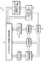
本発明の一実施形態による適応誘導安定器10の一般的な構成を示すブロック図を、図1に示す。示すように、適応誘導安定器10は、一般的には、回路の動作を制御するマイクロプロセッサ12、磁界を生成するための多タップ一次巻線14、一次巻線14に与えられる信号を生成する波形器及び駆動下位回路16、一次巻線14に与えられた信号を監視し、対応するフィードバックをマイクロプロセッサ12に提供する電流感知下位回路18、波形器及び駆動下位回路16内のキャパシタンス値を調整するためのキャパシタンススイッチ20、及び、多タップ一次巻線14のインダクタンスを調整するためのインダクタンススイッチ22を含む。マイクロプロセッサは、様々な供給業者から広く入手できる従来のマイクロプロセッサである。 A block diagram illustrating a general configuration of an
キャパシタンススイッチ20は、一般的には、コンデンサの2つのバンク、及びトランジスタのような複数のスイッチを含み、それらのスイッチは、その2つのコンデンサバンクの値を制御するようにマイクロプロセッサ12によって選択的に作動可能である。各バンクにおけるコンデンサを、可能なキャパシタンス値の所望の範囲及び分布に依って、直列又は並列に配置することができる。コンデンサの第一のバンクが、コンデンサ271と置き換わる。同様に、コンデンサの第二のバンクが、添付の特許出願に示す既存の共振探索安定器のコンデンサ272と置き換わる。実質的に、キャパシタンススイッチ20は、既存の共振探索安定器のコンデンサ271及び272を可変コンデンサにし、その値は、マイクロプロセッサ12によって制御される。そのかわりに、説明したキャパシタンススイッチ20を、可変キャパシタンスを提供することのできる他の回路で置き換えることもできる。
インダクタンススイッチ22は、一般的には、多タップ一次巻線14、及びトランジスタのような複数のスイッチを含み、それらのスイッチは、一次巻線14のインダクタンスの値を制御するように、マイクロプロセッサ12によって選択的に作動可能である。多タップ一次巻線14は、既存の共振探索安定器の一次巻線270と置き換わる。事実上、インダクタンススイッチ22は、一次巻線14の巻数を変えることにより、既存の共振探索安定器の一次巻線270を可変インダクタンスコイルにし、その値は、マイクロプロセッサ12によって制御される。そのかわりに、説明したインダクタンススイッチ22を、可変インダクタンスを提供することのできる他の回路で置き換えることもできる。 The
一般的な動作では、マイクロプロセッサ12は、電流感知下位回路18から入力を受け取るようにプログラムされ、それは、一次巻線14に与えられた電流を示している。マイクロプロセッサ12は、キャパシタンススイッチ20及びインダクタンススイッチ22を、回路に利用可能なキャパシタンス値及びインダクタンス値の範囲全体にわたって循環するように、別々に調整するようにプログラムされる。マイクロプロセッサ12は、電流感知回路18からの入力を監視し続け、さらに、キャパシタンス値及びインダクタンス値を調整して、どの値が一次巻線14に最適な電流を提供するか定める。次に、マイクロプロセッサ12は、適応安定器を最適設定にロックする。 In general operation, the
前記特許出願の共振探索誘導安定器を、適応誘導安定回路10の実施形態に適応させるのに必要な変更の幾つかを、図2の概略図に示す。 Some of the modifications necessary to adapt the patented resonant search induction ballast to the adaptive
米国特許出願第10/246,155号では、既存の共振探索安定器をずっと詳細に説明しているが、これに対して、回路の全体像は、本発明のより完全な理解に役立つであろう。安定フィードバック回路は、点Aにおいて接続され、制御回路は、点Bにおいて接続される。発振器144は、駆動146を介して、半ブリッジインバータ148に交流信号を提供する。半ブリッジインバータは、タンク回路150に電力を供給する。電流感知回路218は、発振器144にフィードバックを提供する。フィードバック回路、制御回路、発振器、半ブリッジインバータ、駆動及び電流感知回路218、加えて、他の補助回路は、上で引用された特許出願において、より完全に説明される。 US patent application Ser. No. 10 / 246,155 describes the existing resonant search ballast in greater detail, whereas the overall picture of the circuit will help a more complete understanding of the present invention. The stable feedback circuit is connected at point A and the control circuit is connected at point B. The
図2では、位相遅延を、Eにおいて挿入することができ、遅延線として制御することができるであろう。この遅延を使用して、位相を絞り、二次振幅を制御することができる。Fにおいて、スイッチキャパシタンスは、可変一次インダクタンスに基づいて、共振周波数を調整することができる。単純なトランジスタを使用して、キャパシタンスのスイッチを入れる及び切ることができる。負荷を整合させるように、一次インダクタが変化する時、キャパシタンスも変わる。Gにおいて、一次インダクタンスを切り替えて、二次回路で必要とされる電力を調整することができる。RFID又は直接通信は、必要とされる負荷を指示することができる。その負荷情報を用いて、制御プロセッサは、要求された電力を提供するために必要とされるように、インダクタンスを調整することができる。トランジスタ、及びマイクロプロセッサによって制御される一次インダクタの多タップを使って、インダクタンスを切り替えることができる。 In FIG. 2, a phase delay could be inserted at E and could be controlled as a delay line. This delay can be used to throttle the phase and control the secondary amplitude. In F, the switch capacitance can adjust the resonant frequency based on the variable primary inductance. A simple transistor can be used to switch the capacitance on and off. As the primary inductor changes, the capacitance also changes to match the load. In G, the primary inductance can be switched to adjust the power required by the secondary circuit. RFID or direct communication can indicate the required load. With that load information, the control processor can adjust the inductance as needed to provide the required power. Inductance can be switched using multiple taps of a primary inductor controlled by a transistor and a microprocessor.
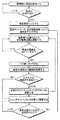
適応誘導安定回路の動作シーケンスを、図3と絡めて、より詳細に説明する。動作において、図示されたシステムは、一次巻線14に電力を与える前に、負荷が存在することを確認するまで停止する。これは電力を節約し、各誘導動力装置に、一次巻線に隣接するリードスイッチを作動させる磁気を提供することにより、行うことができる。そのかわりに、誘導動力装置が存在するときに、ユーザが電源に関与することができるように、ユーザ作動スイッチ(示されていない)を提供することもできる。更なる代替として、スイッチが、一次巻線の近くに置かれて、その存在を信号で送るとき、そのスイッチを機械的に作動させるように、誘導動力装置を構成することもできる。更なる代替として、切換機構を取り除くことができ、かつ、安定回路は、負荷の存在に関わらず、一次巻線14に電力を提供することができる。 The operation sequence of the adaptive induction stabilization circuit will be described in more detail in conjunction with FIG. In operation, the illustrated system stops until it confirms that a load is present before powering the primary winding 14. This can be done by saving power and providing each induction power unit with magnetism that activates a reed switch adjacent to the primary winding. Alternatively, a user actuated switch (not shown) can be provided so that the user can participate in the power supply when an inductive power unit is present. As a further alternative, the inductive power unit can be configured to mechanically actuate the switch when it is placed near the primary winding and signals its presence. As a further alternative, the switching mechanism can be eliminated and the ballast circuit can provide power to the primary winding 14 regardless of the presence of a load.
電源回路が作動されると、一次巻線に与えられる電流を最適化するように、回路は、その周波数を調整する。初期キャパシタンス及びインダクタンス値で、適切な動作周波数が定められた後、マイクロプロセッサは、安定回路をその動作周波数にロックし、次に、多タップ一次巻線によって利用可能なインダクタンス値の範囲全体にわたって循環し始める。インダクタンス値のどの変化の後も、マイクロプロセッサは、動作周波数をロック解除し、安定回路が共振を探索することを可能にし、一次巻線に最適な電流を提供する周波数に落ち着く。マイクロプロセッサは、どの値が一次巻線に最適な電流を提供するか定めるまで、利用可能なインダクタンス値全体にわたって循環し続ける。一実施形態では、順次走査処理を使用して、適切なインダクタンス値を定める。その走査処理を最低インダクタンス値で開始し、インダクタンス値の変化が、一次巻線に与えられる電流の減少という結果になるまで、インダクタンス値を順次上げていくことにより、これを実現する。次に、マイクロプロセッサは、最大電流が実現された一インダクタンス値まで、下げ戻るであろう。そのかわりに、走査処理を、最高インダクタンス値で始め、インダクタンス値の変化が、一次巻線に与えられた電流の減少という結果になるまで、インダクタンス値を順次下げていくこともできる。次に、マイクロプロセッサは、最大電流が実現された一インダクタンス値まで上がり戻るであろう。更なる代替として、マイクロプロセッサは、各インダクタンス値全体にわたってステップして、その対応する電流を定め、各値全体にわたってステップした後、一次巻線に最大電流を提供したインダクタンス値に戻ることもできる。 When the power circuit is activated, the circuit adjusts its frequency to optimize the current applied to the primary winding. After the appropriate operating frequency is determined with the initial capacitance and inductance values, the microprocessor locks the ballast circuit to that operating frequency and then circulates across the range of inductance values available by the multi-tap primary winding. Begin to. After any change in inductance value, the microprocessor unlocks the operating frequency, allows the ballast circuit to search for resonance, and settles to a frequency that provides the optimum current for the primary winding. The microprocessor continues to cycle through the available inductance values until it determines which value provides the optimum current for the primary winding. In one embodiment, a progressive scan process is used to determine an appropriate inductance value. This is achieved by starting the scanning process with the lowest inductance value and increasing the inductance value sequentially until the change in inductance value results in a decrease in the current applied to the primary winding. The microprocessor will then decrease back to the one inductance value where the maximum current is achieved. Alternatively, the scanning process can begin at the highest inductance value and the inductance value can be decreased sequentially until the change in inductance value results in a decrease in the current applied to the primary winding. The microprocessor will then rise back to the one inductance value where the maximum current is achieved. As a further alternative, the microprocessor can step through each inductance value to determine its corresponding current and, after stepping through each value, return to the inductance value that provided the maximum current to the primary winding.
適切なインダクタンス値が定められた後、マイクロプロセッサは、回路を所定のインダクタンス値にロックし、キャパシタンス値全体にわたって循環し始める。一実施形態では、マイクロプロセッサは、順次走査技術を使って、一次巻線に最大電流を与えるキャパシタンスを定める。インダクタンス値についての走査処理に関して上で説明したように、その走査処理は、最低キャパシタンス値から上向きに、又は、最高キャパシタンス値から下向きに進行するであろう。順次走査処理の代替として、マイクロプロセッサは、各キャパシタンス値全体にわたってステップして、その対応する電流を定め、各値全体にわたってステップした後、一次巻線に最大電流を提供したキャパシタンス値に戻ることができる。 After the appropriate inductance value is determined, the microprocessor locks the circuit to the predetermined inductance value and begins to cycle through the capacitance value. In one embodiment, the microprocessor uses a progressive scan technique to define a capacitance that provides maximum current to the primary winding. As described above with respect to the scanning process for the inductance value, the scanning process will proceed upward from the lowest capacitance value or downward from the highest capacitance value. As an alternative to the progressive scan process, the microprocessor may step through each capacitance value to determine its corresponding current and, after stepping through each value, return to the capacitance value that provided the maximum current to the primary winding. it can.
この実施形態では、適切なインダクタンス値が定められると、安定回路の周波数は、変化することが許されない。そのかわりに、キャパシタンス値のどの変化の後にも、安定回路が共振を探索することを可能にするように、マイクロプロセッサをプログラムすることもできる。 In this embodiment, once an appropriate inductance value is defined, the frequency of the ballast circuit is not allowed to change. Alternatively, the microprocessor can be programmed to allow the ballast circuit to search for resonance after any change in capacitance value.
代替の実施形態では、電源回路のキャパシタンス値のみ、又はインダクタンス値のみの調整を提供するように、マイクロプロセッサをプログラムすることもできる。前者の代替では、多タップ一次巻線を、従来の単タップ一次巻線で置き換えることができ、インダクタンススイッチを取り除くことができる。後者の代替では、コンデンサバンクを、コンデンサの単一セットで置き換えることができ、キャパシタンススイッチを取り除くことができる。更なる代替の実施形態では、インダクタンスを調整する前に、キャパシタンスを調整するように、マイクロプロセッサをプログラムすることもできる。 In alternative embodiments, the microprocessor can be programmed to provide adjustment of only the capacitance value of the power supply circuit or only the inductance value. In the former alternative, the multi-tap primary winding can be replaced with a conventional single-tap primary winding and the inductance switch can be eliminated. In the latter alternative, the capacitor bank can be replaced with a single set of capacitors and the capacitance switch can be eliminated. In a further alternative embodiment, the microprocessor can be programmed to adjust the capacitance before adjusting the inductance.
上で示すように、本発明は、共振探索安定器と絡めた使用に限定されない。他の応用例では、電流センサを安定器内に組み込んで、一次巻線に与えられている電流を示す入力を、マイクロプロセッサに提供することもできる。共振探索安定器なしでの動作では、マイクロプロセッサは、様々なキャパシタンス値、及びインダクタンス値全体にわたって、別個に循環して、一次巻線に最適な電力を提供する値を定めるであろう。 As indicated above, the present invention is not limited to use in conjunction with a resonant search ballast. In other applications, a current sensor can be incorporated into the ballast to provide an input to the microprocessor indicating the current being applied to the primary winding. In operation without a resonant search ballast, the microprocessor will circulate separately across various capacitance and inductance values to determine a value that provides optimal power to the primary winding.
更なる代替の実施形態では、適応誘導安定器10は、それ自身が位相を絞り、二次振幅を制御することを可能にする位相遅延回路(示されていない)を含むこともできる。位相遅延回路は、遅延線、又は、演算増幅器210に続く波計器及び駆動回路16に接続されたデジタル信号プロセッサ(DSP)を含むであろう。 In a further alternative embodiment, the
図4.5と絡めて、本発明の更なる代替の実施形態を説明する。この実施形態では、適応誘導安定器10'、及び誘導動力装置は、例えば従来のRF通信又は直接通信を使って、通信できる能力を持つ。 A further alternative embodiment of the present invention will be described in connection with FIG. 4.5. In this embodiment, the adaptive induction ballast 10 'and the induction power unit are capable of communicating using, for example, conventional RF communication or direct communication.
図4は、適応誘導安定器10'の一般的な構成部品を示すブロック図である。適応誘導安定器10'は、スイッチ一次インダクタンス及び一次コイル22'から分離した通信コイル(示されていない)を含む。通信コイルは、一次巻線の一部とすることができるであろう。通信コイルは、マイクロプロセッサ12'に接続され、それは、誘導動力装置から情報を受け取り、その情報に基づいて、適応誘導安定器10'の動作を生み出すように、プログラムされる。誘導動力装置はまた、一次巻線から電力を受け取る二次巻線から分離し得る、又はそれと一体化し得る通信コイルを含む。誘導動力負荷、及び適応誘導電源10'は、例えば、標準の通信回路及び標準の通信プロトコルを使った従来の通信技術及び装置を使って、通信する。 FIG. 4 is a block diagram showing general components of the
以下に示すようなことを除いて、適応安定器10'の動作は、一般的には、上で説明した安定器10の動作と同一である。安定器10'の動作の一般的なステップを示すフローチャートを、図5に示す。その通信能力の使用によって、誘導動力装置は、負荷のワット数のような負荷情報を、適応誘導安定器10'に中継することができる。適応誘導安定器10'は、適切なキャパシタンス値及びインダクタンス値を定めることにおいて、この情報を使用することができる。より具体的には、この情報を使用して、スイッチ一次インダクタンス及び一次コイル22'の一次巻線が、修正ワット数で動作していることを確実にすることができる。そうでない場合には、スイッチ一次インダクタンス及び一次コイル22'のスイッチ一次インダクタンス、及びキャパシタンススイッチ20'を使用して、一次巻線のワット数を調整することができる。この実施形態は、一次巻線を必ずしも可能最高電流値で駆動するわけではないので、幾つかの応用例では、上で説明した適応誘導安定器10よりも改善された動作を提供するであろう。むしろ、この実施形態は、一次巻線の電力出力を、誘導動力装置の電力要求と一致させ、それは、全電力が要求されない時、電力を減らし、エネルギーを節約できることを意味する。 Except as described below, the operation of the adaptive ballast 10 'is generally the same as the operation of the
図1-5の前記システムを、図6-9を参照して、さらに拡張及び説明する。 The system of FIGS. 1-5 is further expanded and described with reference to FIGS. 6-9.
図6は、本発明の一実施形態を実装する適応非接触エネルギー伝送システムを示している。非接触電源305は、遠隔装置306に誘導結合される。非接触電源305はまた、ワークステーション307にも接続される。そして次に、ネットワーク308がワークステーション307に接続される。 FIG. 6 illustrates an adaptive contactless energy transfer system that implements an embodiment of the present invention.
一実施形態では、非接触電源305が、ワークステーション307と遠隔装置306との間で通信リンクを確立し、遠隔装置306へ、及び遠隔装置306から、情報を伝達することを可能にする。遠隔装置306がPDA(携帯情報端末)である場合には、PDAからの情報を、ワークステーション307とやり取りすることができるであろう。例えば、PDAは、充電している間、カレンダー及びアドレスリストを自動的に同期させることができるであろう。更なる例として、遠隔装置306がMP3プレーヤである場合には、MP3プレーヤが充電されている間、そのMP3プレーヤへ、又はそのMP3プレーヤから、音楽をダウンロードすることができるであろう。 In one embodiment,
図7は、複数の遠隔装置と通信するための通信手段を持つ適応非接触エネルギー伝送システムの実施形態のブロック図を示している。 FIG. 7 shows a block diagram of an embodiment of an adaptive contactless energy transmission system having communication means for communicating with a plurality of remote devices.
適応非接触エネルギー伝送システムは、非接触電源305、及び遠隔装置338、340、342を持つ。 The adaptive contactless energy transmission system has a
良く知られるように、電源310は、DC(直流)電力をインバータ312に提供するDC電源である。インバータ312は、DC電力を、AC(交流)電力に変換する。インバータ312は、タンク回路314にAC電力を供給するAC電源として作動する。タンク回路314は共振回路である。タンク回路314は、遠隔装置338の二次巻線316に誘導結合される。 As is well known, the
遠隔装置338、340、342の二次巻線は、全く鉄心を持たない。破線320は、遠隔装置338、340、342と電源305との間のエアギャップを示している。 The secondary windings of the
回路センサ324は、タンク回路314の出力に結合される。回路センサ324はまた、制御装置326にも結合される。回路センサ324は、電源の動作パラメータに関する情報を提供する。例えば、回路センサが、電流センサであって、タンク回路314内の電流の位相、周波数、及び振幅に関する情報を提供することもできるであろう。
制御装置326は、インテル8051、又はモトローラ6811、又はそれらのマイクロコントローラの多数の変形のいずれかのような、以下に説明する機能を実行するようにプログラムされた多数の汎用マイクロコントローラのいずれか1つとすることができるであろう。制御装置326は、チップ上に、ROM(読み取り専用メモリ)及びRAN(ランダムアクセスメモリ)を持つことができるであろう。制御装置326は、適応誘導電源内の様々な機能を制御するための一連のアナログ及びデジタル出力を持つこともできるであろう。 The
制御装置326は、メモリ327に接続される。制御装置326はまた、駆動回路328に結合される。駆動回路328は、インバータ312の動作を管理する。駆動回路328は、インバータ312の周波数及びタイミングを管理する。制御装置326はまた、電源310にも結合される。制御装置326は、電源310のレール電圧を操作することができる。よく知られるように、電源310のレール電圧を変化させることにより、インバータ312の出力の振幅もまた変化する。 The
最後に、制御装置326は、タンク回路314の可変インダクタ330、及び可変コンデンサ332に結合される。制御装置326は、可変インダクタ330のインダクタンス、又は可変コンデンサ332のキャパシタンスを変更することができる。可変インダクタ330のインダクタンス、及び可変コンデンサ332のキャパシタンスを変更することにより、タンク回路314の共振周波数を変えることができる。 Finally, the
タンク回路314は、第一の共振周波数、及び第二の共振周波数を持つことができるであろう。タンク回路はまた、幾つかの共振周波数を持つこともできるであろう。本出願で使用される限り、「共振周波数」という語は、タンク回路314が共振する周波数帯域を参照する。よく知られるように、タンク回路は共振周波数を持つが、周波数の範囲内で共振し続けるであろう。タンク回路314は、可変インピーダンスを持つ少なくとも1つの可変インピーダンス要素を持つ。可変インピーダンスを変えることにより、タンク回路の共振周波数が変わるであろう。可変インピーダンス要素は、可変インダクタ330又は可変コンデンサ332、又はその両方とすることができるであろう。 The
可変インダクタ330は、サイリスタ制御可変インダクタ、圧縮性可変インダクタ、平行成層鉄心可変インダクタ、選択固定インダクタをタンク回路314内に置くことができる一連のインダクタ及びスイッチ、又は、任意の他の制御可能な可変インダクタとすることができるであろう。可変コンデンサは、スイッチキャパシタアレイ、選択固定コンデンサをタンク回路314内に置くことのできる一連の固定コンデンサ及びスイッチ、又は、任意の他の制御可能な可変コンデンサとすることができるであろう。 The
タンク回路314はまた、一次巻線334を含む。一次巻線334、及び可変インダクタ330は、分離して示されている。そのかわりに、一次巻線334、及び可変インダクタ330を、単一要素に結合することもできるであろう。タンク回路314は、直列共振タンク回路として示されている。並列共振タンク回路もまた、使用することができるであろう。 The
電源送受信機336もまた、制御装置に結合される。電源送受信機336は、双方向通信を可能にする装置ではなく、単純に、情報を受け取るための受信機とすることもできるであろう。電源送受信機336は、様々な遠隔装置338、340、342と通信する。明らかに、三より多い、又は少ない装置を、そのシステムで使用することができるであろう。 A power transceiver 336 is also coupled to the controller. The power transceiver 336 could simply be a receiver for receiving information rather than a device that allows two-way communication. The power transceiver 336 communicates with various
この実施形態では、非接触電源305はまた、ワークステーション307への接続のための通信インターフェース311を持つ。通信インターフェース311は、USB、ファイアワイヤ、又はRS-232のような多数の良く知られた、又は固有のインターフェースのうちのいずれかとすることができるであろう。ワークステーション307は、ネットワーク308に接続される。ネットワーク308は、LAN(ローカルエリアネットワーク)、又はインターネットとすることができるであろう。 In this embodiment, the
非接触電源305はまた、通信制御装置313も持つことができるであろう。通信制御装置313は、通信インターフェース311、及び電源送受信機336を通るデータ入力及び出力を管理する。通信制御装置313は、コード変換、プロトコル変換、バッファリング、データ圧縮、エラーチェック、同期、及び経路選択のような必須の制御機能を実行し、加えて、管理情報を収集する。通信制御装置313は、遠隔装置338、340、342とワークステーション307、又はネットワーク308内の任意の他の装置との間で、通信セッションを確立する。通信制御装置313は、フロントエンドプロセッサとすることができるであろう。制御装置326の能力によっては、通信制御装置313は、制御装置326内で実行されるソフトウェアモジュールとすることもできるであろう。 The
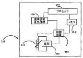
図8は、遠隔装置338のブロック図を示している。遠隔装置338は、さらに、遠隔装置340、342の代表例でもある。遠隔装置338は、負荷350を含む。負荷350は、可変二次巻線353から電力を受け取る。負荷350は、充電式バッテリ、又は任意の他の種類の負荷とすることができるであろう。 FIG. 8 shows a block diagram of the
可変二次巻線353は、鉄心なしが好ましく、それは、可変二次巻線353が、より広範囲の周波数にわたって動作することを可能にする。可変二次巻線353は、可変インダクタとして示されているが、とはいえ、その可変インダクタの代わりに、他の形式の装置も使用することができるであろう。 The variable secondary winding 353 is preferably without an iron core, which allows the variable secondary winding 353 to operate over a wider range of frequencies. The variable secondary winding 353 is shown as a variable inductor, although other types of devices could be used in place of the variable inductor.
遠隔装置制御装置352は、可変二次巻線353のインダクタンス、及び、負荷350の動作を制御する。例えば、遠隔装置制御装置352は、可変二次巻線353のインダクタンスを変更する、又は、負荷350をオン又はオフすることができる。制御装置326と同様に、遠隔装置制御装置352は、インテル8051又はモトローラ6811、或いは、それらマイクロコントローラの多くの変形のうちのいずれかのような、以下に説明する機能を実行するようにプログラムされた多数の汎用マイクロコントローラのうちのいずれか1つとすることができるであろう。制御装置352は、チップ上に、ROM(読み取り専用メモリ)、及びRAM(ランダムアクセスメモリ)を持つことができるであろう。制御装置352はまた、適応誘導電源内の様々な機能を制御するための一連のアナログ及びデジタル出力を持つこともできるであろう。 The remote
メモリ354は、とりわけ、遠隔装置338についての装置ID(識別子)番号、及び電力情報を含む。電力情報は、遠隔装置338における電圧、電流、及び消費電力の情報を示すであろう。負荷350が充電式バッテリである場合には、メモリ354は、放電率及び充電率を含むであろう。 The
遠隔装置338はまた、遠隔送受信機356を含む。遠隔送受信機356は、電源送受信機336から情報を受信、及び、電源送受信機336へ情報を送信する。WIFI、赤外線、ブルートゥース、又はセルラのような無数の様々な方法で、遠隔送受信機356、及び電源送受信機336をリンクすることができるであろう。さらに、一次巻線又は二次巻線に接続された更なるコイルを介して、送受信機は通信することができるであろう。又は、電力は、電源305によって遠隔装置338、340、342に運ばれているので、多くの様々な電力船システムのうちのいずれか1つを介して通信することもできるであろう。
そのかわりに、遠隔送受信機356は、単純に、送受信機336へ情報を送るための無線送信機とすることもできるであろう。例えば、遠隔送受信機356は、RFID(無線認証)タグとすることもできるであろう。 Instead, the
プロセッサ357は、遠隔装置338の機能構成部品を表している。例えば、遠隔装置338がデジタルカメラである場合には、プロセッサ357は、そのデジタルカメラ内のマイクロプロセッサとすることができるであろう。遠隔装置338がMP3プレーヤである場合には、プロセッサ357は、デジタル信号プロセッサ、又は、MP3ファイルを音声に変換するためのマイクロプロセッサ及びその関連回路、とすることができるであろう。遠隔装置338がPDAである場合には、プロセッサ357は、PDAの機能を提供するためのマイクロプロセッサ及びその関連回路であろう。プロセッサ357は、メモリ354にアクセスすることができるであろう。 The
プロセッサ357はまた、第二の装置送受信機356にも結合される。従って、プロセッサ357は、第二の装置送受信機356を通して、非接触電源305と通信することができ、これにより、ワークステーションのような、電源305に接続された如何なる他の装置とも通信することができるであろう。 The
通信インターフェース311の存在により、遠隔装置338は、ワークステーション307、又はネットワーク308に伝達することができるであろう。遠隔装置338とワークステーション307との間の通信をイネーブルにするために、制御装置326は、送受信機336を介して、遠隔装置338への通信リンクを確立するであろう。 Due to the presence of the
図9は、通信能力を持つ適応非接触エネルギー伝送システムの動作を示している。 FIG. 9 shows the operation of an adaptive contactless energy transmission system with communication capability.
非接触電源305は、開始した(ステップ400)後、送受信機336を介して、全ての遠隔装置をポーリングする。ステップ402。ステップ402は連続的とすることができ、そこでは、遠隔装置が存在する場合のみ、ステップ404への前進が起こるであろう。そのかわりに、ポーリングを繰り返す前に、以下のステップを実行することもできるが、その動作は、ヌルセットについて実行されるであろう。何らかの遠隔装置が存在する場合には、それは、その遠隔装置から電力使用情報を受け取る。ステップ404。 The
電力使用情報は、遠隔装置338についての電圧、電流、及び電力要求に関する実際の情報を含むことができるであろう。そのかわりに、電力使用情報を、単純に、遠隔装置338のID番号とすることもできるであろう。その場合には、制御装置326は、そのID番号を受け取り、メモリ327内に含まれる表から、遠隔装置338についての電力要求をルックアップする。 The power usage information could include actual information regarding voltage, current, and power requirements for the
全ての装置をポーリングして、各装置についての電力情報を受け取った後、次に、非接触電源305は、いずれかの装置がもはや存在しないかどうか確認する。その場合には、遠隔装置リストが更新される。ステップ408。 After polling all devices and receiving power information for each device, the
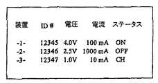
制御装置326で保持される遠隔装置リストを、図10に示す。遠隔装置リストは、各遠隔装置338、340、342についての装置ID、電圧、電流、及びステータスを含むことができるであろう。装置番号は、制御装置326によって割り当てられる。装置IDは、遠隔装置338、340、342から受け取られる。2つの遠隔装置が同じ形式である場合には、その装置IDは同じとすることができるであろう。電圧及び電流は、その装置に電力を供給するのに必要な電圧又は電流の量である。電圧及び電流は、遠隔装置338、340、342によって直接伝送されることができる、又は、メモリ327内で保持される遠隔装置のデータベースへのキーとして装置IDを使用することにより、得られることができるであろう。ステータスは、装置の現在のステータスである。例えば、装置ステータスは、「オン」、「オフ」、「充電」等とすることができるであろう。 A remote device list maintained by the
次に、非接触電源305は、いずれかの装置のステータスが変わったかどうか確認する。ステップ410。例えば、遠隔装置338は、充電式バッテリを持つことができるであろう。その充電式バッテリが完全に充電された時、遠隔装置338は、もはや電力を必要としないであろう。従って、そのステータスは、「充電」から「オフ」に変わるであろう。装置のステータスが変わる場合には、遠隔装置リストが更新される。ステップ412。 Next, the
次に、非接触電源305は、何らかの新しい装置が存在するかどうか確認する。ステップ414。その場合には、遠隔装置リストが更新される。ステップ416。次に、遠隔装置リストがチェックされる。ステップ418。リストが更新されていない場合には、システムは、再び装置をポーリングし、このプロセスが再開される。ステップ402。 The
リストが更新されている場合には、遠隔装置による電力使用が変わり、従って、非接触電源305によって供給される電力もまた変わるはずである。制御装置326は、遠隔装置リストを使って、全ての遠隔装置の電力要求を確認する。次に、全ての装置に適切に電力供給するようにシステムを再構築できるかどうか定める。ステップ420。 If the list is updated, the power usage by the remote device will change, and therefore the power supplied by the
非接触電源305が、遠隔装置の全てに電力を供給できる場合には、制御装置326が、インバータ周波数、デューティサイクル、共振周波数、及びレール電圧についての設定を算出する。さらに、制御装置は、遠隔装置338、340、342の二次巻線353の可変インピーダンスについての最良設定を定める。ステップ422。次に、そのインバータ周波数、デューティサイクル、共振周波数、及びレール電圧をセットする。ステップ424。それはまた、遠隔装置338、340、342を、二次巻線353の可変インピーダンスを所望のレベルにセットするように指示する。ステップ424。 If the
その一方で、非接触電源305が、遠隔装置の全てに電力を供給することができない場合には、制御装置326は、システム全体についての可能な最良電力設定を定める。ステップ426。次に、遠隔装置338、340、342のうちの一又はそれ以上に、オフする、又はその消費電力を変えるように指示するであろう。制御装置は、遠隔装置338、340、342の二次巻線353の可変インピーダンスについての最良設定を定める。ステップ428。次に、そのシステムについてのインバータ周波数、デューティサイクル、共振周波数、及びレール電圧をセットする。ステップ430。制御装置は、遠隔装置338、340、342に、二次巻線353の可変インピーダンスを所望のレベルにセットするように指示する。次に、システムは、装置をポーリングすることに戻り、そのプロセスを繰り返す。ステップ402。 On the other hand, if the
上記説明は、好ましい実施形態についてのものである。添付の特許請求の範囲で定められる本発明の技術的範囲から外れることなく、様々な代替及び変更が成され得り、それらは、均等論を含む特許法の主義により、解釈されるべきである。例えば、冠詞「a」、「an」、「the」又は「said」を使った単数形の請求要素への如何なる参照も、その要素を単数形に限定するものとして解釈されるべきではない。 The above description is that of the preferred embodiment. Various alternatives and modifications can be made without departing from the scope of the invention as defined in the appended claims, and they should be construed in accordance with the principles of patent law, including doctrine of equivalents. . For example, any reference to a singular claim element using the articles “a”, “an”, “the” or “said” should not be construed as limiting the element to the singular.
Claims (55)
Translated fromJapanese前記遠隔装置から情報を受け取るための受信機、及び、
前記遠隔装置から受け取られた情報に応じて、前記可変共振周波数を変えるための制御装置、
を備えることを特徴とする、前記遠隔装置へ電力を提供するための非接触電源。A resonant circuit having a primary winding to transmit variable resonant frequency and power to a remote device;
A receiver for receiving information from the remote device; and
A controller for changing the variable resonant frequency in response to information received from the remote device;
A non-contact power source for providing power to the remote device.
ことを特徴とする請求項1に記載の非接触電源。The contactless power supply according to claim 1, wherein the resonance circuit includes a variable impedance element having a variable impedance, and the control device changes the variable resonance frequency by changing the variable impedance. .
をさらに備えることを特徴とする、請求項1に記載の非接触電源。Variable capacitance,
The contactless power supply according to claim 1, further comprising:
デューティサイクル、及び動作周波数を持つインバータ、
共振周波数を持ち、前記遠隔装置へ電力を伝達するための一次巻線を持つ、前記インバータに結合される共振回路、
レール電圧を持つ、前記インバータに結合される電源、
前記レール電圧、前記共振周波数、又は前記デューティサイクルを変えるための制御装置、及び、
前記遠隔装置から電力情報を受け取るための受信機、
を備えることを特徴とする非接触電源。A contactless power supply for providing power to a remote device,
An inverter having a duty cycle and an operating frequency,
A resonant circuit coupled to the inverter having a resonant frequency and having a primary winding for transmitting power to the remote device;
A power supply coupled to the inverter having a rail voltage;
A controller for changing the rail voltage, the resonant frequency, or the duty cycle; and
A receiver for receiving power information from the remote device;
A non-contact power source comprising:
ことを特徴とする請求項5に記載の非接触電源。The contactless power supply according to claim 5, wherein the receiver is a part of a transceiver.
ことを特徴とする請求項6に記載の非接触電源。The contactless power supply according to claim 6, wherein the control device changes the rail voltage, the resonance frequency, or the duty cycle in accordance with the power information.
ことを特徴とする請求項8に記載の非接触電源。The contactless power supply according to claim 8, wherein the transceiver communicates with a plurality of remote devices.
ことを特徴とする請求項9に記載の非接触電源。The contactless power supply according to claim 9, wherein the transceiver receives power information from each of the remote devices.
ことを特徴とする請求項10に記載の非接触電源。The contactless power supply according to claim 10, wherein the transceiver creates a list in the memory for the power information.
ことを特徴とする請求項11に記載の非接触電源。The contactless power supply according to claim 11, wherein the control device determines an optimum setting for the rail voltage, the resonance frequency, or the duty cycle based on the list.
をさらに備えることを特徴とする請求項12に記載の非接触電源。A communication interface for communicating with the workstation,
The contactless power supply according to claim 12, further comprising:
ことを特徴とする請求項13に記載の非接触電源。The contactless power supply according to claim 13, wherein the control device creates a communication link between the workstation and the remote device via the transceiver.
二次巻線可変インピーダンスを持つ二次巻線、
を備えることを特徴とする、非接触電源から電力を受け取ることができる遠隔装置。Remote device controller, and
Secondary winding with secondary winding variable impedance,
A remote device capable of receiving power from a non-contact power source.
ことを特徴とする請求項15に記載の遠隔装置。16. The remote device of claim 15, wherein the remote device controller is capable of changing the secondary winding variable impedance.
をさらに備えることを特徴とする請求項16に記載の遠隔装置。A remote device transceiver for communicating with the non-contact power source;
The remote device of claim 16, further comprising:
ことを特徴とする請求項17に記載の遠隔装置。The remote device according to claim 17, wherein the control device changes the secondary winding variable impedance based on an instruction from the non-contact power source.
ことを特徴とする請求項18に記載の遠隔装置。The remote device according to claim 18, wherein the control device disables the operation of the remote device based on an instruction from the non-contact power source.
ことを特徴とする請求項19に記載の遠隔装置。The remote device according to claim 19, wherein the control device enables operation of the remote device based on an instruction from the non-contact power source.
ことを特徴とする請求項20に記載の遠隔装置。21. The remote device according to claim 20, wherein the remote device has a remote device memory containing power usage information.
ことを特徴とする請求項21に記載の遠隔装置。The remote device according to claim 21, wherein the power usage information is transmitted to the non-contact power source via the remote device transceiver.
前記遠隔装置の各々についての前記電力使用情報を受け取り、かつ、
前記電力使用情報に応じて、前記非接触電源を適応させる
ステップを含むことを特徴とする方法。A method of operating a contactless power supply that provides power to a plurality of remote devices each having power usage information,
Receiving the power usage information for each of the remote devices; and
Adapting the non-contact power source in response to the power usage information.
ことを特徴とする請求項23に記載の方法。24. The method of claim 23, wherein the contactless power source has an inverter with a duty cycle and an inverter frequency, and the step of adapting the contactless power source includes changing the duty cycle or the inverter frequency. .
ことを特徴とする請求項24に記載の方法。The non-contact power source has a resonance circuit, the resonance circuit has a resonance frequency, and the step of adapting the non-contact power source includes changing the resonance frequency of the inverter. The method described in 1.
ことを特徴とする請求項25に記載の方法。26. The method of claim 25, wherein the contactless power supply has a rail voltage and adapting the contactless power supply includes changing the rail voltage.
ステップをさらに含むことを特徴とする請求項26に記載の方法。27. The method of claim 26, further comprising determining whether the contactless power source can supply power to the plurality of remote devices.
ステップをさらに含むことを特徴とする請求項27に記載の方法。28. The method of claim 27, further comprising disabling at least one of the plurality of remote devices when the contactless power source is unable to provide power to the plurality of remote devices. the method of.
ステップをさらに含むことを特徴とする請求項28に記載の方法。29. The method of claim 28, further comprising adapting the contactless power supply when a new remote device is added to the plurality of remote devices.
ステップをさらに含むことを特徴とする請求項29に記載の方法。30. The method of claim 29, further comprising adapting the contactless power supply if one of the plurality of remote devices is removed from the plurality of remote devices.
前記二次巻線可変インピーダンスを変える
ステップをさらに含むことを特徴とする請求項30に記載の方法。At least one of the plurality of remote devices has a secondary winding, and the secondary winding has a secondary winding variable impedance;
The method of claim 30, further comprising changing the secondary winding variable impedance.
ことを特徴とする請求項31に記載の方法。The method of claim 31, wherein the step of changing the secondary winding variable impedance is performed in response to an instruction from the contactless power source.
前記遠隔装置から電力使用情報を受け取るための受信機、及び、
前記電力使用情報に応じて、前記非接触電源の可変特性を変えるための制御装置、
を備えることを特徴とする、前記遠隔装置に電力を提供するための非接触電源。A primary winding to transmit power to the remote device,
A receiver for receiving power usage information from the remote device; and
A control device for changing the variable characteristics of the non-contact power source according to the power usage information;
A non-contact power source for providing power to the remote device.
ことを特徴とする請求項34に記載の非接触電源。The contactless power supply according to claim 34, wherein the contactless power supply has a rail voltage, and the variable characteristic includes the rail voltage.
ことを特徴とする請求項35に記載の非接触電源。The contactless power supply according to claim 35, wherein the contactless power supply has a resonance circuit, the resonance circuit has a resonance frequency, and the variable characteristic includes the resonance frequency.
ことを特徴とする請求項36に記載の非接触電源。The contactless power supply according to claim 36, wherein the contactless power supply has a duty cycle, and the variable characteristic includes the resonance frequency.
ことを特徴とする請求項37に記載の非接触電源。The non-contact power source according to claim 37, wherein the non-contact power source has an inverter, the inverter has an inverter frequency, and the variable characteristic includes the inverter frequency.
を備えることを特徴とする、前記非接触電源から電力を受け取るための遠隔装置。A wireless transmitter for sending power consumption information to a non-contact power source,
A remote device for receiving power from the contactless power source.
ことを特徴とする請求項39に記載の遠隔装置。40. The remote device of claim 39, wherein the wireless transmitter comprises an RFID tag.
ことを特徴とする請求項39に記載の遠隔装置。40. The remote device of claim 39, wherein the remote device comprises a memory for storing power consumption information.
ことを特徴とする請求項41に記載の遠隔装置。42. The remote device according to claim 41, wherein the remote device comprises a control device.
前記非接触電源から電力を受け取るための可変インダクタ、及び、
前記非接触電源とのデータ通信のための送受信機、
を備えることを特徴とする遠隔装置。A remote device that can receive power from a contactless power source and can be communicatively coupled to a second device via the contactless power source,
A variable inductor for receiving power from the contactless power source; and
A transceiver for data communication with the non-contact power source,
A remote device comprising:
をさらに備えることを特徴とする請求項43に記載の遠隔装置。A control device for adjusting the variable inductor;
44. The remote device of claim 43, further comprising:
前記複数の遠隔装置とのデータ通信のための送受信機、
前記非接触電源を第二の装置と結合するための通信インターフェース、及び、
前記第二の装置と前記複数の遠隔装置との間の通信を管理するための通信制御装置、 を備えることを特徴とする非接触電源。An inductive power source for inductively applying voltage to a plurality of remote devices;
A transceiver for data communication with the plurality of remote devices;
A communication interface for coupling the contactless power supply with a second device; and
A non-contact power supply comprising: a communication control device for managing communication between the second device and the plurality of remote devices.
ことを特徴とする請求項48に記載の非接触電源。The non-contact power source according to claim 48, wherein the induction power source includes an inverter and a tank circuit.
ことを特徴とする請求項49に記載の非接触電源。The non-contact power source according to claim 49, wherein the tank circuit has a variable resonance frequency.
ことを特徴とする請求項50に記載の非接触電源。The non-contact power source according to claim 50, wherein the induction power source has an inverter, and the inverter has an inverter frequency and an inverter duty cycle.
ことを特徴とする請求項51に記載の非接触電源。52. The non-contact power source according to claim 51, wherein the induction power source has a rail voltage.
請求項52に記載の非接触電源。The non-contact power source according to claim 52, wherein the induction power source has a circuit sensor.
をさらに備えることを特徴とする請求項53に記載の非接触電源。A control device capable of changing the resonance frequency, the inverter frequency, the rail voltage, or the inverter duty cycle;
The non-contact power source according to claim 53, further comprising:
ことを特徴とする請求項53に記載の非接触電源。54. The control device according to claim 53, wherein the control device can change the resonance frequency, the inverter frequency, the rail voltage, or the inverter duty cycle in accordance with information from the plurality of remote devices. Non-contact power supply.
Applications Claiming Priority (4)
| Application Number | Priority Date | Filing Date | Title |
|---|---|---|---|
| US44479403P | 2003-02-04 | 2003-02-04 | |
| US60/444,794 | 2003-02-04 | ||
| US10/689,148US7522878B2 (en) | 1999-06-21 | 2003-10-20 | Adaptive inductive power supply with communication |
| US10/689,148 | 2003-10-20 |
Related Parent Applications (1)
| Application Number | Title | Priority Date | Filing Date |
|---|---|---|---|
| JP2009149553ADivisionJP5350909B2 (en) | 2003-02-04 | 2009-06-24 | Adaptive induction power supply with communication means |
Related Child Applications (1)
| Application Number | Title | Priority Date | Filing Date |
|---|---|---|---|
| JP2014147875ADivisionJP5986151B2 (en) | 2003-02-04 | 2014-07-18 | Adaptive induction power supply with communication means |
Publications (1)
| Publication Number | Publication Date |
|---|---|
| JP2013009590Atrue JP2013009590A (en) | 2013-01-10 |
Family
ID=32871929
Family Applications (8)
| Application Number | Title | Priority Date | Filing Date |
|---|---|---|---|
| JP2006502919APendingJP2006517778A (en) | 2003-02-04 | 2004-01-22 | Adaptive induction power supply with communication means |
| JP2009149552AExpired - LifetimeJP5511236B2 (en) | 2003-02-04 | 2009-06-24 | Adaptive induction power supply with communication means |
| JP2009149553AExpired - LifetimeJP5350909B2 (en) | 2003-02-04 | 2009-06-24 | Adaptive induction power supply with communication means |
| JP2012173603APendingJP2013009590A (en) | 2003-02-04 | 2012-08-06 | Adaptive induction power supply with communication means |
| JP2012173604APendingJP2012213324A (en) | 2003-02-04 | 2012-08-06 | Adaptive induction power supply with communication means |
| JP2014147875AExpired - LifetimeJP5986151B2 (en) | 2003-02-04 | 2014-07-18 | Adaptive induction power supply with communication means |
| JP2016228968AExpired - LifetimeJP6441883B2 (en) | 2003-02-04 | 2016-11-25 | Adaptive induction power supply with communication means |
| JP2018191583AExpired - LifetimeJP6794417B2 (en) | 2003-02-04 | 2018-10-10 | Adaptive inductive power supply with communication means |
Family Applications Before (3)
| Application Number | Title | Priority Date | Filing Date |
|---|---|---|---|
| JP2006502919APendingJP2006517778A (en) | 2003-02-04 | 2004-01-22 | Adaptive induction power supply with communication means |
| JP2009149552AExpired - LifetimeJP5511236B2 (en) | 2003-02-04 | 2009-06-24 | Adaptive induction power supply with communication means |
| JP2009149553AExpired - LifetimeJP5350909B2 (en) | 2003-02-04 | 2009-06-24 | Adaptive induction power supply with communication means |
Family Applications After (4)
| Application Number | Title | Priority Date | Filing Date |
|---|---|---|---|
| JP2012173604APendingJP2012213324A (en) | 2003-02-04 | 2012-08-06 | Adaptive induction power supply with communication means |
| JP2014147875AExpired - LifetimeJP5986151B2 (en) | 2003-02-04 | 2014-07-18 | Adaptive induction power supply with communication means |
| JP2016228968AExpired - LifetimeJP6441883B2 (en) | 2003-02-04 | 2016-11-25 | Adaptive induction power supply with communication means |
| JP2018191583AExpired - LifetimeJP6794417B2 (en) | 2003-02-04 | 2018-10-10 | Adaptive inductive power supply with communication means |
Country Status (12)
| Country | Link |
|---|---|
| US (15) | US7522878B2 (en) |
| EP (11) | EP2161807B1 (en) |
| JP (8) | JP2006517778A (en) |
| KR (3) | KR101158224B1 (en) |
| CN (4) | CN100511913C (en) |
| AT (1) | ATE476776T1 (en) |
| DE (1) | DE602004028439D1 (en) |
| ES (4) | ES2688067T3 (en) |
| MY (3) | MY144400A (en) |
| TR (2) | TR201809278T4 (en) |
| TW (1) | TW200425609A (en) |
| WO (1) | WO2004073166A2 (en) |
Families Citing this family (541)
| Publication number | Priority date | Publication date | Assignee | Title |
|---|---|---|---|---|
| US7212414B2 (en) | 1999-06-21 | 2007-05-01 | Access Business Group International, Llc | Adaptive inductive power supply |
| US7612528B2 (en)* | 1999-06-21 | 2009-11-03 | Access Business Group International Llc | Vehicle interface |
| US7522878B2 (en) | 1999-06-21 | 2009-04-21 | Access Business Group International Llc | Adaptive inductive power supply with communication |
| US7065658B1 (en) | 2001-05-18 | 2006-06-20 | Palm, Incorporated | Method and apparatus for synchronizing and recharging a connector-less portable computer system |
| US7811231B2 (en) | 2002-12-31 | 2010-10-12 | Abbott Diabetes Care Inc. | Continuous glucose monitoring system and methods of use |
| US7587287B2 (en)* | 2003-04-04 | 2009-09-08 | Abbott Diabetes Care Inc. | Method and system for transferring analyte test data |
| US7679407B2 (en)* | 2003-04-28 | 2010-03-16 | Abbott Diabetes Care Inc. | Method and apparatus for providing peak detection circuitry for data communication systems |
| US7722536B2 (en)* | 2003-07-15 | 2010-05-25 | Abbott Diabetes Care Inc. | Glucose measuring device integrated into a holster for a personal area network device |
| WO2005089103A2 (en)* | 2004-02-17 | 2005-09-29 | Therasense, Inc. | Method and system for providing data communication in continuous glucose monitoring and management system |
| US20050198245A1 (en)* | 2004-03-06 | 2005-09-08 | John Burgess | Intelligent modular remote server management system |
| EP1810185A4 (en) | 2004-06-04 | 2010-01-06 | Therasense Inc | Diabetes care host-client architecture and data management system |
| NZ535390A (en) | 2004-09-16 | 2007-10-26 | Auckland Uniservices Ltd | Inductively powered mobile sensor system |
| US9788771B2 (en) | 2006-10-23 | 2017-10-17 | Abbott Diabetes Care Inc. | Variable speed sensor insertion devices and methods of use |
| US8029441B2 (en) | 2006-02-28 | 2011-10-04 | Abbott Diabetes Care Inc. | Analyte sensor transmitter unit configuration for a data monitoring and management system |
| JP2006223008A (en)* | 2005-02-08 | 2006-08-24 | Hitachi Ltd | DC-DC converter |
| US7545272B2 (en) | 2005-02-08 | 2009-06-09 | Therasense, Inc. | RF tag on test strips, test strip vials and boxes |
| DE102005022352A1 (en)* | 2005-05-13 | 2006-11-23 | BSH Bosch und Siemens Hausgeräte GmbH | Energy transmission device |
| US7768408B2 (en) | 2005-05-17 | 2010-08-03 | Abbott Diabetes Care Inc. | Method and system for providing data management in data monitoring system |
| US7825543B2 (en)* | 2005-07-12 | 2010-11-02 | Massachusetts Institute Of Technology | Wireless energy transfer |
| CN101860089B (en) | 2005-07-12 | 2013-02-06 | 麻省理工学院 | wireless non-radiative energy transfer |
| KR100970047B1 (en)* | 2005-07-19 | 2010-07-16 | 올림푸스 메디칼 시스템즈 가부시키가이샤 | Medical instrument storage device |
| US20070042729A1 (en)* | 2005-08-16 | 2007-02-22 | Baaman David W | Inductive power supply, remote device powered by inductive power supply and method for operating same |
| US7756561B2 (en)* | 2005-09-30 | 2010-07-13 | Abbott Diabetes Care Inc. | Method and apparatus for providing rechargeable power in data monitoring and management systems |
| US7382636B2 (en)* | 2005-10-14 | 2008-06-03 | Access Business Group International Llc | System and method for powering a load |
| US7583190B2 (en)* | 2005-10-31 | 2009-09-01 | Abbott Diabetes Care Inc. | Method and apparatus for providing data communication in data monitoring and management systems |
| KR100737560B1 (en)* | 2005-11-14 | 2007-07-10 | 주식회사 팬택앤큐리텔 | Contactless battery charger |
| GB0525623D0 (en)* | 2005-12-16 | 2006-01-25 | Hill Nicholas P R | RFID reader |
| US7952322B2 (en) | 2006-01-31 | 2011-05-31 | Mojo Mobility, Inc. | Inductive power source and charging system |
| US11201500B2 (en) | 2006-01-31 | 2021-12-14 | Mojo Mobility, Inc. | Efficiencies and flexibilities in inductive (wireless) charging |
| US8169185B2 (en) | 2006-01-31 | 2012-05-01 | Mojo Mobility, Inc. | System and method for inductive charging of portable devices |
| US7989986B2 (en) | 2006-03-23 | 2011-08-02 | Access Business Group International Llc | Inductive power supply with device identification |
| US11245287B2 (en) | 2006-03-23 | 2022-02-08 | Philips Ip Ventures B.V. | Inductive power supply with device identification |
| US7355150B2 (en)* | 2006-03-23 | 2008-04-08 | Access Business Group International Llc | Food preparation system with inductive power |
| US7801582B2 (en) | 2006-03-31 | 2010-09-21 | Abbott Diabetes Care Inc. | Analyte monitoring and management system and methods therefor |
| US9675290B2 (en) | 2012-10-30 | 2017-06-13 | Abbott Diabetes Care Inc. | Sensitivity calibration of in vivo sensors used to measure analyte concentration |
| US8219173B2 (en) | 2008-09-30 | 2012-07-10 | Abbott Diabetes Care Inc. | Optimizing analyte sensor calibration |
| US7620438B2 (en) | 2006-03-31 | 2009-11-17 | Abbott Diabetes Care Inc. | Method and system for powering an electronic device |
| NZ547604A (en)* | 2006-05-30 | 2008-09-26 | John Talbot Boys | Inductive power transfer system pick-up circuit |
| US7948208B2 (en)* | 2006-06-01 | 2011-05-24 | Mojo Mobility, Inc. | Power source, charging system, and inductive receiver for mobile devices |
| US11329511B2 (en) | 2006-06-01 | 2022-05-10 | Mojo Mobility Inc. | Power source, charging system, and inductive receiver for mobile devices |
| US7826873B2 (en)* | 2006-06-08 | 2010-11-02 | Flextronics Ap, Llc | Contactless energy transmission converter |
| US9022293B2 (en) | 2006-08-31 | 2015-05-05 | Semiconductor Energy Laboratory Co., Ltd. | Semiconductor device and power receiving device |
| KR100836634B1 (en)* | 2006-10-24 | 2008-06-10 | 주식회사 한림포스텍 | Portable terminal using a contactless charger, a battery pack for charging and a contactless charger for wireless data communication and power transmission |
| US9591392B2 (en)* | 2006-11-06 | 2017-03-07 | Plantronics, Inc. | Headset-derived real-time presence and communication systems and methods |
| US8339096B2 (en)* | 2006-11-20 | 2012-12-25 | Semiconductor Energy Laboratory Co., Ltd. | Wireless power receiving device |
| TWI339471B (en)* | 2006-12-27 | 2011-03-21 | Ind Tech Res Inst | Non-contact power supply having built-in coupling detection device and coupling detection method thereof |
| CN101802942A (en) | 2007-01-29 | 2010-08-11 | 普迈公司 | Pinless power coupling |
| US20080199894A1 (en) | 2007-02-15 | 2008-08-21 | Abbott Diabetes Care, Inc. | Device and method for automatic data acquisition and/or detection |
| JP4930093B2 (en)* | 2007-02-21 | 2012-05-09 | セイコーエプソン株式会社 | Power transmission control device, power reception control device, non-contact power transmission system, power transmission device, power reception device, and electronic equipment |
| US8123686B2 (en) | 2007-03-01 | 2012-02-28 | Abbott Diabetes Care Inc. | Method and apparatus for providing rolling data in communication systems |
| EP3975372B1 (en) | 2007-03-22 | 2024-01-31 | Powermat Technologies Ltd. | Efficiency monitor for inductive power transmission |
| US20120038619A1 (en)* | 2007-03-22 | 2012-02-16 | Powermat Ltd. | System and method for controlling inductive power to multiple modules |
| US10111608B2 (en) | 2007-04-14 | 2018-10-30 | Abbott Diabetes Care Inc. | Method and apparatus for providing data processing and control in medical communication system |
| WO2008130897A2 (en) | 2007-04-14 | 2008-10-30 | Abbott Diabetes Care, Inc. | Method and apparatus for providing data processing and control in medical communication system |
| WO2008130898A1 (en) | 2007-04-14 | 2008-10-30 | Abbott Diabetes Care, Inc. | Method and apparatus for providing data processing and control in medical communication system |
| CA2683953C (en) | 2007-04-14 | 2016-08-02 | Abbott Diabetes Care Inc. | Method and apparatus for providing data processing and control in medical communication system |
| US8665091B2 (en) | 2007-05-08 | 2014-03-04 | Abbott Diabetes Care Inc. | Method and device for determining elapsed sensor life |
| US8456301B2 (en) | 2007-05-08 | 2013-06-04 | Abbott Diabetes Care Inc. | Analyte monitoring system and methods |
| US20080281179A1 (en)* | 2007-05-08 | 2008-11-13 | Abbott Diabetes Care, Inc. | Analyte monitoring system and methods |
| US7928850B2 (en) | 2007-05-08 | 2011-04-19 | Abbott Diabetes Care Inc. | Analyte monitoring system and methods |
| US8461985B2 (en) | 2007-05-08 | 2013-06-11 | Abbott Diabetes Care Inc. | Analyte monitoring system and methods |
| US20080278332A1 (en)* | 2007-05-08 | 2008-11-13 | Abbott Diabetes Care, Inc. | Analyte monitoring system and methods |
| US8260558B2 (en) | 2007-05-14 | 2012-09-04 | Abbott Diabetes Care Inc. | Method and apparatus for providing data processing and control in a medical communication system |
| US8444560B2 (en) | 2007-05-14 | 2013-05-21 | Abbott Diabetes Care Inc. | Method and apparatus for providing data processing and control in a medical communication system |
| US8239166B2 (en) | 2007-05-14 | 2012-08-07 | Abbott Diabetes Care Inc. | Method and apparatus for providing data processing and control in a medical communication system |
| US8560038B2 (en) | 2007-05-14 | 2013-10-15 | Abbott Diabetes Care Inc. | Method and apparatus for providing data processing and control in a medical communication system |
| US8600681B2 (en)* | 2007-05-14 | 2013-12-03 | Abbott Diabetes Care Inc. | Method and apparatus for providing data processing and control in a medical communication system |
| US9125548B2 (en) | 2007-05-14 | 2015-09-08 | Abbott Diabetes Care Inc. | Method and apparatus for providing data processing and control in a medical communication system |
| US10002233B2 (en) | 2007-05-14 | 2018-06-19 | Abbott Diabetes Care Inc. | Method and apparatus for providing data processing and control in a medical communication system |
| US8103471B2 (en) | 2007-05-14 | 2012-01-24 | Abbott Diabetes Care Inc. | Method and apparatus for providing data processing and control in a medical communication system |
| WO2008144616A1 (en)* | 2007-05-18 | 2008-11-27 | Heidi Kay | Lipid raft, caveolin protein, and caveolar function modulation compounds and associated synthetic and therapeutic methods |
| US8115448B2 (en) | 2007-06-01 | 2012-02-14 | Michael Sasha John | Systems and methods for wireless power |
| US9421388B2 (en) | 2007-06-01 | 2016-08-23 | Witricity Corporation | Power generation for implantable devices |
| WO2008157820A1 (en)* | 2007-06-21 | 2008-12-24 | Abbott Diabetes Care, Inc. | Health management devices and methods |
| AU2008265542B2 (en)* | 2007-06-21 | 2014-07-24 | Abbott Diabetes Care Inc. | Health monitor |
| US20090001941A1 (en)* | 2007-06-29 | 2009-01-01 | Microsoft Corporation | Inductive Powering Surface for Powering Portable Devices |
| US8160900B2 (en) | 2007-06-29 | 2012-04-17 | Abbott Diabetes Care Inc. | Analyte monitoring and management device and method to analyze the frequency of user interaction with the device |
| US8834366B2 (en) | 2007-07-31 | 2014-09-16 | Abbott Diabetes Care Inc. | Method and apparatus for providing analyte sensor calibration |
| TW200908500A (en)* | 2007-08-13 | 2009-02-16 | Amic Technology Corp | Contactless power supply system and method thereof. |
| US10069341B2 (en) | 2007-08-21 | 2018-09-04 | Auckland Uniservices Limited | Inductively powered mobile sensor system |
| GB0716679D0 (en) | 2007-08-28 | 2007-10-03 | Fells J | Inductive power supply |
| US8610312B2 (en) | 2007-09-17 | 2013-12-17 | Hideo Kikuchi | Induced power transmission circuit |
| KR20100061845A (en) | 2007-09-25 | 2010-06-09 | 파우워매트 엘티디. | Adjustable inductive power transmission platform |
| US10068701B2 (en) | 2007-09-25 | 2018-09-04 | Powermat Technologies Ltd. | Adjustable inductive power transmission platform |
| JP5346028B2 (en)* | 2007-09-28 | 2013-11-20 | アクセス ビジネス グループ インターナショナル リミテッド ライアビリティ カンパニー | Multiphase induction power supply system |
| US8656622B2 (en) | 2007-10-11 | 2014-02-25 | Ashbury International Group, Inc. | Tactical firearm systems and methods of manufacturing same |
| US8193769B2 (en) | 2007-10-18 | 2012-06-05 | Powermat Technologies, Ltd | Inductively chargeable audio devices |
| US8729734B2 (en)* | 2007-11-16 | 2014-05-20 | Qualcomm Incorporated | Wireless power bridge |
| US20100219183A1 (en) | 2007-11-19 | 2010-09-02 | Powermat Ltd. | System for inductive power provision within a bounding surface |
| US8536737B2 (en) | 2007-11-19 | 2013-09-17 | Powermat Technologies, Ltd. | System for inductive power provision in wet environments |
| US8167203B2 (en)* | 2007-12-18 | 2012-05-01 | Utc Fire & Security Americas Corporation, Inc. | Credential reader having a micro power proximity detector and method of operating the credential reader |
| US20090160261A1 (en) | 2007-12-19 | 2009-06-25 | Nokia Corporation | Wireless energy transfer |
| US8129864B2 (en)* | 2008-01-07 | 2012-03-06 | Access Business Group International Llc | Inductive power supply with duty cycle control |
| JP5556002B2 (en)* | 2008-01-09 | 2014-07-23 | セイコーエプソン株式会社 | Power transmission control device, power transmission device, non-contact power transmission system, and electronic device |
| US8188709B2 (en) | 2008-01-09 | 2012-05-29 | Seiko Epson Corporation | Power transmission control device, power transmitting device, non-contact power transmitting system, and electronic instrument |
| KR100976161B1 (en) | 2008-02-20 | 2010-08-16 | 정춘길 | Contactless charging system and its charging control method |
| KR101594286B1 (en) | 2008-02-22 | 2016-02-15 | 액세스 비지니스 그룹 인터내셔날 엘엘씨 | Magnetic positioning for inductive coupling |
| JP2011514129A (en)* | 2008-02-22 | 2011-04-28 | アクセス ビジネス グループ インターナショナル リミテッド ライアビリティ カンパニー | Induction power supply system with battery type detection function |
| US8228026B2 (en)* | 2008-02-25 | 2012-07-24 | L & P Property Management Company | Inductively coupled shelving and storage containers |
| US8421407B2 (en)* | 2008-02-25 | 2013-04-16 | L & P Property Management Company | Inductively coupled work surfaces |
| US8855554B2 (en) | 2008-03-05 | 2014-10-07 | Qualcomm Incorporated | Packaging and details of a wireless power device |
| US8338990B2 (en)* | 2008-03-13 | 2012-12-25 | Access Business Group International Llc | Inductive power supply system with multiple coil primary |
| US9960640B2 (en) | 2008-03-17 | 2018-05-01 | Powermat Technologies Ltd. | System and method for regulating inductive power transmission |
| US9960642B2 (en) | 2008-03-17 | 2018-05-01 | Powermat Technologies Ltd. | Embedded interface for wireless power transfer to electrical devices |
| CN102084442B (en) | 2008-03-17 | 2013-12-04 | 鲍尔马特技术有限公司 | Inductive transmission system |
| US9331750B2 (en) | 2008-03-17 | 2016-05-03 | Powermat Technologies Ltd. | Wireless power receiver and host control interface thereof |
| US9337902B2 (en) | 2008-03-17 | 2016-05-10 | Powermat Technologies Ltd. | System and method for providing wireless power transfer functionality to an electrical device |
| WO2009144542A1 (en)* | 2008-04-15 | 2009-12-03 | Toyota Jidosha Kabushiki Kaisha | Wireless energy transfer device |
| JP4609519B2 (en)* | 2008-04-15 | 2011-01-12 | トヨタ自動車株式会社 | Wireless energy transmission device and wireless energy transmission method |
| US8320143B2 (en) | 2008-04-15 | 2012-11-27 | Powermat Technologies, Ltd. | Bridge synchronous rectifier |
| EP2277252A4 (en) | 2008-04-21 | 2017-04-26 | Qualcomm Incorporated | Short range efficient wireless power transfer |
| JP2009268181A (en)* | 2008-04-22 | 2009-11-12 | Olympus Corp | Energy supply apparatus |
| US20110050164A1 (en) | 2008-05-07 | 2011-03-03 | Afshin Partovi | System and methods for inductive charging, and improvements and uses thereof |
| US20090284369A1 (en)* | 2008-05-13 | 2009-11-19 | Qualcomm Incorporated | Transmit power control for a wireless charging system |
| US8878393B2 (en)* | 2008-05-13 | 2014-11-04 | Qualcomm Incorporated | Wireless power transfer for vehicles |
| CN102099958B (en)* | 2008-05-14 | 2013-12-25 | 麻省理工学院 | Wireless power transfer including interference enhancement |
| US7826382B2 (en) | 2008-05-30 | 2010-11-02 | Abbott Diabetes Care Inc. | Close proximity communication device and methods |
| AU2009254785A1 (en) | 2008-06-02 | 2009-12-10 | Powermat Technologies Ltd. | Appliance mounted power outlets |
| US8253278B2 (en) | 2008-06-05 | 2012-08-28 | Qualcomm Incorporated | Ferrite antennas for wireless power transfer |
| US8981598B2 (en) | 2008-07-02 | 2015-03-17 | Powermat Technologies Ltd. | Energy efficient inductive power transmission system and method |
| US8188619B2 (en) | 2008-07-02 | 2012-05-29 | Powermat Technologies Ltd | Non resonant inductive power transmission system and method |
| US11979201B2 (en) | 2008-07-02 | 2024-05-07 | Powermat Technologies Ltd. | System and method for coded communication signals regulating inductive power transmissions |
| US8223014B2 (en) | 2008-07-02 | 2012-07-17 | Essence Security International Ltd. | Energy-conserving triggered ID system and method |
| US9124113B2 (en)* | 2008-07-07 | 2015-09-01 | Powerbyproxi Limited | Inductively coupled power receiver and method of operation |
| WO2010004560A1 (en) | 2008-07-08 | 2010-01-14 | Powermat Ltd. | Display device |
| US8111042B2 (en)* | 2008-08-05 | 2012-02-07 | Broadcom Corporation | Integrated wireless resonant power charging and communication channel |
| US8626249B2 (en)* | 2008-08-12 | 2014-01-07 | T-Mobile Usa, Inc. | Charging station that operates as an intermediary device between mobile devices and other devices |
| USD640976S1 (en) | 2008-08-28 | 2011-07-05 | Hewlett-Packard Development Company, L.P. | Support structure and/or cradle for a mobile computing device |
| JP4911148B2 (en)* | 2008-09-02 | 2012-04-04 | ソニー株式会社 | Contactless power supply |
| EP2342797A2 (en) | 2008-09-23 | 2011-07-13 | Powermat Ltd | Combined antenna and inductive power receiver |
| US8868939B2 (en) | 2008-09-26 | 2014-10-21 | Qualcomm Incorporated | Portable power supply device with outlet connector |
| US8712324B2 (en) | 2008-09-26 | 2014-04-29 | Qualcomm Incorporated | Inductive signal transfer system for computing devices |
| US8401469B2 (en)* | 2008-09-26 | 2013-03-19 | Hewlett-Packard Development Company, L.P. | Shield for use with a computing device that receives an inductive signal transmission |
| US8688037B2 (en)* | 2008-09-26 | 2014-04-01 | Hewlett-Packard Development Company, L.P. | Magnetic latching mechanism for use in mating a mobile computing device to an accessory device |
| US8527688B2 (en)* | 2008-09-26 | 2013-09-03 | Palm, Inc. | Extending device functionality amongst inductively linked devices |
| US8850045B2 (en) | 2008-09-26 | 2014-09-30 | Qualcomm Incorporated | System and method for linking and sharing resources amongst devices |
| US20110106954A1 (en)* | 2008-09-26 | 2011-05-05 | Manjirnath Chatterjee | System and method for inductively pairing devices to share data or resources |
| US8234509B2 (en)* | 2008-09-26 | 2012-07-31 | Hewlett-Packard Development Company, L.P. | Portable power supply device for mobile computing devices |
| US8385822B2 (en)* | 2008-09-26 | 2013-02-26 | Hewlett-Packard Development Company, L.P. | Orientation and presence detection for use in configuring operations of computing devices in docked environments |
| US9065423B2 (en) | 2008-09-27 | 2015-06-23 | Witricity Corporation | Wireless energy distribution system |
| US8692410B2 (en) | 2008-09-27 | 2014-04-08 | Witricity Corporation | Wireless energy transfer with frequency hopping |
| US8669676B2 (en) | 2008-09-27 | 2014-03-11 | Witricity Corporation | Wireless energy transfer across variable distances using field shaping with magnetic materials to improve the coupling factor |
| US9601266B2 (en) | 2008-09-27 | 2017-03-21 | Witricity Corporation | Multiple connected resonators with a single electronic circuit |
| US9577436B2 (en) | 2008-09-27 | 2017-02-21 | Witricity Corporation | Wireless energy transfer for implantable devices |
| US8461720B2 (en) | 2008-09-27 | 2013-06-11 | Witricity Corporation | Wireless energy transfer using conducting surfaces to shape fields and reduce loss |
| US8686598B2 (en) | 2008-09-27 | 2014-04-01 | Witricity Corporation | Wireless energy transfer for supplying power and heat to a device |
| US9601261B2 (en) | 2008-09-27 | 2017-03-21 | Witricity Corporation | Wireless energy transfer using repeater resonators |
| US9744858B2 (en) | 2008-09-27 | 2017-08-29 | Witricity Corporation | System for wireless energy distribution in a vehicle |
| US9105959B2 (en) | 2008-09-27 | 2015-08-11 | Witricity Corporation | Resonator enclosure |
| US8723366B2 (en) | 2008-09-27 | 2014-05-13 | Witricity Corporation | Wireless energy transfer resonator enclosures |
| US9035499B2 (en) | 2008-09-27 | 2015-05-19 | Witricity Corporation | Wireless energy transfer for photovoltaic panels |
| US8471410B2 (en) | 2008-09-27 | 2013-06-25 | Witricity Corporation | Wireless energy transfer over distance using field shaping to improve the coupling factor |
| US8587153B2 (en) | 2008-09-27 | 2013-11-19 | Witricity Corporation | Wireless energy transfer using high Q resonators for lighting applications |
| US8957549B2 (en) | 2008-09-27 | 2015-02-17 | Witricity Corporation | Tunable wireless energy transfer for in-vehicle applications |
| US8400017B2 (en) | 2008-09-27 | 2013-03-19 | Witricity Corporation | Wireless energy transfer for computer peripheral applications |
| US8922066B2 (en) | 2008-09-27 | 2014-12-30 | Witricity Corporation | Wireless energy transfer with multi resonator arrays for vehicle applications |
| US8901778B2 (en) | 2008-09-27 | 2014-12-02 | Witricity Corporation | Wireless energy transfer with variable size resonators for implanted medical devices |
| US8907531B2 (en) | 2008-09-27 | 2014-12-09 | Witricity Corporation | Wireless energy transfer with variable size resonators for medical applications |
| US8933594B2 (en) | 2008-09-27 | 2015-01-13 | Witricity Corporation | Wireless energy transfer for vehicles |
| US9515494B2 (en) | 2008-09-27 | 2016-12-06 | Witricity Corporation | Wireless power system including impedance matching network |
| US8552592B2 (en) | 2008-09-27 | 2013-10-08 | Witricity Corporation | Wireless energy transfer with feedback control for lighting applications |
| US8643326B2 (en) | 2008-09-27 | 2014-02-04 | Witricity Corporation | Tunable wireless energy transfer systems |
| US8461722B2 (en) | 2008-09-27 | 2013-06-11 | Witricity Corporation | Wireless energy transfer using conducting surfaces to shape field and improve K |
| US8692412B2 (en) | 2008-09-27 | 2014-04-08 | Witricity Corporation | Temperature compensation in a wireless transfer system |
| US8901779B2 (en) | 2008-09-27 | 2014-12-02 | Witricity Corporation | Wireless energy transfer with resonator arrays for medical applications |
| US8461721B2 (en) | 2008-09-27 | 2013-06-11 | Witricity Corporation | Wireless energy transfer using object positioning for low loss |
| US8946938B2 (en) | 2008-09-27 | 2015-02-03 | Witricity Corporation | Safety systems for wireless energy transfer in vehicle applications |
| EP3179640A1 (en) | 2008-09-27 | 2017-06-14 | WiTricity Corporation | Wireless energy transfer systems |
| US9246336B2 (en) | 2008-09-27 | 2016-01-26 | Witricity Corporation | Resonator optimizations for wireless energy transfer |
| US8963488B2 (en) | 2008-09-27 | 2015-02-24 | Witricity Corporation | Position insensitive wireless charging |
| US8629578B2 (en) | 2008-09-27 | 2014-01-14 | Witricity Corporation | Wireless energy transfer systems |
| US8598743B2 (en) | 2008-09-27 | 2013-12-03 | Witricity Corporation | Resonator arrays for wireless energy transfer |
| US9106203B2 (en) | 2008-09-27 | 2015-08-11 | Witricity Corporation | Secure wireless energy transfer in medical applications |
| US8410636B2 (en) | 2008-09-27 | 2013-04-02 | Witricity Corporation | Low AC resistance conductor designs |
| US8569914B2 (en) | 2008-09-27 | 2013-10-29 | Witricity Corporation | Wireless energy transfer using object positioning for improved k |
| US8928276B2 (en) | 2008-09-27 | 2015-01-06 | Witricity Corporation | Integrated repeaters for cell phone applications |
| US8772973B2 (en) | 2008-09-27 | 2014-07-08 | Witricity Corporation | Integrated resonator-shield structures |
| US8947186B2 (en) | 2008-09-27 | 2015-02-03 | Witricity Corporation | Wireless energy transfer resonator thermal management |
| US8466583B2 (en) | 2008-09-27 | 2013-06-18 | Witricity Corporation | Tunable wireless energy transfer for outdoor lighting applications |
| US8476788B2 (en) | 2008-09-27 | 2013-07-02 | Witricity Corporation | Wireless energy transfer with high-Q resonators using field shaping to improve K |
| US8482158B2 (en) | 2008-09-27 | 2013-07-09 | Witricity Corporation | Wireless energy transfer using variable size resonators and system monitoring |
| US9160203B2 (en) | 2008-09-27 | 2015-10-13 | Witricity Corporation | Wireless powered television |
| US8487480B1 (en) | 2008-09-27 | 2013-07-16 | Witricity Corporation | Wireless energy transfer resonator kit |
| US9396867B2 (en) | 2008-09-27 | 2016-07-19 | Witricity Corporation | Integrated resonator-shield structures |
| US9184595B2 (en) | 2008-09-27 | 2015-11-10 | Witricity Corporation | Wireless energy transfer in lossy environments |
| US9601270B2 (en) | 2008-09-27 | 2017-03-21 | Witricity Corporation | Low AC resistance conductor designs |
| US8304935B2 (en) | 2008-09-27 | 2012-11-06 | Witricity Corporation | Wireless energy transfer using field shaping to reduce loss |
| US8912687B2 (en) | 2008-09-27 | 2014-12-16 | Witricity Corporation | Secure wireless energy transfer for vehicle applications |
| US9318922B2 (en) | 2008-09-27 | 2016-04-19 | Witricity Corporation | Mechanically removable wireless power vehicle seat assembly |
| US9544683B2 (en) | 2008-09-27 | 2017-01-10 | Witricity Corporation | Wirelessly powered audio devices |
| US8937408B2 (en) | 2008-09-27 | 2015-01-20 | Witricity Corporation | Wireless energy transfer for medical applications |
| US8497601B2 (en) | 2008-09-27 | 2013-07-30 | Witricity Corporation | Wireless energy transfer converters |
| US9093853B2 (en) | 2008-09-27 | 2015-07-28 | Witricity Corporation | Flexible resonator attachment |
| US8587155B2 (en) | 2008-09-27 | 2013-11-19 | Witricity Corporation | Wireless energy transfer using repeater resonators |
| US8441154B2 (en) | 2008-09-27 | 2013-05-14 | Witricity Corporation | Multi-resonator wireless energy transfer for exterior lighting |
| US8324759B2 (en) | 2008-09-27 | 2012-12-04 | Witricity Corporation | Wireless energy transfer using magnetic materials to shape field and reduce loss |
| US8362651B2 (en) | 2008-10-01 | 2013-01-29 | Massachusetts Institute Of Technology | Efficient near-field wireless energy transfer using adiabatic system variations |
| JP5390827B2 (en)* | 2008-10-17 | 2014-01-15 | 旭光電機株式会社 | Power supply system |
| US9083686B2 (en)* | 2008-11-12 | 2015-07-14 | Qualcomm Incorporated | Protocol for program during startup sequence |
| JP5258521B2 (en) | 2008-11-14 | 2013-08-07 | トヨタ自動車株式会社 | Power supply system |
| CN102105186A (en)* | 2008-12-05 | 2011-06-22 | 马林克罗特公司 | Inductively coupled injector faceplate |
| US8194583B2 (en) | 2008-12-08 | 2012-06-05 | Samsung Electronics Co., Ltd. | Method and system of radio frequency (RF) power transmission in a wireless network |
| US8401595B2 (en) | 2008-12-08 | 2013-03-19 | Samsung Electronics Co., Ltd. | Method and system for integrated wireless power and data communication |
| WO2010067763A1 (en)* | 2008-12-09 | 2010-06-17 | 株式会社 豊田自動織機 | Non-contact power transmission apparatus and power transmission method using a non-contact power transmission apparatus |
| JP5114371B2 (en)* | 2008-12-09 | 2013-01-09 | 株式会社豊田自動織機 | Non-contact power transmission device |
| JP5114372B2 (en)* | 2008-12-09 | 2013-01-09 | 株式会社豊田自動織機 | Power transmission method and non-contact power transmission apparatus in non-contact power transmission apparatus |
| CN101919139B (en) | 2008-12-12 | 2014-08-20 | 翰林Postech株式会社 | Non-contact power transmission equipment |
| US9178376B2 (en) | 2008-12-12 | 2015-11-03 | Hanrim Postech Co., Ltd. | Non-contact charging station with power transmission planar spiral core, non-contact power-receiving apparatus, and method for controlling the same |
| US9219956B2 (en) | 2008-12-23 | 2015-12-22 | Keyssa, Inc. | Contactless audio adapter, and methods |
| US9191263B2 (en) | 2008-12-23 | 2015-11-17 | Keyssa, Inc. | Contactless replacement for cabled standards-based interfaces |
| JP2010158114A (en)* | 2008-12-27 | 2010-07-15 | Kyokko Denki Kk | Power supply system |
| WO2010078557A2 (en)* | 2009-01-05 | 2010-07-08 | Palm, Inc. | Interior connector scheme for accessorizing a mobile computing device with a removeable housing segment |
| AU2010203795A1 (en) | 2009-01-06 | 2011-07-14 | Access Business Group International Llc | Wireless charging system with device power compliance |
| MY166603A (en)* | 2009-01-06 | 2018-07-17 | Philips Ip Ventures B V | Comunication across an inductive link with a dynamic load |
| US20100177478A1 (en) | 2009-01-09 | 2010-07-15 | Lucius Chidi Akalanne | Cooling arrangement for an equipment assembly |
| US10215529B2 (en)* | 2009-01-16 | 2019-02-26 | Prototype Productions Incorporated Ventures Two, Llc | Accessory mount for rifle accessory rail, communication, and power transfer system—accessory attachment |
| US8497658B2 (en)* | 2009-01-22 | 2013-07-30 | Qualcomm Incorporated | Adaptive power control for wireless charging of devices |
| US9402544B2 (en) | 2009-02-03 | 2016-08-02 | Abbott Diabetes Care Inc. | Analyte sensor and apparatus for insertion of the sensor |
| US9312924B2 (en) | 2009-02-10 | 2016-04-12 | Qualcomm Incorporated | Systems and methods relating to multi-dimensional wireless charging |
| US20100201312A1 (en) | 2009-02-10 | 2010-08-12 | Qualcomm Incorporated | Wireless power transfer for portable enclosures |
| US8854224B2 (en)* | 2009-02-10 | 2014-10-07 | Qualcomm Incorporated | Conveying device information relating to wireless charging |
| WO2010097725A1 (en)* | 2009-02-27 | 2010-09-02 | Koninklijke Philips Electronics N.V. | Methods, transmission devices and transmission control system for transmitting power wirelessly |
| JP5585098B2 (en)* | 2009-03-06 | 2014-09-10 | 日産自動車株式会社 | Non-contact power supply apparatus and method |
| JP5533856B2 (en)* | 2009-03-30 | 2014-06-25 | 富士通株式会社 | Wireless power supply system, wireless power transmitting apparatus, and wireless power receiving apparatus |
| US9692485B1 (en) | 2009-03-31 | 2017-06-27 | Ronald C. Krosky | Wireless energy reception management |
| US8536736B2 (en)* | 2009-04-03 | 2013-09-17 | International Business Machines Corporation | Wireless power infrastructure |
| AU2010234396A1 (en)* | 2009-04-08 | 2011-10-27 | Access Business Group International Llc | Selectable coil array |
| JP4865001B2 (en)* | 2009-04-13 | 2012-02-01 | 株式会社日本自動車部品総合研究所 | Non-contact power supply equipment, non-contact power receiving device and non-contact power supply system |
| WO2010127050A1 (en) | 2009-04-28 | 2010-11-04 | Abbott Diabetes Care Inc. | Error detection in critical repeating data in a wireless sensor system |
| US8368556B2 (en) | 2009-04-29 | 2013-02-05 | Abbott Diabetes Care Inc. | Method and system for providing data communication in continuous glucose monitoring and management system |
| JP5510032B2 (en)* | 2009-05-14 | 2014-06-04 | 日産自動車株式会社 | Non-contact power feeding device |
| US10312750B2 (en)* | 2009-05-25 | 2019-06-04 | Koninklijke Philips N.V. | Method and device for detecting a device in a wireless power transmission system |
| WO2010138856A1 (en) | 2009-05-29 | 2010-12-02 | Abbott Diabetes Care Inc. | Medical device antenna systems having external antenna configurations |
| JP5499534B2 (en)* | 2009-07-07 | 2014-05-21 | ソニー株式会社 | Non-contact power receiving apparatus, power receiving method in non-contact power receiving apparatus, and non-contact power feeding system |
| US8954001B2 (en)* | 2009-07-21 | 2015-02-10 | Qualcomm Incorporated | Power bridge circuit for bi-directional wireless power transmission |
| US8437695B2 (en)* | 2009-07-21 | 2013-05-07 | Hewlett-Packard Development Company, L.P. | Power bridge circuit for bi-directional inductive signaling |
| US9395827B2 (en)* | 2009-07-21 | 2016-07-19 | Qualcomm Incorporated | System for detecting orientation of magnetically coupled devices |
| CA2768397A1 (en)* | 2009-07-24 | 2011-01-27 | Access Business Group International Llc | Power supply |
| US9312728B2 (en)* | 2009-08-24 | 2016-04-12 | Access Business Group International Llc | Physical and virtual identification in a wireless power network |
| JP2011050140A (en)* | 2009-08-26 | 2011-03-10 | Sony Corp | Non-contact electric power feeding apparatus, non-contact power electric receiver receiving apparatus, non-contact electric power feeding method, non-contact electric power receiving method and non-contact electric power feeding system |
| US8755815B2 (en) | 2010-08-31 | 2014-06-17 | Qualcomm Incorporated | Use of wireless access point ID for position determination |
| US8395547B2 (en) | 2009-08-27 | 2013-03-12 | Hewlett-Packard Development Company, L.P. | Location tracking for mobile computing device |
| US8993331B2 (en) | 2009-08-31 | 2015-03-31 | Abbott Diabetes Care Inc. | Analyte monitoring system and methods for managing power and noise |
| EP3001194B1 (en) | 2009-08-31 | 2019-04-17 | Abbott Diabetes Care, Inc. | Medical devices and methods |
| US8928284B2 (en) | 2009-09-10 | 2015-01-06 | Qualcomm Incorporated | Variable wireless power transmission |
| US8482160B2 (en)* | 2009-09-16 | 2013-07-09 | L & P Property Management Company | Inductively coupled power module and circuit |
| WO2011033660A1 (en)* | 2009-09-18 | 2011-03-24 | 株式会社 東芝 | Wireless power transmission device |
| WO2011036702A1 (en)* | 2009-09-24 | 2011-03-31 | 株式会社 東芝 | Wireless power transmission system |
| WO2011041531A1 (en) | 2009-09-30 | 2011-04-07 | Abbott Diabetes Care Inc. | Interconnect for on-body analyte monitoring device |
| KR101059657B1 (en)* | 2009-10-07 | 2011-08-25 | 삼성전기주식회사 | Wireless power transceiver and method |
| KR101084904B1 (en)* | 2009-10-07 | 2011-11-18 | 삼성전기주식회사 | Wireless power transceiver with communication function and wireless power transmission / reception method thereof |
| US8022775B2 (en) | 2009-10-08 | 2011-09-20 | Etymotic Research, Inc. | Systems and methods for maintaining a drive signal to a resonant circuit at a resonant frequency |
| US8237402B2 (en) | 2009-10-08 | 2012-08-07 | Etymotic Research, Inc. | Magnetically coupled battery charging system |
| US8174233B2 (en) | 2009-10-08 | 2012-05-08 | Etymotic Research, Inc. | Magnetically coupled battery charging system |
| US8174234B2 (en)* | 2009-10-08 | 2012-05-08 | Etymotic Research, Inc. | Magnetically coupled battery charging system |
| US8460816B2 (en) | 2009-10-08 | 2013-06-11 | Etymotic Research, Inc. | Rechargeable battery assemblies and methods of constructing rechargeable battery assemblies |
| KR101679580B1 (en) | 2009-10-16 | 2016-11-29 | 삼성전자주식회사 | Wireless Power Transmission Device, Wireless Power Transmission Controlling Device and Wireless Power Transmission Method |
| US8829727B2 (en)* | 2009-10-30 | 2014-09-09 | Tdk Corporation | Wireless power feeder, wireless power transmission system, and table and table lamp using the same |
| KR101197579B1 (en) | 2009-11-04 | 2012-11-06 | 한국전기연구원 | Space-adaptive Wireless Power Transmission System and Method using Resonance of Evanescent Waves |
| WO2011055905A2 (en)* | 2009-11-04 | 2011-05-12 | 한국전기연구원 | System and method for space-adaptive wireless power transmission using evanescent wave resonance |
| EP2502244A4 (en) | 2009-11-16 | 2013-07-10 | 300K Entpr Pty Ltd | Contactless coupling and method for use with an electrical appliance |
| USD674391S1 (en) | 2009-11-17 | 2013-01-15 | Hewlett-Packard Development Company, L.P. | Docking station for a computing device |
| WO2011062827A2 (en)* | 2009-11-17 | 2011-05-26 | Apple Inc. | Wireless power utilization in a local computing environment |
| EP2515414A4 (en) | 2009-11-18 | 2016-04-06 | Toshiba Kk | WIRELESS POWER TRANSMISSION DEVICE |
| CN102714430A (en) | 2009-11-19 | 2012-10-03 | 捷通国际有限公司 | Multiple use wireless power systems |
| DE102009047544A1 (en)* | 2009-12-04 | 2011-06-09 | Endress + Hauser Process Solutions Ag | Method for setting parameters of a field device power supply module |
| US20110164471A1 (en)* | 2010-01-05 | 2011-07-07 | Access Business Group International Llc | Integrated wireless power system |
| JP2011147271A (en)* | 2010-01-14 | 2011-07-28 | Sony Corp | Power supply device, power receiving device, and wireless power supply system |
| US10470010B2 (en) | 2010-01-15 | 2019-11-05 | Colt Canada Ip Holding Partnership | Networked battle system or firearm |
| KR101631499B1 (en)* | 2010-01-15 | 2016-06-24 | 삼성전자주식회사 | Wireless Power Transmission Method |
| US10337834B2 (en) | 2010-01-15 | 2019-07-02 | Colt Canada Ip Holding Partnership | Networked battle system or firearm |
| US10477618B2 (en) | 2010-01-15 | 2019-11-12 | Colt Canada Ip Holding Partnership | Networked battle system or firearm |
| US10477619B2 (en) | 2010-01-15 | 2019-11-12 | Colt Canada Ip Holding Partnership | Networked battle system or firearm |
| US9921028B2 (en)* | 2010-01-15 | 2018-03-20 | Colt Canada Ip Holding Partnership | Apparatus and method for powering and networking a rail of a firearm |
| US9823043B2 (en)* | 2010-01-15 | 2017-11-21 | Colt Canada Ip Holding Partnership | Rail for inductively powering firearm accessories |
| US20110184268A1 (en)* | 2010-01-22 | 2011-07-28 | Abbott Diabetes Care Inc. | Method, Device and System for Providing Analyte Sensor Calibration |
| JP5918146B2 (en)* | 2010-01-25 | 2016-05-18 | アクセス ビジネス グループ インターナショナル リミテッド ライアビリティ カンパニー | System and method for detecting data communication on a wireless power link |
| JP5526833B2 (en) | 2010-02-05 | 2014-06-18 | ソニー株式会社 | Wireless power transmission device |
| JP5211088B2 (en)* | 2010-02-12 | 2013-06-12 | トヨタ自動車株式会社 | Power feeding device and vehicle power feeding system |
| US8656193B2 (en)* | 2010-02-17 | 2014-02-18 | Dell Products, Lp | Power module for information handling system and methods thereof |
| US9107684B2 (en)* | 2010-03-05 | 2015-08-18 | Covidien Lp | System and method for transferring power to intrabody instruments |
| WO2011112795A1 (en)* | 2010-03-10 | 2011-09-15 | Witricity Corporation | Wireless energy transfer converters |
| EP2546956B1 (en)* | 2010-03-12 | 2021-01-20 | Samsung Electronics Co., Ltd | Method for wireless charging of a mobile terminal and mobile terminal for same |
| KR20110108596A (en)* | 2010-03-29 | 2011-10-06 | 삼성전자주식회사 | Power reciveing apparatus and wireless power transiver |
| KR101623838B1 (en)* | 2010-03-29 | 2016-06-07 | 삼성전자주식회사 | Power reciveing apparatus and wireless power transiver |
| KR101821837B1 (en) | 2010-04-08 | 2018-01-24 | 액세스 비지니스 그룹 인터내셔날 엘엘씨 | Point of sale inductive systems and methods |
| JP2011223739A (en)* | 2010-04-09 | 2011-11-04 | Sony Corp | Power supply device, power reception device, and wireless power supply system |
| US8860364B2 (en)* | 2010-04-23 | 2014-10-14 | Qualcomm Incorporated | Wireless power distribution among a plurality of receivers |
| CN102237724A (en)* | 2010-04-24 | 2011-11-09 | 祝常红 | Self-adaptive wireless charging system for electric vehicle |
| KR101744162B1 (en)* | 2010-05-03 | 2017-06-07 | 삼성전자주식회사 | Apparatus and Method of control of matching of source-target structure |
| US8427014B2 (en) | 2010-05-11 | 2013-04-23 | The Invention Science Fund I, Llc | System including wearable power receiver and wearable power-output device |
| DE102010020970A1 (en) | 2010-05-19 | 2011-11-24 | Panasonic Electronic Devices Europe Gmbh | Control device for controlling contactless electrical energy transmission between power station and receiver, has controller adjusting amplitude, frequency and phase of current, and measurement devices for measuring input and output power |
| US9413197B2 (en) | 2010-05-31 | 2016-08-09 | Fu Da Tong Technology Co., Ltd. | Inductive power supply system and intruding metal detection method thereof |
| US8772979B2 (en)* | 2011-02-01 | 2014-07-08 | Fu Da Tong Technology Co., Ltd. | Method for power self-regulation in a high-power induction type power source |
| US8841881B2 (en) | 2010-06-02 | 2014-09-23 | Bryan Marc Failing | Energy transfer with vehicles |
| KR101795827B1 (en)* | 2010-06-04 | 2017-11-08 | 액세스 비지니스 그룹 인터내셔날 엘엘씨 | Wirelessly powered dielectric barrier discharge lamp, and base station for a wirelessly powered fluid treatment system |
| EP2580837A2 (en) | 2010-06-10 | 2013-04-17 | Access Business Group International LLC | Coil configurations for inductive power transfer |
| WO2011156768A2 (en) | 2010-06-11 | 2011-12-15 | Mojo Mobility, Inc. | System for wireless power transfer that supports interoperability, and multi-pole magnets for use therewith |
| US8635046B2 (en) | 2010-06-23 | 2014-01-21 | Abbott Diabetes Care Inc. | Method and system for evaluating analyte sensor response characteristics |
| US8866495B2 (en) | 2010-06-30 | 2014-10-21 | Access Business Group International Llc | Spatial tracking system and method |
| JP5664015B2 (en)* | 2010-08-23 | 2015-02-04 | Tdk株式会社 | Coil device and non-contact power transmission device |
| KR101358280B1 (en) | 2010-08-26 | 2014-02-12 | 삼성전자주식회사 | Method and Apparatus |
| US9602168B2 (en) | 2010-08-31 | 2017-03-21 | Witricity Corporation | Communication in wireless energy transfer systems |
| US9187884B2 (en)* | 2010-09-08 | 2015-11-17 | Delta Faucet Company | Faucet including a capacitance based sensor |
| US8853889B2 (en)* | 2010-09-08 | 2014-10-07 | Sony Corporation | Communication terminal apparatus and method for supplying terminal power source |
| CN103222319B (en) | 2010-09-29 | 2016-08-10 | 高通股份有限公司 | A kind of method for mobile computing device and mobile computing device |
| US11213226B2 (en) | 2010-10-07 | 2022-01-04 | Abbott Diabetes Care Inc. | Analyte monitoring devices and methods |
| JP5674013B2 (en)* | 2010-10-08 | 2015-02-18 | ソニー株式会社 | Power supply device and power supply system |
| CN102457090A (en)* | 2010-10-14 | 2012-05-16 | 朱斯忠 | Induction charging device |
| KR101735558B1 (en)* | 2010-11-10 | 2017-05-16 | 삼성전자주식회사 | Resonance Power Transmission System and Method to Control Resonance Power Transmitting and Receiving |
| TW201236301A (en) | 2010-12-08 | 2012-09-01 | Access Business Group Int Llc | System and method for providing communications in a wireless power supply |
| NZ589865A (en)* | 2010-12-10 | 2013-06-28 | Auckland Uniservices Ltd | Inductive power transfer pick-up with separate AC and DC outputs |
| JP5656606B2 (en)* | 2010-12-16 | 2015-01-21 | 株式会社テクノバ | Power supply |
| US9231412B2 (en)* | 2010-12-29 | 2016-01-05 | National Semiconductor Corporation | Resonant system for wireless power transmission to multiple receivers |
| US10115520B2 (en) | 2011-01-18 | 2018-10-30 | Mojo Mobility, Inc. | Systems and method for wireless power transfer |
| US9178369B2 (en) | 2011-01-18 | 2015-11-03 | Mojo Mobility, Inc. | Systems and methods for providing positioning freedom, and support of different voltages, protocols, and power levels in a wireless power system |
| US9496732B2 (en) | 2011-01-18 | 2016-11-15 | Mojo Mobility, Inc. | Systems and methods for wireless power transfer |
| US11342777B2 (en) | 2011-01-18 | 2022-05-24 | Mojo Mobility, Inc. | Powering and/or charging with more than one protocol |
| CN103460615B (en) | 2011-02-07 | 2016-04-27 | 捷通国际有限公司 | Systems and methods for providing communication in a wireless power transfer system |
| DK3165868T3 (en) | 2011-02-15 | 2018-11-26 | Colt Canada Ip Holding Partnership | Apparatus and method for inductive power supply and network connection of a firearm's rail |
| JP5703823B2 (en)* | 2011-02-21 | 2015-04-22 | ソニー株式会社 | Power transmission device, power transmission method, and power transmission system |
| US8669678B2 (en)* | 2011-02-22 | 2014-03-11 | Tdk Corporation | Wireless power feeder, wireless power receiver, and wireless power transmission system |
| KR20120097239A (en)* | 2011-02-24 | 2012-09-03 | 삼성전기주식회사 | Wireless power transfer system |
| CN107019515B (en) | 2011-02-28 | 2021-02-26 | 雅培糖尿病护理公司 | Method of displaying sensor readings and analyte monitoring device and method of operating the same |
| US10136845B2 (en) | 2011-02-28 | 2018-11-27 | Abbott Diabetes Care Inc. | Devices, systems, and methods associated with analyte monitoring devices and devices incorporating the same |
| US8940085B2 (en) | 2011-03-16 | 2015-01-27 | Access Business Group International Llc | Humidifier with ultraviolet disinfection |
| WO2012129273A1 (en)* | 2011-03-22 | 2012-09-27 | Access Business Group International Llc | System and method for improved control in wireless power supply systems |
| KR101198006B1 (en) | 2011-03-23 | 2012-11-05 | 삼성전기주식회사 | Wireless power transmitter and wireless power transceiver |
| JP2015039249A (en)* | 2011-03-24 | 2015-02-26 | 田淵電機株式会社 | Wireless power transmission device |
| JP5403288B2 (en)* | 2011-03-30 | 2014-01-29 | 株式会社エクォス・リサーチ | Power transmission system |
| US9496081B2 (en) | 2011-04-08 | 2016-11-15 | Access Business Group International Llc | Counter wound inductive power supply |
| KR101813129B1 (en) | 2011-05-04 | 2017-12-28 | 삼성전자주식회사 | Wireless power transmission and reception system |
| DE102011076135A1 (en)* | 2011-05-19 | 2012-11-22 | Endress + Hauser Gmbh + Co. Kg | Method and device for communication by means of a transformer |
| WO2012165672A1 (en)* | 2011-05-31 | 2012-12-06 | 엘지전자 주식회사 | Wireless charge according to charge characteristics |
| KR101950309B1 (en)* | 2011-06-07 | 2019-02-21 | 삼성전자주식회사 | Method for controlling wireless power of receiver in wireless power transmitting/receiving system and the receiver |
| US9974472B2 (en) | 2011-06-16 | 2018-05-22 | Abbott Diabetes Care Inc. | Temperature-compensated analyte monitoring devices, systems, and methods thereof |
| KR101987283B1 (en) | 2011-06-24 | 2019-06-10 | 삼성전자주식회사 | Communication system using wireless power |
| US9270124B2 (en) | 2011-06-30 | 2016-02-23 | Semiconductor Energy Laboratory Co., Ltd. | Contactless power supply device |
| US9948145B2 (en) | 2011-07-08 | 2018-04-17 | Witricity Corporation | Wireless power transfer for a seat-vest-helmet system |
| CN108110907B (en) | 2011-08-04 | 2022-08-02 | 韦特里西提公司 | Tunable wireless power supply architecture |
| WO2013032129A1 (en) | 2011-08-26 | 2013-03-07 | Lg Innotek Co., Ltd. | Wireless power transmitter and wireless power transmission method |
| KR101286585B1 (en)* | 2011-08-30 | 2013-07-22 | 한국과학기술원 | Wireless power transmitting system using frequency splitting and method thereof |
| EP2754222B1 (en) | 2011-09-09 | 2015-11-18 | Witricity Corporation | Foreign object detection in wireless energy transfer systems |
| US20130062966A1 (en) | 2011-09-12 | 2013-03-14 | Witricity Corporation | Reconfigurable control architectures and algorithms for electric vehicle wireless energy transfer systems |
| US8742823B2 (en) | 2011-10-05 | 2014-06-03 | Texas Instruments Incorporated | Driver output pad leakage current compensation |
| US9318257B2 (en) | 2011-10-18 | 2016-04-19 | Witricity Corporation | Wireless energy transfer for packaging |
| US9069536B2 (en) | 2011-10-31 | 2015-06-30 | Abbott Diabetes Care Inc. | Electronic devices having integrated reset systems and methods thereof |
| US9622691B2 (en) | 2011-10-31 | 2017-04-18 | Abbott Diabetes Care Inc. | Model based variable risk false glucose threshold alarm prevention mechanism |
| CA2853824A1 (en) | 2011-11-04 | 2013-05-10 | Witricity Corporation | Wireless energy transfer modeling tool |
| KR101327081B1 (en)* | 2011-11-04 | 2013-11-07 | 엘지이노텍 주식회사 | Apparatus for receiving wireless power and method for controlling thereof |
| WO2013070794A2 (en) | 2011-11-07 | 2013-05-16 | Abbott Diabetes Care Inc. | Analyte monitoring device and methods |
| KR101958755B1 (en)* | 2011-11-16 | 2019-03-18 | 삼성전자주식회사 | Wireless power receiver and method for controlling thereof |
| US9317656B2 (en) | 2011-11-23 | 2016-04-19 | Abbott Diabetes Care Inc. | Compatibility mechanisms for devices in a continuous analyte monitoring system and methods thereof |
| US8710993B2 (en) | 2011-11-23 | 2014-04-29 | Abbott Diabetes Care Inc. | Mitigating single point failure of devices in an analyte monitoring system and methods thereof |
| JP6141862B2 (en)* | 2011-11-28 | 2017-06-07 | アクセス ビジネス グループ インターナショナル リミテッド ライアビリティ カンパニー | Multibridge topology |
| US9026048B2 (en) | 2011-12-05 | 2015-05-05 | Broadcom Corporation | Detecting a presence of near field communications (NFC) devices |
| JP5939780B2 (en)* | 2011-12-08 | 2016-06-22 | キヤノン株式会社 | Electronics |
| EP2797384A4 (en)* | 2011-12-20 | 2015-04-29 | Panasonic Corp | CONTACTLESS POWER APPARATUS AND CONTACTLESS POWER TRANSMISSION SYSTEM |
| CN104221251B (en)* | 2011-12-22 | 2017-12-19 | 翰林Postech株式会社 | Wireless power transmission device and its control method of wireless power signal transmission |
| US9699928B2 (en) | 2012-01-06 | 2017-07-04 | Access Business Group International Llc | Print media with inductive secondary |
| CN104025219A (en) | 2012-01-08 | 2014-09-03 | 捷通国际有限公司 | Inductive cooking system |
| TWI565248B (en) | 2012-01-08 | 2017-01-01 | 通路實業集團國際公司 | Interference mitigation for multiple inductive systems |
| JP5696058B2 (en) | 2012-01-13 | 2015-04-08 | 株式会社東芝 | Power receiving device, power transmitting device and control device |
| KR102065021B1 (en) | 2012-01-24 | 2020-01-10 | 필립스 아이피 벤쳐스 비.브이. | Wireless power control system |
| JP2015508987A (en) | 2012-01-26 | 2015-03-23 | ワイトリシティ コーポレーションWitricity Corporation | Wireless energy transmission with reduced field |
| KR20130090703A (en)* | 2012-02-06 | 2013-08-14 | 삼성전자주식회사 | Wireless power charging method and apparatus |
| US8867990B2 (en) | 2012-02-29 | 2014-10-21 | Broadcom Corporation | Detecting a presence of near field communications (NFC) devices |
| US9722447B2 (en) | 2012-03-21 | 2017-08-01 | Mojo Mobility, Inc. | System and method for charging or powering devices, such as robots, electric vehicles, or other mobile devices or equipment |
| US20130271069A1 (en) | 2012-03-21 | 2013-10-17 | Mojo Mobility, Inc. | Systems and methods for wireless power transfer |
| US9899874B2 (en)* | 2012-04-05 | 2018-02-20 | Lg Innotek Co., Ltd. | Electric power supplying device, of a wireless electric power transmission apparatus and method for supplying electric power |
| EP2856608A4 (en)* | 2012-06-04 | 2016-02-17 | Byd Co Ltd | TRANSMISSION DEVICE, WIRELESS CHARGING SYSTEM COMPRISING A TRANSMISSION DEVICE AND METHOD FOR CONTROLLING A CHARGING PROCESS THEREOF |
| US9343922B2 (en) | 2012-06-27 | 2016-05-17 | Witricity Corporation | Wireless energy transfer for rechargeable batteries |
| WO2014018969A2 (en) | 2012-07-27 | 2014-01-30 | Thoratec Corporation | Resonant power transfer system and method of estimating system state |
| WO2014018974A1 (en) | 2012-07-27 | 2014-01-30 | Thoratec Corporation | Magnetic power transmission utilizing phased transmitter coil arrays and phased receiver coil arrays |
| US10383990B2 (en) | 2012-07-27 | 2019-08-20 | Tc1 Llc | Variable capacitor for resonant power transfer systems |
| WO2014018971A1 (en) | 2012-07-27 | 2014-01-30 | Thoratec Corporation | Resonant power transfer systems with protective algorithm |
| WO2014018973A1 (en) | 2012-07-27 | 2014-01-30 | Thoratec Corporation | Resonant power transmission coils and systems |
| US10291067B2 (en) | 2012-07-27 | 2019-05-14 | Tc1 Llc | Computer modeling for resonant power transfer systems |
| US9287040B2 (en) | 2012-07-27 | 2016-03-15 | Thoratec Corporation | Self-tuning resonant power transfer systems |
| EP4257174A3 (en) | 2012-07-27 | 2023-12-27 | Tc1 Llc | Thermal management for implantable wireless power transfer systems |
| US9287607B2 (en) | 2012-07-31 | 2016-03-15 | Witricity Corporation | Resonator fine tuning |
| CA2881982C (en)* | 2012-08-16 | 2020-10-13 | Colt Canada Corporation | Apparatus and method for powering and networking a rail of a firearm |
| US9385557B2 (en) | 2012-08-23 | 2016-07-05 | At&T Mobility Ii Llc | Methods, systems, and products for charging of devices |
| US10132793B2 (en) | 2012-08-30 | 2018-11-20 | Abbott Diabetes Care Inc. | Dropout detection in continuous analyte monitoring data during data excursions |
| WO2014038265A1 (en) | 2012-09-05 | 2014-03-13 | ルネサスエレクトロニクス株式会社 | Non-contact charging device, and non-contact power supply system using same |
| US20140080409A1 (en)* | 2012-09-17 | 2014-03-20 | Qualcomm Incorporated | Static tuning of wireless transmitters |
| US9968306B2 (en) | 2012-09-17 | 2018-05-15 | Abbott Diabetes Care Inc. | Methods and apparatuses for providing adverse condition notification with enhanced wireless communication range in analyte monitoring systems |
| US9595378B2 (en) | 2012-09-19 | 2017-03-14 | Witricity Corporation | Resonator enclosure |
| WO2014052136A1 (en) | 2012-09-26 | 2014-04-03 | Abbott Diabetes Care Inc. | Method and apparatus for improving lag correction during in vivo measurement of analyte concentration with analyte concentration variability and range data |
| US9124302B2 (en) | 2012-10-11 | 2015-09-01 | Qualcomm Incorporated | Carrier frequency variation for device detection in near-field communications |
| US8977197B2 (en) | 2012-10-11 | 2015-03-10 | Qualcomm Incorporated | Circuit tuning for device detection in near-field communications |
| EP2909912B1 (en) | 2012-10-19 | 2022-08-10 | WiTricity Corporation | Foreign object detection in wireless energy transfer systems |
| US11616520B2 (en) | 2012-11-09 | 2023-03-28 | California Institute Of Technology | RF receiver |
| CN104885333B (en) | 2012-11-09 | 2018-05-15 | 加州理工学院 | Smart RF Lensing: Efficient, Dynamic, and Mobile Wireless Power Transfer |
| US11843260B2 (en) | 2012-11-09 | 2023-12-12 | California Institute Of Technology | Generator unit for wireless power transfer |
| US9842684B2 (en) | 2012-11-16 | 2017-12-12 | Witricity Corporation | Systems and methods for wireless power system with improved performance and/or ease of use |
| KR102008808B1 (en)* | 2012-12-13 | 2019-10-21 | 엘지이노텍 주식회사 | Wireless power receiver and controlling method thereof |
| US20140191709A1 (en)* | 2013-01-04 | 2014-07-10 | Roche Diagnostics Operations, Inc. | Handheld Medical Device Simultaneous Charging And In Vivo Analyte Sampling Systems And Methods |
| US9419465B2 (en)* | 2013-01-07 | 2016-08-16 | Nxp B.V. | Wireless charger |
| US9188172B2 (en) | 2013-01-10 | 2015-11-17 | Means Industries, Inc. | Compact overrunning coupling and control assembly having reduced part count and manufacturing complexity |
| RU2656613C2 (en)* | 2013-01-11 | 2018-06-06 | Конинклейке Филипс Н.В. | Wireless inductive power transfer |
| US9876535B2 (en)* | 2013-02-21 | 2018-01-23 | Qualcomm Incorporated | Modular inductive power transfer power supply and method of operation |
| WO2014130065A1 (en) | 2013-02-25 | 2014-08-28 | Access Business Group International Llc | Variable pitch spiral coil |
| US9667084B2 (en) | 2013-03-13 | 2017-05-30 | Nxp Usa, Inc. | Wireless charging systems, devices, and methods |
| US10433773B1 (en) | 2013-03-15 | 2019-10-08 | Abbott Diabetes Care Inc. | Noise rejection methods and apparatus for sparsely sampled analyte sensor data |
| EP2984731B8 (en) | 2013-03-15 | 2019-06-26 | Tc1 Llc | Malleable tets coil with improved anatomical fit |
| US9474475B1 (en) | 2013-03-15 | 2016-10-25 | Abbott Diabetes Care Inc. | Multi-rate analyte sensor data collection with sample rate configurable signal processing |
| WO2014145664A1 (en) | 2013-03-15 | 2014-09-18 | Thoratec Corporation | Integrated implantable tets housing including fins and coil loops |
| US10076285B2 (en) | 2013-03-15 | 2018-09-18 | Abbott Diabetes Care Inc. | Sensor fault detection using analyte sensor data pattern comparison |
| KR102003358B1 (en) | 2013-03-22 | 2019-07-24 | 삼성전자주식회사 | Wireless power transmitter, wireless power receiver and method for controlling each thereof |
| US9837846B2 (en) | 2013-04-12 | 2017-12-05 | Mojo Mobility, Inc. | System and method for powering or charging receivers or devices having small surface areas or volumes |
| US20150023000A1 (en) | 2013-07-17 | 2015-01-22 | Whirlpool Corporation | Lighted refrigerator shelf with overmold |
| US9857821B2 (en) | 2013-08-14 | 2018-01-02 | Witricity Corporation | Wireless power transfer frequency adjustment |
| US9847666B2 (en)* | 2013-09-03 | 2017-12-19 | Apple Inc. | Power management for inductive charging systems |
| CN108429359B (en) | 2013-09-04 | 2021-05-04 | 恩智浦美国有限公司 | Wireless power transmitter with wide input voltage range and method of operating the same |
| JP6220609B2 (en)* | 2013-09-11 | 2017-10-25 | シャープ株式会社 | Charging circuit |
| US9837866B2 (en) | 2013-10-09 | 2017-12-05 | Apple Inc. | Reducing power dissipation in inductive energy transfer systems |
| US9735584B2 (en) | 2013-10-17 | 2017-08-15 | Access Business Group International Llc | Wireless power communication |
| US20190089183A9 (en)* | 2013-10-23 | 2019-03-21 | Apple Inc. | Transmitter and receiver communication for inductive power transfer systems |
| JP6258816B2 (en) | 2013-10-29 | 2018-01-10 | パナソニック株式会社 | Wireless power transmission apparatus and wireless power transmission system |
| EP2868293B1 (en)* | 2013-10-30 | 2017-08-30 | Trisa Holding AG | Electrically Operated Toothbrush for Tooth Care |
| US10695476B2 (en) | 2013-11-11 | 2020-06-30 | Tc1 Llc | Resonant power transfer systems with communications |
| EP3072210B1 (en) | 2013-11-11 | 2023-12-20 | Tc1 Llc | Resonant power transfer systems with communications |
| EP3069358B1 (en) | 2013-11-11 | 2019-06-12 | Tc1 Llc | Hinged resonant power transfer coil |
| US9673784B2 (en) | 2013-11-21 | 2017-06-06 | Apple Inc. | Using pulsed biases to represent DC bias for charging |
| EP3072214B1 (en) | 2013-11-22 | 2018-10-10 | California Institute of Technology | Generator unit for wireless power transfer |
| US10164472B2 (en) | 2013-12-03 | 2018-12-25 | Massachusetts Institute Of Technology | Method and apparatus for wirelessly charging portable electronic devices |
| US9780573B2 (en) | 2014-02-03 | 2017-10-03 | Witricity Corporation | Wirelessly charged battery system |
| US9952266B2 (en) | 2014-02-14 | 2018-04-24 | Witricity Corporation | Object detection for wireless energy transfer systems |
| WO2015134871A1 (en) | 2014-03-06 | 2015-09-11 | Thoratec Corporation | Electrical connectors for implantable devices |
| US9716861B1 (en) | 2014-03-07 | 2017-07-25 | Steelcase Inc. | Method and system for facilitating collaboration sessions |
| US10664772B1 (en) | 2014-03-07 | 2020-05-26 | Steelcase Inc. | Method and system for facilitating collaboration sessions |
| US10027172B2 (en) | 2014-03-24 | 2018-07-17 | L&P Property Management Company | Maintaining continuous power charge in an inductive-coupling system |
| US20170185748A1 (en) | 2014-03-30 | 2017-06-29 | Abbott Diabetes Care Inc. | Method and Apparatus for Determining Meal Start and Peak Events in Analyte Monitoring Systems |
| US9966946B2 (en)* | 2014-04-02 | 2018-05-08 | Infineon Technologies Ag | System and method for a driving a radio frequency switch |
| WO2015156468A1 (en)* | 2014-04-08 | 2015-10-15 | 에스케이플래닛 주식회사 | Wireless charging apparatus and terminal, wireless charging system comprising same, method for controlling wireless charging system and recording medium having computer program recorded thereon |
| US9224433B1 (en) | 2014-04-09 | 2015-12-29 | Altera Corporation | Method and apparatus for power supply aware memory access operations in an integrated circuit |
| US9842687B2 (en) | 2014-04-17 | 2017-12-12 | Witricity Corporation | Wireless power transfer systems with shaped magnetic components |
| US9892849B2 (en) | 2014-04-17 | 2018-02-13 | Witricity Corporation | Wireless power transfer systems with shield openings |
| US9837860B2 (en) | 2014-05-05 | 2017-12-05 | Witricity Corporation | Wireless power transmission systems for elevators |
| JP2017518018A (en) | 2014-05-07 | 2017-06-29 | ワイトリシティ コーポレーションWitricity Corporation | Foreign object detection in wireless energy transmission systems |
| WO2015173847A1 (en) | 2014-05-14 | 2015-11-19 | ネオテス株式会社 | Contactless power transfer device |
| US9285283B2 (en) | 2014-05-19 | 2016-03-15 | Honeywell International Inc. | Adaptive wireless torque measurement system and method |
| US9766079B1 (en) | 2014-10-03 | 2017-09-19 | Steelcase Inc. | Method and system for locating resources and communicating within an enterprise |
| US9955318B1 (en) | 2014-06-05 | 2018-04-24 | Steelcase Inc. | Space guidance and management system and method |
| US9380682B2 (en) | 2014-06-05 | 2016-06-28 | Steelcase Inc. | Environment optimization for space based on presence and activities |
| US10433646B1 (en) | 2014-06-06 | 2019-10-08 | Steelcaase Inc. | Microclimate control systems and methods |
| US10614694B1 (en) | 2014-06-06 | 2020-04-07 | Steelcase Inc. | Powered furniture assembly |
| US11744376B2 (en) | 2014-06-06 | 2023-09-05 | Steelcase Inc. | Microclimate control systems and methods |
| US9954375B2 (en) | 2014-06-20 | 2018-04-24 | Witricity Corporation | Wireless power transfer systems for surfaces |
| US10312746B2 (en)* | 2014-06-23 | 2019-06-04 | Htc Corporation | Power providing equipment, mobile device, operating method of mobile device |
| US11103715B2 (en)* | 2014-06-27 | 2021-08-31 | Cochlear Limited | Devices and methods for charging medical devices |
| US10574091B2 (en) | 2014-07-08 | 2020-02-25 | Witricity Corporation | Enclosures for high power wireless power transfer systems |
| CN107258046B (en) | 2014-07-08 | 2020-07-17 | 无线电力公司 | Resonator equalization in wireless power transfer systems |
| US9787114B2 (en) | 2014-07-11 | 2017-10-10 | Samsung Electro-Mechanics Co., Ltd. | Wireless power transmitter and wireless power transmission system |
| DE102015112097A1 (en) | 2014-07-25 | 2016-01-28 | Minnetronix, Inc. | power scale |
| DE102015112098A1 (en) | 2014-07-25 | 2016-01-28 | Minnetronix, Inc. | Coil parameters and control |
| US9596098B1 (en) | 2014-07-31 | 2017-03-14 | iDevices, LLC | Systems and methods for communication between devices and remote systems with a power cord |
| US10454307B2 (en)* | 2014-08-04 | 2019-10-22 | Jabil Inc. | Wireless power apparatus, system and method |
| EP3183797B1 (en) | 2014-08-19 | 2020-10-07 | California Institute of Technology | Wireless power transfer |
| US9780571B2 (en)* | 2014-08-28 | 2017-10-03 | Motorola Solutions, Inc. | Methods and systems for providing a ballast load for a magnetic resonant power supply |
| WO2016034410A1 (en) | 2014-09-03 | 2016-03-10 | Koninklijke Philips N.V. | Wireless inductive power transfer |
| EP3826104B1 (en) | 2014-09-22 | 2023-05-03 | Tc1 Llc | Antenna designs for communication between a wirelessly powered implant to an external device outside the body |
| US9852388B1 (en) | 2014-10-03 | 2017-12-26 | Steelcase, Inc. | Method and system for locating resources and communicating within an enterprise |
| WO2016057525A1 (en) | 2014-10-06 | 2016-04-14 | Thoratec Corporation | Multiaxial connector for implantable devices |
| US9843217B2 (en) | 2015-01-05 | 2017-12-12 | Witricity Corporation | Wireless energy transfer for wearables |
| US10342908B2 (en) | 2015-01-14 | 2019-07-09 | Minnetronix, Inc. | Distributed transformer |
| DE102016100534A1 (en) | 2015-01-16 | 2016-07-21 | Vlad BLUVSHTEIN | Data transmission in a transcutaneous energy transmission system |
| WO2016145257A1 (en)* | 2015-03-11 | 2016-09-15 | Integrated Device Technology, Inc. | Adaptive resonant topology application in wearable devices |
| US10193395B2 (en) | 2015-04-14 | 2019-01-29 | Minnetronix, Inc. | Repeater resonator |
| US11016581B2 (en) | 2015-04-21 | 2021-05-25 | Microsoft Technology Licensing, Llc | Base station for use with digital pens |
| US9602648B2 (en) | 2015-04-30 | 2017-03-21 | Keyssa Systems, Inc. | Adapter devices for enhancing the functionality of other devices |
| US9742194B2 (en)* | 2015-05-08 | 2017-08-22 | Solantro Semiconductor Corp. | Photovoltaic power system inverter detection |
| BR112017022999A2 (en) | 2015-05-22 | 2018-07-24 | Access Business Group Int Llc | point of use water treatment system |
| EP3694081B1 (en) | 2015-05-28 | 2025-08-20 | NIKE Innovate C.V. | Transportation apparatus with nfc charger |
| US10733371B1 (en) | 2015-06-02 | 2020-08-04 | Steelcase Inc. | Template based content preparation system for use with a plurality of space types |
| JP2016225577A (en)* | 2015-06-03 | 2016-12-28 | 船井電機株式会社 | Power supply device and power reception device |
| DE202016009220U1 (en) | 2015-07-10 | 2024-07-09 | Abbott Diabetes Care, Inc. | Device and system for dynamic glucose profile response to physiological parameters |
| US10498160B2 (en) | 2015-08-03 | 2019-12-03 | Massachusetts Institute Of Technology | Efficiency maximization for device-to-device wireless charging |
| US10148126B2 (en) | 2015-08-31 | 2018-12-04 | Tc1 Llc | Wireless energy transfer system and wearables |
| US10122217B2 (en) | 2015-09-28 | 2018-11-06 | Apple Inc. | In-band signaling within wireless power transfer systems |
| US10248899B2 (en) | 2015-10-06 | 2019-04-02 | Witricity Corporation | RFID tag and transponder detection in wireless energy transfer systems |
| WO2017062552A1 (en) | 2015-10-07 | 2017-04-13 | Tc1 Llc | Resonant power transfer systems having efficiency optimization based on receiver impedance |
| US9929721B2 (en) | 2015-10-14 | 2018-03-27 | Witricity Corporation | Phase and amplitude detection in wireless energy transfer systems |
| WO2017070227A1 (en) | 2015-10-19 | 2017-04-27 | Witricity Corporation | Foreign object detection in wireless energy transfer systems |
| WO2017070009A1 (en) | 2015-10-22 | 2017-04-27 | Witricity Corporation | Dynamic tuning in wireless energy transfer systems |
| JP6487121B2 (en) | 2015-11-02 | 2019-03-20 | コーニンクレッカ フィリップス エヌ ヴェKoninklijke Philips N.V. | Wireless inductive power transmission |
| WO2017080865A1 (en) | 2015-11-09 | 2017-05-18 | Koninklijke Philips N.V. | Wireless inductive power transfer |
| US11689856B2 (en) | 2015-11-19 | 2023-06-27 | The Lovesac Company | Electronic furniture systems with integrated induction charger |
| US10075019B2 (en) | 2015-11-20 | 2018-09-11 | Witricity Corporation | Voltage source isolation in wireless power transfer systems |
| US10707698B2 (en) | 2015-11-25 | 2020-07-07 | Koninklijke Philips N.V. | Wireless inductive power transfer |
| WO2017136491A1 (en) | 2016-02-02 | 2017-08-10 | Witricity Corporation | Controlling wireless power transfer systems |
| CN114123540B (en) | 2016-02-08 | 2024-08-20 | 韦特里西提公司 | Variable capacitance device and high-power wireless energy transmission system |
| IL261831B2 (en)* | 2016-03-18 | 2024-06-01 | Global Energy Trans Co | Wireless power transmission system |
| US9921726B1 (en) | 2016-06-03 | 2018-03-20 | Steelcase Inc. | Smart workstation method and system |
| US10374661B2 (en) | 2016-06-09 | 2019-08-06 | Scott Technologies, Inc. | Resonance wireless power enabled personal protection equipment |
| US10084336B2 (en)* | 2016-07-15 | 2018-09-25 | International Business Machines Corporation | Wireless power distribution and scheduling |
| US20210307149A1 (en)* | 2016-08-22 | 2021-09-30 | Signify Holding B.V. | An interface circuit and an external circuit |
| EP4084271A1 (en) | 2016-09-21 | 2022-11-02 | Tc1 Llc | Systems and methods for locating implanted wireless power transmission devices |
| US10601250B1 (en) | 2016-09-22 | 2020-03-24 | Apple Inc. | Asymmetric duty control of a half bridge power converter |
| US10727684B2 (en) | 2016-10-10 | 2020-07-28 | Wits Co., Ltd. | Wireless power transmitter |
| CN106740152A (en)* | 2016-11-06 | 2017-05-31 | 华北电力大学 | A kind of electric automobile uses the vehicle-mounted integrated form charge-discharge circuit of shunting tap |
| US10418857B2 (en) | 2016-11-29 | 2019-09-17 | Wits Co., Ltd. | Wireless power transmitter |
| US10264213B1 (en) | 2016-12-15 | 2019-04-16 | Steelcase Inc. | Content amplification system and method |
| US10790703B2 (en)* | 2016-12-19 | 2020-09-29 | Koji Yoden | Smart wireless power transfer between devices |
| GB2597871B (en)* | 2017-01-17 | 2022-07-20 | Stannah Stairlifts Ltd | Improvements in or relating to stairlifts |
| WO2018136592A2 (en) | 2017-01-18 | 2018-07-26 | Tc1 Llc | Systems and methods for transcutaneous power transfer using microneedles |
| US11071478B2 (en) | 2017-01-23 | 2021-07-27 | Abbott Diabetes Care Inc. | Systems, devices and methods for analyte sensor insertion |
| US10978899B2 (en) | 2017-02-02 | 2021-04-13 | Apple Inc. | Wireless charging system with duty cycle control |
| US11437923B2 (en)* | 2017-02-13 | 2022-09-06 | Hamilton Sundstrand Corporation—Pcss | Variable resonant power converter with tunable inductor |
| WO2018160181A1 (en)* | 2017-03-02 | 2018-09-07 | iDevices, LLC | Systems and methods for communication between devices and remote systems with a power cord |
| WO2018175489A1 (en) | 2017-03-21 | 2018-09-27 | Abbott Diabetes Care Inc. | Methods, devices and system for providing diabetic condition diagnosis and therapy |
| JP6855878B2 (en) | 2017-03-29 | 2021-04-07 | 富士通株式会社 | Power receiver, power transmission system, and power receiver control method |
| CA3063839A1 (en)* | 2017-05-15 | 2018-11-22 | T-Worx Holdings, LLC | Power system for a firearm |
| WO2018218252A1 (en)* | 2017-05-26 | 2018-11-29 | California Institute Of Technology | Method and apparatus for dynamic rf lens focusing and tracking of wireless power recovery unit |
| WO2019006376A1 (en) | 2017-06-29 | 2019-01-03 | Witricity Corporation | Protection and control of wireless power systems |
| CN107591902A (en)* | 2017-10-27 | 2018-01-16 | 江南大学 | A kind of novel radio electric energy transmission system |
| EP4383580A3 (en)* | 2017-12-28 | 2024-08-21 | Solaredge Technologies Ltd. | Variable impedance circuit |
| WO2019135890A1 (en) | 2018-01-04 | 2019-07-11 | Tc1 Llc | Systems and methods for elastic wireless power transmission devices |
| US11018526B2 (en) | 2018-02-08 | 2021-05-25 | Massachusetts Institute Of Technology | Detuning for a resonant wireless power transfer system including cooperative power sharing |
| US10651687B2 (en) | 2018-02-08 | 2020-05-12 | Massachusetts Institute Of Technology | Detuning for a resonant wireless power transfer system including cryptography |
| US10916971B2 (en) | 2018-03-26 | 2021-02-09 | Mediatek Singapore Pte. Ltd. | Wireless power transfer ecosystem and coils operating on substantially different power levels |
| US10840707B2 (en) | 2018-08-06 | 2020-11-17 | Robert M. Lyden | Utility pole with solar modules and wireless device and method of retrofitting existing utility pole |
| US11207988B2 (en) | 2018-08-06 | 2021-12-28 | Robert M. Lyden | Electric or hybrid vehicle with wireless device and method of supplying electromagnetic energy to vehicle |
| US11444485B2 (en) | 2019-02-05 | 2022-09-13 | Mojo Mobility, Inc. | Inductive charging system with charging electronics physically separated from charging coil |
| USD881122S1 (en) | 2019-02-19 | 2020-04-14 | Kenu, Inc. | Power bank with kickstand |
| JP7105428B2 (en)* | 2019-03-28 | 2022-07-25 | 株式会社エーオーアイ・ジャパン | A wireless power supply system having a battery-equipped device fitted with a power receiving device equipped with a light unit |
| US11056930B2 (en) | 2019-05-31 | 2021-07-06 | Sigmasense, Llc. | Wireless power transfer and communications |
| TWI865577B (en)* | 2019-08-05 | 2024-12-11 | 美商立泰克實驗室公司 | Energy delivery system and method |
| US11588421B1 (en) | 2019-08-15 | 2023-02-21 | Robert M. Lyden | Receiver device of energy from the earth and its atmosphere |
| EP3835709A1 (en)* | 2019-12-11 | 2021-06-16 | FN Herstal S.A. | Mounting rail for a firearm |
| US12118178B1 (en) | 2020-04-08 | 2024-10-15 | Steelcase Inc. | Wayfinding services method and apparatus |
| US11984739B1 (en) | 2020-07-31 | 2024-05-14 | Steelcase Inc. | Remote power systems, apparatus and methods |
| CA3188510A1 (en) | 2020-08-31 | 2022-03-03 | Vivek S. RAO | Systems, devices, and methods for analyte sensor insertion |
| EP4313668A1 (en)* | 2021-04-01 | 2024-02-07 | Veturex Inc. | A plug-in module for wireless charging |
| US20220341697A1 (en)* | 2021-04-21 | 2022-10-27 | T-Worx Holdings, LLC | Electrical power source for a firearm |
| CN214755753U (en)* | 2021-05-13 | 2021-11-16 | 宁波微鹅电子科技有限公司 | A wireless charging device |
| JP7731222B2 (en)* | 2021-05-26 | 2025-08-29 | オムロン株式会社 | Resonant power conversion circuit and contactless power supply system |
| CN113439725B (en)* | 2021-06-25 | 2022-04-29 | 正能环境科技发展有限公司 | Water body ovum killing system and method |
| US12074533B2 (en) | 2022-07-29 | 2024-08-27 | Avago Technologies International Sales Pte. Limited | Rectifier fast load ballast |
| CN115648959B (en)* | 2022-10-26 | 2024-06-18 | 西南交通大学 | Rail transit contactless power supply system |
Citations (3)
| Publication number | Priority date | Publication date | Assignee | Title |
|---|---|---|---|---|
| JPH01258191A (en)* | 1988-04-08 | 1989-10-16 | Toppan Printing Co Ltd | information card device |
| JPH0696300A (en)* | 1992-09-14 | 1994-04-08 | Masuo Ikeuchi | Non-contact type ic card by electromagnetic induction coupling and reader/writer |
| JPH10322247A (en)* | 1997-05-21 | 1998-12-04 | Mitsubishi Electric Corp | Wireless transmission equipment |
Family Cites Families (264)
| Publication number | Priority date | Publication date | Assignee | Title |
|---|---|---|---|---|
| US549328A (en)* | 1895-11-05 | Fare-register | ||
| US6880A (en)* | 1849-11-20 | Auger | ||
| US455573A (en)* | 1891-07-07 | Marshall mcdonald | ||
| WO1993011509A1 (en) | 1991-12-04 | 1993-06-10 | Citizen Watch Co., Ltd. | Data carrier |
| NL6403530A (en) | 1963-04-06 | 1964-10-07 | ||
| US3455466A (en) | 1967-04-17 | 1969-07-15 | Int Harvester Co | Gravity drop accumulator for automatic bale wagon |
| US3590382A (en)* | 1967-12-20 | 1971-06-29 | Frank M Kenney | Wireless stereo sound speaker system and modulator-oscillator circuit |
| US6452482B1 (en) | 1999-12-30 | 2002-09-17 | Ambient Corporation | Inductive coupling of a data signal to a power transmission cable |
| US3949268A (en)* | 1971-02-11 | 1976-04-06 | Burkhard Von Mangoldt | Ballast unit for gas discharge lamps such as fluorescent tubes or the like |
| FR2314778A1 (en)* | 1975-06-18 | 1977-01-14 | Rech Geolog Miniere | VIBRATING TABLE FOR GRAVIMETRIC SEPARATION OF FINE PARTICLES |
| GB1542662A (en) | 1975-09-12 | 1979-03-21 | Matsushita Electric Industrial Co Ltd | Power supply |
| US4181950A (en)* | 1977-09-30 | 1980-01-01 | Westinghouse Electric Corp. | Adaptive priority determination power demand control method |
| EP0003010A1 (en)* | 1977-12-27 | 1979-07-11 | United Technologies Corporation | Method and apparatus for limiting the power demand in heating-ventilation-air conditioning |
| US5446346A (en) | 1978-03-20 | 1995-08-29 | Nilssen; Ole K. | Electronic ballast with controlled DC supply voltage |
| US5757144A (en)* | 1980-08-14 | 1998-05-26 | Nilssen; Ole K. | Gas discharge lamp ballasting means |
| US4388524A (en)* | 1981-09-16 | 1983-06-14 | Walton Charles A | Electronic identification and recognition system with code changeable reactance |
| GB2124042B (en) | 1982-06-01 | 1986-10-01 | Control Logic | Reduction of harmonics in gas discharge lamp ballasts |
| JPS5978496A (en) | 1982-06-01 | 1984-05-07 | コントロ−ル・ロジツク(プロプライエトリ−)リミテイド | Method of reducing harmonic wave components of gas discharge ballast lamp and gas discharge ballast lamp |
| JPS5978496U (en) | 1982-11-19 | 1984-05-28 | 不二サッシ株式会社 | roll screen door |
| GB8324568D0 (en)* | 1983-09-14 | 1983-10-19 | Moore Business Forms Inc | Business forms assemblies |
| US4675648A (en) | 1984-04-17 | 1987-06-23 | Honeywell Inc. | Passive signal coupler between power distribution systems for the transmission of data signals over the power lines |
| US6075340A (en)* | 1985-11-12 | 2000-06-13 | Intermec Ip Corp. | Battery pack having memory |
| US6472827B1 (en) | 1984-10-05 | 2002-10-29 | Ole K. Nilssen | Parallel-resonant inverter-type fluorescent lamp ballast |
| CA1333408C (en) | 1984-10-16 | 1994-12-06 | Calvin E. Grubbs | Electronic ballast circuit for fluorescent lamps |
| US4644321A (en)* | 1984-10-22 | 1987-02-17 | Westinghouse Electric Corp. | Wireless power line communication apparatus |
| JPS6196699U (en) | 1984-11-29 | 1986-06-21 | ||
| US4641126A (en) | 1984-12-07 | 1987-02-03 | Ferranti-Subsea Systems, Ltd. | Multiple-mode electrical power and communications interface |
| US4639714A (en)* | 1984-12-21 | 1987-01-27 | Ferranti Subsea Systems, Ltd. | Combined power and control signal transmission system |
| US4818855A (en)* | 1985-01-11 | 1989-04-04 | Indala Corporation | Identification system |
| JPH0696300B2 (en) | 1986-05-08 | 1994-11-30 | 日本電気株式会社 | Color recording device |
| US4800328A (en)* | 1986-07-18 | 1989-01-24 | Inductran Inc. | Inductive power coupling with constant voltage output |
| GB2197107B (en) | 1986-11-03 | 1990-12-12 | Mars Inc | Data-storing devices |
| ZA892468B (en)* | 1988-04-11 | 1989-12-27 | Uniscan Ltd | Improvements in or relating to cutting elements foactuator and communication system r rotary drill bits |
| US5187414A (en)* | 1988-07-15 | 1993-02-16 | North American Philips Corporation | Fluorescent lamp controllers |
| JP2820706B2 (en)* | 1989-03-02 | 1998-11-05 | 株式会社日本自動車部品総合研究所 | Power supply device having coil for electromagnetic coupling |
| US4914539A (en)* | 1989-03-15 | 1990-04-03 | The Boeing Company | Regulator for inductively coupled power distribution system |
| US5818127A (en) | 1989-04-28 | 1998-10-06 | Videocom, Inc. | Transmission of FM video signals over various lines |
| JP2548415B2 (en) | 1990-01-08 | 1996-10-30 | シャープ株式会社 | Power supply |
| JP2934689B2 (en) | 1990-11-16 | 1999-08-16 | 本田技研工業株式会社 | Inverter device |
| US5241160A (en)* | 1990-12-28 | 1993-08-31 | On Track Innovations Ltd. | System and method for the non-contact transmission of data |
| US5450076A (en)* | 1991-01-25 | 1995-09-12 | Siemens Aktiengesellschaft | Method for reducing power loss in devices for contactless data and energy transmission, and apparatus for performing the method |
| US5266926A (en)* | 1991-05-31 | 1993-11-30 | Avid Marketing, Inc. | Signal transmission and tag power consumption measurement circuit for an inductive reader |
| US5814900A (en)* | 1991-07-30 | 1998-09-29 | Ulrich Schwan | Device for combined transmission of energy and electric signals |
| US5450305A (en)* | 1991-08-12 | 1995-09-12 | Auckland Uniservices Limited | Resonant power supplies |
| DE4128314A1 (en) | 1991-08-27 | 1993-03-04 | Diehl Gmbh & Co | POWER SUPPLY CIRCUIT |
| NL9101590A (en) | 1991-09-20 | 1993-04-16 | Ericsson Radio Systems Bv | SYSTEM FOR CHARGING A RECHARGEABLE BATTERY FROM A PORTABLE UNIT IN A RACK. |
| US5341280A (en)* | 1991-09-27 | 1994-08-23 | Electric Power Research Institute | Contactless coaxial winding transformer power transfer system |
| US5325046A (en) | 1991-12-18 | 1994-06-28 | Apple Computer, Inc. | Inductive wireless data connection |
| GB2262634B (en)* | 1991-12-18 | 1995-07-12 | Apple Computer | Power connection scheme |
| GB9204200D0 (en) | 1992-02-27 | 1992-04-08 | Goble Nigel M | An inductive loop power transmission system |
| EP0561309B1 (en)* | 1992-03-16 | 1997-05-28 | Eastman Kodak Company | Device for transferring electrical signals and electric energy to the memory device of a cassette |
| US5229652A (en)* | 1992-04-20 | 1993-07-20 | Hough Wayne E | Non-contact data and power connector for computer based modules |
| US5272615A (en)* | 1992-05-01 | 1993-12-21 | Wert Harry E | Digital controlled inverter and method |
| AU4093493A (en)* | 1992-05-10 | 1993-12-13 | Auckland Uniservices Limited | A non-contact power distribution system |
| US5637973A (en)* | 1992-06-18 | 1997-06-10 | Kabushiki Kaisha Yaskawa Denki | Noncontacting electric power transfer apparatus, noncontacting signal transfer apparatus, split-type mechanical apparatus employing these transfer apparatus and a control method for controlling same |
| AU4626893A (en) | 1992-09-14 | 1994-03-24 | Aprex Corporation | Contactless communication system |
| JP3197625B2 (en)* | 1992-09-29 | 2001-08-13 | 三洋電機株式会社 | Charger having inductive inverter circuit |
| DE4233861A1 (en) | 1992-10-08 | 1994-04-14 | Aqua Signal Ag | Control appts. for high voltage gas discharge lamps - has high frequency circuit with transformer secondary having resonance circuit allowing variable frequency |
| JP3344593B2 (en)* | 1992-10-13 | 2002-11-11 | 株式会社ソニー木原研究所 | Wireless power supply |
| US5434396A (en)* | 1992-11-10 | 1995-07-18 | Xicor Inc. | Wireless powering and communication system for communicating data between a host system and a stand-alone device |
| ATE201787T1 (en)* | 1992-11-25 | 2001-06-15 | Simmonds Precision Products | DATA PROCESSING STRUCTURES AND METHODS |
| US5406174A (en)* | 1992-12-16 | 1995-04-11 | U. S. Philips Corporation | Discharge lamp operating circuit with frequency control of dimming and lamp electrode heating |
| US5374875A (en) | 1993-02-16 | 1994-12-20 | Motorola Lighting, Inc. | High-power factor circuit for energizing gas discharge lamps |
| US5434477A (en) | 1993-03-22 | 1995-07-18 | Motorola Lighting, Inc. | Circuit for powering a fluorescent lamp having a transistor common to both inverter and the boost converter and method for operating such a circuit |
| GB9310545D0 (en) | 1993-05-21 | 1993-07-07 | Era Patents Ltd | Power coupling |
| JP3207294B2 (en)* | 1993-06-02 | 2001-09-10 | 株式会社安川電機 | Free hydraulic system |
| TW302591B (en) | 1993-06-24 | 1997-04-11 | Samsung Electronics Co Ltd | |
| US5796216A (en)* | 1993-07-16 | 1998-08-18 | Delta Power Supply, Inc. | Electronic ignition enhancing circuit having both fundamental and harmonic resonant circuits as well as a DC offset |
| JP3409145B2 (en)* | 1993-07-26 | 2003-05-26 | 任天堂株式会社 | Small electrical equipment |
| US5455466A (en)* | 1993-07-29 | 1995-10-03 | Dell Usa, L.P. | Inductive coupling system for power and data transfer |
| JP2733817B2 (en) | 1993-08-30 | 1998-03-30 | 昌和 牛嶋 | Inverter circuit for discharge tube |
| JP3399630B2 (en)* | 1993-09-27 | 2003-04-21 | 株式会社日立製作所 | Bus system |
| US5644286A (en)* | 1993-10-04 | 1997-07-01 | Lockheed Martin Corporation | Power bus digital communication system |
| WO1995011544A1 (en)* | 1993-10-21 | 1995-04-27 | Auckland Uniservices Limited | A flux concentrator for an inductive power transfer system |
| JPH07153577A (en) | 1993-11-26 | 1995-06-16 | Tokin Corp | Lighting system |
| US5476488A (en) | 1993-12-15 | 1995-12-19 | Pacesetter, Inc. | Telemetry system power control for implantable medical devices |
| DE69512217T2 (en)* | 1994-02-21 | 1999-12-30 | Kabushiki Kaisha Yaskawa Denki, Kitakyushu | DIRECTLY ACTING CONTACTLESS ELECTRICAL POWER CABLE |
| US5493287A (en) | 1994-03-07 | 1996-02-20 | Motorola, Inc. | Method of remotely reading a group of meters |
| TW307980B (en) | 1994-04-28 | 1997-06-11 | Toshiba Light Technic Kk | |
| DE4418518A1 (en) | 1994-05-27 | 1995-11-30 | Philips Patentverwaltung | Power generator with a transformer |
| JP2671809B2 (en)* | 1994-06-30 | 1997-11-05 | 日本電気株式会社 | Non-contact charging device |
| GB9416411D0 (en) | 1994-08-13 | 1994-10-05 | Cheltenham Induction Heating L | Driving apparatus |
| DE4434185A1 (en)* | 1994-09-24 | 1996-03-28 | Philips Patentverwaltung | Circuit arrangement for feeding at least one load |
| JP3588148B2 (en)* | 1994-09-29 | 2004-11-10 | 三洋電機株式会社 | Charging stand for electric toothbrush |
| JP2950739B2 (en)* | 1994-11-11 | 1999-09-20 | 沖電気工業株式会社 | Dual mode transmitter |
| US5670833A (en)* | 1994-11-23 | 1997-09-23 | General Signal Power Systems, Inc. | Power transfer method and apparatus for uninterruptible power systems |
| GB9424051D0 (en) | 1994-11-29 | 1995-01-18 | Cheltenham Induction Heating L | Induction heating coil |
| US5686887A (en) | 1994-12-07 | 1997-11-11 | Schoeferisch Aeusserung Anstalt | Electronic locating device |
| JPH08214473A (en) | 1995-02-02 | 1996-08-20 | Technova:Kk | Non-contact power transmitting device |
| JP3487387B2 (en) | 1995-02-28 | 2004-01-19 | 東芝ライテック株式会社 | Power supply device, discharge lamp lighting device and lighting device |
| US5596567A (en) | 1995-03-31 | 1997-01-21 | Motorola, Inc. | Wireless battery charging system |
| US5982764A (en)* | 1995-05-18 | 1999-11-09 | Aura Communications, Inc. | Time-multiplexed short-range magnetic communications |
| JP3391149B2 (en)* | 1995-06-09 | 2003-03-31 | 株式会社ダイフク | Contactless power supply equipment for mobile objects |
| US5862461A (en)* | 1995-08-31 | 1999-01-19 | Sony Corporation | Transmitting apparatus and method of adjusting gain of signal to be transmitted, and receiving apparatus and method of adjusting gain of received signal |
| JPH09103037A (en) | 1995-10-05 | 1997-04-15 | Nippon Ido Tsushin Kk | Power supply device, power supply device and power supply system |
| US5646835A (en)* | 1995-11-20 | 1997-07-08 | General Electric Company | Series resonant converter |
| JP2723100B2 (en)* | 1995-12-15 | 1998-03-09 | 日本電気株式会社 | Portable information terminal device and its communication system |
| JP3687177B2 (en) | 1996-03-29 | 2005-08-24 | 東芝ライテック株式会社 | Discharge lamp lighting device and lighting device |
| EP0890214B1 (en) | 1996-03-29 | 2001-08-01 | Newage International Limited | Alternating current machines |
| US5808422A (en)* | 1996-05-10 | 1998-09-15 | Philips Electronics North America | Lamp ballast with lamp rectification detection circuitry |
| DE19621076C2 (en) | 1996-05-24 | 2001-06-28 | Siemens Ag | Device and method for the contactless transmission of energy or data |
| JPH09326736A (en)* | 1996-06-03 | 1997-12-16 | Mitsubishi Electric Corp | Secondary side circuit device for wireless transmission / reception system and induction coil for wireless transmission / reception system |
| JPH1014139A (en) | 1996-06-17 | 1998-01-16 | Nec Corp | Power transmission device |
| JPH1012197A (en) | 1996-06-17 | 1998-01-16 | Toshiba Lighting & Technol Corp | Electrodeless discharge lamp, electrodeless discharge lamp device, electrodeless discharge lamp lighting device, ultraviolet irradiation device and fluid treatment device |
| JPH1041089A (en) | 1996-07-18 | 1998-02-13 | Tec Corp | Discharge lamp lighting device |
| US5781399A (en)* | 1996-08-05 | 1998-07-14 | Lanigan; William P. | Energy efficient control circuit for solenoid actuated locking device |
| US5864580A (en)* | 1996-08-26 | 1999-01-26 | Hid Corporation | Miniature wireless modem |
| JP3351255B2 (en)* | 1996-08-29 | 2002-11-25 | 株式会社豊田自動織機 | Communication antenna unit and mobile communication system |
| US5940447A (en)* | 1996-08-30 | 1999-08-17 | Motorola, Inc. | Wireless powered communication device using power signal sampling and method |
| JP3402953B2 (en)* | 1996-09-13 | 2003-05-06 | 株式会社東芝 | Communication method, communication system and communication device |
| SG54559A1 (en) | 1996-09-13 | 1998-11-16 | Hitachi Ltd | Power transmission system ic card and information communication system using ic card |
| US5920155A (en)* | 1996-10-28 | 1999-07-06 | Matsushita Electric Works, Ltd. | Electronic ballast for discharge lamps |
| US7158012B2 (en) | 1996-11-01 | 2007-01-02 | Foster-Miller, Inc. | Non-invasive powerline communications system |
| EP0886906A1 (en)* | 1996-11-20 | 1998-12-30 | Koninklijke Philips Electronics N.V. | An induction charging apparatus and an electronic device |
| DE19649682C2 (en)* | 1996-11-29 | 2003-03-13 | Schleifring Und Appbau Gmbh | Device for broadband signal or energy transmission between mutually movable units |
| US5734254A (en)* | 1996-12-06 | 1998-03-31 | Hewlett-Packard Company | Battery pack and charging system for a portable electronic device |
| FR2756953B1 (en)* | 1996-12-10 | 1999-12-24 | Innovatron Ind Sa | PORTABLE TELEALIMENTAL OBJECT FOR CONTACTLESS COMMUNICATION WITH A TERMINAL |
| JPH10215530A (en) | 1997-01-28 | 1998-08-11 | Matsushita Electric Works Ltd | Non-contact power transmission device |
| US6006274A (en)* | 1997-01-30 | 1999-12-21 | 3Com Corporation | Method and apparatus using a pass through personal computer connected to both a local communication link and a computer network for indentifying and synchronizing a preferred computer with a portable computer |
| JPH10225020A (en)* | 1997-02-03 | 1998-08-21 | Sony Corp | Non-contact electric power supply device |
| JPH10225129A (en) | 1997-02-13 | 1998-08-21 | Ishikawajima Harima Heavy Ind Co Ltd | Non-contact power supply equipment |
| JP4067595B2 (en)* | 1997-02-20 | 2008-03-26 | 富士通株式会社 | Non-contact charging device compatible with multiple devices |
| US5889384A (en)* | 1997-02-20 | 1999-03-30 | Ericsson Inc. | Power transfer and voltage level conversion for a battery-powered electronic device |
| JP3595646B2 (en)* | 1997-03-19 | 2004-12-02 | 株式会社カージオペーシングリサーチ・ラボラトリー | Biological implantation device |
| US5903764A (en)* | 1997-05-02 | 1999-05-11 | Micro International, Ltd. | Smart battery selector offering power conversion internally within a portable device |
| US5929604A (en)* | 1997-06-18 | 1999-07-27 | Ericsson, Inc. | Battery-discharge-protection system for electronic accessories used in vehicles containing a battery |
| JP2934758B2 (en) | 1997-07-03 | 1999-08-16 | 株式会社セイバン | Shoulder strap upper end attachment for carrying bag |
| DE19735624C1 (en)* | 1997-08-18 | 1998-12-10 | Daimler Benz Ag | Method of inductive transfer of electrical power to several moving loads |
| DE19735685A1 (en)* | 1997-08-19 | 1999-02-25 | Wampfler Ag | Non contact electrical energy transmission device for personal vehicle |
| US5872703A (en)* | 1997-08-25 | 1999-02-16 | The Charles Machine Works, Inc. | System and method for regulating power in tank circuits having a bridge configuration |
| US6233343B1 (en)* | 1997-09-26 | 2001-05-15 | Hewlett-Packard Company | Power adapter having a speaker for an electronic device |
| US6272545B1 (en)* | 1997-10-24 | 2001-08-07 | Microsoft Corporation | System and method for interaction between one or more desktop computers and one or more mobile devices |
| US6211799B1 (en)* | 1997-11-06 | 2001-04-03 | Massachusetts Institute Of Technology | Method and apparatus for transbody transmission of power and information |
| JP3840765B2 (en) | 1997-11-21 | 2006-11-01 | 神鋼電機株式会社 | Primary power supply side power supply device for contactless power transfer system |
| JP3247328B2 (en)* | 1997-12-09 | 2002-01-15 | 浩 坂本 | Non-contact power transmission device |
| US5905372A (en) | 1997-12-17 | 1999-05-18 | Motorola, Inc. | Apparatus and method for delivering power to a contactless portable data device |
| JPH11188113A (en) | 1997-12-26 | 1999-07-13 | Nec Corp | POWER TRANSMISSION SYSTEM, POWER TRANSMISSION METHOD, AND ELECTRIC STIMULATION DEVICE HAVING THE POWER TRANSMISSION SYSTEM |
| US6205448B1 (en)* | 1998-01-30 | 2001-03-20 | 3Com Corporation | Method and apparatus of synchronizing two computer systems supporting multiple synchronization techniques |
| US6331744B1 (en)* | 1998-02-10 | 2001-12-18 | Light Sciences Corporation | Contactless energy transfer apparatus |
| US20030030342A1 (en)* | 1998-02-10 | 2003-02-13 | Chen James C. | Contactless energy transfer apparatus |
| JP3747677B2 (en)* | 1998-03-03 | 2006-02-22 | セイコーエプソン株式会社 | Electronics |
| US6348679B1 (en)* | 1998-03-17 | 2002-02-19 | Ameritherm, Inc. | RF active compositions for use in adhesion, bonding and coating |
| JP3744680B2 (en)* | 1998-03-31 | 2006-02-15 | 富士通株式会社 | Power supply device and method for controlling power supply circuit |
| JP3702091B2 (en)* | 1998-03-31 | 2005-10-05 | 富士通株式会社 | Power supply device and method for controlling power supply circuit |
| US6173899B1 (en)* | 1998-04-03 | 2001-01-16 | Alexander Rozin | Method and system for contactless energy transmission and data exchange between a terminal and IC card |
| FR2778196B1 (en)* | 1998-04-30 | 2000-06-23 | Valeo Securite Habitacle | MOTOR VEHICLE DOOR LOCK |
| US5982276A (en) | 1998-05-07 | 1999-11-09 | Media Fusion Corp. | Magnetic field based power transmission line communication method and system |
| US6188211B1 (en)* | 1998-05-13 | 2001-02-13 | Texas Instruments Incorporated | Current-efficient low-drop-out voltage regulator with improved load regulation and frequency response |
| JPH11341711A (en) | 1998-05-21 | 1999-12-10 | Sony Corp | Noncontact power supply circuit |
| JP3531477B2 (en)* | 1998-06-05 | 2004-05-31 | 株式会社日立製作所 | Contactless card communication method and integrated circuit used for the communication |
| US6047214A (en)* | 1998-06-09 | 2000-04-04 | North Carolina State University | System and method for powering, controlling, and communicating with multiple inductively-powered devices |
| FI107655B (en) | 1998-06-11 | 2001-09-14 | Innoware Oy | Electronic control circuit |
| US6005368A (en)* | 1998-06-30 | 1999-12-21 | Digital Equipment Corporation | Charging system for computer with docking station |
| US6255635B1 (en)* | 1998-07-10 | 2001-07-03 | Ameritherm, Inc. | System and method for providing RF power to a load |
| US6072362A (en)* | 1998-07-10 | 2000-06-06 | Ameritherm, Inc. | System for enabling a full-bridge switch-mode amplifier to recover all reactive energy |
| US5963012A (en) | 1998-07-13 | 1999-10-05 | Motorola, Inc. | Wireless battery charging system having adaptive parameter sensing |
| JP3535746B2 (en) | 1998-08-20 | 2004-06-07 | ソニーケミカル株式会社 | Flexible substrate manufacturing method |
| CN1326085C (en)* | 1998-07-31 | 2007-07-11 | 松下电器产业株式会社 | IC card, terminal device and communication system |
| DE19837675A1 (en) | 1998-08-19 | 2000-02-24 | Nokia Technology Gmbh | Charging device for accumulators in a mobile electrical device with inductive energy transfer |
| ATE256963T1 (en)* | 1998-09-15 | 2004-01-15 | Quality Light Electronics S A | RESONANCE IGNITION DEVICE FOR DISCHARGE LAMPS |
| DE29816725U1 (en)* | 1998-09-17 | 1999-01-14 | Chao, Wen-Chung, Yungho, Taipeh | Charging device for mobile phones |
| US6181082B1 (en)* | 1998-10-15 | 2001-01-30 | Electro-Mag International, Inc. | Ballast power control circuit |
| GB9823356D0 (en)* | 1998-10-27 | 1998-12-23 | Philips Electronics Nv | Data transfer |
| US6415388B1 (en)* | 1998-10-30 | 2002-07-02 | Intel Corporation | Method and apparatus for power throttling in a microprocessor using a closed loop feedback system |
| JP2000166129A (en)* | 1998-11-26 | 2000-06-16 | Sanyo Electric Co Ltd | Method and apparatus for reducing stand-by power of noncontact charger |
| US6289237B1 (en)* | 1998-12-22 | 2001-09-11 | University Of Pittsburgh Of The Commonwealth System Of Higher Education | Apparatus for energizing a remote station and related method |
| US6191552B1 (en)* | 1999-01-25 | 2001-02-20 | Dell Usa, L.P. | External universal battery charging apparatus and method |
| AU3221600A (en)* | 1999-02-04 | 2000-08-25 | Electric Power Research Institute, Inc. | Apparatus and method for implementing digital communications on a power line |
| JP2000243356A (en)* | 1999-02-23 | 2000-09-08 | Hamamatsu Photonics Kk | Hollow cathode lamp |
| US6151222A (en) | 1999-03-02 | 2000-11-21 | Delco Electronics Corp. | Dual voltage automotive electrical system with sub-resonant DC-DC converter |
| WO2000054387A1 (en) | 1999-03-10 | 2000-09-14 | Ea Technology Limited | Battery chargers |
| GB9905539D0 (en)* | 1999-03-10 | 1999-05-05 | Ea Tech Ltd | Battery chargers |
| US6157258A (en)* | 1999-03-17 | 2000-12-05 | Ameritherm, Inc. | High frequency power amplifier |
| JP3494067B2 (en)* | 1999-03-19 | 2004-02-03 | 日本電信電話株式会社 | Base station communication device and power supply method for portable wireless communication device |
| TW463399B (en) | 1999-03-19 | 2001-11-11 | Seiko Epson Corp | Electronic device |
| FI107580B (en) | 1999-03-30 | 2001-08-31 | Innoware Oy | Power supply for a fluorescent lamp |
| JP2000295796A (en) | 1999-04-02 | 2000-10-20 | Tokin Corp | Contactless power supply |
| US6212430B1 (en)* | 1999-05-03 | 2001-04-03 | Abiomed, Inc. | Electromagnetic field source with detection of position of secondary coil in relation to multiple primary coils |
| US6127799A (en)* | 1999-05-14 | 2000-10-03 | Gte Internetworking Incorporated | Method and apparatus for wireless powering and recharging |
| US6430069B1 (en)* | 1999-05-14 | 2002-08-06 | Intel Corporation | Contactless connectors for use in a high frequency alternating current power distribution system |
| ATE333432T1 (en)* | 1999-05-25 | 2006-08-15 | Inventio Ag | DEVICE FOR TRANSFERRING ENERGY TO A VEHICLE OF A TRANSPORT SYSTEM |
| GB2350733B (en)* | 1999-06-03 | 2003-02-12 | Cheltenham Induction Heating L | Power supply |
| AU4926700A (en)* | 1999-06-11 | 2001-01-02 | Abb Research Ltd | Method and assembly for the wireless supply of electric energy to a number of actuators, actuator and primary winding therefor and system for a machine with a number of actuators |
| US6825620B2 (en) | 1999-06-21 | 2004-11-30 | Access Business Group International Llc | Inductively coupled ballast circuit |
| US6436299B1 (en)* | 1999-06-21 | 2002-08-20 | Amway Corporation | Water treatment system with an inductively coupled ballast |
| US7612528B2 (en) | 1999-06-21 | 2009-11-03 | Access Business Group International Llc | Vehicle interface |
| US7212414B2 (en)* | 1999-06-21 | 2007-05-01 | Access Business Group International, Llc | Adaptive inductive power supply |
| AU5487800A (en) | 1999-06-21 | 2001-01-09 | Amway Corporation | Fluid treatment system |
| US7522878B2 (en)* | 1999-06-21 | 2009-04-21 | Access Business Group International Llc | Adaptive inductive power supply with communication |
| US7518267B2 (en)* | 2003-02-04 | 2009-04-14 | Access Business Group International Llc | Power adapter for a remote device |
| US7385357B2 (en)* | 1999-06-21 | 2008-06-10 | Access Business Group International Llc | Inductively coupled ballast circuit |
| US7126450B2 (en)* | 1999-06-21 | 2006-10-24 | Access Business Group International Llc | Inductively powered apparatus |
| IT1308762B1 (en)* | 1999-06-28 | 2002-01-10 | Merloni Elettrodomestici Spa | METHOD OF MANAGEMENT OF ENERGY CONSUMPTION BY HOUSEHOLD APPLIANCES. |
| US6307468B1 (en) | 1999-07-20 | 2001-10-23 | Avid Identification Systems, Inc. | Impedance matching network and multidimensional electromagnetic field coil for a transponder interrogator |
| JP2002233158A (en)* | 1999-11-09 | 2002-08-16 | O2 Micro Internatl Ltd | High-efficiency adaptive dc-to-ac converter |
| US6087782A (en)* | 1999-07-28 | 2000-07-11 | Philips Electronics North America Corporation | Resonant mode power supply having over-power and over-current protection |
| US6160374A (en)* | 1999-08-02 | 2000-12-12 | General Motors Corporation | Power-factor-corrected single-stage inductive charger |
| US6323775B1 (en)* | 1999-08-10 | 2001-11-27 | Telefonaktiebolaget Im Ericsson (Publ) | Method, system and apparatus for proximity-based recharge notification |
| US7702403B1 (en)* | 1999-08-31 | 2010-04-20 | Stephen Christopher Gladwin | Structure and method for selecting, controlling and sending internet-based or local digital audio to an AM/FM radio or analog amplifier |
| US6374169B1 (en)* | 1999-09-23 | 2002-04-16 | Caterpillar Inc. | Apparatus and method for conserving power on an earth moving machine having a mobile communicator |
| US6649888B2 (en)* | 1999-09-23 | 2003-11-18 | Codaco, Inc. | Radio frequency (RF) heating system |
| US6442434B1 (en) | 1999-10-19 | 2002-08-27 | Abiomed, Inc. | Methods and apparatus for providing a sufficiently stable power to a load in an energy transfer system |
| JP2001128375A (en) | 1999-10-29 | 2001-05-11 | Matsushita Electric Ind Co Ltd | Wireless power supply |
| TW507414B (en) | 1999-10-29 | 2002-10-21 | Sony Corp | Switching power circuit with secondary side parallel and series resonance |
| JP4090161B2 (en)* | 1999-11-02 | 2008-05-28 | デンセイ・ラムダ株式会社 | Charging method for non-contact type on-vehicle battery charger |
| US6664881B1 (en)* | 1999-11-30 | 2003-12-16 | Ameritherm, Inc. | Efficient, low leakage inductance, multi-tap, RF transformer and method of making same |
| JP3539326B2 (en)* | 1999-12-27 | 2004-07-07 | 日本電気株式会社 | Mobile device charging system |
| JP2001190029A (en)* | 1999-12-28 | 2001-07-10 | Matsushita Electric Ind Co Ltd | Charging device |
| JP2001210532A (en)* | 2000-01-27 | 2001-08-03 | Toshiba Lighting & Technology Corp | Unsaturated transformer, power supply unit, discharge lamp unit, and bulb-shaped discharge lamp |
| DE60109504T2 (en)* | 2000-01-28 | 2006-03-16 | Densei-Lambda K.K. | Resonant power converter |
| US6301128B1 (en)* | 2000-02-09 | 2001-10-09 | Delta Electronics, Inc. | Contactless electrical energy transmission system |
| JP2001225129A (en) | 2000-02-10 | 2001-08-21 | Fuji Heavy Ind Ltd | Press equipment |
| US6615023B1 (en) | 2000-02-18 | 2003-09-02 | Cypak Ab | System for wireless, bi-directional transfer of electric signals |
| JP3488166B2 (en) | 2000-02-24 | 2004-01-19 | 日本電信電話株式会社 | Contactless IC card system, its reader / writer and contactless IC card |
| DE60139512D1 (en)* | 2000-02-24 | 2009-09-17 | Panasonic Elec Works Co Ltd | Contactless power transmission system with function for keeping the load voltage constant |
| US6184651B1 (en) | 2000-03-20 | 2001-02-06 | Motorola, Inc. | Contactless battery charger with wireless control link |
| JP3682773B2 (en)* | 2000-03-23 | 2005-08-10 | Tdk株式会社 | Switching power supply |
| EP1291999B1 (en) | 2000-04-13 | 2013-01-30 | Makita Corporation | Adapter for battery charger |
| US6359267B1 (en)* | 2000-05-31 | 2002-03-19 | Ameritherm, Inc. | Induction heating system |
| US6285567B1 (en)* | 2000-09-14 | 2001-09-04 | Honeywell International Inc. | Methods and apparatus for utilizing the transformer leakage energy in a power supply |
| KR20020035242A (en)* | 2000-11-06 | 2002-05-11 | 조규형 | Charger for use in a portable device |
| US6429622B1 (en)* | 2000-11-14 | 2002-08-06 | Telefonaktiebolaget L M Ericsson (Publ) | Method and apparatus for authenticating a charging unit by a portable battery-operated electronic device |
| FI20002493A7 (en)* | 2000-11-14 | 2002-05-15 | Salcomp Oy | Power supply arrangement and inductively coupled battery charger with wirelessly coupled control, and method for wirelessly controlling the power supply arrangement and inductively coupled battery charger |
| JP2002199718A (en)* | 2000-12-22 | 2002-07-12 | Sony Corp | Resonance-type switching power supply device |
| JP2002199062A (en)* | 2000-12-25 | 2002-07-12 | Hitachi Ltd | Portable terminal equipment |
| US6791302B2 (en)* | 2001-03-21 | 2004-09-14 | Primarion, Inc. | Methods and apparatus for open-loop enhanced control of power supply transients |
| KR100888465B1 (en) | 2001-03-02 | 2009-03-11 | 코닌클리케 필립스 일렉트로닉스 엔.브이. | Inductive coupling system with capacitive parallel compensation of mutual magnetic inductance between primary and secondary windings, and combination of rechargeable electrical appliances and stand |
| JP2002272134A (en)* | 2001-03-08 | 2002-09-20 | Mitsubishi Heavy Ind Ltd | Non-contact feeding device of high frequency power, and method therefor |
| US6535400B2 (en)* | 2001-03-30 | 2003-03-18 | Texas Instruments Incorporated | Control circuit for synchronous rectifiers in DC/DC converters to reduce body diode conduction losses |
| US6339264B1 (en)* | 2001-04-04 | 2002-01-15 | Kinpo Electronics, Inc. | Apparatus and method for forecasting output voltage of a battery of a digital camera |
| DE10119283A1 (en) | 2001-04-20 | 2002-10-24 | Philips Corp Intellectual Pty | System for wireless transmission of electric power, item of clothing, a system of clothing items and method for transmission of signals and/or electric power |
| JP2003011734A (en)* | 2001-04-26 | 2003-01-15 | Denso Corp | Vehicle electrical equipment mounting structure |
| US7065658B1 (en)* | 2001-05-18 | 2006-06-20 | Palm, Incorporated | Method and apparatus for synchronizing and recharging a connector-less portable computer system |
| JP2003018847A (en)* | 2001-06-29 | 2003-01-17 | Aichi Electric Co Ltd | Non-contact power supply device for control |
| DE10158794B4 (en) | 2001-11-30 | 2008-05-29 | Friwo Gerätebau Gmbh | Inductive contactless power transformer |
| US7180503B2 (en)* | 2001-12-04 | 2007-02-20 | Intel Corporation | Inductive power source for peripheral devices |
| US7392068B2 (en)* | 2002-03-01 | 2008-06-24 | Mobilewise | Alternative wirefree mobile device power supply method and system with free positioning |
| AU2003220292A1 (en)* | 2002-03-18 | 2003-10-08 | Codaco, Inc. | Electrode apparatus for stray field radio frequency heating |
| US6548985B1 (en) | 2002-03-22 | 2003-04-15 | General Motors Corporation | Multiple input single-stage inductive charger |
| US6861629B2 (en)* | 2002-05-09 | 2005-03-01 | Ameritherm, Inc. | Induction furnace for heating a workpiece in an inert atmosphere or vacuum |
| US6906495B2 (en)* | 2002-05-13 | 2005-06-14 | Splashpower Limited | Contact-less power transfer |
| GB2388716B (en) | 2002-05-13 | 2004-10-20 | Splashpower Ltd | Improvements relating to contact-less power transfer |
| KR101009812B1 (en) | 2002-05-13 | 2011-01-19 | 액세스 비지니스 그룹 인터내셔날 엘엘씨 | Power transmission apparatus and method thereof by non-contact of electric conductor |
| US6844702B2 (en) | 2002-05-16 | 2005-01-18 | Koninklijke Philips Electronics N.V. | System, method and apparatus for contact-less battery charging with dynamic control |
| US6977492B2 (en)* | 2002-07-10 | 2005-12-20 | Marvell World Trade Ltd. | Output regulator |
| US6772011B2 (en) | 2002-08-20 | 2004-08-03 | Thoratec Corporation | Transmission of information from an implanted medical device |
| US8183827B2 (en)* | 2003-01-28 | 2012-05-22 | Hewlett-Packard Development Company, L.P. | Adaptive charger system and method |
| US7054965B2 (en)* | 2003-03-18 | 2006-05-30 | Oqo Incorporated | Component for use as a portable computing device and pointing device |
| US6934167B2 (en)* | 2003-05-01 | 2005-08-23 | Delta Electronics, Inc. | Contactless electrical energy transmission system having a primary side current feedback control and soft-switched secondary side rectifier |
| US20040228153A1 (en) | 2003-05-14 | 2004-11-18 | Cao Xiao Hong | Soft-switching techniques for power inverter legs |
| EP1634366B1 (en)* | 2003-05-23 | 2017-05-03 | Auckland Uniservices Limited | Frequency controlled resonant converter |
| CA2526544C (en)* | 2003-05-23 | 2013-11-26 | Auckland Uniservices Limited | Methods and apparatus for control of inductively coupled power transfer systems |
| US7375493B2 (en)* | 2003-12-12 | 2008-05-20 | Microsoft Corporation | Inductive battery charger |
| US7375492B2 (en)* | 2003-12-12 | 2008-05-20 | Microsoft Corporation | Inductively charged battery pack |
| US7378817B2 (en)* | 2003-12-12 | 2008-05-27 | Microsoft Corporation | Inductive power adapter |
| GB2414120B (en)* | 2004-05-11 | 2008-04-02 | Splashpower Ltd | Controlling inductive power transfer systems |
| US7489530B2 (en)* | 2005-06-15 | 2009-02-10 | Ameritherm, Inc. | High voltage full bridge circuit and method for operating the same |
| US7382636B2 (en)* | 2005-10-14 | 2008-06-03 | Access Business Group International Llc | System and method for powering a load |
| US7551011B2 (en)* | 2006-08-10 | 2009-06-23 | Ameritherm, Inc. | Constant phase angle control for frequency agile power switching systems |
| US7626463B2 (en)* | 2006-08-25 | 2009-12-01 | Ameritherm, Inc. | Automatic frequency compensation for pulse width modulated RF level control |
| US7804045B2 (en)* | 2006-08-28 | 2010-09-28 | Ameritherm, Inc. | Portable food heater |
| US7960944B2 (en)* | 2007-09-05 | 2011-06-14 | Eveready Battery Company, Inc. | Power supply that supplies power to and communicates with an electrical appliance |
| JP4544338B2 (en)* | 2008-04-28 | 2010-09-15 | ソニー株式会社 | Power transmission device, power reception device, power transmission method, program, and power transmission system |
| JP4835697B2 (en) | 2009-01-08 | 2011-12-14 | パナソニック電工株式会社 | Non-contact power transmission circuit |
- 2003
- 2003-10-20USUS10/689,148patent/US7522878B2/ennot_activeExpired - Lifetime
- 2004
- 2004-01-22EPEP09015774.4Apatent/EP2161807B1/ennot_activeExpired - Lifetime
- 2004-01-22CNCNB2004800088816Apatent/CN100511913C/ennot_activeExpired - Lifetime
- 2004-01-22EPEP09015773.6Apatent/EP2161806B1/ennot_activeExpired - Lifetime
- 2004-01-22JPJP2006502919Apatent/JP2006517778A/enactivePending
- 2004-01-22EPEP11181822.5Apatent/EP2403100B1/ennot_activeExpired - Lifetime
- 2004-01-22KRKR1020117009459Apatent/KR101158224B1/ennot_activeExpired - Lifetime
- 2004-01-22TRTR2018/09278Tpatent/TR201809278T4/enunknown
- 2004-01-22WOPCT/US2004/001627patent/WO2004073166A2/enactiveApplication Filing
- 2004-01-22EPEP20110181815patent/EP2403096A3/ennot_activeWithdrawn
- 2004-01-22EPEP20110181821patent/EP2403099A3/ennot_activeWithdrawn
- 2004-01-22ATAT04704409Tpatent/ATE476776T1/ennot_activeIP Right Cessation
- 2004-01-22ESES11181817.5Tpatent/ES2688067T3/ennot_activeExpired - Lifetime
- 2004-01-22TRTR2018/07540Tpatent/TR201807540T4/enunknown
- 2004-01-22KRKR1020057014353Apatent/KR100996777B1/ennot_activeExpired - Lifetime
- 2004-01-22EPEP11181823.3Apatent/EP2403101B1/ennot_activeExpired - Lifetime
- 2004-01-22DEDE602004028439Tpatent/DE602004028439D1/ennot_activeExpired - Lifetime
- 2004-01-22KRKR1020097015863Apatent/KR101108419B1/ennot_activeExpired - Lifetime
- 2004-01-22EPEP11181817.5Apatent/EP2403097B1/ennot_activeExpired - Lifetime
- 2004-01-22ESES09015773.6Tpatent/ES2672635T3/ennot_activeExpired - Lifetime
- 2004-01-22CNCN200910145439.2Apatent/CN101588075B/ennot_activeExpired - Lifetime
- 2004-01-22EPEP10007392.3Apatent/EP2242161B1/ennot_activeExpired - Lifetime
- 2004-01-22EPEP11181814.2Apatent/EP2403095B1/ennot_activeExpired - Lifetime
- 2004-01-22EPEP04704409Apatent/EP1590867B1/ennot_activeExpired - Lifetime
- 2004-01-22CNCN201310049690.5Apatent/CN103107709B/ennot_activeExpired - Lifetime
- 2004-01-22CNCN2007103052775Apatent/CN101232189B/ennot_activeExpired - Lifetime
- 2004-01-22ESES11181822Tpatent/ES2786473T3/ennot_activeExpired - Lifetime
- 2004-01-22EPEP11181818.3Apatent/EP2403098B1/ennot_activeExpired - Lifetime
- 2004-01-22ESES11181814.2Tpatent/ES2672213T3/ennot_activeExpired - Lifetime
- 2004-01-29TWTW093101957Apatent/TW200425609A/enunknown
- 2004-01-29MYMYPI20071925Apatent/MY144400A/enunknown
- 2004-01-29MYMYPI20040252Apatent/MY144392A/enunknown
- 2009
- 2009-02-12USUS12/370,169patent/US7953369B2/ennot_activeExpired - Fee Related
- 2009-06-24JPJP2009149552Apatent/JP5511236B2/ennot_activeExpired - Lifetime
- 2009-06-24JPJP2009149553Apatent/JP5350909B2/ennot_activeExpired - Lifetime
- 2009-10-01USUS12/571,978patent/US8116681B2/ennot_activeExpired - Fee Related
- 2011
- 2011-01-29MYMYPI2011000922Apatent/MY172411A/enunknown
- 2011-04-01USUS13/078,096patent/US8116683B2/ennot_activeExpired - Fee Related
- 2011-04-01USUS13/078,100patent/US8346166B2/ennot_activeExpired - Fee Related
- 2011-04-01USUS13/078,098patent/US8301079B2/ennot_activeExpired - Fee Related
- 2011-07-12USUS13/180,945patent/US8351856B2/ennot_activeExpired - Fee Related
- 2011-07-12USUS13/180,924patent/US8346167B2/ennot_activeExpired - Fee Related
- 2011-07-22USUS13/188,495patent/US8301080B2/ennot_activeExpired - Fee Related
- 2011-08-16USUS13/210,868patent/US8831513B2/ennot_activeExpired - Lifetime
- 2011-10-28USUS13/283,867patent/US8315561B2/ennot_activeExpired - Fee Related
- 2012
- 2012-04-19USUS13/450,522patent/US8538330B2/ennot_activeExpired - Lifetime
- 2012-08-06JPJP2012173603Apatent/JP2013009590A/enactivePending
- 2012-08-06JPJP2012173604Apatent/JP2012213324A/enactivePending
- 2012-12-06USUS13/706,742patent/US8855558B2/ennot_activeExpired - Fee Related
- 2014
- 2014-07-18JPJP2014147875Apatent/JP5986151B2/ennot_activeExpired - Lifetime
- 2014-08-28USUS14/471,882patent/US9368976B2/ennot_activeExpired - Fee Related
- 2016
- 2016-05-18USUS15/157,813patent/US10439437B2/enactiveActive
- 2016-11-25JPJP2016228968Apatent/JP6441883B2/ennot_activeExpired - Lifetime
- 2018
- 2018-10-10JPJP2018191583Apatent/JP6794417B2/ennot_activeExpired - Lifetime
Patent Citations (3)
| Publication number | Priority date | Publication date | Assignee | Title |
|---|---|---|---|---|
| JPH01258191A (en)* | 1988-04-08 | 1989-10-16 | Toppan Printing Co Ltd | information card device |
| JPH0696300A (en)* | 1992-09-14 | 1994-04-08 | Masuo Ikeuchi | Non-contact type ic card by electromagnetic induction coupling and reader/writer |
| JPH10322247A (en)* | 1997-05-21 | 1998-12-04 | Mitsubishi Electric Corp | Wireless transmission equipment |
Also Published As
Similar Documents
| Publication | Publication Date | Title |
|---|---|---|
| JP6441883B2 (en) | Adaptive induction power supply with communication means | |
| HK1138946A (en) | Adaptive inductive power supply with communication related applications | |
| HK1083708B (en) | Adaptive inductive power supply with communication |
Legal Events
| Date | Code | Title | Description |
|---|---|---|---|
| A131 | Notification of reasons for refusal | Free format text:JAPANESE INTERMEDIATE CODE: A131 Effective date:20140120 | |
| A601 | Written request for extension of time | Free format text:JAPANESE INTERMEDIATE CODE: A601 Effective date:20140418 | |
| A602 | Written permission of extension of time | Free format text:JAPANESE INTERMEDIATE CODE: A602 Effective date:20140423 | |
| A02 | Decision of refusal | Free format text:JAPANESE INTERMEDIATE CODE: A02 Effective date:20141110 |