JP2013009165A - Moving image coding device, moving image decoding device, moving image coding method, and moving image decoding method - Google Patents
Moving image coding device, moving image decoding device, moving image coding method, and moving image decoding methodDownload PDFInfo
- Publication number
- JP2013009165A JP2013009165AJP2011140615AJP2011140615AJP2013009165AJP 2013009165 AJP2013009165 AJP 2013009165AJP 2011140615 AJP2011140615 AJP 2011140615AJP 2011140615 AJP2011140615 AJP 2011140615AJP 2013009165 AJP2013009165 AJP 2013009165A
- Authority
- JP
- Japan
- Prior art keywords
- prediction
- image
- encoding
- reference image
- unit
- Prior art date
- Legal status (The legal status is an assumption and is not a legal conclusion. Google has not performed a legal analysis and makes no representation as to the accuracy of the status listed.)
- Pending
Links
Images


Landscapes
- Compression Or Coding Systems Of Tv Signals (AREA)
Abstract
Translated fromJapaneseDescription
Translated fromJapaneseこの発明は、イントラ予測処理又はインター予測処理を実施して予測符号化を実施する動画像符号化装置、動画像復号装置、動画像符号化方法及び動画像復号方法に関するものである。 The present invention relates to a moving picture coding apparatus, a moving picture decoding apparatus, a moving picture coding method, and a moving picture decoding method that perform predictive coding by performing intra prediction processing or inter prediction processing.
例えば、AVC/H.264などの国際標準映像符号化方式では、輝度信号16×16画素と、その輝度信号16×16画素に対応する色差信号8×8画素とをまとめたブロックデータ(以下、「マクロブロック」と称する)を一単位として、動き補償技術や直交変換/変換係数量子化技術に基づいて圧縮する方法が採用されている。
動画像符号化装置及び動画像復号装置における動き補償処理では、前方または後方のピクチャを参照して、マクロブロック単位またはマクロブロックをさらに4分割したサブマクロブロック単位で動きベクトルの検出や予測画像の生成を行う。
このとき、1枚のピクチャのみを参照して、画面間予測符号化を行うものをP(Predictive)ピクチャと称し、同時に2枚のピクチャを参照して、画面間予測符号化を行うものをB(Bi−predictive)ピクチャと称する。For example, AVC / H. In an international standard video encoding method such as H.264, block data (hereinafter referred to as “macroblock”) in which luminance signals 16 × 16 pixels and
In the motion compensation processing in the moving image encoding device and the moving image decoding device, the motion vector is detected and the predicted image is detected in units of macroblocks or sub-macroblocks obtained by further dividing the macroblock into four by referring to the front or rear picture. Generate.
At this time, a picture that performs inter-frame predictive coding with reference to only one picture is referred to as a P (Predictive) picture, and a picture that performs inter-picture predictive coding by referring to two pictures simultaneously. This is called a (Bi-predictive) picture.
国際標準方式であるAVC/H.264(ISO/IEC 14496−10|ITU−T H.264)では、Bピクチャのマクロブロック(以下、「Bマクロブロック」と称する) 、または、Bピクチャのサブマクロブロック(以下、「Bサブマクロブロック」と称する)は、1つないし複数の予測処理単位(パーティション)に分割され、パーティション単位に1枚のピクチャのみを参照して、画面間予測符号化を行うか、同時に2枚のピクチャを参照して画面間予測符号化を行うかを示す予測モードを切り替えて符号化することができる。 AVC / H. Is an international standard system. In H.264 (ISO / IEC 14496-10 | ITU-T H.264), a macroblock of a B picture (hereinafter referred to as “B macroblock”) or a submacroblock of a B picture (hereinafter referred to as “B submacro”). Block)) is divided into one or a plurality of prediction processing units (partitions) and only one picture is referred to for each partition, and inter-picture prediction encoding is performed, or two pictures are simultaneously processed. It is possible to perform encoding by switching a prediction mode indicating whether to perform inter-frame predictive encoding with reference to.
なお、予測画像の生成に用いる参照画像は、参照画像リストとして管理されている。
Bピクチャの場合には、2つの参照画像リストが管理されており、それぞれリスト0、リスト1と称される。通常はリスト0が前方向の参照画像を示し、リスト1が後方向の参照画像を示している。
Bマクロブロック又はBサブマクロブロック内のパーティションがリスト0に含まれる1枚の参照画像を参照して画面間予測符号化を行うモードを「Pred_L0」と称し、リスト1に含まれる1枚の参照画像を参照して画面間予測符号化を行うモードを「Pred_L1」と称する。また、リスト0からの1枚の参照画像とリスト1からの1枚の参照画像を同時に参照して画面間予測符号化を行うモードを「Pred_Bi」と称する。Note that the reference images used for generating the predicted image are managed as a reference image list.
In the case of a B picture, two reference image lists are managed and are referred to as
A mode in which a partition in a B macroblock or a B submacroblock performs inter-frame prediction encoding with reference to one reference image included in
パーティション毎に、Pred_L0/Pred_L1/Pred_Biのいずれの予測モードを適用したかを表す情報は、マクロブロックタイプ、サブマクロブロックタイプに含まれて可変長符号化され、ビットストリームに多重化される。
なお、マクロブロック内のパーティションに対しては、パーティション毎に、Pred_L0/Pred_L1/Pred_Biのいずれかの予測モードを適用できるようになっているが、サブマクロブロック内のパーティションに対しては、すべてのパーティションに対して、Pred_L0/Pred_L1/Pred_Biのいずれかの予測モードを共通に適用するようになっている。Information indicating which prediction mode of Pred_L0 / Pred_L1 / Pred_Bi is applied for each partition is included in the macroblock type and sub-macroblock type, is variable-length encoded, and is multiplexed into the bitstream.
Note that, for each partition in a macroblock, any prediction mode of Pred_L0 / Pred_L1 / Pred_Bi can be applied for each partition. Any prediction mode of Pred_L0 / Pred_L1 / Pred_Bi is commonly applied to the partitions.
リスト0又はリスト1に2枚以上の参照画像を含む場合には、2枚以上の参照画像の中から予測画像の生成に用いるために選択された参照画像の情報は、リスト毎の参照画像指示インデックスとして、パーティション単位に可変長符号化され、ビットストリームに多重化される。
なお、サブマクロブロック内のパーティションに対しては、すべてのパーティションに対して、同じ参照画像指示インデックスを適用するようになっている。When the
Note that the same reference image instruction index is applied to all partitions in the sub-macroblock.
従来の動画像符号化装置は以上のように構成されているので、サブマクロブロックの中に、動きは異なるが連続している領域が含まれているような場合、サブマクロブロックを複数のパーティションに分割して、サブマクロブロックに属するパーティション毎に動きベクトルを決定しているが、サブマクロブロックに属する全てのパーティションに対して、共通の予測モードと共通の参照画像指示インデックスを決定することで、インター予測パラメータに関わる情報の符号量を抑えて、効率的に符号化することができるようにしている。しかしながら、マクロブロックやサブマクロブロックのサイズが固定であるため、サブマクロブロックよりも大きな単位で、動きは異なるが連続している領域を含むような場合に、マクロブロックに属する全てのパーティションに対して、同じ予測モードと同じ参照画像指示インデックスが適用されても、マクロブロックに属するパーティション毎に、予測モードと参照画像指示インデックスを符号化しなければならず、インター予測パラメータに係る情報の符号量が増加してしまうなどの課題があった。 Since the conventional video encoding apparatus is configured as described above, when a sub-macroblock includes a continuous area with different motions, the sub-macroblock is divided into a plurality of partitions. The motion vector is determined for each partition belonging to the sub-macroblock, but the common prediction mode and the common reference image indication index are determined for all the partitions belonging to the sub-macroblock. In addition, the coding amount of information related to the inter prediction parameter can be suppressed and the coding can be efficiently performed. However, since the size of macroblocks and sub-macroblocks is fixed, if there is a continuous area that is different in motion but larger in size than sub-macroblocks, all partitions belonging to the macroblock Thus, even if the same reference image indication index and the same prediction mode are applied, the prediction mode and the reference image indication index must be encoded for each partition belonging to the macroblock, and the code amount of information related to the inter prediction parameter is There were problems such as an increase.
この発明は上記のような課題を解決するためになされたもので、符号化対象のブロックの中に、動きは異なるが連続している領域が含まれているような場合に、インター予測パラメータに係る情報の符号量を削減することができる動画像符号化装置及び動画像符号化方法を得ることを目的とする。
また、この発明は、符号量が削減されているインター予測パラメータを正しく復号することができる動画像復号装置及び動画像復号方法を得ることを目的とする。The present invention has been made to solve the above-described problems, and when an encoding target block includes a continuous area with different motions, the inter prediction parameter is used. It is an object of the present invention to obtain a moving picture coding apparatus and a moving picture coding method that can reduce the amount of codes of such information.
Another object of the present invention is to obtain a moving picture decoding apparatus and a moving picture decoding method capable of correctly decoding inter prediction parameters whose code amount is reduced.
この発明に係る動画像符号化装置は、入力画像を階層的に予測処理単位のブロックに分割して、予測処理単位のブロックである符号化対象ブロックを出力するブロック分割手段と、ブロック分割手段から出力される符号化対象ブロックに対するインター予測処理を実施する際に用いるインター予測パラメータを決定する符号化制御手段と、符号化制御手段により決定されたインター予測パラメータに含まれている参照画像指示インデックスが示す参照画像とブロック分割手段から出力された符号化対象ブロックから動きベクトルを生成し、その動きベクトルを用いて、上記符号化対象ブロックに対するインター予測処理を実施することで予測画像を生成する予測画像生成手段と、予測画像生成手段により生成された予測画像とブロック分割手段から出力された符号化対象ブロックの差分画像を変換・量子化し、その差分画像の量子化係数を出力する量子化手段と、量子化手段から出力された量子化係数、符号化制御手段により決定されたインター予測パラメータ及び予測画像生成手段により生成された動きベクトルを可変長符号化して、その量子化係数、インター予測パラメータ及び動きベクトルの符号化データが多重化されているビットストリームを生成する可変長符号化手段とを備え、ブロック分割手段から出力された符号化対象ブロックのサイズが所定サイズ以下である場合、符号化制御手段が、上記符号化対象ブロックに属する全てのパーティションに対して、共通のインター予測モードと共通の参照画像指示インデックスを決定して、そのインター予測モード及び参照画像指示インデックスを含むインター予測パラメータを予測画像生成手段及び可変長符号化手段に出力し、予測画像生成手段が、上記参照画像指示インデックスが示す全てのパーティションで共通の参照画像を用いて、ブロック分割手段から出力された符号化対象ブロックに属するパーティション毎に動きベクトルを生成し、その動きベクトルを用いて、当該パーティションに対するインター予測処理を実施することで予測画像を生成するとともに、その動きベクトルを可変長符号化手段に出力するようにしたものである。 The moving image encoding apparatus according to the present invention includes: a block dividing unit that hierarchically divides an input image into blocks of prediction processing units and outputs a block to be encoded that is a block of prediction processing units; and a block dividing unit. An encoding control unit that determines an inter prediction parameter to be used when performing the inter prediction process on the output encoding target block, and a reference image instruction index included in the inter prediction parameter determined by the encoding control unit A prediction image that generates a prediction image by generating a motion vector from the reference image shown and the encoding target block output from the block dividing unit, and performing inter prediction processing on the encoding target block using the motion vector Generating means, the predicted image generated by the predicted image generating means, and the block dividing hand Is converted and quantized from the difference image of the encoding target block output from Quantization means for outputting the quantization coefficient of the difference image, and the quantization coefficient output from the quantization means, determined by the encoding control means Variable length encoding the motion vector generated by the inter prediction parameter and the prediction image generating means, and generating a bit stream in which the quantized coefficient, the inter prediction parameter, and the encoded data of the motion vector are multiplexed Encoding means, and when the size of the encoding target block output from the block dividing means is equal to or smaller than a predetermined size, the encoding control means is common to all partitions belonging to the encoding target block. A reference image instruction index common to the inter prediction mode is determined, and the inter prediction mode and the reference image are determined. The inter prediction parameter including the instruction index is output to the prediction image generation unit and the variable length encoding unit, and the prediction image generation unit uses the reference image common to all the partitions indicated by the reference image instruction index to block division unit A motion vector is generated for each partition belonging to the encoding target block output from, and a prediction image is generated by performing inter prediction processing on the partition using the motion vector, and the motion vector is variable length This is output to the encoding means.
この発明によれば、ブロック分割手段から出力された符号化対象ブロックのサイズが所定サイズ以下である場合、符号化制御手段が、上記符号化対象ブロックに属する全てのパーティションに対して、共通のインター予測モードと共通の参照画像指示インデックスを決定して、そのインター予測モード及び参照画像指示インデックスを含むインター予測パラメータを予測画像生成手段及び可変長符号化手段に出力し、予測画像生成手段が、上記参照画像指示インデックスが示す全てのパーティションで共通の参照画像を用いて、ブロック分割手段から出力された符号化対象ブロックに属するパーティション毎に動きベクトルを生成し、その動きベクトルを用いて、当該パーティションに対するインター予測処理を実施することで予測画像を生成するとともに、その動きベクトルを可変長符号化手段に出力するように構成したので、符号化対象ブロックの中に、動きは異なるが連続している領域が含まれているような場合に、インター予測パラメータに係る情報の符号量を削減することができる効果がある。 According to this invention, when the size of the encoding target block output from the block dividing unit is equal to or smaller than the predetermined size, the encoding control unit applies a common interface to all partitions belonging to the encoding target block. A reference image instruction index common to the prediction mode is determined, and an inter prediction parameter including the inter prediction mode and the reference image instruction index is output to the prediction image generation unit and the variable length encoding unit. Using a reference image common to all partitions indicated by the reference image instruction index, a motion vector is generated for each partition belonging to the encoding target block output from the block dividing unit, and the motion vector is used to Predictive images are generated by performing inter prediction processing. In addition, since the motion vector is output to the variable-length coding means, the inter prediction is performed when the coding target block includes a continuous area with different motion. There is an effect that it is possible to reduce the code amount of information relating to the parameter.
実施の形態1.
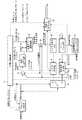
図1はこの発明の実施の形態1による動画像符号化装置を示す構成図である。
図1において、ブロック分割部1は入力画像を示す映像信号を入力すると、その入力画像を符号化制御部2により決定された符号化ブロックサイズのブロック(予測処理単位のブロック)に分割して、予測処理単位のブロックである符号化対象ブロックを出力する処理を実施する。なお、ブロック分割部1はブロック分割手段を構成している。Embodiment 1 FIG.
1 is a block diagram showing a moving picture coding apparatus according to Embodiment 1 of the present invention.
In FIG. 1, when a video signal indicating an input image is input, the block dividing unit 1 divides the input image into blocks having a coding block size determined by the coding control unit 2 (blocks of prediction processing units), A process of outputting an encoding target block that is a block of a prediction processing unit is performed. The block dividing unit 1 constitutes a block dividing unit.
符号化制御部2は符号化対象ブロックのサイズである符号化ブロックサイズを決定するとともに、選択可能な1以上のイントラ符号化モード及びインター符号化モードの中から、ブロック分割部1から出力される符号化対象ブロックに対する符号化効率が最も高い符号化モードを決定する処理を実施する。
また、符号化制御部2は符号化効率が最も高い符号化モードがイントラ符号化モードである場合、そのイントラ符号化モードで符号化対象ブロックに対するイントラ予測処理を実施する際に用いるイントラ予測パラメータを決定し、符号化効率が最も高い符号化モードがインター符号化モードである場合、そのインター符号化モードで符号化対象ブロックに対するインター予測処理を実施する際に用いるインター予測パラメータを決定する処理を実施する。The
In addition, when the coding mode having the highest coding efficiency is the intra coding mode, the
ただし、符号化制御部2は符号化効率が最も高い符号化モードがインター符号化モードである場合、符号化ブロックサイズが所定サイズ以下であれば、符号化対象ブロックに属する全てのパーティションに対して、共通のインター予測モードと共通の参照画像指示インデックスを決定して、そのインター予測モード及び参照画像指示インデックスを含むインター予測パラメータを動き補償予測部5及び可変長符号化部13に出力する処理を実施する。
さらに、符号化制御部2は変換・量子化部7、逆量子化・逆変換部8及び可変長符号化部13に与える予測差分符号化パラメータを決定する処理を実施する。
なお、符号化制御部2は符号化制御手段を構成している。However, when the encoding mode having the highest encoding efficiency is the inter encoding mode, the
Furthermore, the
The
切換スイッチ3は符号化制御部2により決定された符号化モードがイントラ符号化モードであれば、ブロック分割部1から出力された符号化対象ブロックをイントラ予測部4に出力し、符号化制御部2により決定された符号化モードがインター符号化モードであれば、ブロック分割部1から出力された符号化対象ブロックを動き補償予測部5に出力する処理を実施する。
イントラ予測部4はイントラ予測用メモリ10に格納されている局所復号画像を参照しながら、符号化制御部2により決定されたイントラ予測パラメータを用いて、切換スイッチ3から出力された符号化対象ブロックに対するイントラ予測処理を実施してイントラ予測画像を生成する処理を実施する。If the coding mode determined by the
The
動き補償予測部5は切換スイッチ3から出力された符号化対象ブロックと動き補償予測フレームメモリ12に格納されているフィルタリング処理後の局所復号画像を比較して動きベクトルを探索し、その動きベクトルと符号化制御部2により決定されたインター予測パラメータを用いて、その符号化対象ブロックに対するインター予測処理(動き補償予測処理)を実施してインター予測画像(予測画像)を生成する処理を実施する。
ただし、動き補償予測部5は符号化制御部2により符号化対象ブロックに属する全てのパーティションに対して、共通のインター予測モードと共通の参照画像指示インデックスが決定された場合、その参照画像指示インデックスが示す全てのパーティションで共通の参照画像と、符号化対象ブロックに属する各々のパーティションとを比較して、パーティション毎に動きベクトルを探索し、その動きベクトルと上記インター予測パラメータを用いて、当該パーティションに対するインター予測処理を実施することで予測画像を生成するとともに、その動きベクトルを可変長符号化部13に出力する処理を実施する。
なお、動き補償予測部5は予測画像生成手段を構成している。The motion compensated
However, if the common inter prediction mode and the common reference image indication index are determined for all partitions belonging to the encoding target block by the
The motion
減算部6はブロック分割部1より出力された符号化対象ブロックから、イントラ予測部4により生成されたイントラ予測画像、または、動き補償予測部5により生成されたインター予測画像を減算して、その減算結果である予測差分信号(差分画像)を変換・量子化部7に出力する処理を実施する。
変換・量子化部7は符号化制御部2により決定された予測差分符号化パラメータを参照して、減算部6から出力された予測差分信号に対する直交変換処理(例えば、DCT(離散コサイン変換)や、予め特定の学習系列に対して基底設計がなされているKL変換等の直交変換処理)を実施して変換係数を算出するとともに、その予測差分符号化パラメータを参照して、その変換係数を量子化し、量子化後の変換係数である圧縮データ(差分画像の量子化係数)を逆量子化・逆変換部8及び可変長符号化部13に出力する処理を実施する。
なお、減算部6及び変換・量子化部7から量子化手段が構成されている。The subtraction unit 6 subtracts the intra prediction image generated by the
The transform /
The subtracting unit 6 and the transform /
逆量子化・逆変換部8は符号化制御部2により決定された予測差分符号化パラメータを参照して、変換・量子化部7から出力された圧縮データを逆量子化するとともに、その予測差分符号化パラメータを参照して、逆量子化後の圧縮データである変換係数に対する逆直交変換処理を実施して、減算部6から出力された予測差分信号に相当する局所復号予測差分信号を算出する処理を実施する。
加算部9は逆量子化・逆変換部8により算出された局所復号予測差分信号と、イントラ予測部4により生成されたイントラ予測画像、または、動き補償予測部5により生成されたインター予測画像とを加算して、ブロック分割部1から出力された符号化対象ブロックに相当する局所復号画像を算出する処理を実施する。The inverse quantization /
The
イントラ予測用メモリ10は加算部9により算出された局所復号画像を格納する記録媒体である。
ループフィルタ部11は加算部9により算出された局所復号画像に対して、所定のフィルタリング処理を実施して、フィルタリング処理後の局所復号画像を出力する処理を実施する。
動き補償予測フレームメモリ12はフィルタリング処理後の局所復号画像を格納する記録媒体である。The intra prediction memory 10 is a recording medium that stores the locally decoded image calculated by the adding
The loop filter unit 11 performs a predetermined filtering process on the local decoded image calculated by the adding
The motion compensated
可変長符号化部13は変換・量子化部7から出力された圧縮データと、符号化制御部2の出力信号(符号化モード、イントラ予測パラメータ又はインター予測パラメータ、予測差分符号化パラメータ)と、動き補償予測部5から出力された動きベクトル(符号化モードがインター符号化モードである場合)とを可変長符号化してビットストリームを生成する処理を実施する。
なお、可変長符号化部13は可変長符号化手段を構成している。The variable
The variable
図1の例では、動画像符号化装置の構成要素であるブロック分割部1、符号化制御部2、切換スイッチ3、イントラ予測部4、動き補償予測部5、減算部6、変換・量子化部7、逆量子化・逆変換部8、加算部9、イントラ予測用メモリ10、ループフィルタ部11、動き補償予測フレームメモリ12及び可変長符号化部13のそれぞれが専用のハードウェア(例えば、CPUを実装している半導体集積回路や、ワンチップマイコンなど)で構成されているものを想定しているが、動画像符号化装置がコンピュータで構成される場合、ブロック分割部1、符号化制御部2、切換スイッチ3、イントラ予測部4、動き補償予測部5、減算部6、変換・量子化部7、逆量子化・逆変換部8、加算部9、ループフィルタ部11及び可変長符号化部13の処理内容を記述しているプログラムをコンピュータのメモリに格納し、当該コンピュータのCPUが当該メモリに格納されているプログラムを実行するようにしてもよい。
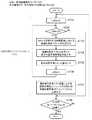
図3はこの発明の実施の形態1による動画像符号化装置の処理内容(動画像符号化方法)を示すフローチャートである。In the example of FIG. 1, a block division unit 1, an
FIG. 3 is a flowchart showing the processing contents (moving image coding method) of the moving image coding apparatus according to Embodiment 1 of the present invention.
図2はこの発明の実施の形態1による動画像符号化装置の動き補償予測部5の内部を示す構成図である。
図2において、動きベクトル探索部21は切換スイッチ3から出力された符号化対象ブロックと動き補償予測フレームメモリ12に格納されている1フレーム以上の参照画像を参照しながら、インター符号化モードで最適な動きベクトルを探索し、その動きベクトルを動き補償処理部22に出力する処理を実施する。
ただし、動きベクトル探索部21は符号化制御部2により符号化対象ブロックに属する全てのパーティションに対して、共通のインター予測モードと共通の参照画像指示インデックスが決定された場合、その参照画像指示インデックスが示す全てのパーティションで共通の参照画像と、符号化対象ブロックに属する各々のパーティションとを比較して、パーティション毎に動きベクトルを探索し、その動きベクトルを動き補償処理部22及び可変長符号化部13に出力する。FIG. 2 is a block diagram showing the inside of the motion
In FIG. 2, the motion
However, when the common inter prediction mode and the common reference image instruction index are determined for all partitions belonging to the encoding target block by the
動き補償処理部22は動きベクトル探索部21により探索された動きベクトルと動き補償予測フレームメモリ12に格納されている1フレーム以上の参照画像を用いて、符号化制御部2から出力されたインター予測パラメータに基づいてインター予測処理(動き補償予測処理)を実施することで、インター予測画像を生成する処理を実施する。
ただし、動き補償処理部22は符号化制御部2により符号化対象ブロックに属する全てのパーティションに対して、共通のインター予測モードと共通の参照画像指示インデックスが決定された場合、動きベクトル探索部21により探索された動きベクトルと参照画像指示インデックスが示す全てのパーティションで共通の参照画像を用いて、符号化制御部2から出力されたインター予測パラメータに基づいて、当該パーティションに対するインター予測処理を実施することで、インター予測画像を生成する処理を実施する。The motion
However, when the
図10はこの発明の実施の形態1による動画像復号装置を示す構成図である。
図10において、可変長復号部31は図1の動画像符号化装置により生成されたビットストリームを入力すると、そのビットストリームに多重化されている符号化データから予測処理単位のブロックである復号対象ブロック(符号化対象ブロック)に係る圧縮データ、符号化モード、イントラ予測パラメータ(符号化モードがイントラ符号化モードである場合)、インター予測パラメータ(符号化モードがインター符号化モードである場合)、予測差分符号化パラメータ及び動きベクトル(符号化モードがインター符号化モードである場合)を可変長復号する処理を実施する。
なお、可変長復号部31は符号化対象ブロックに属する全てのパーティションに対して、共通のインター予測モードと共通の参照画像指示インデックスが決定されている場合、共通のインター予測モードと共通の参照画像指示インデックスを含んでいるインター予測パラメータを可変長復号するとともに、符号化対象ブロックに属するパーティション毎の動きベクトルを可変長復号する。
可変長復号部31は可変長復号手段を構成している。FIG. 10 is a block diagram showing a moving picture decoding apparatus according to Embodiment 1 of the present invention.
In FIG. 10, when the variable
Note that the variable-
The variable
逆量子化・逆変換部32は可変長復号部31により可変長復号された予測差分符号化パラメータを参照して、可変長復号部31により可変長復号された圧縮データを逆量子化するとともに、その予測差分符号化パラメータを参照して、逆量子化後の圧縮データである変換係数に対する逆直交変換処理を実施して、復号予測差分信号を算出する処理を実施する。なお、逆量子化・逆変換部32は逆量子化手段を構成している。 The inverse quantization /
切換スイッチ33は可変長復号部31により可変長復号された符号化モードがイントラ符号化モードであれば、可変長復号部31により可変長復号されたイントラ予測パラメータをイントラ予測部34に出力し、可変長復号部31により可変長復号された符号化モードがインター符号化モードであれば、可変長復号部31により可変長復号されたインター予測パラメータ及び動きベクトルを動き補償部35に出力する処理を実施する。
イントラ予測部34はイントラ予測用メモリ37に格納されている復号画像を参照しながら、切換スイッチ33から出力されたイントラ予測パラメータを用いて、復号対象ブロックに対するイントラ予測処理を実施してイントラ予測画像を生成する処理を実施する。The
The
動き補償部35は動き補償予測フレームメモリ39に格納されているフィルタリング処理後の復号画像を参照しながら、切換スイッチ33から出力された動きベクトルとインター予測パラメータを用いて、復号対象ブロックに対するインター予測処理(動き補償予測処理)を実施してインター予測画像(予測画像)を生成する処理を実施する。
ただし、動き補償部35は復号対象ブロックに属する全てのパーティションに対して、共通のインター予測モードと共通の参照画像指示インデックスが決定されている場合、その参照画像指示インデックスが示す全てのパーティションで共通の参照画像と、パーティション毎の動きベクトルとを用いて、当該パーティションに対するイントラ予測処理を実施してイントラ予測画像を生成する処理を実施する。
なお、動き補償部35は予測画像生成手段を構成している。The
However, when a common inter prediction mode and a common reference image instruction index are determined for all partitions belonging to the decoding target block, the
The
加算部36は逆量子化・逆変換部32により算出された復号予測差分信号と、イントラ予測部34により生成されたイントラ予測画像、または、動き補償部35により生成されたインター予測画像とを加算して、復号画像を算出する処理を実施する。
イントラ予測用メモリ37は加算部36により算出された復号画像を格納する記録媒体である。
ループフィルタ部38は加算部36により算出された復号画像に対して、所定のフィルタリング処理を実施して、フィルタリング処理後の復号画像を出力する処理を実施する。
動き補償予測フレームメモリ39はフィルタリング処理後の復号画像を格納する記録媒体である。The
The intra prediction memory 37 is a recording medium that stores the decoded image calculated by the
The
The motion compensated
図10の例では、動画像復号装置の構成要素である可変長復号部31、逆量子化・逆変換部32、切換スイッチ33、イントラ予測部34、動き補償部35、加算部36、イントラ予測用メモリ37、ループフィルタ部38及び動き補償予測フレームメモリ39のそれぞれが専用のハードウェア(例えば、CPUを実装している半導体集積回路や、ワンチップマイコンなど)で構成されているものを想定しているが、動画像復号装置がコンピュータで構成される場合、可変長復号部31、逆量子化・逆変換部32、切換スイッチ33、イントラ予測部34、動き補償部35、加算部36及びループフィルタ部38の処理内容を記述しているプログラムをコンピュータのメモリに格納し、当該コンピュータのCPUが当該メモリに格納されているプログラムを実行するようにしてもよい。
図11はこの発明の実施の形態1による動画像復号装置の処理内容(動画像復号方法)を示すフローチャートである。In the example of FIG. 10, the variable
FIG. 11 is a flowchart showing the processing contents (moving image decoding method) of the moving image decoding apparatus according to Embodiment 1 of the present invention.
次に動作について説明する。
この実施の形態1では、映像の各フレーム画像を入力画像として、近接フレーム間で動き補償予測を実施して、得られた予測差分信号に対して直交変換・量子化による圧縮処理を施し、その後、可変長符号化を行ってビットストリームを生成する動画像符号化装置と、その動画像符号化装置から出力されるビットストリームを復号する動画像復号装置について説明する。Next, the operation will be described.
In the first embodiment, each frame image of a video is used as an input image, motion compensation prediction is performed between adjacent frames, and the obtained prediction difference signal is subjected to compression processing by orthogonal transformation / quantization, and then A moving picture coding apparatus that performs variable length coding to generate a bit stream and a moving picture decoding apparatus that decodes a bit stream output from the moving picture coding apparatus will be described.
図1の動画像符号化装置は、映像信号の空間・時間方向の局所的な変化に適応して、映像信号を多様なサイズのブロックに分割して、フレーム内・フレーム間適応符号化を行うことを特徴としている。
一般的に、映像信号は、空間・時間的に信号の複雑さが局所的に変化する特性を有している。空間的に見ると、ある映像フレーム上では、例えば、空や壁などのような比較的広い画像領域中で均一な信号特性を有する絵柄もあれば、人物や細かいテクスチャを含む絵画など、小さい画像領域内で複雑なテクスチャパターンを有する絵柄も混在することがある。
時間的に見ても、空や壁は局所的に時間方向の絵柄の変化は小さいが、動く人物や物体は、その輪郭が時間的に剛体・非剛体の運動をするため、時間的な変化が大きい。The moving picture coding apparatus in FIG. 1 performs intra-frame / inter-frame adaptive coding by dividing a video signal into blocks of various sizes in response to local changes in the spatial and temporal directions of the video signal. It is characterized by that.
In general, a video signal has a characteristic that the complexity of the signal changes locally in space and time. When viewed spatially, a small image, such as a picture with a uniform signal characteristic in a relatively wide image area such as the sky or a wall, or a picture containing a person or fine texture, on a video frame. A pattern having a complicated texture pattern in the region may be mixed.
Even when viewed temporally, the change in the pattern of the sky and the wall locally in the time direction is small, but because the outline of the moving person or object moves rigidly or non-rigidly in time, the temporal change Is big.
符号化処理は、時間・空間的な予測によって、信号電力やエントロピーの小さい予測差分差信号を生成して、全体の符号量を削減する処理を行うが、予測に用いるパラメータをできるだけ大きな画像信号領域に均一に適用できれば、当該パラメータの符号量を小さくすることができる。
一方、時間的・空間的に変化の大きい画像信号パターンに対して、同一の予測パラメータを大きな画像領域に適用すると、予測の誤りが増えてしまうため、予測差分信号の符号量が増加してしまう。
したがって、時間的・空間的に変化が大きい領域では、同一の予測パラメータを適用して予測処理を行うブロックサイズを小さくして、予測に用いるパラメータのデータ量を増やし、予測差分信号の電力・エントロピーを低減する方が望ましい。The encoding process generates a prediction difference difference signal with small signal power and entropy by temporal and spatial prediction, and reduces the overall code amount. If it can be applied uniformly, the code amount of the parameter can be reduced.
On the other hand, if the same prediction parameter is applied to a large image region with respect to an image signal pattern having a large temporal and spatial change, the number of prediction differential signals increases because prediction errors increase. .
Therefore, in a region where the temporal and spatial changes are large, the block size for performing the prediction process by applying the same prediction parameter is reduced, the amount of parameter data used for prediction is increased, and the power and entropy of the prediction difference signal are increased. It is desirable to reduce
この実施の形態1では、このような映像信号の一般的な性質に適応した符号化を行うため、最初に所定の最大ブロックサイズから予測処理等を開始し、階層的に映像信号の領域を分割し、分割した領域毎に予測処理や、その予測差分の符号化処理を適応化させる構成をとるようにしている。 In the first embodiment, in order to perform coding adapted to the general characteristics of such a video signal, first, prediction processing or the like is started from a predetermined maximum block size, and the video signal region is divided hierarchically. In addition, the prediction process and the encoding process of the prediction difference are adapted for each divided area.
図1の動画像符号化装置が処理対象とする映像信号フォーマットは、輝度信号と2つの色差信号からなるYUV信号や、ディジタル撮像素子から出力されるRGB信号等の任意の色空間のカラー映像信号のほか、モノクロ画像信号や赤外線画像信号など、映像フレームが水平・垂直2次元のディジタルサンプル(画素)列から構成される任意の映像信号とする。
ただし、各画素の諧調は、8ビットでもよいし、10ビットや12ビットなどの諧調でもよい。The video signal format to be processed by the moving image encoding apparatus of FIG. 1 is a color video signal in an arbitrary color space such as a YUV signal composed of a luminance signal and two color difference signals, or an RGB signal output from a digital image sensor. In addition to the above, it is assumed that the video frame is an arbitrary video signal including a horizontal / vertical two-dimensional digital sample (pixel) sequence, such as a monochrome image signal or an infrared image signal.
However, the gradation of each pixel may be 8 bits, or a gradation such as 10 bits or 12 bits.
以下の説明では、便宜上、特に断らない限り、入力画像の映像信号はYUV信号であるとし、かつ、2つの色差成分U,Vが輝度成分Yに対して、サブサンプルされた4:2:0フォーマットの信号を扱う場合について述べる。
また、映像信号の各フレームに対応する処理データ単位を「ピクチャ」と称する。
この実施の形態1では、「ピクチャ」は順次走査(プログレッシブスキャン)された映像フレーム信号として説明を行うが、映像信号がインタレース信号である場合、「ピクチャ」は映像フレームを構成する単位であるフィールド画像信号であってもよい。In the following description, for convenience, unless otherwise specified, it is assumed that the video signal of the input image is a YUV signal, and the two color difference components U and V are subsampled with respect to the luminance component Y 4: 2: 0. The case of handling format signals will be described.
A processing data unit corresponding to each frame of the video signal is referred to as a “picture”.
In the first embodiment, “picture” is described as a video frame signal that is sequentially scanned (progressive scan). However, when the video signal is an interlaced signal, “picture” is a unit constituting a video frame. It may be a field image signal.
最初に、図1の動画像符号化装置の処理内容を説明する。
まず、符号化制御部2は、符号化対象となるピクチャ(カレントピクチャ)の符号化に用いる最大符号化ブロックのサイズと、最大符号化ブロックを階層分割する階層数の上限を決定する(図3のステップST1)。
最大符号化ブロックのサイズの決め方としては、例えば、入力画像の映像信号の解像度に応じて、すべてのピクチャに対して同一のサイズを定めてもよいし、入力画像の映像信号の局所的な動きの複雑さの違いをパラメータとして定量化して、動きの激しいピクチャには、小さいサイズを定める一方、動きが少ないピクチャには、大きいサイズを定めるようにしてもよい。
分割階層数の上限の決め方としては、例えば、入力画像の映像信号の動きが激しい場合には、階層数を深くして、より細かい動きが検出できるように設定し、動きが少ない場合には、階層数を抑えるように設定するなどの方法がある。First, the processing contents of the moving picture encoding apparatus in FIG. 1 will be described.
First, the
As a method of determining the size of the maximum coding block, for example, the same size may be determined for all the pictures according to the resolution of the video signal of the input image, or the local motion of the video signal of the input image The size difference may be quantified as a parameter, and a small size may be determined for a picture with high motion, while a large size may be determined for a picture with little motion.
As an example of how to determine the upper limit of the number of division layers, for example, when the motion of the video signal of the input image is intense, set the number of layers to be deeper so that a finer motion can be detected. There are methods such as setting to suppress the number of layers.
ブロック分割部1は、入力画像の映像信号を入力すると、符号化制御部2により決定された最大符号化ブロックサイズで、入力画像のピクチャに分割し、分割後の各ピクチャを出力する。
また、符号化制御部2は、最大符号化ブロックサイズの画像領域毎に、先に定めた分割階層数の上限に至るまで、階層的に符号化ブロックサイズを有する符号化対象ブロックに分割して、各符号化対象ブロックに対する符号化モードを決定する(ステップST2)。When the video signal of the input image is input, the block dividing unit 1 divides the picture into the picture of the input image with the maximum coding block size determined by the
In addition, the
ここで、図4は最大符号化ブロックが階層的に複数の符号化対象ブロックに分割される例を示す説明図である。
図4において、最大符号化ブロックは、「第0階層」と記されている輝度成分が(L0,M0)のサイズを有する符号化対象ブロックである。
最大符号化ブロックを出発点として、4分木構造で別途定める所定の深さまで、階層的に分割を行うことによって符号化対象ブロックを得るようにしている。
深さnにおいては、符号化対象ブロックはサイズ(Ln,Mn)の画像領域である。
ただし、LnとMnは、同じであってもよいし、異なっていてもよいが、図4では、Ln=Mnのケースを示している。Here, FIG. 4 is an explanatory diagram showing an example in which the maximum coding block is hierarchically divided into a plurality of coding target blocks.
In FIG. 4, the maximum coding block is a coding target block whose luminance component indicated as “0th layer” has a size of (L0 , M0 ).
The encoding target block is obtained by hierarchically dividing the maximum encoding block as a starting point to a predetermined depth separately defined by a quadtree structure.
At the depth n, the encoding target block is an image area of size (Ln , Mn ).
However, Ln and Mn may be the same or different, but FIG. 4 shows a casewhere Ln = Mn .
以降、符号化制御部2により決定される符号化ブロックサイズは、符号化対象ブロックの輝度成分におけるサイズ(Ln,Mn)と定義する。
4分木分割を行うため、常に、(Ln+1,Mn+1)=(Ln/2,Mn/2)が成立する。
なお、RGB信号など、全ての色成分が同一サンプル数を有するカラー映像信号(4:4:4フォーマット)では、全ての色成分のサイズが(Ln,Mn)になるが、4:2:0フォーマットを扱う場合、対応する色差成分の符号化ブロックサイズは(Ln/2,Mn/2)になる。Hereinafter, the encoding block size determined by the
Since quadtree partitioning is performed, (Ln + 1 , Mn + 1 ) = (Ln / 2, Mn / 2) always holds.
In a color video signal (4: 4: 4 format) in which all color components have the same number of samples, such as RGB signals, the size of all color components is (Ln , Mn ), but 4: 2. : 0 when working with formatting, coding block size of the corresponding color difference component becomes(L n / 2, M n / 2).
以降、第n階層の符号化対象ブロックをBnで表し、符号化対象ブロックBnで選択可能な符号化モードをm(Bn)で表すものとする。
複数の色成分からなるカラー映像信号の場合、符号化モードm(Bn)は、色成分毎に、それぞれ個別のモードを用いるように構成されてもよいし、すべての色成分に対し共通のモードを用いるように構成されてもよい。以降、特に断らない限り、YUV信号、4:2:0フォーマットの符号化ブロックの輝度成分に対する符号化モードを指すものとして説明を行う。Later, represents the encoding target block of the n hierarchy Bn, the encoding modes selectable by the encoding target block Bn as represented by m (Bn).
In the case of a color video signal composed of a plurality of color components, the encoding mode m (Bn ) may be configured to use an individual mode for each color component, or common to all color components. It may be configured to use a mode. Hereinafter, unless otherwise specified, description will be made assuming that it indicates a coding mode for a luminance component of a coding block of a YUV signal and 4: 2: 0 format.
符号化モードm(Bn)には、1つないし複数のイントラ符号化モード(総称して「INTRA」と称する)と、1つないし複数のインター符号化モード(総称して、「INTER」と称する)とがあり、符号化制御部2は、当該ピクチャで利用可能な全ての符号化モード、または、そのサブセットの中から、符号化対象ブロックBnに対する符号化効率が最も高い符号化モードを選択する。The encoding mode m (Bn ) includes one or more intra encoding modes (collectively referred to as “INTRA”), one or more inter encoding modes (collectively referred to as “INTER”), The
さらに、符号化対象ブロックBnは、図4に示すように、ブロック分割部1によって、1つないし複数の予測処理単位(パーティション)に分割される。
以降、符号化対象ブロックBnに属するパーティションをPin(iは、第n階層におけるパーティション番号)と表記する。
符号化対象ブロックBnのパーティション分割が、どのようになされているかは、符号化モードm(Bn)の中に情報として含まれる。
パーティションPinは、すべて符号化モードm(Bn)に従って予測処理が行われるが、符号化対象ブロックBnないしパーティションPin毎に、予測パラメータが選択される。Further, the encoding target block Bn is divided into one or a plurality of prediction processing units (partitions) by the block dividing unit 1 as shown in FIG.
Hereinafter, a partition belonging to the encoding target block Bn isdenoted as Pin (i is a partition number in the nth layer).
How the partitioning of the encoding target block Bn is performed is included as information in the encoding mode m (Bn ).
All the partitions Pin are subjected to prediction processing according to the encoding mode m (Bn ), but a prediction parameter is selected for each encoding target block Bn or partition Pin .
符号化制御部2は、最大符号化ブロックに対して、例えば、図5に示すようなブロック分割状態を生成して、符号化対象ブロックを特定する。
図5(a)の斜線部分は、分割後のパーティションの分布を示しており、図5(b)は階層分割によって符号化モードm(Bn)が割り当てられる状況を4分木グラフで示している。
図5(b)の□で囲まれているノードは、符号化モードm(Bn)が割り当てられたノード(符号化対象ブロック)である。
符号化制御部2における階層分割・符号化モード判定の詳細な処理は後述する。For example, the
The shaded area in FIG. 5 (a) shows the distribution of the partitions after the division, and FIG. 5 (b) shows the situation where the encoding mode m (Bn ) is assigned by the hierarchical division in a quadtree graph. Yes.
Nodes surrounded by □ in FIG. 5B are nodes (encoding target blocks) to which the encoding mode m (Bn ) is assigned.
Detailed processing of layer division / encoding mode determination in the
切換スイッチ3は、符号化制御部2により決定された符号化モードm(Bn)がイントラ符号化モードである場合(m(Bn)∈INTRAの場合)、ブロック分割部1から出力された符号化対象ブロックBnをイントラ予測部4に出力する。
一方、符号化制御部2により決定された符号化モードm(Bn)がインター符号化モードである場合(m(Bn)∈INTERの場合)、ブロック分割部1から出力された符号化対象ブロックBnを動き補償予測部5に出力する。The changeover switch 3 is output from the block dividing unit 1 when the coding mode m (Bn ) determined by the
On the other hand, when the encoding mode m (Bn ) determined by the
イントラ予測部4は、符号化制御部2により決定された符号化モードm(Bn)がイントラ符号化モードであり(m(Bn)∈INTRAの場合)、切換スイッチ3から符号化対象ブロックBnを受けると(ステップST3)、イントラ予測用メモリ10に格納されている局所復号画像を参照しながら、符号化制御部2により決定されたイントラ予測パラメータを用いて、その符号化対象ブロックBn内の各パーティションPinに対するイントラ予測処理を実施して、イントラ予測画像PINTRAinを生成する(ステップST4)。
なお、画像復号装置がイントラ予測画像PINTRAinと全く同じイントラ予測画像を生成する必要があるため、イントラ予測画像PINTRAinの生成に用いられたイントラ予測パラメータは、符号化制御部2から可変長符号化部13に出力されて、ビットストリームに多重化される。The
Since the image decoding apparatus needs to generate exactly the same intra prediction image and the intra prediction image PINTRAin, intra prediction parameters used for generating the intra prediction image PINTRAin is a variable from the
動き補償予測部5は、符号化制御部2により決定された符号化モードm(Bn)がインター符号化モードであり(m(Bn)∈INTERの場合)、切換スイッチ3から符号化対象ブロックBnを受けると(ステップST3)、その符号化対象ブロックBn内の各パーティションPinと動き補償予測フレームメモリ12に格納されているフィルタリング処理後の局所復号画像を比較して動きベクトルを探索し、その動きベクトルと符号化制御部2により決定されたインター予測パラメータを用いて、その符号化対象ブロックBn内の各パーティションPinに対するインター予測処理を実施して、インター予測画像PINTERinを生成する(ステップST5)。
動き補償予測部5の具体的な処理内容は後述する。The motion compensated
Specific processing contents of the motion
なお、図10の動画像復号装置がインター予測画像PINTERinと全く同じインター予測画像を生成する必要があるため、インター予測画像PINTERinの生成に用いられたインター予測パラメータは、符号化制御部2から可変長符号化部13に出力されて、ビットストリームに多重化される。
インター予測画像の生成に用いられたインター予測パラメータには、下記の情報が含まれている。
(1)パーティションPinに空間方向または時間方向に隣接する1以上のパーティションのいずれか1つのパーティションのインター予測モード指示情報と参照画像指示インデックス情報および動きベクトルをパーティションPinに対して適用するかどうかを示すフラグ(マージフラグ)
(2)マージフラグが1の場合(隣接するパーティションのインター予測モード指示情報と参照画像指示インデックス情報及び動きベクトルを用いて、パーティションPinのインター予測画像を生成する場合)に、空間方向または時間方向に隣接する1以上のパーティションの中から、どのパーティションのインター予測モード指示情報と参照画像指示インデックス情報及び動きベクトルを適用するかを指示するインデックス(マージインデックス)
マージフラグが1ではない場合には、インター予測パラメータには以下の(3)から(5)の情報が含まれる。
(3)動き補償予測フレームメモリ12内に含まれている複数の参照画像のうち、1フレームの参照画像と、1つの動きベクトルとを用いて生成される予測画像をインター予測画像PINTERinとするか(単一予測モード)、あるいは、2フレームの参照画像と、それぞれの参照画像に対して1つの動きベクトルとを用いて生成される2つの予測画像を補間して生成される補間画像をインター予測画像PINTERinとするか(双予測モード)を示すインター予測モード指示情報
(4)動き補償予測フレームメモリ12内に2フレーム以上の参照画像を含む構成の場合、予測画像の生成に用いた参照画像を示す参照画像指示インデックス情報
(5)複数の動きベクトルの予測値候補がある場合に、いずれの動きベクトルの予測値を選択して使用するかを示すインデックス情報Incidentally, since it is necessary to video decoding apparatus of FIG. 10 to generate an identical inter prediction image and the inter-predicted image PINTERin, inter prediction parameters used for generating the inter prediction image PINTERin, the encoding control The data is output from the
The inter prediction parameters used for generating the inter prediction image include the following information.
(1) Inter prediction mode instruction information, reference image instruction index information, and motion vector of any one of one or more partitions adjacent to the partition Pin in the spatial direction or the temporal direction are applied to the partition Pin Flag indicating whether to perform (merge flag)
(2) When the merge flag is 1 (when the inter prediction image of the partition Pin is generated using the inter prediction mode instruction information of the adjacent partition, the reference image instruction index information, and the motion vector), An index (merge index) indicating which partition's inter prediction mode instruction information, reference image instruction index information, and motion vector are applied from among one or more partitions adjacent in the time direction
When the merge flag is not 1, the inter prediction parameters include the following information (3) to (5).
(3) among the plurality of reference images contained in the motion compensated
減算部6は、ブロック分割部1から符号化対象ブロックBnを受けると、その符号化対象ブロックBn内のパーティションPinから、イントラ予測部4により生成されたイントラ予測画像PINTRAin、または、動き補償予測部5により生成されたインター予測画像PINTERinを減算して、その減算結果である予測差分信号einを変換・量子化部7に出力する(ステップST6)。Subtraction unit 6, upon receiving the encoding target block Bn from the block dividing unit 1 from its partition Pin in the encoding target block Bn, the intra prediction image PINTRAin generated by the
変換・量子化部7は、減算部6から予測差分信号einを受けると、符号化制御部2により決定された予測差分符号化パラメータを参照して、その予測差分信号einに対する直交変換処理(例えば、DCT(離散コサイン変換)や、予め特定の学習系列に対して基底設計がなされているKL変換等の直交変換処理)を実施して、その変換係数を算出する。
また、変換・量子化部7は、その予測差分符号化パラメータを参照して、その変換係数を量子化し、量子化後の変換係数である圧縮データを逆量子化・逆変換部8及び可変長符号化部13に出力する(ステップST7)。Upon receiving the prediction difference signal ein from the subtraction unit 6, the transform /
In addition, the transform /
逆量子化・逆変換部8は、変換・量子化部7から圧縮データを受けると、符号化制御部2により決定された予測差分符号化パラメータを参照して、その圧縮データを逆量子化する。
また、逆量子化・逆変換部8は、その予測差分符号化パラメータを参照して、逆量子化後の圧縮データである変換係数に対する逆直交変換処理(例えば、逆DCT、逆KL変換など)を実施して、減算部6から出力された予測差分信号einに相当する局所復号予測差分信号を算出する(ステップST8)。When receiving the compressed data from the transform /
The inverse quantization /
加算部9は、逆量子化・逆変換部8から局所復号予測差分信号を受けると、その局所復号予測差分信号と、イントラ予測部4により生成されたイントラ予測画像PINTRAin、または、動き補償予測部5により生成されたインター予測画像PINTERinとを加算して、局所復号パーティション画像、あるいは、その局所復号パーティション画像の集まりとして、ブロック分割部1から出力された符号化対象ブロックBnに相当する局所復号画像を算出する(ステップST9)。
なお、加算部9は、その局所復号画像をループフィルタ部11に出力するとともに、その局所復号画像をイントラ予測用メモリ10に格納する。
この局所復号画像が、以降のイントラ予測用の画像信号になる。Adding
The adding
This locally decoded image becomes an image signal for subsequent intra prediction.
ループフィルタ部11は、加算部9から局所復号画像を受けると、その局所復号画像に対して、所定のフィルタリング処理を実施して、フィルタリング処理後の局所復号画像を動き補償予測フレームメモリ12に格納する(ステップST10)。
なお、ループフィルタ部11によるフィルタリング処理は、入力される局所復号画像の最大符号化ブロック、あるいは、個々の符号化ブロック単位で行ってもよいし、1画面分のマクロブロックに相当する局所復号画像が入力された後に1画面分まとめて行ってもよい。When the loop filter unit 11 receives the local decoded image from the adding
Note that the filtering process by the loop filter unit 11 may be performed in the maximum encoded block of the input local decoded image or in units of individual encoded blocks, or the local decoded image corresponding to a macroblock for one screen. It may be performed for one screen after the input.
可変長符号化部13は、全ての符号化対象ブロックBnに対するステップST3〜ST9の処理が完了すると(ステップST11、ST12)、変換・量子化部7から出力された圧縮データと、符号化制御部2から出力された符号化モードm(Bn)と、符号化制御部2から出力されたイントラ予測パラメータ(符号化モードがイントラ符号化モードである場合)又はインター予測パラメータ(符号化モードがインター符号化モードである場合)と、動き補償予測部5から出力された動きベクトル(符号化モードがインター符号化モードである場合)とを可変長符号化して、それらの符号化結果を示すビットストリームを生成する(ステップST13)。
可変長符号化部13の具体的な処理内容は後述する。Variable
Specific processing contents of the variable
次に、動き補償予測部5の処理内容を具体的に説明する。ただし、符号化制御部2により符号化対象ブロックBnに属する全てのパーティションPinに対して、共通のインター予測モードと共通の参照画像指示インデックスが決定される場合の処理内容は後述する。
動き補償予測部5は、符号化制御部2から指示されるインター予測パラメータに含まれるマージフラグが1の場合、動きベクトル探索部をスキップし、符号化制御部2から指示されるインター予測パラメータに含まれるマージインデックスが指示する隣接パーティションのインター予測モード指示情報と参照画像指示インデックス情報および動きベクトルを動き補償処理部22に出力する。
動き補償予測部5は、符号化制御部2から指示されるインター予測パラメータに含まれるマージフラグが0の場合、動き補償予測部5の動きベクトル探索部21は、インター符号化モードが選択された符号化対象ブロックBn内のパーティションPinを受けとると、そのパーティションPinと符号化制御部2から指示されるインター予測パラメータ(インター予測モードと参照画像指示インデックスの情報)に基づき、動き補償予測フレームメモリ12に格納されている1フレーム以上の参照画像を参照しながら、そのインター予測パラメータに対し最適な動きベクトルを探索し、その動きベクトルを動き補償処理部22に出力する。
ここで、符号化制御部2から指示されるインター予測パラメータに対して、最適な動きベクトルを探索する処理の一例を説明する。Next, the processing content of the motion
When the merge flag included in the inter prediction parameter instructed from the
When the merge flag included in the inter prediction parameter instructed from the
Here, an example of processing for searching for an optimal motion vector for the inter prediction parameter instructed from the
まず、予測画像の生成に用いる参照画像は、参照に用いる動きベクトル毎に、参照画像リストとして管理されている。
インター予測モードが単一予測モードを示している場合には、1つの参照画像リストが管理され、参照画像リストには、動き補償予測フレーム12に格納されている参照画像の中の1フレーム以上の参照画像に対応付けられる参照画像指示インデックスが管理されている。
例えば、参照画像リストに含まれている参照画像指示インデックスは、符号化画像に対して、時間的に近い参照画像から順番に番号付けされている。なお、参照画像リストに含まれている参照画像指示インデックスは時間的に近い順に並んでいなくてもよい。First, reference images used for generating predicted images are managed as a reference image list for each motion vector used for reference.
When the inter prediction mode indicates the single prediction mode, one reference image list is managed, and the reference image list includes one or more frames in the reference image stored in the motion compensated
For example, the reference image instruction index included in the reference image list is numbered sequentially from the reference image that is temporally closer to the encoded image. Note that the reference image instruction indexes included in the reference image list do not have to be arranged in the order of time.
インター予測モードが双予測モードを示している場合には、2つの参照画像リストが管理されている。2つの参照画像リストは、参照画像リスト0、参照画像リスト1と称される。
参照画像リスト0に含まれている参照画像指示インデックスは、例えば、符号化画像に対して、時間的に後方向にある参照画像が時間的に近い順に番号付けされて管理されている。
参照画像リスト1に含まれている参照画像指示インデックスは、例えば、符号化画像に対して、時間的に前方向にある参照画像が時間的に近い順に番号付けされて管理されている。
ただし、参照ピクチャリスト0が後方向にある参照画像を示していてもよいし、前方向にある参照画像と後方向にある参照画像を示していてもよいし、時間的に近い順に並んでいなくてもよい。参照画像リスト1に対しても同様である。
また、参照画像リスト0に含まれている参照画像指示インデックスと、参照画像リスト1に含まれている参照画像指示インデックスが同じ参照画像を示していてもよい。When the inter prediction mode indicates the bi-prediction mode, two reference image lists are managed. The two reference image lists are referred to as a
The reference image instruction index included in the
The reference image instruction index included in the reference image list 1 is managed by, for example, numbering and managing the reference images in the temporally forward direction with respect to the encoded image in the order of time.
However, the
Further, the reference image instruction index included in the
符号化制御部2から指示されるインター予測モードが単一予測モードを示している場合には、符号化制御部2から指示される参照画像指示インデックスで示される参照画像内を探索して、最適な動きベクトルを決定する。
符号化制御部2から指示されるインター予測モードが双予測モードを示している場合には、符号化制御部2から指示される参照画像リスト0の参照画像指示インデックスで示される参照画像内を探索するとともに、参照画像リスト1の参照画像指示インデックスで示される参照画像内を探索し、参照画像リスト0の参照画像に対する動きベクトル0と、参照画像リスト1の参照画像に対する動きベクトル1との最適な組み合わせを決定する。
なお、動きベクトルの探索処理自体は公知の技術であるため詳細な説明を省略する。When the inter prediction mode indicated by the
When the inter prediction mode indicated by the
Since the motion vector search process itself is a known technique, a detailed description thereof will be omitted.
動き補償予測部5の動き補償処理部22は、動きベクトル探索部21から動きベクトルを受けると、その動きベクトルと動き補償予測フレームメモリ12に格納されている1フレーム以上の参照画像を用いて、符号化制御部2から出力されるインター予測パラメータに基づいて、インター予測処理を実施することで予測画像を生成する。
インター予測モードが単一予測モードを示している場合には、符号化制御部2から指示される参照画像リストの参照画像指示インデックスで示される参照画像と、動きベクトル探索部21から出力される1つの動きベクトルとを用いて、インター予測処理を実施してインター予測画像を生成する。When the motion
When the inter prediction mode indicates the single prediction mode, the reference image indicated by the reference image indication index of the reference image list indicated by the
インター予測モードが双予測モードを示している場合には、符号化制御部2から出力される参照画像リスト0の参照画像指示インデックスで示される参照画像と、動きベクトル探索部21から出力される参照画像リスト0に対する動きベクトル0を用いて生成される予測画像0と、符号化制御部2から出力される参照画像リスト1の参照画像指示インデックスで示される参照画像と、動きベクトル探索部21から出力される参照画像リスト1に対する動きベクトル1を用いて生成される予測画像1とを補間して生成される補間画像をインター予測画像として出力する。
なお、動き補償処理部22の動き補償予測処理は公知の技術であるため詳細な説明を省略する。When the inter prediction mode indicates the bi-prediction mode, the reference image indicated by the reference image instruction index of the
Since the motion compensation prediction process of the motion
次に、符号化制御部2におけるインター予測パラメータ決定の処理内容を具体的に説明する。
まず、符号化制御部2は、各インター予測モードに対して、最適な参照画像を決定する処理を実施する。
最初に、インター予測モードが単一モードの場合について説明する。Next, the processing content of the inter prediction parameter determination in the
First, the
First, a case where the inter prediction mode is a single mode will be described.
符号化制御部2は、符号化対象ブロックの階層(n)に応じて、その符号化対象ブロックBn内のパーティションPinに対して有効な参照画像指示インデックスを決定する。
階層nが所定の階層(N)以上の符号化対象ブロックBn(n≧N)内のパーティションPin(ブロックサイズが所定のサイズより小さいパーティションPin)に対しては、全てのパーティションPinに対しマージフラグを0とし、全てのパーティションが共通の参照画像指示インデックスで示される参照画像を用いることとする。
全てのパーティションに適用される参照画像指示インデックスの有効範囲は、0からKの範囲とし、この範囲の中から、全てのパーティションに最適な参照画像指示インデックスを1つ決定する。The
For hierarchical n is predetermined layer (N) or more of the encoding target block Bn (n ≧ N) in the partition Pin (partition block size is smaller than a predetermined size Pin), all partitions merge flag to Pin is 0, and the use of a reference image in which all the partitions are indicated by common reference picture indication index.
The effective range of the reference image instruction index applied to all the partitions is set to a range from 0 to K, and one optimum reference image instruction index for all the partitions is determined from this range.
一方、階層nが所定の階層(N)より小さい符号化対象ブロックBn(n<N)内のパーティションPin(ブロックサイズが所定のサイズより大きいパーティションPin)に対しては、パーティション毎にマージフラグ0または1を指示し、マージフラグ0が指示されたパーティション毎に有効な参照画像指示インデックスの中から最適な参照画像指示インデックスを決定できるようにする。
各パーティションに適用される参照画像指示インデックスの有効範囲は、0からKの範囲とする。On the other hand, for the hierarchy n is predetermined layer (N) is smaller than the target block Bn (n <N) partitions Pin in (partition block size is larger than a predetermined size Pin), the partition The
The effective range of the reference image instruction index applied to each partition is a range from 0 to K.
所定の階層(Nの値)は、例えば、符号化制御部2で決定された分割階層数の上限に設定される。
この場合には、一番小さいサイズの符号化対象ブロック内のパーティションのみ、共通のインター予測モードと共通の参照画像指示インデックスが適用される。
別の例では、所定の階層(Nの値)を、符号化対象ブロックを複数まとめた単位であるスライス単位やフレーム単位、複数フレームをまとめたシーケンス単位に切り替えるようにし、それぞれのヘッダ情報にNの値を符号化して、ビットストリームに多重化するようにしてもよい。
また、別の例では、ビットストリームの符号化条件(解像度の上限や使う符号化ツールのセットなど)を表すプロファイルやレベル毎に定めておき、プロファイルやレベルに応じて切り替えるようにしてもよい。
この場合、プロファイルやレベルに応じて、Nの値が一意に決められるため、Nの値を符号化してビットストリームに多重化する必要がない。The predetermined hierarchy (value of N) is set to the upper limit of the number of division hierarchies determined by the
In this case, the common inter prediction mode and the common reference image indication index are applied only to the partition in the encoding target block having the smallest size.
In another example, the predetermined hierarchy (value of N) is switched to a slice unit or a frame unit that is a unit in which a plurality of encoding target blocks are grouped, and a sequence unit in which a plurality of frames are grouped. May be encoded and multiplexed into a bitstream.
In another example, a bitstream encoding condition (an upper limit of resolution, a set of encoding tools to be used, and the like) may be determined for each profile or level and switched according to the profile or level.
In this case, since the value of N is uniquely determined according to the profile and level, it is not necessary to encode the value of N and multiplex it into the bit stream.
符号化対象ブロックBn(n≧N)内の全てのパーティションPinに対して最適な参照画像指示インデックスを決定する処理について説明する。
図6は符号化対象ブロックBn(n≧N)内の全てのパーティションPinに対して最適な参照画像指示インデックスを決定する処理を示すフローチャートである。
符号化制御部2は、参照画像リスト内の有効な参照画像指示インデックス(refIdx)を動き補償予測部5に指示する(ステップST21,ST22)。A process for determining an optimal reference image instruction index for all partitions Pin in the encoding target block Bn (n ≧ N) will be described.
FIG. 6 is a flowchart showing a process for determining an optimum reference image instruction index for all partitions Pin in the encoding target block Bn (n ≧ N).
The
動き補償予測部5は、符号化制御部2から参照画像リスト内の有効な参照画像指示インデックス(refIdx)を受けると、符号化対象ブロックBnの各パーティションPinに対し、以下の処理を実施する。
即ち、動き補償予測部5は、参照画像指示インデックス(refIdx)で示される参照画像に対して、最適な動きベクトルを決定する(ステップST23)。
次に、動き補償予測部5は、参照画像指示インデックス(refIdx)で示される参照画像と最適な動きベクトルを用いて、当該パーティションPinに対する動き補償予測処理を実施することで、インター予測画像PINTERinを生成する(ステップST24)。
動き補償予測部5は、インター予測画像PINTERinを生成すると、そのインター予測画像PINTERinを用いて、パーティションPin毎に動き補償予測コストを算出する(ステップST25)。The motion
That is, the motion
Next, the motion
The motion
動き補償予測コストには、例えば、インター予測画像と原画像の画素の差分絶対値和(SAD)や、インター予測画像と原画像の画素の差分二乗和(SSE)、インター予測画像と原画像の差分信号をアダマール変換などにより直交変換して得られる変換差分信号の画素の差分絶対値和(SAD)などの予測誤差コストを用いる。
または、これらの予測誤差コストに動きベクトルや参照画像指示インデックスの符号量を加味したコストを用いてもよい。または、差分信号を変換・量子化したのち、逆量子化・逆変換して局所復号予測差分信号を生成し、インター予測画像と加算して局所復号画像を生成し、局所復号画像と原画像の差分二乗和に予測差分信号やインター予測パラメータの符号量を加味した符号量歪みコストを用いてもよい。The motion compensation prediction cost includes, for example, the sum of absolute differences (SAD) of pixels between the inter prediction image and the original image, the sum of squared differences (SSE) between pixels of the inter prediction image and the original image, and between the inter prediction image and the original image. A prediction error cost such as a sum of absolute differences (SAD) of pixels of a converted difference signal obtained by orthogonally transforming the difference signal by Hadamard transform or the like is used.
Alternatively, a cost obtained by adding the motion vector and the code amount of the reference image instruction index to these prediction error costs may be used. Alternatively, after transforming and quantizing the differential signal, a local decoded prediction differential signal is generated by inverse quantization and inverse transform, and added to the inter predicted image to generate a local decoded image, and the local decoded image and the original image are You may use the code amount distortion cost which added the code amount of the prediction difference signal and the inter prediction parameter to the difference square sum.
符号化制御部2は、符号化対象ブロックBn内の全てのパーティションPinに対して、動き補償予測部5が参照画像指示インデックス(refIdx)に対する動き補償予測コストを算出すると(ステップST26)、全てのパーティションPinの動き補償予測コストを加算して、その参照画像指示インデックス(refIdx)に対する符号化対象ブロックBnの動き補償予測コストを算出する(ステップST27)。
有効な全ての参照画像指示インデックスに対して、以上の処理(ステップST23〜ST28)を繰り返し実施する。
The above processing (steps ST23 to ST28) is repeated for all valid reference image instruction indexes.
符号化制御部2は、参照画像リスト内の有効な全ての参照画像指示インデックスに対する符号化対象ブロックBnの動き補償予測コストを算出すると(ステップST22)、それらの動き補償予測コストを比較して、最小の動き補償予測コストを特定し、動き補償予測コストが最小の参照画像指示インデックス(refIdx)を符号化対象ブロックBnの最適な参照画像指示インデックスに決定する(ステップST29)。
これにより、符号化対象ブロックBn内の全てのパーティションPinで用いられる共通の参照画像が、最適な参照画像指示インデックスで示される参照画像になる。When the
As a result, the common reference image used in all the partitions Pin in the encoding target block Bn becomes the reference image indicated by the optimal reference image instruction index.
符号化対象ブロックBn(n<N)内のパーティション毎に最適な参照画像指示インデックスを決定する処理について説明する。
図7は符号化対象ブロックBn(n<N)内のパーティション毎に最適な参照画像指示インデックスを決定する処理を示すフローチャートである。
符号化制御部2は、参照画像リスト内の有効な参照画像指示インデックス(refIdx)を動き補償予測部5に指示する(ステップST31,ST32)。Processing for determining an optimal reference image instruction index for each partition in the encoding target block Bn (n <N) will be described.
FIG. 7 is a flowchart showing processing for determining an optimal reference image instruction index for each partition in the encoding target block Bn (n <N).
The
動き補償予測部5は、符号化制御部2から参照画像リスト内の有効な参照画像指示インデックス(refIdx)を受けると、符号化対象ブロックBnの各パーティションPinに対し、以下の処理を実施する。
即ち、動き補償予測部5は、参照画像指示インデックス(refIdx)で示される参照画像に対して、最適な動きベクトルを決定する(ステップST33)。
次に、動き補償予測部5は、参照画像指示インデックス(refIdx)で示される参照画像と最適な動きベクトルを用いて、当該パーティションPinに対する動き補償予測処理を実施することで、インター予測画像PINTERinを生成する(ステップST34)。
動き補償予測部5は、インター予測画像PINTERinを生成すると、そのインター予測画像PINTERinを用いて、パーティションPin毎に動き補償予測コストを算出する(ステップST35)。パーティションPin毎に算出する動き補償予測コストは、n≧Nの場合と同様である。
有効な全ての参照画像指示インデックスに対して、以上の処理(ステップST33〜ST36)を繰り返し実施する。The motion
That is, the motion
Next, the motion
The motion
The above processing (steps ST33 to ST36) is repeated for all valid reference image instruction indexes.
符号化制御部2は、動き補償予測部5が有効な全ての参照画像指示インデックス(refIdx)に対する動き補償予測コストを算出すると、パーティションPin毎に、最小の動き補償予測コストを特定し、動き補償予測コストが最小の参照画像指示インデックス(refIdx)をパーティションPinの最適な参照画像指示インデックスに決定する(ステップST37)。
符号化対象ブロックBn内の全てのパーティションPinに対して、以上の処理(ステップST31〜ST37)を繰り返し実施して、パーティションPin毎に最適な参照画像指示インデックスを決定する(ステップST38)。
For all partitions Pin in the encoding target block Bn, and repeatedly performing the above processing (step ST31~ST37), to determine the optimal reference picture indication index for each partition Pin (step ST38).
次に、インター予測モードが双予測モードの場合について説明する。
符号化制御部2は、階層nが所定の階層(N)以上の符号化対象ブロックBn(n≧N)内のパーティションPin(ブロックサイズが所定のサイズより小さいパーティションPin)に対しては、全てのパーティションPinが、同じ参照画像リスト0の参照画像指示インデックスを適用するとともに、同じ参照画像リスト1の参照画像指示インデックスを適用する。
全てのパーティションPinに適用される参照画像リスト0の参照画像指示インデックスの有効範囲は0からK0の範囲とし、この範囲の中から、全てのパーティションPinに最適な参照画像リスト0の参照画像指示インデックスを1つ決定する。参照画像リスト1に対しても同様に、参照画像リスト1の参照画像指示インデックスの有効範囲は0からK1の範囲とし、この範囲の中から、全てのパーティションPinに最適な参照画像リスト1の参照画像指示インデックスを1つ決定する。Next, a case where the inter prediction mode is the bi-prediction mode will be described.
The effective range of the reference image indication index of the
一方、階層nが所定の階層(N)より小さい符号化対象ブロックBn(n<N)内のパーティションPin(ブロックサイズが所定のサイズより大きいパーティションPin)に対しては、パーティションPin毎に有効な参照画像指示インデックスの中から最適な参照画像指示インデックスを決定できるようにする。
各パーティションPinに適用される参照画像リスト0の参照画像指示インデックスの有効範囲は0からK0の範囲とし、参照画像リスト1の参照画像指示インデックスの有効範囲は0からK1の範囲とする。On the other hand, for the hierarchy n is predetermined layer (N) is smaller than the target block Bn (n <N) partitions Pin in (partition block size is larger than a predetermined size Pin), the partition to be able to determine the optimal reference picture indication index from among the effective reference picture indication index for each Pin.
The effective range of the reference image instruction index of the
符号化対象ブロックBn(n≧N)内の全てのパーティションPinに対して最適な参照画像指示インデックスを決定する処理について説明する。
図8は符号化対象ブロックBn(n≧N)内の全てのパーティションPinに対して最適な参照画像指示インデックスを決定する処理を示すフローチャートである。
符号化制御部2は、参照画像リスト0内の有効な参照画像指示インデックス(refIdxL0)と、参照画像リスト1内の有効な参照画像指示インデックス(refIdxL1)とを動き補償予測部5に指示する(ステップST41,ST42)。A process for determining an optimal reference image instruction index for all partitions Pin in the encoding target block Bn (n ≧ N) will be described.
FIG. 8 is a flowchart showing a process of determining an optimal reference image instruction index for all partitions Pin in the encoding target block Bn (n ≧ N).
The
動き補償予測部5は、符号化制御部2から参照画像リスト0内の有効な参照画像指示インデックス(refIdxL0)と、参照画像リスト1内の有効な参照画像指示インデックス(refIdxL1)とを受けると、参照画像リスト0の参照画像指示インデックス(refIdxL0)で示される参照画像に対する動きベクトル0と、参照画像リスト1の参照画像指示インデックス(refIdxL1)で示される参照画像に対する動きベクトル1との最適な組み合わせを決定する(ステップST43)。 When the motion
次に、動き補償予測部5は、参照画像リスト0の参照画像指示インデックス(refIdxL0)で示される参照画像と、参照画像リスト1の参照画像指示インデックス(refIdxL1)で示される参照画像と、それぞれの参照画像に対する動きベクトル0,1とを用いて、当該パーティションPinに対する動き補償予測処理を実施することで、インター予測画像PINTERinを生成する(ステップST44)。
動き補償予測部5は、インター予測画像PINTERinを生成すると、単一予測モードの場合と同様に、そのインター予測画像PINTERinを用いて、パーティションPin毎に動き補償予測コストを算出する(ステップST45)。Next, the motion
Calculating the motion
符号化制御部2は、符号化対象ブロックBn内の全てのパーティションPinに対して、動き補償予測部5が参照画像リスト0の参照画像指示インデックス(refIdxL0)に対する動き補償予測コストと、参照画像リスト1の参照画像指示インデックス(refIdxL1)に対する動き補償予測コストとを算出すると(ステップST46)、全てのパーティションPinの動き補償予測コストを加算して、参照画像リスト0の参照画像指示インデックス(refIdxL0)と参照画像リスト1の参照画像指示インデックス(refIdxL1)とに対する符号化対象ブロックBnの動き補償予測コストを算出する(ステップST47)。
参照画像リスト0内の有効な全ての参照画像指示インデックスと参照画像リスト1内の有効な全ての参照画像指示インデックスとに対して、以上の処理(ステップST43〜ST48)を繰り返し実施する。
The above processing (steps ST43 to ST48) is repeatedly performed for all valid reference image instruction indexes in the
符号化制御部2は、参照画像リスト0内の有効な全ての参照画像指示インデックスと参照画像リスト1内の有効な全ての参照画像指示インデックスとに対する符号化対象ブロックBnの動き補償予測コストを算出すると(ステップST42)、符号化対象ブロックBnの動き補償予測コストを最小とする参照画像リスト0の参照画像指示インデックス(refIdxL0)と参照画像リスト1の参照画像指示インデックス(refIdxL1)とを特定する。
そして、符号化対象ブロックBnの動き補償予測コストを最小とする参照画像リスト0の参照画像指示インデックス(refIdxL0)と参照画像リスト1の参照画像指示インデックス(refIdxL1)とを符号化対象ブロックBnの最適な参照画像指示インデックスに決定する(ステップST49)。
これにより、符号化対象ブロックBn内の全てのパーティションPinで用いられる共通の参照画像が、参照画像リスト0の最適な参照画像指示インデックスで示される参照画像と、参照画像リスト1の最適な参照画像指示インデックスで示される参照画像とになる。The
The encoding target block Bn
As a result, the common reference image used in all the partitions Pin in the encoding target block Bn is the reference image indicated by the optimal reference image instruction index in the
符号化対象ブロックBn(n<N)内のパーティションPin毎に最適な参照画像指示インデックスを決定する処理について説明する。
図9は符号化対象ブロックBn(n<N)内のパーティション毎に最適な参照画像指示インデックスを決定する処理を示すフローチャートである。
符号化制御部2は、参照画像リスト0内の有効な参照画像指示インデックス(refIdxL0)と、参照画像リスト1内の有効な参照画像指示インデックス(refIdxL1)とを動き補償予測部5に指示する(ステップST51,ST52)。The process of determining the optimal reference picture indication index for each partition Pin in the encoding target block Bn (n <N) will be described.
FIG. 9 is a flowchart showing processing for determining an optimal reference image instruction index for each partition in the encoding target block Bn (n <N).
The
動き補償予測部5は、符号化制御部2から参照画像リスト0内の有効な参照画像指示インデックス(refIdxL0)と、参照画像リスト1内の有効な参照画像指示インデックス(refIdxL1)とを受けると、参照画像リスト0の参照画像指示インデックス(refIdxL0)で示される参照画像に対する動きベクトル0と、参照画像リスト1の参照画像指示インデックス(refIdxL1)で示される参照画像に対する動きベクトル1との最適な組み合わせを決定する(ステップST53)。
次に、動き補償予測部5は、参照画像リスト0の参照画像指示インデックス(refIdxL0)で示される参照画像と、参照画像リスト1の参照画像指示インデックス(refIdxL1)で示される参照画像と、それぞれの参照画像に対する動きベクトル0,1とを用いて、当該パーティションPinに対する動き補償予測処理を実施することで、インター予測画像PINTERinを生成する(ステップST54)。When the motion
Next, the motion
動き補償予測部5は、インター予測画像PINTERinを生成すると、単一予測モードの場合と同様に、そのインター予測画像PINTERinを用いて、パーティションPin毎に動き補償予測コストを算出する(ステップST55)。パーティションPin毎に算出する動き補償予測コストは、n≧Nの場合と同様である。
参照画像リスト0内の有効な全ての参照画像指示インデックスと参照画像リスト1内の有効な全ての参照画像指示インデックスに対して、以上の処理(ステップST53〜ST56)を繰り返し実施する。Calculating the motion
The above processing (steps ST53 to ST56) is repeated for all valid reference image instruction indexes in the
符号化制御部2は、動き補償予測部5が参照画像リスト0内の有効な全ての参照画像指示インデックス(refIdxL0)に対する動き補償予測コストと、参照画像リスト1内の有効な全ての参照画像指示インデックス(refIdxL1)に対する動き補償予測コストとを算出すると、パーティションPinの動き補償予測コストを最小とする参照画像リスト0の参照画像指示インデックス(refIdxL0)と参照画像リスト1の参照画像指示インデックス(refIdxL1)とを特定する。
そして、パーティションPinの動き補償予測コストを最小とする参照画像リスト0の参照画像指示インデックス(refIdxL0)と参照画像リスト1の参照画像指示インデックス(refIdxL1)とをパーティションPinの最適な参照画像指示インデックスに決定する(ステップST57)。
符号化対象ブロックBn内の全てのパーティションPinに対して、以上の処理(ステップST51〜ST57)を繰り返し実施して、パーティションPin毎に最適な参照画像指示インデックスを決定する(ステップST58)。The
Then, the optimal reference partitions Pin in the motion compensation prediction cost reference picture indication index of the reference picture indication index (refIdxL0) and reference picture list 1
For all partitions Pin in the encoding target block Bn, and repeatedly performing the above processing (step ST51~ST57), to determine the optimal reference picture indication index for each partition Pin (step ST58).
符号化制御部2は、上記のようにして、最適な参照画像指示インデックスを決定すると、参照画像指示インデックスと同様に、階層nが所定の階層(N)以上の符号化対象ブロックBn(n≧N)内のパーティションPinに対しては、全てのパーティションPinに共通のインター予測モードを決定する。
一方、階層nが所定の階層(N)より小さい符号化対象ブロックBn(n<N)内のパーティションPinに対しては、パーティションPin毎にインター予測モードを決定する。
即ち、符号化制御部2は、符号化対象ブロックあるいはパーティション単位に、各インター予測モードに対して決定された動きベクトルと参照画像指示インデックスを用いて生成されるインター予測画像の動き補償予測コストを算出する。
そして、符号化対象ブロックあるいはパーティション単位に算出された動き補償予測コストを比較し、最小の動き補償予測コストを与えるインター予測モードを符号化対象ブロックBnあるいはパーティションPinの最適なインター予測モードに決定する。
なお、動き補償予測コストは、参照画像の決定処理と同様に、予測誤差コストに動きベクトル、参照画像指示インデックスやインター予測モードなどの符号量を加味したコストを用いる。または、参照画像の決定処理と同様に、符号量歪みコストを用いてもよい。When the
On the other hand, for the hierarchy n is within a predetermined hierarchy (N) is smaller than the target block Bn (n <N) partitions Pin, determines the inter prediction mode for each partition Pin.
That is, the
Then, the motion compensation prediction costs calculated for each encoding target block or partition are compared, and the inter prediction mode that gives the minimum motion compensation prediction cost is determined as the optimal inter prediction mode for the encoding target block Bn or partition Pin. To decide.
Note that, as the motion compensation prediction cost, a cost in which a code amount such as a motion vector, a reference image instruction index, an inter prediction mode, or the like is added to the prediction error cost is used as in the reference image determination process. Alternatively, the code amount distortion cost may be used as in the reference image determination process.
次に、可変長符号化部13が符号化制御部2から出力されたインター予測パラメータと動き補償予測部5から出力された動きベクトルを可変長符号化する処理内容を具体的に説明する。
可変長符号化部13は、階層nが所定の階層(N)以上の符号化対象ブロックBn(n≧N)については、符号化制御部2が、符号化対象ブロックBn内の全てのパーティションPinに対して、共通のインター予測モードと参照画像指示インデックスを動き補償予測部5に指示しているので、符号化対象ブロックBn毎に1つのインター予測モードと参照画像指示インデックスを含むインター予測パラメータを可変長符号化して、ビットストリームに多重化する。
動きベクトルについては、動き補償予測部5が符号化対象ブロックBn内のパーティションPin毎に生成しているので、符号化対象ブロックBn内のパーティションPin毎に動きベクトルを可変長符号化して、ビットストリームに多重化する。Next, the processing content in which the variable
For the encoding target block Bn (n ≧ N) in which the layer n is equal to or higher than the predetermined layer (N), the variable
The motion vector, since the motion
可変長符号化部13は、階層nが所定の階層(N)より小さい符号化対象ブロックBn(n<N)については、符号化制御部2が、符号化対象ブロックBn内のパーティションPin毎に1つのインター予測モードと参照画像指示インデックスを動き補償予測部5に指示しているので、符号化対象ブロックBn内のパーティションPin毎に1つのインター予測モードと参照画像指示インデックスを含むインター予測パラメータを可変長符号化して、ビットストリームに多重化する。
動きベクトルについても、動き補償予測部5が符号化対象ブロックBn内のパーティションPin毎に生成しているので、符号化対象ブロックBn内のパーティションPin毎に動きベクトルを可変長符号化して、ビットストリームに多重化する。For the encoding target block Bn (n <N) whose layer n is smaller than the predetermined layer (N), the variable
For even motion vectors, since the motion
以上で明らかなように、この実施の形態1によれば、ブロック分割部1から出力された符号化対象ブロックBnのサイズが所定サイズ以下である場合、符号化制御部2が、符号化対象ブロックBnに属する全てのパーティションPinに対して、共通のインター予測モードと共通の参照画像指示インデックスを決定して、そのインター予測モード及び参照画像指示インデックスを含むインター予測パラメータを動き補償予測部5及び可変長符号化部13に出力し、動き補償予測部5が、その参照画像指示インデックスが示す全てのパーティションPinで共通の参照画像を用いて、ブロック分割部1から出力された符号化対象ブロックBnに属するパーティションPin毎に動きベクトルを生成し、その動きベクトルを用いて、当該パーティションPinに対するインター予測処理を実施することでインター予測画像PINTERinを生成するとともに、その動きベクトルを可変長符号化部13に出力するように構成したので、符号化対象ブロックBnの中に、動きは異なるが連続している領域が含まれているような場合に、インター予測パラメータに係る情報の符号量を削減することができる効果を奏する。As apparent from the above, according to the first embodiment, when the size of the encoding target block Bn output from the block dividing unit 1 is equal to or smaller than the predetermined size, the
即ち、階層nが所定の階層(N)以上の符号化対象ブロックBn(n≧N)については、符号化制御部2が、符号化対象ブロックBn内の全てのパーティションPinに対して、共通のインター予測モードと共通の参照画像指示インデックスを動き補償予測部5に指示し、動き補償予測部5が、全てのパーティションPinで共通の参照画像を用いて、パーティションPin毎に動きベクトルを生成して、インター予測画像PINTERinを生成するようにしているので、パーティションPin毎に異なる参照画像へのメモリアクセスが不要になり、メモリアクセスを効率化することができる。
また、階層nが所定の階層(N)以上の符号化対象ブロックBn(n≧N)については、可変長符号化部13が、全てのパーティションPinで共通のインター予測モードと参照画像指示インデックスを含むインター予測パラメータを符号化対象ブロックBn毎に可変長符号化して、ビットストリームに多重化するようにしているので、インター予測パラメータに係る情報の符号量を削減することができる。That is, for the encoding target block Bn (n ≧ N) where the hierarchy n is equal to or higher than the predetermined hierarchy (N), the
For the encoding target block Bn (n ≧ N) in which the layer n is equal to or higher than the predetermined layer (N), the variable-
なお、この実施の形態1では、階層nが所定の階層(N)以上の符号化対象ブロックBn(n≧N)に対しては、全てのパーティションPinに対して共通のインター予測モードと共通の参照画像指示インデックスを適用して、そのインター予測モードと参照画像指示インデックスを含むインター予測パラメータを可変長符号化するようにしているが、全てのパーティションPinに対して、予め定められたインター予測モードと参照画像指示インデックスを適用することで、そのインター予測モードと参照画像指示インデックスを含むインター予測パラメータを符号化する必要がないようにしてもよい。
例えば、インター予測モードは、単一予測モードあるいは双予測モードのいずれか一方に固定し、参照画像指示インデックスは、固定値0に設定してもよい。また、所定の手順で、周囲の符号化済みの符号化対象ブロックから符号化対象ブロックBnの参照画像指示インデックスを推定し、その推定した値を設定するようにしてもよい。In the first embodiment, for the encoding target block Bn (n ≧ N) whose layer n is a predetermined layer (N) or higher, the common inter prediction mode is used for all the partitions Pin . applying a common reference picture indication index and, although the inter prediction parameters including a reference picture indication index and its inter-prediction mode to variable length coding, for all the partitions Pin, predetermined By applying the inter prediction mode and the reference image indication index that have been obtained, it may be unnecessary to encode the inter prediction parameter including the inter prediction mode and the reference image indication index.
For example, the inter prediction mode may be fixed to either the single prediction mode or the bi-prediction mode, and the reference image instruction index may be set to a fixed
なお、この実施の形態1では、階層nが所定の階層(N)以上の符号化対象ブロックBn(n≧N)に対しては、全てのパーティションPinのマージフラグが常に0であるとし、全てのパーティションPinに対して共通のインター予測モードと共通の参照画像指示インデックスを適用するようにしたので、階層nが所定の階層(N)以上の符号化対象ブロックBn(n≧N)に対しては、マージフラグを可変長符号化する必要がなく、マージフラグに係る情報の符号量を削減することができる。
また、階層nが所定の階層(N)以上のBn(n≧N)に対しては、マージフラグが1であることを禁止し、符号化制御部2が、符号化対象ブロックBn内の全てのパーティションPinに対して、共通のインター予測モードと共通の参照画像指示インデックスを動き補償予測部5に指示し、動き補償予測部5が、全てのパーティションPinで共通の参照画像を用いて、パーティションPin毎に動きベクトルを生成して、インター予測画像PINTERinを生成するようにしているので、パーティションPin毎に異なる参照画像へのメモリアクセスが不要になり、メモリアクセスを効率化することができる。In the first embodiment, the merge flag of all partitions Pin is always 0 for the encoding target block Bn (n ≧ N) in which the hierarchy n is a predetermined hierarchy (N) or higher. Since the common inter prediction mode and the common reference picture indication index are applied to all the partitions Pin , the encoding target block Bn (n) whose layer n is a predetermined layer (N) or higher is applied. For ≧ N), the merge flag need not be variable-length encoded, and the amount of code of information related to the merge flag can be reduced.
Further, for Bn (n ≧ N) where the hierarchy n is equal to or higher than the predetermined hierarchy (N), the merge flag is prohibited from being set to 1, and the
次に、図10の動画像復号装置の処理内容を具体的に説明する。
可変長復号部31は、図1の動画像符号化装置により生成されたビットストリームを入力すると、そのビットストリームに対する可変長復号処理を実施して(図11のステップST61)、1フレーム以上のピクチャから構成されるシーケンス単位、あるいは、ピクチャ単位にフレームサイズの情報を復号する。Next, the processing content of the moving picture decoding apparatus of FIG. 10 is demonstrated concretely.
When the variable
即ち、可変長復号部31は、図1の動画像符号化装置の符号化制御部2により決定された最大符号化ブロックサイズ及び分割階層数の上限を図1の動画像符号化装置と同様の手順で決定する(ステップST62)。
例えば、最大符号化ブロックサイズが映像信号の解像度に応じて決められた場合には、復号したフレームサイズ情報に基づいて、動画像符号化装置と同様の手順で最大符号化ブロックサイズを決定する。
最大符号化ブロックサイズ及び分割階層数の上限が、動画像符号化装置側でビットストリームに多重化された場合には、ビットストリームから復号した値を用いる。
動画像符号化装置は、図4で示されるように、最大符号化ブロックを出発点に階層的に複数の符号化対象ブロックに分割して得られる符号化対象ブロック単位に符号化モードや変換・量子化して得られる圧縮データをビットストリームに多重化する。That is, the variable
For example, when the maximum encoding block size is determined according to the resolution of the video signal, the maximum encoding block size is determined based on the decoded frame size information in the same procedure as the moving image encoding apparatus.
When the maximum encoding block size and the upper limit of the number of divided layers are multiplexed into a bit stream on the moving image encoding device side, values decoded from the bit stream are used.
As shown in FIG. 4, the moving image encoding apparatus is configured to encode an encoding mode and a conversion / conversion in units of encoding target blocks obtained by hierarchically dividing a maximum encoding block into a plurality of encoding target blocks starting from a starting point. The compressed data obtained by quantization is multiplexed into a bit stream.
可変長復号部31は、最大符号化ブロックサイズ及び分割階層数の上限を決定すると、最大符号化ブロックに割り当てられている符号化モードを復号し、その符号化モードに含まれている最大符号化ブロックの分割状態を示す情報を復号する。
そして、可変長復号部31は、最大符号化ブロックの分割状態に基づいて、階層的に分割されている復号対象ブロック(図1の動画像符号化装置の「符号化対象ブロック」に相当するブロック)を特定する(ステップST63)。When the variable
Then, the variable
次に、可変長復号部31は、復号対象ブロック(符号化対象ブロック)に割り当てられている符号化モードを復号し、その符号化モードに含まれている復号対象ブロックの分割状態を示す情報を復号する。
そして、可変長復号部31は、復号対象ブロックの分割状態に基づいて、その復号対象ブロックを更に1つないし複数の予測処理単位に分割し、符号化対象ブロック単位または予測処理単位に割り当てられている予測パラメータを復号する(ステップST64)。Next, the variable
The variable
可変長復号部31は、復号対象ブロック(符号化対象ブロック)に割り当てられている符号化モードがイントラ符号化モードである場合、その復号対象ブロックに含まれている1つ以上のパーティション毎にイントラ予測パラメータを復号する。
一方、復号対象ブロック(符号化対象ブロック)に割り当てられている符号化モードがインター符号化モードである場合、復号対象ブロック毎、あるいは、その復号対象ブロックに含まれている1つ以上のパーティション毎にインター予測パラメータを復号する。When the encoding mode assigned to the decoding target block (encoding target block) is the intra encoding mode, the variable
On the other hand, when the encoding mode assigned to the decoding target block (encoding target block) is the inter encoding mode, each decoding target block or one or more partitions included in the decoding target block Decode the inter prediction parameters.
インター予測パラメータの復号は、復号対象ブロック(符号化対象ブロック)の階層nが所定の階層(N)以上であれば、復号対象ブロック毎に、1つのインター予測モードと、各参照画像リストに1つの参照画像指示インデックスを可変長復号する。
そして、復号対象ブロック内の全てのパーティションに対して、共通のインター予測モードと共通の参照画像指示インデックスを設定する。動きベクトルについては、復号対象ブロック内のパーティション毎に可変長復号する。
一方、復号対象ブロック(符号化対象ブロック)の階層nが所定の階層(N)より小さければ、復号対象ブロック内のパーティション毎に、マージフラグを復号し、マージフラグが0の場合にはインター予測モードと、各参照画像リストに対する参照画像指示インデックスと、動きベクトルとを可変長復号する。マージフラグが1の場合には、マージインデックスを復号し、マージインデックスで示される隣接パーティションに適用されたインター予測パラメータ(インター予測モード指示情報、参照画像指示インデックス)と動きベクトルを動き補償部35に出力する。When the layer n of the decoding target block (coding target block) is equal to or higher than a predetermined layer (N), the inter prediction parameter is decoded by one inter prediction mode and one reference prediction list for each decoding target block. One reference image instruction index is variable-length decoded.
Then, a common inter prediction mode and a common reference image instruction index are set for all partitions in the decoding target block. The motion vector is subjected to variable length decoding for each partition in the decoding target block.
On the other hand, if the hierarchy n of the decoding target block (encoding target block) is smaller than the predetermined hierarchy (N), the merge flag is decoded for each partition in the decoding target block. If the merge flag is 0, the inter prediction is performed. The mode, the reference image instruction index for each reference image list, and the motion vector are subjected to variable length decoding. When the merge flag is 1, the merge index is decoded, and the inter prediction parameters (inter prediction mode instruction information, reference image instruction index) and the motion vector applied to the adjacent partition indicated by the merge index are transmitted to the
所定の階層(Nの値)は、図1の動画像符号化装置に設定されている値と同じ値が用いられる。
所定の階層(Nの値)が動画像符号化装置側で分割階層数の上限に設定されている場合には、可変長復号部31で決定された分割階層数の上限に設定される。
この場合、一番小さいサイズの復号対象ブロック(符号化対象ブロック)内のパーティションのみが、共通のインター予測モードと共通の参照画像指示インデックスが適用される。As the predetermined hierarchy (value of N), the same value as the value set in the moving picture encoding apparatus in FIG. 1 is used.
When the predetermined layer (value of N) is set to the upper limit of the number of divided layers on the video encoding device side, it is set to the upper limit of the number of divided layers determined by the variable
In this case, the common inter prediction mode and the common reference image indication index are applied only to the partition in the smallest decoding target block (encoding target block).
別の例では、動画像符号化装置側で、所定の階層(Nの値)を、符号化対象ブロックを複数まとめた単位であるスライス単位やフレーム単位、あるいは、複数のフレームをまとめたシーケンス単位に切り替えるようにし、それぞれのヘッダ情報にNの値を符号化して、ビットストリームに多重化しているような場合には、ヘッダ情報から復号した値に設定される。
また、別の例では、動画像符号化装置側で、ビットストリームの符号化条件(解像度の上限や使う符号化ツールのセットなど)を表すプロファイルやレベル毎に定められた値に設定している場合には、動画像符号化装置と同様に、プロファイルやレベル毎に定められた値に設定される。
なお、動画像符号化装置側で、符号化対象ブロックの階層nが所定の階層(N)以上の符号化対象ブロックに含まれる全てのパーティションに対し、固定のインター予測モードや参照画像指示インデックスを適用している場合には、動画像符号化装置と同様の手順で、復号対象ブロック内の全てのパーティションに対して、固定のインター予測モードや参照画像指示インデックスを設定する。In another example, on the video encoding device side, a predetermined hierarchy (value of N) is a unit of slices or frames that are a unit of a plurality of encoding target blocks, or a sequence unit of a plurality of frames. When the value of N is encoded in each header information and multiplexed in a bit stream, the value is set to a value decoded from the header information.
In another example, the video encoding device side sets a bitstream encoding condition (an upper limit of resolution, a set of encoding tools to be used, etc.) and a value determined for each level. In such a case, the value is set to a value determined for each profile or level as in the case of the moving image encoding device.
On the moving image encoding device side, a fixed inter prediction mode and a reference image instruction index are set for all partitions included in the encoding target block whose encoding target block hierarchy n is a predetermined hierarchy (N) or higher. In the case of application, a fixed inter prediction mode and a reference image instruction index are set for all partitions in the decoding target block in the same procedure as the moving picture coding apparatus.
可変長復号部31は、予測処理単位となるパーティションを、更に予測差分符号化パラメータに含まれる変換ブロックサイズの情報に基づき、変換処理単位となる1つないし複数のパーティションに分割し、変換処理単位となるパーティション毎に圧縮データ(変換・量子化後の変換係数)を復号する(ステップST64)。 The variable
切換スイッチ33は、可変長復号部31により可変長復号された符号化モードm(Bn)がイントラ符号化モードであれば(m(Bn)∈INTRAの場合)、可変長復号部31により可変長復号されたイントラ予測パラメータをイントラ予測部34に出力する。
一方、可変長復号部31により可変長復号された符号化モードm(Bn)がインター符号化モードであれば(m(Bn)∈INTERの場合)、可変長復号部31により可変長復号されたインター予測パラメータ及び動きベクトルを動き補償部35に出力する。If the encoding mode m (Bn ) variable-length decoded by the variable-
On the other hand, if the encoding mode m (Bn ) variable-length decoded by the variable-
イントラ予測部34は、可変長復号部31により可変長復号された符号化モードm(Bn)がイントラ符号化モードであり(m(Bn)∈INTRAの場合)、切換スイッチ33からイントラ予測パラメータを受けると(ステップST65)、図1のイントラ予測部4と同様の手順で、イントラ予測用メモリ37に格納されている局所復号画像を参照しながら、切換スイッチ33から出力されたイントラ予測パラメータを用いて、復号対象ブロックBn内の各パーティションPinに対するイントラ予測処理を実施して、イントラ予測画像PINTRAinを生成する(ステップST66)。The
動き補償部35は、可変長復号部31により可変長復号された符号化モードm(Bn)がインター符号化モードであり(m(Bn)∈INTERの場合)、切換スイッチ33からインター予測パラメータ及び動きベクトルを受けると(ステップST65)、動き補償予測フレームメモリ39に格納されているフィルタリング処理後の復号画像を参照しながら、切換スイッチ33から出力された動きベクトルとインター予測パラメータを用いて、復号対象ブロックBn又はパーティションPinに対するインター予測処理を実施してインター予測画像PINTERinを生成する(ステップST67)。
ただし、動き補償部35は、復号対象ブロックBn内の全てのパーティションPinに対して、共通のインター予測モードと共通の参照画像指示インデックスが決定されている場合、その参照画像指示インデックスが示す全てのパーティションPinで共通の参照画像と、パーティションPin毎の動きベクトルとを用いて、当該パーティションPinに対するイントラ予測処理を実施してイントラ予測画像PINTERinを生成する。In the
However,
逆量子化・逆変換部32は、可変長復号部31から圧縮データ及び予測差分符号化パラメータを受けると、図1の逆量子化・逆変換部8と同様の手順で、その予測差分符号化パラメータを参照して、その圧縮データを逆量子化するとともに、その予測差分符号化パラメータを参照して、逆量子化後の圧縮データである変換係数に対する逆直交変換処理を実施して、図1の減算部6から出力された予測差分信号に相当する復号予測差分信号を算出する(ステップST68)。 When receiving the compressed data and the prediction difference encoding parameter from the variable
加算部36は、逆量子化・逆変換部32により算出された復号予測差分信号と、イントラ予測部34により生成されたイントラ予測画像PINTRAin、または、動き補償部35により生成されたインター予測画像PINTERinとを加算して、復号対象ブロック内に含まれる1つないし複数の復号パーティション画像の集まりとして、復号画像をループフィルタ部38に出力するとともに、その復号画像をイントラ予測用メモリ37に格納する(ステップST69)。
この復号画像が、以降のイントラ予測用の画像信号になる。
This decoded image becomes an image signal for subsequent intra prediction.
ループフィルタ部11は、全ての復号対象ブロックBnに対するステップST63〜ST69の処理が完了すると(ステップST70)、加算部36から出力された復号画像に対して、所定のフィルタリング処理を実施して、フィルタリング処理後の復号画像を動き補償予測フレームメモリ39に格納する(ステップST71)。
この復号画像が、動き補償予測用の参照画像となり、また、再生画像となる。The loop filter unit 11, the process of step ST63~ST69 for all current block Bn is completed (step ST70), the output has been decoded image from the
This decoded image becomes a reference image for motion compensation prediction and also becomes a reproduced image.
この実施の形態1の動画像復号装置では、階層nが所定の階層(N)以上の復号対象ブロック(符号化対象ブロック)Bn(n≧N)については、可変長復号部31が、復号対象ブロックBn単位のインター予測パラメータに含まれているインター予測モードと参照画像指示インデックスを可変長復号し、復号対象ブロックBn内の全てのパーティションPinに対して、共通のインター予測モードと共通の参照画像指示インデックスを設定するようにしているので、符号量を削減して符号化されたインター予測パラメータを正しく復号することができる。
また、階層nが所定の階層(N)以上の復号対象ブロックBn(n≧N)については、全てのパーティションPinでマージフラグを0とし、動き補償部35が、全てのパーティションPinで共通の参照画像と、パーティションPin毎の動きベクトルとを用いて、インター予測画像PINTERinを生成するようにしているので、パーティションPin毎に異なる参照画像へのメモリアクセスが不要になり、メモリアクセスを効率化することができる。In the moving picture decoding apparatus according to the first embodiment, the variable
For the decoding target block Bn (n ≧ N) in which the hierarchy n is equal to or higher than the predetermined hierarchy (N), the merge flag is set to 0 in all the partitions Pin , and the
本実施の形態1では、符号化器と復号器の両方に制約をつけるものとして示したが、これはプロファイルなどで規定される、符号化器に課される制約条件として位置づけてもよい。メモリアクセスが制限されている場合などのための制約条件とすることで、性能と処理量のバランスをとることができる。 In the first embodiment, both the encoder and the decoder are shown as being constrained. However, this may be positioned as a constraint imposed on the encoder defined by a profile or the like. By using a constraint condition for cases where memory access is restricted, it is possible to balance performance and throughput.
なお、本願発明はその発明の範囲内において、実施の形態の任意の構成要素の変形、もしくは実施の形態の任意の構成要素の省略が可能である。 In the present invention, any constituent element of the embodiment can be modified or any constituent element of the embodiment can be omitted within the scope of the invention.
1 ブロック分割部(ブロック分割手段)、2 符号化制御部(符号化制御手段)、3 切換スイッチ、4 イントラ予測部、5 動き補償予測部(予測画像生成手段)、6 減算部(量子化手段)、7 変換・量子化部(量子化手段)、8 逆量子化・逆変換部、9 加算部、10 イントラ予測用メモリ、11 ループフィルタ部、12 動き補償予測フレームメモリ、13 可変長符号化部(可変長符号化手段)、21 動きベクトル探索部、22 動き補償処理部、31 可変長復号部(可変長復号手段)、32 逆量子化・逆変換部(逆量子化手段)、33 切換スイッチ、34 イントラ予測部、35 動き補償部(予測画像生成手段)、36 加算部、37 イントラ予測用メモリ、38 ループフィルタ部、39 動き補償予測フレームメモリ。 1 block dividing unit (block dividing unit), 2 encoding control unit (encoding control unit), 3 selector switch, 4 intra prediction unit, 5 motion compensation prediction unit (predicted image generation unit), 6 subtraction unit (quantization unit) ), 7 transform / quantization unit (quantization means), 8 inverse quantization / inverse transform unit, 9 addition unit, 10 intra prediction memory, 11 loop filter unit, 12 motion compensated prediction frame memory, 13 variable length coding (Variable length coding means), 21 motion vector search section, 22 motion compensation processing section, 31 variable length decoding section (variable length decoding means), 32 inverse quantization / inverse transform section (inverse quantization means), 33 switching Switch, 34 intra prediction unit, 35 motion compensation unit (predicted image generation means), 36 addition unit, 37 intra prediction memory, 38 loop filter unit, 39 motion compensated prediction frame memo .
Claims (4)
Translated fromJapanese上記符号化制御手段は、上記ブロック分割手段から出力された符号化対象ブロックのサイズが所定サイズ以下である場合、上記符号化対象ブロックに属する全てのパーティションに対して、共通のインター予測モードと共通の参照画像指示インデックスを決定して、上記インター予測モード及び上記参照画像指示インデックスを含むインター予測パラメータを上記予測画像生成手段及び上記可変長符号化手段に出力し、
上記予測画像生成手段は、上記参照画像指示インデックスが示す全てのパーティションで共通の参照画像を用いて、上記ブロック分割手段から出力された符号化対象ブロックに属するパーティション毎に動きベクトルを生成し、上記動きベクトルを用いて、当該パーティションに対するインター予測処理を実施することで予測画像を生成するとともに、上記動きベクトルを上記可変長符号化手段に出力することを特徴とする動画像符号化装置。A block dividing unit that hierarchically divides an input image into blocks of prediction processing units and outputs an encoding target block that is a block of prediction processing units, and inter prediction with respect to an encoding target block output from the block dividing unit An encoding control unit that determines an inter prediction parameter to be used when performing the process, a reference image indicated by a reference image instruction index included in the inter prediction parameter determined by the encoding control unit, and the block dividing unit. A prediction image generating means for generating a prediction image by generating a motion vector from the output encoding target block and performing an inter prediction process on the encoding target block using the motion vector; and the prediction image generation Output from the predicted image generated by the means and the block dividing means Quantization means for quantizing the difference image of the encoding target block and outputting the quantization coefficient of the difference image, the quantization coefficient output from the quantization means, and the inter prediction parameter determined by the encoding control means And a variable-length code for variable-length coding the motion vector generated by the prediction image generating means to generate a bitstream in which the quantized coefficients, the inter-prediction parameters, and the encoded data of the motion vector are multiplexed Comprising
When the size of the encoding target block output from the block dividing means is equal to or smaller than a predetermined size, the encoding control means is common to the common inter prediction mode for all partitions belonging to the encoding target block. And the inter prediction parameters including the inter prediction mode and the reference image instruction index are output to the prediction image generation unit and the variable length encoding unit,
The predicted image generation means generates a motion vector for each partition belonging to the encoding target block output from the block division means, using a reference image common to all partitions indicated by the reference image instruction index, A moving picture coding apparatus, wherein a motion picture is used to generate a predicted picture by performing inter prediction processing on the partition, and the motion vector is output to the variable length coding means.
上記可変長復号手段は、上記符号化対象ブロックに属する全てのパーティションに対して、共通のインター予測モードと共通の参照画像指示インデックスを含んでいるインター予測パラメータを可変長復号するとともに、上記符号化対象ブロックに属するパーティション毎の動きベクトルを可変長復号して、上記インター予測パラメータ及び上記動きベクトルを上記予測画像生成手段に出力し、
上記予測画像生成手段は、上記参照画像指示インデックスが示す全てのパーティションで共通の参照画像とパーティション毎の動きベクトルを用いて、当該パーティションに対するインター予測処理を実施することで予測画像を生成することを特徴とする動画像復号装置。Variable length decoding means for variable length decoding the quantized coefficients, inter prediction parameters, and motion vectors related to the block to be encoded that is a block of the prediction processing unit from the encoded data multiplexed in the bit stream, and the variable length decoding Using the reference image indicated by the reference image instruction index included in the inter prediction parameter related to the encoding target block variable-length decoded by the means and the motion vector related to the encoding target block, A prediction image generating unit that generates a prediction image by performing a prediction process, and a quantized image related to the encoding target block that has been variable-length decoded by the variable-length decoding unit, is dequantized to obtain a difference image before quantization Difference image generation means for generating the difference image generated by the difference image generation means and the difference image And a decoded image generating means for generating a decoded image by adding the predicted image generated by the measurement image generating means,
The variable length decoding means performs variable length decoding on an inter prediction parameter including a common inter prediction mode and a common reference image indication index for all partitions belonging to the encoding target block, and performs the encoding. Variable-length decoding a motion vector for each partition belonging to the target block, and outputting the inter prediction parameter and the motion vector to the prediction image generation unit;
The predicted image generation means generates a predicted image by performing inter prediction processing for the partition using a reference image common to all partitions indicated by the reference image instruction index and a motion vector for each partition. A moving image decoding apparatus.
上記符号化制御処理ステップでは、上記ブロック分割処理ステップで出力された符号化対象ブロックのサイズが所定サイズ以下である場合、上記符号化対象ブロックに属する全てのパーティションに対して、共通のインター予測モードと共通の参照画像指示インデックスを決定して、上記インター予測モード及び上記参照画像指示インデックスを含むインター予測パラメータを上記予測画像生成処理ステップ及び上記可変長符号化処理ステップに与え、
上記予測画像生成処理ステップでは、上記参照画像指示インデックスが示す全てのパーティションで共通の参照画像を用いて、上記ブロック分割処理ステップで出力された符号化対象ブロックに属するパーティション毎に動きベクトルを生成し、上記動きベクトルを用いて、当該パーティションに対するインター予測処理を実施することで予測画像を生成するとともに、上記動きベクトルを上記可変長符号化処理ステップに与えることを特徴とする動画像符号化方法。A block dividing unit hierarchically divides the input image into blocks of prediction processing units, and outputs a block to be encoded that is a block of prediction processing units; and an encoding control unit includes the block division An encoding control processing step for determining an inter prediction parameter to be used when performing the inter prediction processing on the encoding target block output in the processing step; and a prediction image generation unit configured to perform the inter prediction processing in the encoding control processing step. A motion vector is generated from the reference image indicated by the reference image instruction index included in the prediction parameter and the encoding target block output in the block division processing step, and the motion vector is used to generate the motion vector for the encoding target block. Prediction image that generates a prediction image by performing prediction processing And a quantization unit quantizes the difference image between the prediction image generated in the prediction image generation processing step and the encoding target block output in the block division processing step, and the quantization coefficient of the difference image And a variable length encoding means for outputting the quantization coefficient output in the quantization processing step, the inter prediction parameter determined in the encoding control processing step, and the predicted image generation processing step. A variable-length encoding processing step for variable-length encoding the generated motion vector to generate a bitstream in which the quantized coefficients, the inter prediction parameters, and the encoded data of the motion vector are multiplexed, and
In the encoding control processing step, when the size of the encoding target block output in the block division processing step is equal to or smaller than a predetermined size, a common inter prediction mode is used for all partitions belonging to the encoding target block. A common reference image instruction index and an inter prediction parameter including the inter prediction mode and the reference image instruction index are provided to the prediction image generation processing step and the variable length encoding processing step,
In the predicted image generation processing step, a motion vector is generated for each partition belonging to the encoding target block output in the block division processing step using a reference image common to all partitions indicated by the reference image instruction index. A moving picture coding method, wherein an inter prediction process is performed on the partition using the motion vector to generate a predicted image, and the motion vector is given to the variable length coding process step.
上記可変長復号処理ステップでは、上記符号化対象ブロックに属する全てのパーティションに対して、共通のインター予測モードと共通の参照画像指示インデックスを含んでいるインター予測パラメータを可変長復号するとともに、上記符号化対象ブロックに属するパーティション毎の動きベクトルを可変長復号して、上記インター予測パラメータ及び上記動きベクトルを上記予測画像生成処理ステップに与え、
上記予測画像生成処理ステップでは、上記参照画像指示インデックスが示す全てのパーティションで共通の参照画像とパーティション毎の動きベクトルを用いて、当該パーティションに対するインター予測処理を実施することで予測画像を生成することを特徴とする動画像復号方法。Variable length decoding means for variable length decoding processing for variable length decoding of quantized coefficients, inter prediction parameters, and motion vectors related to a block to be encoded, which is a block of a prediction processing unit, from encoded data multiplexed in a bitstream A reference image indicated by a reference image instruction index included in an inter prediction parameter associated with a coding target block that has been subjected to variable length decoding in the variable length decoding processing step, and the coding target block. Using the motion vector, the prediction image generation processing step for generating a prediction image by performing inter prediction processing on the encoding target block, and the difference image generation means are variable length decoded in the variable length decoding processing step. The quantized coefficients related to the target block to be encoded are inversely quantized to obtain a differential image before quantization. And the decoded image generation means generates the decoded image by adding the difference image generated in the difference image generation processing step and the prediction image generated in the prediction image generation processing step. And a decoded image generation processing step.
In the variable length decoding processing step, inter prediction parameters including a common inter prediction mode and a common reference image indication index are variable length decoded for all partitions belonging to the encoding target block, and the code Variable-length decoding a motion vector for each partition belonging to the block to be converted, and providing the inter prediction parameter and the motion vector to the prediction image generation processing step,
In the predicted image generation processing step, a predicted image is generated by performing inter prediction processing on the partition using a reference image common to all partitions indicated by the reference image instruction index and a motion vector for each partition. A video decoding method characterized by the above.
Priority Applications (1)
| Application Number | Priority Date | Filing Date | Title |
|---|---|---|---|
| JP2011140615AJP2013009165A (en) | 2011-06-24 | 2011-06-24 | Moving image coding device, moving image decoding device, moving image coding method, and moving image decoding method |
Applications Claiming Priority (1)
| Application Number | Priority Date | Filing Date | Title |
|---|---|---|---|
| JP2011140615AJP2013009165A (en) | 2011-06-24 | 2011-06-24 | Moving image coding device, moving image decoding device, moving image coding method, and moving image decoding method |
Publications (1)
| Publication Number | Publication Date |
|---|---|
| JP2013009165Atrue JP2013009165A (en) | 2013-01-10 |
Family
ID=47676163
Family Applications (1)
| Application Number | Title | Priority Date | Filing Date |
|---|---|---|---|
| JP2011140615APendingJP2013009165A (en) | 2011-06-24 | 2011-06-24 | Moving image coding device, moving image decoding device, moving image coding method, and moving image decoding method |
Country Status (1)
| Country | Link |
|---|---|
| JP (1) | JP2013009165A (en) |
Cited By (4)
| Publication number | Priority date | Publication date | Assignee | Title |
|---|---|---|---|---|
| CN107888917A (en)* | 2017-11-28 | 2018-04-06 | 北京奇艺世纪科技有限公司 | A kind of image coding/decoding method and device |
| JP2018164297A (en)* | 2010-09-29 | 2018-10-18 | サン パテント トラスト | Decoding method, decoding apparatus, and program |
| CN113808157A (en)* | 2021-11-18 | 2021-12-17 | 腾讯科技(深圳)有限公司 | Image processing method and device and computer equipment |
| US11310500B2 (en) | 2010-09-30 | 2022-04-19 | Sun Patent Trust | Image decoding method, image coding method, image decoding apparatus, image coding apparatus, program, and integrated circuit |
Citations (1)
| Publication number | Priority date | Publication date | Assignee | Title |
|---|---|---|---|---|
| WO2004064398A1 (en)* | 2003-01-10 | 2004-07-29 | Thomson Licensing S.A. | Fast mode decision making for interframe encoding |
- 2011
- 2011-06-24JPJP2011140615Apatent/JP2013009165A/enactivePending
Patent Citations (1)
| Publication number | Priority date | Publication date | Assignee | Title |
|---|---|---|---|---|
| WO2004064398A1 (en)* | 2003-01-10 | 2004-07-29 | Thomson Licensing S.A. | Fast mode decision making for interframe encoding |
Cited By (10)
| Publication number | Priority date | Publication date | Assignee | Title |
|---|---|---|---|---|
| JP2018164297A (en)* | 2010-09-29 | 2018-10-18 | サン パテント トラスト | Decoding method, decoding apparatus, and program |
| USRE48726E1 (en) | 2010-09-29 | 2021-09-07 | Sun Patent Trust | Image decoding method, image coding method, image decoding apparatus, image coding apparatus and integrated circuit for generating a code stream with a hierarchical code structure |
| USRE49991E1 (en) | 2010-09-29 | 2024-05-28 | Sun Patent Trust | Image decoding method, image coding method, image decoding apparatus, image coding apparatus and integrated circuit for generating a code stream with a hierarchical code structure |
| US11310500B2 (en) | 2010-09-30 | 2022-04-19 | Sun Patent Trust | Image decoding method, image coding method, image decoding apparatus, image coding apparatus, program, and integrated circuit |
| US11729389B2 (en) | 2010-09-30 | 2023-08-15 | Sun Patent Trust | Image decoding method, image coding method, image decoding apparatus, image coding apparatus, program, and integrated circuit |
| US12309371B2 (en) | 2010-09-30 | 2025-05-20 | Sun Patent Trust | Image decoding method, image coding method, image decoding apparatus, image coding apparatus, program, and integrated circuit |
| CN107888917A (en)* | 2017-11-28 | 2018-04-06 | 北京奇艺世纪科技有限公司 | A kind of image coding/decoding method and device |
| CN107888917B (en)* | 2017-11-28 | 2021-06-22 | 北京奇艺世纪科技有限公司 | Image coding and decoding method and device |
| CN113808157A (en)* | 2021-11-18 | 2021-12-17 | 腾讯科技(深圳)有限公司 | Image processing method and device and computer equipment |
| CN113808157B (en)* | 2021-11-18 | 2022-02-22 | 腾讯科技(深圳)有限公司 | Image processing method and device and computer equipment |
Similar Documents
| Publication | Publication Date | Title |
|---|---|---|
| JP6768110B2 (en) | Video decoding device and video coding device | |
| JP6381724B2 (en) | Image decoding device | |
| JP2013009165A (en) | Moving image coding device, moving image decoding device, moving image coding method, and moving image decoding method | |
| WO2014051081A1 (en) | Video encoding device, video decoding device, video encoding method, and video decoding method | |
| JP2015076781A (en) | Image encoding device, image decoding device, image encoding method, and image decoding method | |
| JP2012186762A (en) | Video encoding device, video decoding device, video encoding method, and video decoding method | |
| HK1232045A (en) | Dynamic image encoding device and method, dynamic image decoding device and method | |
| HK1232045A1 (en) | Dynamic image encoding device and method, dynamic image decoding device and method | |
| HK1186031A (en) | Dynamic image encoding device, dynamic image decoding device, dynamic image encoding method, and dynamic image decoding method | |
| HK1235953A1 (en) | Dynamic image encoding device and method, dynamic image decoding device and method | |
| HK1235953A (en) | Dynamic image encoding device and method, dynamic image decoding device and method | |
| HK1232046A (en) | Dynamic image encoding device and method, dynamic image decoding device and method | |
| HK1232046A1 (en) | Dynamic image encoding device and method, dynamic image decoding device and method | |
| HK1236065A1 (en) | Dynamic image encoding device and method, dynamic image decoding device and method | |
| HK1236065A (en) | Dynamic image encoding device and method, dynamic image decoding device and method | |
| HK1186031B (en) | Dynamic image encoding device, dynamic image decoding device, dynamic image encoding method, and dynamic image decoding method | |
| HK1232045B (en) | Dynamic image encoding device and method, dynamic image decoding device and method | |
| HK1236065B (en) | Dynamic image encoding device and method, dynamic image decoding device and method | |
| HK1235953B (en) | Dynamic image encoding device and method, dynamic image decoding device and method | |
| HK1232046B (en) | Dynamic image encoding device and method, dynamic image decoding device and method |
Legal Events
| Date | Code | Title | Description |
|---|---|---|---|
| A621 | Written request for application examination | Free format text:JAPANESE INTERMEDIATE CODE: A621 Effective date:20131205 | |
| A977 | Report on retrieval | Free format text:JAPANESE INTERMEDIATE CODE: A971007 Effective date:20141017 | |
| A131 | Notification of reasons for refusal | Free format text:JAPANESE INTERMEDIATE CODE: A131 Effective date:20141028 | |
| A521 | Written amendment | Free format text:JAPANESE INTERMEDIATE CODE: A523 Effective date:20141226 | |
| A02 | Decision of refusal | Free format text:JAPANESE INTERMEDIATE CODE: A02 Effective date:20150317 |