JP2013008004A - Imaging apparatus - Google Patents
Imaging apparatusDownload PDFInfo
- Publication number
- JP2013008004A JP2013008004AJP2012066553AJP2012066553AJP2013008004AJP 2013008004 AJP2013008004 AJP 2013008004AJP 2012066553 AJP2012066553 AJP 2012066553AJP 2012066553 AJP2012066553 AJP 2012066553AJP 2013008004 AJP2013008004 AJP 2013008004A
- Authority
- JP
- Japan
- Prior art keywords
- image
- contrast
- optical system
- display
- imaging
- Prior art date
- Legal status (The legal status is an assumption and is not a legal conclusion. Google has not performed a legal analysis and makes no representation as to the accuracy of the status listed.)
- Pending
Links
Images


Classifications
- G—PHYSICS
- G02—OPTICS
- G02B—OPTICAL ELEMENTS, SYSTEMS OR APPARATUS
- G02B7/00—Mountings, adjusting means, or light-tight connections, for optical elements
- G02B7/28—Systems for automatic generation of focusing signals
- G02B7/36—Systems for automatic generation of focusing signals using image sharpness techniques, e.g. image processing techniques for generating autofocus signals
- G02B7/365—Systems for automatic generation of focusing signals using image sharpness techniques, e.g. image processing techniques for generating autofocus signals by analysis of the spatial frequency components of the image
- G—PHYSICS
- G03—PHOTOGRAPHY; CINEMATOGRAPHY; ANALOGOUS TECHNIQUES USING WAVES OTHER THAN OPTICAL WAVES; ELECTROGRAPHY; HOLOGRAPHY
- G03B—APPARATUS OR ARRANGEMENTS FOR TAKING PHOTOGRAPHS OR FOR PROJECTING OR VIEWING THEM; APPARATUS OR ARRANGEMENTS EMPLOYING ANALOGOUS TECHNIQUES USING WAVES OTHER THAN OPTICAL WAVES; ACCESSORIES THEREFOR
- G03B13/00—Viewfinders; Focusing aids for cameras; Means for focusing for cameras; Autofocus systems for cameras
- G03B13/18—Focusing aids
- G03B13/20—Rangefinders coupled with focusing arrangements, e.g. adjustment of rangefinder automatically focusing camera
- G—PHYSICS
- G03—PHOTOGRAPHY; CINEMATOGRAPHY; ANALOGOUS TECHNIQUES USING WAVES OTHER THAN OPTICAL WAVES; ELECTROGRAPHY; HOLOGRAPHY
- G03B—APPARATUS OR ARRANGEMENTS FOR TAKING PHOTOGRAPHS OR FOR PROJECTING OR VIEWING THEM; APPARATUS OR ARRANGEMENTS EMPLOYING ANALOGOUS TECHNIQUES USING WAVES OTHER THAN OPTICAL WAVES; ACCESSORIES THEREFOR
- G03B13/00—Viewfinders; Focusing aids for cameras; Means for focusing for cameras; Autofocus systems for cameras
- G03B13/32—Means for focusing
- G03B13/34—Power focusing
- G03B13/36—Autofocus systems
- G—PHYSICS
- G03—PHOTOGRAPHY; CINEMATOGRAPHY; ANALOGOUS TECHNIQUES USING WAVES OTHER THAN OPTICAL WAVES; ELECTROGRAPHY; HOLOGRAPHY
- G03B—APPARATUS OR ARRANGEMENTS FOR TAKING PHOTOGRAPHS OR FOR PROJECTING OR VIEWING THEM; APPARATUS OR ARRANGEMENTS EMPLOYING ANALOGOUS TECHNIQUES USING WAVES OTHER THAN OPTICAL WAVES; ACCESSORIES THEREFOR
- G03B3/00—Focusing arrangements of general interest for cameras, projectors or printers
- G03B3/10—Power-operated focusing
- H—ELECTRICITY
- H04—ELECTRIC COMMUNICATION TECHNIQUE
- H04N—PICTORIAL COMMUNICATION, e.g. TELEVISION
- H04N23/00—Cameras or camera modules comprising electronic image sensors; Control thereof
- H04N23/45—Cameras or camera modules comprising electronic image sensors; Control thereof for generating image signals from two or more image sensors being of different type or operating in different modes, e.g. with a CMOS sensor for moving images in combination with a charge-coupled device [CCD] for still images
- H—ELECTRICITY
- H04—ELECTRIC COMMUNICATION TECHNIQUE
- H04N—PICTORIAL COMMUNICATION, e.g. TELEVISION
- H04N23/00—Cameras or camera modules comprising electronic image sensors; Control thereof
- H04N23/60—Control of cameras or camera modules
- H04N23/63—Control of cameras or camera modules by using electronic viewfinders
- H04N23/633—Control of cameras or camera modules by using electronic viewfinders for displaying additional information relating to control or operation of the camera
- H04N23/635—Region indicators; Field of view indicators
- H—ELECTRICITY
- H04—ELECTRIC COMMUNICATION TECHNIQUE
- H04N—PICTORIAL COMMUNICATION, e.g. TELEVISION
- H04N23/00—Cameras or camera modules comprising electronic image sensors; Control thereof
- H04N23/60—Control of cameras or camera modules
- H04N23/67—Focus control based on electronic image sensor signals
- H04N23/673—Focus control based on electronic image sensor signals based on contrast or high frequency components of image signals, e.g. hill climbing method
- H—ELECTRICITY
- H04—ELECTRIC COMMUNICATION TECHNIQUE
- H04N—PICTORIAL COMMUNICATION, e.g. TELEVISION
- H04N23/00—Cameras or camera modules comprising electronic image sensors; Control thereof
- H04N23/90—Arrangement of cameras or camera modules, e.g. multiple cameras in TV studios or sports stadiums
Landscapes
- Engineering & Computer Science (AREA)
- Physics & Mathematics (AREA)
- General Physics & Mathematics (AREA)
- Multimedia (AREA)
- Signal Processing (AREA)
- Computer Vision & Pattern Recognition (AREA)
- Optics & Photonics (AREA)
- Human Computer Interaction (AREA)
- Studio Devices (AREA)
- Automatic Focus Adjustment (AREA)
- Focusing (AREA)
Abstract
Translated fromJapaneseDescription
Translated fromJapanese本発明は、自動焦点機能(以下「AF機能」という。)を備える撮像装置に関するものである。 The present invention relates to an imaging apparatus having an autofocus function (hereinafter referred to as “AF function”).
撮像装置が備えるAF機能には複数の方式がある。その一種類として、撮像素子を有する主光学系のレンズ(フォーカスレンズ)を駆動させながら、撮像素子が取得する被写体画像からコントラスト値を所定のレンズ移動ステップ毎に算出し、コントラスト値が最大となるレンズ位置を特定して合焦位置とするコントラストAF処理が知られている。 There are a plurality of AF functions provided in the imaging apparatus. As one type, the contrast value is calculated for each predetermined lens movement step from the subject image acquired by the image sensor while driving the lens (focus lens) of the main optical system having the image sensor, and the contrast value is maximized. A contrast AF process is known in which a lens position is specified and set to an in-focus position.
合焦位置の特定(ピント合わせ)を素早くすることが求められている中で、コントラストAF処理の処理速度を速くする方法として、コントラスト値の算出に用いる被写体画像の読み出し速度を高速化する方法が知られている。 While it is required to quickly specify the in-focus position (focusing), as a method of increasing the processing speed of the contrast AF processing, there is a method of increasing the reading speed of the subject image used for calculating the contrast value. Are known.
被写体画像の読み出し速度を高速化する方法の例として、撮像素子から全画像領域に係る読み出し処理を行うのではなく、コントラスト値の算出に必要な一部の画像領域に係る読み出処理(以下、「部分読み出し処理」という。)が知られている。全画像領域に係る読み出し処理における読み出し速度が30fps(毎秒30画像読み出し)であれば、部分読み出し処理における読み出し速度は、例えば120fpsにすることができる。 As an example of a method for increasing the reading speed of a subject image, a reading process (hereinafter, referred to as a part of an image area necessary for calculating a contrast value) is performed instead of performing a reading process on an entire image area from an image sensor. "Partial read processing") is known. If the reading speed in the reading process for the entire image region is 30 fps (30 images read per second), the reading speed in the partial reading process can be set to 120 fps, for example.
撮像装置は、主に筐体背面に表示部が備えられており、この表示部に撮像光学系を介して取得した被写体画像を表示する。利用者は表示部に表示された被写体画像を視認しながら、撮影を行うことができる。また、表示部にはAF処理が終了したことを知らせる表示を、被写体画像に重ねて表示させることができるので、利用者は最適なシャッタータイミングを知ることができる。このように、撮影を行う間は、常に表示部に被写体画像が表示されていることが望ましい。 The imaging apparatus is mainly provided with a display unit on the rear surface of the housing, and displays a subject image acquired via the imaging optical system on the display unit. The user can take a picture while visually recognizing the subject image displayed on the display unit. In addition, since a display notifying that the AF process has been completed can be displayed on the display unit so as to be superimposed on the subject image, the user can know the optimum shutter timing. As described above, it is desirable that the subject image is always displayed on the display unit during shooting.
しかしながら、コントラストAF処理の高速化をするために部分読み出し処理を行うと、表示部に表示される画像も部分読み出しされたものになるため、被写体像の視認には適さず、また、画像表示が乱れることとなる。そこで、コントラストAF処理を行っている間は、表示部への画像表示を一時的に止めて、コントラストAF処理が完了した後に、表示部への画像表示を再開させる撮像装置が知られている(例えば、特許文献1を参照)。 However, if the partial reading process is performed to increase the speed of the contrast AF process, the image displayed on the display unit is also partially read out, which is not suitable for visual recognition of the subject image, and the image display is not possible. It will be disturbed. Thus, an imaging device is known in which image display on the display unit is temporarily stopped during the contrast AF process, and image display on the display unit is resumed after the contrast AF process is completed ( For example, see Patent Document 1).
特許文献1に記載されている撮像装置は、全画像領域に係る読み出し処理を行うことができない間(コントラストAF処理を行っている間)は、表示における画像表示を停止させるので、その間に被写体が移動してしまうと、AF処理の終了後に表示が再開されたときに、被写体が表示範囲外に移動してしまっているという問題があった。 The image pickup apparatus described in
本発明は上記の課題に鑑みてなされたものであって、コントラストAF処理の高速化を図りつつ、さらに、被写体の移動を追随し続けて表示部への画像表示(モニタリング動作)を継続させることができる撮像装置を提供することを目的とする。 The present invention has been made in view of the above-described problems, and while continuing to increase the speed of contrast AF processing, the image display (monitoring operation) on the display unit is continued by following the movement of the subject. An object of the present invention is to provide an imaging apparatus capable of
本発明は撮像装置に関するものであって、第1のレンズと第1の撮像素子とを有してなる第1の撮像光学系と、第2のレンズと第2の撮像素子とを有してなる第2の撮像光学系と、第1の撮像素子及び第2の撮像素子の少なくとも一方から画像信号を読み出して、表示画像を生成する信号処理部と、生成された表示画像が表示される表示部と、を有し、コントラストAF処理を用いて合焦位置を特定する撮像装置であって、信号処理部は、コントラストAF処理が行われるときに、第1の撮像素子からの画像信号の一部を読み出し、読み出した一部の画像信号を用いてコントラスト値の算出を行い、第2の撮像素子から読み出される画像信号によって表示画像を生成することを最も主な特徴とする。 The present invention relates to an imaging apparatus, and includes a first imaging optical system including a first lens and a first imaging element, a second lens, and a second imaging element. A second imaging optical system, a signal processing unit that reads out an image signal from at least one of the first imaging element and the second imaging element, and generates a display image, and a display on which the generated display image is displayed And a signal processing unit is configured to identify an in-focus position using contrast AF processing, and the signal processing unit outputs one of image signals from the first image sensor when the contrast AF processing is performed. The main feature is that the image is read out, the contrast value is calculated using a part of the read image signal, and the display image is generated by the image signal read from the second image sensor.
本発明によれば、コントラストAF処理が行われているときであっても、モニタリング動作を継続させることができ、被写体の移動に容易に追従することができるようになる。 According to the present invention, the monitoring operation can be continued even when the contrast AF process is being performed, and the movement of the subject can be easily followed.
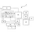
以下、本発明に係る撮像装置の例であるデジタルカメラの例について図面を参照しながら説明する。図1は、本発明に係る撮像装置の例であるデジタルカメラの外観構成の例であって、図1(a)は正面図を、図1(b)は上面図を、図1(c)は背面図を示している。 Hereinafter, an example of a digital camera which is an example of an imaging apparatus according to the present invention will be described with reference to the drawings. FIG. 1 is an example of an external configuration of a digital camera that is an example of an imaging apparatus according to the present invention. FIG. 1A is a front view, FIG. 1B is a top view, and FIG. Shows a rear view.
図1(a)において、デジタルカメラ1の正面(前面)には、撮像に用いられる主撮像光学系(第1の撮像光学系)を構成する撮像レンズ5を含む鏡胴ユニット6と、フラッシュ動作をするストロボ発光部7と、被写体を視認するための光学ファインダ8と、主撮像光学系とは異なる光学系であって被写体までの距離を測距するための外部AF処理に用いる光学系である補助光学系16(第2の撮像光学系)と、を有している。 In FIG. 1A, on the front surface (front surface) of the
また、図1(b)において、デジタルカメラ1の上面には、シャッタースイッチであるレリーズボタン2と、電源ボタン3と、撮影モードや再生モードなどからなる動作モードの切り替えに用いる切替ダイヤル4と、を有している。 In FIG. 1B, on the upper surface of the
また、図1(c)において、デジタルカメラ1の背面には、撮像動作時に被写体像が表示され、また、再生動作時には記録されている被写体画像が表示される表示部を構成する液晶モニタ(LCDモニタ)9と、光学ファインダ8の接眼レンズ部8aと、広角側ズーム(W)スイッチ10と、望遠側ズーム(T)スイッチ11と、デジタルカメラ1の動作パラメータなどを設定するための設定メニューをLCDモニタ9に表示させるメニュー(MENU)ボタン12と、確定ボタン(OKボタン)13と、を有している。また、デジタルカメラ1の側面内部には、撮影した画像を保存するための図示しないメモリカード14を収納するメモリカード収納部15が設けられている。 In FIG. 1C, a liquid crystal monitor (LCD) that constitutes a display unit on the back of the
次に本実施例に係るデジタルカメラ1の内部構成の例について、図2のブロック図を用いて説明する。図2においてデジタルカメラ1は、撮像レンズ5を介して被写体画像を結像させる受光面を有するCMOS104と、CMOS104から出力される電気信号(デジタルRGB画像信号)に対して所定の画像信号処理を行う信号処理部101と、絞りユニットおよびメカシャッタユニットからなるユニット18を駆動するモータドライバ103と、デジタルカメラ1の全体制御を行うCPU102と、を有してなる。 Next, an example of the internal configuration of the
第1の撮像光学系である主撮像光学系17は、第1のレンズである撮像レンズ5と、ユニット18と、第1の撮像素子であるCMOS104と、を有しなる。 The main imaging
また、デジタルカメラ1は、撮像処理によって取得された画像を一時的に格納するメモリ108と、デジタルカメラ1を図示しない通信インターフェースを介して外部機器と接続させるための通信ドライバ107と、撮像された被写体画像のデータを格納する着脱可能なメモリカード14と、信号処理部101から出力される画像信号を表示可能な信号に変換する表示コントローラとLCDモニタ9からなる表示部109と、利用者が操作可能な各種ボタン類(レリーズボタン2や切替ダイヤル4、メニューボタン12、OKボタン13など)からなる操作部106と、を有してなる。 In addition, the
また、デジタルカメラ1は、主撮像光学系17とは異なる光学系であって、第2のレンズである補助レンズと第2の撮像素子である補助撮像素子とを有してなる第2の撮像光学系である補助光学系16と、CPU102によって発光動作の開始と停止が制御されるストロボ発光部7と、ストロボ発光用のメインコンデンサ105と、を有してなる。 The
補助光学系16は主に、撮像処理において、コントラストAF処理の前に被写体までの距離を測定する外部AF処理に用いられる。 The auxiliary
撮影レンズ5とユニット18を駆動するモータドライバ103は、CPU102からの駆動信号によって、制御される。 A
CMOS104は、2次元に配列された受光素子を有しており、この受光素子に結像された光学像が電荷に変換されて、駆動部113から送信される読出し信号タイミングに応じて外部に電気信号として読み出される素子である。CMOS104を構成する複数の画素(受光素子)上にはRGB原色フィルタ(以下、「RGBフィルタ」という。)が配置されており、RGB3原色に対応した電気信号(デジタルRGB画像信号、または、RAW−RGBデータという。)が出力される。 The
信号処理部101は、その構成について詳細は図示をしないが、CMOS104から出力されるRAW−RGBデータを所定の読み出し速度と画像範囲で読み出すCMOSインターフェース(以下、「CMOSI/F」という。)と、メモリ108へのデータの書き出しと読み込みを制御するメモリコントローラと、読み出されたRAW−RGBデータをYUV形式の画像情報に変換するYUV変換部と、画像情報を表示部のサイズや記録形式のサイズに合わせて変更するリサイズ処理部と、画像情報の表示出力を制御する表示出力制御部と、画像情報をJPEG形式などに変換するデータ圧縮部と、画像情報のメモリカードへの書き込み、又はメモリカードからの読み出しに用いられるメディアインターフェース(以下、「メディアI/F」という。)と、操作部106に対する操作に応じて、図示しないROMに記憶された制御プログラムに基づいてデジタルカメラ1全体のシステム制御等を行う制御部と、を有してなる。 Although not shown in detail for the configuration of the
メモリ108には、CMOSI/Fに取り込まれたRAW−RGBデータが保存されると共に、YUV変換部で変換処理されたYUVデータ(YUV形式の画像情報)が保存される。また、メモリ108には、データ圧縮部で圧縮処理されたJPEG形式の画像情報が保存される。なお、YUVデータは、輝度データ(Y)と、色差(輝度データと青色(B)データの差分(U)と、輝度データと赤色(R)の差分(V))の情報で色を表現する形式である。 The
補助光学系16が有する補助撮像素子は、2次元に配列された受光素子である。補助光学系16は、この2次元撮像素子を少なくとも2つ以上備えていて、それぞれの補助撮像素子で取得した被写体画像の視差を算出し、三角測量の原理を応用して被写体までの距離を算出することができる。 The auxiliary imaging element included in the auxiliary
次に、本実施例に係るデジタルカメラ1において実行されるモニタリング動作と、撮像処理の一例である静止画撮影の例について説明する。デジタルカメラ1が静止画撮影モードで動作しているときは、以下に説明するモニタリング動作が実行されながら撮影動作が行われる。 Next, a monitoring operation executed in the
デジタルカメラ1を静止画撮影モードで動作させるときは、利用者が、電源ボタン3を操作して動作電源を投入した後に、切替ダイヤル4を操作して「静止画撮影モード」を選択する操作を行えばよい。 When operating the
静止画撮影モードが選択されたデジタルカメラ1は、CPU102からモータドライバ103に対して制御信号が出力されて、フォーカスレンズを含む撮像レンズ5が撮影可能位置に移動する。また、CPU102は、CMOS104、信号処理部101、および表示部109などを起動させる。 In the
その後、撮像レンズ5を介して被写体の像光がCMOS104の受光面(受光素子)に結像されると、これに応じた画像電気信号がCMOS104から出力される。この被写体像に応じた画像電気信号は、CDS/PGA111を介してA/D変換部112に入力され、12ビットのRAW−RGBデータに変換される。変換されたRAW−RGBデータは、信号処理部101のCMOSI/Fを介して信号処理部101によって所定の読み出し速度で読み出されて、メモリ108であるSDRAMに保存される。 Thereafter, when the image light of the subject is imaged on the light receiving surface (light receiving element) of the
メモリ108に保存されたRAW−RGBデータは所定のタイミングで読み出されて、信号処理部101が有するYUV変換部によって、表示部109のLCDモニタ9において表示可能な形式であるYUVデータ(YUV信号)に変換される。この変換されたYUVデータも、メモリコントローラを介してメモリ108であるSDRAMに保存される。 The RAW-RGB data stored in the
その後、所定のタイミングでメモリコントローラを介してメモリ108からYUVデータが読み出されて、表示部109に出力され、液晶モニタ9に被写体像が表示される。この表示に係る一連の動作を「モニタリング動作」という。 Thereafter, YUV data is read from the
上記のモニタリング動作の間は、CMOS104の全画像領域に相当するRAW−RGBデータが1/30秒間隔で読み出されて、1フレームのYUVデータを構成し、LCDモニタ9に表示される。「モニタリング動作」は、レリーズボタン2に対する押圧(半押も含む)操作が検出されるまで継続し、モニタリング動作が継続している間は、電子ファインダとして機能するLCDモニタ9に被写体の画像が表示されている。 During the above monitoring operation, RAW-RGB data corresponding to the entire image area of the
モニタリング動作によってLCDモニタ9に画像が表示されて、デジタルカメラ1の利用者は、被写体画像を視認することができる。なお、表示部109からTVビデオ信号として出力して、ビデオケーブルを介して外部のTV(テレビ)に撮影画像(動画)を表示することもできる。 An image is displayed on the
信号処理部101は、上記のモニタリング動作を行いつつ、CMOSI/Fを介して読み出されたRAW−RGBデータによって、AF(自動合焦)評価値と、AE(自動露出)評価値(コントラスト値)と、AWB(オートホワイトバランス)評価値と、を含む撮像処理に用いるデータを算出する処理を行う。 The
AF評価値とは、例えば高周波成分抽出フィルタの出力を積分した値や、近接画素の輝度差を積分した値をいう。撮像レンズ5が被写体に合焦しているときは、被写体のエッジ部分がはっきりとしているため高周波成分が一番高くなる。これを利用して、AF動作時(合焦検出動作時)には、撮影レンズ5に含まれるフォーカスレンズを駆動して、各レンズ位置におけるAF評価値を算出し、算出されたAF評価値が最大になるレンズ位置を検出することで、合焦位置を特定することができる。この一連の動作をAF動作という。 The AF evaluation value refers to, for example, a value obtained by integrating the output of the high frequency component extraction filter or a value obtained by integrating the luminance difference between adjacent pixels. When the
AE評価値およびAWB評価値とは、RAW−RGBデータにおけるRGB値のそれぞれの積分値から算出されるものであり、例えば、CMOS104の全画素の受光面に対応した画面を256エリアに等分割(水平16分割、垂直16分割)し、それぞれのエリア毎に算出したRGBの積算値をいう。 The AE evaluation value and the AWB evaluation value are calculated from the integrated values of the RGB values in the RAW-RGB data. For example, the screen corresponding to the light receiving surface of all the pixels of the
信号処理部101は、RGB積算値を用いて被写体像を捉えている画面(CMOS104の受光面から出力される画像信号の全範囲)を等分割したエリア毎に輝度を算出し、この算出された輝度の分布に基づいて適正な露光量を決定して、この決定された露光量に基づいて、露光条件(電子シャッタ回数、絞りユニットの絞り値等)を設定する処理を行う。これら一連の処理をAE処理という。 The
また、信号処理部101は、RGB積算値の分布から被写体の光源の色に合わせた制御値を決定し、この決定された制御値に基づいてYUV変換部において、RAW−RGBデータをYUVデータに変換するときのホワイトバランスを合わせる処理を行う。これら一連の処理をAWB処理という。 Further, the
上記にて説明をしたAE処理とAWB処理は、モニタリング動作の間は連続的に行われている。このようなモニタリング動作の最中に、レリーズボタン2が押圧(半押しから全押し)操作されると、モニタリング動作から静止画撮影動作に移行する。 The AE process and the AWB process described above are continuously performed during the monitoring operation. If the
静止画撮影動作は、レリーズボタン2への押圧(半押しから全押し)操作が検出されたことをトリガーとして開始される。静止画撮影動作が実行されるとまずCPU102が補助光学系16から画像を読み出して、被写体までの距離を算出する。続いて、算出された距離に基づいてモータドライバ103への駆動指令が出力され、この駆動指令により、モータドライバ103が撮影レンズ5に含まれるフォーカスレンズを所定の位置に移動させる。 The still image shooting operation is triggered by the detection of a pressing operation on the release button 2 (half press to full press). When the still image shooting operation is executed, the
その後、所定の範囲内でフォーカスレンズを駆動させてAF評価値を算出し、AF評価値が極大になるレンズ位置にフォーカスレンズを移動させて合焦させ、上記において説明したAE処理が行われる。AE処理によって露光が完了した時点で、CPU102からモータドライバ103への駆動指令によりユニット18に含まれるメカシャッタが閉じられて、CMOS104から静止画用のアナログRGB画像信号が出力される。その後、モニタリング動作時と同様にRAW−RGBデータに変換される。 Thereafter, the focus lens is driven within a predetermined range to calculate the AF evaluation value, the focus lens is moved to the lens position where the AF evaluation value is maximized, and the AE process described above is performed. When the exposure is completed by the AE process, the mechanical shutter included in the
変換されたRAW−RGBデータは、信号処理部101のCMOSI/Fに取り込まれて、YUV変換部によってYUVデータに変換され、メモリコントローラを介してメモリ108に保存される。保存されたYUVデータは所定のタイミングでメモリ108から読み出されて、信号処理部101に含まれるリサイズ処理部において記録画素数に対応するサイズに変換され、データ圧縮部においてJPEG形式等の画像情報へと圧縮変換される。 The converted RAW-RGB data is taken into the CMOS I / F of the
圧縮された画像情報は、再度メモリ108に書き戻された後にメモリコントローラを介してメモリ108から読み出されて、メディアI/Fを介してメモリカード14に記録される。 The compressed image information is written back to the
補助光学系16は、図示しない測距用レンズを介して図示しない測距素子に結像した被写体像に応じた画像データを出力することができる。信号処理部101は、補助光学系16から、画像データを読み出し、この測距用画像データを用いて被写体までの距離を算出する。この算出された距離に応じたレンズ位置に、フォーカスレンズを移動させた後、前述したAF処理をそのレンズ位置を中心に行うことで、フォーカスレンズを全駆動範囲に渡って駆動させることなく、合焦位置を算出できる。 The auxiliary
なお、補助光学系16ではズーム操作を行うことはできない。本実施例では、補助光学系16の測距用レンズを介して測距素子に結像した被写体像に応じた画像データの画角は、主撮像光学系17が有するズームレンズが最も広角側に位置する場合の主撮像光学系17で得られる画像データの画角とほぼ同じであるとする。 The auxiliary
主撮像光学系17においてズーム操作が行われた場合には、補助光学系16による画角と主撮像光学系17による画角が一致しなくなる。この場合には、主撮像光学系17で得られる画像データが、補助光学系16で得られる画像データ上のどの領域に対応するかを、テンプレートマッチング等を行って求める。そして、補助光学系16で得られる画像データにおいて主撮像光学系17で得られる画像データに対応する領域の画像データを用いて、被写体までの距離算出、及び後述する補助画像表示を行う。 When the zoom operation is performed in the main imaging
ここでデジタルカメラ1は、撮像光学系17からモニタリング用の画像データを読み出すことができないときであっても、補助光学系16からは読み出すことができる。つまり、AF処理の高速化を行うために、撮像光学系17から読み出された画像データによるモニタリング動作を停止するとき、補助光学系16から読み出した画像データを用いてモニタリング動作を行うことで、被写体の移動に容易に追随することができるようになる。 Here, the
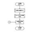
デジタルカメラ1が、補助光学系16から読み出された画像を用いてモニタリング動作を行うときに、LCDモニタ9に表示される画像を「補助画像」という。以下において、本発明に係る撮像装置が備える「補助画像表示機能」について、図3のフローチャートを用いて説明する。図3において各処理ステップをS1、S2・・・、のように表記する。 An image displayed on the
デジタルカメラ1を撮影モードで動作させるとモニタリング表示が行われる(S1)。続いてレリーズボタン2が半押しされたか否かを判定する(S2)。レリーズボタン2が半押し(RL1)されるまで、モニタリング表示はそのまま継続される(S2のN)。 When the
レリーズボタン2が半押しされたとき(S2のY)、AF処理が開始される(S3)。AF処理(S3)の詳細について図4のフローチャートを用いて説明する。図4において、各処理ステップは、S31、S32・・・のように表記する。 When the
AF処理ではまず、補助光学系16を用いた外部AF処理を行う。外部AF処理(S31)は、補助AF光学系16が備える2つの撮像素子によって読み出された画像から視差を算出し、この視差を用いて三角測量の原理を応用して被写体までの距離を算出する処理である。補助光学系16が備える撮像素子は受光素子が2次元に配列されたものである。CPU102は、外部AF処理(S31)において、算出された距離に応じた位置にフォーカスレンズを移動させる。 In the AF processing, first, external AF processing using the auxiliary
続いてコントラストAF処理(S32)が行われる。コントラストAF処理(S32)は、外部AF処理(S31)によって移動させたフォーカスレンズを所定の範囲内で移動させながらコントラスト値が最大となるレンズ位置を特定する処理である。コントラストAF処理(S32)の詳細について、図5のフローチャートを用いて説明する。図5において、各処理ステップをS321、S322、・・・のように表記する。 Subsequently, contrast AF processing (S32) is performed. The contrast AF process (S32) is a process for specifying the lens position where the contrast value is maximized while moving the focus lens moved by the external AF process (S31) within a predetermined range. Details of the contrast AF process (S32) will be described with reference to the flowchart of FIG. In FIG. 5, each processing step is expressed as S321, S322,.
まず、前述したように、フォーカスレンズを駆動させながらコントラスト値を算出して、コントラスト値が最大値となるレンズ位置を特定するコントラストAF処理が開始される。コントラストAF処理には、撮像光学系17から読み出される画像信号の一部の画像信号による部分画像を用いる。このため、主画像一時停止処理(S321)が行われる。主画像とは、撮像光学系17から読み出された画像を用いてモニタリング動作(図3のS1)を行う際に、LCDモニタ9に表示される画像をいう。主画像一時停止処理(S321)は、コントラストAF処理(S32)が開始されたときに表示されている画像を静止させて表示させ続ける処理、または、撮像光学系17から読み出された画像の表示を停止させる処理である。 First, as described above, a contrast AF process for calculating a contrast value while driving the focus lens and specifying a lens position where the contrast value becomes the maximum value is started. In contrast AF processing, a partial image based on a part of the image signal read from the imaging
次に、補助画面表示判定処理(S322)が行われる。補助画面表示判定処理(S322)は、補助画面表示を行うか、または行わないか、を判定する処理である。撮像光学系17からの画像読み出しを、部分読み出しではなく、全画像領域に係る読み出しとしても、所定の時間以下でコントラストAF処理が終了すると見込めるときは、補助画面を表示しても、短時間で主画像に切り替わってしまうため、短時間で表示が切り替わることの見づらさの方が目立つ。また、撮像光学系17に係る部分読み出しを行ったとしても、所定の時間以内でコントラストAF処理が終了できるならば、補助画面表示を行わない方が、短時間で表示が切り替わることの見づらさを回避することができる。 Next, an auxiliary screen display determination process (S322) is performed. The auxiliary screen display determination process (S322) is a process for determining whether or not to display the auxiliary screen. Even if the image reading from the imaging
「第1の例」
補助画面表示判定処理(S322)は、いくつかの判定方法を有する。例えば、撮像光学系17の焦点距離が広角側の場合には被写界深度が深いため、コントラストAF処理を行うスキャンステップ数が望遠側よりも少なくなる。この場合、主画像によるモニタリング動作を停止させても、その停止時間が短いので、補助画面を表示させなくても、被写体が表示範囲外に移動して、逃してしまう可能性は低い。この場合、補助画面に切り換えると、かえって表示が見づらくなる。そのため、撮像光学系17の焦点距離が設定された値よりも短いときは、部分読み出しAFによる主像画面停止中でも補助画面表示を行わず(S322のN)、撮像光学系17の焦点距離が設定された値よりも長いときは、補助画面表示処理(S323)に移行する(S322のY)。"First example"
The auxiliary screen display determination process (S322) has several determination methods. For example, since the depth of field is deep when the focal length of the imaging
「第2の例」
上記した補助画面表示判定処理(S322)は、言い換えると、撮像光学系17の画角の広さによって、主画像によるモニタリング停止時間の長短を判定するものである。すなわち、撮像光学系17の画角が広角側の場合には、被写界深度が深いため、コントラストAF処理を行うスキャンステップ数が、画角が望遠側のときよりも少なくなるから、主画像によるモニタリング停止時間が短くなる。よって、撮像光学系17の画角が、予め設定された閾値となる画角よりも広いときは、部分読み出しAFによる主画像停止中の補助画面表示を行わず(S322のN)、撮像光学系17の画角が、予め設定された閾値となる画角よりも狭いときは、補助画面表示処理(S323)に移行する(S322のY)。"Second example"
In other words, the auxiliary screen display determination process (S322) described above determines the length of the monitoring stop time of the main image according to the angle of view of the imaging
「第3の例」
また、スキャンステップ数が所定の値よりも少なければ、補助画面表示を開始せず(S322のN)、スキャンステップ数が所定の値よりも多ければ、補助画面表示処理(S323)に移行するようにしてもよい(S322のY)。"Third example"
If the number of scan steps is less than the predetermined value, the auxiliary screen display is not started (N in S322), and if the number of scan steps is larger than the predetermined value, the process proceeds to the auxiliary screen display process (S323). (Y in S322).
デジタルカメラ1に撮影モードにおいて複数の露光条件やシャッタ速度を予め記憶しておき選択できるいわゆる「シーン」選択機能が備わっているならば、選択されているシーンや、直前に行われたAF処理結果などの情報から、コントラストAF処理で実施するスキャンステップ数を少なくする方法がある。 If the
そのため、必ずしも広角側ならスキャンステップ数が少なく、望遠側ならスキャンステップ数が多くなるというわけではない。コントラストAF処理を行うスキャンステップ数が少ない場合には、主画面を停止させたままコントラストAF処理を行っても、画面が停止する時間は短いため、補助画面を表示させずとも被写体を逃してしまう可能性が低く、また、補助画面と主画面の切り換えが短時間で行われることによる表示の見づらさのほうが目立ってくる。 For this reason, the number of scan steps is not always large on the wide-angle side, and the number of scan steps is not large on the telephoto side. When the number of scan steps for performing contrast AF processing is small, even if contrast AF processing is performed while the main screen is stopped, the time for which the screen stops is short, so the subject is missed without displaying the auxiliary screen. The possibility is low, and the display is more difficult to see due to switching between the auxiliary screen and the main screen in a short time.
そのため実施予定のスキャンステップ数が設定されたスキャンステップ数より少ない場合には部分読み出しAFによる主像画面停止中でも補助画面を行わず(S322のN)、実施予定のスキャンステップ数が設定されたスキャンステップ数より多い場合には補助画面表示処理を行えばよい(S322のY,S323)。 Therefore, if the number of scan steps scheduled to be performed is less than the set number of scan steps, the auxiliary screen is not performed even when the main image screen is stopped by partial readout AF (N in S322), and the scan with the number of scan steps scheduled to be performed is set. If the number is larger than the number of steps, an auxiliary screen display process may be performed (Y in S322, S323).
「第4の例」
また、推定コントラストAF時間が所定の時間よりも短ければ、補助画面表示を開始せず(S322のN)、推定コントラストAF時間が所定の時間よりも長ければ、補助画面表示処理(S323)に移行するようにしてもよい(S322のY)。"Fourth example"
If the estimated contrast AF time is shorter than the predetermined time, the auxiliary screen display is not started (N in S322), and if the estimated contrast AF time is longer than the predetermined time, the process proceeds to the auxiliary screen display process (S323). You may make it do (Y of S322).
コントラストAF処理の速度を上げるには、コントラスト値を算出するための画像取得フレームレートを速くすればよい。これにより、フォーカスレンズのスキャンステップ数が多くても高速なフレームレートで画像読み出しを行うことができるので、コントラストAFに係る処理時間が短くなる。一方、スキャンステップ数が少なくても、フレームレートが低速ならば、コントラストAF処理に要する時間は長くなる。一般に、高輝度の被写体に対しては高速フレームレートで撮像素子を駆動させることができるが、低輝度の被写体に対しては露光時間を長くする必要があるため、低速フレームレートで撮像素子を駆動させることになる。 In order to increase the speed of the contrast AF process, the image acquisition frame rate for calculating the contrast value may be increased. As a result, even when the number of scan steps of the focus lens is large, image reading can be performed at a high frame rate, so that the processing time for contrast AF is shortened. On the other hand, even if the number of scan steps is small, if the frame rate is low, the time required for the contrast AF process becomes long. In general, the image sensor can be driven at a high frame rate for high-luminance subjects, but the exposure time must be increased for low-luminance subjects, so the image sensor is driven at a low frame rate. I will let you.
そのため、撮像光学系17に設定されているスキャンステップ数とフレームレートから、コントラストAF時間を推定し、推定された時間が所定の時間よりも短い場合には部分読み出しAFによる主像画面停止中でも補助画面表示を行わず(S322のN)、推定された時間が所定の時間よりも長い場合には補助画面表示処理を行えばよい(S322のY,S323)。 Therefore, the contrast AF time is estimated from the number of scan steps set in the imaging
補助画面表示判定処理(S322)において、上記のような条件に基づき、補助画面の表示をしないと判定されたとき(S322のN)、コントラストAF終了判定処理(S324)に移行する。補助画面の表示をすると判定されたとき(S322のY)、補助画面表示処理(S323)に移行する。 In the auxiliary screen display determination process (S322), when it is determined not to display the auxiliary screen based on the above conditions (N in S322), the process proceeds to the contrast AF end determination process (S324). When it is determined to display the auxiliary screen (Y in S322), the process proceeds to an auxiliary screen display process (S323).
補助画面表示処理(S323)の詳細な例について、図6のフローチャートを用いて説明する。図6において各処理ステップをS3231、S3232・・・のように表記する。まず、補助光学系16から画像を読み出す処理を行う(S3231)。前述したように、補助光学系16は、2次元の撮像素子を有している。補助光学系16が有する2つの撮像素子のうち、いずれか一方の撮像素子から画像を読み出せばよい。 A detailed example of the auxiliary screen display process (S323) will be described with reference to the flowchart of FIG. In FIG. 6, each processing step is expressed as S3231, S3232,. First, a process of reading an image from the auxiliary
続いて、読み出された画像を主モニタリング画像に重ねて表示するのに適した表示サイズとなるように、リサイズ処理を行う(S3232)。リサイズ処理(S3232)は、信号処理部101によって行われる。続いて、リサイズ処理が施された画像(補助モニタリング画像)を、主モニタリング画像に重ね合わせる合成処理を行う(S3233)。 Subsequently, a resizing process is performed so that the read image has a display size suitable for displaying on the main monitoring image (S3232). The resizing process (S3232) is performed by the
続いて、合成されたモニタリング画像をLCDモニタ9に出力する(S3234)。このように、静止画像となっている主モニタリング画像に、補助モニタリング画像を重ねて表示することで、コントラストAF処理の間に、被写体が表示範囲に外れることなく、追随することができるようになる。 Subsequently, the synthesized monitoring image is output to the LCD monitor 9 (S3234). In this way, by displaying the auxiliary monitoring image superimposed on the main monitoring image that is a still image, the subject can follow the contrast AF process without being out of the display range. .
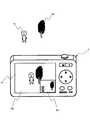
ここで、補助画面表示処理(S322)においてLCDモニタ9に表示される画像の例について説明する。図7は本実施例に係るデジタルカメラ1が有するLCDモニタ9に表示される補助画面の例を示す模式図である。図7において、被写体を人物X1と木X2とする。デジタルカメラ1が有するLCDモニタ9には、撮像光学系17を介して読み出された主モニタリング画像100と、補助光学系16を介して読み出された補助モニタリング画像101が、表示されている。 Here, an example of an image displayed on the
デジタルカメラ1がコントラストAF処理を行っているとき、主モニタリング画像100は、事前に表示されていた画像を表示した状態、表示画像が静止している。しかし、被写体の状態はその間であっても変化する。すなわち、人物X1が移動して木X2から離れているときは、主モニタリング画像100は変わらないが、補助モニタリング画像101は所定のフレームレートで更新されるので、被写体の現時点の状態を逐次表示することができる。 When the
このように本発明に係る撮像装置によれば、コントラストAF処理の間であっても、被写体のモニタリング画像を表示し続けることができる。 As described above, according to the imaging apparatus of the present invention, it is possible to continue displaying the monitoring image of the subject even during the contrast AF process.
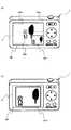
ここで、本実施例に係るデジタルカメラ1の補助画面表示処理(S323)において、LCDモニタ9に表示される画像の別の例について、図8を用いて説明する。 Here, another example of an image displayed on the
図8(a)に示すように、LCDモニタ9に表示される補助モニタリング画像101は、主モニタリング画像100の右上(101a)、左上(101b)、左下(101c)の中から、選択した位置に表示されてもよい。当該選択操作は、図示しない設定画面において、補助画面表示位置設定を行えばよい。この補助画面表示位置設定によって、画像合成処理(S3233)が行われて、合成画像が生成される。 As shown in FIG. 8A, the
また、図8(b)に示すように、主モニタリング画像100とほぼ同じ大きさで、補助モニタリング画像101dを表示してもよい。この場合、主モニタリング画像100の代わりに補助モニタリング画像101dを表示してもよい。 In addition, as shown in FIG. 8B, the
図5に戻る。補助画面表示処理(S323)に続いて、コントラストAF処理の終了判定処理が行われる(S324)。すなわち、コントラスト値の最大値が特定されて、所定の位置にフォーカスレンズが移動されているか否かを判定する。コントラストAF処理が終了していなければ(S324のN)、補助画面表示判定処理(S322)において再度補助画面表示を行うか、または、行わないか、の判定をする。 Returning to FIG. Subsequent to the auxiliary screen display process (S323), an end determination process for the contrast AF process is performed (S324). That is, the maximum contrast value is specified, and it is determined whether or not the focus lens is moved to a predetermined position. If the contrast AF process has not ended (N in S324), it is determined whether or not the auxiliary screen display is performed again in the auxiliary screen display determination process (S322).
コントラストAF処理が終了していれば(S324のY)、図4に戻り、LCDモニタ9に表示されている被写体画像に対して合焦表示処理が行われる(S33)。合焦表示とは、AF処理が終了して被写体の撮影が行える状態になったことを利用者に知らせる表示をいう。 If the contrast AF process has been completed (Y in S324), the process returns to FIG. 4 and the focus display process is performed on the subject image displayed on the LCD monitor 9 (S33). The in-focus display is a display that informs the user that the AF process has been completed and the subject can be photographed.
図3に戻る。AF処理(S3)が終了した後、レリーズボタン2が全押しされたか否かを判定する(S4)。レリーズボタンが全押しされた状態(RL2という。)が検出されたとき(S4のY)、撮影処理が行われる(S5)。撮影処理が終了した後に、モニタリング再開処理が行われる(S6)。 Returning to FIG. After the AF process (S3) ends, it is determined whether or not the
モニタリング再開処理(S6)は、補助光学系16からの画像読み出しを停止し、撮像光学系17からの画像読み出しを再開して、LCDモニタ9のモニタリング動作を再開させる処理である。 The monitoring restart process (S6) is a process of stopping the image reading from the auxiliary
RL2が検出されず(S4のN)、RL1が検出されているときは(S7のY)、合焦表示処理(図5のS33)を継続する。RL1が検出されないときは(S7のN)、モニタリング再開処理が行われる(S6)。 If RL2 is not detected (N in S4) and RL1 is detected (Y in S7), the focus display process (S33 in FIG. 5) is continued. When RL1 is not detected (N in S7), a monitoring restart process is performed (S6).
以上説明をした本実施例に係る撮像装置によれば、コントラストAF処理を高速化させるために部分読み出し処理を行ったときであっても、モニタリング動作を停止させることなく、被写体画像をLCDモニタ9に表示させ続けることができる。 According to the imaging apparatus according to the present embodiment described above, the subject image is displayed on the
このように、本発明に係る撮像装置によれば、コントラストAF処理の間に被写体が移動したとしても、その移動を容易に追従することができる。 Thus, according to the imaging apparatus according to the present invention, even if the subject moves during the contrast AF process, the movement can be easily followed.
1 撮像装置
9 表示部
16 補助光学系
17 撮像光学系
101 信号処理部DESCRIPTION OF
Claims (6)
Translated fromJapanese第2のレンズと第2の撮像素子とを有してなる第2の撮像光学系と、
上記第1の撮像素子及び上記第2の撮像素子の少なくとも一方から画像信号を読み出して、表示画像を生成する信号処理部と、
上記生成された表示画像が表示される表示部と、
を有し、コントラストAF処理を用いて合焦位置を特定する撮像装置であって、
上記信号処理部は、
上記コントラストAF処理が行われるときに、
上記第1の撮像素子から画像信号の一部を読み出し、読み出した一部の画像信号を用いてコントラスト値の算出を行い、
上記第2の撮像素子から読み出される画像信号によって上記表示画像を生成することを特徴とする撮像装置。A first imaging optical system having a first lens and a first imaging device;
A second imaging optical system having a second lens and a second imaging element;
A signal processing unit that reads out an image signal from at least one of the first image sensor and the second image sensor and generates a display image;
A display unit on which the generated display image is displayed;
An imaging apparatus for specifying a focus position using contrast AF processing,
The signal processor is
When the contrast AF process is performed,
A part of the image signal is read from the first image sensor, the contrast value is calculated using the read part of the image signal,
An imaging apparatus, wherein the display image is generated by an image signal read from the second imaging element.
上記コントラストAF処理が行われるときに、
上記第1の撮像素子から読み出された画像信号による上記表示画像の生成を停止することを特徴とする請求項1記載の撮像装置。The signal processor is
When the contrast AF process is performed,
The imaging apparatus according to claim 1, wherein generation of the display image by an image signal read from the first imaging element is stopped.
上記コントラストAF処理が行われるときに、
上記第1の撮像素子から読み出された画像信号と、上記第2の撮像素子から読み出された画像信号と、を合成して上記表示画像を生成することを特徴とする請求項1または2記載の撮像装置。The signal processor is
When the contrast AF process is performed,
3. The display image is generated by synthesizing an image signal read from the first image sensor and an image signal read from the second image sensor. The imaging device described.
上記コントラストAF処理が行われるときに、
上記第1の撮像光学系の焦点距離が、所定の焦点距離よりも長いか否かの判定をし、
上記第1の撮像光学系の焦点距離が上記所定の焦点距離よりも長いとき、上記第2の撮像素子から読み出された画像信号によって上記表示画像を生成することを特徴とする請求項1乃至3のいずれかに記載の撮像装置。The signal processor is
When the contrast AF process is performed,
Determining whether the focal length of the first imaging optical system is longer than a predetermined focal length;
The display image is generated by an image signal read from the second image sensor when the focal length of the first imaging optical system is longer than the predetermined focal length. 4. The imaging device according to any one of 3.
上記コントラストAF処理が行われるときに、
上記第1の撮像光学系が有するフォーカスレンズのスキャンステップ数が所定のスキャンステップ数よりも多いか否かの判定をし、
上記フォーカスレンズのスキャンステップ数が上記所定のスキャンステップ数よりも多いとき、上記第2の撮像素子から読み出された画像信号によって上記表示画像を生成することを特徴とする請求項1乃至3のいずれかに記載の撮像装置。The signal processor is
When the contrast AF process is performed,
Determining whether the number of scan steps of the focus lens included in the first imaging optical system is greater than a predetermined number of scan steps;
4. The display image according to claim 1, wherein when the number of scan steps of the focus lens is larger than the predetermined number of scan steps, the display image is generated by an image signal read from the second image sensor. The imaging device according to any one of the above.
上記コントラストAF処理が行われるときに、
当該コントラストAFに係る処理時間が、所定の時間よりも長いか否かの判定をし、
上記処理時間が上記所定の時間よりも長いときは、上記第2の撮像素子から読み出された画像信号によって上記表示画像を生成することを特徴とする請求項1乃至3のいずれかに記載の撮像装置。The signal processor is
When the contrast AF process is performed,
It is determined whether or not the processing time related to the contrast AF is longer than a predetermined time,
4. The display image according to claim 1, wherein when the processing time is longer than the predetermined time, the display image is generated by an image signal read from the second image sensor. Imaging device.
Priority Applications (6)
| Application Number | Priority Date | Filing Date | Title |
|---|---|---|---|
| JP2012066553AJP2013008004A (en) | 2011-05-25 | 2012-03-23 | Imaging apparatus |
| EP12789634.8AEP2715428B1 (en) | 2011-05-25 | 2012-05-23 | Imaging device |
| US14/122,070US9113082B2 (en) | 2011-05-25 | 2012-05-23 | Imaging device |
| CN201280033921.7ACN103649807B (en) | 2011-05-25 | 2012-05-23 | Imaging device |
| KR1020137033705AKR20140014288A (en) | 2011-05-25 | 2012-05-23 | Imaging device |
| PCT/JP2012/063831WO2012161344A1 (en) | 2011-05-25 | 2012-05-23 | Imaging device |
Applications Claiming Priority (3)
| Application Number | Priority Date | Filing Date | Title |
|---|---|---|---|
| JP2011117370 | 2011-05-25 | ||
| JP2011117370 | 2011-05-25 | ||
| JP2012066553AJP2013008004A (en) | 2011-05-25 | 2012-03-23 | Imaging apparatus |
Publications (1)
| Publication Number | Publication Date |
|---|---|
| JP2013008004Atrue JP2013008004A (en) | 2013-01-10 |
Family
ID=47217404
Family Applications (1)
| Application Number | Title | Priority Date | Filing Date |
|---|---|---|---|
| JP2012066553APendingJP2013008004A (en) | 2011-05-25 | 2012-03-23 | Imaging apparatus |
Country Status (6)
| Country | Link |
|---|---|
| US (1) | US9113082B2 (en) |
| EP (1) | EP2715428B1 (en) |
| JP (1) | JP2013008004A (en) |
| KR (1) | KR20140014288A (en) |
| CN (1) | CN103649807B (en) |
| WO (1) | WO2012161344A1 (en) |
Cited By (1)
| Publication number | Priority date | Publication date | Assignee | Title |
|---|---|---|---|---|
| US10382665B2 (en) | 2016-12-30 | 2019-08-13 | Samsung Electronics Co., Ltd. | Auto focus method and electronic device for performing the same |
Families Citing this family (7)
| Publication number | Priority date | Publication date | Assignee | Title |
|---|---|---|---|---|
| JP6311868B2 (en)* | 2013-11-07 | 2018-04-18 | 株式会社Joled | Image processing circuit, image processing method, and display device |
| JP6256132B2 (en) | 2014-03-14 | 2018-01-10 | 株式会社リコー | Imaging system |
| CN104363376A (en)* | 2014-11-28 | 2015-02-18 | 广东欧珀移动通信有限公司 | Continuous focusing method, device and terminal |
| CN104333702A (en)* | 2014-11-28 | 2015-02-04 | 广东欧珀移动通信有限公司 | A method, device and terminal for automatic focusing |
| JP2016158186A (en)* | 2015-02-26 | 2016-09-01 | カシオ計算機株式会社 | Imaging apparatus, imaging method, and imaging program |
| KR102446442B1 (en)* | 2015-11-24 | 2022-09-23 | 삼성전자주식회사 | Digital photographing apparatus and method of operation thereof |
| CN107015288B (en)* | 2017-05-25 | 2018-11-27 | 青岛理工大学 | Multichannel underwater optical imaging method |
Citations (7)
| Publication number | Priority date | Publication date | Assignee | Title |
|---|---|---|---|---|
| JP2003333409A (en)* | 2002-05-10 | 2003-11-21 | Sanyo Electric Co Ltd | Video camera |
| JP2006253829A (en)* | 2005-03-08 | 2006-09-21 | Casio Comput Co Ltd | Camera device and automatic focus control method of camera device |
| JP2006276699A (en)* | 2005-03-30 | 2006-10-12 | Kyocera Corp | Imaging device |
| JP2006293082A (en)* | 2005-04-12 | 2006-10-26 | Mitsubishi Electric Corp | Imaging device |
| JP2009244431A (en)* | 2008-03-28 | 2009-10-22 | Canon Inc | Image pickup apparatus |
| JP2010204385A (en)* | 2009-03-03 | 2010-09-16 | Fujifilm Corp | Stereoscopic imaging apparatus and method |
| JP2011085871A (en)* | 2009-10-19 | 2011-04-28 | Canon Inc | Imaging apparatus |
Family Cites Families (7)
| Publication number | Priority date | Publication date | Assignee | Title |
|---|---|---|---|---|
| JP4050385B2 (en) | 1998-05-21 | 2008-02-20 | オリンパス株式会社 | Electronic imaging device |
| JP2000175100A (en) | 1998-12-04 | 2000-06-23 | Olympus Optical Co Ltd | Electronic camera |
| JP4692770B2 (en)* | 2006-12-27 | 2011-06-01 | 富士フイルム株式会社 | Compound eye digital camera |
| US7859588B2 (en) | 2007-03-09 | 2010-12-28 | Eastman Kodak Company | Method and apparatus for operating a dual lens camera to augment an image |
| JP2011075675A (en)* | 2009-09-29 | 2011-04-14 | Fujifilm Corp | Compound-eye imaging apparatus |
| JP5712519B2 (en) | 2010-07-23 | 2015-05-07 | 株式会社リコー | Imaging apparatus and imaging method |
| JP5609467B2 (en) | 2010-09-15 | 2014-10-22 | 株式会社リコー | Imaging apparatus and imaging method |
- 2012
- 2012-03-23JPJP2012066553Apatent/JP2013008004A/enactivePending
- 2012-05-23CNCN201280033921.7Apatent/CN103649807B/ennot_activeExpired - Fee Related
- 2012-05-23KRKR1020137033705Apatent/KR20140014288A/ennot_activeCeased
- 2012-05-23USUS14/122,070patent/US9113082B2/ennot_activeExpired - Fee Related
- 2012-05-23EPEP12789634.8Apatent/EP2715428B1/ennot_activeNot-in-force
- 2012-05-23WOPCT/JP2012/063831patent/WO2012161344A1/enactiveApplication Filing
Patent Citations (7)
| Publication number | Priority date | Publication date | Assignee | Title |
|---|---|---|---|---|
| JP2003333409A (en)* | 2002-05-10 | 2003-11-21 | Sanyo Electric Co Ltd | Video camera |
| JP2006253829A (en)* | 2005-03-08 | 2006-09-21 | Casio Comput Co Ltd | Camera device and automatic focus control method of camera device |
| JP2006276699A (en)* | 2005-03-30 | 2006-10-12 | Kyocera Corp | Imaging device |
| JP2006293082A (en)* | 2005-04-12 | 2006-10-26 | Mitsubishi Electric Corp | Imaging device |
| JP2009244431A (en)* | 2008-03-28 | 2009-10-22 | Canon Inc | Image pickup apparatus |
| JP2010204385A (en)* | 2009-03-03 | 2010-09-16 | Fujifilm Corp | Stereoscopic imaging apparatus and method |
| JP2011085871A (en)* | 2009-10-19 | 2011-04-28 | Canon Inc | Imaging apparatus |
Cited By (1)
| Publication number | Priority date | Publication date | Assignee | Title |
|---|---|---|---|---|
| US10382665B2 (en) | 2016-12-30 | 2019-08-13 | Samsung Electronics Co., Ltd. | Auto focus method and electronic device for performing the same |
Also Published As
| Publication number | Publication date |
|---|---|
| CN103649807B (en) | 2016-09-14 |
| KR20140014288A (en) | 2014-02-05 |
| EP2715428A1 (en) | 2014-04-09 |
| EP2715428B1 (en) | 2016-06-01 |
| US20140092275A1 (en) | 2014-04-03 |
| US9113082B2 (en) | 2015-08-18 |
| CN103649807A (en) | 2014-03-19 |
| WO2012161344A1 (en) | 2012-11-29 |
| EP2715428A4 (en) | 2014-09-17 |
Similar Documents
| Publication | Publication Date | Title |
|---|---|---|
| JP5779959B2 (en) | Imaging device | |
| JP5054583B2 (en) | Imaging device | |
| JP4980982B2 (en) | Imaging apparatus, imaging method, focus control method, and program | |
| US20120300051A1 (en) | Imaging apparatus, and display method using the same | |
| US20110018970A1 (en) | Compound-eye imaging apparatus | |
| JP5380784B2 (en) | Autofocus device, imaging device, and autofocus method | |
| JP4657960B2 (en) | Imaging method and apparatus | |
| TWI459126B (en) | Image processing device, image processing method and recording medium capable of generating wide-angle image | |
| JP2013008004A (en) | Imaging apparatus | |
| KR20100039430A (en) | Image processor, image processing method, digital camera, and imaging apparatus | |
| CN103842903B (en) | Imaging device, imaging method, and program | |
| JP5051812B2 (en) | Imaging apparatus, focusing method thereof, and recording medium | |
| TW201301866A (en) | Image processing device, image processing method, and recording medium capable of generating wide-angle image | |
| JP2012156644A (en) | Electronic camera, program, and recording media | |
| JP5146015B2 (en) | Imaging apparatus and imaging method | |
| JP2007225897A (en) | In-focus position determining apparatus and method | |
| JP2008263478A (en) | Imaging device | |
| JP5366693B2 (en) | IMAGING DEVICE, IMAGING DEVICE CONTROL METHOD, AND COMPUTER PROGRAM | |
| JP2007101907A (en) | Autofocus control device, image forming apparatus using the autofocus control device, and autofocus control method | |
| JP6225463B2 (en) | Imaging apparatus, imaging method, and recording medium | |
| JP5123010B2 (en) | Imaging apparatus, imaging method, and program for causing computer included in imaging apparatus to execute imaging method | |
| JP6346398B2 (en) | Imaging apparatus and imaging method | |
| JP2001255452A (en) | Autofocus device, digital camera, and portable information input device | |
| JP2007226141A (en) | Imaging apparatus and method | |
| JP5333949B2 (en) | Imaging device |
Legal Events
| Date | Code | Title | Description |
|---|---|---|---|
| A621 | Written request for application examination | Free format text:JAPANESE INTERMEDIATE CODE: A621 Effective date:20150218 | |
| A131 | Notification of reasons for refusal | Free format text:JAPANESE INTERMEDIATE CODE: A131 Effective date:20160209 | |
| A521 | Request for written amendment filed | Free format text:JAPANESE INTERMEDIATE CODE: A523 Effective date:20160411 | |
| A02 | Decision of refusal | Free format text:JAPANESE INTERMEDIATE CODE: A02 Effective date:20160907 |