JP2013007944A - Signal processing apparatus, signal processing method, and program - Google Patents
Signal processing apparatus, signal processing method, and programDownload PDFInfo
- Publication number
- JP2013007944A JP2013007944AJP2011141566AJP2011141566AJP2013007944AJP 2013007944 AJP2013007944 AJP 2013007944AJP 2011141566 AJP2011141566 AJP 2011141566AJP 2011141566 AJP2011141566 AJP 2011141566AJP 2013007944 AJP2013007944 AJP 2013007944A
- Authority
- JP
- Japan
- Prior art keywords
- sound
- audio signal
- pass filter
- signal
- sound quality
- Prior art date
- Legal status (The legal status is an assumption and is not a legal conclusion. Google has not performed a legal analysis and makes no representation as to the accuracy of the status listed.)
- Pending
Links
- 238000012545processingMethods0.000titleclaimsdescription66
- 238000003672processing methodMethods0.000titleclaimsdescription7
- 230000006872improvementEffects0.000claimsabstractdescription117
- 230000005236sound signalEffects0.000claimsabstractdescription85
- 238000001914filtrationMethods0.000claimsabstractdescription44
- 238000000034methodMethods0.000claimsdescription39
- 230000008569processEffects0.000claimsdescription30
- 230000001934delayEffects0.000claimsdescription3
- 238000005516engineering processMethods0.000abstractdescription13
- 238000010586diagramMethods0.000description26
- 230000000875corresponding effectEffects0.000description9
- 230000001052transient effectEffects0.000description6
- 230000000873masking effectEffects0.000description5
- 230000005540biological transmissionEffects0.000description3
- 238000004891communicationMethods0.000description3
- 230000006870functionEffects0.000description2
- 230000003287optical effectEffects0.000description2
- 238000012805post-processingMethods0.000description2
- 230000002411adverseEffects0.000description1
- 230000008859changeEffects0.000description1
- 230000002596correlated effectEffects0.000description1
- 230000003111delayed effectEffects0.000description1
- 230000000694effectsEffects0.000description1
- 238000005562fadingMethods0.000description1
- 239000004973liquid crystal related substanceSubstances0.000description1
- 230000004807localizationEffects0.000description1
- 238000012986modificationMethods0.000description1
- 230000004048modificationEffects0.000description1
- 239000004065semiconductorSubstances0.000description1
- 230000007704transitionEffects0.000description1
- 230000001755vocal effectEffects0.000description1
Images


Classifications
- G—PHYSICS
- G10—MUSICAL INSTRUMENTS; ACOUSTICS
- G10L—SPEECH ANALYSIS TECHNIQUES OR SPEECH SYNTHESIS; SPEECH RECOGNITION; SPEECH OR VOICE PROCESSING TECHNIQUES; SPEECH OR AUDIO CODING OR DECODING
- G10L21/00—Speech or voice signal processing techniques to produce another audible or non-audible signal, e.g. visual or tactile, in order to modify its quality or its intelligibility
- G10L21/04—Time compression or expansion
- G—PHYSICS
- G10—MUSICAL INSTRUMENTS; ACOUSTICS
- G10L—SPEECH ANALYSIS TECHNIQUES OR SPEECH SYNTHESIS; SPEECH RECOGNITION; SPEECH OR VOICE PROCESSING TECHNIQUES; SPEECH OR AUDIO CODING OR DECODING
- G10L19/00—Speech or audio signals analysis-synthesis techniques for redundancy reduction, e.g. in vocoders; Coding or decoding of speech or audio signals, using source filter models or psychoacoustic analysis
- G10L19/04—Speech or audio signals analysis-synthesis techniques for redundancy reduction, e.g. in vocoders; Coding or decoding of speech or audio signals, using source filter models or psychoacoustic analysis using predictive techniques
- G10L19/26—Pre-filtering or post-filtering
- G—PHYSICS
- G10—MUSICAL INSTRUMENTS; ACOUSTICS
- G10L—SPEECH ANALYSIS TECHNIQUES OR SPEECH SYNTHESIS; SPEECH RECOGNITION; SPEECH OR VOICE PROCESSING TECHNIQUES; SPEECH OR AUDIO CODING OR DECODING
- G10L19/00—Speech or audio signals analysis-synthesis techniques for redundancy reduction, e.g. in vocoders; Coding or decoding of speech or audio signals, using source filter models or psychoacoustic analysis
- G—PHYSICS
- G10—MUSICAL INSTRUMENTS; ACOUSTICS
- G10L—SPEECH ANALYSIS TECHNIQUES OR SPEECH SYNTHESIS; SPEECH RECOGNITION; SPEECH OR VOICE PROCESSING TECHNIQUES; SPEECH OR AUDIO CODING OR DECODING
- G10L21/00—Speech or voice signal processing techniques to produce another audible or non-audible signal, e.g. visual or tactile, in order to modify its quality or its intelligibility
- G10L21/02—Speech enhancement, e.g. noise reduction or echo cancellation
- G10L21/038—Speech enhancement, e.g. noise reduction or echo cancellation using band spreading techniques
- G10L21/0388—Details of processing therefor
- G—PHYSICS
- G10—MUSICAL INSTRUMENTS; ACOUSTICS
- G10L—SPEECH ANALYSIS TECHNIQUES OR SPEECH SYNTHESIS; SPEECH RECOGNITION; SPEECH OR VOICE PROCESSING TECHNIQUES; SPEECH OR AUDIO CODING OR DECODING
- G10L19/00—Speech or audio signals analysis-synthesis techniques for redundancy reduction, e.g. in vocoders; Coding or decoding of speech or audio signals, using source filter models or psychoacoustic analysis
- G10L19/008—Multichannel audio signal coding or decoding using interchannel correlation to reduce redundancy, e.g. joint-stereo, intensity-coding or matrixing
Landscapes
- Engineering & Computer Science (AREA)
- Computational Linguistics (AREA)
- Signal Processing (AREA)
- Health & Medical Sciences (AREA)
- Audiology, Speech & Language Pathology (AREA)
- Human Computer Interaction (AREA)
- Physics & Mathematics (AREA)
- Acoustics & Sound (AREA)
- Multimedia (AREA)
- Quality & Reliability (AREA)
- Stereophonic System (AREA)
- Tone Control, Compression And Expansion, Limiting Amplitude (AREA)
Abstract
Description
Translated fromJapanese本技術は、信号処理装置、信号処理方法、及び、プログラムに関し、特に、例えば、一部の周波数成分が間引かれたオーディオ信号を音質を、適切に改善することができるようにする信号処理装置、信号処理方法、及び、プログラムに関する。 The present technology relates to a signal processing device, a signal processing method, and a program, and in particular, for example, a signal processing device that can appropriately improve the sound quality of an audio signal in which some frequency components are thinned out. , A signal processing method, and a program.
オーディオ信号を伝送する場合や、記録媒体に記録する場合には、オーディオ信号のデータ量を低減するために、オーディオ信号の符号化が行われる。 When an audio signal is transmitted or recorded on a recording medium, the audio signal is encoded in order to reduce the data amount of the audio signal.
オーディオ信号の符号化では、例えば、高周波数の周波数成分の、一部の周波数成分を削除することで、オーディオ信号のデータ量を低下させる。 In the encoding of an audio signal, for example, a part of the frequency component of the high frequency is deleted, thereby reducing the data amount of the audio signal.
したがって、オーディオ信号を符号化した符号化データを復号することにより得られる信号には、符号化前のオーディオ信号である原音の高周波数の周波数成分が欠けているため、臨場感が損なわれ、こもったような音になって、音質が低下する。 Therefore, the signal obtained by decoding the encoded data obtained by encoding the audio signal lacks the high-frequency frequency component of the original sound that is the audio signal before encoding, which impairs the sense of presence and makes it muffled. The sound quality deteriorates.
そこで、符号化データを復号することにより得られる信号の低周波数の周波数成分に基づいて、周波数帯域を拡大する(高周波数の周波数成分を生成する)ことにより、高音質の信号を再生する方法が提案されている(例えば、特許文献1を参照)。 Therefore, there is a method for reproducing a high-quality sound signal by expanding a frequency band (generating a high-frequency frequency component) based on a low-frequency component of a signal obtained by decoding encoded data. It has been proposed (see, for example, Patent Document 1).
ところで、例えば、マスキング効果を利用して、原音の一部(所々)の周波数成分が間引かれたオーディオ信号については、音質を、適切に改善することができる技術の提案が要請されている。 By the way, for example, a proposal of a technique that can appropriately improve the sound quality of an audio signal in which a part (location) of the original sound is thinned using the masking effect is required.
本技術は、このような状況に鑑みてなされたものであり、一部(所々)の周波数成分が間引かれたオーディオ信号を音質を、適切に改善することができるようにするものである。 The present technology has been made in view of such a situation, and makes it possible to appropriately improve the sound quality of an audio signal in which some (some) frequency components are thinned out.
本技術の一側面の信号処理装置、及び、プログラムは、一部の周波数成分が間引かれたオーディオ信号を、オールパスフィルタでフィルタリングし、そのフィルタリング結果を、前記オーディオ信号の音質を改善するための改善成分として出力するフィルタ部と、前記オーディオ信号に、前記改善成分を加算することにより、前記オーディオ信号の音質を改善した改善音を生成する加算部とを備える信号処理装置、又は、信号処理装置として、コンピュータを機能させるためのプログラムである。 A signal processing apparatus and a program according to an aspect of the present technology are provided for filtering an audio signal in which some frequency components are thinned out with an all-pass filter, and improving the sound quality of the audio signal based on the filtering result. A signal processing apparatus or a signal processing apparatus comprising: a filter unit that outputs as an improvement component; and an addition unit that generates an improved sound that improves the sound quality of the audio signal by adding the improvement component to the audio signal As a program for causing a computer to function.
本技術の一側面の信号処理方法は、一部の周波数成分が間引かれたオーディオ信号を、オールパスフィルタでフィルタリングし、そのフィルタリング結果を、前記オーディオ信号の音質を改善するための改善成分として出力し、前記オーディオ信号に、前記改善成分を加算することにより、前記オーディオ信号の音質を改善した改善音を生成するステップを含む信号処理方法である。 The signal processing method according to one aspect of the present technology filters an audio signal in which some frequency components are thinned out with an all-pass filter, and outputs the filtering result as an improved component for improving the sound quality of the audio signal. Then, the signal processing method includes a step of generating an improved sound in which the sound quality of the audio signal is improved by adding the improved component to the audio signal.
本技術の一側面においては、一部の周波数成分が間引かれたオーディオ信号が、オールパスフィルタでフィルタリングされ、そのフィルタリング結果が、前記オーディオ信号の音質を改善するための改善成分として出力される。そして、前記オーディオ信号に、前記改善成分を加算することにより、前記オーディオ信号の音質を改善した改善音が生成される。 In one aspect of the present technology, an audio signal from which some frequency components are thinned is filtered by an all-pass filter, and the filtering result is output as an improvement component for improving the sound quality of the audio signal. Then, by adding the improvement component to the audio signal, an improved sound with improved sound quality of the audio signal is generated.
なお、信号処理装置は、独立した装置であっても良いし、1つの装置を構成している内部ブロックであっても良い。 Note that the signal processing device may be an independent device or may be an internal block constituting one device.
また、プログラムは、伝送媒体を介して伝送することにより、又は、記録媒体に記録して、提供することができる。 The program can be provided by being transmitted via a transmission medium or by being recorded on a recording medium.
本技術の一側面によれば、一部の周波数成分が間引かれたオーディオ信号を音質を、適切に改善することができる。 According to one aspect of the present technology, it is possible to appropriately improve the sound quality of an audio signal from which some frequency components are thinned.
[本技術を適用したプレーヤの一実施の形態] [One embodiment of a player to which the present technology is applied]
図1は、本技術を適用したプレーヤの一実施の形態の構成例を示すブロック図である。 FIG. 1 is a block diagram illustrating a configuration example of an embodiment of a player to which the present technology is applied.
図1において、プレーヤは、取得部21、デコーダ22、信号処理部23、スピーカ24、及び、制御部25を有し、オーディオ信号を再生する。 In FIG. 1, the player has an
取得部21は、楽曲や、テレビジョン放送番組の音声等のオーディオ信号を符号化した符号化データを、記録媒体、又は、伝送媒体から取得し、デコーダ22に供給する。 The
すなわち、取得部21は、例えば、光ディスク(例えば、Blu-Ray(登録商標)ディスク等)や、メモリカード(例えば、メモリースティック(登録商標))等の記録媒体の装着が可能なドライブを有する。取得部21は、ドライブに装着された記録媒体から、その記録媒体に記録されている符号化データを再生する(読み出す)ことにより取得し、デコーダ22に供給する。 That is, the
また、取得部21は、例えば、ネットワークカードやチューナ等を有する。取得部21は、例えば、インターネットや、地上波、衛星波等の伝送媒体を介して送信(伝送)されてくる符号化データを受信することにより取得し、デコーダ22に供給する。 The
ここで、取得部21が取得する符号化データは、例えば、元のオーディオ信号である原音の一部の周波数成分を間引く処理を、少なくとも行う符号化によって得られる。 Here, the encoded data acquired by the acquiring
原音の符号化では、例えば、マスキング効果を利用して、視聴者が間引かれたことを気づきにくいであろうと予測される周波数成分(マスキング効果によって、視聴者が聴こえにくい周波数成分)が間引かれる。 In the encoding of the original sound, for example, by using a masking effect, frequency components (frequency components that are difficult for the viewer to hear due to the masking effect) are expected to be thinned out. It is burned.
以上のような原音の符号化方式としては、例えば、AAC(Advanced Audio Code)や、mp3(MPEG Audio Layer 3),AC3(Audio Code Number 3),dts(Digital Theater System)等がある。 Examples of the original sound encoding method described above include AAC (Advanced Audio Code), mp3 (MPEG Audio Layer 3), AC3 (Audio Code Number 3), and dts (Digital Theater System).
デコーダ22は、取得部21から供給される符号化データを復号し、その結果得られるオーディオ信号(以下、デコード出力音ともいう)を、信号処理部23に供給する。 The
信号処理部23は、デコーダ22からのデコード出力音に、音質を改善する音質改善処理その他の信号処理を施し、その結果得られるオーディオ信号を、スピーカ24に供給する。なお、音質改善処理を行うかどうかは、例えば、ユーザの操作に応じて設定することができる。 The
スピーカ24は、信号処理部23からのオーディオ信号(に対応する音)を出力する。 The
制御部25は、プレーヤを構成する各ブロックを制御する。 The
[デコード出力音の周波数特性] [Frequency characteristics of decoded output sound]
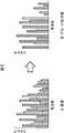
図2は、原音とデコード出力音の周波数特性(振幅特性)を模式的に示す図である。 FIG. 2 is a diagram schematically showing frequency characteristics (amplitude characteristics) of the original sound and the decoded output sound.
図2Aは、原音の周波数特性を示しており、図2Bは、デコード出力音の周波数特性を示している。 FIG. 2A shows the frequency characteristics of the original sound, and FIG. 2B shows the frequency characteristics of the decoded output sound.
図1で説明したように、原音の符号化では、原音の一部の周波数成分がマスキング効果を利用して間引かれるため、その符号化によって得られる符号化データを復号したデコード出力音の周波数特性(図2B)は、原音の周波数特性(図2A)から、所々の周波数成分が(歯抜け状に)間引かれた周波数特性になる。 As described with reference to FIG. 1, in the encoding of the original sound, a part of the frequency components of the original sound is thinned out using the masking effect. Therefore, the frequency of the decoded output sound obtained by decoding the encoded data obtained by the encoding The characteristic (FIG. 2B) is a frequency characteristic in which frequency components are thinned out (toothed) from the frequency characteristic of the original sound (FIG. 2A).
デコード出力音は、マスキング効果を利用するとはいえ、原音の一部(所々)の周波数成分が間引かれているため、そのまま聴いたのでは、視聴者が、音質に不満を感じることがある。 Although the decoded output sound uses the masking effect, the frequency component of a part (some places) of the original sound is thinned out, so that the viewer may feel dissatisfied with the sound quality when listening as it is.
視聴者が、音質に不満を感じることを防止するには、デコード出力音に、音質を改善するための、なんらかの音質改善処理を施す必要がある。 In order to prevent the viewer from feeling dissatisfied with the sound quality, it is necessary to perform some sound quality improvement processing for improving the sound quality on the decoded output sound.
図3は、音質改善処理後のデコード出力音の周波数特性を模式的に示す図である。 FIG. 3 is a diagram schematically showing frequency characteristics of the decoded output sound after the sound quality improvement processing.
図3では、デコード出力音の、周波数成分が間引かれた周波数を、例えば、符号化データのコーデック情報(符号化データに含まれる、その符号化データを得るのに行われた符号化に関する情報)から認識するとともに、間引かれた周波数成分の振幅(エネルギー)を、高調波成分やエンベロープ等を考慮して推測し、周波数成分が間引かれた周波数に、図中、斜線を付して示す、振幅が推測された周波数成分(振幅成分)を周波数軸上で補間する音質改善処理が行われている。 In FIG. 3, for example, codec information of encoded data (information related to encoding performed to obtain the encoded data, which is included in the encoded data), is the frequency from which the frequency component of the decoded output sound is thinned. ) And the amplitude (energy) of the thinned frequency component is estimated in consideration of the harmonic component and the envelope, and the frequency components with the thinned frequency component are hatched in the figure. A sound quality improvement process for interpolating on the frequency axis a frequency component (amplitude component) whose amplitude is estimated is shown.
しかしながら、周波数成分が間引かれた周波数を、コーデック情報から認識するのでは、符号化方式ごとに異なるコーデック情報を解釈することが必要になる。 However, in order to recognize the frequency from which the frequency component is thinned out from the codec information, it is necessary to interpret different codec information for each encoding method.
また、間引かれた周波数成分の振幅を、デコード出力音の高調波成分やエンベロープ等を考慮して推測し、周波数軸上で周波数成分を補間する音質改善処理では、音質改善処理後のデコード出力音が、不自然な音になることや、余分な付帯音が付いた音になる等の悪影響が生じることが少なくない。 In addition, in the sound quality improvement process that estimates the amplitude of the thinned frequency component in consideration of the harmonic component and envelope of the decoded output sound and interpolates the frequency component on the frequency axis, the decoded output after the sound quality improvement process It is not uncommon for the sound to have an adverse effect such as an unnatural sound or a sound with an extra incidental sound.
そこで、図1の信号処理部23では、一部の周波数成分が間引かれたデコード出力音の音質を適切に改善する音質改善処理を行う。 Therefore, the
[音質改善装置の構成例] [Configuration example of sound quality improvement device]
図4は、図1の信号処理部23が内蔵する、音質改善処理を行う音質改善装置の構成例を示すブロック図である。 FIG. 4 is a block diagram illustrating a configuration example of a sound quality improvement apparatus that performs sound quality improvement processing, which is built in the
図4において、音質改善装置は、フィルタ部31、アンプ32、及び、加算部33を有する。 In FIG. 4, the sound quality improvement apparatus includes a
デコーダ22(図1)からのデコード出力音は、フィルタ部31と加算部33に供給される。 The decoded output sound from the decoder 22 (FIG. 1) is supplied to the
フィルタ部31は、デコーダ22からのデコード出力音、すなわち、一部(所々)の周波数成分が間引かれたオーディオ信号(リニアPCM(Pulse Code Modulation))を、オールパスフィルタでフィルタリングし、そのフィルタリング結果を、デコード出力音の音質を改善するための改善成分として出力する。フィルタ部31が出力する改善成分は、アンプ32に供給される。 The
アンプ32は、フィルタ部31からの改善成分を、式0<α<1で表される範囲の値のMIX係数であるα倍に増幅(減衰)し、加算部33に供給する。 The amplifier 32 amplifies (attenuates) the improved component from the
加算部33は、デコーダ22からのデコード出力音に、アンプ32からの改善成分を加算することにより、デコード出力音の音質を改善した改善音を生成して出力する。すなわち、加算部33は、デコード出力音と、(α倍された)改善成分とを加算し、その加算結果を、デコード出力音の音質を改善した改善音として出力する。 The adder 33 generates and outputs an improved sound with improved sound quality of the decoded output sound by adding the improved component from the amplifier 32 to the decoded output sound from the
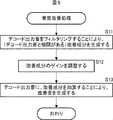
図5は、図4の音質改善装置が行う処理(音質改善処理)を説明するフローチャートである。 FIG. 5 is a flowchart for explaining processing (sound quality improvement processing) performed by the sound quality improvement apparatus of FIG.
ステップS11において、フィルタ部31は、デコーダ22からのデコード出力音を、オールパスフィルタでフィルタリングすることにより、改善成分を生成し、アンプ32に供給して、処理は、ステップS12に進む。 In step S11, the
ステップS12では、アンプ32は、フィルタ部31からの改善成分のゲイン(振幅)を、α倍に調整し、加算部33に供給して、処理は、ステップS13に進む。 In step S <b> 12, the amplifier 32 adjusts the gain (amplitude) of the improvement component from the
ステップS13では、加算部33は、デコーダ22からのデコード出力音に、アンプ32からの改善成分を加算することにより、改善音を生成して出力する。 In step S <b> 13, the adding unit 33 generates and outputs an improved sound by adding the improved component from the amplifier 32 to the decoded output sound from the
[フィルタ部31の構成例] [Configuration Example of Filter Unit 31]
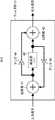
図6は、図4のフィルタ部31の構成例を示すブロック図である。 FIG. 6 is a block diagram illustrating a configuration example of the
図6において、フィルタ部31は、加算部41、遅延部42、加算部43、アンプ44、及び、45を有し、オールパスフィルタを構成している。 In FIG. 6, the
いま、オールパスフィルタのフィルタリングの対象となる(ディジタル)信号を、入力信号といい、オールパスフィルタによる入力信号のフィルタリングにより得られる(ディジタル)信号を、出力信号ということとすると、入力信号は、加算部41に供給される。 Now, a (digital) signal to be filtered by the all-pass filter is called an input signal, and a (digital) signal obtained by filtering the input signal by the all-pass filter is called an output signal. 41.
加算部41は、入力信号と、アンプ45から供給される信号とを加算し、その結果得られる加算値を出力する。加算部41が出力する加算値は、遅延部42とアンプ44に供給される。 The adder 41 adds the input signal and the signal supplied from the amplifier 45, and outputs the added value obtained as a result. The added value output from the adding unit 41 is supplied to the
遅延部42は、例えば、複数のレジスタで構成され、加算部41からの加算値を、遅延部42を構成するレジスタの数であるタップ数nに対応する遅延量(時間)だけ遅延し、遅延信号を出力する。遅延部42が出力する遅延信号は、加算部43とアンプ45に供給される。 The
加算部43は、遅延部42からの遅延信号と、アンプ44から供給される信号とを加算し、その結果得られる加算値を、出力信号として出力する。 The adder 43 adds the delay signal from the
アンプ44は、加算部41からの加算値を、g(0<g<1)倍に増幅(減衰)し、加算部43に供給する。 The amplifier 44 amplifies (attenuates) the added value from the adding unit 41 by g (0 <g <1) times, and supplies the amplified value to the adding unit 43.
アンプ45は、遅延部42からの遅延信号を、-g倍に増幅(減衰)し、加算部41に供給する。 The amplifier 45 amplifies (attenuates) the delayed signal from the
以上のように構成されるフィルタ部31としてのオールパスフィルタは、全周波数帯域の入力信号を通過させ、位相だけを変化させる。したがって、フィルタ部31から出力される出力信号は、例えば、振幅特性が入力信号と同一で、位相特性が入力信号と異なる信号となる。 The all-pass filter as the
[音質改善装置による音質改善処理] [Sound quality improvement processing by sound quality improvement device]
図7は、図4の音質改善装置による音質改善処理を説明する図である。 FIG. 7 is a diagram for explaining sound quality improvement processing by the sound quality improvement apparatus of FIG.
図7Aは、デコード出力音の周波数特性(振幅特性)を、図7Bは、フィルタ部31で得られる改善成分の周波数特性を、図7Cは、加算部33で得られる改善音の周波数特性を、それぞれ、模式的に示している。 7A shows the frequency characteristic (amplitude characteristic) of the decoded output sound, FIG. 7B shows the frequency characteristic of the improvement component obtained by the
音質改善装置では、フィルタ部31において、デコード出力音(図7C)を、オールパスフィルタでフィルタリングする時間軸上の処理により、改善成分が生成される。 In the sound quality improvement apparatus, an improvement component is generated in the
その結果、改善成分として、デコード出力音と相関がある信号(自然な歪み成分)を得ることができる。 As a result, a signal (natural distortion component) correlated with the decoded output sound can be obtained as an improvement component.
そして、音質改善装置では、アンプ32において、改善成分を、1未満のα倍に増幅(減衰)し、加算部33において、デコード出力音に、改善成分を加算することにより、改善音が求められる。 In the sound quality improvement apparatus, the improvement component is obtained by amplifying (attenuating) the improvement component to α times less than 1 in the amplifier 32 and adding the improvement component to the decoded output sound in the adding unit 33. .
すなわち、音質改善装置では、時間軸上で、デコード出力音(図7C)に、僅かな(α倍された)改善成分(図7B)が加算されることによって、図7Cの改善音が生成される。 That is, in the sound quality improvement device, the improvement sound of FIG. 7C is generated by adding a slight (α multiplied) improvement component (FIG. 7B) to the decoded output sound (FIG. 7C) on the time axis. The
ここで、フィルタ部31としてのオールパスフィルタは、全周波数帯域の入力信号を通過させ、位相だけを変化させるので、定常状態では、オールパスフィルタの出力信号である改善成分に、オールパスフィルタの入力信号であるデコード出力音に存在しない周波数成分は、現れない。 Here, the all-pass filter as the
但し、図7Bの(α倍された)改善成分には、デコード出力音に存在しない周波数成分が現れている。これは、過渡現象に起因する。図8を参照して、改善成分に、デコード出力音に存在しない周波数成分が現れることについて説明する。 However, in the improved component (multiplied by α) in FIG. 7B, a frequency component that does not exist in the decoded output sound appears. This is due to a transient phenomenon. With reference to FIG. 8, it will be described that a frequency component that does not exist in the decoded output sound appears in the improvement component.
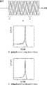
図8は、オールパスフィルタの入力信号と出力信号とを示す図である。 FIG. 8 is a diagram illustrating an input signal and an output signal of the all-pass filter.
図8Aは、オールパスフィルタの入力信号としての、所定の時刻t0から開始される正弦波を示している。FIG. 8A shows a sine wave starting from a predetermined time t0 as an input signal of the all-pass filter.
そして、図8B及び図8Cは、図8Aの入力信号をオールパスフィルタでフィルタリングすることにより得られる出力信号の周波数特性(振幅特性)を示している。 8B and 8C show the frequency characteristics (amplitude characteristics) of the output signal obtained by filtering the input signal of FIG. 8A with an all-pass filter.
但し、図8Bは、正弦波が開始された時刻t0の直後の、出力信号に過渡現象が生じている区間である過渡区間b1の入力信号をフィルタリングしたときの出力信号の周波数特性を示している。However, FIG. 8B, immediately after time t0 when the sine wave is started, shows the frequency characteristic of the output signal when the filter input signal transient interval b1 is an interval in which transient occurs to the output signal Yes.
また、図8Cは、正弦波の開始後、出力信号が定常状態になっている区間である定常区間b2の入力信号をフィルタリングしたときの出力信号の周波数特性を示している。 FIG. 8C shows the frequency characteristics of the output signal when the input signal in the stationary section b2, which is the section in which the output signal is in the steady state, is filtered after the sine wave starts.
図8Bの過渡区間b1の出力信号については、正弦波の周波数成分が歪んでいることを確認することができ、図8Cの定常区間b2の出力信号については、正弦波の周波数成分に歪がないことを確認することができる。 It can be confirmed that the frequency component of the sine wave is distorted for the output signal in the transient section b1 in FIG. 8B, and the frequency component of the sine wave is not distorted in the output signal in the steady section b2 in FIG. 8C. I can confirm that.
以上のように、過渡区間b1においては、図8Bに示すように、正弦波の周波数成分が歪み、正弦波の周波数成分の他に、その正弦波の周波数成分の周辺の周波数の周波数成分が現れる。 As described above, in the transient section b1, as shown in FIG. 8B, the frequency component of the sine wave is distorted, and in addition to the frequency component of the sine wave, frequency components of frequencies around the frequency component of the sine wave appear. .
そして、この正弦波の周波数成分の周辺の周波数に現れる周波数成分が、改善成分として、デコード出力音の音質の改善に大きく寄与する。 A frequency component appearing in the frequency around the frequency component of the sine wave greatly contributes to improvement of the sound quality of the decoded output sound as an improvement component.
なお、改善成分は、その改善成分を生成するのに、オールパスフィルタでのフィルタリングに用いたデコード出力音に時間的になるべく近いデコード出力音に加算する必要があるため、フィルタ部31としてのオールパスフィルタ(図6)を構成する遅延部42のタップ数nに対応する遅延量は、十分に短い時間である必要がある。 The improvement component needs to be added to the decoded output sound that is as close as possible to the decoded output sound used for filtering by the all-pass filter in order to generate the improved component. Therefore, the all-pass filter as the
このため、遅延部42(図6)の遅延量は、例えば、原音の符号化(ひいては、復号)において、処理の単位となるフレームの長さ以下の時間になっている。 For this reason, the delay amount of the delay unit 42 (FIG. 6) is, for example, a time equal to or shorter than the length of the frame that is a unit of processing in encoding (and consequently decoding) the original sound.
図9は、原音、デコード出力音、及び、改善音を示す波形図である。 FIG. 9 is a waveform diagram showing the original sound, the decoded output sound, and the improved sound.
図9Aは、原音を示し、図9Bは、図9Aの原音を符号化して復号することにより得られるデコード出力音を示している。そして、図9Cは、図9Bのデコード出力音を対象として、図4の音質改善装置で音質改善処理を行うことにより得られる改善音を示している。 FIG. 9A shows the original sound, and FIG. 9B shows a decoded output sound obtained by encoding and decoding the original sound of FIG. 9A. FIG. 9C shows an improved sound obtained by performing the sound quality improvement process on the decoded output sound of FIG. 9B with the sound quality improvement apparatus of FIG.
図9Bのデコード出力音については、図9Aの原音と比較して、付帯音や音の響きに影響するエンベロープが、いわば痩せた状態(音痩せの状態)になっていることを確認することができる。 For the decoded output sound of FIG. 9B, it can be confirmed that the envelope that affects the sound of the incidental sound and sound is in a thin state (sounding state) compared to the original sound of FIG. 9A. it can.
また、図9Cの改善音については、エンベロープが、図9Aの原音に近い状態に修復(復元)されていることを確認することができる。 For the improved sound in FIG. 9C, it can be confirmed that the envelope has been restored (restored) to a state close to the original sound in FIG. 9A.
以上のように、図4の音質改善装置によれば、デコーダ22が出力するデコード出力音を、オールパスフィルタでフィルタリングし、その結果得られる改善成分を、デコード出力音に加算することにより、改善音を生成するので、デコード出力音の音質を、適切に改善することができる。 As described above, according to the sound quality improvement apparatus of FIG. 4, the decoded output sound output from the
すなわち、例えば、周波数軸上で、デコード出力音にエネルギを補間することにより、改善音を生成する場合には、改善音の音のバランスが崩れることや、改善音が不自然な音になることがある。 That is, for example, when improving sound is generated by interpolating energy to the decoded output sound on the frequency axis, the balance of the sound of the improving sound is lost, or the improving sound becomes unnatural sound. There is.
一方、デコード出力音を、オールパスフィルタでフィルタリングすることにより得られる改善成分を、(時間軸上で)デコード出力音に加算する場合には、改善音の音のバランスが崩れることがなく、また、改善音が不自然な音になることもない。 On the other hand, when the improvement component obtained by filtering the decoded output sound with the all-pass filter is added to the decoded output sound (on the time axis), the balance of the improved sound is not lost, Improvement sound does not become unnatural sound.
また、図4の音質改善装置によれば、図9で説明したように、改善音のエンベロープが、原音に近い状態に修復されるので、原音の符号化時に行われる一部の周波数成分の間引きによって生じる音痩せに起因する、ボーカル等の、いわゆる引っかかりを緩和することができる。 Further, according to the sound quality improvement apparatus of FIG. 4, as described in FIG. 9, since the envelope of the improved sound is restored to a state close to the original sound, a part of the frequency components thinned out at the time of encoding the original sound is thinned out. It is possible to relieve so-called catches such as vocals caused by sound fading caused by sound.
さらに、改善音のエンベロープが修復される(整えられる)ことにより、音像の定位が明確になり、原音に近い、広い音場(特にサラウンド)を得ることができる。 Further, by repairing (or adjusting) the envelope of the improved sound, the localization of the sound image becomes clear, and a wide sound field (especially surround) close to the original sound can be obtained.
また、図4の音質改善装置による音質改善処理は、負荷が軽く、迅速に実行することができる。すなわち、図4の音質改善装置を、例えば、アナログ・デバイセズ社製のプロセッサADSP-21488を用いて構成した場合には、約4MIPS(Million Instructions Per Second)程度で、音質改善処理を実行することができ、音質改善処理に必要なメモリは、約3kバイト程度の容量のメモリで済む。 Also, the sound quality improvement processing by the sound quality improvement apparatus of FIG. 4 is light in load and can be executed quickly. That is, when the sound quality improvement apparatus in FIG. 4 is configured using, for example, the ADSP-21488 processor manufactured by Analog Devices, the sound quality improvement processing can be executed with about 4 MIPS (Million Instructions Per Second). The memory required for sound quality improvement processing can be about 3k bytes.
さらに、図4の音質改善装置による音質改善処理は、コーデック情報を用いずに行われ、また、デコーダ22の後段で行われる時間軸上のポストプロセッシング(後処理)であるため、原音の符号化方式によらず、一部(所々)の周波数成分が間引かれたデコード出力音を処理することができる。 Furthermore, since the sound quality improvement processing by the sound quality improvement apparatus in FIG. 4 is performed without using the codec information and is post-processing (post-processing) on the time axis performed after the
[音質改善装置の他の構成例] [Other examples of sound quality improvement devices]
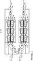
図10は、L(Left)及びR(Right)チャンネルの2チャンネルのデコード出力音を処理する音質改善装置の第1の構成例を示すブロック図である。 FIG. 10 is a block diagram illustrating a first configuration example of a sound quality improvement apparatus that processes 2-channel decoded output sound of L (Left) and R (Right) channels.
図10において、音質改善装置は、Lチャンネルのデコード出力音(以下、Lチャンネルデコード出力音ともいう)と、Rチャンネルのデコード出力音(以下、Rチャンネルデコード出力音ともいう)とのそれぞれに、音質改善処理を施し、Lチャンネルデコード出力音の音質を改善したLチャンネル改善音と、Rチャンネルデコード出力音の音質を改善したRチャンネル改善音とを出力する。 In FIG. 10, the sound quality improving apparatus performs an L channel decode output sound (hereinafter also referred to as an L channel decode output sound) and an R channel decode output sound (hereinafter also referred to as an R channel decode output sound). Performs sound quality improvement processing to output L channel improved sound with improved sound quality of L channel decoded output sound and R channel improved sound with improved sound quality of R channel decoded output sound.
図10の音質改善装置では、カスケードに接続された3つのオールパスフィルタが、LチャンネルとRチャンネルそれぞれについて、2系統設けられ、LチャンネルをRチャンネルにクロストークさせるパスと、RチャンネルをLチャンネルにクロストークさせるパスとが、(Lチャンネル及びRチャンネルに)非対象に設けられている。 In the sound quality improvement apparatus of FIG. 10, three all-pass filters connected in cascade are provided for each of the L channel and the R channel, a path for crosstalking the L channel to the R channel, and the R channel to the L channel. A crosstalk path is provided non-objectively (for the L channel and the R channel).
したがって、図10の音質改善装置では、Lチャンネルデコード出力音とRチャンネルデコード出力音とに、非対称の処理が施される。 Therefore, in the sound quality improvement apparatus of FIG. 10, asymmetric processing is performed on the L channel decoded output sound and the R channel decoded output sound.
すなわち、図10において、音質改善装置は、アンプ51L及び51R、加算部52L及び52R、オールパスフィルタ53L1,53R1,53L2,53R2,53L3,53R3,54L1,54R1,54L2,54R2,54L3、及び、54R3、加算部55L及び55R、アンプ56L及び56R、並びに、加算部57L及び57Rを有する。That is, in FIG. 10, the sound quality improvement apparatus includes
図10の音質改善装置において、Lチャンネルデコード出力音は、アンプ51R、加算部52L、オールパスフィルタ53L1、及び、加算部57Lに供給され、Rチャンネルデコード出力音は、アンプ51L、加算部52R、オールパスフィルタ53R1、及び、加算部57Rに供給される。In the sound quality improvement apparatus of FIG. 10, the L channel decoded output sound is supplied to the
アンプ51Lは、Rチャンネルデコード出力音を、K(例えば、0.1)倍に増幅し、加算部52Lに供給する。 The
加算部52Lは、Lチャンネルデコード出力音に、アンプ51LからのRチャンネルデコード出力音を加算し、その結果得られる加算値を、オールパスフィルタ54L1ないし54L3がカスケードに接続されたオールパスフィルタブロック54Lの最初の段のオールパスフィルタ54L1に供給する。The
オールパスフィルタ53L1は、オールパスフィルタ53L1ないし53L3がカスケードに接続されたオールパスフィルタブロック53Lの最初の段のオールパスフィルタであり、Lチャンネルデコード出力音をフィルタリングして、そのフィルタリング結果を、後段のオールパスフィルタ53L2に供給する。The all-
ここで、オールパスフィルタ53L1ないし53L3,53R1ないし53R3,54L1ないし54L3、及び、54R1ないし54R3は、図6に示したフィルタ部31としてのオールパスフィルタと同様に構成される。Here, the all-
また、図10において、オールパスフィルタ53Liを表すブロックに記載されている(N#j,G#j)は、オールパスフィルタ53Liを構成する遅延部42(図6)の遅延量nが、N#jで、アンプ44(及びアンプ45)のゲインgが、G#jであることを表す。Also, in FIG. 10, (N # j, G # j) described in the block representing the all-
オールパスフィルタ53Ri,54Li、及び、54Riを表すブロックについても、同様である。The same applies to blocks representing all-
したがって、図10において、オールパスフィルタ53Liの遅延量n及びゲインgは、それぞれ、N#i及びG#iであり、オールパスフィルタ54Riの遅延量n及びゲインgと一致している。Accordingly, in FIG. 10, the delay amount n and the gain g of the all-
また、図10において、オールパスフィルタ54Liの遅延量n及びゲインgは、それぞれ、N#(i+3)及びG#(i+3)であり、オールパスフィルタ53Riの遅延量n及びゲインgと一致している。In FIG. 10, the delay amount n and the gain g of the all-
オールパスフィルタ53L2は、前段のオールパスフィルタ53L1からのフィルタリング結果をフィルタリングし、そのフィルタリング結果を、後段のオールパスフィルタ53L3に供給する。The all-
オールパスフィルタ53L3は、前段のオールパスフィルタ53L2からのフィルタリング結果をフィルタリングし、そのフィルタリング結果を、加算部55Lに供給する。The all-
オールパスフィルタ54L1は、加算部52Lからの加算値をフィルタリングして、そのフィルタリング結果を、後段のオールパスフィルタ54L2に供給する。The all-
オールパスフィルタ54L2は、前段のオールパスフィルタ54L1からのフィルタリング結果をフィルタリングし、そのフィルタリング結果を、後段のオールパスフィルタ54L3に供給する。All-
オールパスフィルタ54L3は、前段のオールパスフィルタ54L2からのフィルタリング結果をフィルタリングし、そのフィルタリング結果を、加算部55Lに供給する。All-
加算部55Lは、オールパスフィルタ53L3からのフィルタリング結果と、オールパスフィルタ54L3からのフィルタリング結果とを加算し、その結果得られる加算値を、改善成分として、アンプ56Lに供給する。Adding
アンプ56Lは、加算部55Lからの改善成分を、α(例えば、0.1)倍に増幅し、加算部57Lに供給する。 The
加算部57Lは、アンプ51Lからの改善成分を、Lチャンネルデコード出力音に加算し、その結果得られる加算値を、Lチャンネル改善音として出力する。 The
ここで、以上のアンプ51L、加算部52L、オールパスフィルタブロック53L(を構成するオールパスフィルタ53L1ないし53L3)、オールパスフィルタブロック54L(を構成するオールパスフィルタ54L1ないし54L3)、及び、加算部55Lが、図4のフィルタ部31に相当する。Here,
いま、フィルタ部31に相当する加算部52L、オールパスフィルタブロック53L,54L、及び、加算部55Lを、相当フィルタ部ということとすると、相当フィルタ部では、Lチャンネルデコード出力音、及び、Rチャンネルデコード出力音のうちの一方のチャンネルのオーディオ信号としてのLチャンネルデコード出力音が、オールパスフィルタブロック53Lでフィルタリングされる。 Now, assuming that the
また、相当フィルタ部では、加算部52Lにおいて、Lチャンネルデコード出力音に、他方のチャンネルのオーディオ信号としての、アンプ51Lが出力するRチャンネルデコード出力音を加算することによりクロストークさせ、その結果得られるクロストーク信号が、オールパスフィルタブロック54Lでフィルタリングされる。 Further, in the equivalent filter unit, the
そして、加算部55Lにおいて、オールパスフィルタブロック53LでのLチャンネルデコード出力音のフィルタリング結果と、オールパスフィルタブロック53Lでのクロストーク信号のフィルタリング結果とが加算され、その結果得られる加算値が、Lチャンネルデコード出力音の改善成分として出力される。 Then, in the
アンプ51R、加算部52R、オールパスフィルタブロック53Rを構成するオールパスフィルタ53R1ないし53R3、オールパスフィルタブロック54Rを構成するオールパスフィルタ54R1ないし54R3、加算部55R、アンプ56R、及び、加算部57Rでは、Lチャンネルデコード出力音に代えて、Rチャンネルデコード出力音が用いられるとともに、Rチャンネルデコード出力音に代えて、Lチャンネルデコード出力音が用いられることを除けば、アンプ51Lないし加算部57Lと、それぞれ同様の処理が行われる。
なお、図10では、Lチャンネルデコード出力音をフィルタリングするオールパスフィルタブロック53Lを構成するオールパスフィルタ53Liの遅延量n及びゲインgが、N#i及びG#iになっているとともに、Lチャンネルデコード出力音にRチャンネルデコード出力音をクロストークさせたクロストーク信号をフィルタリングするオールパスフィルタブロック54Lを構成するオールパスフィルタ54Liの遅延量n及びゲインgが、N#(i+3)及びG#(i+3)になっている。In FIG. 10, the delay amount n and the gain g of the all-
一方、Rチャンネルデコード出力音をフィルタリングするオールパスフィルタブロック53Rを構成するオールパスフィルタ53Riの遅延量n及びゲインgは、N#(i+3)及びG#(i+3)になっているとともに、Rチャンネルデコード出力音にLチャンネルデコード出力音をクロストークさせたクロストーク信号をフィルタリングするオールパスフィルタブロック54Rを構成するオールパスフィルタ54Riの遅延量n及びゲインgは、N#i及びG#iになっている。On the other hand, the delay amount n and the gain g of the all-
以上のように、図10では、Lチャンネルデコード出力音をフィルタリングするオールパスフィルタブロック53Lを構成するオールパスフィルタ53Liの遅延量n及びゲインgと、Rチャンネルデコード出力音をフィルタリングするオールパスフィルタブロック53Rを構成するオールパスフィルタ53Riの遅延量n及びゲインgとが、一致していない。As described above, in FIG. 10, the delay amount n and gain g of the all-
さらに、図10では、Lチャンネルデコード出力音にRチャンネルデコード出力音をクロストークさせたクロストーク信号をフィルタリングするオールパスフィルタブロック54Lを構成するオールパスフィルタ54Liの遅延量n及びゲインgと、Rチャンネルデコード出力音にLチャンネルデコード出力音をクロストークさせたクロストーク信号をフィルタリングするオールパスフィルタブロック54Rを構成するオールパスフィルタ54Riの遅延量n及びゲインgも、一致していない。Further, in FIG. 10, the delay amount n and gain g of the all-
したがって、図10では、Lチャンネルデコード出力音と、Rチャンネルデコード出力音とに、非対称の処理(ここでは、遅延量n及びゲインgが一致していないオールパスフィルタによるフィルタリングの処理)が施される。 Therefore, in FIG. 10, the L channel decoded output sound and the R channel decoded output sound are subjected to asymmetric processing (here, filtering processing using an all-pass filter in which the delay amount n and the gain g do not match). .
ここで、ゲインG#1,G#2、及び、G#3としては、例えば、それぞれ、0.6484,0.6016、及び、0.5391を採用することができ、ゲインG#4,G#5、及び、G#6としては、例えば、それぞれ、ゲインG#1,G#2、及び、G#3と同一の値を採用することができる。 Here, for example, 0.6484, 0.6016, and 0.5391 can be adopted as the gains G # 1,
また、遅延量(タップ数)N#1,N#2,及び、N#3としては、例えば、それぞれ、97タップ(サンプル)、61タップ、及び、43タップを採用することができ、遅延量N#4,N#5、及びN#6としては、例えば、それぞれ、89タップ、67タップ、及び、41タップを採用することができる。 Further, as the delay amount (number of taps) N # 1,
なお、AACの1フレームは、1024サンプルであり、mp3の1フレームは、576サンプルである。また、AC3の1フレームは、DVDの標準レートである48kHz/384kbpsで、768サンプルであり、DVDで使用されるdtsの1フレームは、512サンプルである。 One frame of AAC is 1024 samples, and one frame of mp3 is 576 samples. One frame of AC3 is 768 samples at 48 kHz / 384 kbps which is the standard rate of DVD, and one frame of dts used in DVD is 512 samples.
遅延量N#1,N#2,及び、N#3として、例えば、上述の97タップ、61タップ、及び、43タップを採用した場合、オールパスフィルタブロック53Lや54Rの遅延量の総和N#1+N#2+N#3は、符号化方式によらず、フレームの長さ以下の時間になる。 For example, when the above-described 97 taps, 61 taps, and 43 taps are employed as the delay amounts N # 1,
同様に、遅延量N#4,N#5、及びN#6として、例えば、上述の89タップ、67タップ、及び、41タップを採用した場合、オールパスフィルタブロック54Lや53Rの遅延量の総和N#4+N#5+N#6は、符号化方式によらず、フレームの長さ以下の時間になる。 Similarly, when the above-described 89 taps, 67 taps, and 41 taps are adopted as the delay amounts
なお、オールパスフィルタブロック53L,53R,54L、及び、54Rの遅延量及びゲインは、上述した値に限定されるものではない。アンプ51L及び51RのゲインK、並びに、アンプ56L及び56Rのゲインαについても、同様である。 Note that the delay amount and gain of the all-pass filter blocks 53L, 53R, 54L, and 54R are not limited to the above-described values. The same applies to the gain K of the
また、図10では、Lチャンネルデコード出力音とRチャンネルデコード出力音のうちの、一方を他方にクロストークさせることとしたが、クロストークは、必須ではない。 In FIG. 10, one of the L channel decode output sound and the R channel decode output sound is crosstalked to the other, but the crosstalk is not essential.
さらに、図10では、Lチャンネルデコード出力音と、Rチャンネルデコード出力音とに、非対称の処理を施すこととしたが、Lチャンネルデコード出力音と、Rチャンネルデコード出力音とには、対称の処理(同一の処理)を施すことができる。 Further, in FIG. 10, the L channel decode output sound and the R channel decode output sound are subjected to asymmetric processing, but the L channel decode output sound and the R channel decode output sound are processed symmetrically. (Same processing) can be performed.
また、図10では、オールパスフィルタブロック53L,53R,54L、及び、54Rを、3つのオールパスフィルタをカスケードに接続することにより構成することとしたが、オールパスフィルタブロック53L,53R,54L、及び、54Rは、1つのオールパスフィルタで構成することもできるし、3つ以外の複数のオールパスフィルタをカスケードに接続することにより構成することもできる。 In FIG. 10, the all-pass filter blocks 53L, 53R, 54L, and 54R are configured by connecting three all-pass filters in cascade, but the all-pass filter blocks 53L, 53R, 54L, and 54R are configured. Can be configured by one all-pass filter, or can be configured by connecting a plurality of all-pass filters other than three in cascade.
オールパスフィルタブロック53Lを(オールパスフィルタ53R,54L、及び、54Rについても、同様)、複数のオールパスフィルタをカスケードに接続することにより構成した場合には、過渡期間において、歪みがより一様に広がった改善成分を得ることができる。 When the all-
図11は、図10のオールパスフィルタブロック53Lを構成するオールパスフィルタ53Liの出力の周波数特性(振幅特性)を示す図である。FIG. 11 is a diagram showing the frequency characteristic (amplitude characteristic) of the output of the all-
すなわち、図11Aは、オールパスフィルタブロック53Lを構成する最初の段のオールパスフィルタ53L1の出力の周波数特性を、図11Bは、2段目のオールパスフィルタ53L2の出力の周波数特性を、図11Cは、最後の段のオールパスフィルタ53L3の出力の周波数特性を、それぞれ示している。That is, FIG. 11A, the first frequency characteristic of the output of the all-
オールパスフィルタ53L1への入力は、図8Aに示した所定の時刻t0から開始される正弦波であり、図11の周波数特性は、いずれも、過渡区間b1の周波数特性を表している。The input to the all-
図11から、後段のオールパスフィルタの出力ほど、正弦波の周波数成分の歪みが一様になっていること(正弦波の周波数成分の周辺の周波数に、より細かな変化の周波数成分が現れること)を確認することができる。 From FIG. 11, the distortion of the frequency component of the sine wave becomes more uniform as the output of the subsequent all-pass filter (the frequency component of a finer change appears in the frequency around the frequency component of the sine wave). Can be confirmed.
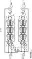
図12は、L及びRチャンネルの2チャンネルのデコード出力音を処理する音質改善装置の第2の構成例を示すブロック図である。 FIG. 12 is a block diagram illustrating a second configuration example of the sound quality improvement apparatus that processes the two-channel decoded output sound of the L and R channels.
なお、図中、図10の場合と対応する部分については、同一の符号を付してあり、以下では、その説明は、適宜省略する。 In the figure, portions corresponding to those in FIG. 10 are denoted by the same reference numerals, and description thereof will be omitted as appropriate.
図12の音質改善装置は、アンプ51Lないし加算部55L、及び、57L、並びに、アンプ51Rないし加算部55R、及び、57Rを有する点で、図10の場合と共通する。 The sound quality improvement apparatus of FIG. 12 is common to the case of FIG. 10 in that it includes an
但し、図12の音質改善装置は、加算部55Lの後段のアンプ56Lに代えて、オールパスフィルタブロック53Lの前段に、アンプ61Lが設けられているとともに、オールパスフィルタブロック54Lの前段に、アンプ62Lが設けられている点、並びに、加算部55Rの後段のアンプ56Rに代えて、オールパスフィルタブロック53Rの前段に、アンプ61Rが設けられているとともに、オールパスフィルタブロック54Rの前段に、アンプ62Rが設けられている点において、図10の場合と相違する。 However, in the sound quality improvement apparatus of FIG. 12, an
アンプ61L及び62Rは、そこに入力される信号を、α1倍して出力する。 The
アンプ62L及び61Rは、そこに入力される信号を、α2倍して出力する。 The
アンプ61L及び62Rのゲインα1と、アンプ62L及び61Rのゲインα2とが、αで一致する場合には、図12の音質改善装置は、図10の音質改善装置と、実質的に等価な装置となる。 When the gain α1 of the
図12の音質改善装置では、Lチャンネルについて、Lチャンネルデコード出力音と、Lチャンネルデコード出力音にRチャンネルデコード出力音をクロストークさせたクロストーク信号とのそれぞれが、改善成分に与える影響を、ゲインα1及びα2によって、個別に調整することができる。Rチャンネルについても、同様である。 In the sound quality improvement apparatus of FIG. 12, for the L channel, each of the L channel decoded output sound and the crosstalk signal obtained by crosstalking the R channel decoded output sound with the R channel decoded output sound has an influence on the improvement component. The gains α1 and α2 can be adjusted individually. The same applies to the R channel.
図13は、L及びRチャンネルの2チャンネルのデコード出力音を処理する音質改善装置の第3の構成例を示すブロック図である。 FIG. 13 is a block diagram illustrating a third configuration example of the sound quality improvement apparatus that processes the decoded output sound of the two channels of the L and R channels.
なお、図中、図10及び図12の場合と対応する部分については、同一の符号を付してあり、以下では、その説明は、適宜省略する。 In the figure, portions corresponding to those in FIGS. 10 and 12 are denoted by the same reference numerals, and description thereof will be appropriately omitted below.
図13の音質改善装置は、アンプ51Lないし加算部55L、加算部57L、アンプ61L、及び、62L、並びに、アンプ51Rないし加算部55R、加算部57R、アンプ61R、及び、62Rを有する点で、図12の場合と共通する。 The sound quality improvement apparatus in FIG. 13 includes an
そして、図13の音質改善装置は、加算部55Lの後段に、図10のアンプ56Lが設けられている点、並びに、加算部55Rの後段に、図10のアンプ56Rが設けられている点において、図12の場合と相違する。 The sound quality improvement apparatus of FIG. 13 is provided with the
したがって、図13の音質改善装置では、Lチャンネルについて、図12の場合と同様に、Lチャンネルデコード出力音と、Lチャンネルデコード出力音にRチャンネルデコード出力音をクロストークさせたクロストーク信号とのそれぞれが、改善成分に与える影響を、アンプ61Lのゲインα1及びアンプ62Lのα2によって、個別に調整することができる。 Therefore, in the sound quality improvement apparatus of FIG. 13, for the L channel, as in the case of FIG. 12, the L channel decoded output sound and the crosstalk signal obtained by crosstalking the R channel decoded output sound with the R channel decoded output sound. The influence of each on the improvement component can be individually adjusted by the gain α1 of the
さらに、図13の音質改善装置では、Lチャンネルについて、改善成分が、Lチャンネル改善音に与える影響を、アンプ56Lのゲインαによって、調整することができる。 Further, in the sound quality improvement apparatus of FIG. 13, the influence of the improvement component on the L channel improvement sound can be adjusted for the L channel by the gain α of the
Rチャンネルについても、同様である。 The same applies to the R channel.
図14は、L及びRチャンネルの2チャンネルのデコード出力音を処理する音質改善装置の第4の構成例を示すブロック図である。 FIG. 14 is a block diagram illustrating a fourth configuration example of the sound quality improvement apparatus that processes the decoded output sound of the two channels of the L and R channels.
なお、図中、図13の場合と対応する部分については、同一の符号を付してあり、以下では、その説明は、適宜省略する。 In the figure, portions corresponding to those in FIG. 13 are denoted by the same reference numerals, and description thereof will be omitted below as appropriate.
図14の音質改善装置は、アンプ51Lないし加算部57L、アンプ61L、及び、62L、並びに、アンプ51R、オールパスフィルタブロック53Rないし加算部57R、アンプ61R、及び、62Rを有する点で、図13の場合と共通する。 The sound quality improvement apparatus in FIG. 14 includes an
但し、図14の音質改善装置は、アンプ62Rの前段の加算部52Rに代えて、加算部71Rが、アンプ61Rの前段に設けられている点で、図13の場合と相違する。 However, the sound quality improvement apparatus of FIG. 14 is different from the case of FIG. 13 in that an
以上のように、図14では、アンプ62Rの前段の加算部52Rに代えて、加算部71Rが、アンプ61Rの前段に設けられているため、Lチャンネル及びRチャンネルについて、図10で説明した非対称の処理(遅延量n及びゲインgが一致していないオールパスフィルタによるフィルタリングの処理)ではなく、対称の処理が行われる。 As described above, in FIG. 14, since the
図15は、L及びRチャンネルの2チャンネルのデコード出力音を処理する音質改善装置の第5の構成例を示すブロック図である。 FIG. 15 is a block diagram illustrating a fifth configuration example of the sound quality improvement apparatus that processes the 2-channel decoded output sound of the L and R channels.
なお、図中、図13の場合と対応する部分については、同一の符号を付してあり、以下では、その説明は、適宜省略する。 In the figure, portions corresponding to those in FIG. 13 are denoted by the same reference numerals, and description thereof will be omitted below as appropriate.
図15の音質改善装置は、アンプ51Lないし加算部57L、アンプ61L、及び、62L、並びに、アンプ51Rないし加算部57R、アンプ61R、及び、62Rを有する点で、図13の場合と共通する。 The sound quality improvement apparatus of FIG. 15 is common to the case of FIG. 13 in that it includes an
そして、図15の音質改善装置は、加算部71L及びアンプ81Lが、アンプ61Lの前段に設けられている点、並びに、加算部71R及びアンプ81Rが、アンプ61Rの前段に設けられている点で、図13の場合と相違する。 In the sound quality improvement apparatus of FIG. 15, the
図15の音質改善装置では、アンプ81Lにおいて、Rチャンネルデコード出力音がK1倍され、加算部71Lに供給される。加算部71Lでは、アンプ81LからのRチャンネルデコード出力音を、Lチャンネルデコード出力音に加算することによりクロストークさせ、その結果得られるクロストーク信号が、アンプ61Lを介して、オールパスフィルタブロック53Lに供給される。 In the sound quality improvement apparatus in FIG. 15, the
また、アンプ51Lにおいて、Rチャンネルデコード出力音がK2倍され、加算部52Lに供給される。加算部52Lでは、アンプ51LからのRチャンネルデコード出力音を、Lチャンネルデコード出力音に加算することによりクロストークさせ、その結果得られるクロストーク信号が、アンプ62Lを介して、オールパスフィルタブロック54Lに供給される。 In the
一方、アンプ81Rでは、Lチャンネルデコード出力音がK2倍され、加算部71Rに供給される。加算部71Rでは、アンプ81RからのLチャンネルデコード出力音を、Rチャンネルデコード出力音に加算することによりクロストークさせ、その結果得られるクロストーク信号が、アンプ61Rを介して、オールパスフィルタブロック53Rに供給される。 On the other hand, in the amplifier 81R, the L channel decoded output sound is multiplied by K2 and supplied to the
また、アンプ51Rにおいて、Lチャンネルデコード出力音がK1倍され、加算部52Rに供給される。加算部52Rでは、アンプ51RからのLチャンネルデコード出力音を、Rチャンネルデコード出力音に加算することによりクロストークさせ、その結果得られるクロストーク信号が、アンプ62Rを介して、オールパスフィルタブロック54Rに供給される。 In the
以下、図15の音質改善装置では、図10の場合と同様の処理が行われる。 Hereinafter, in the sound quality improvement apparatus in FIG. 15, processing similar to that in FIG. 10 is performed.
[本技術を適用したコンピュータの説明] [Description of computer to which this technology is applied]
次に、上述した一連の処理は、ハードウェアにより行うこともできるし、ソフトウェアにより行うこともできる。一連の処理をソフトウェアによって行う場合には、そのソフトウェアを構成するプログラムが、汎用のコンピュータ等にインストールされる。 Next, the series of processes described above can be performed by hardware or software. When a series of processing is performed by software, a program constituting the software is installed in a general-purpose computer or the like.
そこで、図16は、上述した一連の処理を実行するプログラムがインストールされるコンピュータの一実施の形態の構成例を示している。 Therefore, FIG. 16 shows a configuration example of an embodiment of a computer in which a program for executing the series of processes described above is installed.
プログラムは、コンピュータに内蔵されている記録媒体としてのハードディスク105やROM103に予め記録しておくことができる。 The program can be recorded in advance on a
あるいはまた、プログラムは、リムーバブル記録媒体111に格納(記録)しておくことができる。このようなリムーバブル記録媒体111は、いわゆるパッケージソフトウエアとして提供することができる。ここで、リムーバブル記録媒体111としては、例えば、フレキシブルディスク、CD-ROM(Compact Disc Read Only Memory),MO(Magneto Optical)ディスク,DVD(Digital Versatile Disc)、磁気ディスク、半導体メモリ等がある。 Alternatively, the program can be stored (recorded) in the
なお、プログラムは、上述したようなリムーバブル記録媒体111からコンピュータにインストールする他、通信網や放送網を介して、コンピュータにダウンロードし、内蔵するハードディスク105にインストールすることができる。すなわち、プログラムは、例えば、ダウンロードサイトから、ディジタル衛星放送用の人工衛星を介して、コンピュータに無線で転送したり、LAN(Local Area Network)、インターネットといったネットワークを介して、コンピュータに有線で転送することができる。 In addition to installing the program from the
コンピュータは、CPU(Central Processing Unit)102を内蔵しており、CPU102には、バス101を介して、入出力インタフェース110が接続されている。 The computer incorporates a CPU (Central Processing Unit) 102, and an input /
CPU102は、入出力インタフェース110を介して、ユーザによって、入力部107が操作等されることにより指令が入力されると、それに従って、ROM(Read Only Memory)103に格納されているプログラムを実行する。あるいは、CPU102は、ハードディスク105に格納されたプログラムを、RAM(Random Access Memory)104にロードして実行する。 The
これにより、CPU102は、上述したフローチャートにしたがった処理、あるいは上述したブロック図の構成により行われる処理を行う。そして、CPU102は、その処理結果を、必要に応じて、例えば、入出力インタフェース110を介して、出力部106から出力、あるいは、通信部108から送信、さらには、ハードディスク105に記録等させる。 Thus, the
なお、入力部107は、キーボードや、マウス、マイク等で構成される。また、出力部106は、LCD(Liquid Crystal Display)やスピーカ等で構成される。 The
ここで、本明細書において、コンピュータがプログラムに従って行う処理は、必ずしもフローチャートとして記載された順序に沿って時系列に行われる必要はない。すなわち、コンピュータがプログラムに従って行う処理は、並列的あるいは個別に実行される処理(例えば、並列処理あるいはオブジェクトによる処理)も含む。 Here, in the present specification, the processing performed by the computer according to the program does not necessarily have to be performed in time series in the order described as the flowchart. That is, the processing performed by the computer according to the program includes processing executed in parallel or individually (for example, parallel processing or object processing).
また、プログラムは、1のコンピュータ(プロセッサ)により処理されるものであっても良いし、複数のコンピュータによって分散処理されるものであっても良い。さらに、プログラムは、遠方のコンピュータに転送されて実行されるものであっても良い。 Further, the program may be processed by one computer (processor) or may be distributedly processed by a plurality of computers. Furthermore, the program may be transferred to a remote computer and executed.
なお、本技術の実施の形態は、上述した実施の形態に限定されるものではなく、本技術の要旨を逸脱しない範囲において種々の変更が可能である。 The embodiments of the present technology are not limited to the above-described embodiments, and various modifications can be made without departing from the gist of the present technology.
また、本技術は、以下のような構成をとることもできる。 Moreover, this technique can also take the following structures.
[1]
一部の周波数成分が間引かれたオーディオ信号を、オールパスフィルタでフィルタリングし、そのフィルタリング結果を、前記オーディオ信号の音質を改善するための改善成分として出力するフィルタ部と、
前記オーディオ信号に、前記改善成分を加算することにより、前記オーディオ信号の音質を改善した改善音を生成する加算部と
を備える信号処理装置。
[2]
前記オーディオ信号は、原音の一部の周波数成分を間引く処理を、少なくとも行う符号化によって得られる符号化データを復号することにより得られるオーディオ信号である
[1]に記載の信号処理装置。
[3]
前記オールパスフィルタは、信号を遅延する遅延部を有し、
前記遅延部の遅延量は、前記原音の符号化において、処理の単位となるフレームの長さ以下の時間である
[2]に記載の信号処理装置。
[4]
前記フィルタ部は、前記オーディオ信号を、カスケード接続された複数のオールパスフィルタでフィルタリングする
[1]ないし[3]のいずれかに記載の信号処理装置。
[5]
前記フィルタ部は、
2つのチャンネルのオーディオ信号のうちの一方のチャンネルのオーディオ信号を、オールパスフィルタでフィルタリングするとともに、前記一方のチャンネルのオーディオ信号に、他方のチャンネルのオーディオ信号をクロストークさせたクロストーク信号を、オールパスフィルタでフィルタリングし、
前記一方のチャンネルのオーディオ信号のフィルタリング結果と、前記クロストーク信号のフィルタリング結果とを加算し、
前記一方のチャンネルのオーディオ信号のフィルタリング結果と、前記クロストーク信号のフィルタリング結果との加算値を、前記一方のチャンネルのオーディオ信号の音質を改善するための改善成分として出力する
[1]ないし[4]のいずれかに記載の信号処理装置。
[6]
前記2つのチャンネルのオーディオ信号に、非対称の処理を施す
[5]に記載の信号処理装置。
[7]
一部の周波数成分が間引かれたオーディオ信号を、オールパスフィルタでフィルタリングし、そのフィルタリング結果を、前記オーディオ信号の音質を改善するための改善成分として出力し、
前記オーディオ信号に、前記改善成分を加算することにより、前記オーディオ信号の音質を改善した改善音を生成する
ステップを含む信号処理方法。
[8]
一部の周波数成分が間引かれたオーディオ信号を、オールパスフィルタでフィルタリングし、そのフィルタリング結果を、前記オーディオ信号の音質を改善するための改善成分として出力するフィルタ部と、
前記オーディオ信号に、前記改善成分を加算することにより、前記オーディオ信号の音質を改善した改善音を生成する加算部と
して、コンピュータを機能させるためのプログラム。[1]
A filter unit that filters an audio signal from which some frequency components have been thinned out with an all-pass filter and outputs the filtering result as an improved component for improving the sound quality of the audio signal;
A signal processing apparatus comprising: an addition unit that generates an improved sound in which the sound quality of the audio signal is improved by adding the improvement component to the audio signal.
[2]
The signal processing apparatus according to [1], wherein the audio signal is an audio signal obtained by decoding encoded data obtained by encoding at least performing a process of thinning out a part of frequency components of the original sound.
[3]
The all-pass filter has a delay unit that delays a signal;
The signal processing device according to [2], wherein the delay amount of the delay unit is a time equal to or less than a length of a frame that is a unit of processing in encoding the original sound.
[4]
The signal processing device according to any one of [1] to [3], wherein the filter unit filters the audio signal with a plurality of cascaded all-pass filters.
[5]
The filter unit is
The audio signal of one channel of the audio signals of two channels is filtered by an all-pass filter, and the crosstalk signal obtained by crosstalking the audio signal of the other channel with the audio signal of the other channel is allpassed. Filter by filter,
Add the filtering result of the audio signal of the one channel and the filtering result of the crosstalk signal,
The addition value of the filtering result of the audio signal of the one channel and the filtering result of the crosstalk signal is output as an improvement component for improving the sound quality of the audio signal of the one channel [1] to [4] ] The signal processing apparatus in any one of.
[6]
The signal processing device according to [5], wherein asymmetric processing is performed on the audio signals of the two channels.
[7]
The audio signal in which some frequency components are thinned out is filtered by an all-pass filter, and the filtering result is output as an improvement component for improving the sound quality of the audio signal,
A signal processing method including a step of generating an improved sound with improved sound quality of the audio signal by adding the improvement component to the audio signal.
[8]
A filter unit that filters an audio signal from which some frequency components have been thinned out with an all-pass filter and outputs the filtering result as an improved component for improving the sound quality of the audio signal;
A program for causing a computer to function as an adding unit that generates an improved sound in which the sound quality of the audio signal is improved by adding the improvement component to the audio signal.
21 取得部, 22 デコーダ, 23 信号処理部, 24 スピーカ, 25 制御部, 31 フィルタ部, 32 アンプ, 33,41 加算部, 42 遅延部, 43 加算部, 44,45,51L,51R アンプ, 52L,52R 加算部, 53L オールパスフィルタブロック, 53L1ないし53L3 オールパスフィルタ, 53R オールパスフィルタブロック, 53R1ないし53R3 オールパスフィルタ, 54L オールパスフィルタブロック, 54L1ないし54L3 オールパスフィルタ, 54R オールパスフィルタブロック, 54R1ないし54R3 オールパスフィルタ, 55L,55R 加算部, 56L,56R アンプ, 57L,57R 加算部, 61L,61R 62L,62R アンプ, 71L,71R 加算部, 81L,82R アンプ, 101 バス, 102 CPU, 103 ROM, 104 RAM, 105 ハードディスク, 106 出力部, 107 入力部, 108 通信部, 109 ドライブ, 110 入出力インタフェース, 111 リムーバブル記録媒体21 acquisition unit, 22 decoder, 23 signal processing unit, 24 speaker, 25 control unit, 31 filter unit, 32 amplifier, 33, 41 addition unit, 42 delay unit, 43 addition unit, 44, 45, 51L, 51R amplifier, 52L , 52R adder, 53L all pass filter block, 53L1 to 53L3 all pass filter, 53R all pass filter block, 53R1 to 53R3 all pass filter, 54L all pass filter block, 54L1 to 54L3 all pass filter, 54R all pass filter block, 54R1 to 54R3- all pass filter, 55L, 55R adder, 56L, 56R amplifier, 57L, 57R adder, 61L,
Claims (8)
Translated fromJapanese前記オーディオ信号に、前記改善成分を加算することにより、前記オーディオ信号の音質を改善した改善音を生成する加算部と
を備える信号処理装置。A filter unit that filters an audio signal from which some frequency components have been thinned out with an all-pass filter and outputs the filtering result as an improved component for improving the sound quality of the audio signal;
A signal processing apparatus comprising: an addition unit that generates an improved sound in which the sound quality of the audio signal is improved by adding the improvement component to the audio signal.
請求項1に記載の信号処理装置。The signal processing apparatus according to claim 1, wherein the audio signal is an audio signal obtained by decoding encoded data obtained by encoding at least performing a process of thinning out a part of frequency components of the original sound.
前記遅延部の遅延量は、前記原音の符号化において、処理の単位となるフレームの長さ以下の時間である
請求項2に記載の信号処理装置。The all-pass filter has a delay unit that delays a signal;
The signal processing apparatus according to claim 2, wherein the delay amount of the delay unit is a time that is equal to or less than a length of a frame that is a unit of processing in encoding the original sound.
請求項3に記載の信号処理装置。The signal processing apparatus according to claim 3, wherein the filter unit filters the audio signal with a plurality of cascaded all-pass filters.
2つのチャンネルのオーディオ信号のうちの一方のチャンネルのオーディオ信号を、オールパスフィルタでフィルタリングするとともに、前記一方のチャンネルのオーディオ信号に、他方のチャンネルのオーディオ信号をクロストークさせたクロストーク信号を、オールパスフィルタでフィルタリングし、
前記一方のチャンネルのオーディオ信号のフィルタリング結果と、前記クロストーク信号のフィルタリング結果とを加算し、
前記一方のチャンネルのオーディオ信号のフィルタリング結果と、前記クロストーク信号のフィルタリング結果との加算値を、前記一方のチャンネルのオーディオ信号の音質を改善するための改善成分として出力する
請求項3に記載の信号処理装置。The filter unit is
The audio signal of one channel of the audio signals of two channels is filtered by an all-pass filter, and the crosstalk signal obtained by crosstalking the audio signal of the other channel with the audio signal of the other channel is allpassed. Filter by filter,
Add the filtering result of the audio signal of the one channel and the filtering result of the crosstalk signal,
The addition value of the filtering result of the audio signal of the one channel and the filtering result of the crosstalk signal is output as an improvement component for improving the sound quality of the audio signal of the one channel. Signal processing device.
請求項5に記載の信号処理装置。The signal processing apparatus according to claim 5, wherein asymmetric processing is performed on the audio signals of the two channels.
前記オーディオ信号に、前記改善成分を加算することにより、前記オーディオ信号の音質を改善した改善音を生成する
ステップを含む信号処理方法。The audio signal in which some frequency components are thinned out is filtered by an all-pass filter, and the filtering result is output as an improvement component for improving the sound quality of the audio signal,
A signal processing method including a step of generating an improved sound with improved sound quality of the audio signal by adding the improvement component to the audio signal.
前記オーディオ信号に、前記改善成分を加算することにより、前記オーディオ信号の音質を改善した改善音を生成する加算部と
して、コンピュータを機能させるためのプログラム。A filter unit that filters an audio signal from which some frequency components have been thinned out with an all-pass filter and outputs the filtering result as an improved component for improving the sound quality of the audio signal;
A program for causing a computer to function as an adding unit that generates an improved sound in which the sound quality of the audio signal is improved by adding the improvement component to the audio signal.
Priority Applications (6)
| Application Number | Priority Date | Filing Date | Title |
|---|---|---|---|
| JP2011141566AJP2013007944A (en) | 2011-06-27 | 2011-06-27 | Signal processing apparatus, signal processing method, and program |
| EP20120169089EP2541548A3 (en) | 2011-06-27 | 2012-05-23 | Signal processing apparatus, signal processing method, and program |
| US13/488,679US9324334B2 (en) | 2011-06-27 | 2012-06-05 | Signal processing apparatus, signal processing method, and program |
| TW101121109ATW201317984A (en) | 2011-06-27 | 2012-06-13 | Signal processing apparatus, signal processing method, and program |
| KR1020120065596AKR20130007439A (en) | 2011-06-27 | 2012-06-19 | Signal processing apparatus, signal processing method, and program |
| CN2012102093660ACN102855879A (en) | 2011-06-27 | 2012-06-20 | Signal processing apparatus, signal processing method, and program |
Applications Claiming Priority (1)
| Application Number | Priority Date | Filing Date | Title |
|---|---|---|---|
| JP2011141566AJP2013007944A (en) | 2011-06-27 | 2011-06-27 | Signal processing apparatus, signal processing method, and program |
Publications (2)
| Publication Number | Publication Date |
|---|---|
| JP2013007944Atrue JP2013007944A (en) | 2013-01-10 |
| JP2013007944A5 JP2013007944A5 (en) | 2014-07-24 |
Family
ID=46298244
Family Applications (1)
| Application Number | Title | Priority Date | Filing Date |
|---|---|---|---|
| JP2011141566APendingJP2013007944A (en) | 2011-06-27 | 2011-06-27 | Signal processing apparatus, signal processing method, and program |
Country Status (6)
| Country | Link |
|---|---|
| US (1) | US9324334B2 (en) |
| EP (1) | EP2541548A3 (en) |
| JP (1) | JP2013007944A (en) |
| KR (1) | KR20130007439A (en) |
| CN (1) | CN102855879A (en) |
| TW (1) | TW201317984A (en) |
Cited By (2)
| Publication number | Priority date | Publication date | Assignee | Title |
|---|---|---|---|---|
| KR20210135492A (en) | 2019-03-05 | 2021-11-15 | 소니그룹주식회사 | Signal processing apparatus and method, and program |
| US12149911B2 (en) | 2020-02-25 | 2024-11-19 | Sony Group Corporation | Signal processing apparatus, signal processing method, and program |
Families Citing this family (5)
| Publication number | Priority date | Publication date | Assignee | Title |
|---|---|---|---|---|
| CN103377643B (en)* | 2012-04-26 | 2017-02-15 | 富泰华工业(深圳)有限公司 | System and method for adjusting fonts |
| US9361903B2 (en)* | 2013-08-22 | 2016-06-07 | Microsoft Technology Licensing, Llc | Preserving privacy of a conversation from surrounding environment using a counter signal |
| CN105764002B (en) | 2014-12-17 | 2019-10-01 | 南宁富桂精密工业有限公司 | Audio signal processing circuit |
| US10477314B2 (en)* | 2017-03-20 | 2019-11-12 | Bambu Tech, Inc. | Dynamic audio enhancement using an all-pass filter |
| CN113176592B (en)* | 2021-06-30 | 2021-09-07 | 中国人民解放军国防科技大学 | Navigation receiver RF front-end group delay characteristic equalization design method and device |
Citations (4)
| Publication number | Priority date | Publication date | Assignee | Title |
|---|---|---|---|---|
| JP2002041098A (en)* | 2000-07-21 | 2002-02-08 | Kenwood Corp | Frequency thinning device, frequency thinning method and recording medium |
| JP2005530205A (en)* | 2002-06-17 | 2005-10-06 | ドルビー・ラボラトリーズ・ライセンシング・コーポレーション | Audio coding system using spectral hole filling |
| JP2007240823A (en)* | 2006-03-08 | 2007-09-20 | Sharp Corp | Digital data decoding device |
| JP2007271686A (en)* | 2006-03-30 | 2007-10-18 | Yamaha Corp | Audio signal processor |
Family Cites Families (17)
| Publication number | Priority date | Publication date | Assignee | Title |
|---|---|---|---|---|
| TW432806B (en)* | 1996-12-09 | 2001-05-01 | Matsushita Electric Industrial Co Ltd | Audio decoding device |
| WO2006001301A1 (en)* | 2004-06-25 | 2006-01-05 | Evolvable Systems Research Institute Inc. | Parameter adjustment device and parameter adjustment method |
| WO2006040727A2 (en)* | 2004-10-15 | 2006-04-20 | Koninklijke Philips Electronics N.V. | A system and a method of processing audio data to generate reverberation |
| US8243864B2 (en)* | 2004-11-19 | 2012-08-14 | Qualcomm, Incorporated | Noise reduction filtering in a wireless communication system |
| KR100739691B1 (en)* | 2005-02-05 | 2007-07-13 | 삼성전자주식회사 | Apparatus and method for reproducing sound early reflections for sound field effect reproduction |
| CN1719512B (en)* | 2005-07-15 | 2010-09-29 | 北京中星微电子有限公司 | Digital audio frequency reverberation simulation system and method |
| EP1906706B1 (en)* | 2005-07-15 | 2009-11-25 | Panasonic Corporation | Audio decoder |
| KR100739776B1 (en)* | 2005-09-22 | 2007-07-13 | 삼성전자주식회사 | Stereo sound generating method and apparatus |
| JP5141180B2 (en) | 2006-11-09 | 2013-02-13 | ソニー株式会社 | Frequency band expanding apparatus, frequency band expanding method, reproducing apparatus and reproducing method, program, and recording medium |
| JP5010391B2 (en)* | 2007-08-17 | 2012-08-29 | ザインエレクトロニクス株式会社 | Image signal processing device |
| US20090086982A1 (en)* | 2007-09-28 | 2009-04-02 | Qualcomm Incorporated | Crosstalk cancellation for closely spaced speakers |
| DE102008015702B4 (en)* | 2008-01-31 | 2010-03-11 | Fraunhofer-Gesellschaft zur Förderung der angewandten Forschung e.V. | Apparatus and method for bandwidth expansion of an audio signal |
| US20100027799A1 (en)* | 2008-07-31 | 2010-02-04 | Sony Ericsson Mobile Communications Ab | Asymmetrical delay audio crosstalk cancellation systems, methods and electronic devices including the same |
| JP5086436B2 (en)* | 2008-08-07 | 2012-11-28 | 京セラ株式会社 | Power amplifying device and transmitter and communication device using the same |
| US20100066442A1 (en)* | 2008-09-15 | 2010-03-18 | Fenghao Mu | Method and Apparatus for Tunable Current-Mode Filtering |
| US20110065408A1 (en)* | 2009-09-17 | 2011-03-17 | Peter Kenington | Mismatched delay based interference cancellation device and method |
| JP2011141566A (en) | 2011-04-04 | 2011-07-21 | Mitsubishi Chemicals Corp | Image forming method and image forming apparatus |
- 2011
- 2011-06-27JPJP2011141566Apatent/JP2013007944A/enactivePending
- 2012
- 2012-05-23EPEP20120169089patent/EP2541548A3/ennot_activeCeased
- 2012-06-05USUS13/488,679patent/US9324334B2/ennot_activeExpired - Fee Related
- 2012-06-13TWTW101121109Apatent/TW201317984A/enunknown
- 2012-06-19KRKR1020120065596Apatent/KR20130007439A/ennot_activeWithdrawn
- 2012-06-20CNCN2012102093660Apatent/CN102855879A/enactivePending
Patent Citations (4)
| Publication number | Priority date | Publication date | Assignee | Title |
|---|---|---|---|---|
| JP2002041098A (en)* | 2000-07-21 | 2002-02-08 | Kenwood Corp | Frequency thinning device, frequency thinning method and recording medium |
| JP2005530205A (en)* | 2002-06-17 | 2005-10-06 | ドルビー・ラボラトリーズ・ライセンシング・コーポレーション | Audio coding system using spectral hole filling |
| JP2007240823A (en)* | 2006-03-08 | 2007-09-20 | Sharp Corp | Digital data decoding device |
| JP2007271686A (en)* | 2006-03-30 | 2007-10-18 | Yamaha Corp | Audio signal processor |
Cited By (3)
| Publication number | Priority date | Publication date | Assignee | Title |
|---|---|---|---|---|
| KR20210135492A (en) | 2019-03-05 | 2021-11-15 | 소니그룹주식회사 | Signal processing apparatus and method, and program |
| US12170092B2 (en) | 2019-03-05 | 2024-12-17 | Sony Group Corporation | Signal processing device, method, and program |
| US12149911B2 (en) | 2020-02-25 | 2024-11-19 | Sony Group Corporation | Signal processing apparatus, signal processing method, and program |
Also Published As
| Publication number | Publication date |
|---|---|
| US9324334B2 (en) | 2016-04-26 |
| KR20130007439A (en) | 2013-01-18 |
| EP2541548A2 (en) | 2013-01-02 |
| TW201317984A (en) | 2013-05-01 |
| CN102855879A (en) | 2013-01-02 |
| EP2541548A3 (en) | 2014-05-21 |
| US20120328123A1 (en) | 2012-12-27 |
Similar Documents
| Publication | Publication Date | Title |
|---|---|---|
| JP3646938B1 (en) | Audio decoding apparatus and audio decoding method | |
| KR101849612B1 (en) | Method and apparatus for normalized audio playback of media with and without embedded loudness metadata on new media devices | |
| JP2013007944A (en) | Signal processing apparatus, signal processing method, and program | |
| US10104470B2 (en) | Audio processing device, audio processing method, recording medium, and program | |
| DE602007001877D1 (en) | METHOD AND DEVICE FOR EFFICIENT BINAURAL SPACE GENERATION IN THE TRANSFORMED AREA | |
| US9076452B2 (en) | Apparatus and method for generating audio signal having sound enhancement effect | |
| US9913036B2 (en) | Apparatus and method and computer program for generating a stereo output signal for providing additional output channels | |
| US8295508B2 (en) | Processing an audio signal | |
| JP4175376B2 (en) | Audio signal processing apparatus, audio signal processing method, and audio signal processing program | |
| CN109791773B (en) | Audio output generation system, audio channel output method, and computer readable medium | |
| US20230085013A1 (en) | Multi-channel decomposition and harmonic synthesis | |
| US9075697B2 (en) | Parallel digital filtering of an audio channel | |
| JP5556673B2 (en) | Audio signal correction apparatus, audio signal correction method and program | |
| US11076252B2 (en) | Audio signal processing apparatus and audio signal processing method | |
| JP2009206612A (en) | Audio apparatus, sound reproduction method, sound reproduction program and recording medium thereof | |
| JP2006086558A (en) | Method and apparatus for audio processing | |
| HK1196198B (en) | Apparatus and method and computer program for generating a stereo output signal for providing additional output channels | |
| JP2010103792A (en) | Acoustic device, acoustic signal processing method, acoustic signal processing program and recording medium |
Legal Events
| Date | Code | Title | Description |
|---|---|---|---|
| A521 | Written amendment | Free format text:JAPANESE INTERMEDIATE CODE: A523 Effective date:20140605 | |
| A621 | Written request for application examination | Free format text:JAPANESE INTERMEDIATE CODE: A621 Effective date:20140605 | |
| A977 | Report on retrieval | Free format text:JAPANESE INTERMEDIATE CODE: A971007 Effective date:20141205 | |
| A131 | Notification of reasons for refusal | Free format text:JAPANESE INTERMEDIATE CODE: A131 Effective date:20141225 | |
| A521 | Written amendment | Free format text:JAPANESE INTERMEDIATE CODE: A523 Effective date:20150216 | |
| A02 | Decision of refusal | Free format text:JAPANESE INTERMEDIATE CODE: A02 Effective date:20150716 |