JP2013004031A - Image processing apparatus and image processing method - Google Patents
Image processing apparatus and image processing methodDownload PDFInfo
- Publication number
- JP2013004031A JP2013004031AJP2011137737AJP2011137737AJP2013004031AJP 2013004031 AJP2013004031 AJP 2013004031AJP 2011137737 AJP2011137737 AJP 2011137737AJP 2011137737 AJP2011137737 AJP 2011137737AJP 2013004031 AJP2013004031 AJP 2013004031A
- Authority
- JP
- Japan
- Prior art keywords
- pixel
- xoc
- yoc
- pixel position
- coordinate
- Prior art date
- Legal status (The legal status is an assumption and is not a legal conclusion. Google has not performed a legal analysis and makes no representation as to the accuracy of the status listed.)
- Granted
Links
Images


Classifications
- H—ELECTRICITY
- H04—ELECTRIC COMMUNICATION TECHNIQUE
- H04N—PICTORIAL COMMUNICATION, e.g. TELEVISION
- H04N9/00—Details of colour television systems
- H04N9/12—Picture reproducers
- H04N9/31—Projection devices for colour picture display, e.g. using electronic spatial light modulators [ESLM]
- H04N9/3179—Video signal processing therefor
- H04N9/3185—Geometric adjustment, e.g. keystone or convergence
- G—PHYSICS
- G06—COMPUTING OR CALCULATING; COUNTING
- G06T—IMAGE DATA PROCESSING OR GENERATION, IN GENERAL
- G06T3/00—Geometric image transformations in the plane of the image
- G06T3/18—Image warping, e.g. rearranging pixels individually
Landscapes
- Physics & Mathematics (AREA)
- Engineering & Computer Science (AREA)
- Geometry (AREA)
- Multimedia (AREA)
- Signal Processing (AREA)
- General Physics & Mathematics (AREA)
- Theoretical Computer Science (AREA)
- Image Processing (AREA)
- Editing Of Facsimile Originals (AREA)
- Controls And Circuits For Display Device (AREA)
Abstract
Translated fromJapaneseDescription
Translated fromJapanese本発明は、画像変形技術に関するものである。 The present invention relates to an image deformation technique.
従来の画像変形を行う画像処理装置では、まず入力画素を1画面分メモリに記憶する。次に、出力画素の走査順に、出力画素の座標値から入力画素の座標値を座標変換の逆変換によって算出する。さらに、逆変換で得られた入力画素の座標値の整数部を用いて入力画素の近傍の画素をメモリから読み出し、近傍の画素と入力画素の座標値の小数部とを用いて補間計算によって出力画素の値を決定する操作を繰り返す。これらの操作により画像変形を行う画像処理を実現していた。上記方法を以下では、「読み出し時座標変換」と呼ぶ。例えば、特許文献1では、出力画像をタイルに分割し、分割されたタイル毎に読み出し時座標変換を行う画像処理方法が示されている。 In an image processing apparatus that performs conventional image transformation, first, input pixels are stored in a memory for one screen. Next, in the scanning order of the output pixels, the coordinate values of the input pixels are calculated from the coordinate values of the output pixels by inverse transformation of coordinate transformation. Furthermore, the pixel near the input pixel is read from the memory using the integer part of the coordinate value of the input pixel obtained by the inverse transformation, and output by interpolation calculation using the pixel near the input pixel and the decimal part of the coordinate value of the input pixel. The operation of determining the pixel value is repeated. The image processing which performs image deformation | transformation by these operation was implement | achieved. Hereinafter, the above method is referred to as “coordinate conversion during reading”. For example,
ところで、フロントプロジェクタの台形補正やカメラのレンズ補正を行う場合、入力画像から出力画像への拡大率は最小0.6倍〜最大1.25倍程度になる。さらに、映像入出力をリアルタイムで実現しなくてはならないという制約がある。映像入出力を1[pixel/cyc]で行うという制約下で上記に示す画像処理方法を実装すると、必要なメモリ帯域のピーク値が書き込みと読み出しの合計で(1+1/拡大率の最小値)[pixel/cyc]になってしまう。例えば拡大率の最小値が0.6倍であればピーク時に2.67[pixel/cyc]のメモリ帯域が必要になってしまう。 By the way, when performing the keystone correction of the front projector and the lens correction of the camera, the enlargement ratio from the input image to the output image is about 0.6 times to 1.25 times at the minimum. Furthermore, there is a restriction that video input / output must be realized in real time. When the image processing method described above is implemented under the restriction that video input / output is performed at 1 [pixel / cyc], the peak value of the required memory bandwidth is the sum of writing and reading (1 + 1 / minimum enlargement rate) [ pixel / cyc]. For example, if the minimum value of the enlargement ratio is 0.6, a memory bandwidth of 2.67 [pixel / cyc] is required at the peak.
これに対し、以下で「書き込み時座標変換」と呼ぶ方式がある。この方式は、まず、走査順に入力される入力画素に対して座標変換によって出力座標を算出する。次に、出力座標の整数部からメモリの格納先アドレスを算出する。さらに、出力座標の整数部から座標変換の逆変換により入力画像中の座標を求める。逆変換により求めた座標の整数部が元々の入力画素の座標に一致するときに、入力画素とその近傍の画素と、座標変換の逆変換によって求めた座標値の小数部とを用いて出力する画素値を補完計算によって求める。この画素値を先に求めた格納先アドレスに格納する。 On the other hand, there is a method called “coordinate conversion at the time of writing” below. In this method, first, output coordinates are calculated by coordinate conversion for input pixels input in the scanning order. Next, the storage destination address of the memory is calculated from the integer part of the output coordinates. Furthermore, the coordinates in the input image are obtained from the integer part of the output coordinates by inverse transformation of coordinate transformation. When the integer part of the coordinates obtained by the inverse transformation matches the coordinates of the original input pixel, output is performed using the input pixel, its neighboring pixels, and the decimal part of the coordinate value obtained by the inverse transformation of the coordinate transformation. The pixel value is obtained by complementary calculation. This pixel value is stored in the storage address obtained previously.
書き込み時座標変換方式における必要なメモリ帯域のピーク値は、書き込みと読み出しの合計で(1+拡大率の最大値)[pixel/cyc]になる。拡大率の最大値が1.25倍の時、この値は2.25[pixel/cyc]になり、想定する拡大率の範囲内では読み出し時座標変換よりメモリ帯域のピーク値を小さくすることができる。 The peak value of the required memory bandwidth in the coordinate conversion system at the time of writing is the sum of writing and reading (1 + maximum value of enlargement ratio) [pixel / cyc]. When the maximum value of the enlargement ratio is 1.25 times, this value is 2.25 [pixel / cyc], and within the range of the assumed enlargement ratio, the peak value of the memory band can be made smaller than the coordinate conversion at the time of reading. it can.
しかしながら、上記のままの書き込み時座標変換では、出力されない画素が発生することがあるため、対策が必要である。例えば、書き込み時座標変換を行っている特許文献2では、入力画素の座標をサブピクセル単位で走査することで出力されない画素が発生することを防いでいる。 However, in the coordinate conversion at the time of writing as described above, a pixel that is not output may be generated, and thus countermeasures are necessary. For example, in Patent Document 2 that performs coordinate conversion at the time of writing, pixels that are not output are prevented from being generated by scanning the coordinates of input pixels in units of subpixels.
特許文献1の方式では、必要なメモリ帯域のピーク値が、想定する拡大率の範囲内で大きくなってしまう。特許文献2の方式では、サブピクセルでの走査をX軸方向とY軸方向で共に1/2ピクセルとした場合でも座標変換で4点分、逆変換で4点分の演算が必要になる。射影変換は座標変換と逆変換の演算量が同じで、どちらの演算にも除算が含まれる。このため、特許文献2の方式では、ハードウェアで実装したときの回路量が大きくなり、ソフトウェア実装であれば処理性能が低下してしまう。 In the method of
本発明はこのような問題に鑑みてなされたものであり、必要なメモリ帯域のピーク値が小さく、かつ、ハードウェア実装時の回路量が小さい、あるいはソフトウェア実装時の処理性能が高い画像変形技術を提供することを目的とする。 The present invention has been made in view of such problems, and an image deformation technique that requires a small peak value of the required memory bandwidth and a small circuit amount when hardware is mounted, or has high processing performance when software is mounted. The purpose is to provide.
本発明の目的を達成するために、例えば、本発明の画像処理装置は以下の構成を備える。即ち、入力画像に対して画像変形処理を行うことで出力画像を生成する画像処理装置であって、前記入力画像に対して前記画像変形処理を行うことで該入力画像中の画素位置(xi、yi)が写像される画素位置(xo、yo)を求める手段と、xoの小数部に0.5を加えた値の小数部が既定値以上であるか否か及び/又はyoの小数部に0.5を加えた値の小数部が既定値以上であるか否かの組み合わせに対して予め設定された複数の参照画素位置を取得する取得手段と、前記複数の参照画素位置のそれぞれに対して前記写像の逆写像を行うことで、画素位置(xi’、yi’)を求める手段と、前記xoの整数部xoc及びyoの整数部yocで表される画素位置(xoc、yoc)に対して前記逆写像を行うことで、画素位置(xi”、yi”)を求める手段と、前記画素位置(xi”、yi”)、前記複数の参照画素位置のそれぞれについて求めた前記画素位置(xi’、yi’)、のうち、x座標値の整数部及びy座標値の整数部がそれぞれxi、yiと同じである画素位置を特定する特定手段と、前記特定手段が特定した画素位置のx座標値の小数部及びy座標値の小数部と、前記入力画像中の画素位置(xi、yi)の周辺画素位置における画素の画素値と、を用いた補間処理を行うことにより、前記出力画像上の画素位置(xoc、yoc)における画素値を求める算出手段とを備えることを特徴とする。 In order to achieve the object of the present invention, for example, an image processing apparatus of the present invention comprises the following arrangement. That is, an image processing apparatus that generates an output image by performing an image deformation process on an input image, and performing an image deformation process on the input image results in a pixel position (xi, means for determining the pixel position (xo, yo) to which yi) is mapped, whether or not the decimal part of a value obtained by adding 0.5 to the decimal part of xo is greater than or equal to a predetermined value and / or the decimal part of yo Acquisition means for acquiring a plurality of reference pixel positions set in advance for a combination of whether or not a decimal part of a value obtained by adding 0.5 is a predetermined value or more; and for each of the plurality of reference pixel positions By performing inverse mapping of the mapping, the means for obtaining the pixel position (xi ′, yi ′) and the pixel position (xoc, yoc) represented by the integer part xoc of yo and the integer part yoc of yo By performing the reverse mapping, the pixel position (xi , Yi ″), an integer of x coordinate values among the pixel positions (xi ″, yi ″) and the pixel positions (xi ′, yi ′) obtained for each of the plurality of reference pixel positions. A specifying means for specifying a pixel position in which the integer part of the part and the y coordinate value are the same as xi and yi, respectively, a decimal part of the x coordinate value and a decimal part of the y coordinate value of the pixel position specified by the specifying means; The pixel value at the pixel position (xoc, yoc) on the output image is obtained by performing an interpolation process using the pixel value of the pixel at the peripheral pixel position of the pixel position (xi, yi) in the input image. And a calculating means.
本発明の構成によれば、必要なメモリ帯域のピーク値が小さく、かつ、ハードウェア実装時の回路量が小さい、あるいはソフトウェア実装時の処理性能が高い画像変形技術を提供することができる。 According to the configuration of the present invention, it is possible to provide an image deformation technique that requires a small peak value of a required memory bandwidth, a small circuit amount when hardware is mounted, or a high processing performance when software is mounted.
以下、添付図面を参照し、本発明の好適な実施形態について説明する。なお、以下説明する実施形態は、本発明を具体的に実施した場合の一例を示すもので、特許請求の範囲に記載の構成の具体的な実施例の1つである。 Preferred embodiments of the present invention will be described below with reference to the accompanying drawings. The embodiment described below shows an example when the present invention is specifically implemented, and is one of the specific examples of the configurations described in the claims.
[第1の実施形態]
本実施形態では、座標変換後の出力座標の小数部によって2領域に分割することで座標変換(座標逆変換)が必要な周辺画素数を中心座標も含めて5点まで削減する例と、4領域に分割することで4点まで削減する例とを示す。どの様な領域に分割するかは任意であり、その結果、逆変換(逆写像)が必要な周辺画素数が何点まで削減されるかは領域分割方法によって変わってくる。しかし、どの様な領域に分割するかは容易に変更することができる。[First Embodiment]
In the present embodiment, an example in which the number of peripheral pixels that require coordinate transformation (coordinate reverse transformation) is reduced to 5 points including the central coordinate by dividing into two regions by the decimal part of the output coordinate after coordinate transformation, and 4 An example of reduction to 4 points by dividing into regions will be shown. The area to be divided is arbitrary, and as a result, the number of peripheral pixels that require inverse transformation (inverse mapping) is reduced depending on the area dividing method. However, it can be easily changed to which region the image is divided.
また、本実施形態では、画像変形処理の一例として、射影変換を行う場合について説明するが、画素位置(座標)の座標変換とその逆変換が存在するのであれば、射影変換以外の幾何変換にも適用することができる。 In the present embodiment, a case where projective transformation is performed will be described as an example of image deformation processing. However, if there is a coordinate transformation of a pixel position (coordinate) and its inverse transformation, geometric transformation other than projective transformation is performed. Can also be applied.
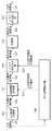
先ず、本実施形態に係る画像処理装置の機能構成例について、図1のブロック図を用いて説明する。画像処理装置には、画像変形処理を行う対象となる画像(入力画像)が入力されるのであるが、本実施形態ではこの入力画像が画素単位で入力されるものとして説明する。しかし、入力画像をどのようにして画像処理装置に入力するのかについては特に限定するものではない。 First, a functional configuration example of the image processing apparatus according to the present embodiment will be described with reference to the block diagram of FIG. An image (input image) to be subjected to image deformation processing is input to the image processing apparatus. In the present embodiment, description will be made assuming that this input image is input in units of pixels. However, there is no particular limitation on how the input image is input to the image processing apparatus.
画像処理装置に入力された入力画素の画素値(若しくは画像処理装置内のメモリから読み出された画素値)は、入力画素値121として入力画素記憶部101に格納されると共に、出力座標算出部106にも入力される。 The pixel value of the input pixel input to the image processing device (or the pixel value read from the memory in the image processing device) is stored in the input
画素補間処理部102は、入力画素に対応する出力画像上の画素の画素値を求める為に必要な画素(入力画素の周辺画素位置における画素)の画素値を入力周辺画素値122として入力画素記憶部101から読み出す。更に画素補間処理部102は、入力画素について出力座標算出部106が求めた各画素の画素位置(x座標値とy座標値)の小数部127を、出力座標算出部106から取得する。そして画素補間処理部102は、読み出した入力周辺画素値122と、取得した各画素の画素位置の小数部127と、を用いて補間処理を行い、入力画素に対応する出力画像上の画素の画素値を求める。 The pixel
補間処理には様々な補間技術を適用することができるが、例えば、バイリニア補間を行う場合、入力画素を含む2×2ピクセルからバイリニア補間を行い、補間された画素を出力する。また、バイキュービック補間を行う場合、入力画素を含む4×4ピクセルからバイキュービック補間を行い、補間された画素を出力する。 Various interpolation techniques can be applied to the interpolation processing. For example, when bilinear interpolation is performed, bilinear interpolation is performed from 2 × 2 pixels including input pixels, and the interpolated pixels are output. When bicubic interpolation is performed, bicubic interpolation is performed from 4 × 4 pixels including input pixels, and the interpolated pixels are output.
そして画素補間処理部102は、求めた画素値を入力補間画素値123としてメモリ書き込み部103に対して送出する。 Then, the pixel
メモリ書き込み部103は、出力座標算出部106から「入力画素に対応する出力画像上の画素の画素位置の整数部128」を受け取り、受け取った整数部128で表される画素位置に対応する記憶部104内のアドレスを特定する。そしてメモリ書き込み部103は、画素補間処理部102から受け取った入力補間画素値123を書き込み画素値124として、この特定したアドレスに格納する。 The
ランダムなアドレスに対する書き込みは低速である。しかし、連続するメモリアドレスへの書き込みが高速であるDRAMのようなメモリを記憶部104として用いる場合、メモリ書き込み部103内で入力補間画素値123のバッファリングを行う。そして、複数の入力補間画素値123をまとめて記憶部104に書き出すようにする。 Writing to random addresses is slow. However, in the case where a memory such as a DRAM that writes data at consecutive memory addresses at high speed is used as the
メモリ読み出し部105は、記憶部104に格納されている射影変換済みの画像の各画素の画素値を順次読み出し、出力画素値126として出力する。出力する順序については特に限定するものではないが、ラスタ順や縦方向を主走査とする方式や、タイルに分割してタイル毎に読み出しを行う方法などが考えられる。 The
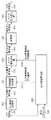
次に、出力座標算出部106のより詳細な機能構成例について、図2のブロック図を用いて説明する。入力画素座標生成部201は、入力画素値121を受け取ると、この入力画素の入力画像上(入力画像中)における画素位置を求める。例えば、入力画素値121の中にVSYNC、HSYNC信号が含まれているとする。この場合、入力画素座標生成部201はVSYNCを受けると、Y座標を0にリセットする。また入力画素座標生成部201は、HSYNCを受けると、X座標を0にリセットすると共に、前回のHSYNC信号を受けたときから画素値が入力されるとY座標を+1する。画素値が入力された時はX座標を+1する。そして入力画素座標生成部201は、このようにしてカウントしたX座標、Y座標をセットにして、入力画素座標値221として座標変換部202及び入力座標比較部205に対して送出する。なお、入力画素値121に入力画素の画素位置が含まれている場合には、この画素位置をそのまま入力画素座標値221として、座標変換部202及び入力座標比較部205に対して送出する。 Next, a more detailed functional configuration example of the output coordinate
座標変換部202は、射影変換用のマトリクスを用いて、入力画素座標値221に対する射影変換を行い、射影変換後の座標値を出力画素座標値222として求める。このマトリクスは、m11〜m33を成分とする3×3の行列で表される。この行列を用いて入力画素座標値221(xi,yi)に対する射影変換を行うことで、この入力画素座標値221(xi,yi)が写像される画素座標位置である出力画素座標値222(xo,yo)を求める。 The coordinate
この時、2×2ピクセルのバイリニア補間や4×4ピクセルのバイキュービックフィルタなどの偶数次のフィルタであればフィルタの中心座標が入力画素座標の中心から(+0.5,+0.5)ずれている。そのため、(xi+0.5,yi+0.5)に対する座標変換を行う。奇数次のフィルタであればフィルタの中心座標が(xi,yi)と同じであるため、(xi,yi)に対する座標変換を行う。以下に示す例は偶数次フィルタの時の出力画素座標値222(xo,yo)算出式である。 At this time, in the case of an even-order filter such as a 2 × 2 pixel bilinear interpolation or a 4 × 4 pixel bicubic filter, the center coordinate of the filter is shifted by (+0.5, +0.5) from the center of the input pixel coordinate. Yes. Therefore, coordinate conversion is performed on (xi + 0.5, yi + 0.5). In the case of an odd-order filter, the center coordinates of the filter are the same as (xi, yi), and therefore coordinate conversion is performed on (xi, yi). The following example is an expression for calculating the output pixel coordinate value 222 (xo, yo) for the even-order filter.
xo0=m11・(xi+0.5)+m12・(yi+0.5)+m13
yo0=m21・(xi+0.5)+m22・(yi+0.5)+m23
zo0=m31・(xi+0.5)+m32・(yi+0.5)+m33
xo=xo0/zo0
yo=yo0/zo0
そして座標変換部202は、このようにして求めた出力画素座標値222(xo、yo)を、後段の出力画素周辺座標生成部203に対して送出する。xo0 = m11 · (xi + 0.5) + m12 · (yi + 0.5) + m13
yo0 = m21 · (xi + 0.5) + m22 · (yi + 0.5) + m23
zo0 = m31 · (xi + 0.5) + m32 · (yi + 0.5) + m33
xo = xo0 / zo0
yo = yo0 / zo0
Then, the coordinate
出力画素周辺座標生成部203は、xoの小数部に0.5を加えた値の小数部が既定値以上であるか否か及び/又はyoの小数部に0.5を加えた値の小数部が既定値以上であるか否かの組み合わせに対して予め設定された複数の参照画素位置を取得する。 The output pixel peripheral coordinate
出力画素周辺座標生成部203のより詳細な機能構成例について、図3のブロック図を用いて説明する。出力座標量子化部206は、出力画素座標値222(xo、yo)に対して以下の式を適用することで、xoの整数部xoc、yoの整数部yocを算出する。 A more detailed functional configuration example of the output pixel peripheral coordinate
xoc=floor(xo+0.5)
yoc=floor(yo+0.5)
なお、floor(x)関数は、x以下の最大の整数を返す関数である。そして出力座標量子化部206は、画素位置(xoc、yoc)を、出力画素座標整数部231として、後段のサブ領域判定部207に対して出力する。xoc = floor (xo + 0.5)
yoc = floor (yo + 0.5)
The floor (x) function is a function that returns a maximum integer equal to or less than x. Then, the output coordinate
一方、出力座標量子化部206は、出力画素座標値222(xo、yo)に対して以下の式を適用することで、xoの小数部xof、yoの小数部yofを算出する。ここでは、後の判定を0≦xof<1,0≦yof<1で行うためにxo,yoからそれぞれの整数部を減じた後に0.5を加えているが、判定の都合によってxof,yofの算出式を変えることもできる。 On the other hand, the output coordinate
xof=xo−floor(xo+0.5)+0.5
yof=yo−floor(yo+0.5)+0.5
そして出力座標量子化部206は、このようにして求めたxof、yofを、出力画素座標小数部233として、後段のサブ領域判定部207に対して出力する。xof = xo-floor (xo + 0.5) +0.5
yof = yo−floor (yo + 0.5) +0.5
Then, the output coordinate
サブ領域判定部207は、xofが既定値以上であるか否か及び/又はyofが既定値以上であるか否かの組み合わせを特定する。ここで、サブ領域判定部207の動作について、図4を用いて説明する。図4のグラフにおいて横軸はxof、縦軸はyofを示す。 The
図4において領域301は、次のような条件を満たす領域である。先ず、画素位置(xoc、yoc)の右に隣接する画素位置(xoc+1、yoc)に対して上記の射影変換の逆変換を施すことで得られる画素位置が(p1、q1)であったとする。このとき、p1の整数部がxiと一致し、且つq1の整数部がyiと一致するような、xof、yofの範囲が領域301である。然るに、上記の式で求めたxof、yofによって表される位置(xof、yof)が領域301内に位置する場合、画素位置(xoc+1、yoc)に対して上記の射影変換の逆変換を施すことで得られるp1、q1のそれぞれの整数部はxi、yiと一致する。 In FIG. 4, an
以下に上記の射影変換の逆変換を行い(po,qo)から(pi,qi)を求める式と、偶数次フィルタで補間係数kを0≦k<1の範囲とする時の(pi,qi)から整数部(pic,qic)を算出する式を示す。なお、奇数次フィルタで補間係数kを−0.5≦k<0.5とするときはpi,qiに0.5を加えて整数部(pic,qic)を求める。 In the following, an inverse transformation of the above projective transformation is performed to obtain (pi, qi) from (po, qo), and (pi, qi when the interpolation coefficient k is in the range of 0 ≦ k <1 with an even-order filter. ) Represents an equation for calculating the integer part (pic, qic). When the interpolation coefficient k is set to −0.5 ≦ k <0.5 with an odd-order filter, 0.5 is added to pi and qi to obtain an integer part (pic, qic).
pi0=r11・po+r12・qo+r13
qi0=r21・po+r22・qo+r23
ri0=r31・po+r32・qo+r33
pi=pi0/ri0
qi=qi0/ri0
但し、(r11−r33)は(m11−m33)の逆行列である。射影変換に限定すれば、(r11−r33)は(m11−m33)の逆行列の定数倍であってもよい。pi0 = r11 · po + r12 · qo + r13
qi0 = r21 · po + r22 · qo + r23
ri0 = r31 · po + r32 · qo + r33
pi = pi0 / ri0
qi = qi0 / ri0
However, (r11-r33) is an inverse matrix of (m11-m33). If limited to projective transformation, (r11-r33) may be a constant multiple of the inverse matrix of (m11-m33).
pic=floor(pi)
qic=floor(qi)
同様に、画素位置(xoc、yoc)の下に隣接する画素位置(xoc、yoc+1)に対して上記の射影変換の逆変換を施すことで得られる画素位置が(p2、q2)であったとする。このとき、p2の整数部がxiと一致し、且つq2の整数部がyiと一致するような、xof、yofの範囲が領域302である。然るに、上記の式で求めたxof、yofによって表される位置(xof、yof)が領域302内に位置する場合、画素位置(xoc、yoc+1)に対して上記の射影変換の逆変換を施すことで得られるp2、q2のそれぞれの整数部はxi、yiと一致する。pic = floor (pi)
qic = floor (qi)
Similarly, it is assumed that the pixel position obtained by performing the inverse transformation of the above projective transformation on the pixel position (xoc, yoc + 1) adjacent below the pixel position (xoc, yoc) is (p2, q2). . At this time, the
同様に、画素位置(xoc、yoc)の左下に隣接する画素位置(xoc−1、yoc+1)に対して上記の射影変換の逆変換を施すことで得られる画素位置が(p3、q3)であったとする。このとき、p3の整数部がxiと一致し、且つq3の整数部がyiと一致するような、xof、yofの範囲が領域311である。然るに、上記の式で求めたxof、yofによって表される位置(xof、yof)が領域311内に位置する場合、画素位置(xoc−1、yoc+1)に上記の射影変換の逆変換を施すことで得られるp3、q3のそれぞれの整数部はxi、yiと一致する。 Similarly, the pixel position obtained by performing the inverse transformation of the above projective transformation on the pixel position (xoc-1, yoc + 1) adjacent to the lower left of the pixel position (xoc, yoc) is (p3, q3). Suppose. At this time, a
同様に、画素位置(xoc、yoc)の左に隣接する画素位置(xoc−1、yoc)に対して上記の射影変換の逆変換を施すことで得られる画素位置が(p4、q4)であったとする。このとき、p4の整数部がxiと一致し、且つq4の整数部がyiと一致するような、xof、yofの範囲が領域303である。然るに、上記の式で求めたxof、yofによって表される位置(xof、yof)が領域303内に位置する場合、画素位置(xoc−1、yoc)に対して上記の射影変換の逆変換を施すことで得られるp4、q4のそれぞれの整数部はxi、yiと一致する。 Similarly, the pixel position obtained by performing the inverse transformation of the above projective transformation on the pixel position (xoc-1, yoc) adjacent to the left of the pixel position (xoc, yoc) is (p4, q4). Suppose. At this time, the
同様に、画素位置(xoc、yoc)の上に隣接する画素位置(xoc、yoc−1)に対して上記の射影変換の逆変換を施すことで得られる画素位置が(p5、q5)であったとする。このとき、p5の整数部がxiと一致し、且つq5の整数部がyiと一致するような、xof、yofの範囲が領域304である。然るに、上記の式で求めたxof、yofによって表される位置(xof、yof)が領域304内に位置する場合、画素位置(xoc、yoc−1)に対して上記の射影変換の逆変換を施すことで得られるp5、q5のそれぞれの整数部はxi、yiと一致する。 Similarly, the pixel position obtained by performing the inverse transformation of the above projective transformation on the pixel position (xoc, yoc-1) adjacent to the pixel position (xoc, yoc) is (p5, q5). Suppose. At this time, the
同様に、画素位置(xoc、yoc)の右上に隣接する画素位置(xoc+1、yoc−1)に対して上記の射影変換の逆変換を施すことで得られる画素位置が(p6、q6)であったとする。このとき、p6の整数部がxiと一致し、且つq6の整数部がyiと一致するような、xof、yofの範囲が領域313である。然るに、上記の式で求めたxof、yofによって表される位置(xof、yof)が領域313内に位置する場合、画素位置(xoc+1、yoc−1)に上記の射影変換の逆変換を施すことで得られるp6、q6のそれぞれの整数部はxi、yiと一致する。 Similarly, the pixel position obtained by performing the inverse transformation of the above projective transformation on the pixel position (xoc + 1, yoc-1) adjacent to the upper right of the pixel position (xoc, yoc) is (p6, q6). Suppose. At this time, the range of xof and yof is such that the integer part of p6 matches xi and the integer part of q6 matches yi. However, when the position (xof, yof) represented by xof and yof obtained by the above formula is located in the
なお、図4では、画素位置(xoc−1、yoc−1)、(xoc+1、yoc+1)に対して上記の射影変換の逆変換を施すことで得られる画素位置は、x座標値の整数部=xi且つy座標値の整数部=yiという条件は満たしていないことになっている。 In FIG. 4, the pixel position obtained by performing the inverse transformation of the projective transformation on the pixel position (xoc−1, yoc−1), (xoc + 1, yoc + 1) is the integer part of the x coordinate value = The condition that x i and the integer part of the y coordinate value = y i is not satisfied.
然るに、図4を例に取り説明すると、サブ領域判定部207は、出力画素座標小数部233としてのxofが、0≦xof<0.5の範囲(サブ領域)に属しているのかそれとも0.5≦xof<1の範囲(サブ領域)に属しているのかを判定する。そしてサブ領域判定部207は、この判定の結果を、後段のサブ領域周辺座標出力部208に対して通知する。 However, taking FIG. 4 as an example, the
サブ領域周辺座標出力部208は、出力画素座標小数部233としてのxofが、0≦xof<0.5の範囲(サブ領域)に属している旨の通知を受けると、以下の画素位置を参照画素位置として決定する。 When the sub-region peripheral coordinate
(xoc 、yoc+1)
(xoc−1、yoc )
(xoc 、yoc−1)
(xoc−1、yoc+1)
一方、サブ領域周辺座標出力部208は、出力画素座標小数部233としてのxofが、0.5≦xof<1.0の範囲(サブ領域)に属している旨の通知を受けると、以下の画素位置を参照画素位置として決定する。(Xoc, yoc + 1)
(Xoc-1, yoc)
(Xoc, yoc-1)
(Xoc-1, yoc + 1)
On the other hand, when the sub-region peripheral coordinate
(xoc+1、yoc )
(xoc 、yoc+1)
(xoc 、yoc−1)
(xoc+1、yoc−1)
そしてサブ領域周辺座標出力部208は、上記のように、xofの属する範囲に応じて決まる参照画素位置と、画素位置(xoc、yoc)と、を出力画素周辺座標値223として出力する。(Xoc + 1, yoc)
(Xoc, yoc + 1)
(Xoc, yoc-1)
(Xoc + 1, yoc-1)
Then, as described above, the sub-region peripheral coordinate
なお、xofの属する範囲に応じて参照画素位置を決定する方法は特に限定するものではなく、様々な方法が考え得る。例えば、xofの属する範囲毎に、対応する参照画素位置を登録したテーブルを用いて、上記の求めたxocに対応する参照画素位置をこのテーブルから取得しても良い。 The method for determining the reference pixel position according to the range to which xof belongs is not particularly limited, and various methods can be considered. For example, for each range to which xof belongs, a reference pixel position corresponding to the obtained xoc may be obtained from this table using a table in which the corresponding reference pixel position is registered.
座標逆変換部204は、出力画素周辺座標値223としてのそれぞれの画素位置に対して、上記の射影変換の逆変換を施すことで、出力画素周辺座標値223としてのそれぞれの画素位置に対応する逆変換座標値を求める。ここで、xofの属する範囲に応じて決まる参照画素位置に対して、上記の射影変換の逆変換を施すことで得られる画素位置を(xi’、yi’)と表記する。また、画素位置(xoc、yoc)に対して上記の射影変換の逆変換を施す(計算する)ことで得られる画素位置を(xi”、yi”)と表記する。 The coordinate
そして座標逆変換部204は、この求めたそれぞれの逆変換座標値(xi’、yi’)、(xi”、yi”)を入力比較座標値224として、後段の入力座標比較部205に対して送出する。 Then, the coordinate
入力座標比較部205は、画素位置(xi”、yi”)、それぞれの(xi’、yi’)、のうち、x座標値の整数部及びy座標値の整数部がそれぞれxi、yiと同じである画素位置を特定する。そして入力座標比較部205は、特定した画素位置のx座標値の小数部及びy座標値の小数部を小数部127として画素補間処理部102に送出し、画素位置(xoc、yoc)128はメモリ書き込み部103に対して送出する。これにより画素補間処理部102は、上記の補間処理を行うことで、出力画像上の画素位置(xoc、yoc)における画素値を求めることができる。また、メモリ書き込み部103は、画素位置(xoc、yoc)に対応する記憶部104上のアドレスに、画素位置(xoc、yoc)における画素値を格納することができる。 The input coordinate
<変形例>
サブ領域判定部207の動作の変形例について、図5を用いて説明する。図5のグラフにおいて横軸はxof、縦軸はyofを示す。図5に示した参照番号が指し示す対象は、形状こそ違うものの、基本的な事項については図4と同じである。<Modification>
A modified example of the operation of the
図5において領域312は、次のような条件を満たす領域である。先ず、画素位置(xoc、yoc)の左上に隣接する画素位置(xoc−1、yoc−1)に対して上記の射影変換の逆変換を施すことで得られる画素位置が(p7、q7)であったとする。このとき、p7の整数部がxiと一致し、且つq7の整数部がyiと一致するような、xof、yofの範囲が領域312である。然るに、上記の式で求めたxof、yofによって表される位置(xof、yof)が領域312内に位置する場合、画素位置(xoc−1、yoc−1)に上記の射影変換の逆変換を施すことで得られるp7、q7のそれぞれの整数部はxi、yiと一致する。 In FIG. 5, a
同様に、画素位置(xoc、yoc)の右下に隣接する画素位置(xoc+1、yoc+1)に対して上記の射影変換の逆変換を施すことで得られる画素位置が(p8、q8)であったとする。このとき、p8の整数部がxiと一致し、且つq8の整数部がyiと一致するような、xof、yofの範囲が領域310である。然るに、上記の式で求めたxof、yofによって表される位置(xof、yof)が領域310内に位置する場合、画素位置(xoc+1、yoc+1)に上記の射影変換の逆変換を施すことで得られるp8、q8のそれぞれの整数部はxi、yiと一致する。 Similarly, when the pixel position (xoc + 1, yoc + 1) adjacent to the lower right of the pixel position (xoc, yoc) is subjected to the inverse transformation of the above projective transformation, the pixel position obtained is (p8, q8). To do. At this time, the
本変形例の場合、サブ領域周辺座標出力部208は、出力画素座標小数部233としてのxof、yofがそれぞれ、0.0≦xof<0.5、0.0≦yof<0.5の範囲に属している旨の通知を受けると、以下の画素位置を参照画素位置として決定する。 In the case of this modification, the sub-region peripheral coordinate
(xoc−1、yoc )
(xoc 、yoc−1)
(xoc−1、yoc−1)
また、サブ領域周辺座標出力部208は、出力画素座標小数部233としてのxof、yofがそれぞれ、0.5≦xof<1.0、0.0≦yof<0.5の範囲に属している旨の通知を受けると、以下の画素位置を参照画素位置として決定する。(Xoc-1, yoc)
(Xoc, yoc-1)
(Xoc-1, yoc-1)
Further, the sub-region peripheral coordinate
(xoc+1、yoc )
(xoc 、yoc−1)
(xoc+1、yoc−1)
また、サブ領域周辺座標出力部208は、出力画素座標小数部233としてのxof、yofがそれぞれ、0.0≦xof<0.5、0.5≦yof<1.0の範囲に属している旨の通知を受けると、以下の画素位置を参照画素位置として決定する。(Xoc + 1, yoc)
(Xoc, yoc-1)
(Xoc + 1, yoc-1)
In addition, the sub-region peripheral coordinate
(xoc−1、yoc )
(xoc 、yoc+1)
(xoc−1、yoc+1)
また、サブ領域周辺座標出力部208は、出力画素座標小数部233としてのxof、yofがそれぞれ、0.5≦xof<1.0、0.5≦yof<1.0の範囲に属している旨の通知を受けると、以下の画素位置を参照画素位置として決定する。(Xoc-1, yoc)
(Xoc, yoc + 1)
(Xoc-1, yoc + 1)
In the sub-region peripheral coordinate
(xoc 、yoc+1)
(xoc+1、yoc )
(xoc+1、yoc+1)
このように、xoの小数部に0.5を加えた値の小数部が既定値以上であるか否か及び/又はyoの小数部に0.5を加えた値の小数部が既定値以上であるか否かの組み合わせについては様々なものがあり、第1の実施形態や本変形例に限定するものではない。そして何れにせよ、それぞれの組み合わせには、予め設定された複数の参照画素位置が対応付けられているので、どのような組み合わせを想定しても、対応する参照画素位置群は一意に特定することができる。(Xoc, yoc + 1)
(Xoc + 1, yoc)
(Xoc + 1, yoc + 1)
Thus, whether or not the decimal part of the value obtained by adding 0.5 to the decimal part of xo is greater than or equal to the predetermined value and / or the decimal part of the value obtained by adding 0.5 to the decimal part of yo is greater than or equal to the predetermined value. There are various combinations of whether or not, and the combination is not limited to the first embodiment or the present modification. In any case, since each of the combinations is associated with a plurality of preset reference pixel positions, the corresponding reference pixel position group must be uniquely identified no matter what combination is assumed. Can do.
以上の説明により、本変形例を含めた本実施形態によれば、座標変換(座標逆変換)が必要な周辺画素の数を削減することができる。必要となる座標変換数を従来より少なくすることができるため、回路量を従来の書き込み時座標変換方式より少なくすることができる。 As described above, according to this embodiment including the present modification, the number of peripheral pixels that require coordinate transformation (coordinate inverse transformation) can be reduced. Since the required number of coordinate transformations can be reduced as compared with the prior art, the circuit amount can be reduced as compared with the conventional coordinate transformation method for writing.
また、必要なメモリ帯域のピーク値が小さいまま、ハードウェア実装したときの回路量を小さくすることができる、あるいはソフトウェア実装した時に処理性能が高い射影変換を行うことができる。 Further, while the required peak value of the memory bandwidth is small, the circuit amount when implemented with hardware can be reduced, or projective transformation with high processing performance can be performed when implemented with software.
[第2の実施形態]
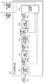
本実施形態に係る画像処理装置の機能構成例について、図6のブロック図を用いて説明する。図6において図1と同じ構成用件については同じ参照番号を付けており、その説明は省略する。本実施形態に係る画像処理装置は、図1に示した構成において、出力座標算出部106を出力座標算出部606に置き換えたものであり、この出力座標算出部606には、上記のマトリクスのデータである変形パラメータ129が入力される。然るに、出力座標算出部606以外の構成用件については第1の実施形態で説明したとおりであるため、以下ではこの出力座標算出部606について説明する。[Second Embodiment]
A functional configuration example of the image processing apparatus according to the present embodiment will be described with reference to the block diagram of FIG. In FIG. 6, the same components as those in FIG. The image processing apparatus according to the present embodiment is obtained by replacing the output coordinate
尚、以下の説明では、第1の実施形態でxo、yo、xoc、yocと表したものをそれぞれxot、yot、xotC、yotCと表記する。即ち、変数名が異なるだけで、指し示すものは同じであり、例えば、xoとxotとは指し示すものは同じである。 In the following description, what is expressed as xo, yo, xoc, yoc in the first embodiment is expressed as xot, yot, xotC, yotC, respectively. That is, only the variable names are different, and what is indicated is the same. For example, what is indicated by xo and xot is the same.
出力座標算出部606の機能構成例について、図7のブロック図を用いて説明する。図7において図2と同じ構成用件については同じ参照番号を付けており、その説明は省略する。 A functional configuration example of the output coordinate
座標変換部202は、第1の実施形態で説明したマトリクスのデータとしての変形パラメータ129を受けると、この変形パラメータ129を用いて第1の実施形態と同様にして、入力画素座標値221に対する射影変換を行う。そして座標変換部202は、この射影変換により得られた座標値を出力画素座標値222として、後段の出力画素周辺座標生成部203に対して送出する。 Upon receiving the
判定条件生成部703は、変形パラメータ129を受けると、この変形パラメータ129を用いて、参照画素位置を決定するための条件を生成する。そして判定条件生成部703は、この生成した条件を、判定条件704として出力画素周辺座標生成部203に対して供給する。判定条件生成部703の動作について、詳しくは後述する。 Upon receiving the
座標逆変換部204は、第1の実施形態で説明したマトリクスのデータとしての変形パラメータ129を受けると、この変形パラメータ129を用いて第1の実施形態と同様にして、出力画素周辺座標値223に対して射影変換の逆変換を行う。そして座標逆変換部204は、この逆変換により得られた逆変換座標値を入力画素周辺座標値701として、後段の座標出力部702に対して送出する。 When receiving the
座標出力部702は、入力画素周辺座標値701のx座標値の小数部及びy座標値の小数部を小数部127として画素補間処理部102に送出する。更に座標出力部702は、画素位置(xotC、yotC)を整数部128としてメモリ書き込み部103に送出する。 The coordinate
出力座標算出部606は、一例として画像変形を行わない場合は、1つの入力画素値121に対して、1つの整数部128及び1つの小数部127を出力する。具体的には、変形パラメータ129がm11〜m33からなる3x3の単位行列のときがこのような場合に当たる。また、その他の例として、画像変形が拡大部分を含むときは、1つの入力画素値121に対して、複数の整数部128及び小数部127が出力される場合がある。 The output coordinate
出力画素周辺座標生成部203は先ず、xoの小数部xotf、yoの小数部yotfを以下の式により求める。 First, the output pixel peripheral coordinate
xotf=xot−floor(xot+0.5)+0.5
yotf=yot−floor(yot+0.5)+0.5
そして出力画素周辺座標生成部203は、xotf及びyotfが、判定条件704を満たす場合には、この判定条件704に対応する複数の参照画素位置を取得する。そして出力画素周辺座標生成部203は、この取得した複数の参照画素位置と、画素位置(xotC、yotC)と、を出力画素周辺座標値223として出力する。ここで、出力画素周辺座標生成部203が出力画素周辺座標値223として出力する可能性があるものは、以下の9個の座標値である。xotf = xot−floor (xot + 0.5) +0.5
yotf = yot-floor (yot + 0.5) +0.5
The output pixel peripheral coordinate
(xotC−1,yotC−1)
(xotC+0,yotC−1)
(xotC+1,yotC−1)
(xotC−1,yotC+0)
(xotC+0,yotC+0)
(xotC+1,yotC+0)
(xotC−1,yotC+1)
(xotC+0,yotC+1)
(xotC+1,yotC+1)
図8のグラフにおいて横軸はxotf、縦軸はyotfを示す。図8において領域801は、次のような条件を満たす領域である。先ず、画素位置(xotC、yotC)の左上に隣接する画素位置(xotC−1、yotC−1)に対して上記の射影変換の逆変換を施すことで得られる画素位置が(p1、q1)であったとする。このとき、p1の整数部がxiと一致し、且つq1の整数部がyiと一致するような、xotf、yotfの範囲が領域801である。然るに、求めたxotf、yotfによって表される位置(xotf、yotf)が領域801内に位置する場合、画素位置(xotC−1、yotC−1)に上記の射影変換の逆変換を施して得られるp1、q1のそれぞれの整数部はxi、yiと一致する。これは、他の領域800,802〜805,808についても同様である。なお、それぞれの領域は重なる場合があり、図8では見易さの都合上、4つに分けて図示している。また、図8では、出力画素周辺座標生成部203が出力画素周辺座標値223として出力する可能性があるものは、以下の7個の座標値としている。(XotC-1, yotC-1)
(XotC + 0, yotC-1)
(XotC + 1, yotC-1)
(XotC-1, yotC + 0)
(XotC + 0, yotC + 0)
(XotC + 1, yotC + 0)
(XotC-1, yotC + 1)
(XotC + 0, yotC + 1)
(XotC + 1, yotC + 1)
In the graph of FIG. 8, the horizontal axis indicates xotf and the vertical axis indicates yotf. In FIG. 8, an
(xotC−1,yotC−1)
(xotC+0,yotC−1)
(xotC−1,yotC+0)
(xotC+0,yotC+0)
(xotC+1,yotC+0)
(xotC+0,yotC+1)
(xotC+1,yotC+1)
判定条件生成部703は、それぞれの領域800〜805,808を規定するパラメータを判定条件704として出力画素周辺座標生成部203に対して送出する。例えば、図8に示す如く、領域801は、直線A806と直線B807とxotf軸とyotf軸とによって囲まれている。直線A806と直線B807は以下のとおり表わすことができる。(XotC-1, yotC-1)
(XotC + 0, yotC-1)
(XotC-1, yotC + 0)
(XotC + 0, yotC + 0)
(XotC + 1, yotC + 0)
(XotC + 0, yotC + 1)
(XotC + 1, yotC + 1)
The determination
y=A1・x+A2 (直線A)
y=B1・x+B2 (直線B)
然るに、判定条件生成部703は、領域801を規定するパラメータとして、以下の条件を示すパラメータを生成する。y = A1 · x + A2 (Line A)
y = B1 · x + B2 (Line B)
However, the determination
0.0 ≦ xotf ≦ 1.0
0.0 ≦ yotf ≦ 1.0
yotf ≧ A1・xotf+A2 (直線A)
yotf ≧ B1・xotf+B2 (直線B)
また判定条件生成部703は、他の領域800,802〜805,808についてもこのような、それぞれの領域を規定するパラメータを生成する。そして判定条件生成部703は、それぞれの領域800〜805,808について生成したパラメータをまとめて判定条件704として出力画素周辺座標生成部203に対して送出する。0.0 ≦ xotf ≦ 1.0
0.0 ≦ yotf ≦ 1.0
yotf ≧ A1 · xotf + A2 (Line A)
yotf ≧ B1 · xotf + B2 (straight line B)
In addition, the determination
ここで、各領域を規定するためのパラメータを求めるための方法について説明する。各領域は、変形パラメータ129に依存しているため、各領域を規定するためのパラメータは、この変形パラメータ129を用いて生成されることになる。具体的には、各隣接画素座標値に対応する領域を囲む直線式の傾き係数と切片係数を求める。 Here, a method for obtaining parameters for defining each region will be described. Since each region depends on the
四角形が記されている図9(a)の入力画像(xi−yi平面)に対して変形パラメータ129を用いた画像変形処理を行うことで、変形した四角形が記されている図9(b)の出力画像(xot−yot平面)が得られたとする。図9(a)の四角形は頂点(入力端点)902〜905で構成されており、図9(b)の四角形は頂点(出力端点)906〜909で構成されている。 FIG. 9B shows a deformed quadrangle by performing image deformation processing using the
各領域の求め方について、図10を用いて説明する。図9(a)に示した入力端点902〜905のうち1つを入力端点505として選び、画像変形処理による入力端点505の変換後の端点を出力端点507として求める。出力端点507の画素位置を(Axo,Ayo)とすると、画素位置(floor(Axo)+0.5、floor(Ayo)+0.5)に出力中心点506を設定する。 A method of obtaining each area will be described with reference to FIG. One of the input end points 902 to 905 shown in FIG. 9A is selected as the
次に、画像変形処理の逆変換処理による出力中心点506の変換後の点を入力中心点508として求める。入力中心点508の画素位置を(Acxi,Acyi)とすると、以下の4つの画素位置にそれぞれ入力近傍点509〜512を設定する。 Next, a point after conversion of the output center point 506 by the inverse transformation process of the image deformation process is obtained as the
(Acxi−0.5,Acyi+0.5)
(Acxi+0.5,Acyi+0.5)
(Acxi+0.5,Acyi+0.5)
(Acxi−0.5,Acyi−0.5)
次に、画像変形処理による入力近傍点509〜512の変換後の点をそれぞれ出力近傍点514〜517として求める。そして出力近傍点514〜517で囲まれている領域のうち、0.0≦xot<1.0且つ0.0≦yot<1.0を満たす領域内を、判定領域518として求める。(Acxi-0.5, Acyi + 0.5)
(Acxi + 0.5, Acyi + 0.5)
(Acxi + 0.5, Acyi + 0.5)
(Acxi-0.5, Acyi-0.5)
Next, the converted points of the input neighboring points 509 to 512 by the image transformation process are obtained as
以上の判定領域518を求めるための処理を、入力端点902〜905のそれぞれについて行い、それぞれの領域について求めた判定領域518の和集合としての領域を、画素位置(xotC,yotC)に対する領域として出力する。同様の処理を、出力座標系501において出力中心点506を選択するとき、±1.0の8つの隣接画素座標に対して実行し、全ての領域を求めることができる。 The above processing for obtaining the determination area 518 is performed for each of the input end points 902 to 905, and an area as a union of the determination areas 518 obtained for each area is output as an area for the pixel position (xotC, yotC). To do. When the output center point 506 is selected in the output coordinate
出力画素周辺座標生成部203はこの判定条件704を受けると、判定条件704に含まれているそれぞれのパラメータを参照する。そして出力画素周辺座標生成部203は、上記の式で求めたxotf、yotfによって表される位置(xotf、yotf)が領域800〜805,808の何れに属しているのかを判定する。そして出力画素周辺座標生成部203は、上記の式で求めたxotf、yotfによって表される位置(xotf、yotf)が属していると判定した領域に対応する画素位置(参照画素位置)を出力する。 Upon receiving this determination condition 704, the output pixel peripheral coordinate
例えば、上記の式で求めたxotf、yotfによって表される位置(xotf、yotf)が、領域801内に位置している場合、画素位置(xotC−1、yotC−1)を参照画素位置として出力する。このようにして出力画素周辺座標生成部203は、上記の式で求めたxotf、yotfによって表される位置(xotf、yotf)が属していると判定した領域に対応する画素位置(参照画素位置)を出力する。 For example, when the position (xotf, yotf) represented by xotf, yotf obtained by the above formula is located in the
このように、本実施形態では、変形パラメータ129をもとに判定条件704を生成し、判定条件704にもとづき入力画素値121に対応する出力画素周辺座標値223を選択する。拡大率が2倍未満のとき、出力画素周辺座標値223の候補は9点だが、ここまでの説明のとおり、判定条件704を用いることで、出力画素周辺座標値223を4点以下に削減できる。この結果、座標逆変換部204による逆変換回数を削減できる。必要となる座標変換数を従来より少なくすることができるため、回路量を従来の書き込み時座標変換方式より少なくすることができる。また、必要なメモリ帯域のピーク値が小さいまま、ハードウェア実装したときの回路量が小さい、あるいはソフトウェア実装した時に処理性能が高い射影変形を行う画像処理技術を実現することができる。なお、本実施形態は、拡大率が任意の倍率の場合にも近傍点数を増やすことで同様に拡張可能である。 As described above, in this embodiment, the determination condition 704 is generated based on the
また、図1〜3,6,7に示した各部のうち、メモリとして機能するもの以外については、ソフトウェア(コンピュータプログラム)で実現させても良い。この場合、このメモリを有し、且つこのソフトウェアをインストールしたコンピュータは、このコンピュータが有するCPUがこのソフトウェアを実行することで、上記の画像処理装置として機能することになる。もちろん、図1〜3,6,7に示した全ての構成用件をハードウェアで実現させても良いし、一部をソフトウェアとして実現させても良い。 Moreover, you may implement | achieve by software (computer program) about things other than what functions as a memory among each part shown to FIGS. In this case, a computer having this memory and having this software installed functions as the above-described image processing apparatus when the CPU of this computer executes this software. Of course, all the configuration requirements shown in FIGS. 1 to 3, 6, and 7 may be realized by hardware, or a part may be realized as software.
(その他の実施例)
また、本発明は、以下の処理を実行することによっても実現される。即ち、上述した実施形態の機能を実現するソフトウェア(プログラム)を、ネットワーク又は各種記憶媒体を介してシステム或いは装置に供給し、そのシステム或いは装置のコンピュータ(またはCPUやMPU等)がプログラムを読み出して実行する処理である。(Other examples)
The present invention can also be realized by executing the following processing. That is, software (program) that realizes the functions of the above-described embodiments is supplied to a system or apparatus via a network or various storage media, and a computer (or CPU, MPU, or the like) of the system or apparatus reads the program. It is a process to be executed.
Claims (5)
Translated fromJapanese前記入力画像に対して前記画像変形処理を行うことで該入力画像中の画素位置(xi、yi)が写像される画素位置(xo、yo)を求める手段と、
xoの小数部に0.5を加えた値の小数部が既定値以上であるか否か及び/又はyoの小数部に0.5を加えた値の小数部が既定値以上であるか否かの組み合わせに対して予め設定された複数の参照画素位置を取得する取得手段と、
前記複数の参照画素位置のそれぞれに対して前記写像の逆写像を行うことで、画素位置(xi’、yi’)を求める手段と、
前記xoの整数部xoc及びyoの整数部yocで表される画素位置(xoc、yoc)に対して前記逆写像を行うことで、画素位置(xi”、yi”)を求める手段と、
前記画素位置(xi”、yi”)、前記複数の参照画素位置のそれぞれについて求めた前記画素位置(xi’、yi’)、のうち、x座標値の整数部及びy座標値の整数部がそれぞれxi、yiと同じである画素位置を特定する特定手段と、
前記特定手段が特定した画素位置のx座標値の小数部及びy座標値の小数部と、前記入力画像中の画素位置(xi、yi)の周辺画素位置における画素の画素値と、を用いた補間処理を行うことにより、前記出力画像上の画素位置(xoc、yoc)における画素値を求める算出手段と
を備えることを特徴とする画像処理装置。An image processing apparatus that generates an output image by performing an image transformation process on an input image,
Means for obtaining a pixel position (xo, yo) where the pixel position (xi, yi) in the input image is mapped by performing the image transformation process on the input image;
Whether or not the decimal part of the value obtained by adding 0.5 to the decimal part of xo is greater than or equal to the predetermined value and / or whether or not the decimal part of the value obtained by adding 0.5 to the decimal part of yo is greater than or equal to the predetermined value Acquisition means for acquiring a plurality of reference pixel positions set in advance for the combination;
Means for obtaining a pixel position (xi ′, yi ′) by performing an inverse mapping of the mapping for each of the plurality of reference pixel positions;
Means for obtaining a pixel position (xi ″, yi ″) by performing the inverse mapping on the pixel position (xoc, yoc) represented by the integer part xoc of yo and the integer part yoc of yo;
Of the pixel position (xi ″, yi ″) and the pixel position (xi ′, yi ′) obtained for each of the plurality of reference pixel positions, the integer part of the x coordinate value and the integer part of the y coordinate value are Specifying means for specifying pixel positions that are the same as xi and yi, respectively;
The decimal part of the x coordinate value and the decimal part of the y coordinate value of the pixel position specified by the specifying means, and the pixel value of the pixel at the peripheral pixel position of the pixel position (xi, yi) in the input image are used. An image processing apparatus comprising: a calculating unit that obtains a pixel value at a pixel position (xoc, yoc) on the output image by performing an interpolation process.
xoの小数部xofが0.0≦xof<0.5であれば、(xoc、yoc+1)、(xoc−1、yoc)、(xoc、yoc−1)、(xoc−1、yoc+1)を前記参照画素位置として取得し、
xoの小数部xofが0.5≦xof<1.0であれば、(xoc+1、yoc)、(xoc、yoc+1)、(xoc、yoc−1)、(xoc+1、yoc−1)を前記参照画素位置として取得する
ことを特徴とする請求項1に記載の画像処理装置。The acquisition means includes
If the decimal part xof of xo is 0.0 ≦ xof <0.5, (xoc, yoc + 1), (xoc-1, yoc), (xoc, yoc-1), (xoc-1, yoc + 1) As a reference pixel position,
If the decimal part xof of xo is 0.5 ≦ xof <1.0, (xoc + 1, yoc), (xoc, yoc + 1), (xoc, yoc-1), (xoc + 1, yoc-1) are used as the reference pixels. The image processing apparatus according to claim 1, wherein the image processing apparatus is acquired as a position.
xoの小数部xofが0.0≦xof<0.5且つyoの小数部yofが0.0≦yof<0.5であれば、(xoc−1、yoc)、(xoc、yoc−1)、(xoc−1、yoc−1)を前記参照画素位置として取得し、
xoの小数部xofが0.0≦xof<0.5且つyoの小数部yofが0.5≦yof<1.0であれば、(xoc−1、yoc)、(xoc、yoc+1)、(xoc−1、yoc+1)を前記参照画素位置として取得し、
xoの小数部xofが0.5≦xof<1.0且つyoの小数部yofが0.0≦yof<0.5であれば、(xoc+1、yoc)、(xoc、yoc−1)、(xoc+1、yoc−1)を前記参照画素位置として取得し、
xoの小数部xofが0.5≦xof<1.0且つyoの小数部yofが0.5≦yof<1.0であれば、(xoc、yoc+1)、(xoc+1、yoc)、(xoc+1、yoc+1)を前記参照画素位置として取得する
ことを特徴とする請求項1に記載の画像処理装置。The acquisition means includes
If the decimal part xof of xo is 0.0 ≦ xof <0.5 and the decimal part yof of yo is 0.0 ≦ yof <0.5, (xoc−1, yoc), (xoc, yoc−1) , (Xoc-1, yoc-1) as the reference pixel position,
If the decimal part xof of xo is 0.0 ≦ xof <0.5 and the decimal part yof of yo is 0.5 ≦ yof <1.0, (xoc−1, yoc), (xoc, yoc + 1), ( xoc-1, yoc + 1) as the reference pixel position,
If the decimal part xof of xo is 0.5 ≦ xof <1.0 and the decimal part yof of yo is 0.0 ≦ yof <0.5, (xoc + 1, yoc), (xoc, yoc−1), ( xoc + 1, yoc-1) as the reference pixel position,
If the decimal part xof of xo is 0.5 ≦ xof <1.0 and the decimal part yof of yo is 0.5 ≦ yof <1.0, (xoc, yoc + 1), (xoc + 1, yoc), (xoc + 1, The image processing apparatus according to claim 1, wherein yoc + 1) is acquired as the reference pixel position.
前記画像処理装置の写像手段が、前記入力画像に対して前記画像変形処理を行うことで該入力画像中の画素位置(xi、yi)が写像される画素位置(xo、yo)を求める工程と、
前記画像処理装置の取得手段が、xoの小数部に0.5を加えた値の小数部が既定値以上であるか否か及び/又はyoの小数部に0.5を加えた値の小数部が既定値以上であるか否かの組み合わせに対して予め設定された複数の参照画素位置を取得する取得工程と、
前記画像処理装置の逆写像手段が、前記複数の参照画素位置のそれぞれに対して前記写像の逆写像を行うことで、画素位置(xi’、yi’)を求める工程と、
前記画像処理装置の計算手段が、前記xoの整数部xoc及びyoの整数部yocで表される画素位置(xoc、yoc)に対して前記逆写像を行うことで、画素位置(xi”、yi”)を求める工程と、
前記画像処理装置の特定手段が、前記画素位置(xi”、yi”)、前記複数の参照画素位置のそれぞれについて求めた前記画素位置(xi’、yi’)、のうち、x座標値の整数部及びy座標値の整数部がそれぞれxi、yiと同じである画素位置を特定する特定工程と、
前記画像処理装置の算出手段が、前記特定工程で特定した画素位置のx座標値の小数部及びy座標値の小数部と、前記入力画像中の画素位置(xi、yi)の周辺画素位置における画素の画素値と、を用いた補間処理を行うことにより、前記出力画像上の画素位置(xoc、yoc)における画素値を求める算出工程と
を備えることを特徴とする画像処理方法。An image processing method performed by an image processing apparatus that generates an output image by performing an image transformation process on an input image,
A step in which mapping means of the image processing device obtains a pixel position (xo, yo) at which the pixel position (xi, yi) in the input image is mapped by performing the image transformation process on the input image; ,
Whether the decimal part of the value obtained by adding 0.5 to the decimal part of xo is greater than or equal to a predetermined value and / or the decimal value obtained by adding 0.5 to the decimal part of yo An acquisition step of acquiring a plurality of reference pixel positions set in advance for a combination of whether the part is equal to or greater than a predetermined value;
A step of obtaining a pixel position (xi ′, yi ′) by performing reverse mapping of the mapping with respect to each of the plurality of reference pixel positions;
The calculation means of the image processing device performs the inverse mapping on the pixel position (xoc, yoc) represented by the integer part xoc of yo and the integer part yoc of yo, so that the pixel position (xi ", yi) )), And
The specifying means of the image processing apparatus is an integer of x coordinate values among the pixel positions (xi ″, yi ″) and the pixel positions (xi ′, yi ′) obtained for each of the plurality of reference pixel positions. A specifying step for specifying a pixel position in which the integer part and the integer part of the y coordinate value are the same as xi and yi, respectively;
The calculation means of the image processing apparatus includes a decimal part of the x coordinate value and a decimal part of the y coordinate value of the pixel position specified in the specifying step, and a peripheral pixel position of the pixel position (xi, yi) in the input image. An image processing method comprising: a calculation step of obtaining a pixel value at a pixel position (xoc, yoc) on the output image by performing an interpolation process using a pixel value of the pixel.
Priority Applications (3)
| Application Number | Priority Date | Filing Date | Title |
|---|---|---|---|
| JP2011137737AJP5787637B2 (en) | 2011-06-21 | 2011-06-21 | Image processing apparatus and image processing method |
| US13/490,260US8509568B2 (en) | 2011-06-21 | 2012-06-06 | Image processing apparatus and image processing method |
| US13/957,375US20130315502A1 (en) | 2011-06-21 | 2013-08-01 | Image processing apparatus and image processing method |
Applications Claiming Priority (1)
| Application Number | Priority Date | Filing Date | Title |
|---|---|---|---|
| JP2011137737AJP5787637B2 (en) | 2011-06-21 | 2011-06-21 | Image processing apparatus and image processing method |
Publications (3)
| Publication Number | Publication Date |
|---|---|
| JP2013004031Atrue JP2013004031A (en) | 2013-01-07 |
| JP2013004031A5 JP2013004031A5 (en) | 2014-07-31 |
| JP5787637B2 JP5787637B2 (en) | 2015-09-30 |
Family
ID=47361919
Family Applications (1)
| Application Number | Title | Priority Date | Filing Date |
|---|---|---|---|
| JP2011137737AExpired - Fee RelatedJP5787637B2 (en) | 2011-06-21 | 2011-06-21 | Image processing apparatus and image processing method |
Country Status (2)
| Country | Link |
|---|---|
| US (2) | US8509568B2 (en) |
| JP (1) | JP5787637B2 (en) |
Cited By (2)
| Publication number | Priority date | Publication date | Assignee | Title |
|---|---|---|---|---|
| JP2015138403A (en)* | 2014-01-22 | 2015-07-30 | キヤノン株式会社 | Image processor, image processing method and program |
| WO2018168506A1 (en)* | 2017-03-13 | 2018-09-20 | Necソリューションイノベータ株式会社 | Image conversion assist device, image conversion device, image conversion assist method, and computer readable recording medium |
Families Citing this family (1)
| Publication number | Priority date | Publication date | Assignee | Title |
|---|---|---|---|---|
| CN116309058B (en)* | 2023-03-15 | 2024-04-19 | 长沙观谱红外科技有限公司 | Human body infrared image amplification processing method |
Citations (4)
| Publication number | Priority date | Publication date | Assignee | Title |
|---|---|---|---|---|
| JPS6256073A (en)* | 1985-09-04 | 1987-03-11 | Canon Inc | Image processing method |
| JPH06149993A (en)* | 1992-11-09 | 1994-05-31 | Matsushita Electric Ind Co Ltd | Image conversion processing method and image conversion processing apparatus |
| US5870105A (en)* | 1996-05-31 | 1999-02-09 | Hewlett-Packard Company | System and method for local storage of image data during object to image mapping |
| JP2001266138A (en)* | 2000-03-23 | 2001-09-28 | Seiko Epson Corp | Image conversion processing device, image conversion processing method, and information recording medium |
Family Cites Families (15)
| Publication number | Priority date | Publication date | Assignee | Title |
|---|---|---|---|---|
| US5204944A (en)* | 1989-07-28 | 1993-04-20 | The Trustees Of Columbia University In The City Of New York | Separable image warping methods and systems using spatial lookup tables |
| US5768438A (en)* | 1994-10-19 | 1998-06-16 | Matsushita Electric Industrial Co., Ltd. | Image encoding/decoding device |
| US6317158B1 (en)* | 1998-10-23 | 2001-11-13 | Avid Technology, Inc. | Method and apparatus for positioning an input image into interlaced video |
| JP3543928B2 (en)* | 1998-10-29 | 2004-07-21 | 三菱電機株式会社 | Pixel number converter |
| US7729563B2 (en)* | 2002-08-28 | 2010-06-01 | Fujifilm Corporation | Method and device for video image processing, calculating the similarity between video frames, and acquiring a synthesized frame by synthesizing a plurality of contiguous sampled frames |
| KR20050050614A (en)* | 2002-10-08 | 2005-05-31 | 소니 가부시끼 가이샤 | Image conversion device, image conversion method, and image projection device |
| JP4124096B2 (en) | 2003-10-29 | 2008-07-23 | 株式会社ニコン | Image processing method, image processing apparatus, and program |
| KR100595254B1 (en)* | 2004-01-17 | 2006-07-03 | 엘지전자 주식회사 | Coordinate transformation device and method |
| US7324706B2 (en)* | 2004-09-09 | 2008-01-29 | Silicon Optix Inc. | System and method for representing a general two dimensional spatial transformation |
| US20060204125A1 (en)* | 2005-03-09 | 2006-09-14 | Kempf Jeffrey M | Multi-dimensional keystone correction image projection system and method |
| US8379066B2 (en)* | 2007-06-27 | 2013-02-19 | Christie Digital Systems Usa, Inc. | Method and apparatus for scaling an image to produce a scaled image |
| JP5408906B2 (en) | 2008-05-28 | 2014-02-05 | キヤノン株式会社 | Image processing device |
| JP2010081024A (en)* | 2008-09-24 | 2010-04-08 | Oki Semiconductor Co Ltd | Device for interpolating image |
| JP5585885B2 (en)* | 2011-03-18 | 2014-09-10 | 株式会社リコー | Image processing apparatus and image processing method |
| JP5997480B2 (en)* | 2012-03-30 | 2016-09-28 | キヤノン株式会社 | Image processing apparatus, image processing method, and program |
- 2011
- 2011-06-21JPJP2011137737Apatent/JP5787637B2/ennot_activeExpired - Fee Related
- 2012
- 2012-06-06USUS13/490,260patent/US8509568B2/ennot_activeExpired - Fee Related
- 2013
- 2013-08-01USUS13/957,375patent/US20130315502A1/ennot_activeAbandoned
Patent Citations (4)
| Publication number | Priority date | Publication date | Assignee | Title |
|---|---|---|---|---|
| JPS6256073A (en)* | 1985-09-04 | 1987-03-11 | Canon Inc | Image processing method |
| JPH06149993A (en)* | 1992-11-09 | 1994-05-31 | Matsushita Electric Ind Co Ltd | Image conversion processing method and image conversion processing apparatus |
| US5870105A (en)* | 1996-05-31 | 1999-02-09 | Hewlett-Packard Company | System and method for local storage of image data during object to image mapping |
| JP2001266138A (en)* | 2000-03-23 | 2001-09-28 | Seiko Epson Corp | Image conversion processing device, image conversion processing method, and information recording medium |
Cited By (2)
| Publication number | Priority date | Publication date | Assignee | Title |
|---|---|---|---|---|
| JP2015138403A (en)* | 2014-01-22 | 2015-07-30 | キヤノン株式会社 | Image processor, image processing method and program |
| WO2018168506A1 (en)* | 2017-03-13 | 2018-09-20 | Necソリューションイノベータ株式会社 | Image conversion assist device, image conversion device, image conversion assist method, and computer readable recording medium |
Also Published As
| Publication number | Publication date |
|---|---|
| US20120328214A1 (en) | 2012-12-27 |
| US8509568B2 (en) | 2013-08-13 |
| US20130315502A1 (en) | 2013-11-28 |
| JP5787637B2 (en) | 2015-09-30 |
Similar Documents
| Publication | Publication Date | Title |
|---|---|---|
| JP5914045B2 (en) | Image processing apparatus, image processing method, and program | |
| US8928782B2 (en) | Image processing device and image capture device | |
| JP2019120749A (en) | Display controller, image projection system, control method and program | |
| US9332238B2 (en) | Image processing apparatus and image processing method | |
| JP5787637B2 (en) | Image processing apparatus and image processing method | |
| JP2002014611A (en) | Video projecting method to planetarium or spherical screen and device therefor | |
| JP2017191572A (en) | Image processing apparatus and method, and program | |
| JP2012238171A (en) | Image processing device, image processing method and program | |
| JP2019106589A (en) | Projector, geometric distortion correction method, and program | |
| JP6487671B2 (en) | Image processing apparatus and image processing method. And programs | |
| US11893706B2 (en) | Image correction device | |
| JP6278716B2 (en) | Image processing apparatus, image processing method, and program | |
| JP6632434B2 (en) | Image processing apparatus, image processing method, and program | |
| JP2017208782A (en) | Video processing apparatus, video processing method, and program | |
| JP6972089B2 (en) | Image processing equipment, image processing methods, and programs | |
| JP2015227913A (en) | Image processing apparatus, display apparatus, image processing method, and program | |
| JP5387276B2 (en) | Image processing apparatus and image processing method | |
| JP6285657B2 (en) | Image processing apparatus, image processing method, and program | |
| JP2012019315A (en) | Image processor and image processing method | |
| KR102781162B1 (en) | Electronic apparatus for real-time 2-dimensional image transformation of digital images and transformation method therefor | |
| JP2013257665A (en) | Movie processing apparatus and control method therefor | |
| JP2011070571A (en) | Apparatus, method and program for processing image | |
| JP2015154209A (en) | Image processing apparatus, image processing method, and program | |
| JP2017120530A (en) | Image processing apparatus and image processing method | |
| JP2004227470A (en) | Image conversion method and image-converting computer program |
Legal Events
| Date | Code | Title | Description |
|---|---|---|---|
| A521 | Request for written amendment filed | Free format text:JAPANESE INTERMEDIATE CODE: A523 Effective date:20140616 | |
| A621 | Written request for application examination | Free format text:JAPANESE INTERMEDIATE CODE: A621 Effective date:20140616 | |
| A977 | Report on retrieval | Free format text:JAPANESE INTERMEDIATE CODE: A971007 Effective date:20150212 | |
| A131 | Notification of reasons for refusal | Free format text:JAPANESE INTERMEDIATE CODE: A131 Effective date:20150306 | |
| A521 | Request for written amendment filed | Free format text:JAPANESE INTERMEDIATE CODE: A523 Effective date:20150507 | |
| TRDD | Decision of grant or rejection written | ||
| A01 | Written decision to grant a patent or to grant a registration (utility model) | Free format text:JAPANESE INTERMEDIATE CODE: A01 Effective date:20150629 | |
| A61 | First payment of annual fees (during grant procedure) | Free format text:JAPANESE INTERMEDIATE CODE: A61 Effective date:20150728 | |
| R151 | Written notification of patent or utility model registration | Ref document number:5787637 Country of ref document:JP Free format text:JAPANESE INTERMEDIATE CODE: R151 | |
| LAPS | Cancellation because of no payment of annual fees |