JP2013003691A - Computing system and disk sharing method in computing system - Google Patents
Computing system and disk sharing method in computing systemDownload PDFInfo
- Publication number
- JP2013003691A JP2013003691AJP2011131806AJP2011131806AJP2013003691AJP 2013003691 AJP2013003691 AJP 2013003691AJP 2011131806 AJP2011131806 AJP 2011131806AJP 2011131806 AJP2011131806 AJP 2011131806AJP 2013003691 AJP2013003691 AJP 2013003691A
- Authority
- JP
- Japan
- Prior art keywords
- disk
- lpar
- storage controller
- internal
- virtual
- Prior art date
- Legal status (The legal status is an assumption and is not a legal conclusion. Google has not performed a legal analysis and makes no representation as to the accuracy of the status listed.)
- Granted
Links
Images


Classifications
- G—PHYSICS
- G06—COMPUTING OR CALCULATING; COUNTING
- G06F—ELECTRIC DIGITAL DATA PROCESSING
- G06F3/00—Input arrangements for transferring data to be processed into a form capable of being handled by the computer; Output arrangements for transferring data from processing unit to output unit, e.g. interface arrangements
- G06F3/06—Digital input from, or digital output to, record carriers, e.g. RAID, emulated record carriers or networked record carriers
- G06F3/0601—Interfaces specially adapted for storage systems
- G06F3/0602—Interfaces specially adapted for storage systems specifically adapted to achieve a particular effect
- G06F3/0604—Improving or facilitating administration, e.g. storage management
- G—PHYSICS
- G06—COMPUTING OR CALCULATING; COUNTING
- G06F—ELECTRIC DIGITAL DATA PROCESSING
- G06F3/00—Input arrangements for transferring data to be processed into a form capable of being handled by the computer; Output arrangements for transferring data from processing unit to output unit, e.g. interface arrangements
- G06F3/06—Digital input from, or digital output to, record carriers, e.g. RAID, emulated record carriers or networked record carriers
- G06F3/0601—Interfaces specially adapted for storage systems
- G06F3/0628—Interfaces specially adapted for storage systems making use of a particular technique
- G06F3/0629—Configuration or reconfiguration of storage systems
- G06F3/0631—Configuration or reconfiguration of storage systems by allocating resources to storage systems
- G—PHYSICS
- G06—COMPUTING OR CALCULATING; COUNTING
- G06F—ELECTRIC DIGITAL DATA PROCESSING
- G06F3/00—Input arrangements for transferring data to be processed into a form capable of being handled by the computer; Output arrangements for transferring data from processing unit to output unit, e.g. interface arrangements
- G06F3/06—Digital input from, or digital output to, record carriers, e.g. RAID, emulated record carriers or networked record carriers
- G06F3/0601—Interfaces specially adapted for storage systems
- G06F3/0628—Interfaces specially adapted for storage systems making use of a particular technique
- G06F3/0662—Virtualisation aspects
- G06F3/0664—Virtualisation aspects at device level, e.g. emulation of a storage device or system
- G—PHYSICS
- G06—COMPUTING OR CALCULATING; COUNTING
- G06F—ELECTRIC DIGITAL DATA PROCESSING
- G06F3/00—Input arrangements for transferring data to be processed into a form capable of being handled by the computer; Output arrangements for transferring data from processing unit to output unit, e.g. interface arrangements
- G06F3/06—Digital input from, or digital output to, record carriers, e.g. RAID, emulated record carriers or networked record carriers
- G06F3/0601—Interfaces specially adapted for storage systems
- G06F3/0668—Interfaces specially adapted for storage systems adopting a particular infrastructure
- G06F3/067—Distributed or networked storage systems, e.g. storage area networks [SAN], network attached storage [NAS]
- G—PHYSICS
- G06—COMPUTING OR CALCULATING; COUNTING
- G06F—ELECTRIC DIGITAL DATA PROCESSING
- G06F9/00—Arrangements for program control, e.g. control units
- G06F9/06—Arrangements for program control, e.g. control units using stored programs, i.e. using an internal store of processing equipment to receive or retain programs
- G06F9/46—Multiprogramming arrangements
- G06F9/50—Allocation of resources, e.g. of the central processing unit [CPU]
- G06F9/5061—Partitioning or combining of resources
- G06F9/5077—Logical partitioning of resources; Management or configuration of virtualized resources
Landscapes
- Engineering & Computer Science (AREA)
- Theoretical Computer Science (AREA)
- Physics & Mathematics (AREA)
- General Engineering & Computer Science (AREA)
- General Physics & Mathematics (AREA)
- Human Computer Interaction (AREA)
- Software Systems (AREA)
- Information Retrieval, Db Structures And Fs Structures Therefor (AREA)
Abstract
Description
Translated fromJapanese本発明は、複数の物理サーバ間でのデータを共有する方法およびシステムに関する。 The present invention relates to a method and system for sharing data among a plurality of physical servers.
企業情報システムにおいては一台のストレージ装置に多数の物理サーバが接続し、ストレージ装置内のデータを共有する共有ストレージ構成が一般的である。このような構成をとることで、データの一元管理ができるほか、サーバ装置の可用性を向上させるホットスタンバイ機能やバックアップ機能などを有効に使うことができる。また、サーバ仮想化環境において、仮想サーバを現在稼働中の物理サーバから異なる物理サーバへ移行するマイグレーション機能などは移行元と移行先のサーバがお互いにデータを参照できる共有ストレージ構成の採用が必須要件である。共有ストレージを構築するには、異なるサーバ間でファイルを共有するNAS(Network Attached Storage)の技術や、FC(Fibre Channel)やiSCSI(Internet Small Computer System Interface)などのプロトコルを使ってブロックストレージを共有するSAN(Storage Area Network)の技術を使う。 In an enterprise information system, a common storage configuration in which a large number of physical servers are connected to a single storage apparatus and data in the storage apparatus is shared is common. By adopting such a configuration, it is possible to centrally manage data and to effectively use a hot standby function and a backup function that improve the availability of the server device. Also, in a server virtualization environment, a migration function that migrates a virtual server from a currently running physical server to a different physical server must employ a shared storage configuration that allows the source and destination servers to refer to each other's data. It is. To build shared storage, share block storage using NAS (Network Attached Storage) technology that shares files between different servers, FC (Fibre Channel), iSCSI (Internet Small Computer System Interface), and other protocols. The technology of SAN (Storage Area Network) is used.
一方で、共有ストレージを必要としない企業情報システムも存在する。例として、Hadoopに代表される大量データの分散処理システムや、ロードバランサを利用したWebサーバの負荷分散システムなどが挙げられる。これらのシステムは異なるサーバの間でデータを共有する必要がないため、データの保存に共有ストレージではなくサーバの内蔵ディスクを使用することが多い。 On the other hand, there are enterprise information systems that do not require shared storage. Examples include a distributed processing system for a large amount of data represented by Hadoop, a load distribution system for a Web server using a load balancer, and the like. Since these systems do not need to share data between different servers, the server's built-in disk is often used instead of shared storage for data storage.
現在の企業情報システムは、このようにデータの保存場所が異なる2種のシステムが同一の環境内で混在している。データの保存場所として内蔵ディスクと共有ストレージのどちらを使うかは、企業情報システムの要件に応じて決められる。一般に、共有ストレージよりも内蔵ディスクの方が安価であるため、コスト削減を求める企業には内蔵ディスクを積極的に採用したい要求がある。 In the current corporate information system, two types of systems having different data storage locations are mixed in the same environment. Whether to use the internal disk or shared storage as the data storage location depends on the requirements of the enterprise information system. In general, internal disks are cheaper than shared storage, so companies that want to reduce costs have a desire to actively adopt internal disks.
企業がコスト削減を目的に内蔵ディスクの採用を進めるにあたり、ディスク共有の問題がある。システム内の第一のサーバと第二のサーバが共に内蔵ディスクを備え、それぞれ第一のプログラムと第二のプログラムを動作させている場合を例にとり説明する。第一のサーバ上で動作する第一のプログラムは、第一のサーバが備える第一のディスクアダプタを介して第一の内蔵ディスクに対して入出力処理を行える。しかし、第二のサーバが備えた第二の内蔵ディスクに対しては、第一のディスクアダプタと第二の内蔵ディスクが接続されていないため、入出力処理を行えない。この場合の入出力処理とは、内蔵ディスクに保存されたデータの読み書きである。このことは、異なるサーバ上に存在する第一のプログラムと第二のプログラムとの間でデータの共有ができないことを意味する。 There is a problem of disk sharing as companies adopt internal disks to reduce costs. A case will be described as an example where both the first server and the second server in the system are provided with built-in disks, and the first program and the second program are operated, respectively. The first program running on the first server can perform input / output processing for the first internal disk via the first disk adapter provided in the first server. However, since the first disk adapter and the second built-in disk are not connected to the second built-in disk provided in the second server, input / output processing cannot be performed. The input / output processing in this case is reading / writing of data stored in the internal disk. This means that data cannot be shared between the first program and the second program that exist on different servers.
これにより、コスト削減のために内蔵ディスクを採用する要求があっても、バックアップやマイグレーションなどの利便性が高い機能はディスクの共有を必要とするため、それらの機能を使う場合には高価な共有ストレージを採用しなければならない。 As a result, even if there is a request to use an internal disk for cost reduction, highly convenient functions such as backup and migration require disk sharing, so expensive sharing is required when using these functions. Storage must be adopted.
つまり、従来技術においては、複数の物理サーバ間で内蔵ディスクを共有できない点が課題である。 That is, the problem with the prior art is that the internal disk cannot be shared among a plurality of physical servers.
特許文献1では、移行元と移行先の物理サーバが内蔵ディスクを持ち、データの共有を行っていない環境において仮想サーバのライブマイグレーションを実現する発明が開示されている。特許文献1の発明は、移行元と移行先の物理サーバの双方がアクセスできる小容量の共有ストレージを配置し、そこにデータの中身でなく差分スナップショットを配置することで疑似的にデータの共有を行い、内蔵ディスクを使いながらもマイグレーション機能を実現している。ただし、この発明は小容量のストレージを用いる。そのためデータの共有を行う二つのサーバとは別にストレージ装置を設置する必要があり、コストがかかる点は従来技術と同様である。
本発明のディスク共有システムは、複数の物理サーバと、前記複数の物理サーバに接続された管理サーバを含むシステムである。第一の物理サーバは、内蔵ディスクと、第一の仮想化機構と、前記第一の仮想化機構により論理分割された第一のLPAR及び第一のストレージコントローラLPARとを備える。第二の物理サーバは、第二の仮想化機構と、前記第二の仮想化機構により論理分割された第二のLPAR及び第二のストレージコントローラLPARと、前記第二のストレージコントローラLPARにより前記第一の物理サーバの前記内蔵ディスクを模擬して生成された仮想ディスクとを備える。また、前記第一のストレージコントローラLPARと、前記第二のストレージコントローラLPARとは相互に通信する。このシステムにおいて、前記第二のストレージコントローラLPARは、前記第二のLPARが発行した前記仮想ディスクのディスク入出力命令を、前記第一のストレージコントローラLPARに転送する。前記第一のストレージコントローラLPARは、前記ディスク入出力命令を参照して、前記ディスク入出力命令に含まれる内蔵ディスクの識別子を取得し、取得した識別子に対応する内蔵ディスクに対して、前記ディスク入出力命令を実行する。 The disk sharing system of the present invention is a system including a plurality of physical servers and a management server connected to the plurality of physical servers. The first physical server includes an internal disk, a first virtualization mechanism, and a first LPAR and a first storage controller LPAR that are logically partitioned by the first virtualization mechanism. The second physical server includes a second virtualization mechanism, a second LPAR and a second storage controller LPAR logically partitioned by the second virtualization mechanism, and the second storage controller LPAR. A virtual disk generated by simulating the internal disk of one physical server. The first storage controller LPAR and the second storage controller LPAR communicate with each other. In this system, the second storage controller LPAR transfers a disk input / output command of the virtual disk issued by the second LPAR to the first storage controller LPAR. The first storage controller LPAR refers to the disk input / output command, acquires an identifier of the internal disk included in the disk input / output command, and applies the disk input to the internal disk corresponding to the acquired identifier. Execute the output instruction.
本発明により、内蔵ディスクを備えた複数の物理サーバにおいて、物理サーバ上で動作するプログラムが異なる物理サーバの内蔵ディスクを共有できる。 According to the present invention, a plurality of physical servers provided with a built-in disk can share a built-in disk of a physical server with different programs running on the physical server.
内蔵ディスクを備えた物理サーバを仮想化機構により論理分割し、仮想化機構の上でLPAR(Logical Partition)を稼働し、LPARが内蔵ディスクに対して入出力処理を行う構成において、異なる物理サーバの内蔵ディスクを共有する処理を実行する専用のLPAR(ストレージコントローラLPAR)を前記LPARと同じ仮想化機構の上で稼働させる構成をとる。前記の構成をとる複数の物理サーバと、物理サーバを管理する管理サーバが存在するシステムにおいて、第一の物理サーバ上で稼働する第一のストレージコントローラLPARと、第二の物理サーバ上で稼働する第二のストレージコントローラLPARとが、ネットワークを介して互いに通信を行う。 In a configuration in which a physical server provided with an internal disk is logically divided by a virtualization mechanism, LPAR (Logical Partition) is operated on the virtualization mechanism, and LPAR performs input / output processing for the internal disk. A configuration is adopted in which a dedicated LPAR (storage controller LPAR) that executes processing for sharing an internal disk is operated on the same virtualization mechanism as the LPAR. In a system including a plurality of physical servers configured as described above and a management server that manages the physical servers, the system operates on the first storage controller LPAR that operates on the first physical server and the second physical server. The second storage controller LPAR communicates with each other via a network.
本発明は、第一の物理サーバ上で稼働する第一のLPARが内蔵ディスクに対して入出力処理を行い、第二の物理サーバ上で稼働する第二のLPARが内蔵ディスクを共有する要求がある場合に、第一のストレージコントローラLPARと第二のストレージコントローラLPARが管理サーバ内の情報を読み書きすることによって、それぞれのストレージコントローラLPARが管理するLPARとディスクの情報を共有する。そして、第二のストレージコントローラLPARが、第二のLPARが発行するディスク入出力命令を第一のストレージコントローラLPARに転送することで、第二のLPARが内蔵ディスクに保存されたデータを読み書きし、これにより内蔵ディスクの共有を行う。以下、本発明を適用したシステムの実施例について、図面を参照しながら説明する。実施例1では、共有対象となる内蔵ディスクと、内蔵ディスクを利用する第一のLPARと、内蔵ディスクを管理する第一のストレージコントローラLPARとを含む第一のサーバと、第二のLPARと第二のストレージコントローラLPARとを含む第二のサーバと、管理サーバとの連携によって、第二のサーバ上で稼働する第二のLPARが、第一のサーバが備える内蔵ディスクを共有するシステムの構成、および、方法を示す。 In the present invention, there is a request that the first LPAR operating on the first physical server performs input / output processing with respect to the internal disk, and the second LPAR operating on the second physical server shares the internal disk. In some cases, the first storage controller LPAR and the second storage controller LPAR read and write information in the management server, thereby sharing the disk information with the LPAR managed by each storage controller LPAR. Then, the second storage controller LPAR transfers the disk input / output command issued by the second LPAR to the first storage controller LPAR so that the second LPAR reads / writes data stored in the internal disk, As a result, the internal disk is shared. Embodiments of a system to which the present invention is applied will be described below with reference to the drawings. In the first embodiment, a first server including a built-in disk to be shared, a first LPAR that uses the built-in disk, a first storage controller LPAR that manages the built-in disk, a second LPAR, A configuration of a system in which a second LPAR operating on the second server shares a built-in disk included in the first server by cooperation between the second server including the second storage controller LPAR and the management server; And a method.
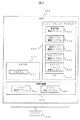
図1は、ディスク共有システムの構成の一例を示す図である。 FIG. 1 is a diagram illustrating an example of the configuration of a disk sharing system.
ディスク共有システムは、管理サーバ100と、第一のサーバ110と、第二のサーバ120と、ネットワーク130とにより構成される。管理サーバ100、第一のサーバ110、第二のサーバ120は物理サーバであり、ネットワーク130によって相互に接続される。 The disk sharing system includes a
第一のサーバ110では仮想化機構111が稼働し、その上で第一のLPAR112と第一のストレージコントローラLPAR113が稼働している。また、第一のサーバ110は、物理ディスクアダプタ116と、物理ディスクアダプタ116に接続された内蔵ディスク117とを備える。 In the
第一のLPAR112は仮想ディスクアダプタ114と物理ディスクアダプタ116を介して内蔵ディスク117に接続する。第一のLPAR112は仮想ディスクアダプタ114に対してディスク入出力命令を発行することで、内蔵ディスク117に保存されたデータを読み書きする。 The
また、第一のストレージコントローラLPAR113は、仮想ディスクアダプタ115と物理ディスクアダプタ116に接続し、第一のLPAR112と同様に内蔵ディスク117を読み書きする。 Further, the first
ここで二つの仮想ディスクアダプタ114、115は、仮想化機構111が作成し、第一のLPAR112と第一のストレージコントローラLPAR113とにそれぞれ割り当てたものである。 Here, the two
第二のサーバ120では第一のサーバ110と同様に仮想化機構121が稼働し、その上で第二のLPAR122と第二のストレージコントローラLPAR123が稼働している。なお、第二のサーバ120も第一のサーバ110と同様に物理ディスクアダプタや内蔵ディスクを備えていてもよい。 In the
第二のサーバ120上の第二のLPAR122は、仮想ディスクアダプタ124を介し、第二のストレージコントローラLPAR123上の仮想ディスク125と接続している。ここで仮想ディスクアダプタ124は、仮想化機構121が作成し、第二のLPAR122に割り当てたものである。 The
仮想ディスク125は、第二のストレージコントローラLPAR123のソフトウェアにより作成されたディスクであり、物理的には存在しない仮想的なディスクである。仮想ディスク125は、第一のサーバ111上の内蔵ディスク117に対応して作成される。第二のLPAR122が仮想ディスクアダプタ124を介し仮想ディスク125に対してディスク入出力命令を発行すると、前記ディスク入出力命令は仮想化機構121によりトラップされ、第二のストレージコントローラLPAR123に転送される。その後、前記ディスク入出力命令は、ネットワーク130を経由して、第一のストレージコントローラLPAR113に渡され、ストレージコントローラLPAR113は、前記ディスク入出力命令に基づき内蔵ディスク117に対して入出力処理を行う。その入出力処理の結果が第一のストレージコントローラLPAR113、ネットワーク130、第二のストレージコントローラLPAR123を経由し、第二のLPAR122へ渡される。 The
図2は、物理サーバの構成の一例を示す図である。図1における管理サーバ100、第一のサーバ110、第二のサーバ120が物理サーバに相当する。 FIG. 2 is a diagram illustrating an example of the configuration of the physical server. The
物理サーバ200は、プロセッサ201、メモリ202、ネットワーク130などのネットワークに接続するネットワークアダプタ203、内蔵ディスク117などの記録媒体に接続するディスクアダプタ204、キーボードやディスプレイといった入出力装置205により構成され、各構成要素がシステムバス206により接続された一般的な構成の物理サーバである。なお、ネットワークアダプタ203は複数存在してもよく、ネットワーク130以外のネットワークに接続してもよい。また、ディスクアダプタ204は複数存在してもよく、内蔵ディスク117以外の共有ストレージなどの記録媒体に接続してもよい。 The
プロセッサ201は、ディスクアダプタ204に接続された記録媒体からあらかじめメモリ202にプログラム207を読み込み、実行することで、プログラム207に記述された処理を実現する。 The
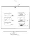
図3は、物理サーバ200上で稼働する第一のストレージコントローラLPAR113および第二のストレージコントローラLPAR123の構成の一例を示す図である。仮想化機構300、LPAR310、ストレージコントローラLPAR320はプログラム207であり、これらは予め記録媒体に記録され、この記録媒体から読み出されてメモリ202に格納される。 FIG. 3 is a diagram illustrating an example of the configuration of the first
仮想化機構300はLPAR制御プログラム301と、リソース割当プログラム302を備えたプログラムである。LPAR制御プログラム301は、LPAR310やストレージコントローラLPAR320の作成、削除などの機能を持つ。リソース割当プログラム302は、物理サーバ200の持つリソースを論理分割し、LPAR310やストレージコントローラLPAR320に論理分割したリソースを割り当てる機能を持つ。この機能により、LPAR310やストレージコントローラLPAR320を同一の物理サーバ200上で複数稼働することができる。 The
LPAR310は、仮想化機構300から割り当てられたリソースを利用してプログラム311を実行する。ここで、LPAR310が実行するプログラム311とは、例えばOSやアプリケーション、仮想化機構などである。 The LPAR 310 executes the
ストレージコントローラLPAR320は、LPAR310の一種であり、OS321に加え、ストレージコントローラ管理プログラム322、外部ストレージ接続プログラム323、物理ディスク制御プログラム324、仮想ディスク制御プログラム325、管理情報更新プログラム326を備えたLPARである。これらのプログラムもストレージコントローラLPAR320と合わせて、メモリ202に格納される。ストレージコントローラLPAR320は、OS321上に前記プログラム322〜326をインストールし、仮想化機構300のLPAR310上で動作するように設定された仮想アプライアンスである。システム管理者は、ストレージコントローラLPARの仮想アプライアンスをあらかじめ仮想化機構300に導入しておく。 The storage controller LPAR 320 is a kind of LPAR 310 and is an LPAR including an OS 321, a storage controller management program 322, an external
以降、各プログラムを主語として実行される処理を説明するが、実際にはプロセッサ201がメモリ202から各プログラムを読み出し、各プログラムの処理を実行することを意味する。 Hereinafter, processing executed with each program as a subject will be described. In practice, this means that the
OS321は、例えばLinuxやWindows(登録商標)などの一般的なOperating Systemであり、ストレージコントローラLPAR320が備える各種のプログラムを実行する。 The OS 321 is a general operating system such as Linux or Windows (registered trademark), and executes various programs provided in the storage controller LPAR320.
ストレージコントローラ管理プログラム322は、ネットワーク130を介して管理サーバ100と接続し、物理サーバ200上で稼働するLPAR310や物理サーバ200が備える内蔵ディスク117、仮想ディスク125の設定を管理するほか、管理サーバ100が発行する要求を受信し、外部ストレージ接続プログラム323、物理ディスク制御プログラム324、仮想ディスク制御プログラム325に要求を送信する。また、仮想化機構300のLPAR制御プログラム301やリソース割当プログラム302に対しても要求を送信する。 The storage controller management program 322 is connected to the
外部ストレージ接続プログラム323は、ネットワーク130を介して異なる物理サーバ200上のストレージコントローラLPAR320の外部ストレージ接続プログラム323同士が接続することにより、LPAR310がおよび仮想ディスク125に対して発行するディスク入出力命令を送受信する。また、外部ストレージ接続プログラム323は、同じサーバ上のストレージコントローラLPAR320の物理ディスク制御プログラム324や仮想ディスク制御プログラム325と接続し、前記ディスク入出力命令を送信し、前記ディスク入出力命令の結果を受信する。 The external
物理ディスク制御プログラム324は、外部ストレージ接続プログラム323からディスク入出力命令を受信し、同じサーバに搭載された内蔵ディスク117に対して、前記ディスク入出力命令を実行する。 The physical
仮想ディスク制御プログラム325は、ストレージコントローラ管理プログラム322の要求に応じて、内蔵ディスク117に対応した仮想ディスク125を作成する。また、仮想化機構300のリソース割当プログラム302に対して仮想ディスクアダプタ124作成要求を送信し、仮想ディスクアダプタ124を介して第二のLPAR122と仮想ディスク125を接続する。外部ストレージ接続プログラム323からディスク入出力命令を受信し、同じサーバ上の仮想ディスク125に対して、前記ディスク入出力命令を実行する。また、仮想化機構300のLPAR制御プログラム301に対し、仮想ディスク125の作成要求を送信する。 The virtual
なお、サーバ200が内蔵ディスク117を備えていない場合、物理ディスク制御プログラム324は実行されない。同様に、サーバ200が仮想ディスク125を備えていない場合、仮想ディスク制御プログラム325は実行されない。いずれの場合も、ストレージコントローラLPAR320は全てのプログラムを備えているが、サーバ200の構成に応じて実際に実行するプログラムが異なる。 If the
管理情報更新プログラム326は、ネットワーク130を介して管理サーバ100のディスク共有管理プログラム403と接続し、管理サーバ100が保持する各種の情報を更新する。 The management information update program 326 is connected to the disk sharing management program 403 of the
図4は、管理サーバ100の詳細構成の一例を示す図である。管理サーバ100は、OS401と、ストレージコントローラ制御プログラム402と、ディスク共有管理プログラム403と、ディスク割当管理情報411と、ストレージコントローラ管理情報412と、ディスク共有管理情報413と、をメモリ202に格納する。これらのプログラムおよび情報は、あらかじめ記録媒体に記録され、この記録媒体から読み出されてメモリ202に格納される。以降、各プログラムを主語として実行される処理を説明するが、実際にはプロセッサ201がメモリ202から各プログラムを読み出し、各プログラムの処理を実行することを意味する。 FIG. 4 is a diagram illustrating an example of a detailed configuration of the
ストレージコントローラ制御プログラム402は、ネットワーク130を介してストレージコントローラLPAR320のストレージコントローラ管理プログラム322と接続し、第一のLPAR112と第二のLPAR122との間で内蔵ディスク117を共有する処理の開始や終了を指示する。 The storage
ディスク共有管理プログラム403は、管理サーバ100が保持するディスク割当管理情報411や、ストレージコントローラ管理情報412や、ディスク共有管理情報413の情報を更新し、ディスク共有処理の全体を管理する。 The disk sharing management program 403 updates the disk allocation management information 411, the storage
なお、管理サーバ100の構成は図4に示した構成に限らず、図3で示したような、仮想化機構300によって仮想化された構成でも良い。この場合、管理サーバ100の各プログラムと各情報は、LPAR310のプログラム311に相当する。 The configuration of the
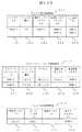
図5は、ディスク割当管理情報411の一例を示す図である。なお、図5に記載のディスク割当管理情報411のフォーマットは一例であって、図5に示したフォーマットに限定されるものではない。 FIG. 5 is a diagram illustrating an example of the disk allocation management information 411. The format of the disk allocation management information 411 described in FIG. 5 is an example, and is not limited to the format shown in FIG.
ディスク割当管理情報411は、システム内に存在する内蔵ディスク117や仮想ディスク125などのディスク全般の割り当て状態を管理するテーブルである。ディスク割当管理情報411は、前記ディスクを一意に識別する識別子(以下、ID)のディスクID501と、前記ディスクの種類を判別するディスク種別502と、前記ディスクに接続する物理ディスクアダプタを一意に識別する物理ディスクアダプタID503と、前記ディスクに接続する仮想ディスクアダプタを一意に識別する仮想ディスクアダプタID504と、前記ディスクが割り当てられているLPARを一意に識別するLPAR ID505と、を格納する。 The disk allocation management information 411 is a table for managing the allocation status of all disks such as the
ディスク種別欄502には、物理ディスクと仮想ディスクなどのディスク種類を判別する情報を格納する。ディスクの種別が物理ディスクである場合、ハードディスクドライブ(HDD)やソリッドステートドライブ(SSD)などの物理ディスクの実装方式を格納してもよい。また、ディスクの種別が仮想ディスクである場合、仮想ディスクを作成したプログラムの種類やバージョンなどを格納もよい。システム管理者はこれらの情報を参照することで、ディスクの性能や特性を考慮して共有するディスクを選定することができる。 The
なお、前記ディスクの種別が仮想ディスクであり、接続する物理ディスクアダプタが存在しない場合、物理ディスクアダプタID欄503は空欄としてもよい。 When the disk type is a virtual disk and there is no physical disk adapter to be connected, the physical disk
図6は、ストレージコントローラ管理情報412の一例を示す図である。なお、図6に記載のストレージコントローラ管理情報412のフォーマットは一例であって、図6に示したフォーマットに限定されるものではない。 FIG. 6 is a diagram illustrating an example of the storage
ストレージコントローラ管理情報412は、システム内に存在するストレージコントローラLPAR320などのストレージコントローラ全般を管理するテーブルである。ストレージコントローラ管理情報412には、前記ストレージコントローラを一意に識別するストレージコントローラID601と、前記ストレージコントローラの種類を判別するストレージコントローラ種別602と、前記ストレージコントローラと接続するためのストレージコントローラアドレス603と、前記ストレージコントローラが管理しているディスクの一覧を表す管理対象ディスクID604と、前記ストレージコントローラが管理しているLPARの一覧を表す管理対象LPAR605と、を格納する。 The storage
ストレージコントローラ種別欄602には、前記ストレージコントローラの種別を判別する情報を格納する。例えば共有ストレージのストレージコントローラなど、ストレージコントローラLPAR320とは実装の異なるストレージコントローラがシステム内に存在する場合、その実装を表す情報をストレージコントローラ種別欄602に格納して良い。 The storage
アドレス欄603には、管理サーバ100や仮想化機構300やLPAR310やストレージコントローラLPAR320などが、前記ストレージコントローラに接続するために指定する、例えばIPアドレスなどの宛先アドレスを格納する。 The
管理対象ディスクID欄604には、前記ストレージコントローラが管理する内蔵ディスク117や仮想ディスク125のIDを格納する。前記ストレージコントローラは、前記ストレージコントローラが稼働する装置と同一の装置に搭載された内蔵ディスク117や、前記装置の上に作成された仮想ディスク125を管理する。例えば、図1における第一のストレージコントローラLPAR113は、第一のサーバ110に搭載された内蔵ディスク117を管理し、図1における第二のストレージコントローラLPAR125は、第二のサーバ120に作成された仮想ディスク125を管理する。 The managed
図7は、ディスク共有管理情報413の一例を示す図である。なお、図7に記載のディスク共有管理情報413のフォーマットは一例であって、図7に示したフォーマットに限定されるものではない。 FIG. 7 is a diagram illustrating an example of the disk sharing management information 413. The format of the disk sharing management information 413 shown in FIG. 7 is an example, and is not limited to the format shown in FIG.
ディスク共有管理情報413は、第一のLPAR112と第二のLPAR122との間で内蔵ディスク117を共有する場合に、内蔵ディスク117とそれに対応する仮想ディスク125との対応関係を管理するテーブルである。 The disk sharing management information 413 is a table for managing the correspondence between the
ディスク共有管理情報413には、第一のサーバ110が備える共有対象の内蔵ディスク117を一意に識別する内蔵ディスクID701と、第一のサーバ110上で稼働し内蔵ディスク117が割り当てられた第一のLPAR112を一意に識別する第一のLPAR ID702と、第二のサーバ120上に新たに作成され内蔵ディスク117に対応する仮想ディスク125を一意に識別する仮想ディスクID703と、第二のサーバ120上で稼働し仮想ディスク125を新たに割り当てる第二のLPAR122を一意に識別する第二のLPAR ID704とを格納する。 The disk sharing management information 413 includes an
ディスク共有管理情報413に新たな行が挿入されることで、新たにディスク共有が開始されたことを表す。同様に、ディスク共有管理情報413から行が削除されることで、ディスク共有が終了したことを表す。ディスク共有管理情報413は、内蔵ディスク117と仮想ディスク125との対応関係を示している。したがって、第一のストレージコントローラLPARや第二のストレージコントローラLPARが、ディスク共有管理情報413を参照することによって、内蔵ディスク117と共有関係にある仮想ディスク125を特定できる。 Inserting a new line into the disk sharing management information 413 indicates that a new disk sharing has started. Similarly, deletion of a row from the disk sharing management information 413 indicates that disk sharing has ended. The disk sharing management information 413 indicates a correspondence relationship between the
次に、実施例において、第一のサーバ110で稼働する第一のLPAR112と、第二のサーバ120で稼働する第二のLPAR122との間で、第一のサーバ110に搭載された内蔵ディスク117の共有を開始する処理の手順を、図8のフローチャートに基づいて説明する。 Next, in the embodiment, the
本処理を開始する前のシステムの状態の一例を図9Aと図9Bに示す。図9Aがシステム構成、図9Bが図5のディスク割当管理情報411と、図6のストレージコントローラ管理情報412と、図7のディスク共有管理情報413と、の各情報の状態である。以下では、図1と図5、図6、図7の差異のみ説明する。第一のストレージコントローラLPAR113と、第二のLPAR122と、第二のストレージコントローラLPAR123は、仮想ディスクアダプタを割り当てられておらず、図内のいずれのディスクとも接続されていない。このときに、第一のLPAR112と第二のLPAR122が内蔵ディスク117を共有する要求があるとする。 An example of the state of the system before starting this processing is shown in FIGS. 9A and 9B. 9A shows the system configuration, and FIG. 9B shows the status of each of the disk allocation management information 411 in FIG. 5, the storage
図8は、LPAR間で内蔵ディスクの共有を開始する処理の手順の一例を示すフローチャートである。本処理は例えば、システムの管理者が管理サーバ100に対し、第一のLPAR112と第二のLPAR122とによる内蔵ディスク117のディスク共有開始要求を送信することを契機に実行される。このとき、前記要求の送信者は、第一のLPAR112のIDと、第二のLPAR122のIDと、共有対象の内蔵ディスク117のIDを、管理サーバ100のディスク共有管理プログラム403に対し送信する。なお、本処理を実行する契機は、システム管理者からの要求に限らず、任意のプログラムからの前記要求の送信であってもよい。 FIG. 8 is a flowchart illustrating an example of a processing procedure for starting sharing of the internal disk between LPARs. This process is executed, for example, when the system administrator transmits a disk sharing start request for the
ステップ801において、管理サーバ100のディスク共有管理プログラム403は、ディスク共有開始要求と、第一のLPAR112のIDと、第二のLPAR122のIDと、共有対象の内蔵ディスク117のIDを受信する。続いて、ディスク共有管理プログラム403は、ディスク共有管理情報413に新たな行を挿入し、受信した内蔵ディスク117のIDと、第一のLPAR112のIDと、第二のLPAR122のIDとを、それぞれディスク共有管理情報413の内蔵ディスクID欄701と、第一のLPAR ID欄702と、第二のLPAR ID欄704に記録する。このとき、仮想ディスクは作成されていないため、仮想ディスクID欄703は空欄である。 In
ステップ802において、管理サーバ100のディスク共有管理プログラム403は、ステップ801で取得した内蔵ディスクIDを元に、ストレージコントローラ管理情報412の管理対象ディスクID欄604を検索し、内蔵ディスク117を管理する第一のストレージコントローラLPAR113のアドレスを、アドレス欄603から取得する。続いて、ステップ801で取得した第一のLPAR IDを元に、ストレージコントローラ管理情報412の管理対象LPAR欄605を検索し、第一のLPAR112を管理する第一のストレージコントローラLPAR113のアドレスを、アドレス欄603から取得する。同様に、第二のLPAR122を管理する第二のストレージコントローラLPAR123のアドレスも取得する。 In
図6を例に説明すると、内蔵ディスク117のIDであるDisk1−1をキーとしてストレージコントローラ管理情報412を検索すると、第一のストレージコントローラLPARのIDであるLPAR1−2の行が得られる。ここで、得られた行のアドレス欄603を参照することで、内蔵ディスク117を管理する第一のストレージコントローラLPARのアドレスは192.0.2.10であると判明する。 Referring to FIG. 6 as an example, when the storage
ここで、ストレージコントローラ管理情報412の検索において、ストレージコントローラの行を複数発見することがある。複数のストレージコントローラで一つの内蔵ディスクやLPARを管理する目的は、多くの場合ストレージコントローラ管理情報の冗長化である。このときは、システム管理者が予めストレージコントローラ種別欄602に冗長構成の主系と従系などの情報を記録しておく。これにより、ストレージコントローラを複数発見したときに、いずれのストレージコントローラを選択すればよいか判断できる。 Here, in the search of the storage
ステップ803において、管理サーバ100のストレージコントローラ制御プログラム402は、ステップ802で取得した第一のストレージコントローラLPAR113のアドレスを使い、第一のストレージコントローラLPAR113に対し、ディスク共有開始命令と、ステップ801で取得した共有対象の内蔵ディスク117のID、第一のLPAR112のID、第二のLPAR122のIDに加え、ステップ802で取得した第二のストレージコントローラLPAR123のアドレスを送信する。 In
ステップ804において、第一のストレージコントローラLPAR113のストレージコントローラ管理プログラム322は、ステップ803で管理サーバ100が送信した要求やIDなどの情報を受信する。続いて、ストレージコントローラ管理プログラム322は、第一の仮想化機構111のリソース割当プログラム302に対し、仮想ディスクアダプタ作成要求と、内蔵ディスク117のIDと、第一のストレージコントローラLPAR113のIDと、を送信する。このとき、ストレージコントローラ管理プログラム322が第一の仮想化機構111に対して前記要求や前記IDを送信するには、例えばハイパーコールなどの、LPARが仮想化機構に対して情報を伝達できる特殊な命令を利用する。あるいは、ネットワークを介して仮想化機構に接続し、仮想化機構が提供するAPI(Application Program Interface)命令を発行してもよい。 In
リソース割当プログラム302はストレージコントローラ管理プログラム322からの情報を受信し、仮想ディスクアダプタ115を作成する。このとき、リソース割当プログラム302は、仮想ディスクアダプタ115を一意に識別するためのIDも生成する。また、リソース割当プログラム302は、第一のストレージコントローラLPAR113のIDを元に仮想ディスクアダプタ115を第一のストレージコントローラLPAR113に割り当て、内蔵ディスク117のIDを元に仮想ディスクアダプタ115を内蔵ディスク117に接続する。この後、リソース割当プログラム302は、生成した前記IDをストレージコントローラ管理プログラム322に送信する。この処理により、第一のストレージコントローラLPAR113は、内蔵ディスク117にディスク入出力命令を発行し、データの読み書きを行えるようになる。このときのリソース割当プログラム302の処理は、仮想化機構111が一般的に持つ仮想ディスクアダプタの作成処理と物理ディスクの割り当て処理である。また、仮想ディスクアダプタのIDは、例えばWWN(World Wide Name)などである。 The resource allocation program 302 receives information from the storage controller management program 322 and creates a
続いて、ストレージコントローラ管理プログラム322は、管理情報更新プログラム326を介して管理サーバ100に接続し、ディスク割当管理情報411を更新する。具体的には、管理情報更新プログラム326は、内蔵ディスク117のIDを元にディスク割当管理情報411のディスクID欄501を検索し、得られた行の仮想ディスクアダプタID欄504に、リソース割当プログラム302から受け取った仮想ディスクアダプタ115のIDを登録する。合わせて、LPAR ID欄505に、仮想ディスクアダプタ115を割り当てた第一のストレージコントローラLPAR113のIDを登録する。 Subsequently, the storage controller management program 322 connects to the
仮想ディスクアダプタ115の作成後、第一のストレージコントローラLPAR113は、第二のストレージコントローラLPAR123からの通信を待つ。 After creating the
このときのシステムの状態の一例を図10Aと図10Bに示す。図9と比較して、新たに仮想ディスクアダプタ115が作成され、ストレージコントローラLPAR113が仮想ディスクアダプタ115を介して内蔵ディスク117に接続している。 An example of the state of the system at this time is shown in FIGS. 10A and 10B. Compared to FIG. 9, a new
ステップ805において、管理サーバ100のストレージコントローラ制御プログラム402は、ステップ802で取得した第二のストレージコントローラLPAR123のアドレスを使い、第二のストレージコントローラLPAR123に対し、ディスク共有開始命令と、ステップ801で取得した共有対象の内蔵ディスク117のID、第一のLPARのID、第二のLPARのIDに加え、ステップ802で取得した第一のストレージコントローラLPAR113のアドレスを送信する。 In
ステップ806において、第二のストレージコントローラLPAR123のストレージコントローラ管理プログラム322は、ステップ805で管理サーバ100が送信した要求やIDなどの情報を受信する。続いて、ストレージコントローラ管理プログラム322は、外部ストレージ接続プログラム323に対して第一のストレージコントローラLPAR113との接続要求を送信する。 In
外部ストレージ接続プログラム323は、ステップ805で受け取った第一のストレージコントローラLPAR113のアドレスを使い、ネットワーク130を介して第一のストレージコントローラLPAR113に接続要求を送信する。第一のストレージコントローラLPAR113の外部ストレージ接続プログラム323は、第二のストレージコントローラLPAR123の接続要求を受信すると、第一のストレージコントローラLPAR113と第二のストレージコントローラLPAR123との間で通信を確立する。ここで、通信の確立とは、両者が互いに情報を送受信できるように準備することであり、例えばIP(Internet Protocol)のセッションを張ることである。 The external
ステップ807において、ストレージコントローラ管理プログラム322は、仮想ディスク制御プログラム325に対し、仮想ディスク作成要求と、第二のLPAR122のIDと、第二のストレージコントローラLPAR123のIDと、を送信する。 In
仮想ディスク制御プログラム325は、ストレージコントローラ管理プログラム322からの情報を受信し、仮想ディスク125を作成する。また、仮想ディスク制御プログラム325は、作成した仮想ディスク125を一意に識別するためのIDを生成する。 The virtual
ここで、仮想ディスク125は、仮想ディスク制御プログラム325が内蔵ディスク117を模擬して作成されたものである。仮想ディスク125は、例えばSCSIコマンドなどのディスク入出力命令を受け付けることができる。従って、仮想ディスク125は、ディスク入出力命令の宛先として指定できるIDを持ち、例えばLUN(Logical Unit Number)を持つ。 Here, the
仮想ディスク125の作成後、仮想ディスク制御プログラム325は、生成した仮想ディスク125のIDをストレージコントローラ管理プログラム322に送信する。 After creating the
続いて、ストレージコントローラ管理プログラム322は、管理情報更新プログラム326を介して管理サーバ100に接続し、ディスク割当管理情報411を更新する。具体的には、管理情報更新プログラム326は、ディスク割当管理情報411に新しい行を挿入し、ディスクID欄501に仮想ディスク制御プログラム325から受け取った仮想ディスク125のIDを、ディスク種別欄502に仮想ディスクを表す情報を、LPAR ID欄505に第二のストレージコントローラLPAR123のIDを、登録する。仮想ディスク125の場合、物理ディスクアダプタには接続しないため、物理ディスクアダプタID欄503は空欄のままである。また、仮想ディスク125に接続する仮想ディスクアダプタを作成していないため、仮想ディスクアダプタID欄504も空欄のままである。 Subsequently, the storage controller management program 322 connects to the
また、ストレージコントローラ管理プログラム322は、管理情報更新プログラム326を介して管理サーバ100に接続し、ストレージコントローラ管理情報412を更新する。具体的には、ストレージコントローラ管理プログラム322は、第二のストレージコントローラLPAR123のIDを元にストレージコントローラ管理情報412のストレージコントローラID欄601を検索し、取得した行の管理対象ディスク欄604に仮想ディスク125のIDを登録する。以上の処理により、仮想ディスク125が第二のストレージコントローラLPAR123の管理下に入ったことを表す。 The storage controller management program 322 connects to the
このときのシステムの状態の一例を図11Aと図11Bに示す。図10と比較して、新たに第二のストレージコントローラLPAR123上に仮想ディスク125が作成されている。 An example of the state of the system at this time is shown in FIGS. 11A and 11B. Compared to FIG. 10, a
ステップ808において、ストレージコントローラ管理プログラム322は、第二の仮想化機構121のリソース割当プログラム302に対し、仮想ディスクアダプタ作成要求と、第二のLPAR122のIDと、第二のストレージコントローラLPAR123のIDと、仮想ディスク125のIDとを、ハイパーコールやAPIなどを利用して送信する。 In
リソース割当プログラム302は、ストレージコントローラ管理プログラム322からの情報を受信し、仮想ディスクアダプタ124を作成し、仮想ディスクアダプタ124を第二のLPAR122のIDを元に第二のLPAR122に割り当て、仮想ディスク125のIDを元に仮想ディスクアダプタ124を仮想ディスク125に接続する。また、仮想ディスクアダプタ124は、ストレージコントローラ管理プログラム322が送信した第二のストレージコントローラLPAR123のIDを保持しておく。このとき、仮想ディスクアダプタ124のIDを合わせて生成し、ストレージコントローラ管理プログラム322に返す処理はステップ804やステップ807と同様である。 The resource allocation program 302 receives the information from the storage controller management program 322, creates the
続いて、ストレージコントローラ管理プログラム322は、管理情報更新プログラム326を介して管理サーバ100に接続し、ディスク割当管理情報411を更新する。具体的には、管理情報更新プログラム326は、仮想ディスク125のIDを元にディスク割当管理情報411のディスクID欄501を検索し、取得した行の仮想ディスクアダプタID欄504にリソース割当プログラム302から受け取った仮想ディスクアダプタ124のIDを、LPAR ID欄505に第二のLPAR122のIDを、登録する。 Subsequently, the storage controller management program 322 connects to the
また、ストレージコントローラ管理プログラム322は、管理情報更新プログラム326を介して管理サーバ100に接続し、ディスク共有管理情報413を更新する。具体的には、まず、内蔵ディスク117のIDを元に、ディスク共有管理情報413の内蔵ディスクID欄701を検索する。次に、検索により取得した内蔵ディスク117のIDが一致する行において、空欄の仮想ディスクID欄703に、ステップ807にて生成された仮想ディスク125のIDを、登録する。 The storage controller management program 322 connects to the
以上の手順により、第一のサーバ110におけるストレージコントローラLPAR113と第二のサーバ120におけるストレージコントローラLPAR123とが、ディスク共有管理情報413を管理サーバ100を介して共有しているので、内蔵ディスク117を模擬した仮想ディスク125を特定でき、第一のLPAR112と第二のLPAR122とが内蔵ディスク117の共有を開始可能となる。これにより、第二のLPAR122は、仮想ディスクアダプタ124に対してディスク入出力命令を発行することで、内蔵ディスク117に保存されたデータを読み書きできるようになる。 By the above procedure, the
このときのシステム構成の一例が図1であり、ディスク割当管理情報411やストレージコントローラ管理情報412やディスク共有管理情報413の状態が、それぞれ図5、図6、図7である。 An example of the system configuration at this time is shown in FIG. 1, and the states of the disk allocation management information 411, the storage
次に、第二のLPAR122が仮想ディスクアダプタ124に対してディスク入出力命令を発行し、内蔵ディスク117に保存されたデータを読み書きする際の処理の手順を、図12を使いフローチャートにより説明する。 Next, the processing procedure when the
ステップ1201において、第二のLPAR122上で稼働するプログラム311は、第二の仮想化機構121により第二のLPAR122に割り当てられた仮想ディスクアダプタ124に対し、仮想ディスク125のディスク入出力命令を発行する。 In step 1201, the
ここで、前記ディスク入出力命令は、第二のLPAR122上で稼働するプログラム311が仮想ディスクアダプタ124を介して仮想ディスク125に保存されたデータを読み書きする一般的な命令であり、例えばSCSIコマンドである。従って、前記ディスク入出力命令には、命令を発行する対象のディスクである内蔵ディスク117のIDと、入出力処理の内容が含まれている。 Here, the disk input / output command is a general command in which the
ステップ1202において、仮想ディスクアダプタ124は、第二のLPAR122が発行した前記ディスク入出力命令を受信する。ここで、一般的な仮想化機構において、第二のLPAR122が発行するディスク入出力命令は仮想化機構121が処理すべき特殊な命令であるため、前記ディスク入出力命令は仮想化機構121のLPAR制御プログラム301によりトラップされ、プロセッサ201により処理されるプログラム207が、第二のLPAR122から仮想ディスクアダプタ124に移る。従って、前記ディスク入出力命令の受信とは、例えばLPAR制御プログラム301がトラップ処理により受信した前記ディスク入出力命令を、仮想ディスクアダプタ124に受け渡す処理である。 In step 1202, the
続けて、仮想ディスクアダプタ124は、ステップ808において仮想ディスクアダプタ124が受信した第二のストレージコントローラLPAR123のIDを使い、前記ディスク入出力命令を、第二のストレージコントローラLPAR123に対して送信する。ここで、前記ディスク入出力命令の送信方法は、例えば仮想ディスクアダプタ124から第二のストレージコントローラLPAR123へのLPAR制御プログラム301を介した割り込みの発行である。 Subsequently, the
ステップ1203において、第二のストレージコントローラLPAR122の仮想ディスク制御プログラム325は、仮想ディスクアダプタ124が送信した前記ディスク入出力命令を受信し、第二のストレージコントローラLPAR123の外部ストレージ接続プログラム323に対し、前記ディスク入出力命令を転送する。 In step 1203, the virtual
続けて、外部ストレージ接続プログラム323は、ストレージコントローラ管理プログラム322を介して管理サーバ100のストレージコントローラ管理情報412を参照し、前記ディスク入出力命令に含まれる内蔵ディスク117のIDを元に、ストレージコントローラ管理情報412の管理対象ディスク欄604を検索する。その後、外部ストレージ接続プログラム323は、検索により得られた行のアドレス欄603から第一のストレージコントローラLPAR113のアドレスを取得する。ここで、外部ストレージ接続プログラム323は、管理サーバ100へ接続するのではなく、外部ストレージ接続プログラム323内に内蔵ディスク117のIDと第一のストレージコントローラLPAR113のアドレスとの組み合わせをキャッシュしておき、それを参照してもよい。 Subsequently, the external
続けて、外部ストレージ管理プログラム323は、取得した前記アドレスを使い、ステップ806で確立した通信を通して、第一のストレージコントローラLPAR113に対し、ネットワーク130を介して前記ディスク入出力命令を送信する。ここで、前記ディスク入出力命令の送信方法は、外部ストレージ接続プログラム323が前記ディスク入出力命令に対し、ネットワーク130が採用するIPなどの通信プロトコルに合わせてヘッダを付加することで前記ディスク入出力命令をカプセル化し、ネットワーク130を介して送信する送信方法であり、例えばiSCSIである。 Subsequently, the external
ステップ1204において、第一のストレージコントローラLPAR113の外部ストレージ接続プログラム323は、第二のストレージコントローラLPAR123から転送された前記カプセル化したディスク入出力命令を受信し、前記カプセル化したディスク入出力命令から第二のストレージコントローラLPARの外部ストレージ接続プログラム323が付加したヘッダを除去することで、前記ディスク入出力命令を取り出す。続けて、第一のストレージコントローラLPAR113の外部ストレージ接続プログラム323は、前記ディスク入出力命令に含まれる内蔵ディスク117のIDを元に、第一のストレージコントローラLPAR113の物理ディスク制御プログラム324に対し前記ディスク入出力命令を発行する。 In step 1204, the external
物理ディスク制御プログラム324は、仮想ディスクアダプタ115を介し、内蔵ディスク117に対し前記ディスク入出力命令を発行する。また、物理ディスク制御プログラム324は、内蔵ディスク117に対して発行された前記ディスク入出力命令の結果を、仮想ディスクアダプタ115を介して受け取る。ここで、物理ディスク制御プログラム324が前記ディスク入出力命令を発行し、その結果を受け取る処理は、一般的な仮想化機構が備えるディスク入出力処理である。 The physical
ステップ1205において、第一のストレージコントローラLPAR113の物理ディスク制御プログラム324は、前記ディスク入出力命令の結果を第一のストレージコントローラLPAR113の外部ストレージ接続プログラム323に転送する。 In step 1205, the physical
続けて、外部ストレージ接続プログラム323は、ストレージコントローラ管理プログラム322を介して管理サーバ100のディスク共有管理情報413を参照し、前記ディスク入出力命令に含まれる内蔵ディスク117のIDを元に、ディスク共有管理情報413の内蔵ディスクID欄701を検索する。その後、外部ストレージ接続プログラム323は、検索により得られた行の仮想ディスクID欄703から、内蔵ディスク117に対応する仮想ディスク125のIDを取得する。次に、外部ストレージ接続プログラム323は、管理サーバ100のストレージコントローラ管理情報412の管理対象ディスク欄604を、前記仮想ディスクIDを元に検索し、得られた行のアドレス欄603から、仮想ディスク125を管理する第二のストレージコントローラLPARのアドレスを取得する。ここで、外部ストレージ接続プログラム323は、管理サーバ100へ接続するのではなく、外部ストレージ接続プログラム323内に内蔵ディスク117のIDと、仮想ディスク125のIDと、第二のストレージコントローラLPAR123のアドレスの組み合わせをキャッシュしておき、それを参照してもよい。 Subsequently, the external
続けて、外部ストレージ接続プログラム323は、取得したアドレスを使い、第二のストレージコントローラLPAR123に対し、前記ディスク入出力命令の結果を送信する。ここで、前記ディスク入出力命令の結果の送信方法は、ステップ1203で記述した送信方法と同様であり、前記ディスク入出力命令の結果に対し、ネットワーク130が採用する通信プロトコルに合わせたヘッダを付加することで、前記ディスク入出力命令の結果をカプセル化し、ネットワーク130を介して送信する送信方法である。 Subsequently, the external
ステップ1206において、第二のストレージコントローラLPAR123の外部ストレージ接続プログラム323は、第一のストレージコントローラLPAR113が送信した前記カプセル化したディスク入出力命令の結果を受信し、前記カプセル化したディスク入出力命令の結果から、第一のストレージコントローラLPARの外部ストレージ接続プログラム323が付加したヘッダを除去することで、前記ディスク入出力命令の結果を取り出す。続けて、第二のストレージコントローラLPAR123の外部ストレージ接続プログラム323は、仮想ディスク制御プログラム325に対し、前記ディスク入出力命令の結果を送信する。 In step 1206, the external
続けて、仮想ディスク制御プログラム325は、第二のLPAR122に対して前記ディスク入出力命令の結果を送信する。具体的には、仮想ディスク制御プログラム325は、第二の仮想化機構121の仮想ディスクアダプタ124に対し、例えばハイパーコールやAPIなどを利用して前記ディスク入出力命令の結果を送信する。仮想ディスクアダプタ124は、例えば割り込み命令などの、仮想化機構がLPARに対して情報を伝達できる命令を利用して、前記ディスク入出力命令の結果を第二のLPAR122に対し送信する。 Subsequently, the virtual
以上の手順により、第二のLPAR122が仮想ディスクアダプタ124に対して入出力命令を発行し、内蔵ディスク117に保存されたデータを読み書きする際の処理を実現できる。これにより、高価な共有ストレージを不要とし、安価な内蔵ディスクを採用することによるコスト削減と、ディスク共有による利便性を両立できるという効果を有する。 Through the above procedure, the
100 管理サーバ、110 第一のサーバ、120 第二のサーバ、111および121 仮想化機構、112および122 LPAR、113および123 ストレージコントローラLPAR、114および115および124 仮想ディスクアダプタ、116 物理ディスクアダプタ、117 内蔵ディスク、125 仮想ディスク、200 物理サーバ、201 プロセッサ、202 メモリ、203 ネットワークアダプタ、204 ディスクアダプタ、205 入出力装置、206 システムバス、207 プログラム、300 仮想化機構、301 LPAR制御プログラム、302 リソース割当プログラム、310 LPAR、311 プログラム、320 ストレージコントローラLPAR、321 OS、322 ストレージコントローラ管理プログラム、323 外部ストレージ接続プログラム、324 物理ディスク制御プログラム、325 仮想ディスク制御プログラム、326 管理情報更新プログラム、401 OS、402 ストレージコントローラ制御プログラム、403 ディスク共有管理プログラム、411 ディスク割当管理情報、412 ストレージコントローラ管理情報、413 ディスク共有管理情報、501ないし505 テーブル内データ、601ないし605 テーブル内データ、701ないし704 テーブル内データ、801ないし808 処理ステップ、1201ないし1206 処理ステップ100 Management Server, 110 First Server, 120 Second Server, 111 and 121 Virtualization Mechanism, 112 and 122 LPAR, 113 and 123 Storage Controller LPAR, 114 and 115 and 124 Virtual Disk Adapter, 116 Physical Disk Adapter, 117 Internal disk, 125 virtual disk, 200 physical server, 201 processor, 202 memory, 203 network adapter, 204 disk adapter, 205 input / output device, 206 system bus, 207 program, 300 virtualization mechanism, 301 LPAR control program, 302 resource allocation Program, 310 LPAR, 311 program, 320 storage controller LPAR, 321 OS, 322 storage controller Management program, 323 external storage connection program, 324 physical disk control program, 325 virtual disk control program, 326 management information update program, 401 OS, 402 storage controller control program, 403 disk sharing management program, 411 disk allocation management information, 412 Storage controller management information, 413 Disk sharing management information, 501 to 505 table data, 601 to 605 table data, 701 to 704 table data, 801 to 808 processing steps, 1201 to 1206 processing steps
Claims (12)
Translated fromJapanese第一の物理サーバは、内蔵ディスクと、第一の仮想化機構と、前記第一の仮想化機構により論理分割された第一のLPAR及び第一のストレージコントローラLPARと、を備え、
第二の物理サーバは、第二の仮想化機構と、前記第二の仮想化機構により論理分割された第二のLPAR及び第二のストレージコントローラLPARと、前記第二のストレージコントローラLPARにより前記第一の物理サーバの前記内蔵ディスクを模擬して生成された仮想ディスクと、を備え、
前記第一のストレージコントローラLPARと、前記第二のストレージコントローラLPARとは相互に通信し、
前記第二のストレージコントローラLPARは、前記第二のLPARが発行した前記仮想ディスクのディスク入出力命令を、前記第一のストレージコントローラLPARに転送し、
前記第一のストレージコントローラLPARは、前記ディスク入出力命令を参照して、前記ディスク入出力命令に含まれる内蔵ディスクの識別子を取得し、前記取得した識別子に対応する前記内蔵ディスクに対して、前記ディスク入出力命令を実行することを特徴とするディスク共有方法。In a disk sharing method in a system including a plurality of physical servers and a management server connected to the plurality of physical servers,
The first physical server includes an internal disk, a first virtualization mechanism, and a first LPAR and a first storage controller LPAR that are logically partitioned by the first virtualization mechanism,
The second physical server includes a second virtualization mechanism, a second LPAR and a second storage controller LPAR logically partitioned by the second virtualization mechanism, and the second storage controller LPAR. A virtual disk generated by simulating the internal disk of one physical server,
The first storage controller LPAR and the second storage controller LPAR communicate with each other;
The second storage controller LPAR transfers a disk input / output command of the virtual disk issued by the second LPAR to the first storage controller LPAR,
The first storage controller LPAR refers to the disk input / output command to acquire an identifier of the internal disk included in the disk input / output command, and for the internal disk corresponding to the acquired identifier, A disk sharing method characterized by executing a disk input / output instruction.
前記第二のストレージコントローラLPARは、前記転送されたディスク入出力命令の結果を、前記第二のLPARに転送することを特徴とする請求項1記載のディスク共有方法。The first storage controller LPAR transfers the result of the executed disk input / output command to the second storage controller LPAR,
2. The disk sharing method according to claim 1, wherein the second storage controller LPAR transfers a result of the transferred disk input / output command to the second LPAR.
前記第二のLPARは、第二の仮想ディスクアダプタを介して前記第二のストレージコントローラLPARに接続することを特徴とする請求項1記載のディスク共有方法。The first storage controller LPAR is connected to the internal disk via a first virtual disk adapter,
2. The disk sharing method according to claim 1, wherein the second LPAR is connected to the second storage controller LPAR via a second virtual disk adapter.
前記第一のストレージコントローラLPARは、
前記ディスク入出力命令を参照して、前記ディスク入出力命令に含まれる内蔵ディスクの識別子を取得し、
前記取得した内蔵ディスクの識別子に対応する前記内蔵ディスクを模擬した、前記仮想ディスクの識別子を、前記ディスク共有管理情報を参照して取得し、
前記取得した仮想ディスクの識別子に対応する前記仮想ディスクを生成した、前記第二のストレージコントローラLPARに、前記実行したディスク入出力命令の結果を転送することを特徴とする請求項1記載のディスク共有方法。The management server has disk sharing management information for managing a correspondence relationship between the first LPAR, the internal disk, the second LPAR, and the virtual disk;
The first storage controller LPAR
With reference to the disk input / output command, the identifier of the internal disk included in the disk input / output command is obtained,
The virtual disk identifier that simulates the internal disk corresponding to the acquired internal disk identifier is acquired with reference to the disk sharing management information, and
2. The disk sharing according to claim 1, wherein the result of the executed disk input / output command is transferred to the second storage controller LPAR that has generated the virtual disk corresponding to the obtained virtual disk identifier. Method.
前記第二の仮想ディスクアダプタは、前記発行されたディスク入出力命令を受信し、前記受信したディスク入出力命令を前記第二のストレージコントローラLPARに転送することを特徴とする請求項4記載のディスク共有方法。The second LPAR issues the disk input / output command to the second virtual disk adapter,
5. The disk according to claim 4, wherein the second virtual disk adapter receives the issued disk I / O command and transfers the received disk I / O command to the second storage controller LPAR. Sharing method.
前記参照した識別子に対応する前記内蔵ディスクを管理する前記第一のストレージコントローラLPARに対して、前記ディスク入出力命令を転送することを特徴とする請求項1記載のディスク共有方法。The second storage controller LPAR refers to the identifier of the internal disk included in the disk input / output command,
2. The disk sharing method according to claim 1, wherein the disk input / output command is transferred to the first storage controller LPAR that manages the internal disk corresponding to the referenced identifier.
前記ディスク共有管理情報に前記生成した仮想ディスクの識別子を登録することを特徴とする請求項1記載のディスク共有方法。The second storage controller LPAR generates an identifier of the virtual disk,
2. The disk sharing method according to claim 1, wherein an identifier of the generated virtual disk is registered in the disk sharing management information.
前記内蔵ディスクと前記第一のストレージコントローラLPARとの対応関係と、前記第一のストレージコントローラLPARのアドレスと、
前記仮想ディスクと前記第二のストレージコントローラLPARとの対応関係と、前記第二のストレージコントローラLPARのアドレスと、を管理するストレージ管理情報を有することを特徴とする請求項1記載のディスク共有方法。The management server
The correspondence between the internal disk and the first storage controller LPAR, the address of the first storage controller LPAR,
2. The disk sharing method according to claim 1, further comprising storage management information for managing a correspondence relationship between the virtual disk and the second storage controller LPAR and an address of the second storage controller LPAR.
前記内蔵ディスクの識別子および前記仮想ディスクの識別子と、
前記内蔵ディスクの種別および前記仮想ディスクの種別と、
前記第一の仮想ディスクアダプタの識別子と前記第二の仮想ディスクアダプタの識別子と、
前記第一のLPARの識別子と前記第二のLPARの識別子と、の対応関係を管理するディスク割当管理情報を有することを特徴とする請求項1記載のディスク共有方法。The management server
An identifier of the internal disk and an identifier of the virtual disk;
The type of the internal disk and the type of the virtual disk;
An identifier of the first virtual disk adapter and an identifier of the second virtual disk adapter;
2. The disk sharing method according to claim 1, further comprising disk allocation management information for managing a correspondence relationship between the identifier of the first LPAR and the identifier of the second LPAR.
第二の仮想化機構と、前記第二の仮想化機構により論理分割された第二のLPAR及び第二のストレージコントローラLPARと、前記第二のストレージコントローラLPARにより前記第一の物理サーバの前記内蔵ディスクを模擬して生成された仮想ディスクと、を備えた第二の物理サーバと、
これら複数の物理サーバに接続された管理サーバと、を含む計算機システムであって、
前記第一のストレージコントローラLPARと相互に通信する前記第二のストレージコントローラLPARは、
前記第二のLPARが発行した前記仮想ディスクのディスク入出力命令を、前記第一のストレージコントローラLPARに転送する手段を有し、
前記第一のストレージコントローラLPARは、
前記ディスク入出力命令を参照して、前記ディスク入出力命令に含まれる内蔵ディスクの識別子を取得する手段と、
前記取得した識別子に対応する前記第一の物理サーバの内蔵ディスクに対して、前記ディスク入出力命令を実行する手段と、を有することを特徴とするディスク共有を行う計算機システム。A first physical server comprising an internal disk, a first virtualization mechanism, and a first LPAR and a first storage controller LPAR logically partitioned by the first virtualization mechanism;
The second virtualization mechanism, the second LPAR and the second storage controller LPAR logically partitioned by the second virtualization mechanism, and the built-in of the first physical server by the second storage controller LPAR A second physical server comprising a virtual disk created by simulating the disk;
A computer system including a management server connected to the plurality of physical servers,
The second storage controller LPAR communicating with the first storage controller LPAR is:
Means for transferring a disk input / output command of the virtual disk issued by the second LPAR to the first storage controller LPAR;
The first storage controller LPAR
Means for referring to the disk input / output command to obtain an identifier of the internal disk included in the disk input / output command;
A computer system for performing disk sharing, comprising: means for executing the disk input / output command for an internal disk of the first physical server corresponding to the acquired identifier.
Priority Applications (2)
| Application Number | Priority Date | Filing Date | Title |
|---|---|---|---|
| JP2011131806AJP5439435B2 (en) | 2011-06-14 | 2011-06-14 | Computer system and disk sharing method in the computer system |
| US13/486,530US8838768B2 (en) | 2011-06-14 | 2012-06-01 | Computer system and disk sharing method used thereby |
Applications Claiming Priority (1)
| Application Number | Priority Date | Filing Date | Title |
|---|---|---|---|
| JP2011131806AJP5439435B2 (en) | 2011-06-14 | 2011-06-14 | Computer system and disk sharing method in the computer system |
Publications (2)
| Publication Number | Publication Date |
|---|---|
| JP2013003691Atrue JP2013003691A (en) | 2013-01-07 |
| JP5439435B2 JP5439435B2 (en) | 2014-03-12 |
Family
ID=47354624
Family Applications (1)
| Application Number | Title | Priority Date | Filing Date |
|---|---|---|---|
| JP2011131806AExpired - Fee RelatedJP5439435B2 (en) | 2011-06-14 | 2011-06-14 | Computer system and disk sharing method in the computer system |
Country Status (2)
| Country | Link |
|---|---|
| US (1) | US8838768B2 (en) |
| JP (1) | JP5439435B2 (en) |
Cited By (3)
| Publication number | Priority date | Publication date | Assignee | Title |
|---|---|---|---|---|
| JP2016515267A (en)* | 2013-03-15 | 2016-05-26 | ブラケット コンピューティング インコーポレイテッドBracket Computing, Inc. | Expansion of services to virtual data center guests |
| WO2016166867A1 (en)* | 2015-04-16 | 2016-10-20 | 株式会社日立製作所 | Computer system and resource control method |
| US10585842B2 (en) | 2013-09-03 | 2020-03-10 | Akib Systems Inc. | Computer system for virtualizing I/O device and method of operating the same and hub device |
Families Citing this family (2)
| Publication number | Priority date | Publication date | Assignee | Title |
|---|---|---|---|---|
| US8706935B1 (en)* | 2012-04-06 | 2014-04-22 | Datacore Software Corporation | Data consolidation using a common portion accessible by multiple devices |
| US11379191B2 (en)* | 2013-10-16 | 2022-07-05 | Jpmorgan Chase Bank, N.A. | Presentation oriented rules-based technical architecture display framework |
Citations (6)
| Publication number | Priority date | Publication date | Assignee | Title |
|---|---|---|---|---|
| JPH096706A (en)* | 1995-06-22 | 1997-01-10 | Hitachi Ltd | Loosely coupled computer system |
| JP2000200154A (en)* | 1999-01-06 | 2000-07-18 | Hitachi Ltd | Computer system |
| JP2000339201A (en)* | 1999-05-28 | 2000-12-08 | Toshiba Corp | Storage device management method in network system |
| JP2006078495A (en)* | 2004-04-27 | 2006-03-23 | Jsr Corp | Sheet probe and its application |
| JP2006127028A (en)* | 2004-10-27 | 2006-05-18 | Hitachi Ltd | Storage system and storage control device |
| JP2007110240A (en)* | 2005-10-11 | 2007-04-26 | Sony Computer Entertainment Inc | Information processing apparatus and communication control method |
Family Cites Families (14)
| Publication number | Priority date | Publication date | Assignee | Title |
|---|---|---|---|---|
| US5487170A (en)* | 1993-12-16 | 1996-01-23 | International Business Machines Corporation | Data processing system having dynamic priority task scheduling capabilities |
| US5473773A (en)* | 1994-04-04 | 1995-12-05 | International Business Machines Corporation | Apparatus and method for managing a data processing system workload according to two or more distinct processing goals |
| US5675739A (en)* | 1995-02-03 | 1997-10-07 | International Business Machines Corporation | Apparatus and method for managing a distributed data processing system workload according to a plurality of distinct processing goal types |
| US6587938B1 (en)* | 1999-09-28 | 2003-07-01 | International Business Machines Corporation | Method, system and program products for managing central processing unit resources of a computing environment |
| US6721568B1 (en)* | 1999-11-10 | 2004-04-13 | Telefonaktiebolaget Lm Ericsson (Publ) | Admission control in a mobile radio communications system |
| US7140020B2 (en)* | 2000-01-28 | 2006-11-21 | Hewlett-Packard Development Company, L.P. | Dynamic management of virtual partition computer workloads through service level optimization |
| JP4014923B2 (en)* | 2002-04-30 | 2007-11-28 | 株式会社日立製作所 | Shared memory control method and control system |
| JP4574315B2 (en)* | 2004-10-07 | 2010-11-04 | 株式会社日立製作所 | Storage device and configuration management method in storage device |
| JP4585276B2 (en)* | 2004-11-01 | 2010-11-24 | 株式会社日立製作所 | Storage system |
| JP5031195B2 (en)* | 2005-03-17 | 2012-09-19 | 株式会社日立製作所 | Storage management software and grouping method |
| JP2008021116A (en)* | 2006-07-12 | 2008-01-31 | Hitachi Ltd | SAN / NAS integrated management computer and method |
| US7873619B1 (en)* | 2008-03-31 | 2011-01-18 | Emc Corporation | Managing metadata |
| US20100082922A1 (en) | 2008-09-30 | 2010-04-01 | Vmware, Inc. | Virtual machine migration using local storage |
| US8762671B2 (en)* | 2011-06-28 | 2014-06-24 | Hitachi, Ltd. | Storage apparatus and its control method |
- 2011
- 2011-06-14JPJP2011131806Apatent/JP5439435B2/ennot_activeExpired - Fee Related
- 2012
- 2012-06-01USUS13/486,530patent/US8838768B2/ennot_activeExpired - Fee Related
Patent Citations (6)
| Publication number | Priority date | Publication date | Assignee | Title |
|---|---|---|---|---|
| JPH096706A (en)* | 1995-06-22 | 1997-01-10 | Hitachi Ltd | Loosely coupled computer system |
| JP2000200154A (en)* | 1999-01-06 | 2000-07-18 | Hitachi Ltd | Computer system |
| JP2000339201A (en)* | 1999-05-28 | 2000-12-08 | Toshiba Corp | Storage device management method in network system |
| JP2006078495A (en)* | 2004-04-27 | 2006-03-23 | Jsr Corp | Sheet probe and its application |
| JP2006127028A (en)* | 2004-10-27 | 2006-05-18 | Hitachi Ltd | Storage system and storage control device |
| JP2007110240A (en)* | 2005-10-11 | 2007-04-26 | Sony Computer Entertainment Inc | Information processing apparatus and communication control method |
Cited By (3)
| Publication number | Priority date | Publication date | Assignee | Title |
|---|---|---|---|---|
| JP2016515267A (en)* | 2013-03-15 | 2016-05-26 | ブラケット コンピューティング インコーポレイテッドBracket Computing, Inc. | Expansion of services to virtual data center guests |
| US10585842B2 (en) | 2013-09-03 | 2020-03-10 | Akib Systems Inc. | Computer system for virtualizing I/O device and method of operating the same and hub device |
| WO2016166867A1 (en)* | 2015-04-16 | 2016-10-20 | 株式会社日立製作所 | Computer system and resource control method |
Also Published As
| Publication number | Publication date |
|---|---|
| US20120324039A1 (en) | 2012-12-20 |
| US8838768B2 (en) | 2014-09-16 |
| JP5439435B2 (en) | 2014-03-12 |
Similar Documents
| Publication | Publication Date | Title |
|---|---|---|
| CN105892943B (en) | The access method and system of block storing data in a kind of distributed memory system | |
| US9411535B1 (en) | Accessing multiple virtual devices | |
| US9229645B2 (en) | Storage management method and storage system in virtual volume having data arranged astride storage devices | |
| CN103765372B (en) | Configure an object storage system for I/O operations | |
| JP5272709B2 (en) | Address assignment method, computer, physical machine, program, and system | |
| US7970852B2 (en) | Method for moving operating systems between computer electronic complexes without loss of service | |
| US8799557B1 (en) | System and method for non-volatile random access memory emulation | |
| US20130212345A1 (en) | Storage system with virtual volume having data arranged astride storage devices, and volume management method | |
| US11163463B2 (en) | Non-disruptive migration of a virtual volume in a clustered data storage system | |
| US10628196B2 (en) | Distributed iSCSI target for distributed hyper-converged storage | |
| JP2010033404A (en) | Virtual machine system and method for controlling virtual machine system | |
| TW201027354A (en) | Dynamic physical and virtual multipath I/O | |
| US11159367B2 (en) | Apparatuses and methods for zero touch computing node initialization | |
| JP2013531283A (en) | Storage system including a plurality of storage devices having both a storage virtualization function and a capacity virtualization function | |
| US8495178B1 (en) | Dynamic bandwidth discovery and allocation to improve performance for backing up data | |
| US20090070579A1 (en) | Information processing system and login method | |
| CN101656718A (en) | Network server system and method for establishing and starting virtual machine thereof | |
| JP2009237826A (en) | Storage system and volume management method therefor | |
| JP6055924B2 (en) | Storage system and storage system control method | |
| Shu et al. | Design and implementation of an SAN system based on the fiber channel protocol | |
| JP5439435B2 (en) | Computer system and disk sharing method in the computer system | |
| US9348513B2 (en) | SAS virtual tape drive | |
| WO2014108935A1 (en) | Data storage system, method of controlling a data storage system and management system for a data storage system | |
| RU2646312C1 (en) | Integrated hardware and software system | |
| US20130318102A1 (en) | Data Handling in a Cloud Computing Environment |
Legal Events
| Date | Code | Title | Description |
|---|---|---|---|
| A621 | Written request for application examination | Free format text:JAPANESE INTERMEDIATE CODE: A621 Effective date:20130225 | |
| A977 | Report on retrieval | Free format text:JAPANESE INTERMEDIATE CODE: A971007 Effective date:20130722 | |
| A131 | Notification of reasons for refusal | Free format text:JAPANESE INTERMEDIATE CODE: A131 Effective date:20130730 | |
| A521 | Request for written amendment filed | Free format text:JAPANESE INTERMEDIATE CODE: A523 Effective date:20130920 | |
| TRDD | Decision of grant or rejection written | ||
| A01 | Written decision to grant a patent or to grant a registration (utility model) | Free format text:JAPANESE INTERMEDIATE CODE: A01 Effective date:20131119 | |
| A61 | First payment of annual fees (during grant procedure) | Free format text:JAPANESE INTERMEDIATE CODE: A61 Effective date:20131216 | |
| LAPS | Cancellation because of no payment of annual fees |