JP2012531271A - Systems and techniques for performing gastrointestinal procedures - Google Patents
Systems and techniques for performing gastrointestinal proceduresDownload PDFInfo
- Publication number
- JP2012531271A JP2012531271AJP2012517749AJP2012517749AJP2012531271AJP 2012531271 AJP2012531271 AJP 2012531271AJP 2012517749 AJP2012517749 AJP 2012517749AJP 2012517749 AJP2012517749 AJP 2012517749AJP 2012531271 AJP2012531271 AJP 2012531271A
- Authority
- JP
- Japan
- Prior art keywords
- tissue
- cavity
- airway
- suction cavity
- needle
- Prior art date
- Legal status (The legal status is an assumption and is not a legal conclusion. Google has not performed a legal analysis and makes no representation as to the accuracy of the status listed.)
- Pending
Links
- 238000000034methodMethods0.000titleclaimsabstractdescription15
- 230000002496gastric effectEffects0.000titleclaimsabstractdescription10
- 238000002679ablationMethods0.000claimsabstractdescription44
- 239000002775capsuleSubstances0.000claimsdescription30
- 210000000214mouthAnatomy0.000claimsdescription13
- 230000009471actionEffects0.000claimsdescription10
- 238000002271resectionMethods0.000claimsdescription8
- 230000006870functionEffects0.000claimsdescription3
- 238000002324minimally invasive surgeryMethods0.000claimsdescription3
- 230000008371airway functionEffects0.000claimsdescription2
- 210000000056organAnatomy0.000claims1
- 210000001519tissueAnatomy0.000description59
- 239000007924injectionSubstances0.000description13
- 238000002347injectionMethods0.000description13
- 210000002784stomachAnatomy0.000description13
- 210000003236esophagogastric junctionAnatomy0.000description10
- 239000010410layerSubstances0.000description8
- 230000007246mechanismEffects0.000description7
- 238000012790confirmationMethods0.000description6
- 230000007704transitionEffects0.000description5
- 230000008901benefitEffects0.000description4
- 230000006835compressionEffects0.000description4
- 238000007906compressionMethods0.000description4
- 239000012636effectorSubstances0.000description3
- 239000012530fluidSubstances0.000description3
- 208000021302gastroesophageal reflux diseaseDiseases0.000description3
- 210000001035gastrointestinal tractAnatomy0.000description3
- 230000004048modificationEffects0.000description3
- 238000012986modificationMethods0.000description3
- 238000001356surgical procedureMethods0.000description3
- UCTWMZQNUQWSLP-UHFFFAOYSA-NadrenalineChemical compoundCNCC(O)C1=CC=C(O)C(O)=C1UCTWMZQNUQWSLP-UHFFFAOYSA-N0.000description2
- 230000009977dual effectEffects0.000description2
- 210000003238esophagusAnatomy0.000description2
- 230000008571general functionEffects0.000description2
- 239000000463materialSubstances0.000description2
- 210000003205muscleAnatomy0.000description2
- 230000002265preventionEffects0.000description2
- 239000002344surface layerSubstances0.000description2
- 230000000007visual effectEffects0.000description2
- FAPWRFPIFSIZLT-UHFFFAOYSA-MSodium chlorideChemical compound[Na+].[Cl-]FAPWRFPIFSIZLT-UHFFFAOYSA-M0.000description1
- 230000004913activationEffects0.000description1
- 230000001154acute effectEffects0.000description1
- 210000003484anatomyAnatomy0.000description1
- 238000013459approachMethods0.000description1
- 238000005452bendingMethods0.000description1
- 230000009286beneficial effectEffects0.000description1
- 230000015572biosynthetic processEffects0.000description1
- 230000000740bleeding effectEffects0.000description1
- 210000001072colonAnatomy0.000description1
- 239000003086colorantSubstances0.000description1
- 238000011156evaluationMethods0.000description1
- 238000001125extrusionMethods0.000description1
- 210000003128headAnatomy0.000description1
- 230000006872improvementEffects0.000description1
- 239000003978infusion fluidSubstances0.000description1
- 238000009940knittingMethods0.000description1
- 210000004877mucosaAnatomy0.000description1
- 210000003928nasal cavityAnatomy0.000description1
- HLXZNVUGXRDIFK-UHFFFAOYSA-Nnickel titaniumChemical compound[Ti].[Ti].[Ti].[Ti].[Ti].[Ti].[Ti].[Ti].[Ti].[Ti].[Ti].[Ni].[Ni].[Ni].[Ni].[Ni].[Ni].[Ni].[Ni].[Ni].[Ni].[Ni].[Ni].[Ni].[Ni]HLXZNVUGXRDIFK-UHFFFAOYSA-N0.000description1
- 229910001000nickel titaniumInorganic materials0.000description1
- 230000035515penetrationEffects0.000description1
- 230000002028prematureEffects0.000description1
- 230000008569processEffects0.000description1
- 230000001737promoting effectEffects0.000description1
- 230000009467reductionEffects0.000description1
- 230000008439repair processEffects0.000description1
- 230000002441reversible effectEffects0.000description1
- 239000012781shape memory materialSubstances0.000description1
- 239000011780sodium chlorideSubstances0.000description1
- 239000000243solutionSubstances0.000description1
- 230000002459sustained effectEffects0.000description1
Images


Classifications
- A—HUMAN NECESSITIES
- A61—MEDICAL OR VETERINARY SCIENCE; HYGIENE
- A61B—DIAGNOSIS; SURGERY; IDENTIFICATION
- A61B17/00—Surgical instruments, devices or methods
- A61B17/32—Surgical cutting instruments
- A61B17/3205—Excision instruments
- A—HUMAN NECESSITIES
- A61—MEDICAL OR VETERINARY SCIENCE; HYGIENE
- A61B—DIAGNOSIS; SURGERY; IDENTIFICATION
- A61B17/00—Surgical instruments, devices or methods
- A61B17/32—Surgical cutting instruments
- A61B17/320016—Endoscopic cutting instruments, e.g. arthroscopes, resectoscopes
- A—HUMAN NECESSITIES
- A61—MEDICAL OR VETERINARY SCIENCE; HYGIENE
- A61B—DIAGNOSIS; SURGERY; IDENTIFICATION
- A61B17/00—Surgical instruments, devices or methods
- A61B17/04—Surgical instruments, devices or methods for suturing wounds; Holders or packages for needles or suture materials
- A—HUMAN NECESSITIES
- A61—MEDICAL OR VETERINARY SCIENCE; HYGIENE
- A61B—DIAGNOSIS; SURGERY; IDENTIFICATION
- A61B17/00—Surgical instruments, devices or methods
- A61B17/04—Surgical instruments, devices or methods for suturing wounds; Holders or packages for needles or suture materials
- A61B17/0469—Suturing instruments for use in minimally invasive surgery, e.g. endoscopic surgery
- A—HUMAN NECESSITIES
- A61—MEDICAL OR VETERINARY SCIENCE; HYGIENE
- A61B—DIAGNOSIS; SURGERY; IDENTIFICATION
- A61B17/00—Surgical instruments, devices or methods
- A61B17/04—Surgical instruments, devices or methods for suturing wounds; Holders or packages for needles or suture materials
- A61B17/0482—Needle or suture guides
- A—HUMAN NECESSITIES
- A61—MEDICAL OR VETERINARY SCIENCE; HYGIENE
- A61B—DIAGNOSIS; SURGERY; IDENTIFICATION
- A61B17/00—Surgical instruments, devices or methods
- A61B17/04—Surgical instruments, devices or methods for suturing wounds; Holders or packages for needles or suture materials
- A61B17/06—Needles ; Sutures; Needle-suture combinations; Holders or packages for needles or suture materials
- A61B17/06061—Holders for needles or sutures, e.g. racks, stands
- A—HUMAN NECESSITIES
- A61—MEDICAL OR VETERINARY SCIENCE; HYGIENE
- A61B—DIAGNOSIS; SURGERY; IDENTIFICATION
- A61B17/00—Surgical instruments, devices or methods
- A61B17/068—Surgical staplers, e.g. containing multiple staples or clamps
- A—HUMAN NECESSITIES
- A61—MEDICAL OR VETERINARY SCIENCE; HYGIENE
- A61M—DEVICES FOR INTRODUCING MEDIA INTO, OR ONTO, THE BODY; DEVICES FOR TRANSDUCING BODY MEDIA OR FOR TAKING MEDIA FROM THE BODY; DEVICES FOR PRODUCING OR ENDING SLEEP OR STUPOR
- A61M16/00—Devices for influencing the respiratory system of patients by gas treatment, e.g. ventilators; Tracheal tubes
- A61M16/04—Tracheal tubes
- A61M16/0488—Mouthpieces; Means for guiding, securing or introducing the tubes
- A61M16/049—Mouthpieces
- A61M16/0493—Mouthpieces with means for protecting the tube from damage caused by the patient's teeth, e.g. bite block
- A—HUMAN NECESSITIES
- A61—MEDICAL OR VETERINARY SCIENCE; HYGIENE
- A61B—DIAGNOSIS; SURGERY; IDENTIFICATION
- A61B17/00—Surgical instruments, devices or methods
- A61B17/02—Surgical instruments, devices or methods for holding wounds open, e.g. retractors; Tractors
- A61B17/0218—Surgical instruments, devices or methods for holding wounds open, e.g. retractors; Tractors for minimally invasive surgery
- A—HUMAN NECESSITIES
- A61—MEDICAL OR VETERINARY SCIENCE; HYGIENE
- A61B—DIAGNOSIS; SURGERY; IDENTIFICATION
- A61B17/00—Surgical instruments, devices or methods
- A61B17/34—Trocars; Puncturing needles
- A61B17/3478—Endoscopic needles, e.g. for infusion
- A—HUMAN NECESSITIES
- A61—MEDICAL OR VETERINARY SCIENCE; HYGIENE
- A61B—DIAGNOSIS; SURGERY; IDENTIFICATION
- A61B17/00—Surgical instruments, devices or methods
- A61B17/00234—Surgical instruments, devices or methods for minimally invasive surgery
- A61B2017/00238—Type of minimally invasive operation
- A61B2017/00269—Type of minimally invasive operation endoscopic mucosal resection EMR
- A—HUMAN NECESSITIES
- A61—MEDICAL OR VETERINARY SCIENCE; HYGIENE
- A61B—DIAGNOSIS; SURGERY; IDENTIFICATION
- A61B17/00—Surgical instruments, devices or methods
- A61B17/00234—Surgical instruments, devices or methods for minimally invasive surgery
- A61B2017/00292—Surgical instruments, devices or methods for minimally invasive surgery mounted on or guided by flexible, e.g. catheter-like, means
- A61B2017/00296—Surgical instruments, devices or methods for minimally invasive surgery mounted on or guided by flexible, e.g. catheter-like, means mounted on an endoscope
- A—HUMAN NECESSITIES
- A61—MEDICAL OR VETERINARY SCIENCE; HYGIENE
- A61B—DIAGNOSIS; SURGERY; IDENTIFICATION
- A61B17/00—Surgical instruments, devices or methods
- A61B2017/00743—Type of operation; Specification of treatment sites
- A61B2017/00818—Treatment of the gastro-intestinal system
- A—HUMAN NECESSITIES
- A61—MEDICAL OR VETERINARY SCIENCE; HYGIENE
- A61B—DIAGNOSIS; SURGERY; IDENTIFICATION
- A61B17/00—Surgical instruments, devices or methods
- A61B2017/00743—Type of operation; Specification of treatment sites
- A61B2017/00818—Treatment of the gastro-intestinal system
- A61B2017/00827—Treatment of gastro-esophageal reflux
- A—HUMAN NECESSITIES
- A61—MEDICAL OR VETERINARY SCIENCE; HYGIENE
- A61B—DIAGNOSIS; SURGERY; IDENTIFICATION
- A61B17/00—Surgical instruments, devices or methods
- A61B2017/00831—Material properties
- A61B2017/00867—Material properties shape memory effect
- A—HUMAN NECESSITIES
- A61—MEDICAL OR VETERINARY SCIENCE; HYGIENE
- A61B—DIAGNOSIS; SURGERY; IDENTIFICATION
- A61B17/00—Surgical instruments, devices or methods
- A61B17/02—Surgical instruments, devices or methods for holding wounds open, e.g. retractors; Tractors
- A61B17/0218—Surgical instruments, devices or methods for holding wounds open, e.g. retractors; Tractors for minimally invasive surgery
- A61B2017/0225—Surgical instruments, devices or methods for holding wounds open, e.g. retractors; Tractors for minimally invasive surgery flexible, e.g. fabrics, meshes, or membranes
- A—HUMAN NECESSITIES
- A61—MEDICAL OR VETERINARY SCIENCE; HYGIENE
- A61B—DIAGNOSIS; SURGERY; IDENTIFICATION
- A61B17/00—Surgical instruments, devices or methods
- A61B17/04—Surgical instruments, devices or methods for suturing wounds; Holders or packages for needles or suture materials
- A61B17/0469—Suturing instruments for use in minimally invasive surgery, e.g. endoscopic surgery
- A61B2017/0472—Multiple-needled, e.g. double-needled, instruments
- A—HUMAN NECESSITIES
- A61—MEDICAL OR VETERINARY SCIENCE; HYGIENE
- A61B—DIAGNOSIS; SURGERY; IDENTIFICATION
- A61B17/00—Surgical instruments, devices or methods
- A61B17/04—Surgical instruments, devices or methods for suturing wounds; Holders or packages for needles or suture materials
- A61B17/0487—Suture clamps, clips or locks, e.g. for replacing suture knots; Instruments for applying or removing suture clamps, clips or locks
- A61B2017/0488—Instruments for applying suture clamps, clips or locks
- A—HUMAN NECESSITIES
- A61—MEDICAL OR VETERINARY SCIENCE; HYGIENE
- A61B—DIAGNOSIS; SURGERY; IDENTIFICATION
- A61B17/00—Surgical instruments, devices or methods
- A61B17/04—Surgical instruments, devices or methods for suturing wounds; Holders or packages for needles or suture materials
- A61B2017/0496—Surgical instruments, devices or methods for suturing wounds; Holders or packages for needles or suture materials for tensioning sutures
- A—HUMAN NECESSITIES
- A61—MEDICAL OR VETERINARY SCIENCE; HYGIENE
- A61B—DIAGNOSIS; SURGERY; IDENTIFICATION
- A61B17/00—Surgical instruments, devices or methods
- A61B17/30—Surgical pincettes, i.e. surgical tweezers without pivotal connections
- A61B2017/306—Surgical pincettes, i.e. surgical tweezers without pivotal connections holding by means of suction
- A61B2017/308—Surgical pincettes, i.e. surgical tweezers without pivotal connections holding by means of suction with suction cups
- A—HUMAN NECESSITIES
- A61—MEDICAL OR VETERINARY SCIENCE; HYGIENE
- A61B—DIAGNOSIS; SURGERY; IDENTIFICATION
- A61B17/00—Surgical instruments, devices or methods
- A61B17/32—Surgical cutting instruments
- A61B17/320016—Endoscopic cutting instruments, e.g. arthroscopes, resectoscopes
- A61B2017/32004—Endoscopic cutting instruments, e.g. arthroscopes, resectoscopes having a laterally movable cutting member at its most distal end which remains within the contours of said end
- A—HUMAN NECESSITIES
- A61—MEDICAL OR VETERINARY SCIENCE; HYGIENE
- A61M—DEVICES FOR INTRODUCING MEDIA INTO, OR ONTO, THE BODY; DEVICES FOR TRANSDUCING BODY MEDIA OR FOR TAKING MEDIA FROM THE BODY; DEVICES FOR PRODUCING OR ENDING SLEEP OR STUPOR
- A61M13/00—Insufflators for therapeutic or disinfectant purposes, i.e. devices for blowing a gas, powder or vapour into the body
- A61M13/003—Blowing gases other than for carrying powders, e.g. for inflating, dilating or rinsing
- A—HUMAN NECESSITIES
- A61—MEDICAL OR VETERINARY SCIENCE; HYGIENE
- A61M—DEVICES FOR INTRODUCING MEDIA INTO, OR ONTO, THE BODY; DEVICES FOR TRANSDUCING BODY MEDIA OR FOR TAKING MEDIA FROM THE BODY; DEVICES FOR PRODUCING OR ENDING SLEEP OR STUPOR
- A61M16/00—Devices for influencing the respiratory system of patients by gas treatment, e.g. ventilators; Tracheal tubes
- A61M16/04—Tracheal tubes
- A61M16/0463—Tracheal tubes combined with suction tubes, catheters or the like; Outside connections
- A—HUMAN NECESSITIES
- A61—MEDICAL OR VETERINARY SCIENCE; HYGIENE
- A61M—DEVICES FOR INTRODUCING MEDIA INTO, OR ONTO, THE BODY; DEVICES FOR TRANSDUCING BODY MEDIA OR FOR TAKING MEDIA FROM THE BODY; DEVICES FOR PRODUCING OR ENDING SLEEP OR STUPOR
- A61M2205/00—General characteristics of the apparatus
- A61M2205/02—General characteristics of the apparatus characterised by a particular materials
- A61M2205/0266—Shape memory materials
Landscapes
- Health & Medical Sciences (AREA)
- Life Sciences & Earth Sciences (AREA)
- Surgery (AREA)
- Animal Behavior & Ethology (AREA)
- General Health & Medical Sciences (AREA)
- Engineering & Computer Science (AREA)
- Biomedical Technology (AREA)
- Heart & Thoracic Surgery (AREA)
- Veterinary Medicine (AREA)
- Public Health (AREA)
- Medical Informatics (AREA)
- Molecular Biology (AREA)
- Nuclear Medicine, Radiotherapy & Molecular Imaging (AREA)
- Pulmonology (AREA)
- Orthopedic Medicine & Surgery (AREA)
- Emergency Medicine (AREA)
- Anesthesiology (AREA)
- Hematology (AREA)
- Otolaryngology (AREA)
- Surgical Instruments (AREA)
Abstract
Translated fromJapaneseDescription
Translated fromJapanese本出願は、参照により組み込まれる2009年6月24日に出願された米国仮出願第61/220,089号明細書の利益を主張する。また、本出願は、同様に参照により組み込まれる2009年6月29日に出願された米国仮出願第61/221,545号明細書の利益も主張する。 This application claims the benefit of US Provisional Application No. 61 / 220,089, filed June 24, 2009, which is incorporated by reference. This application also claims the benefit of US provisional application 61 / 221,545, filed June 29, 2009, which is also incorporated by reference.
本発明は、低侵襲処置を行なうのに用いる機器および処置に関する。より具体的には、本発明は、胃腸管で行なわれるおよび/または組織の切除または組織に対する縫合の適用またはこれらの両方を伴う低侵襲処置のための機器に関するが、これに限定されない。 The present invention relates to devices and procedures used to perform minimally invasive procedures. More specifically, the present invention relates to, but is not limited to, a device for minimally invasive procedures performed in the gastrointestinal tract and / or involving tissue excision and / or application of sutures to tissue.
胃腸管内において低侵襲法で外科処置を行なうことはかなり興味深い。特定の対象分野は、胃食道逆流症(GERD)を処置する場合など食道の近傍で、あるいは、胃形成術または他のタイプの胃縮小手術を行なう場合など胃内で、組織改変および修復を効果的に行ない得る処置である。しかしながら、これらは、入り込むには特に困難な領域であり、更なる工具および処置を必要とする。 It is of considerable interest to perform surgical procedures in the gastrointestinal tract in a minimally invasive manner. Specific areas of interest include tissue modification and repair in the vicinity of the esophagus, such as when treating gastroesophageal reflux disease (GERD), or in the stomach, such as when performing gastroplasty or other types of gastric reduction surgery It can be performed manually. However, these are areas that are particularly difficult to penetrate and require additional tools and procedures.
本発明は、胃腸処置を行なうのに用いるシステムおよび技術を提供する。本明細書中に網羅される本発明の実際の本質は、本明細書に添付される特許請求の範囲を参照することでのみ決定され得るが、以下、本明細書中に開示される実施形態の特徴である本発明の特定の態様について簡単に説明する。 The present invention provides systems and techniques used to perform gastrointestinal procedures. The actual essence of the invention encompassed herein can be determined only by reference to the claims appended hereto, but the embodiments disclosed herein are hereinafter described. Specific aspects of the present invention that are features of the present invention will be briefly described.
1つの形態において、胃腸処置を行なうためのシステムは、側部に配置される吸引キャビティーを有する単独型の切除装置と、側部に配置される吸引キャビティーを有する単独型の横方向縫合適用装置とを備え、それぞれの吸引キャビティーの少なくとも1つの寸法が異なる。例えば、横方向縫合が均一な吸引キャビティーにわたって施され、一方、基端側に向けて先細る吸引キャビティーは、広がった切除層を形成するために使用されてもよい。 In one form, a system for performing a gastrointestinal procedure includes a stand-alone ablation device having a suction cavity located on a side and a stand-alone lateral suture application having a suction cavity located on a side. And at least one dimension of each suction cavity is different. For example, a transverse cavity may be applied over a uniform aspiration cavity, while an aspiration cavity tapering toward the proximal side may be used to form a widened ablation layer.
他の形態では、改良された組織切除装置が提供され、この場合、吸引キャビティーの側面に沿って拡張可能な部材が設けられ、該部材は、望ましくない組織を第1の吸引キャビティー内に捕捉しないように拡張器が作動すると外側に拡張される。 In another form, an improved tissue ablation device is provided, wherein an expandable member is provided along the side of the aspiration cavity, the member disposing unwanted tissue into the first aspiration cavity. When the dilator is actuated so that it does not trap, it expands outward.
他の形態では、改良された組織切除装置が提供され、この場合、吸引キャビティーの床にプラットフォームが設けられ、該プラットフォームは、切除組織の除去を容易にするためにプラットフォームアクチュエータが作動すると上昇可能である。 In another form, an improved tissue ablation device is provided, where a platform is provided on the floor of the aspiration cavity that can be raised when the platform actuator is actuated to facilitate removal of the ablation tissue It is.
他の形態では、改良された横方向縫合装置が提供され、この場合、多部品カプセルの隣り合う部分同士の間に形成されるチャンネル内に円形の針が収容され、緊急事態の場合にあるいは再装填の目的で針を解放するためにカプセル部分を径方向に分離することができる。例えば、カプセル部分は、離間するように付勢されてもよく、また、ハンドルで解放され得る圧縮力により互いに保持される。 In another form, an improved lateral suturing device is provided, in which a circular needle is housed in a channel formed between adjacent portions of a multi-part capsule, in the event of an emergency or re-entry. The capsule portion can be separated radially to release the needle for loading purposes. For example, the capsule portions may be biased apart and are held together by a compressive force that can be released with a handle.
他の形態では、針を円形経路内で駆動させるために圧搾トリガが使用される、改良された横方向縫合装置が提供される。 In another form, an improved lateral suturing device is provided in which a squeeze trigger is used to drive the needle in a circular path.
他の形態では、牽引ワイヤーで作動される駆動シャトルが円形の針の内側と係合する、改良された横方向縫合装置が提供される。 In another form, an improved lateral suturing device is provided in which a drive shuttle actuated by a puller wire engages the inside of a circular needle.
以下、これらの態様および他の態様について更に十分に説明する。 In the following, these and other aspects will be more fully described.
本発明の特有の特徴は特に特許請求の範囲に挙げられているが、本発明それ自体、および、本発明を形成して使用する方法は、本発明の一部を形成する添付図面に関連して解釈される以下の説明を参照することによって更に良く理解し得る。 While the unique features of the invention are set forth with particularity in the appended claims, the invention itself and the manner of making and using the invention will relate to the accompanying drawings which form a part of the invention. A better understanding can be obtained by reference to the following description, which is
本発明の原理の理解を促すために、ここで、図面に示される実施形態を参照するとともに、実施形態を説明するために特定の文言を使用する。それでもなお、これによって本発明の範囲を限定しようとするものでないことは言うまでもない。図示の装置の変更および更なる改良、ならびに、本明細書中に示される本発明の原理のそのような更なる用途は、通常は、本発明が関連する技術分野における当業者が着想できると考えられる。 For the purposes of promoting an understanding of the principles of the invention, reference will now be made to the embodiment illustrated in the drawings and specific language will be used to describe the embodiment. Nevertheless, it goes without saying that this is not intended to limit the scope of the invention. Modifications and further improvements in the illustrated apparatus, as well as such further uses of the principles of the invention shown herein, will generally be conceivable by those skilled in the art to which the invention pertains. It is done.
総括:切除および縫合
一態様において、本発明は、低侵襲な胃腸処置のための2つの主要な外科用部品、すなわち、切除部品および縫合部品の提供を伴う。切除部品の一般的な機能は、側部に配置される吸引キャビティー内の標的領域から組織を捕捉するとともに、捕捉された組織の層を切除して組織の露出部分を形成することである。切除装置は、露出組織の複数の領域または層を形成するために標的領域にわたって動き回される。縫合部品の一般的な機能は、側部に配置される吸引キャビティー内の標的領域から組織を捕捉するとともに、捕捉された組織に対して横方向の縫合を施すことである。また、縫合部品は、所望の位置で縫合糸を施すために標的領域にわたって動き回される。施された縫合糸は、その後、切除された組織層を並置するために一緒に結び付けられ、それにより、標的胃腸領域の形状が変えられる。Summary: Resection and Suture In one aspect, the present invention involves the provision of two major surgical components for minimally invasive gastrointestinal procedures: a resection component and a suture component. The general function of the ablation component is to capture tissue from the target area in the suction cavity located on the side and to excise the captured layer of tissue to form an exposed portion of the tissue. The ablation device is moved around the target area to form multiple areas or layers of exposed tissue. The general function of the suturing component is to capture tissue from the target area in the suction cavity located on the side and to provide a lateral suture for the captured tissue. The suturing component is also moved around the target area to apply the suture at the desired location. The applied suture is then tied together to juxtapose the resected tissue layer, thereby changing the shape of the target gastrointestinal region.
図示の実施形態において、これらの2つの外科用部品は、2つの単独型の装置、すなわち、切除装置100および縫合装置200によって与えられる。切除装置100および縫合装置200はそれぞれ、経口的に導入されて胃内および/または胃食道接合部(GEJ)近傍の組織に手術を施すように寸法付けられて構成される。また、これらのそれぞれは、予め挿入されたガイドワイヤー上にわたって独立に導入されるようになっており、標準的な内視鏡を介して視覚化できるように内視鏡管腔を含む。適合した切除装置および適合した縫合装置を提供すると、特に胃内または胃食道接合部(GEJ)近傍で持続的な外科的改変を行なおうとする試みとの関連で、大きな可撓性が得られるとともに、プラスの結果の機会が高まる。 In the illustrated embodiment, these two surgical components are provided by two stand-alone devices, namely the
切除および縫合の両方のために共通の吸引キャビティーを使用する単一の装置内に切除部品および縫合部品を組み込むことができる他の実施形態が考えられる。そのような一体型の装置の手法は幾つかの用途で適用性を有する場合があるが、縫合および切除の両方のために共通の吸引キャビティーを使用するという要件が他の用途において実行不可能となる場合がある。 Other embodiments are possible where the ablation and suturing components can be incorporated into a single device that uses a common suction cavity for both ablation and suturing. While such an integrated device approach may have applicability in some applications, the requirement to use a common suction cavity for both suturing and resection is not feasible in other applications It may become.
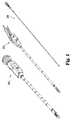
切除装置
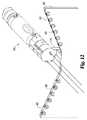
ここで図2〜図6を参照すると、切除装置100は、ハンドル部分110と、長尺な可撓性シャフト120によって結合される作用部分130とを含む。切除装置はガイドワイヤー(図示せず)上にわたって挿入されるようになっており、ガイドワイヤーは、ガイドワイヤーポート166で先端チップに入るとともに、吸引キャビティー131を通過した後、ガイドワイヤーポート165(図4)で再び装置内に入り、ガイドワイヤー出口ポート108でハンドルから抜け出る。また、切除装置は、従来の5〜6.5mm内視鏡(図示せず)とともに使用されるようになっており、該内視鏡は、内視鏡入口ポート103でハンドルに入って、シャフト120と作用部分130を形成する先端カプセルとの間の移行部分124で内視鏡出口ポート122から抜け出る。Ablation Device Referring now to FIGS. 2-6, the
ハンドル部分110は、従来のルアータイプの取付具を介して外部正圧源に接続されるようになっている吸入ポート102を含む。吸入ポート102は、先端チップの吸入ポート167へ装置100の長さにわたって延びる吸入管腔(図示せず)につながっており、これは、患者内に正圧を印加して例えば胃を膨張させるために使用される。正圧が吸入ポート167を通じて供給されているときに空気がガイドワイヤー管腔を通じて(すなわち、ポート165を介して)逆漏れしないように、ハンドル部分110のガイドワイヤーポート108には、使用していないときにガイドワイヤーポート108を塞ぐためのバルブまたはストッパが設けられてもよい。内視鏡管腔を通じた空気漏れは、内視鏡入口ポート103に可撓性シールを設けることにより減少されてもよい。 The
ハンドル部分110の吸引ポート101は、従来のルアータイプの取付具を介して外部真空源に接続されるようになっている。吸引ポート101は、ポート101での真空の印加が組織をキャビティー131内に引き込む役目を果たすように吸引管腔(図示せず)を介して吸引キャビティー131の床の吸引ポート135に接続される。 The
ハンドル110の注入ポート104は、注射針137に流体的に結合されており、切除前に注入液を捕捉された組織へ供給するために使用される。1つの使用形態では、3つの固定された注射針137を用いて、8ccの量の生理食塩水およびアドレナリン溶液が、粘膜層と筋肉層との間の胃組織中に注入される。注入流体が粘膜層を膨らませ、それにより、粘膜層と筋肉層との間の接合部が切断深さを規定する切除刃と一直線を成すように押される。注入流体が出血および漿膜の穿孔を防止する役目を果たしてもよい。注射針の先端は、流体が供給される組織の内側のポイントが切断が生じる場所にできる限り近くなるように切除刃の真下にくるように、寸法付けられることが好ましい。 The
注射針137は固定されてキャビティー131の底部から上方へ延びており、それにより、注射針は、吸引ポート135によって組織がキャビティーの床へ引き下ろされる際に組織に刺入する。注射針137は、吸引キャビティー131の対向する側壁141からほぼ等距離となるように吸引キャビティー131の長手方向中心線にほぼ沿って配置され、また、針137は、各針から等しい流量を確保するべくマニホールドに接続される。吸引ポート135は、キャビティー131の床に設けられて、中心に配置される注射針137の両側に配置されており、それにより、吸引力が印加されると、ほぼ等しい大きさの吸引力が注射針137の両側の組織に与えられ、そのため、注射針137の組織中への良好な刺入を確保するのに役立つ。注射針をキャビティー131の床の所定位置に固定するのではなく、注射針をキャビティーの床からあるいは側面から選択的に伸縮できるように構成することができる。 The
注射針137をキャビティー131の床から延ばして切除中に組織に係合させる1つの利点は、組織と注射針137との間の係合が切除作業中に組織を所定位置に固定するのに役立つという点である。言い換えると、係合された組織は、切断装置が組織を通過している間に所定の場所にとどまることができる高い能力を有する(すなわち、「一か所に集中すること」が回避される)。例えば吸引キャビティー137の床に対してテクスチャリングまたは他の表面特徴を加えるなど、床に対する組織の相対的な係合を高める他の形態が設けられてもよい。これに代えてあるいはこれに加えて、床面と同一平面である吸引ポート135を有するのではなく、前進する切断装置の方向へ向けて吸引ポートが傾けられてもよい。 One advantage of extending the
切除後、キャビティー131内に捕捉された組織は、ワイヤーまたは刃などの適切な組織カッタによって切除されるようになっている。切除装置が時期尚早に作動されないようにするため、組織カッタの作動を防止するべくロックアウト機構(図示せず)が設けられてもよい。ロックアウト機構は、流体が注入されると直ぐにあるいは装置が注入ポートに結合されると直ぐに自動的に解放されるようになっていてもよい。 After excision, the tissue captured in the
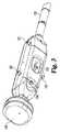
図示の実施形態では、刃132が、吸引キャビティー131の対向する側壁141にある案内スロット134内に配置される。案内スロット134は、キャビティー131の長手方向の長さにわたって比較的均一な切除深さを与えるように吸引キャビティー131の床と平行に延びている。この場合、言うまでもなく、図5および図6に示されるように、「長さ」は軸線Lを指し、「高さ」および「深さ」は軸線Hを指し、また、「幅」は軸線Wを指す。均一の切除深さを与えることは、組織の表面層だけが切除されるようにするために有益である。 In the illustrated embodiment, the
しかしながら、出願人は、吸引キャビティー131の幅が該キャビティーの長手方向の長さにわたって均一である必要がないこと、および、吸引の幅に変化を与えると多くの用途において特に有利となり得ることを見出した。例えば、図示の実施形態において、キャビティー131は、その基端140よりもその先端150の方が実質的に幅広く、先端側へ進むにつれて幅が徐々に増大するようになっている。キャビティー131の幅が先端側へ広がっているため、切除によってもたらされる露出組織の幅も同様に先端側へ向かって広がっている。 However, Applicants believe that the width of the
先端側へ広げられる露出組織部分の形成は多くの有用な用途を有することができ、また、出願人は、この形状が胃食道接合部(GEJ)に近いあるいは隣接する胃組織を切除する際に特に有益となることを見出した。これは、GEJから胃へ進むにつれて胃の容積が拡大し、したがって、GEJから特定の距離にある胃組織の有効表面積がGFJからの距離に伴って増大する(すなわち、逆漏斗と同様)からである。 The formation of an exposed tissue portion that is spread distally can have many useful applications, and applicants can use this shape when resecting gastric tissue close to or adjacent to the gastroesophageal junction (GEJ). I found it particularly useful. This is because the volume of the stomach expands as it goes from the GEJ to the stomach, and thus the effective surface area of stomach tissue at a certain distance from the GEJ increases with distance from the GFJ (ie, similar to a reverse funnel). is there.
また、キャビティー131の基端140は、より狭い幅を有することに加え、肩部分142の存在に起因して先端150とは異なっている。図5に示されるように、肩部分142は、基端140に隣接する隆起したテーパ部分であり、シャフト120への移行を滑らかにする役目を果たすとともに、余分な組織がキャビティー131の先端150へ摺動するあるいはさもなければ引き込まれることを制限する役目も果たす。吸引キャビティーの基端側に向かって狭くなる幅と基端の肩部分142との組合せは、装置が基端側のGEJの近傍の組織を切除するために使用される際に穿孔の危険を減らすための有効な方法となり得る。 Also, the
そのような穿孔の危険を更に減らすために、切除装置100の作用部分130には、装置100の正確な配置を確保するようになっている視覚マーキングが設けられてもよい。例えば、レーザエッチングされた距離マーキング138が作用部分130の側面に沿って設けられてもよく、また、生体構造の特定の場所に位置決めされるべき作用部分130上の所望の場所を視覚的に特定するために、色分けされた位置表示ステッカ172、170が作用部分の側面に貼り付けられてもよい。例えば、内視鏡を用いたGEJの視覚評価に基づいて、オペレータは、基端側肩部分142が配置されるべき場所を決定してもよく、また、その後に、肩部分142が所望の位置にあるときにどのくらいの量の作用部分130を胃の内側で見ることができるのかを決定してもよい。その後、表示された場所の両側の作用部分130に異なる色のステッカ172、170が配置されてもよい。その後、オペレータは、胃の内側の内視鏡でステッカが見えるようになるのを待つことにより、肩部分142が所望の位置に配置される時期を決定することができる。 To further reduce the risk of such perforations, the working
切除装置200には、アクチュエータ107および106がそれぞれ作動すると個別に拡張できるワイヤー160a、160bが更に設けられる。ワイヤー160a、160bは、それらの拡張されない形態(図4)では、キャビティー131の側面に沿って延びる凹部内に配置される。この位置において、ワイヤー160a、160bの外面は、装置の隣接する外面と略同一平面でありあるいは装置の隣接する外面よりも下側に奥まって配置され、それにより、装置100のほぼ滑らかな外面輪郭が保たれる。 The
ワイヤー160a、160bは、それらの先端165が圧着されあるいはさもなければキャビティーの先端150の近傍の位置に相対的に固定されるとともに、それらの基端がハンドルのアクチェータ107、106に結合される。ワイヤー160a、160bがニチノールなどの形状記憶材料および/または超弾性材料から形成されてもよく、それにより、アクチュエータ107を先端側に摺動させると、更なるワイヤーがチャンネルの基端部に入り込んで、図6に示されるようにワイヤー160aが径方向外側に弓形に曲げられる。この場合、弓形のワイヤー160a、160bは、水平から鋭角(例えば、約45°)を成す面内にほぼ配置される。 The wires 160a, 160b have their
図6の拡張形態では、ワイヤーの基端部分161がキャビティー131の基端近傍にあり、ワイヤーの先端部分165がキャビティー131の先端150近傍にあり、また、ワイヤーの中央部分163は、拡張されたワイヤーの形状および作動の程度によって決まる量だけ装置100の外面から離間される。例えば、拡張されたワイヤーが半円の形態を成した場合、中央部分163は、部分165と部分161との間の距離の約1/2または吸引キャビティー131の長さの約1/2に対応する1半径分だけ外面から離間される。様々な異なる拡張ワイヤー形状および形態が使用されてもよい。 In the expanded configuration of FIG. 6, the
非拡張位置(図4)から拡張位置(図6)へのワイヤー160a、160bの動きは、例えばワイヤーをその引込み位置に維持するために加えられる張力を解放することによってあるいはワイヤーを外側へ移行させるための圧縮を加えることによって機械的に達成される。また、動きは、例えばワイヤーに電流を印加することによって電気的に達成されてもよい。 Movement of the wires 160a, 160b from the non-expanded position (FIG. 4) to the expanded position (FIG. 6), for example, by releasing the tension applied to maintain the wire in its retracted position, or moving the wire outward. It is achieved mechanically by applying compression for. The movement may also be achieved electrically, for example by applying a current to the wire.
一般に、ワイヤーは多くの異なる方法で使用されてもよい。例えば、ワイヤーを組織と接触させた後に切除装置100をその長手方向軸線周りに回転させることによりおよび/または装置100を基端側または先端側に移動させることにより、拡張されたワイヤーのうちの1つ以上を組織マニピュレータとして使用することができる。他の用法において、ワイヤーは、吸引キャビティー131に対する吸引力の印加に伴って拡張され、望ましくない組織が吸引キャビティー131内に捕捉されるのを防止する役目を果たす。更なる他の形態では、拡張されたワイヤーが吸引トラフの両側に圧力を印加して(すなわち、トラフを後方に押し戻して)、それにより、吸引トラフと一直線を成す組織だけに吸引力の影響を及ぼすことができるようにする。 In general, the wire may be used in many different ways. For example, one of the expanded wires can be obtained by rotating the
切除装置100の他の態様は、吸引キャビティー115の床に上昇可能なプラットフォーム136を設ける。図6に示されるように、プラットフォーム136は、キャビティーの中心の中心切欠内に設けられ、注射針137の両側に沿って延びている。プラットフォーム136の下面は、ハンドル上のアクチュエータ105を摺動させることにより作動されるワイヤー(図示せず)に接続される。アクチュエータ105を先端側に押すことにより、プラットフォームワイヤーが押し上げられ、したがって、プラットフォーム136がキャビティーの床内のその位置から引き上げられる。これは、特に組織が固着するようになる場合または組織の除去が困難になる場合に、切断組織をキャビティーから除去するのを助けるために使用されてもよい。 Another aspect of the
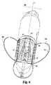
縫合装置
ここで、図7〜図11を参照すると、縫合装置200は、切除装置100と同様に構成され、210ハンドル部分を先端作用部230と接続する長尺シャフト220を含む。縫合装置200は、ハンドルの入口ポート(図示せず)から延びるガイドワイヤー管腔を介した標準的なガイドワイヤー上にわたって挿入されるようになっており、ガイドワイヤーは、穴265を介して吸引キャビティーを貫通し、最終的に先端チップの出口穴266から抜け出る。内視鏡は、ハンドル210の入口ポート201を介して挿入することができ、移行部分224の出口穴222を介して装置200から抜け出る。Suture Device Referring now to FIGS. 7-11, the
作用部230は、側部に配置される吸引キャビティー231と、吸引キャビティー内に捕捉された組織に対して横方向の縫合を施すようになっている針232の配列とを含む。組織は、ハンドル部分の吸引ポート(図示せず)まで延びる管腔275を介して真空がポート221に印加されるときに捕捉される。1つの考えられる用途において、縫合装置200は、標的の胃組織の漿膜の外部にある組織を縫合するのを回避しつつ、それが十分な太さの縫合糸を胃組織を貫通して施すように形成され、また、長さが30mmで幅が8mmの吸引キャビティーの選択は、適切な量の胃組織の捕捉を容易にできる。 The
作用部230は、一対の位置合わせピンを介して位置合わせ状態に維持される3つのカプセル部分240、241、242から成る。より具体的には、位置合わせピン237が3つの全てのカプセル部分の位置合わせ管腔274を貫通して延び、また、対応する位置合わせピン(図示せず)が管腔273を貫通して延びる。 The
3つのカプセル部分は、ハンドルに取り付けられるテンションコントローラ208によって維持される圧縮力の印加によって互いに保持される。より具体的には、テンションコード(図示せず)の一端が先端カプセル部分242に固定され、また、テンションコードは、中間カプセル部分241および基端カプセル部分240のテンション管腔270を貫通して基端側へ延びて、ハンドル210のテンションコントローラ208へ至る。テンション管腔270は、テンションコード上にわたって設けられかつ隣接するカプセル部分のそれぞれの対間に配置される圧縮スプリング(図示せず)と係合する凹状リップを伴って形成される。隣接するカプセル部分間に圧縮スプリングが存在することにより、圧縮力が十分に解放されると、カプセル部分が広がって離れるように付勢される(図8)。 The three capsule parts are held together by the application of a compressive force maintained by a
テンションコントローラ208は、細かいレベルの張力調整を行ない、それにより、シャフトの継ぎ目を補償するとともに、張力の急速なあるいは緊急の解放を行なって3つのカプセル部分を広げて離すようになっている。例えば、テンションコントローラ208は、外部フレーム212、および、例えばねじ付きロッドを回転させることによりフレーム212内のその位置が細かい調整を受けるテンションワイヤーマウント214の形態を成してもよい。このとき、外部フレーム212は、ハンドルの所定の位置に急速解放形態で取り付けられてもよい。 The
張力の急速解放を行なうことができる能力は、カプセル部分が広がり離される時点で針が最も外側の部品となるように装置内に配置されることを特に考慮すると、安全上の大きな利点である。例えば、縫合装置が縫合サイクルの途中にあった状態で緊急事態が生じる場合には、針が依然として組織に係合し、縫合装置が効果的に患者に縫い込まれる。針を急速に解放する方法がなければ、医師は、装置を除去できる前に縫合サイクルを完了させる必要がある。急速解放を行なうことができる能力は新たな選択肢を与える。この場合、置き去りにされたものを回収するためのその後の処置に患者が耐えることの方が緊急事態の差し迫った危険を担うよりも良い場合があるという理解の下で、緊急事態が生じれば、医師は、どこであろうとも、張力の急速解放を行なって、縫合針を放棄することができる。 The ability to provide rapid release of tension is a significant safety advantage, especially considering that the needle is placed in the device so that it becomes the outermost part when the capsule portion is spread and separated. For example, if an emergency occurs with the suturing device in the middle of a suturing cycle, the needle still engages the tissue and the suturing device is effectively sewn into the patient. Without a way to quickly release the needle, the physician needs to complete the suture cycle before the device can be removed. The ability to perform rapid release gives new options. In this case, if an emergency occurs, with the understanding that it may be better for the patient to withstand subsequent actions to recover what has been left behind, rather than taking the immediate danger of the emergency. The doctor can give up the suture needle anytime, making a quick release of tension.
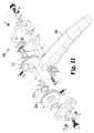
ここで、針の作動に戻ると、各針232は、円形であり、その内面233に3つの切欠を有する。この場合、各切欠は180°離間される。図8に示されるように、切欠234は先端の近傍であり、切欠235は後端の近傍であり、第3の切欠(図示せず)は針のほぼ中央部分にある。また、縫合糸(図示せず)は、各針に対してその中央部分の近傍で結合されるのが好ましい。その場合、各針からの糸の自由端は、先端チップの縫合糸入口穴を介してアクセスされる針自体の縫合糸戻し管腔272または271を通じて戻される。 Here, returning to the actuation of the needle, each
針232およびそれらの関連する駆動シャトル236は、カプセル部分のチャンネル253、263、262内に取り付けられる。針232は他の円形チャンネル263、262内に配置され、駆動シャトル236は下側チャンネル253内の針232の内側に配置される。駆動シャトル236は、針を駆動する目的で内部切欠(例えば234、235)のうちの1つと係合する一方向スプリングラッチ(図示せず)を含み、また、シャトル236は、適切な位置合わせを確保して支持する目的で針232の側面の周囲で延びる内部チャンネルを有する。
シャトルは、管腔278および279のそれぞれを先端側へ貫通して延びる第1および第2の牽引ワイヤー(図示せず)に結合される。シャトルは、前方牽引ワイヤー(279)または後方牽引ワイヤー(278)のいずれにより大きな張力が印加されているかに基づいて半球状のチャンネル253内で一端251から他端252へ前後に円弧を描く上側側壁250の存在により制約される。張力差がなければ(すなわち、ワイヤーが釣り合っていれば)、シャトル236は動かない。 The shuttle is coupled to first and second puller wires (not shown) that extend distally through
ハンドル部分210は、トリガ202の位置がシャトルの位置を決定するように、より具体的には、トリガ202を圧搾することによりシャトルが端部252へ向けて前方へ移動しかつトリガを解放することによりシャトルが端部251へ戻るように構成される。これは、牽引ワイヤーを相対する方向に巻き付けてそれらを同じ方向に回転させられるハブ310、320に取り付けることにより達成されてもよい。この場合には、異なる牽引ワイヤーが反対に巻き付けられるため、ハブ310、320を一方向に回転させると一方の牽引ワイヤーが巻き付き/ピンと張る一方で、他方の牽引ワイヤーが繰り出し/緩む。 More specifically, the
図11に示されるように、ハブ310、320は、一般に同じ方向に回転するが、常に強固に結合されない。むしろ、牽引ワイヤーが常にある水準より下の張力を受けるようにする逆回転付勢を与えるために、トーションスプリング315がハブ310、320間に介挿される。牽引ワイヤーを一定の張力に維持すると、例えばシャフトの屈曲に起因して発現し得るあらゆる不必要な緩みが除かれ、全体の動きが滑らかになる。 As shown in FIG. 11, the
トリガ102は、牽引ワイヤーに作用する張力を解放できる急速解放能力を与えるために、L形状のスロット内に配置されるスライドプレートピン204によりハンドル210に回動可能に取り付けられる。通常の動作中、ピン204は基端側にあり、牽引ワイヤーが張力を受ける。張力状態を維持するために、ピン204は、一般に、L形状スロットの下方へ延びる部分へ下向きに滑り込む。例えば緊急事態の場合に張力を解放するため、ピン204が上方に上げられ、また、ピンは、角部を越えると、牽引ワイヤーの張力を解放するために基端側に自由に摺動できる。 The
針232の内部切欠(235、234)は複数の目的を果たす。駆動シャトル236のための係合ポイントとしての役目を果たすことに加え、針の後端の内部切欠235が全ストロークの終了部分となるポイント(図9の276)でキャビティー262内にスプリングバー238が設けられる。スプリングバー238は、後端切欠235を捕捉して、それをこの位置に保持する。これは、針が吸引キャビティーを完全に越えるサイクル中の唯一のポイントであるため、重要な位置である。 The internal notches (235, 234) of the
針をこの位置に固定する更なる手段として、ハンドル210のスライダ205の作動により確認ワイヤー206が管腔277を貫通して延ばされる。確認ワイヤー206が所定位置にある状態では、セキュリティーが非常に高いとともに、不測の針移動に抗する。また、常に所定位置にあるスプリングバー238とは異なり、確認ワイヤー206は、可撓性である必要はなく、所定位置にあるときに針が所定の位置で効果的にロックされるように寸法付けることができる。したがって、確認ワイヤー206はロックバーとしての役目を果たすことができる。 As a further means of securing the needle in this position, actuation of
結び目形成/縫合管理
縫合糸が施されると、縫合糸が患者の外側で集められてまとめられ、それにより、特定の対象処置に応じて適切な縫合糸が互いに結び付けられる。実際には互いに結び付けるのではなく、一般に結び目形成装置300が使用される。当該技術分野において知られるように、結び目形成装置は、所望の縫合ワイヤーに対してそれらをきつく引張りつつクリンプまたはスリーブまたは同様の機械的な留め具を適用する。結び目形成具300は、10mm内視鏡と一緒に使用されてもよい結び目形成装置の一例である。Knotting / Suture Management Once sutures are applied, the sutures are collected and grouped outside the patient, thereby tying the appropriate sutures together for a particular target procedure. In practice, the
縫合編成プロセスを容易にするため、縫合管理補助具400が設けられてもよい。縫合管理補助具は、縫合装置200の先端作用部を受けるための中心マウント410と、両側に広げられる複数の縫合糸ホルダ420とを有する。図示のように、縫合糸ホルダ420は上方へ延びる形態で形成されており、そのため、外側へ向かって延びつつ中心に配置されるものが誤って外れる機会を減らす役目を果たす。 A
エアウェイ咬合阻止器
図13および図14は、本明細書中に記載される縫合・切除処置中に使用するための咬合阻止器を示している。咬合阻止器は、別個に挿入されるエアウェイと共に用いるようになっている。咬合阻止器500は、患者の歯間に配置されて器具が口腔へアクセスできるようにする主管腔520を含む。咬合阻止器500は、主管腔505の両側に一対の側孔540、550と、ヘッドストラップを取り付けるためのTコネクタとを含む。エアウェイマウント560が側孔のうちの一方540に配置される。エアウェイマウントは咬合阻止器と一体に成形される。エアウェイマウント560の目的は、処置中に陽性気道を効果的に与えるべくエアウェイが側孔のうちの一方540から口腔内へ先端側に延びるようにエアウェイを咬合阻止器に固定することである。Airway Occlusal Stopper FIGS. 13 and 14 illustrate an occlusal arrester for use during the suturing and ablation procedures described herein. The bite block is intended for use with a separately inserted airway. The
エアウェイは、陽性気道を維持するのに十分な直径、長さ、および、剛性を有する可撓性チューブであってもよい。1つの形態において、エアウェイマウントは、経鼻的に使用されるようになっている市販のエアウェイである鼻咽頭エアウェイ(NPA)を受け入れるように形成される。鼻咽頭エアウェイは、広がったあるいはトランペット状の端部を有する長尺な可撓性チューブの形状を成す。エアウェイの従来の使用では、チューブが患者の鼻道内に挿入され、その場合、広がった端部が、鼻孔に当接してNPAが鼻腔内に入らないようにする役目を果たす。驚くべきことに、出願人は、NPAが口咽頭エアウェイとして機能するように口腔内に挿入されるときにうまく機能することを見出した。 The airway may be a flexible tube with a diameter, length, and stiffness sufficient to maintain a positive airway. In one form, the airway mount is configured to receive a nasopharyngeal airway (NPA), a commercially available airway that is adapted for nasal use. The nasopharyngeal airway is in the form of an elongate flexible tube with a widened or trumpeted end. In conventional use of airways, the tube is inserted into the patient's nasal passage, where the widened end serves to abut the nostril and prevent the NPA from entering the nasal cavity. Surprisingly, Applicants have found that NPA works well when inserted into the oral cavity to function as an oropharyngeal airway.
エアウェイマウント560は、特に、標準的なNPAと摩擦嵌合を形成してNPAが患者によって押し出される機会を減らすように設計されて構成される。エアウェイマウント560は、9〜15mm、5〜12mm、5〜15mm、6〜14mm、7〜13mm、8〜12mm、または、8〜11mmの範囲、または、約9mmの内径を有する円形穴である。 The
咬合阻止器に関して、説明してきたものは咬合阻止器とエアウェイとの組合せである。この場合、咬合阻止器は、口腔内で先端が終端する主管腔を形成する本体と、一対の側部開口とを備え、エアウェイは、側部開口のうちの一方に取り付けられるとともに、主管腔の先端縁を実質的に通り過ぎて患者の口腔内へ延びる。エアウェイは、例えば鼻咽頭エアウェイのように、広がった基端を有する長尺な可撓性チューブを備えてもよい。エアウェイは、スナップ嵌合または摩擦嵌合の取付け構成によって咬合阻止器に固定されてもよい。 With respect to the bite blocker, what has been described is a combination bite blocker and airway. In this case, the occlusion blocker includes a main body that forms a main lumen whose tip ends in the oral cavity, and a pair of side openings, and the airway is attached to one of the side openings, Extends substantially past the leading edge into the patient's mouth. The airway may comprise an elongate flexible tube with a widened proximal end, such as a nasopharyngeal airway. The airway may be secured to the bite arrester by a snap fit or friction fit mounting configuration.
また、説明してきたものは、患者の上歯と下歯の間にそれぞれ配置されるようになっている上側外面および下側外面を形成するとともに、器具がアクセスできるようにするための作業管腔を形成する主咬合阻止器本体を備えるシステムであり、この場合、咬合阻止器は、使用中に患者の口の外側に配置されるようになっている外面を含み、外面が一対の側部開口を形成し、また、システムは、側部開口のうちの一方に配置されかつ口咽頭エアウェイとして機能するように患者の口腔内へ先端側に延びる鼻咽頭エアウェイを備える。鼻咽頭エアウェイが咬合阻止器に固定されてもよい。鼻咽頭エアウェイは、ストラップまたはマウントを介して咬合阻止器に固定されてもよい。鼻咽頭エアウェイは、前面のそれぞれの側部開口内に配置されるマウントを介して咬合阻止器に固定されてもよい。マウントは、側部開口の内面から延びかつ鼻咽頭エアウェイと係合する湾曲面を与える部分を備えてもよい。マウントは、少なくとも2つの異なる位置で側部開口の内面と接触してもよい。マウントの実質的部分が咬合阻止器と一体に形成される。 Also, what has been described is a working lumen for forming an upper outer surface and a lower outer surface that are adapted to be placed between a patient's upper and lower teeth, respectively, and for providing access to the instrument. A system comprising a main occlusal arrester body, wherein the occlusal arrester includes an outer surface adapted to be placed outside the patient's mouth during use, the outer surface being a pair of side openings. And the system includes a nasopharyngeal airway disposed distally into one of the side openings and extending distally into the patient's oral cavity to function as an oropharyngeal airway. A nasopharyngeal airway may be secured to the occlusion arrester. The nasopharyngeal airway may be secured to the occlusion arrester via a strap or mount. The nasopharyngeal airway may be secured to the occlusal arrester via a mount disposed within each side opening of the anterior surface. The mount may include a portion that provides a curved surface that extends from the inner surface of the side opening and engages the nasopharyngeal airway. The mount may contact the inner surface of the side opening at at least two different locations. A substantial portion of the mount is integrally formed with the occlusal arrester.
また、説明されるものは、鼻咽頭エアウェイと共に使用するための咬合阻止器であって、患者の上歯と下歯の間にそれぞれ配置されるようになっている上側外面および下側外面を形成するとともに、器具がアクセスできるようにするための作業管腔を形成する主咬合阻止器本体を備え、咬合阻止器が、使用中に患者の口の外側に配置されるようになっている外面を含み、外面が一対の側部開口を形成し、鼻咽頭エアウェイが口咽頭エアウェイとして機能するように側部開口のうちの一方に鼻咽頭エアウェイを保持するように構成されるマウントを備える、咬合阻止器である。マウントは咬合阻止器と一体に成形されてもよい。マウントは、側部開口のうちの一方の側部開口内に配置されるとともに、少なくとも2つの別個の位置で側部開口の内面と接触してもよい。マウントは、摩擦嵌合またはスナップ嵌合の構成によって鼻咽頭エアウェイの広がった端部と結合するように構成されてもよい。マウントは、鼻咽頭エアウェイの基端部の曲率およびテーパに対応して湾曲して先細りした対向する内面を形成してもよい。 Also described is an occlusal deterrent for use with a nasopharyngeal airway that forms an upper outer surface and a lower outer surface adapted to be placed between the patient's upper and lower teeth, respectively. And a main occlusal arrester body defining a working lumen for access by the instrument, wherein the occlusal arrester has an outer surface adapted to be placed outside the patient's mouth during use. Occlusion prevention, comprising a mount configured to hold a nasopharyngeal airway on one of the side openings so that the outer surface forms a pair of side openings and the nasopharyngeal airway functions as an oropharyngeal airway It is a vessel. The mount may be molded integrally with the bite blocker. The mount may be disposed within one of the side openings and may contact the inner surface of the side opening at at least two distinct locations. The mount may be configured to couple with the widened end of the nasopharyngeal airway by a friction fit or snap fit configuration. The mount may form an opposing inner surface that is curved and tapered to correspond to the curvature and taper of the proximal end of the nasopharyngeal airway.
また、説明されるものは、横方向円形針を利用する新規な縫合装置であり、この場合、針は、針を前進させるために駆動シャトルによって係合されかつ各ストロークの終了時に付勢プランジャによって係合される二重目的の切欠を有する。これらの切欠は針の内面上にあってもよい。完全な回転ごとに3つのストロークを得るために3つの切欠が存在してもよい。縫合装置は、針をそれらの初期位置から移動させることができる前に引き込まれなければならない確認ロッドを含んでもよい。駆動シャトルが牽引ワイヤーによって作動されてもよい。牽引ワイヤーがハンドルの回転ハブに取り付けられてもよく、その場合、ハブは圧搾トリガによって駆動される。 Also described is a novel suturing device that utilizes a transverse circular needle, where the needle is engaged by a drive shuttle to advance the needle and by a biasing plunger at the end of each stroke. Has a dual purpose notch to be engaged. These notches may be on the inner surface of the needle. There may be three notches to obtain three strokes per full rotation. The suturing device may include a confirmation rod that must be retracted before the needle can be moved from their initial position. The drive shuttle may be actuated by a puller wire. A puller wire may be attached to the rotating hub of the handle, in which case the hub is driven by a squeeze trigger.
説明してきたものは、望ましくない組織が吸引キャビティー内に捕捉されないようにする機構を有する新規な切除装置を含む。機構は、吸引キャビティーの両側に配置される複数の拡張可能な部材を含んでもよい。拡張可能な部材は、それらの非拡張状態時には凹部内に収容されてもよい。拡張可能な部材がワイヤーであってもよく、また、ワイヤーは、一端が固定されて、圧縮力を受けて外側に拡張してもよい。 What has been described includes a novel ablation device having a mechanism that prevents unwanted tissue from being trapped within the aspiration cavity. The mechanism may include a plurality of expandable members disposed on opposite sides of the suction cavity. The expandable members may be housed within the recess when in their unexpanded state. The expandable member may be a wire, and the wire may be fixed to one end and expanded outward under a compressive force.
また、説明してきたものは、切除組織の除去を助けるために上昇可能なプラットフォームを吸引キャビティー内に有する新規な切除装置である。プラットフォームは、持ち上げられる前にあっては床内に埋め込まれてもよい。プラットフォームは、複数の押出しワイヤーによって持ち上げられてもよい。プラットフォームは、吸引穴および/または注射針を吸引キャビティーの床に受け入れるために複数の開口を有してもよい。 What has been described is also a novel ablation device having a platform that can be raised in the aspiration cavity to assist in the removal of ablated tissue. The platform may be embedded in the floor before it is lifted. The platform may be lifted by a plurality of extrusion wires. The platform may have a plurality of openings for receiving suction holes and / or needles in the floor of the suction cavity.
また、説明してきたものは、組織の時期尚早の切除を防止するためのロックアウト機構を有する新規な切除装置である。ロックアウト機構は、捕捉された組織に注入液を供給する前に切除することを防止するために使用されてもよい。ロックアウトは、注射器がハンドルマウントに取り付けられるときに、自動的に解放されるように構成されてもよい。 What has been described is a novel ablation device having a lockout mechanism to prevent premature excision of tissue. The lockout mechanism may be used to prevent ablation prior to delivering the infusate to the captured tissue. The lockout may be configured to be automatically released when the syringe is attached to the handle mount.
また、説明してきたものは、キャビティーの床から上方へ延ばすことができかつ注入後に床内へ引き込ませることができる注射針を有する新規な切除装置である。 Also described is a novel ablation device having an injection needle that can extend upward from the floor of the cavity and can be retracted into the floor after injection.
本明細書中に記載される新規な切除装置は、胃、食道、結腸、または、胃腸管の他の部分内の組織の表面層を切除するために使用されてもよい。切除装置は、単独で使用されてもよく、または、縫合装置、例えば本明細書中に記載される縫合装置のうちのいずれかと組み合わせて使用されてもよい。 The novel ablation devices described herein may be used to ablate surface layers of tissue in the stomach, esophagus, colon, or other parts of the gastrointestinal tract. The ablation device may be used alone or in combination with a suturing device, eg, any of the suturing devices described herein.
また、説明されるものは、横方向円形針を利用する新規な縫合装置であり、この場合、針は、針を前進させるために駆動シャトルによって係合されかつ各ストロークの終了時に付勢プランジャによって係合される二重目的の切欠を有する。これらの切欠は針の内面上にあってもよい。完全な回転ごとに3つのストロークを得るために3つの切欠が存在してもよい。縫合装置は、針をそれらの初期位置から移動させることができる前に引き込まれなければならない確認ロッドを含んでもよい。駆動シャトルが牽引ワイヤーによって作動されてもよい。牽引ワイヤーがハンドルの回転ハブに取り付けられてもよく、その場合、ハブは圧搾トリガによって駆動される。 Also described is a novel suturing device that utilizes a transverse circular needle, where the needle is engaged by a drive shuttle to advance the needle and by a biasing plunger at the end of each stroke. Has a dual purpose notch to be engaged. These notches may be on the inner surface of the needle. There may be three notches to obtain three strokes per full rotation. The suturing device may include a confirmation rod that must be retracted before the needle can be moved from their initial position. The drive shuttle may be actuated by a puller wire. A puller wire may be attached to the rotating hub of the handle, in which case the hub is driven by a squeeze trigger.
また、説明されるものは、横方向円形針が吸引キャビティーにわたってシャトルにより多段階で駆動される新規な縫合装置であり、シャトルは、圧搾トリガにより駆動されるハブに取り付けられる牽引ワイヤーによって作動される。圧搾トリガがハブを一方向に回転させてもよく、その場合、ハブは、各ストロークの終了時にスプリングの力を受けて跳ね戻るようになっており、複数のストロークが針の完全な回転を形成する。ハンドルは、針の作動状態を示すためのカウンタを含んでもよい。縫合装置は、各ストロークの終了時に針の切欠と係合するロックスプリング/ロックロッドを含んでもよい。圧搾トリガは、それをハブから選択的に離脱させて牽引ワイヤーに作用する張力を解放できるように構成されてもよい。 Also described is a novel suturing device in which a transverse circular needle is driven in multiple stages by a shuttle across a suction cavity, which is actuated by a puller wire attached to a hub driven by a squeeze trigger. The A squeeze trigger may cause the hub to rotate in one direction, in which case the hub will spring back at the end of each stroke, and multiple strokes form a complete rotation of the needle To do. The handle may include a counter for indicating the operating state of the needle. The suturing device may include a lock spring / lock rod that engages the notch of the needle at the end of each stroke. The squeeze trigger may be configured so that it can be selectively removed from the hub to release the tension acting on the puller wire.
また、説明されるものは、横方向円形針が多部品カプセルの隣り合う部分間に形成されるチャンネル内に収容され、針を解放するためにカプセル部分を分離できる縫合装置である。カプセル部分が圧縮力によって互いに保持されてもよく、圧縮力がハンドルで解放されてもよい。圧縮力はタイロッドによって印加されてもよい。ロッドがねじ付けられ、ロッドを回してねじを緩めることよって圧縮力が解放されてもよい。 Also described is a suturing device in which a transverse circular needle is housed in a channel formed between adjacent portions of a multi-part capsule and the capsule portions can be separated to release the needle. The capsule portions may be held together by a compressive force, and the compressive force may be released with a handle. The compressive force may be applied by a tie rod. The rod may be screwed and the compressive force may be released by turning the rod to loosen the screw.
また、説明されるものは、それぞれが関連する駆動シャトルを伴う複数の横方向円形針を有する縫合装置であり、それぞれの針および駆動シャトルはカプセル部分の異なる対間に収容され、また、カプセル部分は長手方向に離間されるように構成される。 Also described is a suturing device having a plurality of transverse circular needles, each with an associated drive shuttle, each needle and drive shuttle being housed between different pairs of capsule portions, and capsule portions Are configured to be spaced apart in the longitudinal direction.
また、説明されるものは、それぞれが共通の保持材を通じて挿入されることなく使用されるようになっている単独型の切除装置および単独型の縫合装置を備える胃形成術およびGERD処置を行なうための新規なシステムである。一方または両方の装置がガイドワイヤー上にわたって挿入されるようになっていてもよい。それぞれの装置は、ハンドル部分と、長尺な本体と、吸引キャビティーを有する先端作用部とを有してもよい。各装置は、それらのそれぞれの長尺な本体に内視鏡管腔を有してもよい。内視鏡管腔は、内視鏡がハンドル内に入って吸引キャビティーの基端側から抜け出るように形成されてもよい。主長尺本体と作用部との間の可撓性の移行部分によって各装置に内視鏡出口穴が設けられてもよい。可撓性の移行部分は、主長尺本体および/または先端作用部とは異なる(より可撓性のある)材料から成ってもよい。 Also, what is described is for performing gastroplasty and GERD procedures with a single resection device and a single suturing device, each of which is intended to be used without being inserted through a common retainer. This is a new system. One or both devices may be inserted over the guide wire. Each device may have a handle portion, an elongated body, and a tip effector having a suction cavity. Each device may have an endoscope lumen in their respective elongate body. The endoscope lumen may be formed such that the endoscope enters the handle and exits from the proximal side of the suction cavity. An endoscope exit hole may be provided in each device by a flexible transition between the main elongate body and the working portion. The flexible transition portion may be made of a different (more flexible) material than the main elongate body and / or the tip effector.
Claims (33)
Translated fromJapanese長尺な第1の可撓性シャフトを介して第1の作用部に接続される第1のハンドル部分を備える切除装置であり、前記第1の作用部が、組織を捕捉するために側部に配置される長尺な第1の吸引キャビティーと、前記第1の吸引キャビティー内に捕捉された組織の層を切除するために前記第1のハンドル部分の切除アクチュエータが作動すると前記第1の吸引キャビティーを横切るようになっている組織切除装置とを備える、前記切除装置と、
長尺な第2の可撓性シャフトを介して第2の作用部に接続される第2のハンドル部分を備える縫合装置であり、前記第2の作用部が、側部に配置される第2の吸引キャビティーと、前記第2の吸引キャビティー内に捕捉された組織に対して複数の横方向の縫合を施すように構成される複数の針とを備える、前記縫合装置と、
を備え、
前記第1の吸引キャビティーの少なくとも1つの寸法が前記第2の吸引キャビティーの対応する寸法と異なる、システム。A system for performing gastrointestinal procedures,
An ablation device comprising a first handle portion connected to a first working portion via an elongated first flexible shaft, wherein the first working portion is a side portion for capturing tissue An elongate first aspiration cavity disposed in the first aspiration cavity and actuation of an ablation actuator of the first handle portion to ablate a layer of tissue captured in the first aspiration cavity; A tissue resection device adapted to traverse the suction cavity of
A suturing device comprising a second handle portion connected to a second working portion via a long second flexible shaft, wherein the second working portion is arranged on a side portion. The suturing device comprising: a plurality of aspiration cavities; and a plurality of needles configured to perform a plurality of lateral sutures on tissue captured in the second aspiration cavity;
With
The system, wherein at least one dimension of the first suction cavity is different from a corresponding dimension of the second suction cavity.
長尺な可撓性シャフトを介して作用部に接続されるハンドル部分を備え、前記作用部が、組織を捕捉するために側部に配置される長尺な吸引キャビティーと、前記吸引キャビティー内に捕捉された組織の層を切除するために前記ハンドル部分の切除アクチュエータが作動すると前記吸引キャビティーを横切るようになっている組織切除装置とを備え、
前記作用部が、望ましくない組織を前記吸引キャビティー内に捕捉しないように前記ハンドル部分の拡張アクチュエータが作動すると前記吸引キャビティーの側面から拡張可能な第1および第2の部材を更に備える、切除装置。A resecting device for resecting tissue from the inside of an organ during a minimally invasive procedure,
A long suction cavity comprising a handle portion connected to the working part via a long flexible shaft, the working part being arranged on the side for capturing tissue; and the suction cavity A tissue ablation device adapted to traverse the aspiration cavity when an ablation actuator of the handle portion is actuated to ablate a layer of tissue captured therein;
The ablation further comprises first and second members that are expandable from the sides of the aspiration cavity when an expansion actuator of the handle portion is actuated so that the working portion does not trap undesired tissue in the aspiration cavity. apparatus.
長尺な可撓性シャフトを介して作用部に接続されるハンドル部分を備え、前記作用部が、側部に配置される吸引キャビティーと、前記第2の吸引キャビティー内に捕捉された組織に対して複数の横方向の縫合を施すように構成される複数の針とを備え、
前記針が、多部品カプセルの隣り合う部分間に形成されるチャンネル内に収容される、縫合装置。A suturing device for performing a transverse suture on a tissue,
A handle portion connected to the action portion via a long flexible shaft, wherein the action portion is disposed in a side portion of the suction cavity, and the tissue is captured in the second suction cavity. A plurality of needles configured to perform a plurality of lateral sutures with respect to
A suturing device wherein the needle is housed in a channel formed between adjacent portions of a multi-part capsule.
長尺な可撓性シャフトを介して作用部に接続されるハンドル部分を備え、前記作用部が、側部に配置される吸引キャビティーと、前記第2の吸引キャビティー内に捕捉された組織に対して複数の横方向の縫合を施すように構成される複数の針とを備え、
前記針が、該針の内面の切欠と係合する少なくとも1つの駆動シャトルにより略円形の経路内で駆動される湾曲針である、縫合装置。A suturing device for performing a transverse suture on a tissue,
A handle portion connected to the action portion via a long flexible shaft, wherein the action portion is disposed in a side portion of the suction cavity, and the tissue is captured in the second suction cavity. A plurality of needles configured to perform a plurality of lateral sutures with respect to
A suturing device wherein the needle is a curved needle that is driven in a generally circular path by at least one drive shuttle that engages a notch in the inner surface of the needle.
前記咬合阻止器が、使用中に患者の口の外側に配置されるようになっている外面を含み、前記外面が一対の側部開口を形成し、
前記側部開口のうちの一方に配置され、口咽頭エアウェイとして機能するように先端側が患者の口腔内へ延びる鼻咽頭エアウェイを備える、システム。A main occlusal arrester body forming an upper outer surface and a lower outer surface adapted to be respectively disposed between a patient's upper and lower teeth and forming a working lumen for access by the instrument;
The occlusal deterrent includes an outer surface adapted to be placed outside a patient's mouth during use, the outer surface forming a pair of side openings;
A system comprising a nasopharyngeal airway disposed at one of the side openings and extending distally into the patient's oral cavity to function as an oropharyngeal airway.
患者の上歯と下歯の間にそれぞれ配置されるようになっている上側外面および下側外面を形成するとともに、器具がアクセスするための作業管腔を形成する主咬合阻止器本体を備え、
前記咬合阻止器が、使用中に患者の口の外側に配置されるようになっている外面を含み、前記外面が一対の側部開口を形成し、
鼻咽頭エアウェイが口咽頭エアウェイとして機能するように前記側部開口のうちの一方に前記鼻咽頭エアウェイを保持するように構成されるマウントを備える、咬合阻止器。An occlusal arrester for use with a nasopharyngeal airway,
A main occlusal arrester body forming an upper outer surface and a lower outer surface adapted to be respectively disposed between a patient's upper and lower teeth and forming a working lumen for access by the instrument;
The occlusal deterrent includes an outer surface adapted to be placed outside a patient's mouth during use, the outer surface forming a pair of side openings;
An occlusion arrester comprising a mount configured to hold the nasopharyngeal airway in one of the side openings so that the nasopharyngeal airway functions as an oropharyngeal airway.
Applications Claiming Priority (5)
| Application Number | Priority Date | Filing Date | Title |
|---|---|---|---|
| US22008909P | 2009-06-24 | 2009-06-24 | |
| US61/220,089 | 2009-06-24 | ||
| US22154509P | 2009-06-29 | 2009-06-29 | |
| US61/221,545 | 2009-06-29 | ||
| PCT/US2010/039879WO2010151712A2 (en) | 2009-06-24 | 2010-06-24 | Systems and techniques for performing gastrointestinal procedures |
Publications (1)
| Publication Number | Publication Date |
|---|---|
| JP2012531271Atrue JP2012531271A (en) | 2012-12-10 |
Family
ID=43387131
Family Applications (1)
| Application Number | Title | Priority Date | Filing Date |
|---|---|---|---|
| JP2012517749APendingJP2012531271A (en) | 2009-06-24 | 2010-06-24 | Systems and techniques for performing gastrointestinal procedures |
Country Status (9)
| Country | Link |
|---|---|
| US (1) | US20120204865A1 (en) |
| EP (1) | EP2445424A4 (en) |
| JP (1) | JP2012531271A (en) |
| KR (1) | KR20130008505A (en) |
| AU (1) | AU2010266041A1 (en) |
| CA (1) | CA2766379A1 (en) |
| IL (1) | IL217119A0 (en) |
| SG (1) | SG177365A1 (en) |
| WO (1) | WO2010151712A2 (en) |
Cited By (2)
| Publication number | Priority date | Publication date | Assignee | Title |
|---|---|---|---|---|
| JP2021526948A (en)* | 2018-06-07 | 2021-10-11 | エンビジョン・エンドスコピー | Endoscopic suture device with circular needle |
| CN113598854A (en)* | 2021-08-05 | 2021-11-05 | 钱晓云 | Nasal septum suturing device |
Families Citing this family (14)
| Publication number | Priority date | Publication date | Assignee | Title |
|---|---|---|---|---|
| CA2786747C (en)* | 2010-01-13 | 2017-05-16 | Thomas Julius Borody | A mask for use with a patient undergoing a sedated endoscopic procedure |
| AU2013345295A1 (en)* | 2012-11-14 | 2015-05-21 | Divakara GOUDA | Ventilating bite block for use in endoscopy procedures |
| CN105228537A (en)* | 2013-03-11 | 2016-01-06 | 波士顿科学国际有限公司 | Device for excising and associated method of use |
| US20140276979A1 (en)* | 2013-03-15 | 2014-09-18 | Lsi Solutions, Inc. | Method and devices for securing bidirectional suture loops using coaxial mechanical fasteners |
| US10258319B2 (en) | 2015-05-18 | 2019-04-16 | Richard L. Arden | Airway assist device and method |
| US10010313B2 (en) | 2015-05-18 | 2018-07-03 | Richard L. Arden | Mandibular subluxation device and method |
| US10342526B2 (en) | 2015-07-01 | 2019-07-09 | Richard L. Arden | Airway assist device and method |
| US10299795B2 (en) | 2016-04-28 | 2019-05-28 | Mayo Foundation For Medical Education And Research | Devices and methods for esophageal lengthening and anastomosis formation |
| SG10201903589VA (en)* | 2016-06-01 | 2019-05-30 | Endomaster Pte Ltd | Endoscopy system components |
| US11737745B2 (en) | 2018-10-24 | 2023-08-29 | Mayo Foundation For Medical Education And Research | Medical devices and methods for body conduit lengthening and anastomosis formation |
| WO2020144693A1 (en)* | 2019-01-09 | 2020-07-16 | Nitinotes Ltd. | Tissue manipulation with an endoluminal gastroplasty device |
| WO2021171290A1 (en) | 2020-02-26 | 2021-09-02 | Nitinotes Ltd. | Suturing with an endoluminal gastroplasty device |
| EP4231947A4 (en) | 2020-10-23 | 2024-10-02 | Envision Endoscopy, Inc. | ENDOSCOPIC SUTURE STRAP |
| CN114343790B (en)* | 2021-12-27 | 2023-06-09 | 齐齐哈尔医学院 | Mammary tumor minimally invasive surgery cutter with bionic maggot mouth |
Citations (6)
| Publication number | Priority date | Publication date | Assignee | Title |
|---|---|---|---|---|
| JPH03162844A (en)* | 1989-08-25 | 1991-07-12 | Olympus Optical Co Ltd | Organism inspection tool |
| US5693011A (en)* | 1995-04-27 | 1997-12-02 | Surgical Dynamics, Inc. | Surgical suction cutting instrument |
| US6214009B1 (en)* | 1998-09-09 | 2001-04-10 | Xomed Surgical Products, Inc. | Rhinoplasty bur |
| US6443959B1 (en)* | 1999-02-16 | 2002-09-03 | Instruments Medicaux Gb Inc. | Surgical extractor |
| JP2005103268A (en)* | 2003-09-29 | 2005-04-21 | Ethicon Endo Surgery Inc | Endoscopic mucosal resection device and using method thereof |
| JP2007111516A (en)* | 2005-09-02 | 2007-05-10 | Ethicon Endo Surgery Inc | Method and apparatus for endoscopically performing gastric reduction surgery in one step |
Family Cites Families (19)
| Publication number | Priority date | Publication date | Assignee | Title |
|---|---|---|---|---|
| US4508533A (en)* | 1980-07-14 | 1985-04-02 | Daniel Abramson | Surgical drain |
| US4644951A (en)* | 1985-09-16 | 1987-02-24 | Concept, Inc. | Vacuum sleeve for a surgical appliance |
| US5190541A (en)* | 1990-10-17 | 1993-03-02 | Boston Scientific Corporation | Surgical instrument and method |
| US5104394A (en)* | 1990-11-05 | 1992-04-14 | Knoepfler Dennis J | Automatic stapler for laparoscopic procedure with selective cutter and suction irrigator |
| JPH05220157A (en)* | 1992-02-18 | 1993-08-31 | Olympus Optical Co Ltd | Excision device for medical treatment |
| DE4300064A1 (en)* | 1993-01-05 | 1994-07-07 | Wolf Gmbh Richard | Tissue punch |
| WO1995003843A1 (en)* | 1993-07-30 | 1995-02-09 | The Regents Of The University Of California | Endocardial infusion catheter |
| US5513634A (en)* | 1994-05-06 | 1996-05-07 | Chek-Med Systems, Inc. | Combination integral bite block airway and nasal cannula |
| US7338434B1 (en)* | 2002-08-21 | 2008-03-04 | Medtronic, Inc. | Method and system for organ positioning and stabilization |
| EP1261282B1 (en)* | 2000-03-03 | 2013-09-25 | C. R. Bard, Inc. | Endoscopic tissue apposition device with multiple suction ports |
| US7458940B2 (en)* | 2000-11-06 | 2008-12-02 | Suros Surgical Systems, Inc. | Biopsy apparatus |
| US6398795B1 (en)* | 2000-11-30 | 2002-06-04 | Scimed Life Systems, Inc. | Stapling and cutting in resectioning for full thickness resection devices |
| US7628780B2 (en)* | 2001-01-13 | 2009-12-08 | Medtronic, Inc. | Devices and methods for interstitial injection of biologic agents into tissue |
| US6997931B2 (en)* | 2001-02-02 | 2006-02-14 | Lsi Solutions, Inc. | System for endoscopic suturing |
| US6733512B2 (en)* | 2002-03-07 | 2004-05-11 | Mcghan Jim J. | Self-deflating intragastric balloon |
| JP4373146B2 (en)* | 2002-07-11 | 2009-11-25 | オリンパス株式会社 | Endoscopic suturing device |
| CN1822794B (en)* | 2003-05-16 | 2010-05-26 | C.R.巴德有限公司 | Single cannula, multiple needle endoscopic suturing system |
| US8906040B2 (en)* | 2005-07-13 | 2014-12-09 | Creighton University | Systems and techniques for minimally invasive gastrointestinal procedures |
| US20070276409A1 (en)* | 2006-05-25 | 2007-11-29 | Ethicon Endo-Surgery, Inc. | Endoscopic gastric restriction methods and devices |
- 2010
- 2010-06-24JPJP2012517749Apatent/JP2012531271A/enactivePending
- 2010-06-24AUAU2010266041Apatent/AU2010266041A1/ennot_activeAbandoned
- 2010-06-24EPEP10792692.5Apatent/EP2445424A4/ennot_activeWithdrawn
- 2010-06-24CACA2766379Apatent/CA2766379A1/ennot_activeAbandoned
- 2010-06-24USUS13/379,830patent/US20120204865A1/ennot_activeAbandoned
- 2010-06-24WOPCT/US2010/039879patent/WO2010151712A2/enactiveApplication Filing
- 2010-06-24SGSG2011096252Apatent/SG177365A1/enunknown
- 2010-06-24KRKR1020127001880Apatent/KR20130008505A/ennot_activeWithdrawn
- 2011
- 2011-12-21ILIL217119Apatent/IL217119A0/enunknown
Patent Citations (6)
| Publication number | Priority date | Publication date | Assignee | Title |
|---|---|---|---|---|
| JPH03162844A (en)* | 1989-08-25 | 1991-07-12 | Olympus Optical Co Ltd | Organism inspection tool |
| US5693011A (en)* | 1995-04-27 | 1997-12-02 | Surgical Dynamics, Inc. | Surgical suction cutting instrument |
| US6214009B1 (en)* | 1998-09-09 | 2001-04-10 | Xomed Surgical Products, Inc. | Rhinoplasty bur |
| US6443959B1 (en)* | 1999-02-16 | 2002-09-03 | Instruments Medicaux Gb Inc. | Surgical extractor |
| JP2005103268A (en)* | 2003-09-29 | 2005-04-21 | Ethicon Endo Surgery Inc | Endoscopic mucosal resection device and using method thereof |
| JP2007111516A (en)* | 2005-09-02 | 2007-05-10 | Ethicon Endo Surgery Inc | Method and apparatus for endoscopically performing gastric reduction surgery in one step |
Cited By (5)
| Publication number | Priority date | Publication date | Assignee | Title |
|---|---|---|---|---|
| JP2021526948A (en)* | 2018-06-07 | 2021-10-11 | エンビジョン・エンドスコピー | Endoscopic suture device with circular needle |
| JP2023145624A (en)* | 2018-06-07 | 2023-10-11 | エンビジョン・エンドスコピー,インコーポレーテッド | endoscopic suturing system |
| JP7617195B2 (en) | 2018-06-07 | 2025-01-17 | エンビジョン・エンドスコピー,インコーポレーテッド | Endoscopic Suturing System |
| CN113598854A (en)* | 2021-08-05 | 2021-11-05 | 钱晓云 | Nasal septum suturing device |
| CN113598854B (en)* | 2021-08-05 | 2022-06-24 | 钱晓云 | Nasal septum suturing device |
Also Published As
| Publication number | Publication date |
|---|---|
| EP2445424A4 (en) | 2015-06-24 |
| CA2766379A1 (en) | 2010-12-29 |
| WO2010151712A3 (en) | 2011-05-05 |
| SG177365A1 (en) | 2012-02-28 |
| AU2010266041A1 (en) | 2012-02-09 |
| EP2445424A2 (en) | 2012-05-02 |
| KR20130008505A (en) | 2013-01-22 |
| IL217119A0 (en) | 2012-03-01 |
| US20120204865A1 (en) | 2012-08-16 |
| WO2010151712A2 (en) | 2010-12-29 |
Similar Documents
| Publication | Publication Date | Title |
|---|---|---|
| JP2012531271A (en) | Systems and techniques for performing gastrointestinal procedures | |
| US12376839B2 (en) | Laparoscopic port site closure tool | |
| JP4373146B2 (en) | Endoscopic suturing device | |
| KR20080111438A (en) | Minimally Invasive Gastrointestinal System and Method | |
| JP4363891B2 (en) | Treatment device for living tissue | |
| US8679134B2 (en) | Methods and devices for delivering sutures in tissue | |
| US8906040B2 (en) | Systems and techniques for minimally invasive gastrointestinal procedures | |
| US20060089660A1 (en) | System and method for endoscopic treatment of tissue | |
| US20090018603A1 (en) | Methods and Systems for Submucosal Implantation of a Device for Diagnosis and Treatment of a Body | |
| US20060282087A1 (en) | Methods and devices for endosonography-guided fundopexy | |
| US20110238090A1 (en) | Methods and devices for delivering sutures in tissue | |
| US20120071901A1 (en) | Methods and devices for delivering sutures in tissue | |
| US20220233190A1 (en) | Method for closing a wound | |
| US20220240934A1 (en) | Methods for closing a wound | |
| WO2022047653A1 (en) | Handle mechanism, delivery system, and operating method | |
| AU2013245502A1 (en) | Systems and techniques for minimally invasive gastrointestinal procedures |
Legal Events
| Date | Code | Title | Description |
|---|---|---|---|
| A621 | Written request for application examination | Free format text:JAPANESE INTERMEDIATE CODE: A621 Effective date:20130621 | |
| A977 | Report on retrieval | Free format text:JAPANESE INTERMEDIATE CODE: A971007 Effective date:20140207 | |
| A131 | Notification of reasons for refusal | Free format text:JAPANESE INTERMEDIATE CODE: A131 Effective date:20140212 | |
| A601 | Written request for extension of time | Free format text:JAPANESE INTERMEDIATE CODE: A601 Effective date:20140507 | |
| A602 | Written permission of extension of time | Free format text:JAPANESE INTERMEDIATE CODE: A602 Effective date:20140514 | |
| A521 | Request for written amendment filed | Free format text:JAPANESE INTERMEDIATE CODE: A523 Effective date:20140812 | |
| A131 | Notification of reasons for refusal | Free format text:JAPANESE INTERMEDIATE CODE: A131 Effective date:20150203 | |
| A601 | Written request for extension of time | Free format text:JAPANESE INTERMEDIATE CODE: A601 Effective date:20150501 | |
| A02 | Decision of refusal | Free format text:JAPANESE INTERMEDIATE CODE: A02 Effective date:20150804 |