JP2012529322A - Drug delivery device with cap function for needle assembly - Google Patents
Drug delivery device with cap function for needle assemblyDownload PDFInfo
- Publication number
- JP2012529322A JP2012529322AJP2012514495AJP2012514495AJP2012529322AJP 2012529322 AJP2012529322 AJP 2012529322AJP 2012514495 AJP2012514495 AJP 2012514495AJP 2012514495 AJP2012514495 AJP 2012514495AJP 2012529322 AJP2012529322 AJP 2012529322A
- Authority
- JP
- Japan
- Prior art keywords
- cap
- needle
- attached
- gripping means
- hub
- Prior art date
- Legal status (The legal status is an assumption and is not a legal conclusion. Google has not performed a legal analysis and makes no representation as to the accuracy of the status listed.)
- Ceased
Links
Images


Classifications
- A—HUMAN NECESSITIES
- A61—MEDICAL OR VETERINARY SCIENCE; HYGIENE
- A61M—DEVICES FOR INTRODUCING MEDIA INTO, OR ONTO, THE BODY; DEVICES FOR TRANSDUCING BODY MEDIA OR FOR TAKING MEDIA FROM THE BODY; DEVICES FOR PRODUCING OR ENDING SLEEP OR STUPOR
- A61M5/00—Devices for bringing media into the body in a subcutaneous, intra-vascular or intramuscular way; Accessories therefor, e.g. filling or cleaning devices, arm-rests
- A61M5/178—Syringes
- A61M5/31—Details
- A61M5/32—Needles; Details of needles pertaining to their connection with syringe or hub; Accessories for bringing the needle into, or holding the needle on, the body; Devices for protection of needles
- A61M5/3205—Apparatus for removing or disposing of used needles or syringes, e.g. containers; Means for protection against accidental injuries from used needles
- A61M5/321—Means for protection against accidental injuries by used needles
- A61M5/3213—Caps placed axially onto the needle, e.g. equipped with finger protection guards
- A—HUMAN NECESSITIES
- A61—MEDICAL OR VETERINARY SCIENCE; HYGIENE
- A61M—DEVICES FOR INTRODUCING MEDIA INTO, OR ONTO, THE BODY; DEVICES FOR TRANSDUCING BODY MEDIA OR FOR TAKING MEDIA FROM THE BODY; DEVICES FOR PRODUCING OR ENDING SLEEP OR STUPOR
- A61M5/00—Devices for bringing media into the body in a subcutaneous, intra-vascular or intramuscular way; Accessories therefor, e.g. filling or cleaning devices, arm-rests
- A61M5/178—Syringes
- A61M5/31—Details
- A61M5/32—Needles; Details of needles pertaining to their connection with syringe or hub; Accessories for bringing the needle into, or holding the needle on, the body; Devices for protection of needles
- A61M5/3202—Devices for protection of the needle before use, e.g. caps
- A—HUMAN NECESSITIES
- A61—MEDICAL OR VETERINARY SCIENCE; HYGIENE
- A61M—DEVICES FOR INTRODUCING MEDIA INTO, OR ONTO, THE BODY; DEVICES FOR TRANSDUCING BODY MEDIA OR FOR TAKING MEDIA FROM THE BODY; DEVICES FOR PRODUCING OR ENDING SLEEP OR STUPOR
- A61M5/00—Devices for bringing media into the body in a subcutaneous, intra-vascular or intramuscular way; Accessories therefor, e.g. filling or cleaning devices, arm-rests
- A61M5/178—Syringes
- A61M5/31—Details
- A61M5/32—Needles; Details of needles pertaining to their connection with syringe or hub; Accessories for bringing the needle into, or holding the needle on, the body; Devices for protection of needles
- A61M5/3205—Apparatus for removing or disposing of used needles or syringes, e.g. containers; Means for protection against accidental injuries from used needles
- A61M2005/3206—Needle or needle hub disconnecting devices forming part of or being attached to the hub or syringe body
- A—HUMAN NECESSITIES
- A61—MEDICAL OR VETERINARY SCIENCE; HYGIENE
- A61M—DEVICES FOR INTRODUCING MEDIA INTO, OR ONTO, THE BODY; DEVICES FOR TRANSDUCING BODY MEDIA OR FOR TAKING MEDIA FROM THE BODY; DEVICES FOR PRODUCING OR ENDING SLEEP OR STUPOR
- A61M5/00—Devices for bringing media into the body in a subcutaneous, intra-vascular or intramuscular way; Accessories therefor, e.g. filling or cleaning devices, arm-rests
- A61M5/178—Syringes
- A61M5/31—Details
- A61M5/32—Needles; Details of needles pertaining to their connection with syringe or hub; Accessories for bringing the needle into, or holding the needle on, the body; Devices for protection of needles
- A61M5/3205—Apparatus for removing or disposing of used needles or syringes, e.g. containers; Means for protection against accidental injuries from used needles
- A61M2005/3208—Apparatus for removing or disposing of used needles or syringes, e.g. containers; Means for protection against accidental injuries from used needles by application of rotational movement to the needle hub, e.g. by use of electrically driven toothed wheels
- A—HUMAN NECESSITIES
- A61—MEDICAL OR VETERINARY SCIENCE; HYGIENE
- A61M—DEVICES FOR INTRODUCING MEDIA INTO, OR ONTO, THE BODY; DEVICES FOR TRANSDUCING BODY MEDIA OR FOR TAKING MEDIA FROM THE BODY; DEVICES FOR PRODUCING OR ENDING SLEEP OR STUPOR
- A61M5/00—Devices for bringing media into the body in a subcutaneous, intra-vascular or intramuscular way; Accessories therefor, e.g. filling or cleaning devices, arm-rests
- A61M5/178—Syringes
- A61M5/31—Details
- A61M5/32—Needles; Details of needles pertaining to their connection with syringe or hub; Accessories for bringing the needle into, or holding the needle on, the body; Devices for protection of needles
- A61M5/3205—Apparatus for removing or disposing of used needles or syringes, e.g. containers; Means for protection against accidental injuries from used needles
- A61M5/321—Means for protection against accidental injuries by used needles
- A61M5/3213—Caps placed axially onto the needle, e.g. equipped with finger protection guards
- A61M2005/3215—Tools enabling the cap placement
- A—HUMAN NECESSITIES
- A61—MEDICAL OR VETERINARY SCIENCE; HYGIENE
- A61M—DEVICES FOR INTRODUCING MEDIA INTO, OR ONTO, THE BODY; DEVICES FOR TRANSDUCING BODY MEDIA OR FOR TAKING MEDIA FROM THE BODY; DEVICES FOR PRODUCING OR ENDING SLEEP OR STUPOR
- A61M2205/00—General characteristics of the apparatus
- A61M2205/58—Means for facilitating use, e.g. by people with impaired vision
- A61M2205/583—Means for facilitating use, e.g. by people with impaired vision by visual feedback
- A61M2205/584—Means for facilitating use, e.g. by people with impaired vision by visual feedback having a color code
- A—HUMAN NECESSITIES
- A61—MEDICAL OR VETERINARY SCIENCE; HYGIENE
- A61M—DEVICES FOR INTRODUCING MEDIA INTO, OR ONTO, THE BODY; DEVICES FOR TRANSDUCING BODY MEDIA OR FOR TAKING MEDIA FROM THE BODY; DEVICES FOR PRODUCING OR ENDING SLEEP OR STUPOR
- A61M2205/00—General characteristics of the apparatus
- A61M2205/60—General characteristics of the apparatus with identification means
- A61M2205/6045—General characteristics of the apparatus with identification means having complementary physical shapes for indexing or registration purposes
- A—HUMAN NECESSITIES
- A61—MEDICAL OR VETERINARY SCIENCE; HYGIENE
- A61M—DEVICES FOR INTRODUCING MEDIA INTO, OR ONTO, THE BODY; DEVICES FOR TRANSDUCING BODY MEDIA OR FOR TAKING MEDIA FROM THE BODY; DEVICES FOR PRODUCING OR ENDING SLEEP OR STUPOR
- A61M2205/00—General characteristics of the apparatus
- A61M2205/60—General characteristics of the apparatus with identification means
- A61M2205/6063—Optical identification systems
- A61M2205/6081—Colour codes
- A—HUMAN NECESSITIES
- A61—MEDICAL OR VETERINARY SCIENCE; HYGIENE
- A61M—DEVICES FOR INTRODUCING MEDIA INTO, OR ONTO, THE BODY; DEVICES FOR TRANSDUCING BODY MEDIA OR FOR TAKING MEDIA FROM THE BODY; DEVICES FOR PRODUCING OR ENDING SLEEP OR STUPOR
- A61M5/00—Devices for bringing media into the body in a subcutaneous, intra-vascular or intramuscular way; Accessories therefor, e.g. filling or cleaning devices, arm-rests
- A61M5/178—Syringes
- A61M5/31—Details
- A61M5/3129—Syringe barrels
- A—HUMAN NECESSITIES
- A61—MEDICAL OR VETERINARY SCIENCE; HYGIENE
- A61M—DEVICES FOR INTRODUCING MEDIA INTO, OR ONTO, THE BODY; DEVICES FOR TRANSDUCING BODY MEDIA OR FOR TAKING MEDIA FROM THE BODY; DEVICES FOR PRODUCING OR ENDING SLEEP OR STUPOR
- A61M5/00—Devices for bringing media into the body in a subcutaneous, intra-vascular or intramuscular way; Accessories therefor, e.g. filling or cleaning devices, arm-rests
- A61M5/178—Syringes
- A61M5/31—Details
- A61M5/315—Pistons; Piston-rods; Guiding, blocking or restricting the movement of the rod or piston; Appliances on the rod for facilitating dosing ; Dosing mechanisms
- A61M5/31533—Dosing mechanisms, i.e. setting a dose
- A61M5/31545—Setting modes for dosing
- A61M5/31548—Mechanically operated dose setting member
- A61M5/3155—Mechanically operated dose setting member by rotational movement of dose setting member, e.g. during setting or filling of a syringe
- A—HUMAN NECESSITIES
- A61—MEDICAL OR VETERINARY SCIENCE; HYGIENE
- A61M—DEVICES FOR INTRODUCING MEDIA INTO, OR ONTO, THE BODY; DEVICES FOR TRANSDUCING BODY MEDIA OR FOR TAKING MEDIA FROM THE BODY; DEVICES FOR PRODUCING OR ENDING SLEEP OR STUPOR
- A61M5/00—Devices for bringing media into the body in a subcutaneous, intra-vascular or intramuscular way; Accessories therefor, e.g. filling or cleaning devices, arm-rests
- A61M5/178—Syringes
- A61M5/31—Details
- A61M5/32—Needles; Details of needles pertaining to their connection with syringe or hub; Accessories for bringing the needle into, or holding the needle on, the body; Devices for protection of needles
- A61M5/3202—Devices for protection of the needle before use, e.g. caps
- A61M5/3204—Needle cap remover, i.e. devices to dislodge protection cover from needle or needle hub, e.g. deshielding devices
Landscapes
- Health & Medical Sciences (AREA)
- Engineering & Computer Science (AREA)
- Heart & Thoracic Surgery (AREA)
- Vascular Medicine (AREA)
- Anesthesiology (AREA)
- Biomedical Technology (AREA)
- Hematology (AREA)
- Life Sciences & Earth Sciences (AREA)
- Animal Behavior & Ethology (AREA)
- General Health & Medical Sciences (AREA)
- Public Health (AREA)
- Veterinary Medicine (AREA)
- Environmental & Geological Engineering (AREA)
- Infusion, Injection, And Reservoir Apparatuses (AREA)
Abstract
Translated fromJapaneseDescription
Translated fromJapanese本発明は一般に、医療用送達装置に関する。特定の実施形態では、本発明は、経皮注射器を取り付ける医療用送達装置に関する。 The present invention generally relates to medical delivery devices. In certain embodiments, the present invention relates to a medical delivery device for attaching a transdermal syringe.
本発明の開示では、糖尿病治療はインスリンの送達による糖尿病の治療について主に言及するが、これは本発明の典型的な使用例にすぎない。 In the present disclosure, diabetes treatment refers primarily to the treatment of diabetes by delivery of insulin, but this is only a typical use case of the present invention.
薬剤注射器は、薬剤および生物学的薬剤を自己投与する必要がある患者の生活を大いに改善している。薬剤注射器は多くの形態を取ることができ、注射手段を有するアンプルにすぎない簡易な使い捨て装置を含み、あるいは、多数の機能を有するきわめて精巧で、電子制御される装置でありうる。薬剤注射器は、その形態を問わず、患者が注射可能な薬剤および生物学的薬剤を自己投与するのを支援するのにかなり有用であることがわかっている。また、薬剤注射器は、自己注射できない患者に、介護者が注射可能な医薬を投与するのを大いに支援する。 Drug syringes have greatly improved the lives of patients who need to self-administer drugs and biological drugs. Drug syringes can take many forms, include simple disposable devices that are just ampoules with injection means, or can be very sophisticated and electronically controlled devices with multiple functions. Drug syringes, regardless of their form, have been found to be quite useful in helping patients self-administer injectable drugs and biological drugs. Drug syringes also greatly assist caregivers in administering injectable medication to patients who cannot self-inject.
特にペン型注射器は、インスリンなどの薬剤および生物学的薬剤を投与する正確かつ簡便で、多くの場合は個別の方法を提供することがわかっている。現代の装置は、更に精巧になり、最後の投与時間および投与量を記憶するためのメモリや、インスリン注射器の場合は血糖モニターなど、様々の強固な機能を含むことが多い。ペン型注射器は通常、円筒形であり、注射針が装置の一端の最遠位部から突出しているが、いくつかの装置は、他の形状であり、注射針が装置の一端の最遠位部からもはや突出しておらず、例えば、Novo Nordisk A/S Bagsvaerd社(デンマーク)製のInnovo(登録商標)およびInnoLet(登録商標)がある。 In particular, pen-type syringes have been found to be accurate and convenient for administering drugs such as insulin and biological drugs, and often provide individualized methods. Modern devices are becoming more sophisticated and often include a variety of robust functions, such as a memory for storing the last dose time and dose, and in the case of an insulin syringe, a blood glucose monitor. Pen-type syringes are typically cylindrical and the needle protrudes from the distal-most portion of one end of the device, but some devices are of other shapes and the needle is distal-most at one end of the device. For example, there are Innovo (registered trademark) and InnoLet (registered trademark) manufactured by Novo Nordisk A / S Bagsvaard (Denmark).
通常、注射器は対象とする薬剤、例えばインスリンまたは成長ホルモンを1.5mlまたは3.0mlを含む、予め充填したカートリッジを使用する。カートリッジは通常、円筒形の透明なアンプルの形態であり、一端に注射針が貫通可能な隔壁があり、反対側のピストンは、注射器の投薬機構によって移動するように設計されている。一般に、注射器は、「耐久性のある」装置と「使い捨て」装置の2つの種類のものがある。耐久性のある装置は、1つのカートリッジを別のカートリッジに、通常、空のカートリッジを新しいカートリッジに使用者が交換できるように設計されている。その一方、使い捨て装置は、使用者が交換できない一体型カートリッジを備え、カートリッジが空になると装置全体が捨てられる。ほとんどの注射器は、カートリッジおよび注射針マウント部を覆う解放可能なペンキャップを備え(以下参照)、これにより、使用者はキャップを取り除くことによってカートリッジの中身を点検することができる。 Typically, the syringe uses a prefilled cartridge containing 1.5 ml or 3.0 ml of the drug of interest, eg insulin or growth hormone. The cartridge is usually in the form of a cylindrical transparent ampoule, with a septum through which an injection needle can penetrate at one end, and the opposite piston is designed to be moved by the syringe dispensing mechanism. In general, there are two types of syringes: “durable” devices and “disposable” devices. Durable devices are designed so that a user can replace one cartridge with another cartridge, usually an empty cartridge with a new cartridge. On the other hand, the disposable device includes an integrated cartridge that cannot be replaced by the user, and when the cartridge is empty, the entire device is discarded. Most syringes include a releasable pen cap that covers the cartridge and needle mount (see below) so that the user can inspect the contents of the cartridge by removing the cap.
カートリッジ型の薬剤送達装置は通常、各皮下注射前に未使用の無菌注射針を使用者が取り付けることを可能にする交換式の皮下注射針アセンブリと共に使用するように設計されるが、多くの使用者が、注射針アセンブリを1回以上使用することに決めている。注射針が貫通可能な隔壁を通してカートリッジに流体連結して注射針アセンブリを取り付け可能にするために、注射器は、装置の一部として、あるいは、カートリッジの一部として形成可能な注射針マウントを備える。例えば、米国特許第5,693,027号明細書および米国特許第6,126,646号明細書を参照されたい。これらの明細書は、参照によって本願明細書に引用したものとする。 Cartridge-type drug delivery devices are typically designed for use with replaceable hypodermic needle assemblies that allow a user to attach an unused sterile needle prior to each hypodermic injection, but for many uses One has decided to use the needle assembly more than once. The syringe includes a needle mount that can be formed as part of the device or as part of the cartridge in order to be fluidly connected to the cartridge through the septum through which the needle can penetrate to allow attachment of the needle assembly. See, for example, US Pat. No. 5,693,027 and US Pat. No. 6,126,646. These specifications are incorporated herein by reference.
薬剤送達装置と共に使用するように設計される典型的な皮下注射針アセンブリは、ハブに取り付けられる細い注射針を含み、ハブは、注射器にハブを取り付けできる連結手段を有し、これにより、カートリッジの隔壁を通して注射針の遠位端を挿入する。ハブは、カップ型であり、内側取付手段は注射器の対応する取付手段を係止し、例えば、米国特許出願第2008/0015519号明細書に開示されるネジ接続または差込継手がある。注射針は通常、剥離膜で封止される開口を有する容器内に設けられ、容器は、注射針ハブに着脱可能に、例えば摩擦によって係合する。容器とハブとの間の連結により、膜が剥離した際には容器を取付具として使用でき、まさに、使用後に注射針を取り除くための器具として使用することができる。更に注射針の尖った遠位端を保護し、使用者と注射針との意図しない接触を防ぐために、ハブに注射針の遠位端を覆う注射針キャップが取り付けられる。注射針キャップは通常、使用直前に取り除かれ、使用直後に再び取り付けられる。実際に、使用者が注射後に注射器から注射針アセンブリを取り除くと決めた場合、注射針キャップが所定の位置になくても、容器は、注射針アセンブリに取り付けることができる。多くの使用者が、注射針アセンブリを2回以上使用しようとするため、キャップは通常、注射針を含む注射針アセンブリを収容するように設計される。実際に、この特徴によって、使用者は未使用の注射針アセンブリを予め取り付けることができる。 A typical hypodermic needle assembly designed for use with a drug delivery device includes a thin needle that is attached to a hub, the hub having a coupling means that allows the hub to be attached to a syringe, whereby the cartridge Insert the distal end of the needle through the septum. The hub is cup-shaped and the inner attachment means locks the corresponding attachment means of the syringe, such as a threaded connection or bayonet joint disclosed in US Patent Application No. 2008/0015519. The injection needle is usually provided in a container having an opening sealed with a release film, and the container is detachably engaged with the injection needle hub, for example, by friction. Due to the connection between the container and the hub, the container can be used as a fixture when the membrane is peeled off, just as an instrument for removing the injection needle after use. Further, in order to protect the sharp distal end of the injection needle and prevent unintentional contact between the user and the injection needle, a syringe cap covering the distal end of the injection needle is attached to the hub. The needle cap is usually removed just before use and reinstalled immediately after use. Indeed, if the user decides to remove the needle assembly from the syringe after injection, the container can be attached to the needle assembly even if the needle cap is not in place. Because many users attempt to use the needle assembly more than once, the cap is typically designed to accommodate a needle assembly that includes the needle. In fact, this feature allows the user to pre-install an unused needle assembly.
上記から明らかなように、薬剤送達装置に接続した使い捨て注射針アセンブリの取付および使用には、多くの部材の取扱手順および保持手順を必要とし、例えば、注射針キャップは、ほぼ毎回の注射ごとに取り扱う必要がある。更に、カートリッジの中身を点検するため、あるいは、注射針が取り付けられていることを確認するために、使用者はペンキャップを取り除く必要がある。 As is apparent from the above, the mounting and use of a disposable needle assembly connected to a drug delivery device requires a number of member handling and retention procedures, for example, a needle cap is approximately every injection. It is necessary to handle. Furthermore, the user needs to remove the pen cap in order to check the contents of the cartridge or to confirm that the injection needle is attached.
上記を考慮し、本発明の目的は、リザーバと、リザーバに取り付け可能な注射針アセンブリを備える薬剤送達装置を含む薬物送達システムを安全かつ簡単に操作できる装置および方法を提供することである。 In view of the above, it is an object of the present invention to provide an apparatus and method that can safely and easily operate a drug delivery system that includes a reservoir and a drug delivery device that includes a needle assembly attachable to the reservoir.
本発明の開示では、実施形態および態様を説明し、これらは、上記の1または複数の目的に対処し、あるいは、以下の開示および典型的な実施形態の記載から明らかな目的に対処する。 The present disclosure describes embodiments and aspects, which address one or more of the above-mentioned objectives, or address objectives that are apparent from the following disclosure and description of exemplary embodiments.
したがって、注射針アセンブリを含むか、あるいは、注射針アセンブリと協働する薬物送達システムを提供し、注射針アセンブリは、主要部に取り付けられる注射針ハブと、注射針ハブに取り付けられ、尖った遠位端と近位端とを含む中空針であって、近位端は、ハブが主要部に取り付けられるとき、リザーバに流体連結して配置する中空針と、尖った遠位端を覆うために、ハブに着脱可能に取り付け可能な注射針キャップとを含む。薬物送達システムは、薬剤リザーバまたは薬剤リザーバを受けるための手段と、リザーバから薬剤を放出するための薬剤放出手段とを含む主要部を含む。薬物送達システムは、主要部に着脱可能に取り付け可能であり、第1の把持手段を含むキャップ部(薬物送達システムが一般的なペン型である場合、ペンキャップと名付けてもよい)であって、第1の把持手段は、(i)注射針アセンブリが主要部に取り付けられるとき、取り付けられたキャップ部の第1の把持手段と、注射針アセンブリの所定の第1の部品との間に把持係合がなく、これにより、主要部から所定の第1の部品を取り除かずに、主要部からキャップ部を取り除くことができる第1の状態と、(ii)キャップ部の第1の把持手段は、主要部に取り付けられた注射針アセンブリの所定の第1の部品に把持係合でき、これにより、主要部からキャップ部を取り除く際に、所定の第1の部品と共に主要部からキャップ部を取り除くことができる第2の状態との間で可逆的に動作可能であり、キャップ部は、この2つの状態の間で第1の把持手段を動作させる第1の使用者作動手段を更に含む。 Accordingly, a drug delivery system is provided that includes or cooperates with a needle assembly, the needle assembly being attached to the main portion and a needle hub attached to the needle hub. A hollow needle including a proximal end and a proximal end, the proximal end being disposed in fluid connection with the reservoir when the hub is attached to the main portion and to cover the pointed distal end A needle cap removably attachable to the hub. The drug delivery system includes a main portion that includes a drug reservoir or means for receiving the drug reservoir and a drug release means for releasing the drug from the reservoir. The drug delivery system is a cap part that can be detachably attached to the main part and includes a first gripping means (may be named a pen cap if the drug delivery system is a general pen type), The first gripping means is (i) gripped between the first gripping means of the attached cap portion and a predetermined first part of the needle assembly when the needle assembly is attached to the main part. A first state in which the cap part can be removed from the main part without removing the predetermined first part from the main part; and (ii) the first gripping means of the cap part includes: , Can be gripped and engaged with a predetermined first part of the needle assembly attached to the main part, so that when removing the cap part from the main part, the cap part is removed from the main part together with the predetermined first part. DOO is reversibly operable between a second state in which it is, the cap portion further comprises a first user actuation means for operating the first gripping means between the two states.
上記の配置によって、(i)注射針アセンブリを含む薬物送達システムの通常の使用時に取り扱う部品数を減らし、(ii)注射針アセンブリの通常の操作時の取扱手順を簡略化し、(iii)注射針を汚染する危険性を減らし、(iv)注射針キャップおよび/または注射針ハブが緩む危険性を減らし、(v)負傷する危険性を減らすことが可能である。更に具体的には、所定の第1の部品が注射針キャップである場合、使用者が、注射針キャップをキャップ部と共に取り除いたり、注射針ハブに取り付けたりすることが可能であることから、必要な取扱手順が少なくなる。注射針キャップがキャップ内に取り付けられるため、汚染や緩みに対して良好に保護される。更に、比較的小さい注射針キャップを注射針ハブに再び取り付ける際の取扱具としてキャップ部を使用することによって、注射針による事故によって負傷する危険性が減少する。更に、キャップ部と主要部の間の接合部分は、注射針キャップによって注射針を破損するという危険性を減らしたり、取り除いたりするように設計してもよい。 The above arrangement reduces (i) the number of parts handled during normal use of the drug delivery system including the needle assembly, (ii) simplifies handling procedures during normal operation of the needle assembly, and (iii) needles (Iv) the risk of loosening the needle cap and / or needle hub, and (v) the risk of injury. More specifically, when the predetermined first part is a needle cap, it is necessary because the user can remove the needle cap together with the cap or attach it to the needle hub. Less manual handling procedures. Since the needle cap is mounted in the cap, it is well protected against contamination and loosening. Furthermore, by using the cap portion as a handling tool for reattaching a relatively small needle cap to the needle hub, the risk of injury from an accident due to the needle is reduced. Furthermore, the joint between the cap portion and the main portion may be designed to reduce or eliminate the risk of damaging the needle with the needle cap.
所定の第1の部品が注射針キャップである場合、キャップ部は、第2の把持手段であって、(i)注射針アセンブリが主要部に取り付けられるとき、取り付けられたキャップ部の第2の把持手段と、注射針アセンブリの注射針ハブとの間に把持係合がなく、これにより、主要部から注射針ハブを取り除かずに、主要部からキャップ部を取り除くことができる第1の状態と、(ii)キャップ部の第2の把持手段は、主要部に取り付けられた注射針アセンブリの注射針ハブに把持係合でき、これにより、注射針ハブを主要部から取り外しでき、取り外した注射針ハブと共に主要部からキャップ部を取り除くことができる第2の状態との間で可逆的に動作可能である第2の把持手段と、この2つの状態の間で第2の把持手段を動作させる第2の使用者作動手段とを更に含んでもよい。 When the predetermined first part is a needle cap, the cap part is a second gripping means, and (i) when the needle assembly is attached to the main part, the second of the attached cap part A first state in which there is no gripping engagement between the gripping means and the needle hub of the needle assembly so that the cap portion can be removed from the main portion without removing the needle hub from the main portion; (Ii) the second gripping means of the cap portion can be gripped and engaged with the needle hub of the needle assembly attached to the main portion, whereby the needle hub can be detached from the main portion, and the removed needle A second gripping means operable reversibly between a second state in which the cap part can be removed from the main part together with the hub; and a second gripping means for operating the second gripping means between the two states Use of 2 'S actuation means and may further include a.
特定の実施形態では、第1および第2の使用者作動手段は、第1および第2の把持手段を作動するように機能する共通使用者作動手段として組み合わせられる。この場合、作動状態にある第2の把持手段は、主要部からキャップ部を取り除く際に、取り付けられた注射針ハブを解放するように適合させてもよい。 In certain embodiments, the first and second user actuating means are combined as a common user actuating means that functions to actuate the first and second gripping means. In this case, the activated second gripping means may be adapted to release the attached needle hub upon removal of the cap portion from the main portion.
上記のキャップ部は、キャップ部と、取り付けられた注射針キャップとを把持係合する追加の把持手段を含んでもよく、追加の把持手段は、主要部に取り付けられた注射針ハブから注射針キャップを取り除いた後にキャップ部に把持係合して注射針キャップを保持するために十分強く、主要部に取り付けられた注射針ハブから注射針キャップを取り除かずに主要部からキャップ部を取り除くために十分弱いグリップとなる。このようにして、注射針キャップがキャップ部から誤って落ちないようにする。 The cap part may include additional gripping means for gripping and engaging the cap part and the attached needle cap, and the additional gripping means is from the needle hub attached to the main part. Strong enough to hold the needle cap by gripping engagement with the cap after removing the needle and enough to remove the cap from the main without removing the needle cap from the needle hub attached to the main A weak grip. In this way, the needle cap is prevented from accidentally falling off the cap portion.
また、上記のキャップ部は、追加の把持手段であって、(i)追加の把持手段が、キャップ部と、取り付けられた注射針キャップとの間に、把持係合をもたらし、主要部に取り付けられた注射針ハブから注射針キャップを取り除くか、あるいは、主要部から注射針キャップが取り付けられた注射針ハブを取り除いた後にキャップ部に把持係合して注射針キャップを保持出来る程度に十分強く、主要部に取り付けられた注射針ハブから注射針キャップを取り除かずに主要部からキャップ部を取り除くために十分弱い第1の状態と、(ii)追加の把持手段と注射針キャップと間には把持係合がなく、これにより、主要部からキャップ部を取り除いた後にキャップ部から注射キャップを取り除くことができる第2の状態との間で可逆的に動作可能である追加の把持手段と、この2つの状態の間で追加の把持手段を動作させる追加の使用者作動手段とを含んでもよい。 Further, the cap part is an additional gripping means, and (i) the additional gripping means provides gripping engagement between the cap part and the attached injection needle cap, and is attached to the main part. Remove the injection needle cap from the injection needle hub, or remove the injection needle hub attached with the injection needle cap from the main part, and then hold the injection needle cap firmly by gripping engagement with the cap part. A first state that is weak enough to remove the cap portion from the main portion without removing the needle cap from the needle hub attached to the main portion; and (ii) between the additional gripping means and the needle cap. No gripping engagement, allowing reversible operation between the second state where the cap can be removed from the cap after removing the cap from the main part And additions of the gripping means, and may include additional user operating means for operating the additional gripping means between the two states.
キャップ部には、少なくとも1つの把持手段が、非把持状態である第1の状態にある初期状態と、把持状態である第2の状態にある作動状態とがあってもよい。例えば、第1および/または第2の把持手段は、初めは非把持状態であってもよいが、追加の把持手段も、初めは非把持状態にあってもよい。 The cap portion may have an initial state in which the at least one gripping means is in a first state that is in a non-holding state and an operating state in which it is in a second state that is in a gripping state. For example, the first and / or second gripping means may initially be in a non-gripping state, but additional gripping means may be initially in a non-gripping state.
キャップ部は、関連する把持手段のための作動手段として機能する少なくとも1対の(例えば、互いに対向する)作動領域を備える外側筐体または殻部を含んでもよく、1対の作動領域が互いに近づくことによって、関連する把持手段を初期状態と作動状態との間で動作させる。 The cap portion may include an outer housing or shell with at least one pair (e.g., opposite each other) of actuation regions that serve as actuation means for the associated gripping means, and the pair of actuation regions approach each other. This causes the associated gripping means to operate between the initial state and the activated state.
外側筐体部は柔軟性があり、少なくとも1つの把持手段および把持手段に関連する作動手段が外側筐体部に一体形成され、これにより、少なくとも1つの把持手段は、関連する1対の作動領域により外側筐体部が柔軟に変形することに基づいて作動する。このため、1、2または3つの把持システムを備えるキャップ部は、例えば1つの射出成形部材として製造することができる。また、キャップは、例えば、2つの把持システム全体を完全に制御する配置となるように、把持構造を移動させて注射針キャップに係合させるように作用する別個のボタン部材を備えてもよい。 The outer housing portion is flexible, and at least one gripping means and an actuation means associated with the gripping means are integrally formed in the outer housing portion, whereby the at least one gripping means is associated with a pair of associated actuation areas. This operates based on the fact that the outer casing portion is flexibly deformed. For this reason, a cap part provided with 1, 2, or 3 gripping systems can be manufactured as one injection-molded member, for example. The cap may also include a separate button member that acts to move the gripping structure to engage the needle cap, for example, so that the entire two gripping systems are in a controlled arrangement.
所定の第1の部品が注射針ハブである場合、第1の把持手段は、(i)注射針アセンブリが主要部に取り付けられるとき、取り付けられたキャップ部と注射針ハブとの間に把持係合がない第1の状態と、(ii)取り付けられたキャップ部は、主要部に取り付けられた注射針アセンブリの注射針ハブに把持係合し、これにより、主要部からキャップ部を取り除く際に、キャップ部と共に主要部から注射針アセンブリを取り外して取り除くことができる第2の状態と、(iii)把持手段によって把持係合に保持される注射針ハブが把持手段から解放され、これにより、キャップ部から注射針アセンブリを取り除くことができる第3の状態との間で可逆的に動作可能であり、第1の使用者作動手段は、この3つの状態の間で第1の把持手段を動作させる。そのような配置では、第1の把持手段は、第2の状態に係止するように適合させることができる。キャップ部は解放手段を有するキャップ本体を含んでもよく、第1の把持手段は、キャップ本体解放手段に対して把持手段が移動することによって、第2の状態と第3の状態との間で動作する。 When the predetermined first part is a needle hub, the first gripping means is (i) a gripping mechanism between the attached cap portion and the needle hub when the needle assembly is attached to the main portion. And (ii) the attached cap portion grips and engages the needle hub of the needle assembly attached to the main portion, thereby removing the cap portion from the main portion. A second state in which the needle assembly can be removed and removed from the main part together with the cap part, and (iii) the needle hub held in the gripping engagement by the gripping means is released from the gripping means, whereby the cap The needle assembly can be reversibly operated in a third state where the needle assembly can be removed from the part, and the first user actuating means moves the first gripping means between the three states. Make. In such an arrangement, the first gripping means can be adapted to lock in the second state. The cap portion may include a cap body having release means, and the first gripping means operates between the second state and the third state by moving the gripping means relative to the cap body release means. To do.
取扱性と簡便性を更に改善するために、キャップ部は、取り付けられた注射針アセンブリの少なくとも一部を使用者が確認することを可能にする1または複数の確認用の開口または窓を備えてもよい。このようにすれば、使用者は、注射針アセンブリが取り付けられているかを確認したり、リザーバを確認したりするためにキャップを取り除く必要はない。 To further improve handling and convenience, the cap portion includes one or more verification openings or windows that allow the user to verify at least a portion of the attached needle assembly. Also good. In this way, the user does not have to remove the cap to see if the needle assembly is installed or to check the reservoir.
これに応じて、主要部は、取付位置でキャップ部によって覆われる使用者点検可能部を備えてもよく、キャップ部は、主要部に取り付けられるとき、使用者点検可能部の少なくとも一部を使用者が点検することを可能にする1または複数の点検用の開口または窓を備えている。 Accordingly, the main part may be provided with a user inspectable part that is covered by the cap part at the mounting position, and the cap part uses at least a part of the user inspectable part when attached to the main part. One or more inspection openings or windows are provided that allow a person to inspect.
例えば、使用者点検可能部は、リザーバに含まれる薬物や、リザーバに配置されるピストンの位置を使用者が点検することを可能にする透明なリザーバ部を含んでもよい。透明なリザーバを更に簡単に点検するために、キャップは、第1のセットに通常対向して配置される第2のセットの点検用開口または窓を備えてもよく、これにより、リザーバに光を通すことができる。様々な種類の薬剤を含む少なくとも2つの主要部が設けられるシステムでは、使用者点検可能リザーバ部は、リザーバに含まれる薬剤の種類を示す色識別を含んでもよい。 For example, the user-inspectable part may include a transparent reservoir part that allows the user to inspect the drug contained in the reservoir and the position of the piston disposed in the reservoir. To more easily check the transparent reservoir, the cap may be provided with a second set of inspection openings or windows that are normally positioned opposite the first set, thereby allowing light to enter the reservoir. Can pass through. In a system in which at least two main parts containing various types of medication are provided, the user-serviceable reservoir portion may include a color identification that indicates the type of medication contained in the reservoir.
キャップは、一般に不透明であり、1または複数の透明窓を備えてもよく、透明窓は、リザーバに含まれる薬剤に対して有害な光の透過を減少させる手段、例えばUVフィルタを含む。キャップは、本発明の第2の態様に関して記載する他の機能を任意に備えてもよい。 The cap is generally opaque and may comprise one or more transparent windows, which include means for reducing the transmission of light harmful to the drug contained in the reservoir, such as UV filters. The cap may optionally have other functions as described with respect to the second aspect of the invention.
本発明の態様の上記の開示では、システムを記載しており、これは、本発明が別個の構成要素、例えば、薬剤送達装置と、薬剤送達装置に取り付ける1または複数の注射針アセンブリの形態であってよく、注射針アセンブリは、主要部およびキャップ部を含むことを示す。組立状態では、本発明は、(a)薬剤のリザーバと、リザーバから薬剤を放出するための薬剤放出機構とを含む主要部と、(b)主要部に取り付けられるハブと、ハブに取り付けられる中空針とを含み、リザーバに流体連結して配置される尖った遠位端および近位端と、ハブに着脱可能に取り付けられ、尖った遠位端を覆う注射針キャップとを含む注射針アセンブリとを含む、薬剤送達装置を提供する。この装置は、(c)主要部に着脱可能に取り付けられ、上に記載する把持手段を含むキャップ部を更に含む。 In the above disclosure of aspects of the present invention, a system is described, which is in the form of separate components, for example, a drug delivery device and one or more needle assemblies attached to the drug delivery device. It can be shown that the needle assembly includes a main portion and a cap portion. In the assembled state, the present invention provides: (a) a main part including a drug reservoir and a drug release mechanism for releasing the drug from the reservoir; (b) a hub attached to the main part; and a hollow attached to the hub. A needle assembly including a needle and a pointed distal end and a proximal end disposed in fluid communication with the reservoir; and a needle cap removably attached to the hub and covering the pointed distal end; A drug delivery device is provided. The apparatus further includes (c) a cap portion that is detachably attached to the main portion and includes the gripping means described above.
上記の実施形態では、薬剤送達装置の主要部はリザーバを含むが、別の態様では、様々な実施形態を、交換式のリザーバ、例えば、耐久性のある注射器と組み合わせて使用されるカートリッジを受けるように適合させてもよい。 In the above embodiment, the main part of the drug delivery device includes a reservoir, but in another aspect, the various embodiments receive a replaceable reservoir, eg, a cartridge used in combination with a durable syringe. You may adapt as follows.
本願明細書で用いられる「薬剤」という用語は、液体、溶液、ゲルまたは微細な懸濁液などの、カニューレまたは中空針などの送達手段を制御された方法で流れることが可能なあらゆる薬剤含有流動性医薬を含意する。代表的な薬剤は、固体(調剤)または液体のペプチド(例えば、インスリン、インスリン含有薬剤、GLP−1含有薬剤およびこれらの誘導体)、タンパク質およびホルモン、生物由来剤または生物活性剤、ホルモン系薬剤および遺伝子系薬剤、栄養剤ならびに他の物質などの調剤を含む。典型的な実施形態の記載では、インスリン含有薬剤の使用に関して言及する。これに応じて、「皮下」注入という用語は、被験者へのあらゆる経皮送達の方法を含意する。 As used herein, the term “drug” refers to any drug-containing flow that can flow in a controlled manner through a delivery means such as a cannula or hollow needle, such as a liquid, solution, gel or fine suspension. Implies sex medicine. Exemplary drugs include solid (preparation) or liquid peptides (eg, insulin, insulin-containing drugs, GLP-1-containing drugs and derivatives thereof), proteins and hormones, biological or bioactive agents, hormonal drugs and Includes preparations such as genetic drugs, nutrients and other substances. In the description of the exemplary embodiments, reference is made to the use of insulin-containing drugs. Accordingly, the term “subcutaneous” infusion implies any method of transdermal delivery to a subject.
以下では、図面を参照しながら本発明を説明する。 The present invention will be described below with reference to the drawings.
図面では、主に、同じ構造は、同じ符号によって識別する。 In the drawings, the same structures are mainly identified by the same reference numerals.
「上」および「下」、「右」および「左」、「水平」および「垂直」などの用語または同じような相対表現を使用する際には、添付の図面のみを参照し、実際の使用状況を参照しない。図面は、概略図であり、このため、様々な構造の構成やその相対寸法は説明目的のみに用いることを意図している。 When using terms such as “top” and “bottom”, “right” and “left”, “horizontal” and “vertical” or similar relative expressions, refer to the attached drawings only for actual use. Do not refer to the situation. The drawings are schematic, and accordingly, various structural configurations and their relative dimensions are intended to be used for illustrative purposes only.
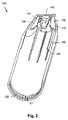
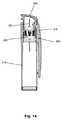
図1を参照し、ペン型薬剤送達装置1を説明する。ペンは、キャップ部(または「ペンキャップ」)100と、薬剤放出機構が配置される近位部4を有する主要部3と、注射針が貫通可能な遠位隔壁を有する、薬剤を充填した透明なカートリッジ6が、近位部に取り付けられたカートリッジホルダ7によって所定の位置に配置され保持される、遠位リザーバ部5とを含み、カートリッジホルダは、カートリッジの一部を点検することを可能にする開口を有する。カートリッジは、放出機構の一部を形成するピストンロッド9によって駆動するピストン8を備える。最近位ボタン10は、望ましい用量の薬剤を手動でセットして放出するように機能する。この種類のペン型薬剤送達装置はよく知られており、例えば、この種類のペンの内部構造に関して更に詳しく言及している国際公開第99/38554号パンフレットを参照されたい。この実施形態では、ペンは、薬剤を予め満たした使い捨て装置であり、カートリッジホルダは、主要部の近位部に取り外しできないように取り付けられており、また、注射針アセンブリの雌ネジ山に係合する雄ネジ山をこの例では有する、ハブマウント11の形態の遠位連結手段を備える。以下を参照されたい。また、ペンは「耐久性のある」装置であってもよく、カートリッジホルダは主要部に着脱可能に取り付けられ、これにより、ピストンロッドを押し戻し、新しいカートリッジを取り付けることができる。そのような配置では、注射針アセンブリの接続部は、カートリッジの一部であってもよい。 The pen type drug delivery device 1 will be described with reference to FIG. The pen has a cap portion (or “pen cap”) 100, a main portion 3 having a proximal portion 4 in which a drug release mechanism is disposed, and a drug-filled transparent having a distal septum through which an injection needle can pass. And a distal reservoir portion 5 that is placed and held in place by a cartridge holder 7 attached to the proximal portion, which allows the cartridge holder to inspect a portion of the cartridge Has an opening. The cartridge comprises a piston 8 that is driven by a piston rod 9 that forms part of a release mechanism. The
不透明材料製のペンキャップ100は、近位閉端および遠位開口102、ポケットクリップ103ならびに点検用開口104を有する、一般に筒状のスリーブまたは筐体101を含む。近位端は、2つの対向する一般に平面の把持面110を備える。 The
更に、図1は、ペン型装置のハブマウント11の雄ネジ山に接続するネジ山の形態の内側連結手段を有するカップ型ハブ22に取り付けられる中空注入針21を含む注射針アセンブリを示す。注射針はハブから突出する尖った遠位部と、ハブ22がネジ山に取り付けられる場合にカートリッジ隔壁を貫通する尖った近位部とを含む。別の実施形態では、ネジ接続の代わりに差込継手を使用してもよく、例えば、カップは、内部に突出する複数の突起を備えてもよく(図6を参照)、突起は、ペン型装置で遠位に形成した対応する溝に係合する。注射針アセンブリは、ハブに着脱可能に係合する裾部24を備える注射針キャップ23を更に含み、これにより、注射針の遠位端を保護する。通常、注射針は、剥離膜によって封止した開口を有する容器(図示せず)内に無菌状態で設けられ、容器は、解放可能な状態、例えば、注射針ハブに摩擦係合する状態にある。ペン型薬剤送達装置1および注射針アセンブリは共にシステムを形成する。 Further, FIG. 1 shows an injection needle assembly including a
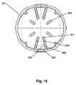
ペンキャップ100の断面図を示す図2および図3を参照すると、ペンキャップは、注射針キャップに係合する多くの構造と同じように、主要部に対応する連結構造12を解放可能に係合するために、遠位端に連結手段120、121を備える。更に具体的には、ペンキャップは、把持面110の内側に対応して配置される2対の把持リブ130を備える。ペンキャップは、互いに2つの把持面を押し付ける比較的柔軟性のあるポリマー材料から製造されるので、例えば、第1および第2の指でペンキャップを把持する場合、2対のリブが互い離れることによって注射針キャップに係合すると、注射針キャップはリブ間に配置され、これにより、注射針ハブから注射針キャップを取り除くことができる。以下を参照されたい。また、キャップは、注射針キャップに係合するように把持構造を動作させるように作用するボタン部材を備えてもよい。ペンキャップは、注射針ハブから注射針キャップを取り除く際に、ペンキャップ内の所定の位置で注射針キャップに係合してこれを保持する1対の把持フランジ140を更に含むが、これらの把持フランジは、注射針ハブから注射針キャップを取り除ける程度に十分強いグリップを確保しない。キャップの閉端から突出する突起141は、注射針キャップを正しく横方向に配置することを確実にする。この実施形態では、ペンキャップは、取り付けられたハブを横方向に配置するように機能する複数の縦リブ150を更に備え、各リブは遠位当接面151を備える段状構造を有し、これにより、対応するように設計されたカートリッジホルダ7のみを取り付けるようにペンキャップを識別することができる。これは、キャップを併用することが意図されるペン型装置に含む薬剤の種類に対応して、ペンキャップが例えば色識別される場合に有用となりうる。 2 and 3, which show a cross-sectional view of the
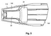
図4は、注射針アセンブリおよびペンキャップがペン主要部に取り付けられる位置に対応してペンキャップ100内に配置される注射針キャップ23を示す。2つの把持表面110および把持リブ130は、ペンキャップと注射針キャップとの間には係合がない初期の解放位置にある。 FIG. 4 shows a
図5では、2つの把持表面110が互いに離れることで、ペンキャップと注射針キャップとの間に把持係合がもたらされ、これによって、ペン主要部からペンキャップを取り除く場合、使用状態で注射針ハブから注射針キャップを取り除くことができる。使用者が把持表面110で圧力を緩める場合、把持フランジ140は、ペンキャップを再び嵌めるまで所定の位置に注射針キャップを適切に保持するように機能する。点検用開口104は、注射針キャップの裾部24が所定の位置にあれば、使用者が制御可能となるように配置され、ペンキャップを取り除く必要がない。注射針アセンブリが取り付けられているものの注射針キャップがない場合は、使用者は開口を通して注射針ハブの遠位部を見ることができるようになる。一方、注射針ハブが取り付けられていない場合、注射針キャップは「空」のように見え、すなわち、ペンキャップがペン主要部に取り付けられるとき、開口104は、連結手段11の遠位端に遠位に配置される。 In FIG. 5, the two
明らかなように、把持フランジ140は、注射針キャップが注射針ハブに再び取り付けられるまで、注射針キャップに係合してこれを保持するように設計される。使用者は、注射針キャップを最初に注射針ハブに取り付けないで取り除く場合、開端を有するペンキャップを下向きに持ち、注射針キャップが解放されて落ちるまで固体面を軽く叩く。また、ペンキャップは、追加の使用者作動把持手段、例えば、図6の実施形態に関して以下に説明する種類のものを備えてもよく、これにより、使用者による制御性や使い易さが改善する。 As will be apparent, the
図2に示すように、キャップは、主要部にキャップを取り付けるための連結手段120、121を備えてもよい。この実施形態では、円周溝120は、キャップが所定の場所に軸方向に確実に係止することができる一方、1または複数の凹み121の形態の第2の種類の連結部は、キャップを確実に回転係止することができる。例えば、90°間隔に4つ凹みを設けることによって、キャップ部は第1の取付位置と第2の取付位置との間で回転可能となり、第1の取付位置では、カートリッジホルダ7に開口260を配置し、これにより光を遮断し、第2の取付位置では、透明なカートリッジに開口を配置し、これにより使用者がリザーバを点検することができる。 As shown in FIG. 2, the cap may include connecting
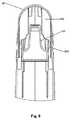
図6〜10を参照し、更なるペンキャップ900を説明する。図2の実施形態のようなペンキャップは、注射針ハブおよび注射針キャップを含む注射針アセンブリの構成要素に係合する他の多くの構造と同じように、薬剤送達装置の主要部に対応する連結構造12に着脱可能に係合するために開端(図示しない)で連結手段を備えている。 A
更に具体的には、ペンキャップ900は、注射針キャップを把持するための第1の把持手段と、注射針ハブを保持するための第2の把持手段と、主要部からペンキャップを取り除いた際に所定の位置で注射針キャップを把持するための追加の把持手段の3つ方式の把持手段3を備えるキャップ筐体901を含み、把持機能は、使用者作動手段によって制御される。 More specifically, the
図6および図10に戻ると、2対の把持リブ930が、1対の第1の対向作動面910の内側に対応して配置されている。各リブは、注射針キャップの遠位管状部23に係合する把持縁部931と、注射針キャップの裾部24の遠位当接面に係合する近位当接突出部932と、裾部24の外接面に係合するフレキシブルアーム933とを含む(以下参照)。ペンキャップ把持縁部931と注射針キャップとの間のグリップを作動させると、注射針キャップを、主要部に連結した注射針ハブとの把持係合から確実に解放することができる。この実施形態では、グリップは摩擦によるものであるが、別の実施形態では、グリップは、ペンキャップと注射針キャップそれぞれに対応する連結構造を備えてもよい。キャップの閉端から突出する内部突起940は、注射針キャップを確実に正しく横方向に配置する。 Returning to FIG. 6 and FIG. 10, two pairs of gripping
キャップは、1対の第2の対向作動面911の内側に対応して配置される2対の比較的短い把持突起950を更に備え、この突起は、注射針アセンブリのカップ型ハブ22の外接面に係合する。この実施形態では、ハブは、作動時に移動する円周状の比較的浅い溝(または円周溝部)を備え、突起は、作動時にこの溝へと移動する。ペンキャップ突起950と注射針ハブとの間のグリップを作動させると、主要部から注射針ハブを解放するために、注射針ハブを、ペンキャップと共に確実に回転させることができる。差込継手またはネジ接続のどちらを設けるかによって、キャップはほんの僅かに、例えば45°、または何回か回転させてもよい。更に、注射針ハブがハブマウント11から解放される場合、ペンキャップ突起950と注射針ハブとの間のグリップは、注射針ハブがペンキャップと共に主要部から確実に軸方向に離れることができるようになる。差込継手を設ける場合、注射針ハブは通常、ハブマウント11を解放するために捻る際、軸方向に移動せず、これによって、注射針アセンブリのネジを外すペンキャップの軸方向の動作に適合させる必要がないことから、ペンキャップの構造が更に簡易なものとなる。そうでない場合、使用者は、注射針ハブと共に主要部からペンキャップのネジを外す必要があるということになる。 The cap further includes two pairs of relatively short
この実施形態では、ペンキャップ筐体901は比較的柔軟性のあるポリマー材料から製造される。したがって、2つの対向作動面910、911を互いに押し付けると、例えば、第1および第2の指でペンキャップを把持すると、ペンキャップは楕円状に圧迫され、把持手段の下部(すなわち、把持縁部931または把持突起950)は互いの方向に向かって移動し、このため、注射針キャップが把持リブ間に配置されると、注射針ハブおよび注射針キャップそれぞれに係合し、これにより、注射針ハブおよび主要部から注射針キャップおよび注射針ハブをそれぞれ取り除くことができる。以下を参照されたい。しかし、ペンキャップの実際の設計によっては、1対の作動面が作動すると、両方の把持システムが実際に作動するのが見られる場合もある。これに応じて、この実施形態では、第2の把持手段と注射針ハブとの間の軸グリップは比較的弱く、注射針ハブが主要部に連結した状態にある場合、作動した第2の把持手段を係合状態から軸方向に引き抜くことができる。したがって、2対の対向作動面は、(例えば、図6に示す2対の作動面間で軸方向に配置される)1対の作動面に代えてもよく、これにより、ユーザインタフェースが簡易なものとなる。また、キャップは、例えば、2つの把持システム全体を完全に制御する配置となるように、注射針キャップに係合するように把持構造を動作させる別個の第1および第2のボタン部材を備えてもよい。 In this embodiment, the
上記のフレキシブルアーム933は、追加の把持手段(または保持手段)を備え、追加の把持手段に対して90°ずれた第3の対向作動面(図示せず)に関連する。このため、第3の対の対向作動面を互いに押し付けると、柔軟性のあるペンキャップは楕円状に圧迫され、この作用によってアーム933は互いに離れ、これにより、取り付けられた注射針キャップを解放する。本願の図面を作成するのに使用したドローソフトは、屈曲形状の構造を示すことができないことに留意する必要がある。これに応じて、「屈曲」アーム933は、実際には係合する表面の背後に隠れているように示す。特定の実施形態では、追加の作動面の1つは、例えば、図3のクリップ103に対応するように、クリップに一体化してもよい。特定の実施形態では、クリップの非自由端は、クリップの長さに沿った3つの支点によって筐体に接続してもよく、支点間には間隙がある。上部および下部の支点は主にクリップを支持するが、中間部の支持点は作動面の1つに配置される。この配置によって、使用者はクリップの中間支点に対応して筐体を楕円状に圧迫することができる。 The
したがって、追加の把持手段には、キャップ部と、取り付けられた注射針キャップとの間に、把持係合をもたらし、ハブマウントに取り付けられたハブから注射針キャップを取り除くか、あるいは、注射針キャップが取り付けられたハブを主要部から取り除いた後にキャップ部に把持係合して注射針キャップを保持するために十分強く、ハブマウントに取り付けられたハブから注射針キャップを取り除かずに主要部からキャップ部を取り除くために十分弱い最初の非作動状態と、追加の把持手段と注射針キャップの間には把持係合がなく、これにより、主要部からキャップ部を取り除いた後に、例えば、ペンキャップが上下逆向きに保持される際の重力によって、キャップ部から注射キャップを取り除くことができる第2の作動状態とがある。 Thus, the additional gripping means provides a gripping engagement between the cap portion and the attached needle cap, and removes the needle cap from the hub attached to the hub mount, or the needle cap. After removing the hub attached to the main part, it is strong enough to hold the needle cap by gripping engagement with the cap part, and cap from the main part without removing the needle cap from the hub attached to the hub mount. There is no gripping engagement between the initial inoperative state, which is weak enough to remove the part, and the additional gripping means and the needle cap, so that after removing the cap part from the main part, for example, the pen cap There is a second operating state in which the injection cap can be removed from the cap portion by gravity when being held upside down.
次に、様々な使用状態に関して説明する。図6は、注射針アセンブリを示し、注射針ハブ22とその上に取り付けられた注射針キャップを含み、注射針キャップは、使用状況に対応してペンキャップ内に配置され、注射針アセンブリおよびペンキャップは、薬物送達システムの主要部に取り付けられている。突起932によって、注射針キャップが軸方向に確実に正しく配置されるようになる。図に明らかであるように、第1および第2の把持手段は非作動状態にあり、これにより、注射針ハブおよび注射針キャップを所定の位置に残しながら、主要部からペンキャップを取り除くことができ、これにより、さらなる把持手段は、上記に記載するように注射針キャップとの係合状態から滑り出ることができる。図8は、注射針キャップが第1の把持手段の作動によって注射針ハブから取り除かれている状態を示し、注射針キャップは、追加の把持手段933によって所定の位置に保持されている。上に示すように、この状態には、第1および第2の把持手段を同時に作動させることによって遷移してもよく、第2の把持手段の設計によって、主要部に強固に接続した注射針ハブとの係合状態から第2の把持手段を引き抜くことができる。図9または図7に示すように、ペンキャップを上下逆方向に保持して追加の把持手段を作動させると、注射針キャップは、重力によって注射針ハブと共に落ちる。注射針ハブと、その上に取り付けられた注射針アセンブリとを取り除くために、使用者は、最初に注射針ハブを捻るか、あるいは、主要部のハブマウントとの係合状態から軸方向に引き抜くことを可能にする第2の把持手段を作動させ(第1の把持手段を同時に作動させてもこの機能性に影響を及ばさない)、次に、主要部からペンキャップを軸方向に引き抜く。注射針キャップと追加の把持手段との間の保持グリップが対応するように設計される場合、注射針ハブが注射針キャップによって軸方向に移動するため、軸方向への移動時に第2の把持手段を必ずしも作動させなくてもよい。実際には、注射針キャップが取り付けられない場合は、注射針ハブは追加の把持手段によってペンキャップ内の所定の位置に保持されないため、第2の把持手段はペンキャップが軸方向に移動する時も作動する必要がある。 Next, various usage states will be described. FIG. 6 shows a needle assembly that includes a
上記の開示をまとめると、図2〜5を参照して、注射針キャップを把持する使用者作動把持手段を有するペンキャップの実施形態を説明し、図6〜10を参照して、注射針キャップと注射針ハブの両方を把持する使用者作動把持手段を有するペンキャップの実施形態を説明した。図11〜15を参照して、注射針ハブを把持する使用者作動把持手段を有する本発明の実施形態を説明する。 In summary of the above disclosure, with reference to FIGS. 2-5, an embodiment of a pen cap having user-operated gripping means for gripping the needle cap will be described, and with reference to FIGS. An embodiment of a pen cap having user-operated gripping means for gripping both the needle hub and the needle hub has been described. With reference to FIGS. 11-15, an embodiment of the present invention having user-actuated gripping means for gripping a needle hub will be described.
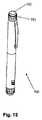
図11は、図1に示す種類のペン型薬剤送達装置の本体部分と共に使用するペンキャップ200を示す。キャップは、取り付けられた注射針ハブ(図示しない)にキャップを係合させることを可能にする使用者作動ボタン220を備えるキャップ筐体210を含む。 FIG. 11 shows a
図12は、組み立て前のペンキャップの構成要素を示す図である。ボタン220は、使用者がボタンに軸方向下向きの力を加えることを可能にする上面221と、多くの軸方向スロット224によって区分223に分割された裾部222とを含む。スロットの1つは、キャップ筐体の内側突起(バネ支点215、図13参照)を通過するように滑り、更に、組み立て後に2つの部品が脱離しない、1対の対向するフレキシブルアーム229を備える。 FIG. 12 is a diagram showing components of the pen cap before assembly.
図13は、取り付けられた注射針ハブ322にキャップを係合させることを可能にする使用者作動ボタン220を備えるキャップ筐体210を含むペンキャップ200の断面図を示す(図4参照)。ボタンは、最初に完全に伸びて「ボタンが上がった」位置と完全に押し下げられて「ボタンが下がった」位置との間でボタンを移動させることを可能にする軸筐体リブ214に係合するスロット224によって筐体内で軸方向に案内され、ボタンバネ支点225と筐体バネ支点215との間で支持されるバネ(図示しない)は、伸びた位置にボタンを確実に付勢する。この実施形態では、裾部222は、4つのスロット224によって4つの90°の区分223に分割される。各区分は、取り付けられた注射針の一部に係合する把持手段を備える。この実施形態では、裾部の各区分は、ハブ止め316の外側リブに軸方向に係合する多くの内面リブ226を備え(図14参照)、これにより、2つの構成要素間に回転係止をもたらす。裾部の区分の下縁部は、下向きに傾斜して内側に面する円周面227を備え、円周面は、キャップ筐体の内壁に配置された円周状リブ219上の対応する上方向外側に面する傾斜面217を軸方向に係合し、これにより、ボタンが下向きに押されて傾斜面216に係合すると、裾部の区分は外側に押し出され、更に、ボタンの軸方向の移動を停止する。 FIG. 13 shows a cross-sectional view of a
図13〜15を参照して、ペン本体から注射針アセンブリを取り外すのに有用なペンキャップ200の使用を説明する。 With reference to FIGS. 13-15, the use of a
図13は、最初の上方向に付勢した位置にあるキャップボタン210を示す。キャップボタンが注射針アセンブリ300を備えるペン本体に取り付けられるとき、図14に示すように、注射針ハブ322および注射針321は、キャップ筐体に関連して配置されうる。また、ペンキャップは、注射針キャップと共に取り付けられた際に、注射針キャップ(図示しない)を収容する。 FIG. 13 shows the
注射針アセンブリを取り外すために、使用者は最初に、ペン本体に設けた停止位置(図示しない)まで、あるいは、使用者がボタンと注射針ハブとの間に係合を感じるまでボタンを押し下げ、これにより、裾部の区分は注射針ハブの外面に係合して把持する。図14を参照されたい。例えば摩擦によるグリップの「力」と、スプリングによってもたらされる復帰力に応じて、ボタンは、使用者がボタンから力を解放した時、あるいは、使用者がボタンを能動的に引き出した時に、初期位置に戻ってもよい。しかし、使用者がボタンを押し下げてペン本体に対してペンキャップを回転させる場合、注射針ハブはペン本体に対して回転し、これにより、ペン本体から注射針ハブのネジを外すことができる。注射針アセンブリとペン本体との間の連結部が従来のネジ山である場合、キャップを何回か回転させる必要があるが、差込み型のものであれば、単に短く捻ることのみ必要とされる。従来のネジ山が使用される場合、注射針ハブは、裾部の区分間で軸方向に移動でき、ハブはペン本体から回転して外れ、注射針が薬剤カートリッジから完全にまたは一部出てくる。注射針アセンブリがペン本体から外れると、使用者は、裾部の区分によって把持係合状態で保持される注射針アセンブリと共にペン本体からペンキャップを取り除くことができる。ペンキャップから注射針アセンブリを取り除くために、使用者はこの時点でペンボタンを完全に押し下げ、これにより、裾部の区分の下縁部はキャップ筐体の傾斜面に係合(図15を参照)し、このため、裾部の区分を外側に押し出すことによって注射針ハブとの係合状態から押し出され(図15に示さず)、これにより、例えば、重力によって、注射針キャップから注射針アセンブリを取り除くことができる。注射針アセンブリがキャップから解放され、使用者がボタンから力を緩めると、ボタンはバネ230によって初期位置に戻る。 To remove the needle assembly, the user first pushes the button down to a stop position (not shown) on the pen body or until the user feels engagement between the button and the needle hub, As a result, the skirt section engages and grips the outer surface of the needle hub. See FIG. Depending on the grip “force” due to friction, for example, and the restoring force provided by the spring, the button will be in its initial position when the user releases the force from the button or when the user actively pulls the button. You may return to However, when the user pushes the button down and rotates the pen cap relative to the pen body, the needle hub rotates relative to the pen body, thereby unscrewing the needle hub from the pen body. If the connection between the needle assembly and the pen body is a conventional thread, the cap will need to be rotated several times, but if it is a plug-in type, it will only require a short twist . When conventional threads are used, the needle hub can move axially between the skirt sections, the hub rotates off the pen body, and the needle is fully or partially out of the drug cartridge. come. When the needle assembly is removed from the pen body, the user can remove the pen cap from the pen body with the needle assembly held in gripping engagement by the skirt segment. To remove the needle assembly from the pen cap, the user now fully depresses the pen button so that the lower edge of the skirt section engages the ramp surface of the cap housing (see FIG. 15). And therefore pushed out of engagement with the needle hub by pushing the skirt section outward (not shown in FIG. 15), so that, for example, by gravity, the needle assembly is removed from the needle cap. Can be removed. When the needle assembly is released from the cap and the user releases the force from the button, the button is returned to its initial position by the spring 230.
言い換えれば、このペンキャップは、(i)注射針アセンブリがペン本体に取り付けられるとき、取り付けられたペンキャップと注射針ハブとの間に把持係合がない第1の状態と、(ii)取り付けられたペンキャップが、ペン本体に取り付けられた注射針アセンブリの注射針ハブに把持係合し、これにより、ペン本体からキャップ部を取り除く際に、ペンキャップと共にペン本体から注射針アセンブリを取り除くことができる第2の状態と、(iii)把持手段によってペンキャップと把持係合されている注射針ハブが把持手段から解放され、これにより、ペンキャップから注射針アセンブリを取り除くことができる第3の状態との間で動作する。 In other words, the pen cap includes (i) a first state in which there is no gripping engagement between the attached pen cap and the needle hub when the needle assembly is attached to the pen body; The attached pen cap grips and engages the needle hub of the needle assembly attached to the pen body, thereby removing the needle assembly from the pen body together with the pen cap when removing the cap portion from the pen body. And (iii) a third state in which the needle hub that is in gripping engagement with the pen cap by the gripping means is released from the gripping means, thereby removing the needle assembly from the pen cap. Operate between states.
図1〜15を参照し、本発明の原理を組み込むペンキャップの第1の実施形態を示すが、その原理は、薬剤送達装置の主要部、例えばペン本体からペンキャップを取り除くために、注射針ハブに係合したり、解放したりする望ましい機能性をもたらす他の多くの配置によって実現することができる。図16〜20に、そのような多くの代替例を示す。 Referring to FIGS. 1-15, a first embodiment of a pen cap incorporating the principles of the present invention is shown, which principles include an injection needle for removing a pen cap from a major portion of a drug delivery device, such as a pen body. Many other arrangements that provide the desired functionality of engaging and releasing the hub can be achieved. Figures 16-20 illustrate many such alternatives.
更に具体的には、図16は薬剤送達装置400の実施形態を示し、上記の実施形態と同様、ペン本体403と単一の使用者操作押ボタン420を有するペンキャップ410とを含むが、ボタンの第1の押しによって、ペンキャップに対して軸方向に回転する注射針ハブを係止して注射針のネジを外すことを可能にする機構が設けられる。押ボタンは、注射針ハブのネジを外した後も装置キャップ内に留まる。ボタンの第2の押しによって、キャップから注射針ハブを解放し、ボタンの第3の押しによって、ボタンを初期位置に戻す。明らかなように、この実施形態は、典型的なボールペン機構に類似したユーザインタフェースを設ける。 More specifically, FIG. 16 shows an embodiment of a
図17は、第1および第2の使用者操作押ボタン521、522を含むペンキャップ510を備える薬剤送達装置500の実施形態に示す。第1のボタン521の第1の押しによって、ペンキャップに対して軸方向に回転する注射針ハブを係止して注射針のネジを外すことができる。押ボタンは、注射針ハブのネジを外した後も装置キャップ内に留まる。第2のボタン522の第2の押しによって、キャップから注射針ハブを解放し、その後、キャップを初期位置に戻す。 FIG. 17 shows an embodiment of a
図18は、第1および第2の使用者操作押ボタン621、622を含むペンキャップ610を備える薬剤送達装置600の実施形態を示す。第1のボタン621の第1の押しによってペンキャップに対して軸方向に回転する注射針ハブを係止して注射針のネジを外すことができる。押ボタンは、注射針ハブのネジを外した後も装置キャップ内に留まる。第2のボタン622の第2の押しによってキャップから注射針ハブを解放し、その後、キャップを初期位置に戻す。 FIG. 18 shows an embodiment of a
図19は、使用者操作リング部材721および使用者操作押ボタン722を含むペンキャップ710を備える薬剤送達装置700の実施形態を示す。このボタンを押し下げると、ペンキャップに対して軸方向に回転する注射針ハブを係止して注射針のネジを外すことができる。押ボタンは、注射針のネジを外した後も装置キャップ内に留まる。リング部材を例えば時計回りに捻ることによってキャップから注射針ハブを解放し、その後、例えば、使用者がリング部材を回転させて初期位置に戻すか、あるいは、バネがリング部材を回転させて初期位置に戻すことによって、キャップは初期位置に戻る。 FIG. 19 illustrates an embodiment of a
図20は、使用者操作リング部材820を含むペンキャップ810を備える薬剤送達装置800の実施形態を示す。第1の方向にリング部材を例えば反時計回りに回転させることによって、ペンキャップに対して軸方向に回転する注射針ハブを係止して注射針のネジを外すことができる。押ボタンは、注射針のネジを外した後も装置キャップ内に留まる。リング部材を例えば反対方向に回転させると、キャップから注射針ハブを解放し、その後、例えば、使用者がリング部材を回転させて初期位置に戻すか、あるいは、バネがリング部材を回転させて初期位置に戻すことによって、キャップは初期位置に戻る。 FIG. 20 illustrates an embodiment of a
好ましい実施形態の上記の記載では、本発明の概念が当業者に明らかになる程度に、様々な構成要素に記載した機能性をもたらす様々な構成および手段を説明している。様々な構成要素の詳細な構成および仕様は、本願仕様書の記載に従って当業者により実施される通常の設計手順の対象であるとみなす。 The above description of the preferred embodiments describes various configurations and means for providing the functionality described in the various components to the extent that the inventive concept becomes apparent to those skilled in the art. The detailed configuration and specifications of the various components are considered the subject of normal design procedures performed by those skilled in the art as described in the specification of the present application.
Claims (14)
Translated fromJapanese− 薬剤リザーバ(6)または薬剤リザーバを受けるための手段と、
− 前記リザーバから薬剤を放出するための薬剤放出手段(9)と
を含む主要部(3、403)と、
(b)注射針アセンブリ(20、300)であって、
− 前記主要部に取り付けられる注射針ハブ(22、322)と、
− 前記注射針ハブに取り付けられ、尖った遠位端と、前記ハブが前記主要部に取り付けられると前記リザーバと流体連結するように配置される近位端とを含む中空針(21、321)と、
− 前記尖った遠位端を覆うために、前記ハブに着脱可能に取り付けられる注射針キャップ(23)と
を含む注射針アセンブリ(20、300)と、
(c)前記主要部に着脱可能に取り付け可能なキャップ部(100、200、900)であって、
− (i)前記注射針アセンブリが前記主要部に取り付けられるとき、取り付けられたキャップ部の第1の把持手段と、注射針アセンブリの所定の第1の部品との間に把持係合がなく、これにより、前記主要部から前記所定の第1の部品を取り除かずに、前記主要部からキャップ部を取り除くことができる第1の状態と、
(ii)キャップ部の第1の把持手段が、前記主要部に取り付けられた注射針アセンブリの前記所定の第1の部品に把持係合でき、これにより、キャップ部が前記主要部から取り除かれる際に、前記所定の第1の部品と共に前記主要部からキャップ部を取り除くことができる第2の状態と
の間で可逆的に動作可能な第1の把持手段(130、223、931、950)と、
− 上記2つの状態の間で前記第1の把持手段を動作させる第1の使用者作動手段(110、220、910、911)と
を含むキャップ部(100、200、900)と
を備える、薬物送達システム(1400)。(A) the main part (3, 403),
-Means for receiving a drug reservoir (6) or drug reservoir;
A main part (3, 403) comprising a drug release means (9) for releasing the drug from the reservoir;
(B) a needle assembly (20, 300) comprising:
A needle hub (22, 322) attached to the main part;
A hollow needle (21, 321) attached to the needle hub and comprising a pointed distal end and a proximal end arranged to be in fluid communication with the reservoir when the hub is attached to the main part; When,
A needle assembly (20, 300) comprising a needle cap (23) removably attached to the hub to cover the pointed distal end;
(C) a cap part (100, 200, 900) that can be detachably attached to the main part,
(I) when the needle assembly is attached to the main part, there is no gripping engagement between the first gripping means of the attached cap part and the predetermined first part of the needle assembly; Thereby, the first state in which the cap portion can be removed from the main portion without removing the predetermined first part from the main portion;
(Ii) the first gripping means of the cap part can be gripped and engaged with the predetermined first part of the injection needle assembly attached to the main part, whereby the cap part is removed from the main part; And a first gripping means (130, 223, 931, 950) operable reversibly between the second state in which the cap part can be removed from the main part together with the predetermined first part; ,
A drug comprising a cap part (100, 200, 900) comprising first user actuating means (110, 220, 910, 911) for operating said first gripping means between said two states Delivery system (1400).
− (i)前記注射針アセンブリが前記主要部に取り付けられるとき、取り付けられたキャップ部の第2の把持手段と、注射針アセンブリの注射針ハブとの間に把持係合がなく、これにより、前記主要部から前記注射針ハブを取り除かずに、前記主要部から前記キャップ部を取り除くことができる第1の状態と、
(ii)前記キャップ部の第2の把持手段が、前記主要部に取り付けられた注射針アセンブリの前記注射針ハブに把持係合でき、これにより、前記注射針ハブを前記主要部から取り外し、取り外した前記注射針ハブと共に前記主要部から前記キャップ部を取り除くことができる第2の状態と
の間で可逆的に動作可能な第2の把持手段(950)と、
− 上記2つの状態の間で前記第2の把持手段を動作させる第2の使用者作動手段(911)と
を更に含む、請求項2に記載の薬物送達システム。The cap part is
-(I) when the needle assembly is attached to the main part, there is no gripping engagement between the second gripping means of the attached cap part and the needle hub of the needle assembly, thereby A first state in which the cap portion can be removed from the main portion without removing the needle hub from the main portion;
(Ii) The second gripping means of the cap portion can be gripped and engaged with the needle hub of the needle assembly attached to the main portion, thereby removing and removing the needle hub from the main portion. A second gripping means (950) operable reversibly between a second state in which the cap part can be removed from the main part together with the injection needle hub;
The drug delivery system according to claim 2, further comprising second user actuating means (911) for operating the second gripping means between the two states.
(a)前記主要部に取り付けられた注射針ハブから注射針キャップを取り除いた後に前記キャップ部に把持係合して注射針キャップを保持するために十分強く、
(b)前記主要部に取り付けられた注射針ハブから注射針キャップを取り除かずに前記主要部から前記キャップ部を取り除くために十分弱い
グリップとなる、請求項2〜5のいずれか1項に記載の薬物送達システム。The cap portion includes additional gripping means (140) for gripping and engaging the cap portion and the attached injection needle cap, the additional gripping means comprising:
(A) strong enough to hold the needle cap in gripping engagement with the cap portion after removing the needle cap from the needle hub attached to the main portion;
(B) It becomes a grip weak enough to remove the cap part from the main part, without removing the needle cap from the needle hub attached to the main part. Drug delivery system.
− 追加の把持手段(933)であって、
(i)追加の把持手段が、前記キャップ部と、取り付けられた注射針キャップとを把持係合する第1の状態であって、
(a)前記主要部に取り付けられた注射針ハブから前記注射針キャップを取り除くか、あるいは、前記主要部から前記注射針キャップが取り付けられた注射針ハブを取り除いた後に、前記キャップ部に把持係合して前記注射針キャップを保持するために十分強く、
(b)前記主要部に取り付けられた注射針ハブから前記注射針キャップを取り除かずに前記主要部から前記キャップ部を取り除くために十分弱い
第1の状態と、
(ii)追加の把持手段と前記注射針キャップとの間に把持係合がなく、これにより、前記主要部から前記キャップ部を取り除いた後に前記キャップ部から前記注射キャップを取り除くことができる第2の状態と
の間で可逆的に動作可能である追加の把持手段と、
− 上記2つの状態の間で前記追加の把持手段を動作させる追加の使用者作動手段と
を更に含む、請求項2〜5のいずれか1項に記載の薬物送達システム。The cap part is
-Additional gripping means (933),
(I) In a first state, the additional gripping means grips and engages the cap portion and the attached injection needle cap,
(A) After removing the injection needle cap from the injection needle hub attached to the main part, or after removing the injection needle hub to which the injection needle cap is attached from the main part, Strong enough to hold the needle cap together,
(B) a first state that is weak enough to remove the cap portion from the main portion without removing the needle cap from the needle hub attached to the main portion;
(Ii) There is no gripping engagement between the additional gripping means and the injection needle cap, whereby the injection cap can be removed from the cap portion after the cap portion is removed from the main portion. Additional gripping means operable reversibly between the states of
6. A drug delivery system according to any one of claims 2 to 5, further comprising additional user actuating means for operating said additional gripping means between said two states.
(i)注射針アセンブリが前記主要部に取り付けられるとき、取り付けられた前記キャップ部と注射針ハブとの間に把持係合がない第1の状態と、
(ii)取り付けられたキャップ部が、前記主要部に取り付けられた注射針アセンブリの注射針ハブに把持係合し、これにより、前記主要部から前記キャップ部を取り除く際に、前記キャップ部と共に前記主要部から前記注射針アセンブリを取り外して取り除くことができる第2の状態と、
(iii)前記把持手段によって把持係合に保持される注射針ハブが前記把持手段から解放され、これにより、前記キャップ部から前記注射針アセンブリを取り除くことができる第3の状態と
の間で可逆的に動作可能であり、
前記第1の使用者作動手段(220)が、上記3つの状態の間で前記第1の把持手段を動作させる、
請求項1に記載の薬物送達システム。The predetermined first part is an injection needle hub, and the first gripping means (223, 226) includes:
(I) when the injection needle assembly is attached to the main portion, a first state where there is no gripping engagement between the attached cap portion and the injection needle hub;
(Ii) The attached cap portion is gripped and engaged with the needle hub of the injection needle assembly attached to the main portion, whereby the cap portion is removed together with the cap portion when the cap portion is removed from the main portion. A second state in which the needle assembly can be removed and removed from the main part;
(Iii) The needle hub held in gripping engagement by the gripping means is released from the gripping means, thereby reversing between a third state in which the needle assembly can be removed from the cap portion. Are operational,
The first user actuating means (220) operates the first gripping means between the three states;
The drug delivery system according to claim 1.
Applications Claiming Priority (11)
| Application Number | Priority Date | Filing Date | Title |
|---|---|---|---|
| US18655009P | 2009-06-12 | 2009-06-12 | |
| EP09162593.9 | 2009-06-12 | ||
| US61/186,550 | 2009-06-12 | ||
| EP09162593 | 2009-06-12 | ||
| EP09170836 | 2009-09-21 | ||
| EP09170836.2 | 2009-09-21 | ||
| EP09174414 | 2009-10-29 | ||
| EP09174414.4 | 2009-10-29 | ||
| US25804009P | 2009-11-04 | 2009-11-04 | |
| US61/258,040 | 2009-11-04 | ||
| PCT/EP2010/058322WO2010142813A1 (en) | 2009-06-12 | 2010-06-14 | Drug delivery device with cap functions for needle assembly |
Publications (1)
| Publication Number | Publication Date |
|---|---|
| JP2012529322Atrue JP2012529322A (en) | 2012-11-22 |
Family
ID=42651065
Family Applications (1)
| Application Number | Title | Priority Date | Filing Date |
|---|---|---|---|
| JP2012514495ACeasedJP2012529322A (en) | 2009-06-12 | 2010-06-14 | Drug delivery device with cap function for needle assembly |
Country Status (5)
| Country | Link |
|---|---|
| US (1) | US8529518B2 (en) |
| EP (1) | EP2440270B1 (en) |
| JP (1) | JP2012529322A (en) |
| CN (1) | CN102802704A (en) |
| WO (1) | WO2010142813A1 (en) |
Cited By (6)
| Publication number | Priority date | Publication date | Assignee | Title |
|---|---|---|---|---|
| JP2016533214A (en)* | 2013-10-18 | 2016-10-27 | サノフィ−アベンティス・ドイチュラント・ゲゼルシャフト・ミット・ベシュレンクテル・ハフツング | Injection device |
| JP2017505675A (en)* | 2014-02-11 | 2017-02-23 | イーライ リリー アンド カンパニー | Cap assembly for gripping rigid needle shield |
| KR20170078800A (en)* | 2014-12-03 | 2017-07-07 | 일라이 릴리 앤드 캄파니 | Needle shield puller cap assembly |
| JP2019503251A (en)* | 2015-01-30 | 2019-02-07 | ベクトン・ディキンソン・アンド・カンパニーBecton, Dickinson And Company | Pen needle assembly |
| JP2019530537A (en)* | 2016-10-13 | 2019-10-24 | サノフィ−アベンティス・ドイチュラント・ゲゼルシャフト・ミット・ベシュレンクテル・ハフツング | Drug delivery device |
| US11577030B2 (en) | 2013-12-04 | 2023-02-14 | Embecta Corp. | Pen needle attachment mechanisms |
Families Citing this family (45)
| Publication number | Priority date | Publication date | Assignee | Title |
|---|---|---|---|---|
| US12097357B2 (en) | 2008-09-15 | 2024-09-24 | West Pharma. Services IL, Ltd. | Stabilized pen injector |
| EP2403572B1 (en) | 2009-03-03 | 2019-01-16 | Becton, Dickinson and Company | Pen needle assembly for delivering drug solutions |
| EP4233945B1 (en)* | 2009-12-04 | 2025-06-04 | Becton, Dickinson and Company | Pen needle removal device for a drug delivery device |
| EP3412324B1 (en) | 2010-02-01 | 2024-08-21 | Becton, Dickinson and Company | Low dose prefilled drug delivery device and method |
| DK2758103T3 (en)* | 2011-09-20 | 2016-09-26 | Sanofi Aventis Deutschland | HOOD INTERIOR TO A drug delivery device |
| US9302053B2 (en)* | 2011-12-06 | 2016-04-05 | Shl Group Ab | Injection device |
| WO2015085031A1 (en) | 2013-12-04 | 2015-06-11 | Becton, Dickinson And Company | Pen needle attachment mechanisms |
| US9415176B1 (en) | 2015-01-22 | 2016-08-16 | West Pharmaceutical Services, Inc. | Autoinjector having an end-of-dose visual indicator |
| DK3325051T3 (en)* | 2015-07-23 | 2019-10-21 | Shl Medical Ag | VARIABLE SINGLE DOSAGE INJECTOR |
| EP3386572B1 (en)* | 2015-12-08 | 2024-12-04 | Becton Dickinson France | Cap with hemisphere portion for medical injector |
| KR102751238B1 (en)* | 2015-12-08 | 2025-01-07 | 벡톤 디킨슨 프랑스 | medical injector cap |
| USD787053S1 (en) | 2016-04-14 | 2017-05-16 | Becton, Dickinson And Company | Pen needle inner shield |
| USD787054S1 (en) | 2016-04-14 | 2017-05-16 | Becton, Dickinson And Company | Pen needle hub |
| USD787669S1 (en) | 2016-04-14 | 2017-05-23 | Becton, Dickinson And Company | Pen needle outer cover |
| USD804023S1 (en) | 2016-04-14 | 2017-11-28 | Becton, Dickinson And Company | Pen needle inner shield |
| USD825749S1 (en) | 2016-04-14 | 2018-08-14 | Becton, Dickinson And Company | Pen needle outer cover |
| USD819198S1 (en) | 2016-04-28 | 2018-05-29 | Amgen Inc. | Autoinjector with removable cap |
| DK3452143T3 (en)* | 2016-05-06 | 2020-09-07 | Sanofi Aventis Deutschland | INJECTOR FACILITY |
| TWI729141B (en) | 2016-05-31 | 2021-06-01 | 德商賽諾菲阿凡提斯德意志有限公司 | Cap assembly for a drug delivery device and method for assembling a cap assembly |
| WO2018002044A1 (en)* | 2016-06-29 | 2018-01-04 | Novo Nordisk A/S | Drug delivery device with drug differentiation feature |
| WO2018018167A1 (en) | 2016-07-28 | 2018-02-01 | Tecpharma Licensing Ag | Injection device with outer cap with needle protection cap removal element and method for assembling an injection device |
| CH712753A2 (en) | 2016-07-28 | 2018-01-31 | Tecpharma Licensing Ag | Separating a needle cap from a product container and method of mounting an injection device. |
| EP3332823A1 (en)* | 2016-12-07 | 2018-06-13 | Sanofi-Aventis Deutschland GmbH | A cap for an injection device |
| US10918801B2 (en)* | 2016-12-13 | 2021-02-16 | Becton, Dickinson And Company | Caps for integrated fill and inject of safety needle devices |
| MA49897A (en)* | 2017-08-18 | 2020-06-24 | Amgen Inc | ON-BODY INJECTOR WITH STERILE ADHESIVE PATCH |
| US11083847B2 (en)* | 2018-01-26 | 2021-08-10 | Becton, Dickinson And Company | Flush syringe with flip cap |
| CN108514422B (en)* | 2018-05-22 | 2023-11-14 | 苏州施莱医疗器械有限公司 | Blood sampling pen with needle unloading protection |
| CN112188907A (en)* | 2018-05-24 | 2021-01-05 | 诺华股份有限公司 | Automatic drug delivery device |
| EP3574945B1 (en)* | 2018-05-31 | 2024-07-10 | Aspen Global Incorporated | Protective device comprising a protective cover with fixed claws |
| EP3801694B1 (en) | 2018-06-08 | 2025-08-27 | Antares Pharma, Inc. | Auto-insert injector |
| EP3626291A1 (en) | 2018-09-21 | 2020-03-25 | Regeneron Pharmaceuticals, Inc. | Needle shield grip device |
| US20240042133A1 (en)* | 2019-09-11 | 2024-02-08 | Eli Lilly And Company | Medication delivery device with needle carrier |
| USD1010811S1 (en) | 2019-09-30 | 2024-01-09 | Amgen Inc. | Handheld drug delivery device |
| USD1030040S1 (en) | 2020-01-14 | 2024-06-04 | Amgen Inc. | Handheld drug delivery device |
| USD1030041S1 (en) | 2020-01-14 | 2024-06-04 | Amgen Inc. | Handheld drug delivery device |
| CN111956906B (en)* | 2020-08-03 | 2022-04-22 | 江苏德尔福医疗器械有限公司 | Pre-filled injection device |
| USD974547S1 (en) | 2020-11-05 | 2023-01-03 | Amgen Inc. | Handheld drug delivery device |
| USD962423S1 (en) | 2020-11-05 | 2022-08-30 | Amgen Inc. | Handheld drug delivery device |
| USD973866S1 (en) | 2020-11-05 | 2022-12-27 | Amgen Inc. | Handheld drug delivery device |
| USD985116S1 (en) | 2021-03-10 | 2023-05-02 | Amgen Inc. | Handheld drug delivery device |
| USD985118S1 (en) | 2021-03-10 | 2023-05-02 | Amgen Inc. | Handheld drug delivery device |
| USD985117S1 (en) | 2021-03-10 | 2023-05-02 | Amgen Inc. | Handheld drug delivery device |
| USD985119S1 (en) | 2021-03-30 | 2023-05-02 | Amgen Inc. | Handheld drug delivery device |
| CN113713215A (en)* | 2021-09-27 | 2021-11-30 | 苏州嘉树医疗科技有限公司 | Internal rotation preventing mechanism suitable for self-administration device |
| CN120346399A (en)* | 2023-11-22 | 2025-07-22 | 上海新耀湃科医疗科技股份有限公司 | Assembling and disassembling method of injection needle assembly, injection pen cap and injection pen |
Citations (5)
| Publication number | Priority date | Publication date | Assignee | Title |
|---|---|---|---|---|
| JPH01141644A (en)* | 1987-11-30 | 1989-06-02 | Matsushita Electric Ind Co Ltd | Syringe needle disposal equipment |
| JPH11137687A (en)* | 1997-09-12 | 1999-05-25 | Becton Dickinson & Co | Disposable pen needle |
| JP2000175889A (en)* | 1998-12-16 | 2000-06-27 | Kdk Corp | Lancet device that can safely remove the lancet |
| WO2006009508A1 (en)* | 2004-07-23 | 2006-01-26 | Shl Medical Ab | Needle handling device |
| JP2008514245A (en)* | 2004-09-24 | 2008-05-08 | サノフィ−アベンティス・ドイチュラント・ゲゼルシャフト・ミット・ベシュレンクテル・ハフツング | Cap for drug delivery device |
Family Cites Families (17)
| Publication number | Priority date | Publication date | Assignee | Title |
|---|---|---|---|---|
| ATE123418T1 (en) | 1990-09-21 | 1995-06-15 | Novo Nordisk As | ADAPTER. |
| SE9502285D0 (en)* | 1995-06-22 | 1995-06-22 | Pharmacia Ab | Improvements related to injections |
| GB9612724D0 (en) | 1996-06-18 | 1996-08-21 | Owen Mumford Ltd | Improvements relating to injection devices |
| CZ297361B6 (en)* | 1998-01-30 | 2006-11-15 | Novo Nordisk A/S | Injection syringe |
| EP3138598B1 (en)* | 2000-08-02 | 2019-10-23 | Becton, Dickinson and Company | Pen needle and safety shield system |
| FR2812817B1 (en) | 2000-08-09 | 2002-10-31 | Sanofi Synthelabo | PROTECTION DEVICE FOR A SYRINGE NEEDLE |
| US7654986B2 (en) | 2002-07-03 | 2010-02-02 | Novo Nordisk A/S | Needle mounting system and a method for mounting a needle assembly |
| WO2004004812A1 (en)* | 2002-07-03 | 2004-01-15 | Novo Nordisk A/S | A needle mounting system and a method for mounting a needle assembly |
| JP2005152541A (en) | 2003-11-21 | 2005-06-16 | Tasuku:Kk | Needle |
| GB2414400B (en) | 2004-05-28 | 2009-01-14 | Cilag Ag Int | Injection device |
| US7449012B2 (en) | 2004-08-06 | 2008-11-11 | Meridian Medical Technologies, Inc. | Automatic injector |
| GB0500366D0 (en)* | 2005-01-08 | 2005-02-16 | Liversidge Barry P | Medical needle safety devices |
| US20110098656A1 (en) | 2005-09-27 | 2011-04-28 | Burnell Rosie L | Auto-injection device with needle protecting cap having outer and inner sleeves |
| GB2438590B (en) | 2006-06-01 | 2011-02-09 | Cilag Gmbh Int | Injection device |
| GB2438593B (en) | 2006-06-01 | 2011-03-30 | Cilag Gmbh Int | Injection device (cap removal feature) |
| CA2639320C (en)* | 2007-09-07 | 2016-10-25 | Becton, Dickinson And Company | Pen-needle assembly for preventing under-torquing and over-torquing of pen-needle |
| CA2639323C (en)* | 2007-09-07 | 2016-03-15 | Becton, Dickinson And Company | Pen needle assembly outer cover having a breakaway flange |
- 2010
- 2010-06-14EPEP10725418.7Apatent/EP2440270B1/ennot_activeNot-in-force
- 2010-06-14JPJP2012514495Apatent/JP2012529322A/ennot_activeCeased
- 2010-06-14USUS13/376,696patent/US8529518B2/ennot_activeExpired - Fee Related
- 2010-06-14WOPCT/EP2010/058322patent/WO2010142813A1/enactiveApplication Filing
- 2010-06-14CNCN201080026009XApatent/CN102802704A/enactivePending
Patent Citations (5)
| Publication number | Priority date | Publication date | Assignee | Title |
|---|---|---|---|---|
| JPH01141644A (en)* | 1987-11-30 | 1989-06-02 | Matsushita Electric Ind Co Ltd | Syringe needle disposal equipment |
| JPH11137687A (en)* | 1997-09-12 | 1999-05-25 | Becton Dickinson & Co | Disposable pen needle |
| JP2000175889A (en)* | 1998-12-16 | 2000-06-27 | Kdk Corp | Lancet device that can safely remove the lancet |
| WO2006009508A1 (en)* | 2004-07-23 | 2006-01-26 | Shl Medical Ab | Needle handling device |
| JP2008514245A (en)* | 2004-09-24 | 2008-05-08 | サノフィ−アベンティス・ドイチュラント・ゲゼルシャフト・ミット・ベシュレンクテル・ハフツング | Cap for drug delivery device |
Cited By (15)
| Publication number | Priority date | Publication date | Assignee | Title |
|---|---|---|---|---|
| JP2016533214A (en)* | 2013-10-18 | 2016-10-27 | サノフィ−アベンティス・ドイチュラント・ゲゼルシャフト・ミット・ベシュレンクテル・ハフツング | Injection device |
| US11426528B2 (en) | 2013-10-18 | 2022-08-30 | Sanofi-Aventis Deutschland Gmbh | Injection device |
| US10456532B2 (en) | 2013-10-18 | 2019-10-29 | Sanofi-Aventis Deutschland Gmbh | Injection device |
| US11577030B2 (en) | 2013-12-04 | 2023-02-14 | Embecta Corp. | Pen needle attachment mechanisms |
| JP2017505675A (en)* | 2014-02-11 | 2017-02-23 | イーライ リリー アンド カンパニー | Cap assembly for gripping rigid needle shield |
| KR101861460B1 (en)* | 2014-02-11 | 2018-05-28 | 일라이 릴리 앤드 캄파니 | Rigid needle shield gripping cap assembly |
| US10118001B2 (en) | 2014-02-11 | 2018-11-06 | Eli Lilly And Company | Rigid needle shield gripping cap assembly |
| KR20170078800A (en)* | 2014-12-03 | 2017-07-07 | 일라이 릴리 앤드 캄파니 | Needle shield puller cap assembly |
| KR102133920B1 (en) | 2014-12-03 | 2020-07-15 | 일라이 릴리 앤드 캄파니 | Needle shield puller cap assembly |
| US11207472B2 (en) | 2014-12-04 | 2021-12-28 | Becton, Dickinson And Company | Pen needle assembly |
| US11400238B2 (en) | 2015-01-30 | 2022-08-02 | Embecta Corp. | Pen needle hub with a patient contact surface |
| JP2019503251A (en)* | 2015-01-30 | 2019-02-07 | ベクトン・ディキンソン・アンド・カンパニーBecton, Dickinson And Company | Pen needle assembly |
| JP7049333B2 (en) | 2016-10-13 | 2022-04-06 | サノフィ-アベンティス・ドイチュラント・ゲゼルシャフト・ミット・ベシュレンクテル・ハフツング | Drug delivery device |
| JP2019530537A (en)* | 2016-10-13 | 2019-10-24 | サノフィ−アベンティス・ドイチュラント・ゲゼルシャフト・ミット・ベシュレンクテル・ハフツング | Drug delivery device |
| US11590288B2 (en) | 2016-10-13 | 2023-02-28 | Sanofi-Aventis Deutschland Gmbh | Drug delivery device |
Also Published As
| Publication number | Publication date |
|---|---|
| US8529518B2 (en) | 2013-09-10 |
| CN102802704A (en) | 2012-11-28 |
| US20120191046A1 (en) | 2012-07-26 |
| WO2010142813A1 (en) | 2010-12-16 |
| EP2440270A1 (en) | 2012-04-18 |
| EP2440270B1 (en) | 2013-04-24 |
Similar Documents
| Publication | Publication Date | Title |
|---|---|---|
| JP2012529322A (en) | Drug delivery device with cap function for needle assembly | |
| EP0903156B1 (en) | Pen needle assembly | |
| US9138546B2 (en) | Shieldable needle assembly with biased safety shield | |
| JP4890579B2 (en) | Pen needle magazine dispenser | |
| CN102341139B (en) | Cap lock | |
| CN103269730B (en) | Medical injection device | |
| JP7088825B2 (en) | Drug packaging | |
| CA2932976C (en) | Single use device for delivery of cartridge drugs | |
| EP0990446A1 (en) | Pen needle magazine | |
| JP2014528337A (en) | Pre-assembled fluid transfer device | |
| WO2010142812A1 (en) | Drug delivery device with cap functions for inspection | |
| CN104136059A (en) | Drug delivery device with front loading feature | |
| CN110913927A (en) | Automatic injector with anti-resealing | |
| EP3277345B1 (en) | Cartridge holder assembly for drug delivery device | |
| US20150343146A1 (en) | Drug delivery device with shield operated needle actuator | |
| EP3595751B1 (en) | Cap assembly with cartridge | |
| WO2017044029A1 (en) | Dental syringe and needle tip shielding system for a dental needle | |
| US20210178076A1 (en) | Drug delivery system with drug differentiation feature | |
| WO2018002044A1 (en) | Drug delivery device with drug differentiation feature | |
| WO2022175249A1 (en) | Needle assembly with sealing feature |
Legal Events
| Date | Code | Title | Description |
|---|---|---|---|
| A621 | Written request for application examination | Free format text:JAPANESE INTERMEDIATE CODE: A621 Effective date:20130529 | |
| A977 | Report on retrieval | Free format text:JAPANESE INTERMEDIATE CODE: A971007 Effective date:20140314 | |
| A131 | Notification of reasons for refusal | Free format text:JAPANESE INTERMEDIATE CODE: A131 Effective date:20140408 | |
| A601 | Written request for extension of time | Free format text:JAPANESE INTERMEDIATE CODE: A601 Effective date:20140708 | |
| A602 | Written permission of extension of time | Free format text:JAPANESE INTERMEDIATE CODE: A602 Effective date:20140715 | |
| A01 | Written decision to grant a patent or to grant a registration (utility model) | Free format text:JAPANESE INTERMEDIATE CODE: A01 Effective date:20150113 | |
| A045 | Written measure of dismissal of application [lapsed due to lack of payment] | Free format text:JAPANESE INTERMEDIATE CODE: A045 Effective date:20150526 |