JP2012526363A - Light guide with built-in light source - Google Patents
Light guide with built-in light sourceDownload PDFInfo
- Publication number
- JP2012526363A JP2012526363AJP2012509985AJP2012509985AJP2012526363AJP 2012526363 AJP2012526363 AJP 2012526363AJP 2012509985 AJP2012509985 AJP 2012509985AJP 2012509985 AJP2012509985 AJP 2012509985AJP 2012526363 AJP2012526363 AJP 2012526363A
- Authority
- JP
- Japan
- Prior art keywords
- light
- light source
- light guide
- guide
- embedded
- Prior art date
- Legal status (The legal status is an assumption and is not a legal conclusion. Google has not performed a legal analysis and makes no representation as to the accuracy of the status listed.)
- Pending
Links
- 230000003287optical effectEffects0.000claimsdescription6
- 239000002245particleSubstances0.000abstractdescription44
- 238000010586diagramMethods0.000description58
- 239000000463materialSubstances0.000description6
- 238000005286illuminationMethods0.000description4
- 230000005855radiationEffects0.000description3
- 238000001228spectrumMethods0.000description3
- 230000005540biological transmissionEffects0.000description2
- 239000011248coating agentSubstances0.000description2
- 238000000576coating methodMethods0.000description2
- 239000004020conductorSubstances0.000description2
- 238000009792diffusion processMethods0.000description2
- 230000000694effectsEffects0.000description2
- AMGQUBHHOARCQH-UHFFFAOYSA-Nindium;oxotinChemical compound[In].[Sn]=OAMGQUBHHOARCQH-UHFFFAOYSA-N0.000description2
- 238000004519manufacturing processMethods0.000description2
- 239000000758substrateSubstances0.000description2
- 239000012780transparent materialSubstances0.000description2
- 229910002601GaNInorganic materials0.000description1
- JMASRVWKEDWRBT-UHFFFAOYSA-NGallium nitrideChemical compound[Ga]#NJMASRVWKEDWRBT-UHFFFAOYSA-N0.000description1
- 239000000853adhesiveSubstances0.000description1
- 230000001070adhesive effectEffects0.000description1
- 230000003321amplificationEffects0.000description1
- 238000005282brighteningMethods0.000description1
- 239000000975dyeSubstances0.000description1
- 238000005401electroluminescenceMethods0.000description1
- 230000005284excitationEffects0.000description1
- 239000010419fine particleSubstances0.000description1
- 229910052751metalInorganic materials0.000description1
- 239000002184metalSubstances0.000description1
- 238000000034methodMethods0.000description1
- 238000003199nucleic acid amplification methodMethods0.000description1
- 239000003973paintSubstances0.000description1
- 238000005424photoluminescenceMethods0.000description1
- 238000002310reflectometryMethods0.000description1
- HBMJWWWQQXIZIP-UHFFFAOYSA-Nsilicon carbideChemical compound[Si+]#[C-]HBMJWWWQQXIZIP-UHFFFAOYSA-N0.000description1
- 229910010271silicon carbideInorganic materials0.000description1
- 239000000725suspensionSubstances0.000description1
- 238000009827uniform distributionMethods0.000description1
Images


Classifications
- G—PHYSICS
- G02—OPTICS
- G02B—OPTICAL ELEMENTS, SYSTEMS OR APPARATUS
- G02B6/00—Light guides; Structural details of arrangements comprising light guides and other optical elements, e.g. couplings
- G02B6/0001—Light guides; Structural details of arrangements comprising light guides and other optical elements, e.g. couplings specially adapted for lighting devices or systems
- G02B6/0011—Light guides; Structural details of arrangements comprising light guides and other optical elements, e.g. couplings specially adapted for lighting devices or systems the light guides being planar or of plate-like form
- G02B6/0013—Means for improving the coupling-in of light from the light source into the light guide
- G02B6/0015—Means for improving the coupling-in of light from the light source into the light guide provided on the surface of the light guide or in the bulk of it
- G02B6/002—Means for improving the coupling-in of light from the light source into the light guide provided on the surface of the light guide or in the bulk of it by shaping at least a portion of the light guide, e.g. with collimating, focussing or diverging surfaces
- G02B6/0021—Means for improving the coupling-in of light from the light source into the light guide provided on the surface of the light guide or in the bulk of it by shaping at least a portion of the light guide, e.g. with collimating, focussing or diverging surfaces for housing at least a part of the light source, e.g. by forming holes or recesses
- G—PHYSICS
- G02—OPTICS
- G02B—OPTICAL ELEMENTS, SYSTEMS OR APPARATUS
- G02B6/00—Light guides; Structural details of arrangements comprising light guides and other optical elements, e.g. couplings
- G02B6/0001—Light guides; Structural details of arrangements comprising light guides and other optical elements, e.g. couplings specially adapted for lighting devices or systems
- G02B6/0011—Light guides; Structural details of arrangements comprising light guides and other optical elements, e.g. couplings specially adapted for lighting devices or systems the light guides being planar or of plate-like form
- G02B6/0033—Means for improving the coupling-out of light from the light guide
- G02B6/0035—Means for improving the coupling-out of light from the light guide provided on the surface of the light guide or in the bulk of it
- G02B6/004—Scattering dots or dot-like elements, e.g. microbeads, scattering particles, nanoparticles
- G02B6/0041—Scattering dots or dot-like elements, e.g. microbeads, scattering particles, nanoparticles provided in the bulk of the light guide
- G—PHYSICS
- G02—OPTICS
- G02B—OPTICAL ELEMENTS, SYSTEMS OR APPARATUS
- G02B6/00—Light guides; Structural details of arrangements comprising light guides and other optical elements, e.g. couplings
- G02B6/0001—Light guides; Structural details of arrangements comprising light guides and other optical elements, e.g. couplings specially adapted for lighting devices or systems
- G02B6/0011—Light guides; Structural details of arrangements comprising light guides and other optical elements, e.g. couplings specially adapted for lighting devices or systems the light guides being planar or of plate-like form
- G02B6/0033—Means for improving the coupling-out of light from the light guide
- G02B6/0058—Means for improving the coupling-out of light from the light guide varying in density, size, shape or depth along the light guide
- G02B6/0061—Means for improving the coupling-out of light from the light guide varying in density, size, shape or depth along the light guide to provide homogeneous light output intensity
Landscapes
- Physics & Mathematics (AREA)
- General Physics & Mathematics (AREA)
- Optics & Photonics (AREA)
- Planar Illumination Modules (AREA)
- Non-Portable Lighting Devices Or Systems Thereof (AREA)
Abstract
Translated fromJapaneseDescription
Translated fromJapanese本願はインド、ムンバイで2009年3月6日に提出された“組込み光源を持つライトガイド”と題された仮特許出願番号1194/MUM/2009に基づく優先権を請求する。
本発明は、ライトガイドシステムに関する。より特に、本発明は、その中に埋め込まれた光源を備えたライトガイドにも関する。This application claims priority based on provisional patent application number 1194 / MUM / 2009 entitled “Light Guide with Built-in Light Source” filed March 6, 2009 in Mumbai, India.
The present invention relates to a light guide system. More particularly, the present invention also relates to a light guide with a light source embedded therein.
近くに配置した光源からの光を導くライトガイドが当技術分野で公知である。そのようなライトガイド内の光偏向粒子、光ガイドの内側の壁の表面レリーフ構造などの様々な手段を介してライトガイドを通過する光をライトガイドから偏向させることができる。ライトガイドから偏向される光の量が、偏向光使用手段にだけでなく、ライトガイド内で光が通過する距離に依存する。Light guides that guide light from a nearby light source are known in the art. Light passing through the light guide can be deflected from the light guide through various means such as light deflecting particles in the light guide, surface relief structure of the inner wall of the light guide. The amount of light deflected from the light guide depends not only on the deflecting light using means, but also on the distance that the light passes through the light guide.
ライトガイドシステムは、その内の1つまたは複数の光源がライトガイドの本体に埋め込まれるかに開示される。光源は、ライトガイドに発光する。外部からの光源を入射した光は、どちらかに反射されたり、通過を許可される。一実施形態では、その中の光偏向粒子を有するライトガイドが使用される。ライトガイド内の光偏向粒子の濃度は、所望の光の放射パターンを得るために組込み型光源の位置に基づいて変化させることができる。一実施形態では、外部の光源は、光の量を増やし、また、ミラーは、消耗を縮小し、かつ光の量を増加させるために使用することができる。最後に、モジュラー形式でライトガイドシステムを構築することによって、複数のライトガイドモジュールは、希望の仕様の光源を得るために組み合わせることができる。A light guide system is disclosed in which one or more light sources are embedded in the body of the light guide. The light source emits light to the light guide. Light that has entered the light source from the outside is either reflected or allowed to pass. In one embodiment, a light guide having light deflecting particles therein is used. The concentration of light deflecting particles in the light guide can be varied based on the position of the embedded light source to obtain the desired light emission pattern. In one embodiment, an external light source can increase the amount of light and a mirror can be used to reduce wear and increase the amount of light. Finally, by building a light guide system in a modular format, multiple light guide modules can be combined to obtain a light source of the desired specification.
要素のインプリメンテーションと組み合わせの様々な詳細を含む上記および他の好ましい特徴は、より具体的に添付図面を参照して説明され、特許請求の範囲に指摘される。それは、本明細書中に記載の特定の方法およびシステムが制限としてではなく実例のみ経由で示されることが理解されよう。当業者によって理解されるように、本明細書に記載する原理および特徴は、発明の範囲から逸脱せずに様々な、数多くの実施形態で用いることができる。
本明細書の一部として含まれている添付の図面は、本願の好ましい実施形態、本発明の原理を説明し、教えるのに役立つ上記の一般的な説明と、以下の好ましい実施形態の詳細な説明を一緒に示す。These and other preferred features, including various details of element implementations and combinations, are more particularly described with reference to the accompanying drawings and pointed out in the claims. It will be understood that the particular methods and systems described herein are shown by way of illustration only and not as limitations. As will be appreciated by those skilled in the art, the principles and features described herein may be used in numerous and various embodiments without departing from the scope of the invention.
The accompanying drawings included as part of this specification illustrate preferred embodiments of the present application, the above general description which serves to explain and teach the principles of the invention, and details of the following preferred embodiments. Show the explanation together.
ライトガイドシステムは、その内の1つまたは複数の光源がライトガイドの本体に埋め込まれるかに開示される。光源は、ライトガイドに発光する。外部からの光源を入射した光は、どちらかに反射されたり、通過を許可される。一実施形態では、その中の光偏向粒子を有するライトガイドが使用される。ライトガイド内の光偏向粒子の濃度は、所望の光の放射パターンを得るために組込み型光源の位置に基づいて変化させることができる。一実施形態では、外部の光源は、光の量を増やし、また、ミラーは、消耗を縮小し、かつ光の量を増加させるために使用することができる。最後に、モジュラー形式でライトガイドシステムを構築することによって、複数のライトガイドモジュールは、希望の仕様の光源を得るために組み合わせることができる。A light guide system is disclosed in which one or more light sources are embedded in the body of the light guide. The light source emits light to the light guide. Light that has entered the light source from the outside is either reflected or allowed to pass. In one embodiment, a light guide having light deflecting particles therein is used. The concentration of light deflecting particles in the light guide can be varied based on the position of the embedded light source to obtain the desired light emission pattern. In one embodiment, an external light source can increase the amount of light and a mirror can be used to reduce wear and increase the amount of light. Finally, by building a light guide system in a modular format, multiple light guide modules can be combined to obtain a light source of the desired specification.
−用語の解説−
反射器は光を反射するの任意の手段である。ミラー面反射光の反射器あるいはミラーは金属表面、分布ブラッグ反射器、ハイブリッドリ反射器、内部全反射または無指向性反射器を含んでいる。ディフューズライト反射器は塗料、透明な素材の懸濁剤、染料、等を含んでいる。-Explanation of terms-
A reflector is any means of reflecting light. Mirror surface reflected light reflectors or mirrors include metal surfaces, distributed Bragg reflectors, hybrid reflectors, total internal or omnidirectional reflectors. Diffuse light reflectors include paints, transparent material suspensions, dyes, and the like.
点光源は、小さな領域から発光する光源である。例えばLED(発光ダイオード)、レーザー(励起誘導放射による光増幅)またはフィラメントは、点光源として機能することができる。小型のミラーまたは面光源(後述)も、遠くから見られた時あるいは遥かに大きな物体へ発光する場合、点光源とみなすことができる。A point light source is a light source that emits light from a small area. For example, LEDs (light emitting diodes), lasers (light amplification by excitation-induced radiation) or filaments can function as point light sources. A small mirror or surface light source (described later) can also be considered as a point light source when viewed from a distance or when emitting light to a much larger object.
線状光源は、一つの大きな次元を持つ領域から発光する光源である。線状光源は、例えば、円形、正方形または他の断面を持つチューブのように形作られる可能性がある。線状光源は、LEDのバンク、蛍光管、ガス放電管、白熱フィラメントなどの特定の断面(曲線、多角形や曲線)を持つプリズムのように形作ることができる。A linear light source is a light source that emits light from an area having one large dimension. A linear light source can be shaped, for example, as a tube having a circular, square or other cross section. The linear light source can be shaped like a prism having a specific cross section (curve, polygon or curve) such as a bank of LEDs, a fluorescent tube, a gas discharge tube, or an incandescent filament.
面光源は、2つの大きなディメンションを持っている領域から発光の光源である。面光源は、少なくとも1つの大型の発光面を持つことになる。それは小さい厚さを有してもよいし、すなわちそれは、シートの形をしていてもよい。A surface light source is a light source that emits light from an area having two large dimensions. The surface light source has at least one large light emitting surface. It may have a small thickness, i.e. it may be in the form of a sheet.
ライトガイドは、その内の光をガイドするオブジェクトである。ライトガイドは、周囲の材料の屈折率よりも大きい屈折率の透明な材料を含んでもよいし、全内部反射により光をガイドする。ライトガイドはまた、反射キャビティを含んでもよいし、反射によって光をガイドしてもよい。ライトガイドはライトガイドの光源として機能するように、このような光ガイドの光を偏向する光偏向器としての機能を拡張することができる。光が一定方向に優先的に放射されるようにライトガイドを反射キャビティ内に配置することができる。反射器は小さな空気のギャップ、または真空または低屈折率材料によって、光ガイドの表面で全反射を容易にするために、ガイドの表面に接近して配置することができる。また、反射するキャビティの反射を光学的にライトガイドの表面に結合してもよい。反射器は、光ガイドの表面に直接堆積することができる。The light guide is an object that guides light within the light guide. The light guide may include a transparent material having a refractive index greater than that of the surrounding material, and guides light by total internal reflection. The light guide may also include a reflective cavity or guide light by reflection. The function as an optical deflector for deflecting the light of such a light guide can be expanded so that the light guide functions as a light source of the light guide. A light guide can be placed in the reflective cavity so that light is preferentially emitted in a certain direction. The reflector can be placed close to the surface of the guide to facilitate total reflection at the surface of the light guide by a small air gap, or a vacuum or low refractive index material. Further, the reflection of the reflecting cavity may be optically coupled to the surface of the light guide. The reflector can be deposited directly on the surface of the light guide.
光偏向器は、ライトガイド内を移動する光を偏向させるエレメントである。光偏向器は、境界での屈折、反射による、粒子内部の拡散による、拡散による、または全内部反射により、それに入射する光を偏向させる小型の透明な粒子や気泡であってもよい。光偏向器は、周囲の媒質より屈折率の異なる透明な微粒子であってもよい。光偏向器は、球面または非球面の粒子であってもよい。光偏向器は、ライトガイドに関する特定の方向に埋め込まれた非球面の粒子であってもよい。光偏向器は、光の波長を変更してもよい。例えば、光偏向器は、フォトルミネッセント材料を含んでもよい。光偏向器は、表面レリーフ構造であってもよい。光偏向器、レリーフや小さな白いドットまたはそのようなプリズムやレンズなどの幾何学的形状であってもよい。The light deflector is an element that deflects light moving in the light guide. The light deflector may be a small transparent particle or bubble that deflects light incident upon it by refraction, reflection at the boundary, by diffusion inside the particle, by diffusion, or by total internal reflection. The optical deflector may be transparent fine particles having a refractive index different from that of the surrounding medium. The light deflector may be spherical or aspherical particles. The light deflector may be aspherical particles embedded in a specific direction with respect to the light guide. The optical deflector may change the wavelength of light. For example, the light deflector may include a photoluminescent material. The optical deflector may have a surface relief structure. It may be a light deflector, a relief, a small white dot or a geometric shape such as a prism or lens.
線形ライトガイドは、一つの大きなディメンションを持つライトガイドである。A linear light guide is a light guide with one large dimension.
シートライトガイドは、二つの大きなディメンションを持つライトガイドである。The sheet light guide is a light guide with two large dimensions.
図1は、1つの実施形態における、光源システム199が埋め込まれた典型的なライトガイドのブロック図を示す。光源102は、ライトガイド101内に埋め込まれている。光源102から出射された光がライトガイド101に結合され、次にそれを通過する。光源102は、点光源や線光源であってもよい。ライトガイド101は、線ライトガイドや表面のライトガイドであってもよい。FIG. 1 shows a block diagram of an exemplary light guide with an embedded
一実施形態では、光源102からのすべてあるいは主にすべての光がライトガイドに沿ってガイドされる方向へ、つまり、それは、全く内部にライトガイドのガイドする境界で反射する方向へ連結されるように、光源102から出射された光は、ライトガイド101へ連結される。これは、光ガイドに入る光線は誘導効果が得られるように屈折するように、光源と光ガイドとの間のエアギャップ(またはより低い屈折率材料のギャップ)103を保つことによって達成される。更に、このガイド効果を促進するために、光がライトガイドを入るインターフェースは、ライトガイドの境界かガイドする境界に垂直かあるいはほぼ垂直のために選ばれてもよい。そのような方法で連結された時さえ、ガイドされている光は、最終的に光偏向粒子などの光偏向機能による偏向によって、ライトガイドを終了してもよい。In one embodiment, all or primarily all light from the
一実施形態では、光源102はライトガイド101の端部に存在せず、つまり、光源102は、ライトガイド101の少なくとも2つの反対側にライトガイド101が拡張する位置で存在する。それがこれらの両方の側、あるいはこれらの側のうちの1つに移動するように、光源102は光を発してもよい。In one embodiment, the
一実施形態では、光源102は、当該凹部が、その中に埋め込まれた光源と同じ形状を有するようにライトガイド101の本体の凹部のライトガイド101のボディ内に埋め込まれる。In one embodiment, the
図2は一実施形態における、両方の組み込みおよび外部の光源を持つ典型的な光のガイドシステム299のブロック図を示す。点光源203は、ミラーライトガイド201の一方の端の近くに配置されている。ミラーライトガイド201外の点光源203の存在は、ミラーライトガイド201に送信される光の総量に追加される。すなわち、ライトガイド内に埋め込まれた1つ、外側に配置される1つの両方の点光源からの光は、ライトガイド201に入って通過する。同様に、点または線状光源は、それらの光が導光板に結合されるように、表面のライトガイドの外側に配置されてもよい。FIG. 2 shows a block diagram of an exemplary
図3は、一実施形態における、両方の組み込みおよび外部の光源を持つ典型的なライトガイドシステム399のブロック図を示す。点光源303および304は、ミラーライトガイド301の二つの反対端の近くに配置されている。これは、両端からの光がライトガイド301へ入ることを可能にし、それによって、ライトガイド301内の光のより多くの均一な分布に帰着する。同様に、点または線状光源は、それらの光をライトガイドに結合されるような方法で、二つの反対またはすべての4つの端に、表面のライトガイドの外側に配置されてもよい。FIG. 3 shows a block diagram of an exemplary
図4は、一実施形態における、埋め込まれた光源と一緒に反射ミラーを持つ典型的なライトガイドシステム499のブロック図を示す。ミラーライトガイド401の両端は、ミラー405と406を使用して反射するようになる。これは、ミラーライトガイド401の端に到達する光の再利用を可能にする。405と406のようなミラーがない場合は、ライトガイド401内に埋め込まれた光源402からの光は、ライトガイド401の端部までずっと移動し、次に、消えてもよい。同様に、表面の光のガイドの端部が反射するようにしてもよい。FIG. 4 illustrates a block diagram of an exemplary
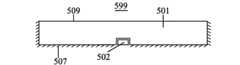
図5は、一実施形態における、組み込み光源と一緒に反射ミラーを持つ典型的なライトガイドシステム599のブロック図を示す。ミラーライトガイド501は、発光面509に面の反対側に反射されている。これは、前記表面上に隣接して配置、または光学的に結合、または置くことができるミラー507を使用して行う。光源502からの光はライトガイド501を通過して、偏差、散乱などのような様々な理由により、発光面509を終了してもよい。光の一部は、反対方向に移動し、発光面の方向に戻して反映されるミラー507を、達する光の一部は、反対方向に通過し、発光面の方向に戻して反映されるミラー507を、到達させてもよい。ミラー507は光学的にライトガイド501に結合、またはそれらの間のエアギャップまたは低屈折率材料で、別々に保たれてもよい。上記と同様に、表面の光ガイドの発光面に面の反対側は透明にすることができる。FIG. 5 shows a block diagram of an exemplary
一実施形態では、光源502は、発光面509に面の反対側に埋め込まれる。光源502は、ミラー507が配置される横に表面に埋め込むことができる。ミラー507は埋め込まれた光源502をそれ自体カバーしてもよいし、カバーしなくてもよい。それがカバーするときは、このライトガイドの非放射される側に向かって光の損失を防止する。それはカバーしない場合には、光源502の内部反射器は、また、ライトガイドの非放射される側に向かって移動する光をブロックしてもよい。In one embodiment, the
図6は、1つの実施形態における、埋め込まれた光源と一緒に反射ミラーを持つ典型的な光のガイドシステム699のブロック図を示す。点光源602は、ミラーライトガイド601内に埋め込まれる。点光源602をカバーするミラーライトガイド601のエッジ610がミラー608を使用して反射されている。光源602からの光はミラーライトガイド601の全体にわたって通過する。この光の一部は、エッジ610に向かって移動させてもよい。ミラー608は、この光をライトガイド601に戻って反映している。また、ミラー608(または光源602を直面する別のミラー)は、ミラーライトガイドの端610に入るように、光源602からの光を防ぐことができる。これは光がライトガイドを介してガイドされるように表面を介して入るように、光源602からの最大の光を支援する。FIG. 6 shows a block diagram of an exemplary
上記と同様に、ミラーは表面のライトガイドとそれに埋め込まれたミラーライトガイドとの間で使用することができる。Similar to the above, the mirror can be used between a surface light guide and a mirror light guide embedded in it.
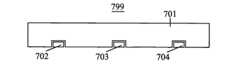
図7は、一実施形態における、複数の組み込み光源を持つ典型的な光のガイドシステム799のブロック図を示す。701ミラーライトガイドは、その中に埋め込まれたような702、703および704などの複数の点光源を持っている。ライトガイド内の複数の点光源の存在は、より多くの光をライトガイド内で使用できるようになる。従って、より強度の光源、またはより厚いあるいはよりかさばっていることなしで、その発光表面においてより大きい光源は作ることができる。同様に、面光源は、複数の組込み線形や点光源を持つことができる。FIG. 7 shows a block diagram of an exemplary
図8は、一実施形態における、複数の組み込み光源を持つ典型的な光のガイドシステム899のブロック図を示す。この実施形態では、このような802のような光源は、ライトガイド801の全幅をカバーする次元を持っている。FIG. 8 shows a block diagram of an exemplary
図9は、一実施形態における、複数の組み込みの光源を持つ典型的な光のガイドシステム999のブロック図を示す。この実施形態では、そのような902のような点光源はライトガイド901の幅内の異なる場所に埋め込まれている。FIG. 9 shows a block diagram of an exemplary
図10は、一実施形態における、光偏向表面レリーフ構造とその中に埋め込まれた光源を持つ典型的な光源システム1099のブロック図を示している。幾何学的形状、エッチングや色素沈着であってもよい偏向光の表面レリーフ構造1009は、ライトガイド1001内に通過する光源1002の光の一部をライトガイド1001の外に偏向する。FIG. 10 shows a block diagram of an exemplary
図11は、一実施形態における、典型的な光源システム1199のブロック図を示す。屈折、反射や散乱を使って光を偏向する光偏向粒子1109は、光ガイド1101内に通過する光源1102の光の一部をライトガイド1101の外に偏向する。光偏向粒子1109は例えば、フォトルミネセンスによって、光の波長を変更することができる。FIG. 11 shows a block diagram of an exemplary
図12は、一実施形態における、典型的な光源システム1299のブロック図を示す。光偏向粒子1209がライトガイド1201内に存在する。光偏向粒子1209が光源1202上記の領域1210より大きい濃度で存在する。光偏向ライトガイドの効果的な厚さは、光源1202(ライトガイド内で、光源1202の存在のため)の上に減少するため、光源1202の上の領域からの照明の低下を避けるように、光偏向粒子1209の濃度は、補正するためにその領域で増加する。FIG. 12 shows a block diagram of an exemplary
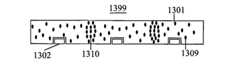
図13は、一実施形態における、典型的な光源システム1399のブロック図を示す。光偏向粒子1309は、光源に近い領域に比べて離れて光源(そのような光源1302など)からこの領域1310で高い濃度でライトガイド1301に存在する。これは、光源システム1399から発せられる光のより均一性を確保する。FIG. 13 shows a block diagram of an exemplary
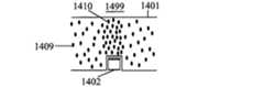
図14は、一実施形態における、典型的な光源システム1499のブロック図を示す。光偏向粒子1409は、光源1402上記の1401ライトガイドの領域1410に高濃度で存在する。ミラーは、光源1402からの直接光が光源システム1499から放射されないように、光源1402の上に配置される。FIG. 14 shows a block diagram of an exemplary
図15は、一実施形態における、典型的な光源システム1599のブロック図を示す。光偏向粒子1509は、光源1502などの組み込みの光源を持つライトガイド1501のスライス1512に低濃度で存在しないか、または存在する。光偏向粒子1509の高濃度は、光源1502からの光がライトガイド1501を入るからの開口1514の近くに存在していないので、光源1502の境界で、光源システム1599からの発光強度の連続性が存在する。光偏向粒子は、さらに離れて光源からの光ガイドのスライスに存在している。光偏向粒子が均一な濃度で、あるいは、様々な濃度で利用可能であってもよい、例えば、光源から離れてより高濃度で、そして光源に近いより低濃度であってもよい。FIG. 15 shows a block diagram of an exemplary
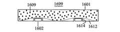
図16は、1つの実施形態における、典型的な光源システム1699のブロック図を示す。光偏向粒子1609は、光源1602からの光がライトガイド1601を入る所から開口1614に近い領域1612により低い濃度で存在しないか、または存在する。領域1612は光源1602から離れる方向へ先細りになる。FIG. 16 shows a block diagram of an exemplary
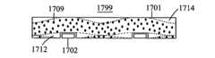
図17は、一実施形態における、典型的な光源システム1799のブロック図を示す。光偏向粒子1709は、光源1702からの光がライトガイド1701に入る開口近傍の領域1712により低い濃度で存在しないか、または存在する。領域1712は上、または下または両方から光源1702から先細りになってもよい。さらに、光偏向粒子1709の異なる濃度(より低い、より高いまたはなし)でそのような領域1714などの別の領域では、光ガイド1701の別の部分に存在してもよい。ライトガイドに沿って任意の位置での平均濃度は、必要な濃度になるように、放出された光の均一性、または必要な放射パターンに応じて放出された光が達成されるようにできる。例えば、領域1714は光源が埋め込まれている表面の反対側の近くに存在することができる、光源から離れて厚い、そして光源の近くに薄くなってもよい。FIG. 17 shows a block diagram of an exemplary
図18は、一実施形態における、典型的な光源システム1899のブロック図を示す。光偏向粒子1809は光源1802からの光がライトガイド1801を入る開口近傍の領域1812に低濃度で存在しないか、または存在する。領域1812は、光源1802から離れて、上記から先細りになる。光偏向粒子の異なる濃度を持つ領域1814などの別の領域では、存在してもよい。FIG. 18 shows a block diagram of an exemplary
図19は、一実施形態における、典型的な点光源1999のブロック図を示す。点光源1999ライトガイド(図示せず)の表面の開口部に向かって発光する。光源1999自体部分的または完全に透明または部分的にまたは完全に外部から入る光を反射してもよい。FIG. 19 shows a block diagram of an exemplary point
図20は、一実施形態における、典型的な点光源2099のブロック図を示す。点光源2099は、ミラー面2013年、そして発光ダイオード(LED)など1つ以上の光源2011を含むブロック2012で構成される。光源2011は、異なる方向に指していてもよい、すなわち、それらは互いに逆方向に移動する光を発散させてもよい。従って、光源2011の一つは、そのライトガイドの指示の特定のグループ内に通過する光を発散でき、光源2011の他は、方向の反対側のグループで移動する光を発散してもよい。FIG. 20 shows a block diagram of an exemplary point
ブロック2012は、光源2011の電気的接続を提供する1つまたは両方の導体として作用してもよい。電気的接続は、例えば、ワイヤボンディングの使用を通じてワイヤによって、または酸化インジウムスズ等の透明電極により提供されてもよい。
図21は、一実施形態における、典型的な点光源2199のブロック図を示す。点光源2199は、ミラー面2113を有するブロック2112、および複数の光源2111で構成されている。複数の光源は、すべての光の同じスペクトルを放射し、または別の光源は、異なるスペクトルの光を放射してもよい。例えば、いくつかの光源は青色光を他のが緑を、まだ他のが赤色を放射してもよい。赤、緑、青の光の成分は、ディスプレイ逆光に役立つ。赤、緑および青の量は、放射される光の色を変更するために変更されてもよい。複数の光源2111は二つの相反する方向のグループの光を調達する光源の2つのグループを含んでもよい。FIG. 21 shows a block diagram of an exemplary point
図22は、一実施形態における、典型的な点光源2299のブロック図を示す。光源2211が置かれる穴を囲むミラー2214は、光源2211からの光をライトガイドの開口部までガイドするのを支援する。ミラー2214は、さらにライトガイドから出る光をライトガイドへ送り返すのを支援する。FIG. 22 shows a block diagram of an exemplary point
図23は、一実施形態における、典型的な点光源2399のブロック図を示す。点光源2399は、同じまたは異なるスペクトルの透明なブロック1つ以上の光源2311を持っている2312で構成される。光源2311への電気的接続は、電線や導体で行うことができる、または透明なブロック2312はインジウムスズ酸化物や炭化ケイ素等の導電性基板であってもよい。このような窒化ガリウム、または様々な透明導電性酸化物のような基板を使用されてもよい。FIG. 23 shows a block diagram of an exemplary point
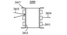
図24は、一実施形態における、反射点光源2499の線図である。典型的な光線2414が1つ以上の光源2411からの光源によって放射される。典型的な光線2415は、ライトガイド(図示せず)の開口部を出ており、点光源2499に向かって進んでいる。それは、ライトガイドに戻るには、ミラー面2413およびおそらくミラー面2417から反射し、それにより、光の利用効率を高める。FIG. 24 is a diagram of a reflective point
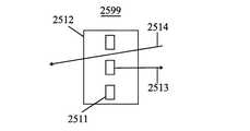
図25は、一実施形態における、透過点光源2599の線図である。典型的な光線2513が1つ以上の光源2511からの光源によって放射される。典型的な光線2514は、ライトガイドの開口部を出ました。それは、透明なブロック2512を通過して、ライトガイドの別の開口部に通過する。FIG. 25 is a diagram of a transmission
図26は、一実施形態における、点光源2699の線図である。LEDなどの光源となる光源2611は光2613を発する。光が点光源へのライトガイドを出る場合、その一部は、固有の反射率、界面反射、バック反射器、蛍光コーティング、拡散器コーティングあるいはLEDの電界発光とフォトルミネセンス材料により戻って反映される。FIG. 26 is a diagram of a
図27は、一実施形態における、点光源2799の線図である。光2713は、点光源2799へのライトガイドを出て、光源2711のうちの1つを打つ。低い波長の光が高い波長の光源を満たしている場合は、それを通過するか、またはバック反射器の内側で反映されてもよい。高い波長の光がより低い波長の光源を満たしている場合は、それを通過したり、反映されたり、またはそれより低い波長の光に変換されてもよく、放射されてもよい。FIG. 27 is a diagram of a
図28は、一実施形態における、光源のシステム2899の線図である。埋め込まれた光源2802からの光がライトガイド2801内にガイドされる。このような粒子2809のような散乱粒子をヒットすることもでき、光2812のような照明光を与えるためにライトガイド2801の外に散在されてもよく、またはそのような光2811、または光2813のようなライトガイド内でガイドされ続けてもよい。このような散乱光は、光2814などの照明光を与えるために、再び散乱されること、及び複数のそのような散乱後の光ガイド2801の外に散乱されてもよい。FIG. 28 is a diagram of a
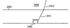
図29は、一実施形態における、光源のシステム2999の線図である。光源2902からの光2911は、照明光2912を形成するためにまっすぐにライトガイド2901を出る。ライトガイド2901の光入口と出口の表面が磨かれ、垂直に互いにであり、屈折率がより大きいかまたは最小屈折率に等しい場合、そして光のような直接的な放出が最小化されている、あるいは、そのような放射はない。FIG. 29 is a diagram of a
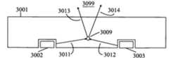
図30は、一実施形態における、光源のシステム3099の線図である。光偏向粒子3009は、方向3014の中への光源3002からの光3011および方向3013の中への光源3003からの光3012を偏向する。したがって、単一の光偏向粒子は多くの異なる光源からの光を偏向する。FIG. 30 is a diagram of a
図31は一つの実施の形態例によれば、光源システム3199を示す。シートライトガイド3101は、その中に線状光源3102を埋め込んでいる。線状光源3102は、既知の線状光源であってもよいし、彼らは多分、本発明に開示されているように、光偏向粒子を有するライトガイドへ光を放射する点光源を使用して作成される。点光源は、両端に存在するか、多分線状光源内に埋め込まれてもよい。シートライトガイド3101は、光偏向粒子を持っているので、シートのライトガイド3101内に移動する線状光源3102から放射された光は、シートのライトガイド3101から偏向される。FIG. 31 illustrates a
一実施形態では、線状光源3102の光偏向粒子の濃度は、それらが外部の光に対して透明になるように、疎に保つことができる。このように、シートのライトガイド内を移動する光が線状光源を入ると、それは再びシートのライトガイドに入る。In one embodiment, the concentration of light deflecting particles of the linear
図32は、一つの実施形態における、光源のシステム3299の側面図を示す。線状光源3202は、光偏向粒子を持つシートライトガイド3201内に埋め込まれている。本特許で開示された実施形態は、点光源を有する線状ライトガイドだけでなく、線状光源を有するシートライトガイドに適用される。FIG. 32 illustrates a side view of a
図33は、一つの実施形態における、光源のシステム3399の底面図を示す。光偏向粒子を有するシートライトガイド3301は、線状光源3302内に組み込まれている。線状光源3302は、組み込みの点光源3303、及び光偏向粒子3309を有する線状のライトガイドである。このように大規模な表面を均一に(または優先)、効率的な方法で、薄い装置に点光源を使用して明るく照らされてもよい。FIG. 33 shows a bottom view of a
一実施形態では、それぞれの線状光源、または光源システム3399内の各点光源は、オンオフになっているか、個別に薄暗くすることができる。特定の点光源を点けると、表面を均一には明るくしないが、それは特定の領域でより多くのそれを明るくする。例えば、点光源3304を明るくすると、他の場所からよりも、エリア3310から放出されるより多くの光が発生する。光源システム3399は、フラットパネルディスプレイのバックライトに使用されている場合、これは選択的に明るいまたは暗いオブジェクトが存在するスクリーンの部分を明るくしたり暗くするために使用することができる、それにより、より優れたエネルギー効率と優れたコントラストを与える。それぞれの点光源は、個別の色のための個別のエミッターを持っており、例えば、赤、緑、青の色のため、または交互に、いくつかの点光源にはいくつかの色のエミッターがあってもよく、また、他のものには他の色のエミッターがあってもよい。そのような場合では、点光源の各エミッタは、明るさだけでなく、特定の領域の色も制御できるように、個々に明るくまたは薄暗くなってもよい。バックライトとして使用する場合、本発明は、より多くの色の鮮やかさと、より効率を与え、さらに正確な色を生成するディスプレーパネルで変更する適切な明るさだけでなく、適切な色を生成する。In one embodiment, each linear light source, or each point light source in the
図34は、一実施形態における、光源システム3499を示す。ライトガイド3401は、光源3402、及び光偏向粒子を埋め込まれている。別のライトガイド3411は、光源3412、及び光偏向粒子を埋め込まれている。これらのライトガイドは、明るい光源を与えるために、並んで配置される。ライトガイドは単一の光のガイドを作成するには、光学接着剤を使ってまた、融合させることまたは光学的に結合してもよい。FIG. 34 illustrates a
図35は、一実施形態における、光源システム3599を示す。光源システム3599は、光偏向粒子3509と埋め込まれた光源3502を有するライトガイド3501である。埋め込まれた光源は、光ガイド3501の一方の表面付近に配置されてもよい、または図示されているようにそれらは、ライトガイド3501のバルク内部に埋め込むことができる。ミラーは、埋め込み光源3502に発生して埋め込まれた光が直接にライトガイド3501を出ることを防止するため、およびライトガイド3501に移動する光が光源3502に入ることを防止するために、光源3502の上下に配置されている。偏向された光3511、3512および3513は、ライトガイド3501の両方向に向かって放射される。その光は一方向にのみ放出されるように、一実施形態では、ミラーは、ライトガイド3501の一方の側に配置されている。一実施形態では、光偏向粒子の濃度は、主に偏向することなく外部の光3514がライトガイド3501を通過するように十分に低く保たれている。FIG. 35 illustrates a
図36は、一実施形態における、モジュール式の光源システム3699を示す。光源システム3699は、エンドツーエンドに配置などのモジュール3650のような多くのモジュールを備える。モジュール3650のようなモジュールは、本明細書で説明したように、光偏向粒子、および1つ以上の埋め込まれた光源を含む光ガイドを持つ光源システムである。光源システム3699の末端にモジュール3651の壁3621は、ミラー3622を持って、その光が無駄になることはない。壁3623のような二つのモジュール間の壁には、ミラーがあってもよいし、なくてもよい。ミラーが用意されていない場合、ライトは1つのモジュールから次のものまで混ぜて、良好な発光の継続性を与える。一実施形態では、部分的なミラーは、壁の下側部分に設けられている。典型的な光線3606は、光源3602から放出され、ミラー3622に打ち、モジュール3651によってガイドされ、その後別のモジュール3650に入って、光源システム3699によって放出される粒子を偏向光によって偏向される。任意の数のそのようなモジュールは、必要なサイズの光源を与えるために一緒に置くことができ、それにより、組み合わせることができる製造モジュールに異なるサイズの光源の製造を簡素化する。モジュールには、相互モジュラー壁や他の場所で位置することができる圧入ラッチまたはノッチのような簡単にお互いにそれらを適合させるために使用できる機械的な構造であってもよい。モジュールは、融合または互いに接着されてもよい。一実施形態では、すべてのモジュールがまっすぐに埋め込まれた光源上の高濃度の可能性を除いて、埋め込み光源から離れて、より多くの濃度を持つ同じ濃度の変化のプロファイルを持っている。FIG. 36 illustrates a modular
Claims (7)
Translated fromJapaneseApplications Claiming Priority (3)
| Application Number | Priority Date | Filing Date | Title |
|---|---|---|---|
| IN1194MU2009 | 2009-05-06 | ||
| IN1194/MUM/2009 | 2009-05-06 | ||
| PCT/US2010/033938WO2010129815A2 (en) | 2009-05-06 | 2010-05-06 | Light guide with embedded light sources |
Publications (1)
| Publication Number | Publication Date |
|---|---|
| JP2012526363Atrue JP2012526363A (en) | 2012-10-25 |
Family
ID=43050884
Family Applications (1)
| Application Number | Title | Priority Date | Filing Date |
|---|---|---|---|
| JP2012509985APendingJP2012526363A (en) | 2009-05-06 | 2010-05-06 | Light guide with built-in light source |
Country Status (4)
| Country | Link |
|---|---|
| US (1) | US20120051093A1 (en) |
| JP (1) | JP2012526363A (en) |
| CN (1) | CN102483215A (en) |
| WO (1) | WO2010129815A2 (en) |
Cited By (1)
| Publication number | Priority date | Publication date | Assignee | Title |
|---|---|---|---|---|
| JP2023003825A (en)* | 2021-06-24 | 2023-01-17 | 大日本印刷株式会社 | Surface light source device and display device |
Families Citing this family (17)
| Publication number | Priority date | Publication date | Assignee | Title |
|---|---|---|---|---|
| US8876354B2 (en)* | 2009-05-06 | 2014-11-04 | Udayan Kanade | Light source comprising light deflecting particles |
| JP5670794B2 (en)* | 2011-03-28 | 2015-02-18 | 富士フイルム株式会社 | Surface lighting device |
| TWI484264B (en)* | 2011-05-04 | 2015-05-11 | Ultra - thin front light module | |
| EP2541534A1 (en) | 2011-07-01 | 2013-01-02 | Koninklijke Philips Electronics N.V. | Light output device and method of manufacture |
| KR20130078785A (en)* | 2011-12-30 | 2013-07-10 | 코오롱인더스트리 주식회사 | Light guide plate and method for preparing the same |
| US20250075868A1 (en)* | 2013-01-30 | 2025-03-06 | Cree Lighting Usa Llc | Lighting Devices Having Optical Waveguides for Controlled Light Distribution |
| CN108594342B (en) | 2013-12-19 | 2020-09-25 | 康宁股份有限公司 | Textured Surfaces for Display Applications |
| KR102264379B1 (en)* | 2014-02-05 | 2021-06-15 | 엘지이노텍 주식회사 | Optical device and lighting device using the same |
| CN104849793A (en) | 2014-02-19 | 2015-08-19 | 广州奥翼电子科技有限公司 | Electronic paper display light guide plate and electronic paper display |
| CN104329612A (en)* | 2014-10-27 | 2015-02-04 | 广东凯西欧照明有限公司 | Point-light-source panel light |
| EP4325264A3 (en) | 2016-04-13 | 2024-05-22 | TactoTek Oy | Illuminated multilayer structure with embedded light sources |
| FR3070070A1 (en)* | 2017-08-14 | 2019-02-15 | Koito Manufacturing Co., Ltd. | ROD-SHAPED LIGHT GUIDE AND VEHICLE LAMP |
| CN207133458U (en)* | 2017-09-19 | 2018-03-23 | 北京京东方显示技术有限公司 | Light guide plate, backlight module and display device |
| TWI666495B (en)* | 2018-03-06 | 2019-07-21 | 友達光電股份有限公司 | Backlight module |
| CN111367122A (en)* | 2020-04-03 | 2020-07-03 | 深圳市隆利科技股份有限公司 | Light guide LED lamp panel |
| CN111323967A (en)* | 2020-04-03 | 2020-06-23 | 深圳市隆利科技股份有限公司 | Surface light source backlight device |
| TWI766713B (en) | 2021-06-03 | 2022-06-01 | 元太科技工業股份有限公司 | Light source module |
Family Cites Families (6)
| Publication number | Priority date | Publication date | Assignee | Title |
|---|---|---|---|---|
| AU4409496A (en)* | 1994-11-29 | 1996-06-19 | Precision Lamp, Inc. | Edge light for panel display |
| KR100638874B1 (en)* | 2005-07-06 | 2006-10-27 | 삼성전기주식회사 | A light source-light guide plate structure of a backlight device having an LED light source inserted into the light guide plate and a backlight device including the same |
| US20070086179A1 (en)* | 2005-10-14 | 2007-04-19 | Radiant Opto-Electronics Corporation | Light mixing plate and direct backlight module |
| TWI330288B (en)* | 2006-01-17 | 2010-09-11 | Au Optronics Corp | Backlight module |
| KR101234100B1 (en)* | 2006-11-07 | 2013-02-19 | 삼성디스플레이 주식회사 | Lamp socket and back light assembly having the same |
| KR20090024014A (en)* | 2007-09-03 | 2009-03-06 | 박휴완 | LGP Illuminator |
- 2010
- 2010-05-06JPJP2012509985Apatent/JP2012526363A/enactivePending
- 2010-05-06WOPCT/US2010/033938patent/WO2010129815A2/enactiveApplication Filing
- 2010-05-06CNCN2010800312111Apatent/CN102483215A/enactivePending
- 2010-05-06USUS13/319,095patent/US20120051093A1/ennot_activeAbandoned
Cited By (2)
| Publication number | Priority date | Publication date | Assignee | Title |
|---|---|---|---|---|
| JP2023003825A (en)* | 2021-06-24 | 2023-01-17 | 大日本印刷株式会社 | Surface light source device and display device |
| JP7658191B2 (en) | 2021-06-24 | 2025-04-08 | 大日本印刷株式会社 | Surface light source device and display device |
Also Published As
| Publication number | Publication date |
|---|---|
| US20120051093A1 (en) | 2012-03-01 |
| WO2010129815A2 (en) | 2010-11-11 |
| CN102483215A (en) | 2012-05-30 |
| WO2010129815A3 (en) | 2011-02-03 |
Similar Documents
| Publication | Publication Date | Title |
|---|---|---|
| JP2012526363A (en) | Light guide with built-in light source | |
| KR100499133B1 (en) | Backlight unit | |
| JP5420415B2 (en) | Flat thin LED lighting device | |
| JP4263611B2 (en) | Compact lighting system and display device | |
| KR100506092B1 (en) | Light guide panel of edge light type backlight apparatus and edge light type backlight apparatus using the same | |
| US7549782B2 (en) | Semiconductor light source configured as a light tube | |
| JP4273002B2 (en) | Compact lighting system and display device | |
| JP4874793B2 (en) | Luminous body | |
| JP5384347B2 (en) | Lighting system, lighting fixture and display device | |
| US8118467B2 (en) | Light guide plate and edge-lighting type backlight module | |
| JP5323274B2 (en) | Surface light source device and liquid crystal display device | |
| KR20080031573A (en) | Zen light source using point light source | |
| CN100416317C (en) | illuminator | |
| CN104822986B (en) | Use the light emitting device of light guide | |
| WO2013051296A1 (en) | Collected linear illumination device and driving method therefor, and light fixture | |
| CN109661541B (en) | Indirect lighting device | |
| CN105992911A (en) | Optical element and lighting device with an optical element | |
| US12281774B2 (en) | Vehicle lamp having excitation light source, light conversion unit, and red lens | |
| JP5119379B2 (en) | Surface illumination light source device and surface illumination device | |
| WO2014203725A1 (en) | Lighting apparatus | |
| JP4000444B2 (en) | Surface lighting device | |
| JP2010103060A (en) | Display device | |
| EP3108176B1 (en) | Led luminaire | |
| CN106066554A (en) | A kind of backlight module and display device | |
| JP2005302659A (en) | Illumination device and display device including the same |