JP2012526280A - Photosensitive device having color sensor and clear sensor for infrared ray removal - Google Patents
Photosensitive device having color sensor and clear sensor for infrared ray removalDownload PDFInfo
- Publication number
- JP2012526280A JP2012526280AJP2012509847AJP2012509847AJP2012526280AJP 2012526280 AJP2012526280 AJP 2012526280AJP 2012509847 AJP2012509847 AJP 2012509847AJP 2012509847 AJP2012509847 AJP 2012509847AJP 2012526280 AJP2012526280 AJP 2012526280A
- Authority
- JP
- Japan
- Prior art keywords
- light
- sensor
- color
- filter
- intensity
- Prior art date
- Legal status (The legal status is an assumption and is not a legal conclusion. Google has not performed a legal analysis and makes no representation as to the accuracy of the status listed.)
- Granted
Links
- 230000000903blocking effectEffects0.000claimsabstractdescription9
- 238000001514detection methodMethods0.000claimsdescription11
- 230000003993interactionEffects0.000claimsdescription5
- 239000000758substrateSubstances0.000claimsdescription5
- 230000005540biological transmissionEffects0.000claimsdescription4
- 239000011248coating agentSubstances0.000claimsdescription3
- 238000000576coating methodMethods0.000claimsdescription3
- 239000011521glassSubstances0.000claimsdescription3
- 230000001413cellular effectEffects0.000description12
- 230000006870functionEffects0.000description12
- 238000010586diagramMethods0.000description6
- 238000000034methodMethods0.000description6
- 230000003287optical effectEffects0.000description6
- 238000006243chemical reactionMethods0.000description5
- 239000003086colorantSubstances0.000description5
- 238000004891communicationMethods0.000description5
- 238000004519manufacturing processMethods0.000description5
- 230000035945sensitivityEffects0.000description5
- 230000005236sound signalEffects0.000description5
- 238000004364calculation methodMethods0.000description4
- 238000012545processingMethods0.000description4
- 230000004044responseEffects0.000description4
- 230000000694effectsEffects0.000description3
- 238000002834transmittanceMethods0.000description3
- 238000005286illuminationMethods0.000description2
- 239000000463materialSubstances0.000description2
- 239000004065semiconductorSubstances0.000description2
- 230000011664signalingEffects0.000description2
- 230000009471actionEffects0.000description1
- 230000003321amplificationEffects0.000description1
- 238000013475authorizationMethods0.000description1
- 230000008901benefitEffects0.000description1
- 230000003139buffering effectEffects0.000description1
- 230000000295complement effectEffects0.000description1
- 230000003750conditioning effectEffects0.000description1
- 238000004146energy storageMethods0.000description1
- 238000005516engineering processMethods0.000description1
- 238000002329infrared spectrumMethods0.000description1
- 238000005259measurementMethods0.000description1
- 230000007246mechanismEffects0.000description1
- 229910044991metal oxideInorganic materials0.000description1
- 150000004706metal oxidesChemical class0.000description1
- 238000012986modificationMethods0.000description1
- 230000004048modificationEffects0.000description1
- 238000003199nucleic acid amplification methodMethods0.000description1
- 230000005855radiationEffects0.000description1
- 230000009467reductionEffects0.000description1
- 239000007787solidSubstances0.000description1
- 230000003595spectral effectEffects0.000description1
- 238000001228spectrumMethods0.000description1
- 238000001429visible spectrumMethods0.000description1
Images


Classifications
- G—PHYSICS
- G01—MEASURING; TESTING
- G01J—MEASUREMENT OF INTENSITY, VELOCITY, SPECTRAL CONTENT, POLARISATION, PHASE OR PULSE CHARACTERISTICS OF INFRARED, VISIBLE OR ULTRAVIOLET LIGHT; COLORIMETRY; RADIATION PYROMETRY
- G01J1/00—Photometry, e.g. photographic exposure meter
- G01J1/10—Photometry, e.g. photographic exposure meter by comparison with reference light or electric value provisionally void
- G01J1/20—Photometry, e.g. photographic exposure meter by comparison with reference light or electric value provisionally void intensity of the measured or reference value being varied to equalise their effects at the detectors, e.g. by varying incidence angle
- G01J1/28—Photometry, e.g. photographic exposure meter by comparison with reference light or electric value provisionally void intensity of the measured or reference value being varied to equalise their effects at the detectors, e.g. by varying incidence angle using variation of intensity or distance of source
- G01J1/30—Photometry, e.g. photographic exposure meter by comparison with reference light or electric value provisionally void intensity of the measured or reference value being varied to equalise their effects at the detectors, e.g. by varying incidence angle using variation of intensity or distance of source using electric radiation detectors
- G01J1/32—Photometry, e.g. photographic exposure meter by comparison with reference light or electric value provisionally void intensity of the measured or reference value being varied to equalise their effects at the detectors, e.g. by varying incidence angle using variation of intensity or distance of source using electric radiation detectors adapted for automatic variation of the measured or reference value
- G—PHYSICS
- G01—MEASURING; TESTING
- G01J—MEASUREMENT OF INTENSITY, VELOCITY, SPECTRAL CONTENT, POLARISATION, PHASE OR PULSE CHARACTERISTICS OF INFRARED, VISIBLE OR ULTRAVIOLET LIGHT; COLORIMETRY; RADIATION PYROMETRY
- G01J1/00—Photometry, e.g. photographic exposure meter
- G01J1/10—Photometry, e.g. photographic exposure meter by comparison with reference light or electric value provisionally void
- G01J1/16—Photometry, e.g. photographic exposure meter by comparison with reference light or electric value provisionally void using electric radiation detectors
- G01J1/1626—Arrangements with two photodetectors, the signals of which are compared
- G—PHYSICS
- G01—MEASURING; TESTING
- G01J—MEASUREMENT OF INTENSITY, VELOCITY, SPECTRAL CONTENT, POLARISATION, PHASE OR PULSE CHARACTERISTICS OF INFRARED, VISIBLE OR ULTRAVIOLET LIGHT; COLORIMETRY; RADIATION PYROMETRY
- G01J1/00—Photometry, e.g. photographic exposure meter
- G01J1/42—Photometry, e.g. photographic exposure meter using electric radiation detectors
- G01J1/4204—Photometry, e.g. photographic exposure meter using electric radiation detectors with determination of ambient light
- G—PHYSICS
- G01—MEASURING; TESTING
- G01J—MEASUREMENT OF INTENSITY, VELOCITY, SPECTRAL CONTENT, POLARISATION, PHASE OR PULSE CHARACTERISTICS OF INFRARED, VISIBLE OR ULTRAVIOLET LIGHT; COLORIMETRY; RADIATION PYROMETRY
- G01J1/00—Photometry, e.g. photographic exposure meter
- G01J1/02—Details
- G01J1/04—Optical or mechanical part supplementary adjustable parts
- G01J1/0488—Optical or mechanical part supplementary adjustable parts with spectral filtering
Landscapes
- Physics & Mathematics (AREA)
- General Physics & Mathematics (AREA)
- Spectroscopy & Molecular Physics (AREA)
- Life Sciences & Earth Sciences (AREA)
- Sustainable Development (AREA)
- Photometry And Measurement Of Optical Pulse Characteristics (AREA)
- Controls And Circuits For Display Device (AREA)
- Spectrometry And Color Measurement (AREA)
- Telephone Function (AREA)
Abstract
Translated fromJapaneseDescription
Translated fromJapanese本発明の実施形態は、一体型の周囲光センサ(ALS)を有するポータブル電子装置に係る。他の実施形態についても説明する。 Embodiments of the present invention relate to portable electronic devices having an integrated ambient light sensor (ALS). Other embodiments will also be described.
多機能スマートホン、デジタルメディアプレーヤ、専用デジタルカメラ及びナビゲーション装置のようなポータブル電子装置は、種々の照明環境のもとで使用できるディスプレイスクリーンを有している。このような装置は、その外部の直接的環境における可視光の現在レベルの指示を(リアルタイムで)与えることのできる機能を一体化している。これは、周囲光センサ機能(又はALS)と称される。このALSは、(現在周囲光レベルに基づいて)読み易さ又はバッテリエネルギー保存のためにディスプレイスクリーンの輝度を自動的に管理する等の用途に使用することができる。 Portable electronic devices such as multi-function smart phones, digital media players, dedicated digital cameras, and navigation devices have display screens that can be used in a variety of lighting environments. Such a device integrates a function that can give (in real time) an indication of the current level of visible light in its external direct environment. This is referred to as the ambient light sensor function (or ALS). This ALS can be used for applications such as automatically managing display screen brightness for readability or battery energy storage (based on current ambient light levels).
最近、内蔵型のソリッドステート光センサを、入射する周囲可視光の非常に正確な測定値をリアルタイムで与える関連アナログ及びデジタル回路と一緒に有する進歩型の消費者グレードのALS集積回路(IC)装置が開発された。これらのIC装置は、ほとんどの部分が相補的金属酸化物半導体(CMOS)製造プロセス技術に基づいて製造されたものである。 Recently, an advanced consumer-grade ALS integrated circuit (IC) device that has a self-contained solid-state light sensor along with related analog and digital circuits that provide a very accurate measurement of incident ambient visible light in real time. Was developed. Most of these IC devices are manufactured based on complementary metal oxide semiconductor (CMOS) manufacturing process technology.
多数の典型的なCMOS光センサ構造体(例えば、CMOSホトダイオード)の応答は、可視光含有物ではなく、赤外線(IR)含有物によって支配される。これは、ある人為的な照明環境のもとで問題を招く。例えば、CMOSベースのALS装置は、おそらく、白熱灯で照明されたときは、蛍光灯に比して、その周囲環境が「明るい」ことを指示する。というのは、白熱灯の照明は、例えば、蛍光灯の照明に比してIR含有物が非常に多く、そしてIRが優勢である照明状態と可視光が優勢である照明状態との間をセンサが区別できないためである。この問題を軽減する助けとして、IR阻止フィルタ(IRカットフィルタ)をセンサの前に配置し、IR含有物に対するセンサの出力の感度を下げることができる。 The response of many typical CMOS photosensor structures (eg, CMOS photodiodes) is dominated by infrared (IR) inclusions rather than visible light inclusions. This leads to problems under certain artificial lighting environments. For example, a CMOS-based ALS device probably indicates that its ambient environment is “bright” when illuminated with an incandescent lamp, as compared to a fluorescent lamp. This is because incandescent lighting, for example, is much more IR-containing than fluorescent lighting, and it is a sensor between the illumination state where the IR is dominant and the illumination state where the visible light is dominant. This is because cannot be distinguished. To help alleviate this problem, an IR blocking filter (IR cut filter) can be placed in front of the sensor to reduce the sensitivity of the sensor output to IR inclusions.
実際には、もちろん、IRカットフィルタは、フィルタを通過してセンサによって検出される著しいIR含有物がまだ存在するという点で理想的ではない。このようなIR漏洩は、比較的僅かであるが、次の状況においてはALSにとって著しく大きなものとなる。ポータブル電子装置の光透過カバーが、物理的開口のない比較的滑らか又は均一な前面を有する場合について考える。装置の外部の周囲光レベルを感知するためにALSチップがカバーの下に配置される。ある場合には、(例えば、審美的な理由で)前面が外部から暗く見えるようにすることが望まれる。これを達成するため、カバーの前面に均一な暗い色(例えば、ブラック)を与えるIR透過インクの層をカバーの後ろ側に付着することができる。しかしながら、このIRインク層は、非常に僅かな可視光含有物が通過してその下のセンサに達するのを許す(例えば、約5%以下の透過)。これは、(IRカットフィルタを使用してIR含有物の減少が達成されるのも関わらず)センサの出力信号において可視光からIRを区別する能力を低下させる。 In practice, of course, an IR cut filter is not ideal in that there is still significant IR content passing through the filter and detected by the sensor. Such IR leakage is relatively small, but becomes significant for ALS in the following situations: Consider the case where the light transmissive cover of a portable electronic device has a relatively smooth or uniform front surface without physical openings. An ALS chip is placed under the cover to sense ambient light levels outside the device. In some cases, it may be desirable to allow the front surface to appear dark from the outside (eg, for aesthetic reasons). To accomplish this, a layer of IR transmissive ink that provides a uniform dark color (eg, black) on the front of the cover can be deposited on the back side of the cover. However, this IR ink layer allows very little visible light content to pass through to the underlying sensor (eg, less than about 5% transmission). This reduces the ability to distinguish IR from visible light in the sensor output signal (even though IR reduction is achieved using an IR cut filter).
本発明の実施形態は、ポータブル電子装置において周囲光センサ(ALS)の機能を遂行できる光感知装置である。この装置の要素は、光経路において可視光を阻止する第1のフィルタと、光経路において第1のフィルタの後に光を検出するセンサのセットとを含む。これらセンサは、少なくとも、第1のカラーセンサ及びクリアセンサを含む。又、装置は、光経路における可視光の強度の尺度を計算する光強度計算器も有する。この計算は、第1のカラーセンサの出力信号と、クリアセンサの出力信号との間の差に基づく。換言すれば、周囲光レベルの尺度は、少なくとも1つのカラーチャンネル及びクリアチャンネルの差に基づいて計算される。このようにして、光経路におけるIR含有物が効果的に打ち消される(カラーセンサ及びクリアセンサの出力信号間の差を考慮したとき)。 Embodiments of the present invention are optical sensing devices that can perform the function of an ambient light sensor (ALS) in a portable electronic device. The elements of the apparatus include a first filter that blocks visible light in the light path and a set of sensors that detect light after the first filter in the light path. These sensors include at least a first color sensor and a clear sensor. The apparatus also has a light intensity calculator that calculates a measure of the intensity of visible light in the light path. This calculation is based on the difference between the output signal of the first color sensor and the output signal of the clear sensor. In other words, the measure of ambient light level is calculated based on the difference between at least one color channel and the clear channel. In this way, IR inclusions in the light path are effectively canceled (when considering the difference between the output signals of the color sensor and the clear sensor).
別の実施形態では、(周囲光レベルを表す)光強度の計算は、1つのカラーチャンネルとクリアチャンネルとの間の差を使用するだけではなく、更に別の差の量、即ち別のカラーチャンネルとクリアチャンネルとの間の差も使用する。このような技術は、第1及び第2のカラーセンサが、例えば、各々、従来のRGB光センサの一部分として容易に入手できる赤色及び青色センサであるときに有用である。このシナリオのもとで、強度計算器は、シアン及びイエローの値を各々表す少なくとも2つのクリア/カラー差を緑色値に変換する。次いで、この緑色値を使用して、光強度の直接的な尺度であるルクス値を計算することができる。 In another embodiment, the calculation of the light intensity (representing the ambient light level) not only uses the difference between one color channel and the clear channel, but also another amount of difference, ie another color channel. And the difference between the clear channel. Such a technique is useful when the first and second color sensors are, for example, red and blue sensors, each readily available as part of a conventional RGB light sensor. Under this scenario, the intensity calculator converts at least two clear / color differences, each representing cyan and yellow values, to green values. This green value can then be used to calculate a lux value, which is a direct measure of light intensity.
上述した概要は、本発明のあらゆる態様を余すところなく含むものではない。本発明は、以上に概要を述べた種々の態様の全ての適当な組み合わせ、並びに以下の詳細な説明に開示され且つ特許請求の範囲に特に指摘されたものから実施できるあらゆるシステム及び方法を包含することが意図される。このような組み合わせは、以上の概要に特に述べなかった特定の効果を有する。 The above summary is not exhaustive of all aspects of the invention. The present invention encompasses all suitable combinations of the various aspects outlined above, as well as any system and method that can be implemented from what is disclosed in the following detailed description and specifically pointed out in the claims. Is intended. Such a combination has specific effects not specifically mentioned in the above summary.
本発明の実施形態は、同様の要素が同じ参照番号で示された添付図面に一例として示されるが、これに限定されない。この開示における本発明の「一」又は「1つの」実施形態とは、必ずしも同じ実施形態ではなく、少なくとも1つを意味することに注意されたい。 Embodiments of the present invention are illustrated by way of example in the accompanying drawings, in which like elements are designated with the same reference numerals, but are not limited thereto. It should be noted that “one” or “one” embodiment of the present invention in this disclosure refers to at least one, not necessarily the same embodiment.
添付図面を参照して本発明の幾つかの実施形態を以下に説明する。実施形態において述べる部品の形状、相対的な位置、及び他の観点が明確に定義されないときには、本発明の範囲は、単なる例示に過ぎない図示された部品のみに限定されない。又、多数の細部について述べるが、本発明のある実施形態は、これら細部がなくても実施できることを理解されたい。他の点について、良く知られた回路、構造及び技術は、本説明の理解を不明瞭にしないために、詳細には示さない。 Several embodiments of the present invention will be described below with reference to the accompanying drawings. When the shapes, relative positions, and other aspects of the parts described in the embodiments are not clearly defined, the scope of the present invention is not limited to the illustrated parts, which are merely examples. Also, while numerous details are set forth, it should be understood that certain embodiments of the invention may be practiced without these details. In other instances, well-known circuits, structures and techniques have not been shown in detail in order not to obscure the understanding of this description.
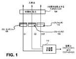
図1を参照すれば、本発明の一実施形態による周囲光センサ(ALS)のブロック図が示されている。可視光含有物のレベルを決定するために感知されるべき入射光は、その下の光センサ106、108、110のセットに到達する前に可視光の含有物を阻止する第1フィルタ104を通る光経路をたどる。この第1フィルタ104は、その下にあるセンサ電子装置は本質的に見えないように隠し、それ以外はフィルタ104の上から肉眼で見えるようにする。これは、例えば、均一又は滑らかで且つ暗い見掛けがフィルタ104上に望まれる場合には審美的な機能を果たす。これは、可視光を阻止するIR透過インクの層が存在する基板の一部分としてフィルタ104を構成することにより達成される。 Referring to FIG. 1, a block diagram of an ambient light sensor (ALS) according to one embodiment of the present invention is shown. Incident light to be sensed to determine the level of visible light inclusions passes through a
もちろん、フィルタ104は、可視光を阻止すると言えるが、実際的な意味では、全ての可視光を「完全に」阻止するのではない。例えば、1つの具現化において、フィルタ104は、可視光スペクトルの約2%−5%及びIRスペクトルの90%以上を透過する。可視光含有物に対する透過率がそれより非常に高い場合には、フィルタ104は、上から充分に暗い見掛けを与えない(その下のセンサ電子装置がかなり見える)。他方、可視光含有物に対する透過がかなり低い(例えば、2%より著しく低い)場合には、充分な量の可視光が光センサ106−110に到達しない。フィルタ104の透過は、可視光含有物に対する光センサ106−110の感度に基づき、IR含有物(これも入射光に存在する)に対するそれらの感度に対して、選択されねばならない。 Of course, although the
カラー光センサ106、108の出力は、他のものではなく、特定の可視カラーの感知された光強度を表す信号を与える。別の見方をすると、カラー光センサは、特定の可視カラーを検出するように同調された光感知手段である。対照的に、クリアセンサ110は、複数の可視カラーの感知された光強度を表す信号を出力する。特に、クリアセンサは、可視スペクトル全体にわたり感知された光強度を与える信号を出力する。 The output of the
光センサ106−110は、ソリッドステートCMOSセンサであるか、又は可視光に対して充分な感度を有する他の適当なセンサである。これらは、CMOS製造プロセス、或いは他の適当な半導体又は集積回路製造プロセスで組み込まれるホトダイオード及びホトトランジスタを含む。少なくとも1つのカラーセンサ106及び少なくとも1つのクリアセンサ110があるが、図1に示した実施形態は、付加的なカラーセンサ108を有する。1つの具現化において、カラーセンサ106、108の各々は、各光検出素子をカバーする異なるカラーフィルタ素子を有する。換言すれば、カラーセンサ106、108の各々は、異なるカラーの可視光を感知するように同調される。カラーセンサ106、108とは対照的に、クリアセンサ110は、単一のカラーだけではなく、広い範囲の異なる可視カラーの感知された光強度を指示する信号を出力する。 Photosensors 106-110 are solid state CMOS sensors or other suitable sensors that have sufficient sensitivity to visible light. These include photodiodes and phototransistors that are incorporated in CMOS manufacturing processes, or other suitable semiconductor or integrated circuit manufacturing processes. Although there is at least one
更に、カラーセンサ106、108の光検出素子は、クリアセンサ110の光検出素子と電気的にマッチングされる。換言すれば、カラーセンサ106が赤色センサである場合に、入射光が赤色含有物しか含まなければ、カラーセンサ106の出力信号は、クリアセンサ110からの出力信号に非常に近いものとなる。同様に、カラーセンサ108が青色センサでありそして入射光が青色含有物しか含まない場合には、カラーセンサ108及びクリアセンサ110からの出力信号が非常に近いものとなる。更に、センサ106−110の各々のIR応答も、電気的にマッチングしなければならない(これは、以下の式においてIR含有物のより正確な打ち消しを可能にする)。光検出素子の電気的なマッチングは、光検出素子を互いにできるだけ接近して配置したり、同じ製造プロセス操作を使用してそれらを同じ基板に構築したり、同じ物理的寸法及び回路トポロジーを有するようにそれらを設計したりする、等の異なる製造技術を使用して、達成される。 Further, the light detection elements of the
又、図1の周囲光センサは、センサ106−110が存在する光経路における可視光の強度の尺度を計算する光強度計算器112も備えている。図1の実施形態の場合に、計算は、少なくとも2つの差、即ちクリアセンサの出力信号と、第1のカラーセンサ106の出力信号との間の差、及びクリアセンサの出力と、第2のカラーセンサ108の出力との間の差に基づいて行われる。これは、数学的形態では、次の関係として表される。
強度∝(クリア−k1*C1)及び(クリア−k2*C2) [式1]
但し、k1及びk2は、前記式のカッコ内の各項が光経路におけるIR含有物の作用の充分良好な打ち消しを生じるように、校正手順中に選択されねばならない比例定数又はミスマッチ定数である。例えば、定数k1及びk2は、(フィルタ104の後の)入射光における同じIR含有物に対する各応答の項においてカラーセンサ106、108とクリアセンサ110との間のミスマッチの作用を除去する上で助けとなる。The ambient light sensor of FIG. 1 also includes a
Strength ∝ (clear -k1 * C1 ) and (clear -k2 * C2 ) [Formula 1]
Where k1 and k2 are proportionality constants or mismatch constants that must be selected during the calibration procedure so that each term in the parentheses in the above equation yields a sufficiently good cancellation of the action of IR inclusions in the optical path. is there. For example, the constants k1 and k2 eliminate the effects of mismatch between the
以下に更に述べるように、光強度計算器112は、例えば、センサ106−110からの各アナログ出力信号をデジタル形態へ変換するアナログ/デジタルコンバータと、その後に、上述した数学式を解くハードワイヤードロジック又はプログラム型プロセッサが続く形態で具現化される。これは、ALSが、図1に示した素子を一体化できるポータブル電子装置の外部の周囲光レベルの強度の尺度をリアルタイムで計算できるようにする。それにより得られる周囲光強度の尺度は、例えば、読み易さ及びバッテリエネルギー節約の目的でディスプレイスクリーンの輝度を制御することを含む、ポータブル電子装置で実行される種々のアプリケーションにより使用される。 As described further below, the
上述したように、光強度の計算は、それに代わって、単一のクリア/カラー差に基づくものでもよい。例えば、単一のマゼンタカラーセンサ106は、次の差を取り上げることにより、クリアセンサ110と一緒に使用される。
強度∝クリア−k*マゼンタ [式2]
但し、kは、上述した比例定数又はミスマッチ定数である。As mentioned above, the light intensity calculation may instead be based on a single clear / color difference. For example, a single
Strength ∝ Clear-k * Magenta [Formula 2]
Here, k is the above-described proportionality constant or mismatch constant.
図2を参照すれば、本発明の別の実施形態のブロック図が示されている。この実施形態において、ALSは、4つの光検出器より成るRGB光センサを有し、そのうちの3つは、赤色センサ106、緑色センサ107及び青色センサ108を各々構成し、これらは、クリアセンサ110と電気的にマッチングされる。更に、センサ106−110の前方にある共通の光フィルタ(光経路内の全てのセンサ106−110に共通)は、ここでは、可視光を阻止する第1のフィルタ104を含むだけではなく、IR含有物を阻止する第2のフィルタ105も含む。例えば、第2のフィルタ105は、可視光含有物は通過するがIRは拒絶又は阻止するIRカットフィルタであり、例えば、IR透過率は、5%未満であるが、可視光透過率は、95%より高い。IR含有物を阻止するための第2のフィルタ105の追加は、可視光含有物に対するALSの全体的感度を改善する上で助けとなる。可視光強度の尺度は、この場合も、光強度計算器112によって計算されるが、今度は、次の数学的関係に基づく。
[式3]
クリア−k1*赤=シアン 緑’=シアン+イエロー
クリア−k2*青=イエロー ⇒ 赤’=マゼンタ+イエロー
クリア−k3*緑=マゼンタ 青’=マゼンタ+シアン
但し、シアン、イエロー及びマゼンタ値において、カラーセンサのIR応答の作用は、差によって打ち消されている。R’、G’、B’をルクス値へ変換することは、次の式のような既知の技術に基づいて行われる。
ルクス=(k4*赤’)+(k5*緑’)+(k6*青’) [式3b]
但し、k4、k5及びk6は、この場合も、可視光に対する所与のスペクトル形状内に適合させるための重み付け又はスケーリングに対して選択される比例定数又はミスマッチ定数である。Referring to FIG. 2, a block diagram of another embodiment of the present invention is shown. In this embodiment, the ALS has an RGB light sensor consisting of four photodetectors, three of which comprise a
[Formula 3]
Clear-k1 * Red = Cyan Green '= Cyan + Yellow Clear-k2 * Blue = Yellow ⇒ Red' = Magenta + Yellow Clear-k3 * Green = Magenta Blue '= Magenta + Cyan However, cyan, yellow and magenta In value, the effect of the color sensor's IR response is counteracted by the difference. Conversion of R ′, G ′, and B ′ into a lux value is performed based on a known technique such as the following equation.
Lux = (k4 * red ′) + (k5 * green ′) + (k6 * blue ′) [Formula 3b]
However, k4 , k5 and k6 are again proportional or mismatch constants selected for weighting or scaling to fit within a given spectral shape for visible light.
別の実施形態では、可視光強度の尺度は、(RGBセンサではなく)シアン、マゼンタ及びイエローのカラーセンサを使用して、カラーホイール上の逆のカラーでスタートして計算することができる。この実施形態は、次の式を使用することができる。
[式4]
クリア−k1*シアン=赤
クリア−k2*マゼンタ=緑
クリア−k3*イエロー=青
これに続いて、前記式3bを使用して、ルクスへ変換する。In another embodiment, the measure of visible light intensity can be calculated starting with the opposite colors on the color wheel using cyan, magenta and yellow color sensors (rather than RGB sensors). This embodiment can use the following equation:
[Formula 4]
Clear-k1 * Cyan = Red Clear-k2 * Magenta = Green Clear-k3 * Yellow = Blue Following this, convert to lux using Equation 3b above.
上述したALSの種々の実施形態は、図3に示すポータブル電子装置200へ合体又は一体化することができる。装置200を作り上げる電子計算機能ブロックは、図4に規範的な形態で示され、以下に詳細に説明する。図3を参照すると、装置200は、例えば、デスクトップパーソナルコンピュータ、ラップトップのノートブックパーソナルコンピュータ、スマートホン、セルラーホン、ポータブルナビゲーション装置、或いはデジタルスチール又はビデオカメラのようなポータブルコンピューティング装置である。装置200は、これが例えばテーブル上に置かれるか又はその通常使用のために配置されたときにその前面が露出され又は目に見えるようにされる。これは、通常ユーザに露出されない装置200の後部カバー又は背面とは対照的である。図3にはポータブル装置が示されているが、図3に示す前部カバーのALSエリアは、デスクトップパーソナルコンピュータのようなポータブル以外の電子装置において具現化することもできる(例えば、デスクトップパーソナルコンピュータの前面においてディスプレイパネルの隣に)。 The various embodiments of the ALS described above can be combined or integrated into the portable
装置200は、ユーザ対話エリアに隣接してALS部分を有する前部カバーを一体化した外側ハウジングを有している。この例では、前部カバーのALSエリアは、装置200の頂部付近にあり、受信器(イヤピーススピーカ)の音響開口として使用できるカバーを貫通する物理的開口を包囲する。印刷配線板にインストールされ、そして図2の光センサ106−110及び接近センサを合体する光及び接近センサチップ310は、前部カバーの下に横たわるように示されている。対照的に、ユーザ対話エリアの下では、タッチセンサパネル312がディスプレイパネル314と重畳され、その対が可視光透過構造層302の下でタッチ感知スクリーンとして働くようにされる。一例として、その構造層302は、ガラスパネルを含むか、又は前部カバーに対して構造上の支持体をなすに充分な強度もある別の可視光透過材料で作られたパネルを含む(その下のディスプレイパネル314により発生される広範囲な色の可視光がユーザに見えるようにするために)。 The
前部カバーのALS部分は、装置200の外部の可視光がハウジング内の光経路へ通過するのは阻止するが赤外線は阻止しない第1のフィルタを含む。図3の例において、この第1のフィルタは、可視光も阻止する赤外線透過インク(IRインク303)の被覆が存在する構造層302(例えば、ガラス基板)の一部分を含む。図3の実施形態において、赤外線は阻止するが可視光は阻止しない第2のフィルタもあるが、これは必要とされるものではない。これは、構造層302に対してIRインク303でサンドイッチされたIRカットフィルタ304の形態で具現化される。カラー及びクリアセンサ106−110を含む光及び接近センサチップ310が、図示されたように、第1フィルタと第2フィルタとの間に配置され、フィルタ後の光経路における光を検出する。IRカットフィルタ304は、透過されて接近センサにより受け取られる(その接近検出機能を遂行するときに)IR含有物を通過するためにノッチを有している。 The ALS portion of the front cover includes a first filter that blocks visible light external to the
図示されていないが、装置200は、印刷配線板を通して光センサチップ310に結合されたプロセッサも備え、このプロセッサは、(前部カバーのユーザ対話エリアに位置される)ディスプレイパネル314の輝度を制御するよう結合される。ディスプレイパネルの輝度は、装置200の外部の周囲可視光の強度の計算された尺度に基づき、又、(a)光センサチップ310の少なくとも1つのカラーセンサの出力信号と(b)クリアセンサの出力信号との間の差に基づいて、制御される。或いは又、光センサチップ310は、図2に示す4つの光センサ106−110を全て含んでもよく、そしてプロセッサは、周囲光強度レベルの適当な尺度を導出するために、前記式3又は式4で示した関数を解く。 Although not shown, the
図4は、ポータブル電子装置200の計算機能ブロックの規範的セットを示すブロック図である。これらの内部回路コンポーネントは、ほとんどの部品について、装置200のハウジング内に一体化される。特に、装置200のこの形態は、マイクロホン216、受信器又はイヤピーススピーカ220、及びスピーカ又はスピーカホン218を含む幾つかの内蔵電気音響トランスジューサを有するスマートホンである。マイクロホン216は、出力アナログ又はデジタルオーディオ信号を発生し、一方、イヤピース及びスピーカホンスピーカ220、218は、入力アナログオーディオ信号を受信する。全体的に、これらは、アコースティックトランスジューサ信号と称される。オーディオコーダ/デコーダ(コーデック)214は、例えば、全てのアナログ増幅器、アナログアコーステックトランスジューサ信号をコンディショニングするのに必要なアナログ信号コンディショニング回路、並びにオーディオ信号に必要なA/D及びD/Aコンバータを設けることによるマイクロホンの出力及びスピーカの入力に対するインターフェイスである。コーデック214は、個別の集積回路(IC)パッケージでもよい。 FIG. 4 is a block diagram illustrating an exemplary set of computing functional blocks for portable
1つの例において、コーデック214は、2つのモードで動作し、そしてアプリケーションプロセッサ150により低オーバーヘッドコンポーネントバスを経て供給される制御信号又はプログラミングによっていずれかのモードへ構成することができる。メディアプレーヤモードと称される1つのモードでは、装置200は、デジタルメディアプレーヤ(例えば、装置200に記憶された音楽ファイルを再生するMP3プレーヤ)として動作する。このモードでは、コーデック214は、アコースティックトランスジューサ信号にアナログ/デジタル及びデジタル/アナログ変換を適用して、それに対応するデジタル信号を発生する。デジタル化されたマイクロホン信号は、アプリケーションプロセッサに供給され、一方、アプリケーションプロセッサからのデジタルオーディオ信号は、アナログ形態へ変換されて、いずれかのスピーカ220、218へ再生のために印加される。 In one example, the
「コールモード」と称される別のモードでは、装置200は、移動電話装置として動作する(例えば、そのユーザがセルラー電話コール中に別のリモートユーザとのリアルタイムオーディオ会話に入れるようにする)。このモードでは、コーデック214は、デジタル変換なしのアナログパススルーとして働き、アコースティックトランスジューサの信号は、全てアナログであり、基本帯域プロセッサ52とアコースティックトランスジューサとの間でおそらくある程度のアナログ増幅又はバッファ作用を伴って単純に通過される。 In another mode, referred to as “call mode,”
基本帯域プロセッサ52は、アンテナ62を経てセルラーネットワークから信号を受信し及びそこへ信号を送信するためのインターフェイスを有する。個別のICパッケージでもよい基本帯域プロセッサは、アンテナ62からダウンリンク信号を受信するための入力ポートと、アンテナ62へアップリンク信号を送信するための出力ポートとを有する。これら信号は、例えば、26MHz程度の帯域であるが、(基本帯域とアンテナ入力のRFとの間の)中間と考えられる他の周波数帯域でもよい。アップリンク信号は、セルラーネットワークのRF信号、例えば、3G又はユニバーサル移動テレコミュニケーションシステムUMTS帯域、例えば、850MHz、900MHz、18MHz、及び19MHz帯域においてセルラー電話ネットワークのベースステーションに向けられる長距離ワイヤレス通信信号へアップ変換される準備がなされている。同様に、基本帯域プロセッサ52へ入力されるダウンリンク信号は、そのようなRF帯域から、例えば、26MHz帯域の中間周波数へダウン変換される。 Baseband processor 52 has an interface for receiving signals from and transmitting signals to the cellular network via antenna 62. The baseband processor, which may be a separate IC package, has an input port for receiving downlink signals from antenna 62 and an output port for transmitting uplink signals to antenna 62. These signals are, for example, a band of about 26 MHz, but may be other frequency bands considered intermediate (between the base band and the antenna input RF). Uplink signals are to cellular network RF signals, e.g., long-range wireless communication signals directed to cellular telephone network base stations in 3G or universal mobile telecommunications system UMTS bands, e.g., 850 MHz, 900 MHz, 18 MHz, and 19 MHz bands. Ready to be up-converted. Similarly, the downlink signal input to the baseband processor 52 is downconverted from such an RF band to an intermediate frequency of, for example, a 26 MHz band.
基本帯域プロセッサ52からのアップリンク信号は、セルラーネットワークRF回路54の一部分である周波数アップコンバータによってアップ変換される。そのRF回路は、個別のRFトランシーバICパッケージの一部分である。ダウンリンク側では、セルラーネットワークRF回路54は、アンテナ62の放射帯域からのダウンリンク信号を、基本帯域プロセッサ52へ入力するのに適した低い周波数へ変換するRFダウンコンバータを含む。従って、基本帯域プロセッサ52の入力又は出力ポートにおける信号は、基本帯域より高いがRF周波数より低い中間周波数信号であり、或いは又、RFアップ変換及びダウン変換は、直接的であり、即ち中間周波数を通るのではなく、基本帯域から及び基本帯域へ直接的である。 Uplink signals from baseband processor 52 are upconverted by a frequency upconverter that is part of cellular
基本帯域プロセッサ52は、セルラープロトコルシグナリング、コーディング及びデコーディング、並びに外部のRFトランシーバ回路とのシグナリングを含む既知のセルラー基本帯域処理タスクを遂行する。これらは、外部RF回路54におけるRF処理と共に、装置200の無線部と称される。基本帯域プロセッサ52は、エンコードされて関連不揮発性メモリ154に記憶されたソフトウェアに基づいてプログラムすることができる。セルラーネットワークにアクセスする許可は、SIMコネクタ258に接続するために装置200にインストールされる加入者識別モジュールSIMカードに基づいて、装置200の近エンドユーザに与えられる。 Baseband processor 52 performs known cellular baseband processing tasks including cellular protocol signaling, coding and decoding, and signaling with external RF transceiver circuitry. These are referred to as the radio section of the
装置200及びセルラーネットワークは、装置200により送信されるマイクロホン216からの生のデジタルオーディオ信号(アップリンク信号)に適用される特定のボイスコーディングスキムに関して合意される。同様に、ダウンリンク信号に適用されねばならない特定のボイスデコードスキムについても、合意が必要である。あるワイヤレス通信プロトコルに適した既知のボイスコーディング及びデコーディングスキームが採用される。基本帯域プロセッサ52のボイスコーディング及びデコーディング区分も、装置200の無線部の一部分であると考えられる。 The
又、装置200は、具現化すべき更に別のワイヤレス通信能力、例えば、グローバルポジショニングシステム(GPS)サービス、ブルーツースリンク、及びワイヤレスローカルエリアネットワークへのTCP/IPリンクも有する。このため、ブルーツーストランシーバ160が、装置200の付加的なワイヤレス通信チャンネルを与えるワイヤレスローカルエリアネットワーク(WLAN)トランシーバ164と一緒に含まれる。これら2つのチャンネルは、別の一体化アンテナ63を短距離ワイヤレス通信に対して共有する(例えば、ブルーツースプロトコル及び/又はWLANプロトコルに基づいて)。RFデュープレクサ188は、アンテナ63に結合される一対のRFポートを有する。一方のポートは、装置200がそれ自身をユーザに対して位置決めできるようにするGPSデータを得るためにGPS受信器IC156が利用するGPSサービスに使用される。デュープレクサ188の他方のRFポートは、ブルーツース信号とWLAN RF信号とを合成するRFフロントエンド172に結合される。 The
セルラーネットワーク、GPS、ブルーツース及びWLANサービスは、個別のコンポーネントバスを通して、基本帯域プロセッサ52、ブルーツーストランシーバ160及びワイヤレストランシーバ164と通信するようにアプリケーションプロセッサ150をプログラミングすることにより、管理される。図示されていないが、個別のコンポーネントバスもあって、基本帯域プロセッサ52をブルーツーストランシーバ160及びWLANトランシーバ164に接続し、後者のトランシーバが基本帯域プロセッサ52で利用できるオーディオ処理エンジンの利点を取り入れて、例えば、(WLANトランシーバ164を使用して)ワイヤレスボイスオーバーIPコールを行うと共に、(ブルーツーストランシーバ160を使用して)近エンドユーザがワイヤレスヘッドセットを通してコールを行えるようにする。 Cellular network, GPS, Bluetooth and WLAN services are managed by
移動装置200のいわゆる電力ハングリーコンポーネントは、基本帯域プロセッサ52と、アプリケーションプロセッサ150と、タッチスクリーン252と、RF回路の一部分である送信RF電力増幅器とを備えている。これらは、電力管理ユニット248により監視されるように結合される。電力管理ユニット248は、装置200の個々のコンポーネントによる電力消費を監視し、そして必要に応じてそれらコンポーネントの1つ以上に電力管理コマンドを信号して、バッテリエネルギーを保存すると共にバッテリ温度を制御する。 The so-called power hungry component of the
移動装置200の他の低レベルハードウェア及び機能は、オン/オフ又はリセットボタン250と、到来するコールのリンギング信号を指示するのに使用されるバイブレータ274と、オーディオリンガー、物理的メニューボタン及びボリュームアップ/ダウンボタン(図示されたようにプロセッサ150の出力ピンに結合される回路素子272と全体的に称される)とを含む。又、移動装置200は、プロセッサ150のUSBポートと通信するドックコネクタ230も有し、装置200が、例えば、ユーザのあるファイルを、同じユーザのデスクトップ又はノートブックパーソナルコンピュータに記憶された対応ファイルと同期できるようにする。又、ドックコネクタ230は、(バッテリコネクタ108を経て)バッテリを充電するために電源アダプタ又は他の電源に接続するのにも使用できる。 Other low-level hardware and functions of the
更に別の実施形態において、移動装置200は、プロセッサ250に結合されるデジタルカメラ回路・光学系264を有し、これは、移動装置をデジタルスチール又はビデオカメラとして使用できるようにする。 In yet another embodiment,
上述したように、装置200は、タッチセンサパネル312及びディスプレイパネル314の結合体の上に横たわるユーザ対話エリアをもつ前部カバーを有し、そのパネル対は、タッチスクリーン252を形成するように結合される。更に、図3に戻ると、前部カバーは、光センサチップ310及びそれに関連した光強度計算器112(図1又は図2を参照)と共に、装置200のALS機能を遂行すると思われるALS部分を有する。又、装置200は、個別の接近センサチップ254も備え、これは、例えば、イヤピーススピーカのアコースティック開口である物理的開口(図3を参照)に隣接し又はそれを取り巻く前部カバーのエリアに位置するRF送信器及び受信器(図示せず)を含む。接近センサ254は、前部カバーを通してIRエネルギーを送出し、そして前部カバーを通して戻る散乱又は反射されたIRエネルギーを受け取り、これは、例えば、装置200の前部カバーの頂部がユーザの耳に非常に接近して配置されたことを指示する(例えば、電話コール中に生じる)。ALS光センサチップ310及び接近センサチップ254のデジタル入力及び出力信号は、以下に述べるように、装置200で実行される種々のアプリケーションにより使用されるALS及び接近センサ機能を与えるために、必要に応じて、アプリケーションプロセッサ150により使用される。 As described above, the
移動装置200の低レベルコンポーネントについて説明したが、その装置の高レベルソフトウェア機能の簡単な説明を次に行う。前記で示唆したように、装置200は、メモリ262に記憶されたブートコード及びオペレーティングシステム(OS)を実行するアプリケーションプロセッサ150を有する。オペレーティングシステムの頂部で実行されるのは、プロセッサ150により実行されたときに、次のような規範的な機能、即ちコールの発信又は受信(電話モジュール);e−メールメッセージの検索及び表示(メールモジュール);ウェブのブラウジング(ブラウザモジュール);及びデジタルメディア再生(iPodTMプレーヤモジュール);を高レベルで管理する多数のアプリケーションプログラムである。又、時計機能、SMS又はテキストメッセージングサービスアプリケーション、天気ウィジット、カレンダーアプリケーション、街路地図ナビゲーションアプリケーション、及び音楽ダウンロードサービスアプリケーション(iTunesTMサービス)を含む付加的なアプリケーション又はウィジットがプロセッサ150により実行される。Having described the low level components of the
上述したように、ALSの実施形態は、上述したオペレーションの幾つかを、デジタル化されたカラーセンサ及びクリアセンサ値に基づいて遂行するように装置のプロセッサをプログラムするインストラクションが記憶され又はエンコードされたマシン読み取り可能な媒体を有する。他の実施形態では、このALS機能モジュールのオペレーションの幾つかが、ハードワイヤードロジックを含む特定のハードウェアコンポーネントにより遂行される。或いは又、これらのオペレーションは、プログラムされたデータ処理コンポーネント及び固定ハードウェア回路コンポーネントの組み合わせによって遂行されてもよい。マシン読み取り可能な媒体は、マシン(例えば、コンピュータ)により読み取り可能な形態で情報を記憶又は転送するためのメカニズム、例えば、コンパクトディスクリードオンリメモリ(CD−ROM)、リードオンリメモリ(ROM)、ランダムアクセスメモリ(RAM)、及び消去可能なプログラマブルリードオンリメモリ(EPROM)を含む。 As described above, the ALS embodiment stores or encodes instructions that program the processor of the device to perform some of the operations described above based on digitized color sensor and clear sensor values. Have a machine-readable medium. In other embodiments, some of the operations of this ALS functional module are performed by specific hardware components including hard-wired logic. Alternatively, these operations may be performed by a combination of programmed data processing components and fixed hardware circuit components. A machine-readable medium may be any mechanism for storing or transferring information in a form readable by a machine (eg, a computer), such as a compact disk read only memory (CD-ROM), read only memory (ROM), random Includes access memory (RAM) and erasable programmable read only memory (EPROM).
幾つかの実施形態を添付図面に示して説明したが、このような実施形態は、単なる例示に過ぎず、本発明を何ら限定するものではなく、更に、当業者であれば、種々の他の変更が明らかであろうから、本発明は、図示して説明した特定の構造及び構成に限定されないことを理解されたい。例えば、図3に示す積層体の別の構成として、IRインク層303を付着する前に構造層302にIRカットフィルタ304を付着してもよい。従って、以上の説明は、限定ではなく、例示とみなすべきである。 Although several embodiments have been illustrated and described in the accompanying drawings, such embodiments are merely illustrative and are not intended to limit the invention in any way, and those skilled in the art will recognize various other It should be understood that the invention is not limited to the specific structures and configurations shown and described, as modifications will be apparent. For example, as another configuration of the laminated body illustrated in FIG. 3, the IR cut filter 304 may be attached to the structural layer 302 before the IR ink layer 303 is attached. Accordingly, the above description is to be regarded as illustrative instead of limiting.
104:第1のフィルタ
105:第2のフィルタ
106、107、108:カラーセンサ
110:クリアセンサ
112:光強度計算器
200:ポータブル電子装置
302:構造層
303:IRインク
304:IRカットフィルタ
310:光及び接近センサチップ
312:タッチセンサパネル
314:ディスプレイパネル104: First filter 105:
Claims (19)
Translated fromJapanese前記第1のフィルタの後に前記光経路における光を検出するための第1のカラーセンサ及びクリアセンサと、
前記光経路における可視光の強度の尺度を、(a)前記第1のカラーセンサの出力信号と(b)前記クリアセンサの出力信号との間の差に基づいて計算するための光強度計算器と、
を備えた光感知装置。A first filter for blocking visible light in the light path;
A first color sensor and a clear sensor for detecting light in the light path after the first filter;
Light intensity calculator for calculating a measure of the intensity of visible light in the light path based on the difference between (a) the output signal of the first color sensor and (b) the output signal of the clear sensor When,
A light sensing device.
光透過構造層を有する前部カバーであって、その光透過構造層は、ユーザ対話ディスプレイスクリーン部分及び周囲光センサ部分を有し、この周囲光センサ部分は、装置外部の可視光がハウジング内の光経路へ通過するのを阻止するが赤外線は阻止しない第1のフィルタを含むむのである前部カバーと、
前記ディスプレイスクリーン部分の輝度を装置外部の周囲光の強度の計算された尺度に基づいて制御するように結合されたプロセッサと、
前記第1のフィルタの後に前記光経路における光を検出するための第1のカラーセンサ及びクリアセンサと、
が一体化されており、前記プロセッサは、前記周囲光の強度の尺度を、(a)前記第1のカラーセンサの出力信号と(b)前記クリアセンサの出力信号との間の差に基づいて計算する、電子装置。With a housing,
A front cover having a light transmissive structural layer, the light transmissive structural layer having a user interaction display screen portion and an ambient light sensor portion, wherein the ambient light sensor portion allows visible light external to the device to be contained within the housing. A front cover that includes a first filter that blocks passage into the light path but does not block infrared;
A processor coupled to control the brightness of the display screen portion based on a calculated measure of ambient light intensity external to the device;
A first color sensor and a clear sensor for detecting light in the light path after the first filter;
Is integrated, and the processor measures the ambient light intensity based on a difference between (a) an output signal of the first color sensor and (b) an output signal of the clear sensor. An electronic device that calculates.
前記阻止手段の後に前記光経路における1つの可視色の光の感知された強度を表す信号を発生するための第1の手段と、
前記阻止手段の後に前記光経路における前記1つの可視色を含む複数の可視色の光の感知された強度を表す信号を発生するための第2の手段と、
前記光経路における可視光の強度の尺度を、(a)前記第1の発生手段からの信号と、(b)前記第2の発生手段からの信号との間の差に基づいて計算するための手段と、
を備えた光感知装置。Blocking means for blocking visible light in the light path;
First means for generating a signal representative of the sensed intensity of one visible color light in the light path after the blocking means;
Second means for generating a signal representative of a sensed intensity of a plurality of visible color lights, including the one visible color in the light path, after the blocking means;
For calculating a measure of the intensity of visible light in the light path based on the difference between (a) the signal from the first generating means and (b) the signal from the second generating means Means,
A light sensing device.
Applications Claiming Priority (3)
| Application Number | Priority Date | Filing Date | Title |
|---|---|---|---|
| US12/435,909 | 2009-05-05 | ||
| US12/435,909US8008613B2 (en) | 2009-05-05 | 2009-05-05 | Light sensing device having a color sensor and a clear sensor for infrared rejection |
| PCT/US2010/032849WO2010129371A2 (en) | 2009-05-05 | 2010-04-28 | Light sensing device having a color sensor and a clear sensor for infrared rejection |
Publications (2)
| Publication Number | Publication Date |
|---|---|
| JP2012526280Atrue JP2012526280A (en) | 2012-10-25 |
| JP5639642B2 JP5639642B2 (en) | 2014-12-10 |
Family
ID=42235287
Family Applications (1)
| Application Number | Title | Priority Date | Filing Date |
|---|---|---|---|
| JP2012509847AExpired - Fee RelatedJP5639642B2 (en) | 2009-05-05 | 2010-04-28 | Photosensitive device having color sensor and clear sensor for infrared ray removal |
Country Status (8)
| Country | Link |
|---|---|
| US (3) | US8008613B2 (en) |
| EP (1) | EP2249136A3 (en) |
| JP (1) | JP5639642B2 (en) |
| KR (1) | KR101159979B1 (en) |
| CN (1) | CN101881657B (en) |
| DE (2) | DE102010028553B4 (en) |
| RU (1) | RU2498237C2 (en) |
| WO (1) | WO2010129371A2 (en) |
Cited By (2)
| Publication number | Priority date | Publication date | Assignee | Title |
|---|---|---|---|---|
| KR20150015380A (en)* | 2013-07-31 | 2015-02-10 | 미쓰미덴기가부시기가이샤 | Semiconductor integrated circuit for photo sensor |
| JP2015028454A (en)* | 2013-07-31 | 2015-02-12 | ミツミ電機株式会社 | Semiconductor integrated circuit for optical sensor |
Families Citing this family (108)
| Publication number | Priority date | Publication date | Assignee | Title |
|---|---|---|---|---|
| US6373573B1 (en) | 2000-03-13 | 2002-04-16 | Lj Laboratories L.L.C. | Apparatus for measuring optical characteristics of a substrate and pigments applied thereto |
| US6254385B1 (en) | 1997-01-02 | 2001-07-03 | Lj Laboratories, Llc | Apparatus and method for measuring optical characteristics of teeth |
| US6307629B1 (en) | 1997-08-12 | 2001-10-23 | Lj Laboratories, L.L.C. | Apparatus and method for measuring optical characteristics of an object |
| US6301004B1 (en) | 2000-05-31 | 2001-10-09 | Lj Laboratories, L.L.C. | Apparatus and method for measuring optical characteristics of an object |
| US6501542B2 (en) | 1998-06-30 | 2002-12-31 | Lj Laboratories, Llc | Apparatus and method for measuring optical characteristics of an object |
| US8076628B2 (en) | 2008-09-25 | 2011-12-13 | Apple Inc. | Ambient light sensor with reduced sensitivity to noise from infrared sources |
| JP4650703B2 (en)* | 2008-12-25 | 2011-03-16 | ソニー株式会社 | Display panel, module and electronic device |
| US8159156B2 (en) | 2009-08-10 | 2012-04-17 | Redwood Systems, Inc. | Lighting systems and methods of auto-commissioning |
| US9217671B2 (en)* | 2009-09-01 | 2015-12-22 | Koninklijke Philips N.V. | High spectral resolution color sensor using non-dispersive elements |
| US8384559B2 (en)* | 2010-04-13 | 2013-02-26 | Silicon Laboratories Inc. | Sensor device with flexible interface and updatable information store |
| US8415900B2 (en) | 2010-09-17 | 2013-04-09 | Redwood Systems, Inc. | Color and position auto-commissioning |
| TWI524240B (en)* | 2010-11-01 | 2016-03-01 | 友達光電股份有限公司 | Optical touch panel control system |
| GB201020023D0 (en) | 2010-11-25 | 2011-01-12 | St Microelectronics Ltd | Radiation sensor |
| WO2012069851A1 (en)* | 2010-11-25 | 2012-05-31 | Stmicroelectronics (Research & Development) Limited | Radiation sensor |
| GB201020024D0 (en) | 2010-11-25 | 2011-01-12 | St Microelectronics Ltd | Radiation sensor |
| GB2485998A (en) | 2010-11-30 | 2012-06-06 | St Microelectronics Res & Dev | A single-package optical proximity detector with an internal light baffle |
| GB2485996A (en) | 2010-11-30 | 2012-06-06 | St Microelectronics Res & Dev | A combined proximity and ambient light sensor |
| GB2486000A (en) | 2010-11-30 | 2012-06-06 | St Microelectronics Res & Dev | Optical proximity detectors with arrangements for reducing internal light propagation from emitter to detector |
| US8624341B2 (en)* | 2011-01-26 | 2014-01-07 | Maxim Integrated Products, Inc. | Light sensor having IR cut and color pass interference filter integrated on-chip |
| US8274051B1 (en) | 2011-04-29 | 2012-09-25 | Texas Advanced Optoelectronic Solutions, Inc. | Method and device for optoelectronic sensors with IR blocking filter |
| RU2465559C1 (en)* | 2011-06-07 | 2012-10-27 | Борис Иванович Волков | Brightness metre |
| US9280184B2 (en)* | 2011-06-10 | 2016-03-08 | Blackberry Limited | Device and method of adjusting electromagnetic radiation transmitted by an optical element |
| EP2533025B1 (en) | 2011-06-10 | 2016-05-18 | BlackBerry Limited | Device and method of adjusting electromagnetic radiation transmitted by an optical element |
| EP2565602B1 (en)* | 2011-08-30 | 2018-11-14 | BlackBerry Limited | Device and method for adjusting object illumination |
| US9513724B2 (en) | 2011-08-30 | 2016-12-06 | Blackberry Limited | Device and method for adjusting object illumination |
| CN102394959A (en)* | 2011-10-31 | 2012-03-28 | 信利光电(汕尾)有限公司 | Electronic product |
| US9435910B2 (en)* | 2011-11-29 | 2016-09-06 | Maxim Integrated Products, Inc. | Light sensing device for detecting gestures having a casing with a lens receiving aperture disposed immediately adjacent to a display screen |
| US9437132B2 (en)* | 2011-11-30 | 2016-09-06 | Apple Inc. | Devices and methods for providing access to internal component |
| US8860316B2 (en) | 2011-12-16 | 2014-10-14 | Redwood Systems, Inc. | Selective light sensor and daylight management |
| US8860324B2 (en) | 2011-12-16 | 2014-10-14 | Redwood Systems, Inc. | Selective light sensor and auto-commissioning |
| ES2415774B1 (en)* | 2011-12-23 | 2014-05-27 | Universidad De Granada | SYSTEM AND METHOD FOR THE MEASUREMENT AND MONITORING OF THE LUMINIC CONTAMINATION OF THE NIGHT SKY |
| US9143704B2 (en) | 2012-01-20 | 2015-09-22 | Htc Corporation | Image capturing device and method thereof |
| EP2623969B1 (en) | 2012-01-31 | 2014-05-14 | Nxp B.V. | Integrated circuit and manufacturing method |
| US9052414B2 (en) | 2012-02-07 | 2015-06-09 | Microsoft Technology Licensing, Llc | Virtual image device |
| US9354748B2 (en) | 2012-02-13 | 2016-05-31 | Microsoft Technology Licensing, Llc | Optical stylus interaction |
| US8759734B2 (en) | 2012-02-23 | 2014-06-24 | Redwood Systems, Inc. | Directional sensors for auto-commissioning lighting systems |
| US8749529B2 (en) | 2012-03-01 | 2014-06-10 | Microsoft Corporation | Sensor-in-pixel display system with near infrared filter |
| US9075566B2 (en) | 2012-03-02 | 2015-07-07 | Microsoft Technoogy Licensing, LLC | Flexible hinge spine |
| US9870066B2 (en) | 2012-03-02 | 2018-01-16 | Microsoft Technology Licensing, Llc | Method of manufacturing an input device |
| US9460029B2 (en) | 2012-03-02 | 2016-10-04 | Microsoft Technology Licensing, Llc | Pressure sensitive keys |
| US8873227B2 (en) | 2012-03-02 | 2014-10-28 | Microsoft Corporation | Flexible hinge support layer |
| US9298236B2 (en) | 2012-03-02 | 2016-03-29 | Microsoft Technology Licensing, Llc | Multi-stage power adapter configured to provide a first power level upon initial connection of the power adapter to the host device and a second power level thereafter upon notification from the host device to the power adapter |
| KR101956173B1 (en) | 2012-03-26 | 2019-03-08 | 삼성전자주식회사 | Apparatus and Method for Calibrating 3D Position/Orientation Tracking System |
| DE102012006222A1 (en)* | 2012-03-27 | 2013-10-02 | Vodafone Holding Gmbh | Chip card, terminal with chip card and method for modifying a chip card |
| CN103649697B (en)* | 2012-04-23 | 2017-02-15 | 雷特龙有限公司 | Integral optical sensor package |
| US9823117B2 (en) | 2012-05-08 | 2017-11-21 | Nokia Technologies Oy | Ambient light detection and data processing |
| US20130300590A1 (en) | 2012-05-14 | 2013-11-14 | Paul Henry Dietz | Audio Feedback |
| US10031556B2 (en) | 2012-06-08 | 2018-07-24 | Microsoft Technology Licensing, Llc | User experience adaptation |
| US9019615B2 (en) | 2012-06-12 | 2015-04-28 | Microsoft Technology Licensing, Llc | Wide field-of-view virtual image projector |
| US9355345B2 (en) | 2012-07-23 | 2016-05-31 | Microsoft Technology Licensing, Llc | Transparent tags with encoded data |
| US8964379B2 (en) | 2012-08-20 | 2015-02-24 | Microsoft Corporation | Switchable magnetic lock |
| EP2700920B1 (en) | 2012-08-23 | 2016-06-22 | ams AG | Light sensor system and method for processing light sensor signals |
| WO2014041884A1 (en)* | 2012-09-11 | 2014-03-20 | シャープ株式会社 | Sensor, display device, mobile telephone, and digital camera |
| US9086844B2 (en) | 2012-09-12 | 2015-07-21 | International Business Machines Corporation | Invoking a user environment based on device cover |
| JPWO2014041866A1 (en)* | 2012-09-14 | 2016-08-18 | シャープ株式会社 | Sensor, display device, control program, and recording medium |
| US9152173B2 (en) | 2012-10-09 | 2015-10-06 | Microsoft Technology Licensing, Llc | Transparent display device |
| CN106969830B (en) | 2012-10-15 | 2018-12-07 | 华为终端(东莞)有限公司 | A kind of method, structure and handheld terminal increasing optical sensor receiving angle |
| ES2955491T3 (en) | 2012-11-02 | 2023-12-01 | Variable Inc | Computer-implemented system and method for color detection, storage and comparison |
| KR102008729B1 (en)* | 2012-11-23 | 2019-08-09 | 엘지이노텍 주식회사 | Touch panel and method for manufacturing the same |
| US9070648B2 (en) | 2012-11-27 | 2015-06-30 | Apple Inc. | Electronic devices with display-integrated light sensors |
| US9513748B2 (en) | 2012-12-13 | 2016-12-06 | Microsoft Technology Licensing, Llc | Combined display panel circuit |
| US9310843B2 (en) | 2013-01-02 | 2016-04-12 | Apple Inc. | Electronic devices with light sensors and displays |
| DE102013101001B4 (en)* | 2013-01-31 | 2020-10-08 | OSRAM Opto Semiconductors Gesellschaft mit beschränkter Haftung | Optoelectronic semiconductor component and radiation sensor |
| TWI484464B (en)* | 2013-02-22 | 2015-05-11 | Au Optronics Corp | Optical sensing device |
| US9638835B2 (en) | 2013-03-05 | 2017-05-02 | Microsoft Technology Licensing, Llc | Asymmetric aberration correcting lens |
| US9188482B2 (en) | 2013-04-18 | 2015-11-17 | Avago Technologies General Ip (Singapore) Pte. Ltd. | Optical sensor with special discrimination |
| CN103398779B (en)* | 2013-07-11 | 2016-01-20 | 华北水利水电大学 | The quick measurement mechanism of a kind of permanent illumination transmitted colour |
| US9204115B1 (en) | 2013-08-27 | 2015-12-01 | George Yu | Color sensing system, method and device having defined optical channels |
| US9674323B1 (en) | 2013-08-29 | 2017-06-06 | Variable, Inc. | Modular multi-functional device, method, and system |
| KR102071325B1 (en)* | 2013-09-27 | 2020-04-02 | 매그나칩 반도체 유한회사 | Optical sensor sensing illuminance and proximity |
| EP2857813A1 (en) | 2013-10-04 | 2015-04-08 | ams AG | Colour sensor arrangement and method for colour sensor calibration |
| US9841319B2 (en)* | 2013-11-19 | 2017-12-12 | United Microelectronics Corp. | Light detecting device |
| US9331835B1 (en)* | 2014-03-19 | 2016-05-03 | Amazon Technologies, Inc. | Radio frequency (RF) front-end circuitry for wireless local area network (WLAN), wide area network (WAN) and global positioning system (GPS) communications |
| US10120420B2 (en) | 2014-03-21 | 2018-11-06 | Microsoft Technology Licensing, Llc | Lockable display and techniques enabling use of lockable displays |
| US10324733B2 (en) | 2014-07-30 | 2019-06-18 | Microsoft Technology Licensing, Llc | Shutdown notifications |
| US10113903B1 (en) | 2014-09-02 | 2018-10-30 | Amazon Technologies, Inc. | Ambient light sensor calibration |
| CN105444880A (en)* | 2014-09-30 | 2016-03-30 | 三美电机株式会社 | Semiconductor integrated circuit used for light sensor |
| US9978887B2 (en) | 2014-10-28 | 2018-05-22 | Silicon Laboratories Inc. | Light detector using an on-die interference filter |
| US9627424B2 (en) | 2014-11-19 | 2017-04-18 | Silicon Laboratories Inc. | Photodiodes for ambient light sensing and proximity sensing |
| EP3043159B1 (en)* | 2015-01-08 | 2019-12-18 | ams AG | Method for processing light sensor signals and light sensor system |
| US10580341B2 (en) | 2015-02-11 | 2020-03-03 | Apple Inc. | Electronic device with color sensing ambient light sensor |
| CN107873079B (en) | 2015-05-01 | 2019-08-02 | 变量公司 | Intelligence is to Barebone and for the method for colored sensing device |
| US9823131B2 (en)* | 2015-06-02 | 2017-11-21 | X-Rite Switzerland GmbH | Sample target for improved accuracy of color measurements and color measurements using the same |
| US10019926B2 (en)* | 2015-06-19 | 2018-07-10 | Apple Inc. | Adaptive calibration and adaptive transformation matrices for ambient light sensors |
| US10644077B1 (en) | 2015-10-28 | 2020-05-05 | Apple Inc. | Display with array of light-transmitting windows |
| US10157590B1 (en) | 2015-12-15 | 2018-12-18 | Apple Inc. | Display with localized brightness adjustment capabilities |
| KR102516344B1 (en)* | 2016-06-21 | 2023-04-03 | 삼성전자주식회사 | Cover window and electronic device including the same |
| US10163984B1 (en) | 2016-09-12 | 2018-12-25 | Apple Inc. | Display with embedded components and subpixel windows |
| KR102301117B1 (en) | 2017-03-08 | 2021-09-10 | 삼성전자 주식회사 | Electronic apparatus including optical sensor module |
| CN107560831A (en)* | 2017-08-29 | 2018-01-09 | 京东方科技集团股份有限公司 | A kind of color parameter measurement apparatus and its measuring method |
| US10969526B2 (en)* | 2017-09-08 | 2021-04-06 | Apple Inc. | Coatings for transparent substrates in electronic devices |
| CN107621857A (en)* | 2017-09-30 | 2018-01-23 | 联想(北京)有限公司 | Display screen, electronic device and method for detecting light intensity |
| WO2019101750A2 (en) | 2017-11-21 | 2019-05-31 | CSEM Centre Suisse d'Electronique et de Microtechnique SA - Recherche et Développement | Spectrometer |
| KR102478607B1 (en) | 2018-03-27 | 2022-12-16 | 삼성전자주식회사 | Electronic appratus and operating method for the same |
| KR102604362B1 (en)* | 2018-09-28 | 2023-11-21 | 엘지디스플레이 주식회사 | Sensor package module and organic light emitting display having the same |
| DE102019207404A1 (en)* | 2019-05-21 | 2020-11-26 | OSRAM Opto Semiconductors Gesellschaft mit beschränkter Haftung | Optoelectronic measuring device for measuring an intensity of electromagnetic radiation |
| CN110930945A (en)* | 2019-12-20 | 2020-03-27 | 西安易朴通讯技术有限公司 | Method, device and system for adjusting brightness of display screen |
| WO2021217308A1 (en)* | 2020-04-26 | 2021-11-04 | 杭州芯格微电子有限公司 | Color and illuminance sensor under display |
| CN111272200A (en)* | 2020-02-07 | 2020-06-12 | 北京字节跳动网络技术有限公司 | Output value adjusting method and device and electronic equipment |
| CN113899448B (en)* | 2020-06-22 | 2024-03-01 | 北京小米移动软件有限公司 | Electronic equipment, ambient light color temperature measuring method and device and storage medium |
| CN111929318A (en)* | 2020-07-31 | 2020-11-13 | 青岛海尔智能技术研发有限公司 | Dust detection device and apparatus |
| CN111968604B (en)* | 2020-08-28 | 2022-01-07 | Oppo广东移动通信有限公司 | Display device, electronic apparatus, and control method of electronic apparatus |
| CN111968603B (en)* | 2020-08-28 | 2022-01-07 | Oppo广东移动通信有限公司 | Display device, electronic apparatus, and control method of electronic apparatus |
| KR20220126902A (en)* | 2021-03-10 | 2022-09-19 | 삼성전자주식회사 | Wearable electronic device and optical film for wearable electronic device |
| CN113847982B (en)* | 2021-09-18 | 2024-07-30 | 歌尔科技有限公司 | Method for obtaining calibration factor, ambient light sensor, storage medium and terminal |
| CN116135496A (en)* | 2021-11-17 | 2023-05-19 | 富泰京精密电子(烟台)有限公司 | autonomous mobile robot |
| JP7746201B2 (en)* | 2022-03-16 | 2025-09-30 | 株式会社Magnolia White | Detection Device |
| WO2023234557A1 (en)* | 2022-06-02 | 2023-12-07 | 삼성전자주식회사 | Clamshell-type electronic device capable of detecting light source and illuminance |
Citations (5)
| Publication number | Priority date | Publication date | Assignee | Title |
|---|---|---|---|---|
| JP2001218195A (en)* | 2000-01-31 | 2001-08-10 | Matsushita Electric Ind Co Ltd | Intercom equipment |
| JP2007192713A (en)* | 2006-01-20 | 2007-08-02 | Toppan Printing Co Ltd | Optical sensor |
| JP2007197213A (en)* | 2006-01-24 | 2007-08-09 | Shintoku Kk | Sediment selective separation device |
| US20080006762A1 (en)* | 2005-09-30 | 2008-01-10 | Fadell Anthony M | Integrated proximity sensor and light sensor |
| JP2008289001A (en)* | 2007-05-18 | 2008-11-27 | Sony Corp | Image input processing apparatus and method |
Family Cites Families (19)
| Publication number | Priority date | Publication date | Assignee | Title |
|---|---|---|---|---|
| US4539482A (en)* | 1980-10-09 | 1985-09-03 | Canon Kabushiki Kaisha | Reading apparatus |
| US4827118A (en)* | 1986-07-10 | 1989-05-02 | Minolta Camera Kabushiki Kaisha | Light-sensitive device having color filter and manufacturing method thereof |
| US6211521B1 (en)* | 1998-03-13 | 2001-04-03 | Intel Corporation | Infrared pixel sensor and infrared signal correction |
| US6556301B2 (en)* | 1998-11-26 | 2003-04-29 | Infrared Integrated Systems Ltd. | Versatile filter based spectrophotometer |
| RU2184354C1 (en)* | 2001-04-16 | 2002-06-27 | Акционерная компания "АЛРОСА" (Закрытое акционерное общество) | Procedure to measure intensity of ultraviolet radiation of the sun and facility for its embodiment |
| US7323676B2 (en)* | 2001-09-11 | 2008-01-29 | Lumileds Lighting Us, Llc. | Color photosensor with color filters and subtraction unit |
| US7196391B2 (en)* | 2002-02-05 | 2007-03-27 | E-Phocus, Inc. | MOS or CMOS sensor with micro-lens array |
| US6818328B2 (en)* | 2003-02-20 | 2004-11-16 | Fuji Electric Co., Ltd. | Color conversion filter substrate, color conversion type multicolor organic EL display having the color conversion filter substrate, and methods of manufacturing these |
| JP4659815B2 (en)* | 2005-01-27 | 2011-03-30 | 富士通株式会社 | Wavelength selection apparatus and wavelength selection method |
| DE102007012115A1 (en) | 2006-11-30 | 2008-06-05 | Osram Opto Semiconductors Gmbh | radiation detector |
| WO2008073783A2 (en) | 2006-12-12 | 2008-06-19 | Intersil Americas Inc. | Light sensors with infrared suppression and use of the sensors for backlight control |
| KR100825411B1 (en)* | 2006-12-27 | 2008-04-29 | 한양대학교 산학협력단 | Ambient light sensing circuit and flat panel display device having the same |
| JP5259132B2 (en) | 2006-12-27 | 2013-08-07 | 三星ディスプレイ株式會社 | Ambient light sensing circuit and flat panel display having the same |
| US8514165B2 (en) | 2006-12-28 | 2013-08-20 | Semiconductor Energy Laboratory Co., Ltd. | Semiconductor device |
| US8031174B2 (en) | 2007-01-03 | 2011-10-04 | Apple Inc. | Multi-touch surface stackup arrangement |
| US7960807B2 (en)* | 2007-02-09 | 2011-06-14 | Intersil Americas Inc. | Ambient light detectors using conventional CMOS image sensor process |
| US7813046B2 (en)* | 2007-09-14 | 2010-10-12 | Weatherford/Lamb, Inc. | Wavelength monitored and stabilized source |
| GB2456771A (en) | 2008-01-22 | 2009-07-29 | Sharp Kk | Spectrally compensating a light sensor |
| US8076628B2 (en) | 2008-09-25 | 2011-12-13 | Apple Inc. | Ambient light sensor with reduced sensitivity to noise from infrared sources |
- 2009
- 2009-05-05USUS12/435,909patent/US8008613B2/enactiveActive
- 2010
- 2010-04-28WOPCT/US2010/032849patent/WO2010129371A2/enactiveApplication Filing
- 2010-04-28RURU2011149308/28Apatent/RU2498237C2/enactive
- 2010-04-28JPJP2012509847Apatent/JP5639642B2/ennot_activeExpired - Fee Related
- 2010-05-04DEDE102010028553Apatent/DE102010028553B4/enactiveActive
- 2010-05-04EPEP10161858Apatent/EP2249136A3/ennot_activeWithdrawn
- 2010-05-04KRKR1020100042171Apatent/KR101159979B1/ennot_activeExpired - Fee Related
- 2010-05-04DEDE102010064519.2Apatent/DE102010064519B3/enactiveActive
- 2010-05-05CNCN2010101726281Apatent/CN101881657B/enactiveActive
- 2011
- 2011-08-18USUS13/212,983patent/US8217336B2/ennot_activeExpired - Fee Related
- 2012
- 2012-07-02USUS13/540,156patent/US8536511B2/enactiveActive
Patent Citations (5)
| Publication number | Priority date | Publication date | Assignee | Title |
|---|---|---|---|---|
| JP2001218195A (en)* | 2000-01-31 | 2001-08-10 | Matsushita Electric Ind Co Ltd | Intercom equipment |
| US20080006762A1 (en)* | 2005-09-30 | 2008-01-10 | Fadell Anthony M | Integrated proximity sensor and light sensor |
| JP2007192713A (en)* | 2006-01-20 | 2007-08-02 | Toppan Printing Co Ltd | Optical sensor |
| JP2007197213A (en)* | 2006-01-24 | 2007-08-09 | Shintoku Kk | Sediment selective separation device |
| JP2008289001A (en)* | 2007-05-18 | 2008-11-27 | Sony Corp | Image input processing apparatus and method |
Cited By (4)
| Publication number | Priority date | Publication date | Assignee | Title |
|---|---|---|---|---|
| KR20150015380A (en)* | 2013-07-31 | 2015-02-10 | 미쓰미덴기가부시기가이샤 | Semiconductor integrated circuit for photo sensor |
| JP2015028454A (en)* | 2013-07-31 | 2015-02-12 | ミツミ電機株式会社 | Semiconductor integrated circuit for optical sensor |
| JP2015028455A (en)* | 2013-07-31 | 2015-02-12 | ミツミ電機株式会社 | Semiconductor integrated circuit for optical sensor |
| KR102137241B1 (en)* | 2013-07-31 | 2020-07-24 | 미쓰미덴기가부시기가이샤 | Semiconductor integrated circuit for photo sensor |
Also Published As
| Publication number | Publication date |
|---|---|
| RU2011149308A (en) | 2013-06-10 |
| CN101881657B (en) | 2013-11-06 |
| DE102010028553B4 (en) | 2013-01-17 |
| EP2249136A2 (en) | 2010-11-10 |
| WO2010129371A3 (en) | 2011-01-27 |
| US8536511B2 (en) | 2013-09-17 |
| US20130002731A1 (en) | 2013-01-03 |
| US8008613B2 (en) | 2011-08-30 |
| KR20100120270A (en) | 2010-11-15 |
| US8217336B2 (en) | 2012-07-10 |
| US20110298766A1 (en) | 2011-12-08 |
| KR101159979B1 (en) | 2012-06-25 |
| EP2249136A3 (en) | 2010-12-15 |
| DE102010028553A1 (en) | 2011-08-25 |
| DE102010064519B3 (en) | 2024-03-21 |
| US20100282953A1 (en) | 2010-11-11 |
| CN101881657A (en) | 2010-11-10 |
| JP5639642B2 (en) | 2014-12-10 |
| WO2010129371A2 (en) | 2010-11-11 |
| RU2498237C2 (en) | 2013-11-10 |
Similar Documents
| Publication | Publication Date | Title |
|---|---|---|
| JP5639642B2 (en) | Photosensitive device having color sensor and clear sensor for infrared ray removal | |
| US11844119B2 (en) | Bluetooth pairing method and related apparatus | |
| US20240389174A1 (en) | Bluetooth reconnection method and related apparatus | |
| CN102089989B (en) | Method of controlling transmit power of a radio frequency cellular telephone signal | |
| CN111148271B (en) | Method and terminal for controlling hearing aid | |
| CN114489533B (en) | Screen projection method, screen projection device, electronic equipment and computer readable storage medium | |
| CN112099741B (en) | Display screen position identification method, electronic device and computer-readable storage medium | |
| CN111124503A (en) | Automatic activation method of NFC application and terminal | |
| CN112241194B (en) | Folding screen lighting method and device | |
| CN110336910A (en) | A privacy data protection method and terminal | |
| US8838181B2 (en) | Communication device for automatically switching its communication modes and operating method thereof | |
| US20150069921A1 (en) | Device having light intensity measurement in presence of shadows | |
| US20250216762A1 (en) | Breathing light module and electronic device | |
| US11977946B2 (en) | Method for automatically activating NFC application and terminal | |
| CN112449037A (en) | Electronic equipment, camera device and lens module and camera lens thereof | |
| JP2005148018A (en) | Mobile communication terminal and spectral analysis system | |
| CN115331637B (en) | Method, device, electronic device and storage medium for adjusting screen backlight brightness | |
| CN213659142U (en) | Electronic equipment, display screens and display components thereof | |
| CN106546328A (en) | Proximity sensor selection method and device, terminal | |
| US7991428B2 (en) | Dual-mode dual-standby portable communication apparatus and method for enabling communication by sensing thereof | |
| CN115589224A (en) | Level conversion circuit and electronic device | |
| CN113630823A (en) | Network measurement method, device, terminal equipment and computer readable storage medium | |
| HK1155002A (en) | Electronic device with proximity-based radio power control | |
| HK1155002B (en) | Electronic device with proximity-based radio power control |
Legal Events
| Date | Code | Title | Description |
|---|---|---|---|
| A977 | Report on retrieval | Free format text:JAPANESE INTERMEDIATE CODE: A971007 Effective date:20130617 | |
| A131 | Notification of reasons for refusal | Free format text:JAPANESE INTERMEDIATE CODE: A131 Effective date:20130626 | |
| A521 | Request for written amendment filed | Free format text:JAPANESE INTERMEDIATE CODE: A523 Effective date:20130919 | |
| A131 | Notification of reasons for refusal | Free format text:JAPANESE INTERMEDIATE CODE: A131 Effective date:20140331 | |
| A601 | Written request for extension of time | Free format text:JAPANESE INTERMEDIATE CODE: A601 Effective date:20140627 | |
| A602 | Written permission of extension of time | Free format text:JAPANESE INTERMEDIATE CODE: A602 Effective date:20140704 | |
| A521 | Request for written amendment filed | Free format text:JAPANESE INTERMEDIATE CODE: A523 Effective date:20140718 | |
| TRDD | Decision of grant or rejection written | ||
| A01 | Written decision to grant a patent or to grant a registration (utility model) | Free format text:JAPANESE INTERMEDIATE CODE: A01 Effective date:20140924 | |
| A61 | First payment of annual fees (during grant procedure) | Free format text:JAPANESE INTERMEDIATE CODE: A61 Effective date:20141024 | |
| R150 | Certificate of patent or registration of utility model | Ref document number:5639642 Country of ref document:JP Free format text:JAPANESE INTERMEDIATE CODE: R150 | |
| R250 | Receipt of annual fees | Free format text:JAPANESE INTERMEDIATE CODE: R250 | |
| R250 | Receipt of annual fees | Free format text:JAPANESE INTERMEDIATE CODE: R250 | |
| R250 | Receipt of annual fees | Free format text:JAPANESE INTERMEDIATE CODE: R250 | |
| R250 | Receipt of annual fees | Free format text:JAPANESE INTERMEDIATE CODE: R250 | |
| LAPS | Cancellation because of no payment of annual fees |