JP2012525080A - Wireless synchronization mechanism - Google Patents
Wireless synchronization mechanismDownload PDFInfo
- Publication number
- JP2012525080A JP2012525080AJP2012507420AJP2012507420AJP2012525080AJP 2012525080 AJP2012525080 AJP 2012525080AJP 2012507420 AJP2012507420 AJP 2012507420AJP 2012507420 AJP2012507420 AJP 2012507420AJP 2012525080 AJP2012525080 AJP 2012525080A
- Authority
- JP
- Japan
- Prior art keywords
- audio output
- media distribution
- wireless communication
- distribution device
- output device
- Prior art date
- Legal status (The legal status is an assumption and is not a legal conclusion. Google has not performed a legal analysis and makes no representation as to the accuracy of the status listed.)
- Granted
Links
Images


Classifications
- H—ELECTRICITY
- H04—ELECTRIC COMMUNICATION TECHNIQUE
- H04M—TELEPHONIC COMMUNICATION
- H04M1/00—Substation equipment, e.g. for use by subscribers
- H04M1/60—Substation equipment, e.g. for use by subscribers including speech amplifiers
- H04M1/6033—Substation equipment, e.g. for use by subscribers including speech amplifiers for providing handsfree use or a loudspeaker mode in telephone sets
- H04M1/6041—Portable telephones adapted for handsfree use
- H04M1/6058—Portable telephones adapted for handsfree use involving the use of a headset accessory device connected to the portable telephone
- H04M1/6066—Portable telephones adapted for handsfree use involving the use of a headset accessory device connected to the portable telephone including a wireless connection
- H—ELECTRICITY
- H04—ELECTRIC COMMUNICATION TECHNIQUE
- H04L—TRANSMISSION OF DIGITAL INFORMATION, e.g. TELEGRAPHIC COMMUNICATION
- H04L63/00—Network architectures or network communication protocols for network security
- H04L63/04—Network architectures or network communication protocols for network security for providing a confidential data exchange among entities communicating through data packet networks
- H04L63/0428—Network architectures or network communication protocols for network security for providing a confidential data exchange among entities communicating through data packet networks wherein the data content is protected, e.g. by encrypting or encapsulating the payload
- H04L63/0492—Network architectures or network communication protocols for network security for providing a confidential data exchange among entities communicating through data packet networks wherein the data content is protected, e.g. by encrypting or encapsulating the payload by using a location-limited connection, e.g. near-field communication or limited proximity of entities
- H—ELECTRICITY
- H04—ELECTRIC COMMUNICATION TECHNIQUE
- H04M—TELEPHONIC COMMUNICATION
- H04M1/00—Substation equipment, e.g. for use by subscribers
- H04M1/72—Mobile telephones; Cordless telephones, i.e. devices for establishing wireless links to base stations without route selection
- H04M1/724—User interfaces specially adapted for cordless or mobile telephones
- H04M1/72403—User interfaces specially adapted for cordless or mobile telephones with means for local support of applications that increase the functionality
- H04M1/72409—User interfaces specially adapted for cordless or mobile telephones with means for local support of applications that increase the functionality by interfacing with external accessories
- H04M1/72412—User interfaces specially adapted for cordless or mobile telephones with means for local support of applications that increase the functionality by interfacing with external accessories using two-way short-range wireless interfaces
- H—ELECTRICITY
- H04—ELECTRIC COMMUNICATION TECHNIQUE
- H04W—WIRELESS COMMUNICATION NETWORKS
- H04W12/00—Security arrangements; Authentication; Protecting privacy or anonymity
- H04W12/50—Secure pairing of devices
- H—ELECTRICITY
- H04—ELECTRIC COMMUNICATION TECHNIQUE
- H04W—WIRELESS COMMUNICATION NETWORKS
- H04W12/00—Security arrangements; Authentication; Protecting privacy or anonymity
- H04W12/60—Context-dependent security
- H04W12/63—Location-dependent; Proximity-dependent
- H04W12/64—Location-dependent; Proximity-dependent using geofenced areas
- H—ELECTRICITY
- H04—ELECTRIC COMMUNICATION TECHNIQUE
- H04W—WIRELESS COMMUNICATION NETWORKS
- H04W56/00—Synchronisation arrangements
- H—ELECTRICITY
- H04—ELECTRIC COMMUNICATION TECHNIQUE
- H04W—WIRELESS COMMUNICATION NETWORKS
- H04W76/00—Connection management
- H04W76/10—Connection setup
- H04W76/14—Direct-mode setup
- H—ELECTRICITY
- H04—ELECTRIC COMMUNICATION TECHNIQUE
- H04W—WIRELESS COMMUNICATION NETWORKS
- H04W8/00—Network data management
- H04W8/005—Discovery of network devices, e.g. terminals
- H—ELECTRICITY
- H04—ELECTRIC COMMUNICATION TECHNIQUE
- H04W—WIRELESS COMMUNICATION NETWORKS
- H04W84/00—Network topologies
- H04W84/18—Self-organising networks, e.g. ad-hoc networks or sensor networks
- H04W84/20—Leader-follower arrangements
Landscapes
- Engineering & Computer Science (AREA)
- Computer Networks & Wireless Communication (AREA)
- Computer Security & Cryptography (AREA)
- Signal Processing (AREA)
- Computer Hardware Design (AREA)
- Computing Systems (AREA)
- General Engineering & Computer Science (AREA)
- Human Computer Interaction (AREA)
- Mobile Radio Communication Systems (AREA)
- Telephone Function (AREA)
- Transmitters (AREA)
- Circuit For Audible Band Transducer (AREA)
Abstract
Translated fromJapaneseDescription
Translated fromJapanese本発明は、ワイヤレス装置の同期化に関し、特に、1又は複数のワイヤレスオーディオ出力機器へのワイヤレスメディア配信機器の同期化に関するものである。 The present invention relates to synchronization of wireless devices, and more particularly to synchronization of wireless media distribution devices to one or more wireless audio output devices.
ワイヤレス技術の開発と最近の改良によって、ワイヤレス装置の人急が劇的に高まっている。例えば、今やワイヤレス技術は、携帯電話、メディアプレイヤ、コンピュータハードウェア装置、及び自動車等、種々多様な製品で用いられている。一般的な家電製品であってもワイヤレス技術が取り入れられている。ワイヤレス技術の継続的な進歩に伴い、ワイヤレス技術が将来的にさらに多様な応用を有することになる。 Wireless technology development and recent improvements have dramatically increased the urgency of wireless devices. For example, wireless technology is now used in a wide variety of products such as mobile phones, media players, computer hardware devices, and automobiles. Even general home appliances use wireless technology. With the continued advancement of wireless technology, wireless technology will have more diverse applications in the future.
ワイヤレス技術の人気は、従来の有線装置がワイヤレス装置に変えられると、多用途性が向上することによると考えられる。例えば、ワイヤレスキーボード及びワイヤレスマウスによって、ユーザは、通信線等の煩わしさ又は危険から解放されて、部屋のほぼ全ての場所からコンピュータを制御することが可能になる。ワイヤレス技術の利点を示す別の例は、ワイヤレスヘッドホンである。例えば、ユーザはワイヤレスで使用可能なメディアプレイヤをバックパック又はポケットに収納して、かつワイヤレスヘッドホンを使用することによって、通信線を体に引っかけたり、ぶら下げたりすることなく、メディアを楽しむことができる。このようにして、ワイヤレス技術は、従来の有線装置と比較すると、ユーザの楽しみ及び体験を向上させることができる。 The popularity of wireless technology is believed to be due to improved versatility when traditional wired devices are replaced with wireless devices. For example, a wireless keyboard and wireless mouse frees the user from the hassles or dangers of communication lines and the like, allowing the user to control the computer from almost anywhere in the room. Another example that illustrates the benefits of wireless technology is wireless headphones. For example, a user can enjoy media without having to hook or hang a communication line on the body by storing a wirelessly usable media player in a backpack or pocket and using wireless headphones. . In this way, wireless technology can improve user enjoyment and experience when compared to conventional wired devices.
ワイヤレス革命の広がりの一部として、ブルートゥース・ワイヤレスプロトコルが、短距離(10ヤード以内)のワイヤレスネットワークを提供するための標準的なプロトコルになってきている。ブルートゥースプロトコルが成功した理由には、ブルートゥースによって、2.4ギガヘルツの周波数帯域で装置を動作させることが可能になり、これにより、高帯域化を可能にして複数の同時接続を提供できることが挙げられる。ブルートゥースの人気の別の理由は、機密保護(secure)ワイヤレス接続を作成できるプロトコルの性能である。 As part of the spread of the wireless revolution, the Bluetooth wireless protocol has become a standard protocol for providing short-range (within 10 yards) wireless networks. The reason for the success of the Bluetooth protocol is that Bluetooth allows the device to operate in the 2.4 GHz frequency band, thereby enabling higher bandwidth and providing multiple simultaneous connections. . Another reason for the popularity of Bluetooth is the ability of the protocol to create a secure wireless connection.
ワイヤレス接続を確立可能に構築するには、ワイヤレス使用可能な装置が同期処理を行う必要がある。例えば、同期処理は、3つのステップを含むことが通常である。まず、あるワイヤレス装置が他のワイヤレス装置を探索する。次に、他のワイヤレス装置が検出されると、両方のワイヤレス装置は、PIN(個人識別番号)等のセキュリティコードを交換して、初期リンクを確立する。そして両装置は、両装置で作成かつ記憶された対称的な暗号キーを用いて、暗号化されたワイヤレス接続を生成する。 In order to establish a wireless connection so that it can be established, a wireless-enabled device needs to perform the synchronization process. For example, the synchronization process typically includes three steps. First, one wireless device searches for another wireless device. Next, when other wireless devices are detected, both wireless devices exchange a security code, such as a PIN (Personal Identification Number), to establish an initial link. Both devices then create an encrypted wireless connection using a symmetric encryption key created and stored on both devices.
機密保護ワイヤレス接続は有益であるが、機密保護ワイヤレス接続を作成するための処理については、従来から問題が認識されている。例えば、同期処理は煩雑で、ユーザはPIN、コード、キー、及び/又は他の情報を手入力する必要がある。さらに、ワイヤレス装置が別のワイヤレス装置に接続する度に、ユーザは同期処理の全てを繰りなければならない。そのため、ワイヤレス装置を直ぐに簡単に接続したいユーザは、同期処理に失望させられるのが通常である。 While a secure wireless connection is beneficial, problems have been recognized in the past for the process for creating a secure wireless connection. For example, the synchronization process is cumbersome and the user needs to manually enter a PIN, code, key, and / or other information. Furthermore, every time a wireless device connects to another wireless device, the user must go through the entire synchronization process. For this reason, users who want to easily connect wireless devices immediately are usually disappointed with the synchronization process.
面倒な同期処理を改善するための従来の試みは、理想的と言えるものではなかった。例えば、いくつかの従来の方法では、ワイヤレス装置がワイヤレス信号のレンジ内で別のワイヤレス装置を検出すると、ワイヤレス装置は自動的にPINを共有する。この従来の同期処理はより簡易ではあるが、それによって生じたワイヤレスネットワーク上では、望ましくない装置による傍受が可能であるので、その簡易性は、ワイヤレスネットワークの確実性を犠牲にして成り立っている。 Previous attempts to improve the troublesome synchronization process have not been ideal. For example, in some conventional methods, a wireless device automatically shares a PIN when the wireless device detects another wireless device within the range of the wireless signal. This conventional synchronization process is simpler, but the simplicity is achieved at the expense of the certainty of the wireless network, since it can be intercepted by unwanted devices on the resulting wireless network.
傍受の問題に対処するために、従来の同期方法の中には、装置の電源を落とす(低下させる)ための面倒な処理を必要とするものもあり、さらに、ユーザが装置のバッテリを完全に取り除く必要がある場合もある。電源を落とすための処理は、低出力の状態すなわち信号の弱い状態で装置を同期化して、極めて近くにある装置のみを同期させようとするものである。この方法は、傍受の問題に部分的には対処できるが、ユーザがワイヤレス装置の同期化を希望する度に面倒な同期処理をする必要がある。 In order to deal with the problem of interception, some of the conventional synchronization methods require a cumbersome process to power down (reduce) the device, and further, the user can completely remove the device battery. You may need to remove it. The process for turning off the power is to synchronize the devices in a low output state, that is, in a weak signal state, so as to synchronize only devices that are in close proximity. Although this method can partially address the problem of interception, it requires a cumbersome synchronization process each time a user desires to synchronize the wireless device.
別の従来の同期処理は、ワイヤレス装置に追加されるボタンを含む。同期ボタンを設けることでワイヤレス装置の体積が増して、装置の重量化を招き、魅力の低下をまねく可能性がある。他の例では、ボタンが非常に小さいために、ユーザがボタンに確実にアクセスして押すことが困難な場合がある。さらに、ボタンであってもユーザはやはり手動でワイヤレス装置を同期させる必要があるので、同期処理には時間及び煩わしさが加わってしまう。 Another conventional synchronization process includes a button that is added to the wireless device. Providing the synchronization button may increase the volume of the wireless device, increase the weight of the device, and reduce the attractiveness. In other examples, the buttons are so small that it may be difficult for the user to reliably access and press the buttons. Furthermore, even with buttons, the user still needs to manually synchronize the wireless device, which adds time and annoyance to the synchronization process.
最後に、従来の同期方法では、いつ同期処理が完了するか、及び/又は、いつワイヤレス装置が機密保護ワイヤレス通信を獲得したか、についてユーザにアラートを通知していない。アラートがないために、同期処理が完了する前にユーザがボタンを押し下げて、同期処理を中断させてしまう場合がある。したがって、ユーザは、実際に機密保護ワイヤレス接続を確立するまでに、同期化を何回か試みなければならないことがある。 Finally, conventional synchronization methods do not alert the user when the synchronization process is complete and / or when the wireless device has acquired secure wireless communication. Since there is no alert, the user may push down the button before the synchronization process is completed to interrupt the synchronization process. Thus, the user may have to try several synchronizations before actually establishing a secure wireless connection.
これらの従来の方法では、ワイヤレス装置を同期化するために必要な時間が増加するので、ワイヤレス装置のユーザに失望を与え、かつユーザのワイヤレス装置の楽しみを低減させている。したがって、ワイヤレス同期の従来技術には、数多くの問題点が存在している。 These conventional methods increase the time required to synchronize the wireless device, disappointing the user of the wireless device and reducing the enjoyment of the user's wireless device. Accordingly, there are a number of problems with the prior art of wireless synchronization.
本発明の実施形態は、ワイヤレス装置を、難なく、確実、確立可能に同期化するよう構成されたシステム、方法及び装置を提供するものである。例えば、本発明の実施形態は、ユーザがPIN、コード、又はキーを入力しなくても、すなわち、複雑又は長々と面倒な同期処理を完了させなくても、2以上のワイヤレス装置の機密保護同期化を可能にするワイヤレス装置を提供する。例えば、ユーザは、2つのワイヤレス装置を共有エンゲージメントゾーン(mutual engagement zone)内に持ち込むという単一の動作で、はじめてでも、何回目であっても、2つのワイヤレス装置を同期化することができる。このように、ユーザは、同期化に通常は伴う面倒な問題を抱えることなく、ワイヤレス装置の利便性をより満喫することができる。 Embodiments of the present invention provide a system, method and apparatus configured to synchronize wireless devices reliably and establishably without difficulty. For example, embodiments of the present invention can secure two or more wireless devices without requiring a user to enter a PIN, code, or key, i.e., to complete a complex or lengthy synchronization process. A wireless device is provided that enables synchronization. For example, the user can synchronize the two wireless devices for the first time, any number of times, with a single action of bringing the two wireless devices into a shared engagement zone. In this way, the user can fully enjoy the convenience of the wireless device without having the troublesome problems normally associated with synchronization.
一実施例では、ワイヤレスで使用可能なメディア配信機器は、メディア配信機器から所定の距離内にある共有エンゲージメントゾーンを認識する、近接検出モジュールを備えている。近接検出モジュールは、オーディオ出力機器が共有エンゲージメントゾーンに存在するかどうかを検出することができる。さらに、メディア配信機器は、通信モジュールも備えており、近接検出モジュールが、オーディオ出力機器が共有エンゲージメントゾーン内に存在することを検出すると、通信モジュールは、オーディオ出力機器とのワイヤレス通信チャンネルを開始かつ確立する。するとメディア配信機器は、ワイヤレス通信チャンネルを用いて、共有エンゲージメントゾーンの範囲外にあるオーディオ出力機器とワイヤレスに通信することが可能になる。 In one embodiment, the wirelessly available media distribution device includes a proximity detection module that recognizes a shared engagement zone that is within a predetermined distance from the media distribution device. The proximity detection module can detect whether an audio output device is present in the shared engagement zone. In addition, the media distribution device also includes a communication module, and when the proximity detection module detects that the audio output device is in the shared engagement zone, the communication module initiates a wireless communication channel with the audio output device and Establish. The media distribution device can then wirelessly communicate with audio output devices outside the shared engagement zone using the wireless communication channel.
同様に、別の実施形態では、オーディオ出力機器が、メディア配信機器との機密保護ワイヤレス通信チャンネルを、自動的に開始かつ確立することができる。オーディオ出力機器は、オーディオ出力機器から所定の距離内にある共有エンゲージメントゾーンを認識する近接検出モジュールを備えることができる。近接検出モジュールは、メディア配信機器が共有エンゲージメントゾーンに存在するかどうかを検出することができる。オーディオ出力機器はさらに通信モジュールを備えており、近接検出モジュールが、メディア配信機器が共有エンゲージメントゾーン内に存在することを検出すると、通信モジュールは、メディア配信機器とのワイヤレス通信チャンネルを開始かつ確立する。するとオーディオ出力機器は、ワイヤレス通信チャンネルを用いて、共有エンゲージメントゾーンの範囲外にあるメディア配信機器とワイヤレスに通信することが可能になる。 Similarly, in another embodiment, the audio output device can automatically initiate and establish a secure wireless communication channel with the media distribution device. The audio output device can include a proximity detection module that recognizes a shared engagement zone within a predetermined distance from the audio output device. The proximity detection module can detect whether the media distribution device is in the shared engagement zone. The audio output device further comprises a communication module, and when the proximity detection module detects that the media distribution device is in the shared engagement zone, the communication module initiates and establishes a wireless communication channel with the media distribution device. . The audio output device can then wirelessly communicate with the media delivery device that is outside the shared engagement zone using the wireless communication channel.
本発明の実施形態はさらに、ワイヤレス装置を同期化する方法も含む。例えば、メディア配信機器の側で用いられる方法は、オーディオ出力機器がメディア配信機器の共有エンゲージメントゾーン内に存在することを検出するステップを含む。またさらに、該方法は、同期情報をオーディオ出力機器に送信するステップを含む。さらに、該方法は、メディア配信機器及びオーディオ出力機器が、機密保護ワイヤレス通信チャンネルを確立できるようにする同期応答を、オーディオ出力機器から受信するステップを含む。ワイヤレス通信チャンネルは、共有エンゲージメントゾーンよりも広いワイヤレス通信レンジを有することができる。さらにまた、該方法は、共有エンゲージメントゾーンの範囲外かつワイヤレス通信レンジの範囲内にあるオーディオ出力機器と、確立されたワイヤレス通信チャンネルを介して通信するステップを含む。 Embodiments of the present invention further include a method for synchronizing wireless devices. For example, the method used at the media distribution device includes detecting that the audio output device is within the shared engagement zone of the media distribution device. Still further, the method includes transmitting synchronization information to the audio output device. Further, the method includes receiving a synchronization response from the audio output device that enables the media distribution device and the audio output device to establish a secure wireless communication channel. A wireless communication channel may have a wider wireless communication range than a shared engagement zone. Still further, the method includes communicating via an established wireless communication channel with an audio output device that is outside the shared engagement zone and within the wireless communication range.
オーディオ出力機器の側からみた別の実施例では、同期化の方法は、メディア配信機器がオーディオ出力機器の共有エンゲージメントゾーン内に存在することを検出するステップを含む。該方法はまた、同期情報をメディア配信機器に送信するステップを含む。さらに、該方法は、メディア配信機器及びオーディオ出力機器が、機密保護ワイヤレス通信チャンネルを確立できるようにする同期応答を、メディア配信機器から受信するステップを含む。ワイヤレス通信チャンネルは、共有エンゲージメントゾーンよりも広いワイヤレス通信レンジを有することができる。さらにまた、該方法は、共有エンゲージメントゾーンの範囲外かつワイヤレス通信レンジの範囲内にあるメディア配信機器と、確立されたワイヤレス通信チャンネルを介して通信するステップを含む。 In another embodiment from the perspective of the audio output device, the method of synchronization includes detecting that the media distribution device is in the shared engagement zone of the audio output device. The method also includes transmitting synchronization information to the media distribution device. The method further includes receiving a synchronization response from the media distribution device that enables the media distribution device and the audio output device to establish a secure wireless communication channel. A wireless communication channel may have a wider wireless communication range than a shared engagement zone. Still further, the method includes communicating via an established wireless communication channel with a media distribution device that is outside the shared engagement zone and within the wireless communication range.
本発明のさらなる特徴及び利点は以下に記載される。部分的には記載から明らかになるもの、又は本発明の実施によってわかるものがある。本発明の特徴及び利点は、添付の請求項で特に指摘された手段及び組み合わせによって実現される。これらの特徴及び他の特徴は、以下の記載及び添付の請求項から完全に明らかになるであろう。あるいは、後述される本発明を実施することによって理解されるであろう。 Additional features and advantages of the invention are described below. Some may become apparent from the description or may be learned by practice of the invention. The features and advantages of the invention may be realized by means and combinations particularly pointed out in the appended claims. These and other features will be fully apparent from the following description and the appended claims. Alternatively, it will be understood by implementing the invention described below.
本発明に係る上述及び別の利点及び特徴を得る方法を記述するために、上記で簡単に説明された本発明を、添付図面に例示された特定の実施形態を参照してより具体的に記述する。これらの図面は本発明の典型的な実施形態のみを示したものであり、それゆえ本発明の範囲を制限するものとみなすべきではないとの理解の下、添付の図面を用いて本発明をさらに具体的かつ詳細に記述及び説明する。 In order to describe the above and other advantages and features of the present invention, a more particular description of the invention briefly described above can be found with reference to specific embodiments illustrated in the accompanying drawings. To do. With the understanding that these drawings depict only typical embodiments of the invention and are therefore not to be considered as limiting the scope of the invention, the invention should be understood with the help of the accompanying drawings. It will be described and explained more specifically and in detail.
本発明の実施形態は、ワイヤレス装置を、難なく、確実、確立可能に同期化するよう構成されたシステム、方法及び装置を提供するものである。例えば、本発明の実施形態は、ユーザがPIN、コード、又はキーを入力しなくても、すなわち、複雑又は長々と面倒な同期処理を完了させなくても、2以上のワイヤレス装置を確実に同期化することができるワイヤレス装置を提供する。例えば、ユーザは、2つのワイヤレス装置を共有エンゲージメントゾーン内に持ち込むという単一の動作で、はじめてでも、何回目であっても、2つのワイヤレス装置を同期化することができる。このように、ユーザは、同期化に通常は伴う面倒な問題を抱えることなく、ワイヤレス装置をより満喫することができる。 Embodiments of the present invention provide a system, method and apparatus configured to synchronize wireless devices reliably and establishably without difficulty. For example, embodiments of the present invention ensure that two or more wireless devices are not required by the user to enter a PIN, code, or key, i.e., without completing a complicated or lengthy synchronization process. Provided is a wireless device that can be synchronized. For example, the user can synchronize the two wireless devices for the first time, any number of times, with a single action of bringing the two wireless devices into the shared engagement zone. In this way, the user can enjoy the wireless device more without the troublesome problems normally associated with synchronization.
本明細書でより完全に理解されるであろうが、本発明の実施形態は、ユーザが2以上のワイヤレス装置を素早く効率的に同期化することを可能にする。具体的には、本発明の実施形態は、ワイヤレス装置を同期化するために、ユーザが1又は複数のワイヤレス装置に装置のPIN、コード、キー及び/又は別の情報を手入力しなくても、2以上のワイヤレス装置を同期化できるようにする。したがって、ユーザは1又は複数のワイヤレス装置を時間的に効率よく確実に同期化して、2以上のワイヤレス装置間の機密保護ワイヤレス通信チャンネルを速やかに利用することができる。 As will be more fully understood herein, embodiments of the present invention allow a user to synchronize two or more wireless devices quickly and efficiently. Specifically, embodiments of the present invention do not require a user to manually enter a device PIN, code, key and / or other information into one or more wireless devices in order to synchronize the wireless devices. Allows two or more wireless devices to be synchronized. Thus, a user can synchronize one or more wireless devices in a time efficient and reliable manner and can quickly utilize a secure wireless communication channel between two or more wireless devices.
その上、本発明の実施形態は、2以上のワイヤレス装置間における簡単、絶対確実、直観的な同期処理を提供する。一実施形態では、ワイヤレス装置を同期化するために、例えばユーザは、ボタンを押すこと、情報を入力すること、又はワイヤレス装置の電源を落とすこと、をする必要がない。一実施形態では、ユーザは、2以上のワイヤレス装置を互いから所定の距離以内に位置させるだけで、それらを同期化してワイヤレス通信チャンネルを作成することができる。このように、従来の方法では同期化が困難又は不可能であった環境で、ユーザはワイヤレス装置を簡単に同期化することができる。 Moreover, embodiments of the present invention provide a simple, absolute and intuitive synchronization process between two or more wireless devices. In one embodiment, in order to synchronize the wireless device, for example, the user need not press a button, enter information, or power down the wireless device. In one embodiment, a user can synchronize them to create a wireless communication channel simply by positioning two or more wireless devices within a predetermined distance from each other. In this manner, the user can easily synchronize the wireless device in an environment where synchronization is difficult or impossible with conventional methods.
本発明の実施形態は、2以上のワイヤレス装置の効率的かつ直観的な同期処理を提供するものであるが、同期処理の確実性は維持される。具体的には、本発明の実施形態は、特定のワイヤレス装置の通信レンジ内に未知又は不所望の装置が存在したとしても、特定のワイヤレス装置が未知又は不所望のワイヤレス装置と同期又は接続することを許可しない。このように、本発明の実施形態は、機密保護ワイヤレス通信チャンネルを作成することで、ワイヤレス通信チャンネル上での不所望の装置による傍受をかなり低減するような同期処理を提供する。 While embodiments of the present invention provide efficient and intuitive synchronization processing of two or more wireless devices, the certainty of the synchronization processing is maintained. Specifically, embodiments of the present invention allow a particular wireless device to synchronize or connect to an unknown or unwanted wireless device even if the unknown or unwanted device is within the communication range of the particular wireless device. Do not allow that. Thus, embodiments of the present invention provide a synchronization process that significantly reduces the interception by unwanted devices on the wireless communication channel by creating a secure wireless communication channel.
さらにまた、本発明の実施形態は、より薄くてスマートなワイヤレス装置を提供することができる。具体的には、本発明の実施例は、大きな同期ボタン、データ入力インターフェース、又はワイヤレス装置をより大型でかさ張るものにしてしまう従来の同期機能を、必ずしも必要としていない。したがって、本発明の実施形態は、ワイヤレス装置をより小型で流線型にすることが可能であり、そのため、製造者/設計者は、機能面のみならず美的な面でも改良されたワイヤレス装置を、より自由に作成及び設計することができる。 Furthermore, embodiments of the present invention can provide a thinner and smarter wireless device. Specifically, embodiments of the present invention do not necessarily require a conventional synchronization function that makes a large synchronization button, data entry interface, or wireless device larger and bulky. Thus, embodiments of the present invention allow wireless devices to be smaller and streamlined, so that manufacturers / designers can improve their wireless devices with improved functionality as well as functionality. Can be created and designed freely.
図1Aは、メディア配信機器100及びオーディオ出力機器102を用いて実現される、本発明の一実施形態を示している。メディア配信機器100及びオーディオ出力機器102のみならず、本発明の実施形態は、さまざまな他のタイプのワイヤレス対応装置を包含している。例えば、他のワイヤレス対応装置には、個人の携帯装置、携帯電話、電話、コンピュータ、コンピュータハードウェア、プリンタ、医療装置、家電製品、GPS装置、ビデオゲームコントローラ、又は他の任意のワイヤレス通信装置が含まれる。 FIG. 1A illustrates one embodiment of the present invention implemented using a
種々のワイヤレス対応装置が本発明の実施形態を包含できることに加え、ワイヤレス装置がメディア配信機器100である場合、メディア配信機器のタイプも多様であってよい。例えば、図1Aはメディア配信機器100の一実施例として、メディア配信能力及び電気通信能力を備えた携帯電話を例示している。それゆえ、メディア配信機器100は、電気通信信号106を送受信する電気通信アンテナ104を備えている。 In addition to the various wireless-capable devices that can include embodiments of the present invention, if the wireless device is the
別の実施例では、メディア配信機器100はMP3プレイヤ、CD/DVDプレイヤ、衛星ラジオ、地上波放送ラジオ、又は任意の別の携帯メディア配信機器である。携帯メディア配信機器に加えて、メディア配信機器の他の実施例は、カーステレオ、ホームステレオ、携帯ステレオ、デスクトップ又はラップトップコンピュータ、テレビ、ホームシアターシステム、DJ装置、ビデオゲームシステム、又は任意の別の携帯メディア配信機器又は非携帯メディア配信機器を含む。 In another embodiment,
メディア配信機器100と同様に、オーディオ出力機器102も実施形態によって異なってもよい。図1Aでは、スピーカ組立体114を備えたオーバーザヘッド構成のオーディオ出力機器102の一実施例を示す。別の実施形態では、オーディオ出力機器102は、例えば、イヤピース、イヤバズ(インザイヤヘッドホン)、小型のパーソナルスピーカ、カースピーカ、ホームスピーカ、コンピュータスピーカ、及びDJスピーカ等のさらに大きなスピーカ、の形態であってもよい。 As with the
ワイヤレス対応装置のタイプに関わらず、製造者は、2以上のワイヤレス対応装置間にワイヤレス通信チャンネルを作成するために、ほぼ全てのタイプのワイヤレスプロトコルから使用するものを選択できる。例えば、一実施形態では、ワイヤレスプロトコルはブルートゥース又は類似のプロトコルである。しかし、ワイヤレスプロトコルは、ワイヤレス通信を可能にする任意のワイヤレスプロトコルであってもよい。 Regardless of the type of wireless enabled device, the manufacturer can choose which to use from almost any type of wireless protocol to create a wireless communication channel between two or more wireless enabled devices. For example, in one embodiment, the wireless protocol is Bluetooth or a similar protocol. However, the wireless protocol may be any wireless protocol that enables wireless communication.
ワイヤレス通信チャンネルを作成するために使用されるワイヤレスプロトコルが多様であってもよことに加えて、又はそれに応じて、メディア配信機器100及びオーディオ出力機器102間のワイヤレス通信レンジ122も多様であってもよい。通常は、最も短いワイヤレス通信能力をもつワイヤレス装置が、ワイヤレス通信レンジ122を決定する。例えば、オーディオ出力機器102のワイヤレス通信能力が、ワイヤレス通信レンジ122を決定する。一実施例では、ワイヤレス通信レンジ122はかなり短く、約10ヤードのレンジ以内である。別の実施形態では、ワイヤレス通信レンジ122は10ヤードよりはるかに長い。 In addition to or in response to the various wireless protocols used to create the wireless communication channel, the
ワイヤレス通信レンジ122のタイプに拘わらず、製造者は、メディア配信機器100及びオーディオ出力機器102を、メディア配信機器100及びオーディオ出力機器102が相互に所定の距離内に存在する時にのみ、同期特性(synchronization properties)を有効化するよう構成することができる。例えば、製造者は、ユーザがメディア配信機器100及びオーディオ出力機器102を共有エンゲージメントゾーン120(図1B参照)の範囲内に位置させている時には、メディア配信機器100及びオーディオ出力機器102が相互に相手を検出するよう構成することができる。 Regardless of the type of
具体的には、共有エンゲージメントゾーン120内での検出を達成するために、図1Aの例では、メディア配信機器100及びオーディオ出力機器102のそれぞれが、近接信号110a及び110bをそれぞれ放出している。メディア配信機器100及びオーディオ出力機器102はさらに、近接信号110a及び110bを検出することができる近接検出モジュール108及び116を、それぞれ備えている。このようにして、例えば製造者は、近接検出モジュール108及び116が近接信号110b及び110aを検出すると、メディア配信機器100及びオーディオ出力機器102が自動的に同期処理を有効にするよう構成することができる。 Specifically, in order to achieve detection within the shared
本発明の一実施形態では、近接検出モジュール108及び116は、近接信号110a及び110bとして機能する磁界を発生する1又は複数の磁気素子を備えている。また、図2に関連してさらに充分に論述することであるが、近接検出モジュール108及び116は、近接信号110a及び110bの存在を検出できる磁界検出器を有しており、それによってメディア配信機器100及びオーディオ出力機器102は、ユーザがこの2つの装置を共有エンゲージメントゾーン120に位置させていることを検出することができる。 In one embodiment of the present invention,
言い換えれば、ユーザがメディア配信機器100及びオーディオ出力機器102を共有エンゲージメントゾーン120に位置させると、メディア配信機器100の近接検出モジュール108は、オーディオ出力機器102の近接検出モジュール116によって発生された磁気近接信号110bを検出することができる。同様に、これらの装置が共有エンゲージメントゾーン120にある時は、オーディオ出力機器102の近接検出モジュール116は、近接検出モジュール108によって発生された磁気近接信号110aを検出することができる。 In other words, when the user places the
近接検出モジュール108及び116が、メディア配信機器100及びオーディオ出力機器102が共有エンゲージメントゾーン120の範囲内に存在することを検出すると、メディア配信機器100及びオーディオ出力機器102は、自動的に同期処理を開始し、その結果としてワイヤレス通信チャンネル126が生じる(図1D参照)。ワイヤレス通信チャンネル126を確立すると、メディア配信機器100及びオーディオ出力機器102は、ワイヤレス通信レンジ122の範囲内であればどこでも自由にワイヤレスに通信できる。先述したように、装置のワイヤレス通信能力がワイヤレス通信レンジ122を規定するが、いずれにせよ、ワイヤレス通信レンジ122は、共有エンゲージメントゾーン120よりも実質的に広い領域である(例:ブルートゥース接続の通常レンジは数フィート)。 When the
上述した磁気素子及び磁気信号の形態だけでなく、近接検出モジュール108及び116並びに近接信号110a及び110bも、実施形態によって異なるものであってよい。他の実施形態では、近接信号110a及び110bは、ショートレンジの赤外線信号を含み、近接検出モジュール108及び116はショートレンジの赤外線信号を検出することができるものである。別の実施例では、近接信号110a及び110bは、特定周波数の弱いソナー信号すなわち無線信号であり、近接検出モジュール108及び116は特定周波数のソナー信号すなわち無線信号を検出することができるものである。 In addition to the forms of magnetic elements and magnetic signals described above, the
通常、近接信号110a及び110bは、メディア配信機器100及びオーディオ出力機器102が互いに所定の近接距離内、すなわち共有エンゲージメントゾーン120の範囲内にあることを認識するために、近接検出モジュール108及び116によって検出することができるショートレンジの信号である。近接信号は、別のさまざまな形態が可能であり、これらもまた本発明の範囲に含まれるものである。 Typically,
近接信号のタイプすなわちソースに応じて、近接信号110a及び110bのレンジは異なる。一例では、近接信号110a及び110bのレンジは、約1インチから約1フィートである。具体的には、一実施形態では、約3インチのレンジを有する近接信号である。しかしながら、別の例では、近接信号のレンジは約1インチ未満、又は約1フィートを超えていてもよい。さらにまた別の実施例では、近接信号のレンジは可変であり、近接信号110a及び110bの所望のレンジに応じて、ユーザが規定することができる。 Depending on the type or source of the proximity signal, the range of the
またさらに、近接信号110a及び110bのレンジは互いに異なっていてもよい。図1Aは、近接信号110aのレンジが近接信号110bのレンジとほぼ等しい場合の実施例を示しているが、別の実施例では、メディア配信機器100の近接信号110aは、オーディオ出力機器102の近接信号110bとは異なるレンジを有していてもよい。例えば、メディア配信機器100から放出された近接信号110aが、オーディオ出力機器102から放出された近接信号110bのレンジに比べて長いレンジを有していてもよい。 Furthermore, the ranges of the
近接信号110a及び110bのレンジが多様であるように、共有エンゲージメントゾーン120の特性も多様である。例えば、共有エンゲージメントゾーン120の大きさは、半径が約1インチ未満であるような狭いものでもよい。一実施形態では、共有エンゲージメントゾーン120の大きさは、メディア配信機器100が、共有エンゲージメントゾーン内に存在するためには、オーディオ出力機器102と物理的に接触しなければならない程度のものである。しかし、他の実施形態では、共有エンゲージメントゾーンはより広く、約1インチから約1フィートまでの半径を有していてもよい。特定の一実施形態では、共有エンゲージメントゾーンの半径は約3インチである。 As the range of
近接検出モジュール108及び116から放出される近接信号110a及び110bの形態が多様であるように、近接検出モジュール108及び116の特性も多様であってよい。例えば、近接検出モジュール108及び116の、メディア配信機器100及びオーディオ出力機器102内におけるそれぞれの物理的位置もさまざまである。図1Aは、近接検出モジュール108がメディア配信機器100の一側に位置している場合の実施例を示している。しかし、別の実施形態では、メディア配信機器100の内側の空間制限及び/又は他の条件にしたがって、近接検出モジュール108は、メディア配信機器100の内側のほぼ全ての場所に位置することができる。 Just as the form of the
同様に、オーディオ出力機器102の近接検出モジュール116の位置も多様であってよい。図1Aは、スピーカ組立体114内に設けられた近接検出モジュール116を示している。別の実施形態では、近接検出モジュール116は、ヘッドバンド部、又は近接検出モジュール116の収容が可能なオーディオ出力機器102内の任意の別の位置に設けられている。 Similarly, the position of the
近接検出モジュール108及び116の位置が多様であるように、メディア配信機器100及びオーディオ出力機器102内にある近接検出モジュールの数も多様であってよい。図1Aは、メディア配信機器例100及びオーディオ出力機器例102が、それぞれ単一の近接検出モジュール108及び単一の近接検出モジュール116を有していることを示している。別の例では、メディア配信機器及びオーディオ出力機器のそれぞれが、複数の近接検出モジュールを有していてもよい。例えば、メディア配信機器は、メディア配信機器の4つの角に、それぞれ1つの近接検出モジュールを有することもできる。同様にして、オーディオ出力機器は、スピーカ組立体のそれぞれに近接検出モジュールを有するこができる。 As the positions of the
図1Aに戻ると、この図は、ユーザがメディア配信機器100及びオーディオ出力機器102を、ワイヤレス通信レンジ122内に位置させている場合の例を示している。ユーザはメディア配信機器100及びオーディオ出力機器102を、ワイヤレス通信レンジ122内に位置させてはいるが、メディア配信機器100が近接信号110bのレンジ内にないこと、且つオーディオ出力機器102が近接信号110aのレンジ内にないことを示しておし、したがって、ユーザがメディア配信機器100及びオーディオ出力機器102を共有エンゲージメントゾーン120内に位置させてはいないことを示している。この例では、メディア配信機器100及びオーディオ出力機器102が共有エンゲージメントゾーン120の範囲外にあるために、メディア配信機器100及びオーディオ出力機器102は、同期能力については動作不能状態にある(近接検出モジュール108及び116における上向き矢印で示されている)。 Returning to FIG. 1A, this figure shows an example where the user places the
反対に、図1Bは、近接信号110a及び110bが、近接検出モジュール116及び108によってそれぞれ検出可能であるように、ユーザがメディア配信機器100及びオーディオ出力機器102を配置させた場合の例を示している。この場合は、メディア配信機器100及びオーディオ出力機器102は、近接信号110a及び110bがクロスオーバする共有エンゲージメントゾーン120を形成する「エンゲージメント位置(engagement position)」にある。図1Bは、共有エンゲージメントゾーン120とは、メディア配信機器100及びオーディオ出力機器102が互いの存在を検出できるような、比較的近い、共有位置及び/又は共有姿勢であることを例示している。一実施形態では、メディア配信機器100及びオーディオ出力機器102の両方が、物理的なインディシャ(indicia:しるし)を備えており、このインディシャがほぼ一列に並べられると、メディア配信機器100及びオーディオ出力機器102は、共有エンゲージメントゾーン120内に正しく位置することになる。 Conversely, FIG. 1B shows an example where the user places
さらに詳細には、図1Bは、同期化を開始するために、ユーザはメディア配信機器100をオーディオ出力機器102の極めて近くに、すなわち共有エンゲージメントゾーン120内に、配置することができることを示している。共有エンゲージメントゾーン120内にあると、メディア配信機器100及びオーディオ出力機器102は同期処理を開始することができ、これは近接検出モジュール108及び116の中の矢印の向きが反転していることで表現されている。 More specifically, FIG. 1B shows that to initiate synchronization, the user can place the
図2に関連して以下で充分に論述するように、これは例えば、近接検出モジュール108及び116は、メディア配信機器100及びオーディオ出力機器102が共有エンゲージメントゾーン120内にあることを検出すると、電気的スイッチを開く又は閉じる、ということを意味する。そしてこれによって、信号がワイヤレス同期を処理する1又は複数のモジュールに送出される。当然ながら、別のタイプの信号メカニズム(例:インピーダンス又は磁界強度に基づくもの)を用いることもできる。 As will be discussed more fully below in connection with FIG. 2, for example, when
図2に関連してさらに充分に理解されるであろうが、メディア配信機器100及びオーディオ出力機器102の近接検出モジュール108及び116は、近接検出器に接続された電気回路の1又は複数の部品であって、回路内の電気インピーダンスを増加又は低減するものであってもよい。各装置の磁気素子は、デフォルトで回路を閉じるすなわちインピードする(妨げる)よう動作するが、他方の装置の磁気素子の近くでは、回路を開くすなわち回路のインピーダンスを低減する。回路が開くとき、閉じるとき、又は特定の閾値電流値(回路の切断を含む)に到達する(又は低減する)ときの電流により、近接検出モジュール108及び116は、同期処理を開始する。 As will be more fully understood in connection with FIG. 2, the
メディア配信機器100及びオーディオ出力機器102が同期化を開始した後は、メディア配信機器100及びオーディオ出力機器102は、装置が同期処理の最中であること表示する同期インジケータを備えている。例えば、図1Bに示すように、メディア配信機器100は、オーディオ出力機器102と同期中であることをユーザに表示するディスプレィ画面128を備えている。一例では、表示画面128は、「Synch(同期)」、「Synching(同期中)」又は「Connecting(接続中)」等のテキストを表示することができる。別の例では、ディスプレィ画面128は、メディア配信機器100がオーディオ出力機器102と同期中であることを伝えるために、記号又は動画を表示することもできる。オーディオ出力機器102も、オーディオ出力機器102が同期中であることを示す同様のテキスト又は記号を表示する、小型のLCDパネル等の表示画面128を有することが可能である。 After the
表示画面128に加えて、メディア配信機器及び/又はオーディオ出力機器は、別の視覚手段を同期インジケータとして使用してもよい。例えば、メディア配信機器100及び/又はオーディオ出力機器102は、装置が同期中であるときには点滅する、LED等の光源を備えることができる。別の実施形態では、光源は、装置が同期中であることを示す特定の色に光る又は変わるだけである。 In addition to the
具体的には、本発明の実施形態は、同期のステータスをユーザに表示することができる1又は複数のLEDを備えることができる。例えば、一実施形態では、ワイヤレス装置がいずれの装置とも同期化されておらず、かつ共有エンゲージメントゾーン120の範囲外にある場合に、1又は複数のLEDは所定の色に光る。ユーザがワイヤレス装置を共有エンゲージメントゾーン120内に移動すると、1又は複数のLEDは別の色に変わり、装置が共有エンゲージメントゾーン120内にあることをユーザに表示する。同期処理が開始されると、LEDは点滅、フラッシュ、又は色を再度変更することで、ワイヤレス装置の同期が進行中であることをユーザに表示する。さらに、ワイヤレス装置が同期化されると、LEDはまたさらに別の色に変わることで、ワイヤレス装置がワイヤレス通信チャンネル126を確立した(secure)ことを、ユーザに表示する。 Specifically, embodiments of the present invention may include one or more LEDs that can display the status of synchronization to the user. For example, in one embodiment, when the wireless device is not synchronized with any device and is outside the range of the shared
またさらに、LEDは、あるワイヤレス装置がどの装置とワイヤレス通信チャンネル126を確立したかを表示することもできる。例えば、一実施例では、ユーザはワイヤレス通信チャンネル126を2以上のワイヤレス装置間で確立することが可能であり、この場合、LED光は、あるワイヤレス装置がどの装置とワイヤレス通信チャンネルを確立したかを表示して、どのように複数のワイヤレス装置が互いに通信しているかをユーザがわかるようにしている。 Still further, the LED can also indicate which device a wireless device has established with the
具体的には、ユーザは、携帯電話及び1セットのヘッドホンとの間にワイヤレス通信チャンネルを確立することができる。また、ユーザは同一のヘッドホンセットとメディアプレイヤの間にワイヤレス通信チャンネルを確立することができる。この実施形態では、携帯電話とワイヤレス通信している時に第1の色で発光し、かつメディアプレイヤとワイヤレス通信している時には第2の色で発光するLED光を発生する構成を、ヘッドホンは備えている。このように、ユーザはヘッドホンセット上のLED光を見ることにより、どの装置とヘッドホンが通信しているかを知ることができる。 Specifically, a user can establish a wireless communication channel between a mobile phone and a set of headphones. In addition, the user can establish a wireless communication channel between the same headphone set and media player. In this embodiment, the headphones have a configuration that emits LED light that emits light in the first color when wirelessly communicating with the mobile phone and emits light of the second color when wirelessly communicated with the media player. ing. In this way, the user can know which device is communicating with the headphone by looking at the LED light on the headphone set.
同期インジケータは、視覚的なものだけでなく、本発明の別の実施形態によれば、可聴の同期インジケータを備えていてもよい。例えば、同期処理を開始すると、メディア配信機器100及び/又はオーディオ出力機器102は、ビープ音、ブザー音、ベル音、又はなんらか可聴音を発生して、装置が同期中であることを示すことができる。一実施形態では、可聴の同期インジケータは、「同期中です(Synching)」又は「接続中です(Connecting)」という録音した音声を発生する。 The synchronization indicator is not only visual, but may comprise an audible synchronization indicator according to another embodiment of the invention. For example, when the synchronization process is started, the
可聴の同期インジケータは、セキュリティ機能として動作することができる。例えば、未知の装置がメディア配信機器100と同期化を試みた場合に、可聴の同期インジケータは、未知の装置がメディア配信機器100とワイヤレス通信チャンネルを確立する前に、未知の装置についてユーザに警告を発することが可能であり、それによって、ユーザが希望しないであろう接続、すなわち危険な接続から、メディア配信機器100を守る機会をユーザに与えることができる。別のタイプの同期インジケータでも、同一のセキュリティ上の利益を提供することができる。例えば、同期インジケータの実施例には、振動を発生するものもある。 The audible synchronization indicator can operate as a security function. For example, if an unknown device attempts to synchronize with the
同期インジケータの機能すなわち含まれるものが何であれ、ユーザがメディア配信機器100及びオーディオ出力機器102の両方を共有エンゲージメントゾーン内に位置させると、両方の装置は、互いに同期データを送受信することによって、自動的に同期化を開始してワイヤレス通信チャンネル126を確立することができる。一実施形態では、メディア配信機器100及びオーディオ出力機器102が同期化を開始すると、メディア配信機器100及びオーディオ出力機器102は自動的にワイヤレス通信チャンネル126を確立する(図1Dを参照)。この例では、ユーザは、メディア配信機器100及びオーディオ出力機器102を、共有エンゲージメントゾーン120内に移動するという1つのステップの他には、同期化を開始かつ完了してワイヤレス通信チャンネル126を確立するための、追加的なインタラクションを行う必要がない。 Whatever the functionality of the sync indicator, i.e. what is included, when the user places both the
具体的には、図1は、メディア配信機器100が表示画面132及びボタン124等のユーザインターフェースを備えることを示しているが、実施例の少なくともいくつかによれば、ワイヤレス装置はユーザインターフェースを必ずしも備える必要はない。例えば、少なくとも1つの実施形態では、ワイヤレス装置はいずれのユーザインターフェースも備えておらず、追加的なユーザ入力なしに、同期処理を開始してワイヤレス通信チャンネル126が確立する。それゆえ、例えば、ユーザがメディア配信機器100及びオーディオ出力機器102を、共有エンゲージメントゾーン120内に特定期間の間位置させると、追加的なユーザのインタラクションなしで、メディア配信機器100及びオーディオ出力機器102は自動的に同期処理を開始して、ワイヤレス通信チャンネル126を確立することができる。メディア配信機器100及びオーディオ出力機器102がワイヤレス通信チャンネルを確立すると、メディア配信機器100及び/又はオーディオ出力機器102は、ブザー音、振動、ビープ音、光を発すること、又は何らかの他の方法によって、装置がワイヤレス通信チャンネル126を確立したということをユーザに表示する。 Specifically, FIG. 1 illustrates that the
これとは対照的に、本発明の別の実施形態は、同期処理を完了するためには追加的な人間のインタラクションを必要とするステップを含むものもある。しかし、ユーザに特定のセキュリティコードを入力するよう求めるステップ、又は特定のワイヤレス出力装置を表示画面から選択するステップではなく、本発明の実施形態は、メディア配信機器100及びオーディオ出力機器102が共有エンゲージメントゾーン120内にあれば、直観的かつ比較的単純な人間によるインタラクションを用いて、同期処理を完了することができる。 In contrast, other embodiments of the present invention include steps that require additional human interaction to complete the synchronization process. However, rather than requiring the user to enter a specific security code or selecting a specific wireless output device from the display screen, embodiments of the present invention allow the
一実施形態では、例えば、追加的な人間によるインタラクションは、約5秒、約10秒、又は約15秒等の所定の時間の間、装置を同一の位置(例:共有エンゲージメントゾーン120内)で物理的に保持することを含む。換言すると、ユーザが所定の時間の間、メディア配信機器100及びオーディオ出力機器102の位置を、共有エンゲージメントゾーン120内に保持している場合にのみ、同期処理が継続される。同期処理が完了する前(初めの5秒、10秒、又は15秒間より前)に、ユーザがメディア配信機器100及び/又はオーディオ出力機器102を、共有エンゲージメントゾーン120の範囲外に移動すると、装置は同期処理を停止して、ワイヤレス通信チャンネルを確立しない。 In one embodiment, for example, additional human interaction causes the device to be in the same location (eg, within the shared engagement zone 120) for a predetermined time, such as about 5 seconds, about 10 seconds, or about 15 seconds. Including physically holding. In other words, the synchronization process is continued only when the user holds the positions of the
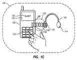
別の実施形態では、人間のインタラクションは、音声による有効化又は押しボタンによる有効化等により、同期処理の継続をユーザが承認することを要するステップを含む。例えば、図1Cは、追加的な人間のインタラクションが、ユーザがあるボタンを押すステップを含む場合の一例を示している。図1Cでは、ユーザはメディア配信機器100及びオーディオ出力機器102を、共有エンゲージメントゾーン120に位置させる。この時点で、すなわち同期化を継続する前に、メディア配信機器100はユーザに、本当にメディア配信機器100の同期化を希望しているかの確認を促すことができる。 In another embodiment, the human interaction includes steps that require the user to approve the continuation of the synchronization process, such as by voice activation or push button activation. For example, FIG. 1C shows an example where the additional human interaction includes the step of a user pressing a button. In FIG. 1C, the user places the
例えば、図1Cは、メディア配信機器100が表示画面128上に、ユーザに同期化の確認を促す確認のメッセージ132を表示することができる。確認するためには、ユーザはボタン124を押すだけで、メディア配信機器100に同期化を継続させることができる。このようにして、ユーザは、両方の装置が共有エンゲージメントゾーン120内にある間(近接検出モジュール108及び116内の下向き矢印で表現されている)に、ボタンを押すことにより、両方の装置の同期化機能を有効化することができる。 For example, in FIG. 1C, the
オーディオ出力機器102も追加的な人間のインタラクションを必要とすることもあり、場合によっては、メディア配信機器100及びオーディオ出力機器102の両方ともが、同期化を継続するためには追加的な人間のインタラクションを必要とすることもある。例えば、ユーザは、これらの装置が共有エンゲージメントゾーン120内にあって、かつ装置の1つ又は両方が、上述したような可聴インジケータの再生が終わるまでの間、個々の装置の同期化ボタン(不図示)を押している必要がある。 The
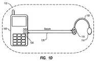
図1Dに示されているように、同期処理は最終的にワイヤレス通信チャンネル126を確立する。ワイヤレス通信チャンネル126を確立すると、メディア配信機器100及び/又はオーディオ出力機器102は、ワイヤレス通信チャンネル126を確立したことユーザに通知する。例えば、メディア配信機器100及び/又はオーディオ出力機器102は、ビープ音、ベル音、ブザー音、又は別の可聴アラート音を発する。別の実施例では、緑などの特定の色に変わる光源を装置が有している場合や、又は装置が短時間の振動を発生するのみの場合がある。 As shown in FIG. 1D, the synchronization process eventually establishes a
図1Dはまた、ワイヤレス通信チャンネル126を確立した後は、メディア配信機器100及びオーディオ出力機器102は、共有エンゲージメントゾーン120の範囲外であっても、ワイヤレス通信チャンネル126を通じてワイヤレスに通信することができることを、示している。例えば、メディア配信機器100はオーディオ出力機器102にオーディオメディアを送信し、オーディオ出力機器102がスピーカ組立体114を介してそのオーディオメディアを再生して、ユーザが楽しめるようにすることができる。 FIG. 1D also shows that once the
メディア配信機器100がデータを送信できることに加え、オーディオ出力機器102もデータを送信することができる。例えば、オーディオ出力機器102は、メディア配信機器100に特定の機能を実行させることを、ワイヤレス通信チャンネル126を通じて要求するよう構成された、オーディオコントロールパネル(不図示)を備えることができる。言い換えると、ユーザはオーディオ出力機器102上のボタンを押すことで、ワイヤレス通信チャンネルを用いてメディア配信機器100を制御することができる。例えば、ユーザはメディア配信機器100をポケット又はバックパックの中に収納していても、オーディオ出力機器102のボタンを押すことによって、メディア配信機器100における再生、停止、一時停止、又はメディアのトラック/チャンネルを変更することができる。 In addition to the
メディア配信機器100及びオーディオ出力機器102がワイヤレス通信レンジ122内に存在し続けている限り、メディア配信機器100及びオーディオ出力機器102は、ワイヤレス通信チャンネル126を介して通信を継続することができる。もちろん、ユーザがメディア配信機器100及び/又はオーディオ出力機器102をワイヤレス通信レンジ122の範囲外に移動すると、ワイヤレス通信チャンネルは切断される。 As long as the
切断されると、本発明の一実施形態では、メディア配信機器100及びオーディオ出力機器102は、ユーザが再びこれらの装置を共有エンゲージメントゾーン120に位置させた場合にのみ、ワイヤレス通信チャンネルを回復することができる。別の実施例では、例えば、メディア配信機器100及びオーディオ出力機器102は、以前のワイヤレス通信チャンネル126に関する識別データを記憶しており、それによって、メディア配信機器100及びオーディオ出力機器102がワイヤレス通信レンジ122内に戻ってくると(又はなんらかのユーザのインタラクションによって)、ワイヤレス通信チャンネル126を回復することが可能になる。 Once disconnected, in one embodiment of the present invention, the
自動的にワイヤレス通信チャンネルを回復する機能は、ユーザが選択可能なユーザオプションとして提供されてもよい。また反対に、ユーザがメディア配信機器100及び/又はオーディオ出力機器102の電源を切ると、以前のワイヤレス通信チャンネル126に関して記憶された識別データを削除する、というオプションをユーザは選択することもできる。したがって、この実施形態では、メディア配信機器100及びオーディオ出力機器102がワイヤレス通信チャンネル126を確立しても、ユーザが装置の1つ又は両方の電源を切るという選択をした場合は、ユーザはメディア配信機器100及びオーディオ出力機器102を再び同期化するためには、これらのワイヤレス装置を共有エンゲージメントゾーン120内に位置させなければならない。 The ability to automatically restore the wireless communication channel may be provided as a user selectable user option. Conversely, if the user turns off the
メディア配信機器100及びオーディオ出力機器102は、上述された機能を補助するさまざまな部品を備えることができる。例えば、図2は、メディア配信機器100及びオーディオ出力機器102の構成要素の例を示す概略図を例示している。上記のように、メディア配信機器100及びオーディオ出力機器102は、それぞれ近接検出モジュール108及び116を備えている。図2は、近接検出モジュール108及び116のそれぞれが、エミッタ(発生器)214及び226並びに検出器218及び230を、それぞれ有していることを示している。場合によっては、構成に応じて、磁気素子などの1つの構成要素がエミッタ及び検出器の両方として機能することがある。しかし通常は、エミッタ214及び226が近接信号110a及び110bをそれぞれ放出し、検出器218及び230が近接信号110a及び110bをそれぞれ検出する。 The
例えば、上記で簡単に説明したように、エミッタ214及び226は検出可能な磁界を生成する磁気素子であってもよい。磁気素子は、自然の磁気素材又は磁化された素材からなる永久磁石であってもよい。あるいは、磁気素子は、電流がかけられた時には磁気特性を示すが、電流が除去されると磁気特性を示さないような電磁石であってもよく、この場合、近接信号110a及び110bのオン及びオフを可能にしている。さらに、エミッタ214及び226は反対の極の磁界を放出するようにしてもよい。 For example, as briefly described above,
磁界を検出するために、検出器218及び230は、エミッタ214及び226によって発生された磁界を検出する磁界検出素子を備えることができる。一実施形態では、検出器は、磁界の存在又は強度を測定できる磁力計である。例えば、磁力計は、磁界の力を測定すること、あるいは磁界における変化を測定することができる。このようにして、検出器218及び230は、磁界の測定値、すなわち磁界の測定における特定の変化に基づいて、他方の装置上に位置しているエミッタ214及び226が所定のレンジ内にあるときを検出することができる。 In order to detect the magnetic field,
一実施形態では、検出器218及び230は一定の電流を有する電気回路を備えており、電気回路は特定の入力電圧及び既知の出力電圧を有している。このような電気回路の一例は、通常の分圧器である。電気回路はさらに、磁界にエネルギを保存し、かつ回路がインダクタンスを有するようにするインダクタを備えることができる。他の磁界(すなわち、別の装置のエミッタによる磁界等)がインダクタの周囲の磁界と相互作用すると、回路のインダクタンスが変化することにより、回路の出力電圧に変化が生じる。回路の出力電圧の変化を受けて、検出器は別のモジュールに信号を送信して、同期処理を有効化及び/又は実行することができる。 In one embodiment,
また別の例では、電気回路は一定の電圧を有することができる。ここでも、電気回路はインダクタを備えることができ、他の磁界(すなわち、別の装置のエミッタによる磁界等)がインダクタを囲む磁界と相互作用すると、回路のインダクタンスが変化することにより、回路の電流に変化が生じる。電流の変化を受けて、検出器は同期処理を有効化及び/又は実行することができる関連モジュールに、信号を送信することができる。 In another example, the electrical circuit can have a constant voltage. Again, the electrical circuit can include an inductor, and when another magnetic field (ie, the magnetic field from another device's emitter) interacts with the magnetic field surrounding the inductor, the circuit's inductance changes, causing the circuit's current to change. Changes. In response to a change in current, the detector can send a signal to an associated module that can enable and / or perform a synchronization process.
さらなる実施例では、検出器218及び230は、信号スイッチを閉じるために使用される磁気素子を備えており、該素子がアクティブ化されると、同期処理を有効化及び/又は実行する別のモジュールに信号が伝わる。例えば、信号スイッチは、通常オープン位置にバイアスされた素子を備え、別の磁石(すなわち、別の装置のエミッタの磁石)がスイッチ素子から所定の距離内に位置されると、磁界は信号スイッチを閉じる力をもたらし、これにより別の装置が共有エンゲージメントゾーン120内にあることを示すことができる。 In a further embodiment,
検出器218及び230が、それぞれエミッタ226及びエミッタ214によって生成された信号を検出すると、近接検出モジュール108及び116はその検出を、メディア配信機器100及びオーディオ出力機器102内の別のモジュールに通信することができる。図2は、近接検出モジュール108及び116が、それぞれ制御モジュール204及び234と通信している状態を示している。具体的には、近接検出モジュール108及び116が、近接信号110a及び110bをそれぞれ検出すると、制御モジュール204及び234は、同期処理を開始させる一連のコンピュータ実行可能命令を実行することができる。 When
該コンピュータ実行可能命令により、制御モジュール204及び234は、アラートモジュール202及び232に対して、ユーザへの可聴アラート、視覚アラート、又は振動アラートを発生するようそれぞれ指示し、メディア配信機器100及びオーディオ出力機器102が共有エンゲージメントゾーン120内にあること、及び/又は同期処理が進行中であることをユーザに通知できるようにする。同様に、コンピュータ実行可能命令によって、制御モジュール204及び234はそれぞれ、インターフェースモジュール208及び220に対して、上記で論じたように、表示画面128にメッセージ、グラフィック、又はアニメーションを表示するよう指示する。すると、インターフェースモジュール208及び220は、上述したような同期処理を継続するためのユーザ入力を要求(及び受信)することができる。 The computer-executable instructions cause
一実施例では、コンピュータ実行可能命令によって、制御モジュール204及び234が、それぞれ通信モジュール210及び222を有効化することができるよう、制御モジュール204及び234は、それぞれ通信モジュール210及び222と接続されている。例えば、制御モジュール204及び234は、通信モジュール210及び222と記憶モジュール206及び236との間のそれぞれの通信を許可及び/又は促進することができる。 In one embodiment, the
記憶モジュール206及び236にアクセスすることで、制御モジュール204及び234は、記憶されている同期データを読み出すことができ、かつ、同期暗号化キーすなわち同期暗号化コード等の同期データを保存するために、該データを記憶モジュール206及び236に送信することが可能になる。このように、制御モジュール204及び234は、記憶モジュール206及び236から通信モジュール210及び222への同期データの伝達を容易にし、通信モジュール210及び222は同期データの2つの装置間での共有を容易にすることができる。 By accessing the
例えば、図2が示すように、製造者は、通信モジュール210及び222をそれぞれワイヤレストランシーバ212及び224と接続することができる。したがって、通信モジュール210及び222は、ワイヤレス接続を用いて同期データを送受信することができる。別の実施形態では、通信モジュール210及び222は、送信機から分離して構成される受信機に接続することができる。さらに、通信モジュールの構成には、種々のプロトコル、周波数、レンジ、及び通信速度を用いることができる。通信モジュール210及び222はさらに、単一のワイヤレスチャンネルを介して通信すること又は複数のワイヤレスチャンネルを同時的に介して通信することができる。 For example, as FIG. 2 shows, a manufacturer can connect
通信モジュール210及び222が同期データを共有し、かつ同期データが記憶モジュール206及び236に記憶されると、例えば、メディア配信機器100とオーディオ出力機器102との間のワイヤレス通信チャンネル126を確立することにより、同期処理は完了する。このようにして、メディア配信機器100及びオーディオ出力機器102は、この2つの装置間において、上述したようにデータをワイヤレスで送信することができる。 Once the
したがって、図1A〜図1D及び図2並びにこれら図の説明は、効率的に同期化をさせて、ワイヤレス装置間にワイヤレス通信チャンネルを確立するような、数多くのさまざまな構成要素及びモジュールについて説明している。加えて、本発明の実施形態は、特定の成果を得るための方法の1又は複数の動作をフロー図によって説明することができる。例えば、図3は、第1の装置及び第2の装置間に、最小限の人間のインタラクションを用いて、ワイヤレス通信チャンネルを効率的に確立する方法を示している。図3の動作については、図1A〜図1D及び図2を参照して説明した構成要素に関連して、以下でさらに説明する。 Accordingly, FIGS. 1A-1D and 2 and the description of these figures describe many different components and modules that efficiently synchronize and establish a wireless communication channel between wireless devices. ing. In addition, embodiments of the present invention can illustrate one or more operations of a method for obtaining a particular outcome by way of a flow diagram. For example, FIG. 3 illustrates a method for efficiently establishing a wireless communication channel between a first device and a second device with minimal human interaction. The operation of FIG. 3 is further described below in connection with the components described with reference to FIGS. 1A-1D and 2.
例えば、図3は、メディア配信機器100の視点からみた方法が、オーディオ出力機器を検出するステップ302を含むことを示している。ステップ302は、オーディオ出力機器が、メディア配信機器の共有エンゲージメントゾーン内にあることを検出するステップである。例えば、図1Bは、オーディオ出力機器102が共有エンゲージメントゾーン120内にあるときは、メディア配信機器100の近接検出モジュール108が、近接信号110bを検出できることを示している。 For example, FIG. 3 shows that the method from the perspective of the
図3はさらに、該方法が、同期情報を送信するステップ304を含むことを示している。ステップ304は、オーディオ出力機器に同期情報を送信するステップを含む。例えば、図2は、制御モジュール204が通信モジュール210に対して、ワイヤレストランシーバ212を介してワイヤレス通信チャンネルを開始するよう指示して、メディア配信機器100が同期情報をオーディオ出力機器102に送信できるようにする場合の概略図を示している。 FIG. 3 further illustrates that the method includes a
また、図3は、該方法が、同期化応答を受信するステップ306を含むことを示している。ステップ306は、メディア配信機器及びオーディオ出力機器が、共有エンゲージメントゾーンよりも広いワイヤレス通信レンジを有する機密保護ワイヤレス通信チャンネルを確立することを可能にする、オーディオ出力機器からの同期化応答を、受信するステップを含む。例えば、図2は、通信モジュール210がワイヤレストランシーバ212を介して、オーディオ出力機器102からの同期化応答を受信する場合の概略図を示している。 FIG. 3 also shows that the method includes a
さらにまた、図3は、該方法が、オーディオ出力機器と通信するステップ308を含むことを示している。ステップ308は、共有エンゲージメントゾーン120の範囲外かつワイヤレス通信レンジの範囲内において、確立されたワイヤレス通信チャンネルを通じて、オーディオ出力機器と通信するステップを含む。例えば、図1Dは、装置がワイヤレス通信レンジ122内にはあるが共有エンゲージメントゾーン120の範囲外にある状態で、ワイヤレス通信チャンネル126を介してオーディオ出力機器102と通信するメディア配信機器100を示している。 Furthermore, FIG. 3 shows that the method includes a
同様に、オーディオ出力機器102の視点からみると、図3は、該方法が、メディア配信機器を検出するステップ310を含むことを示している。ステップ310は、メディア配信機器が、オーディオ出力機器の共有エンゲージメントゾーン内にあることを検出するステップを含む。例えば、図1Bは、メディア配信機器100が共有エンゲージメントゾーン120内にあるときは、オーディオ出力機器102の近接検出モジュール116が、近接信号110aを検出できることを示している。 Similarly, from the perspective of the
図3はさらに、オーディオ出力機器102の視点からみた該方法が、同期情報を送信するステップ312を含むことを示している。ステップ312は、メディア配信機器に同期情報を送信するステップを含む。例えば、図2は、制御モジュール234が通信モジュール222に対して、ワイヤレストランシーバ224を介してワイヤレス通信チャンネルを開始するよう指示し、オーディオ出力機器102が同期情報をメディア配信機器100に送信できるようにする場合の概略図を示している。 FIG. 3 further illustrates that the method from the perspective of the
また、図3は、オーディオ出力機器102の視点からみた該方法が、同期化応答を受信するステップ314を含むことを示している。ステップ314は、メディア配信機器及びオーディオ出力機器が、共有エンゲージメントゾーンよりも広いワイヤレス通信レンジを有する機密保護ワイヤレス通信チャンネルを確立することを可能にする、オーディオ出力機器からの同期化応答を、受信するステップを含む。例えば、図2は、通信モジュール222がワイヤレストランシーバ224を介して、メディア配信機器100からの同期化応答を受信する場合の概略図を示している。 FIG. 3 also shows that the method from the perspective of the
さらにまた、図3は、オーディオ出力機器102の視点からみた該方法が、メディア配信機器と通信するステップ316を含むことを示している。ステップ316は、共有エンゲージメントゾーン120の範囲外かつワイヤレス通信レンジの範囲内において、確立されたワイヤレス通信チャンネルを通じて、オーディオ出力機器と通信するステップを含む。例えば、図1Dは、装置がワイヤレス通信レンジ122内にはあるが共有エンゲージメントゾーン120の範囲外にある状態で、ワイヤレス通信チャンネル126を介してメディア配信機器100と通信するオーディオ出力機器102を示している。 Furthermore, FIG. 3 illustrates that the method from the perspective of the
このように、図1〜図3に対応する図式及び文章は、ワイヤレス装置間の機密保護ワイヤレス通信チャンネルを確立するために用いられる数多くの方法、装置、構成、及び部品を説明、又は何らかの方法で表現している。このような方法、装置、構成及び部品は、従来の装置及び方法と比べて、迅速かつ努力を要しないワイヤレス同期処理を提供することができる。さらに、本発明の実施形態は、不所望又は未知のワイヤレス装置とワイヤレス通信チャンネルを確立することのない、機密保護ワイヤレス通信チャンネルを提供している。したがって、本発明の実施形態は、2つのワイヤレス装置を同期化し、かつその間にワイヤレス通信チャンネルを確立するための、効果的、効率的、且つ機密保護手段を提供することができ、なおかつ、この同期化手段は、従来の機構よりもはるかに簡単かつ直観的なものである。 As such, the diagrams and texts corresponding to FIGS. 1-3 describe a number of methods, devices, configurations, and parts used to establish a secure wireless communication channel between wireless devices, or in some way. expressing. Such methods, apparatus, components and components can provide a wireless synchronization process that is quicker and effortless than conventional apparatuses and methods. Furthermore, embodiments of the present invention provide a secure wireless communication channel that does not establish a wireless communication channel with unwanted or unknown wireless devices. Accordingly, embodiments of the present invention can provide an effective, efficient, and secure means for synchronizing two wireless devices and establishing a wireless communication channel therebetween, yet this synchronization. The enabling means is much simpler and more intuitive than the conventional mechanism.
本発明の実施形態は、以下で詳細に論述されるさまざまなコンピュータハードウェアを備えた専用コンピュータ又は汎用コンピュータである。本発明の範囲内にある実施形態はさらに、コンピュータ実行可能命令すなわちそこに記憶されているデータ構造を備える又は有するコンピュータ可読媒体を含む。コンピュータ可読媒体は、汎用コンピュータ又は専用コンピュータによってアクセス可能な任意の利用可能なメディアであってよい。 Embodiments of the invention are special purpose computers or general purpose computers with various computer hardware discussed in detail below. Embodiments within the scope of the present invention further include computer-readable media comprising or having computer-executable instructions, ie data structures stored therein. Computer readable media can be any available media that can be accessed by a general purpose or special purpose computer.
例示であって限定するものではないが、コンピュータ可読媒体は、RAM、ROM、EEPROM、CD−ROM、などの光ディスク記憶装置、磁気ディスク記憶装置、などの磁気記憶装置、又は、コンピュータ実行可能命令すなわちデータ構造の形式で、所望のプログラムコード手段を備える又は記憶するために用いることができ、かつ汎用コンピュータ又は専用コンピュータによってアクセスが可能な、任意の別のメディアを含む。情報が、ネットワーク又は別の通信接続(有線、ワイヤレス、又は有線及びワイヤレスの組み合わせ、のいずれかの接続)によってコンピュータに転送又は提供される場合は、コンピュータは、その接続をコンピュータ可読媒体として厳密には識別する。したがって、任意の該接続は、正確にはコンピュータ可読媒体と称される。上記の組み合わせも、コンピュータ可読媒体の範囲に含まれるべきものである。 By way of illustration and not limitation, computer readable media includes optical storage such as RAM, ROM, EEPROM, CD-ROM, magnetic storage such as magnetic disk storage, or computer-executable instructions or It includes any other medium that can be used to provide or store the desired program code means in the form of a data structure and that can be accessed by a general purpose or special purpose computer. If information is transferred or provided to a computer by a network or another communication connection (either wired, wireless, or a combination of wired and wireless), the computer strictly refers to that connection as a computer-readable medium. Identifies. Thus, any such connection is accurately referred to as a computer-readable medium. Combinations of the above should also be included within the scope of computer-readable media.
コンピュータ実行可能命令は、例えば、汎用コンピュータ、専用コンピュータ、又は専用処理装置に、所定の機能又は一連の機能を実行させる、命令又はデータを備えている。本主題は、構造的な特性及び/又は方法論的動作に特有の表現で記載されているが、添付の特許請求の範囲で規定される本主題は、上述された特定の特性又は動作に限定されるものではない。むしろ、上述された特定の特性及び動作は、請求項の発明の実施の一形態例として開示されている。 Computer-executable instructions comprise, for example, instructions or data that cause a general purpose computer, special purpose computer, or special purpose processing device to perform a predetermined function or series of functions. Although the present subject matter has been described in terms of structural characteristics and / or methodological operations, the present subject matter as defined in the appended claims is limited to the specific features or acts described above. It is not something. Rather, the specific features and acts described above are disclosed as example forms of implementing the claimed invention.
本発明は、本発明の技術的思想すなわち本質的な特徴から逸脱しない範囲で、他の特定の形態で具体化することができる。記載された実施形態は全ての点において例示にすぎず、これらに限定するものではない。したがって、本発明の範囲は前述の記載によってではなく添付の特許請求の範囲によって規定される。該特許請求の範囲の同等物の意図及び範囲内に該当するあらゆる変更形態は、その範囲に含まれるものとする。 The present invention can be embodied in other specific forms without departing from the technical idea, that is, the essential features of the present invention. The described embodiments are merely exemplary in all respects and are not intended to be limiting. The scope of the invention is, therefore, defined by the appended claims rather than by the foregoing description. All changes that come within the spirit and scope of the equivalents of the claims are to be embraced within their scope.
Claims (23)
Translated fromJapaneseメディア配信機器に近接しかつ1又は複数のオーディオ出力機器のワイヤレス通信レンジ内にある共有エンゲージメントゾーンを認識するよう構成された近接検出モジュールであって、1又は複数のオーディオ出力機器が共有エンゲージメントゾーン内にあるかどうかを検出するよう構成された近接検出モジュールと、
1又は複数のオーディオ出力機器が共有エンゲージメントゾーン内にある場合、1又は複数のオーディオ出力機器とワイヤレス通信チャンネルを自動的に初期化しつ確立するよう構成された通信モジュールと
を備え、
メディア配信機器は、確立されたワイヤレス通信チャンネルを用いて、共有エンゲージメントゾーンの範囲外の1又は複数のオーディオ出力機器と通信するよう構成されている
ことを特徴とするメディア配信機器。One or more audio output devices in the wireless communication range are configured to communicate wirelessly with one or more audio output devices in the wireless communication range and automatically secure wireless communication channels based on proximity detection A media distribution device configured to establish,
A proximity detection module configured to recognize a shared engagement zone proximate to a media distribution device and within a wireless communication range of one or more audio output devices, wherein the one or more audio output devices are within the shared engagement zone A proximity detection module configured to detect whether or not
Comprising one or more audio output devices and a communication module configured to automatically initialize and establish a wireless communication channel when the one or more audio output devices are in a shared engagement zone;
The media delivery device is configured to communicate with one or more audio output devices outside the shared engagement zone using an established wireless communication channel.
該装置はさらに、1又は複数のオーディオ出力機器上の1又は複数の別のボタンに対応する、1又は複数の押し下げ可能なボタンを備え、
通信モジュールは、近接検出モジュールが共有エンゲージメントゾーン内に1又は複数のオーディオ出力機器を検出し、ユーザがメディア配信機器上の1又は複数の押し下げ可能ボタンを押し、かつユーザがオーディオ出力機器上の1又は複数の押し下げ可能ボタンを押したときに、ワイヤレス通信チャンネルを自動的に初期化しかつ確立するよう構成されている
ことを特徴とするメディア配信機器。The media distribution device according to claim 1, wherein
The apparatus further comprises one or more depressible buttons corresponding to one or more other buttons on the one or more audio output devices,
In the communication module, the proximity detection module detects one or more audio output devices in the shared engagement zone, the user presses one or more depressible buttons on the media distribution device, and the user presses one on the audio output device. Or a media distribution device configured to automatically initialize and establish a wireless communication channel when a plurality of depressible buttons are pressed.
オーディオ出力機器に近接しかつオーディオ出力機器のワイヤレス通信レンジ内にある共有エンゲージメントゾーンを検出するよう構成された近接検出モジュールであって、メディア配信機器が共有エンゲージメントゾーン内にあるかどうかを検出するよう構成された近接検出モジュールと、
メディア配信機器が共有エンゲージメントゾーン内にある場合、メディア配信機器とワイヤレス通信チャンネルを自動的に初期化しかつ確立するよう構成された通信モジュールと
を備え、
オーディオ出力機器は、該確立されたワイヤレス通信チャンネルを用いて、共有エンゲージメントゾーンの範囲外のメディア配信機器と通信するよう構成されていることを特徴とするオーディオ出力機器。Audio configured to communicate wirelessly with media distribution devices within the wireless communication range and automatically establish secure wireless communication channels with media distribution devices within the wireless communication range based on proximity detection An output device,
A proximity detection module configured to detect a shared engagement zone proximate to an audio output device and within the wireless communication range of the audio output device, wherein the media detection device detects whether the media distribution device is within the shared engagement zone A configured proximity detection module;
A media distribution device and a communication module configured to automatically initialize and establish a wireless communication channel when the media distribution device is in a shared engagement zone;
An audio output device configured to communicate with a media delivery device outside the shared engagement zone using the established wireless communication channel.
該装置はさらに、メディア配信機器上の1又は複数の別のボタンに対応する1又は複数の押し下げ可能なボタンを備え、
通信モジュールは、メディア配信機器が共有エンゲージメントゾーン内にあり、かつ、オーディオ出力機器上及びメディア配信機器上の1又は複数の押し下げ可能ボタンが同時に押されていることを検出すると、ワイヤレス通信チャンネルを自動的に初期化しかつ確立するよう構成される
ことを特徴とするメディア配信機器。The audio output device according to claim 9, wherein
The apparatus further comprises one or more depressible buttons corresponding to one or more other buttons on the media distribution device;
The communication module automatically activates the wireless communication channel when it detects that the media distribution device is in the shared engagement zone and one or more depressible buttons on the audio output device and the media distribution device are pressed at the same time. A media distribution device configured to be initialized and established automatically.
コンピュータ制御装置に近接しかつワイヤレス通信レンジ内にある共有エンゲージメントゾーンを検出するよう構成された近接検出モジュールであって、第2のコンピュータ制御装置が共有エンゲージメントゾーン内にあるかどうかを検出するよう構成された近接検出モジュールと、
第2のコンピュータ制御装置が共有エンゲージメントゾーン内にある場合、第2のコンピュータ制御装置とワイヤレス通信チャンネルを自動的に初期化し確立するよう構成された通信モジュールと
を備え、
コンピュータ制御装置は、確立されたワイヤレス通信チャンネルを用いて、共有エンゲージメントゾーンの範囲外の第2のコンピュータ制御装置と通信するよう構成されている
ことを特徴とするコンピュータ制御装置。Configured to communicate wirelessly with a second computer controller in the wireless communication range and automatically establish a secure wireless communication channel with the second computer controller in the wireless communication range based on proximity detection A computer control device configured as follows:
A proximity detection module configured to detect a shared engagement zone proximate to a computer controller and within a wireless communication range, wherein the proximity detection module is configured to detect whether a second computer controller is within the shared engagement zone Proximity detection module,
A communication module configured to automatically initialize and establish a wireless communication channel with the second computer controller when the second computer controller is in the shared engagement zone;
The computer controller is configured to communicate with a second computer controller outside the shared engagement zone using an established wireless communication channel.
オーディオ出力機器がメディア配信機器の共有エンゲージメントゾーン内にあることを検出するステップと、
同期情報をオーディオ出力機器に送信するステップと、
メディア配信機器及びオーディオ出力機器が、共有エンゲージメントゾーンよりも広いワイヤレス通信レンジを有する機密保護ワイヤレス通信チャンネルを確立することを可能にする同期応答を、オーディオ出力機器から受信するステップと、
確立されたワイヤレス通信チャンネルを介して、共有エンゲージメントゾーンの範囲外かつワイヤレス通信レンジの範囲内でオーディオ出力機器と通信するステップと
からなることを特徴とするコンピュータ化された方法。A computer that efficiently establishes a wireless communication channel between a media distribution device and an audio output device with minimal human involvement in a media distribution device configured to communicate wirelessly with an audio output device within a wireless communication range A method,
Detecting that the audio output device is within the shared engagement zone of the media distribution device;
Sending synchronization information to the audio output device;
Receiving a synchronization response from the audio output device that enables the media distribution device and the audio output device to establish a secure wireless communication channel having a wireless communication range wider than the shared engagement zone;
Communicating with the audio output device via an established wireless communication channel outside the shared engagement zone and within the wireless communication range.
該方法はさらに、メディア配信機器が、同期情報を送信する前に、ユーザに確認動作を催促するステップを含み、
該確認動作は、オーディオ出力機器が共有エンゲージメントゾーンに所定時間保持されていることを識別するステップを含む
ことを特徴とする方法。The method of claim 18, wherein:
The method further includes the step of the media distribution device prompting the user for a confirmation action before sending the synchronization information;
The method includes the step of identifying that the audio output device is held in the shared engagement zone for a predetermined time.
メディア配信機器がオーディオ出力機器の共有エンゲージメントゾーン内にあることを検出するステップと、
同期情報をメディア配信機器に送信するステップと、
オーディオ出力機器及びメディア配信機器が、共有エンゲージメントゾーンよりも広いワイヤレス通信レンジを有する機密保護ワイヤレス通信チャンネルを確立することを可能にする同期応答を、メディア配信機器から受信するステップと、
確立されたワイヤレス通信チャンネルを介して、共有エンゲージメントゾーンの範囲外かつワイヤレス通信レンジの範囲内でメディア配信機器と通信するステップと
からなることを特徴とするコンピュータ化された方法。An audio output device configured to communicate wirelessly with a media distribution device within a wireless communication range to efficiently establish a wireless communication channel between the audio output device and the media distribution device with minimal human involvement A computerized method,
Detecting that the media delivery device is within the shared engagement zone of the audio output device;
Sending synchronization information to the media delivery device;
Receiving a synchronization response from the media distribution device that enables the audio output device and the media distribution device to establish a secure wireless communication channel having a wireless communication range wider than the shared engagement zone;
Communicating with a media distribution device via an established wireless communication channel outside a shared engagement zone and within a wireless communication range.
オーディオ出力機器が、同期情報を送信する前に、ユーザに確認動作を催促するステップを含み、ここで確認動作は、メディア配信機器が共有エンゲージメントゾーンに特定時間保持されていたことを識別するステップを含むことを特徴とする方法。The method of claim 21 further comprises:
The audio output device includes prompting the user for a confirmation action before sending the synchronization information, wherein the confirmation action includes identifying that the media distribution device has been held in the shared engagement zone for a specific time. A method characterized by comprising.
Applications Claiming Priority (3)
| Application Number | Priority Date | Filing Date | Title |
|---|---|---|---|
| US17260009P | 2009-04-24 | 2009-04-24 | |
| US61/172,600 | 2009-04-24 | ||
| PCT/US2010/032210WO2010124190A2 (en) | 2009-04-24 | 2010-04-23 | Wireless synchronization mechanism |
Publications (3)
| Publication Number | Publication Date |
|---|---|
| JP2012525080Atrue JP2012525080A (en) | 2012-10-18 |
| JP2012525080A5 JP2012525080A5 (en) | 2013-06-13 |
| JP5588500B2 JP5588500B2 (en) | 2014-09-10 |
Family
ID=43011764
Family Applications (1)
| Application Number | Title | Priority Date | Filing Date |
|---|---|---|---|
| JP2012507420AActiveJP5588500B2 (en) | 2009-04-24 | 2010-04-23 | Wireless synchronization mechanism |
Country Status (6)
| Country | Link |
|---|---|
| US (1) | US8457557B2 (en) |
| EP (1) | EP2422559A4 (en) |
| JP (1) | JP5588500B2 (en) |
| CN (1) | CN102132614B (en) |
| CA (1) | CA2729983C (en) |
| WO (1) | WO2010124190A2 (en) |
Cited By (1)
| Publication number | Priority date | Publication date | Assignee | Title |
|---|---|---|---|---|
| KR20150106535A (en)* | 2014-03-12 | 2015-09-22 | 엘지전자 주식회사 | Mobile terminal and controlling method thereof |
Families Citing this family (81)
| Publication number | Priority date | Publication date | Assignee | Title |
|---|---|---|---|---|
| JP5511230B2 (en)* | 2009-06-12 | 2014-06-04 | キヤノン株式会社 | COMMUNICATION DEVICE, COMMUNICATION DEVICE CONTROL METHOD, AND PROGRAM |
| US9237395B2 (en) | 2009-11-25 | 2016-01-12 | Skullcandy, Inc. | Modular audio systems and related assemblies and methods |
| US9467780B2 (en) | 2010-01-06 | 2016-10-11 | Skullcandy, Inc. | DJ mixing headphones |
| US9532126B1 (en) | 2010-01-06 | 2016-12-27 | Skullcandy, Inc. | Audio earbud headphone for improved in-ear retention |
| US8515115B2 (en) | 2010-01-06 | 2013-08-20 | Skullcandy, Inc. | Audio earbud headphone with extended curvature |
| US20110181780A1 (en)* | 2010-01-25 | 2011-07-28 | Barton James M | Displaying Content on Detected Devices |
| US20110183654A1 (en)* | 2010-01-25 | 2011-07-28 | Brian Lanier | Concurrent Use of Multiple User Interface Devices |
| JP5823101B2 (en)* | 2010-06-24 | 2015-11-25 | 株式会社東芝 | Electronic apparatus, wireless device, and communication control method |
| KR101757870B1 (en)* | 2010-12-16 | 2017-07-26 | 엘지전자 주식회사 | Mobile terminal and control method therof |
| US20120220342A1 (en)* | 2011-02-18 | 2012-08-30 | Holliday Thomas R | Luminous cellphone display |
| US8917877B2 (en)* | 2011-10-12 | 2014-12-23 | Sony Corporation | Distance-based rendering of media files |
| US9422094B2 (en) | 2011-11-15 | 2016-08-23 | Skullcandy, Inc. | Packaging for headphones, packaged headphones, and related methods |
| US8942403B2 (en) | 2011-11-18 | 2015-01-27 | Skullcandy, Inc. | Wiring harness for clothing, electronic devices including such a wiring harness, and garments incorporating such a wiring harness and electronic device |
| US9143595B1 (en)* | 2011-11-29 | 2015-09-22 | Ryan Michael Dowd | Multi-listener headphone system with luminescent light emissions dependent upon selected channels |
| USD685759S1 (en) | 2011-12-19 | 2013-07-09 | Skullcandy, Inc. | Headphone |
| USD677241S1 (en) | 2011-12-19 | 2013-03-05 | Skullcandy, Inc. | Headphone |
| US9100745B2 (en) | 2012-01-09 | 2015-08-04 | Skullcandy, Inc. | Modular audio devices configured to emit differing sound profiles and related methods |
| US9439467B2 (en) | 2012-01-24 | 2016-09-13 | Skullcandy, Inc. | Accessory structures for connection between straps and related methods |
| US9131266B2 (en) | 2012-08-10 | 2015-09-08 | Qualcomm Incorporated | Ad-hoc media presentation based upon dynamic discovery of media output devices that are proximate to one or more users |
| USD689464S1 (en) | 2012-08-22 | 2013-09-10 | Skullcandy, Inc. | Headset |
| US8965028B2 (en) | 2012-08-23 | 2015-02-24 | Skullcandy, Inc. | Speakers, headphones, and kits related to vibrations in an audio system, and methods for forming same |
| US9717985B2 (en) | 2012-10-02 | 2017-08-01 | Razer (Asia-Pacific) Pte. Ltd. | Fragment-based mobile device application streaming utilizing crowd-sourcing |
| US9776078B2 (en) | 2012-10-02 | 2017-10-03 | Razer (Asia-Pacific) Pte. Ltd. | Application state backup and restoration across multiple devices |
| US9600552B2 (en) | 2012-10-02 | 2017-03-21 | Nextbit Systems Inc. | Proximity based application state synchronization |
| US9747000B2 (en) | 2012-10-02 | 2017-08-29 | Razer (Asia-Pacific) Pte. Ltd. | Launching applications on an electronic device |
| US9268655B2 (en) | 2012-10-02 | 2016-02-23 | Nextbit Systems Inc. | Interface for resolving synchronization conflicts of application states |
| US9106721B2 (en) | 2012-10-02 | 2015-08-11 | Nextbit Systems | Application state synchronization across multiple devices |
| US9654556B2 (en) | 2012-10-02 | 2017-05-16 | Razer (Asia-Pacific) Pte. Ltd. | Managing applications on an electronic device |
| US9112885B2 (en) | 2012-10-02 | 2015-08-18 | Nextbit Systems Inc. | Interactive multi-tasker |
| US8839377B2 (en)* | 2012-11-12 | 2014-09-16 | Htc Corporation | Information sharing method and system using the same |
| US9729211B2 (en)* | 2012-11-19 | 2017-08-08 | Bose Corporation | Proximity based wireless audio connection |
| US10929336B2 (en)* | 2012-11-19 | 2021-02-23 | Nokia Technologies Oy | Methods, apparatuses, and computer program products for synchronized conversation between co-located devices |
| USD701196S1 (en) | 2012-12-26 | 2014-03-18 | Skullcandy, Inc. | Headphone |
| USD701197S1 (en) | 2012-12-26 | 2014-03-18 | Skullcandy, Inc. | Headphone |
| US9025806B2 (en) | 2013-01-08 | 2015-05-05 | The Ketchum Group | Headphone assembly |
| JP6469593B2 (en) | 2013-02-21 | 2019-02-13 | ワイズ−セック・リミテッド | Proximity detection |
| EP2965182B1 (en) | 2013-03-05 | 2019-06-19 | Fasetto, Inc. | System and method for cubic graphical user interfaces |
| US9414145B2 (en) | 2013-03-15 | 2016-08-09 | Skullcandy, Inc. | Customizable headphone audio driver assembly, headphone including such an audio driver assembly, and related methods |
| US10123189B2 (en) | 2013-03-21 | 2018-11-06 | Razer (Asia-Pacific) Pte. Ltd. | Electronic device system restoration by tapping mechanism |
| US8954611B2 (en) | 2013-03-21 | 2015-02-10 | Nextbit Systems Inc. | Mechanism for sharing states of applications and devices across different user profiles |
| US20140316543A1 (en) | 2013-04-19 | 2014-10-23 | Qualcomm Incorporated | Configuring audio for a coordinated display session between a plurality of proximate client devices |
| TWI520620B (en)* | 2013-05-02 | 2016-02-01 | 晨星半導體股份有限公司 | Video playing method and television thereof |
| CN104184755A (en)* | 2013-05-21 | 2014-12-03 | 华为终端有限公司 | Webpage real-time communication method, system and terminal |
| CA2918687C (en) | 2013-07-18 | 2020-04-14 | Luke Malpass | System and method for multi-angle videos |
| USD733682S1 (en) | 2013-09-25 | 2015-07-07 | Skullcandy, Inc. | Portable speaker |
| US10095873B2 (en) | 2013-09-30 | 2018-10-09 | Fasetto, Inc. | Paperless application |
| US9894633B2 (en)* | 2013-12-06 | 2018-02-13 | Google Llc | Reminders based on device proximity using bluetooth LE |
| US9584402B2 (en) | 2014-01-27 | 2017-02-28 | Fasetto, Llc | Systems and methods for peer to peer communication |
| USD728533S1 (en) | 2014-03-31 | 2015-05-05 | Skullcandy, Inc. | Headphone |
| SE539249C2 (en)* | 2014-07-09 | 2017-05-30 | Cumbari Ab | Method and system for acquiring knowledge of proximity of an electronic device by another device for establishing communication |
| EP4322496A3 (en) | 2014-07-10 | 2024-05-01 | Fasetto, Inc. | Systems and methods for message editing |
| USD750042S1 (en) | 2014-07-14 | 2016-02-23 | Skullcandy, Inc. | Headphone microphone |
| US9668043B2 (en) | 2014-07-14 | 2017-05-30 | Skullcandy, Inc. | Elastomeric component for earbud headphones and headphones including such elastomeric components |
| USD758336S1 (en) | 2014-07-25 | 2016-06-07 | Skullcandy, Inc. | Portable speaker |
| USD757678S1 (en) | 2014-07-25 | 2016-05-31 | Skullcandy, Inc. | Portable speaker |
| USD758989S1 (en) | 2014-07-25 | 2016-06-14 | Skullcandy, Inc. | Portable speaker |
| US9486030B2 (en) | 2014-08-05 | 2016-11-08 | The Ketchum Group, Inc. | Audio pouch for helmet |
| US9993723B2 (en)* | 2014-09-25 | 2018-06-12 | Intel Corporation | Techniques for low power monitoring of sports game play |
| KR20220143963A (en) | 2014-10-06 | 2022-10-25 | 파세토, 인크. | Systems and methods for portable storage devices |
| US10437288B2 (en) | 2014-10-06 | 2019-10-08 | Fasetto, Inc. | Portable storage device with modular power and housing system |
| EP3041258B1 (en) | 2014-12-31 | 2018-02-28 | Skullcandy, Inc. | Methods of generating tactile user feedback utilizing headphone devices and related systems |
| EP3041261B1 (en) | 2014-12-31 | 2020-05-06 | Skullcandy, Inc. | Speaker assemblies for passive generation of vibrations and related headphone devices and methods |
| USD757680S1 (en) | 2015-01-05 | 2016-05-31 | Skullcandy, Inc. | Headphone |
| US9648412B2 (en) | 2015-02-06 | 2017-05-09 | Skullcandy, Inc. | Speakers and headphones related to vibrations in an audio system, and methods for operating same |
| EP3269124B1 (en) | 2015-03-11 | 2020-05-06 | Fasetto, Inc. | Method and device for web api communications |
| USD813844S1 (en) | 2015-07-20 | 2018-03-27 | Skullcandy, Inc. | Headphone |
| US10136214B2 (en) | 2015-08-11 | 2018-11-20 | Google Llc | Pairing of media streaming devices |
| USD824879S1 (en) | 2015-11-18 | 2018-08-07 | Skullcandy, Inc. | Portable speaker |
| USD824365S1 (en) | 2015-11-18 | 2018-07-31 | Skullcandy, Inc. | Portable speaker |
| US10929071B2 (en) | 2015-12-03 | 2021-02-23 | Fasetto, Inc. | Systems and methods for memory card emulation |
| US10824985B2 (en)* | 2016-03-09 | 2020-11-03 | Amazon Technologies, Inc. | Interactive mobile pick-up unit notification |
| EP3545661B1 (en) | 2016-11-23 | 2023-01-04 | Fasetto, Inc. | Systems and methods for streaming media |
| US11708051B2 (en) | 2017-02-03 | 2023-07-25 | Fasetto, Inc. | Systems and methods for data storage in keyed devices |
| WO2019079628A1 (en) | 2017-10-19 | 2019-04-25 | Fasetto, Inc. | Portable electronic device connection systems |
| AU2018374384A1 (en) | 2017-12-01 | 2020-07-23 | Fasetto, Inc. | Systems and methods for improved data encryption |
| TWI822762B (en) | 2018-04-17 | 2023-11-21 | 美商費瑟朵股份有限公司 | Device presentation with real-time feedback |
| DE102018127961A1 (en)* | 2018-11-08 | 2020-05-14 | Steute Technologies Gmbh & Co. Kg | Control unit and pairing procedure for one control unit |
| USD918177S1 (en)* | 2018-12-17 | 2021-05-04 | Sony Corporation | Earphone |
| USD908114S1 (en) | 2019-03-06 | 2021-01-19 | Skullcandy, Inc. | Earbud headset |
| USD907597S1 (en) | 2019-03-06 | 2021-01-12 | Skullcandy, Inc. | Earbud headset |
| USD899399S1 (en) | 2019-03-11 | 2020-10-20 | Skullcandy, Inc. | Earbud headset |
Citations (3)
| Publication number | Priority date | Publication date | Assignee | Title |
|---|---|---|---|---|
| JP2007507965A (en)* | 2003-10-03 | 2007-03-29 | コーニンクレッカ フィリップス エレクトロニクス エヌ ヴィ | Wireless system having configurable connections |
| JP2007243977A (en)* | 2007-04-16 | 2007-09-20 | Fujifilm Corp | Wireless LAN connection destination selection method |
| JP2009053967A (en)* | 2007-08-28 | 2009-03-12 | Canon Electronics Inc | Authentication device and authentication system using the same |
Family Cites Families (47)
| Publication number | Priority date | Publication date | Assignee | Title |
|---|---|---|---|---|
| US6424820B1 (en) | 1999-04-02 | 2002-07-23 | Interval Research Corporation | Inductively coupled wireless system and method |
| KR100362149B1 (en) | 1999-12-22 | 2002-11-23 | 엘지전자 주식회사 | Data synchronous method between mobile terminal and computer |
| US7577111B2 (en) | 2000-11-10 | 2009-08-18 | Toshiba Tec Kabushiki Kaisha | Method and system for wireless interfacing of electronic devices |
| US7155163B2 (en) | 2001-01-09 | 2006-12-26 | Agere Systems Inc. | Unified passcode pairing of piconet devices |
| US20020103008A1 (en) | 2001-01-29 | 2002-08-01 | Rahn Michael D. | Cordless communication between PDA and host computer using cradle |
| KR100368757B1 (en) | 2001-02-13 | 2003-01-24 | 삼성전자 주식회사 | Wireless headset apparatus for automatically establishing link and method thereof |
| US7039033B2 (en) | 2001-05-07 | 2006-05-02 | Ixi Mobile (Israel) Ltd. | System, device and computer readable medium for providing a managed wireless network using short-range radio signals |
| US8032084B2 (en) | 2001-07-18 | 2011-10-04 | Data Transfer & Communications Limited | Data security device |
| US7016334B2 (en) | 2001-08-17 | 2006-03-21 | Ixi Mobile ( Israel) Ltd. | Device, system, method and computer readable medium for fast recovery of IP address change |
| CN100359867C (en)* | 2001-10-16 | 2008-01-02 | 索尼株式会社 | Communication system and method, information processing apparatus and method, and information processing terminal and method |
| US20040203365A1 (en)* | 2002-06-13 | 2004-10-14 | Tetsuya Yamamoto | Radio communication with an intended device |
| US7110799B1 (en) | 2002-06-14 | 2006-09-19 | Symbol Technologies, Inc. | Mobile terminal for interoperating with a standard or push-button enabled headset |
| CN1672386A (en) | 2002-07-29 | 2005-09-21 | 皇家飞利浦电子股份有限公司 | Security system for devices in a network |
| US7142814B2 (en) | 2002-12-11 | 2006-11-28 | Shary Nassimi | Automatic Bluetooth inquiry mode headset |
| US20040203381A1 (en)* | 2002-12-31 | 2004-10-14 | Cahn Janet E. | Method and apparatus for data transfer |
| US7117001B2 (en) | 2003-11-04 | 2006-10-03 | Motorola, Inc. | Simultaneous voice and data communication over a wireless network |
| US7187768B1 (en) | 2004-03-04 | 2007-03-06 | Vxi Corporation | Apparatus for cord-free hands-free telephony |
| WO2005089387A2 (en) | 2004-03-16 | 2005-09-29 | Jaalaa, Inc. | High-reliability computer interface for wireless input devices |
| US7254367B2 (en) | 2004-06-23 | 2007-08-07 | Agere Systems Inc. | Method and apparatus for pairing and configuring wireless devices |
| US20060116107A1 (en) | 2004-11-24 | 2006-06-01 | Hulvey Robert W | System and method for pairing wireless headsets and headphones |
| US7778601B2 (en) | 2005-01-24 | 2010-08-17 | Broadcom Corporation | Pairing modular wireless earpiece/microphone (HEADSET) to a serviced base portion and subsequent access thereto |
| US20060189348A1 (en) | 2005-02-23 | 2006-08-24 | Memory Matrix, Inc. | Systems and methods for automatic synchronization of cellular telephones |
| US7463861B2 (en) | 2005-03-07 | 2008-12-09 | Broadcom Corporation | Automatic data encryption and access control based on bluetooth device proximity |
| US7925212B2 (en) | 2005-03-07 | 2011-04-12 | Broadcom Corporation | Automatic network and device configuration for handheld devices based on bluetooth device proximity |
| US20060205349A1 (en)* | 2005-03-08 | 2006-09-14 | Enq Semiconductor, Inc. | Apparatus and method for wireless audio network management |
| US7343177B2 (en) | 2005-05-03 | 2008-03-11 | Broadcom Corporation | Modular ear-piece/microphone (headset) operable to service voice activated commands |
| US7577459B2 (en) | 2005-05-11 | 2009-08-18 | Nokia Corporation | Establishing a communication link |
| US20070004387A1 (en) | 2005-06-30 | 2007-01-04 | Gadamsetty Uma M | Sharing of services between a mobile computer and a wireless device |
| JP4634878B2 (en)* | 2005-07-07 | 2011-02-16 | 株式会社東芝 | Wireless communication device |
| US7742758B2 (en) | 2005-08-19 | 2010-06-22 | Callpod, Inc. | Mobile conferencing and audio sharing technology |
| US7580254B2 (en) | 2005-10-19 | 2009-08-25 | David Anderson | Apparatus, system, and method for secure storage bay for an electronic handheld device |
| KR100774292B1 (en) | 2005-10-25 | 2007-11-08 | 삼성전자주식회사 | How to automatically connect Bluetooth on mobile terminal |
| US20070141989A1 (en) | 2005-12-21 | 2007-06-21 | Patent Navigation Inc. | Proximity facilitate device pairing |
| KR20070066025A (en) | 2005-12-21 | 2007-06-27 | 주식회사 팬택 | Connection device and method between Bluetooth devices |
| US7653352B2 (en) | 2005-12-22 | 2010-01-26 | Motorola, Inc. | Method and apparatus for self-assigning addresses |
| US8024811B2 (en)* | 2006-01-19 | 2011-09-20 | Research In Motion Limited | System and method for secure PIN exchange |
| KR100800733B1 (en)* | 2006-02-08 | 2008-02-01 | 삼성전자주식회사 | Bluetooth system and Bluetooth bonding process method |
| US20070197164A1 (en) | 2006-02-23 | 2007-08-23 | Arnold Sheynman | Method and device for automatic bluetooth pairing |
| KR100801876B1 (en) | 2006-07-28 | 2008-02-11 | 지씨티 세미컨덕터 인코포레이티드 | Voice data transmission method and system using wireless LAN and Bluetooth |
| KR100735413B1 (en) | 2006-08-08 | 2007-07-04 | 삼성전자주식회사 | Mobile communication terminal and voice input / output method for inputting / outputting voice while playing music data using Bluetooth |
| US7813715B2 (en) | 2006-08-30 | 2010-10-12 | Apple Inc. | Automated pairing of wireless accessories with host devices |
| KR100817594B1 (en) | 2006-09-05 | 2008-03-27 | 삼성전자주식회사 | Method and device for automatically connecting between Bluetooth devices |
| KR101307456B1 (en) | 2006-09-22 | 2013-09-11 | 삼성전자주식회사 | Method and apparatus for providing bluetooth auto pairing in Mobile terminal |
| KR100782083B1 (en) | 2006-10-11 | 2007-12-04 | 삼성전자주식회사 | Sound reproduction system of mobile terminal and its operation method |
| US8103247B2 (en) | 2006-10-31 | 2012-01-24 | Microsoft Corporation | Automated secure pairing for wireless devices |
| KR101392571B1 (en) | 2006-11-16 | 2014-05-08 | 엘지전자 주식회사 | Near Field Communication Interface Control |
| KR100911937B1 (en) | 2007-05-04 | 2009-08-13 | 주식회사 케이티테크 | Searching method for a device capable of short-range wireless communication, a recording medium recording a device and a program for implementing the same |
- 2010
- 2010-04-23CACA2729983Apatent/CA2729983C/enactiveActive
- 2010-04-23JPJP2012507420Apatent/JP5588500B2/enactiveActive
- 2010-04-23CNCN201080002402.5Apatent/CN102132614B/enactiveActive
- 2010-04-23WOPCT/US2010/032210patent/WO2010124190A2/enactiveApplication Filing
- 2010-04-23EPEP10767830.2Apatent/EP2422559A4/ennot_activeWithdrawn
- 2010-04-23USUS12/811,081patent/US8457557B2/enactiveActive
Patent Citations (3)
| Publication number | Priority date | Publication date | Assignee | Title |
|---|---|---|---|---|
| JP2007507965A (en)* | 2003-10-03 | 2007-03-29 | コーニンクレッカ フィリップス エレクトロニクス エヌ ヴィ | Wireless system having configurable connections |
| JP2007243977A (en)* | 2007-04-16 | 2007-09-20 | Fujifilm Corp | Wireless LAN connection destination selection method |
| JP2009053967A (en)* | 2007-08-28 | 2009-03-12 | Canon Electronics Inc | Authentication device and authentication system using the same |
Cited By (2)
| Publication number | Priority date | Publication date | Assignee | Title |
|---|---|---|---|---|
| KR20150106535A (en)* | 2014-03-12 | 2015-09-22 | 엘지전자 주식회사 | Mobile terminal and controlling method thereof |
| KR102210631B1 (en)* | 2014-03-12 | 2021-02-02 | 엘지전자 주식회사 | Mobile terminal and controlling method thereof |
Also Published As
| Publication number | Publication date |
|---|---|
| WO2010124190A2 (en) | 2010-10-28 |
| WO2010124190A3 (en) | 2011-01-20 |
| CN102132614A (en) | 2011-07-20 |
| CA2729983C (en) | 2016-07-26 |
| EP2422559A2 (en) | 2012-02-29 |
| CA2729983A1 (en) | 2010-10-28 |
| EP2422559A4 (en) | 2015-07-22 |
| JP5588500B2 (en) | 2014-09-10 |
| CN102132614B (en) | 2016-01-20 |
| US8457557B2 (en) | 2013-06-04 |
| US20120128172A1 (en) | 2012-05-24 |
Similar Documents
| Publication | Publication Date | Title |
|---|---|---|
| JP5588500B2 (en) | Wireless synchronization mechanism | |
| KR100710740B1 (en) | Method and device for identifying and pairing bluetooth devices | |
| US9762317B2 (en) | Playing synchronized mutichannel media on a combination of devices | |
| JP6015265B2 (en) | Proximity communication system | |
| US20080003945A1 (en) | Interoperation of Terminals | |
| US12096167B2 (en) | Bidirectional configuration of sensor nodes with mobile phone with no extension | |
| US10606551B2 (en) | Content streaming apparatus and method | |
| US9001813B2 (en) | Radio system with configurable links | |
| CN103023866A (en) | Easy sharing of wireless audio signals | |
| CN108174459B (en) | Wireless audio device pairing method and wireless audio device | |
| CN111770416B (en) | Speaker control method, device and electronic device | |
| US20240276150A1 (en) | Stereo networking method, electronic device, audio device, and storage medium | |
| CN115604801A (en) | Presentation method, device, target device, electronic device, connection system and medium | |
| KR20130031086A (en) | Content sharing in home network | |
| KR102077563B1 (en) | home appliance, and method for operating the same | |
| US20170366973A1 (en) | Wireless security system for wireless audio device | |
| JP6172365B2 (en) | Proximity communication system and proximity communication device | |
| KR200317020Y1 (en) | Handset Equipped with Portable Multi-Function Remote Control | |
| TWI628652B (en) | Intelligent earphone device personalization system for users to safely go out and use method thereof | |
| JP4715061B2 (en) | Transmission / reception device, reception device, transmission method, and reception method | |
| CN120693878A (en) | Display device and operating method thereof | |
| KR20040082054A (en) | Handset Equipped with Portable Multi-Function Remote Control |
Legal Events
| Date | Code | Title | Description |
|---|---|---|---|
| A521 | Request for written amendment filed | Free format text:JAPANESE INTERMEDIATE CODE: A523 Effective date:20130422 | |
| A621 | Written request for application examination | Free format text:JAPANESE INTERMEDIATE CODE: A621 Effective date:20130422 | |
| A977 | Report on retrieval | Free format text:JAPANESE INTERMEDIATE CODE: A971007 Effective date:20140205 | |
| A131 | Notification of reasons for refusal | Free format text:JAPANESE INTERMEDIATE CODE: A131 Effective date:20140213 | |
| A601 | Written request for extension of time | Free format text:JAPANESE INTERMEDIATE CODE: A601 Effective date:20140513 | |
| A602 | Written permission of extension of time | Free format text:JAPANESE INTERMEDIATE CODE: A602 Effective date:20140520 | |
| A521 | Request for written amendment filed | Free format text:JAPANESE INTERMEDIATE CODE: A523 Effective date:20140606 | |
| TRDD | Decision of grant or rejection written | ||
| A01 | Written decision to grant a patent or to grant a registration (utility model) | Free format text:JAPANESE INTERMEDIATE CODE: A01 Effective date:20140627 | |
| A61 | First payment of annual fees (during grant procedure) | Free format text:JAPANESE INTERMEDIATE CODE: A61 Effective date:20140725 | |
| R150 | Certificate of patent or registration of utility model | Ref document number:5588500 Country of ref document:JP Free format text:JAPANESE INTERMEDIATE CODE: R150 | |
| R250 | Receipt of annual fees | Free format text:JAPANESE INTERMEDIATE CODE: R250 | |
| R250 | Receipt of annual fees | Free format text:JAPANESE INTERMEDIATE CODE: R250 | |
| R250 | Receipt of annual fees | Free format text:JAPANESE INTERMEDIATE CODE: R250 | |
| R250 | Receipt of annual fees | Free format text:JAPANESE INTERMEDIATE CODE: R250 | |
| R250 | Receipt of annual fees | Free format text:JAPANESE INTERMEDIATE CODE: R250 | |
| R250 | Receipt of annual fees | Free format text:JAPANESE INTERMEDIATE CODE: R250 | |
| R250 | Receipt of annual fees | Free format text:JAPANESE INTERMEDIATE CODE: R250 | |
| R250 | Receipt of annual fees | Free format text:JAPANESE INTERMEDIATE CODE: R250 | |
| R250 | Receipt of annual fees | Free format text:JAPANESE INTERMEDIATE CODE: R250 |