JP2012524261A - Deep tissue temperature probe structure - Google Patents
Deep tissue temperature probe structureDownload PDFInfo
- Publication number
- JP2012524261A JP2012524261AJP2012505882AJP2012505882AJP2012524261AJP 2012524261 AJP2012524261 AJP 2012524261AJP 2012505882 AJP2012505882 AJP 2012505882AJP 2012505882 AJP2012505882 AJP 2012505882AJP 2012524261 AJP2012524261 AJP 2012524261A
- Authority
- JP
- Japan
- Prior art keywords
- support assembly
- regions
- heater
- support
- base
- Prior art date
- Legal status (The legal status is an assumption and is not a legal conclusion. Google has not performed a legal analysis and makes no representation as to the accuracy of the status listed.)
- Pending
Links
- 239000000523sampleSubstances0.000titleclaimsabstractdescription62
- 230000001681protective effectEffects0.000claimsabstractdescription4
- 230000002093peripheral effectEffects0.000claimsdescription15
- 239000011810insulating materialSubstances0.000claimsdescription5
- 230000004907fluxEffects0.000abstractdescription10
- RYGMFSIKBFXOCR-UHFFFAOYSA-NCopperChemical compound[Cu]RYGMFSIKBFXOCR-UHFFFAOYSA-N0.000description13
- 229910052802copperInorganic materials0.000description13
- 239000010949copperSubstances0.000description13
- 238000005259measurementMethods0.000description12
- 238000009413insulationMethods0.000description8
- 239000004820Pressure-sensitive adhesiveSubstances0.000description7
- 238000009529body temperature measurementMethods0.000description7
- 239000002131composite materialSubstances0.000description5
- 229910052782aluminiumInorganic materials0.000description4
- XAGFODPZIPBFFR-UHFFFAOYSA-NaluminiumChemical compound[Al]XAGFODPZIPBFFR-UHFFFAOYSA-N0.000description4
- 229910001179chromelInorganic materials0.000description4
- 239000004020conductorSubstances0.000description4
- 230000036757core body temperatureEffects0.000description4
- 239000002985plastic filmSubstances0.000description4
- 229920006255plastic filmPolymers0.000description4
- 239000000463materialSubstances0.000description3
- PXHVJJICTQNCMI-UHFFFAOYSA-NNickelChemical compound[Ni]PXHVJJICTQNCMI-UHFFFAOYSA-N0.000description2
- 239000004642PolyimideSubstances0.000description2
- 230000015572biosynthetic processEffects0.000description2
- 230000036760body temperatureEffects0.000description2
- 238000005219brazingMethods0.000description2
- 238000005530etchingMethods0.000description2
- 208000015181infectious diseaseDiseases0.000description2
- 229910052751metalInorganic materials0.000description2
- 239000002184metalSubstances0.000description2
- 238000012544monitoring processMethods0.000description2
- 229920001721polyimidePolymers0.000description2
- 238000000926separation methodMethods0.000description2
- 238000005476solderingMethods0.000description2
- 238000003466weldingMethods0.000description2
- 208000003322CoinfectionDiseases0.000description1
- 229910000599Cr alloyInorganic materials0.000description1
- 241001465754MetazoaSpecies0.000description1
- 229910000990Ni alloyInorganic materials0.000description1
- 239000000853adhesiveSubstances0.000description1
- 230000001070adhesive effectEffects0.000description1
- 230000009286beneficial effectEffects0.000description1
- 230000006835compressionEffects0.000description1
- 238000007906compressionMethods0.000description1
- MPTQRFCYZCXJFQ-UHFFFAOYSA-Lcopper(II) chloride dihydrateChemical compoundO.O.[Cl-].[Cl-].[Cu+2]MPTQRFCYZCXJFQ-UHFFFAOYSA-L0.000description1
- 238000012864cross contaminationMethods0.000description1
- 238000013461designMethods0.000description1
- 238000010586diagramMethods0.000description1
- PCHJSUWPFVWCPO-UHFFFAOYSA-NgoldChemical compound[Au]PCHJSUWPFVWCPO-UHFFFAOYSA-N0.000description1
- 229910052737goldInorganic materials0.000description1
- 239000010931goldSubstances0.000description1
- 238000010438heat treatmentMethods0.000description1
- 239000012774insulation materialSubstances0.000description1
- 238000004519manufacturing processMethods0.000description1
- 150000002739metalsChemical class0.000description1
- 238000000034methodMethods0.000description1
- 238000012986modificationMethods0.000description1
- 230000004048modificationEffects0.000description1
- 229920003223poly(pyromellitimide-1,4-diphenyl ether)Polymers0.000description1
- 229920000728polyesterPolymers0.000description1
- 230000005855radiationEffects0.000description1
- 238000012827research and developmentMethods0.000description1
- 230000008326skin blood flowEffects0.000description1
- 238000001356surgical procedureMethods0.000description1
- 238000012546transferMethods0.000description1
- 230000001052transient effectEffects0.000description1
- 238000007740vapor depositionMethods0.000description1
Images


Classifications
- G—PHYSICS
- G01—MEASURING; TESTING
- G01K—MEASURING TEMPERATURE; MEASURING QUANTITY OF HEAT; THERMALLY-SENSITIVE ELEMENTS NOT OTHERWISE PROVIDED FOR
- G01K1/00—Details of thermometers not specially adapted for particular types of thermometer
- G01K1/16—Special arrangements for conducting heat from the object to the sensitive element
- G01K1/165—Special arrangements for conducting heat from the object to the sensitive element for application in zero heat flux sensors
- A—HUMAN NECESSITIES
- A61—MEDICAL OR VETERINARY SCIENCE; HYGIENE
- A61B—DIAGNOSIS; SURGERY; IDENTIFICATION
- A61B5/00—Measuring for diagnostic purposes; Identification of persons
- A61B5/01—Measuring temperature of body parts ; Diagnostic temperature sensing, e.g. for malignant or inflamed tissue
- A—HUMAN NECESSITIES
- A61—MEDICAL OR VETERINARY SCIENCE; HYGIENE
- A61B—DIAGNOSIS; SURGERY; IDENTIFICATION
- A61B5/00—Measuring for diagnostic purposes; Identification of persons
- A61B5/68—Arrangements of detecting, measuring or recording means, e.g. sensors, in relation to patient
- A61B5/6801—Arrangements of detecting, measuring or recording means, e.g. sensors, in relation to patient specially adapted to be attached to or worn on the body surface
- A61B5/683—Means for maintaining contact with the body
- A61B5/6832—Means for maintaining contact with the body using adhesives
- A61B5/6833—Adhesive patches
- A—HUMAN NECESSITIES
- A61—MEDICAL OR VETERINARY SCIENCE; HYGIENE
- A61B—DIAGNOSIS; SURGERY; IDENTIFICATION
- A61B5/00—Measuring for diagnostic purposes; Identification of persons
- A61B5/68—Arrangements of detecting, measuring or recording means, e.g. sensors, in relation to patient
- A61B5/6801—Arrangements of detecting, measuring or recording means, e.g. sensors, in relation to patient specially adapted to be attached to or worn on the body surface
- A61B5/6843—Monitoring or controlling sensor contact pressure
- G—PHYSICS
- G01—MEASURING; TESTING
- G01K—MEASURING TEMPERATURE; MEASURING QUANTITY OF HEAT; THERMALLY-SENSITIVE ELEMENTS NOT OTHERWISE PROVIDED FOR
- G01K1/00—Details of thermometers not specially adapted for particular types of thermometer
- G01K1/16—Special arrangements for conducting heat from the object to the sensitive element
- G—PHYSICS
- G01—MEASURING; TESTING
- G01K—MEASURING TEMPERATURE; MEASURING QUANTITY OF HEAT; THERMALLY-SENSITIVE ELEMENTS NOT OTHERWISE PROVIDED FOR
- G01K13/00—Thermometers specially adapted for specific purposes
- G01K13/20—Clinical contact thermometers for use with humans or animals
- A—HUMAN NECESSITIES
- A61—MEDICAL OR VETERINARY SCIENCE; HYGIENE
- A61B—DIAGNOSIS; SURGERY; IDENTIFICATION
- A61B2562/00—Details of sensors; Constructional details of sensor housings or probes; Accessories for sensors
- A61B2562/02—Details of sensors specially adapted for in-vivo measurements
- A61B2562/0271—Thermal or temperature sensors
- A61B2562/0276—Thermal or temperature sensors comprising a thermosensitive compound
- A—HUMAN NECESSITIES
- A61—MEDICAL OR VETERINARY SCIENCE; HYGIENE
- A61B—DIAGNOSIS; SURGERY; IDENTIFICATION
- A61B2562/00—Details of sensors; Constructional details of sensor housings or probes; Accessories for sensors
- A61B2562/16—Details of sensor housings or probes; Details of structural supports for sensors
- A61B2562/164—Details of sensor housings or probes; Details of structural supports for sensors the sensor is mounted in or on a conformable substrate or carrier
Landscapes
- Life Sciences & Earth Sciences (AREA)
- Health & Medical Sciences (AREA)
- Physics & Mathematics (AREA)
- Heart & Thoracic Surgery (AREA)
- Molecular Biology (AREA)
- Pathology (AREA)
- Engineering & Computer Science (AREA)
- Biomedical Technology (AREA)
- Veterinary Medicine (AREA)
- Medical Informatics (AREA)
- Biophysics (AREA)
- Surgery (AREA)
- Animal Behavior & Ethology (AREA)
- General Health & Medical Sciences (AREA)
- Public Health (AREA)
- General Physics & Mathematics (AREA)
- Measuring And Recording Apparatus For Diagnosis (AREA)
Abstract
Translated fromJapaneseDescription
Translated fromJapanese 優先権
本願は2009年4月15日出願による米国仮特許願61/212,749の優先権を主張する。Priority This application claims priority to US provisional patent application 61 / 212,749 filed April 15, 2009.
背景
本発明は、体温測定のために対象者の皮膚上に設置する装置、すなわち温度プローブに関する。特に、本発明は、深部組織用温度(DTT)プローブに関する。深部組織の温度測定は、人体の中核体温を非侵襲的に決定するものである。プローブは身深部組織を代表する深部組織領域の体表に配置される。プローブはその領域の温度を中核体温として読み取る。BACKGROUND The present invention relates to an apparatus placed on a subject's skin for measuring body temperature, that is, a temperature probe. In particular, the present invention relates to deep tissue temperature (DTT) probes. Deep tissue temperature measurement non-invasively determines the core body temperature of the human body. The probe is arranged on the body surface of a deep tissue region representing the deep tissue. The probe reads the temperature in that area as the core body temperature.
非侵襲的に深部組織の温度を測定するシステムは、フォックスとソルマンによって1971年に解説されている(非特許文献1、フォックス RH、ソルマン AJ「無傷の皮膚表面から人の深部組織の温度を監視するための新技術」生理学学会誌1971年1月:212(2):8頁〜10頁)。図1で図示されているシステムは、人体の皮膚の一部において、熱の通過を阻止または妨害する特殊なプローブ10を使用した間接的手段によって、中核体温を評価する。プローブ10の構成要素は、筐体11内に収納されている。プローブ10は熱抵抗22の両側に取り付けられた2つのサーミスタ20を含む。熱抵抗22はサーミスタ20を支持する絶縁材料層でなる。プローブ10はさらに、プローブ10の上面に配置されているヒータ24(加熱手段24)を含む。ヒータ24は、サーミスタ20及び熱抵抗22の上方に位置する。利用の際にはプローブ10は深部組織の温度が測定される皮膚領域に配置される。人体上に置かれたプローブの底面26は皮膚と接触し、サーミスタ20は、熱抵抗22の両側の温度差または熱抵抗22を越えたエラー信号を測定する。このエラー信号は、ヒータ制御手段30を運用するために使用される。ヒータ制御手段30は、熱抵抗22の両側の温度を均等化させるのに十分な熱量だけをヒータ24に提供させることでエラー信号を最小化するように機能する。サーミスタ20で検知された両方の温度が等しくなるとプローブには熱が流れなくなり、増幅器36と温度計38とで成る温度計回路を利用して下方のサーミスタ20によって測定される温度は、DTTと等しくなる。プローブ10は、実質的に、熱抵抗22を通過する熱流を遮断する断熱要素として機能する。同様に機能するDTTプローブは、「熱流束がゼロである、ゼロ熱流束」(ZHF)プローブと呼称される。ヒータ24は、プローブを通過する温度測定経路に沿った熱損失を防護するように機能するため、しばしば「防護ヒータ」と呼称される。 A system for noninvasively measuring deep tissue temperature was described in 1971 by Fox and Solman (Non-Patent
トガワは、フォックスとソルマンの設計によるプローブを、皮膚を通過する皮膚血流の強力な多次元の熱移動を利用したDTTプローブ構造体により改良した(非特許文献2,トガワ T「非侵襲性の深部組織の温度測定」、ロルフP(編集)、非侵襲生理学的な測定、第1巻,1979年,アカデミックプレス社,ロンドン、261頁〜277頁)。図2で図示されているプローブは身体に対して垂直方向に流れる熱流を遮断するZHFセンサ要素40を円盤状の構造体の厚手のアルミ製の筐体42に内包している。この円盤状の構造体は、プローブの中心部から周辺部への放射状の熱流も減少あるいは排除する。 Togawa improved the probe designed by Fox and Solman with a DTT probe structure that utilizes the powerful multidimensional heat transfer of skin blood flow through the skin (Non-Patent
熱抵抗を通過する熱流を遮断するヒータの運用を制御するためにフォックスとソルマン、及びトガワは身体(及びプローブが配置される皮膚)に対して垂直な熱流束を利用する。その結果、プローブの構成要素を積み重ねる構造が提供され、実質的にプローブを垂直形態物としている。トガワのプローブ設計によって加えられる熱質量は、フォックスとソルマンのプローブの安定性もまた改善する。熱流束測定のための基本的技術によれば、プローブの大きな熱抵抗は測定をさらに正確にすることが示唆されているが、過渡応答率は遅くなる。最終目標は、測定子を横断する厚み方向の熱流束をゼロにすることであるため、熱抵抗値が大きければ大きいほど良いことになる。しかしながら、熱抵抗の追加は、重量を増加させ、全体の寸法(サイズ)を大きくする。 Fox, Solman, and Togawa use heat flux perpendicular to the body (and the skin on which the probe is placed) to control the operation of the heater that blocks the heat flow through the thermal resistance. As a result, a structure for stacking the components of the probe is provided, substantially making the probe a vertical configuration. The thermal mass applied by the Togawa probe design also improves the stability of the Fox and Solman probes. Although basic techniques for heat flux measurement suggest that the large thermal resistance of the probe makes the measurement more accurate, the transient response rate is slower. Since the final goal is to zero the heat flux in the thickness direction across the probe, the higher the thermal resistance, the better. However, the addition of thermal resistance increases weight and increases overall dimensions (size).
周術期の身体の中核温度を正常体温の範囲内に維持することは、手術部位の感染の発生率を低減させることが証明されている。よって、患者の体の中核温度を、手術前、手術中及び手術後に監視することは有意義である。もちろん患者の快適性及び安全性に鑑みて非侵襲測定が望ましい。皮膚上に配置するプローブを利用した深部組織の温度測定は、体の中核温度を監視するための正確で非侵襲的な手段である。しかし、フォックスとソルマン及びトガワのプローブの大きさ及び重量は、プローブの廃棄性を促進しない。従って、それらプローブは毎使用後に滅菌し、再使用に備えなければならない。その結果、深部組織の温度の測定のためのそれらプローブの使用は、DTT測定に関連する費用を増加させ、患者間の二次感染のリスクを高める可能性がある。従って性能を犠牲にすることなく廃棄性を高めるためにDTTプローブの大きさと重量を減少させることは有益である。 Maintaining the core temperature of the perioperative body within normal body temperature has been shown to reduce the incidence of infection at the surgical site. It is therefore meaningful to monitor the core temperature of a patient's body before, during and after surgery. Of course, non-invasive measurements are desirable in view of patient comfort and safety. Deep tissue temperature measurement using a probe placed on the skin is an accurate and non-invasive means for monitoring core body temperature. However, the size and weight of Fox and Solman and Togawa probes does not promote probe disposal. Therefore, the probes must be sterilized after each use and prepared for reuse. As a result, the use of these probes for measuring deep tissue temperature may increase the costs associated with DTT measurements and increase the risk of secondary infection between patients. Therefore, it is beneficial to reduce the size and weight of the DTT probe in order to increase discardability without sacrificing performance.
概要
使い捨ての、ゼロ熱流束型の深部組織用温度プローブは、プローブの要素を支持する柔軟な基部を含んで構成された組立品を利用して構成される。支持組立体の一つの実施態様は、構造体に取り付けられた複数領域ヒータ、熱センサ、及び熱抵抗を備えた層状要素を備えている。ヒータは、この層状要素を貫通して形成された開口部によって規定された複数の領域(マルチゾーン)を有しており、これらの領域の間では、プローブの柔軟性が付与されている。別の支持組立品は、被覆防護ヒータと、中央の熱センサと、中央の熱センサから少なくとも半径方向にずらされている熱センサと、を支持する複数の層状要素を備えている。Overview A disposable, zero heat flux, deep tissue temperature probe is constructed utilizing an assembly that includes a flexible base that supports the elements of the probe. One embodiment of the support assembly includes a multi-layer heater attached to the structure, a thermal sensor, and a layered element with thermal resistance. The heater has a plurality of regions (multi-zones) defined by openings formed through the layered elements, and the flexibility of the probe is given between these regions. Another support assembly includes a plurality of layered elements that support a sheathed protective heater, a central thermal sensor, and a thermal sensor that is at least radially offset from the central thermal sensor.
図面の簡単な説明
好適実施形態の詳細な説明
ゼロ熱流束型の深部組織用温度プローブ(DTTプローブ)構造体は使い捨てタイプであることが望ましい。よって構造体は、製造と組立とが簡単で低コストであり、軽量小型であって、しかも安価な材料と部品を使うものであることが望ましい。DETAILED DESCRIPTION OF PREFERRED EMBODIMENTS The zero heat flux type deep tissue temperature probe (DTT probe) structure is preferably a disposable type. Therefore, it is desirable that the structure is easy to manufacture and assemble, is low-cost, is light and small, and uses inexpensive materials and parts.
使い捨てタイプのDTT構造体は、人間または動物の身体の様々な箇所にてゼロ熱流束測定を可能にする、薄型で、軽量で、柔軟な組立体として組み立てられることが特に望ましい。 Disposable DTT structures are particularly desirable to be assembled as a thin, lightweight, flexible assembly that allows zero heat flux measurements at various points in the human or animal body.
ゼロ熱流束の深部組織用温度(DTT)プローブ構造体のための熱測定用支持組立体は、柔軟な基部を含む。この基部には少なくとも2つの熱センサが互いに離れた状態で取り付けられており、それらセンサは、一層又はそれ以上の断熱材の層で分離されている。好適には、これらセンサは、図1と図2で示すように垂直方向で離れて構築されている。それらはさらに垂直方向の熱流束の測定中心から水平または半径方向(放射状)に離れている。基部は少なくとも熱センサ及び分離する断熱要素を支持しており、さらに一以上のヒータも支持することができる。一旦構成されると、支持組立体はDTTプローブの構造にすぐに組み込むことが可能である。 A thermal measurement support assembly for a zero heat flux deep tissue temperature (DTT) probe structure includes a flexible base. At least two thermal sensors are mounted on the base at a distance from each other, the sensors being separated by one or more layers of insulation. Preferably, these sensors are constructed vertically apart as shown in FIGS. They are further horizontally or radially away from the measurement center of the vertical heat flux. The base supports at least a thermal sensor and a separate thermal insulation element, and can also support one or more heaters. Once configured, the support assembly can be immediately incorporated into the structure of the DTT probe.
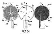
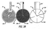
図3Aと図3Bで図示する支持組立構造体は、ヒータと熱センサとを支持する複数の層状要素を含んでいる。これらの層状要素は、複数の領域と、この領域の間に層状要素を貫通して形成されたスリットである細長い開口とを有しており、スリットはプローブの柔軟性を高めている。これらのスリットは、領域をそれぞれ独立的に屈曲させることができる。 The support assembly structure illustrated in FIGS. 3A and 3B includes a plurality of layered elements that support the heater and the thermal sensor. These layered elements have a plurality of regions and an elongated opening which is a slit formed through the layered element between the regions, and the slits enhance the flexibility of the probe. These slits can bend each region independently.
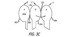
図3Aと図3Bで図示するように、支持組立体500は、柔軟な基部を含む。好適には、支持組立体500は、複数の連結された区画(セクション)を含むように形成された、柔軟な断熱材のシートを含む。例えば、同一径である円盤部502、504及び506を備えた3つの連結されたパドル(櫂形)形状の区画が形成されて整合(位置合わせ)される。円盤部502、504及び506の中心は、一直線上に並べられる。各々の円盤部は、一本以上の導線を支持するためのタブ(つまみ部)になるようにその形状が移行している。タブは、それぞれの符号503、505及び507で示されている。各円盤部の内側の周縁部は、それぞれの隣接する周縁部と連結されており、その連結点は、内側の円の周囲の接線が各円盤部の中心を整合させている線と交差する点である。よって、外側の円盤部502の内側周縁部は、内側の円盤部504の周縁部と、点509で連結されて連続的に構成されており、外側の円盤部506の内側周縁部は、内側の円盤部504の周縁部と点511で連結されて連続的に構成されている。点511は、内側の円盤部504の周縁部の点509に対して、直径方向の反対側にある。各円盤部は、2つの対面する主要な側面(主要面)を有する。外側の円盤部502は、主要面AとBを有しており、内側の円盤部504は主要面CとDを有しており、外側の円盤部506は主要面EとFを有している。主要面A、D及びEは支持組立体500の同じ一側面にあり、主要面B、C、Fはその反対側の側面である。それぞれの区画は、円周の周縁部からそれぞれの円盤部の中心方向に延びる放射状のスリット513のパターン(配列)によって、くさび形の領域を円形に配列した形態に分割されている。スリット513は、各円盤部の分割されていない中央部にまで延びている。これらスリットのパターンはそれぞれ同型であり、それぞれの区画のスリットは、その区画が折り畳まれて重ね合わされると他の区画のスリットと整合する。 As illustrated in FIGS. 3A and 3B, the
図3Aと図3Bで示すように、ヒータ514は主要面Aで支持されている。好適には、ヒータ514は、エッチングされた銅のトレースパターン(線の所定の配列)で構成される。くさび形のそれぞれの領域は、それぞれ、ヒータ514に対応するくさび形領域515を含んでいる。ヒータの熱容量を最大化するためにヒータのトレースパターンは各領域で一連のつづら折り形状(ジグザク形状)で記載(作成)されており、領域と領域の間の連結は、区画内のスリットではない中央部を越えた連結となっている。エッチングは、タブ503上のヒータのための導線及びピンの形成を含んでいる。エッチングは、さらに、主要面A、C及びEの周縁において露出した絶縁材で構成される円環の形成を含む。主要面C上の円環の内側の銅フィルムの円盤部は、熱電対の一要素として使用できる。例えば、熱電対の連結部508は、必須ではないが好適には、主要面Cの中心または中心付近で、絶縁されたクロメルワイヤ(クロムとニッケルの合金製の導線)の一端部を銅フィルムにハンダ付け、ろう付け、または溶接することによって構成される。クロメルワイヤの他端はハンダ付け、ろう付けまたは溶接によってタブ505に取り付けられたクロメル電極に接続される。他の熱電対の連結部510は、主要面Eで同様に構成される。銅は主要面B、D及びFからエッチング除去されるためそれら表面には銅は存在しない。 As shown in FIGS. 3A and 3B, the
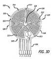
ヒータと熱電対の連結部とがこのように形成されて、支持組立体500は、図3Cで示すようにZ型に折り畳まれる。好適には、区画502と504とは点509で主要面BとCを旋回させることで折り畳まれ、区画504と506とは点511で主要面DとEを旋回させることで折り畳まれる。折り畳まれた状態の支持組立体は、図3Dの平面図にて図示されている。この点に関して、支持組立体500は、好適には、ヒータを組立体の上部とし主要面Fを構造体の底部として配置することによって、深部組織の温度表示が得られる身体上の箇所に対して、方向決めされている(指向されている)。この点で、タブ503、505及び507は、全ての導線とピンとを、合成された複合タブ520の片側に配置するように折り畳むことで整合される。必須ではないが好適には、複合タブ520は、位置合わせされたピンが主要面Aのヒータと同じ方向に向くように方向決めされる。下の表1はピンの割り当てを示す。表の中の下方の熱電対は、主要面Eに存在し、上方の熱電対は主要面Cに存在する。複合タブ520の接続は、熱センサとヒータのそれぞれに電気的接続(アクセス)を提供する。圧縮コネクタを、複合タブに取り付けることが可能である。 The heater and the thermocouple connection are formed in this manner, and the

図3Dにて平面図で示されているパドル形状の支持組立体500は、上面側が示されている。いわば、温度を測定する皮膚領域とは接触しない側が示されている。上面側でヒータ514は支持組立体500の中央部526を中心としている。ヒータの領域は風車状のパターン(配列)を形成している。風車の個々の羽根は、支持組立体500の中央部526から周辺部528に向かって広がっている。銅線(銅のトレース)の風車形の配置は、支持組立体500内にくさび形のヒータ領域529を規定(定義)している。それぞれの領域は、風車の羽根形の線と、線の下側に存在する支持組立体構造の多少厚みを増したくさび形の部分とを含む。スリット513は支持組立体構造を貫通して整合しており、基部と熱抵抗の層を含んで支持組立体の構成要素を完全に通過して延びている。スリットは領域を互いに対して独立的に動かし、支持組立体500に追加の柔軟性を付与する。 The paddle-shaped
スリット入りの複数の領域の支持構造に係る代替的な実施形態が、図3Eと図3Fで図示されている。複数の領域のヒータ534は、部分円形あるいは弧状である線で形成されている。これらの線は、支持組立体500の加熱されない中央部536から周縁部538にかけて、半径が増加している。熱電対の連結部508と連結部510とは上記で開示したように構成される。部分円形または弓形形状のスリット542が、支持組立体の連結された区画を貫通して形成されている。これらの区画が図3Cで示すように折り畳まれると、これらスリット542は整合し、基部と熱抵抗の層を含む支持組立体の構成要素を完全に通過して延びている。スリット542は円盤部と同心であり、それらの端部で相互に整合しており、支持組立体500における、スリットが入っていない、くさび形状の部分544を規定する。スリットは、支持組立体500の部分円形のヒータ領域546を規定するように、ヒータの線の間に配置されている。それぞれの領域546は、部分円形のヒータの線と、それら線の下側の多少厚みが増している部分円形部とを含んでいる。スリット542は部分円形のヒータ領域を独立的に動かし、これにより支持組立体に追加の柔軟性を付与する。ピンは、表1のようにタブに割り当てられる。 An alternative embodiment for a slitted multi-region support structure is illustrated in FIGS. 3E and 3F. The
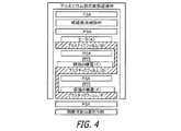
上述の本発明の実施形態に従った支持組立体を備えるDTTプローブ構造体の最終構造が、図4で示されている。折り畳まれていない状態の構造では、3つの円形の円盤部と6つの表面領域とが存在する。支持組立品を折り畳むことで形成された層状要素の構成は、以下のとおりである。
主要面Aは、電気ヒータである。
主要面Bは、プラスチックフィルムである。
主要面Cは、熱センサを支持する銅層である。
主要面Dは、プラスチックフィルムである。
主要面Eは、熱センサを支持する銅層である。
主要面Fは、プラスチックフィルムである。The final structure of a DTT probe structure comprising a support assembly according to the above-described embodiment of the present invention is shown in FIG. In the unfolded structure, there are three circular disc parts and six surface regions. The structure of the layered element formed by folding the support assembly is as follows.
The main surface A is an electric heater.
The main surface B is a plastic film.
The main surface C is a copper layer that supports the thermal sensor.
The main surface D is a plastic film.
The main surface E is a copper layer that supports the thermal sensor.
The main surface F is a plastic film.
組み立てられたRTTプローブは、組み立て中にプローブの構造に追加される、追加的な層状要素を含むことができる。例えば感圧接着剤(PSA)の層を折り畳まれた区画と上下の主要面との間に配置することが可能であり、絶縁層はヒータ上にあるPSA層の上に配置することができ、さらにPSA層は絶縁層の上側に配置することができる。さらに剥離可能な裏打ち材(リリースライナー)を底部のPSA層上に提供することができ、アルミニウム製の放熱遮蔽材をPSA層の上層で支持することができる。 The assembled RTT probe can include additional layered elements that are added to the structure of the probe during assembly. For example, a layer of pressure sensitive adhesive (PSA) can be placed between the folded compartment and the top and bottom major surfaces, and the insulating layer can be placed on the PSA layer on the heater, Furthermore, the PSA layer can be disposed above the insulating layer. Further, a peelable backing material (release liner) can be provided on the bottom PSA layer, and an aluminum heat radiation shielding material can be supported by the upper layer of the PSA layer.
図4で示すように、図3Dと図3Fに示す支持組立体の実施形態は、支持組立体の区画の上面の中央部に取り付けられた熱センサTC(好適には熱電対)を含む。熱センサが折り畳まれた円盤部の中央部に取り付けられると、それらは中央を通る中央軸に沿って垂直に整合されている。 As shown in FIG. 4, the embodiment of the support assembly shown in FIGS. 3D and 3F includes a thermal sensor TC (preferably a thermocouple) attached to the center of the upper surface of the compartment of the support assembly. When the thermal sensors are attached to the center of the folded disc, they are vertically aligned along a central axis through the center.
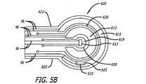
図5Aと図5Bで示す第三の支持組立体の実施形態は、熱センサがその上に離れた位置関係で配置されている階層に分けられている、複数の連結された区画に形成された単一の基部層を備えた構造を特徴とする。好適には、熱センサは、半径方向に離れた位置関係で別々の同心である支持部材上に配置されている。好適には、基部は、その上に入れ子形態で提供された部分円形状のヒータを備えているパドル形状を有する。少なくとも2つのセンサを支持する支持区画が、基部とは分離された断熱層によって分離される。パドル形状である円盤部の外側に突き出ており、ヒータ及び熱センサのための導線を支持する導線支持用タブを利用することが望ましい。 The third support assembly embodiment shown in FIGS. 5A and 5B is formed in a plurality of connected compartments that are divided into hierarchies on which thermal sensors are arranged in a spaced apart relationship. Features a structure with a single base layer. Preferably, the thermal sensors are arranged on separate concentric support members in a radially spaced relationship. Preferably, the base has a paddle shape with a partial circular heater provided in a nested form thereon. A support compartment supporting at least two sensors is separated by a thermal insulation layer separated from the base. It is desirable to use a wire support tab that protrudes to the outside of the paddle-shaped disk portion and supports the wires for the heater and thermal sensor.
図5Aと図5Bは、円盤部620とタブ621を備えたパドル形状部として形成された柔軟な二面の基部602を平面図で図示している。同心の部分円形状のヒータの線613と615とは基部602の片面に形成される。切り込み領域625(ノッチエリア625)が、外側ヒータの線613の内側端部に延びている。熱センサ610と612は、基部602にヒータの線と同じ側面上に配置される。熱センサ612は実質的に円盤部620の中央部619に位置する。熱センサ610は最外側のヒータの線613内に形成された切り込み領域625内に位置する。導線及びピンのための線はタブ621に沿って延びる。基部602は、基部を通って延びるパドル形状のスリット630を形成するために型抜き処理(ダイカット処理)されている。第一のスリットは、ヒータ線613と615の間の部分円形領域と、タブ621に沿って分離された細長い領域とを有している。もう一つのスリットは最も内側ヒータの線615と中央部619との間に部分円形領域を有しており、タブ621に沿った分離された細長い領域をさらに含む。 5A and 5B illustrate in plan view a flexible two-
図5Aで最良のものを示すように、パドル形状のスリット630は、複数の層に分離することが可能な、支持組立体の分離可能な区画604、606及び608を規定する。好適には、これらの区画は、区画608が区画604と606の間に配置され、区画606と608はヒータ615が熱センサ612の上方に位置するように配置され、ヒータ613と熱センサ610は熱センサ612の下方に位置するように配置される。基部から分離しており、垂直方向の分離を提供し、熱抵抗を熱センサ610と熱センサ612の間に挿入する断熱材の少なくとも1つの層状要素617は、区画604と606の間に挿入される。必要ならば、基部602から分離可能な断熱材の第二の層状要素623が、区画608と606の間に挿入されて垂直方向の分離を提供する。また、熱抵抗を熱センサ612とヒータ615との間に挿入する。絶縁材640の柔軟な層状要素が、感圧接着剤にてヒータ613上にて区画606に提供され、剥離可能な裏打ち材を備えた患者側接着剤642の層状要素が、区画604の底部に適用される。 As best shown in FIG. 5A, paddle-shaped
ここで開示する任意の実施形態に従った支持組立体は、例えばKapton(登録商標)ポリイミド、Kaptrex(登録商標)ポリイミド、ポリエステルまたは他の柔軟な断熱材のフィルムのようなプラスチックフィルムの両面シートによって構築できる。このシートはその片面あるいは両面を銅フィルムコーティングでき、例えばヒータ、銅製円盤部、銅製導線及びピンのような種々な要素が、支持組立体が折り畳まれるか又は分離される前にフォトエッチング加工できる。その後、シートは必要な形状に型抜き処理され、前述のように折り畳まれるか分離される。例えば金またはアルミのような高熱伝導性を備えた他の金属も使用できるが銅が好適である。なぜなら銅はT型熱電対の一方を構成できるからである。しかし、他のタイプの熱電対も利用可能であり、もし平衡状態のRTD、サーミスタ、及び/又は点連結熱電対といった他の熱センサが利用されて温度が測定されるなら、金属フィルムを全く利用しないことも可能である。クロメルの線と導線とは、蒸着またはピーニングにより形成できる。 The support assembly according to any embodiment disclosed herein may be, for example, by a double-sided sheet of plastic film, such as Kapton® polyimide, Kaptrex® polyimide, polyester or other flexible insulation film. Can be built. The sheet can be coated with copper film on one or both sides, and various elements such as heaters, copper discs, copper conductors and pins can be photoetched before the support assembly is folded or separated. The sheet is then stamped into the required shape and folded or separated as described above. Other metals with high thermal conductivity such as gold or aluminum can be used, but copper is preferred. This is because copper can constitute one of the T-type thermocouples. However, other types of thermocouples can also be used, and if other thermal sensors such as equilibrium RTDs, thermistors, and / or point-coupled thermocouples are used to measure temperature, the metal film is used entirely. It is also possible not to. Chromel wires and conductors can be formed by vapor deposition or peening.
使い捨てタイプのDTTプローブは、前述の支持組立体の実施形態を利用して容易及び安価に製造できる。使い捨て仕様はDTTプローブの商業化を可能にする。また1回利用するだけのプローブは患者間の交差伝染の可能性を制限し、さらに多くの患者が周手術期の体温測定の有効性を享受できる。 The disposable DTT probe can be easily and inexpensively manufactured using the above-described support assembly embodiment. Disposable specifications allow commercialization of DTT probes. Also, a single use probe limits the possibility of cross-contamination between patients, and more patients can enjoy the effectiveness of perioperative body temperature measurements.
本発明は現在のところ好適と考えられる実施形態に基づいて解説されているが、本発明の精神から逸脱せずにそれらを様々に改良することは可能である。従って本発明は以下の「請求の範囲」によってのみ制限される。 While the invention has been described in terms of the presently preferred embodiments, various modifications can be made without departing from the spirit of the invention. Accordingly, the invention is limited only by the following claims.
Claims (19)
Translated fromJapanese二つの側面を有する基部と、
前記基部に規定された複数の区画であって、それぞれの区画は少なくとも一つの隣接した区画に、両方の区画に共通となる周縁部の位置で結合されている複数の区画と、
二つの熱センサであって、各々が隣接する二つの区画の対応する一方の上に支持されている二つの熱センサと、
更に別体の区画の上に支持されているヒータと、
前記複数の区画に設けられた複数のスリットのパターンと、
を備えていることを特徴とする深部組織用温度プローブのための支持組立体。A support assembly for a deep tissue temperature probe comprising:
A base having two sides;
A plurality of compartments defined in the base, each compartment being coupled to at least one adjacent compartment at a peripheral edge position common to both compartments;
Two thermal sensors, each of which is supported on a corresponding one of two adjacent compartments;
And a heater supported on a separate compartment;
A plurality of slit patterns provided in the plurality of sections;
A support assembly for a deep tissue temperature probe.
前記二つの熱センサの他方は、前記二つの隣接する区画の他方の表面に取り付けられており、
前記スリットのパターンは、前記ヒータの中の複数の領域を規定しており、前記複数の区画は、共通するパターンの前記スリットが整合されて、全ての前記区画を貫通して開口した状態となるように折り畳まれて重ね合わされることを特徴とする請求項1記載の支持組立体。One of the two thermal sensors is attached to one surface of the two adjacent compartments;
The other of the two thermal sensors is attached to the other surface of the two adjacent compartments;
The slit pattern defines a plurality of regions in the heater, and the plurality of sections are in a state where the slits of the common pattern are aligned and open through all the sections. The support assembly according to claim 1, wherein the support assembly is folded and overlapped.
折り畳まれて重ね合わされた三つの区画を備えた柔軟な基部と、
前記折り畳まれて重ね合わされた三つの区画を通して規定された複数の領域と、
互いに隣接する二つの前記区画において支持されている二つの熱センサと、
前記二つとは異なる区画において支持されており、前記領域のそれぞれに配置されたヒータ領域を含んでいるヒータと、
を備えていることを特徴とする支持組立体。A support assembly for a deep tissue temperature probe comprising:
A flexible base with three compartments folded and superimposed;
A plurality of regions defined through the three folded and superimposed sections;
Two thermal sensors supported in two said compartments adjacent to each other;
A heater that is supported in a section different from the two and includes a heater region disposed in each of the regions;
A support assembly comprising:
二つの側面を有する基部を備えており、
前記基部は部分円形状の周縁部を備えており、
前記基部は部分円形状のスリットを備えており、前記スリットは、前記周縁部に配置された少なくとも二つの部分円形状の支持区画を規定しており、
前記基部の同一の側面には、それぞれ前記少なくとも二つの部分円形の支持区画のそれぞれに支持されている二つの熱センサが提供されており、
前記基部とは分離した状態で前記支持区画の間に挟まれている断熱材の層を更に備えていることを特徴とする温度装置。A temperature device with a support structure,
A base having two sides,
The base includes a partial circular peripheral edge,
The base comprises a partial circular slit, the slit defining at least two partial circular support sections disposed on the peripheral edge;
On the same side of the base, two thermal sensors are provided, each supported on each of the at least two partial circular support sections,
A temperature device further comprising a layer of heat insulating material sandwiched between the support sections in a state separated from the base.
前記第三の支持区画上に設けられたヒータの線と、
前記基部とは分離した状態で前記第一の支持区画と前記第二の支持区画との間に配置された断熱材層とを更に備えていることを特徴とする請求項14記載の温度装置。A third support section disposed concentrically between the first support section and the second support section;
A heater wire provided on the third support section;
The temperature device according to claim 14, further comprising a heat insulating material layer disposed between the first support section and the second support section in a state separated from the base.
温度プローブの要素を支持する柔軟な基部を含んでなる支持組立体を備えており、前記支持組立体が、複数領域の、ヒータと、熱センサと、熱抵抗と、を含む層状要素を備えていることを特徴とする温度装置。A temperature device,
A support assembly comprising a flexible base for supporting elements of a temperature probe, said support assembly comprising layered elements including a plurality of regions of heaters, thermal sensors, and thermal resistances A temperature device characterized by comprising:
前記支持組立体は複数の層状要素を含んでおり、
第一の層状要素は防護ヒータを支持しており、第二の層状要素は第一の熱センサを支持しており、第三の層状要素は該第一の熱センサから少なくとも半径方向に離れている熱センサを支持していることを特徴とする温度装置。A temperature device comprising a support assembly having a flexible base for supporting elements of the temperature probe;
The support assembly includes a plurality of layered elements;
The first layered element supports the protective heater, the second layered element supports the first thermal sensor, and the third layered element is at least radially away from the first thermal sensor. A temperature device that supports a thermal sensor.
Applications Claiming Priority (3)
| Application Number | Priority Date | Filing Date | Title |
|---|---|---|---|
| US21274909P | 2009-04-15 | 2009-04-15 | |
| US61/212,749 | 2009-04-15 | ||
| PCT/US2010/001104WO2010120360A1 (en) | 2009-04-15 | 2010-04-14 | Deep tissue temperature probe constructions |
Publications (1)
| Publication Number | Publication Date |
|---|---|
| JP2012524261Atrue JP2012524261A (en) | 2012-10-11 |
Family
ID=42312859
Family Applications (1)
| Application Number | Title | Priority Date | Filing Date |
|---|---|---|---|
| JP2012505882APendingJP2012524261A (en) | 2009-04-15 | 2010-04-14 | Deep tissue temperature probe structure |
Country Status (5)
| Country | Link |
|---|---|
| US (1) | US9310257B2 (en) |
| EP (2) | EP2419006B1 (en) |
| JP (1) | JP2012524261A (en) |
| CN (1) | CN102458232A (en) |
| WO (1) | WO2010120360A1 (en) |
Families Citing this family (24)
| Publication number | Priority date | Publication date | Assignee | Title |
|---|---|---|---|---|
| JP2012524261A (en) | 2009-04-15 | 2012-10-11 | アリザント ヘルスケア インク. | Deep tissue temperature probe structure |
| JP2012524262A (en) | 2009-04-15 | 2012-10-11 | アリザント ヘルスケア インク. | Deep tissue temperature probe structure |
| US8226294B2 (en)* | 2009-08-31 | 2012-07-24 | Arizant Healthcare Inc. | Flexible deep tissue temperature measurement devices |
| US8292495B2 (en)* | 2010-04-07 | 2012-10-23 | Arizant Healthcare Inc. | Zero-heat-flux, deep tissue temperature measurement devices with thermal sensor calibration |
| US8292502B2 (en) | 2010-04-07 | 2012-10-23 | Arizant Healthcare Inc. | Constructions for zero-heat-flux, deep tissue temperature measurement devices |
| FR2966927B1 (en)* | 2010-11-02 | 2013-08-09 | Vigilio | IMPROVED BODY THERMOMETER |
| BR112013020849A2 (en)* | 2011-02-16 | 2018-05-29 | Arizant Healthcare Inc | zero heat flow temperature device, temperature measurement device, temperature measurement system, body temperature measurement methods |
| EP2686651B1 (en)* | 2011-03-18 | 2017-05-03 | Augustine Biomedical and Design, LLC | Non-invasive core temperature sensor |
| US9354122B2 (en) | 2011-05-10 | 2016-05-31 | 3M Innovative Properties Company | Zero-heat-flux, deep tissue temperature measurement system |
| JP6349713B2 (en) | 2013-12-13 | 2018-07-04 | オムロン株式会社 | Internal temperature sensor |
| EP3164064A1 (en) | 2014-07-03 | 2017-05-10 | Koninklijke Philips N.V. | Medical electrode |
| CN104434048B (en)* | 2014-12-01 | 2016-08-24 | 电子科技大学 | A kind of human body deep tissue temperature measuring instrument and measuring method |
| JP6468398B2 (en)* | 2016-04-22 | 2019-02-13 | 株式会社村田製作所 | Deep thermometer |
| US10856741B2 (en)* | 2016-12-14 | 2020-12-08 | Vital Connect, Inc. | Core body temperature detection device |
| CH713267A1 (en)* | 2016-12-21 | 2018-06-29 | Greenteg Ag | Sensor unit for a portable computer system and integration of the sensor unit in the housing of the computer system. |
| US11406326B2 (en) | 2017-03-14 | 2022-08-09 | Mordehy HABER | Method, system and device for noninvasive core body temperature monitoring |
| US20210038084A1 (en)* | 2018-05-02 | 2021-02-11 | 3M Innovative Properties Company | Core body temperature device and system |
| US11872156B2 (en) | 2018-08-22 | 2024-01-16 | Masimo Corporation | Core body temperature measurement |
| US12220207B2 (en) | 2019-02-26 | 2025-02-11 | Masimo Corporation | Non-contact core body temperature measurement systems and methods |
| CN116337278A (en)* | 2019-03-14 | 2023-06-27 | 生物数据银行股份有限公司 | Temperature sensor unit and in-vivo thermometer |
| WO2020227641A1 (en)* | 2019-05-08 | 2020-11-12 | Baxter International Inc. | Patch-based physiological sensor |
| US20230129156A1 (en)* | 2021-10-25 | 2023-04-27 | Hyperthermia Cancer Institute Llc | Non-invasive thermometry apparatus |
| CN119317391B (en)* | 2022-05-27 | 2025-09-16 | 世美特株式会社 | Deep temperature measuring device and deep temperature measuring method |
| CN116275763B (en)* | 2023-05-22 | 2023-08-18 | 中国航发四川燃气涡轮研究院 | Hot wire welding method and device for one-dimensional probe of hot wire anemometer |
Family Cites Families (146)
| Publication number | Priority date | Publication date | Assignee | Title |
|---|---|---|---|---|
| US1363259A (en) | 1919-09-19 | 1920-12-28 | Mills David Hirst | Thermometer-cover |
| US1526641A (en) | 1921-08-09 | 1925-02-17 | Pacific Fire Extinguisher Comp | Thermopile |
| US1638943A (en) | 1922-09-27 | 1927-08-16 | Westinghouse Electric & Mfg Co | Thermoelectric cell and method of making the same |
| US1528383A (en) | 1923-06-11 | 1925-03-03 | Schmidt Ernst | Device for the measurement of heat |
| US2378804A (en) | 1940-05-13 | 1945-06-19 | Honeywell Regulator Co | Thermocouple |
| US2381819A (en) | 1942-08-19 | 1945-08-07 | Alltools Ltd | Thermocouple |
| US2629757A (en) | 1943-11-08 | 1953-02-24 | Warren Dunham Foster | Method of construction of sensitive thermopiles |
| US2519785A (en) | 1944-08-14 | 1950-08-22 | Okolicsanyi Ferenc | Thermopile |
| US2807657A (en) | 1953-12-21 | 1957-09-24 | North American Aviation Inc | Method of making a thermopile |
| US2969141A (en) | 1957-06-17 | 1961-01-24 | Eugene M Katzin | Thermometer cover |
| US3099575A (en) | 1959-10-20 | 1963-07-30 | Engelhard Ind Inc | Thermocouple |
| US3099923A (en) | 1960-01-18 | 1963-08-06 | Theodor H Benzinger | Thermopile switching systems |
| US3238775A (en) | 1962-01-02 | 1966-03-08 | Lockheed Aircraft Corp | Heat flux responsive device |
| FI43701B (en) | 1962-02-14 | 1971-02-01 | H Jaerund | |
| SE303009B (en) | 1962-12-07 | 1968-08-12 | Berger J Welin | |
| US3427209A (en) | 1965-05-18 | 1969-02-11 | Armstrong Cork Co | Quick response heat-sensing element |
| US3367182A (en) | 1965-06-02 | 1968-02-06 | Nasa Usa | Heat flux measuring system |
| US3301394A (en) | 1965-10-15 | 1967-01-31 | Medical Supply Company | Sheath package |
| US3581570A (en) | 1967-09-05 | 1971-06-01 | Garrett Corp | Thermal radiation sensor |
| US3469685A (en) | 1967-10-23 | 1969-09-30 | Medical Supply Co | Sheath package and method of application |
| US3767470A (en) | 1968-02-19 | 1973-10-23 | F Hines | Thermally compensated heat flow sensors |
| US3607445A (en) | 1968-02-19 | 1971-09-21 | Rdf Corp | Thermal apparatus |
| US3552558A (en) | 1968-06-11 | 1971-01-05 | George W Poncy | Sterile package for clinical thermometers and the like and method of making it |
| GB1354874A (en)* | 1970-05-01 | 1974-06-05 | Nat Res Dev | Temperature measurement |
| US3942123A (en) | 1970-06-15 | 1976-03-02 | Ivac Corporation | Electronic measurement system |
| US3809230A (en) | 1970-10-05 | 1974-05-07 | Johnson & Johnson | Sheath-package and method |
| US3720103A (en) | 1970-11-03 | 1973-03-13 | Cornell Aeronautical Labor Inc | Heat flux measuring system |
| GB1415644A (en) | 1971-11-18 | 1975-11-26 | Johnson Matthey Co Ltd | Resistance thermometer element |
| US3833115A (en) | 1972-02-24 | 1974-09-03 | R Schapker | Clinical probe and disposable sheath |
| US3877463A (en) | 1973-07-02 | 1975-04-15 | Massachusetts Inst Technology | Thermal method and device for the differential diagnosis of human tumors and circulatory disorders |
| US4022063A (en) | 1974-10-15 | 1977-05-10 | Rwb Labs | Electromechanical digital thermometer |
| US4024312A (en) | 1976-06-23 | 1977-05-17 | Johnson & Johnson | Pressure-sensitive adhesive tape having extensible and elastic backing composed of a block copolymer |
| US4142631A (en) | 1977-05-09 | 1979-03-06 | Brandriff Robert C | Sterile thermometer sheath |
| US4190058A (en) | 1978-05-22 | 1980-02-26 | Arden Industries, Inc. | Device for use in early detection of breast cancer |
| DE2835602C2 (en) | 1978-08-14 | 1980-09-04 | Jochen Dr.-Ing. 8035 Gauting Edrich | Method and device for non-contact subcutaneous body temperature distribution determination |
| JPS5529794U (en) | 1978-08-18 | 1980-02-26 | ||
| US4253469A (en) | 1979-04-20 | 1981-03-03 | The Narda Microwave Corporation | Implantable temperature probe |
| US4275741A (en) | 1979-08-13 | 1981-06-30 | Jochen Edrich | Procedure for noncontacting measurement of subcutaneous temperature distributions |
| US4347854A (en) | 1979-10-15 | 1982-09-07 | Gosline Scott P | Bipolar temperature measuring apparatus |
| DE3100610C2 (en) | 1981-01-12 | 1983-07-07 | Vladimir Dr.-Ing. Blazek | Measuring device for the non-invasive determination of venous or arterial outflow and flow disturbances |
| JPS6211395Y2 (en) | 1981-05-16 | 1987-03-18 | ||
| WO1983001510A1 (en) | 1981-10-13 | 1983-04-28 | Baumbach, Per, Lennart | Method for transcutaneous measurement of a blood parameter and an electrochemical measuring electrode device for carrying out the method |
| SE442063B (en) | 1982-04-15 | 1985-11-25 | Minitube Ab | FEVER thermowell |
| US4592000A (en) | 1982-06-24 | 1986-05-27 | Terumo Corporation | Electronic clinical thermometer, and method of measuring body temperature |
| JPS58225327A (en) | 1982-06-24 | 1983-12-27 | Sharp Corp | Electronic clinical thermometer |
| US4541734A (en) | 1982-06-24 | 1985-09-17 | Terumo Kabushiki Kaisha | Electronic clinical thermometer, and method of measuring body temperature |
| US4574359A (en) | 1982-12-21 | 1986-03-04 | Terumo Kabushiki Kaisha | Electronic clinical thermometer, and method of measuring body temperature |
| DE3346285A1 (en) | 1982-12-21 | 1984-10-11 | Terumo K.K., Tokio/Tokyo | ELECTRONIC CLINICAL THERMOMETER AND METHOD FOR MEASURING BODY TEMPERATURE |
| JPS60201224A (en) | 1984-03-27 | 1985-10-11 | Kyushu Daigaku | Multilayered thin-film heat conduction gauge |
| DE3527942A1 (en) | 1985-08-03 | 1987-02-12 | Fraunhofer Ges Forschung | METHOD AND DEVICE FOR MEASURING THE BODY CORE TEMPERATURE OF BIOLOGICAL MEASURING OBJECTS |
| US4669049A (en) | 1985-10-08 | 1987-05-26 | Mon-A-Therm, Inc. | Temperature measuring instrument and adapter for same |
| FR2588962B1 (en) | 1985-10-23 | 1988-01-15 | Centre Nat Rech Scient | SENSOR FOR MEASURING THE THERMAL CONDUCTIVITY OF MATERIALS |
| US4859078A (en) | 1986-02-07 | 1989-08-22 | Massachusetts Institute Of Technology | Apparatus for the non-invasive measurement of thermal properties and perfusion rates of biomaterials |
| JPH0625700B2 (en) | 1986-03-04 | 1994-04-06 | テルモ株式会社 | Electronic thermometer |
| US4747413A (en) | 1986-11-07 | 1988-05-31 | Bloch Harry S | Infant temperature measuring apparatus and methods |
| WO1988004040A1 (en) | 1986-11-26 | 1988-06-02 | Terumo Kabushiki Kaisha | Electronic clinical thermometer |
| JPH0795004B2 (en) | 1986-12-24 | 1995-10-11 | テルモ株式会社 | Body temperature measuring device |
| JPH0638062B2 (en) | 1987-04-08 | 1994-05-18 | テルモ株式会社 | Automatic inspection device for predictive temperature measuring equipment |
| JPS63253223A (en) | 1987-04-09 | 1988-10-20 | Terumo Corp | Temperature measuring instrument |
| US5002057A (en) | 1987-12-28 | 1991-03-26 | G. L. Spaeth | Cover for prism of an applanation tonometer and method of application thereof |
| US5149200A (en) | 1988-08-25 | 1992-09-22 | Terumo Kabushiki Kaisha | Temperature measuring probe and electronic clinical thermometer equipped with same |
| US5178468A (en) | 1988-08-25 | 1993-01-12 | Terumo Kabushiki Kaisha | Temperature measuring probe and electronic clinical thermometer equipped with same |
| JP2675344B2 (en) | 1988-08-25 | 1997-11-12 | テルモ株式会社 | Temperature measuring probe |
| US5199436A (en) | 1988-12-06 | 1993-04-06 | Exergen Corporation | Radiation detector having improved accuracy |
| US4955380A (en) | 1988-12-15 | 1990-09-11 | Massachusetts Institute Of Technology | Flexible measurement probes |
| CH678579A5 (en) | 1989-04-24 | 1991-09-30 | Mettler Toledo Ag | |
| US5050612A (en) | 1989-09-12 | 1991-09-24 | Matsumura Kenneth N | Device for computer-assisted monitoring of the body |
| US5062432A (en) | 1990-05-09 | 1991-11-05 | Labelle Industries, Inc. | Method and apparatus for monitoring personal core temperature |
| CA2098313C (en) | 1990-12-12 | 2001-06-19 | Gary J. O'hara | Infrared thermometer utilizing calibration mapping |
| US5516581A (en) | 1990-12-20 | 1996-05-14 | Minnesota Mining And Manufacturing Company | Removable adhesive tape |
| US5263775A (en) | 1991-02-01 | 1993-11-23 | Aetrium, Inc. | Apparatus for handling devices under varying temperatures |
| US5172979A (en) | 1991-11-29 | 1992-12-22 | Texaco Inc. | Heater tube skin thermocouple |
| GB2266771B (en) | 1992-04-22 | 1995-11-01 | Robert Lendrum Fyfe | Heatflow balancing thermometer |
| JP3375995B2 (en) | 1992-11-25 | 2003-02-10 | ミネソタ マイニング アンド マニュファクチャリング カンパニー | Medical temperature sensor |
| US5255979A (en) | 1993-02-01 | 1993-10-26 | Ferrari R Keith | Medical temperature probe cover |
| US6231962B1 (en) | 1993-08-31 | 2001-05-15 | 3M Innovative Properties Company | Removable foam adhesive tape |
| FI96066C (en) | 1994-03-24 | 1996-04-25 | Polar Electro Oy | Method and apparatus for determining the internal temperature and coefficient of heat conduction in a structure |
| US5483190A (en) | 1994-12-01 | 1996-01-09 | United Technologies Corporation | Floating voltage controlled thermistor/platinum probe emulator |
| US5725308A (en) | 1994-12-23 | 1998-03-10 | Rtd Technology, Inc. | Quick registering thermometer |
| JPH08211000A (en) | 1995-02-06 | 1996-08-20 | Terumo Corp | Thermal physical property measuring device |
| US6001471A (en) | 1995-08-11 | 1999-12-14 | 3M Innovative Properties Company | Removable adhesive tape with controlled sequential release |
| US5990412A (en) | 1996-05-07 | 1999-11-23 | Vatell Corporation | Differential thermopile heat flux transducer formed by depositing metals and non-metals from liquids onto a substrate |
| US6014890A (en) | 1996-09-25 | 2000-01-18 | Breen; Peter H. | Fast response humidity and temperature sensor device |
| US5884235A (en) | 1996-12-17 | 1999-03-16 | Integrated Systems, Inc. | Non-contact, zero-flux temperature sensor |
| IL120758A (en) | 1997-05-01 | 2000-02-29 | Medisim Ltd | High speed accurate temperature measuring device |
| US6278051B1 (en) | 1997-10-09 | 2001-08-21 | Vatell Corporation | Differential thermopile heat flux transducer |
| US5993698A (en) | 1997-11-06 | 1999-11-30 | Acheson Industries, Inc. | Electrical device containing positive temperature coefficient resistor composition and method of manufacturing the device |
| US6179159B1 (en) | 1998-01-26 | 2001-01-30 | Mariruth D. Gurley | Communicable disease barrier digit cover and dispensing package therefor |
| AU4899199A (en) | 1998-05-20 | 1999-12-06 | Consiglio Nazionale Delle Ricerche | Heat flux control method and apparatus for calorimetry, adiabatic shielding, precise temperature setting and the like |
| US6224543B1 (en) | 1998-05-21 | 2001-05-01 | Adroit Medical Systems, Inc. | Non-latex inverted sheath device |
| EP1112018A1 (en) | 1998-09-09 | 2001-07-04 | U.S. Army Institute of Surgical Research | Disposable pulse oximeter assembly and protective cover therefor |
| US6292685B1 (en) | 1998-09-11 | 2001-09-18 | Exergen Corporation | Temporal artery temperature detector |
| US6203191B1 (en) | 1998-10-28 | 2001-03-20 | Speculative Incorporated | Method of junction temperature determination and control utilizing heat flow |
| US6398727B1 (en) | 1998-12-23 | 2002-06-04 | Baxter International Inc. | Method and apparatus for providing patient care |
| US6220750B1 (en) | 1999-03-29 | 2001-04-24 | Yoram Palti | Non-invasive temperature measurement method and apparatus |
| US6355916B1 (en) | 1999-05-18 | 2002-03-12 | Alaris Medical Systems, Inc. | Closed loop system and method for heating a probe |
| US6377848B1 (en) | 1999-08-25 | 2002-04-23 | Vyteris, Inc. | Devices activating an iontophoretic delivery device |
| US6626037B1 (en)* | 1999-09-03 | 2003-09-30 | Denso Corporation | Thermal flow sensor having improved sensing range |
| US6300554B1 (en)* | 1999-09-09 | 2001-10-09 | Metrodyne Microsystem Corp. | Method of fabricating thermoelectric sensor and thermoelectric sensor device |
| IL132549A0 (en) | 1999-10-24 | 2001-03-19 | Medisim Ltd | Method for the production of electronic thermometers and a thermometer produced according to the method |
| US6255622B1 (en) | 1999-10-27 | 2001-07-03 | Hewlett-Packard Company | Electronic device having external surface thermal feedback |
| US6312391B1 (en) | 2000-02-16 | 2001-11-06 | Urologix, Inc. | Thermodynamic modeling of tissue treatment procedure |
| US20020097775A1 (en) | 2000-08-29 | 2002-07-25 | Hechmi Hamouda | Heat sensing device for thermal and skin burn evaluation |
| US6773405B2 (en) | 2000-09-15 | 2004-08-10 | Jacob Fraden | Ear temperature monitor and method of temperature measurement |
| JP3536096B2 (en) | 2000-10-24 | 2004-06-07 | テルモ株式会社 | Deep temperature measuring device |
| GB0103886D0 (en) | 2001-02-16 | 2001-04-04 | Baumbach Per L | Temperature measuring device |
| US6595929B2 (en) | 2001-03-30 | 2003-07-22 | Bodymedia, Inc. | System for monitoring health, wellness and fitness having a method and apparatus for improved measurement of heat flow |
| EP1249691A1 (en) | 2001-04-11 | 2002-10-16 | Omron Corporation | Electronic clinical thermometer |
| US6886978B2 (en) | 2001-06-18 | 2005-05-03 | Omron Corporation | Electronic clinical thermometer |
| DE10139705A1 (en) | 2001-08-11 | 2003-04-03 | Draeger Medical Ag | Device for measuring body temperature |
| JP4157914B2 (en) | 2002-03-20 | 2008-10-01 | 坂野 數仁 | Temperature measuring apparatus and temperature measuring method |
| CA2397102C (en) | 2002-08-07 | 2012-05-29 | Mathis Instruments Ltd. | Direct thermal conductivity measurement technique |
| DE10249853A1 (en) | 2002-10-25 | 2004-05-13 | Liedtke, Rainer K., Dr. | Flexible, plaster-type chip heating system, for thermodynamic control of topical (trans)dermal systems, including supporting matrix, electrical energy source, controlling microprocessor and electric heater |
| US7306283B2 (en) | 2002-11-21 | 2007-12-11 | W.E.T. Automotive Systems Ag | Heater for an automotive vehicle and method of forming same |
| US20050015127A1 (en)* | 2003-04-10 | 2005-01-20 | Bieberich Mark T. | Perioperative warming device |
| FR2858406B1 (en) | 2003-08-01 | 2005-10-21 | Centre Nat Rech Scient | SENSOR, DEVICE AND METHOD FOR MEASURING INTERFACE PRESSURE BETWEEN TWO BODIES |
| US7270476B2 (en) | 2003-08-21 | 2007-09-18 | Omron Healthcare Co., Ltd. | Electronic clinical thermometer with quick temperature estimating device |
| WO2005092177A1 (en) | 2004-03-22 | 2005-10-06 | Bodymedia, Inc. | Non-invasive temperature monitoring device |
| DE102005004933B3 (en) | 2005-02-03 | 2006-08-31 | Dräger Safety AG & Co. KGaA | Device for measuring the body temperature of a living being |
| US7470280B2 (en)* | 2005-02-11 | 2008-12-30 | Arizant Healthcare Inc. | Clinical garment for comfort warming and prewarming |
| US7318004B2 (en) | 2005-04-01 | 2008-01-08 | Cardinal Health 303, Inc. | Temperature prediction system and method |
| DE102005037921B3 (en) | 2005-08-11 | 2006-06-14 | Dräger Medical AG & Co. KG | Temperature measuring device, for patient use, has evaluating means for detecting skin surface temperature from first temperature measured value and determines temperature at skin surface where double temperature sensor is in contact |
| US8032210B2 (en)* | 2005-10-06 | 2011-10-04 | Spinematrix, Inc. | EMG diagnostic system and method |
| DE102005049676B3 (en) | 2005-10-18 | 2006-11-16 | Dräger Medical AG & Co. KG | Method of contact-free determination of body temperature of baby involves using surface temperature at particular selected body location |
| EP2759811A3 (en)* | 2005-10-24 | 2014-09-10 | Heraeus Sensor Technology Gmbh | Flow sensor element and its self-cleaning |
| CN101312688B (en)* | 2005-11-25 | 2010-06-16 | 皇家飞利浦电子股份有限公司 | Biometric sensor |
| JP2007212407A (en) | 2006-02-13 | 2007-08-23 | Kanazawa Univ | Non-heated deep body thermometer and deep body temperature measuring device using the same |
| CA2538940A1 (en)* | 2006-03-03 | 2006-06-22 | James W. Haslett | Bandage with sensors |
| CA2583034C (en) | 2006-03-03 | 2016-01-05 | James W. Haslett | Bandage with sensors |
| US7597668B2 (en)* | 2006-05-31 | 2009-10-06 | Medisim Ltd. | Non-invasive temperature measurement |
| WO2008068665A1 (en)* | 2006-12-06 | 2008-06-12 | Koninklijke Philips Electronics, N.V. | Device for measuring core temperature |
| KR20090103883A (en) | 2006-12-20 | 2009-10-01 | 코닌클리케 필립스 일렉트로닉스 엔.브이. | Device and method for measuring core temperature |
| DE102007002369B3 (en) | 2007-01-17 | 2008-05-15 | Drägerwerk AG & Co. KGaA | Dual temperature sensor for e.g. patient, has sensor units with connections arranged parallel to each other in block and at distance to each other from external surface of block, where distance is formed by layer of insulating material |
| JP2009080000A (en) | 2007-09-26 | 2009-04-16 | Citizen Holdings Co Ltd | Clinical thermometer |
| CN101435727B (en) | 2007-11-12 | 2011-01-26 | 深圳迈瑞生物医疗电子股份有限公司 | Temperature predicting method and apparatus |
| CN102036600B (en) | 2008-05-23 | 2014-08-06 | 皇家飞利浦电子股份有限公司 | Substrate layer suitable for carrying sensors, actuators or electronic components |
| WO2010082102A2 (en) | 2009-01-19 | 2010-07-22 | Koninklijke Philips Electronics, N.V. | Zero heat flux sensor and method of use |
| EP2406604B1 (en) | 2009-03-13 | 2013-05-15 | Koninklijke Philips Electronics N.V. | Zero heat flux temperature sensing device |
| CN106264461A (en) | 2009-04-06 | 2017-01-04 | 皇家飞利浦电子股份有限公司 | Temperature sensor for measurement of bldy temperature |
| JP2012524262A (en) | 2009-04-15 | 2012-10-11 | アリザント ヘルスケア インク. | Deep tissue temperature probe structure |
| JP2012524261A (en) | 2009-04-15 | 2012-10-11 | アリザント ヘルスケア インク. | Deep tissue temperature probe structure |
| EP2251660B1 (en) | 2009-05-14 | 2016-07-27 | Drägerwerk AG & Co. KGaA | Double temperature sensor |
| US8226294B2 (en)* | 2009-08-31 | 2012-07-24 | Arizant Healthcare Inc. | Flexible deep tissue temperature measurement devices |
| US8292502B2 (en) | 2010-04-07 | 2012-10-23 | Arizant Healthcare Inc. | Constructions for zero-heat-flux, deep tissue temperature measurement devices |
| US8292495B2 (en) | 2010-04-07 | 2012-10-23 | Arizant Healthcare Inc. | Zero-heat-flux, deep tissue temperature measurement devices with thermal sensor calibration |
| US9354122B2 (en)* | 2011-05-10 | 2016-05-31 | 3M Innovative Properties Company | Zero-heat-flux, deep tissue temperature measurement system |
- 2010
- 2010-04-14JPJP2012505882Apatent/JP2012524261A/enactivePending
- 2010-04-14WOPCT/US2010/001104patent/WO2010120360A1/enactiveApplication Filing
- 2010-04-14EPEP10717316.3Apatent/EP2419006B1/enactiveActive
- 2010-04-14USUS12/798,945patent/US9310257B2/enactiveActive
- 2010-04-14EPEP15169924.6Apatent/EP2942003A3/ennot_activeWithdrawn
- 2010-04-14CNCN2010800265731Apatent/CN102458232A/enactivePending
Also Published As
| Publication number | Publication date |
|---|---|
| WO2010120360A1 (en) | 2010-10-21 |
| EP2419006A1 (en) | 2012-02-22 |
| US20100268113A1 (en) | 2010-10-21 |
| EP2942003A3 (en) | 2016-03-23 |
| EP2419006B1 (en) | 2015-09-30 |
| EP2942003A2 (en) | 2015-11-11 |
| CN102458232A (en) | 2012-05-16 |
| US9310257B2 (en) | 2016-04-12 |
Similar Documents
| Publication | Publication Date | Title |
|---|---|---|
| JP2012524261A (en) | Deep tissue temperature probe structure | |
| JP2012524262A (en) | Deep tissue temperature probe structure | |
| JP5620497B2 (en) | Flexible deep tissue temperature measuring device | |
| JP5779807B2 (en) | Configuration for zero heat flux deep tissue temperature measurement device | |
| EP2556351B1 (en) | Zero-heat-flux, deep tissue temperature measurement device with thermal sensor calibration | |
| JP2014505893A (en) | Zero heat flux temperature measurement device with skin temperature measurement near the periphery | |
| JPS62174642A (en) | Measuring probe for thermal conductivity of material | |
| WO2025063145A1 (en) | Blood flow sensor, blood flow measurement device, blood flow measurement method, device comprising blood flow sensor, and composite sensor |