JP2012523813A - Wireless power transmission scheduling - Google Patents
Wireless power transmission schedulingDownload PDFInfo
- Publication number
- JP2012523813A JP2012523813AJP2012504834AJP2012504834AJP2012523813AJP 2012523813 AJP2012523813 AJP 2012523813AJP 2012504834 AJP2012504834 AJP 2012504834AJP 2012504834 AJP2012504834 AJP 2012504834AJP 2012523813 AJP2012523813 AJP 2012523813A
- Authority
- JP
- Japan
- Prior art keywords
- rechargeable
- devices
- wireless charger
- charging
- rechargeable device
- Prior art date
- Legal status (The legal status is an assumption and is not a legal conclusion. Google has not performed a legal analysis and makes no representation as to the accuracy of the status listed.)
- Granted
Links
- 230000005540biological transmissionEffects0.000titleclaimsabstractdescription50
- 238000000034methodMethods0.000claimsabstractdescription36
- 230000003068static effectEffects0.000claimsdescription24
- 230000007613environmental effectEffects0.000claimsdescription10
- 230000004044responseEffects0.000claimsdescription3
- 238000004891communicationMethods0.000description22
- 230000008878couplingEffects0.000description15
- 238000010168coupling processMethods0.000description15
- 238000005859coupling reactionMethods0.000description15
- 238000010586diagramMethods0.000description13
- 230000005855radiationEffects0.000description10
- 230000006870functionEffects0.000description9
- 239000003990capacitorSubstances0.000description7
- 238000006243chemical reactionMethods0.000description6
- 238000001514detection methodMethods0.000description6
- 230000008569processEffects0.000description6
- 230000008859changeEffects0.000description5
- 230000007423decreaseEffects0.000description4
- 238000005516engineering processMethods0.000description4
- 230000007246mechanismEffects0.000description4
- 230000003287optical effectEffects0.000description4
- 238000012546transferMethods0.000description4
- 238000004590computer programMethods0.000description3
- 230000005672electromagnetic fieldEffects0.000description3
- 238000000605extractionMethods0.000description3
- 230000001939inductive effectEffects0.000description3
- 230000000670limiting effectEffects0.000description3
- 230000008054signal transmissionEffects0.000description3
- HBBGRARXTFLTSG-UHFFFAOYSA-NLithium ionChemical compound[Li+]HBBGRARXTFLTSG-UHFFFAOYSA-N0.000description2
- 239000000835fiberSubstances0.000description2
- 229910001416lithium ionInorganic materials0.000description2
- 230000001902propagating effectEffects0.000description2
- 230000002829reductive effectEffects0.000description2
- 230000011664signalingEffects0.000description2
- 238000004804windingMethods0.000description2
- 230000003044adaptive effectEffects0.000description1
- 230000003321amplificationEffects0.000description1
- 238000013459approachMethods0.000description1
- 239000004020conductorSubstances0.000description1
- 238000013500data storageMethods0.000description1
- 238000013461designMethods0.000description1
- 230000005684electric fieldEffects0.000description1
- 238000001914filtrationMethods0.000description1
- 230000033001locomotionEffects0.000description1
- 239000006249magnetic particleSubstances0.000description1
- 238000004519manufacturing processMethods0.000description1
- 238000005259measurementMethods0.000description1
- 229910052751metalInorganic materials0.000description1
- 239000002184metalSubstances0.000description1
- 238000012986modificationMethods0.000description1
- 230000004048modificationEffects0.000description1
- 230000005404monopoleEffects0.000description1
- 238000003199nucleic acid amplification methodMethods0.000description1
- 230000036961partial effectEffects0.000description1
- 239000002245particleSubstances0.000description1
- 230000002441reversible effectEffects0.000description1
- 229910000859α-FeInorganic materials0.000description1
Images


Classifications
- H—ELECTRICITY
- H04—ELECTRIC COMMUNICATION TECHNIQUE
- H04B—TRANSMISSION
- H04B5/00—Near-field transmission systems, e.g. inductive or capacitive transmission systems
- H04B5/70—Near-field transmission systems, e.g. inductive or capacitive transmission systems specially adapted for specific purposes
- H04B5/79—Near-field transmission systems, e.g. inductive or capacitive transmission systems specially adapted for specific purposes for data transfer in combination with power transfer
- H—ELECTRICITY
- H02—GENERATION; CONVERSION OR DISTRIBUTION OF ELECTRIC POWER
- H02J—CIRCUIT ARRANGEMENTS OR SYSTEMS FOR SUPPLYING OR DISTRIBUTING ELECTRIC POWER; SYSTEMS FOR STORING ELECTRIC ENERGY
- H02J50/00—Circuit arrangements or systems for wireless supply or distribution of electric power
- H02J50/10—Circuit arrangements or systems for wireless supply or distribution of electric power using inductive coupling
- H02J50/12—Circuit arrangements or systems for wireless supply or distribution of electric power using inductive coupling of the resonant type
- H—ELECTRICITY
- H02—GENERATION; CONVERSION OR DISTRIBUTION OF ELECTRIC POWER
- H02J—CIRCUIT ARRANGEMENTS OR SYSTEMS FOR SUPPLYING OR DISTRIBUTING ELECTRIC POWER; SYSTEMS FOR STORING ELECTRIC ENERGY
- H02J50/00—Circuit arrangements or systems for wireless supply or distribution of electric power
- H02J50/40—Circuit arrangements or systems for wireless supply or distribution of electric power using two or more transmitting or receiving devices
- H—ELECTRICITY
- H02—GENERATION; CONVERSION OR DISTRIBUTION OF ELECTRIC POWER
- H02J—CIRCUIT ARRANGEMENTS OR SYSTEMS FOR SUPPLYING OR DISTRIBUTING ELECTRIC POWER; SYSTEMS FOR STORING ELECTRIC ENERGY
- H02J50/00—Circuit arrangements or systems for wireless supply or distribution of electric power
- H02J50/80—Circuit arrangements or systems for wireless supply or distribution of electric power involving the exchange of data, concerning supply or distribution of electric power, between transmitting devices and receiving devices
- H—ELECTRICITY
- H02—GENERATION; CONVERSION OR DISTRIBUTION OF ELECTRIC POWER
- H02J—CIRCUIT ARRANGEMENTS OR SYSTEMS FOR SUPPLYING OR DISTRIBUTING ELECTRIC POWER; SYSTEMS FOR STORING ELECTRIC ENERGY
- H02J50/00—Circuit arrangements or systems for wireless supply or distribution of electric power
- H02J50/90—Circuit arrangements or systems for wireless supply or distribution of electric power involving detection or optimisation of position, e.g. alignment
- H—ELECTRICITY
- H02—GENERATION; CONVERSION OR DISTRIBUTION OF ELECTRIC POWER
- H02J—CIRCUIT ARRANGEMENTS OR SYSTEMS FOR SUPPLYING OR DISTRIBUTING ELECTRIC POWER; SYSTEMS FOR STORING ELECTRIC ENERGY
- H02J7/00—Circuit arrangements for charging or depolarising batteries or for supplying loads from batteries
- H02J7/0013—Circuit arrangements for charging or depolarising batteries or for supplying loads from batteries acting upon several batteries simultaneously or sequentially
- H—ELECTRICITY
- H02—GENERATION; CONVERSION OR DISTRIBUTION OF ELECTRIC POWER
- H02J—CIRCUIT ARRANGEMENTS OR SYSTEMS FOR SUPPLYING OR DISTRIBUTING ELECTRIC POWER; SYSTEMS FOR STORING ELECTRIC ENERGY
- H02J7/00—Circuit arrangements for charging or depolarising batteries or for supplying loads from batteries
- H02J7/007—Regulation of charging or discharging current or voltage
- H02J7/0071—Regulation of charging or discharging current or voltage with a programmable schedule
- H—ELECTRICITY
- H02—GENERATION; CONVERSION OR DISTRIBUTION OF ELECTRIC POWER
- H02J—CIRCUIT ARRANGEMENTS OR SYSTEMS FOR SUPPLYING OR DISTRIBUTING ELECTRIC POWER; SYSTEMS FOR STORING ELECTRIC ENERGY
- H02J2310/00—The network for supplying or distributing electric power characterised by its spatial reach or by the load
- H02J2310/10—The network having a local or delimited stationary reach
- H02J2310/20—The network being internal to a load
- H02J2310/22—The load being a portable electronic device
- H—ELECTRICITY
- H04—ELECTRIC COMMUNICATION TECHNIQUE
- H04B—TRANSMISSION
- H04B5/00—Near-field transmission systems, e.g. inductive or capacitive transmission systems
- H04B5/20—Near-field transmission systems, e.g. inductive or capacitive transmission systems characterised by the transmission technique; characterised by the transmission medium
- H04B5/24—Inductive coupling
- H04B5/26—Inductive coupling using coils
Landscapes
- Engineering & Computer Science (AREA)
- Computer Networks & Wireless Communication (AREA)
- Power Engineering (AREA)
- Signal Processing (AREA)
- Charge And Discharge Circuits For Batteries Or The Like (AREA)
- Secondary Cells (AREA)
Abstract
Translated fromJapaneseDescription
Translated fromJapanese35U.S.C. S119の下での優先権の主張
本出願は、35U.S.C. S119(e)の下で、2009年4月7日に出願した「USING DEVICE REQUESTS TO FACILITATE WIRELESS POWER TRANSMISSION SCHEDULING」という名称の米国仮特許出願第61/167,512号の優先権を主張するものであり、その開示は、参照によってその全体が本明細書に組み込まれている。Priority claim under 35U.SC S119 This application claims priority to US Provisional Patent Application No. 61 / 167,512, the disclosure of which is incorporated herein by reference in its entirety.
本発明は、概略的には、無線電力に関し、より具体的には、無線充電器から複数の充電可能デバイスへの無線電力の送信のスケジューリングに関する。 The present invention relates generally to wireless power, and more specifically to scheduling transmission of wireless power from a wireless charger to a plurality of rechargeable devices.
通常、それぞれのバッテリ動力式デバイスは、それ自体の充電器、および通常はAC電力コンセントである電力源を必要とする。これにより、多くのデバイスが充電を必要とする場合に扱いにくくなる。 Typically, each battery powered device requires its own charger and a power source, usually an AC power outlet. This makes it difficult to handle when many devices require charging.
送信機と被充電デバイスとの間に空中電力送信を使用する方法が、開発されている。これらは、一般に、2つのカテゴリーに分類される。1つは、放射電力を集め、それをバッテリの充電用に整流する被充電デバイス上での送信アンテナと受信アンテナとの間の平面波放射(遠隔場放射とも呼ばれる)の結合に基づいている。アンテナは、結合効率を向上させるために共振長であることができる。この方法は、電力結合度がアンテナ間の距離とともに急激に低下するという事実に悩まされる。したがって、妥当な距離(例えば1〜2mより長い)にわたる充電は、困難となる。それに加えて、システムが平面波を放射するので、フィルタリングによって適切に制御されなければ、意図しない放射が、他のシステムと干渉する可能性がある。 Methods have been developed that use air power transmission between the transmitter and the device to be charged. These generally fall into two categories. One is based on the coupling of plane wave radiation (also called remote field radiation) between the transmit and receive antennas on the charged device that collects the radiated power and rectifies it for charging the battery. The antenna can have a resonant length to improve coupling efficiency. This method suffers from the fact that the power coupling decreases rapidly with the distance between the antennas. Therefore, charging over a reasonable distance (eg longer than 1-2 m) becomes difficult. In addition, since the system emits plane waves, unintentional radiation can interfere with other systems unless properly controlled by filtering.
他の方法は、例えば「充電」マットまたは表面に組み込まれている送信アンテナと、被充電ホストデバイスに組み込まれている受信アンテナおよび整流回路との間の誘導結合に基づいている。この方法は、送信アンテナと受信アンテナとの間の間隔が極めて近接しなければならない(例えばmm)という欠点を有する。この方法は、同じ領域内の複数のデバイスを同時に充電する能力を有する可能性があるが、この領域は、通常は小さく、したがって、ユーザは、デバイスを特定の領域に配置しなければならない。 Other methods are based on inductive coupling, for example, between a transmitting antenna built into a “charging” mat or surface and a receiving antenna and rectifier circuit built into the charged host device. This method has the disadvantage that the distance between the transmitting and receiving antennas must be very close (eg mm). Although this method may have the ability to charge multiple devices in the same area simultaneously, this area is usually small and therefore the user must place the device in a particular area.
複数の充電可能デバイスへの無線電力の送信のスケジュールを決定するために構成されるデバイスの必要性がある。より具体的には、充電可能デバイス、無線充電器、またはその両方に関する1つもしくは複数の充電属性に基づいて、無線充電器から複数の充電可能デバイスへの無線電力の送信のスケジュールを決定するために構成されるデバイスの必要性がある。 There is a need for a device configured to determine a schedule for wireless power transmission to a plurality of rechargeable devices. More specifically, to determine a schedule for wireless power transmission from a wireless charger to multiple rechargeable devices based on one or more charging attributes for the rechargeable device, the wireless charger, or both There is a need for devices to be configured.
特許請求の範囲に記載の手段によって上記課題を解決する。 The above-mentioned problems are solved by the means described in the claims.
本明細書において、用語「例示的」は、「例、具体例、または例示として働くこと」を意味するのに使用される。本明細書で、「例示的」として説明するあらゆる実施形態は、他の実施形態において好ましいか、または有利であると解釈する必要はない。 In this specification, the term “exemplary” is used to mean “serving as an example, instance, or illustration”. Any embodiment described herein as "exemplary" is not necessarily to be construed as preferred or advantageous over other embodiments.
添付の図面と関連させて以下に記載する詳細な説明は、本発明の例示的実施形態の説明を目的とするものであり、本発明を実施することができる実施形態のみを示すことを目的としない。本説明を通して使用する用語「例示的」は、「例、具体例、または例示として働くこと」を意味し、他の例示的実施形態において好ましいか、または有利であると解釈する必要はない。詳細な説明は、本発明の例示的実施形態の完全な理解をもたらすために具体的詳細を含む。これらの具体的詳細なしに、本発明の例示的実施形態を実施することができることは当業者には明らかであろう。いくつかの具体例において、周知の構造およびデバイスは、本明細書に説明する例示的実施形態の新規性を不明瞭にするのを避けるために、ブロック図の形態で示す。 The detailed description set forth below in connection with the appended drawings is intended as a description of exemplary embodiments of the invention and is intended to illustrate only embodiments in which the invention may be practiced. do not do. The term “exemplary” as used throughout this description means “serving as an example, illustration, or illustration” and need not be construed as preferred or advantageous in other exemplary embodiments. The detailed description includes specific details for the purpose of providing a thorough understanding of the exemplary embodiments of the invention. It will be apparent to those skilled in the art that the exemplary embodiments of the invention may be practiced without these specific details. In some implementations, well-known structures and devices are shown in block diagram form in order to avoid obscuring the novelty of the exemplary embodiments described herein.
本明細書では、用語「無線電力」は、電界、磁界、電磁界、または物理的電磁導体を使用せずに送信機から受信機までの間に送信されるその他のものに関するエネルギーのあらゆる形態を意味するのに使用される。 As used herein, the term “wireless power” refers to any form of energy with respect to anything transmitted between a transmitter and a receiver without the use of an electric field, magnetic field, electromagnetic field, or physical electromagnetic conductor. Used to mean.
図1は、本発明の様々な例示的実施形態による、無線伝送または充電システム100を示す。入力電力102が、エネルギー伝送をもたらすために放射場106を生成する送信機104に供給される。受信機108は、放射場106に結合し、出力電力110に結合するデバイス(図示せず)によって保存または消費される出力電力110を生成する。送信機104および受信機108のいずれも、ある距離112だけ離間している。1つの例示的実施形態において、送信機104および受信機108は、相互共振関係によって構成され、受信機108の共振周波数および送信機104の共振周波数が極めて近い場合、送信機104と受信機108との間の伝送損失は、受信機108が放射場106の「近接場」に配置されるとき、最小となる。 FIG. 1 illustrates a wireless transmission or
送信機104は、エネルギー伝送の手段を提供するのに送信アンテナ114をさらに含み、受信機108は、エネルギー受信の手段を提供するのに受信アンテナ118をさらに含む。送信および受信アンテナは、それらに関連するアプリケーションおよびデバイスによって寸法を決められる。説明したように、電磁波のエネルギーのほとんどを遠隔場に伝搬するのではなく、送信アンテナの近接場のエネルギーの大部分を受信アンテナに結合することによって、効率的なエネルギー伝送が起こる。この近接場において、送信アンテナ114と受信アンテナ118との間で、結合モードを発現させることができる。この近接場結合が起こる可能性があるアンテナ114および118の周りの領域は、本明細書では、結合モード領域と呼ぶ。 The
図2は、無線電力伝送システムの概略図を示す。送信機104は、発信器122、パワーアンプ124、およびフィルタ付き整合回路126を含む。発信器は、調整信号123に応答して調整することができる所望の周波数の信号を生成するように構成される。発信器信号は、パワーアンプ124によって制御信号125に応答する増幅量で増幅することができる。高調波または他の不要な周波数をフィルタ除去し、送信機104のインピーダンスを送信アンテナ114に整合させるために、フィルタ付き整合回路126を含むことができる。 FIG. 2 shows a schematic diagram of a wireless power transmission system. The
受信機108は、図2に示されるバッテリ136を充電し、または受信機に結合するデバイス(図示せず)に電力を供給するために、DC電力出力を生成するように、整合回路132および整流器付きスイッチング回路134を含むことができる。受信機108のインピーダンスを受信アンテナ118に整合させるために、整合回路132を含むことができる。受信機108および送信機104は、別個の通信チャネル119(例えばブルートゥース、zigbee、携帯電話など)上で通信することができる。 The
図3に示すように、例示的実施形態に使用されるアンテナは、「ループ」アンテナ150として構成することができ、本明細書では「磁気」アンテナと呼ぶこともできる。ループアンテナは、空気コアまたはフェライトコアなどの物理コアを含むように構成することができる。空気コアループアンテナは、コアの近傍に配置される外部物理デバイスをより許容することができる。さらに、空気コアループアンテナは、コア領域内の他の要素の配置を可能にする。それに加えて、空気コアループは、送信アンテナ114(図2)の結合モード領域がより強力である可能性がある、送信アンテナ114(図2)の平面内に、受信アンテナ118(図2)を配置することをより容易に実現することができる。 As shown in FIG. 3, the antenna used in the exemplary embodiment may be configured as a “loop”
説明したように、送信機104と受信機108との間のエネルギーの効率的な伝送が、送信機104と受信機108との間の合致した、またはほぼ合致した共振中に起こる。しかし、送信機104と受信機108との間の共振が合致しないときでも、エネルギーをより低い効率で伝送することができる。エネルギーの伝送は、送信アンテナからのエネルギーを自由空間内に伝搬するのではなく、近接場が確立される近傍にある受信アンテナに送信アンテナの近接場からのエネルギーを結合することによって起こる。 As explained, efficient transmission of energy between the
ループまたは磁気アンテナの共振周波数は、インダクタンスおよび静電容量に基づいている。ループアンテナのインダクタンスは、通常、単にループによって生成されるインダクタンスのことであるが、通常、所望の共振周波数で共振構造を生成するために、静電容量が、ループアンテナのインダクタンスに追加される。非限定的な例として、コンデンサ152およびコンデンサ154が、共振信号156を生成する共振回路を形成するのにアンテナに付加することができる。それに加えて、より大きい直径のループアンテナにおいて、共振を誘導するのに必要な静電容量の大きさは、ループの直径またはインダクタンスが増加するとき、減少する。さらに、ループまたは磁気アンテナの直径が増加するとき、近接場の効率的なエネルギー伝送領域が増加する。当然、他の共振回路が使用可能である。別の非限定的な例として、ループアンテナの2つの端子間に並列に、コンデンサを配置することができる。それに加えて、送信アンテナにおいて、共振信号156をループアンテナ150に入力することができることを当業者には理解されよう。 The resonant frequency of the loop or magnetic antenna is based on inductance and capacitance. The inductance of a loop antenna is usually just the inductance produced by the loop, but usually capacitance is added to the inductance of the loop antenna to produce a resonant structure at the desired resonant frequency. As a non-limiting example, a
本発明の例示的実施形態は、互いの近接場にある2つのアンテナ間の結合電力を含む。説明したように、近接場は、電磁場が存在するが、アンテナから遠方に伝搬または放射することができない、アンテナの周りの領域である。電磁場は、通常、アンテナの物理的体積に近い体積に閉じ込められる。本発明の例示的実施形態において、単巻きおよび多重巻きループアンテナなどの磁気タイプアンテナは、磁気タイプアンテナにおける磁気近接場振幅が電気タイプアンテナ(例えば小型ダイポール)の電気近接場に比べてより高い傾向があるので、送信(Tx)および受信(Rx)アンテナシステムのいずれにも使用される。これは、対の間で磁位的により高い結合を可能にする。さらに、「電気」アンテナ(例えばダイポールおよびモノポール)、または磁気と電気アンテナとの組合せも、企図される。 An exemplary embodiment of the present invention includes the combined power between two antennas in the near field of each other. As explained, the near field is the area around the antenna where an electromagnetic field exists but cannot propagate or radiate far away from the antenna. The electromagnetic field is usually confined to a volume that is close to the physical volume of the antenna. In exemplary embodiments of the present invention, magnetic type antennas such as single and multiple turn loop antennas tend to have higher magnetic near field amplitude in magnetic type antennas than in electrical near fields of electric type antennas (e.g., small dipoles). Are used for both transmit (Tx) and receive (Rx) antenna systems. This allows for a higher magnetic coupling between the pairs. Furthermore, “electric” antennas (eg, dipoles and monopoles) or a combination of magnetic and electrical antennas are also contemplated.
Txアンテナは、先に説明した遠隔場および誘導性の方法が可能にするよりも大幅に大きい距離で小型Rxアンテナへの良好な結合(例えば-4dBより大きい)を達成するのに、十分低い周波数で、かつ十分大きいアンテナサイズで動作させることができる。Txアンテナが正しく寸法を決められると、ホストデバイス上のRxアンテナが、駆動されるTxループアンテナの結合モード領域内に(すなわち近接場内に)配置されるとき、高い結合レベル(例えば-2から-4dB)を達成することができる。 Tx antennas are low enough to achieve good coupling (e.g., greater than -4 dB) to small Rx antennas at far greater distances than the previously described remote field and inductive methods allow. And with a sufficiently large antenna size. When the Tx antenna is correctly sized, when the Rx antenna on the host device is placed in the coupling mode region of the driven Tx loop antenna (i.e., in the near field), a high coupling level (e.g., from -2 to- 4dB) can be achieved.
図4は、本発明の例示的実施形態による、送信機200の略ブロック図である。送信機200は、送信回路202および送信アンテナ204を含む。通常、送信回路202は、送信アンテナ204の周りの近接場エネルギーの生成をもたらす発信信号を供給することによって送信アンテナ204にRF電力を供給する。例として、送信機200は、13.56MHz ISMバンドで動作することができる。 FIG. 4 is a schematic block diagram of a
例示的な送信回路202は、送信アンテナ204に送信回路202のインピーダンス(例えば50オーム)を整合させる固定インピーダンス整合回路206と、受信機108(図1)に結合するデバイスの自己電波妨害を防ぐレベルまで高調波放射を低減するように構成されるローパスフィルタ(LPF)208とを含む。他の例示的実施形態は、限定はしないが、特定の周波数を減衰させる一方で他の周波数を通すノッチフィルタを含む、異なるフィルタトポロジを含むことができ、アンテナへの出力電力またはパワーアンプによるDC電流抽出などの測定可能な送信測定値に基づいて変化させることができる適応インピーダンス整合を含むことができる。送信回路202は、発信器212によって決定されるRF信号を送出するように構成されるパワーアンプ210をさらに含む。送信回路は、別個のデバイスもしくは回路から構成することができるか、または代わりに集積アセンブリから構成することができる。送信アンテナ204からの例示的なRF電力出力は、2.5ワット程度とすることができる。 The exemplary transmit
送信回路202は、特定の受信機の送信フェーズ(またはデューティサイクル)中に発信器212を使用可能にし、発信器の周波数を調整し、出力電力レベルを調整し、それらの付加された受信機を通して近接するデバイスと相互作用するために通信プロトコルを実施するコントローラ214をさらに含む。 The
送信回路202は、送信アンテナ204によって生成される近接場の近傍の活動中受信機の存在または不在を検出する負荷検知回路216をさらに含むことができる。例として、負荷検知回路216は、送信アンテナ204によって生成される近接場の近傍の活動中受信機の存在または不在によって影響を受ける、パワーアンプ210への電流の流れを監視する。パワーアンプ210上の負荷に対する変化の検出は、送信エネルギー用の発信器212が活動中受信機と通信するのを可能にすべきかどうかを決定するのに使用するコントローラ214によって監視される。 Transmit
送信アンテナ204は、抵抗損を低く保つように選ばれる厚さ、幅、および金属タイプを有するアンテナストリップとして実装することができる。従来の実装形態において、送信アンテナ204は、通常、テーブル、マット、ランプ、または他の携帯性の低い構造などの、より大きい構造との関連で構成することができる。したがって、送信アンテナ204は、通常、実用的な寸法となるのに「巻き」を必要としない。送信アンテナ204の例示的実装形態は、「電気的に小さく」(すなわち波長の分割成分と)なり、共振周波数を規定するのにコンデンサを使用することによって、より低い使用可能周波数で共振するように同調させることができる。送信アンテナ204の直径、または受信アンテナに対する矩形ループの場合の側面の長さ(例えば0.50メートル)が、より大きくなる可能性がある例示的な用途において、送信アンテナ204は、適切な静電容量を得るのに必ずしも多数回の巻きを必要としない。 The transmit
送信機200は、送信機200に関連する可能性のある受信機デバイスの位置および状態に関する情報を集め、それを追跡することができる。したがって、送信回路202は、コントローラ214(本明細書ではプロセッサとも呼ばれる)に接続する、存在検出器280、エンクローズド検出器260、またはそれらの組合せを含むことができる。コントローラ214は、存在検出器280およびエンクローズド検出器260からの存在信号に応答してアンプ210によって供給される電力の量を調整することができる。送信機は、例えば建築物内にある従来のAC電力を変換するAC-DCコンバータ(図示せず)、および従来のDC電力源を送信機200に適する電圧に変換するDC-DCコンバータ(図示せず)などのいくつかの電力源によって、または従来のDC電力源(図示せず)から直接、電力を受け取ることができる。 The
図5は、本発明の例示的実施形態による、受信機300の略ブロック図である。受信機300は、受信回路302および受信アンテナ304を含む。受信機300は、それに受信電力を供給するデバイス350にさらに結合する。受信機300は、デバイス350の外部にあるものとして示されているが、デバイス350内に統合することができることに留意されたい。通常、エネルギーは、無線で受信アンテナ304に伝搬し、次に受信回路302を通してデバイス350に結合する。 FIG. 5 is a schematic block diagram of a
受信アンテナ304は、送信アンテナ204(図4)と同じ周波数、またはほぼ同じ周波数で共振するように同調する。受信アンテナ304は、送信アンテナ204と同様に寸法を決めることができ、または関連するデバイス350の寸法に基づいて様々に寸法を決めることができる。例として、デバイス350は、送信アンテナ204の直径または長さよりも小さい直径または長さ寸法を有する携帯電子デバイスとすることができる。そうした例において、受信アンテナ304は、同調コンデンサ(図示せず)の静電容量値を低減し、受信アンテナのインピーダンスを増加させるために、多重巻きアンテナとして実装することができる。例として、受信アンテナ304は、アンテナ直径を最大化し、受信アンテナのループ巻き(すなわち巻線)の数および相互静電容量を低減するために、デバイス350のほぼ周囲の周りに配置することができる。 The receive
受信回路302は、受信アンテナ304にインピーダンス整合を提供する。受信回路302は、受信RFエネルギー源をデバイス350によって使用する充電電力に変換する電力変換回路306を含む。電力変換回路306は、RF-DCコンバータ308を含み、DC-DCコンバータ310を含むこともできる。RF-DCコンバータ308は、受信アンテナ304で受信したRFエネルギー信号を整流して非交流電力にするが、DC-DCコンバータ310は、整流RFエネルギー信号を、デバイス350に適合するエネルギー電位(例えば電圧)に変換する。部分および全波整流器、レギュレータ、ブリッジ、ダブラ、ならびにリニアおよびスイッチングコンバータを含む、様々なRF-DCコンバータが企図される。 Receive
受信アンテナ304を電力変換回路306に接続するか、または代わりに電力変換回路306との接続を切断する、スイッチング回路312をさらに含むことができる。電力変換回路306から受信アンテナ304の接続を切断することは、デバイス350の充電を中断するだけでなく、送信機200(図2)によって「見られる」として「負荷」を変化させる。 A switching
上述のように、送信機200は、送信機パワーアンプ210に供給されるバイアス電流の揺動を検出する負荷検知回路216を含む。したがって、送信機200は、受信機が送信機の近接場に存在するときを決定する機構を有する。 As described above, the
複数の受信機300が送信機の近接場に存在するとき、他の受信機を送信機により効率的に結合させる、1つまたは複数の受信機のローディングおよびアンローディングを時分割多重化することが望ましい場合がある。受信機のこの「アンローディング」は、本明細書では「遮蔽」としても認識される。受信機は、他の近傍の受信機への結合を除外し、または近傍の送信機へのローディングを低減するために、遮蔽することもできる。さらに、受信機300によって制御され、送信機200によって検出されるアンローディングとローディングとの間のこのスイッチングは、以下により十分に説明する、受信機300から送信機200への通信機構を提供する。それに加えて、プロトコルは、受信機300から送信機200へのメッセージの送信を可能にするスイッチングと関連する可能性がある。例として、スイッチング速度は、100μsec程度とすることができる。 When
例示的実施形態において、送信機と受信機との間の通信は、従来の双方向通信ではなく、デバイス検知および充電制御機構を指す。言いかえれば、送信機は、例えば、エネルギーが近接場で利用可能であるかどうかを調整するのに、送信信号のオン/オフキーイングを使用する。受信機は、送信機からのメッセージとしてエネルギーのこれらの変化を解釈する。受信機側から見て、受信機は、近接場から受け取っている電力の量を調整するのに、受信アンテナの同調および離調を使用する。送信機は、近接場から使用される電力のこの差を検出し、受信機からのメッセージを形成する信号として、これらの変化を解釈することができる。 In the exemplary embodiment, communication between the transmitter and receiver refers to device sensing and charging control mechanisms rather than traditional two-way communication. In other words, the transmitter uses on / off keying of the transmitted signal, for example, to adjust whether energy is available in the near field. The receiver interprets these changes in energy as messages from the transmitter. From the perspective of the receiver, the receiver uses tuning and detuning of the receiving antenna to adjust the amount of power received from the near field. The transmitter can detect this difference in power used from the near field and interpret these changes as a signal forming a message from the receiver.
受信回路302は、送信機から受信機への情報信号伝送に対応することができる受信エネルギー揺動を識別するのに使用される信号伝送検出器およびビーコン回路314をさらに含むことができる。さらに、信号伝送検出器およびビーコン回路314は、無線充電用に受信回路302を構成するために、受信回路302内の電力のない回路、または電力を消耗した回路のいずれかを覚醒させるように、低減したRF信号エネルギー(すなわちビーコン信号)の送信を検出し、低減したRF信号エネルギーを整流して正常な電力にするのに使用することもできる。 The receiving
受信回路302は、本明細書に説明するスイッチング回路312の制御を含む、本明細書に説明する受信機300のプロセスを調整するプロセッサ316をさらに含む。受信機300の遮蔽は、デバイス350への充電電力を供給する、外部有線充電源(例えば壁面/USB電力)の検出を含む他のイベントの発生で起こることもできる。プロセッサ316は、受信機の遮蔽の制御に加えて、ビーコン状態を決定し、送信機から送られるメッセージを抽出するためにビーコン回路314を監視することもできる。プロセッサ316は、性能の改善のためにDC-DCコンバータ310を調整することもできる。 The
図6は、送信機と受信機との間のメッセージ通信を実行する送信回路の一部分の概略図を示す。本発明のいくつかの例示的実施形態において、通信用の手段を、送信機と受信機との間で使用可能にすることができる。図6において、パワーアンプ210は、放射場を生成するのに送信アンテナ204を駆動する。パワーアンプは、送信アンテナ204用の所望の周波数で振動している搬送波信号220によって駆動される。送信変調信号224は、パワーアンプ210の出力を制御するのに使用される。 FIG. 6 shows a schematic diagram of a portion of a transmission circuit that performs message communication between a transmitter and a receiver. In some exemplary embodiments of the invention, means for communication can be enabled between the transmitter and the receiver. In FIG. 6,
送信回路は、パワーアンプ210のオン/オフキーイングプロセスを使用することによって信号を受信機に送信することができる。言いかえれば、送信変調信号224がアサートされると、パワーアンプ210は、搬送波信号220の周波数を送信アンテナ204上に送出する。送信変調信号224が非作動状態になると、パワーアンプは、送信アンテナ204上に全く信号を送出しない。 The transmitter circuit can transmit a signal to the receiver by using the on / off keying process of the
図6の送信回路は、パワーアンプ210に電力を供給する負荷検知回路216も含み、受信信号235を生成する。負荷検知回路216において、抵抗器RSの両端の電圧降下が、信号の電力226とパワーアンプ210への電力供給228との間で発生する。パワーアンプ210によって消費される電力の多少の変化が、差動アンプ230によって増幅される電圧降下の変化をもたらす。送信アンテナが、受信機(図6に示さず)内の受信アンテナと結合モードにあるとき、パワーアンプ210によって抽出される電流量は変化する。言いかえれば、送信アンテナ204に結合モード共振が存在しないとき、放射場を発生させるのに必要な電力は、最初の量となる。結合モード共振が存在するとき、電力の大部分が受信アンテナに結合しているので、パワーアンプ210によって消費される電力の量が上昇する。したがって、受信信号235は、送信アンテナ204に結合する受信アンテナの存在を示すことができ、受信アンテナから送信される信号を検出することもできる。それに加えて、受信機電流抽出の変化が、送信機のパワーアンプ電流抽出において観測可能となり、この変化は、受信アンテナからの信号を検出するのに使用することができる。The transmission circuit of FIG. 6 also includes a
遮蔽信号、ビーコン信号、およびこれらの信号を生成する回路に関する、いくつかの例示的実施形態の詳細は、2008年10月10日に出願された「REVERSE LINK SIGNALING VIA RECEIVE ANTENNA IMPEDANCE MODULATION」という名称の米国実用特許出願第12/249,873号、および2008年10月10日に出願された「TRANSMIT POWER CONTROL FOR A WIRELESS CHARGING SYSTEM」という名称の米国実用特許出願第12/249,861号に見ることができ、どちらも参照によりその全体が本明細書に組み込まれている。 Details of some exemplary embodiments relating to shielding signals, beacon signals, and the circuits that generate these signals can be found in the application entitled “REVERSE LINK SIGNALING VIA RECEIVE ANTENNA IMPEDANCE MODULATION” filed on October 10, 2008. No. 12 / 249,873 in U.S. utility patent application, and 12 / 249,861 in U.S. utility patent application titled `` TRANSMIT POWER CONTROL FOR A WIRELESS CHARGING SYSTEM '' filed on October 10, 2008. Are also incorporated herein by reference in their entirety.
例示的な通信機構およびプロトコルの詳細は、2008年10月10日に出願された「SIGNALING CHARGING IN WIRELESS POWER ENVIRONMENT」という名称の米国実用特許出願第12/249,866号に見ることができ、その内容は、参照によりその全体が本明細書に組み込まれている。 Details of exemplary communication mechanisms and protocols can be found in US Utility Patent Application No. 12 / 249,866, filed October 10, 2008, entitled `` SIGNALING CHARGING IN WIRELESS POWER ENVIRONMENT ''. , Incorporated herein by reference in its entirety.
図7は、本発明の例示的実施形態による、少なくとも1つの充電可能デバイス702および無線充電器704を含むシステム700を示す。充電可能デバイス702は、あらゆる既知の適当な充電可能デバイスを含むことができる。非限定的な例として、充電可能デバイス702は、携帯電話、ポータブルメディアプレーヤ、カメラ、ゲーム用デバイス、ナビゲーションデバイス、ヘッドホン(例えばブルートゥースヘッドホン)、ツール、玩具、またはそれらのいずれかの組合せを含むことができる。充電可能デバイス702は、適当な無線電力源から無線で送信される電力を受信するように構成することができる、少なくとも1つのアンテナ706を含むことができる。より具体的には、1つの例示的実施形態によれば、アンテナ706および図2の受信機108などの関連する受信機は、関連する近接場領域内に位置する無線電力源(例えば無線充電器704)から送信される無線電力を受信するように構成することができる。さらに、充電可能デバイス702は、誘導結合を介して無線電力源から送信される無線電力を受信するように構成することができる、コイル(図示せず)および図2の受信機108などの関連する受信機を含むことができる。それに加えて、充電可能デバイス702は、充電可能デバイス702のバッテリ708内に受信電力を保存するように構成することができる。無線充電器704は、少なくとも1つの充電可能デバイス(例えば充電可能デバイス702)に無線で電力を送信するように構成される、少なくとも1つの送信アンテナ705を含むことができる。より具体的には、送信アンテナ705および図2の送信機104などの関連する送信機は、関連する近接場領域内の受信機に無線電力を送信するように構成することができる。 FIG. 7 shows a
さらに、充電可能デバイス702および無線充電器704のそれぞれは、関連するアンテナを介して少なくとも1つの他の電子デバイスと無線で通信するように構成することができる。より具体的には、例として、充電可能デバイス702は、少なくとも1つの他の電子デバイス(例えば無線充電器704)との通信リンクを確立するように構成することができ、通信リンクが確立すると、少なくとも1つの他の電子デバイスからのデータ(例えばオーディオファイル、データファイル、ビデオファイル、または制御信号)を無線で受信し、少なくとも1つの他の電子デバイスにデータを無線で送信し、またはそのどちらも行うことができる。同様に、無線充電器704は、少なくとも1つの他の電子デバイス(例えば充電可能デバイス702)との通信リンクを確立するように構成することができ、通信リンクが確立すると、少なくとも1つの他の電子デバイスからのデータ(例えばオーディオファイル、データファイル、ビデオファイル、または制御信号)を無線で受信し、少なくとも1つの他の電子デバイスにデータを無線で送信し、またはそのどちらも行うことができる。図7に示すように、無線通信リンク718が、充電可能デバイス702と無線充電器704との間に存在する。 Further, each of the
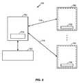
図8は、充電器704のブロック図を示す。図示するように、充電器704は、プロセッサ710およびメモリ712を含むことができる。1つの例示的実施形態によれば、メモリ712は、スケジューリングアプリケーション714を含むことができる。メモリ712は、データベース716を含むこともできる。1つの例示的実施形態において、スケジューリングアプリケーション714を実行する指示は、ジップドライブ、フロッピー(登録商標)ディスクドライブ、ハードドライブ、CD-ROMドライブ、テープドライブ、フラッシュメモリドライブなどの、1つまたは複数の固定もしくは着脱可能のデータ保存デバイスを含むことができる、コンピュータ読取可能媒体内で明白に具体化することができる。さらに、スケジューリングアプリケーション714は、プロセッサ710によって読まれ、かつ実行されるとき、本発明の実施形態を実施および/または使用するのに必要なステップをプロセッサ710に行わせることができる、指示を含むことができる。スケジューリングアプリケーション714および/または動作指示は、メモリ712および/またはデータ通信デバイス内で明白に具体化することもでき、それによって、本発明の実施形態によるコンピュータプログラム製品または製造品を作成する。したがって、本明細書に使用する用語「スケジューリングアプリケーション」は、いずれかのコンピュータ読取可能デバイスまたは媒体からアクセス可能なコンピュータプログラムを含むことを意図する。 FIG. 8 shows a block diagram of the
ここで、無線電力の送信のスケジューリングにおいて無線充電器704によって使用することができる充電属性を説明する。本発明の様々な例示的実施形態によれば、充電器704、より具体的には、スケジューリングアプリケーション714は、関連する充電領域内に位置する1つまたは複数の充電可能デバイスへの無線電力の送信のスケジューリングをするのにデータを利用するように構成することができる。より具体的には、以下により十分に説明するが、充電スケジュールを生成するために、スケジューリングアプリケーション714は、例えば、関連する充電領域内に位置する1つもしくは複数の充電可能デバイスに関する1つもしくは複数の属性、充電器704に関する1つもしくは複数の環境属性、1つもしくは複数の充電可能デバイスに関する1つもしくは複数の規定された優先順位属性、1人もしくは複数の充電可能デバイスユーザに関する1つもしくは複数の規定された優先順位属性、またはそれらのいずれかの組合せを使用するように構成することができる。より具体的には、1つの例として、スケジューリングアプリケーション714は、1つまたは複数の充電可能デバイスに関する1つまたは複数の静的属性を利用するように構成することができる。充電可能デバイスに関する静的属性は、例えば、単なる例として、充電可能デバイスのタイプ(例えば携帯電話)、充電可能デバイスのモデル(例えばモトローラ)、および充電可能デバイスのユーザを識別することができる。さらに、単なる例として、静的属性は、充電可能デバイスのバッテリのタイプ(例えばリチウムイオン)、充電可能デバイスのバッテリのモデル、充電可能デバイスのバッテリの充電容量、および充電可能デバイスのバッテリの充電速度関数を識別することができる。静的属性は、充電可能デバイスのバッテリの所望の充電継続時間、および充電可能デバイスのバッテリの連続的な充電時間の間の所望の時間ギャップを識別することもできる。 Here, charging attributes that can be used by the
バッテリの充電速度関数は、充電速度(すなわち、バッテリをどれだけ速く充電することができるか)とバッテリの充電状態(すなわち、バッテリ内に保存される充電量)との間の関係を表すことができることに留意されたい。当業者にはわかるように、バッテリの充電速度は、バッテリ内に保存された充電量が増加すると、減少する可能性がある。したがって、バッテリ内の充電量が最大レベルに近づくと、バッテリは、より低い充電速度を要求する可能性があり、したがって、バッテリに割り当てられる充電時間は、減少する可能性がある。さらに、バッテリの充電速度関数は、バッテリの年数、バッテリの温度、またはその両方に依存する可能性があることに留意されたい。 The battery charge rate function can represent the relationship between the charge rate (i.e. how fast the battery can be charged) and the state of charge of the battery (i.e. the amount of charge stored in the battery). Note that you can. As will be appreciated by those skilled in the art, the charging rate of a battery can decrease as the amount of charge stored in the battery increases. Thus, as the amount of charge in the battery approaches the maximum level, the battery may require a lower charge rate, and therefore the charge time allocated to the battery may decrease. In addition, it should be noted that the battery charge rate function may depend on the age of the battery, the temperature of the battery, or both.
それに加えて、別の例として、スケジューリングアプリケーション714は、充電スケジュールを生成し、実行するために、関連する充電領域内に位置する1つまたは複数の充電可能デバイスに関する1つまたは複数の動的属性を利用するように構成することができる。動的属性は、単なる例として、充電可能デバイスのバッテリの充電状態、充電可能デバイスのバッテリの温度、および充電可能デバイスのバッテリの年数を識別することができる。さらに、無線充電器704は、充電スケジュールを生成し、実行するときに、1つまたは複数の設定可能属性を利用するように適合することができる。設定可能属性は、単なる例として、1人または複数の既知の充電可能デバイスユーザ、1つまたは複数の既知の充電可能デバイスに関する規定された優先順位レベル、またはそれらのいずれかの組合せを識別することができる。単なる例として、携帯電話は、ポータブルメディアプレーヤに割り当てられる充電優先順位レベルよりも高い充電優先順位レベル割当てを有することができる。さらに、例えば、第1のユーザ(例えば大人)は、第2のユーザ(例えば子供)に割り当てられる充電優先順位レベルよりも高い充電優先順位レベル割当てを有することができる。 In addition, as another example, the
さらに、スケジューリングアプリケーション714は、関連する充電領域内に位置する1つまたは複数の充電可能デバイスへの無線電力の送信の充電スケジュールを生成し、実行するために、無線充電器704に関する1つまたは複数の環境属性を利用するように構成することができる。単なる例として、環境属性は、無線充電器704の充電領域内に位置する充電可能デバイスの数を識別することができる。別の例として、環境属性は、無線充電器704の充電領域内に位置する2つ以上の充電可能デバイス間の干渉パターンを識別することができる。2つ以上の充電可能デバイス間の干渉パターンは、充電可能デバイスのタイプ、充電可能デバイスに関するバッテリのタイプ、充電可能デバイスの相対位置および/もしくは方向、またはそれらのいずれかの組合せに依存する可能性があることに留意されたい。 Further, the
以下により十分に説明するように、充電スケジュールを決定するときに利用することができる属性(すなわち、静的属性、動的属性、設定可能属性、および環境属性)は、充電器704内に(すなわちデータベース716内に)保存することができ、1つもしくは複数の充電可能デバイスから無線充電器704に伝達することができ、遠隔データベースから検索することができ、他の受信属性(すなわち、1つもしくは複数の充電可能デバイスから伝達される属性および/またはネットワークから検索される属性)から無線充電器704によって引き出すことができるか、またはそれらのいずれかの組合せである。 As described more fully below, attributes that can be utilized when determining a charging schedule (i.e., static attributes, dynamic attributes, configurable attributes, and environmental attributes) are within charger 704 (i.e., Can be stored in the
図9は、無線充電器704、無線充電器704の充電領域内に位置する複数の充電可能デバイス702、および遠隔データベース720を含むシステム730を示す。様々な例示的実施形態によれば、ここで、無線充電器704の充電属性を得る方法を説明する。1つの例示的実施形態によれば、無線充電器704は、充電可能デバイス702の1つもしくは複数の特性、バッテリ708の1つもしくは複数の特性、またはそれらのいずれかの組合せに関する、充電可能デバイス702からのデータ(すなわち、1つまたは複数の属性)を無線で受信するように構成することができる。単なる例として、充電可能デバイス702は、無線充電器704の関連する充電領域内に位置した後、通信リンク718を介して、それに関する1つもしくは複数の静的特性、それに関する1つもしくは複数の動的特性、それに関する1つもしくは複数の設定可能属性、またはそれらのいずれかの組合せを、無線充電器704に無線で送信することができる。 FIG. 9 shows a
さらに、1つの例示的実施形態によれば、無線充電器704は、充電可能デバイス702の1つもしくは複数の特性、バッテリ708の1つもしくは複数の特性、またはそれらのいずれかの組合せに関するデータ(すなわち、1つまたは複数の属性)を検索するように構成することができる。例えば、無線充電器704は、充電可能デバイス702を検出すると、充電可能デバイス702からの関連する属性を検索するように構成することができる。別の例として、無線充電器704は、充電可能デバイス702が関連する充電領域内に位置すると、充電可能デバイス702のモデルタイプを識別する、充電可能デバイス702からの属性を受信するように構成することができる。さらに、無線充電器704は、モデルタイプを識別する属性を受信すると、充電可能デバイス702のモデルタイプに関する静的属性、遠隔データベース720、データベース716、またはそれらの組合せを検索するように構成することができる。上述のように、充電可能デバイスに関する静的属性は、例えば、充電可能デバイスのタイプ(例えば携帯電話)、または充電可能デバイスのユーザの同一性を識別することができる。さらに、無線充電器704は、遠隔データベース720、データベース716、充電可能デバイス702、またはそれらの組合せからバッテリ708に関する静的属性を検索するように構成することができる。上述のように、バッテリに関する静的属性は、バッテリのタイプ(例えばリチウムイオン)、バッテリのモデル、バッテリの充電容量、バッテリの充電速度関数、バッテリの所望の充電継続時間、バッテリの連続的な充電時間の間の所望の時間ギャップ、および温度に対するバッテリの充電速度関数を識別することができる。さらに、無線充電器704は、充電可能デバイス702に無線電力を供給する前、またはその間に、充電可能デバイス702からの、およびそれに関連する動的属性を検索するように構成することができる。さらに、無線充電器704は、遠隔データベース720、充電可能デバイス702、データベース716、またはそれらの組合せから充電可能デバイス702に関する設定可能属性を検索するように構成することができる。 Further, according to one exemplary embodiment,
別の例示的実施形態によれば、無線充電器704、より具体的には、データベース716は、充電可能デバイス702の1つもしくは複数の特性、バッテリ708の1つもしくは複数の特性、またはそれらのいずれかの組合せに関するデータ(すなわち属性)を保存するように構成することができる。単なる例として、データベース716は、充電可能デバイス702に関する静的属性、バッテリ708に関する静的属性、バッテリ708に関する動的属性、またはそれらのいずれかの組合せを保存するように構成することができる。さらに、データベース716は、単なる例として、1人もしくは複数の既知のユーザの規定された優先順位レベル、1つもしくは複数の既知の充電可能デバイスの規定された優先順位レベル、またはそれらのいずれかの組合せなどの設定可能属性を保存するように構成することができる。さらに、データベース716は、単なる例として、無線充電器704の充電領域内に位置する充電可能デバイスの数、または無線充電器704の充電領域内に位置する2つ以上の充電可能デバイス間の干渉パターンなどの環境属性に関するデータを保存するように構成することができる。 According to another exemplary embodiment,
さらに、別の例示的実施形態によれば、無線充電器704は、他の既知の属性に基づいて、充電可能デバイスタイプの1つもしくは複数の特性、バッテリタイプの1つもしくは複数の特性、またはそれらのいずれかの組合せに関するデータ(すなわち属性)を引き出すように構成することができる。単なる例として、無線充電器704は、バッテリのモデルを識別する属性を受信すると、単なる例としてバッテリ容量またはバッテリの充電速度関数などの、バッテリの1つまたは複数の静的属性を決定するように構成することができる。別の例として、無線充電器704は、バッテリの最初の充電状態、バッテリの充電速度、および充電時間の経過に基づいて、充電可能デバイスのバッテリの現在の充電状態を評価するように構成することができる。無線充電器704は、例えば、関連する充電領域内に位置する充電可能デバイスの数の検知、2つ以上の充電可能デバイス間の干渉パターンの検知、またはそれらのいずれかの組合せによって、1つまたは複数の環境属性を引き出すように構成することもできる。 Further, according to another exemplary embodiment, the
図9を参照すれば、ここで、無線充電器704における属性を得る方法の様々な企図される例を説明する。1つの例として、無線充電器704は、充電可能デバイス702を検出すると、充電可能デバイス702から利用可能な静的属性、動的属性、および設定可能属性を検索するように構成することができる。別の例として、充電可能デバイス702は、無線充電器704の充電領域内に位置すると、それからの変化を受信する前に、無線充電器704に1つまたは複数の静的属性を伝達することができる。さらに、無線電力を受信する前はいつでも、または無線電力を受信する間、それぞれの充電可能デバイス702は、1つまたは複数の動的属性を無線充電器704に伝達することができる。動的属性は、充電プロセス中に変化する可能性があり、したがって、それぞれの充電可能デバイス702は、定期的に、または充電プロセス中に必要に応じて、1つまたは複数の動的属性を無線充電器704に送信するように構成することができることに留意されたい。したがって、スケジューリングアプリケーション714は、充電プロセス中はいつでも、充電スケジュールを更新するように構成することができることに留意されたい。 Referring now to FIG. 9, various contemplated examples of methods for obtaining attributes in the
別の実施形態によれば、充電可能デバイス702は、無線充電器704の充電領域内に位置すると、それから充電を受ける前に、無線充電器704に主要な静的属性(例えば、バッテリ708のモデルを識別する属性)を伝達することができる。その後、主要な属性に基づいて、無線充電器704は、充電可能デバイス702に関し、かつデータベース716内に保存される1つまたは複数の他の静的属性を検索するように構成することができる。さらに別の例示的実施形態において、主要な属性に基づいて、無線充電器704は、遠隔データベース720から充電可能デバイス702に関する、1つまたは複数の他の静的属性を検索するように構成することができる。さらに、1つの例示的実施形態において、無線充電器704は、データベース716内の1つまたは複数の静的属性を検索することを試みるように構成することができ、1つまたは複数の静的属性の少なくとも1つの属性がデータベース716内に見つからないとき、無線充電器704は、遠隔データベース720から少なくとも1つの静的属性を検索することを試みることができる。 According to another embodiment, when the
それに加えて、充電可能デバイス702は、無線充電器704の充電領域内に位置した後、1つまたは複数の設定可能属性を無線充電器704に伝達することができる。例えば、充電可能デバイス702は、無線充電器704の充電領域内に位置した後、その優先順位レベルを無線充電器に伝達することができる。さらに、無線充電器704は、デバイスタイプ、デバイス同一性、またはユーザ同一性などの1つもしくは複数の他の属性に基づいて、1つもしくは複数の設定可能属性を局所的に引き出すか、または遠隔データベース720から1つもしくは複数の設定可能属性を検索することを試みるように構成することができる。 In addition, the
図10は、無線充電器704、および無線充電器704の充電領域707内に位置する複数の充電可能デバイス702A〜Dを示す。図10を参照すれば、ここで、無線充電器704から1つまたは複数の充電可能デバイス702A〜Dへの無線電力の送信のスケジューリングの様々な例示的実施形態を説明する。様々な例示的実施形態によれば、無線電力送信スケジュールは、1つまたは複数の充電可能デバイスを充電するのに時間区分を割り当てることができる、時間領域ベースのシーケンスに基づくことができる。それぞれの割当充電時間区分の間、無線充電器704は、電力を1つまたは複数の充電可能デバイスに無線で伝達することができることに留意されたい。さらに、充電可能デバイスが無線電力を受信するようにスケジューリングされていない時間区分中に「遮蔽」することができることに留意されたい。 FIG. 10 shows a
1つの例示的実施形態において、スケジューリングアプリケーション714(図8を参照)は、「総当り」方法で無線電力のそれぞれの充電可能デバイス702A〜Dへの送信をスケジューリングするように構成することができる。したがって、それぞれの充電可能デバイス702A〜Dは、等しい継続時間の間、電力を受信することができる。別の例示的実施形態において、スケジューリングアプリケーション714(図8を参照)は、充電可能デバイス702A〜Dを充電する順序を決定するように構成することができ、さらに、それぞれの充電可能デバイス702A〜Dの充電継続時間を決定することができる。より具体的には、スケジューリングアプリケーション714は、充電可能デバイス702A〜Dの1つもしくは複数に関する1つもしくは複数の静的属性、充電可能デバイス702A〜Dの1つもしくは複数に関する1つもしくは複数の動的属性、充電可能デバイス702A〜Dの1つもしくは複数に関する1つもしくは複数の設定可能属性、無線充電器704に関する1つもしくは複数の環境属性、またはそれらのいずれかの組合せに基づいて、充電可能デバイス702A〜Dを充電する順序、および/またはそれぞれの充電可能デバイス702A〜Dの充電継続時間を決定することができる。 In one exemplary embodiment, the scheduling application 714 (see FIG. 8) can be configured to schedule transmission of wireless power to each
より具体的には、例えば、スケジューリングアプリケーション714(図8を参照)は、それぞれの充電可能デバイスに割り当てられる重み係数によって、充電可能デバイス702A〜Dを充電する順序、および/またはそれぞれの充電可能デバイス702A〜Dの充電継続時間を決定するように構成することができる。単なる例として、充電可能デバイスに割り当てられる重み係数は、充電可能デバイスに関するデバイス優先順位、充電可能デバイスに関するユーザ優先順位、充電可能デバイスの充電速度、充電可能デバイスが最大充電量に達するのに要求される継続時間、またはそれらのいずれかの組合せに基づくことができる。 More specifically, for example, the scheduling application 714 (see FIG. 8) determines the order in which the
ここで、重み係数によって、充電可能デバイス702A〜Dを充電する順序、および/またはそれぞれの充電可能デバイス702A〜Dの充電継続時間を決定する企図された例を説明する。この例において、充電可能デバイス702Aは「高い」ユーザ優先順位を有し、充電可能デバイス702Bは「中間の」ユーザ優先順位を有し、充電可能デバイス702Cおよび充電可能デバイス702Dはそれぞれ「低い」ユーザ優先順位を有すると仮定する。したがって、合計充電継続時間Tの間、スケジューリングアプリケーション714は、第1にT/2の継続時間の間に無線電力を受信するように充電可能デバイス702Aをスケジューリングするように構成することができる。さらに、スケジューリングアプリケーション714は、第2にT/4の継続時間の間に無線電力を受信するように充電可能デバイス702Bをスケジューリングするように構成することができる。さらに、スケジューリングアプリケーション714は、T/8の継続時間の間に無線を受信するように充電可能デバイス702Cおよび充電可能デバイス702Dのそれぞれをスケジューリングするように構成することができる。この例において、無線電力を充電可能デバイス702Cおよび充電可能デバイス702Dのそれぞれに供給する順序は、充電可能デバイス702Cおよび充電可能デバイス702Dの1つもしくは複数の他の属性(例えば、充電速度もしくはデバイス優先順位)によって決定することができ、または無線電力は、ランダムな「総当り」方法で充電可能デバイス702Cおよび充電可能デバイス702Dのそれぞれに供給することができることに留意されたい。充電可能デバイスに割り当てられる重み係数は、充電可能デバイスに関する1つまたは複数の属性に依存する可能性があることに留意されたい。 A contemplated example will now be described in which the weighting factors determine the order in which the
別の例示的実施形態において、スケジューリングアプリケーション714は、それぞれの充電可能デバイス702A〜Dに割り当てられる優先順位レベルによって、充電可能デバイス702A〜Dを充電する順序を決定することができる。それぞれの充電可能デバイス702A〜Dに割り当てられる優先順位レベルは、デバイス優先順位(例えば、玩具より高いデバイス優先順位を有する携帯電話は、玩具よりも先に充電することができる)、ユーザ優先順位(例えば、子供の携帯電話よりも高いユーザ優先順位を有する大人の携帯電話は、子供の携帯電話よりも先に充電することができる)、充電効率(例えば、より高い充電効率を有する充電可能デバイスは、より低い充電効率を有する充電可能デバイスよりも先に充電される)、最大充電のための充電継続時間(例えば、最大充電量に達するのにより長い充電継続時間を必要とする充電可能デバイスは、最大充電量に達するのにより短い充電継続時間を必要とする充電可能デバイスよりも先に充電することができる)、充電レベル(例えば、20%充電されている充電可能デバイスは、80%充電されている充電可能デバイスよりも先に充電することができる)に依存する可能性がある。さらに、1つの例示的実施形態によれば、スケジューリングアプリケーション714は、より低い優先順位の充電可能デバイスに充電時間を割り当てる前に、より高い優先順位の充電可能デバイスにできるだけ多い充電時間を割り当てるように構成することができる。 In another exemplary embodiment,
ここで、それぞれの充電可能デバイス702A〜Dに割り当てられる優先順位レベルによって、充電可能デバイス702A〜Dを充電する順序を決定する企図された例を説明する。この例において、充電可能デバイス702Aは充電可能デバイス702Bよりも高いデバイス優先順位レベルを有し、充電可能デバイス702Bは充電可能デバイス702Cよりも高いデバイス優先順位レベルを有し、充電可能デバイス702Cは充電可能デバイス702Dよりも高いデバイス優先順位レベルを有すると仮定する。したがって、スケジューリングアプリケーション714は、第1の時間区分中に閾値充電量(完全充電)に達するのに必要な継続時間の間に充電可能デバイス702Aに無線電力を伝達し、第2の時間区分中に閾値充電量に達するのに必要な継続時間の間に充電可能デバイス702Bに無線電力を伝達し、第3の時間区分中に閾値充電量に達するのに必要な継続時間の間に充電可能デバイス702Cに無線電力を伝達し、第4の時間区分中に閾値充電量に達するのに必要な継続時間の間に充電可能デバイス702Dに無線電力を伝達するようにスケジューリングすることができる。 Now, a contemplated example will be described in which the order of charging the
ここで、それぞれの充電可能デバイス702A〜Dに割り当てられる優先順位レベルによって、充電可能デバイス702A〜Dを充電する順序を決定する企図された例を説明する。この例において、充電可能デバイス702Dは充電可能デバイス702Cよりも高い充電速度を有し、充電可能デバイス702Cは充電可能デバイス702Bよりも高い充電速度を有し、充電可能デバイス702Bは充電可能デバイス702Aよりも高い充電速度を有すると仮定する。したがって、スケジューリングアプリケーション714は、第1の時間区分中に充電可能デバイス702Dに無線電力を伝達し、第2の時間区分中に充電可能デバイス702Cに無線電力を伝達し、第3の時間区分中に充電可能デバイス702Bに無線電力を伝達し、第4の時間区分中に充電可能デバイス702Aに無線電力を伝達するようにスケジューリングすることができる。 Now, a contemplated example will be described in which the order of charging the
さらに、スケジューリングアプリケーション714は、複数の優先順位レベル指示(例えば、デバイス優先順位レベルおよび充電速度)、複数の重み係数指示、またはそれらのいずれかの組合せに基づいて、無線電力を供給するスケジュールを決定するように構成することができることに留意されたい。例えば、等しいユーザ優先順位レベルを有する2つの充電可能デバイス702に、充電速度に基づいて、ある順番に電力を供給することができる。別の例として、等しい優先順位レベルを有するバッテリを含む2つの充電可能デバイス702に、総当り方法または重み係数指示によって、電力を供給することができる。さらに、スケジューリングアプリケーション714は、無線充電器704の充電領域内に位置する2つ以上のデバイス間の干渉パターンなどの環境属性に基づいて、複数の充電可能デバイスへの無線電力の送信を同時にスケジューリングするように構成することができる。 Further, the
図11は、複数の充電可能デバイス802および無線充電器804を含むシステム800を示す。それぞれの充電可能デバイス802は、プロセッサ809、データベース806、送信機811、およびバッテリ808を含む。この図示された実施形態において、無線充電器804が、それぞれの充電可能デバイス802に関する属性を得ることを要求されない。むしろ、それぞれの充電可能デバイス802、より具体的には、プロセッサ809は、1つまたは複数の所望の関連する充電パラメータを決定するのに、充電可能デバイス802に関連し、かつ関連するデータベース806内に保存される属性を利用するように構成される。単なる例として、充電パラメータは、充電速度、充電継続時間、またはそれらの組合せを含むことができる。所望の充電パラメータは、充電可能デバイス802の充電プロセスを最適化するように選択することができることに留意されたい。充電可能デバイス802は、1つまたは複数の所望の関連する充電パラメータを決定すると、送信機811を介して通信リンク818によって無線充電器804に充電要求を送信することができる。例えば、充電要求は、所望の充電速度および最大充電速度を含むことができる。より具体的には、バッテリ808が最大充電量に近い例において、充電可能デバイス802は、通信リンク818によって、低頻度の短い一気の充電を要求する無線充電器804に信号を送信することができる。充電要求は、要求が有効である継続時間を含むこともできる。無線充電器804は、関連する充電領域内に位置するそれぞれの充電可能デバイス802から充電要求を受信すると、本明細書に説明する例示的実施形態の1つまたは複数によって、充電スケジュールを決定することができる。無線充電器804は、プロセッサ710およびスケジューリングアプリケーション714を含むことができることに留意されたい。さらに、充電可能デバイス802は、バッテリ808に関する最新情報(例えば属性)を得るために遠隔データベース820にアクセスするように構成することができることに留意されたい。 FIG. 11 shows a
図12は、1つまたは複数の例示的実施形態による方法680を示すフローチャートである。方法680は、無線充電器と、複数の充電可能デバイスの少なくとも1つの充電可能デバイスとの少なくとも1つに関する少なくとも1つの属性に基づいて、無線充電器の充電領域内に位置する複数の充電可能デバイスの1つまたは複数の充電可能デバイスへの無線電力の送信をスケジューリングするステップ(番号682によって示される)を含むことができる。 FIG. 12 is a flowchart illustrating a
本明細書に説明する様々な例示的実施形態の1つまたは複数による、無線電力の送信のスケジューリングは、無線電力送信効率の最大化、充電可能デバイスの優先順位付け、充電可能デバイスユーザの優先順位付け、ならびにバッテリ寿命保護および充電の公平性の増大を可能にすることができる。 Scheduling of wireless power transmission, in accordance with one or more of the various exemplary embodiments described herein, maximizes wireless power transmission efficiency, prioritizes rechargeable devices, priorities of rechargeable device users As well as battery life protection and increased charging fairness.
様々な異なる技術および技法のいずれかを使用して、情報および信号を表現することができることを当業者には理解されよう。例えば、以上の説明を通して言及することができるデータ、指示、命令、情報、信号、ビット、シンボル、およびチップは、電圧、電流、電磁波、磁場もしくは磁気粒子、光学場もしくは光学粒子、またはそれらのいずれかの組合せによって表現することができる。 Those of skill in the art will understand that information and signals may be represented using any of a variety of different technologies and techniques. For example, data, instructions, instructions, information, signals, bits, symbols, and chips that can be referred to throughout the above description are voltages, currents, electromagnetic waves, magnetic fields or magnetic particles, optical fields or optical particles, or any of them It can be expressed by the combination.
さらに、本明細書に開示した例示的実施形態に関連して説明した様々な例示的ロジックブロック、モジュール、回路、およびアルゴリズムステップを、電子ハードウェア、コンピュータソフトウェア、または両方の組合せとして実装することができることを当業者には理解されよう。ハードウェアおよびソフトウェアのこの互換性を明確に説明するために、様々な例示的構成要素、ブロック、モジュール、回路、およびステップを、それらの機能に関して以上に概略的に説明してきた。そうした機能がハードウェアまたはソフトウェアとして実装されるかどうかは、全体のシステムに課される特定の用途および設計の制約に依存する。当業者は、それぞれの特定の用途に対して様々な方法で、説明した機能を実装することができるが、そうした実装形態の決定は、本発明の例示的実施形態の範囲から逸脱するものと解釈されるべきでない。 Further, the various exemplary logic blocks, modules, circuits, and algorithm steps described in connection with the exemplary embodiments disclosed herein may be implemented as electronic hardware, computer software, or a combination of both. Those skilled in the art will understand that this is possible. To clearly illustrate this interchangeability of hardware and software, various illustrative components, blocks, modules, circuits, and steps have been described above generally in terms of their functionality. Whether such functionality is implemented as hardware or software depends upon the particular application and design constraints imposed on the overall system. Those skilled in the art can implement the described functionality in a variety of ways for each particular application, but such implementation decisions are interpreted as departing from the scope of the exemplary embodiments of the invention. Should not be done.
本明細書に開示した例示的実施形態に関連して説明した様々な例示的ロジックブロック、モジュール、および回路は、汎用プロセッサ、デジタル信号プロセッサ(DSP)、特定用途向け集積回路(ASIC)、フィールドプログラマブルゲートアレイ(FPGA)もしくは他のプログラマブルロジックデバイス、個々のゲートもしくはトランジスタロジック、個々のハードウェア構成要素、または本明細書に説明した機能を実行するために設計された、それらのいずれかの組合せによって実装または実行することができる。汎用プロセッサは、マイクロプロセッサとすることができるが、その代わりに、プロセッサは、いずれかの従来のプロセッサ、コントローラ、マイクロコントローラ、または状態マシンとすることができる。プロセッサは、DSPとマイクロプロセッサとの組合せ、複数のマイクロプロセッサ、DSPコアと協働する1つもしくは複数のマイクロプロセッサ、またはそうした他のいずれかの構成などのコンピュータデバイスの組合せとして実装することもできる。 The various exemplary logic blocks, modules, and circuits described in connection with the exemplary embodiments disclosed herein are general purpose processors, digital signal processors (DSPs), application specific integrated circuits (ASICs), field programmable. By a gate array (FPGA) or other programmable logic device, individual gate or transistor logic, individual hardware components, or any combination thereof designed to perform the functions described herein Can be implemented or implemented. A general purpose processor may be a microprocessor, but in the alternative, the processor may be any conventional processor, controller, microcontroller, or state machine. The processor may also be implemented as a combination of computing devices such as a combination of DSP and microprocessor, multiple microprocessors, one or more microprocessors cooperating with the DSP core, or any other such configuration. .
本明細書に開示した例示的実施形態に関連して説明した方法またはアルゴリズムのステップは、直接ハードウェアで、プロセッサによって実行されるソフトウェアモジュールで、またはその2つの組合せで具体化することができる。ソフトウェアモジュールは、ランダムアクセスメモリ(RAM)、フラッシュメモリ、リードオンリーメモリ(ROM)、電気的プログラマブルROM(EPROM)、電気的消去可能プログラマブルROM(EEPROM)、レジスタ、ハードディスク、リムーバブルディスク、CD-ROM、または当技術分野で知られている保存媒体の他のいずれかの形態内に存在することができる。例示的な保存媒体は、プロセッサが保存媒体から情報を読み、保存媒体に情報を書くことができるように、プロセッサに結合する。その代わりに、保存媒体は、プロセッサと一体化することができる。プロセッサおよび保存媒体は、ASIC内に存在することができる。ASICは、ユーザ端末内に存在することができる。その代わりに、プロセッサおよび保存媒体は、ユーザ端末内の個々の構成要素として存在することができる。 The method or algorithm steps described in connection with the exemplary embodiments disclosed herein may be implemented directly in hardware, in software modules executed by a processor, or in a combination of the two. Software modules include random access memory (RAM), flash memory, read only memory (ROM), electrically programmable ROM (EPROM), electrically erasable programmable ROM (EEPROM), register, hard disk, removable disk, CD-ROM, Or it can be present in any other form of storage medium known in the art. An exemplary storage medium is coupled to the processor such that the processor can read information from, and write information to, the storage medium. In the alternative, the storage medium may be integral to the processor. The processor and storage medium can reside in an ASIC. The ASIC can exist in the user terminal. In the alternative, the processor and the storage medium may reside as discrete components in a user terminal.
1つまたは複数の例示的実施形態において、説明した機能は、ハードウェア、ソフトウェア、ファームウェア、またはそれらのいずれかの組合せにおいて実装することができる。それらの機能は、ソフトウェア内に実装されるとき、コンピュータ読取可能媒体上の1つもしくは複数の指示またはコードとして保存され、または送信することができる。コンピュータ読取可能媒体は、コンピュータ保存媒体、およびある場所から別の場所へのコンピュータプログラムの送信を助けるいずれかの媒体を含む通信媒体のどちらも含む。保存媒体は、コンピュータによってアクセスすることができる、あらゆる利用可能な媒体とすることができる。例として、限定しないが、そうしたコンピュータ読取可能媒体は、RAM、ROM、EEPROM、CD-ROMもしくは他の光ディスクストレージ、磁気ディスクストレージもしくは他の磁気ストレージデバイス、または指示もしくはデータ構造の形態で所望のプログラムコードを保有もしくは保存するのに使用することができ、コンピュータによってアクセスすることができる他のいずれかの媒体を含むことができる。さらに、いずれかの接続部をコンピュータ読取可能媒体と呼ぶのがふさわしい。ソフトウェアが、ウェブサイト、サーバ、または同軸ケーブル、ファイバ光ケーブル、ツイストペア、デジタル加入者回線(DSL)、もしくは赤外線、無線、およびマイクロ波などの無線技術を使用する他の遠隔情報源から送信されるとき、同軸ケーブル、ファイバ光ケーブル、ツイストペア、DSL、または赤外線、無線、およびマイクロ波などの無線技術は、媒体の定義に含まれる。本明細書に使用されるディスク(diskおよびdisc)は、コンパクトディスク(CD)、レーザディスク、光ディスク、デジタル多用途ディスク(DVD)、フロッピー(登録商標)ディスク、およびブルーレイディスクを含み、ここで、diskは通常、磁気的にデータを再生するが、discは、レーザによってデータを光学的に再生する。以上のものの組合せも、コンピュータ読取可能媒体の範囲内に含むべきである。 In one or more exemplary embodiments, the functions described can be implemented in hardware, software, firmware, or any combination thereof. These functions, when implemented in software, can be stored or transmitted as one or more instructions or code on a computer-readable medium. Computer-readable media includes both computer storage media and communication media including any medium that facilitates transmission of a computer program from one place to another. A storage media can be any available media that can be accessed by a computer. By way of example, and not limitation, such computer readable media can be RAM, ROM, EEPROM, CD-ROM or other optical disk storage, magnetic disk storage or other magnetic storage device, or desired program in the form of instructions or data structures. Any other medium that can be used to hold or store the code and that can be accessed by a computer can be included. Furthermore, it is appropriate to call any connection part a computer readable medium. When the software is transmitted from a website, server, or other remote information source that uses coaxial technology, fiber optic cable, twisted pair, digital subscriber line (DSL), or wireless technologies such as infrared, wireless, and microwave Wireless technologies such as coaxial cable, fiber optic cable, twisted pair, DSL, or infrared, wireless, and microwave are included in the media definition. Discs (disks and discs) as used herein include compact discs (CDs), laser discs, optical discs, digital versatile discs (DVDs), floppy discs, and Blu-ray discs, where A disk normally reproduces data magnetically, whereas a disc optically reproduces data by a laser. Combinations of the above should also be included within the scope of computer-readable media.
開示した例示的実施形態の以上の説明は、当業者が本発明を作成または使用するのを可能にするために提供される。これらの例示的実施形態に対する様々な変更は、当業者には容易にわかり、本明細書に規定した一般的原理は、本発明の技術思想または範囲から逸脱することなく、他の実施形態に適用することができる。したがって、本発明は、本明細書に示した例示的実施形態に限定される意図はなく、本明細書に開示した原理および新規特徴と矛盾しない最も広い範囲とするべきである。 The previous description of the disclosed exemplary embodiments is provided to enable any person skilled in the art to make or use the present invention. Various modifications to these exemplary embodiments will be readily apparent to those skilled in the art, and the generic principles defined herein may be applied to other embodiments without departing from the spirit or scope of the invention. can do. Accordingly, the present invention is not intended to be limited to the exemplary embodiments shown herein, but is to be accorded the widest scope consistent with the principles and novel features disclosed herein.
100 無線電力送信システム
102 入力電力
104 送信機
106 放射場
108 受信機
110 出力電力
112 ある距離
114 送信アンテナ
118 受信アンテナ
119 通信チャネル
122 発信器
123 調整信号
124 パワーアンプ
125 制御信号
126 フィルタ付き整合回路
132 整合回路
134 整流器付きスイッチング回路
136 バッテリ
150 ループアンテナ
152 コンデンサ
154 コンデンサ
156 共振信号
200 送信機
202 送信回路
204 送信アンテナ
206 整合回路
208 ローパスフィルタ
210 パワーアンプ
212 発信器
214 コントローラ
216 負荷検知回路
220 搬送波信号
224 送信変調信号
226 入力電力
228 電力供給
230 差動アンプ
235 受信信号
260 エンクローズド検出器
270 メモリ
280 存在検出器
300 受信機
302 受信回路
304 受信アンテナ
306 電力変換回路
308 RF-DCコンバータ
310 DC-DCコンバータ
312 スイッチング回路
314 ビーコン検出器
316 プロセッサ
350 充電デバイス
680 方法
682 送信をスケジューリングするステップ
700 充電可能デバイスおよび無線充電器を含むシステム
702 充電可能デバイス
704 無線充電器
705 送信アンテナ
706 アンテナ
707 充電領域
708 バッテリ
710 プロセッサ
712 メモリ
714 スケジューリングアプリケーション
716 データベース
718 無線通信リンク
720 遠隔データベース
730 無線充電器、複数の充電可能デバイス、および遠隔データベースを含むシステム
800 無線充電器、複数の充電可能デバイス、および遠隔データベースを含むシステム
802 充電可能デバイス
804 無線充電器
806 データベース
808 バッテリ
809 プロセッサ
811 送信機
818 通信リンク
820 遠隔データベース100 wireless power transmission system
102 Input power
104 transmitter
106 Radiation field
108 Receiver
110 Output power
112 Distance
114 Transmit antenna
118 Receive antenna
119 communication channel
122 Transmitter
123 Adjustment signal
124 power amplifier
125 Control signal
126 Matching circuit with filter
132 Matching circuit
134 Switching circuit with rectifier
136 battery
150 loop antenna
152 capacitor
154 capacitors
156 Resonance signal
200 transmitter
202 Transmitter circuit
204 Transmit antenna
206 Matching circuit
208 Low-pass filter
210 Power amplifier
212 Transmitter
214 controller
216 Load detection circuit
220 Carrier signal
224 Transmit modulation signal
226 Input power
228 Power supply
230 Differential Amplifier
235 Received signal
260 Enclosed detector
270 memory
280 Presence detector
300 receiver
302 Receiver circuit
304 receiving antenna
306 Power conversion circuit
308 RF-DC converter
310 DC-DC converter
312 Switching circuit
314 Beacon detector
316 processor
350 charging device
680 methods
682 Steps to schedule transmission
700 system including rechargeable devices and wireless charger
702 Rechargeable device
704 wireless charger
705 Transmit antenna
706 Antenna
707 Charging area
708 battery
710 processor
712 memory
714 Scheduling application
716 database
718 wireless communication link
720 remote database
730 System including wireless charger, multiple rechargeable devices, and remote database
A system that includes an 800 wireless charger, multiple rechargeable devices, and a remote database
802 rechargeable device
804 wireless charger
806 database
808 battery
809 processor
811 transmitter
818 communication link
820 remote database
Claims (30)
Translated fromJapanese前記無線充電器と、関連する充電領域内に位置する複数の充電可能デバイスの少なくとも1つの充電可能デバイスとの少なくとも1つに関する少なくとも1つの属性に基づいて、充電スケジュールを決定するスケジューリングアプリケーションと、
前記充電スケジュールによって、前記複数の充電可能デバイスの1つまたは複数の充電可能デバイスに無線電力を伝達する送信機とを含む、無線充電器。A wireless charger,
A scheduling application that determines a charging schedule based on at least one attribute related to at least one of the wireless charger and at least one rechargeable device of a plurality of rechargeable devices located within an associated charging area;
A wireless charger comprising: a transmitter that transmits wireless power to one or more rechargeable devices of the plurality of rechargeable devices according to the charging schedule.
前記1つまたは複数の充電可能デバイスのそれぞれの充電可能デバイスに重み係数を割り当てるステップと、
それぞれの充電可能デバイスに割り当てられる前記重み係数によって、前記1つまたは複数の充電可能デバイスを充電する順序を決定するステップとをさらに含む、請求項12に記載の方法。Said scheduling step comprises:
Assigning a weighting factor to each rechargeable device of the one or more rechargeable devices;
13. The method of claim 12, further comprising: determining an order of charging the one or more chargeable devices according to the weighting factor assigned to each chargeable device.
前記1つまたは複数の充電可能デバイスのそれぞれの充電可能デバイスに優先順位レベルを割り当てるステップと、
それぞれの充電可能デバイスに割り当てられる前記優先順位レベルによって、前記1つまたは複数の充電可能デバイスを充電する順序を決定するステップとをさらに含む、請求項12に記載の方法。Said scheduling step comprises:
Assigning a priority level to each rechargeable device of the one or more rechargeable devices;
13. The method of claim 12, further comprising: determining an order of charging the one or more chargeable devices according to the priority level assigned to each chargeable device.
前記無線充電器と、前記無線充電器の充電領域内に位置する複数の充電可能デバイスの少なくとも1つの充電可能デバイスとの少なくとも1つに関する、1つまたは複数の属性を保存する手段と、
前記1つまたは複数の属性の少なくとも1つの属性に基づいて、前記複数の充電可能デバイスの1つまたは複数の充電可能デバイスへの無線電力の送信をスケジューリングする手段とを含む、無線充電器。A wireless charger,
Means for storing one or more attributes relating to at least one of the wireless charger and at least one rechargeable device of a plurality of rechargeable devices located within a charging area of the wireless charger;
Means for scheduling the transmission of wireless power to one or more rechargeable devices of the plurality of rechargeable devices based on at least one attribute of the one or more attributes.
前記1つまたは複数の所望の充電パラメータによって充電を要求する、前記充電可能デバイスから無線充電器への充電要求を送信するステップとを含む、方法。Determining one or more desired charging parameters of the rechargeable device according to one or more attributes relating to the rechargeable device;
Transmitting a request for charging from the rechargeable device to a wireless charger that requests charging according to the one or more desired charging parameters.
前記1つまたは複数の所望の充電パラメータによって充電を要求する、無線充電器への充電要求を送信する送信機とを含む、充電可能デバイス。A processor that determines one or more desired charging parameters according to one or more attributes relating to the rechargeable device;
And a transmitter that transmits a charge request to a wireless charger that requests charging according to the one or more desired charging parameters.
Applications Claiming Priority (5)
| Application Number | Priority Date | Filing Date | Title |
|---|---|---|---|
| US16751209P | 2009-04-07 | 2009-04-07 | |
| US61/167,512 | 2009-04-07 | ||
| US12/715,988 | 2010-03-02 | ||
| US12/715,988US8970180B2 (en) | 2009-04-07 | 2010-03-02 | Wireless power transmission scheduling |
| PCT/US2010/030278WO2010118161A2 (en) | 2009-04-07 | 2010-04-07 | Wireless power transmission scheduling |
Publications (2)
| Publication Number | Publication Date |
|---|---|
| JP2012523813Atrue JP2012523813A (en) | 2012-10-04 |
| JP5681167B2 JP5681167B2 (en) | 2015-03-04 |
Family
ID=42825634
Family Applications (1)
| Application Number | Title | Priority Date | Filing Date |
|---|---|---|---|
| JP2012504834AExpired - Fee RelatedJP5681167B2 (en) | 2009-04-07 | 2010-04-07 | Wireless power transmission scheduling |
Country Status (7)
| Country | Link |
|---|---|
| US (1) | US8970180B2 (en) |
| EP (1) | EP2417806B1 (en) |
| JP (1) | JP5681167B2 (en) |
| KR (1) | KR101749355B1 (en) |
| CN (1) | CN102440037B (en) |
| TW (1) | TW201108550A (en) |
| WO (1) | WO2010118161A2 (en) |
Cited By (8)
| Publication number | Priority date | Publication date | Assignee | Title |
|---|---|---|---|---|
| WO2015199938A1 (en)* | 2014-06-27 | 2015-12-30 | Intel Corporation | Systems and methods for smart wireless charging |
| KR20160007332A (en)* | 2014-07-11 | 2016-01-20 | 삼성전기주식회사 | Wireless power transmitter and wireless power transmitting system |
| KR20160012020A (en)* | 2014-07-23 | 2016-02-02 | 삼성전자주식회사 | Wireless power transfer system and method based on transfer schedule |
| JP2017188995A (en)* | 2016-04-04 | 2017-10-12 | 清水建設株式会社 | Wireless power supply system |
| US20180301925A1 (en) | 2016-12-08 | 2018-10-18 | Huawei Technologies Co., Ltd. | Intelligent Wireless Charging Control Method, Device, and System |
| JP2018198511A (en)* | 2017-05-24 | 2018-12-13 | キヤノン株式会社 | Power feeding device, control method thereof and program |
| JP2021191120A (en)* | 2020-05-29 | 2021-12-13 | ソフトバンク株式会社 | Information processing equipment, information processing programs and information processing systems |
| JP2023534829A (en)* | 2020-07-20 | 2023-08-14 | ゼネラル・エレクトリック・カンパニイ | Wireless charging for time slices |
Families Citing this family (284)
| Publication number | Priority date | Publication date | Assignee | Title |
|---|---|---|---|---|
| US7825543B2 (en) | 2005-07-12 | 2010-11-02 | Massachusetts Institute Of Technology | Wireless energy transfer |
| US11201500B2 (en) | 2006-01-31 | 2021-12-14 | Mojo Mobility, Inc. | Efficiencies and flexibilities in inductive (wireless) charging |
| US8169185B2 (en) | 2006-01-31 | 2012-05-01 | Mojo Mobility, Inc. | System and method for inductive charging of portable devices |
| US7952322B2 (en) | 2006-01-31 | 2011-05-31 | Mojo Mobility, Inc. | Inductive power source and charging system |
| US11329511B2 (en) | 2006-06-01 | 2022-05-10 | Mojo Mobility Inc. | Power source, charging system, and inductive receiver for mobile devices |
| US7948208B2 (en) | 2006-06-01 | 2011-05-24 | Mojo Mobility, Inc. | Power source, charging system, and inductive receiver for mobile devices |
| US9421388B2 (en) | 2007-06-01 | 2016-08-23 | Witricity Corporation | Power generation for implantable devices |
| US8115448B2 (en) | 2007-06-01 | 2012-02-14 | Michael Sasha John | Systems and methods for wireless power |
| US20110050164A1 (en) | 2008-05-07 | 2011-03-03 | Afshin Partovi | System and methods for inductive charging, and improvements and uses thereof |
| CN102099958B (en) | 2008-05-14 | 2013-12-25 | 麻省理工学院 | Wireless power transfer including interference enhancement |
| US9473209B2 (en)* | 2008-08-20 | 2016-10-18 | Intel Corporation | Wireless power transfer apparatus and method thereof |
| US8946938B2 (en) | 2008-09-27 | 2015-02-03 | Witricity Corporation | Safety systems for wireless energy transfer in vehicle applications |
| US9035499B2 (en) | 2008-09-27 | 2015-05-19 | Witricity Corporation | Wireless energy transfer for photovoltaic panels |
| US8461720B2 (en) | 2008-09-27 | 2013-06-11 | Witricity Corporation | Wireless energy transfer using conducting surfaces to shape fields and reduce loss |
| US9106203B2 (en) | 2008-09-27 | 2015-08-11 | Witricity Corporation | Secure wireless energy transfer in medical applications |
| US8692410B2 (en) | 2008-09-27 | 2014-04-08 | Witricity Corporation | Wireless energy transfer with frequency hopping |
| US9544683B2 (en) | 2008-09-27 | 2017-01-10 | Witricity Corporation | Wirelessly powered audio devices |
| US8598743B2 (en) | 2008-09-27 | 2013-12-03 | Witricity Corporation | Resonator arrays for wireless energy transfer |
| US8471410B2 (en) | 2008-09-27 | 2013-06-25 | Witricity Corporation | Wireless energy transfer over distance using field shaping to improve the coupling factor |
| US9601261B2 (en) | 2008-09-27 | 2017-03-21 | Witricity Corporation | Wireless energy transfer using repeater resonators |
| US8487480B1 (en) | 2008-09-27 | 2013-07-16 | Witricity Corporation | Wireless energy transfer resonator kit |
| US8901779B2 (en) | 2008-09-27 | 2014-12-02 | Witricity Corporation | Wireless energy transfer with resonator arrays for medical applications |
| US9184595B2 (en) | 2008-09-27 | 2015-11-10 | Witricity Corporation | Wireless energy transfer in lossy environments |
| US8686598B2 (en) | 2008-09-27 | 2014-04-01 | Witricity Corporation | Wireless energy transfer for supplying power and heat to a device |
| US8922066B2 (en) | 2008-09-27 | 2014-12-30 | Witricity Corporation | Wireless energy transfer with multi resonator arrays for vehicle applications |
| US9160203B2 (en) | 2008-09-27 | 2015-10-13 | Witricity Corporation | Wireless powered television |
| US8400017B2 (en) | 2008-09-27 | 2013-03-19 | Witricity Corporation | Wireless energy transfer for computer peripheral applications |
| US8569914B2 (en) | 2008-09-27 | 2013-10-29 | Witricity Corporation | Wireless energy transfer using object positioning for improved k |
| US8957549B2 (en) | 2008-09-27 | 2015-02-17 | Witricity Corporation | Tunable wireless energy transfer for in-vehicle applications |
| US8928276B2 (en) | 2008-09-27 | 2015-01-06 | Witricity Corporation | Integrated repeaters for cell phone applications |
| US9744858B2 (en) | 2008-09-27 | 2017-08-29 | Witricity Corporation | System for wireless energy distribution in a vehicle |
| US8907531B2 (en) | 2008-09-27 | 2014-12-09 | Witricity Corporation | Wireless energy transfer with variable size resonators for medical applications |
| US9246336B2 (en) | 2008-09-27 | 2016-01-26 | Witricity Corporation | Resonator optimizations for wireless energy transfer |
| US8497601B2 (en) | 2008-09-27 | 2013-07-30 | Witricity Corporation | Wireless energy transfer converters |
| US8552592B2 (en) | 2008-09-27 | 2013-10-08 | Witricity Corporation | Wireless energy transfer with feedback control for lighting applications |
| US8410636B2 (en) | 2008-09-27 | 2013-04-02 | Witricity Corporation | Low AC resistance conductor designs |
| US9105959B2 (en) | 2008-09-27 | 2015-08-11 | Witricity Corporation | Resonator enclosure |
| US8947186B2 (en) | 2008-09-27 | 2015-02-03 | Witricity Corporation | Wireless energy transfer resonator thermal management |
| US8643326B2 (en) | 2008-09-27 | 2014-02-04 | Witricity Corporation | Tunable wireless energy transfer systems |
| US8912687B2 (en) | 2008-09-27 | 2014-12-16 | Witricity Corporation | Secure wireless energy transfer for vehicle applications |
| US8466583B2 (en) | 2008-09-27 | 2013-06-18 | Witricity Corporation | Tunable wireless energy transfer for outdoor lighting applications |
| US8933594B2 (en) | 2008-09-27 | 2015-01-13 | Witricity Corporation | Wireless energy transfer for vehicles |
| US9093853B2 (en) | 2008-09-27 | 2015-07-28 | Witricity Corporation | Flexible resonator attachment |
| US8901778B2 (en) | 2008-09-27 | 2014-12-02 | Witricity Corporation | Wireless energy transfer with variable size resonators for implanted medical devices |
| US9577436B2 (en) | 2008-09-27 | 2017-02-21 | Witricity Corporation | Wireless energy transfer for implantable devices |
| US8669676B2 (en) | 2008-09-27 | 2014-03-11 | Witricity Corporation | Wireless energy transfer across variable distances using field shaping with magnetic materials to improve the coupling factor |
| US8723366B2 (en) | 2008-09-27 | 2014-05-13 | Witricity Corporation | Wireless energy transfer resonator enclosures |
| US8772973B2 (en) | 2008-09-27 | 2014-07-08 | Witricity Corporation | Integrated resonator-shield structures |
| US9318922B2 (en) | 2008-09-27 | 2016-04-19 | Witricity Corporation | Mechanically removable wireless power vehicle seat assembly |
| US8587153B2 (en) | 2008-09-27 | 2013-11-19 | Witricity Corporation | Wireless energy transfer using high Q resonators for lighting applications |
| US8324759B2 (en) | 2008-09-27 | 2012-12-04 | Witricity Corporation | Wireless energy transfer using magnetic materials to shape field and reduce loss |
| US9065423B2 (en) | 2008-09-27 | 2015-06-23 | Witricity Corporation | Wireless energy distribution system |
| US8587155B2 (en) | 2008-09-27 | 2013-11-19 | Witricity Corporation | Wireless energy transfer using repeater resonators |
| US9396867B2 (en) | 2008-09-27 | 2016-07-19 | Witricity Corporation | Integrated resonator-shield structures |
| US9601266B2 (en) | 2008-09-27 | 2017-03-21 | Witricity Corporation | Multiple connected resonators with a single electronic circuit |
| US8441154B2 (en) | 2008-09-27 | 2013-05-14 | Witricity Corporation | Multi-resonator wireless energy transfer for exterior lighting |
| US8937408B2 (en) | 2008-09-27 | 2015-01-20 | Witricity Corporation | Wireless energy transfer for medical applications |
| US8963488B2 (en) | 2008-09-27 | 2015-02-24 | Witricity Corporation | Position insensitive wireless charging |
| US8304935B2 (en) | 2008-09-27 | 2012-11-06 | Witricity Corporation | Wireless energy transfer using field shaping to reduce loss |
| US9601270B2 (en) | 2008-09-27 | 2017-03-21 | Witricity Corporation | Low AC resistance conductor designs |
| US8476788B2 (en) | 2008-09-27 | 2013-07-02 | Witricity Corporation | Wireless energy transfer with high-Q resonators using field shaping to improve K |
| US8629578B2 (en) | 2008-09-27 | 2014-01-14 | Witricity Corporation | Wireless energy transfer systems |
| US8482158B2 (en) | 2008-09-27 | 2013-07-09 | Witricity Corporation | Wireless energy transfer using variable size resonators and system monitoring |
| EP3179640A1 (en) | 2008-09-27 | 2017-06-14 | WiTricity Corporation | Wireless energy transfer systems |
| US8461722B2 (en) | 2008-09-27 | 2013-06-11 | Witricity Corporation | Wireless energy transfer using conducting surfaces to shape field and improve K |
| US8461721B2 (en) | 2008-09-27 | 2013-06-11 | Witricity Corporation | Wireless energy transfer using object positioning for low loss |
| US8692412B2 (en) | 2008-09-27 | 2014-04-08 | Witricity Corporation | Temperature compensation in a wireless transfer system |
| US9515494B2 (en) | 2008-09-27 | 2016-12-06 | Witricity Corporation | Wireless power system including impedance matching network |
| US8362651B2 (en) | 2008-10-01 | 2013-01-29 | Massachusetts Institute Of Technology | Efficient near-field wireless energy transfer using adiabatic system variations |
| CN102160252B (en)* | 2009-02-25 | 2015-04-29 | 上海贝尔股份有限公司 | Method and apparatus for increasing the number of powered devices supported by power over Ethernet system |
| US8853995B2 (en)* | 2009-06-12 | 2014-10-07 | Qualcomm Incorporated | Devices for conveying wireless power and methods of operation thereof |
| JP5499534B2 (en)* | 2009-07-07 | 2014-05-21 | ソニー株式会社 | Non-contact power receiving apparatus, power receiving method in non-contact power receiving apparatus, and non-contact power feeding system |
| US8547057B2 (en)* | 2009-11-17 | 2013-10-01 | Qualcomm Incorporated | Systems and methods for selective wireless power transfer |
| US10210216B2 (en)* | 2009-12-18 | 2019-02-19 | Sybase, Inc. | Dynamic attributes for mobile business objects |
| US9153995B2 (en)* | 2010-01-26 | 2015-10-06 | Broadcom Corporation | Smart power delivery system and related method |
| WO2011156768A2 (en) | 2010-06-11 | 2011-12-15 | Mojo Mobility, Inc. | System for wireless power transfer that supports interoperability, and multi-pole magnets for use therewith |
| US9438063B2 (en) | 2010-07-09 | 2016-09-06 | Industrial Technology Research Institute | Charge apparatus |
| US10211664B2 (en) | 2010-07-09 | 2019-02-19 | Industrial Technology Research Institute | Apparatus for transmission of wireless energy |
| US8692505B2 (en)* | 2010-07-09 | 2014-04-08 | Industrial Technology Research Institute | Charge apparatus |
| US9602168B2 (en) | 2010-08-31 | 2017-03-21 | Witricity Corporation | Communication in wireless energy transfer systems |
| CA2815218C (en) | 2010-10-22 | 2018-10-09 | Nucleus Scientific, Inc. | Apparatus and method for rapidly charging batteries |
| US20120104997A1 (en)* | 2010-11-01 | 2012-05-03 | Qualcomm Incorporated | Wireless charging device |
| KR101735558B1 (en)* | 2010-11-10 | 2017-05-16 | 삼성전자주식회사 | Resonance Power Transmission System and Method to Control Resonance Power Transmitting and Receiving |
| AU2011332142B2 (en)* | 2010-11-23 | 2014-12-11 | Apple Inc. | Wireless power utilization in a local computing environment |
| EP2654177A4 (en) | 2010-12-16 | 2014-06-25 | Lg Electronics Inc | Wireless power supply device, electronic device capable of receiving wireless power, and method for controlling transmission of wireless power |
| KR101813029B1 (en)* | 2010-12-17 | 2017-12-28 | 엘지전자 주식회사 | Wireless power transmission method, wireless power receiving method, wireless power transmission apparatus and wireless power receiving apparatus |
| US9178369B2 (en) | 2011-01-18 | 2015-11-03 | Mojo Mobility, Inc. | Systems and methods for providing positioning freedom, and support of different voltages, protocols, and power levels in a wireless power system |
| US10115520B2 (en) | 2011-01-18 | 2018-10-30 | Mojo Mobility, Inc. | Systems and method for wireless power transfer |
| US9496732B2 (en) | 2011-01-18 | 2016-11-15 | Mojo Mobility, Inc. | Systems and methods for wireless power transfer |
| US11342777B2 (en) | 2011-01-18 | 2022-05-24 | Mojo Mobility, Inc. | Powering and/or charging with more than one protocol |
| KR101779344B1 (en)* | 2011-02-07 | 2017-09-19 | 삼성전자주식회사 | Method and Apparatus for controlling wireless power transmission and reception, and wireless power transmission system |
| KR101778163B1 (en)* | 2011-03-04 | 2017-09-13 | 엘지전자 주식회사 | Wireless charging for 2-d goggles using an image display device |
| KR101785456B1 (en) | 2011-04-25 | 2017-11-06 | 엘지전자 주식회사 | Apparatus and system for providing wireless power charge service |
| US9035601B2 (en)* | 2011-05-05 | 2015-05-19 | Samsung Electro-Mechanics | Wireless power transfer system and methods |
| US8980174B2 (en)* | 2011-05-13 | 2015-03-17 | Bactriblue, Ltd. | Methods and apparatus for reducing count of infectious agents in intravenous access system |
| EP2712051B1 (en)* | 2011-05-13 | 2017-11-01 | Samsung Electronics Co., Ltd. | Transmitter and receiver in a wireless power transmitting system, and method for the transmitter and receiver to wirelessly transmit/receivetransceive power |
| US9244500B2 (en)* | 2011-05-23 | 2016-01-26 | Intel Corporation | System integration supporting completely wireless peripheral applications |
| US9391461B2 (en)* | 2011-05-31 | 2016-07-12 | Samsung Electronics Co., Ltd. | Wireless power transmission and charging system, and power control method of wireless power transmission and charging system |
| KR101948089B1 (en)* | 2011-06-01 | 2019-02-15 | 삼성전자주식회사 | Method and apparatus for detecting load fluctuation of wireless power transmission |
| KR101968601B1 (en)* | 2011-06-01 | 2019-04-15 | 삼성전자주식회사 | Method and apparatus for control of wireless power transmission |
| KR101832331B1 (en)* | 2011-06-29 | 2018-02-26 | 엘지전자 주식회사 | Wireless power transmission and communication between devices |
| US9948145B2 (en) | 2011-07-08 | 2018-04-17 | Witricity Corporation | Wireless power transfer for a seat-vest-helmet system |
| CN108110907B (en) | 2011-08-04 | 2022-08-02 | 韦特里西提公司 | Tunable wireless power supply architecture |
| US20130058379A1 (en)* | 2011-09-05 | 2013-03-07 | Samsung Electronics Co., Ltd. | Communication apparatus and communication method in wireless power transmission system |
| JP5786944B2 (en)* | 2011-09-08 | 2015-09-30 | 富士通株式会社 | Power transmission device, power reception device, and contactless charging method |
| WO2013035188A1 (en)* | 2011-09-08 | 2013-03-14 | 富士通株式会社 | Transmitting device, receiving device, and non-contact charging method |
| IN2014CN02466A (en) | 2011-09-08 | 2015-06-19 | Samsung Electronics Co Ltd | |
| EP2754222B1 (en) | 2011-09-09 | 2015-11-18 | Witricity Corporation | Foreign object detection in wireless energy transfer systems |
| US20130062966A1 (en) | 2011-09-12 | 2013-03-14 | Witricity Corporation | Reconfigurable control architectures and algorithms for electric vehicle wireless energy transfer systems |
| KR101781650B1 (en) | 2011-10-04 | 2017-09-26 | 삼성전자주식회사 | Wireless power multi-charge method and power transmitter |
| KR101317360B1 (en) | 2011-10-04 | 2013-10-11 | 주식회사 한림포스텍 | Wireless power transmitter and method |
| US9318257B2 (en) | 2011-10-18 | 2016-04-19 | Witricity Corporation | Wireless energy transfer for packaging |
| KR101979261B1 (en)* | 2011-10-24 | 2019-08-28 | 삼성전자주식회사 | Wireless power transmitter and method for controlling thereof |
| CA2853824A1 (en) | 2011-11-04 | 2013-05-10 | Witricity Corporation | Wireless energy transfer modeling tool |
| KR101338732B1 (en) | 2011-11-10 | 2013-12-06 | 엘지이노텍 주식회사 | Apparatus for transmmiting wireless power and apparatus for receiving wireless power and method for transmitting wireless power, method for receiving wireless power, method for transmitting information and method for receiving information |
| US9118203B2 (en) | 2011-11-15 | 2015-08-25 | Qualcomm Incorporated | Systems and methods for induction charging with a closed magnetic loop |
| WO2013105920A2 (en)* | 2011-12-09 | 2013-07-18 | Intel Corporation | Implementing wireless power transfer with 60 ghz mmwave communication |
| KR101848931B1 (en)* | 2011-12-15 | 2018-04-16 | 삼성전자주식회사 | Wireless power charge device and method |
| KR101951358B1 (en) | 2011-12-15 | 2019-02-22 | 삼성전자주식회사 | Wireless power transmitter, wireless power receiver and method for controlling each thereof |
| US9806537B2 (en) | 2011-12-15 | 2017-10-31 | Samsung Electronics Co., Ltd | Apparatus and method for determining whether a power receiver is removed from the apparatus |
| TWI669895B (en)* | 2011-12-16 | 2019-08-21 | 日商半導體能源研究所股份有限公司 | Portable information terminal |
| KR101889868B1 (en) | 2012-01-10 | 2018-08-20 | 삼성전자주식회사 | Apparatus and method for wireless energy transmission based on frame |
| US9748790B2 (en)* | 2012-01-12 | 2017-08-29 | Facebook, Inc. | System and method for a variable impedance transmitter path for charging wireless devices |
| JP2015508987A (en) | 2012-01-26 | 2015-03-23 | ワイトリシティ コーポレーションWitricity Corporation | Wireless energy transmission with reduced field |
| US8933589B2 (en) | 2012-02-07 | 2015-01-13 | The Gillette Company | Wireless power transfer using separately tunable resonators |
| US9018898B2 (en)* | 2012-02-10 | 2015-04-28 | Sandisk Technologies Inc. | Regulation of wirelessly charging multiple devices from the same source |
| KR101902795B1 (en)* | 2012-02-21 | 2018-11-14 | 삼성전자주식회사 | Method for wireless charging and apparatus for the same |
| KR20130098521A (en)* | 2012-02-28 | 2013-09-05 | 삼성전자주식회사 | Wireless power providing device and method for controlling thereof |
| US20130271069A1 (en) | 2012-03-21 | 2013-10-17 | Mojo Mobility, Inc. | Systems and methods for wireless power transfer |
| US9722447B2 (en) | 2012-03-21 | 2017-08-01 | Mojo Mobility, Inc. | System and method for charging or powering devices, such as robots, electric vehicles, or other mobile devices or equipment |
| KR101924341B1 (en) | 2012-04-09 | 2018-12-03 | 삼성전자주식회사 | Apparatus and method for controlling wireless power transmission |
| WO2013157681A1 (en)* | 2012-04-20 | 2013-10-24 | 전자부품연구원 | Wireless multi-charging method and wireless multi-charging system |
| US9558883B2 (en)* | 2012-05-02 | 2017-01-31 | Samsung Electronics Co., Ltd | Power transmitter and method for controlling power transmission |
| US20130304583A1 (en)* | 2012-05-14 | 2013-11-14 | Lg Electronics Inc. | Mobile terminal and control method thereof |
| US9218031B2 (en) | 2012-05-18 | 2015-12-22 | Dell Products, Lp | System and method for providing wireless power feedback in a wireless power delivery system |
| KR101920236B1 (en) | 2012-06-19 | 2018-11-20 | 삼성전자주식회사 | Method for charging battery and an electronic device thereof |
| US9343922B2 (en) | 2012-06-27 | 2016-05-17 | Witricity Corporation | Wireless energy transfer for rechargeable batteries |
| US10965164B2 (en) | 2012-07-06 | 2021-03-30 | Energous Corporation | Systems and methods of wirelessly delivering power to a receiver device |
| US12057715B2 (en) | 2012-07-06 | 2024-08-06 | Energous Corporation | Systems and methods of wirelessly delivering power to a wireless-power receiver device in response to a change of orientation of the wireless-power receiver device |
| US10312715B2 (en) | 2015-09-16 | 2019-06-04 | Energous Corporation | Systems and methods for wireless power charging |
| US9825674B1 (en) | 2014-05-23 | 2017-11-21 | Energous Corporation | Enhanced transmitter that selects configurations of antenna elements for performing wireless power transmission and receiving functions |
| US10090886B1 (en)* | 2014-07-14 | 2018-10-02 | Energous Corporation | System and method for enabling automatic charging schedules in a wireless power network to one or more devices |
| US11502551B2 (en) | 2012-07-06 | 2022-11-15 | Energous Corporation | Wirelessly charging multiple wireless-power receivers using different subsets of an antenna array to focus energy at different locations |
| US10992187B2 (en) | 2012-07-06 | 2021-04-27 | Energous Corporation | System and methods of using electromagnetic waves to wirelessly deliver power to electronic devices |
| US10992185B2 (en) | 2012-07-06 | 2021-04-27 | Energous Corporation | Systems and methods of using electromagnetic waves to wirelessly deliver power to game controllers |
| US9722670B2 (en)* | 2012-07-31 | 2017-08-01 | Intellectual Discovery Co., Ltd. | Wireless power transmission network and wireless power transmission method |
| US9287607B2 (en) | 2012-07-31 | 2016-03-15 | Witricity Corporation | Resonator fine tuning |
| KR101425603B1 (en)* | 2012-07-31 | 2014-08-04 | 인텔렉추얼디스커버리 주식회사 | Charging method of multi-node wireless charging system capable of charging plural devices simultaneoulsy |
| KR101455170B1 (en)* | 2012-07-31 | 2014-10-28 | 인텔렉추얼디스커버리 주식회사 | Charging method of multi-node wireless charging system based on wireless communication |
| WO2014021619A2 (en)* | 2012-07-31 | 2014-02-06 | 인텔렉추얼 디스커버리 주식회사 | Method for wirelessly charging multi-node wireless power transmitting system |
| KR102058367B1 (en)* | 2012-08-20 | 2019-12-24 | 엘지전자 주식회사 | Wireless power transmitter having the function of adjusting wireless power transmittion gain and the method of wireless power transmittion |
| US10173539B2 (en)* | 2012-08-31 | 2019-01-08 | Siemens Aktiengesellschaft | Battery charging system and method for cableless charging of a battery with voltage and current sensors on both the primary and secondary sides and a DC-DC converter on the primary side involved in an efficiency calibration power loop |
| WO2014038265A1 (en) | 2012-09-05 | 2014-03-13 | ルネサスエレクトロニクス株式会社 | Non-contact charging device, and non-contact power supply system using same |
| KR101985820B1 (en)* | 2012-09-07 | 2019-06-04 | 삼성전자주식회사 | Method and apparatus for transmitting and receiving wireless power |
| WO2014040233A1 (en)* | 2012-09-11 | 2014-03-20 | 东莞宇龙通信科技有限公司 | Wireless charger and multi-terminal wireless charging method |
| US9595378B2 (en) | 2012-09-19 | 2017-03-14 | Witricity Corporation | Resonator enclosure |
| US9455596B2 (en) | 2012-10-16 | 2016-09-27 | Ford Global Technologies, Llc | System and method for reducing interference between wireless charging and amplitude modulation reception |
| US9124124B2 (en) | 2012-10-16 | 2015-09-01 | Ford Global Technologies, Llc | System and method for reducing interference during wireless charging |
| EP2909912B1 (en) | 2012-10-19 | 2022-08-10 | WiTricity Corporation | Foreign object detection in wireless energy transfer systems |
| US9065157B2 (en)* | 2012-11-08 | 2015-06-23 | Ford Global Technologies, Llc | System and method for reducing thermal conditions during wireless charging |
| CN104885333B (en) | 2012-11-09 | 2018-05-15 | 加州理工学院 | Smart RF Lensing: Efficient, Dynamic, and Mobile Wireless Power Transfer |
| US11843260B2 (en) | 2012-11-09 | 2023-12-12 | California Institute Of Technology | Generator unit for wireless power transfer |
| US11616520B2 (en) | 2012-11-09 | 2023-03-28 | California Institute Of Technology | RF receiver |
| US9842684B2 (en) | 2012-11-16 | 2017-12-12 | Witricity Corporation | Systems and methods for wireless power system with improved performance and/or ease of use |
| KR101455693B1 (en)* | 2012-11-26 | 2014-11-03 | 한국전기연구원 | Wireless power transmission systems that support multiple wireless power receiver |
| TWI493824B (en)* | 2012-12-18 | 2015-07-21 | 國立成功大學 | Wireless power transmission system using width and pulse shape modulation |
| US9148033B2 (en) | 2012-12-21 | 2015-09-29 | Ford Global Technologies, Llc | System of securing a wide-range of devices during wireless charging |
| KR102028112B1 (en)* | 2013-01-14 | 2019-10-04 | 삼성전자주식회사 | Apparatus for power and data transmission and data reception using mutual resonance, apparatus for power and data reception and data transmission using mutual resonance, method thereof |
| US9472963B2 (en) | 2013-02-06 | 2016-10-18 | Ford Global Technologies, Llc | Device for wireless charging having a plurality of wireless charging protocols |
| KR101782878B1 (en)* | 2013-02-20 | 2017-10-23 | 주식회사 한림포스텍 | Wireless power transfer apparatus and method the same |
| KR101983138B1 (en)* | 2013-03-14 | 2019-05-28 | 삼성전기주식회사 | Apparatus and method wireless power transmission, and wireless power transmission system using the same |
| KR102042685B1 (en)* | 2013-03-14 | 2019-11-11 | 삼성전자주식회사 | Wireless power transmission apparatus and wireless power reception apparatus |
| US9837846B2 (en) | 2013-04-12 | 2017-12-05 | Mojo Mobility, Inc. | System and method for powering or charging receivers or devices having small surface areas or volumes |
| KR101490732B1 (en) | 2013-04-23 | 2015-02-09 | 엘지이노텍 주식회사 | Apparatus for transmmiting wireless power and apparatus for receiving wireless power and method for transmitting wireless power, method for receiving wireless power, method for transmitting information and method for receiving information |
| KR102114404B1 (en)* | 2013-08-14 | 2020-05-22 | 삼성전자주식회사 | Method and apparatus for wireless charging of an electronic device |
| US9857821B2 (en) | 2013-08-14 | 2018-01-02 | Witricity Corporation | Wireless power transfer frequency adjustment |
| US20150084584A1 (en)* | 2013-09-26 | 2015-03-26 | Motorola Solutions, Inc. | Wireless charging control for multiple electronic devices |
| EP3072214B1 (en)* | 2013-11-22 | 2018-10-10 | California Institute of Technology | Generator unit for wireless power transfer |
| US9780573B2 (en) | 2014-02-03 | 2017-10-03 | Witricity Corporation | Wirelessly charged battery system |
| US9952266B2 (en) | 2014-02-14 | 2018-04-24 | Witricity Corporation | Object detection for wireless energy transfer systems |
| US20150263548A1 (en)* | 2014-03-14 | 2015-09-17 | Emily Cooper | Systems and methods for wireless power distribution allocation |
| KR101638677B1 (en)* | 2014-03-21 | 2016-07-11 | 이화여자대학교 산학협력단 | Wireless charging scheduling method of charging control device and the charging control device, wireless charging method of device and the device |
| US9892849B2 (en) | 2014-04-17 | 2018-02-13 | Witricity Corporation | Wireless power transfer systems with shield openings |
| US9842687B2 (en) | 2014-04-17 | 2017-12-12 | Witricity Corporation | Wireless power transfer systems with shaped magnetic components |
| US9837860B2 (en) | 2014-05-05 | 2017-12-05 | Witricity Corporation | Wireless power transmission systems for elevators |
| JP2017518018A (en) | 2014-05-07 | 2017-06-29 | ワイトリシティ コーポレーションWitricity Corporation | Foreign object detection in wireless energy transmission systems |
| US9866990B2 (en) | 2014-05-28 | 2018-01-09 | Technical Consumer Products, Inc. | System and method for simultaneous wireless control of multiple peripheral devices |
| US9847660B2 (en)* | 2014-06-04 | 2017-12-19 | International Business Machines Corporation | Managing a picogrid with a computing device |
| US20150365737A1 (en)* | 2014-06-11 | 2015-12-17 | Enovate Medical, Llc | Wireless transfer station with display |
| US9954375B2 (en) | 2014-06-20 | 2018-04-24 | Witricity Corporation | Wireless power transfer systems for surfaces |
| US10574091B2 (en) | 2014-07-08 | 2020-02-25 | Witricity Corporation | Enclosures for high power wireless power transfer systems |
| CN107258046B (en) | 2014-07-08 | 2020-07-17 | 无线电力公司 | Resonator equalization in wireless power transfer systems |
| US9811132B2 (en)* | 2014-08-26 | 2017-11-07 | International Business Machines Corporation | Power management for battery-powered devices |
| KR20160025314A (en) | 2014-08-27 | 2016-03-08 | 현대자동차주식회사 | Wireless charging system for variable charging mode |
| KR101601909B1 (en)* | 2014-10-22 | 2016-03-11 | 엘지이노텍 주식회사 | Apparatus for receiving wireless power and method for receiving wireless power, method for transmitting information and method for receiving information |
| WO2016099032A1 (en) | 2014-12-16 | 2016-06-23 | 주식회사 한림포스텍 | Apparatus and method for controlling power transmission coverage of wireless power transmission network |
| KR20160051497A (en) | 2014-11-03 | 2016-05-11 | 주식회사 한림포스텍 | Method and apparutus for controlling a power transmission coverage of wireless power transmission network |
| US9843217B2 (en) | 2015-01-05 | 2017-12-12 | Witricity Corporation | Wireless energy transfer for wearables |
| JP2016165172A (en)* | 2015-03-06 | 2016-09-08 | セイコーエプソン株式会社 | Processing equipment |
| CN106160033B (en)* | 2015-03-27 | 2019-11-22 | 青岛海信移动通信技术股份有限公司 | A processing method and device for a terminal charger |
| US9620996B2 (en)* | 2015-04-10 | 2017-04-11 | Ossia Inc. | Wireless charging with multiple power receiving facilities on a wireless device |
| DE102015224839A1 (en)* | 2015-05-13 | 2016-11-17 | Volkswagen Aktiengesellschaft | Device-specific adaptation of the wireless charging behavior of mobile devices |
| TWI565184B (en)* | 2015-05-15 | 2017-01-01 | 國立臺北科技大學 | Wireless electromagnetic wave collection system and method thereof |
| US10873212B2 (en)* | 2015-05-29 | 2020-12-22 | Hewlett-Packard Development Company, L.P. | Wireless charging at a lower class type |
| US9997963B2 (en) | 2015-06-08 | 2018-06-12 | Ossia Inc. | Techniques for scheduling delivery of wireless power in wireless power delivery environments |
| US10778041B2 (en) | 2015-09-16 | 2020-09-15 | Energous Corporation | Systems and methods for generating power waves in a wireless power transmission system |
| US11710321B2 (en) | 2015-09-16 | 2023-07-25 | Energous Corporation | Systems and methods of object detection in wireless power charging systems |
| KR101621321B1 (en)* | 2015-09-25 | 2016-05-16 | 윤상훈 | Multimedia device with charging function and controlling method of the same, portable device for controlling the multimedia device and controlling method of the same, and application performing thereof |
| US10305294B2 (en) | 2015-10-01 | 2019-05-28 | International Business Machines Corporation | Communication between devices to determine priority of charging |
| US10248899B2 (en) | 2015-10-06 | 2019-04-02 | Witricity Corporation | RFID tag and transponder detection in wireless energy transfer systems |
| US20170104357A1 (en)* | 2015-10-07 | 2017-04-13 | Intel Corporation | Dominant power receiving unit selection |
| US9929721B2 (en) | 2015-10-14 | 2018-03-27 | Witricity Corporation | Phase and amplitude detection in wireless energy transfer systems |
| WO2017070227A1 (en) | 2015-10-19 | 2017-04-27 | Witricity Corporation | Foreign object detection in wireless energy transfer systems |
| WO2017070009A1 (en) | 2015-10-22 | 2017-04-27 | Witricity Corporation | Dynamic tuning in wireless energy transfer systems |
| US10063108B1 (en) | 2015-11-02 | 2018-08-28 | Energous Corporation | Stamped three-dimensional antenna |
| KR102228389B1 (en)* | 2015-11-17 | 2021-03-16 | 현대자동차주식회사 | Angle control method and apparatus for wireless charging device |
| US10075019B2 (en) | 2015-11-20 | 2018-09-11 | Witricity Corporation | Voltage source isolation in wireless power transfer systems |
| US10079515B2 (en) | 2016-12-12 | 2018-09-18 | Energous Corporation | Near-field RF charging pad with multi-band antenna element with adaptive loading to efficiently charge an electronic device at any position on the pad |
| US10038332B1 (en) | 2015-12-24 | 2018-07-31 | Energous Corporation | Systems and methods of wireless power charging through multiple receiving devices |
| US11863001B2 (en) | 2015-12-24 | 2024-01-02 | Energous Corporation | Near-field antenna for wireless power transmission with antenna elements that follow meandering patterns |
| US20190020225A1 (en)* | 2016-01-14 | 2019-01-17 | Lg Innotek Co., Ltd. | Wireless power control method and device therefor |
| WO2017136491A1 (en) | 2016-02-02 | 2017-08-10 | Witricity Corporation | Controlling wireless power transfer systems |
| CN114123540B (en) | 2016-02-08 | 2024-08-20 | 韦特里西提公司 | Variable capacitance device and high-power wireless energy transmission system |
| KR101667926B1 (en)* | 2016-02-11 | 2016-10-20 | 엘지이노텍 주식회사 | Apparatus for receiving wireless power and method for receiving wireless power, method for transmitting information and method for receiving information |
| KR101749999B1 (en)* | 2016-03-02 | 2017-06-22 | 엘지이노텍 주식회사 | Apparatus for transmmiting wireless power and apparatus for receiving wireless power and method for transmitting wireless power, method for receiving wireless power, method for transmitting information and method for receiving information |
| FI3972088T3 (en) | 2016-06-08 | 2024-01-12 | Lg Electronics Inc | Wireless power transmission method and device therefor |
| US20170373522A1 (en)* | 2016-06-23 | 2017-12-28 | Apple Inc. | Charging System |
| US10084336B2 (en) | 2016-07-15 | 2018-09-25 | International Business Machines Corporation | Wireless power distribution and scheduling |
| KR102641747B1 (en)* | 2016-08-10 | 2024-02-29 | 삼성전자주식회사 | Wireless charging apparatus |
| CN106208422B (en)* | 2016-09-06 | 2019-05-07 | 深圳市乐得瑞科技有限公司 | Wireless charging method and device |
| US10923954B2 (en) | 2016-11-03 | 2021-02-16 | Energous Corporation | Wireless power receiver with a synchronous rectifier |
| KR102185600B1 (en) | 2016-12-12 | 2020-12-03 | 에너저스 코포레이션 | A method of selectively activating antenna zones of a near field charging pad to maximize transmitted wireless power |
| US10790703B2 (en)* | 2016-12-19 | 2020-09-29 | Koji Yoden | Smart wireless power transfer between devices |
| KR102593862B1 (en) | 2016-12-27 | 2023-10-24 | 쥴 랩스, 인크. | Thermal Wick for Electronic Vaporizers |
| US10439442B2 (en) | 2017-01-24 | 2019-10-08 | Energous Corporation | Microstrip antennas for wireless power transmitters |
| US10680319B2 (en)* | 2017-01-06 | 2020-06-09 | Energous Corporation | Devices and methods for reducing mutual coupling effects in wireless power transmission systems |
| KR20180103424A (en)* | 2017-03-10 | 2018-09-19 | 삼성전자주식회사 | Apparatus and method for scheduling transmission of charging power in wireless charging system |
| US11011942B2 (en) | 2017-03-30 | 2021-05-18 | Energous Corporation | Flat antennas having two or more resonant frequencies for use in wireless power transmission systems |
| CN107040026B (en)* | 2017-05-11 | 2020-05-08 | 深圳如果技术有限公司 | Wireless charging method and device, micro base station and mobile terminal |
| US12074460B2 (en) | 2017-05-16 | 2024-08-27 | Wireless Electrical Grid Lan, Wigl Inc. | Rechargeable wireless power bank and method of using |
| US11462949B2 (en) | 2017-05-16 | 2022-10-04 | Wireless electrical Grid LAN, WiGL Inc | Wireless charging method and system |
| US12074452B2 (en) | 2017-05-16 | 2024-08-27 | Wireless Electrical Grid Lan, Wigl Inc. | Networked wireless charging system |
| US10992144B2 (en)* | 2017-05-17 | 2021-04-27 | Galley Power LLC | Battery balancing and current control with bypass circuit for load switch |
| US10848853B2 (en) | 2017-06-23 | 2020-11-24 | Energous Corporation | Systems, methods, and devices for utilizing a wire of a sound-producing device as an antenna for receipt of wirelessly delivered power |
| WO2019006376A1 (en) | 2017-06-29 | 2019-01-03 | Witricity Corporation | Protection and control of wireless power systems |
| US10818392B1 (en) | 2017-08-10 | 2020-10-27 | Enovate Medical, Llc | Battery and workstation monitoring system and display |
| US11342798B2 (en) | 2017-10-30 | 2022-05-24 | Energous Corporation | Systems and methods for managing coexistence of wireless-power signals and data signals operating in a same frequency band |
| US10903677B2 (en)* | 2018-07-31 | 2021-01-26 | International Business Machines Corporation | Prioritizing an inductive charging of each device of multiple devices based on power preferences |
| KR102118527B1 (en)* | 2018-09-27 | 2020-06-03 | 성균관대학교산학협력단 | Energy harvesting methods and systems based on group |
| CN111049284A (en) | 2018-10-11 | 2020-04-21 | 恩智浦美国有限公司 | Method of pairing receiver and wireless charging transmitter |
| SG11202103757VA (en) | 2018-10-15 | 2021-05-28 | Juul Labs Inc | Heating element |
| US12256784B2 (en) | 2018-10-17 | 2025-03-25 | Juul Labs, Inc. | Cartridge for a vaporizer device |
| GB2613472B (en) | 2018-10-19 | 2023-09-06 | Juul Labs Inc | Vaporizer power system |
| US11437735B2 (en) | 2018-11-14 | 2022-09-06 | Energous Corporation | Systems for receiving electromagnetic energy using antennas that are minimally affected by the presence of the human body |
| US20200195056A1 (en)* | 2018-12-13 | 2020-06-18 | Comcast Cable Communications, Llc | Systems, methods, and apparatuses for energy distribution management |
| EP3897254A1 (en)* | 2018-12-18 | 2021-10-27 | Juul Labs, Inc. | Vaporizer device |
| US11539243B2 (en) | 2019-01-28 | 2022-12-27 | Energous Corporation | Systems and methods for miniaturized antenna for wireless power transmissions |
| US11444485B2 (en) | 2019-02-05 | 2022-09-13 | Mojo Mobility, Inc. | Inductive charging system with charging electronics physically separated from charging coil |
| EP3921945A1 (en) | 2019-02-06 | 2021-12-15 | Energous Corporation | Systems and methods of estimating optimal phases to use for individual antennas in an antenna array |
| US11253001B2 (en) | 2019-02-28 | 2022-02-22 | Juul Labs, Inc. | Vaporizer device with vaporizer cartridge |
| US12155231B2 (en) | 2019-04-09 | 2024-11-26 | Energous Corporation | Asymmetric spiral antennas for wireless power transmission and reception |
| CN112117815A (en) | 2019-06-20 | 2020-12-22 | 恩智浦美国有限公司 | Multi-coil wireless charger |
| WO2021055899A1 (en) | 2019-09-20 | 2021-03-25 | Energous Corporation | Systems and methods of protecting wireless power receivers using multiple rectifiers and establishing in-band communications using multiple rectifiers |
| CN114731061A (en) | 2019-09-20 | 2022-07-08 | 艾诺格思公司 | Classifying and detecting foreign objects using a power amplifier controller integrated circuit in a wireless power transmission system |
| US11381118B2 (en) | 2019-09-20 | 2022-07-05 | Energous Corporation | Systems and methods for machine learning based foreign object detection for wireless power transmission |
| WO2021055898A1 (en) | 2019-09-20 | 2021-03-25 | Energous Corporation | Systems and methods for machine learning based foreign object detection for wireless power transmission |
| WO2021055901A1 (en) | 2019-09-20 | 2021-03-25 | Energous Corporation | Asymmetric spiral antennas with parasitic elements for wireless power transmission |
| EP3795014A1 (en)* | 2019-09-20 | 2021-03-24 | Nerudia Limited | Wireless charger for a smoking substitute device |
| US11355966B2 (en) | 2019-12-13 | 2022-06-07 | Energous Corporation | Charging pad with guiding contours to align an electronic device on the charging pad and efficiently transfer near-field radio-frequency energy to the electronic device |
| US10985617B1 (en) | 2019-12-31 | 2021-04-20 | Energous Corporation | System for wirelessly transmitting energy at a near-field distance without using beam-forming control |
| CN115104232A (en) | 2020-02-14 | 2022-09-23 | 尼科公司 | Dynamic battery charging system and method and battery charging device |
| US11799324B2 (en) | 2020-04-13 | 2023-10-24 | Energous Corporation | Wireless-power transmitting device for creating a uniform near-field charging area |
| WO2022020255A1 (en)* | 2020-07-20 | 2022-01-27 | Milwaukee Electric Tool Corporation | Systems, methods, and devices for increased charging speed of lithium-based battery packs |
| KR102421002B1 (en)* | 2020-08-04 | 2022-07-15 | 충북대학교 산학협력단 | Wireless power transfer system for power request pilot signal using ambient communication technology |
| US11469629B2 (en) | 2020-08-12 | 2022-10-11 | Energous Corporation | Systems and methods for secure wireless transmission of power using unidirectional communication signals from a wireless-power-receiving device |
| US12306285B2 (en) | 2020-12-01 | 2025-05-20 | Energous Corporation | Systems and methods for using one or more sensors to detect and classify objects in a keep-out zone of a wireless-power transmission field, and antennas with integrated sensor arrangements |
| KR20220165544A (en)* | 2021-06-08 | 2022-12-15 | 삼성전자주식회사 | The electronic device for charging the device using charging service and the method for operating the same |
| US20230170744A1 (en)* | 2021-11-30 | 2023-06-01 | Qualcomm Incorporated | Charging iot devices |
| US11916398B2 (en) | 2021-12-29 | 2024-02-27 | Energous Corporation | Small form-factor devices with integrated and modular harvesting receivers, and shelving-mounted wireless-power transmitters for use therewith |
| US12142939B2 (en) | 2022-05-13 | 2024-11-12 | Energous Corporation | Integrated wireless-power-transmission platform designed to operate in multiple bands, and multi-band antennas for use therewith |
| US20230378807A1 (en)* | 2022-05-17 | 2023-11-23 | Qualcomm Incorporated | Device triggering backscatter communications |
| US12413080B2 (en) | 2022-09-08 | 2025-09-09 | Amazon Technologies, Inc. | Wireless battery charging |
| US20240114461A1 (en)* | 2022-10-03 | 2024-04-04 | Qualcomm Incorporated | Piggybacking energy requests and reports on bsr |
| WO2025144553A1 (en)* | 2023-12-28 | 2025-07-03 | Cisco Technology, Inc. | Scheduling transmissions from ambient power devices |
Citations (14)
| Publication number | Priority date | Publication date | Assignee | Title |
|---|---|---|---|---|
| JPH01148030A (en)* | 1987-10-30 | 1989-06-09 | Anton Bauer Inc | Battery charger |
| JPH11285159A (en)* | 1998-03-26 | 1999-10-15 | Toshiba Corp | Battery pack charging apparatus and method for charging battery pack |
| JP2001211558A (en)* | 2000-01-27 | 2001-08-03 | Sanyo Electric Co Ltd | How to charge multiple batteries |
| JP2001298870A (en)* | 2000-04-13 | 2001-10-26 | Makita Corp | Method of updating charge property of charger or battery |
| JP2003047178A (en)* | 1992-10-13 | 2003-02-14 | Sony-Kihara Research Center Inc | Wireless power receiving device |
| JP2004328916A (en)* | 2003-04-25 | 2004-11-18 | Fuji Photo Film Co Ltd | Charging apparatus |
| JP2004364388A (en)* | 2003-06-03 | 2004-12-24 | Toshiba Battery Co Ltd | Charger of secondary battery and charge control program thereof |
| JP2005025382A (en)* | 2003-06-30 | 2005-01-27 | Toshiba Corp | Electronic device and power supply control method |
| JP2006517378A (en)* | 2003-01-28 | 2006-07-20 | ヒューレット−パッカード デベロップメント カンパニー エル.ピー. | Adaptive charger system and method |
| JP2007089341A (en)* | 2005-09-22 | 2007-04-05 | Fujifilm Corp | Charging system, electronic device, charging device, and charging method for electronic device |
| JP2008118285A (en)* | 2006-11-01 | 2008-05-22 | Sony Ericsson Mobilecommunications Japan Inc | Portable terminal and method for controlling charging |
| WO2008153138A1 (en)* | 2007-06-13 | 2008-12-18 | Kyocera Corporation | Charge system, mobile electronic device, cell terminal used for them, and secondary cell |
| JP2008312294A (en)* | 2007-06-12 | 2008-12-25 | Ntt Docomo Inc | Charger, Charger, Charging System and Method |
| JP2010022105A (en)* | 2008-07-09 | 2010-01-28 | Fujifilm Corp | Charging device |
Family Cites Families (15)
| Publication number | Priority date | Publication date | Assignee | Title |
|---|---|---|---|---|
| US5963144A (en)* | 1997-05-30 | 1999-10-05 | Single Chip Systems Corp. | Cloaking circuit for use in a radiofrequency identification and method of cloaking RFID tags to increase interrogation reliability |
| GB9721008D0 (en)* | 1997-10-03 | 1997-12-03 | Hewlett Packard Co | Power management method foruse in a wireless local area network (LAN) |
| JP4313473B2 (en) | 1999-08-06 | 2009-08-12 | 本田技研工業株式会社 | Forging mold equipment for connecting rod forming |
| US20030236601A1 (en)* | 2002-03-18 | 2003-12-25 | Club Car, Inc. | Control and diagnostic system for vehicles |
| US7358701B2 (en)* | 2003-02-07 | 2008-04-15 | Field Robert B | Method and system for modeling energy transfer |
| US7446503B2 (en) | 2004-08-10 | 2008-11-04 | Illinois Tool Works Inc. | Method and apparatus for charging batteries using a converter |
| JP2006074867A (en) | 2004-08-31 | 2006-03-16 | Fuji Heavy Ind Ltd | Vehicle battery charging system |
| JP2007266396A (en) | 2006-03-29 | 2007-10-11 | Showa Denko Kk | Flip-chip type semiconductor light-emitting device, the flip-chip type semiconductor light-emitting device mounting method, flip-chip type semiconductor light-emitting device mounting structure, and light-emitting diode lamp |
| JP4733546B2 (en) | 2006-03-28 | 2011-07-27 | 京セラ株式会社 | Mobile communication terminal and program |
| US7890776B2 (en)* | 2006-06-28 | 2011-02-15 | Broadcom Corporation | Use of priority information to intelligently allocate power for personal computing devices in a Power-over-Ethernet system |
| JP2008136278A (en) | 2006-11-27 | 2008-06-12 | Matsushita Electric Works Ltd | Charger |
| JP4308858B2 (en)* | 2007-02-16 | 2009-08-05 | セイコーエプソン株式会社 | Power transmission control device, power reception control device, non-contact power transmission system, power transmission device, power reception device, and electronic equipment |
| US8179102B2 (en)* | 2007-06-20 | 2012-05-15 | Motorola Mobility, Inc. | Devices, systems, and methods for priority charging of a group of electronic devices |
| US7960944B2 (en)* | 2007-09-05 | 2011-06-14 | Eveready Battery Company, Inc. | Power supply that supplies power to and communicates with an electrical appliance |
| US20090284369A1 (en)* | 2008-05-13 | 2009-11-19 | Qualcomm Incorporated | Transmit power control for a wireless charging system |
- 2010
- 2010-03-02USUS12/715,988patent/US8970180B2/enactiveActive
- 2010-04-07TWTW099110794Apatent/TW201108550A/enunknown
- 2010-04-07WOPCT/US2010/030278patent/WO2010118161A2/enactiveApplication Filing
- 2010-04-07CNCN201080019646.4Apatent/CN102440037B/ennot_activeExpired - Fee Related
- 2010-04-07KRKR1020117025930Apatent/KR101749355B1/enactiveActive
- 2010-04-07JPJP2012504834Apatent/JP5681167B2/ennot_activeExpired - Fee Related
- 2010-04-07EPEP10715008.8Apatent/EP2417806B1/ennot_activeNot-in-force
Patent Citations (14)
| Publication number | Priority date | Publication date | Assignee | Title |
|---|---|---|---|---|
| JPH01148030A (en)* | 1987-10-30 | 1989-06-09 | Anton Bauer Inc | Battery charger |
| JP2003047178A (en)* | 1992-10-13 | 2003-02-14 | Sony-Kihara Research Center Inc | Wireless power receiving device |
| JPH11285159A (en)* | 1998-03-26 | 1999-10-15 | Toshiba Corp | Battery pack charging apparatus and method for charging battery pack |
| JP2001211558A (en)* | 2000-01-27 | 2001-08-03 | Sanyo Electric Co Ltd | How to charge multiple batteries |
| JP2001298870A (en)* | 2000-04-13 | 2001-10-26 | Makita Corp | Method of updating charge property of charger or battery |
| JP2006517378A (en)* | 2003-01-28 | 2006-07-20 | ヒューレット−パッカード デベロップメント カンパニー エル.ピー. | Adaptive charger system and method |
| JP2004328916A (en)* | 2003-04-25 | 2004-11-18 | Fuji Photo Film Co Ltd | Charging apparatus |
| JP2004364388A (en)* | 2003-06-03 | 2004-12-24 | Toshiba Battery Co Ltd | Charger of secondary battery and charge control program thereof |
| JP2005025382A (en)* | 2003-06-30 | 2005-01-27 | Toshiba Corp | Electronic device and power supply control method |
| JP2007089341A (en)* | 2005-09-22 | 2007-04-05 | Fujifilm Corp | Charging system, electronic device, charging device, and charging method for electronic device |
| JP2008118285A (en)* | 2006-11-01 | 2008-05-22 | Sony Ericsson Mobilecommunications Japan Inc | Portable terminal and method for controlling charging |
| JP2008312294A (en)* | 2007-06-12 | 2008-12-25 | Ntt Docomo Inc | Charger, Charger, Charging System and Method |
| WO2008153138A1 (en)* | 2007-06-13 | 2008-12-18 | Kyocera Corporation | Charge system, mobile electronic device, cell terminal used for them, and secondary cell |
| JP2010022105A (en)* | 2008-07-09 | 2010-01-28 | Fujifilm Corp | Charging device |
Cited By (14)
| Publication number | Priority date | Publication date | Assignee | Title |
|---|---|---|---|---|
| US9692250B2 (en) | 2014-06-27 | 2017-06-27 | Intel Corporation | Systems and methods for smart wireless charging |
| WO2015199938A1 (en)* | 2014-06-27 | 2015-12-30 | Intel Corporation | Systems and methods for smart wireless charging |
| KR20160007332A (en)* | 2014-07-11 | 2016-01-20 | 삼성전기주식회사 | Wireless power transmitter and wireless power transmitting system |
| KR101659183B1 (en) | 2014-07-11 | 2016-09-22 | 삼성전기주식회사 | Wireless power transmitter and wireless power transmitting system |
| KR102233383B1 (en)* | 2014-07-23 | 2021-03-29 | 삼성전자주식회사 | Wireless power transfer system and method based on transfer schedule |
| KR20160012020A (en)* | 2014-07-23 | 2016-02-02 | 삼성전자주식회사 | Wireless power transfer system and method based on transfer schedule |
| JP2017188995A (en)* | 2016-04-04 | 2017-10-12 | 清水建設株式会社 | Wireless power supply system |
| US20180301925A1 (en) | 2016-12-08 | 2018-10-18 | Huawei Technologies Co., Ltd. | Intelligent Wireless Charging Control Method, Device, and System |
| JP2019506113A (en)* | 2016-12-08 | 2019-02-28 | ホアウェイ・テクノロジーズ・カンパニー・リミテッド | Intelligent wireless charging control method, device, and system |
| US11018518B2 (en) | 2016-12-08 | 2021-05-25 | Huawei Technologies Co., Ltd | Intelligent wireless charging control method, device, and system |
| JP2018198511A (en)* | 2017-05-24 | 2018-12-13 | キヤノン株式会社 | Power feeding device, control method thereof and program |
| JP2021191120A (en)* | 2020-05-29 | 2021-12-13 | ソフトバンク株式会社 | Information processing equipment, information processing programs and information processing systems |
| JP7153042B2 (en) | 2020-05-29 | 2022-10-13 | ソフトバンク株式会社 | Information processing device, information processing program and information processing system |
| JP2023534829A (en)* | 2020-07-20 | 2023-08-14 | ゼネラル・エレクトリック・カンパニイ | Wireless charging for time slices |
Also Published As
| Publication number | Publication date |
|---|---|
| WO2010118161A3 (en) | 2011-04-14 |
| CN102440037B (en) | 2015-07-01 |
| KR20120005484A (en) | 2012-01-16 |
| TW201108550A (en) | 2011-03-01 |
| CN102440037A (en) | 2012-05-02 |
| WO2010118161A2 (en) | 2010-10-14 |
| US20100253281A1 (en) | 2010-10-07 |
| US8970180B2 (en) | 2015-03-03 |
| EP2417806B1 (en) | 2018-05-23 |
| KR101749355B1 (en) | 2017-06-20 |
| JP5681167B2 (en) | 2015-03-04 |
| EP2417806A2 (en) | 2012-02-15 |
Similar Documents
| Publication | Publication Date | Title |
|---|---|---|
| JP5681167B2 (en) | Wireless power transmission scheduling | |
| CN102598465B (en) | variable wireless power transmission | |
| JP6196153B2 (en) | Low power detection for wireless power devices | |
| KR101755724B1 (en) | Wireless power and wireless communication for electronic devices | |
| JP5377774B2 (en) | Selective wireless power transfer | |
| KR101586524B1 (en) | Optimization of wireless power devices for charging batteries | |
| EP2396901B1 (en) | Wireless power for chargeable and charging devices | |
| KR20130016251A (en) | Detection and protection of devices within a wireless power system | |
| EP3127210A1 (en) | Systems, apparatus, and methods for wireless power receiver coil configuration |
Legal Events
| Date | Code | Title | Description |
|---|---|---|---|
| A977 | Report on retrieval | Free format text:JAPANESE INTERMEDIATE CODE: A971007 Effective date:20130321 | |
| A131 | Notification of reasons for refusal | Free format text:JAPANESE INTERMEDIATE CODE: A131 Effective date:20130409 | |
| A601 | Written request for extension of time | Free format text:JAPANESE INTERMEDIATE CODE: A601 Effective date:20130704 | |
| A602 | Written permission of extension of time | Free format text:JAPANESE INTERMEDIATE CODE: A602 Effective date:20130711 | |
| A521 | Request for written amendment filed | Free format text:JAPANESE INTERMEDIATE CODE: A523 Effective date:20131009 | |
| A131 | Notification of reasons for refusal | Free format text:JAPANESE INTERMEDIATE CODE: A131 Effective date:20140317 | |
| A521 | Request for written amendment filed | Free format text:JAPANESE INTERMEDIATE CODE: A523 Effective date:20140617 | |
| TRDD | Decision of grant or rejection written | ||
| A01 | Written decision to grant a patent or to grant a registration (utility model) | Free format text:JAPANESE INTERMEDIATE CODE: A01 Effective date:20141215 | |
| A61 | First payment of annual fees (during grant procedure) | Free format text:JAPANESE INTERMEDIATE CODE: A61 Effective date:20150108 | |
| R150 | Certificate of patent or registration of utility model | Ref document number:5681167 Country of ref document:JP Free format text:JAPANESE INTERMEDIATE CODE: R150 | |
| R250 | Receipt of annual fees | Free format text:JAPANESE INTERMEDIATE CODE: R250 | |
| R250 | Receipt of annual fees | Free format text:JAPANESE INTERMEDIATE CODE: R250 | |
| LAPS | Cancellation because of no payment of annual fees |