JP2012519513A - Drug delivery device with retractable needle - Google Patents
Drug delivery device with retractable needleDownload PDFInfo
- Publication number
- JP2012519513A JP2012519513AJP2011552457AJP2011552457AJP2012519513AJP 2012519513 AJP2012519513 AJP 2012519513AJP 2011552457 AJP2011552457 AJP 2011552457AJP 2011552457 AJP2011552457 AJP 2011552457AJP 2012519513 AJP2012519513 AJP 2012519513A
- Authority
- JP
- Japan
- Prior art keywords
- delivery device
- drug delivery
- body unit
- plunger
- needle assembly
- Prior art date
- Legal status (The legal status is an assumption and is not a legal conclusion. Google has not performed a legal analysis and makes no representation as to the accuracy of the status listed.)
- Granted
Links
- 238000012377drug deliveryMethods0.000titleclaimsabstractdescription88
- 230000008878couplingEffects0.000claimsdescription41
- 238000010168coupling processMethods0.000claimsdescription41
- 238000005859coupling reactionMethods0.000claimsdescription41
- 239000000853adhesiveSubstances0.000claimsdescription24
- 230000001070adhesive effectEffects0.000claimsdescription24
- 239000007788liquidSubstances0.000claimsdescription21
- 229940079593drugDrugs0.000claimsdescription12
- 239000003814drugSubstances0.000claimsdescription12
- 239000000463materialSubstances0.000claimsdescription12
- JUFFVKRROAPVBI-PVOYSMBESA-Nchembl1210015Chemical compoundC([C@@H](C(=O)N[C@@H]([C@@H](C)CC)C(=O)N[C@@H](CCC(O)=O)C(=O)N[C@@H](CC=1C2=CC=CC=C2NC=1)C(=O)N[C@@H](CC(C)C)C(=O)N[C@@H](CCCCN)C(=O)N[C@@H](CC(=O)N[C@H]1[C@@H]([C@@H](O)[C@H](O[C@H]2[C@@H]([C@@H](O)[C@@H](O)[C@@H](CO[C@]3(O[C@@H](C[C@H](O)[C@H](O)CO)[C@H](NC(C)=O)[C@@H](O)C3)C(O)=O)O2)O)[C@@H](CO)O1)NC(C)=O)C(=O)NCC(=O)NCC(=O)N1[C@@H](CCC1)C(=O)N[C@@H](CO)C(=O)N[C@@H](CO)C(=O)NCC(=O)N[C@@H](C)C(=O)N1[C@@H](CCC1)C(=O)N1[C@@H](CCC1)C(=O)N1[C@@H](CCC1)C(=O)N[C@@H](CO)C(N)=O)NC(=O)[C@H](CC(C)C)NC(=O)[C@H](CCCNC(N)=N)NC(=O)[C@@H](NC(=O)[C@H](C)NC(=O)[C@H](CCC(O)=O)NC(=O)[C@H](CCC(O)=O)NC(=O)[C@H](CCC(O)=O)NC(=O)[C@H](CCSC)NC(=O)[C@H](CCC(N)=O)NC(=O)[C@H](CCCCN)NC(=O)[C@H](CO)NC(=O)[C@H](CC(C)C)NC(=O)[C@H](CC(O)=O)NC(=O)[C@H](CO)NC(=O)[C@@H](NC(=O)[C@H](CC=1C=CC=CC=1)NC(=O)[C@@H](NC(=O)CNC(=O)[C@H](CCC(O)=O)NC(=O)CNC(=O)[C@@H](N)CC=1NC=NC=1)[C@@H](C)O)[C@@H](C)O)C(C)C)C1=CC=CC=C1JUFFVKRROAPVBI-PVOYSMBESA-N0.000description82
- 108010011459ExenatideProteins0.000description44
- 229960001519exenatideDrugs0.000description44
- 101000976075Homo sapiens InsulinProteins0.000description22
- PBGKTOXHQIOBKM-FHFVDXKLSA-Ninsulin (human)Chemical compoundC([C@@H](C(=O)N[C@@H](CC(C)C)C(=O)N[C@H]1CSSC[C@H]2C(=O)N[C@H](C(=O)N[C@@H](CO)C(=O)N[C@H](C(=O)N[C@H](C(N[C@@H](CO)C(=O)N[C@@H](CC(C)C)C(=O)N[C@@H](CC=3C=CC(O)=CC=3)C(=O)N[C@@H](CCC(N)=O)C(=O)N[C@@H](CC(C)C)C(=O)N[C@@H](CCC(O)=O)C(=O)N[C@@H](CC(N)=O)C(=O)N[C@@H](CC=3C=CC(O)=CC=3)C(=O)N[C@@H](CSSC[C@H](NC(=O)[C@H](C(C)C)NC(=O)[C@H](CC(C)C)NC(=O)[C@H](CC=3C=CC(O)=CC=3)NC(=O)[C@H](CC(C)C)NC(=O)[C@H](C)NC(=O)[C@H](CCC(O)=O)NC(=O)[C@H](C(C)C)NC(=O)[C@H](CC(C)C)NC(=O)[C@H](CC=3NC=NC=3)NC(=O)[C@H](CO)NC(=O)CNC1=O)C(=O)NCC(=O)N[C@@H](CCC(O)=O)C(=O)N[C@@H](CCCNC(N)=N)C(=O)NCC(=O)N[C@@H](CC=1C=CC=CC=1)C(=O)N[C@@H](CC=1C=CC=CC=1)C(=O)N[C@@H](CC=1C=CC(O)=CC=1)C(=O)N[C@@H]([C@@H](C)O)C(=O)N1[C@@H](CCC1)C(=O)N[C@@H](CCCCN)C(=O)N[C@@H]([C@@H](C)O)C(O)=O)C(=O)N[C@@H](CC(N)=O)C(O)=O)=O)CSSC[C@@H](C(N2)=O)NC(=O)[C@H](CCC(N)=O)NC(=O)[C@H](CCC(O)=O)NC(=O)[C@H](C(C)C)NC(=O)[C@@H](NC(=O)CN)[C@@H](C)CC)[C@@H](C)CC)[C@@H](C)O)NC(=O)[C@H](CCC(N)=O)NC(=O)[C@H](CC(N)=O)NC(=O)[C@@H](NC(=O)[C@@H](N)CC=1C=CC=CC=1)C(C)C)C1=CN=CN1PBGKTOXHQIOBKM-FHFVDXKLSA-N0.000description21
- 239000010408filmSubstances0.000description14
- 150000003839saltsChemical class0.000description9
- 150000001875compoundsChemical class0.000description7
- 206010012601diabetes mellitusDiseases0.000description4
- 108090000765processed proteins & peptidesProteins0.000description4
- -1antibodyProteins0.000description3
- 150000004676glycansChemical class0.000description3
- 239000003055low molecular weight heparinSubstances0.000description3
- 229940127215low-molecular weight heparinDrugs0.000description3
- 230000007246mechanismEffects0.000description3
- 229920001282polysaccharidePolymers0.000description3
- 239000005017polysaccharideSubstances0.000description3
- 208000004476Acute Coronary SyndromeDiseases0.000description2
- 206010012689Diabetic retinopathyDiseases0.000description2
- 108010088406Glucagon-Like PeptidesProteins0.000description2
- 102000002265Human Growth HormoneHuman genes0.000description2
- 108010000521Human Growth HormoneProteins0.000description2
- 239000000854Human Growth HormoneSubstances0.000description2
- 239000002253acidSubstances0.000description2
- 229910052784alkaline earth metalInorganic materials0.000description2
- 239000002585baseChemical class0.000description2
- 230000008901benefitEffects0.000description2
- 229940088597hormoneDrugs0.000description2
- 239000005556hormoneSubstances0.000description2
- NOESYZHRGYRDHS-UHFFFAOYSA-NinsulinChemical classN1C(=O)C(NC(=O)C(CCC(N)=O)NC(=O)C(CCC(O)=O)NC(=O)C(C(C)C)NC(=O)C(NC(=O)CN)C(C)CC)CSSCC(C(NC(CO)C(=O)NC(CC(C)C)C(=O)NC(CC=2C=CC(O)=CC=2)C(=O)NC(CCC(N)=O)C(=O)NC(CC(C)C)C(=O)NC(CCC(O)=O)C(=O)NC(CC(N)=O)C(=O)NC(CC=2C=CC(O)=CC=2)C(=O)NC(CSSCC(NC(=O)C(C(C)C)NC(=O)C(CC(C)C)NC(=O)C(CC=2C=CC(O)=CC=2)NC(=O)C(CC(C)C)NC(=O)C(C)NC(=O)C(CCC(O)=O)NC(=O)C(C(C)C)NC(=O)C(CC(C)C)NC(=O)C(CC=2NC=NC=2)NC(=O)C(CO)NC(=O)CNC2=O)C(=O)NCC(=O)NC(CCC(O)=O)C(=O)NC(CCCNC(N)=N)C(=O)NCC(=O)NC(CC=3C=CC=CC=3)C(=O)NC(CC=3C=CC=CC=3)C(=O)NC(CC=3C=CC(O)=CC=3)C(=O)NC(C(C)O)C(=O)N3C(CCC3)C(=O)NC(CCCCN)C(=O)NC(C)C(O)=O)C(=O)NC(CC(N)=O)C(O)=O)=O)NC(=O)C(C(C)CC)NC(=O)C(CO)NC(=O)C(C(C)O)NC(=O)C1CSSCC2NC(=O)C(CC(C)C)NC(=O)C(NC(=O)C(CCC(N)=O)NC(=O)C(CC(N)=O)NC(=O)C(NC(=O)C(N)CC=1C=CC=CC=1)C(C)C)CC1=CN=CN1NOESYZHRGYRDHS-UHFFFAOYSA-N0.000description2
- 230000003993interactionEffects0.000description2
- 239000012669liquid formulationSubstances0.000description2
- 238000004519manufacturing processMethods0.000description2
- 230000002265preventionEffects0.000description2
- 239000012453solvateSubstances0.000description2
- 229960004532somatropinDrugs0.000description2
- 239000010409thin filmSubstances0.000description2
- KIUKXJAPPMFGSW-DNGZLQJQSA-N(2S,3S,4S,5R,6R)-6-[(2S,3R,4R,5S,6R)-3-Acetamido-2-[(2S,3S,4R,5R,6R)-6-[(2R,3R,4R,5S,6R)-3-acetamido-2,5-dihydroxy-6-(hydroxymethyl)oxan-4-yl]oxy-2-carboxy-4,5-dihydroxyoxan-3-yl]oxy-5-hydroxy-6-(hydroxymethyl)oxan-4-yl]oxy-3,4,5-trihydroxyoxane-2-carboxylic acidChemical compoundCC(=O)N[C@H]1[C@H](O)O[C@H](CO)[C@@H](O)[C@@H]1O[C@H]1[C@H](O)[C@@H](O)[C@H](O[C@H]2[C@@H]([C@@H](O[C@H]3[C@@H]([C@@H](O)[C@H](O)[C@H](O3)C(O)=O)O)[C@H](O)[C@@H](CO)O2)NC(C)=O)[C@@H](C(O)=O)O1KIUKXJAPPMFGSW-DNGZLQJQSA-N0.000description1
- 125000004169(C1-C6) alkyl groupChemical group0.000description1
- 125000001831(C6-C10) heteroaryl groupChemical group0.000description1
- 208000035285Allergic Seasonal RhinitisDiseases0.000description1
- QGZKDVFQNNGYKY-UHFFFAOYSA-OAmmoniumChemical compound[NH4+]QGZKDVFQNNGYKY-UHFFFAOYSA-O0.000description1
- 206010002383Angina PectorisDiseases0.000description1
- 201000001320AtherosclerosisDiseases0.000description1
- 108010037003BuserelinProteins0.000description1
- 125000000882C2-C6 alkenyl groupChemical group0.000description1
- 102000011022Chorionic GonadotropinHuman genes0.000description1
- 108010062540Chorionic GonadotropinProteins0.000description1
- 108010041986DNA VaccinesProteins0.000description1
- 108010000437Deamino Arginine VasopressinProteins0.000description1
- 208000005189EmbolismDiseases0.000description1
- 102000004190EnzymesHuman genes0.000description1
- 108090000790EnzymesProteins0.000description1
- 102400000932Gonadoliberin-1Human genes0.000description1
- 102000006771GonadotropinsHuman genes0.000description1
- 108010086677GonadotropinsProteins0.000description1
- 108010069236GoserelinProteins0.000description1
- BLCLNMBMMGCOAS-URPVMXJPSA-NGoserelinChemical compoundC([C@@H](C(=O)N[C@H](COC(C)(C)C)C(=O)N[C@@H](CC(C)C)C(=O)N[C@@H](CCCN=C(N)N)C(=O)N1[C@@H](CCC1)C(=O)NNC(N)=O)NC(=O)[C@H](CO)NC(=O)[C@H](CC=1C2=CC=CC=C2NC=1)NC(=O)[C@H](CC=1NC=NC=1)NC(=O)[C@H]1NC(=O)CC1)C1=CC=C(O)C=C1BLCLNMBMMGCOAS-URPVMXJPSA-N0.000description1
- HTTJABKRGRZYRN-UHFFFAOYSA-NHeparinChemical compoundOC1C(NC(=O)C)C(O)OC(COS(O)(=O)=O)C1OC1C(OS(O)(=O)=O)C(O)C(OC2C(C(OS(O)(=O)=O)C(OC3C(C(O)C(O)C(O3)C(O)=O)OS(O)(=O)=O)C(CO)O2)NS(O)(=O)=O)C(C(O)=O)O1HTTJABKRGRZYRN-UHFFFAOYSA-N0.000description1
- 101500026183Homo sapiens Gonadoliberin-1Proteins0.000description1
- UFHFLCQGNIYNRP-UHFFFAOYSA-NHydrogenChemical compound[H][H]UFHFLCQGNIYNRP-UHFFFAOYSA-N0.000description1
- 108010024118Hypothalamic HormonesProteins0.000description1
- 102000015611Hypothalamic HormonesHuman genes0.000description1
- 206010061218InflammationDiseases0.000description1
- 108010000817LeuprolideProteins0.000description1
- 102000009151Luteinizing HormoneHuman genes0.000description1
- 108010073521Luteinizing HormoneProteins0.000description1
- 108010021717NafarelinProteins0.000description1
- 208000012266Needlestick injuryDiseases0.000description1
- 206010028980NeoplasmDiseases0.000description1
- 108091034117OligonucleotideProteins0.000description1
- 208000002193PainDiseases0.000description1
- 108010047386Pituitary HormonesProteins0.000description1
- 102000006877Pituitary HormonesHuman genes0.000description1
- ONIBWKKTOPOVIA-UHFFFAOYSA-NProlineNatural productsOC(=O)C1CCCN1ONIBWKKTOPOVIA-UHFFFAOYSA-N0.000description1
- 208000010378Pulmonary EmbolismDiseases0.000description1
- 208000001435ThromboembolismDiseases0.000description1
- 108010050144Triptorelin PamoateProteins0.000description1
- 208000027418Wounds and injuryDiseases0.000description1
- 238000004026adhesive bondingMethods0.000description1
- 239000003513alkaliSubstances0.000description1
- 150000001342alkaline earth metalsChemical class0.000description1
- 239000003708ampulSubstances0.000description1
- 239000005557antagonistSubstances0.000description1
- 125000003118aryl groupChemical group0.000description1
- 229960002719buserelinDrugs0.000description1
- CUWODFFVMXJOKD-UVLQAERKSA-NbuserelinChemical compoundCCNC(=O)[C@@H]1CCCN1C(=O)[C@H](CCCN=C(N)N)NC(=O)[C@H](CC(C)C)NC(=O)[C@@H](COC(C)(C)C)NC(=O)[C@@H](NC(=O)[C@H](CO)NC(=O)[C@H](CC=1C2=CC=CC=C2NC=1)NC(=O)[C@H](CC=1NC=NC=1)NC(=O)[C@H]1NC(=O)CC1)CC1=CC=C(O)C=C1CUWODFFVMXJOKD-UVLQAERKSA-N0.000description1
- 201000011510cancerDiseases0.000description1
- 150000001768cationsChemical class0.000description1
- 230000008859changeEffects0.000description1
- 229940015047chorionic gonadotropinDrugs0.000description1
- 230000006378damageEffects0.000description1
- 229960004281desmopressinDrugs0.000description1
- NFLWUMRGJYTJIN-NXBWRCJVSA-NdesmopressinChemical compoundC([C@H]1C(=O)N[C@H](C(N[C@@H](CC(N)=O)C(=O)N[C@@H](CSSCCC(=O)N[C@@H](CC=2C=CC(O)=CC=2)C(=O)N1)C(=O)N1[C@@H](CCC1)C(=O)N[C@@H](CCCNC(N)=N)C(=O)NCC(N)=O)=O)CCC(=O)N)C1=CC=CC=C1NFLWUMRGJYTJIN-NXBWRCJVSA-N0.000description1
- 239000013583drug formulationSubstances0.000description1
- 238000005516engineering processMethods0.000description1
- 229960001442gonadorelinDrugs0.000description1
- XLXSAKCOAKORKW-AQJXLSMYSA-NgonadorelinChemical compoundC([C@@H](C(=O)NCC(=O)N[C@@H](CC(C)C)C(=O)N[C@@H](CCCNC(N)=N)C(=O)N1[C@@H](CCC1)C(=O)NCC(N)=O)NC(=O)[C@H](CO)NC(=O)[C@H](CC=1C2=CC=CC=C2NC=1)NC(=O)[C@H](CC=1N=CNC=1)NC(=O)[C@H]1NC(=O)CC1)C1=CC=C(O)C=C1XLXSAKCOAKORKW-AQJXLSMYSA-N0.000description1
- 239000002622gonadotropinSubstances0.000description1
- 229960002913goserelinDrugs0.000description1
- 229960002897heparinDrugs0.000description1
- 229920000669heparinPolymers0.000description1
- 229920002674hyaluronanPolymers0.000description1
- 229960003160hyaluronic acidDrugs0.000description1
- 150000004677hydratesChemical class0.000description1
- 229910052739hydrogenInorganic materials0.000description1
- 239000001257hydrogenSubstances0.000description1
- 239000000960hypophysis hormoneSubstances0.000description1
- 229940043650hypothalamic hormoneDrugs0.000description1
- 239000000601hypothalamic hormoneSubstances0.000description1
- 230000004054inflammatory processEffects0.000description1
- 208000014674injuryDiseases0.000description1
- 239000004026insulin derivativeSubstances0.000description1
- GFIJNRVAKGFPGQ-LIJARHBVSA-NleuprolideChemical compoundCCNC(=O)[C@@H]1CCCN1C(=O)[C@H](CCCNC(N)=N)NC(=O)[C@H](CC(C)C)NC(=O)[C@@H](CC(C)C)NC(=O)[C@@H](NC(=O)[C@H](CO)NC(=O)[C@H](CC=1C2=CC=CC=C2NC=1)NC(=O)[C@H](CC=1N=CNC=1)NC(=O)[C@H]1NC(=O)CC1)CC1=CC=C(O)C=C1GFIJNRVAKGFPGQ-LIJARHBVSA-N0.000description1
- 229960004338leuprorelinDrugs0.000description1
- 208000002780macular degenerationDiseases0.000description1
- 239000000203mixtureSubstances0.000description1
- 208000010125myocardial infarctionDiseases0.000description1
- RWHUEXWOYVBUCI-ITQXDASVSA-NnafarelinChemical compoundC([C@@H](C(=O)N[C@H](CC=1C=C2C=CC=CC2=CC=1)C(=O)N[C@@H](CC(C)C)C(=O)N[C@@H](CCCN=C(N)N)C(=O)N1[C@@H](CCC1)C(=O)NCC(N)=O)NC(=O)[C@H](CO)NC(=O)[C@H](CC=1C2=CC=CC=C2NC=1)NC(=O)[C@H](CC=1NC=NC=1)NC(=O)[C@H]1NC(=O)CC1)C1=CC=C(O)C=C1RWHUEXWOYVBUCI-ITQXDASVSA-N0.000description1
- 229960002333nafarelinDrugs0.000description1
- 239000008194pharmaceutical compositionSubstances0.000description1
- 239000011148porous materialSubstances0.000description1
- 229940071643prefilled syringeDrugs0.000description1
- 102000004196processed proteins & peptidesHuman genes0.000description1
- 125000001500prolyl groupChemical group[H]N1C([H])(C(=O)[*])C([H])([H])C([H])([H])C1([H])[H]0.000description1
- 102000004169proteins and genesHuman genes0.000description1
- 108090000623proteins and genesProteins0.000description1
- 230000009467reductionEffects0.000description1
- 206010039073rheumatoid arthritisDiseases0.000description1
- 239000011734sodiumSubstances0.000description1
- CIJQTPFWFXOSEO-NDMITSJXSA-Jtetrasodium;(2r,3r,4s)-2-[(2r,3s,4r,5r,6s)-5-acetamido-6-[(1r,2r,3r,4r)-4-[(2r,3s,4r,5r,6r)-5-acetamido-6-[(4r,5r,6r)-2-carboxylato-4,5-dihydroxy-6-[[(1r,3r,4r,5r)-3-hydroxy-4-(sulfonatoamino)-6,8-dioxabicyclo[3.2.1]octan-2-yl]oxy]oxan-3-yl]oxy-2-(hydroxyChemical class[Na+].[Na+].[Na+].[Na+].O([C@@H]1[C@@H](COS(O)(=O)=O)O[C@@H]([C@@H]([C@H]1O)NC(C)=O)O[C@@H]1C(C[C@H]([C@@H]([C@H]1O)O)O[C@@H]1[C@@H](CO)O[C@H](OC2C(O[C@@H](OC3[C@@H]([C@@H](NS([O-])(=O)=O)[C@@H]4OC[C@H]3O4)O)[C@H](O)[C@H]2O)C([O-])=O)[C@H](NC(C)=O)[C@H]1C)C([O-])=O)[C@@H]1OC(C([O-])=O)=C[C@H](O)[C@H]1OCIJQTPFWFXOSEO-NDMITSJXSA-J0.000description1
- 229960004824triptorelinDrugs0.000description1
- VXKHXGOKWPXYNA-PGBVPBMZSA-NtriptorelinChemical compoundC([C@@H](C(=O)N[C@H](CC=1C2=CC=CC=C2NC=1)C(=O)N[C@@H](CC(C)C)C(=O)N[C@@H](CCCNC(N)=N)C(=O)N1[C@@H](CCC1)C(=O)NCC(N)=O)NC(=O)[C@H](CO)NC(=O)[C@H](CC=1C2=CC=CC=C2NC=1)NC(=O)[C@H](CC=1N=CNC=1)NC(=O)[C@H]1NC(=O)CC1)C1=CC=C(O)C=C1VXKHXGOKWPXYNA-PGBVPBMZSA-N0.000description1
- 210000003462veinAnatomy0.000description1
Images


Classifications
- A—HUMAN NECESSITIES
- A61—MEDICAL OR VETERINARY SCIENCE; HYGIENE
- A61M—DEVICES FOR INTRODUCING MEDIA INTO, OR ONTO, THE BODY; DEVICES FOR TRANSDUCING BODY MEDIA OR FOR TAKING MEDIA FROM THE BODY; DEVICES FOR PRODUCING OR ENDING SLEEP OR STUPOR
- A61M5/00—Devices for bringing media into the body in a subcutaneous, intra-vascular or intramuscular way; Accessories therefor, e.g. filling or cleaning devices, arm-rests
- A61M5/178—Syringes
- A61M5/31—Details
- A61M5/32—Needles; Details of needles pertaining to their connection with syringe or hub; Accessories for bringing the needle into, or holding the needle on, the body; Devices for protection of needles
- A61M5/3205—Apparatus for removing or disposing of used needles or syringes, e.g. containers; Means for protection against accidental injuries from used needles
- A61M5/321—Means for protection against accidental injuries by used needles
- A61M5/322—Retractable needles, i.e. disconnected from and withdrawn into the syringe barrel by the piston
- A61M5/3234—Fully automatic needle retraction, i.e. in which triggering of the needle does not require a deliberate action by the user
- A61M2005/3241—Needle retraction energy is accumulated inside of a hollow plunger rod
- A—HUMAN NECESSITIES
- A61—MEDICAL OR VETERINARY SCIENCE; HYGIENE
- A61M—DEVICES FOR INTRODUCING MEDIA INTO, OR ONTO, THE BODY; DEVICES FOR TRANSDUCING BODY MEDIA OR FOR TAKING MEDIA FROM THE BODY; DEVICES FOR PRODUCING OR ENDING SLEEP OR STUPOR
- A61M5/00—Devices for bringing media into the body in a subcutaneous, intra-vascular or intramuscular way; Accessories therefor, e.g. filling or cleaning devices, arm-rests
- A61M5/50—Devices for bringing media into the body in a subcutaneous, intra-vascular or intramuscular way; Accessories therefor, e.g. filling or cleaning devices, arm-rests having means for preventing re-use, or for indicating if defective, used, tampered with or unsterile
- A61M5/5013—Means for blocking the piston or the fluid passageway to prevent illegal refilling of a syringe
- A61M5/502—Means for blocking the piston or the fluid passageway to prevent illegal refilling of a syringe for blocking the piston
Landscapes
- Health & Medical Sciences (AREA)
- Engineering & Computer Science (AREA)
- Heart & Thoracic Surgery (AREA)
- Vascular Medicine (AREA)
- Anesthesiology (AREA)
- Biomedical Technology (AREA)
- Environmental & Geological Engineering (AREA)
- Hematology (AREA)
- Life Sciences & Earth Sciences (AREA)
- Animal Behavior & Ethology (AREA)
- General Health & Medical Sciences (AREA)
- Public Health (AREA)
- Veterinary Medicine (AREA)
- Infusion, Injection, And Reservoir Apparatuses (AREA)
Abstract
Translated fromJapaneseDescription
Translated fromJapanese本発明は、薬物送達デバイスに関し、ここでニードルアセンブリーの近位端及びプランジャーの遠位端は、それらが接着連結状態になることができるように構成される。 The present invention relates to a drug delivery device, wherein the proximal end of the needle assembly and the distal end of the plunger are configured such that they can be in an adhesive connection.
例えば、後退可能な針を有するシリンジ、特に、安全シリンジであり得るであろう既存の薬物送達デバイスの一つの課題は、針を有するニードルアセンブリーが本体ユニット内に引き戻され得るであろうように、プランジャー又はニードルアセンブリーを連結することである。ニードルアセンブリー及び針は、薬物送達デバイスの使用後に誰もが針によって怪我をし得ないように、本体ユニット内に引き戻されるべきである。 For example, one problem with existing drug delivery devices that could be a syringe with a retractable needle, particularly a safety syringe, is that a needle assembly with a needle could be pulled back into the body unit. Connecting the plunger or needle assembly. The needle assembly and needle should be pulled back into the body unit so that no one can be injured by the needle after use of the drug delivery device.
薬物送達デバイスの幾つか、特に、後退可能な針を有する安全シリンジはプランジャー及びニードルアセンブリーを有し、そうすることによって、プランジャー及びニードルアセンブリーは、それらが互いに機械的な連結になることができるように形成される。もしプランジャーがニードルアセンブリー上に押し付けられると、それらは、二つの部分が互いの内に鍵−ロック−機構の如くカチッと閉まるように、複雑な方法で形成され得る。 Some of the drug delivery devices, particularly safety syringes with retractable needles, have a plunger and needle assembly so that the plunger and needle assembly are in mechanical connection with each other. Can be formed. If the plungers are pressed onto the needle assembly, they can be formed in a complex manner so that the two parts snap into each other like a key-lock-mechanism.
本発明の一つの実施態様は、以下を含む薬物送達デバイスに関する:第一の開口部及び第二の開口部を有する本体ユニット;その遠位端が本体ユニット内部に位置付けられるように配置されるプランジャー、ここで、プランジャーは本体ユニットに対して遠位方向に可動である;針を含む、近位端及び遠位端を有するニードルアセンブリー、ここで、ニードルアセンブリーの近位端及びプランジャーの遠位端は、それらが接着連結状態になり得るように構成される。 One embodiment of the present invention relates to a drug delivery device comprising: a body unit having a first opening and a second opening; a plan arranged such that its distal end is positioned within the body unit A jar, wherein the plunger is movable distally relative to the body unit; a needle assembly having a proximal end and a distal end, including a needle, wherein the proximal end of the needle assembly and the plan The distal ends of the jars are configured so that they can be in an adhesive connection.
例えば、シリンジ、好ましくは、安全シリンジであり得るであろう薬物送達デバイスは本体ユニットを含む。この本体ユニットは、例えば、カートリッジ、自己注射器又はペン型薬物送達デバイスでもあり得るであろう薬物送達デバイスの本体を形成し、そして、例えば、円筒状に形成することができる。薬物送達デバイスは更に、その近位端が本体ユニットの外部に位置付けられ、そしてその遠位端が本体ユニットの内部に位置付けられるように配置されるプランジャーを含む。プランジャーは、例えば、プランジャーの近位端上を押すことによって、本体ユニットに対して遠位方向に可動である。薬物送達デバイスは更に、針を含むニードルアセンブリーを含み、ここで針は、チャンネルを形成する内表面、及び外表面を含む。ニードルアセンブリーは近位端及び遠位端を有し、ここでニードルアセンブリーの近位端は本体ユニット内部に置かれる。ニードルアセンブリーの近位端及びプランジャーの遠位端は、それらが接着連結状態になることができるように構成される。 For example, a drug delivery device that could be a syringe, preferably a safety syringe, includes a body unit. This body unit forms the body of a drug delivery device, which could be, for example, a cartridge, a self-injector or a pen-type drug delivery device and can be formed, for example, in a cylindrical shape. The drug delivery device further includes a plunger positioned such that its proximal end is positioned outside the body unit and its distal end is positioned inside the body unit. The plunger is movable distally with respect to the body unit, for example by pushing on the proximal end of the plunger. The drug delivery device further includes a needle assembly that includes a needle, where the needle includes an inner surface forming a channel and an outer surface. The needle assembly has a proximal end and a distal end, where the proximal end of the needle assembly is placed inside the body unit. The proximal end of the needle assembly and the distal end of the plunger are configured so that they can be in an adhesive connection.
接着とは、或る似ていない分子が、吸引力の故に一緒にくっつく傾向のことである。接着材料は表面の空洞又は孔を充填し、そしてインターロックすることにより表面を一緒に保持する。例えば、二つの平らな表面は、もし、これら二つの表面の間に薄い液膜が形成されるならば、接着力によって互いに連結され得るであろう。 Adhesion is the tendency of certain dissimilar molecules to stick together because of attractive forces. The adhesive material fills the surface cavities or pores and holds the surfaces together by interlocking. For example, two flat surfaces could be connected to each other by an adhesive force if a thin liquid film is formed between the two surfaces.
別の実施態様において、プランジャーの遠位端は第一の連結エレメントを有する。 In another embodiment, the distal end of the plunger has a first coupling element.
この実施態様において、剛直材料で作られ得るであろう第一の連結エレメントは、力がこの第一の連結エレメントにインパクトを与える時にその形を変えない。 In this embodiment, the first connecting element, which could be made of a rigid material, does not change shape when a force impacts the first connecting element.
別の実施態様において、第一の連結エレメントは、ニードルアセンブリーに面している第一の面連結表面を有する。 In another embodiment, the first coupling element has a first surface coupling surface facing the needle assembly.
この実施態様において、プランジャーは、ニードルアセンブリーに面する第一の面連結表面を含む第一の連結エレメントをその遠位端で有する。この第一の面連結表面はニードルアセンブリーと接着連結状態になることができる。 In this embodiment, the plunger has a first coupling element at its distal end that includes a first surface coupling surface facing the needle assembly. This first surface connection surface can be in adhesive connection with the needle assembly.
別の実施態様において、ニードルアセンブリーは第二の連結エレメントを有する。 In another embodiment, the needle assembly has a second connecting element.
このニードルアセンブリーは、第二の連結エレメントを用いて、プランジャーの第一の連結エレメントと連結状態になることができる。 The needle assembly can be coupled with the first coupling element of the plunger using the second coupling element.
別の実施態様において、第二の連結エレメントは、プランジャーに面している第二の面連結表面を有する。 In another embodiment, the second connection element has a second surface connection surface facing the plunger.
もし、プランジャーが面連結表面も含むならば、プランジャー及びニードルアセンブリーの両部品は二つの面連結表面に亘って連結され得るであろう。 If the plunger also includes a surface connection surface, both the plunger and needle assembly parts could be connected across the two surface connection surfaces.
別の実施態様において、第一の及び第二の面連結表面は互いに平行に整列される。 In another embodiment, the first and second surface connection surfaces are aligned parallel to each other.
もし、第一の及び第二の面連結表面が互いに平行に整列されるならば、これら二つの表面は接着連結状態になることができる。もし、二つの表面が、平面状ではなく、互いに平行に整列されるならば、次いでそれらは、例えば、円錐状などの他の幾何学的形態を取り得て、その結果、その上に亘って接着連結が働く連結エレメントの表面積を増し、そのため第一の及び第二の連結エレメントの間の接着力を増す。 If the first and second surface connection surfaces are aligned parallel to each other, the two surfaces can be in an adhesive connection. If the two surfaces are not planar and are aligned parallel to each other, then they can take other geometric forms, for example conical, so that they adhere over them The connection increases the surface area of the connecting element and thus increases the adhesion between the first and second connecting elements.
別の実施態様において、互いの上に押しつけられることによって、第一の及び第二の連結エレメントは接着連結状態になり、ニードルアセンブリーをプランジャーと結合させる。 In another embodiment, the first and second connection elements are brought into an adhesive connection by being pressed onto each other, coupling the needle assembly with the plunger.
この接着連結は二つの面連結表面に亘って形成され得るであろう。接着連結を形成するために、プランジャーはニードルアセンブリーに対して低い力のみで押されなければならない。二つの連結エレメントは、克服されるべきより大きな力を要求するであろう鍵−ロック−機構において必要であるように、互いにカチッと閉まる必要はない。対照的に、もし、二つの連結エレメントが接着連結を形成するならば、二つのエレメントは非常に近位に近付けられるだけでよい。 This adhesive connection could be formed over two surface connection surfaces. In order to form an adhesive connection, the plunger must be pushed only with a low force against the needle assembly. The two connecting elements do not need to snap together as is necessary in a key-lock-mechanism that would require greater force to be overcome. In contrast, if two connecting elements form an adhesive connection, the two elements need only be brought very close together.
別の実施態様において、それらが接着連結状態になるとき、第一の及び第二の連結表面の間に薄い液膜が存在する。 In another embodiment, there is a thin liquid film between the first and second connection surfaces when they become adhesively connected.
この実施態様において、接着連結状態になるために、第一の及び第二の連結表面の間に薄い液膜が形成される。好ましくは、第一の及び第二の連結表面は平らであり、そして互いに平行に配置される。二つの連結表面は、連結表面の各々と薄い液膜の間の相互作用力を通して互いに連結される。 In this embodiment, a thin liquid film is formed between the first and second connection surfaces to become an adhesively connected state. Preferably, the first and second coupling surfaces are flat and are arranged parallel to each other. The two connecting surfaces are connected to each other through an interaction force between each of the connecting surfaces and the thin liquid film.
別の実施態様において、プランジャーが後退させられるとき、ニードルアセンブリーは、本体ユニット内に少なくとも部分的に引き戻されるように構成される。 In another embodiment, the needle assembly is configured to be at least partially retracted into the body unit when the plunger is retracted.
ニードルアセンブリーは、後退力に対するニードルアセンブリーの抵抗が接着連結の力より小さくなるように構成される。 The needle assembly is configured such that the resistance of the needle assembly to the retracting force is less than the force of the adhesive connection.
薬物送達デバイスの使用後、針を有するニードルアセンブリーが本体ユニット内に引き戻され得るとき、針刺しによる怪我のリスクが低減される。そこで、もし、プランジャーがニードルアセンブリーに接着されるならば、針を有するニードルアセンブリーはプランジャーによって本体ユニット内に引き戻され得るであろう。 After use of the drug delivery device, the risk of injury due to needle stick is reduced when the needle assembly with the needle can be pulled back into the body unit. So, if the plunger is glued to the needle assembly, the needle assembly with the needle could be pulled back into the body unit by the plunger.
別の実施態様において、ニードルアセンブリーがプランジャーと接着連結状態になるとき、針は本体ユニットに対して動かないように構成される。 In another embodiment, the needle is configured not to move relative to the body unit when the needle assembly is in adhesive connection with the plunger.
プランジャーがニードルアセンブリーに係合していると、針が患者の体内に更に前進するリスクがあるため、そしてそれが使用者に痛み又は不快感を生じ得るので、針を有するニードルアセンブリーは、本体ユニットに対して動くべきではない。針を有するニードルアセンブリーは、遠位方向にそれが動くことができないように、本体ユニット中に配置され得るであろう。 A needle assembly with a needle is because when the plunger is engaged with the needle assembly there is a risk that the needle will advance further into the patient's body and it may cause pain or discomfort to the user. Should not move relative to the main unit. A needle assembly with a needle could be placed in the body unit so that it cannot move in the distal direction.
一つの実施態様において、第一の及び第二の面連結表面は同じ材料で作られる。 In one embodiment, the first and second surface connection surfaces are made of the same material.
第一の及び第二の面連結表面に対して同じ材料を使用すると、表面が、例えば、二つの表面の間に位置付けられる液体と接着接触状態になるとき、各表面は液体と同じ力の接着を形成するのが確実になる。表面に対する材料は、表面と、例えば、所定の薬物を含有し得るであろう液体の間の強い相互作用を形成するために選択され得るであろう。 Using the same material for the first and second surface connection surfaces, each surface adheres with the same force as the liquid when the surface is in adhesive contact with, for example, a liquid positioned between the two surfaces. Will be sure to form. The material for the surface could be selected to form a strong interaction between the surface and a liquid that could contain, for example, a given drug.
別の実施態様において、第一の及び第二の面連結表面は異なる材料で作られる。 In another embodiment, the first and second surface connection surfaces are made of different materials.
例えば、第一の面連結表面は、やはりプランジャーと同じ材料であり得るであろう第一の連結エレメントと同じ材料で作られ得るであろう。一方、第二の面連結表面は、やはりニードルアセンブリーと同じ材料であり得るであろう第二の連結表面と同じ材料で作られ得るであろう。面連結表面及び連結エレメント並びに如何なるその他の連結部品、例えば、プランジャー又はニードルアセンブリーをも同じ材料から形成すると、薬物送達デバイスの生産工程の数、並びに生産の複雑さ及びコストが低下する。 For example, the first surface connection surface could be made of the same material as the first connection element, which could also be the same material as the plunger. On the other hand, the second surface connection surface could be made of the same material as the second connection surface, which could also be the same material as the needle assembly. Forming the surface coupling surface and the coupling element and any other coupling components, such as a plunger or needle assembly, from the same material reduces the number of production steps and the complexity and cost of production of the drug delivery device.
別の実施態様において、液膜は第一の面連結表面と第二の面連結表面の間に形成される。液膜は、接着力、例えば、表面張力によって生み出される接着力を用いて二つの面連結表面と係合し得るであろう。 In another embodiment, the liquid film is formed between the first surface coupling surface and the second surface coupling surface. The liquid film could be engaged with the two surface connecting surfaces using an adhesive force, for example, an adhesive force created by surface tension.
別の実施態様において、薬物送達デバイスは本体ユニット内に置かれそして薬物を含み得る液体処方で充填されたチャンバーをさらに含む。第一の及び第二の連結エレメントは、従って、液体製剤を含有するために本体ユニットの壁に対するシールを各々形成するであろう。 In another embodiment, the drug delivery device further comprises a chamber placed in the body unit and filled with a liquid formulation that may contain the drug. The first and second connecting elements will therefore each form a seal against the wall of the body unit to contain the liquid formulation.
薬物送達デバイスは、一回の使用のためにのみ作られる、薬剤で事前に充填された薬物送達デバイスであり得るであろうし、又は薬物送達デバイスは、デバイスの各使用後に交換され得るであろう、後退可能なニードルアセンブリーを有する、薬剤で充填されたアンプル又はシリンジも含み得るであろう。 The drug delivery device could be a drug pre-filled drug delivery device made for only one use, or the drug delivery device could be replaced after each use of the device A drug-filled ampoule or syringe with a retractable needle assembly could also be included.
別の実施態様において、液膜は薬物から成るか又は薬物を含有する。 In another embodiment, the liquid film consists of or contains a drug.
好ましくは、液膜は薬物含有製剤で形成することができる。液膜は、使用後に薬物送達デバイス中に留まる薬物処方の定義された量から形成され得るであろう。 Preferably, the liquid film can be formed from a drug-containing preparation. A liquid film could be formed from a defined amount of drug formulation that remains in the drug delivery device after use.
別の実施態様において、針ユニットは本体ユニットに対して取り外し可能でなく、それは、ニードルアセンブリーが本体ユニットに対して動かされ得るであろうように、針ユニット及び本体ユニットが一緒に一つのユニットを形成することを意味する。また、取り外しできないということは、ニードルアセンブリー及び針が本体ユニットから除去することができないこと、そしてまた分離したニードルアセンブリーが本体ユニットに取り付けることができないことを意味する。薬物送達デバイスは、例えば、後退可能な針を有する安全シリンジであり得るであろう。 In another embodiment, the needle unit is not removable with respect to the body unit, which means that the needle unit and body unit together are one unit so that the needle assembly could be moved relative to the body unit. Means to form. Also, the inability to remove means that the needle assembly and needle cannot be removed from the body unit and that a separate needle assembly cannot be attached to the body unit. The drug delivery device could be a safety syringe with a retractable needle, for example.
別の実施態様において、第二の連結エレメントは本体ユニットの内表面と接触する位置に初期に置かれ、そして本体ユニットに対して近位方向に、本体ユニットの内表面とそれがもはや接触しない位置へと可動である。 In another embodiment, the second coupling element is initially placed in a position in contact with the inner surface of the body unit and in a proximal direction relative to the body unit, a position where it no longer contacts the inner surface of the body unit It is movable.
もし、本体ユニットが、その中に初期位置において第二の連結エレメントが置かれる、小さくなった内径を有するセクションを持つならば、そして第二の連結エレメントが本体ユニット内に近位で動くならば、それは、それがもはや本体ユニットと接触しない場所に達することができる。第二の連結エレメントの直径は本体ユニットの主直径より小さい。従って、一旦、第二の連結エレメントが、小さくなった内径のセクションと接触することを停止すると、本体ユニットは、第二の連結エレメント及び針の近位運動に対して更に抵抗することが全くなくなる。 If the body unit has a section with a reduced inner diameter in which the second coupling element is placed in an initial position, and if the second coupling element moves proximally within the body unit It can reach where it no longer contacts the body unit. The diameter of the second connecting element is smaller than the main diameter of the main unit. Thus, once the second coupling element stops contacting the reduced inner diameter section, the body unit is completely less resistant to proximal movement of the second coupling element and the needle. .
別の実施態様において、薬物送達デバイスは薬剤を含む。薬剤はカートリッジ中に事前に充填されえるか、又は、もし、薬物送達デバイスがシリンジとして設計されるならば、シリンジ中に事前に充填され得るであろう。 In another embodiment, the drug delivery device comprises a drug. The drug can be pre-filled into the cartridge, or if the drug delivery device is designed as a syringe, it could be pre-filled into the syringe.
本明細書で使用する用語「薬剤」は、少なくとも1つの薬学的に活性な化合物を含む薬学的処方品を意味し、
ここで一実施態様において、薬学的に活性な化合物は、最大1500Daの分子量を有し、及び/又は、ペプチド、蛋白質、多糖類、ワクチン、DNA、RNA、抗体、酵素、抗体、ホルモン若しくはオリゴヌクレオチド、又は上述の薬学的に活性な化合物の混合物であり、
ここで、更なる実施態様において、薬学的に活性な化合物は、糖尿病、又は糖尿病性網膜症などの糖尿病関連の合併症、深部静脈又は肺血栓塞栓症、急性冠症候群(ACS)、狭心症、心筋梗塞、癌、黄斑変性症、炎症、枯草熱、アテローム性動脈硬化症、及び/又は、リューマチ性関節炎などの血栓塞栓症の処置、及び/又は、予防に有用であり、
ここで、更なる実施態様において、薬学的に活性な化合物は、糖尿病、又は糖尿病性網膜症などの糖尿病に関連する合併症の処置、及び/又は、予防のため、少なくとも1つのペプチドを含み、
ここで、更なる実施態様において、薬学的に活性な化合物は、少なくとも1つのヒトインスリン、又はヒトインスリン類似体若しくは誘導体、グルカゴン様ペプチド(GLP−1)、又はその類似体若しくは誘導体、又はエキセジン−3又はエキセジン−4、若しくはエキセジン−3又はエキセジン−4の類似体若しくは誘導体を含む。The term “drug” as used herein means a pharmaceutical formulation comprising at least one pharmaceutically active compound,
In one embodiment here, the pharmaceutically active compound has a molecular weight of up to 1500 Da and / or is a peptide, protein, polysaccharide, vaccine, DNA, RNA, antibody, enzyme, antibody, hormone or oligonucleotide. Or a mixture of the pharmaceutically active compounds described above,
Here, in a further embodiment, the pharmaceutically active compound comprises diabetes or complications related to diabetes such as diabetic retinopathy, deep vein or pulmonary thromboembolism, acute coronary syndrome (ACS), angina Useful for the treatment and / or prevention of thromboembolism such as myocardial infarction, cancer, macular degeneration, inflammation, hay fever, atherosclerosis, and / or rheumatoid arthritis,
Here, in a further embodiment, the pharmaceutically active compound comprises at least one peptide for the treatment and / or prevention of complications associated with diabetes, such as diabetes or diabetic retinopathy,
Here, in a further embodiment, the pharmaceutically active compound comprises at least one human insulin, or a human insulin analog or derivative, glucagon-like peptide (GLP-1), or an analog or derivative thereof, or exedin- 3 or exedin-4, or an analog or derivative of exedin-3 or exedin-4.
インスリン類似体は、例えば、Gly(A21)、Arg(B31)、Arg(B32)ヒトインスリン;Lys(B3)、Glu(B29)ヒトインスリン;Lys(B28)、Pro(B29)ヒトインスリン;Asp(B28)ヒトインスリン;ヒトインスリンであり、ここで、B28位におけるプロリンは、Asp、Lys、Leu、Val又はAlaで代替され、そして、B29位において、Lysは、Proで代替されてもよく;Ala(B26)ヒトインスリン;Des(B28−B30)ヒトインスリン;Des(B27)ヒトインスリン、及びDes(B30)ヒトインスリンである。 Insulin analogues include, for example, Gly (A21), Arg (B31), Arg (B32) human insulin; Lys (B3), Glu (B29) human insulin; Lys (B28), Pro (B29) human insulin; Asp ( B28) Human insulin; human insulin, wherein proline at position B28 is replaced with Asp, Lys, Leu, Val or Ala, and at position B29, Lys may be replaced with Pro; Ala (B26) human insulin; Des (B28-B30) human insulin; Des (B27) human insulin, and Des (B30) human insulin.
インスリン誘導体は、例えば、B29−N−ミリストイル−des(B30)ヒトインスリン;B29−N−パルミトイル−des(B30)ヒトインスリン;B29−N−ミリストイルヒトインスリン;B29−N−パルミトイル ヒトインスリン;B28−N−ミリストイルLysB28ProB29ヒトインスリン;B28−N−パルミトイル−LysB28ProB29ヒトインスリン;B30−N−ミリストイル−ThrB29LysB30ヒトインスリン; B30−N−パルミトイル−ThrB29LysB30ヒトインスリン;B29−N−(N−パルミトイル−γ−グルタミル)−des(B30)ヒトインスリン;B29−N−(N−リトコリル−γ−グルタミル)−des(B30)ヒトインスリン;B29−N−(ω−カルボキシヘプタデカノイル)−des(B30)ヒトインスリン、及びB29−N−(ω−カルボキシヘプタデカノイル) ヒトインスリンである。 Insulin derivatives include, for example, B29-N-myristoyl-des (B30) human insulin; B29-N-palmitoyl-des (B30) human insulin; B29-N-myristoyl human insulin; B29-N-palmitoyl human insulin; B28- N-myristoyl LysB28ProB29 human insulin; B28-N-palmitoyl-LysB28ProB29 human insulin; B30-N-myristoyl-ThrB29LysB30 human insulin; B30-N-palmitoyl-ThrB29LysB30 human insulin; B29-N- (N-palmitoyl) -Des (B30) human insulin; B29-N- (N-ritocryl-γ-glutamyl) -des (B30) human insulin; B29-N- (ω- Carboxymethyl hepta decanoyl) -des (B30) human insulin, and B29-N- (ω- carboxyheptadecanoyl) human insulin.
エキセンジン−4は、例えば、エキセンジン−4(1−39)、配列HHis−Gly−Glu−Gly−Thr−Phe−Thr−Ser−Asp−Leu−Ser−Lys−Gln−Met−Glu−Glu−Glu−Ala−Val−Arg−Leu−Phe−Ile−Glu−Trp−Leu−Lys−Asn−Gly−Gly−Pro−Ser−Ser−Gly−Ala−Pro−Pro−Pro−Ser−NH2のペプチドを意味する。Exendin-4 is, for example, exendin-4 (1-39), sequence HHis-Gly-Glu-Gly-Thr-Phe-Thr-Ser-Asp-Leu-Ser-Lys-Gln-Met-Glu-Glu-Glu -Ala-Val-Arg-Leu-Phe-Ile-Glu-Trp-Leu-Lys-Asn-Gly-Gly-Pro-Ser-Ser-Gly-Ala-Pro-Pro-Pro-Pro-Ser-NH2 peptide means.
エキセンジン−4誘導体は、例えば、以下のリストの化合物:
H−(Lys)4−desPro36,desPro37エキセンジン−4(1−39)−NH2、
H−(Lys)5−desPro36,desPro37エキセンジン−4(1−39)−NH2、
desPro36[Asp28]エキセンジン−4(1−39)、
desPro36[IsoAsp28]エキセンジン−4(1−39)、
desPro36[Met(O)14,Asp28]エキセンジン−4(1−39)、
desPro36[Met(O)14,IsoAsp28]エキセンジン−4(1−39)、
desPro36[Trp(O2)25,Asp28]エキセンジン−4(1−39)、desPro36[Trp(O2)25,IsoAsp28]エキセンジン−4(1−39)、
desPro36[Met(O)14Trp(O2)25,Asp28]エキセンジン−4(1−39)、
desPro36[Met(O)14Trp(O2)25,IsoAsp28]エキセンジン−4(1−39);又は
desPro36[Asp28]エキセンジン−4(1−39)、
desPro36[IsoAsp28]エキセンジン−4(1−39)、
desPro36[Met(O)14,Asp28]エキセンジン−4(1−39)、
desPro36[Met(O)14,IsoAsp28]エキセンジン−(1−39)、
desPro36[Trp(O2)25,Asp28]エキセンジン−4(1−39)、desPro36[Trp(O2)25,IsoAsp28]エキセンジン−4(1−39)、
desPro36[Met(O)14,Trp(O2)25,Asp28]エキセンジン−4(1−39)、
desPro36[Met(O)14,Trp(O2)25,IsoAsp28]エキセンジン−4(1−39)、
ここで、基−Lys6−NH2は、エキセンジン−4誘導体のC−末端と結合してもよく;Exendin-4 derivatives are, for example, compounds of the following list:
H- (Lys) 4-desPro36, desPro37 exendin -4 (1-39) -NH2,
H- (Lys) 5-desPro36, desPro37 exendin -4 (1-39) -NH2,
desPro36 [Asp28] exendin-4 (1-39),
desPro36 [IsoAsp28] exendin-4 (1-39),
desPro36 [Met (O) 14, Asp28] exendin-4 (1-39),
desPro36 [Met (O) 14, IsoAsp28] Exendin-4 (1-39),
desPro36 [Trp (O2) 25, Asp28] Exendin-4 (1-39), desPro36 [Trp (O2) 25, IsoAsp28] Exendin-4 (1-39),
desPro36 [Met (O) 14Trp (O2) 25, Asp28] exendin-4 (1-39),
desPro36 [Met (O) 14Trp (O2) 25, IsoAsp28] Exendin-4 (1-39); or desPro36 [Asp28] Exendin-4 (1-39),
desPro36 [IsoAsp28] exendin-4 (1-39),
desPro36 [Met (O) 14, Asp28] exendin-4 (1-39),
desPro36 [Met (O) 14, IsoAsp28] Exendin- (1-39),
desPro36 [Trp (O2) 25, Asp28] Exendin-4 (1-39), desPro36 [Trp (O2) 25, IsoAsp28] Exendin-4 (1-39),
desPro36 [Met (O) 14, Trp (O2) 25, Asp28] exendin-4 (1-39),
desPro36 [Met (O) 14, Trp (O 2) 25, IsoAsp 28] Exendin-4 (1-39),
Here, group -Lys6-NH2 may be combined with C- terminus of exendin-4 derivatives;
又は以下の配列のエキセンジン−4誘導体;
H−(Lys)6−desPro36[Asp28]エキセンジン−4(1−39)−Lys6−NH2、
desAsp28,Pro36,Pro37,Pro38エキセンジン−4(1−39)−NH2、
H−(Lys)6−desPro36,Pro38[Asp28]エキセンジン−4(1−39)−NH2、
H−Asn−(Glu)5desPro36,Pro37,Pro38[Asp28]エキセンジン−4(1−39)−NH2、
desPro36,Pro37,Pro38[Asp28]エキセンジン−4(1−39)−(Lys)6−NH2、
H−(Lys)6−desPro36,Pro37,Pro38[Asp28]エキセンジン−4(1−39)−(Lys)6−NH2、
H−Asn−(Glu)5−desPro36,Pro37,Pro38[Asp28]エキセンジン−4(1−39)−(Lys)6−NH2、
H−(Lys)6−desPro36[Trp(O2)25,Asp28]エキセンジン−4(1−39)−Lys6−NH2、
H−desAsp28 Pro36,Pro37,Pro38[Trp(O2)25]エキセンジン−4(1−39)−NH2、
H−(Lys)6−desPro36,Pro37,Pro38[Trp(O2)25,Asp28]エキセンジン−4(1−39)−NH2、
H−Asn−(Glu)5−desPro36,Pro37,Pro38[Trp(O2)25,Asp28]エキセンジン−4(1−39)−NH2、
desPro36,Pro37,Pro38[Trp(O2)25,Asp28]エキセンジン−4(1−39)−(Lys)6−NH2、
H−(Lys)6−des Pro36,Pro37,Pro38[Trp(O2)25,Asp28]エキセンジン−4(1−39)−(Lys)6−NH2、
H−Asn−(Glu)5−desPro36,Pro37,Pro38[Trp(O2)25,Asp28]エキセンジン−4(1−39)−(Lys)6−NH2、
H−(Lys)6−desPro36[Met(O)14,Asp28]エキセンジン−4(1−39)−Lys6−NH2、
desMet(O)14,Asp28,Pro36,Pro37,Pro38 エキセンジン−4(1−39)−NH2、
H−(Lys)6−desPro36,Pro37,Pro38[Met(O)14,Asp28]エキセンジン−4(1−39)−NH2、
H−Asn−(Glu)5−desPro36,Pro37,Pro38[Met(O)14,Asp28]エキセンジン−4(1−39)−NH2、
desPro36,Pro37,Pro38[Met(O)14,Asp28]エキセンジン−4(1−39)−(Lys)6−NH2、
H−(Lys)6−desPro36,Pro37,Pro38[Met(O)14,Asp28]エキセンジン−4(1−39)−(Lys)6−NH2、
H−Asn−(Glu)5,desPro36,Pro37,Pro38[Met(O)14,Asp28]エキセンジン−4(1−39)−(Lys)6−NH2、
H−Lys6−desPro36[Met(O)14,Trp(O2)25, Asp28]エキセンジン−4(1−39)−Lys6−NH2、
H−desAsp28,Pro36,Pro37,Pro38[Met(O)14,Trp(O2)25]エキセンジン−4(1−39)−NH2、
H−(Lys)6−des Pro36,Pro37,Pro38[Met(O)14,Asp28]エキセンジン−4(1−39)−NH2、
H−Asn−(Glu)5−desPro36,Pro37,Pro38[Met(O)14,Trp(O2)25,Asp28]エキセンジン−4(1−39)−NH2、
desPro36,Pro37,Pro38[Met(O)14,Trp(O2)25,Asp28]エキセンジン−4(1−39)−(Lys)6−NH2、
H−(Lys)6−desPro36,Pro37,Pro38[Met(O)14,Trp(O2)25,Asp28]エキセンジン−4(S1−39)−(Lys)6−NH2、
H−Asn−(Glu)5−desPro36,Pro37,Pro38[Met(O)14,Trp(O2)25,Asp28]エキセンジン−4(1−39)−(Lys)6−NH2;
又は前述のエキセンジン−4誘導体のいずれか1つの薬学的に許容される塩若しくは溶媒和物;
から選択される。Or an exendin-4 derivative of the following sequence;
H- (Lys) 6-desPro36 [ Asp28] Exendin-4 (1-39) -Lys6-NH 2 ,
desAsp28, Pro36, Pro37, Pro38 exendin -4 (1-39) -NH2,
H- (Lys) 6-desPro36, Pro38 [Asp28] Exendin -4 (1-39) -NH2,
H-Asn- (Glu) 5desPro36, Pro37, Pro38 [Asp28] exendin-4 (1-39) -NH2 ,
desPro36, Pro37, Pro38 [Asp28] Exendin -4 (1-39) - (Lys) 6-
H- (Lys) 6-desPro36, Pro37, Pro38 [Asp28] Exendin -4 (1-39) - (Lys) 6-
H-Asn- (Glu) 5- desPro36, Pro37, Pro38 [Asp28] Exendin -4 (1-39) - (Lys) 6-
H- (Lys) 6-desPro36 [ Trp (O2) 25, Asp28] Exendin-4 (1-39) -Lys6-NH 2 ,
H-desAsp28 Pro36, Pro37, Pro38 [Trp (O2) 25] Exendin -4 (1-39) -NH2,
H- (Lys) 6-desPro36, Pro37, Pro38 [Trp (O2) 25, Asp28] Exendin -4 (1-39) -NH2,
H-Asn- (Glu) 5- desPro36, Pro37, Pro38 [Trp (O2) 25, Asp28] Exendin -4 (1-39) -NH2,
desPro36, Pro37, Pro38 [Trp ( O2) 25, Asp28] Exendin -4 (1-39) - (Lys) 6-
H- (Lys) 6-des Pro36 , Pro37, Pro38 [Trp (O2) 25, Asp28] Exendin -4 (1-39) - (Lys) 6-
H-Asn- (Glu) 5- desPro36, Pro37, Pro38 [Trp (O2) 25, Asp28] Exendin -4 (1-39) - (Lys) 6-
H- (Lys) 6-desPro36 [Met (O) 14, Asp28] exendin-4 (1-39) -Lys6-NH2 ,
desMet (O) 14, Asp28, Pro36, Pro37, Pro38 Exendin-4 (1-39) -NH2 ,
H- (Lys) 6-desPro36, Pro37, Pro38 [Met (O) 14, Asp28] Exendin -4 (1-39) -NH2,
H-Asn- (Glu) 5- desPro36, Pro37, Pro38 [Met (O) 14, Asp28] Exendin -4 (1-39) -NH2,
desPro36, Pro37, Pro38 [Met (O) 14, Asp28] exendin-4 (1-39)-(Lys) 6-NH2 ,
H- (Lys) 6-desPro36, Pro37, Pro38 [Met (O) 14, Asp28] Exendin -4 (1-39) - (Lys) 6-
H-Asn- (Glu) 5, desPro36, Pro37, Pro38 [Met (O) 14, Asp28] Exendin -4 (1-39) - (Lys) 6-
H-Lys6-desPro36 [Met ( O) 14, Trp (O2) 25, Asp28] Exendin-4 (1-39) -Lys6-NH 2 ,
H-desAsp28, Pro36, Pro37, Pro38 [Met (O) 14, Trp (O2) 25] Exendin -4 (1-39) -NH2,
H- (Lys) 6-des Pro36 , Pro37, Pro38 [Met (O) 14, Asp28] Exendin -4 (1-39) -NH2,
H-Asn- (Glu) 5- desPro36, Pro37, Pro38 [Met (O) 14, Trp (O2) 25, Asp28] Exendin -4 (1-39) -NH2,
desPro36, Pro37, Pro38 [Met ( O) 14, Trp (O2) 25, Asp28] Exendin -4 (1-39) - (Lys) 6-
H- (Lys) 6-desPro36, Pro37, Pro38 [Met (O) 14, Trp (O2) 25, Asp28] Exendin -4 (S1-39) - (Lys) 6-
H-Asn- (Glu) 5- desPro36, Pro37, Pro38 [Met (O) 14, Trp (O2) 25, Asp28] Exendin -4 (1-39) - (Lys) 6-
Or a pharmaceutically acceptable salt or solvate of any one of the aforementioned exendin-4 derivatives;
Selected from.
ホルモンは、例えば、ゴナドトロピン(フォリトロピン、ルトロピン、絨毛性ゴナドトロピン、メノトロピン)、ソマトロピン(ソマトロピン)、デスモプレッシン、テルリプレッシン、ゴナドレリン、トリプトレリン、ロイプロレリン、ブセレリン、ナファレリン、ゴセレリンなどの、Rote Liste、2008年版、50章に表示されているような脳下垂体ホルモン又は視床下部ホルモン又は調整活性ペプチド及びそれらのアンタゴニストである。 Hormones include, for example, gonadotropin (folytropin, lutropin, chorionic gonadotropin, menotropin), somatropin (somatropin), desmopressin, telllippressin, gonadorelin, triptorelin, leuprorelin, buserelin, nafarelin, goserelin, etc., Rote Liste, 2008 Pituitary hormones or hypothalamic hormones or modulating active peptides and their antagonists as displayed in chapter 50.
多糖類としては、例えば、ヒアルロン酸、ヘパリン、低分子量ヘパリン、又は超低分子量ヘパリン、若しくはそれらの誘導体などのグルコアミノグリカン、又は上述の多糖類のスルホン化された、例えば、ポリスルホン化形態、及び/又は、薬学的に許容可能なそれらの塩がある。ポリスルホン化低分子量ヘパリンの薬学的に許容される塩の例としては、エノキサパリンナトリウム塩がある。 Polysaccharides include, for example, glucoaminoglycans such as hyaluronic acid, heparin, low molecular weight heparin, or ultra low molecular weight heparin, or derivatives thereof, or sulfonated, for example, polysulfonated forms of the aforementioned polysaccharides, Or a pharmaceutically acceptable salt thereof. An example of a pharmaceutically acceptable salt of polysulfonated low molecular weight heparin is enoxaparin sodium salt.
薬学的に許容される塩は、例えば、酸付加塩及び塩基塩がある。酸付加塩としては、例えば、HCl又はHBr塩がある。塩基塩は、例えば、アルカリ又はアルカリ土類金属、例えば、Na+、又は、K+、又は、Ca2+から選択されるカチオン、又は、アンモニウムイオンN+(R1)(R2)(R3)(R4)を有する塩であり、ここで、R1〜R4は互いに独立に、水素;場合により置換されたC1−C6アルキル基;場合により置換されたC2−C6アルケニル基;場合により置換されたC6−C10アリール基、又は場合により置換されたC6−C10ヘテロアリール基である。薬学的に許容される塩の更なる例は、“Remington's Pharmaceutical Sciences”17編、Alfonso R.Gennaro(編集),Mark
Publishing社,Easton, Pa., U.S.A.,1985 及び Encyclopedia of Pharmaceutical Technologyに記載されている。Pharmaceutically acceptable salts include, for example, acid addition salts and base salts. Examples of acid addition salts include HCl or HBr salts. The base salt is, for example, a cation selected from an alkali or alkaline earth metal, such as Na+ , K+ , or Ca2+ , or an ammonium ion N+ (R1) (R2) (R3) ( R4), wherein R1 to R4 are, independently of one another, hydrogen; an optionally substituted C1-C6 alkyl group; an optionally substituted C2-C6 alkenyl group; an optionally substituted C6- A C10 aryl group or an optionally substituted C6-C10 heteroaryl group. Additional examples of pharmaceutically acceptable salts can be found in “Remington's Pharmaceutical Sciences”, 17th edition, Alfonso R. Gennaro (Editor), Mark.
Publishing, Easton, Pa., USA, 1985 and Encyclopedia of Pharmaceutical Technology.
薬学的に許容可能な溶媒和は、例えば、水和物である。 Pharmaceutically acceptable solvates are, for example, hydrates.
以下の図は、薬物送達デバイスの幾つかの実施態様を説明するためのものである。 The following figures are intended to illustrate some embodiments of the drug delivery device.
図1は、針9の実施態様の断面を模式的に示す。針9はチャンネル11を形成している内表面10及び外表面12を含む。ニードルアセンブリーの部分であり得るであろう針9は、近位端13及び遠位端14を含む。 FIG. 1 schematically shows a cross section of an embodiment of a
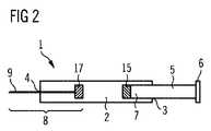
図2は、薬物送達デバイス1の実施態様の断面を模式的に示す。薬物送達デバイス1は第一の開口部3及び第二の開口部4を有する本体ユニット2を含む。薬物送達デバイス1は更に、その近位端6が本体ユニット2の外部に位置付けられ、そしてその遠位端7が本体ユニット2の内部に位置付けられるように配置されたプランジャー5を含む。プランジャー5は、それが本体ユニット2に対して遠位方向に可動であるように配置される。薬物送達デバイス1は更に、針9及び第二の連結エレメント17を含むニードルアセンブリー8を含む。プランジャー5は、その遠位端7に置かれる第一の連結エレメント15を含む。第一の連結エレメント15及び第二の連結エレメント17はそれらが互いに面するように配置される。 FIG. 2 schematically shows a cross section of an embodiment of the
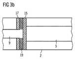
図3a及び3bは各々、薬物送達デバイス1の実施態様の模式的断面を示す。図3a/3bの左側に、第二の連結エレメント17及び第二の連結表面18を有する針9がある。図3a/3bの右側に、第一の連結エレメント15をその遠位端上に、そして第一の面連結表面16を第一の連結エレメント15上に有するプランジャー5が示される。二つの面連結表面16、18はそれらが互いに面するように配置される。 FIGS. 3 a and 3 b each show a schematic cross section of an embodiment of the
図3bにおいて、プランジャー5はそれまでのところ遠位方向に押されるので、第一の連結エレメント15は、ここでは第二の連結エレメント17に近接して二つの連結エレメント15、17の間に薄膜19が形成される。二つの連結エレメント15、17は二つの連結エレメントの各々と液膜19の間の接着力で互いに連結される。 In FIG. 3 b, the
図4a〜4eは、5つの異なる使用工程における、薬物送達デバイス1の実施態様の模式的断面を示す。 Figures 4a-4e show schematic cross-sections of an embodiment of the
図4aは、近位側での第一の開口部3及び遠位側での第二の開口部4を有する本体ユニット2を含む薬物送達デバイス1の実施態様の模式的断面を示す。薬物送達デバイス1は更に、針9、及び第二の面連結表面18を有する第二の連結エレメント17を含むニードルアセンブリー8を含む。薬物送達デバイス1は更に、遠位端7及び近位端6を有するプランジャー5を含む。プランジャー5の近位部分はスリーブ20によって囲まれる。スリーブ20とプランジャー5の間に置かれた、応力をかけられた状態で事前に圧縮されたばね21がある。プランジャー5は、遠位端7で、第一の面連結表面16を有する第一の連結エレメント15を含む。液体は第一の連結エレメント15と第二の連結エレメント17の間に置かれ、例えば、事前に充填されたシリンジの場合、液体は薬物を含有し得るであろう。図4aは、その出発位置において、例えば、シリンジ、好ましくは安全シリンジであり得るであろう薬物送達デバイスを示す。 FIG. 4a shows a schematic cross section of an embodiment of a
図4bは、図4aにおいて示される薬物送達デバイスの使用の中間工程における薬物送達デバイス1の断面を模式的に示す。図4bにおいて、プランジャー5は本体ユニット2に対して遠位方向に押される。 FIG. 4b schematically shows a cross section of the
図4cは、図4aにおいて示される薬物送達デバイス1の使用の中間工程における薬物送達デバイス1の断面を模式的に示す。プランジャー5を遠位方向に更に押すことによって、スリーブ20のスナップアーム22はプランジャーロッドラッチアーム23を内側に向かって押す。プランジャーロッドラッチアーム23はスリーブラッチ機構24に亘って内側にカチッと閉まる(snap)。 FIG. 4c schematically shows a cross section of the
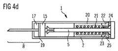
図4dは、図4aで示される薬物送達デバイス1の使用の中間段階における薬物送達デバイス1の横断面を概略的に示す。第一の及び第二の連結エレメント15、17はそれまでのところ一緒に押されてきたので、二つの連結エレメントの間には薄液膜19しか残っていない。それにより二つの連結エレメント15、17は液膜19に亘って接着連結状態になることができる。このように、プランジャー5及びニードルアセンブリー8は接着連結によって係合される。スナップアーム22は本体ユニット2の凹部25内にロックされる。従って、スリーブ20は本体ユニット2に連結され、そしてもはや本体ユニット2に対して動くことができない。プランジャー2のプランジャーロッドラッチアーム23はスリーブラッチ機構24を避けてその変形された状態で留まる。 FIG. 4d schematically shows a cross section of the
図4eは、図4aにおいて示される薬物送達デバイス1の使用の更なる工程における薬物送達デバイス1の断面を模式的に示す。図4eにおいて、プランジャー5は、事前に応力をかけられたばね21によって近位方向に本体ユニット2に対して引き戻されている。針9は、非常に遠くまで引き戻されているので、針9全体が本体ユニット2内部に置かれる。端部位置において、遠位端7は本体ユニット2と接触している。プランジャーロッドスナップアーム26は、それらがスリーブ20の遠位端表面における穴を通過する際に内側に向かってゆがむ。一旦、プランジャーロッドスナップアーム26がスリーブ20の中の穴から離れると、スリーブ20に対して後方に向かう位置においてプランジャー5をロックするためにプランジャーロッドスナップアーム26は外側に向かって曲がり、そして針9がそれ以上遠位方向に動くことを防ぐ。ここで端部位置において、ニードルアセンブリー8全体及び針9全体が本体ユニット2の内部に置かれる。ここで薬物送達デバイス1の使用者は、針9によって怪我することから保護される。 FIG. 4e schematically shows a cross section of the
第二の連結エレメント17と第二の開口部4の間に追加シールが置かれる更なる実施態様も可能である。この場合、第二の連結エレメント17及び針9のみが近位方向に引っ張られ、そしてシールがその場所に留まる実施態様が可能である。 Further embodiments in which an additional seal is placed between the second connecting
図5a〜5cは、セクションにおける薬物送達デバイスの実施態様の模式的断面を示す。三つの図は、小さくなった内径27のセクション、左側の針9のセクション、及び右側のプランジャー5のセクションを含む本体ユニット2を示す。針9の近位端におかれる第二の連結エレメント17が示される。この実施態様において、第二の連結エレメント17は面状に形成される。第二の連結エレメント17は第一の連結エレメント15の直径及び本体ユニット2の主内径の両方と比較してより小さな直径を有して形成される。針9の近位端は第二の連結エレメント17と並ぶ。図5aは、その出発位置において、例えば、シリンジ、好ましくは安全シリンジであり得るであろう薬物送達デバイス1を示す。 Figures 5a-5c show a schematic cross section of an embodiment of a drug delivery device in a section. The three figures show the
図5bは、プランジャー5が本体ユニット2に対して遠位方向に動かされるときの状況を示す。プランジャー5は非常に遠くまで遠位方向に押されるので、第一の連結エレメント15は、二つの連結エレメント15、17の間に薄膜19が形成される第二の連結エレメント17に非常に近くになる。二つの連結エレメント15、17は二つの連結エレメントの各々と液膜19の間の接着力に打ち勝って互いに連結される。 FIG. 5 b shows the situation when the
図5cは、次いでプランジャー5が本体ユニット2に対して近位方向に動かされるときの状況を示す。接着連結によって針9のニードルアセンブリー8及び第二の連結エレメント17が近位方向に動かされ、針を本体ユニット2内に引き込む。第二の連結エレメント17が近位で本体ユニット2内に動く際に、それは、小さくなった内径27を有する本体ユニット2のセクションとそれがもはや接触しない位置に迅速に達する。第二の連結エレメント17の直径は本体ユニット2の主直径より小さい。従って、一旦、第二の連結エレメントが、小さくなった内径27のセクションと接触することを停止すると、本体ユニット2は、第二の連結エレメント17及び針9の近位運動に対して更に抵抗することが全くなくなる。これによって、例えば、図3a/bにおいて示される実施態様と比べて、本体ユニット2内に針9を引くため二要求される力が大きく低減されるという著しい有利な点が供される。この力の低減の更なる有利な点は、第一の及び第二の連結エレメント15、17の間の接着連結に抗して作用する力が全くないことである。これによって、接着連結が失敗するかも知れないリスクが著しく低減される。 FIG. 5 c shows the situation when the
1)薬物送達デバイス
2)本体ユニット
3)第一の開口部
4)第二の開口部
5)プランジャー
6)近位端
7)遠位端
8)ニードルアセンブリー
9)針
10)内表面
11)チャンネル
12)外表面
13)近位端
14)遠位端
15)第一の連結エレメント
16)第一の面連結表面
17)第二の連結エレメント
18)第二の面連結表面
19)液膜
20)スリーブ
21)ばね
22)スリーブスナップアーム
23)プランジャーロッドラッチアーム
24)スリーブラッチ機構
25)凹部
26)プランジャーロッドスナップアーム
27)小さくなった内径セクション1) Drug delivery device 2) Body unit 3) First opening 4) Second opening 5) Plunger 6) Proximal end 7) Distal end 8) Needle assembly 9) Needle 10) Inner surface 11 ) Channel 12) outer surface 13) proximal end 14) distal end 15) first connecting element 16) first surface connecting surface 17) second connecting element 18) second surface connecting surface 19) liquid film 20) Sleeve 21) Spring 22) Sleeve snap arm 23) Plunger rod latch arm 24) Sleeve latch mechanism 25) Recess 26) Plunger rod snap arm 27) Reduced inner diameter section
Claims (16)
Translated fromJapanese−第一の開口部(3)及び第二の開口部(4)を有する本体ユニット(2);
−遠位端(7)が本体ユニット内部に位置付けられるように配置され、本体ユニット(2)に対して遠位方向に可動である、プランジャー(5);
−針(9)を含む、近位端(13)及び遠位端(14)を備えたニードルアセンブリー(8);
を含み、
ここで、ニードルアセンブリー(8)の近位端(13)及びプランジャー(5)の遠位端(7)が、それらが接着連結状態になり得るように構成される、
上記薬物送達デバイス(1)。A drug delivery device (1) comprising:
A body unit (2) having a first opening (3) and a second opening (4);
A plunger (5) arranged such that the distal end (7) is positioned inside the body unit and movable in a distal direction relative to the body unit (2);
A needle assembly (8) with a proximal end (13) and a distal end (14), including a needle (9);
Including
Here, the proximal end (13) of the needle assembly (8) and the distal end (7) of the plunger (5) are configured such that they can be in an adhesive connection.
The drug delivery device (1).
プランジャー(5)の遠位端(7)が第一の連結エレメント(15)を有する、上記薬物送達デバイス(1)。The drug delivery device (1) according to claim 1, comprising:
The drug delivery device (1), wherein the distal end (7) of the plunger (5) has a first coupling element (15).
第一の連結エレメント(15)がニードルアセンブリー(8)に面している第一の面連結表面(16)を有する、上記薬物送達デバイス(1)。A drug delivery device (1) according to claim 2, comprising:
The drug delivery device (1), wherein the first coupling element (15) has a first surface coupling surface (16) facing the needle assembly (8).
ニードルアセンブリー(9)が第二の連結エレメント(17)を有する、上記薬物送達デバイス(1)。The drug delivery device (1) according to any one of claims 1-3,
The drug delivery device (1), wherein the needle assembly (9) has a second coupling element (17).
第二の連結エレメント(17)が、プランジャー(5)に面している第二の面連結表面(18)を有する、上記薬物送達デバイス(1)。A drug delivery device (1) according to claim 4, comprising:
The drug delivery device (1), wherein the second coupling element (17) has a second surface coupling surface (18) facing the plunger (5).
第一の及び第二の面連結表面(16、18)が互いに平行に整列される、上記薬物送達デバイス(1)。A drug delivery device (1) according to claim 5, comprising:
The drug delivery device (1), wherein the first and second face connecting surfaces (16, 18) are aligned parallel to each other.
互いの上に押しつけられることによって、第一の及び第二の連結エレメント(15、17)が、ニードルアセンブリー(8)をプランジャー(5)と結合させる接着連結状態になる、上記薬物送達デバイス(1)。The drug delivery device (1) according to claim 5 or 6, comprising
The drug delivery device as described above, wherein the first and second coupling elements (15, 17) are brought into an adhesive coupling that couples the needle assembly (8) with the plunger (5) by being pressed onto each other. (1).
それらが接着連結状態になるとき、第一の及び第二の連結表面(16、18)の間に薄液膜(19)が存在する、上記薬物送達デバイス(1)。A drug delivery device (1) according to claim 7,
The drug delivery device (1), wherein there is a thin liquid film (19) between the first and second coupling surfaces (16, 18) when they become adhesively coupled.
プランジャー(5)が後退するとき、ニードルアセンブリー(8)が本体ユニット(2)内に少なくとも部分的に引き戻されるように構成される、上記薬物送達デバイス(1)。The drug delivery device (1) according to claim 7 or 8, comprising:
The drug delivery device (1), wherein the needle assembly (8) is configured to be at least partially retracted into the body unit (2) when the plunger (5) is retracted.
ニードルアセンブリー(8)がプランジャー(5)と接着連結状態になるとき、針(9)が本体ユニット(2)に対して動かないように構成される、上記薬物送達デバイス(1)。A drug delivery device (1) according to any one of claims 7 to 9, comprising
The drug delivery device (1) configured to prevent the needle (9) from moving relative to the body unit (2) when the needle assembly (8) is in adhesive connection with the plunger (5).
第一の及び第二の面連結表面(16、18)が同じ材料で作られる、上記薬物送達デバイス(1)。A drug delivery device (1) according to any one of claims 5 to 10, comprising
The drug delivery device (1), wherein the first and second surface coupling surfaces (16, 18) are made of the same material.
液膜(19)が第一の面連結表面(16)と第二の面連結表面(18)の間に形成される、上記薬物送達デバイス(1)。A drug delivery device (1) according to any one of claims 5 to 11, comprising
The drug delivery device (1), wherein a liquid film (19) is formed between the first surface coupling surface (16) and the second surface coupling surface (18).
本体ユニット(2)内に置かれそして薬物で充填されるチャンバーをさらに含む、上記薬物送達デバイス(1)。A drug delivery device (1) according to any one of claims 1 to 12, comprising
The drug delivery device (1), further comprising a chamber placed in the body unit (2) and filled with a drug.
ニードルアセンブリー(8)が本体ユニット(2)から取り外し可能でない、薬物送達デバイス(1)。A drug delivery device (1) according to any one of claims 1 to 13, comprising
A drug delivery device (1) wherein the needle assembly (8) is not removable from the body unit (2).
第二の連結エレメント(16)が初期には本体ユニット(2)の内表面と接触する位置にあり、そしてそれが本体ユニット(2)の内表面ともはや接触しない位置に本体ユニット(2)に対して近位方向に可動である、上記薬物送達デバイス(1)。A drug delivery device (1) according to any one of claims 1 to 14, comprising:
The second connecting element (16) is initially in a position in contact with the inner surface of the body unit (2) and in a position where it no longer contacts the inner surface of the body unit (2). Said drug delivery device (1) movable in a proximal direction relative to.
デバイスが薬剤で事前に充填される、上記薬物送達デバイス(1)。A drug delivery device (1) according to any one of claims 1 to 15, comprising:
The drug delivery device (1), wherein the device is pre-filled with a drug.
Applications Claiming Priority (3)
| Application Number | Priority Date | Filing Date | Title |
|---|---|---|---|
| EP09003279 | 2009-03-06 | ||
| EP09003279.8 | 2009-03-06 | ||
| PCT/EP2010/052790WO2010100245A1 (en) | 2009-03-06 | 2010-03-04 | Drug delivery device with retractable needle |
Publications (2)
| Publication Number | Publication Date |
|---|---|
| JP2012519513Atrue JP2012519513A (en) | 2012-08-30 |
| JP5586633B2 JP5586633B2 (en) | 2014-09-10 |
Family
ID=40863738
Family Applications (1)
| Application Number | Title | Priority Date | Filing Date |
|---|---|---|---|
| JP2011552457AExpired - Fee RelatedJP5586633B2 (en) | 2009-03-06 | 2010-03-04 | Drug delivery device with retractable needle |
Country Status (6)
| Country | Link |
|---|---|
| US (1) | US8702659B2 (en) |
| EP (1) | EP2403571A1 (en) |
| JP (1) | JP5586633B2 (en) |
| AU (1) | AU2010220259A1 (en) |
| CA (1) | CA2753994A1 (en) |
| WO (1) | WO2010100245A1 (en) |
Families Citing this family (13)
| Publication number | Priority date | Publication date | Assignee | Title |
|---|---|---|---|---|
| US20070202186A1 (en) | 2006-02-22 | 2007-08-30 | Iscience Interventional Corporation | Apparatus and formulations for suprachoroidal drug delivery |
| US8197435B2 (en) | 2006-05-02 | 2012-06-12 | Emory University | Methods and devices for drug delivery to ocular tissue using microneedle |
| JP5996544B2 (en) | 2010-10-15 | 2016-09-21 | クリアサイド・バイオメディカル・インコーポレーテッドClearside Biomedical Incorporated | Eye access device |
| KR20210133321A (en) | 2012-11-08 | 2021-11-05 | 클리어사이드 바이오메디컬, 인코포레이드 | Methods and devices for the treatment of ocular disease in human subjects |
| CA2911290C (en) | 2013-05-03 | 2021-07-27 | Clearside Biomedical, Inc. | Apparatus and methods for ocular injection |
| EP3003454B1 (en) | 2013-06-03 | 2020-01-08 | Clearside Biomedical, Inc. | Apparatus for drug delivery using multiple reservoirs |
| RU2710491C2 (en) | 2014-06-20 | 2019-12-26 | Клиасайд Байомедикал, Инк. | Device for drug injection into ocular tissue and method for drug injection into ocular tissue |
| USD750223S1 (en) | 2014-10-14 | 2016-02-23 | Clearside Biomedical, Inc. | Medical injector for ocular injection |
| US20170304115A1 (en)* | 2014-11-11 | 2017-10-26 | Eyevation, Llc | Delivery device |
| EP3413851B1 (en) | 2016-02-10 | 2023-09-27 | Clearside Biomedical, Inc. | Packaging |
| WO2017192565A1 (en) | 2016-05-02 | 2017-11-09 | Clearside Biomedical, Inc. | Systems and methods for ocular drug delivery |
| US10973681B2 (en) | 2016-08-12 | 2021-04-13 | Clearside Biomedical, Inc. | Devices and methods for adjusting the insertion depth of a needle for medicament delivery |
| US12090294B2 (en) | 2017-05-02 | 2024-09-17 | Georgia Tech Research Corporation | Targeted drug delivery methods using a microneedle |
Citations (2)
| Publication number | Priority date | Publication date | Assignee | Title |
|---|---|---|---|---|
| JPH07508670A (en)* | 1992-06-24 | 1995-09-28 | デュプラン インダストリーズ, インク. | Retractable needle structure |
| US20070250003A1 (en)* | 2006-04-03 | 2007-10-25 | Bare Rex O | Fluid activated retractable safety syringe |
Family Cites Families (2)
| Publication number | Priority date | Publication date | Assignee | Title |
|---|---|---|---|---|
| GB2341804B (en) | 1998-09-25 | 2003-02-12 | David William Parker | Improvements in or relating to hypodermic syringes |
| NZ595031A (en)* | 2007-07-02 | 2012-02-24 | Unitract Syringe Pty Ltd | Automatically retracting syringe with spring based mechanisim |
- 2010
- 2010-03-04CACA2753994Apatent/CA2753994A1/ennot_activeAbandoned
- 2010-03-04EPEP10709188Apatent/EP2403571A1/ennot_activeWithdrawn
- 2010-03-04JPJP2011552457Apatent/JP5586633B2/ennot_activeExpired - Fee Related
- 2010-03-04WOPCT/EP2010/052790patent/WO2010100245A1/enactiveApplication Filing
- 2010-03-04AUAU2010220259Apatent/AU2010220259A1/ennot_activeAbandoned
- 2010-03-04USUS13/202,440patent/US8702659B2/enactiveActive
Patent Citations (2)
| Publication number | Priority date | Publication date | Assignee | Title |
|---|---|---|---|---|
| JPH07508670A (en)* | 1992-06-24 | 1995-09-28 | デュプラン インダストリーズ, インク. | Retractable needle structure |
| US20070250003A1 (en)* | 2006-04-03 | 2007-10-25 | Bare Rex O | Fluid activated retractable safety syringe |
Also Published As
| Publication number | Publication date |
|---|---|
| EP2403571A1 (en) | 2012-01-11 |
| US20120095414A1 (en) | 2012-04-19 |
| JP5586633B2 (en) | 2014-09-10 |
| AU2010220259A1 (en) | 2011-09-22 |
| WO2010100245A1 (en) | 2010-09-10 |
| CA2753994A1 (en) | 2010-09-10 |
| US8702659B2 (en) | 2014-04-22 |
Similar Documents
| Publication | Publication Date | Title |
|---|---|---|
| JP5586633B2 (en) | Drug delivery device with retractable needle | |
| US11305068B2 (en) | Autoinjector | |
| US20240390604A1 (en) | Autoinjector with an inner plunger which disengages the outer plunger to retract the syringe carrier | |
| JP5608686B2 (en) | Drug delivery device with retractable needle | |
| US10857295B2 (en) | Medicament delivery device | |
| US9511194B2 (en) | Autoinjector | |
| US20220313926A1 (en) | Autoinjector | |
| CN104066466B (en) | auto injector | |
| JP5756471B2 (en) | Reconfigurable drive mechanism for drug delivery devices | |
| JP5794992B2 (en) | Drug delivery device with clearance compensation means | |
| JP5756468B2 (en) | Assembly for use in a drug delivery device | |
| JP5608687B2 (en) | Drug delivery device | |
| EP2906276B1 (en) | Medicament delivery device with use indicator | |
| CN104797283A (en) | Medicament delivery device with medicament delivery initiation indicator | |
| JP2013506460A (en) | Methods and assemblies for drug delivery devices | |
| HK1218400B (en) | Autoinjector | |
| HK1209667B (en) | Medicament delivery device with use indicator |
Legal Events
| Date | Code | Title | Description |
|---|---|---|---|
| A621 | Written request for application examination | Free format text:JAPANESE INTERMEDIATE CODE: A621 Effective date:20130221 | |
| A131 | Notification of reasons for refusal | Free format text:JAPANESE INTERMEDIATE CODE: A131 Effective date:20140128 | |
| A521 | Request for written amendment filed | Free format text:JAPANESE INTERMEDIATE CODE: A523 Effective date:20140428 | |
| TRDD | Decision of grant or rejection written | ||
| A01 | Written decision to grant a patent or to grant a registration (utility model) | Free format text:JAPANESE INTERMEDIATE CODE: A01 Effective date:20140624 | |
| A61 | First payment of annual fees (during grant procedure) | Free format text:JAPANESE INTERMEDIATE CODE: A61 Effective date:20140722 | |
| R150 | Certificate of patent or registration of utility model | Ref document number:5586633 Country of ref document:JP Free format text:JAPANESE INTERMEDIATE CODE: R150 | |
| LAPS | Cancellation because of no payment of annual fees |