JP2012517882A - High speed rotary atherectomy segmented polishing head and method for improving polishing efficiency - Google Patents
High speed rotary atherectomy segmented polishing head and method for improving polishing efficiencyDownload PDFInfo
- Publication number
- JP2012517882A JP2012517882AJP2011551050AJP2011551050AJP2012517882AJP 2012517882 AJP2012517882 AJP 2012517882AJP 2011551050 AJP2011551050 AJP 2011551050AJP 2011551050 AJP2011551050 AJP 2011551050AJP 2012517882 AJP2012517882 AJP 2012517882A
- Authority
- JP
- Japan
- Prior art keywords
- polishing head
- eccentric
- drive shaft
- proximal
- distal
- Prior art date
- Legal status (The legal status is an assumption and is not a legal conclusion. Google has not performed a legal analysis and makes no representation as to the accuracy of the status listed.)
- Granted
Links
Images


Classifications
- A—HUMAN NECESSITIES
- A61—MEDICAL OR VETERINARY SCIENCE; HYGIENE
- A61B—DIAGNOSIS; SURGERY; IDENTIFICATION
- A61B17/00—Surgical instruments, devices or methods
- A61B17/32—Surgical cutting instruments
- A61B17/3205—Excision instruments
- A61B17/3207—Atherectomy devices working by cutting or abrading; Similar devices specially adapted for non-vascular obstructions
- A61B17/320758—Atherectomy devices working by cutting or abrading; Similar devices specially adapted for non-vascular obstructions with a rotating cutting instrument, e.g. motor driven
- A—HUMAN NECESSITIES
- A61—MEDICAL OR VETERINARY SCIENCE; HYGIENE
- A61B—DIAGNOSIS; SURGERY; IDENTIFICATION
- A61B17/00—Surgical instruments, devices or methods
- A61B17/32—Surgical cutting instruments
- A61B2017/320004—Surgical cutting instruments abrasive
- A—HUMAN NECESSITIES
- A61—MEDICAL OR VETERINARY SCIENCE; HYGIENE
- A61B—DIAGNOSIS; SURGERY; IDENTIFICATION
- A61B17/00—Surgical instruments, devices or methods
- A61B17/32—Surgical cutting instruments
- A61B17/3205—Excision instruments
- A61B17/3207—Atherectomy devices working by cutting or abrading; Similar devices specially adapted for non-vascular obstructions
- A61B17/320758—Atherectomy devices working by cutting or abrading; Similar devices specially adapted for non-vascular obstructions with a rotating cutting instrument, e.g. motor driven
- A61B2017/320766—Atherectomy devices working by cutting or abrading; Similar devices specially adapted for non-vascular obstructions with a rotating cutting instrument, e.g. motor driven eccentric
Landscapes
- Health & Medical Sciences (AREA)
- Surgery (AREA)
- Life Sciences & Earth Sciences (AREA)
- Biomedical Technology (AREA)
- Nuclear Medicine, Radiotherapy & Molecular Imaging (AREA)
- Engineering & Computer Science (AREA)
- Vascular Medicine (AREA)
- Heart & Thoracic Surgery (AREA)
- Medical Informatics (AREA)
- Molecular Biology (AREA)
- Animal Behavior & Ethology (AREA)
- General Health & Medical Sciences (AREA)
- Public Health (AREA)
- Veterinary Medicine (AREA)
- Surgical Instruments (AREA)
Abstract
Translated fromJapaneseDescription
Translated fromJapanese本発明は、高速回転式アテローム切除術用デバイスを利用した動脈からの動脈硬化プラークの除去等の、身体通路から組織を除去するためのデバイスおよび方法に関する。 The present invention relates to devices and methods for removing tissue from body passageways, such as removal of arteriosclerotic plaque from an artery using a high speed rotating atherectomy device.
動脈および同様の身体通路における組織の除去または修復に使用するために、種々の技術および器具が開発されてきた。そのような技術および器具の主な目的は、患者の動脈における動脈硬化プラークの除去である。アテローム性動脈硬化は、患者の血管の内膜層(内皮の下)における脂肪性沈着物(アテローム)の蓄積を特徴とする。多くの場合、比較的軟性でコレステロールを多く含むアテローム様物質として初めに沈着したものは、経時的に硬化し、石灰化動脈硬化プラークになる。そのようなアテロームは、血流を制限するため、しばしば、狭窄性病変または狭窄と呼ばれ、閉塞物質は、狭窄物質と呼ばれる。処置せずに放置すると、そのような狭窄は、狭心症、高血圧症、心筋梗塞、脳卒中、および同等物を引き起こし得る。 Various techniques and instruments have been developed for use in removing or repairing tissue in arteries and similar body passages. The main purpose of such techniques and instruments is the removal of atherosclerotic plaque in the patient's arteries. Atherosclerosis is characterized by the accumulation of fatty deposits (atheromas) in the intimal layer of the patient's blood vessels (under the endothelium). In many cases, the first deposited as a relatively soft, cholesterol-rich atherogenic substance hardens over time and becomes a calcified arteriosclerotic plaque. Because such atheroma restricts blood flow, it is often referred to as a stenotic lesion or stenosis, and the occlusive material is referred to as a stenotic material. If left untreated, such stenosis can cause angina, hypertension, myocardial infarction, stroke, and the like.
回転式アテローム切除手技は、そのような狭窄物質を除去するための一般的な技術である。そのような手技は、冠状動脈における石灰化病変の開口を開始するために、最も頻繁に使用される。最も頻繁には、回転アテローム切除手技は単独で使用されないが、その後にバルーン血管形成手技が続き、順に、その後には、非常に頻繁に、開口した動脈の開存性の維持を支援するようにステントの留置が続く。非石灰化病変については、バルーン血管形成術は、最も頻繁には、動脈を開口するために単独で使用され、開口した動脈の開存性を維持するように、しばしばステントが留置される。しかしながら、研究によると、バルーン血管形成を受け、かつステントを動脈に留置した患者のうちの有意な割合の患者が、ステント再狭窄、すなわち、ステント内の瘢痕組織の過度な成長の結果として、一定の期間にわたって最も頻繁に発現するステントの閉塞を体験することが示されている。そのような状況では、アテローム切除手技が、ステントから過剰な瘢痕組織を除去するための好ましい手技であり(バルーン血管形成術はステント内であまり効果的ではない)、それにより、動脈の開存性を修復する。 Rotational atherectomy is a common technique for removing such stenotic material. Such a procedure is most often used to initiate the opening of calcified lesions in the coronary arteries. Most often, rotational atherectomy procedures are not used alone, but are followed by balloon angioplasty procedures, which in turn, very often help maintain the patency of open arteries. Stent placement continues. For non-calcified lesions, balloon angioplasty is most often used alone to open the artery, often with a stent placed to maintain the patency of the opened artery. However, studies have shown that a significant proportion of patients who have undergone balloon angioplasty and have placed a stent in an artery have consistently experienced stent restenosis, i.e., as a result of excessive growth of scar tissue within the stent. It has been shown to experience stent occlusion that occurs most frequently over a period of time. In such situations, an atherectomy procedure is the preferred procedure for removing excess scar tissue from the stent (balloon angioplasty is less effective within the stent), thereby patency of the artery To repair.
いくつかの種類の回転式アテローム切除術用デバイスが、狭窄物質の除去を試行するために開発されてきた。特許文献1(Auth)に示されるような一種類のデバイスでは、ダイヤモンド粒子等の研磨材で被覆されたバーが、可撓性駆動シャフトの遠位端に担持される。バーは、狭窄を横断して前進させられる間に、高速で回転する(典型的には、例えば、約150,000〜190,000rpmの範囲)。バーは、狭窄組織を除去するが、血流を閉塞する。いったんバーが狭窄を横断して前進させられると、動脈は、バーの最大外径と同等であるか、またはそれよりもわずかに大きい直径まで開口される。頻繁に、動脈を所望の直径まで開口するために、1つより多くのサイズのバーが利用されなければならない。 Several types of rotational atherectomy devices have been developed to attempt to remove stenotic material. In one type of device as shown in Patent Document 1 (Auth), a bar covered with an abrasive such as diamond particles is carried on the distal end of a flexible drive shaft. The bar rotates at high speed while being advanced across the stenosis (typically in the range of, for example, about 150,000 to 190,000 rpm). The bar removes stenotic tissue but occludes blood flow. Once the bar is advanced across the stenosis, the artery is opened to a diameter that is equal to or slightly larger than the maximum outer diameter of the bar. Frequently, more than one size bar must be utilized to open the artery to the desired diameter.
特許文献2(Shturman)は、拡大直径を有する駆動シャフトの一区分を伴う駆動シャフトを有する、別のアテローム切除術用デバイスを開示し、この拡大表面の少なくとも一区分は、駆動シャフトの研磨区分を規定するように研磨剤で被覆される。高速回転させられると、研磨区分は、動脈から狭窄組織を除去することが可能である。このアテローム切除術用デバイスは、その可撓性により、Authのデバイスに優る特定の利点を保有するが、デバイスが本質的に偏心性ではないため、駆動シャフトの拡大研磨表面の直径にほぼ等しい直径まで動脈を開口することしかできない。 U.S. Patent No. 6,057,028 (Shturman) discloses another atherectomy device having a drive shaft with a section of the drive shaft having an enlarged diameter, wherein at least one section of the enlarged surface comprises an abrasive section of the drive shaft. Coated with abrasive as specified. When rotated at high speed, the abrasive section can remove stenotic tissue from the artery. This atherectomy device has certain advantages over Auth's device due to its flexibility, but because the device is not inherently eccentric, the diameter is approximately equal to the diameter of the enlarged abrasive surface of the drive shaft Can only open the artery.
特許文献3(Shturman)は、拡大偏心部を伴う駆動シャフトを有する、アテローム切除術用デバイスを開示し、この拡大部の少なくとも一区分は、研磨材で被覆される。高速回転させられると、研磨区分は、動脈から狭窄組織を除去することが可能である。デバイスは、部分的には、高速動作中の軌道回転運動により、拡大偏心部の静止直径よりも大きい直径まで動脈を開口することが可能である。拡大偏心部が、一緒に結合されていない複数の駆動シャフトワイヤを備えるため、駆動シャフトの拡大偏心部は、狭窄内の配置中または高速動作中に屈曲し得る。この屈曲は、高速動作中に、より大きい直径の開口を可能にするが、実際に研磨される動脈の直径に対して所望されるよりも少ない制御を提供する場合もある。加えて、一部の狭窄組織が通路を完全に閉鎖する場合があるため、それを通してShturmanのデバイスを配置することができない。Shturmanは、研磨を達成するために、駆動シャフトの拡大偏心部が狭窄組織内に配置されることを要求するため、拡大偏心部が狭窄に入ることができない場合には、あまり効果的ではなくなる。特許文献3の開示は、参照によりその全体が本明細書に組み込まれる。 U.S. Patent No. 6,057,028 (Shturman) discloses an atherectomy device having a drive shaft with an enlarged eccentric portion, at least a section of which is coated with an abrasive. When rotated at high speed, the abrasive section can remove stenotic tissue from the artery. The device can partially open the artery to a diameter that is larger than the stationary diameter of the enlarged eccentric part by orbital rotational movement during high speed operation. Because the enlarged eccentric comprises a plurality of drive shaft wires that are not coupled together, the enlarged eccentric of the drive shaft can be bent during placement within the stenosis or during high speed operation. This flexion allows for a larger diameter opening during high speed operation, but may provide less control than is desired for the diameter of the artery that is actually polished. In addition, the Shturman device cannot be placed therethrough, as some stenotic tissue may completely close the passageway. Shturman requires the drive shaft's enlarged eccentrics to be placed in the stenotic tissue to achieve polishing, and is therefore less effective if the enlarged eccentrics cannot enter the stenosis. The disclosure of Patent Document 3 is incorporated herein by reference in its entirety.
特許文献4(Clement)は、好適な結合材料によってその外面の一部分に固定される研磨粒子の被覆を伴う、偏心組織切除バーを提供する。しかしながら、非対称バーが「熱または不均衡を補うために、高速焼灼デバイスで使用されるよりも低速で」回転させられることを、Clementが第3コラムの53〜55行において説明していることから、この構造は限定される。つまり、中実バーのサイズおよび質量の両方を考慮すると、アテローム切除手技中に使用される高速、すなわち、約20,000〜200,000rpmの範囲内の回転速度で、バーを回転させることは実行不可能である。本質的に、駆動シャフトの回転軸からオフセットされた質量中心により、有意な遠心力が発達し、動脈壁に過度な圧力を及ぼし、過度な熱および過度に大きい粒子を生成する。 U.S. Patent No. 6,057,037 (Clement) provides an eccentric tissue excision bar with a coating of abrasive particles secured to a portion of its outer surface by a suitable bonding material. However, since Clement explained in column 3 lines 53-55 that the asymmetric bar is rotated "slower than used in a high speed cautery device to compensate for heat or imbalance". This structure is limited. That is, considering both the size and mass of the solid bar, it is feasible to rotate the bar at the high speed used during the atherectomy procedure, i.e., a rotational speed in the range of about 20,000-200,000 rpm. Impossible. In essence, due to the center of mass offset from the axis of rotation of the drive shaft, significant centrifugal forces develop, exerting excessive pressure on the arterial wall, generating excessive heat and excessively large particles.
一般に、現在の組織除去要素は、非可撓性であり、結果として、蛇行性血管系を通して前進/後退させにくい場合がある、一体型の中実設計である。加えて、既知の設計は、典型的には、例えば、対称または非対称の楕円形または球形構成で、連続的な途切れのない研磨表面を備える。場合によっては、水圧ウェッジが現在の組織除去要素設計と動脈壁およびプラークとの間で形成し、研磨剤とプラークとの間の接触を低減し、結果として、手技の有効性を低減することが知られている。また、現在の設計の比較的平滑な研磨面は、研磨および/または切断有効性を最大限化しない。最後に、既知の比較的平滑な組織除去要素設計は、軟質プラークおよび/または石灰化していない病変および/またはびまん性病変に働きかける時に、予測不可能な長さのアテローム切除手技をもたらす。 In general, current tissue removal elements are one-piece solid designs that are inflexible and as a result may be difficult to advance / retract through tortuous vasculature. In addition, known designs typically comprise a continuous uninterrupted polishing surface, for example, in a symmetric or asymmetrical elliptical or spherical configuration. In some cases, a hydraulic wedge may form between the current tissue removal element design and the arterial wall and plaque, reducing contact between the abrasive and the plaque, and consequently reducing the effectiveness of the procedure. Are known. Also, the relatively smooth polishing surface of current designs does not maximize polishing and / or cutting effectiveness. Finally, known relatively smooth tissue removal element designs result in unpredictable length atherectomy procedures when working on soft plaques and / or non-calcified lesions and / or diffuse lesions.
したがって、選択可能かつカスタマイズ可能な数の個々の偏心研磨区分を伴う組織除去要素を有し、付加的な切断刃およびサンディング表面を備え、ならびに、研磨剤と動脈壁およびプラークとの間に存在する水圧ウェッジを破壊するための機構を提供する、アテローム切除術用デバイスの必要性が存在する。加えて、硬質プラークおよび軟質の石灰化されていないプラークの両方の効果的な研磨を可能にするようにカスタマイズすることができ、それにより、硬質、軟質、非石灰化および/またはびまん性狭窄組織を含む、そのような閉塞に働きかける時に、手技の成果および長さの予測可能性を増大させる、組織除去要素の必要性が存在する。さらに、全ての現在の設計は、固定量の質量を備え、結果として、固定回転直径を備える。したがって、存在する偏心質量に関してカスタマイズすることができる、研磨ヘッドの必要性が存在する。これは順に、偏心研磨ヘッドの回転直径のカスタマイズを可能にする。 Thus, it has a tissue removal element with a selectable and customizable number of individual eccentric abrasive sections, with an additional cutting blade and sanding surface, and between the abrasive and the arterial wall and plaque There is a need for an atherectomy device that provides a mechanism for breaking a hydraulic wedge. In addition, it can be customized to allow effective polishing of both hard and soft non-calcified plaques, thereby allowing hard, soft, non-calcified and / or diffuse stenotic tissue There is a need for a tissue removal element that increases the predictability of the outcome and length of the procedure when addressing such occlusions. In addition, all current designs have a fixed amount of mass, and consequently a fixed rotating diameter. Thus, there is a need for a polishing head that can be customized with respect to the existing eccentric mass. This in turn allows customization of the rotational diameter of the eccentric polishing head.
本発明は、種々の実施形態において、駆動シャフトに取り付けられ、近位および遠位円錐区分と離間して近接している、少なくとも1つの偏心研磨円筒形区分を備える、偏心研磨ヘッドを備える可撓性の細長い回転可能な駆動シャフトを有する、回転式アテローム切除術用システム、デバイス、および方法を提供する。各個々の研磨区分は、第1の組織除去表面、典型的には、石灰化した硬組織を研磨するように設計されている、外面上の研磨被覆と、石灰化していない軟組織を研磨するように設計されている、前後の表面上の研磨被覆とを備える。各研磨区分、ならびに集合的区分を備える研磨ヘッドは、駆動シャフトの回転軸から半径方向に離間する質量中心を有し、高速で動作された時に、拡大研磨ヘッドの外径よりも大きい直径まで狭窄性病変を開口するデバイスの能力を促進する。 The present invention, in various embodiments, is flexible with an eccentric polishing head, comprising at least one eccentric polishing cylindrical section attached to a drive shaft and spaced closely adjacent to proximal and distal conical sections. Rotational atherectomy systems, devices, and methods are provided that have an elongate rotatable drive shaft. Each individual polishing section is designed to polish a first tissue removal surface, typically an abrasive coating on the outer surface that is designed to polish calcified hard tissue and non-calcified soft tissue. And an abrasive coating on the front and back surfaces. A polishing head with each polishing section, as well as a collective section, has a center of mass radially spaced from the axis of rotation of the drive shaft and, when operated at high speed, narrows to a diameter larger than the outer diameter of the enlarged polishing head. Promotes the device's ability to open sexual lesions.
本発明の目的は、駆動シャフトに取り付けられる、好ましくは円盤形の少なくとも1つの偏心研磨円筒形区分、ならびに近位および遠位円錐区分を備える偏心研磨ヘッドを備える高速回転式アテローム切除術用デバイスを提供することであり、少なくとも1つの偏心研磨円筒形区分は、近位および遠位円錐区分の両方と離間して近接している。 It is an object of the present invention to provide a high speed rotary atherectomy device comprising at least one eccentric abrasive cylindrical section, preferably disc-shaped, and an eccentric abrasive head comprising proximal and distal conical sections attached to a drive shaft. In providing, the at least one eccentric abrasive cylindrical section is in close proximity to both the proximal and distal cone sections.
本発明の別の目的は、駆動シャフトに取り付けられる、好ましくは円盤形の少なくとも1つの偏心研磨円筒形区分、ならびに近位および遠位円錐区分を備える偏心研磨ヘッドを備える高速回転式アテローム切除術用デバイスを提供することであり、少なくとも1つの偏心研磨円筒形区分は、近位および遠位区分の両方と離間して近接し、円錐区分と、円筒形区分とを備える。 Another object of the present invention is for high speed rotary atherectomy comprising at least one eccentric abrasive cylindrical section, preferably disc shaped, attached to a drive shaft, and an eccentric abrasive head comprising proximal and distal conical sections. Providing a device, wherein the at least one eccentric abrasive cylindrical section is in close proximity to both the proximal and distal sections and comprises a conical section and a cylindrical section.
本発明の別の目的は、駆動シャフトに取り付けられる、少なくとも1つの偏心研磨円筒形区分と、近位および遠位区分と、少なくとも1つの円筒形区分の外面上および前後の表面上の研磨被覆と備える偏心研磨ヘッドを備える高速回転式アテローム切除術用デバイスを提供することであり、少なくとも1つの偏心研磨円筒形区分は、近位および遠位区分の両方と離間して近接し、研磨被覆は、石灰化および非石灰化および/または軟質狭窄組織の除去を最適化するように砂粒サイズを変化させる。 Another object of the present invention is to provide at least one eccentric abrasive cylindrical section, proximal and distal sections, and an abrasive coating on the outer and front and back surfaces of at least one cylindrical section, attached to the drive shaft. Providing a high speed rotary atherectomy device comprising an eccentric abrasive head, wherein the at least one eccentric abrasive cylindrical section is in close proximity to both the proximal and distal sections, the abrasive coating comprising: The sand grain size is varied to optimize calcified and non-calcified and / or soft stenotic tissue removal.
本発明の別の目的は、駆動シャフトに取り付けられる少なくとも1つの偏心研磨円筒形区分、ならびに近位および遠位区分を備える偏心研磨ヘッドを備える高速回転式アテローム切除術用デバイスを提供することであり、少なくとも1つの偏心研磨円筒形区分は、近位および遠位区分の両方と離間して近接し、アテローム切除術用デバイスの駆動シャフトの回転軸からオフセットされる質量中心をさらに備える。 Another object of the present invention is to provide a high speed rotary atherectomy device comprising at least one eccentric abrasive cylindrical section attached to a drive shaft, and an eccentric abrasive head comprising proximal and distal sections. The at least one eccentric abrasive cylindrical section further comprises a center of mass that is in close proximity to both the proximal and distal sections and offset from the axis of rotation of the drive shaft of the atherectomy device.
本発明の別の目的は、駆動シャフトに取り付けられる、少なくとも1つの偏心研磨円筒形区分、ならびに近位および遠位区分を備える偏心研磨ヘッドを備える高速回転式アテローム切除術用デバイスを提供することであり、少なくとも1つの偏心研磨円筒形区分は、近位および遠位区分の両方と離間して近接し、付加的な偏心研磨円筒形区分を追加するか、または研磨ヘッドから差し引き、したがって、研磨ヘッドを備える質量をカスタマイズし、駆動シャフトの回転軸からオフセットされた質量中心を操作することによって、高速回転中に研磨ヘッドのカスタマイズ可能な偏心性をさらに備える。 Another object of the present invention is to provide a high speed rotating atherectomy device comprising at least one eccentric abrasive cylindrical section attached to a drive shaft and an eccentric abrasive head comprising proximal and distal sections. And at least one eccentric abrasive cylindrical section is in close proximity to both the proximal and distal sections, and additional eccentric abrasive cylindrical sections are added or subtracted from the polishing head, and thus the polishing head And customizing eccentricity of the polishing head during high speed rotation by manipulating the center of mass offset from the rotational axis of the drive shaft.
本発明の別の目的は、駆動シャフトに取り付けられる、少なくとも1つの偏心研磨円筒形区分、ならびに近位および遠位区分を備える偏心研磨ヘッドを備える高速回転式アテローム切除術用デバイスを提供することであり、少なくとも1つの偏心研磨円筒形区分は、近位および遠位円錐区分の両方と離間して近接し、アテローム切除術用デバイスの駆動シャフトの回転軸からオフセットされる質量中心をさらに備え、少なくとも1つの偏心研磨円筒形区分の近位間隔は、蛇行性血管系を通した移動中に研磨ヘッドの可撓性を提供する。 Another object of the present invention is to provide a high speed rotating atherectomy device comprising at least one eccentric abrasive cylindrical section attached to a drive shaft and an eccentric abrasive head comprising proximal and distal sections. The at least one eccentric abrasive cylindrical section further comprises a center of mass that is in close proximity to both the proximal and distal conical sections and offset from the axis of rotation of the drive shaft of the atherectomy device; The proximal spacing of one eccentric abrasive cylindrical section provides the flexibility of the abrasive head during movement through the tortuous vasculature.
本発明の別の目的は、駆動シャフトに取り付けられる、少なくとも1つの偏心研磨円筒形区分、ならびに近位および遠位区分を有する高速回転式アテローム切除術用デバイスを提供することであり、少なくとも1つの偏心研磨円筒形区分は、近位および遠位区分の両方と離間して近接し、その間の完全な間隙であって、非石灰化および/または軟質狭窄組織を研磨する有効性を向上させる間隙を備える。 Another object of the present invention is to provide a high speed rotational atherectomy device having at least one eccentric abrasive cylindrical section, and proximal and distal sections, attached to a drive shaft. The eccentric abrasive cylindrical section is spaced closely adjacent to both the proximal and distal sections, and is a complete gap between them, improving the effectiveness of polishing non-calcified and / or soft stenotic tissue. Prepare.
本発明の別の目的は、駆動シャフトに取り付けられる、少なくとも1つの偏心研磨円筒形区分、ならびに近位および遠位区分を備える少なくとも1つの偏心研磨ヘッドを有する高速回転式アテローム切除術用デバイスを提供することであり、少なくとも1つの偏心研磨円筒形区分は、近位および遠位円錐区分の両方と離間して近接し、隣接する円筒形区分および/または円筒形区分ならびに近位および遠位区分の間の間隙は、組織除去表面と狭窄組織との間の水圧ウェッジを破壊することを促進する。 Another object of the present invention provides a high speed rotary atherectomy device having at least one eccentric abrasive cylindrical section attached to a drive shaft and at least one eccentric abrasive head comprising proximal and distal sections. The at least one eccentric abrasive cylindrical section is spaced closely adjacent to both the proximal and distal conical sections, the adjacent cylindrical and / or cylindrical sections and the proximal and distal sections of The interstices facilitate breaking the hydraulic wedge between the tissue removal surface and the stenotic tissue.
以下の図面および詳細説明は、本発明のこれらの実施形態および他の実施形態をより具体的に例示する。 The following drawings and detailed description illustrate more specifically these and other embodiments of the present invention.
以下の添付の図面に関連する本発明の種々の実施形態に関する以下の発明を実施するための形態を考慮して、本発明がより完全に理解され得る。
本発明は、種々の修正および代替形態に対応可能であるが、その仕様は、一例として図面に示され、本明細書で詳細に説明される。しかしながら、本発明を説明される特定の実施形態に限定することを意図しないことを理解されたい。反対に、本発明の精神および範囲内に入る全ての修正、同等物、および代替案を対象とすることを意図する。 While the invention is amenable to various modifications and alternative forms, specifics thereof are shown by way of example in the drawings and will be described in detail herein. It should be understood, however, that the intention is not to limit the invention to the particular embodiments described. On the contrary, the intention is to cover all modifications, equivalents, and alternatives falling within the spirit and scope of the invention.
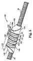
図1は、本発明による回転式アテローム切除術用デバイスの一実施形態を図示する。デバイスは、ハンドル部分10と、偏心研磨ヘッド100を有する細長い可撓性駆動シャフト20とを含む。本明細書で論議されるように、研磨ヘッド100は、その間に少なくとも1つの偏心円筒形区分を備える中間部とともに、近位および遠位区分を備える。細長いカテーテル13は、ハンドル部分10から遠位に延在する。駆動シャフト20は、当技術分野で公知であるように、螺旋コイル状ワイヤから構築され、研磨ヘッド28は、それに固定して取り付けられる。カテーテル13は、拡大研磨ヘッド28および研磨ヘッド28より遠位にある短いセクションを除いて、駆動シャフト20の長さの大部分が配置される管腔を有する。駆動シャフト20はまた、内側管腔を含み、駆動シャフト20をガイドワイヤ15上で前進および回転させる。流体供給ライン17は、冷却および潤滑溶液(典型的には、生理食塩水または別の生体適合性流体)をカテーテル13内に導入するために提供され得る。 FIG. 1 illustrates one embodiment of a rotary atherectomy device according to the present invention. The device includes a
ハンドル10は、望ましくは、駆動シャフト20を高速で回転させるためのタービン(または、同様の回転駆動機構)を含む。ハンドル10は、典型的には、管16を通して送達される圧縮空気等の動力源に接続され得る。一対の光ファイバケーブル25、代替として、単一の光ファイバケーブルが使用され得、また、タービンおよび駆動シャフト20の回転速度を監視するために提供され得る(そのようなハンドルおよび関連器具類に関する詳細は、当業界で周知であり、例えば、Authに発行された米国特許第5,314,407号で説明されている)。ハンドル10はまた、望ましくは、カテーテル13およびハンドルの本体に対してタービンおよび駆動シャフト20を前進および後退させるための制御ノブ11も含む。 The
図2および3は、駆動シャフト20Aの偏心拡大直径研磨部28Aを備える従来技術の研磨ヘッドの詳細を示す。駆動シャフト20Aは、拡大研磨部28A内のガイドワイヤ管腔19Aおよび中空空洞25Aを規定する、1つ以上の螺旋巻きワイヤ18を備える。中空空洞25Aをトラバースするガイドワイヤ15を除いて、中空空洞25Aは、実質的に空である。偏心拡大直径研磨部28Aは、狭窄の場所に対して、近位30A、中間35A、および遠位40A部分を含む。偏心拡大直径部28Aの近位部分30Aのワイヤ巻き31は、好ましくは、略一定の割合で遠位に段階的に増加する直径を有し、それにより、概して円錐形状を形成する。遠位部分40Aのワイヤ巻き41は、好ましくは、略一定の割合で遠位に段階的に減少する直径を有し、それにより、概して円錐形状を形成する。中間部分35Aのワイヤ巻き36には、駆動シャフト20Aの拡大偏心直径部28Aの近位および遠位円錐部分の間に円滑遷移を提供するように成形される、略凸状外面を提供するように次第に変化する直径が提供される。 2 and 3 show details of a prior art polishing head comprising an eccentrically enlarged
従来技術のデバイスに続いて、駆動シャフト28Aの偏心拡大直径研磨部の少なくとも一部(好ましくは、中間部分35A)は、組織を除去することが可能である外面を備える。駆動シャフト20Aの組織除去区分を規定するように、研磨材24Aの被覆を備える、組織除去表面37は、好適な結合剤26Aによって駆動シャフト20Aのワイヤ巻きに直接取り付けられて示されている。 Following the prior art device, at least a portion (preferably
図4は、図2および3の実質的に中空のデバイスと対照的に、Clementに対する米国特許第5,681,336号によって提供されるような、ガイドワイヤ15上で回転させられる、可撓性駆動シャフト20Bに取り付けられた中実非対称研磨バー28Bを採用する、別の従来技術の回転式アテローム切除術用デバイスを図示する。偏心組織切除バー28Bは、好適な結合材料26Bによってその外面の一部分に固定される、研磨粒子24Bの被覆を有する。しかしながら、非対称バーが「熱または不均衡を補うために、高速焼灼デバイスで使用されるよりも低速で」回転させられることを、Clementが第3コラムの53〜55行において説明していることから、この構造は限定された有用性を有する。つまり、中実バー型構造のサイズおよび質量の両方を考慮すると、アテローム切除手技中に使用される高速、すなわち、20,000〜200,000rpmで、そのようなバーを回転させることは実行不可能である。さらに、この従来技術のデバイスの研磨部は、比較的平滑であり、すなわち、溝が存在しない。結果として、この従来技術のデバイスは、非石灰化および/またな軟質狭窄を取り扱う時に効率的とはいえなくなる。 FIG. 4 is a flexible, rotated over
ここで図 5および6を参照すると、本発明の一実施形態が図示されている。偏心研磨ヘッド100は、 近位区分130、円筒形の中間部135、および遠位区分140といった、3つの部分を備え、中間部135は、近位および遠位区分130、140の間に位置し、近位および遠位区分130、140から離間している。 Referring now to FIGS. 5 and 6, one embodiment of the present invention is illustrated. The
近位区分130は、近位外面を備え、さらに、近位円錐部132と、近位円筒形部134とを備え、駆動シャフト20の上に載置され得る。中間部135は、近位区分130に隣接し、かつその遠位にある点において駆動シャフト20の上に載置される、少なくとも1つの偏心研磨円筒形区分102を備え、少なくとも1つの偏心研磨円筒形区分102は、近位区分130の円筒形部134から離間している。図示された実施形態では、3つの偏心研磨円筒形区分102が提供される。それぞれのそのような偏心研磨円筒形区分102は、隣接する円筒形区分102から離間している。遠位区分140は、遠位円錐部142と、遠位円筒形部140とを備え、中間部135に隣接し、かつその遠位にある点において駆動シャフト20の上に載置される。近位区分130および遠位区分140は、隣接する円筒形区分102から離間するように載置される。
近位区分130はさらに、近位内面136であって、偏心研磨ヘッド100の内部に対面し、具体的には隣接する円筒形区分102に対面する近位内面136を備える。同様に、遠位区分140はさらに、遠位内面146を備え、遠位内面146は、偏心研磨ヘッド100の内部に対面し、具体的には隣接する円筒形区分102に対面し、近位内面136とは反対方向に対面する。図に図示されるように、近位内面136および遠位内面146は、概して、互に対して反対方向に配向される。 The
当業者であれば、近位および/または遠位区分130、140は、上記で説明されるように、円錐部および円筒形部を備えてもよく、および/または区分130、140は、円錐外形または円筒外形であり得ることを認識するであろう。 One skilled in the art may have the proximal and / or
さらに、少なくとも1つの偏心研磨円筒形区分102のそれぞれは、外面104と、近位内面106pおよび遠位内面106dとを備え、内面106pおよび106dは、各円筒形区分の対向内面上に位置する。外面104および/または近位および遠位内面106p、106dは、その上に研磨剤を備え得る。当技術分野で周知であるように、図8−10で部分的に図示されるような研磨被覆26が塗布され得る。研磨砂粒サイズは、近位および遠位内面106p、106d上に塗布されるのとは外面104上で異なってもよいことが検討される。外面104が、硬質狭窄組織の除去に最適化される研磨砂粒サイズを備え得る一方で、近位および/または遠位内面106p、106dは、軟質の非石灰化および/またはびまん性狭窄組織に最適化される研磨砂粒サイズを備え得る。 Further, each of the at least one eccentric polished
少なくとも1つの円筒形区分102ならびに近位および遠位区分130、140の離間載置の結果として、可撓性間隙Gが、近位内面146と隣接する円筒形区分の対向内面106pとの間、ならびに遠位外面136と隣接する円筒形区分の対向遠位内面106dとの間に存在する。したがって、単一の円筒形区分102を伴う最も単純な場合、合計2つの可撓性間隙Gが存在する。上記で論議される離間構成で相互に隣接して整合される2つの円筒形区分102を伴う場合、合計3つの間隙Gが存在し、近位内面136と隣接する円筒形区分の対向近位内面106pとの間の第1の間隙G、遠位外面146と隣接する筒形区分の対向遠位内面106dとの間の第2の間隙G、最近位円筒形区分の対向遠位内面106dと最遠位円筒形区分の対向近位内面106pとの間の第3の間隙Gである。3つの円筒形区分102を伴う場合が図5および6に図示されており、先述の論議と一致する4つの可撓性間隙Gを備える。したがって、本発明は、少なくとも2つの可撓性間隙Gを有する、偏心研磨ヘッド100を備える。本発明の偏心研磨ヘッドの所与の実施形態における可撓性間隙Gの数は、式「N+1」を備え、式中、Nは、円筒形区分102の数である。 As a result of the spaced mounting of the at least one
少なくとも2つの可撓性間隙Gの存在は、偏心研磨ヘッド100および回転式アテローム切除術用デバイス上の極めて望ましい性能特性を与える。第1に、間隙Gは、駆動シャフトが自由に屈曲することを可能にし、したがって、駆動シャフトおよび研磨ヘッド100が患者の蛇行性血管系に容易に挿入され、そこから引き出されることを可能にする。この挿入の容易性は、より非外傷性の手技を提供する。 The presence of at least two flexible gaps G provides highly desirable performance characteristics on the
第2に、上記で説明されるように、特異的な研磨砂粒サイズが、近位および遠位内面106p、106dと対比して円筒形区分の外面104とに採用され得る。したがって、外面104の研磨剤が、硬質狭窄組織の除去に最適化され得る一方で、近位および遠位内面106p、106dは、軟質の非石灰化および/またはびまん性狭窄組織に最適化される研磨剤を備え得る。後者の場合、例えば、研磨ヘッド100が操作者によって狭窄内で近位または遠位に移動させられるにつれて、軟組織が、外面104による圧縮後に拡張し、可撓性間隙Gの中へある距離で延在し得る。間隙Gの近位および遠位内面106p、106d上の軟組織除去に最適化される研磨剤の存在は、その除去を向上させる。 Second, as explained above, a specific abrasive grain size can be employed on the
第3に、可撓性間隙Gは、比較的平滑な表面の研磨ヘッドが狭窄および/または動脈壁に対して高速で回転すると生じることが知られている、水圧ウェッジを崩壊および/または破壊するための機構および方法を提供する。したがって、間隙Gは、研磨ヘッド100、特に外面104と狭窄との間の増大した接触を推進する。したがって、本発明の研磨ヘッド100は、研磨効率および有効性を向上させる。 Third, the flexible gap G collapses and / or breaks the hydraulic wedge, which is known to occur when a relatively smooth surface polishing head rotates at high speed relative to the stenosis and / or arterial wall. Mechanisms and methods are provided. Thus, the gap G drives increased contact between the polishing
第4に、可撓性間隙Gは、高速回転中に研磨ヘッド100のある程度の屈曲を可能にする。これは、手技中に研磨効率を向上させ、外傷を減少させる。加えて、可撓性間隙Gは、研磨ヘッド100が、より自然で、したがって、より安定した振動周波数を達成し実現することを可能にし得る。 Fourth, the flexible gap G allows a certain degree of bending of the polishing
また、本発明の研磨ヘッド100は、一体型の従来技術の研磨ヘッドよりも多くの研磨表面積を備える。近位および遠位内面106p、106dの研磨表面26は、既知の一体型デバイスでは利用可能ではない、大量の表面積を追加する。この追加表面積は、回転式アテローム切除手技の効率を増加させ、手技時間を削減する。偏心研磨円筒形区分100の数が可変あり、すなわち、少なくとも1つの円筒形区分100が使用され得るため、本発明のデバイス100の研磨表面積はカスタマイズ可能であり、単純に円筒形区分100を追加するか、または差し引くこと、および/または研磨剤で内面および/または外面106p、106dを被覆しないことを選択することによって、所望に応じて増加または減少させられ得る。 Also, the polishing
当技術分野で十分理解されるように、研磨材は、ダイヤモンド粉末、溶融石英、窒化チタン、炭化タングステン、酸化アルミニウム、炭化ホウ素、または他のセラミック材料等の、任意の好適な材料であり得る。好ましくは、研磨材は、好適な結合剤によって組織除去表面に直接取り付けられるダイヤモンドチップ(またはダイヤモンドダスト粉末)から成る。そのような取付は、従来の電気めっきまたは融合技術(例えば、米国特許第4,018,576号を参照)等の周知の技術を使用して達成され得る。代替的に、外部組織切除表面は、好適な研磨組織切除表面を提供するように、中間部135、近位および/または遠位区分130、140の外面の機械的または化学的粗化を含み得る。さらに別の変形例では、外面は、小さいが効果的な研磨表面を提供するように、エッチングまたは(例えば、レーザで)切断され得る。他の類似技術も、好適な組織除去表面を提供するために利用され得る。 As is well understood in the art, the abrasive can be any suitable material, such as diamond powder, fused quartz, titanium nitride, tungsten carbide, aluminum oxide, boron carbide, or other ceramic material. Preferably, the abrasive comprises a diamond tip (or diamond dust powder) that is attached directly to the tissue removal surface by a suitable binder. Such attachment can be accomplished using well known techniques such as conventional electroplating or fusion techniques (see, eg, US Pat. No. 4,018,576). Alternatively, the external tissue excision surface may include mechanical or chemical roughening of the outer surface of the
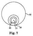
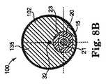
図5〜7で最も良く図示されるように、少なくとも部分的に封入された管腔またはスロット23が、当業者に周知の方式で研磨ヘッド100を駆動シャフト20に固定するために、駆動シャフト20の回転軸21に沿って、偏心研磨ヘッド100を縦方向に通って提供され得る。したがって、近位および遠位区分130、140は、図7および図8A〜8Cに示されるような少なくとも1つの円筒形区分120のように、このようにして駆動シャフト20に固定される。図7は、部分的に封入された管腔23を伴い、駆動シャフト20に取り付けられた1つの円筒形区分102を図示する。近位および遠位区分130、140は、同様に、少なくとも部分的に封入された管腔23を備え得る。近位および遠位区分130、140および/または少なくとも1つの円筒形区分100の代替実施形態は、例えば、図8A−8Cの断面図に示されるような完全に封入された管腔23を備え得る。 As best illustrated in FIGS. 5-7, an at least partially enclosed lumen or
図5および6の実施形態は、対称形状および長さである近位および遠位130、140区分、ならびに中間部135まで至る円錐部の同等な傾斜132、142を図示する。代替実施形態は、非対称外形を作成するように、近位区分130または遠位区分140の長さを増加させてもよい。一般に、図5および6に図示されるような本発明の研磨ヘッド100の対称性が好ましいが、代替実施形態は、近位および/または遠位区分130、140のより大きい、または小さい傾斜の程度を備え得る。加えて、近位および/または遠位区分130、140および/または中間部35は、より長い、または短い長さを有し得る。それぞれのそのような組み合わせは、本発明の範囲内である。 The embodiment of FIGS. 5 and 6 illustrates proximal and distal 130,140 sections that are symmetrical in shape and length, and equivalent slopes 132,142 of the cone leading up to the
上記で説明されるように、ある実施形態では、近位および/または遠位区分130、140が、円錐部132、140および/または円筒形部134、144を備える一方で、中間部135は、円筒形である。図7および8A−8Cに図示されるように、この幾何学的構成は、駆動シャフト20の縦回転軸21から幾何学的および半径方向に離間される質量中心32を伴う、本発明の偏心研磨ヘッド100を提供することに少なくとも部分的に関与する。図に図示されるように、各偏心円筒形区分102は、駆動シャフト20の回転軸21からオフセットされる質量中心32を備える。加えて、近位および遠位部130、140は、駆動シャフト20の回転軸21からオフセットされる質量中心を備える。駆動シャフトの回転軸21から質量中心32をオフセットすることにより、偏心研磨ヘッド100に、高速回転中に偏心研磨ヘッド100の公称直径よりも大幅に大きい直径まで動脈を開口することを可能にする偏心性を提供する。好ましくは、開口直径は、偏心研磨ヘッド100の公称静止直径の少なくとも2倍大きい。加えて、質量中心32のそのようなオフセットは、例えば、異なる密度を有する2種類以上の材料を使用することによって、中間部135における質量の量および質量の場所を変化させることによって向上させられ、操作され、制御され得る。 As described above, in certain embodiments, the proximal and / or
本明細書で使用されるように、「偏心」および「偏心性」という言葉は、偏心研磨ヘッド100の幾何学的中心と駆動シャフト20の回転軸21との間の場所の差異、または偏心研磨ヘッド100の質量中心32と駆動シャフト20の回転軸21との間の場所の差異を指すように定義され、本明細書で使用されることを理解されたい。いずれか一方のそのような差異は、適正な回転速度で、偏心研磨ヘッド100が、偏心研磨ヘッド100の公称直径よりも大幅に大きい直径まで狭窄を開口することを可能にする。個々の円筒形区分102ならびに近位および遠位区分130、140が可撓性間隙Gによって分離されるため、研磨ヘッド100は、高速回転中に、わずかに屈曲し得る。この屈曲能力は、研磨効率を向上させるのに役立ち得る。加えて、偏心研磨ヘッド100は、高速回転中に、中実の一体型研磨ヘッドよりも有利である、自然な振動周波数を達成し得る。 As used herein, the terms “eccentric” and “eccentric” refer to the location difference between the geometric center of the
本発明の回転式アテローム切除術用デバイスの研磨ヘッド100は、ステンレス鋼、タングステン、および/または同様の材料で構築され得る。 The polishing
図8A−8Cは、偏心研磨ヘッド100が管腔23を介して駆動シャフト20に固定して取り付けられ、駆動シャフト20がガイドワイヤ15上で前進させられる、図5および6に示された偏心研磨ヘッド100の3つの断面薄片(横断面図として示されている)の質量中心32の位置を描写する。明白となるように、近位および/または遠位区分130、140ならびに少なくとも1つの円筒形区分100はそれぞれ、駆動シャフト20の回転軸21に対する質量中心32の位置を備える。図8Bは、偏心研磨ヘッド100がその最大断面直径(この実施形態では、偏心拡大研磨ヘッド100の少なくとも1つの円筒形区分102の最大直径である)を有する位置で得られ、図 8Aおよび8Cは、それぞれ、偏心研磨ヘッド100の近位および遠位区分130、140の断面図である。これらの断面薄片のそれぞれでは、質量中心32は、駆動シャフト20の回転軸21から離間し、駆動シャフト20の回転軸は、ガイドワイヤ15の中心と一致する。各断面薄片の質量中心32はまた、そのような断面薄片の幾何学中心にも概して一致するが、当業者であれば理解するように、異なる密度を伴う材料を採用することにより、幾何学中心から離れた質量中心32の移動を可能にし得る。図8Bは、研磨ヘッド100の最大断面直径を備える、少なくとも1つの円筒形区分102の断面薄片を図示し、質量中心32および幾何学中心の両方は、近位および遠位区分130、140と比較して、駆動シャフト20の回転軸21から最も遠くに位置する(すなわち、最大限に離間する)。 FIGS. 8A-8C show the eccentric polishing shown in FIGS. 5 and 6 in which the
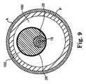
図9は、ガイドワイヤ20および取り付けられた研磨ヘッド100が、ガイドワイヤ15上で前進させられ、狭窄が実質的に開口された後の動脈「A」内で「静止」位置にある、本発明の偏心研磨ヘッド100の少なくとも1つの円筒形区分102を通る断面図を描写し、したがって、デバイスの公称直径を十分上回る直径まで狭窄を開口するデバイスの能力を図示する。 FIG. 9 shows the present invention in which the
本発明の偏心研磨ヘッド100の公称直径よりも大きい直径まで、動脈における狭窄を開口することができる程度は、偏心研磨ヘッド100の形状、偏心研磨ヘッド100の質量、その質量分布、したがって駆動シャフトの回転軸に対する研磨ヘッド100内の質量中心の位置、および回転速度を含むが、それらに限定されない、いくつかのパラメータに依存する。ここで当業者にとって明白となるべきであるように、研磨ヘッド100の質量および質量中心の場所は、所望の質量の量および質量中心の場所を達成するように、円筒形区分102を追加または除去することによって、本発明を使用して操作および制御され得る。 The degree to which a stenosis in an artery can be opened to a diameter larger than the nominal diameter of the
回転速度は、偏心研磨ヘッド100の研磨表面26が狭窄組織に対して押圧される遠心力を決定する際の重要因子であり、それによって、操作者は、組織切除の割合を制御することが可能になる。回転速度の制御も、ある程度は、デバイスが狭窄を開口する最大直径の制御を可能にする。出願者らはまた、研磨表面26が狭窄組織に対して押圧される力を確実に制御する能力が、操作者が組織除去の割合をより良好に制御することを可能にするだけでなく、除去されている粒子のサイズのより良好な制御を提供することも発見している。 The rotational speed is an important factor in determining the centrifugal force with which the polishing
図10〜11は、本発明の偏心研磨ヘッド100の種々の実施形態が取る略螺旋状軌道経路を示し、研磨ヘッド100は、その上で研磨ヘッド100が前進させられているガイドワイヤ15に対して示されている。螺旋状経路のピッチは、例証目的のために誇張されており、実際は、偏心研磨ヘッド100の各螺旋状経路は、円筒形区分102の外面上に位置する研磨剤26を介して、組織の非常に薄い層を除去するだけであり、狭窄を完全に開口するように、デバイスが狭窄を横切って繰り返し前後に移動させられる、すなわち、平行移動させられると、多くのそのような螺旋状通路が偏心研磨ヘッド100によって作られる。図10は、本発明の回転式アテローム切除術用デバイスの偏心研磨ヘッド100の3つの異なる回転位置を概略的に示す。各位置において、偏心研磨ヘッド100の研磨表面は、除去されるプラーク「P」に接触し、3つの位置は、プラーク「P」との3つの異なる接触点によって識別され、これらの点は、B1、B2、およびB3として図中で指定されている。各点において、それは、組織に接触する偏心拡大研磨ヘッド100の研磨表面の概して同じ部分であり、つまり、駆動シャフトの回転軸から半径方向に最も遠位にある、円筒形区分102の外面104上の研磨表面の部分であることに留意されたい。 10-11 illustrate the generally helical trajectory path taken by various embodiments of the
いずれの特定の動作の理論にも拘束されることを希望しないが、駆動シャフト20の回転軸21から質量中心32をオフセットすることにより、偏心研磨ヘッド100の「軌道」運動を生じ、「軌道」の直径は、とりわけ、駆動シャフトの回転速度、および採用される少なくとも1つの円筒形区分102の数、ならびにその質量および質量分布を変化させることによって制御可能であると、出願者らは考える。出願者らは、駆動シャフト20の回転速度および/または円筒形区分102の数を変化させることによって、狭窄の表面に対して偏心研磨ヘッド100の円筒形区分102の外面104上の研磨表面26を押し進める遠心力を制御できることを、実験的に実証している。遠心力は、以下の公式によって決定することができる。 Although not wishing to be bound by any particular theory of operation, offsetting the center of
FC=mΔx(πn/30)2
式中、Fcは、遠心力であり、mは、偏心研磨ヘッド100の質量であり、Δxは、偏心研磨ヘッド100の質量中心32と駆動シャフト20の回転軸21との間の距離であり、nは、毎分回転数(rpm)の回転速度である。この力Fcを制御することによって、組織を切除する速度に対する制御、デバイスが狭窄を開口する最大直径に対する制御、および切除される組織の粒子サイズに対する改良された制御が提供される。FC = mΔx (πn / 30)2
In the formula, Fc is a centrifugal force, m is a mass of the
本発明の研磨ヘッド100は、従来技術の高速アテローム切除術用研磨デバイスよりも多くの質量を備え得る。結果として、高速回転中に、より大きな軌道、すなわち、より大きな回転直径が達成され得、それは順に、従来技術のデバイスよりも小さい研磨ヘッドの使用を可能にする。さらに、偏心研磨ヘッド100の追加可撓性が、挿入の容易性およびより非外傷性の手技を可能にする。 The polishing
動作的に、本発明の回転式アテローム切除術用デバイスを使用して、偏心研磨ヘッド100は、狭窄を通って遠位および近位に繰り返し移動させられる。デバイスの回転速度を変更することによって、操作者は、円筒形区分102の外面上の研磨剤が狭窄組織に対して押圧される力を制御することが可能であり、それにより、プラーク除去の速度ならびに除去される組織の粒径をより良好に制御することが可能である。加えて、狭窄組織を通して研磨ヘッド100を遠位および近位に移動させること、すなわち、平行移動させることによって、軟質の非石灰化および/またはびまん性組織は、可撓性間隙Gを充填するように拡張し得、それにより、そのような組織の研磨および除去に最適化された近位および/または遠位表面106p、106d上に位置する研磨剤に、この組織をさらす。狭窄が、偏心研磨ヘッド100の公称直径よりも大きい直径まで開口させられていることから、冷却用溶液および血液は、拡大研磨ヘッドの周囲を絶えず流動することができる。加えて、可撓性間隙Gは、研磨ヘッド100の周囲の流体流動のためのチャネルを提供する。 In operation, using the rotary atherectomy device of the present invention, the
偏心拡大研磨ヘッド100は、約1.0mmから約3.0mmの間の最大断面直径を備え得る。したがって、偏心拡大研磨ヘッドは、1.0mm、1.25mm、1.50mm、1.75mm、2.0mm、2.25mm、2.50mm、2.75mm、および3.0mmを含むが、それらに限定されない断面直径を備え得る。当業者であれば、上記に列挙する断面直径内の0.25mmの増分は例示的にすぎず、本発明が、例示的列挙によって限定されず、結果として、断面直径における他の増分が可能であり、かつ本発明の範囲内にあることを容易に認識するであろう。 The eccentric enlarged polishing
上記で説明されるように、偏心研磨ヘッド100の偏心性がいくつかのパラメータに依存しているため、出願者らは、駆動シャフト20の回転軸21と、偏心研磨ヘッド100の最大断面直径の位置で、すなわち、少なくとも1つの円筒形区分102を通して得られた、横断面図の面の幾何学的中心との間の距離に関して、以下の設計パラメータが考慮され得ることを発見している。約1.0mmから約1.5mmの間の最大断面直径を伴う偏心拡大研磨ヘッドを有するデバイスでは、望ましくは、幾何学的中心は、駆動シャフトの回転軸から少なくとも約0.02mmの距離、好ましくは、少なくとも約0.035mmの距離だけ離間するべきであり、約1.5mmから約1.75mmの間の最大断面直径を伴う偏心拡大研磨ヘッドを有するデバイスでは、望ましくは、幾何学的中心は、駆動シャフトの回転軸から少なくとも約0.05mmの距離、好ましくは、少なくとも約0.07mmの距離、最も好ましくは、少なくとも約0.09mmの距離だけ離間するべきであり、約1.75mmから約2.0mmの間の最大断面直径を伴う偏心拡大研磨ヘッドを有するデバイスでは、望ましくは、幾何学的中心は、駆動シャフトの回転軸から少なくとも約0.1mmの距離、好ましくは、少なくとも約0.15mmの距離、最も好ましくは、少なくとも約0.2mmの距離だけ離間するべきであり、2.0mm以上の最大断面直径を伴う偏心拡大研磨ヘッドを有するデバイスでは、望ましくは、幾何学的中心は、駆動シャフトの回転軸から、少なくとも約0.15mmの距離、好ましくは、少なくとも約0.25mmの距離、最も好ましくは、少なくとも約0.3mmの距離だけ離間するべきである。 As explained above, since the eccentricity of the
設計パラメータはまた、質量中心の場所に基づくことも可能である。約1.0mmから約1.5mmの間の最大断面直径、すなわち、少なくとも1つの円筒形区分102の最大直径を伴う偏心研磨ヘッド100を有するデバイスでは、望ましくは、質量中心は、駆動シャフトの回転軸から、少なくとも約0.013mmの距離、好ましくは、少なくとも約0.02mmの距離だけ離間するべきであり、約1.5mmから約1.75mmの間の最大断面直径を伴う偏心研磨ヘッド100を有するデバイスでは、望ましくは、質量中心は、駆動シャフトの回転軸から、少なくとも約0.03mmの距離、好ましくは、少なくとも約0.05mmの距離だけ離間するべきであり、約1.75mmから約2.0mmの間の最大断面直径を伴う偏心拡大研磨ヘッドを有するデバイスでは、望ましくは、質量中心は、駆動シャフトの回転軸から、少なくとも約0.06mmの距離、好ましくは、少なくとも約0.1mmの距離だけ離間するべきであり、2.0mm以上の最大断面直径を伴う偏心拡大研磨ヘッドを有するデバイスでは、望ましくは、質量中心が、駆動シャフトの回転軸から、少なくとも約0.1mmの距離、好ましくは、少なくとも約0.16mmの距離だけ離間するべきである。 Design parameters can also be based on the location of the center of mass. For devices having an
好ましくは、設計パラメータは、偏心研磨ヘッド100が約20,000rpmよりも大きい回転速度において静止ガイドワイヤ15(ガイドワイヤのいずれの大幅な移動も妨げるよう十分張り詰めて保たれる)上で回転させられると、少なくとも1つの円筒形区分102の外面104の少なくとも一部分が、偏心研磨ヘッド100の最大公称直径よりも大きい、すなわち、少なくとも1つの円筒形区分102の直径よりも大きい直径を有する経路(そのような経路が完全に規則的であるか円形であるか否かにかかわらず)を通って回転し得るほど、偏心研磨ヘッド100が十分に偏心性であるように選択される。例えば、制限するものではないが、約1.5mmから約1.75mmの間の最大直径を有する偏心研磨ヘッド100では、研磨ヘッド100の少なくとも一部分は、偏心拡大研磨ヘッド100の最大公称直径よりも少なくとも約10%大きい、好ましくは、偏心研磨ヘッド100の最大公称直径よりも少なくとも約15%大きい、最も好ましくは、研磨ヘッド100の最大公称直径よりも少なくとも約20%大きい直径を有する、経路を通って回転し得る。約1.75mmから約2.0mmの間の最大直径を有する偏心研磨ヘッド100では、研磨ヘッド100の少なくとも一部分は、研磨ヘッド100の最大公称直径よりも少なくとも約20%大きい、好ましくは、研磨ヘッド100の最大公称直径よりも少なくとも約25%大きい、最も好ましくは、研磨ヘッド100の最大公称直径よりも少なくとも約30%大きい直径を有する、経路を通って回転し得る。少なくとも約2.0mmの間の最大直径を有する偏心研磨ヘッド100では、研磨ヘッド100の少なくとも一部分は、偏心研磨ヘッド100の最大公称直径よりも少なくとも約30%大きい、好ましくは、拡大研磨ヘッド100の最大公称直径よりも少なくとも約40%大きい最直径を有する、経路を通って回転し得る。 Preferably, the design parameters are such that the
好ましくは、設計パラメータは、拡大研磨ヘッド100が約20,000rpmよりも大きい回転速度において静止ガイドワイヤ15上で回転させられると、その研磨ヘッド100の少なくとも一部分が、静止研磨ヘッド100の最大公称直径よりも大幅に大きい、すなわち、少なくとも1つの円筒形区分102の直径よりも大幅に大きい直径を伴う経路(そのような経路が完全に規則的であるか円形であるか否かにかかわらず)を通って回転するほど、拡大研磨ヘッド100が十分に偏心性であるように選択される。種々の実施形態では、本発明は、静止研磨ヘッド100の最大公称直径よりも増分的に少なくとも約50%から約400%大きい最大直径を伴う、実質的軌道経路を規定することが可能である。望ましくは、そのような軌道経路は、静止偏心拡大研磨ヘッド100の最大公称直径よりも少なくとも約200%から約400%大きい、すなわち、少なくとも1つの円筒形区分102の直径よりも大幅に大きい、最大直径を備える。 Preferably, the design parameters are such that when the
本発明は、上記で説明される特定の実施例に限定されると考えられるべきではなく、むしろ、本発明の全側面を網羅すると理解されるべきである。本発明が適用可能であり得る、種々の修正、同等のプロセス、ならびに多数の構造は、本明細書を考察することによって、本発明を対象とする当業者にとって容易に明白になるであろう。 The present invention should not be considered limited to the particular embodiments described above, but rather should be understood to cover all aspects of the invention. Various modifications, equivalent processes, and numerous structures to which the present invention may be applicable will be readily apparent to those of skill in the art to which the present invention is directed upon review of the specification.
Claims (27)
Translated fromJapanese該動脈の直径よりも小さい最大直径を有するガイドワイヤと、
該ガイドワイヤ上で前進可能である可撓性の細長い回転可能な駆動シャフトであって、該駆動シャフトは、回転軸を有する、駆動シャフトと、
該駆動シャフトに取り付けられる偏心研磨ヘッドであって、該研磨ヘッドは、近位部と、遠位部と、該近位部と該遠位部との間の中間部と、少なくとも2つの可撓性間隙とを備え、該少なくとも2つの可撓性間隙のうちの1つは、該近位部と該中間部との間に位置し、第2の可撓性間隙は、該中間部と該遠位部との間に位置し、該研磨ヘッドは、該研磨ヘッドを通る駆動シャフト管腔を規定する、研磨ヘッドと
を備える、高速回転式アテローム切除用デバイス。A high-speed rotational atherectomy device for opening a stenosis in an artery having a given diameter, comprising:
A guide wire having a maximum diameter smaller than the diameter of the artery;
A flexible elongate rotatable drive shaft that is advanceable on the guide wire, the drive shaft having a rotation axis;
An eccentric polishing head attached to the drive shaft, the polishing head comprising a proximal portion, a distal portion, an intermediate portion between the proximal portion and the distal portion, and at least two flexible A first gap, wherein one of the at least two flexible gaps is located between the proximal portion and the intermediate portion, and a second flexible gap is provided between the intermediate portion and the intermediate portion. A high speed rotary atherectomy device comprising: a polishing head positioned between a distal portion and the polishing head defining a drive shaft lumen through the polishing head.
該動脈の直径よりも小さい最大直径を有するガイドワイヤを提供することと、
該狭窄の近位の位置まで、該動脈の中へ該ガイドワイヤを前進させることと、
該ガイドワイヤ上で前進可能である可撓性の細長い回転可能な駆動シャフトを提供することであって、該駆動シャフトは、回転軸を有する、ことと、
該駆動シャフトに取り付けられる偏心研磨ヘッドを提供することであって、該研磨ヘッドは、近位部と、遠位部と、該近位部と該遠位部との間の中間部と、少なくとも2つの可撓性間隙とを備え、該少なくとも2つの可撓性間隙のうちの1つは、該近位部と該中間部との間に位置し、第2の可撓性間隙は、該中間部と該遠位部との間に位置し、該研磨ヘッドは、該研磨ヘッドを通る駆動シャフト管腔を規定する、ことと、
該ガイドワイヤ上で該駆動シャフトを前進させることであって、該少なくとも1つの偏心研磨ヘッドは、該狭窄に隣接する、ことと、
該駆動シャフトおよび取り付けられた偏心研磨ヘッドを、20,000rpmから200,000rpmの間の速度で回転させることと、
該狭窄を横断して近位および遠位に該偏心研磨ヘッドを平行移動させることと、
該偏心研磨ヘッドによってトラバースされる軌道経路を作成することと、
該狭窄を該偏心研磨ヘッドで研磨することと
を含む、方法。A method of opening a stenosis in an artery having a given diameter, comprising:
Providing a guidewire having a maximum diameter smaller than the diameter of the artery;
Advancing the guidewire into the artery to a position proximal to the stenosis;
Providing a flexible elongated rotatable drive shaft that is advanceable on the guide wire, the drive shaft having a rotational axis;
Providing an eccentric polishing head attached to the drive shaft, the polishing head comprising: a proximal portion; a distal portion; an intermediate portion between the proximal portion and the distal portion; Two flexible gaps, wherein one of the at least two flexible gaps is located between the proximal portion and the intermediate portion, and a second flexible gap is Located between the intermediate portion and the distal portion, the polishing head defining a drive shaft lumen through the polishing head;
Advancing the drive shaft over the guidewire, wherein the at least one eccentric polishing head is adjacent to the stenosis;
Rotating the drive shaft and attached eccentric polishing head at a speed between 20,000 rpm and 200,000 rpm;
Translating the eccentric polishing head proximally and distally across the stenosis;
Creating a trajectory path traversed by the eccentric polishing head;
Polishing the stenosis with the eccentric polishing head.
該動脈の該直径よりも小さい最大直径を有するガイドワイヤを提供することと、
該狭窄の近位の位置まで、該動脈の中へ該ガイドワイヤを前進させることと、
該ガイドワイヤ上で前進可能である可撓性の細長い回転可能な駆動シャフトを提供することであって、該駆動シャフトは、回転軸を有する、ことと、
該駆動シャフトに取り付けられる偏心研磨ヘッドを提供することであって、該研磨ヘッドは、近位部と、遠位部と、該近位部と該遠位部との間の中間部と、少なくとも2つの可撓性間隙とを備え、該少なくとも2つの可撓性間隙のうちの1つは、該近位部と該中間部との間に位置し、第2の可撓性間隙は、該中間部と該遠位部との間に位置し、該研磨ヘッドは、該研磨ヘッドを通る駆動シャフト管腔を規定する、ことと、
該ガイドワイヤ上で該駆動シャフトを前進させることであって、該少なくとも1つの偏心研磨ヘッドは、該狭窄に隣接する、ことと、
該駆動シャフトおよび取り付けられた少なくとも1つの偏心研磨ヘッドを、20,000rpmから200,000rpmの間の速度で回転させることと、
該狭窄を横断して近位および遠位に該偏心研磨ヘッドを平行移動させることと、
該軟狭窄組織が該少なくとも2つの可撓性間隙の中へ拡張することを可能にすることと、
該軟狭窄組織を研磨することと
を含む、方法。A method of polishing soft stenotic tissue in an artery having a given diameter, comprising:
Providing a guidewire having a maximum diameter smaller than the diameter of the artery;
Advancing the guidewire into the artery to a position proximal to the stenosis;
Providing a flexible elongated rotatable drive shaft that is advanceable on the guide wire, the drive shaft having a rotational axis;
Providing an eccentric polishing head attached to the drive shaft, the polishing head comprising: a proximal portion; a distal portion; an intermediate portion between the proximal portion and the distal portion; Two flexible gaps, wherein one of the at least two flexible gaps is located between the proximal portion and the intermediate portion, and a second flexible gap is Located between the intermediate portion and the distal portion, the polishing head defining a drive shaft lumen through the polishing head;
Advancing the drive shaft over the guidewire, wherein the at least one eccentric polishing head is adjacent to the stenosis;
Rotating the drive shaft and the attached at least one eccentric polishing head at a speed between 20,000 rpm and 200,000 rpm;
Translating the eccentric polishing head proximally and distally across the stenosis;
Allowing the soft stenotic tissue to expand into the at least two flexible gaps;
Polishing the soft stenotic tissue.
該動脈の直径よりも小さい最大直径を有するガイドワイヤを提供することと、
該狭窄の近位の位置まで、該動脈の中へ該ガイドワイヤを前進させることと、
該ガイドワイヤ上で前進可能である可撓性の細長い回転可能な駆動シャフトを提供することであって、該駆動シャフトは、回転軸を有する、ことと、
該駆動シャフトに取り付けられる偏心研磨ヘッドを提供することであって、該研磨ヘッドは、近位部と、遠位部と、該近位部と該遠位部との間の中間部であって、該中間部は、1つの偏心研磨円筒形区分を備え、該偏心研磨円筒形区分の質量中心は、該駆動シャフトの回転軸から半径方向にオフセットされ、該少なくとも1つの偏心研磨円筒形区分は、該近位区分および該遠位区分と離間して近接している、中間部と、少なくとも2つの可撓性間隙とを備え、該少なくとも2つの可撓性間隙のうちの1つは、該近位部と該中間部との間に位置し、第2の可撓性間隙は、該中間部と該遠位部との間に位置し、該研磨ヘッドは、該研磨ヘッドを通る駆動シャフト管腔を規定する、ことと、
該駆動シャフトの回転軸からオフセットされている質量中心を有する少なくとも1つの偏心研磨円筒形区分を、該中間部に追加することと、
該ガイドワイヤ上で該駆動シャフトを前進させることであって、該少なくとも1つの偏心研磨ヘッドは、該狭窄に隣接する、ことと、
該駆動シャフトおよび取り付けられた少なくとも1つの偏心研磨ヘッドを、20,000rpmから200,000rpmの間の速度で回転させることと
を含む、方法。A method for controlling the rotational diameter of an eccentric polishing head in an artery having a given diameter comprising:
Providing a guidewire having a maximum diameter smaller than the diameter of the artery;
Advancing the guidewire into the artery to a position proximal to the stenosis;
Providing a flexible elongated rotatable drive shaft that is advanceable on the guide wire, the drive shaft having a rotational axis;
Providing an eccentric polishing head attached to the drive shaft, wherein the polishing head is a proximal portion, a distal portion, and an intermediate portion between the proximal portion and the distal portion; The intermediate section comprises one eccentric abrasive cylindrical section, the center of mass of the eccentric abrasive cylindrical section being radially offset from the axis of rotation of the drive shaft, the at least one eccentric abrasive cylindrical section being An intermediate portion and at least two flexible gaps spaced apart and proximate to the proximal section and the distal section, wherein one of the at least two flexible gaps includes the Located between the proximal portion and the intermediate portion, the second flexible gap is located between the intermediate portion and the distal portion, and the polishing head is a drive shaft through the polishing head. Defining the lumen;
Adding at least one eccentric abrasive cylindrical section having a center of mass offset from the axis of rotation of the drive shaft to the intermediate portion;
Advancing the drive shaft over the guidewire, wherein the at least one eccentric polishing head is adjacent to the stenosis;
Rotating the drive shaft and the attached at least one eccentric polishing head at a speed between 20,000 rpm and 200,000 rpm.
Applications Claiming Priority (3)
| Application Number | Priority Date | Filing Date | Title |
|---|---|---|---|
| US12/388,703 | 2009-02-19 | ||
| US12/388,703US8628550B2 (en) | 2009-02-19 | 2009-02-19 | Rotational atherectomy segmented abrading head and method to improve abrading efficiency |
| PCT/US2009/068430WO2010096140A1 (en) | 2009-02-19 | 2009-12-17 | Rotational atherectomy segmented abrading head and method to improve abrading efficiency |
Publications (3)
| Publication Number | Publication Date |
|---|---|
| JP2012517882Atrue JP2012517882A (en) | 2012-08-09 |
| JP2012517882A5 JP2012517882A5 (en) | 2012-11-22 |
| JP5680559B2 JP5680559B2 (en) | 2015-03-04 |
Family
ID=42560582
Family Applications (1)
| Application Number | Title | Priority Date | Filing Date |
|---|---|---|---|
| JP2011551050AActiveJP5680559B2 (en) | 2009-02-19 | 2009-12-17 | High speed rotary atherectomy segmented polishing head and method for improving polishing efficiency |
Country Status (8)
| Country | Link |
|---|---|
| US (1) | US8628550B2 (en) |
| EP (1) | EP2398405B1 (en) |
| JP (1) | JP5680559B2 (en) |
| CN (1) | CN102325502B (en) |
| AU (1) | AU2009340437B2 (en) |
| CA (1) | CA2750079C (en) |
| ES (1) | ES2534351T3 (en) |
| WO (1) | WO2010096140A1 (en) |
Families Citing this family (30)
| Publication number | Priority date | Publication date | Assignee | Title |
|---|---|---|---|---|
| US20150080795A1 (en) | 2013-07-26 | 2015-03-19 | Cardiovascular Systems, Inc. | Devices, systems and methods for performing atherectomy and subsequent balloon angioplasty without exchanging devices |
| US9468457B2 (en) | 2013-09-30 | 2016-10-18 | Cardiovascular Systems, Inc. | Atherectomy device with eccentric crown |
| USD766433S1 (en) | 2013-11-04 | 2016-09-13 | Cardiovascular Systems, Inc. | Eccentric crown |
| US9788853B2 (en) | 2014-01-15 | 2017-10-17 | Cardio Flow, Inc. | Atherectomy devices and methods |
| US10271869B2 (en) | 2014-03-01 | 2019-04-30 | Rex Medical, L.P. | Atherectomy device |
| EP3116417B1 (en) | 2014-03-12 | 2021-09-08 | Boston Scientific Limited | Infusion lubricated atherectomy catheter |
| US10405878B2 (en) | 2014-07-25 | 2019-09-10 | Boston Scientific Scimed, Inc. | Rotatable medical device |
| US10405879B2 (en) | 2014-12-04 | 2019-09-10 | Boston Scientific Scimed, Inc. | Rotatable medical device |
| US10463389B2 (en) | 2014-12-27 | 2019-11-05 | Rex Medical, L.P. | Atherectomy device |
| US10433868B2 (en) | 2014-12-27 | 2019-10-08 | Rex Medical, L.P. | Artherectomy device |
| US10299820B2 (en) | 2015-02-20 | 2019-05-28 | Cardiovascular Systems, Inc. | Methods and systems for disrupting calcified walls of biological conduits and calcified lesions therein |
| US11253292B2 (en) | 2015-09-13 | 2022-02-22 | Rex Medical, L.P. | Atherectomy device |
| US10307175B2 (en) | 2016-03-26 | 2019-06-04 | Rex Medical, L.P | Atherectomy device |
| US10639062B2 (en) | 2016-04-06 | 2020-05-05 | Cardio Flow, Inc. | Atherectomy devices and methods |
| US10441312B2 (en) | 2017-02-23 | 2019-10-15 | Cardio Flow, Inc. | Atherectomy devices and methods |
| EP3600090B1 (en)* | 2017-03-20 | 2021-09-15 | Covidien LP | Tissue-removing catheter with abrasive burr having portion free from abrasive exterior surface |
| US11690645B2 (en) | 2017-05-03 | 2023-07-04 | Medtronic Vascular, Inc. | Tissue-removing catheter |
| EP4018946A1 (en) | 2017-05-03 | 2022-06-29 | Medtronic Vascular, Inc. | Tissue-removing catheter |
| US11213314B1 (en) | 2018-05-24 | 2022-01-04 | Cardio Flow, Inc. | Atherectomy devices and methods |
| US11147582B2 (en)* | 2018-06-14 | 2021-10-19 | Cardio Flow, Inc. | Atherectomy devices and methods |
| WO2020033260A1 (en) | 2018-08-07 | 2020-02-13 | Cardio Flow, Inc. | Atherectomy devices and methods |
| CN118697424A (en) | 2018-11-16 | 2024-09-27 | 美敦力瓦斯科尔勒公司 | Tissue Removal Catheter |
| US11819236B2 (en) | 2019-05-17 | 2023-11-21 | Medtronic Vascular, Inc. | Tissue-removing catheter |
| CN110917420B (en)* | 2019-11-27 | 2022-06-21 | 丰凯利医疗器械(上海)有限公司 | Flexible shaft structure for isolating and discharging wear particles through pouring |
| CN114368161B (en)* | 2021-11-25 | 2024-03-26 | 广州博鑫医疗技术有限公司 | Manufacturing method of eccentric rotary grinding assembly and eccentric rotary grinding assembly |
| WO2023220903A1 (en)* | 2022-05-16 | 2023-11-23 | 广州博鑫医疗技术有限公司 | Coronary artery rotational atherectomy intervention system |
| CN114617613B (en)* | 2022-05-16 | 2022-08-16 | 广州博鑫医疗技术有限公司 | Coronary artery rotational atherectomy intervention system |
| CN117257411A (en)* | 2022-06-13 | 2023-12-22 | 上海鸿脉医疗科技有限公司 | Rotary grinding device |
| US12004771B1 (en) | 2023-06-27 | 2024-06-11 | Cardio Flow, Inc. | Rotational atherectomy devices and methods |
| CN117064493B (en)* | 2023-10-17 | 2024-01-26 | 广东博迈医疗科技股份有限公司 | Eccentric thrombus grinds subassembly soon and grinds system soon |
Citations (5)
| Publication number | Priority date | Publication date | Assignee | Title |
|---|---|---|---|---|
| JPH0542162A (en)* | 1991-08-15 | 1993-02-23 | Nissho Corp | Embolus excision catheter |
| US5312425A (en)* | 1989-09-12 | 1994-05-17 | Devices For Vascular Intervention, Inc. | Atherectomy device having helical blade and blade guide |
| JPH08509390A (en)* | 1993-02-02 | 1996-10-08 | シュターマン カージオロジー システムズ,インコーポレーテッド | Polishing drive shaft device for rotary atherectomy |
| JP2001510383A (en)* | 1997-03-06 | 2001-07-31 | ボストン・サイエンティフィック・リミテッド | Atelier removal device for reducing damage to blood vessels and / or in vivo stents |
| WO2008154480A1 (en)* | 2007-06-11 | 2008-12-18 | Cardiovascular Systems, Inc. | Eccentric abrading head for high-speed rotational atherectomy devices |
Family Cites Families (23)
| Publication number | Priority date | Publication date | Assignee | Title |
|---|---|---|---|---|
| US5360432A (en)* | 1992-10-16 | 1994-11-01 | Shturman Cardiology Systems, Inc. | Abrasive drive shaft device for directional rotational atherectomy |
| US5540707A (en)* | 1992-11-13 | 1996-07-30 | Scimed Life Systems, Inc. | Expandable intravascular occlusion material removal devices and methods of use |
| US5501694A (en)* | 1992-11-13 | 1996-03-26 | Scimed Life Systems, Inc. | Expandable intravascular occlusion material removal devices and methods of use |
| US5584843A (en)* | 1994-12-20 | 1996-12-17 | Boston Scientific Corporation | Shaped wire multi-burr rotational ablation device |
| CN2238619Y (en)* | 1995-03-29 | 1996-10-30 | 崔连群 | Rotary cutting and rotary polishing catheter driver |
| US5681336A (en)* | 1995-09-07 | 1997-10-28 | Boston Scientific Corporation | Therapeutic device for treating vien graft lesions |
| US5843103A (en)* | 1997-03-06 | 1998-12-01 | Scimed Life Systems, Inc. | Shaped wire rotational atherectomy device |
| US5925055A (en)* | 1997-06-23 | 1999-07-20 | Medelex, Inc | Multimodal rotary abrasion and acoustic ablation catheter |
| US6494890B1 (en)* | 1997-08-14 | 2002-12-17 | Shturman Cardiology Systems, Inc. | Eccentric rotational atherectomy device |
| US6183432B1 (en)* | 1997-11-13 | 2001-02-06 | Lumend, Inc. | Guidewire and catheter with rotating and reciprocating symmetrical or asymmetrical distal tip |
| US6146395A (en)* | 1998-03-05 | 2000-11-14 | Scimed Life Systems, Inc. | Ablation burr |
| US6238401B1 (en)* | 1998-07-31 | 2001-05-29 | Zuli Holdings Ltd. | Apparatus and method for selectively positioning a device and manipulating it |
| US6019772A (en)* | 1998-09-21 | 2000-02-01 | Arteria Medical Sciences, Inc. | Atherectomy device |
| US6235042B1 (en)* | 1998-09-21 | 2001-05-22 | Arteria Medical Science, Inc. | Atherectomy device |
| US6482215B1 (en)* | 1999-02-02 | 2002-11-19 | Samuel Shiber | Adjustable vessel cleaner and method |
| US6579299B2 (en)* | 2000-01-31 | 2003-06-17 | Rex Medical, L.P. | Atherectomy device |
| US7381198B2 (en)* | 2000-08-23 | 2008-06-03 | Revascular Therapeutics, Inc. | Steerable distal support system |
| US6436111B1 (en)* | 2000-12-19 | 2002-08-20 | Scimed Life Systems, Inc. | Expandable atherectomy burr |
| US6800083B2 (en)* | 2001-04-09 | 2004-10-05 | Scimed Life Systems, Inc. | Compressible atherectomy burr |
| US7507245B2 (en)* | 2001-10-19 | 2009-03-24 | Cardiovascular Systems, Inc. | Rotational angioplasty device with abrasive crown |
| US20050149083A1 (en)* | 2004-01-07 | 2005-07-07 | Dmitriy Prudnikov | Terminal guide for rotational atherectomy device and method of using same |
| US7666202B2 (en)* | 2004-01-07 | 2010-02-23 | Cardiovascular Systems, Inc. | Orbital atherectomy device guide wire design |
| CN201101549Y (en)* | 2007-11-23 | 2008-08-20 | 贺西麦·麦杰莱斯 | Vein cutter |
- 2009
- 2009-02-19USUS12/388,703patent/US8628550B2/enactiveActive
- 2009-12-17ESES09840592.1Tpatent/ES2534351T3/enactiveActive
- 2009-12-17JPJP2011551050Apatent/JP5680559B2/enactiveActive
- 2009-12-17CACA2750079Apatent/CA2750079C/ennot_activeExpired - Fee Related
- 2009-12-17CNCN200980157121.4Apatent/CN102325502B/enactiveActive
- 2009-12-17WOPCT/US2009/068430patent/WO2010096140A1/enactiveApplication Filing
- 2009-12-17AUAU2009340437Apatent/AU2009340437B2/ennot_activeCeased
- 2009-12-17EPEP09840592.1Apatent/EP2398405B1/enactiveActive
Patent Citations (6)
| Publication number | Priority date | Publication date | Assignee | Title |
|---|---|---|---|---|
| US5312425A (en)* | 1989-09-12 | 1994-05-17 | Devices For Vascular Intervention, Inc. | Atherectomy device having helical blade and blade guide |
| JPH0542162A (en)* | 1991-08-15 | 1993-02-23 | Nissho Corp | Embolus excision catheter |
| JPH08509390A (en)* | 1993-02-02 | 1996-10-08 | シュターマン カージオロジー システムズ,インコーポレーテッド | Polishing drive shaft device for rotary atherectomy |
| JP2001510383A (en)* | 1997-03-06 | 2001-07-31 | ボストン・サイエンティフィック・リミテッド | Atelier removal device for reducing damage to blood vessels and / or in vivo stents |
| WO2008154480A1 (en)* | 2007-06-11 | 2008-12-18 | Cardiovascular Systems, Inc. | Eccentric abrading head for high-speed rotational atherectomy devices |
| JP2010528817A (en)* | 2007-06-11 | 2010-08-26 | カーディオバスキュラー システムズ, インコーポレイテッド | Eccentric polishing head for high-speed rotary atherectomy equipment |
Also Published As
| Publication number | Publication date |
|---|---|
| EP2398405A1 (en) | 2011-12-28 |
| EP2398405B1 (en) | 2015-01-21 |
| WO2010096140A1 (en) | 2010-08-26 |
| CN102325502A (en) | 2012-01-18 |
| US20100211088A1 (en) | 2010-08-19 |
| AU2009340437B2 (en) | 2015-01-22 |
| AU2009340437A1 (en) | 2011-08-04 |
| CA2750079C (en) | 2017-03-07 |
| JP5680559B2 (en) | 2015-03-04 |
| CN102325502B (en) | 2014-05-28 |
| CA2750079A1 (en) | 2010-08-26 |
| EP2398405A4 (en) | 2013-12-04 |
| HK1164089A1 (en) | 2012-09-21 |
| ES2534351T3 (en) | 2015-04-21 |
| US8628550B2 (en) | 2014-01-14 |
Similar Documents
| Publication | Publication Date | Title |
|---|---|---|
| JP5680559B2 (en) | High speed rotary atherectomy segmented polishing head and method for improving polishing efficiency | |
| JP5654574B2 (en) | Rotary atherectomy device and system to improve grinding efficiency | |
| JP5653347B2 (en) | Eccentric polishing and cutting head for high speed rotary atherectomy devices | |
| JP6556917B2 (en) | Rotational atherectomy device with eccentric grinding head system | |
| JP5307127B2 (en) | Eccentric polishing head for high-speed rotary atherectomy equipment | |
| CN102046099B (en) | Eccentric grinding components for high-speed rotational atherectomy equipment | |
| JP5695064B2 (en) | Eccentric polishing ablation head for high speed rotary atherectomy device | |
| JP5435821B2 (en) | Method and apparatus for increasing the rotational amplitude of an abrasive element on a high speed rotary atherectomy device | |
| JP5588462B2 (en) | Multi-material polishing head with laterally displaced center of mass for an atherectomy device | |
| JP2010528817A5 (en) | ||
| JP2011500271A (en) | Rotary atherectomy device with counterweight | |
| HK1164089B (en) | Rotational atherectomy segmented abrading head |
Legal Events
| Date | Code | Title | Description |
|---|---|---|---|
| A521 | Request for written amendment filed | Free format text:JAPANESE INTERMEDIATE CODE: A523 Effective date:20121004 | |
| A621 | Written request for application examination | Free format text:JAPANESE INTERMEDIATE CODE: A621 Effective date:20121004 | |
| A131 | Notification of reasons for refusal | Free format text:JAPANESE INTERMEDIATE CODE: A131 Effective date:20131107 | |
| RD02 | Notification of acceptance of power of attorney | Free format text:JAPANESE INTERMEDIATE CODE: A7422 Effective date:20131125 | |
| RD04 | Notification of resignation of power of attorney | Free format text:JAPANESE INTERMEDIATE CODE: A7424 Effective date:20131204 | |
| A601 | Written request for extension of time | Free format text:JAPANESE INTERMEDIATE CODE: A601 Effective date:20140206 | |
| A602 | Written permission of extension of time | Free format text:JAPANESE INTERMEDIATE CODE: A602 Effective date:20140214 | |
| A601 | Written request for extension of time | Free format text:JAPANESE INTERMEDIATE CODE: A601 Effective date:20140306 | |
| A602 | Written permission of extension of time | Free format text:JAPANESE INTERMEDIATE CODE: A602 Effective date:20140313 | |
| A521 | Request for written amendment filed | Free format text:JAPANESE INTERMEDIATE CODE: A523 Effective date:20140407 | |
| A02 | Decision of refusal | Free format text:JAPANESE INTERMEDIATE CODE: A02 Effective date:20140527 | |
| A521 | Request for written amendment filed | Free format text:JAPANESE INTERMEDIATE CODE: A523 Effective date:20140922 | |
| A911 | Transfer to examiner for re-examination before appeal (zenchi) | Free format text:JAPANESE INTERMEDIATE CODE: A911 Effective date:20141001 | |
| TRDD | Decision of grant or rejection written | ||
| A01 | Written decision to grant a patent or to grant a registration (utility model) | Free format text:JAPANESE INTERMEDIATE CODE: A01 Effective date:20141216 | |
| A61 | First payment of annual fees (during grant procedure) | Free format text:JAPANESE INTERMEDIATE CODE: A61 Effective date:20150107 | |
| R150 | Certificate of patent or registration of utility model | Ref document number:5680559 Country of ref document:JP Free format text:JAPANESE INTERMEDIATE CODE: R150 | |
| R250 | Receipt of annual fees | Free format text:JAPANESE INTERMEDIATE CODE: R250 | |
| R250 | Receipt of annual fees | Free format text:JAPANESE INTERMEDIATE CODE: R250 | |
| R250 | Receipt of annual fees | Free format text:JAPANESE INTERMEDIATE CODE: R250 | |
| R250 | Receipt of annual fees | Free format text:JAPANESE INTERMEDIATE CODE: R250 | |
| R250 | Receipt of annual fees | Free format text:JAPANESE INTERMEDIATE CODE: R250 | |
| R250 | Receipt of annual fees | Free format text:JAPANESE INTERMEDIATE CODE: R250 | |
| R250 | Receipt of annual fees | Free format text:JAPANESE INTERMEDIATE CODE: R250 | |
| R250 | Receipt of annual fees | Free format text:JAPANESE INTERMEDIATE CODE: R250 |