JP2012512671A - Unbalanced connection area - Google Patents
Unbalanced connection areaDownload PDFInfo
- Publication number
- JP2012512671A JP2012512671AJP2011540969AJP2011540969AJP2012512671AJP 2012512671 AJP2012512671 AJP 2012512671AJP 2011540969 AJP2011540969 AJP 2011540969AJP 2011540969 AJP2011540969 AJP 2011540969AJP 2012512671 AJP2012512671 AJP 2012512671A
- Authority
- JP
- Japan
- Prior art keywords
- medical device
- guide member
- deployment system
- drive element
- device deployment
- Prior art date
- Legal status (The legal status is an assumption and is not a legal conclusion. Google has not performed a legal analysis and makes no representation as to the accuracy of the status listed.)
- Pending
Links
Images


Classifications
- A—HUMAN NECESSITIES
- A61—MEDICAL OR VETERINARY SCIENCE; HYGIENE
- A61F—FILTERS IMPLANTABLE INTO BLOOD VESSELS; PROSTHESES; DEVICES PROVIDING PATENCY TO, OR PREVENTING COLLAPSING OF, TUBULAR STRUCTURES OF THE BODY, e.g. STENTS; ORTHOPAEDIC, NURSING OR CONTRACEPTIVE DEVICES; FOMENTATION; TREATMENT OR PROTECTION OF EYES OR EARS; BANDAGES, DRESSINGS OR ABSORBENT PADS; FIRST-AID KITS
- A61F2/00—Filters implantable into blood vessels; Prostheses, i.e. artificial substitutes or replacements for parts of the body; Appliances for connecting them with the body; Devices providing patency to, or preventing collapsing of, tubular structures of the body, e.g. stents
- A61F2/95—Instruments specially adapted for placement or removal of stents or stent-grafts
- A—HUMAN NECESSITIES
- A61—MEDICAL OR VETERINARY SCIENCE; HYGIENE
- A61F—FILTERS IMPLANTABLE INTO BLOOD VESSELS; PROSTHESES; DEVICES PROVIDING PATENCY TO, OR PREVENTING COLLAPSING OF, TUBULAR STRUCTURES OF THE BODY, e.g. STENTS; ORTHOPAEDIC, NURSING OR CONTRACEPTIVE DEVICES; FOMENTATION; TREATMENT OR PROTECTION OF EYES OR EARS; BANDAGES, DRESSINGS OR ABSORBENT PADS; FIRST-AID KITS
- A61F2/00—Filters implantable into blood vessels; Prostheses, i.e. artificial substitutes or replacements for parts of the body; Appliances for connecting them with the body; Devices providing patency to, or preventing collapsing of, tubular structures of the body, e.g. stents
- A61F2/01—Filters implantable into blood vessels
- A61F2/013—Distal protection devices, i.e. devices placed distally in combination with another endovascular procedure, e.g. angioplasty or stenting
- A—HUMAN NECESSITIES
- A61—MEDICAL OR VETERINARY SCIENCE; HYGIENE
- A61F—FILTERS IMPLANTABLE INTO BLOOD VESSELS; PROSTHESES; DEVICES PROVIDING PATENCY TO, OR PREVENTING COLLAPSING OF, TUBULAR STRUCTURES OF THE BODY, e.g. STENTS; ORTHOPAEDIC, NURSING OR CONTRACEPTIVE DEVICES; FOMENTATION; TREATMENT OR PROTECTION OF EYES OR EARS; BANDAGES, DRESSINGS OR ABSORBENT PADS; FIRST-AID KITS
- A61F2/00—Filters implantable into blood vessels; Prostheses, i.e. artificial substitutes or replacements for parts of the body; Appliances for connecting them with the body; Devices providing patency to, or preventing collapsing of, tubular structures of the body, e.g. stents
- A61F2/95—Instruments specially adapted for placement or removal of stents or stent-grafts
- A61F2/962—Instruments specially adapted for placement or removal of stents or stent-grafts having an outer sleeve
- A61F2/97—Instruments specially adapted for placement or removal of stents or stent-grafts having an outer sleeve the outer sleeve being splittable
- A—HUMAN NECESSITIES
- A61—MEDICAL OR VETERINARY SCIENCE; HYGIENE
- A61F—FILTERS IMPLANTABLE INTO BLOOD VESSELS; PROSTHESES; DEVICES PROVIDING PATENCY TO, OR PREVENTING COLLAPSING OF, TUBULAR STRUCTURES OF THE BODY, e.g. STENTS; ORTHOPAEDIC, NURSING OR CONTRACEPTIVE DEVICES; FOMENTATION; TREATMENT OR PROTECTION OF EYES OR EARS; BANDAGES, DRESSINGS OR ABSORBENT PADS; FIRST-AID KITS
- A61F2/00—Filters implantable into blood vessels; Prostheses, i.e. artificial substitutes or replacements for parts of the body; Appliances for connecting them with the body; Devices providing patency to, or preventing collapsing of, tubular structures of the body, e.g. stents
- A61F2/01—Filters implantable into blood vessels
- A61F2/011—Instruments for their placement or removal
- A—HUMAN NECESSITIES
- A61—MEDICAL OR VETERINARY SCIENCE; HYGIENE
- A61F—FILTERS IMPLANTABLE INTO BLOOD VESSELS; PROSTHESES; DEVICES PROVIDING PATENCY TO, OR PREVENTING COLLAPSING OF, TUBULAR STRUCTURES OF THE BODY, e.g. STENTS; ORTHOPAEDIC, NURSING OR CONTRACEPTIVE DEVICES; FOMENTATION; TREATMENT OR PROTECTION OF EYES OR EARS; BANDAGES, DRESSINGS OR ABSORBENT PADS; FIRST-AID KITS
- A61F2/00—Filters implantable into blood vessels; Prostheses, i.e. artificial substitutes or replacements for parts of the body; Appliances for connecting them with the body; Devices providing patency to, or preventing collapsing of, tubular structures of the body, e.g. stents
- A61F2/95—Instruments specially adapted for placement or removal of stents or stent-grafts
- A61F2002/9505—Instruments specially adapted for placement or removal of stents or stent-grafts having retaining means other than an outer sleeve, e.g. male-female connector between stent and instrument
- A61F2002/9511—Instruments specially adapted for placement or removal of stents or stent-grafts having retaining means other than an outer sleeve, e.g. male-female connector between stent and instrument the retaining means being filaments or wires
- A—HUMAN NECESSITIES
- A61—MEDICAL OR VETERINARY SCIENCE; HYGIENE
- A61F—FILTERS IMPLANTABLE INTO BLOOD VESSELS; PROSTHESES; DEVICES PROVIDING PATENCY TO, OR PREVENTING COLLAPSING OF, TUBULAR STRUCTURES OF THE BODY, e.g. STENTS; ORTHOPAEDIC, NURSING OR CONTRACEPTIVE DEVICES; FOMENTATION; TREATMENT OR PROTECTION OF EYES OR EARS; BANDAGES, DRESSINGS OR ABSORBENT PADS; FIRST-AID KITS
- A61F2/00—Filters implantable into blood vessels; Prostheses, i.e. artificial substitutes or replacements for parts of the body; Appliances for connecting them with the body; Devices providing patency to, or preventing collapsing of, tubular structures of the body, e.g. stents
- A61F2/95—Instruments specially adapted for placement or removal of stents or stent-grafts
- A61F2/962—Instruments specially adapted for placement or removal of stents or stent-grafts having an outer sleeve
- A61F2/966—Instruments specially adapted for placement or removal of stents or stent-grafts having an outer sleeve with relative longitudinal movement between outer sleeve and prosthesis, e.g. using a push rod
- A61F2002/9665—Instruments specially adapted for placement or removal of stents or stent-grafts having an outer sleeve with relative longitudinal movement between outer sleeve and prosthesis, e.g. using a push rod with additional retaining means
Landscapes
- Health & Medical Sciences (AREA)
- Engineering & Computer Science (AREA)
- Biomedical Technology (AREA)
- Cardiology (AREA)
- Oral & Maxillofacial Surgery (AREA)
- Transplantation (AREA)
- Heart & Thoracic Surgery (AREA)
- Vascular Medicine (AREA)
- Life Sciences & Earth Sciences (AREA)
- Animal Behavior & Ethology (AREA)
- General Health & Medical Sciences (AREA)
- Public Health (AREA)
- Veterinary Medicine (AREA)
- Media Introduction/Drainage Providing Device (AREA)
Abstract
Translated fromJapaneseDescription
Translated fromJapanese本発明は、医療器具の展開システムの一部に用いる偏倚連結領域に関する。 The present invention relates to a biased connection region used in a part of a medical device deployment system.
人間の血管は血小板、血栓、他の固着物、血管の血液搬送容量を低減させる物質等により閉塞しがちである。循環系の重要部位に閉塞が起こった場合、深刻かつ永久的な損傷、さらには死に至る場合もある。そのため、顕著な閉塞が発見された際には医学的処置が通常の場合取られる。 Human blood vessels tend to be occluded by platelets, blood clots, other adherents, substances that reduce blood transport capacity of blood vessels, and the like. If an obstruction occurs in a critical part of the circulatory system, serious and permanent damage and even death can occur. Therefore, medical treatment is usually taken when significant occlusion is discovered.
血管壁に血小板等の物質が固着したため狭窄又は閉塞した血管を開く方法はいくつかある。例えば、周知の手法である血管形成術においては、閉塞した部位に膨張式バルーンが導入される。バルーンの膨張により閉塞を拡張することにより、管径が増大する。 There are several methods for opening a blood vessel that is constricted or occluded because a substance such as platelets adheres to the blood vessel wall. For example, in angioplasty, which is a well-known technique, an inflatable balloon is introduced into a blocked site. By expanding the occlusion by inflation of the balloon, the tube diameter increases.
別の例としては、アテローム切除術が挙げられる。アテローム切除術においては、狭窄した動脈にカテーテルを挿入して、動脈を閉塞又は狭窄させている物質、すなわち脂肪質を除去する。カテーテルの先端には、回転可能な刃、即ちカッターが配置される。先端にはさらに開口及びバルーンも配置され、バルーンは開口の反対側に配置される。先端が脂肪質の間近に置かれるとバルーンが膨張され、開口が脂肪質に接触する。刃が回転されると脂肪質の一部が削り取られ、カテーテルの内腔内に収められる。この作業は、十分な量の脂肪質が除去されて通常の血流が再開するまで繰り返される。 Another example is atherectomy. In atherectomy, a catheter is inserted into a stenotic artery to remove the substance that clogs or narrows the artery, that is, fat. A rotatable blade, i.e., a cutter, is disposed at the distal end of the catheter. An opening and a balloon are also disposed at the tip, and the balloon is disposed on the opposite side of the opening. When the tip is placed close to the fat, the balloon is inflated and the opening contacts the fat. When the blade is rotated, a portion of the fat is scraped off and placed in the lumen of the catheter. This operation is repeated until a sufficient amount of fat is removed and normal blood flow resumes.
さらに別の処理においては、動脈等の血管内の狭窄した部位に一時的もしくは永久的にステントを留置することにより、血管の管腔が開かれる。一般的なステントは、ステンレス鋼やニチノール等の材料からなる円筒状管又は網状スリーブを有する。ステントの材料は、ステントの径が放射状に拡張可能であると同時に、所望の大きさに拡張した後はその形状を維持できる剛性を有するよう選択される。 In yet another process, the lumen of a blood vessel is opened by temporarily or permanently placing a stent in a stenotic site in a blood vessel such as an artery. A typical stent has a cylindrical tube or a mesh sleeve made of a material such as stainless steel or nitinol. The stent material is selected such that the diameter of the stent is radially expandable, while having a stiffness that can maintain its shape after expansion to a desired size.
残念ながら、このような血管形成術、アテローム切除術、ステント処置等の経皮インターベンション手法においては、血管壁からの物質の遊離がしばしば起こる。既存の器具及び技術のいくつかは、フィルタを用いて血流内の遊離物質を捕捉している。 Unfortunately, in such percutaneous interventional procedures such as angioplasty, atherectomy, stenting, release of material from the vessel wall often occurs. Some existing instruments and technologies use filters to capture free material in the bloodstream.
多くの処置は、格納及び/又は拘束された状態にて展開箇所まで搬送されるため挿入及び搬送時の径が縮小される医療器具を用いて経皮的及び経管的に行われる。展開位置に到着すると、拘束又は格納が取り除かれて、装置が拡張される。従来の器具は鋭く湾曲した駆動要素や、さらには二重に湾曲する駆動要素を用いており、これらは、器具を展開させる際に引っ掛かりを生じさせる虞がある。 Many procedures are performed percutaneously and transluminally using a medical device that is delivered to the deployment site in a retracted and / or constrained state so that the diameter during insertion and delivery is reduced. Upon arrival at the deployed position, the restraint or storage is removed and the device is expanded. Conventional instruments use sharply curved drive elements or even double-curved drive elements, which can cause catching when the instrument is deployed.
本発明の目的は、医療器具の展開システムの一部に用いる偏倚連結領域を提供することにある。 An object of the present invention is to provide a biased connection region for use in a part of a medical device deployment system.
本発明の一実施形態は、医療器具展開システムに関する。この医療器具展開システムは、基端、先端、及びガイド部材を少なくとも部分的に貫通する管腔を有する長尺状のガイド部材と、長尺状ガイド部材の先端の近くに配置される支持セグメントと、持セグメントに近接して配置される医療器具と、医療器具の少なくとも一部のまわりに配置される格納要素と、基端、先端、第1の位置、及び第2の位置を有する駆動要素と、ガイド部材及び支持セグメントの間に位置する偏倚連結領域と、を備え、駆動要素が第1の位置にあるときは駆動要素の先端が格納要素の少なくとも一部に対して係合し、駆動要素が第2の位置にあるときは駆動要素の先端が格納要素に対して少なくとも部分的に係合せず、駆動要素がガイド部材の先端を越えてガイド部材と同軸上を延び、第1の位置において1つ又は複数の箇所において格納要素に対して係合する。 One embodiment of the invention relates to a medical instrument deployment system. The medical device deployment system includes an elongated guide member having a proximal end, a distal end, and a lumen at least partially penetrating the guide member, and a support segment disposed near the distal end of the elongated guide member. A medical device disposed proximate to the holding segment, a storage element disposed about at least a portion of the medical device, and a drive element having a proximal end, a distal end, a first position, and a second position A biased coupling region located between the guide member and the support segment, wherein the tip of the drive element engages at least a portion of the storage element when the drive element is in the first position; Is in the second position, the tip of the drive element does not at least partially engage the storage element, and the drive element extends beyond the tip of the guide member and extends coaxially with the guide member, in the first position. One or more It engages with storage elements in places.
本発明の別の実施形態による医療器具展開システムは、基端、先端、及び付随する管腔を有する長尺状のガイド部材と、ガイド部材の先端に装着された偏倚連結領域と、基端、先端、第1の位置、及び第2の位置を有する駆動要素と、先端、及び前記偏倚連結領域に装着された基端を有する支持セグメントと、支持セグメントに近接して配置される医療器具と、医療器具の少なくとも一部のまわりに配置された格納要素と、を備え、ガイド部材、支持セグメント、及び駆動要素が同一平面上にあり、駆動要素が第1の位置にあるときは駆動要素の先端が格納要素の少なくとも一部に対して係合し、駆動要素が第2の位置にあるときは駆動要素の先端が格納要素に対して少なくとも部分的に係合せず、駆動要素がガイド部材の先端を越えてガイド部材と同軸上を延びるとともに第1の位置において1つ又は複数の箇所において格納要素に対して係合する。 A medical device deployment system according to another embodiment of the present invention includes an elongate guide member having a proximal end, a distal end, and an associated lumen, a biased connection region attached to the distal end of the guide member, a proximal end, A drive element having a distal end, a first position, and a second position; a distal end; a support segment having a proximal end attached to the biased coupling region; and a medical device disposed proximate to the support segment; A storage element disposed around at least a portion of the medical device, wherein the guide member, the support segment, and the drive element are coplanar and the tip of the drive element when the drive element is in the first position Engages at least a portion of the storage element, and when the drive element is in the second position, the tip of the drive element does not at least partially engage the storage element and the drive element is at the tip of the guide member Guy beyond Engages with storage elements in one or more locations in the first position extends the member coaxially above.
以下の記載のおいては図面を参照するが、この図面のいくつかの図においては、同一の符号が同一の構成要素を表している。図面は、必ずしも縮尺どおりではなく、また、本発明の範囲を限定するものではない。以下の記載及び図面は本発明の例示的実施形態を示すものである。
本明細書のすべての数値は、「約」という単語により修飾されていると理解されたい。始まりと終わりの数値により示された数値範囲は、その範囲内に包括されるすべての数値を含むものとする(例えば、「1〜5」には、1、1.5、2、2.75、3、3.80、4及び5が含まれる)。In the following description, reference is made to the drawings wherein like reference numerals represent like elements throughout the several views of the drawings. The drawings are not necessarily to scale and are not intended to limit the scope of the invention. The following description and drawings illustrate exemplary embodiments of the invention.
It should be understood that all numbers herein are modified by the word “about”. A numerical range indicated by a numerical value at the beginning and end shall include all numerical values encompassed within that range (eg, “1-5” includes 1, 1.5, 2, 2.75, 3 3,80, 4, and 5).
本明細書及び添付の特許請求の範囲においては、単数形で表された要素は、特に断らない限り、すべて複数である場合も含むものとする。また、「又は」という表現は、特に断らない限り「及び/又は」という意味を含むものとする。 In this specification and the appended claims, elements in the singular are intended to include the plural unless specifically stated otherwise. The expression “or” includes the meaning of “and / or” unless otherwise specified.
図1は、カテーテル12の先端領域10に配置された従来のフィルタ展開器具20の一例を示す概略側面図である。カテーテル12は側面開口18を有し、この開口18を経て、カテーテルの先端より基端側の位置にてカテーテルの側面からフィルタ解放ワイヤ14がカテーテルの外に出る。ワイヤ14はカテーテル12を出てS字形に湾曲した後、フィルタ(シース内にあるため図示しない)のまわりに配置されたシース24に形成された交互ループ22に入る。ワイヤ14は、側面開口18及びループ22において引っ掛かりを生じさせる傾向がある。ワイヤ14は、特にループ22の側面からの力に抵抗できる剛性を有している場合は、カテーテル12の先端から離れる傾向を有する。図に示すように、ワイヤ14は、カテーテル12の延長軸により定義される直線から横方向にかなり偏倚している。 FIG. 1 is a schematic side view showing an example of a conventional
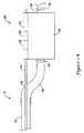
図2Aに医療器具展開システム20の一実施形態を示す。このシステム20においては、駆動要素14がガイド部材12の管腔、及び偏倚連結領域30に形成された開口38を経て格納要素又はその近傍に形成された開口22に入る。駆動要素14は、ガイド部材管腔から格納要素まで、ガイド部材管腔の延長線上をほぼ直線状に延びる。フィルタ、ステント、捕捉器具等の医療器具(図示しない)は、中間の偏倚連結領域30及び介在カップリング等のコンポーネントによりガイド部材12に連結された支持セグメント26のまわりに配置される。以下の記載においてはフィルタの展開に関して主に述べるが、他の器具も同様に搬送及び展開可能であることに留意されたい。支持セグメント26は医療器具内を通過して配置されるか、もしくは医療器具の近傍に配置される。いくつかの実施形態においては、支持セグメント26は医療器具よりも若干長く、展開された医療器具が、支持セグメント26の一部を中心に回転可動、もしくは支持セグメント26の一部に沿って平行移動可能であるように構成される。このような実施形態においては、支持セグメント26が先端側停止部16及び基端側停止部16を有し、これらの停止部により医療器具を支持セグメント26の所望の領域内に留めることができる。 FIG. 2A illustrates one embodiment of a medical
他の実施形態においては、展開された状態の医療器具は、支持セグメントから完全に解放されていてもよいし、支持セグメント26に固着されたままであってもよい。図2A及び2Bの実施形態においては、偏倚連結領域30は独立した要素であり、ガイド部材12を受容する基端側管腔、及び支持セグメント26を受容する先端側管腔を有する。他の実施形態においては、偏倚連結領域30及び支持セグメント26の一方もしくは両方をガイド部材と一体に形成してもよいし、ガイド部材12の延長として形成してもよい。偏倚連結領域30は、ガイド部材12及び支持セグメント26に連通する貫通管腔を有していてもよい。いくつかの実施形態においては、ガイド部材12、偏倚連結領域30、支持セグメント26、及び駆動要素14はほぼ同一平面上に配置される。他の実施形態においては、ガイド部材12、支持セグメント26、及び駆動要素14がほぼ平行に配置される。さらに別の実施形態においては、ガイド部材の軸と支持セグメントの軸とが互いに交差する方向に延びた場合に支持セグメント26の軸が駆動要素14の軸に対して鋭角をなすよう配置される。角度が付けられた支持セグメント26の例を図2Bに示す。 In other embodiments, the deployed medical device may be completely released from the support segment or may remain secured to the
第1の位置にある駆動要素14が格納要素24に対して係合する方法の一例を図3A及び3Bに示す。格納要素24の端部に沿って形成された偏倚フラップ22A及び22Bを折り返すことにより交互するループを形成し、そのループ内に駆動要素14を通過させることができる。 An example of how the
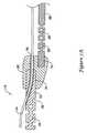
図4においては、駆動要素14を第1の位置から第2の位置へ後退させることによりフラップ22が形成するループから駆動要素14が外され、その結果フィルタ40が格納要素24から出て展開している。格納要素24がその半分同士を連結する線に沿って解放されると、図示するようにフィルタが拡張可能となる。いくつかの実施形態においては、フィルタ40が外側に付勢されたストラット(図示しない)を有し、格納要素24から解放されるとこのストラットによりフィルタ40が拡張する。 In FIG. 4, the
図5A及び5Bに示す実施形態は図2A及び2Bの実施形態によく似ているが、偏倚連結領域30及び支持セグメント26が独立した部材ではなくガイド部材12の先端部から形成されており、支持セグメント26が医療器具の近傍に配置され、格納要素24に接触している場合もある点において異なる。 The embodiment shown in FIGS. 5A and 5B is very similar to the embodiment of FIGS. 2A and 2B, except that the
図6に示す実施形態は、偏倚連結領域30及び支持セグメント26が独立した部材ではなくガイド部材12の先端部から形成されているさらに別の例である。この実施形態においては、格納要素24に対する駆動要素14の係合が縫い目状となっており、格納要素24の折り返された端部に沿って形成された開口を駆動要素14が交互に出入りしている。これにより空隙が埋められ、駆動要素14が第1の位置にあるときに格納状態がもたらされる。 The embodiment shown in FIG. 6 is still another example in which the
図7A〜7Cに、偏倚連結領域30として機能し得る他の構成をいくつか示す。図7Aの実施形態においては、ガイド部材12及び支持セグメント26の両方に、偏倚連結領域30に近い部分において部分的レリーフが施されているため、その領域にさらなる可撓性が付与されている。そして、これにより展開箇所までの医療器具展開システムの移動がよりスムーズになる。この部分的レリーフは、一連の穴、スロット、又は溝28等により施し得る。図7Aに示す実施形態は、金属、プラスチック、又は充填ポリマー等の複合材料から、型成形、鋳造、もしくは機械加工により形成された偏倚連結領域30を含む。図に示すように、偏倚連結領域30は、支持セグメント26を受容する管腔32とガイド部材12を受容する管腔34とを個別に有する。さらに、駆動要素14が管腔開口38を自在に通過できるようになっている。この図においては、駆動要素14は、偏倚連結領域30から基端側すぐの箇所において中実のガイド部材12内に進入している。図7Bに示す偏倚連結領域30も、金属、プラスチック、又は充填ポリマー等の複合材料から、型成形、鋳造、もしくは機械加工により形成可能である。この偏倚連結領域30も、支持セグメント26を受容する管腔32とガイド部材12を受容する管腔34とを個別に有し、さらに、駆動要素14が管腔開口38を自在に通過できるようになっている。図7Cに示す実施形態においては、管状支持セグメント26の基端36が、偏倚連結領域30に挿入される前に圧着されている。この実施形態においては、駆動要素14がガイド部材12の管腔の軸から延びる線に沿ってほぼ直線状に開口38から出ることができ、かつ、支持セグメント26の比較的近くに支持セグメント26と平行して駆動要素を配置することができる。このような構成は、例えば、格納要素24が支持セグメント26に装着され、駆動要素14と格納要素24との係合が支持セグメント26に近接する場合等に好適である。偏倚連結領域、支持セグメント、格納要素、駆動要素、及び医療器具の配置及び構成においては、他の配置及び構成も当業者にとって自明となるであろう。 7A-7C show some other configurations that can function as the
いくつかの実施形態においては支持セグメントがガイド部材に対してほぼ平行かつ偏倚した位置に配置されるが、他の実施形態においては、ガイド部材の延長線に近づく方向又は遠のく方向に傾いて配置される。他の実施形態においては、支持セグメントの大部分がガイド部材の先端より先端側に配置される。いくつかの実施形態においては、偏倚連結領域は、ガイド部材の先端及び偏倚連結領域の基端のいずれかもしくは両方を収容するシースや、偏倚連結領域の先端及び支持セグメントの基端のいずれかもしくは両方を収容するシース等の介在部材を介さずに、ガイド部材と支持セグメントとを連結させる。ガイド部材及び支持セグメントに対する偏倚連結領域の連結は、いくつかの類似する方法にて可能であり、図において便宜上示される共線的な連結例から逸脱する場合もあることは自明である。いくつかの実施形態においては、偏倚連結領域が、金属、ポリマー、又は強化ポリマー等により形成された独立した連結要素を含むが、他の実施形態においては、偏倚連結領域の少なくとも一部が、ガイド部材及び支持セグメントのいずれかもしくは両方から形成される。 In some embodiments, the support segment is disposed at a position that is substantially parallel and offset with respect to the guide member, while in other embodiments, the support segment is disposed in a direction that approaches or extends away from the extension line of the guide member. The In other embodiments, the majority of the support segment is located distal to the distal end of the guide member. In some embodiments, the biasing connection region is a sheath that houses either or both of the distal end of the guide member and the proximal end of the biasing connection region, or either the distal end of the biasing connection region and the proximal end of the support segment, or The guide member and the support segment are connected without using an intervening member such as a sheath that accommodates both. It is self-evident that the connection of the biased connection region to the guide member and the support segment is possible in several similar ways and may deviate from the collinear connection example shown for convenience in the figures. In some embodiments, the biased coupling region includes independent coupling elements formed of metal, polymer, reinforced polymer or the like, while in other embodiments, at least a portion of the biased coupling region is a guide. It is formed from either or both of the member and the support segment.
連結要素又は連結領域を独立して設ける実施形態においては、偏倚連結領域に、ガイド部材を受容する第1の管腔、及び支持セグメントを受容する第2の管腔を設ける場合が多い。いくつかの図に示す連続的な構成以外の別の構成においても、駆動要素がガイド部材から直線状に出て、ガイド部材から同軸上に延びる線に沿って格納要素に対して係合可能であるように各要素を連結できることは自明である。また、駆動要素が専用の開口を要さずに直接ガイド部材から出ることができるように、偏倚連結領域をガイド部材の先端近くに配置してもよい。いくつかの実施形態においては、ガイド部材及び支持セグメントの間の偏倚連結領域が、駆動要素にほぼ一致するとともに長尺状ガイド部材の先端内を通る軸を中心に回転する。ガイド部材、偏倚連結領域、支持セグメント、及び介在要素は、接着剤、半田付け、溶接、かしめ等の手段により連結可能である。また、ガイド部材及び支持セグメントの偏倚連結領域に受容される部分の断面積を縮小してもよい。いくつかの実施形態においては、偏倚連結領域が1つ又は複数のテーパー区画を含む。 In embodiments in which the connecting element or connecting region is provided independently, the biased connecting region is often provided with a first lumen that receives the guide member and a second lumen that receives the support segment. In other configurations than the continuous configuration shown in some of the figures, the drive element can be linearly extended from the guide member and engageable with the storage element along a line extending coaxially from the guide member. It is obvious that each element can be connected in the same way. Further, the bias connection region may be disposed near the tip of the guide member so that the drive element can directly come out of the guide member without requiring a dedicated opening. In some embodiments, the biased connection region between the guide member and the support segment rotates about an axis that substantially coincides with the drive element and passes through the tip of the elongate guide member. The guide member, the bias connection region, the support segment, and the intervening element can be connected by means such as adhesive, soldering, welding, caulking, or the like. Moreover, you may reduce the cross-sectional area of the part received by the biasing connection area | region of a guide member and a support segment. In some embodiments, the biased connection region includes one or more tapered sections.
いくつか実施形態においては、ガイド部材に付随する管腔の軸方向の延長線にほぼ整合する開口が偏倚連結領域に形成され、駆動要素がこれらの管腔及び開口を一本の直線に沿って通過できるようになっている。管腔及び開口を通過した駆動要素は、同一の直線上を格納要素に対する係合箇所まで進み、第1の位置に配置される。いくつかの実施形態においては、偏倚連結領域がガイド部材の二重に湾曲した部分として形成され、支持セグメントがガイド部材のさらに先端側の部分として形成される。さらに別の実施形態においては、医療器具の、支持セグメントに沿った動きが例えば基端側停止部及び/又は先端側停止部により長手方向において制限される。また、ガイド部材に対する支持セグメントの偏倚も、医療器具の基端方向への水平移動を制限する基端側停止機構として機能する。 In some embodiments, openings are formed in the biased coupling region that substantially align with the axial extension of the lumen associated with the guide member, and the drive element extends these lumens and openings along a single straight line. It can be passed. The drive element that has passed through the lumen and the opening travels to the point of engagement with the storage element on the same straight line, and is disposed at the first position. In some embodiments, the biased connection region is formed as a doubly curved portion of the guide member and the support segment is formed as a further distal portion of the guide member. In yet another embodiment, the movement of the medical device along the support segment is restricted in the longitudinal direction, for example by a proximal stop and / or a distal stop. Further, the deviation of the support segment with respect to the guide member also functions as a proximal-side stop mechanism that restricts horizontal movement of the medical device in the proximal direction.
いくつかの実施形態においては、ガイド部材の基端において駆動要素がガイド部材から出る。他の実施形態においては、駆動要素の少なくとも一部分がガイド部材の管腔内に配置され、ガイド部材より先端側に偏倚連結領域内を延びる。さらに別の実施形態においては、シングル・オペレータ・エクスチェンジ型カテーテルのように、駆動要素が、ガイド部材の先端近くにおいてガイド部材に入り、ガイド部材より先端側に偏倚連結領域内を延びる。 In some embodiments, the drive element exits the guide member at the proximal end of the guide member. In other embodiments, at least a portion of the drive element is disposed within the lumen of the guide member and extends within the biased coupling region distal to the guide member. In yet another embodiment, like a single operator exchange catheter, the drive element enters the guide member near the distal end of the guide member and extends in the biased coupling region distal to the guide member.
いくつかの実施形態においては、駆動要素が第1の位置にあるときに、格納要素が医療器具及び支持セグメントの少なくとも一方を少なくとも部分的に覆う。ある実施形態においては、格納要素に1つ又は複数の開口が形成され、第1の位置にある駆動要素は格納要素の1つ又は複数の開口に対して係合し、第2の位置にある駆動要素は格納要素の1つ又は複数の開口の少なくとも大部分に対して非係合状態となる。単純な格納に加えて、格納要素は、駆動要素が第1の位置にあるときに、医療器具に拘束力をもたらすように構成することもできる。駆動要素が第1の位置から第2の位置へ移動されると、格納及び/又は拘束力が除去又は停止される。駆動要素の第1の位置から第2の位置への移動は、駆動要素と格納要素との係合箇所の構成に応じて、駆動要素の基端側又は先端側への移動によりもたらされ得る。他の実施形態においては、駆動要素の第1の位置から第2の位置への移動は、駆動要素の回転によりもたらされる。さらには、水平移動と回転の組み合わせによりもたらされてもよい。 In some embodiments, the storage element at least partially covers at least one of the medical device and the support segment when the drive element is in the first position. In certain embodiments, one or more openings are formed in the storage element, and the drive element in the first position engages with the one or more openings in the storage element and is in the second position. The drive element is disengaged from at least a majority of the one or more openings of the storage element. In addition to simple storage, the storage element can also be configured to provide a restraining force on the medical device when the drive element is in the first position. When the drive element is moved from the first position to the second position, the retracting and / or restraining force is removed or stopped. Movement of the drive element from the first position to the second position can be effected by movement of the drive element to the proximal side or the distal side, depending on the configuration of the engagement point between the drive element and the storage element. . In other embodiments, the movement of the drive element from the first position to the second position is effected by rotation of the drive element. Furthermore, it may be brought about by a combination of horizontal movement and rotation.
いくつかの実施形態においては、穴、スロット、もしくは部分的又は全面的な溝を配することによりガイド部材及び/又は支持セグメントにレリーフを配し、特に偏倚連結領域に近い部分においてガイド部材及び/又は支持セグメントの可撓性を高めるようにしてもよい。このようなレリーフにより、医療装置が展開される箇所へガイド部材及び支持セグメントが搬送される際に、レリーフされた領域が滑らかな移行カーブを保つことが可能となる。穴、スロット及び溝の間隔は、搬送システムに沿って所望の可撓性をもたらすべく、均一であってもよいし、不均一であってもよい。ガイド部材又は支持セグメントはその全長にわたって中実であっても中空であってもよく、また別の実施形態においては、ガイド部材及び支持セグメントのいずれか又は両方の一部が中実又は中空であってもよい。例えばいくつかの実施形態においては、ガイド部材が、偏倚連結領域の基端近くに管腔を有し、駆動部材の一部がその管腔内に配置される。駆動部材は、偏倚連結領域より基端側からガイド部材を出てもよい。 In some embodiments, relief is provided in the guide member and / or support segment by providing a hole, slot, or partial or full groove, particularly in a portion near the biased connection region and / or Alternatively, the flexibility of the support segment may be increased. Such relief allows the relief area to maintain a smooth transition curve when the guide member and support segment are transported to the location where the medical device is deployed. The spacing of the holes, slots and grooves may be uniform or non-uniform to provide the desired flexibility along the transport system. The guide member or support segment may be solid or hollow over its entire length, and in other embodiments, a portion of either or both of the guide member and support segment is solid or hollow. May be. For example, in some embodiments, the guide member has a lumen near the proximal end of the biased connection region and a portion of the drive member is disposed within the lumen. The drive member may exit the guide member from the base end side with respect to the bias connection region.
本発明の種々の別例が、本発明の範囲及び趣旨から逸脱することなく、当業者に明らかになるであろう。本発明は、前述の例示的実施形態に限定されるものでないことを留意されたい。本明細書において言及される全ての出版物及び特許は、各出版物及び特許を、参照することにより個々に具体的に示して本明細書に組み込むのと同じ程度に、参照することにより本明細書に組み込まれるものとする。 Various alternative embodiments of the invention will be apparent to those skilled in the art without departing from the scope and spirit of the invention. It should be noted that the present invention is not limited to the exemplary embodiments described above. All publications and patents mentioned in this specification are hereby incorporated by reference to the same extent as if each publication and patent was specifically indicated by reference and incorporated herein. Shall be incorporated into the document.
Claims (39)
Translated fromJapanese前記長尺状のガイド部材の先端近傍に取付けられる支持セグメントと、
前記支持セグメントに隣接して配置される医療器具と、
前記医療器具の少なくとも一部のまわりに配置される格納要素と、
基端、先端、第1の位置及び第2の位置を有する駆動要素と、
前記ガイド部材及び支持セグメントの間に位置する偏倚連結領域と、を備え、
前記駆動要素が第1の位置にあるときは駆動要素の先端が格納要素の少なくとも一部に対して係合し、駆動要素が第2の位置にあるときは駆動要素の先端が格納要素に対して少なくとも部分的に非係合状態にあり、
前記駆動要素がガイド部材の先端を越えてガイド部材と同軸上を延び、第1の位置において1つ又は複数の箇所において格納要素に対して係合する医療器具展開システム。An elongate guide member having a proximal end, a distal end, and a lumen at least partially penetrating the guide member;
A support segment attached near the tip of the elongated guide member;
A medical device disposed adjacent to the support segment;
A storage element disposed around at least a portion of the medical device;
A drive element having a proximal end, a distal end, a first position and a second position;
A biased connection region located between the guide member and the support segment,
When the drive element is in the first position, the tip of the drive element engages at least a portion of the storage element, and when the drive element is in the second position, the tip of the drive element is relative to the storage element. Are at least partially disengaged,
A medical device deployment system, wherein the drive element extends coaxially with the guide member beyond the tip of the guide member and engages the storage element at one or more locations in a first position.
前記ガイド部材の先端に装着された偏倚連結領域と、
基端、先端、第1の位置、及び第2の位置を有する駆動要素と、
先端、及び前記偏倚連結領域に装着された基端を有する支持セグメントと、
前記支持セグメントに近接して配置される医療器具と、
前記医療器具の少なくとも一部のまわりに配置された格納要素と、を備え、
前記ガイド部材、支持セグメント、及び駆動要素が同一平面上にあり、
前記駆動要素が第1の位置にあるときは駆動要素の先端が格納要素の少なくとも一部に対して係合し、駆動要素が第2の位置にあるときは駆動要素の先端が格納要素に対して少なくとも部分的に非係合状態にあり、
前記駆動要素がガイド部材の先端を越えてガイド部材と同軸上を延びるとともに第1の位置において1つ又は複数の箇所において格納要素に対して係合する医療器具展開システム。An elongate guide member having a proximal end, a distal end, and an associated lumen;
A biased connection region attached to the tip of the guide member;
A drive element having a proximal end, a distal end, a first position, and a second position;
A support segment having a distal end and a proximal end attached to the biased coupling region;
A medical device disposed proximate to the support segment;
A storage element disposed around at least a portion of the medical device;
The guide member, support segment, and drive element are coplanar;
When the drive element is in the first position, the tip of the drive element engages at least a portion of the storage element, and when the drive element is in the second position, the tip of the drive element is relative to the storage element. Are at least partially disengaged,
A medical device deployment system, wherein the drive element extends coaxially with the guide member beyond the tip of the guide member and engages the storage element at one or more locations in a first position.
Applications Claiming Priority (5)
| Application Number | Priority Date | Filing Date | Title |
|---|---|---|---|
| US12261408P | 2008-12-15 | 2008-12-15 | |
| US61/122,614 | 2008-12-15 | ||
| US12/548,499 | 2009-08-27 | ||
| US12/548,499US20100152711A1 (en) | 2008-12-15 | 2009-08-27 | Offset coupling region |
| PCT/US2009/068031WO2010075075A1 (en) | 2008-12-15 | 2009-12-15 | Offset coupling region |
Publications (1)
| Publication Number | Publication Date |
|---|---|
| JP2012512671Atrue JP2012512671A (en) | 2012-06-07 |
Family
ID=42241431
Family Applications (1)
| Application Number | Title | Priority Date | Filing Date |
|---|---|---|---|
| JP2011540969APendingJP2012512671A (en) | 2008-12-15 | 2009-12-15 | Unbalanced connection area |
Country Status (4)
| Country | Link |
|---|---|
| US (1) | US20100152711A1 (en) |
| EP (1) | EP2376022B1 (en) |
| JP (1) | JP2012512671A (en) |
| WO (1) | WO2010075075A1 (en) |
Cited By (2)
| Publication number | Priority date | Publication date | Assignee | Title |
|---|---|---|---|---|
| JP2016524932A (en)* | 2013-06-20 | 2016-08-22 | ヨーテック・ゲゼルシャフト・ミット・ベシュレンクテル・ハフツングJOTEC GmbH | Stent graft |
| JP2019528124A (en)* | 2016-08-24 | 2019-10-10 | ダブリュ.エル.ゴア アンド アソシエイツ,インコーポレイティドW.L. Gore & Associates, Incorporated | Sleeve for expandable medical devices |
Families Citing this family (2)
| Publication number | Priority date | Publication date | Assignee | Title |
|---|---|---|---|---|
| DE202012104446U1 (en) | 2012-11-19 | 2013-01-16 | Till Apfel | Modular plug system |
| US10105519B2 (en)* | 2015-10-20 | 2018-10-23 | C.R. Bard, Inc. | Variable diameter medical balloon |
Family Cites Families (97)
| Publication number | Priority date | Publication date | Assignee | Title |
|---|---|---|---|---|
| US3952747A (en)* | 1974-03-28 | 1976-04-27 | Kimmell Jr Garman O | Filter and filter insertion instrument |
| US4425908A (en)* | 1981-10-22 | 1984-01-17 | Beth Israel Hospital | Blood clot filter |
| US4447227A (en)* | 1982-06-09 | 1984-05-08 | Endoscopy Surgical Systems, Inc. | Multi-purpose medical devices |
| US4643184A (en)* | 1982-09-29 | 1987-02-17 | Mobin Uddin Kazi | Embolus trap |
| US5190546A (en)* | 1983-10-14 | 1993-03-02 | Raychem Corporation | Medical devices incorporating SIM alloy elements |
| US5104399A (en)* | 1986-12-10 | 1992-04-14 | Endovascular Technologies, Inc. | Artificial graft and implantation method |
| US4590938A (en)* | 1984-05-04 | 1986-05-27 | Segura Joseph W | Medical retriever device |
| US5007896A (en)* | 1988-12-19 | 1991-04-16 | Surgical Systems & Instruments, Inc. | Rotary-catheter for atherectomy |
| US4580568A (en)* | 1984-10-01 | 1986-04-08 | Cook, Incorporated | Percutaneous endovascular stent and method for insertion thereof |
| US4807626A (en)* | 1985-02-14 | 1989-02-28 | Mcgirr Douglas B | Stone extractor and method |
| US4650466A (en)* | 1985-11-01 | 1987-03-17 | Angiobrade Partners | Angioplasty device |
| US4733665C2 (en)* | 1985-11-07 | 2002-01-29 | Expandable Grafts Partnership | Expandable intraluminal graft and method and apparatus for implanting an expandable intraluminal graft |
| US4794931A (en)* | 1986-02-28 | 1989-01-03 | Cardiovascular Imaging Systems, Inc. | Catheter apparatus, system and method for intravascular two-dimensional ultrasonography |
| US4728319A (en)* | 1986-03-20 | 1988-03-01 | Helmut Masch | Intravascular catheter |
| US4723549A (en)* | 1986-09-18 | 1988-02-09 | Wholey Mark H | Method and apparatus for dilating blood vessels |
| US4907336A (en)* | 1987-03-13 | 1990-03-13 | Cook Incorporated | Method of making an endovascular stent and delivery system |
| US4800882A (en)* | 1987-03-13 | 1989-01-31 | Cook Incorporated | Endovascular stent and delivery system |
| US4794928A (en)* | 1987-06-10 | 1989-01-03 | Kletschka Harold D | Angioplasty device and method of using the same |
| US5059211A (en)* | 1987-06-25 | 1991-10-22 | Duke University | Absorbable vascular stent |
| US4898575A (en)* | 1987-08-31 | 1990-02-06 | Medinnovations, Inc. | Guide wire following tunneling catheter system and method for transluminal arterial atherectomy |
| FR2624747A1 (en)* | 1987-12-18 | 1989-06-23 | Delsanti Gerard | REMOVABLE ENDO-ARTERIAL DEVICES FOR REPAIRING ARTERIAL WALL DECOLLEMENTS |
| US4896807A (en)* | 1988-04-15 | 1990-01-30 | Quad/Tech, Inc. | Web guide apparatus |
| US5011488A (en)* | 1988-12-07 | 1991-04-30 | Robert Ginsburg | Thrombus extraction system |
| US5087265A (en)* | 1989-02-17 | 1992-02-11 | American Biomed, Inc. | Distal atherectomy catheter |
| DE8910603U1 (en)* | 1989-09-06 | 1989-12-07 | Günther, Rolf W., Prof. Dr. | Device for removing blood clots from arteries and veins |
| US5002560A (en)* | 1989-09-08 | 1991-03-26 | Advanced Cardiovascular Systems, Inc. | Expandable cage catheter with a rotatable guide |
| US5100425A (en)* | 1989-09-14 | 1992-03-31 | Medintec R&D Limited Partnership | Expandable transluminal atherectomy catheter system and method for the treatment of arterial stenoses |
| US5085662A (en)* | 1989-11-13 | 1992-02-04 | Scimed Life Systems, Inc. | Atherectomy catheter and related components |
| US5195955A (en)* | 1989-11-14 | 1993-03-23 | Don Michael T Anthony | Device for removal of embolic debris |
| US5007917A (en)* | 1990-03-08 | 1991-04-16 | Stryker Corporation | Single blade cutter for arthroscopic surgery |
| US5095915A (en)* | 1990-03-19 | 1992-03-17 | Target Therapeutics | Guidewire with flexible distal tip |
| US5100424A (en)* | 1990-05-21 | 1992-03-31 | Cardiovascular Imaging Systems, Inc. | Intravascular catheter having combined imaging abrasion head |
| US5108419A (en)* | 1990-08-16 | 1992-04-28 | Evi Corporation | Endovascular filter and method for use thereof |
| US5100423A (en)* | 1990-08-21 | 1992-03-31 | Medical Engineering & Development Institute, Inc. | Ablation catheter |
| US5409484A (en)* | 1990-09-24 | 1995-04-25 | Erlich; Frederick | Cautery with smoke removal apparatus |
| US5387235A (en)* | 1991-10-25 | 1995-02-07 | Cook Incorporated | Expandable transluminal graft prosthesis for repair of aneurysm |
| FR2683449A1 (en)* | 1991-11-08 | 1993-05-14 | Cardon Alain | ENDOPROTHESIS FOR TRANSLUMINAL IMPLANTATION. |
| US5395349A (en)* | 1991-12-13 | 1995-03-07 | Endovascular Technologies, Inc. | Dual valve reinforced sheath and method |
| US5507767A (en)* | 1992-01-15 | 1996-04-16 | Cook Incorporated | Spiral stent |
| US5405377A (en)* | 1992-02-21 | 1995-04-11 | Endotech Ltd. | Intraluminal stent |
| FR2688401B1 (en)* | 1992-03-12 | 1998-02-27 | Thierry Richard | EXPANDABLE STENT FOR HUMAN OR ANIMAL TUBULAR MEMBER, AND IMPLEMENTATION TOOL. |
| US5405378A (en)* | 1992-05-20 | 1995-04-11 | Strecker; Ernst P. | Device with a prosthesis implantable in the body of a patient |
| US5490859A (en)* | 1992-11-13 | 1996-02-13 | Scimed Life Systems, Inc. | Expandable intravascular occlusion material removal devices and methods of use |
| US5383926A (en)* | 1992-11-23 | 1995-01-24 | Children's Medical Center Corporation | Re-expandable endoprosthesis |
| FR2699809B1 (en)* | 1992-12-28 | 1995-02-17 | Celsa Lg | Device which can selectively constitute a temporary blood filter. |
| EP0609020B1 (en)* | 1993-01-28 | 1998-03-18 | Cook Incorporated | Retention means for catheter |
| EP0749333A1 (en)* | 1994-03-10 | 1996-12-27 | Schneider (Usa) Inc. | Catheter having shaft of varying stiffness |
| FR2718345B1 (en)* | 1994-04-11 | 1997-04-04 | Braun Celsa Sa | Handle for controlled relative sliding of a sheath and a rod and apparatus for implanting a medical device, such as a filter, using such a handle. |
| DE9409484U1 (en)* | 1994-06-11 | 1994-08-04 | Naderlinger, Eduard, 50127 Bergheim | Vena cava thrombus filter |
| US5497785A (en)* | 1994-07-27 | 1996-03-12 | Cordis Corporation | Catheter advancing guidewire and method for making same |
| US6015429A (en)* | 1994-09-08 | 2000-01-18 | Gore Enterprise Holdings, Inc. | Procedures for introducing stents and stent-grafts |
| US5512044A (en)* | 1994-10-11 | 1996-04-30 | Duer; Edward Y. | Embolic cutting catheter |
| US5709704A (en)* | 1994-11-30 | 1998-01-20 | Boston Scientific Corporation | Blood clot filtering |
| CA2212084C (en)* | 1995-02-02 | 2008-11-18 | Boston Scientific Corporation | Surgical wire basket extractor |
| US6168604B1 (en)* | 1995-10-06 | 2001-01-02 | Metamorphic Surgical Devices, Llc | Guide wire device for removing solid objects from body canals |
| US5707359A (en)* | 1995-11-14 | 1998-01-13 | Bufalini; Bruno | Expanding trocar assembly |
| US5728066A (en)* | 1995-12-13 | 1998-03-17 | Daneshvar; Yousef | Injection systems and methods |
| US5713949A (en)* | 1996-08-06 | 1998-02-03 | Jayaraman; Swaminathan | Microporous covered stents and method of coating |
| US6022336A (en)* | 1996-05-20 | 2000-02-08 | Percusurge, Inc. | Catheter system for emboli containment |
| US6068623A (en)* | 1997-03-06 | 2000-05-30 | Percusurge, Inc. | Hollow medical wires and methods of constructing same |
| US5662671A (en)* | 1996-07-17 | 1997-09-02 | Embol-X, Inc. | Atherectomy device having trapping and excising means for removal of plaque from the aorta and other arteries |
| US5893867A (en)* | 1996-11-06 | 1999-04-13 | Percusurge, Inc. | Stent positioning apparatus and method |
| US5876367A (en)* | 1996-12-05 | 1999-03-02 | Embol-X, Inc. | Cerebral protection during carotid endarterectomy and downstream vascular protection during other surgeries |
| US6352561B1 (en)* | 1996-12-23 | 2002-03-05 | W. L. Gore & Associates | Implant deployment apparatus |
| US5814064A (en)* | 1997-03-06 | 1998-09-29 | Scimed Life Systems, Inc. | Distal protection device |
| US5846260A (en)* | 1997-05-08 | 1998-12-08 | Embol-X, Inc. | Cannula with a modular filter for filtering embolic material |
| US5911734A (en)* | 1997-05-08 | 1999-06-15 | Embol-X, Inc. | Percutaneous catheter and guidewire having filter and medical device deployment capabilities |
| US6361545B1 (en)* | 1997-09-26 | 2002-03-26 | Cardeon Corporation | Perfusion filter catheter |
| US6174318B1 (en)* | 1998-04-23 | 2001-01-16 | Scimed Life Systems, Inc. | Basket with one or more moveable legs |
| US6048338A (en)* | 1997-10-15 | 2000-04-11 | Scimed Life Systems, Inc. | Catheter with spiral cut transition member |
| FR2772592B1 (en)* | 1997-12-19 | 2000-04-07 | Braun Celsa Sa | ASSEMBLY FOR THE PLACEMENT OF AN IMPLANT IN AN INTERNAL CONDUIT OF A BODY |
| WO1999039648A1 (en)* | 1998-02-10 | 1999-08-12 | Dubrul William R | Entrapping apparatus and method for use |
| US6206868B1 (en)* | 1998-03-13 | 2001-03-27 | Arteria Medical Science, Inc. | Protective device and method against embolization during treatment of carotid artery disease |
| US6179860B1 (en)* | 1998-08-19 | 2001-01-30 | Artemis Medical, Inc. | Target tissue localization device and method |
| US6051014A (en)* | 1998-10-13 | 2000-04-18 | Embol-X, Inc. | Percutaneous filtration catheter for valve repair surgery and methods of use |
| US6171327B1 (en)* | 1999-02-24 | 2001-01-09 | Scimed Life Systems, Inc. | Intravascular filter and method |
| US6355051B1 (en)* | 1999-03-04 | 2002-03-12 | Bioguide Consulting, Inc. | Guidewire filter device |
| US6277138B1 (en)* | 1999-08-17 | 2001-08-21 | Scion Cardio-Vascular, Inc. | Filter for embolic material mounted on expandable frame |
| US6179859B1 (en)* | 1999-07-16 | 2001-01-30 | Baff Llc | Emboli filtration system and methods of use |
| US6203561B1 (en)* | 1999-07-30 | 2001-03-20 | Incept Llc | Integrated vascular device having thrombectomy element and vascular filter and methods of use |
| US6179861B1 (en)* | 1999-07-30 | 2001-01-30 | Incept Llc | Vascular device having one or more articulation regions and methods of use |
| US6214026B1 (en)* | 1999-07-30 | 2001-04-10 | Incept Llc | Delivery system for a vascular device with articulation region |
| US6168579B1 (en)* | 1999-08-04 | 2001-01-02 | Scimed Life Systems, Inc. | Filter flush system and methods of use |
| US6171328B1 (en)* | 1999-11-09 | 2001-01-09 | Embol-X, Inc. | Intravascular catheter filter with interlocking petal design and methods of use |
| GB2369575A (en)* | 2000-04-20 | 2002-06-05 | Salviac Ltd | An embolic protection system |
| EP1328671B1 (en)* | 2000-10-28 | 2005-07-06 | Saurer GmbH & Co. KG | False twist texturing machine |
| US6537295B2 (en)* | 2001-03-06 | 2003-03-25 | Scimed Life Systems, Inc. | Wire and lock mechanism |
| US6962598B2 (en)* | 2001-07-02 | 2005-11-08 | Rubicon Medical, Inc. | Methods, systems, and devices for providing embolic protection |
| US6951570B2 (en)* | 2001-07-02 | 2005-10-04 | Rubicon Medical, Inc. | Methods, systems, and devices for deploying a filter from a filter device |
| US6878153B2 (en)* | 2001-07-02 | 2005-04-12 | Rubicon Medical, Inc. | Methods, systems, and devices for providing embolic protection and removing embolic material |
| US6997939B2 (en)* | 2001-07-02 | 2006-02-14 | Rubicon Medical, Inc. | Methods, systems, and devices for deploying an embolic protection filter |
| EP1441666B1 (en)* | 2001-11-09 | 2008-01-23 | Rubicon Medical, Inc. | Stent delivery device with embolic protection |
| DE60315425T2 (en)* | 2002-03-05 | 2008-06-26 | Salviac Ltd. | SYSTEM FOR PROTECTION FROM EMBOLICS |
| US7198636B2 (en)* | 2003-01-17 | 2007-04-03 | Gore Enterprise Holdings, Inc. | Deployment system for an endoluminal device |
| US7740644B2 (en)* | 2003-02-24 | 2010-06-22 | Boston Scientific Scimed, Inc. | Embolic protection filtering device that can be adapted to be advanced over a guidewire |
| US9254213B2 (en)* | 2004-01-09 | 2016-02-09 | Rubicon Medical, Inc. | Stent delivery device |
| EP1926453B1 (en)* | 2005-09-19 | 2010-11-17 | Minvasys | Catheter for Placement of a Stent |
- 2009
- 2009-08-27USUS12/548,499patent/US20100152711A1/ennot_activeAbandoned
- 2009-12-15WOPCT/US2009/068031patent/WO2010075075A1/enactiveApplication Filing
- 2009-12-15EPEP09796191Apatent/EP2376022B1/ennot_activeNot-in-force
- 2009-12-15JPJP2011540969Apatent/JP2012512671A/enactivePending
Cited By (5)
| Publication number | Priority date | Publication date | Assignee | Title |
|---|---|---|---|---|
| JP2016524932A (en)* | 2013-06-20 | 2016-08-22 | ヨーテック・ゲゼルシャフト・ミット・ベシュレンクテル・ハフツングJOTEC GmbH | Stent graft |
| JP2019528124A (en)* | 2016-08-24 | 2019-10-10 | ダブリュ.エル.ゴア アンド アソシエイツ,インコーポレイティドW.L. Gore & Associates, Incorporated | Sleeve for expandable medical devices |
| JP2021045581A (en)* | 2016-08-24 | 2021-03-25 | ダブリュ.エル.ゴア アンド アソシエイツ,インコーポレイティドW.L. Gore & Associates, Incorporated | Sleeve for dilated medical devices |
| JP7074829B2 (en) | 2016-08-24 | 2022-05-24 | ダブリュ.エル.ゴア アンド アソシエイツ,インコーポレイティド | Sleeve for extended medical devices |
| US11877942B2 (en) | 2016-08-24 | 2024-01-23 | W. L. Gore & Associates, Inc. | Sleeves for expandable medical devices |
Also Published As
| Publication number | Publication date |
|---|---|
| WO2010075075A1 (en) | 2010-07-01 |
| EP2376022B1 (en) | 2013-01-23 |
| US20100152711A1 (en) | 2010-06-17 |
| EP2376022A1 (en) | 2011-10-19 |
Similar Documents
| Publication | Publication Date | Title |
|---|---|---|
| US9254213B2 (en) | Stent delivery device | |
| US11607301B2 (en) | Intravascular blood filters and methods of use | |
| US9993325B2 (en) | Embolic protection systems | |
| US6485501B1 (en) | Vascular filter system with guidewire and capture mechanism | |
| US20090240238A1 (en) | Clot Retrieval Mechanism | |
| EP2925257B1 (en) | Percutaneous transluminal angioplasty device with integral embolic filter | |
| US20040106944A1 (en) | Distal protection device and method | |
| EP2777650B1 (en) | Distal capture device for a self-expanding stent | |
| JP2008539043A (en) | Branch artery filter system | |
| JP2008534139A (en) | An embolic protection filter that can be replaced by one operator | |
| CN112888406A (en) | Delivery system for stents with protruding features | |
| US20220039936A1 (en) | Systems and methods for protecting the cerebral vasculature | |
| JP2012512671A (en) | Unbalanced connection area | |
| CN118267212B (en) | A stent delivery system | |
| HK40054607A (en) | Delivery systems for stents having protruding features |