JP2012511955A - Biocompatible fiber-based device for tissue-guided regeneration - Google Patents
Biocompatible fiber-based device for tissue-guided regenerationDownload PDFInfo
- Publication number
- JP2012511955A JP2012511955AJP2011540777AJP2011540777AJP2012511955AJP 2012511955 AJP2012511955 AJP 2012511955AJP 2011540777 AJP2011540777 AJP 2011540777AJP 2011540777 AJP2011540777 AJP 2011540777AJP 2012511955 AJP2012511955 AJP 2012511955A
- Authority
- JP
- Japan
- Prior art keywords
- implant
- strap
- nonwoven
- extensions
- tissue engineering
- Prior art date
- Legal status (The legal status is an assumption and is not a legal conclusion. Google has not performed a legal analysis and makes no representation as to the accuracy of the status listed.)
- Pending
Links
- 239000000835fiberSubstances0.000titleclaimsdescription88
- 238000011069regeneration methodMethods0.000titledescription2
- 230000008929regenerationEffects0.000title1
- 239000007943implantSubstances0.000claimsabstractdescription221
- 230000008439repair processEffects0.000claimsabstractdescription47
- 210000003903pelvic floorAnatomy0.000claimsabstractdescription36
- 239000004745nonwoven fabricSubstances0.000claimsdescription15
- 238000005520cutting processMethods0.000claimsdescription10
- 238000005304joiningMethods0.000claimsdescription9
- 238000004080punchingMethods0.000claimsdescription9
- 229920001577copolymerPolymers0.000claimsdescription8
- 229920001519homopolymerPolymers0.000claimsdescription8
- RKDVKSZUMVYZHH-UHFFFAOYSA-N1,4-dioxane-2,5-dioneChemical compoundO=C1COC(=O)CO1RKDVKSZUMVYZHH-UHFFFAOYSA-N0.000claimsdescription7
- JJTUDXZGHPGLLC-UHFFFAOYSA-NlactideChemical compoundCC1OC(=O)C(C)OC1=OJJTUDXZGHPGLLC-UHFFFAOYSA-N0.000claimsdescription6
- 239000000178monomerSubstances0.000claimsdescription6
- VPVXHAANQNHFSF-UHFFFAOYSA-N1,4-dioxan-2-oneChemical compoundO=C1COCCO1VPVXHAANQNHFSF-UHFFFAOYSA-N0.000claimsdescription5
- PAPBSGBWRJIAAV-UHFFFAOYSA-Nε-CaprolactoneChemical compoundO=C1CCCCCO1PAPBSGBWRJIAAV-UHFFFAOYSA-N0.000claimsdescription4
- YFHICDDUDORKJB-UHFFFAOYSA-Ntrimethylene carbonateChemical compoundO=C1OCCCO1YFHICDDUDORKJB-UHFFFAOYSA-N0.000claimsdescription2
- 210000001519tissueAnatomy0.000description86
- 210000004027cellAnatomy0.000description32
- 241001465754MetazoaSpecies0.000description27
- 238000000034methodMethods0.000description26
- 239000000463materialSubstances0.000description25
- XLYOFNOQVPJJNP-UHFFFAOYSA-NwaterSubstancesOXLYOFNOQVPJJNP-UHFFFAOYSA-N0.000description19
- 238000004519manufacturing processMethods0.000description17
- 238000012360testing methodMethods0.000description13
- 230000032798delaminationEffects0.000description10
- 210000003195fasciaAnatomy0.000description10
- 108090000623proteins and genesProteins0.000description10
- 108020004707nucleic acidsProteins0.000description9
- 102000039446nucleic acidsHuman genes0.000description9
- 150000007523nucleic acidsChemical class0.000description9
- 229920002463poly(p-dioxanone) polymerPolymers0.000description9
- 239000000622polydioxanoneSubstances0.000description9
- 230000017423tissue regenerationEffects0.000description9
- 230000003612virological effectEffects0.000description9
- WSFSSNUMVMOOMR-UHFFFAOYSA-NFormaldehydeChemical compoundO=CWSFSSNUMVMOOMR-UHFFFAOYSA-N0.000description8
- 239000004744fabricSubstances0.000description8
- 210000001215vaginaAnatomy0.000description8
- 206010002329AneurysmDiseases0.000description7
- 102000008186CollagenHuman genes0.000description7
- 108010035532CollagenProteins0.000description7
- 241000700605VirusesSpecies0.000description7
- 229920001436collagenPolymers0.000description7
- 230000007547defectEffects0.000description7
- 230000006870functionEffects0.000description7
- 239000000203mixtureSubstances0.000description7
- 230000008569processEffects0.000description7
- 210000003491skinAnatomy0.000description7
- 210000000130stem cellAnatomy0.000description7
- 238000001356surgical procedureMethods0.000description7
- 238000010171animal modelMethods0.000description6
- 239000012867bioactive agentSubstances0.000description6
- 210000002808connective tissueAnatomy0.000description6
- 239000002245particleSubstances0.000description6
- -1polyoxaestersPolymers0.000description6
- 102000004169proteins and genesHuman genes0.000description6
- 206010019909HerniaDiseases0.000description5
- 210000003484anatomyAnatomy0.000description5
- 230000006378damageEffects0.000description5
- 239000011148porous materialSubstances0.000description5
- 210000000664rectumAnatomy0.000description5
- 238000011282treatmentMethods0.000description5
- 206010011803CystoceleDiseases0.000description4
- IAYPIBMASNFSPL-UHFFFAOYSA-NEthylene oxideChemical compoundC1CO1IAYPIBMASNFSPL-UHFFFAOYSA-N0.000description4
- WZUVPPKBWHMQCE-UHFFFAOYSA-NHaematoxylinChemical compoundC12=CC(O)=C(O)C=C2CC2(O)C1C1=CC=C(O)C(O)=C1OC2WZUVPPKBWHMQCE-UHFFFAOYSA-N0.000description4
- 230000033228biological regulationEffects0.000description4
- 238000011156evaluationMethods0.000description4
- 210000002950fibroblastAnatomy0.000description4
- 238000002513implantationMethods0.000description4
- 210000003041ligamentAnatomy0.000description4
- 210000003205muscleAnatomy0.000description4
- 238000002360preparation methodMethods0.000description4
- 239000000725suspensionSubstances0.000description4
- 206010002091AnaesthesiaDiseases0.000description3
- 238000010162Tukey testMethods0.000description3
- 230000037005anaesthesiaEffects0.000description3
- 229940088710antibiotic agentDrugs0.000description3
- 230000004888barrier functionEffects0.000description3
- 210000001612chondrocyteAnatomy0.000description3
- 238000009472formulationMethods0.000description3
- 230000014509gene expressionEffects0.000description3
- 239000002609mediumSubstances0.000description3
- 230000004048modificationEffects0.000description3
- 238000012986modificationMethods0.000description3
- 210000004197pelvisAnatomy0.000description3
- 229920000642polymerPolymers0.000description3
- 210000004304subcutaneous tissueAnatomy0.000description3
- 210000002435tendonAnatomy0.000description3
- KIUKXJAPPMFGSW-DNGZLQJQSA-N(2S,3S,4S,5R,6R)-6-[(2S,3R,4R,5S,6R)-3-Acetamido-2-[(2S,3S,4R,5R,6R)-6-[(2R,3R,4R,5S,6R)-3-acetamido-2,5-dihydroxy-6-(hydroxymethyl)oxan-4-yl]oxy-2-carboxy-4,5-dihydroxyoxan-3-yl]oxy-5-hydroxy-6-(hydroxymethyl)oxan-4-yl]oxy-3,4,5-trihydroxyoxane-2-carboxylic acidChemical compoundCC(=O)N[C@H]1[C@H](O)O[C@H](CO)[C@@H](O)[C@@H]1O[C@H]1[C@H](O)[C@@H](O)[C@H](O[C@H]2[C@@H]([C@@H](O[C@H]3[C@@H]([C@@H](O)[C@H](O)[C@H](O3)C(O)=O)O)[C@H](O)[C@@H](CO)O2)NC(C)=O)[C@@H](C(O)=O)O1KIUKXJAPPMFGSW-DNGZLQJQSA-N0.000description2
- RYHBNJHYFVUHQT-UHFFFAOYSA-N1,4-DioxaneChemical compoundC1COCCO1RYHBNJHYFVUHQT-UHFFFAOYSA-N0.000description2
- LCSKNASZPVZHEG-UHFFFAOYSA-N3,6-dimethyl-1,4-dioxane-2,5-dione;1,4-dioxane-2,5-dioneChemical compoundO=C1COC(=O)CO1.CC1OC(=O)C(C)OC1=OLCSKNASZPVZHEG-UHFFFAOYSA-N0.000description2
- UKJOPALDTJXHKX-UHFFFAOYSA-N4-azido-2,3,5,6-tetrafluoropyridineChemical compoundFC1=NC(F)=C(F)C(N=[N+]=[N-])=C1FUKJOPALDTJXHKX-UHFFFAOYSA-N0.000description2
- AEMRFAOFKBGASW-UHFFFAOYSA-NGlycolic acidChemical compoundOCC(O)=OAEMRFAOFKBGASW-UHFFFAOYSA-N0.000description2
- PIWKPBJCKXDKJR-UHFFFAOYSA-NIsofluraneChemical compoundFC(F)OC(Cl)C(F)(F)FPIWKPBJCKXDKJR-UHFFFAOYSA-N0.000description2
- KFZMGEQAYNKOFK-UHFFFAOYSA-NIsopropanolChemical compoundCC(C)OKFZMGEQAYNKOFK-UHFFFAOYSA-N0.000description2
- 241000283973Oryctolagus cuniculusSpecies0.000description2
- 239000004952PolyamideSubstances0.000description2
- 239000004743PolypropyleneSubstances0.000description2
- 208000012287ProlapseDiseases0.000description2
- 206010038084RectoceleDiseases0.000description2
- 208000027418Wounds and injuryDiseases0.000description2
- 210000001015abdomenAnatomy0.000description2
- 229920003232aliphatic polyesterPolymers0.000description2
- 229940035676analgesicsDrugs0.000description2
- 239000000730antalgic agentSubstances0.000description2
- 239000003242anti bacterial agentSubstances0.000description2
- 229920001222biopolymerPolymers0.000description2
- 238000000861blow dryingMethods0.000description2
- 210000002449bone cellAnatomy0.000description2
- 210000002798bone marrow cellAnatomy0.000description2
- 230000015556catabolic processEffects0.000description2
- 230000001413cellular effectEffects0.000description2
- 239000003795chemical substances by applicationSubstances0.000description2
- 238000006731degradation reactionMethods0.000description2
- 241001493065dsRNA virusesSpecies0.000description2
- 230000000694effectsEffects0.000description2
- 229920001971elastomerPolymers0.000description2
- 210000001671embryonic stem cellAnatomy0.000description2
- YQGOJNYOYNNSMM-UHFFFAOYSA-NeosinChemical compound[Na+].OC(=O)C1=CC=CC=C1C1=C2C=C(Br)C(=O)C(Br)=C2OC2=C(Br)C(O)=C(Br)C=C21YQGOJNYOYNNSMM-UHFFFAOYSA-N0.000description2
- 229920006379extruded polypropylenePolymers0.000description2
- 239000006260foamSubstances0.000description2
- 238000002695general anesthesiaMethods0.000description2
- 230000035876healingEffects0.000description2
- 229920002674hyaluronanPolymers0.000description2
- 229960003160hyaluronic acidDrugs0.000description2
- 230000001965increasing effectEffects0.000description2
- 208000015181infectious diseaseDiseases0.000description2
- 208000014674injuryDiseases0.000description2
- 230000000968intestinal effectEffects0.000description2
- 210000000936intestineAnatomy0.000description2
- 229960002725isofluraneDrugs0.000description2
- JVTAAEKCZFNVCJ-UHFFFAOYSA-Nlactic acidChemical compoundCC(O)C(O)=OJVTAAEKCZFNVCJ-UHFFFAOYSA-N0.000description2
- 210000000056organAnatomy0.000description2
- 206010033675panniculitisDiseases0.000description2
- 239000012188paraffin waxSubstances0.000description2
- 210000002640perineumAnatomy0.000description2
- 210000005259peripheral bloodAnatomy0.000description2
- 239000011886peripheral bloodSubstances0.000description2
- 239000004033plasticSubstances0.000description2
- 229920003023plasticPolymers0.000description2
- 229920002647polyamidePolymers0.000description2
- 229920001155polypropylenePolymers0.000description2
- 239000002243precursorSubstances0.000description2
- 108090000765processed proteins & peptidesProteins0.000description2
- 102000004196processed proteins & peptidesHuman genes0.000description2
- 230000001737promoting effectEffects0.000description2
- 230000005180public healthEffects0.000description2
- 210000001139rectus abdominisAnatomy0.000description2
- 230000002829reductive effectEffects0.000description2
- 239000004627regenerated celluloseSubstances0.000description2
- 238000001878scanning electron micrographMethods0.000description2
- 239000000243solutionSubstances0.000description2
- 238000009987spinningMethods0.000description2
- 229910001220stainless steelInorganic materials0.000description2
- 239000010935stainless steelSubstances0.000description2
- 238000005728strengtheningMethods0.000description2
- 210000002536stromal cellAnatomy0.000description2
- 210000002437synoviocyteAnatomy0.000description2
- 239000004753textileSubstances0.000description2
- JJTUDXZGHPGLLC-ZXZARUISSA-N(3r,6s)-3,6-dimethyl-1,4-dioxane-2,5-dioneChemical compoundC[C@H]1OC(=O)[C@H](C)OC1=OJJTUDXZGHPGLLC-ZXZARUISSA-N0.000description1
- UJGHGRGFKZWGMS-UHFFFAOYSA-N1,3-dioxan-2-oneChemical compoundO=C1OCCCO1.O=C1OCCCO1UJGHGRGFKZWGMS-UHFFFAOYSA-N0.000description1
- KKGSHHDRPRINNY-UHFFFAOYSA-N1,4-dioxan-2-oneChemical compoundO=C1COCCO1.O=C1COCCO1KKGSHHDRPRINNY-UHFFFAOYSA-N0.000description1
- CQVWXNBVRLKXPE-UHFFFAOYSA-N2-octyl cyanoacrylateChemical compoundCCCCCCC(C)OC(=O)C(=C)C#NCQVWXNBVRLKXPE-UHFFFAOYSA-N0.000description1
- ZCYVEMRRCGMTRW-UHFFFAOYSA-N7553-56-2Chemical compound[I]ZCYVEMRRCGMTRW-UHFFFAOYSA-N0.000description1
- 229920001651CyanoacrylatePolymers0.000description1
- 102000004127CytokinesHuman genes0.000description1
- 108090000695CytokinesProteins0.000description1
- 208000032767Device breakageDiseases0.000description1
- 239000006144Dulbecco’s modified Eagle's mediumSubstances0.000description1
- 102000016942ElastinHuman genes0.000description1
- 108010014258ElastinProteins0.000description1
- 102000004190EnzymesHuman genes0.000description1
- 108090000790EnzymesProteins0.000description1
- LFQSCWFLJHTTHZ-UHFFFAOYSA-NEthanolChemical compoundCCOLFQSCWFLJHTTHZ-UHFFFAOYSA-N0.000description1
- 102000003886GlycoproteinsHuman genes0.000description1
- 108090000288GlycoproteinsProteins0.000description1
- VPNYRYCIDCJBOM-UHFFFAOYSA-MGlycopyrronium bromideChemical compound[Br-].C1[N+](C)(C)CCC1OC(=O)C(O)(C=1C=CC=CC=1)C1CCCC1VPNYRYCIDCJBOM-UHFFFAOYSA-M0.000description1
- 229920002683GlycosaminoglycanPolymers0.000description1
- 108060003393GranulinProteins0.000description1
- 241000282412HomoSpecies0.000description1
- 206010061218InflammationDiseases0.000description1
- YQEZLKZALYSWHR-UHFFFAOYSA-NKetamineChemical compoundC=1C=CC=C(Cl)C=1C1(NC)CCCCC1=OYQEZLKZALYSWHR-UHFFFAOYSA-N0.000description1
- OUYCCCASQSFEME-QMMMGPOBSA-NL-tyrosineChemical compoundOC(=O)[C@@H](N)CC1=CC=C(O)C=C1OUYCCCASQSFEME-QMMMGPOBSA-N0.000description1
- 108091034117OligonucleotideProteins0.000description1
- 208000034530PLAA-associated neurodevelopmental diseaseDiseases0.000description1
- QGMRQYFBGABWDR-UHFFFAOYSA-MPentobarbital sodiumChemical compound[Na+].CCCC(C)C1(CC)C(=O)NC(=O)[N-]C1=OQGMRQYFBGABWDR-UHFFFAOYSA-M0.000description1
- 229920002732PolyanhydridePolymers0.000description1
- 229920001710PolyorthoesterPolymers0.000description1
- 229920002472StarchPolymers0.000description1
- 241000282887SuidaeSpecies0.000description1
- 241000282898Sus scrofaSpecies0.000description1
- 208000031737Tissue AdhesionsDiseases0.000description1
- 210000003815abdominal wallAnatomy0.000description1
- 230000002745absorbentEffects0.000description1
- 239000002250absorbentSubstances0.000description1
- 230000009471actionEffects0.000description1
- 230000001154acute effectEffects0.000description1
- 239000000853adhesiveSubstances0.000description1
- 230000001070adhesive effectEffects0.000description1
- 210000001789adipocyteAnatomy0.000description1
- 210000000577adipose tissueAnatomy0.000description1
- 230000002411adverseEffects0.000description1
- 125000000217alkyl groupChemical group0.000description1
- 230000000735allogeneic effectEffects0.000description1
- 125000003277amino groupChemical group0.000description1
- 230000000844anti-bacterial effectEffects0.000description1
- 239000002260anti-inflammatory agentSubstances0.000description1
- 229940121363anti-inflammatory agentDrugs0.000description1
- 210000000436anusAnatomy0.000description1
- QVGXLLKOCUKJST-UHFFFAOYSA-Natomic oxygenChemical compound[O]QVGXLLKOCUKJST-UHFFFAOYSA-N0.000description1
- 230000008901benefitEffects0.000description1
- 239000011230binding agentSubstances0.000description1
- 239000000560biocompatible materialSubstances0.000description1
- 229920000249biocompatible polymerPolymers0.000description1
- 230000031018biological processes and functionsEffects0.000description1
- 230000008512biological responseEffects0.000description1
- 230000015572biosynthetic processEffects0.000description1
- 229920001400block copolymerPolymers0.000description1
- 230000000903blocking effectEffects0.000description1
- 210000004204blood vesselAnatomy0.000description1
- 210000001217buttockAnatomy0.000description1
- 238000003490calenderingMethods0.000description1
- 239000013592cell lysateSubstances0.000description1
- 230000003399chemotactic effectEffects0.000description1
- 230000035606childbirthEffects0.000description1
- WDRFFJWBUDTUCA-UHFFFAOYSA-Nchlorhexidine acetateChemical compoundCC(O)=O.CC(O)=O.C=1C=C(Cl)C=CC=1NC(N)=NC(N)=NCCCCCCN=C(N)N=C(N)NC1=CC=C(Cl)C=C1WDRFFJWBUDTUCA-UHFFFAOYSA-N0.000description1
- 229960001884chlorhexidine diacetateDrugs0.000description1
- 150000001875compoundsChemical class0.000description1
- 239000006071creamSubstances0.000description1
- 230000001419dependent effectEffects0.000description1
- 201000010099diseaseDiseases0.000description1
- 208000037265diseases, disorders, signs and symptomsDiseases0.000description1
- 229940079593drugDrugs0.000description1
- 239000003814drugSubstances0.000description1
- 229920002549elastinPolymers0.000description1
- 210000002889endothelial cellAnatomy0.000description1
- 238000005516engineering processMethods0.000description1
- 210000002919epithelial cellAnatomy0.000description1
- 150000002148estersChemical class0.000description1
- 229940011871estrogenDrugs0.000description1
- 239000000262estrogenSubstances0.000description1
- 239000012530fluidSubstances0.000description1
- 239000012634fragmentSubstances0.000description1
- 238000001415gene therapyMethods0.000description1
- 229940015042glycopyrrolateDrugs0.000description1
- PCHJSUWPFVWCPO-UHFFFAOYSA-NgoldChemical compound[Au]PCHJSUWPFVWCPO-UHFFFAOYSA-N0.000description1
- 239000010931goldSubstances0.000description1
- 229910052737goldInorganic materials0.000description1
- 239000003102growth factorSubstances0.000description1
- 210000003630histaminocyteAnatomy0.000description1
- 239000005556hormoneSubstances0.000description1
- 229940088597hormoneDrugs0.000description1
- 210000000987immune systemAnatomy0.000description1
- 229960003444immunosuppressant agentDrugs0.000description1
- 239000003018immunosuppressive agentSubstances0.000description1
- 238000001727in vivoMethods0.000description1
- 230000006698inductionEffects0.000description1
- 230000001939inductive effectEffects0.000description1
- 230000004054inflammatory processEffects0.000description1
- 230000028709inflammatory responseEffects0.000description1
- 238000002347injectionMethods0.000description1
- 239000007924injectionSubstances0.000description1
- 230000010354integrationEffects0.000description1
- 230000002452interceptive effectEffects0.000description1
- 238000010255intramuscular injectionMethods0.000description1
- 239000007927intramuscular injectionSubstances0.000description1
- 238000001990intravenous administrationMethods0.000description1
- 238000010253intravenous injectionMethods0.000description1
- 229910052740iodineInorganic materials0.000description1
- 239000011630iodineSubstances0.000description1
- 229960003299ketamineDrugs0.000description1
- 235000014655lactic acidNutrition0.000description1
- 239000004310lactic acidSubstances0.000description1
- 201000011135lateral cystoceleDiseases0.000description1
- 210000000265leukocyteAnatomy0.000description1
- 230000000670limiting effectEffects0.000description1
- 210000002540macrophageAnatomy0.000description1
- 239000011159matrix materialSubstances0.000description1
- 238000005259measurementMethods0.000description1
- 239000012528membraneSubstances0.000description1
- 244000309715mini pigSpecies0.000description1
- 210000001616monocyteAnatomy0.000description1
- 210000003098myoblastAnatomy0.000description1
- 210000002569neuronAnatomy0.000description1
- 230000007935neutral effectEffects0.000description1
- 238000011587new zealand white rabbitMethods0.000description1
- 230000008520organizationEffects0.000description1
- 210000000963osteoblastAnatomy0.000description1
- 210000002997osteoclastAnatomy0.000description1
- 150000003891oxalate saltsChemical class0.000description1
- 229910052760oxygenInorganic materials0.000description1
- 239000001301oxygenSubstances0.000description1
- 229960002275pentobarbital sodiumDrugs0.000description1
- 210000004180plasmocyteAnatomy0.000description1
- 210000004623platelet-rich plasmaAnatomy0.000description1
- 229920001308poly(aminoacid)Polymers0.000description1
- 229920002469poly(p-dioxane) polymerPolymers0.000description1
- 229920002627poly(phosphazenes)Polymers0.000description1
- 229920001281polyalkylenePolymers0.000description1
- 229920000515polycarbonatePolymers0.000description1
- 239000004417polycarbonateSubstances0.000description1
- 229920001223polyethylene glycolPolymers0.000description1
- 229920001184polypeptidePolymers0.000description1
- 230000003449preventive effectEffects0.000description1
- 238000012545processingMethods0.000description1
- 230000001105regulatory effectEffects0.000description1
- 230000002787reinforcementEffects0.000description1
- 239000012779reinforcing materialSubstances0.000description1
- 238000007634remodelingMethods0.000description1
- 230000004044responseEffects0.000description1
- 238000012552reviewMethods0.000description1
- 229920002477rna polymerPolymers0.000description1
- 238000004626scanning electron microscopyMethods0.000description1
- 241000894007speciesSpecies0.000description1
- 235000019698starchNutrition0.000description1
- 150000003431steroidsChemical class0.000description1
- 239000000126substanceSubstances0.000description1
- 239000000758substrateSubstances0.000description1
- 238000011477surgical interventionMethods0.000description1
- 208000037816tissue injuryDiseases0.000description1
- 230000007838tissue remodelingEffects0.000description1
- 238000009966trimmingMethods0.000description1
- OUYCCCASQSFEME-UHFFFAOYSA-NtyrosineNatural productsOC(=O)C(N)CC1=CC=C(O)C=C1OUYCCCASQSFEME-UHFFFAOYSA-N0.000description1
- 210000004291uterusAnatomy0.000description1
- 239000013603viral vectorSubstances0.000description1
- 229960001600xylazineDrugs0.000description1
- BPICBUSOMSTKRF-UHFFFAOYSA-NxylazineChemical compoundCC1=CC=CC(C)=C1NC1=NCCCS1BPICBUSOMSTKRF-UHFFFAOYSA-N0.000description1
Images


Classifications
- A—HUMAN NECESSITIES
- A61—MEDICAL OR VETERINARY SCIENCE; HYGIENE
- A61F—FILTERS IMPLANTABLE INTO BLOOD VESSELS; PROSTHESES; DEVICES PROVIDING PATENCY TO, OR PREVENTING COLLAPSING OF, TUBULAR STRUCTURES OF THE BODY, e.g. STENTS; ORTHOPAEDIC, NURSING OR CONTRACEPTIVE DEVICES; FOMENTATION; TREATMENT OR PROTECTION OF EYES OR EARS; BANDAGES, DRESSINGS OR ABSORBENT PADS; FIRST-AID KITS
- A61F2/00—Filters implantable into blood vessels; Prostheses, i.e. artificial substitutes or replacements for parts of the body; Appliances for connecting them with the body; Devices providing patency to, or preventing collapsing of, tubular structures of the body, e.g. stents
- A61F2/0004—Closure means for urethra or rectum, i.e. anti-incontinence devices or support slings against pelvic prolapse
- A61F2/0031—Closure means for urethra or rectum, i.e. anti-incontinence devices or support slings against pelvic prolapse for constricting the lumen; Support slings for the urethra
- A61F2/0036—Closure means for urethra or rectum, i.e. anti-incontinence devices or support slings against pelvic prolapse for constricting the lumen; Support slings for the urethra implantable
- A61F2/0045—Support slings
- B—PERFORMING OPERATIONS; TRANSPORTING
- B32—LAYERED PRODUCTS
- B32B—LAYERED PRODUCTS, i.e. PRODUCTS BUILT-UP OF STRATA OF FLAT OR NON-FLAT, e.g. CELLULAR OR HONEYCOMB, FORM
- B32B5/00—Layered products characterised by the non- homogeneity or physical structure, i.e. comprising a fibrous, filamentary, particulate or foam layer; Layered products characterised by having a layer differing constitutionally or physically in different parts
- B32B5/02—Layered products characterised by the non- homogeneity or physical structure, i.e. comprising a fibrous, filamentary, particulate or foam layer; Layered products characterised by having a layer differing constitutionally or physically in different parts characterised by structural features of a fibrous or filamentary layer
- B32B5/022—Non-woven fabric
- B—PERFORMING OPERATIONS; TRANSPORTING
- B32—LAYERED PRODUCTS
- B32B—LAYERED PRODUCTS, i.e. PRODUCTS BUILT-UP OF STRATA OF FLAT OR NON-FLAT, e.g. CELLULAR OR HONEYCOMB, FORM
- B32B5/00—Layered products characterised by the non- homogeneity or physical structure, i.e. comprising a fibrous, filamentary, particulate or foam layer; Layered products characterised by having a layer differing constitutionally or physically in different parts
- B32B5/02—Layered products characterised by the non- homogeneity or physical structure, i.e. comprising a fibrous, filamentary, particulate or foam layer; Layered products characterised by having a layer differing constitutionally or physically in different parts characterised by structural features of a fibrous or filamentary layer
- B32B5/026—Knitted fabric
- B—PERFORMING OPERATIONS; TRANSPORTING
- B32—LAYERED PRODUCTS
- B32B—LAYERED PRODUCTS, i.e. PRODUCTS BUILT-UP OF STRATA OF FLAT OR NON-FLAT, e.g. CELLULAR OR HONEYCOMB, FORM
- B32B5/00—Layered products characterised by the non- homogeneity or physical structure, i.e. comprising a fibrous, filamentary, particulate or foam layer; Layered products characterised by having a layer differing constitutionally or physically in different parts
- B32B5/02—Layered products characterised by the non- homogeneity or physical structure, i.e. comprising a fibrous, filamentary, particulate or foam layer; Layered products characterised by having a layer differing constitutionally or physically in different parts characterised by structural features of a fibrous or filamentary layer
- B32B5/08—Layered products characterised by the non- homogeneity or physical structure, i.e. comprising a fibrous, filamentary, particulate or foam layer; Layered products characterised by having a layer differing constitutionally or physically in different parts characterised by structural features of a fibrous or filamentary layer the fibres or filaments of a layer being of different substances, e.g. conjugate fibres, mixture of different fibres
- B—PERFORMING OPERATIONS; TRANSPORTING
- B32—LAYERED PRODUCTS
- B32B—LAYERED PRODUCTS, i.e. PRODUCTS BUILT-UP OF STRATA OF FLAT OR NON-FLAT, e.g. CELLULAR OR HONEYCOMB, FORM
- B32B5/00—Layered products characterised by the non- homogeneity or physical structure, i.e. comprising a fibrous, filamentary, particulate or foam layer; Layered products characterised by having a layer differing constitutionally or physically in different parts
- B32B5/22—Layered products characterised by the non- homogeneity or physical structure, i.e. comprising a fibrous, filamentary, particulate or foam layer; Layered products characterised by having a layer differing constitutionally or physically in different parts characterised by the presence of two or more layers which are next to each other and are fibrous, filamentary, formed of particles or foamed
- B32B5/24—Layered products characterised by the non- homogeneity or physical structure, i.e. comprising a fibrous, filamentary, particulate or foam layer; Layered products characterised by having a layer differing constitutionally or physically in different parts characterised by the presence of two or more layers which are next to each other and are fibrous, filamentary, formed of particles or foamed one layer being a fibrous or filamentary layer
- B32B5/26—Layered products characterised by the non- homogeneity or physical structure, i.e. comprising a fibrous, filamentary, particulate or foam layer; Layered products characterised by having a layer differing constitutionally or physically in different parts characterised by the presence of two or more layers which are next to each other and are fibrous, filamentary, formed of particles or foamed one layer being a fibrous or filamentary layer another layer next to it also being fibrous or filamentary
- B—PERFORMING OPERATIONS; TRANSPORTING
- B32—LAYERED PRODUCTS
- B32B—LAYERED PRODUCTS, i.e. PRODUCTS BUILT-UP OF STRATA OF FLAT OR NON-FLAT, e.g. CELLULAR OR HONEYCOMB, FORM
- B32B7/00—Layered products characterised by the relation between layers; Layered products characterised by the relative orientation of features between layers, or by the relative values of a measurable parameter between layers, i.e. products comprising layers having different physical, chemical or physicochemical properties; Layered products characterised by the interconnection of layers
- B32B7/04—Interconnection of layers
- B32B7/12—Interconnection of layers using interposed adhesives or interposed materials with bonding properties
- D—TEXTILES; PAPER
- D04—BRAIDING; LACE-MAKING; KNITTING; TRIMMINGS; NON-WOVEN FABRICS
- D04H—MAKING TEXTILE FABRICS, e.g. FROM FIBRES OR FILAMENTARY MATERIAL; FABRICS MADE BY SUCH PROCESSES OR APPARATUS, e.g. FELTS, NON-WOVEN FABRICS; COTTON-WOOL; WADDING ; NON-WOVEN FABRICS FROM STAPLE FIBRES, FILAMENTS OR YARNS, BONDED WITH AT LEAST ONE WEB-LIKE MATERIAL DURING THEIR CONSOLIDATION
- D04H1/00—Non-woven fabrics formed wholly or mainly of staple fibres or like relatively short fibres
- D04H1/40—Non-woven fabrics formed wholly or mainly of staple fibres or like relatively short fibres from fleeces or layers composed of fibres without existing or potential cohesive properties
- D04H1/44—Non-woven fabrics formed wholly or mainly of staple fibres or like relatively short fibres from fleeces or layers composed of fibres without existing or potential cohesive properties the fleeces or layers being consolidated by mechanical means, e.g. by rolling
- D04H1/46—Non-woven fabrics formed wholly or mainly of staple fibres or like relatively short fibres from fleeces or layers composed of fibres without existing or potential cohesive properties the fleeces or layers being consolidated by mechanical means, e.g. by rolling by needling or like operations to cause entanglement of fibres
- D04H1/492—Non-woven fabrics formed wholly or mainly of staple fibres or like relatively short fibres from fleeces or layers composed of fibres without existing or potential cohesive properties the fleeces or layers being consolidated by mechanical means, e.g. by rolling by needling or like operations to cause entanglement of fibres by fluid jet
- D—TEXTILES; PAPER
- D04—BRAIDING; LACE-MAKING; KNITTING; TRIMMINGS; NON-WOVEN FABRICS
- D04H—MAKING TEXTILE FABRICS, e.g. FROM FIBRES OR FILAMENTARY MATERIAL; FABRICS MADE BY SUCH PROCESSES OR APPARATUS, e.g. FELTS, NON-WOVEN FABRICS; COTTON-WOOL; WADDING ; NON-WOVEN FABRICS FROM STAPLE FIBRES, FILAMENTS OR YARNS, BONDED WITH AT LEAST ONE WEB-LIKE MATERIAL DURING THEIR CONSOLIDATION
- D04H3/00—Non-woven fabrics formed wholly or mainly of yarns or like filamentary material of substantial length
- D04H3/08—Non-woven fabrics formed wholly or mainly of yarns or like filamentary material of substantial length characterised by the method of strengthening or consolidating
- D04H3/10—Non-woven fabrics formed wholly or mainly of yarns or like filamentary material of substantial length characterised by the method of strengthening or consolidating with bonds between yarns or filaments made mechanically
- D04H3/11—Non-woven fabrics formed wholly or mainly of yarns or like filamentary material of substantial length characterised by the method of strengthening or consolidating with bonds between yarns or filaments made mechanically by fluid jet
- A—HUMAN NECESSITIES
- A61—MEDICAL OR VETERINARY SCIENCE; HYGIENE
- A61F—FILTERS IMPLANTABLE INTO BLOOD VESSELS; PROSTHESES; DEVICES PROVIDING PATENCY TO, OR PREVENTING COLLAPSING OF, TUBULAR STRUCTURES OF THE BODY, e.g. STENTS; ORTHOPAEDIC, NURSING OR CONTRACEPTIVE DEVICES; FOMENTATION; TREATMENT OR PROTECTION OF EYES OR EARS; BANDAGES, DRESSINGS OR ABSORBENT PADS; FIRST-AID KITS
- A61F2/00—Filters implantable into blood vessels; Prostheses, i.e. artificial substitutes or replacements for parts of the body; Appliances for connecting them with the body; Devices providing patency to, or preventing collapsing of, tubular structures of the body, e.g. stents
- A61F2/0063—Implantable repair or support meshes, e.g. hernia meshes
- A—HUMAN NECESSITIES
- A61—MEDICAL OR VETERINARY SCIENCE; HYGIENE
- A61F—FILTERS IMPLANTABLE INTO BLOOD VESSELS; PROSTHESES; DEVICES PROVIDING PATENCY TO, OR PREVENTING COLLAPSING OF, TUBULAR STRUCTURES OF THE BODY, e.g. STENTS; ORTHOPAEDIC, NURSING OR CONTRACEPTIVE DEVICES; FOMENTATION; TREATMENT OR PROTECTION OF EYES OR EARS; BANDAGES, DRESSINGS OR ABSORBENT PADS; FIRST-AID KITS
- A61F2210/00—Particular material properties of prostheses classified in groups A61F2/00 - A61F2/26 or A61F2/82 or A61F9/00 or A61F11/00 or subgroups thereof
- A61F2210/0004—Particular material properties of prostheses classified in groups A61F2/00 - A61F2/26 or A61F2/82 or A61F9/00 or A61F11/00 or subgroups thereof bioabsorbable
- A—HUMAN NECESSITIES
- A61—MEDICAL OR VETERINARY SCIENCE; HYGIENE
- A61F—FILTERS IMPLANTABLE INTO BLOOD VESSELS; PROSTHESES; DEVICES PROVIDING PATENCY TO, OR PREVENTING COLLAPSING OF, TUBULAR STRUCTURES OF THE BODY, e.g. STENTS; ORTHOPAEDIC, NURSING OR CONTRACEPTIVE DEVICES; FOMENTATION; TREATMENT OR PROTECTION OF EYES OR EARS; BANDAGES, DRESSINGS OR ABSORBENT PADS; FIRST-AID KITS
- A61F2250/00—Special features of prostheses classified in groups A61F2/00 - A61F2/26 or A61F2/82 or A61F9/00 or A61F11/00 or subgroups thereof
- A61F2250/0058—Additional features; Implant or prostheses properties not otherwise provided for
- A61F2250/0067—Means for introducing or releasing pharmaceutical products into the body
- B—PERFORMING OPERATIONS; TRANSPORTING
- B32—LAYERED PRODUCTS
- B32B—LAYERED PRODUCTS, i.e. PRODUCTS BUILT-UP OF STRATA OF FLAT OR NON-FLAT, e.g. CELLULAR OR HONEYCOMB, FORM
- B32B2250/00—Layers arrangement
- B32B2250/20—All layers being fibrous or filamentary
- B—PERFORMING OPERATIONS; TRANSPORTING
- B32—LAYERED PRODUCTS
- B32B—LAYERED PRODUCTS, i.e. PRODUCTS BUILT-UP OF STRATA OF FLAT OR NON-FLAT, e.g. CELLULAR OR HONEYCOMB, FORM
- B32B2262/00—Composition or structural features of fibres which form a fibrous or filamentary layer or are present as additives
- B32B2262/02—Synthetic macromolecular fibres
- B32B2262/0253—Polyolefin fibres
- B—PERFORMING OPERATIONS; TRANSPORTING
- B32—LAYERED PRODUCTS
- B32B—LAYERED PRODUCTS, i.e. PRODUCTS BUILT-UP OF STRATA OF FLAT OR NON-FLAT, e.g. CELLULAR OR HONEYCOMB, FORM
- B32B2262/00—Composition or structural features of fibres which form a fibrous or filamentary layer or are present as additives
- B32B2262/02—Synthetic macromolecular fibres
- B32B2262/0261—Polyamide fibres
- B—PERFORMING OPERATIONS; TRANSPORTING
- B32—LAYERED PRODUCTS
- B32B—LAYERED PRODUCTS, i.e. PRODUCTS BUILT-UP OF STRATA OF FLAT OR NON-FLAT, e.g. CELLULAR OR HONEYCOMB, FORM
- B32B2262/00—Composition or structural features of fibres which form a fibrous or filamentary layer or are present as additives
- B32B2262/02—Synthetic macromolecular fibres
- B32B2262/0276—Polyester fibres
- B—PERFORMING OPERATIONS; TRANSPORTING
- B32—LAYERED PRODUCTS
- B32B—LAYERED PRODUCTS, i.e. PRODUCTS BUILT-UP OF STRATA OF FLAT OR NON-FLAT, e.g. CELLULAR OR HONEYCOMB, FORM
- B32B2262/00—Composition or structural features of fibres which form a fibrous or filamentary layer or are present as additives
- B32B2262/06—Vegetal fibres
- B—PERFORMING OPERATIONS; TRANSPORTING
- B32—LAYERED PRODUCTS
- B32B—LAYERED PRODUCTS, i.e. PRODUCTS BUILT-UP OF STRATA OF FLAT OR NON-FLAT, e.g. CELLULAR OR HONEYCOMB, FORM
- B32B2262/00—Composition or structural features of fibres which form a fibrous or filamentary layer or are present as additives
- B32B2262/14—Mixture of at least two fibres made of different materials
- B—PERFORMING OPERATIONS; TRANSPORTING
- B32—LAYERED PRODUCTS
- B32B—LAYERED PRODUCTS, i.e. PRODUCTS BUILT-UP OF STRATA OF FLAT OR NON-FLAT, e.g. CELLULAR OR HONEYCOMB, FORM
- B32B2307/00—Properties of the layers or laminate
- B32B2307/70—Other properties
- B32B2307/72—Density
- B—PERFORMING OPERATIONS; TRANSPORTING
- B32—LAYERED PRODUCTS
- B32B—LAYERED PRODUCTS, i.e. PRODUCTS BUILT-UP OF STRATA OF FLAT OR NON-FLAT, e.g. CELLULAR OR HONEYCOMB, FORM
- B32B2535/00—Medical equipment, e.g. bandage, prostheses or catheter
Landscapes
- Engineering & Computer Science (AREA)
- Health & Medical Sciences (AREA)
- Textile Engineering (AREA)
- Urology & Nephrology (AREA)
- Mechanical Engineering (AREA)
- Heart & Thoracic Surgery (AREA)
- Transplantation (AREA)
- Biomedical Technology (AREA)
- Oral & Maxillofacial Surgery (AREA)
- Vascular Medicine (AREA)
- Life Sciences & Earth Sciences (AREA)
- Animal Behavior & Ethology (AREA)
- General Health & Medical Sciences (AREA)
- Public Health (AREA)
- Veterinary Medicine (AREA)
- Cardiology (AREA)
- Prostheses (AREA)
Abstract
Translated fromJapaneseDescription
Translated fromJapanese本発明は一般に、組織の修復及び再生の分野に関する。より具体的には、本発明は骨盤底修復のためのデバイスとその作製方法に関する。 The present invention relates generally to the field of tissue repair and regeneration. More specifically, the present invention relates to a device for pelvic floor repair and a method for manufacturing the same.
人間は時に、外科的介入による修復を必要とするような、筋骨格組織などの組織に対する損傷を受けることがある。このような修復は、損傷組織の縫合によって、及び/又はインプラントを損傷組織に噛み合わせることによって影響を受け得る。インプラントは、損傷組織に構造上の支持を提供することができ、その上に細胞が成長することが可能な基材としての役割を果たすので、治癒を促進することができる。 Humans can sometimes suffer damage to tissues such as musculoskeletal tissue that require repair through surgical intervention. Such repair can be affected by suturing the damaged tissue and / or by biting the implant into the damaged tissue. The implant can provide structural support to the damaged tissue and can serve as a substrate on which cells can grow, thus promoting healing.
かなり一般的な組織損傷の一例は、骨盤底の損傷である。これは、出産中又はその合併症により起こり得る、重篤な可能性のある医学的状態であり、膀胱膣筋膜の損傷を持続させることがある。そのような損傷は、膀胱のヘルニアである膀胱瘤を引き起こすことがある。同様の医学的状態には、直腸瘤(直腸のヘルニア)、腸瘤(直腸膣窩又は膀胱膣窩を通って腸が突出)、及び腸膀胱ヘルニア(膀胱と腸の両方が突出する二重ヘルニア)が挙げられる。これらの状態は重篤な医学的問題になり得、生理学的及び心理学的の両面で患者に深刻かつマイナスの影響を与え得る。 An example of a fairly common tissue injury is pelvic floor injury. This is a potentially serious medical condition that can occur during childbirth or due to its complications, and can sustain bladder vaginal fascia damage. Such damage can cause cystocele, which is a hernia of the bladder. Similar medical conditions include a rectal aneurysm (rectal hernia), an intestinal aneurysm (projecting the intestine through the rectal vaginal or bladder vagina), and an intestinal bladder hernia (double hernia projecting both the bladder and intestine) ). These conditions can be serious medical problems and can have serious and negative effects on patients both physiologically and psychologically.
このような状態は、通常、突出臓器又は臓器の突出部分を正常な位置に戻す外科的処置によって治療される。突出部位の修復にはしばしば、メッシュ様のパッチが使用される。 Such a condition is usually treated by a surgical procedure that returns the protruding organ or protruding portion of the organ to a normal position. Often mesh-like patches are used to repair overhangs.
このような状態の治療には、さまざまな既知のデバイス及び技法が従来技術において記述されている。例えば、欧州特許出願第0 955 024 A2号は、骨盤底筋肉を収縮させて骨盤底を持ち上げるのに使用される医療用デバイスである膣内セットについて記述している。 Various known devices and techniques have been described in the prior art for the treatment of such conditions. For example, European Patent Application 0 955 024 A2 describes an intravaginal set, which is a medical device used to contract pelvic floor muscles and lift the pelvic floor.
加えて、Tripら(PCT国際公開特許WO 99 16381号)は、織地、編地、非編地、又は編組地の生体適合性ポリマーで形成され、複数の開口部が中に形成された生体適合性修復パッチについて記述している。このパッチはさまざまな生体吸収性材料、並びに感染の可能性を減らし得る及び/又は生体適合性を増大させ得る、他の材料でコーティングすることができる。 In addition, Trip et al. (PCT International Publication No. WO 99 16381) is a biocompatible formed of a biocompatible polymer of woven, knitted, non-knitted or knitted fabric with a plurality of openings formed therein. Describes sex repair patches. The patch can be coated with various bioabsorbable materials, as well as other materials that can reduce the likelihood of infection and / or increase biocompatibility.
他の強化材料は、米国特許第5,891,558号(Bellら)及び欧州特許出願第0 274 898 A2号(Hinsch)に開示されている。Bellらは、組織の修復及び再構築に使用することができるバイオポリマー発泡体及び発泡体作成物について記述している。Hinschは、1つ以上の布地強化要素が中に埋め込まれた、再吸収性材料で作製された連続気泡発泡体様のインプラントについて記述している。このインプラント材料は、潜在的に有用であるものの、組織修復インプラントとして効果的に使用するには、十分な強度及び構造的一体性に欠けていると考えられている。 Other reinforcing materials are disclosed in US Pat. No. 5,891,558 (Bell et al.) And European Patent Application 0 274 898 A2 (Hinsch). Bell et al. Describe biopolymer foams and foam preparations that can be used for tissue repair and reconstruction. Hinsch describes an open cell foam-like implant made of a resorbable material having one or more fabric reinforcement elements embedded therein. Although this implant material is potentially useful, it is believed to lack sufficient strength and structural integrity for effective use as a tissue repair implant.
既存の技術にもかかわらず、骨盤底への埋め込みに伴う応力に耐える十分な構造的一体性を有し、同時に、組織の内殖を促進し、組織の再生を誘導し、かつ内殖組織とスカフォールドとの一体化を強化するような、組織修復インプラントのニーズが引き続き存在する。 Despite existing technology, it has sufficient structural integrity to withstand the stress associated with implantation into the pelvic floor, while at the same time promoting tissue ingrowth, inducing tissue regeneration, and There continues to be a need for tissue repair implants that enhance integration with the scaffold.
出願者らは本明細書において、骨盤底修復のための組織エンジニアリングデバイスを開示する。この組織エンジニアリングデバイスはインプラントからなり、このインプラントの中央部分は不織布フェルト内に少なくとも部分的に埋め込まれている。この不織布フェルトは、実質的な組織内殖が望ましい場所に配置される。 Applicants disclose herein a tissue engineering device for pelvic floor repair. The tissue engineering device comprises an implant, the central portion of the implant being at least partially embedded within the nonwoven felt. The nonwoven felt is placed where substantial tissue ingrowth is desired.
出願者らは本明細書において、中央部分が不織布フェルト内に少なくとも部分的に埋め込まれているインプラントを含む、骨盤底修復のための組織エンジニアリングデバイスを開示する。 Applicants disclose herein a tissue engineering device for pelvic floor repair that includes an implant having a central portion at least partially embedded within a nonwoven felt.
インプラントには、骨盤底修復に好適なものが含まれる。そのようなインプラントには、米国特許第7131944号並びに米国公開番号第US20060058575号及び同第US20060130848号が含まれ、これらは参考として本明細書に組み込まれる。 Implants include those suitable for pelvic floor repair. Such implants include US Pat. No. 7,131,944 and US Publication Nos. US20060058575 and US20060130848, which are incorporated herein by reference.
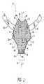
図1〜6は、骨盤底修復に使用するための代表的なインプラントを示す。図1を参照し、前側修復に好適なインプラント10には、下部12及び上部14が含まれる。2つの区別された部分が識別されているが、前側インプラント10は好ましくは、任意の好適な生体適合性メッシュ材料の単一シートで作製されることが理解されよう。したがって、さまざまな部分の仮想的境界線は、前側インプラント10の検討及び議論を容易にするため、図1に点線(仮想線)で示されている。 1-6 show a representative implant for use in pelvic floor repair. Referring to FIG. 1, an
ここで図1に戻り、下部12は全体に漏斗様の形状を有し、長さ範囲約2cm〜約5cmの直線の下縁16と、長さ範囲約8cm〜約14cmの仮想境界線18(図1では点線で示されている)と、女性患者の骨盤の解剖学的形状に似せた複雑な(すなわち複合した)1対の弓形の凹形側縁20、22とによって画定されている。角部24、26はそれぞれ、下縁16が凹形側縁20、22に合流するところで形成される。下縁16は、最長約3cmまで延長することができることに注意されたい(図1に点線で示されている)。 Returning now to FIG. 1, the
下縁16と仮想境界線18との間の距離D1はまた、患者の骨盤の解剖学的形状の関数として選択されるが、典型的には約4cm〜約8cmの範囲に収まる。もちろん、前側インプラント10が作製されるメッシュ布地の性質は、個々の患者のニーズに合わせて外科医が下部12のサイズ及び形状を改変できるようなものである。換言すれば、前側インプラント10の下部12は手術野でカスタムフィットさせることができる。The distance D1 between the
更に図1を参照し、上部14は全体にドーム様の形状を有し、下部12との仮想境界線18と、患者の膀胱頸部に接触しないように選択されたある半径(例えば約2cm〜約4cm)及び弓形長さ(例えば約2cm〜約4cm)を有する曲線上縁28と、骨盤筋膜腱弓(ATFP)に似せた複雑な弓形形状を有する1対の凸形側縁30、32とによって画定されている。上部14の凸形側縁30、32はそれぞれ、下部12の凹形側縁20、22と合流して、それぞれ角34、36を形成し、また上縁28が凸形側縁30、32と合流したところで角38、40が形成される。 Still referring to FIG. 1, the upper portion 14 has an overall dome-like shape and is selected to avoid contact with the virtual boundary 18 with the
仮想境界線18と上縁28との間、前側インプラント10の中央線に沿って測定される距離D2は、患者の骨盤の解剖学的形状の関数として選択される。典型的に、距離D2は約3cm〜約5cmの範囲に収まる。下部12と同様、上部14は、個々の患者のニーズに合わせて手術野でカスタムフィットできるよう適合される。よって、上部14の形状及びサイズは、外科手技の過程で外科医により製造後改変の対象になることが理解されるべきである。The distance D2 measured between the virtual boundary 18 and the upper edge 28 along the center line of the
引き続き図1を参照し、ストラップ様のインプラント延長部42、44は、上部14の両側から外側に延びる。より具体的には、ストラップ様インプラント延長部42は上部14の凸形側縁30から外方向へ横に延び、一方、ストラップ様インプラント延長部44は上部14の凸形側縁32から外方向へ横に延びている。ストラップ様のインプラント延長部42、44の機能については後で詳しく記述されるが、これらは典型的に、幅が約0.5cm〜2cmの範囲、及び長さが約7cm〜約15cmの範囲である。ストラップ様インプラント延長部42、44は、好ましくは図1に示されるようにわずかな湾曲を有しているが、これらは、前側インプラント10の凸形側縁30、32からそれぞれ直線状に延在することもできる。前述のように、外科医は、例えばハサミ又はその他の好適な切断具によって、ストラップ様インプラント延長部42、44の幅及び長さを容易に改変することができる。 With continued reference to FIG. 1, the strap-like implant extensions 42, 44 extend outward from both sides of the upper portion 14. More specifically, the strap-like implant extension 42 extends laterally outward from the
仮想境界線46、48は、全体に中央長手方向軸(L)に平行に延在しており、前側インプラント10の本体を、1つの内側領域A1と、その内側領域A1の両側面に位置する2つの外側領域A2、A3とに分割する。領域A1、A2、及びA3は厳密なものではない。概して、領域A1は、本明細書で詳細が後述されている外科的手技に従って中央又は中間膀胱瘤の修復のために機能する前側インプラント10の部分を指し、一方、領域A2、A3は、同じ手技に従って横方向の膀胱瘤の修復のために機能する前側インプラント10の部分を指す。Imaginary boundary line 46, 48 extends parallel to the central longitudinal axis (L) in the whole, the main body of the
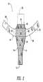
ここで図2を参照し、後側インプラント50には、下部52、上部54、及びテープ部分56が含まれる。前側インプラント10と同様、後側インプラント50は、任意の好適な生体適合性メッシュ材料の単一シートで作製される。後側インプラント50は、前側インプラント10とは別個のものとして区別して図2に示されているが、後側インプラント50は、後で詳しく記述されるように、前側インプラント10と共に一体形成できることが理解されよう。図1の前側インプラント10で記述した場合と同様に、図2の後側インプラント50のさまざまな仮想境界線は、検討及び議論を容易にするため、点線(仮想線)で示されている。 With reference now to FIG. 2, the posterior implant 50 includes a lower portion 52, an upper portion 54, and a tape portion 56. Similar to the
ここで図2に戻り、テープ部分56は下部52と上部54との間に挿入されており、仮想線60、62、64及び66で囲まれてかつ長さ約5cm、幅約0.5〜2cmのほぼ矩形である仮想中央領域58を有している。テープ部分56には、仮想中央領域58の両側から外側に延びる1対のストラップ様インプラント延長部68、70も含まれる。このストラップ様インプラント延長部68、70の機能については後で詳しく記述されるが、ストラップ様インプラント延長部68、70の端が仙棘靱帯に取り付けられる場合は典型的には、幅は約0.5cm〜約2cmの範囲、長さは約4cmであり、又はストラップ様インプラント延長部68、70が仙棘靱帯の通過の有無を問わず臀部から骨盤底を通過する場合には約20cmである。ストラップ様インプラント延長部68、70は、好ましくは図2に示されるようにわずかな湾曲を有しているが、これらは、後側インプラント50の両側から直線状に延在することもできる。後側インプラント50が作製されるメッシュ布地の性質により、外科医は、個々の患者のニーズに合わせてストラップ様インプラント延長部68、70の幅及び長さを容易に改変できる。 Returning now to FIG. 2, the tape portion 56 is inserted between the lower portion 52 and the upper portion 54, surrounded by phantom lines 60, 62, 64 and 66 and having a length of about 5 cm and a width of about 0.5 to It has a virtual central region 58 that is approximately 2 cm rectangular. The tape portion 56 also includes a pair of strap-like implant extensions 68, 70 that extend outward from both sides of the virtual central region 58. The function of this strap-like implant extension 68, 70 will be described in detail later, but typically the width is about .0 when the end of the strap-like implant extension 68, 70 is attached to the sacrospinous ligament. The range is 5 cm to about 2 cm, the length is about 4 cm, or about 20 cm when the strap-like implant extensions 68, 70 pass through the pelvic floor from the buttocks with or without the passage of the sacrospinous ligament. The strap-like implant extensions 68, 70 preferably have a slight curvature as shown in FIG. 2, but they can also extend linearly from both sides of the posterior implant 50. Due to the nature of the mesh fabric from which the posterior implant 50 is made, the surgeon can easily modify the width and length of the strap-like implant extensions 68, 70 to suit individual patient needs.
なおも図2を参照し、全体に三角形をしている下部52は、テープ部分56から下向きに垂れ下がっている。より具体的には、下部52は、長さ約1.5cm〜約3.5cmの範囲を有する直線の下縁72と、直線状又はわずかに凹形の1対の下向きに収束する側縁74、76とによって画定されている。側縁74、76の長さは典型的に、約8cm〜約12cmの範囲であるが、側縁74、76の長さを含む下部52の物理的寸法は、患者の骨盤の解剖学的形状の関数であることが当業者には理解されよう。より具体的には、下部52のサイズ及び形状は、直腸瘤修復の目的に合わせて具体的に選択される。また、下部52の形状及びサイズは、外科医による製造後改変の対象になることも、当業者には理解されよう。直腸瘤修復は必要ないが膣円蓋懸垂が必要な場合は、下部52と上部54との両方を後側インプラント50から除去し、テープ部分56を残して、膣円蓋懸垂を実施する。 Still referring to FIG. 2, the lower portion 52, which is generally triangular, hangs downward from the tape portion 56. More specifically, the lower portion 52 has a straight lower edge 72 having a length in the range of about 1.5 cm to about 3.5 cm, and a pair of downwardly converging side edges 74 that are straight or slightly concave. , 76. The length of the side edges 74, 76 typically ranges from about 8 cm to about 12 cm, but the physical dimensions of the lower portion 52, including the length of the side edges 74, 76, are dependent on the anatomical shape of the patient's pelvis Those skilled in the art will appreciate that More specifically, the size and shape of the lower part 52 are specifically selected in accordance with the purpose of rectal aneurysm repair. Those skilled in the art will also appreciate that the shape and size of the lower portion 52 is subject to post-manufacturing modifications by the surgeon. If rectal aneurysm repair is not required but vaginal cap suspension is required, both lower 52 and upper 54 are removed from posterior implant 50, leaving vaginal cap 56 and performing vaginal cap suspension.
図2を引き続き参照し、上部54は、上縁78の自由端で画定され、あるいはさもなければ長さ約3cm、幅約1cmのほぼ矩形であり、これがテープ部分56から上向きに延びている。上部54の主な目的は、後側インプラント50を前側インプラント10に取り付ける手段を提供することである。よって、前側インプラント10が必要ない患者については、その患者に後側インプラント50を挿入する前に、外科医は後側インプラント50の上部54を取り除くことができることが理解されよう。外科医は、例えば後側インプラント50を前側インプラント10に接合する場合など、患者のニーズに合わせて上部54のサイズ及び形状を違うように改変することもまた、理解されよう。例えば、上縁78は(図2の点線で示すように)約3cmほど延長して、後側インプラント50を前側インプラント10に接合するのを容易にすることができる。あるいは、そのような接合は、前述のように前側インプラント10の下縁16を延長することによっても容易にすることができる。 With continued reference to FIG. 2, the upper portion 54 is defined by the free end of the upper edge 78, or is otherwise generally rectangular with a length of about 3 cm and a width of about 1 cm, which extends upwardly from the tape portion 56. The primary purpose of the upper portion 54 is to provide a means for attaching the posterior implant 50 to the
前側インプラント10と後側インプラント50との両方とも、上述のように大きなメッシュ布地から切断又は型抜きすることができる。必要に応じて、切断したフィラメントの切断端は、当該技術分野において既知の任意の好適な技法によってほつれ防止処理を行うことができる。 Both the
前側インプラント10及び後側インプラント50は、さまざまな標準形状及びサイズ(例えば小、中及び大)で提供され得る。これらの標準インプラントを特定の患者の骨盤の解剖学的形状と比較した後、外科医は、患者のニーズに最もよく適合するものを選択する。選択したインプラントのサイズ及び/又は形状に対する何らかの改変が必要な場合は、外科医が手術野において行うことができる。 The
前側インプラント10は、膀胱瘤の前側修復を行うのに使用され、一方、後側インプラント50は、直腸瘤の後側修復を行うのに使用される。膣円蓋懸垂は、前側インプラント10及び/又は後側インプラント50を使用して実施することができる。これらの治療はすべて、下記に詳しく検討される。 The
下記には、上述の2つの代替実施形態の説明を示し、図10及び11に図示されている。これらの代替の実施形態の記述において、図1及び2の実施形態に関して上述された要素に対応する要素は、対応する番号に100を加えた番号で示される。他に特記のない限り、図10及び11の代替実施形態は、それぞれ図1及び2と同様に構成及び操作される。 The following is a description of the two alternative embodiments described above and is illustrated in FIGS. In the description of these alternative embodiments, elements corresponding to those described above with respect to the embodiment of FIGS. 1 and 2 are indicated by corresponding numbers plus 100. Unless otherwise noted, the alternative embodiments of FIGS. 10 and 11 are configured and operated similarly to FIGS. 1 and 2, respectively.
図3を参照し、前側インプラント110が示されていが、図1の前側インプラント10に比べ、この主な違いには、前側インプラント110の一方の側に2本のストラップ様インプラント延長部142と、前側インプラント110の反対側に2本のストラップ様インプラント延長部144とが提供されていることが含まれる。ストラップ様インプラント延長部142の両方とも、患者の片側の閉鎖孔を通り抜け、一方でストラップ様インプラント延長部144の両方とも、患者のもう一方の側の閉鎖孔を通り抜ける。ストラップ様インプラント延長部142はそれぞれ、身体の一方の側の会陰部(鼠経部)の2つの小さな皮膚切開のうち対応する一方を通って患者の身体から外に出る。同様に、ストラップ様インプラント延長部144はそれぞれ、身体のもう一方の側の会陰部(鼠経部)の2つの小さな皮膚切開のうち対応する一方を通って患者の身体から外に出る。前側インプラント10と比べ、前側インプラント110は、ストラップ様インプラント延長部142、144の余分なセットが提供されている結果、使用中により大きな横方向の支持がもたらされる。この余分のセットの位置により、前側インプラント110を、前側インプラント10に特徴的である角34、36及び38、40なしで製造することが可能になる。 Referring to FIG. 3, an
図4を参照し、後側インプラント150が示されているが、図2の後側インプラント50に比べ、その主な違いには、ストラップ様インプラント延長部168、170が、後側インプラント150の中央長手方向軸(L)に対して鋭角を形成していることが含まれる。この角度は、患者の体内に埋め込まれたときに後側インプラント150が縮んだ場合の、直腸を締め付ける度合を低減するように具体的に選択される。 Referring to FIG. 4, a
図5aは、図1〜3に示されるインプラントに実質的に類似の、前側で又は直腸瘤修復に使用するのに好適なメッシュを示す。インプラント81の中央部分83は、患者の膀胱と膣との間の低張力又は無張力の場所に配置され、これにより間にある筋膜を強化し、膀胱が膣方向に押し付けられるのを防ぐよう設計されている。インプラント81には、インプラントの反対側から外側に延びる、第1セットのストラップ様インプラント延長部85、87と、第2セットのストラップ様インプラント延長部89、91とが含まれる。インプラント延長部85、87、89、91の両セットとも、患者の骨盤筋膜腱弓(ATFP)近くの位置から、閉塞膜を通り、閉鎖孔を通って体外へ出る。上述の経路に沿った組織内のインプラント延長部の経路は、摩擦により、及び最終的にはインプラント内での組織内殖により、インプラントを定位置に固定する。 FIG. 5a shows a mesh that is substantially similar to the implant shown in FIGS. 1-3, suitable for use in the anterior or rectocele repair. The central portion 83 of the implant 81 is placed in a low or no tension location between the patient's bladder and vagina, thereby strengthening the fascia between them and preventing the bladder from being pushed toward the vagina. Designed. The implant 81 includes a first set of strap-like implant extensions 85, 87 and a second set of strap-like implant extensions 89, 91 extending outward from the opposite side of the implant. Both sets of implant extensions 85, 87, 89, 91 pass from the position near the patient's pelvic fascia tendon arch (ATFP) through the obturator and out of the body through the obturator. The path of the implant extension within the tissue along the path described above fixes the implant in place by friction and ultimately by tissue ingrowth within the implant.
図2及び図4に示されるインプラントに実質的に類似の、尖端部、後側/直腸瘤修復のための代表的なインプラントを、図5bに示す。インプラント80には、患者の直腸と膣との間の低張力又は無張力の場所に配置し、これにより直腸と膣との間にある筋膜を強化し、直腸が膣方向に押し付けられるのを防ぐよう設計されている、中央部分82が含まれる。インプラント80には、両側から外側に延びる2本のストラップ様インプラント延長部84、86が含まれる。これらのインプラント延長部は、患者の仙棘靭帯を通って延び、肛門近辺の大臀筋を通って体外に出てるよう設計されている。 A representative implant for apical, posterior / rectal aneurysm repair substantially similar to the implant shown in FIGS. 2 and 4 is shown in FIG. 5b. The
図5cは、前側及び後側の両方の修復に好適なインプラントを示す。組み合わせインプラントのうち、前側部分93及び後側部分95のそれぞれの部分は、上述した個別のインプラントそれぞれに実質的に類似である。 FIG. 5c shows an implant suitable for both anterior and posterior repair. Of the combination implants, the respective portions of the front portion 93 and the back portion 95 are substantially similar to each of the individual implants described above.
ここで図6を参照し、インプラント200は、前側、後側、及び/又は尖端部の膣欠陥を修復するための特定の用途を有して提供される。 Referring now to FIG. 6, an
インプラント200は、前縁210及び後縁211、並びに、図示されるようにわずかに弧状であり得る第1側縁212及び第2側縁213を有する、中央部分201を有する。前縁210は、その内側に向かって延在する陥凹220を有し、後縁は、そこから外側に向かって延びるタブ要素215を有する。図示されるように、この陥凹及びタブ要素は両方ともそれぞれ、前縁及び後縁に沿って実質的に中央にあり、これがインプラントを適切に配置するのに役立つ。加えて、タブ要素215は、必要に応じて子宮に接合するための追加材料を提供する。中央部分は好ましくは、膀胱と、膣の上側2/3との間、あるいは、直腸と、膣の上側2/3との間のいずれかに配置するために、好ましいサイズ及び形状にされる。 The
このインプラントは更に、中央部分から第1及び第2遠位端204、205へと外側に向かって延びる、第1及び第2ストラップ様インプラント延長部202、203を有する。ストラップ様インプラント延長部は、中央本体部分の後縁211の第1端領域221及び第2端領域122から、ある角度で外側に延びており、これにより、中央本体部分201と組み合わせてY字形のインプラントを実質的に形成する。図6に示されるように、好ましい一実施形態において、ストラップ様インプラント延長部の上面223、224を実質的に対称的に縦断する線A及びB、並びに中央本体部分の上面225を実質的に対称的に縦断する線Cは、中央本体部分内で交叉する。 The implant further includes first and second strap-
第1及び第2のストラップ様インプラント延長部202、203はそれぞれ更に、それぞれの遠位端にポケット206、207を含む。各ポケットは、ストラップ様インプラント延長部の遠位端204、205に実質的に隣接した閉じた端230、231と、2つの閉じた側面と、その閉じた端に近位の開放端236、237と、を有し、図示されるように開放端開口部は中央部分201に向いている。好ましくは、この第1及び第2ポケットとその下にあるストラップ様延長部は、図6に示されるように、開放端から閉じた端に向かって内側に先細になっている。 Each of the first and second strap-
好ましい一実施形態において、前縁210は長さaが約30mm、後縁211は長さbが約80mmである。更に、ストラップ様延長部202、203は好ましくは、長さc1、c2が約40mmであり、インプラント200は、全体の幅dが約10.5cm、全体の長さeが約9cmである。 In a preferred embodiment, the
上述のインプラントは、任意の好適な生体適合性材料で構成されてよく、吸収性又は非吸収性、合成又は天然又はこれらの組み合わせであってよい。好ましくはこのインプラントはメッシュタイプの材料であり、一実施形態においては、例えばEthicon,Inc.(Somerville,NJ)からGYNEMESH PSの名で製造及び販売されている押出成形ポリプロピレンフィラメントの編地で構成されている。別の一実施形態において、このメッシュは部分的に吸収性であり、押出成形ポリプロピレンフィラメントと、グリコリド及びイプシロン−カプロラクトンのセグメント化ブロック共重合体フィラメントMONOCRYL(Ethicon,Inc(Somerville,NJ))との編地で構成される。これには例えば、Ethicon,Inc.(Somerville,NJ)からULTRAPROの名で製造及び販売されているものがある。これらの材料は、米国FDAにより、さまざまな用途用で人体内への埋め込みが認可されている。 The implants described above may be composed of any suitable biocompatible material and may be absorbable or non-absorbable, synthetic or natural or a combination thereof. Preferably, the implant is a mesh type material, and in one embodiment, for example, Ethicon, Inc. (Somerville, NJ) and made of extruded polypropylene filaments manufactured and sold under the name GYNEMESH PS. In another embodiment, the mesh is partially absorbent and comprises extruded polypropylene filaments and segmented block copolymer filaments MONOCRYL (Ethicon, Inc (Somerville, NJ)) of glycolide and epsilon-caprolactone. Consists of knitted fabric. This includes, for example, Ethicon, Inc. Some are manufactured and sold under the name ULTRAPRO by (Somerville, NJ). These materials are approved for implantation in the human body by the US FDA for a variety of uses.
インプラントの中央部分は上述のように、少なくとも部分的に、2枚の不織布繊維詰め物の間に挟まれ、これら詰め物を次に一緒にもつれさせる処理をすることにより、インプラントの中央部分を少なくとも部分的に不織布フェルト内に埋め込まれた状態にする。この不織布フェルトは、インプラントの中央部分に配置される。インプラントの中央部分は、修復が必要な組織を支えるインプラント部分となる。図1に示されるインプラント10の中央部分には、上部14及び下部12が含まれ、インプラント110の中央部分には、上部114及び下部112が含まれる。図2に示されるインプラント50の中央部分には、下部52、上部54、及びテープ部分56が含まれ、一方、インプラント150の中央部分には、下部152、上部154、及びテープ部分156が含まれる。図5a〜5c及び図6に示されるインプラントの中央部分は、前述されている。不織布フェルトは、インプラントのストラップ様インプラント延長部には配置されない。不織布フェルト層は、組織内殖を強化するのに必要な構造を提供する。 The central portion of the implant is at least partially sandwiched between two nonwoven fiber paddings, as described above, and then the central portion of the implant is at least partially processed by tangling the padding together. And embedded in a non-woven felt. This nonwoven felt is placed in the central part of the implant. The central portion of the implant becomes the portion of the implant that supports the tissue that needs repair. The central portion of the
不織布繊維詰め物は、繊維業界で既知のさまざまな技法によって形成することができる。不織布繊維詰め物は、紡績、織布又は編布以外のプロセスによって作製される。例えば、不織布繊維詰め物は、紡績、織布又は編布を含むプロセスによって作製された紡績糸、スクリム、網、繊維又はフィラメントから調製することができる。紡績糸、スクリム、網、繊維及び/又はフィラメントは、けん縮されて、互いのもつれを強化されてよい。このようなけん縮された紡績糸、スクリム、網、繊維及び/又はフィラメントは、次いで、もつれるのに十分長い短繊維に切断されてよい。この短繊維を毛羽立てて不織布繊維詰め物を形成してよく、次にこれをもつれさせてもよく、又はカレンダー処理してもよい。更に、短繊維をよじってもよく、又はパイル加工してもよい。不織布繊維詰め物の製造に既知である他の方法を用いてよいが、それらにはエアレイイング、湿式形成及びステッチボンディングのような加工が挙げられる。 Nonwoven fiber fillings can be formed by a variety of techniques known in the textile industry. Nonwoven fiber stuffing is made by processes other than spinning, woven or knitted fabric. For example, non-woven fiber stuffing can be prepared from spun yarns, scrims, nets, fibers or filaments made by processes involving spinning, woven or knitted fabrics. The spun yarns, scrims, nets, fibers and / or filaments may be crimped to strengthen each other's entanglement. Such crimped spun yarns, scrims, nets, fibers and / or filaments may then be cut into short fibers that are long enough to be tangled. The short fibers may be fluffed to form a nonwoven fiber stuffing, which may then be tangled or calendered. Further, the short fibers may be twisted or piled. Other methods known in the manufacture of nonwoven fiber stuffing may be used, including processes such as air laying, wet forming and stitch bonding.
不織布繊維詰め物は繊維で構成される。不織布繊維詰め物の作製に使用される繊維は、単繊維、紡績糸、糸、編組、又は繊維の束であり得る。上述の任意の構造において、材料の機械的特性は、繊維製品の密度若しくは質感を変えることによって、又は不織布を作製するのに使用する繊維中に粒子を埋め込むことによって、変えることができる。本発明に使用される不織布繊維詰め物の密度は、1〜10mg/cm2、好ましくは2〜6mg/cm2である。Nonwoven fiber stuffing is composed of fibers. The fibers used to make the nonwoven fiber stuffing can be single fibers, spun yarns, yarns, braids, or bundles of fibers. In any of the structures described above, the mechanical properties of the material can be altered by changing the density or texture of the textile product or by embedding particles in the fibers used to make the nonwoven. The density of the nonwoven fiber wadding to be used in the present invention, 1~10mg / cm2, preferably 2-6 mg / cm2.
不織布繊維詰め物を作製するのに使用される繊維は、生体適合性、生体吸収性のポリマーから作製される。好適な生体適合性、生体吸収性のポリマーの例としては、脂肪族ポリエステル、ポリ(アミノ酸)、コポリ(エーテル−エステル)、ポリアルキレンオキサレート、ポリアミド、チロシン誘導ポリカーボネート、ポリ(ポリイミノカーボネート)、ポリオルトエステル、ポリオキサエステル、ポリアミドエステル、アミン基含有ポリオキサエステル、ポリ(無水物)、ポリホスファゼン、生体分子(すなわち、例えばコラーゲン、エラスチン、生体吸収性澱粉などのバイオポリマー)及びこれらのブレンドからなる群から選択されるポリマーが挙げられる。 The fibers used to make the nonwoven fiber stuffing are made from a biocompatible, bioabsorbable polymer. Examples of suitable biocompatible, bioabsorbable polymers include aliphatic polyesters, poly (amino acids), copoly (ether-esters), polyalkylene oxalates, polyamides, tyrosine-derived polycarbonates, poly (polyiminocarbonates), Polyorthoesters, polyoxaesters, polyamide esters, amine group-containing polyoxaesters, poly (anhydrides), polyphosphazenes, biomolecules (ie biopolymers such as collagen, elastin, bioabsorbable starches) and blends thereof And a polymer selected from the group consisting of:
本発明の目的のため、脂肪族ポリエステルには、ラクチド(乳酸、D−、L−、及び/又はmeso−ラクチドを含む)、グリコリド(グリコール酸を含む)、イプシロン−カプロラクトン、p−ジオキサノン(1,4−ジオキサン−2−オン)、トリメチレンカーボネート(1,3−ジオキサン−2−オン)、トリメチレンカーボネートのアルキル誘導体、及びこれらの混合物からなる群から選択されるモノマーの、ホモポリマー及びコポリマーが挙げられるが、これらに限定されない。一実施形態において、この繊維は、ラクチド、グリコリド、及びp−ジオキサン、及びこれらのブレンドからなる群から選択されるモノマーの、ホモポリマー及びコポリマーから構成される。更に別の一実施形態において、この繊維は90/10ポリ(グリコリド−co−ラクチド)(90/10 PGA/PLA)で構成される。更に別の一実施形態において、この繊維は、(90/10 PGA/PLA)繊維対ポリ(p−ジオキサン)(PDO)繊維の比が50:50の繊維で構成される。 For the purposes of the present invention, aliphatic polyesters include lactide (including lactic acid, D-, L-, and / or meso-lactide), glycolide (including glycolic acid), epsilon-caprolactone, p-dioxanone (1 , 4-dioxan-2-one), trimethylene carbonate (1,3-dioxan-2-one), alkyl derivatives of trimethylene carbonate, and homopolymers and copolymers of monomers selected from the group consisting of mixtures thereof However, it is not limited to these. In one embodiment, the fiber is composed of homopolymers and copolymers of monomers selected from the group consisting of lactide, glycolide, and p-dioxane, and blends thereof. In yet another embodiment, the fiber is composed of 90/10 poly (glycolide-co-lactide) (90/10 PGA / PLA). In yet another embodiment, the fibers are comprised of fibers having a ratio of (90/10 PGA / PLA) fibers to poly (p-dioxane) (PDO) fibers of 50:50.
不織布繊維詰め物は、メッシュインプラントの中央部分を2枚の不織布詰め物の2層の間に少なくとも部分的に挟み込むことによって、インプラントと組み合わせられる。不織布繊維詰め物は、空気絡合、ニードルパンチング、水力絡合、及び同様の方法などのプロセスを介してインプラントに接合することができ、これによりインプラントの中央部分の少なくとも一部分が不織布フェルトに埋め込まれる。これらのプロセスではそれぞれ、エアジェット、ニードル又は鉤付きニードル、及びウォータージェットを使用して、不織布フェルトの繊維と骨盤底デバイスとの間の連結を提供する。ジェット作用及びニードルパンチングにより、組織内殖のためのチャンネルが更に提供される。 The nonwoven fiber stuffing is combined with the implant by sandwiching the central portion of the mesh implant at least partially between two layers of two nonwoven stuffings. The nonwoven fiber stuffing can be joined to the implant via processes such as air entanglement, needle punching, hydraulic entanglement, and the like, whereby at least a portion of the central portion of the implant is embedded in the nonwoven felt. Each of these processes uses air jets, needles or barbed needles, and water jets to provide a connection between the fibers of the nonwoven felt and the pelvic floor device. Jet action and needle punching further provide a channel for tissue ingrowth.
一実施形態において、不織布繊維詰め物はニードルパンチングを介してインプラントに接合される。この方法は、不織布繊維詰め物をインプラントの中央部分の各面に配置することによって、2枚の不織布繊維詰め物の間にインプラントの中央部分を少なくとも部分的に挟み込むことを必要とする。この作成物を次にニードルパンチ機に通すことによって、一連の鉤付きニードルが作成物を貫通し、繊維を引っ張ることによって、この2枚の不織布繊維詰め物層を絡み合わせ、インプラントの中央部分を少なくとも部分的に、不織布フェルト内に埋め込む。ニードルパンチ通過の回数は、作成物の最終的な厚さ、密度、及び層間剥離耐性に依存する。例えば、ニードルパンチ通過の回数は、約1回〜約10回の範囲であり得る。一実施形態において、好ましい通過回数は約2回である。 In one embodiment, the nonwoven fiber filling is joined to the implant via needle punching. This method entails at least partially sandwiching the central portion of the implant between two nonwoven fiber stuffings by placing the nonwoven fiber stuffing on each side of the central portion of the implant. By passing the product through a needle punch machine, a series of barbed needles penetrates the product and pulls the fibers so that the two nonwoven fiber stuffing layers are intertwined and at least the central portion of the implant is Partially embedded in non-woven felt. The number of needle punch passes depends on the final thickness, density, and delamination resistance of the product. For example, the number of needle punch passes can range from about 1 to about 10 times. In one embodiment, the preferred number of passes is about two.
別の一実施形態において、不織布繊維詰め物は、水力絡合を介してメッシュインプラントの中央部分に接合される。この方法は、インプラントの中央部分の各面に配置された2枚の不織布繊維詰め物の間にインプラントの中央部分を少なくとも部分的に挟み込むことを必要とする。この作成物は、裏材メッシュ上に配置され、次にコンベアベルト又は開放表面ドラムの上に置かれる。ベルト/ドラムによって、一連のウォータージェットの中を作成物が通過する。高圧のウォータージェットを使用することにより、不織布フェルトの繊維がメッシュを通って押し込まれて絡まり、水はすぐに消散する。ベルト/ドラムの下を真空にすることにより、過剰な水が除去される。ウォータージェットを通過したら、作成物を裏返して、もう1回ウォータージェットを通過させる。絡合後、この作成物を乾燥させ、残った水を除去する。 In another embodiment, the nonwoven fiber filling is joined to the central portion of the mesh implant via hydraulic entanglement. This method entails at least partially sandwiching the central portion of the implant between two nonwoven fibrous fillings disposed on each side of the central portion of the implant. This product is placed on a backing mesh and then placed on a conveyor belt or open surface drum. The belt / drum passes the product through a series of water jets. By using a high pressure water jet, the fibers of the nonwoven felt are pushed through the mesh and become entangled, and the water is immediately dissipated. Excess water is removed by applying a vacuum under the belt / drum. After passing the water jet, turn the product upside down and let it pass once more. After entanglement, the product is dried and the remaining water is removed.
全体のデバイスの厚さ、密度及び層間剥離耐性に影響するプロセス変数はたくさんあるが、これには、水圧、ウォータージェット通過の回数、裏材メッシュの孔径、及びベルト/ドラム速度が挙げられる。水圧は、約3447kPa(500psi)〜約3000psiの範囲であり得る。一実施形態において、水圧は約10342kPa(1500psi)〜13790kPa(2000psi)の範囲である。ウォータージェット通過の回数は、シート各面について約1回〜約10回の範囲であり得る。一実施形態において、ウォータージェット通過は各面について約3回〜約6回の範囲である。裏材メッシュ孔径は、約200×200マイクロメートル〜2000×2000マイクロメートルの範囲であり得る。一実施形態において、メッシュ孔径は、約400×400マイクロメートル(ASTM #40メッシュ)の範囲である。ベルト/ドラム速度は、3.0メートル/分(10ft/分)〜18.3メートル/分(60ft/分)の範囲であり得る。一実施形態において、ベルト/ドラム速度は、約10.7メートル/分(35ft/分)〜約13.7メートル/分(45ft/分)の範囲である。 There are many process variables that affect overall device thickness, density, and delamination resistance, including water pressure, number of water jet passes, backing mesh pore size, and belt / drum speed. The water pressure may range from about 3447 kPa (500 psi) to about 3000 psi. In one embodiment, the water pressure ranges from about 10342 kPa (1500 psi) to 13790 kPa (2000 psi). The number of water jet passes can range from about 1 to about 10 times for each side of the sheet. In one embodiment, the water jet passage ranges from about 3 to about 6 times for each side. The backing mesh pore size can range from about 200 x 200 micrometers to 2000 x 2000 micrometers. In one embodiment, the mesh pore size is in the range of about 400 x 400 micrometers (ASTM # 40 mesh). The belt / drum speed can range from 3.0 meters / minute (10 ft / minute) to 18.3 meters / minute (60 ft / minute). In one embodiment, the belt / drum speed ranges from about 10.7 meters / minute (35 ft / minute) to about 13.7 meters / minute (45 ft / minute).
インプラントの中央部分は、少なくとも部分的に、不織布繊維詰め物の間に挟まれている。不織布繊維詰め物の間にインプラントの中央部分を部分的に挟み込むには、接合の前に、覆われるインプラント領域に合うように不織布繊維詰め物をあらかじめ切断すること;不織布繊維詰め物でデバイス全体を覆い、望ましい領域にその不織布繊維詰め物を接合してから、余分の不織布繊維詰め物をトリミングすること;又は、メッシュシートに不織布繊維詰め物を接合してから、インプラントの形状に切り抜くこと、によって達成することができる。不織布フェルト又はメッシュインプラントの切断は、レーザー若しくはダイカットによって、又はハサミなどの機械的手段を使用することによって、達成可能である。 The central portion of the implant is at least partially sandwiched between the nonwoven fiber fillings. To partially sandwich the central portion of the implant between the nonwoven fiber fillings, pre-cutting the nonwoven fiber fillings to fit the covered implant area prior to joining; This can be achieved by joining the nonwoven fiber filling to the area and then trimming the excess nonwoven fiber filling; or joining the nonwoven fiber filling to the mesh sheet and then cutting into the shape of the implant. Cutting the nonwoven felt or mesh implant can be accomplished by laser or die cutting or by using mechanical means such as scissors.
組織エンジニアリングデバイスの合計厚さは、0.5〜3ミリメートルであり得、好ましくは0.6〜1.2ミリメートルであり得る。本発明の不織布の合計密度は、50mg/mL〜3000mg/mL、好ましくは50mg/mL〜300mg/mL、より好ましくは60mg/mL〜90mg/mLであり得る。 The total thickness of the tissue engineering device can be from 0.5 to 3 millimeters, preferably from 0.6 to 1.2 millimeters. The total density of the nonwoven fabric of the present invention can be 50 mg / mL to 3000 mg / mL, preferably 50 mg / mL to 300 mg / mL, more preferably 60 mg / mL to 90 mg / mL.
本明細書に記述されている骨盤底修復治療のための組織エンジニアリングデバイスは、抗癒着性バリア、生物活性剤、細胞、刻んだ組織及び細胞可溶化物を組み込むことによって、更に強化することができる。 The tissue engineering device for pelvic floor repair treatment described herein can be further enhanced by incorporating anti-adhesion barriers, bioactive agents, cells, minced tissue and cell lysates. .
一実施形態において、本発明のデバイスには、手術後の組織癒着を防ぐための抗癒着性バリアを組み込むことができる。好適な抗癒着性バリアには、ヒアルロン酸及びその誘導体;ポリ(エチレングリコール);酸化された再生セルロース(膜又はゲルの形態で);及び同様物が挙げられるが、これらに限定されない。 In one embodiment, the devices of the present invention can incorporate an anti-adhesion barrier to prevent post-surgical tissue adhesion. Suitable anti-adhesion barriers include, but are not limited to, hyaluronic acid and its derivatives; poly (ethylene glycol); oxidized regenerated cellulose (in the form of a membrane or gel); and the like.
一実施形態において、1つ以上の生物活性剤を、本明細書に記述されている組織エンジニアリングデバイス内に組み込むか、及び/又はこれに適用することができる。一実施形態において、生物活性剤はインプラントに組み込まれるか、又はコーティングされる。別の実施形態では、生物活性剤は不織布フェルト層に組み込まれる。 In one embodiment, one or more bioactive agents can be incorporated into and / or applied to the tissue engineering devices described herein. In one embodiment, the bioactive agent is incorporated into the implant or coated. In another embodiment, the bioactive agent is incorporated into the nonwoven felt layer.
好適な生物活性剤としては、感染予防剤(例えば、抗菌剤及び抗生物質)、炎症を緩和する製剤(例えば、抗炎症薬)、酸化再生セルロースのような、接着形成を防ぐ又は最低限にする製剤(例えば、Ethicon,Inc.から入手可能なINTERCEED及びSURGICEL)及びヒアルロン酸、免疫系を抑制する製剤(例えば、免疫抑制剤)、異種又は同種異系の増殖因子、タンパク質(マトリックスタンパク質を含む)、ペプチド、抗体、酵素、血小板、血小板の豊富な血漿、糖タンパク質、ホルモン(例えばエストロゲンクリーム)、サイトカイン、グリコサミノグリカン、核酸、鎮痛剤、ウイルス、ウイルス粒子、及び細胞型、走化性物質、抗生物質、及びステロイド及び非ステロイド鎮痛剤が挙げられるが、これらに限定されない。 Suitable bioactive agents include preventive agents (eg, antibacterials and antibiotics), formulations that relieve inflammation (eg, anti-inflammatory agents), oxidized regenerated cellulose, or prevent or minimize adhesion formation. Formulations (eg, INTEREDED and SURGICEL available from Ethicon, Inc.) and hyaluronic acid, formulations that suppress the immune system (eg, immunosuppressants), xenogeneic or allogeneic growth factors, proteins (including matrix proteins) , Peptides, antibodies, enzymes, platelets, platelet-rich plasma, glycoproteins, hormones (eg estrogen cream), cytokines, glycosaminoglycans, nucleic acids, analgesics, viruses, virus particles, and cell types, chemotactic substances , Antibiotics, and steroids and nonsteroidal analgesics. Not.
本発明の組織エンジニアリングデバイスに、生存組織を含めることもできる。供給源は様々であってよく、組織は様々な形状を有することができるが、一実施形態では、組織は、組織再生の有効性を高め、かつ治癒反応を促進する微細分化された組織断片の形態である。別の実施形態では、生活組織は、組織再生及び/又は再形成の能力がある生存細胞を含有する健常組織から採取可能な、組織切片又はストリップの形態であってよい。 Living tissue can also be included in the tissue engineering device of the present invention. While the source can vary and the tissue can have a variety of shapes, in one embodiment, the tissue increases the effectiveness of tissue regeneration and promotes a finely differentiated tissue fragment that promotes a healing response. It is a form. In another embodiment, living tissue may be in the form of tissue sections or strips that can be harvested from healthy tissue containing viable cells capable of tissue regeneration and / or remodeling.
組織エンジニアリングデバイスには、その中に細胞を組み込むこともできる。好適な細胞型としては、骨細胞、骨芽細胞、破骨細胞、線維芽細胞、幹細胞、多能性細胞、軟骨細胞前駆体、軟骨細胞、内皮細胞、マクロファージ、白血球、含脂肪細胞、単球、形質細胞、マスト細胞、臍帯細胞、間質細胞、間葉幹細胞、上皮細胞、筋芽細胞、腱細胞、靭帯線維芽細胞、神経細胞、骨髄細胞、滑膜細胞、胚幹細胞、脂肪組織由来前駆細胞、末梢血前駆細胞、成体組織から単離される幹細胞、遺伝子組換え細胞、軟骨細胞とその他の細胞の組み合わせ、骨細胞とその他の細胞の組み合わせ、滑膜細胞とその他の細胞の組み合わせ、骨髄細胞とその他の細胞の組み合わせ、間葉細胞とその他の細胞の組み合わせ、間質細胞とその他の細胞の組み合わせ、幹細胞とその他の細胞の組み合わせ、胚幹細胞とその他の細胞の組み合わせ、成体組織から単離される前駆細胞とその他の細胞の組み合わせ、末梢血前駆細胞とその他の細胞の組み合わせ、成体組織から単離される幹細胞とその他の細胞の組み合わせ、遺伝子組換え細胞とその他の細胞の組み合わせが挙げられるが、これらに限定されない。 A tissue engineering device can also incorporate cells therein. Suitable cell types include bone cells, osteoblasts, osteoclasts, fibroblasts, stem cells, pluripotent cells, chondrocyte precursors, chondrocytes, endothelial cells, macrophages, leukocytes, adipocytes, monocytes , Plasma cells, mast cells, umbilical cells, stromal cells, mesenchymal stem cells, epithelial cells, myoblasts, tendon cells, ligament fibroblasts, neurons, bone marrow cells, synovial cells, embryonic stem cells, adipose tissue-derived precursors Cells, peripheral blood progenitor cells, stem cells isolated from adult tissues, genetically modified cells, combinations of chondrocytes and other cells, combinations of bone cells and other cells, combinations of synovial cells and other cells, bone marrow cells And other cell combinations, mesenchymal cell and other cell combinations, stromal cell and other cell combinations, stem cell and other cell combinations, embryonic stem cell and other cell combinations A combination of progenitor cells and other cells isolated from adult tissue, a combination of peripheral blood progenitor cells and other cells, a combination of stem cells and other cells isolated from adult tissue, a combination of genetically modified cells and other cells However, it is not limited to these.
組織エンジニアリングデバイスはまた、核酸、ウイルス、又はウイルス粒子が関心対象の遺伝子を送達する遺伝子療法でも使用することができるが、これは、少なくとも1つの関心対象の遺伝子産物を特定の細胞又は細胞型にエンコードする。したがって、生物活性剤は、核酸(例えば、DNA、RNA、又はオリゴヌクレオチド)、ウイルス、ウイルス粒子、又は非ウイルスベクターであってよい。ウイルス及びウイルス粒子は、DNA又はRNAウイルスであってもよく、DNA又はRNAウイルス由来であってもよい。関心対象の遺伝子産物は、好ましくは、タンパク質、ポリペプチド、干渉リボ核酸(iRNA)、及びこれらの組み合わせからなる群から選択される。 Tissue engineering devices can also be used in gene therapy where a nucleic acid, virus, or viral particle delivers a gene of interest, which involves at least one gene product of interest in a particular cell or cell type. Encode. Thus, the bioactive agent can be a nucleic acid (eg, DNA, RNA, or oligonucleotide), a virus, a viral particle, or a non-viral vector. The virus and virus particle may be a DNA or RNA virus, or may be derived from a DNA or RNA virus. The gene product of interest is preferably selected from the group consisting of proteins, polypeptides, interfering ribonucleic acids (iRNA), and combinations thereof.
適用可能な核酸及び/又はウイルス性因子(すなわち、ウイルス又はウイルス粒子)が強化された細胞マトリックスに組み込まれたら、デバイスを特定の部位に移植して、望ましいタイプの生物学的反応を引き出すことができる。次に、核酸又はウイルス性因子は細胞に取り込まれることでき、この核酸又はウイルス性因子がコード化する任意のタンパク質が、この細胞によって局所的に生成され得る。一実施形態では、核酸又はウイルス性因子は、細分化組織懸濁液の組織片内の細胞に取り込まれることでき、又は代替実施形態では、核酸又はウイルス性因子は、傷害組織部位を取り囲む組織の中の細胞に取り込まれることできる。生成されるタンパク質は、上記の種類のタンパク質であることができ、又は損傷若しくは疾患を治癒する、感染と闘う、若しくは炎症反応を軽減する組織の能力を向上させるのを容易にする同様のタンパク質であってよいことがを、当業者は認識されよう。組織修復過程又はその他の通常の生物学的過程に悪影響を与える可能性がある不必要な遺伝子産物の発現を阻止するために、核酸を使用することも可能である。DNA、RNA、及びウイルス剤は、多くの場合、遺伝子発現ノックアウトとしても知られるこのような発現阻止機能を達成するために使用される。 Once applicable nucleic acids and / or viral factors (ie, viruses or viral particles) have been incorporated into the enhanced cell matrix, the device can be implanted at a specific site to elicit the desired type of biological response. it can. The nucleic acid or viral factor can then be taken up by the cell and any protein encoded by the nucleic acid or viral factor can be locally produced by the cell. In one embodiment, the nucleic acid or viral factor can be taken up by cells within the tissue piece of the subdivision tissue suspension, or in an alternative embodiment, the nucleic acid or viral factor is of tissue surrounding the damaged tissue site. Can be taken up by cells inside. The protein produced can be a protein of the type described above, or a similar protein that facilitates improving the ability of the tissue to heal an injury or disease, fight infection or reduce the inflammatory response. Those skilled in the art will recognize that this may be the case. Nucleic acids can also be used to block the expression of unwanted gene products that can adversely affect tissue repair processes or other normal biological processes. DNA, RNA, and viral agents are often used to achieve such an expression blocking function, also known as gene expression knockout.
下記の実施例は本発明の原理及び実践の説明のためであり、これらに限定されるものではない。本発明の範囲及び趣旨内の多くの追加の実施形態は、ひとたびこの開示の利益を得ると、当業者に明らかになるであろう。 The following examples are illustrative of the principles and practices of the present invention, but are not limited thereto. Many additional embodiments within the scope and spirit of the present invention will become apparent to those skilled in the art once they benefit from this disclosure.
実施例1:ニードルパンチングによる骨盤底修復用組織エンジニアリングデバイスの製造(GYNEMESH PSメッシュ+90/10 PGA/PLA不織布)
90/10(mol %)ポリ(グリコリド−co−ラクチド)(90/10 PGA/PLA)繊維の不織布繊維詰め物(密度2mg/cm2)が、Concordia Manufacturing,LLC(Coventry,RI)で調製された。GYNEMESH PSメッシュ(Ethicon Inc(Somerville,NJ))の15cm×15cm片を、そのメッシュの各面に不織布詰め物を配置することによって、不織布繊維詰め物の間に挟んだ。この作成物を次に、ニードルパンチ機に通して繊維詰め物を連結させ、これによりメッシュを不織布フェルト内に埋め込んだ。ニードルパンチに2回通して、デバイスを作製した。GYNEMESH PSメッシュ+90/10 PGA/PLA不織布スカフォールドは、厚さ1.17mm、密度75mg/ccであった。Example 1: Manufacture of tissue engineering device for pelvic floor repair by needle punching (GYNEMESH PS mesh + 90/10 PGA / PLA nonwoven fabric)
Nonwoven fiber stuffing (
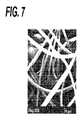
試料を走査電子顕微鏡(SEM)で分析した。試料を顕微鏡のスタッドに装着し、EMS 550スパッタコーター(Electron Microscopy Sciences(Hatfield,PA))を用いて金の薄層をコーティングした。SEM解析は、JEOL JSM−5900LV SEM(JEOL(Peabody,MA))を用いて行った。各試料について表面を検査した。代表的なSEM顕微鏡写真を図7に示す。このSEMは、メッシュの太いポリプロピレン繊維が、不織布フェルトの90/10 PGA/PLA繊維内に連結されているのを示している。 Samples were analyzed with a scanning electron microscope (SEM). The sample was mounted on a microscope stud and coated with a thin layer of gold using an EMS 550 sputter coater (Electron Microscience Sciences (Hatfield, PA)). SEM analysis was performed using JEOL JSM-5900LV SEM (JEOL (Peabody, MA)). The surface was inspected for each sample. A representative SEM micrograph is shown in FIG. This SEM shows that the thick polypropylene fibers are connected within the 90/10 PGA / PLA fibers of the nonwoven felt.
実施例2:ニードルパンチングによる骨盤底修復用組織エンジニアリングデバイスの製造(ULTRAPROメッシュ+90/10 PGA/PLA不織布)
90/10 PGA/PLA繊維の不織布繊維詰め物(密度2mg/cm2)が、Concordia Manufacturing,LLC(Coventry,RI)で調製された。ULTRAPROメッシュ(Ethicon Inc(Somerville,NJ))の15cm×15cm片を、そのメッシュの各面に不織布詰め物を配置することによって、不織布繊維詰め物の間に挟んだ。この作成物を次に、ニードルパンチ機に通して繊維詰め物を連結させ、これによりメッシュを不織布フェルト内に埋め込んだ。ニードルパンチに2回通して、デバイスを作製した。ULTRAPROメッシュ+90/10 PGA/PLA不織布スカフォールドは、厚さ1.03mm、密度71mg/ccであった。Example 2: Production of tissue engineering device for pelvic floor repair by needle punching (ULTRAPRO mesh + 90/10 PGA / PLA nonwoven fabric)
A 90/10 PGA / PLA fiber nonwoven fiber stuffing (
上述のように調製された組織エンジニアリングデバイスを、破裂試験用に4cm×4cmに切断した。デバイスの破裂試験は、ミューレン破裂試験装置を使用して評価された。試料を試験装置のクランプ領域に置いた。このクランプを作動させて、試料をゴム製試験隔膜上の位置に保持した。ゴム製隔膜に水圧液で圧力をかけ、一定の速度で圧力を増大させて、クランプ固定されたメッシュに対して隔膜を膨張させた。試料が破裂するまで隔膜の加圧を続けた。破裂点での圧力(kPa(平方インチ当たりポンド))を、破裂強度として記録した。データは、n=5での平均±標準偏差を示す。
実施例3:ニードルパンチングによる骨盤底修復用組織エンジニアリングデバイスの製造(GYNEMESH PSメッシュ+不織布詰め物は(90/10 PGA/PLA)繊維:PDO繊維を50:50の比で有する)
90/10 PGA/PLA繊維とポリジオキサノン(PDO)繊維を50:50の比で有する不織布繊維詰め物(密度1mg/cm2)が、Concordia Manufacturing,LLC(Coventry,RI)で調製された。GYNEMESH PSメッシュ(Ethicon Inc(Somerville,NJ))の15cm×15cm片を、そのメッシュの各面に不織布詰め物を配置することによって、不織布繊維詰め物の間に挟んだ。この作成物を次に、ニードルパンチ機に通して繊維詰め物を連結させ、これによりメッシュを不織布フェルト内に埋め込んだ。ニードルパンチに2回通して、デバイスを作製した。GYNEMESH PSメッシュ+(50:50)(90/10 PGA/PLA):PDO不織布スカフォールドは、厚さ0.97mm、密度60mg/ccであった。Example 3: Manufacture of tissue engineering device for pelvic floor repair by needle punching (GYNEMESH PS mesh + nonwoven stuffing has (90/10 PGA / PLA) fibers: PDO fibers in a ratio of 50:50)
Nonwoven fiber stuffing (density 1 mg / cm2 ) having 90/10 PGA / PLA fibers and polydioxanone (PDO) fibers in a ratio of 50:50 was prepared at Concordia Manufacturing, LLC (Coventry, RI). A 15 cm x 15 cm piece of GYNEMESH PS mesh (Ethicon Inc (Somerville, NJ)) was sandwiched between the nonwoven fiber stuffing by placing the nonwoven stuffing on each side of the mesh. This preparation was then passed through a needle punch machine to connect the fiber filling, thereby embedding the mesh in the nonwoven felt. The device was fabricated by passing twice through the needle punch. GYNEMESH PS mesh + (50:50) (90/10 PGA / PLA): The PDO nonwoven fabric had a thickness of 0.97 mm and a density of 60 mg / cc.
実施例4:コラーゲンフィブリル付着
実施例1に記述したスカフォールドに、下記の手順に従ってヒト線維芽細胞を播種した:スカフォールドのダイ打ち抜きディスク(6mm)をエチレンオキシドで滅菌し、24ウェル低結合プレートのウェルに入れた。スカフォールドディスクをDMEM培地で洗い、ヒト線維芽細胞を播種し、次に21日間37℃の加湿インキュベーター中(95%空気:5% CO2)でインキュベートした。細胞を播種したディスクをホルマリンで固定した後、パラフィンに埋め込んだ。Example 4: Collagen fibril attachment The scaffold described in Example 1 was seeded with human fibroblasts according to the following procedure: Scaffold die punched discs (6 mm) were sterilized with ethylene oxide and placed in wells of a 24-well low binding plate. I put it in. Scaffold disks were washed with DMEM medium, seeded with human fibroblasts, and then incubated for 21 days in a 37 ° C. humidified incubator (95% air: 5% CO2 ). The cells seeded discs were fixed with formalin and then embedded in paraffin.
断面をシリウスレッドで染色し、付着したコラーゲンの複屈折パターンを見るため、偏光顕微鏡で観察した。不織布スカフォールドの繊維内に十分に一体化した、新たに合成されたコラーゲンフィブリルがしっかりと付着していたことが見出された。 The cross section was stained with sirius red and observed with a polarizing microscope to see the birefringence pattern of the attached collagen. It was found that newly synthesized collagen fibrils, well integrated into the fibers of the nonwoven scaffold, were firmly attached.
実施例5:ウサギ筋膜修復研究
実施例1及び3で調製された組織エンジニアリングデバイスを、骨盤底修復に関して、ニュージーランドホワイト(NZW)ウサギの筋膜内モデルにおいて評価した。Example 5 Rabbit Fascial Repair Study The tissue engineering devices prepared in Examples 1 and 3 were evaluated in a New Zealand White (NZW) rabbit intrafascial model for pelvic floor repair.
動物管理
本研究に使用された動物は、動物福祉法最終規定(Final Rules of the Animal Welfare Act regulations)(9 CFR)、実験動物の人道的管理と使用に関する公衆衛生局規範(Public Health Service Policy on Humane Care and Use of Laboratory Animals)、及び実験動物の管理と使用のガイド(Guide for the Care and Use of Laboratory Animals)の該当するすべての条項に準拠して取扱いと管理が行われた。この研究における動物の管理又は使用を含むプロトコル、及び任意の改正又は手順は、このような手順の開始前に、試験機関の動物の管理及び使用委員会(Institutional Animal Care and Use Committee)により査察及び承認された。Animal Management The animals used in this study are the Final Rules of the Animal Welfare Act regulations (9 CFR), the Public Health Service Policy on the Humanitarian Management and Use of Laboratory Animals. The handling and management was done in accordance with all applicable provisions of the Humane Care and Use of Laboratory Animals) and Guide for the Care and Use of Laboratory Animals. Protocols, including any animal management or use in this study, and any amendments or procedures should be reviewed and reviewed by the Institutional Animal Care and Use Committee before the start of such procedures. approved.
動物は、USDA規制に適合するステンレススチール製のケージに個別に収容された。12時間明/12時間暗の光周期が維持された。室温は標的範囲(16〜22℃(61〜72°F))以内、標的湿度30〜70% RHに維持された。動物には標準のウサギ用固形飼料を1日に少なくとも2回与え、十分な水を制約なしに与えた。 Animals were individually housed in stainless steel cages that meet USDA regulations. A 12 hour light / 12 hour dark photoperiod was maintained. Room temperature was maintained within the target range (16-22 ° C (61-72 ° F)) and target humidity 30-70% RH. Animals were fed standard rabbit chow at least twice a day and given enough water without restriction.
材料及び方法
動物
手順はすべて、無菌条件下で実施された。手術の前に、適切な薬剤を投与し、ケタミンを使用して全身麻酔が導入された。全身麻酔は酸素中に供給されたイソフルランで維持された。少なくとも長さ3cmの1本の中線切開を、動物の背面上、尾部から最終肋骨まで行った。別に、背の右側面と左側面の両方の表面の浅筋膜において、中線から約1cm外れた位置に、2本の切開を行った。この中央から外れた切開の長さは少なくとも3cmであった。中線から約2〜3cm離れ、尾部から最終肋骨まで、深筋膜に約1cm×2cmの欠損を形成した。試験物品(1cm×2cm)をこの欠損内に配置し、寸法に合わせてトリミングした。材料は、連続パターンで5−0 PDSで定位置に縫合した。Materials and Methods Animal procedures All procedures were performed under aseptic conditions. Prior to surgery, appropriate drugs were administered and general anesthesia was introduced using ketamine. General anesthesia was maintained with isoflurane supplied in oxygen. A midline incision at least 3 cm in length was made on the back of the animal from the tail to the final rib. Separately, two incisions were made in the superficial fascia on both the right and left dorsal surfaces at a position approximately 1 cm away from the midline. The length of the off-center incision was at least 3 cm. A defect of about 1 cm × 2 cm was formed in the deep fascia from about 2 to 3 cm away from the midline and from the tail to the final rib. A test article (1 cm × 2 cm) was placed in the defect and trimmed to size. The material was sewn in place with 5-0 PDS in a continuous pattern.
試験材料
組織エンジニアリングデバイスは、実施例1及び3に記述されているようにニードルパンチングで調製された。試験材料を2×3cmの切片に切り、エチレンオキシドで滅菌した。メッシュのみの対照として用いたGYNEMESH PSは、2×3cmの切片にトリミングされ、滅菌された。Test Materials Tissue engineering devices were prepared by needle punching as described in Examples 1 and 3. The test material was cut into 2 × 3 cm sections and sterilized with ethylene oxide. GYNEMESH PS used as a mesh only control was trimmed into 2 × 3 cm sections and sterilized.
組織内殖の評価
埋め込みから60(±2)日後及び120(±2)日後、動物をペントバルビタールナトリウム溶液の静脈内過用量注入によって安楽死させた後、大腿部血管を切ることによって放血させた。次に、動物本来の組織を境界線として、インプラント部位を摘出した。各インプラントを横断方向に二分し、頭部端をプラスチック材料に接合し、10%の中性緩衝ホルマリン内で固定した。各インプラントの頭端のホルマリン固定後、この部位をトリミングして、インプラント材料が最大量になるような面で、1つの断面を得た。トリミングされた標本はパラフィン埋め込みの処理を行い、ヘマトキシリン及びエオシン染色されたスライド/ブロックを得た。Evaluation of tissue ingrowth 60 (± 2) and 120 (± 2) days after implantation, the animals were euthanized by intravenous overdose injection of pentobarbital sodium solution and then exsanguinated by cutting the femoral blood vessels. It was. Next, the implant site was extracted using the original tissue of the animal as the boundary line. Each implant was bisected in the transverse direction and the head end was joined to a plastic material and fixed in 10% neutral buffered formalin. After formalin fixation of the head end of each implant, this site was trimmed to obtain one cross section in a plane that would maximize the amount of implant material. Trimmed specimens were processed for paraffin embedding to obtain hematoxylin and eosin stained slides / blocks.
病理学者により、組織病理学的評価が実施された。平均の節間結合組織厚さ(ICT)が、メッシュ節間のほぼ中点で測定され、(脈管、脂肪、及び組織のより純粋な細胞要素に対して)結合組織のコラーゲン性部分に限定された。 Histopathological evaluation was performed by a pathologist. Average internodal connective tissue thickness (ICT) is measured at approximately midpoint between mesh nodes and is limited to the collagenous portion of connective tissue (as opposed to the purer cellular elements of vessels, fat, and tissue) It was done.
結果
60日及び120日の平均ICTを下記に示す。データは、n=4での平均±標準偏差を示す。記号(*)は、GYNEMESH PS対照材料との統計的有意差を示す(p<0.05、Tukeyの多重比較検定)。
結論
組織エンジニアリングデバイスは、60日時点で、メッシュ単独よりも大きな組織内殖を呈した。GYNEMESH PSメッシュ+90/10 PGA/PLA不織布内のICTは、120日時点でメッシュ単独と同様であった。120日時点での組織エンジニアリングデバイス間のICTの差は、不織布材料の分解速度の差によるものである可能性がある。Conclusion The tissue engineering device exhibited greater tissue ingrowth than mesh alone at 60 days. The ICT in the GYNEMESH PS mesh + 90/10 PGA / PLA nonwoven was similar to the mesh alone at 120 days. The difference in ICT between tissue engineering devices as of 120 days may be due to the difference in the degradation rate of the nonwoven material.
実施例6:水力絡合による骨盤底修復用組織エンジニアリングデバイスの製造(ULTRAPROメッシュ+90/10 PGA/PLA不織布)
90/10 PGA/PLAの不織布繊維詰め物(密度2mg/cm2)が、Concordia Manufacturing,LLC(Coventry,RI)で製造された。ULTRAPROメッシュ(30cm×30cm)は、メッシュの各面に不織布フェルトを配置することによって、不織布フェルトの間に挟んだ。この作成物をASTM#40裏材メッシュ上に置き、10342kPa(1500psi)、ドラム速度12.2m/分(40ft/分)、各面を3回通過させて、水力絡合させた。水力絡合で繊維詰め物が連結され、これによりメッシュが不織布フェルト内に埋め込まれた。組織エンジニアリングデバイス試料を次に、滅菌ガンマワイプのシート2枚の間に挟んで水気を取り、次に冷気のヘアドライヤーでブロードライすることにより乾燥させた。試料は次に減圧下で保管された。ULTRAPROメッシュ+90/10 PGA/PLA不織布スカフォールドは、厚さ0.68mm、密度73mg/ccであった。Example 6: Production of tissue engineering device for pelvic floor repair by hydraulic entanglement (ULTRAPRO mesh + 90/10 PGA / PLA nonwoven fabric)
A 90/10 PGA / PLA non-woven fiber stuffing (
破裂試験のため、試料を4cm×4cmに切った。実施例2の記述に従い、破裂強度試験を実施した。データは、n=5での平均±標準偏差を示す。
水力絡合によって製造されたULTRAPROメッシュ+90/10 PGA/PLA不織布の組織エンジニアリングデバイスは、ULTRAPROメッシュ単独よりも大きい破裂強度を示した。 The ULTRAPRO mesh + 90/10 PGA / PLA nonwoven tissue engineering device produced by hydroentanglement showed greater burst strength than the ULTRAPRO mesh alone.
実施例7:水力絡合による骨盤底修復用組織エンジニアリングデバイスの製造((90/10 PGA/PLA)繊維:PDO繊維の比)
90/10 PGA/PLA繊維とPDO繊維を50:50の比で有する不織布繊維詰め物(密度2.6mg/cm2)が、Concordia Manufacturing,LLC(Coventry,RI)で調製された。ULTRAPROメッシュ(30cm×30cm)は、メッシュの各面に不織布フェルトを配置することによって、不織布フェルトの間に挟んだ。この作成物をASTM#40裏材メッシュ上に置き、10342kPa(1500psi)、ドラム速度12.2m/分(40ft/分)、各面を3回通過させて、水力絡合させた。組織エンジニアリングデバイス試料を次に、滅菌ガンマワイプのシート2枚の間に挟んで水気を取り、次に冷気のヘアドライヤーでブロードライすることにより乾燥させた。試料は減圧下で保管された。ULTRAPROメッシュ+(50:50)(90/10 PGA/PLA):PDOの不織布スカフォールドは、厚さ0.68mm、密度78mg/ccであった。Example 7: Production of tissue engineering device for pelvic floor repair by hydraulic entanglement (ratio of (90/10 PGA / PLA) fiber: PDO fiber)
A nonwoven fiber stuffing (density 2.6 mg / cm2 ) having a 90/10 PGA / PLA fiber and PDO fiber in a ratio of 50:50 was prepared at Concordia Manufacturing, LLC (Coventry, RI). The ULTRAPRO mesh (30 cm x 30 cm) was sandwiched between non-woven felts by placing non-woven felt on each side of the mesh. The product was placed on an ASTM # 40 backing mesh and hydraulically entangled by passing each side three times at 10342 kPa (1500 psi), drum speed 12.2 m / min (40 ft / min). The tissue engineering device sample was then dried by sandwiching it between two sheets of sterile gamma wipe and then blow-drying with a cold hair dryer. Samples were stored under reduced pressure. ULTRAPRO mesh + (50:50) (90/10 PGA / PLA): The PDO nonwoven fabric had a thickness of 0.68 mm and a density of 78 mg / cc.
実施例8:水力絡合された組織エンジニアリングデバイスの、厚さ及び層間剥離抵抗性に対する、メッシュサイズ、水圧、及び通過の回数の影響
組織エンジニアリングデバイスは、実施例6に記述されているように、ULTRAPROメッシュ及び90/10 PGA/PLA不織布繊維詰め物材料で製造された。加工パラメーターは下表に記載のように変えた。各試料の厚さは、フェデラルゲージで測定した。メッシュインプラントからの不織布フェルトの剥離耐性は、5.1cm(2インチ)×15.2cm(6インチ)試料で2.54cm(1インチ)の層間剥離を開始し、機械的テスター(Instron(Norwood,MA))を使用して試料に沿って層間剥離を拡大するのに必要な力を測定した。厚さと層間剥離抵抗のデータは、下表にn=4での平均±標準偏差として示されている。
** 層間剥離の拡大は起こらなかった。層内の不織布繊維が引っ張られて分離したExample 8: Effect of mesh size, water pressure, and number of passes on the thickness and delamination resistance of a hydraulically entangled tissue engineering device The tissue engineering device, as described in Example 6, Made with ULTRAPRO mesh and 90/10 PGA / PLA nonwoven fiber stuffing material. The processing parameters were changed as described in the table below. The thickness of each sample was measured with a federal gauge. The peel resistance of the nonwoven felt from the mesh implant was initiated on a 5.1 cm (2 inch) x 15.2 cm (6 inch) sample with a 2.54 cm (1 inch) delamination and a mechanical tester (Instron (Norwood, MA)) was used to measure the force required to expand delamination along the sample. Thickness and delamination resistance data are shown as mean ± standard deviation at n = 4 in the table below.
** Expansion of delamination did not occur. The nonwoven fiber in the layer was pulled and separated
この結果は、細かい目開きの裏材メッシュで水力絡合によって製造されたULTRAPROメッシュ+90/10 PGA/PLA不織布スカフォールドは、不織布フェルトの層間剥離を呈さなかったことを示している。水力絡合の通過回数が増加すると、層間剥離耐性も増加する。水圧を低下させると、層間剥離耐性も低下する。小さな孔径の裏材メッシュを使用すると、作成物の厚さが減少する。 This result shows that the ULTRAPRO mesh + 90/10 PGA / PLA nonwoven scaffold manufactured by hydraulic entanglement with a fine mesh backing mesh did not exhibit nonwoven felt delamination. As the number of passes through hydroentanglement increases, the delamination resistance also increases. When the water pressure is lowered, the delamination resistance is also lowered. The use of a small pore size backing mesh reduces the thickness of the product.
実施例9:ブタ筋膜修復研究
メッシュ内での組織内殖増加における、実施例6及び7で調製された組織エンジニアリングデバイスの有効性を、ブタ筋膜モデルで評価した。異なる分解速度を備えた不織布部分を有する2つの異なる組織エンジニアリングデバイスを試験し、メッシュのみの対照と比較した。デバイスは、腹直筋前の腹側上の筋膜に縫合され、3〜5ヶ月時点でメッシュ内の組織内殖を組織学的に評価した。Example 9: Porcine fascial repair study The effectiveness of the tissue engineering device prepared in Examples 6 and 7 in increasing tissue ingrowth within the mesh was evaluated in a porcine fascia model. Two different tissue engineering devices with nonwoven portions with different degradation rates were tested and compared to a mesh only control. The device was sutured to the fascia on the ventral side in front of the rectus abdominis and the tissue ingrowth in the mesh was evaluated histologically at 3-5 months.
動物管理
本研究に使用された動物は、動物福祉法最終規定(Final Rules of the Animal Welfare Act regulations)(9 CFR)、実験動物の人道的管理と使用に関する公衆衛生局規範(Public Health Service Policy on Humane Care and Use of Laboratory Animals)、及び実験動物の管理と使用のガイド(Guide for the Care and Use of Laboratory Animals)の該当するすべての条項に準拠して取扱いと管理が行われた。この研究における動物の管理又は使用を含むプロトコル、及び任意の改正又は手順は、このような手順の開始前に、試験機関の動物の管理及び使用委員会(Institutional Animal Care and Use Committee)により査察及び承認された。Animal Management The animals used in this study are the Final Rules of the Animal Welfare Act regulations (9 CFR), the Public Health Service Policy on the Humanitarian Management and Use of Laboratory Animals. The handling and management was done in accordance with all applicable provisions of the Humane Care and Use of Laboratory Animals) and Guide for the Care and Use of Laboratory Animals. Protocols, including any animal management or use in this study, and any amendments or procedures should be reviewed and reviewed by the Institutional Animal Care and Use Committee before the start of such procedures. approved.
この研究ではメスのユカタンミニブタが選択された。その理由は、ヒトの解剖学的構造に相対的に類似であるため筋膜修復研究について確立された種であること、及び該当する規制機関によってそのような研究が承認されていることである。手術部位である腹直筋前のアンレー埋め込みでは、大きな(6×10cm)メッシュの配置を行う。これはヘルニア及び骨盤底修復に使用される臨床的メッシュサイズと同様である。動物は、USDA規制に適合するステンレススチール製のケージに個別に収容された。12時間明/12時間暗の光周期が維持された。室温は標的範囲(16〜22℃(61〜72°F))以内、標的湿度30〜70% RHに維持された。動物には標準のブタ用固形飼料(Purina Mills 5084)を1日に少なくとも2回与え、十分な水を制約なしに与えた。 Female Yucatan minipigs were selected for this study. The reason is that it is an established species for fascial repair studies because it is relatively similar to the human anatomy, and such studies have been approved by the appropriate regulatory agencies. In the onlay implantation in front of the rectus abdominis muscle which is a surgical site, a large (6 × 10 cm) mesh is arranged. This is similar to the clinical mesh size used for hernia and pelvic floor repair. Animals were individually housed in stainless steel cages that meet USDA regulations. A 12 hour light / 12 hour dark photoperiod was maintained. Room temperature was maintained within the target range (16-22 ° C (61-72 ° F)) and target humidity 30-70% RH. Animals were fed standard pig chow (Purina Mills 5084) at least twice a day and given enough water without restriction.
材料及び方法
動物
手順はすべて、無菌条件下で実施された。3〜5mg/kgテラゾール(登録商標)、0.5mg/kgキシラジン、及び0.011mg/kgグリコピロレートの筋肉内注射用混合液で麻酔が導入された。麻酔誘導後、1〜3%イソフルランの準閉回路吸入によって麻酔が維持された。手術部位(腹部)は毛刈りして無毛とし、二酢酸クロルヘキシジンでスクラブし、アルコールですすぎ、乾燥させ、ヨウ素1%の水性ヨードフォア溶液を塗布した。手術手技の前に、動物全体をドレープで覆った。中線で皮膚切開を行い、前側腹壁で皮膚及び皮下組織を左右対称に完全に切開して、6×10cm試験物品(片側当たりインプラント1枚)の配置のために斜筋の間の筋膜を露出させた。インプラントを筋膜の上に置き、メッシュと中線との間は約2.54〜5.1cm(1〜2インチ)あけて、染色された断続縫合(VICRYL* 2−0、Ethicon,Inc.(Somerville,NJ))で固定した。皮下組織及び皮膚を吸収性の連続縫合(VICRYL* 2−0、Ethicon,Inc.)で再接合し、皮膚接着剤(Dermabond(登録商標)、Ethicon,Inc.)を皮膚表面に塗布した。手術後5〜7日間、腹部周辺に弾性結合剤を配置した。Materials and Methods Animal procedures All procedures were performed under aseptic conditions. Anesthesia was introduced with a mixture for intramuscular injection of 3-5 mg / kg Terazole®, 0.5 mg / kg xylazine, and 0.011 mg / kg glycopyrrolate. After induction of anesthesia, anesthesia was maintained by quasi-closed circuit inhalation of 1-3% isoflurane. The surgical site (abdomen) was shaved and hairless, scrubbed with chlorhexidine diacetate, rinsed with alcohol, dried, and an aqueous iodophor solution of 1% iodine was applied. Prior to the surgical procedure, the entire animal was covered with drape. A skin incision is made at the midline, and the skin and subcutaneous tissue are completely incised symmetrically at the anterior abdominal wall, and the fascia between the oblique muscles is placed for placement of a 6 × 10 cm test article (one implant per side). Exposed. The implant is placed on the fascia and about 2.54 to 5.1 cm (1-2 inches) between the mesh and midline, and stained interrupted suture (VICRYL* 2-0, Ethicon, Inc.). (Somerville, NJ)). The subcutaneous tissue and skin were rejoined with a resorbable continuous suture (VICRYL* 2-0, Ethicon, Inc.), and a skin adhesive (Dermabond®, Ethicon, Inc.) was applied to the skin surface. An elastic binder was placed around the abdomen for 5-7 days after surgery.
試験材料
組織エンジニアリングデバイスは、実施例6及び7に記述されているように水力絡合で調製された。作成物は、連続するイソプロパノール浴及び水浴で洗浄し、真空乾燥させた。この作成物を6×10cmシートに切り、エチレンオキシドで滅菌した。メッシュのみの試料は6×10cmに切り、同様にエチレンオキシドで滅菌した。Test Materials Tissue engineering devices were prepared by hydraulic entanglement as described in Examples 6 and 7. The product was washed with successive isopropanol and water baths and vacuum dried. This product was cut into 6 × 10 cm sheets and sterilized with ethylene oxide. The mesh-only sample was cut to 6 × 10 cm and similarly sterilized with ethylene oxide.
90/10 PGA/PLA及びPDO繊維はそれぞれ、約70日及び210日で吸収された。生体内で3ヶ月時点で、実施例6の試験材料の不織布部分は完全に吸収され、実施例7の試験材料はスカフォールドの約50%が残存する。 90/10 PGA / PLA and PDO fibers were absorbed at about 70 days and 210 days, respectively. At 3 months in vivo, the nonwoven portion of the test material of Example 6 is completely absorbed and the test material of Example 7 retains about 50% of the scaffold.
メッシュ内の組織内殖の評価
手術後3ヶ月及び5ヶ月時点で、ペントバルビトール(100mg/kg)の静脈内注射によってブタを安楽死させた。インプラント部位を露出させ、インプラントを四分割した。各メッシュの内側−頭側の四半分を、動物本来の組織を境界線として、下にある筋肉組織と共に摘出した。摘出部分は10%の緩衝ホルマリン内で固定し、長手方向にトリミングした。次に、評価のため、摘出部分をヘマトキシリン及びエオシンで処理して染色した。Evaluation of tissue ingrowth within the mesh Pigs were euthanized by intravenous injection of pentobarbitol (100 mg / kg) at 3 and 5 months after surgery. The implant site was exposed and the implant was divided into four parts. The inner-cranial quadrant of each mesh was excised along with the underlying muscle tissue, with the animal's native tissue as the borderline. The excised part was fixed in 10% buffered formalin and trimmed in the longitudinal direction. Next, for evaluation, the excised portion was treated with hematoxylin and eosin and stained.
平均の節間結合組織厚さ(ICT)が、メッシュ節間のほぼ中点で測定され、(脈管、脂肪、及び組織のより純粋な細胞要素に対して)結合組織のコラーゲン性部分に限定された。ICT測定の後、結合組織の密な部分の厚さを測定した。次のような形態が、「密な」部分として測定される領域を説明する:コラーゲンが物理的により厚い束又は凝集塊を形成し、これはわずかに若い組織で、あまり整った外観ではなく、細胞性がわずかに高い傾向があった。「密でない」部分の形態はその逆であった:コラーゲンが非常に細い束を形成し、互いに分離し、しばしば複屈折率の高い(コラーゲンの組織化/成熟度を示す)傾向があった。密な結合組織の割合(%DCT)は、密な組織の厚さをICTで割ることにより算出され、パーセンテージで表わされた。 Average internodal connective tissue thickness (ICT) is measured at approximately midpoint between mesh nodes and is limited to the collagenous portion of connective tissue (as opposed to the purer cellular elements of vessels, fat, and tissue) It was done. After the ICT measurement, the thickness of the dense part of the connective tissue was measured. The following forms describe the area that is measured as the “dense” part: collagen forms physically thicker bundles or clumps, which are slightly younger tissues, not very neat There was a tendency for slightly higher cellularity. The morphology of the “non-dense” part was the opposite: collagen tended to form very thin bundles, separated from each other, and often high in birefringence (indicating collagen organization / maturity). The percentage of dense connective tissue (% DCT) was calculated by dividing the thickness of the dense tissue by ICT and expressed as a percentage.
3ヶ月及び5ヶ月の平均ICTを下記に示す。データは、n=7での平均±標準偏差を示す。記号(*)は、UltraProメッシュ材料との統計的有意差を示す(p<0.05、Tukeyの多重比較検定)。
3ヶ月及び5ヶ月の平均%DCTを下記に示す。データは、n=7での平均±標準偏差を示す。記号(*)は、UltraProメッシュ材料との統計的有意差を示す(p<0.05、Tukeyの多重比較検定)。
結論
組織エンジニアリングデバイスは、メッシュ単独よりも大きな組織内殖を呈した。3ヶ月と5ヶ月の両時点において、組織エンジニアリングデバイス内の節間組織は、より厚く密であった。スカフォールドは、より多くの組織内殖を誘発する可能性があり、一旦不織布部分が完全に吸収されるとその組織が維持され得ることが示された。Conclusion Tissue engineering devices exhibited greater tissue ingrowth than mesh alone. At both the 3 and 5 months, the internode tissue within the tissue engineering device was thicker and denser. It has been shown that the scaffold can induce more tissue ingrowth and that the tissue can be maintained once the nonwoven portion is fully absorbed.
実施例10:骨盤底脱出治療のための組織エンジニアリングデバイスの製造
骨盤底修復のための組織エンジニアリングデバイスが、水力絡合、及び不織布絡合を局所的に行うテンプレートを用いて製造された。GYNEMESH PSメッシュを、図5cに示される形状にあらかじめ切り、このメッシュの各面に90/10 PGA/PLA詰め物を配置することによって2枚の詰め物の間に挟み込んだ。メッシュ−詰め物作成物を次に、その形状に切り抜いておいたプラスチック製マスク内に挟み、デバイスのコア部分に合わせて配置した(図5cの灰色部分)。この構成物をASTM #40裏材メッシュ上に置き、1500psi、ドラム速度12.2m/分(40ft/分)、各面を3回通過させて、水力絡合させた。テンプレートにより、デバイスのコアのみにウォータージェットをさらすことが可能になり、これにより絡合をその領域のみに制限した。絡合の完了後、メッシュで強化された不織布スカフォールドをテンプレートから外し、デバイスを得た。別の方法としては、組織エンジニアリングデバイスは、前述の図1〜6で他に示されている形状で作製することができる。Example 10: Manufacture of a tissue engineering device for pelvic floor prolapse treatment A tissue engineering device for pelvic floor repair was manufactured using a template that locally performs hydraulic and non-woven entanglement. A GYNEMESH PS mesh was pre-cut into the shape shown in FIG. 5c and sandwiched between two pieces of padding by placing 90/10 PGA / PLA padding on each side of the mesh. The mesh-stuffing product was then sandwiched in a plastic mask that had been cut out to its shape and placed to align with the core portion of the device (gray portion in FIG. 5c). The construct was placed on an ASTM # 40 backing mesh and 1500 psi, drum speed 12.2 m / min (40 ft / min), passed through each side three times, and hydroentangled. The template allowed the water jet to be exposed only to the core of the device, thereby limiting the entanglement to that area only. After completion of entanglement, the nonwoven scaffold reinforced with mesh was removed from the template to obtain a device. Alternatively, the tissue engineering device can be made in the shape shown elsewhere in FIGS. 1-6 above.
実施例11:骨盤底脱出治療のための成形されたメッシュ強化不織布の製造
骨盤底用の組織エンジニアリングデバイスが、水力絡合により製造された。90/10 PGA/PLA不織布フェルトの10cm×35cmストリップ2枚を、ポリグレカプロン−25/ポリプロピレンメッシュの65cm×35cmシートの中線に合わせて配置した。ストリップは、メッシュの両面に配置した。この構成物をASTM #40裏材メッシュ上に置き、1500psi、ドラム速度12.2m/分(40ft/分)、各面を3回通過させて、水力絡合させた。水力絡合されたシートをレーザー切断し(Keyence ML−G9300 30ワットレーザーカッター、出力30%、2回通過、150mm/s)、図1cの形状にした。別の方法としては、組織エンジニアリングデバイスは、前述の図1〜6で他に示されている形状で作製することができる。Example 11 Production of Shaped Mesh Reinforced Nonwoven for Pelvic Floor Prolapse Treatment A tissue engineering device for the pelvic floor was manufactured by hydraulic entanglement. Two 10 cm x 35 cm strips of 90/10 PGA / PLA non-woven felt were placed in line with the middle line of a 65 cm x 35 cm sheet of polygrecapron-25 / polypropylene mesh. Strips were placed on both sides of the mesh. The construct was placed on an ASTM # 40 backing mesh and 1500 psi, drum speed 12.2 m / min (40 ft / min), passed through each side three times, and hydroentangled. The hydroentangled sheet was laser cut (Keyence ML-
〔実施の態様〕
(1) 不織布フェルト内に少なくとも部分的に埋め込まれている中央部分を有するインプラントを含む、組織エンジニアリングデバイス。
(2) 前記不織布フェルトが2枚の不織布繊維詰め物で構成される、実施態様1に記載の組織エンジニアリングデバイス。
(3) 前記不織布繊維詰め物が繊維で構成される、実施態様2に記載の組織エンジニアリングデバイス。
(4) 前記繊維が、ラクチド、グリコリド、イプシロン−カプロラクトン、p−ジオキサノン及びトリメチレンカーボネートからなる群から選択されるモノマーの、ホモポリマー及び/又はコポリマーで構成される、実施態様3に記載の組織エンジニアリングデバイス。
(5) 前記ホモポリマー及び/又はコポリマーが、ラクチド、グリコリド、及びp−ジオキサノンからなる群から選択されるモノマーの、ホモポリマー及び/又はコポリマーである、実施態様4に記載の組織エンジニアリングデバイス。
(6) 前記インプラントが、前側、後側、及び/又は尖端部の骨盤底の修復に好適である、実施態様1に記載の組織エンジニアリングデバイス。
(7) 前記インプラントが前側修復に好適であり、中央部分、第1セットのストラップ様インプラント延長部、及び第2セットのインプラント延長部を含み、前記第1及び前記第2セットのストラップ様インプラント延長部が、前記インプラントの両側から外側へ延びる、実施態様6に記載の組織エンジニアリングデバイス。
(8) 前記インプラントが尖端部及び後側の骨盤底修復に好適であり、中央部分と、前記インプラントの両側から外側へ延びる2本のストラップ様インプラント延長部と、を含む、実施態様6に記載の組織エンジニアリングデバイス。
(9) 前記インプラントが前側、後側、及び/又は尖端部の骨盤底修復に好適であり、第1セットのストラップ様インプラント延長部と、第2セットのインプラント延長部とを含む前側部分で、前記第1及び前記第2セットのストラップ様インプラント延長部が前記インプラントの両側から外側へ延びている、前側部分と、前記インプラントの両側から外側へ延びる2本のストラップ様インプラント延長部を含む後側部分と、を有する中央部分を含む、実施態様6に記載の組織エンジニアリングデバイス。
(10) 前記インプラントが、前側、後側、及び/又は尖端部の骨盤底修復に好適であり、前縁、後縁、並びに第1及び第2側縁を有する中央本体部分を含み、前記前縁は、前記前縁から内側へ延在し前記前縁に沿って実質的に中央に位置する陥凹を有し、前記後縁は、前記後縁から外側へ延び前記後縁に沿って実質的に中央に位置するタブ要素を有し、
前記中央本体部分の前記後縁の第1及び第2端領域から第1及び第2遠位端方向へ外側に延びる第1及び第2のストラップ様延長部を含み、前記第1及び第2ストラップ様延長部は、ある角度で外側へ延びることにより前記中央本体部分と組み合わせて実質的に「Y」字形状のインプラントを形成し、前記第1及び第2ストラップ様延長部それぞれの前記第1及び第2遠位端に配置された第1及び第2ポケットを含み、前記第1及び第2ポケットはそれぞれ前記ストラップ様延長部の前記遠位端に実質的に近接した閉じた端を有し、その近位にあり、かつ前記中央本体部分に向かって開口している開放端を有する、実施態様6に記載の組織エンジニアリングデバイス。Embodiment
(1) A tissue engineering device comprising an implant having a central portion at least partially embedded in a nonwoven felt.
(2) The tissue engineering device according to embodiment 1, wherein the nonwoven felt is composed of two nonwoven fiber fillings.
(3) The tissue engineering device according to
(4) The tissue of embodiment 3, wherein the fibers are composed of homopolymers and / or copolymers of monomers selected from the group consisting of lactide, glycolide, epsilon-caprolactone, p-dioxanone and trimethylene carbonate. Engineering device.
(5) The tissue engineering device according to embodiment 4, wherein the homopolymer and / or copolymer is a homopolymer and / or copolymer of a monomer selected from the group consisting of lactide, glycolide, and p-dioxanone.
(6) The tissue engineering device according to embodiment 1, wherein the implant is suitable for repair of the pelvic floor of the front side, the back side, and / or the apex.
(7) The implant is suitable for anterior repair and includes a central portion, a first set of strap-like implant extensions, and a second set of implant extensions, the first and second sets of strap-like implant extensions. Embodiment 7. The tissue engineering device of embodiment 6, wherein a portion extends outward from both sides of the implant.
8. The implant according to embodiment 6, wherein the implant is suitable for apical and posterior pelvic floor repair and includes a central portion and two strap-like implant extensions extending outwardly from opposite sides of the implant. Organizational engineering device.
(9) an anterior portion wherein the implant is suitable for anterior, posterior, and / or apical pelvic floor repair and includes a first set of strap-like implant extensions and a second set of implant extensions; A posterior side including an anterior portion with the first and second sets of strap-like implant extensions extending outwardly from opposite sides of the implant and two strap-like implant extensions extending outwardly from opposite sides of the implant Embodiment 7. The tissue engineering device of embodiment 6, comprising a central portion having a portion.
(10) The implant is suitable for anterior, posterior and / or apical pelvic floor repair and includes a central body portion having an anterior edge, a posterior edge and first and second lateral edges, An edge extends inwardly from the leading edge and has a recess centered substantially along the leading edge, and the trailing edge extends outwardly from the trailing edge and substantially along the trailing edge A centrally located tab element,
Including first and second strap-like extensions extending outwardly from first and second end regions of the trailing edge of the central body portion toward first and second distal ends; The like extensions extend outwardly at an angle to combine with the central body portion to form a substantially “Y” shaped implant, the first and second strap-like extensions of the first and second strap-like extensions, respectively. First and second pockets disposed at a second distal end, each of the first and second pockets having a closed end substantially proximate to the distal end of the strap-like extension; Embodiment 7. The tissue engineering device of embodiment 6, having an open end proximal to it and opening toward the central body portion.
(11) (a)中央部分を有する、骨盤底修復のためのインプラントを提供する工程と、
(b)2枚の不織布繊維詰め物を提供する工程と、
(c)前記不織布繊維詰め物を望ましい形状に切断する工程と、
(d)前記インプラントの前記中央部分の両面それぞれに、前記切断した不織布繊維詰め物を配置する工程と、
(e)水力絡合(hydroenanglement)により、前記不織布繊維詰め物を前記インプラントに接合することにより、前記不織布フェルト内に前記インプラントの前記中央部分を少なくとも部分的に埋め込む工程と、を含む、組織エンジニアリングデバイスの製造方法。
(12) (a)中央部分を有する、骨盤底修復のためのインプラントを提供する工程と、
(b)2枚の不織布繊維詰め物を提供する工程と、
(c)前記不織布繊維詰め物を望ましい形状に切断する工程と、
(d)前記インプラントの前記中央部分の両面それぞれに、前記切断した不織布繊維詰め物を配置する工程と、
(e)ニードルパンチングにより、前記不織布繊維詰め物を前記インプラントに接合することにより、前記不織布フェルト内に前記インプラントの前記中央部分を少なくとも部分的に埋め込む工程と、を含む、組織エンジニアリングデバイスの製造方法。(11) (a) providing an implant for pelvic floor repair having a central portion;
(B) providing two nonwoven fabric fillings;
(C) cutting the nonwoven fabric filling into a desired shape;
(D) placing the cut non-woven fiber stuffing on each side of the central portion of the implant;
(E) at least partially embedding the central portion of the implant within the nonwoven felt by joining the nonwoven fiber filling to the implant by hydroenanglement. Manufacturing method.
(12) (a) providing an implant for pelvic floor repair having a central portion;
(B) providing two nonwoven fabric fillings;
(C) cutting the nonwoven fabric filling into a desired shape;
(D) placing the cut non-woven fiber stuffing on each side of the central portion of the implant;
(E) at least partially embedding the central portion of the implant in the nonwoven felt by bonding the nonwoven fiber stuffing to the implant by needle punching.
Claims (12)
Translated fromJapanese前記中央本体部分の前記後縁の第1及び第2端領域から第1及び第2遠位端方向へ外側に延びる第1及び第2のストラップ様延長部を含み、前記第1及び第2ストラップ様延長部は、ある角度で外側へ延びることにより前記中央本体部分と組み合わせて実質的に「Y」字形状のインプラントを形成し、前記第1及び第2ストラップ様延長部それぞれの前記第1及び第2遠位端に配置された第1及び第2ポケットを含み、前記第1及び第2ポケットはそれぞれ前記ストラップ様延長部の前記遠位端に実質的に近接した閉じた端を有し、その近位にあり、かつ前記中央本体部分に向かって開口している開放端を有する、請求項6に記載の組織エンジニアリングデバイス。The implant is suitable for anterior, posterior, and / or apical pelvic floor repair, and includes a central body portion having an anterior edge, a posterior edge, and first and second side edges, the anterior edge comprising: Extending inwardly from the leading edge and having a recess centered substantially along the leading edge, the trailing edge extending outwardly from the trailing edge and substantially centered along the trailing edge Having a tab element located at
Including first and second strap-like extensions extending outwardly from first and second end regions of the trailing edge of the central body portion toward first and second distal ends; The like extensions extend outwardly at an angle to combine with the central body portion to form a substantially “Y” shaped implant, the first and second strap-like extensions of the first and second strap-like extensions, respectively. First and second pockets disposed at a second distal end, each of the first and second pockets having a closed end substantially proximate to the distal end of the strap-like extension; The tissue engineering device of claim 6, having an open end proximal to and open toward the central body portion.
(b)2枚の不織布繊維詰め物を提供する工程と、
(c)前記不織布繊維詰め物を望ましい形状に切断する工程と、
(d)前記インプラントの前記中央部分の両面それぞれに、前記切断した不織布繊維詰め物を配置する工程と、
(e)水力絡合により、前記不織布繊維詰め物を前記インプラントに接合することにより、前記不織布フェルト内に前記インプラントの前記中央部分を少なくとも部分的に埋め込む工程と、を含む、組織エンジニアリングデバイスの製造方法。(A) providing an implant for pelvic floor repair having a central portion;
(B) providing two nonwoven fabric fillings;
(C) cutting the nonwoven fabric filling into a desired shape;
(D) placing the cut non-woven fiber stuffing on each side of the central portion of the implant;
(E) at least partially embedding the central portion of the implant in the nonwoven felt by joining the nonwoven fiber stuffing to the implant by hydraulic entanglement. .
(b)2枚の不織布繊維詰め物を提供する工程と、
(c)前記不織布繊維詰め物を望ましい形状に切断する工程と、
(d)前記インプラントの前記中央部分の両面それぞれに、前記切断した不織布繊維詰め物を配置する工程と、
(e)ニードルパンチングにより、前記不織布繊維詰め物を前記インプラントに接合することにより、前記不織布フェルト内に前記インプラントの前記中央部分を少なくとも部分的に埋め込む工程と、を含む、組織エンジニアリングデバイスの製造方法。(A) providing an implant for pelvic floor repair having a central portion;
(B) providing two nonwoven fabric fillings;
(C) cutting the nonwoven fabric filling into a desired shape;
(D) placing the cut non-woven fiber stuffing on each side of the central portion of the implant;
(E) at least partially embedding the central portion of the implant in the nonwoven felt by bonding the nonwoven fiber stuffing to the implant by needle punching.
Applications Claiming Priority (3)
| Application Number | Priority Date | Filing Date | Title |
|---|---|---|---|
| US12/335,169 | 2008-12-15 | ||
| US12/335,169US20100152530A1 (en) | 2008-12-15 | 2008-12-15 | Biocompatible Fiber Based Device for Guided Tissue Regeneration |
| PCT/US2009/066214WO2010077520A1 (en) | 2008-12-15 | 2009-12-01 | Biocompatible fiber based device for guided tissue regeneration |
Publications (1)
| Publication Number | Publication Date |
|---|---|
| JP2012511955Atrue JP2012511955A (en) | 2012-05-31 |
Family
ID=42034498
Family Applications (1)
| Application Number | Title | Priority Date | Filing Date |
|---|---|---|---|
| JP2011540777APendingJP2012511955A (en) | 2008-12-15 | 2009-12-01 | Biocompatible fiber-based device for tissue-guided regeneration |
Country Status (7)
| Country | Link |
|---|---|
| US (1) | US20100152530A1 (en) |
| EP (1) | EP2358296A1 (en) |
| JP (1) | JP2012511955A (en) |
| CN (1) | CN102245126A (en) |
| BR (1) | BRPI0922659A2 (en) |
| CA (1) | CA2745790A1 (en) |
| WO (1) | WO2010077520A1 (en) |
Families Citing this family (22)
| Publication number | Priority date | Publication date | Assignee | Title |
|---|---|---|---|---|
| US7878970B2 (en) | 2005-09-28 | 2011-02-01 | Boston Scientific Scimed, Inc. | Apparatus and method for suspending a uterus |
| CA2644983C (en) | 2006-03-16 | 2015-09-29 | Boston Scientific Limited | System and method for treating tissue wall prolapse |
| US20100331963A1 (en)* | 2009-06-30 | 2010-12-30 | Jackie Donners | Method of Making Suture-Less Hollow Scaffolds |
| US8758447B2 (en)* | 2009-06-30 | 2014-06-24 | Ethicon, Inc. | Device and method for repair of urological structures |
| US9414902B2 (en)* | 2009-11-04 | 2016-08-16 | Boston Scientific Scimed, Inc. | Method for treating prolapse and incontinence |
| US8911348B2 (en) | 2010-09-02 | 2014-12-16 | Boston Scientific Scimed, Inc. | Pelvic implants and methods of implanting the same |
| US9301825B2 (en)* | 2011-07-06 | 2016-04-05 | Boston Scientific Scimed, Inc. | Bodily implants formed from different materials |
| GB201113303D0 (en) | 2011-08-02 | 2011-09-14 | Xiros Ltd | Connective tissue repair pad |
| US9168120B2 (en) | 2011-09-09 | 2015-10-27 | Boston Scientific Scimed, Inc. | Medical device and methods of delivering the medical device |
| US9504547B2 (en) | 2011-09-12 | 2016-11-29 | Boston Scientific Scimed, Inc. | Implantable medical device and methods of delivering the implantable medical device |
| GB201301784D0 (en)* | 2013-02-01 | 2013-03-20 | Xiros Ltd | Connective tissue repair technology |
| GB201302114D0 (en)* | 2013-02-06 | 2013-03-20 | Xiros Ltd | Connective tissue repair |
| US9352071B2 (en) | 2013-03-14 | 2016-05-31 | Ethicon, Inc. | Method of forming an implantable device |
| US10123862B2 (en) | 2013-03-14 | 2018-11-13 | Ethicon, Inc. | Randomly uniform three dimensional tissue scaffold of absorbable and non-absorbable materials |
| EP3273906A4 (en) | 2015-03-24 | 2018-11-07 | Hexagon Health, Inc. | Gender-specific mesh implant with barrier for inguinal hernia repair |
| CA2985537A1 (en)* | 2015-05-15 | 2016-11-24 | Lifecell Corporation | Tissue matrices for plastic surgery |
| CN104921842B (en)* | 2015-06-29 | 2016-09-28 | 苏州大学 | The implant system repaired at the bottom of mesh sheet and basin is repaired at the bottom of a kind of basin |
| WO2020227095A1 (en) | 2019-05-03 | 2020-11-12 | Lifecell Corporation | Breast treatment device |
| CN110090090B (en)* | 2019-05-05 | 2021-07-09 | 中国医科大学附属盛京医院 | A combined method of intravaginal mesh cutting suitable for full pelvic floor reconstruction |
| WO2022101445A1 (en)* | 2020-11-12 | 2022-05-19 | Zurimed Technologies Ag | Medical implant, method for manufacturing a medical implant, medical product, alignment tool, method for customizing a medical implant, and felting instrument |
| US12232943B2 (en) | 2021-04-28 | 2025-02-25 | Medos International Sàrl | Systems and methods for using structured tissue augmentation constructs in soft tissue fixation repair |
| WO2025149842A1 (en)* | 2024-01-12 | 2025-07-17 | Assut Europe S.P.A. | Prosthesis for the treatment of the excessive perineal descent associated to obstructed defecation syndrome |
Citations (7)
| Publication number | Priority date | Publication date | Assignee | Title |
|---|---|---|---|---|
| JPH11164881A (en)* | 1997-09-17 | 1999-06-22 | Naisemu:Kk | Medical material and manufacture thereof |
| JP2005518869A (en)* | 2002-03-01 | 2005-06-30 | エチコン、インコーポレイテッド | Method and apparatus for treatment of pelvic prolapse in female patients |
| US20050171569A1 (en)* | 2000-04-25 | 2005-08-04 | Impres Medical, Inc. | Method and apparatus for creating intrauterine adhesions |
| JP2006506204A (en)* | 2002-11-15 | 2006-02-23 | キャリー・タスカ・ピー・ティー・ワイ・リミテッド | Method and prosthesis material for surgical repair of the vagina damaged by prolapse of the pelvic organ and apparatus suitable for use therein |
| US7252832B1 (en)* | 2004-12-13 | 2007-08-07 | Biomet Sports Medicine, Inc. | Composite collagen material and method of forming same |
| JP2008513116A (en)* | 2004-09-15 | 2008-05-01 | エシコン・インコーポレイテッド | System and method for surgical implant placement |
| JP2008516819A (en)* | 2004-10-20 | 2008-05-22 | エシコン・インコーポレイテッド | Reinforced absorbent multilayer fabric for medical devices and method for producing the same |
Family Cites Families (6)
| Publication number | Priority date | Publication date | Assignee | Title |
|---|---|---|---|---|
| DE3830481A1 (en)* | 1988-09-08 | 1990-03-22 | Ethicon Gmbh | Tubular implant and method of producing it |
| US5891558A (en)* | 1994-11-22 | 1999-04-06 | Tissue Engineering, Inc. | Biopolymer foams for use in tissue repair and reconstruction |
| AU2005269338B2 (en)* | 2004-07-28 | 2012-02-02 | Ethicon, Inc. | Minimally invasive medical implant and insertion device and method for using the same |
| US7914437B2 (en)* | 2005-02-04 | 2011-03-29 | Ams Research Corporation | Transobturator methods for installing sling to treat incontinence, and related devices |
| US20070299538A1 (en)* | 2006-06-26 | 2007-12-27 | Roeber Peter J | Ease of use tissue repair patch |
| JP2009545352A (en)* | 2006-08-02 | 2009-12-24 | コンパニ ドゥ ルシェルシュ オン コンポザン,アンプラン エ マテリエル プール ラプリカシオン クリニーク | Hammock under the urethra |
- 2008
- 2008-12-15USUS12/335,169patent/US20100152530A1/ennot_activeAbandoned
- 2009
- 2009-12-01WOPCT/US2009/066214patent/WO2010077520A1/enactiveApplication Filing
- 2009-12-01CACA2745790Apatent/CA2745790A1/ennot_activeAbandoned
- 2009-12-01CNCN2009801515888Apatent/CN102245126A/enactivePending
- 2009-12-01EPEP09764675Apatent/EP2358296A1/ennot_activeWithdrawn
- 2009-12-01JPJP2011540777Apatent/JP2012511955A/enactivePending
- 2009-12-01BRBRPI0922659Apatent/BRPI0922659A2/ennot_activeIP Right Cessation
Patent Citations (7)
| Publication number | Priority date | Publication date | Assignee | Title |
|---|---|---|---|---|
| JPH11164881A (en)* | 1997-09-17 | 1999-06-22 | Naisemu:Kk | Medical material and manufacture thereof |
| US20050171569A1 (en)* | 2000-04-25 | 2005-08-04 | Impres Medical, Inc. | Method and apparatus for creating intrauterine adhesions |
| JP2005518869A (en)* | 2002-03-01 | 2005-06-30 | エチコン、インコーポレイテッド | Method and apparatus for treatment of pelvic prolapse in female patients |
| JP2006506204A (en)* | 2002-11-15 | 2006-02-23 | キャリー・タスカ・ピー・ティー・ワイ・リミテッド | Method and prosthesis material for surgical repair of the vagina damaged by prolapse of the pelvic organ and apparatus suitable for use therein |
| JP2008513116A (en)* | 2004-09-15 | 2008-05-01 | エシコン・インコーポレイテッド | System and method for surgical implant placement |
| JP2008516819A (en)* | 2004-10-20 | 2008-05-22 | エシコン・インコーポレイテッド | Reinforced absorbent multilayer fabric for medical devices and method for producing the same |
| US7252832B1 (en)* | 2004-12-13 | 2007-08-07 | Biomet Sports Medicine, Inc. | Composite collagen material and method of forming same |
Also Published As
| Publication number | Publication date |
|---|---|
| EP2358296A1 (en) | 2011-08-24 |
| BRPI0922659A2 (en) | 2016-01-05 |
| WO2010077520A1 (en) | 2010-07-08 |
| US20100152530A1 (en) | 2010-06-17 |
| CN102245126A (en) | 2011-11-16 |
| CA2745790A1 (en) | 2010-07-08 |
Similar Documents
| Publication | Publication Date | Title |
|---|---|---|
| JP2012511955A (en) | Biocompatible fiber-based device for tissue-guided regeneration | |
| JP6140295B2 (en) | Tissue repair fiber membrane and its product and manufacturing method | |
| US20250235303A1 (en) | Absorbable implants for plastic surgery | |
| AU2008277355B2 (en) | Mesh implant | |
| US10058417B2 (en) | Absorbable implants for plastic surgery | |
| EP1018980B9 (en) | Pelvic floor reconstruction | |
| US7084082B1 (en) | Collagen material and its production process | |
| CN102170920B (en) | Method of manufacturing acellular matrix glue | |
| US20120158134A1 (en) | Mastopexy and Breast Reconstruction Prostheses and Method | |
| US20040039246A1 (en) | Medical slings | |
| US20070250177A1 (en) | Methods for treating a patient using a bioengineered flat sheet graft protheses | |
| RU2662556C2 (en) | Randomly uniform three dimensional tissue scaffold of absorbable and non-absorbable material | |
| CN103800096A (en) | Implantation fiber membrane used for pelvic floor dysfunction repair, preparation method and medical apparatus containing implantation fiber membrane used for pelvic floor dysfunction repair | |
| CN102698318A (en) | Biological-material complex patch | |
| CN104248777A (en) | Scaffold for tissue repair, its preparation method and use | |
| JP6771315B2 (en) | Synthetic prostheses with knitted fabrics and non-porous films, and methods of forming them | |
| EP2379003B1 (en) | Planar implant for sealing liquid and/or air leaks in the human and/or animal body, and method for its production | |
| WO2020081806A1 (en) | Surgical implants and methods for nipple or facial reconstruction | |
| JP2021023728A (en) | Structure regeneration substrate | |
| HK1131570A (en) | Thin film multilocular structure comprising collagen, material for tissue regeneration containing the same and method for producing the same |
Legal Events
| Date | Code | Title | Description |
|---|---|---|---|
| A621 | Written request for application examination | Free format text:JAPANESE INTERMEDIATE CODE: A621 Effective date:20121011 | |
| A977 | Report on retrieval | Free format text:JAPANESE INTERMEDIATE CODE: A971007 Effective date:20130927 | |
| A131 | Notification of reasons for refusal | Free format text:JAPANESE INTERMEDIATE CODE: A131 Effective date:20131001 | |
| A02 | Decision of refusal | Free format text:JAPANESE INTERMEDIATE CODE: A02 Effective date:20140304 |