JP2012510075A - Eyeglass lenses that provide ophthalmic and additional vision - Google Patents
Eyeglass lenses that provide ophthalmic and additional visionDownload PDFInfo
- Publication number
- JP2012510075A JP2012510075AJP2011536936AJP2011536936AJP2012510075AJP 2012510075 AJP2012510075 AJP 2012510075AJP 2011536936 AJP2011536936 AJP 2011536936AJP 2011536936 AJP2011536936 AJP 2011536936AJP 2012510075 AJP2012510075 AJP 2012510075A
- Authority
- JP
- Japan
- Prior art keywords
- lens
- additional
- spectacle lens
- ophthalmic
- rear surface
- Prior art date
- Legal status (The legal status is an assumption and is not a legal conclusion. Google has not performed a legal analysis and makes no representation as to the accuracy of the status listed.)
- Granted
Links
Images


Classifications
- G—PHYSICS
- G02—OPTICS
- G02C—SPECTACLES; SUNGLASSES OR GOGGLES INSOFAR AS THEY HAVE THE SAME FEATURES AS SPECTACLES; CONTACT LENSES
- G02C7/00—Optical parts
- G02C7/02—Lenses; Lens systems ; Methods of designing lenses
- G02C7/024—Methods of designing ophthalmic lenses
- G02C7/027—Methods of designing ophthalmic lenses considering wearer's parameters
- G—PHYSICS
- G02—OPTICS
- G02B—OPTICAL ELEMENTS, SYSTEMS OR APPARATUS
- G02B27/00—Optical systems or apparatus not provided for by any of the groups G02B1/00 - G02B26/00, G02B30/00
- G02B27/01—Head-up displays
- G02B27/017—Head mounted
- G02B27/0172—Head mounted characterised by optical features
- G—PHYSICS
- G02—OPTICS
- G02C—SPECTACLES; SUNGLASSES OR GOGGLES INSOFAR AS THEY HAVE THE SAME FEATURES AS SPECTACLES; CONTACT LENSES
- G02C7/00—Optical parts
- G02C7/02—Lenses; Lens systems ; Methods of designing lenses
- G02C7/024—Methods of designing ophthalmic lenses
- G02C7/028—Special mathematical design techniques
- G—PHYSICS
- G02—OPTICS
- G02C—SPECTACLES; SUNGLASSES OR GOGGLES INSOFAR AS THEY HAVE THE SAME FEATURES AS SPECTACLES; CONTACT LENSES
- G02C7/00—Optical parts
- G02C7/02—Lenses; Lens systems ; Methods of designing lenses
- G02C7/08—Auxiliary lenses; Arrangements for varying focal length
- G02C7/086—Auxiliary lenses located directly on a main spectacle lens or in the immediate vicinity of main spectacles
- G—PHYSICS
- G02—OPTICS
- G02B—OPTICAL ELEMENTS, SYSTEMS OR APPARATUS
- G02B27/00—Optical systems or apparatus not provided for by any of the groups G02B1/00 - G02B26/00, G02B30/00
- G02B27/01—Head-up displays
- G02B27/0101—Head-up displays characterised by optical features
- G02B2027/011—Head-up displays characterised by optical features comprising device for correcting geometrical aberrations, distortion
- G—PHYSICS
- G02—OPTICS
- G02B—OPTICAL ELEMENTS, SYSTEMS OR APPARATUS
- G02B27/00—Optical systems or apparatus not provided for by any of the groups G02B1/00 - G02B26/00, G02B30/00
- G02B27/01—Head-up displays
- G02B27/017—Head mounted
- G02B2027/0178—Eyeglass type
Landscapes
- Physics & Mathematics (AREA)
- Health & Medical Sciences (AREA)
- Ophthalmology & Optometry (AREA)
- General Physics & Mathematics (AREA)
- Optics & Photonics (AREA)
- General Health & Medical Sciences (AREA)
- Mathematical Physics (AREA)
- Eyeglasses (AREA)
Abstract
Translated fromJapaneseDescription
Translated fromJapanese本発明は、眼鏡レンズの装用者に、眼科的視覚および追加的視覚を含む少なくとも2つの種類の視覚を提供する、眼鏡レンズの製造方法に関する。 The present invention relates to a method of manufacturing a spectacle lens that provides a spectacle lens wearer with at least two types of vision, including ophthalmic vision and additional vision.
本発明はまた、このような眼鏡レンズに関する。 The invention also relates to such spectacle lenses.
本明細書では、「眼科的視覚」という表現は、必要ならば補正レンズまたはソーラーレンズを用いることによって、対象物の環境がレンズの装用者の目の前に現れるように、該対象物の環境を視覚可能に認識することを意味するものと理解されるべきである。しかし、これらの補正レンズまたはソーラーレンズは、このように知覚された画像内に含まれる情報を改変するものではない。 As used herein, the expression “ophthalmic vision” refers to the environment of the object so that the environment of the object appears in front of the lens wearer's eyes, if necessary, using a correction lens or a solar lens. Should be understood to mean visually recognizing. However, these correction lenses or solar lenses do not alter the information contained in the perceived image.
眼科的視覚とは異なり、追加的視覚は、対象物に、その環境に直接由来しない情報を提供することが可能である。これは、対象物に提供されるデータであり得る。例えば、飛行機のパイロットのヘッドセットのバイザーの上に重ねて投影されるナビゲーションデータが、情報を提供する種類の視覚である追加的視覚である。別の種類の追加的視覚は、対象物の環境の特定の部分についての改変された画像を供給し得る。従って、追加的視覚の他の例は、可視光に変換される赤外線映像、または、対象物の一部の環境の拡大画像を提供することである。 Unlike ophthalmic vision, additional vision can provide an object with information that is not directly derived from its environment. This can be data provided to the object. For example, the navigation data projected on top of an airplane pilot's headset visor is additional vision, a type of vision that provides information. Another type of additional vision may provide a modified image of a particular part of the object's environment. Thus, another example of additional vision is to provide an infrared image that is converted to visible light, or an enlarged image of the environment of a portion of the object.
本発明が適用される眼鏡レンズは、眼科的視覚を保持しながら、このような追加的画像を、装用者の視界内に、またはこの視界の一部に、提示するように設計されている。換言すると、装用者は、これら2つの視覚、すなわち、眼科的視覚および追加的視覚を利用可能である。これらの視覚は、同時または交互に利用可能である。情報を提供する追加的視覚の場合、追加的画像は、情報データの視覚的な提示に相当する。これらの情報データは、特に、高い光度、または、はっきりとした色を有しており、眼科的画像の上に重ねられた状態で現れる。情報を提供する追加的視覚のデータが装用者に提示されている間、眼科的画像は、可視の状態を維持してもよいし、またはそうでなくてもよい。 The spectacle lens to which the present invention is applied is designed to present such additional images in the wearer's field of view or in part of this field of view while retaining ophthalmic vision. In other words, the wearer can use these two sights: ophthalmic vision and additional vision. These visions can be used simultaneously or alternately. In the case of additional vision that provides information, the additional image corresponds to a visual presentation of information data. These information data, in particular, have a high luminous intensity or a distinct color and appear in a state of being superimposed on an ophthalmic image. The ophthalmic image may or may not remain visible while additional visual data providing information is presented to the wearer.
このような眼鏡レンズを、
−前面、および、レンズの使用位置において装用者の眼の方を向いた後面、
−これらの前面と後面との間に位置する屈折媒体、並びに
−屈折媒体の内部に配置され、レンズの使用位置において装用者に視覚可能な追加的画像を形成する追加的光を、レンズの前面と後面との間を、挿入物の出力ウィンドウを通って装用者の眼の方に伝搬するように設計された挿入物を備えて、製造することが知られている。Such a spectacle lens,
-The front side and the rear side facing the eye of the wearer at the position of use of the lens,
A refractive medium located between these front and back surfaces, and an additional light arranged inside the refractive medium, which forms an additional image visible to the wearer at the position of use of the lens. It is known to manufacture with an insert designed to propagate between the back and rear surfaces through the output window of the insert toward the wearer's eye.
従って、眼科的視覚は、前面と、挿入物の前方側に位置する屈折媒体の前部と、挿入物、または挿入物の外部の周辺端部に位置する屈折媒体の中間部と、挿入物の後方側に位置する屈折媒体の後部と、眼鏡レンズの後面とを、連続的に通過した光によって形成される画像に相当する。挿入物が眼科的視覚に利用可能な眼鏡レンズの全ての表面積を占めていない場合、眼科的視覚の光は、挿入物と屈折媒体の中間部とを交互に通過する。 Ophthalmic vision therefore consists of the front, the front of the refractive medium located on the front side of the insert, the middle of the insert or the refractive medium located at the outer peripheral edge of the insert, This corresponds to an image formed by light continuously passing through the rear portion of the refractive medium positioned on the rear side and the rear surface of the spectacle lens. If the insert does not occupy the entire surface area of the spectacle lens available for ophthalmic vision, the ophthalmic vision light will alternately pass through the insert and the middle of the refractive medium.
追加的視覚は、挿入物と、屈折媒体の後部と、眼鏡レンズの後面とを通過した追加的光によって形成される追加的画像に相当する。 The additional vision corresponds to an additional image formed by additional light that has passed through the insert, the back of the refractive medium, and the rear surface of the spectacle lens.
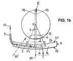
図1aおよび1bは、このような、眼科的視覚および追加的視覚を提供する眼鏡レンズの原理を示す図である。この眼鏡レンズは、挿入物2が内部に配置された基本レンズ1を有している。基本レンズ1は、透明且つ屈折性の材料から構成されている。この材料は、眼科分野において使用される任意の有機材料または鉱物性材料であってよい。基本レンズ1は、凸状の前面FAおよび凹状の後面FPを有している。これらの面FAおよび面FPは、それぞれ、曲率を有している。これらの各曲率と、基本レンズ1の屈折媒体の光の屈折率の値とにより、眼科的視覚のための、眼鏡レンズの、挿入物2の外部の光出力が決定される。この光出力は、装用者がレンズを通して見る様々な方向において、変動し得る。 FIGS. 1a and 1b illustrate the principle of a spectacle lens that provides such ophthalmic and additional vision. This spectacle lens has a basic lens 1 in which an
挿入物2は、基本レンズ1の面FAと面FPとの間に位置する比較的薄い光導体であってよい。挿入物2は、基本レンズ1とは異なる光反射性および/または屈折特性を有していてよく、詳細には示されていないソース3からの追加的光VSをもたらすために適した光反射性および/または屈折特性を有していてよい。こうして、光VSは、装用者の眼の方を向いた挿入物出力ウィンドウFSにもたらされる。挿入物2の構造は、本明細書の対象ではなく、当該対象について入手可能な他の文献が参照され得る。概して、基本レンズ1は、挿入物2と前面FAとの間に前部1a、および、挿入物2と後面FPとの間に後部1pを有していてよい。挿入物2はまた、基本レンズ1の区域内において、面FAおよび面FPにほぼ平行である特定の方向に横方向に制限されていてもよい。このような構成では、基本レンズ1の前部1aおよび後部1pは、挿入物2の周辺端部2bを越えてのびている。従って、基本レンズ1は、挿入物2のエッジ2bを超えてのびると共に、部分1aおよび1bを連続的に基本レンズ1の周辺端部Bに連結させる中間部1bを有している。基本レンズ1のエッジは、例えば、60mm(ミリメートル)の直径を有する円状であってよい。 The
図1bに図示されるように、Σとして示される追加的視覚の開口角は、挿入物2の出力ウィンドウFSによって制限される。その極は、レンズの背後の、装用者の眼10の回転の中心Oである。典型的には、開口Σは、ウィンドウFSの中心を通過する、追加的視覚の光軸のいずれか一方の側において、+/−15°(度)であってよい。開口Σの限界線の母線は、レンズの後面FPと交差している。このレンズの後面内には、2つの視覚である眼科的視覚および追加的視覚が重なり合う区域Zが規定されている。図1aおよび1bの構成では、眼科的視覚の光軸および追加的視覚の光軸は、全く同一であるが、これらが異なっていてもよい。 As illustrated in FIG. 1 b, the additional visual aperture angle, denoted as Σ, is limited by the output window FS of the
図1aおよび1bは、眼鏡レンズを、装用者が使用する位置において示す図である。従って、参照番号10で示される装用者の眼は、後面FP側の、レンズの背後に位置しているので、一方では、レンズの前方に位置する環境に起因する光VOを受け、他方では、挿入物2によってもたらされる光VSを受ける。これらの光VOおよび光VSの2つの光線は、それぞれ、眼科的視覚および追加的視覚に相当する。これらの光線は、それぞれ、瞳孔11を通過した後に、装用者の網膜12上に、眼科的画像および追加的画像を形成する。参照番号13は、装用者の瞳孔11を包囲する、装用者の虹彩を示している。装用者が視認する方向は、眼10の光軸に相当する。この光軸は、眼10が装用者の眼窩において回転する時に変動する各点において、眼鏡レンズの面FAおよび面FPと交差する。 1a and 1b show the spectacle lens in a position for use by the wearer. Therefore, the eye of the wearer indicated by
光VOが、レンズの2つの面FAおよび面FPを通過するならば、これら両方の面は、眼科的視覚に関するレンズの光学特性に寄与する。しかし、光VSは、面FAを通過しないので、この面FAは、レンズの、追加的視覚に関する光学特性に寄与しない。光VOと光VSとがこのように異なるため、これらの光は、レンズの後面FPを通過した後、同一の収束特性を示さない。このため、網膜上に形成される眼科的画像および追加的画像は、同時に明瞭にはならない。 If the light VO passes through the two surfaces FA and FP of the lens, both these surfaces contribute to the optical properties of the lens with respect to ophthalmic vision. However, since the light VS does not pass through the surface FA, this surface FA does not contribute to the optical properties of the lens with respect to additional vision. Since the light VO and the light VS are thus different, these lights do not show the same convergence characteristics after passing through the rear surface FP of the lens. For this reason, the ophthalmic image and the additional image formed on the retina are not simultaneously clear.
「眼科的視覚および追加的視覚の一方または他方に関するレンズの光学特性」という表現は、特に、装用者が視認する各方向についての、レンズの光出力値、非点収差値、光学的ひずみ値などを意味するものと理解されるべきである。 The expression “the optical properties of the lens with respect to one or the other of ophthalmic vision and additional vision” means, in particular, the light output value, astigmatism value, optical distortion value, etc. of the lens for each direction viewed by the wearer. Should be understood as meaning.
網膜12上の追加的画像と眼科的画像との間において焦点整合が異なることは、装用者の眼10の調節によって補償され得る。文献WO2008/003903号は、装用者が眼科的視覚から追加的視覚に切り替える場合の、装用者の調節作用の限度を紹介している。この調節作用の限度は、特に、装用者の年齢に依存している。しかし、特に視認方向が、眼鏡レンズおよび/または挿入物2の出力ウィンドウFSによって変動する場合でも、これら2つの眼科的画像および追加的画像は、光学収差を保持している。本発明において、「光学収差」という表現は、光出力または非点収差の、規定の値に対する偏差、または、他の任意の、特にゼルニケ多項式によって特徴付けられ得るより桁の大きい収差を意味するものと理解されたい。 The difference in focus alignment between the additional image on the retina 12 and the ophthalmic image can be compensated by adjustment of the wearer's
図2a〜2dおよび図3a〜3dは、本発明を実施せずに製造された、2つの眼科的視覚および追加的視覚を有する眼鏡レンズに関する。 FIGS. 2a-2d and FIGS. 3a-3d relate to spectacle lenses with two ophthalmic and additional visions made without practicing the present invention.
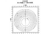
図2aおよび2bは、それぞれ、眼科的視覚の、第1の眼鏡レンズの平均光出力および非点収差を示す図である。この第1のレンズは、非点収差補正をしていない、−4.00ジオプトリーの近視補正処方に相当する。基本レンズ1の材料の屈折率は、1.60である。各図は、視認方向がレンズを通して変動する時の、眼鏡レンズの平均光出力の値または非点収差の値を示している。x軸およびy軸は、それぞれ、垂直面および水平面において、視認方向と基準方向との間の角度αおよび角度βを特定している。想定される基準方向は、眼鏡レンズの基準点を通過する。この基準点は、特に、レンズを眼鏡のフレームのハウジングに位置付けるために用いられる、取り付け点であり得る。これらの図の各曲線は、当該曲線上においてジオプトリーで示される、全く同一の平均光出力または非点収差の値に相当する視認方向と結びついている。図2aに示されるように、眼科的視覚の場合、レンズの周辺には、基準方向の場合に生成される規定の値に対して、−1.25ジオプトリーに達する負の平均光出力差が現れる(α=β=0)。この差は、レンズの前面FAの曲率が光学収差に適していないために生じる。なぜなら、この曲率は、追加的視覚モードにおいて装用者の調節作用を制限するように、低減されているからである。同じ理由から、図2bは、視認方向が、基準方向からレンズの周辺に向かって逸脱すると、非点収差が、著しく増大することを示している。 2a and 2b are diagrams showing the average light output and astigmatism of the first spectacle lens in ophthalmic vision, respectively. This first lens corresponds to a -4.00 diopter myopia correction prescription without astigmatism correction. The refractive index of the material of the basic lens 1 is 1.60. Each figure shows the average light output value or astigmatism value of the spectacle lens when the viewing direction varies through the lens. The x-axis and the y-axis specify an angle α and an angle β between the viewing direction and the reference direction in the vertical plane and the horizontal plane, respectively. The assumed reference direction passes through the reference point of the spectacle lens. This reference point can in particular be an attachment point used to position the lens in the housing of the spectacle frame. Each curve in these figures is associated with a viewing direction corresponding to exactly the same average light output or astigmatism value indicated in diopters on the curve. As shown in FIG. 2a, in the case of ophthalmic vision, a negative average light output difference appears at the periphery of the lens, reaching -1.25 diopters for the specified value generated for the reference direction. (Α = β = 0). This difference occurs because the curvature of the front FA of the lens is not suitable for optical aberration. This is because the curvature has been reduced to limit the wearer's accommodation in additional visual modes. For the same reason, FIG. 2b shows that astigmatism increases significantly when the viewing direction deviates from the reference direction towards the periphery of the lens.
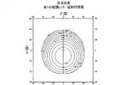
図2cおよび2dは、同じく、同一の第1の眼鏡レンズのために設定された平均光出力および非点収差を示す図であるが、追加的視覚の場合を示すものである。図2cは、特に、選択された調節作用が、基準方向用の平均光出力の値に従って、約−1.00ジオプトリーであることを示している。 Figures 2c and 2d are also diagrams showing the average light output and astigmatism set for the same first spectacle lens, but showing the case of additional vision. FIG. 2c shows in particular that the selected adjustment action is approximately −1.00 diopters according to the value of the average light output for the reference direction.
このような近視用の眼鏡レンズの場合、2つの視覚(図2aおよび2c)の、平均光出力差は、基準方向に対するレンズの周辺区域において、負である。従って、必要ならば、装用者がレンズを通して斜めに視る場合に、眼の調節をすることによって、補正することが可能である。 For such a myopic eyeglass lens, the average light output difference between the two visions (FIGS. 2a and 2c) is negative in the area around the lens relative to the reference direction. Therefore, if necessary, when the wearer views obliquely through the lens, it can be corrected by adjusting the eyes.
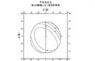
図3a〜3dは、それぞれ、図2a〜2dに相当し、2つの視覚を有する第2のレンズを示す図である。これは、+2.00ジオプトリー、−2.00ジオプトリー、および135°の遠視の処方に相当する。これらの値は、負の規約によるシリンダ値として表現される。基準方向(α=β=0)の平均光出力は、従って、約+1.00ジオプトリー(図3a)である。このような遠視の補正では、レンズの前面FAが不適切な曲率を有していると、レンズの周辺区域における平均光出力と、眼科的視覚では正である基準補正のための値との間に差が生じ得る。従って、これは、眼の調節機能に反し、そのため、結果として生じる眼科的制約は、極めて大きい。さらに、この追加的視覚の第2のレンズの調節作用は、約−2.25ジオプトリーである(図3aおよび3c)。 FIGS. 3a to 3d correspond to FIGS. 2a to 2d, respectively, and show a second lens having two visions. This corresponds to prescriptions of +2.00 diopters, -2.00 diopters, and 135 ° hyperopia. These values are expressed as cylinder values according to a negative convention. The average light output in the reference direction (α = β = 0) is therefore about +1.00 diopters (FIG. 3a). In such hyperopia correction, if the front FA of the lens has an inappropriate curvature, it is between the average light output in the surrounding area of the lens and the value for reference correction that is positive in ophthalmic vision. Differences can occur. This is therefore contrary to the eye's accommodation function, so the resulting ophthalmic constraints are very large. Furthermore, the additional visual second lens accommodation is approximately -2.25 diopters (FIGS. 3a and 3c).
従って、図2a〜2dおよび図3a〜3dは、これら2つのレンズの光学収差が、水平面および垂直面の両方において、眼科的視界および追加的視界を減少させることを示している。この視界の減少は、特に眼鏡フレーム内のレンズのハウジングの寸法が大きい場合に、特に眼科的視覚にとって、不利となる。また、追加的視界の減少は、広い出力ウィンドウを有する挿入物の使用を妨げる。 Thus, FIGS. 2a-2d and FIGS. 3a-3d show that the optical aberrations of these two lenses reduce ophthalmic and additional views in both the horizontal and vertical planes. This reduced field of view is disadvantageous, especially for ophthalmic vision, especially when the size of the housing of the lens in the spectacle frame is large. In addition, the reduced field of view prevents the use of inserts with a wide output window.
従って、本発明の目的は、装用者に両方の視覚を提供するように意図されると共に、上述の欠点が低減された、眼鏡レンズを提供することにある。 Accordingly, it is an object of the present invention to provide a spectacle lens that is intended to provide both vision to the wearer and has the aforementioned drawbacks reduced.
特に、本発明の一目的は、このような眼鏡レンズの視界、すなわち眼科的視界および追加的視界を増大させることにある。 In particular, it is an object of the present invention to increase the field of view of such spectacle lenses, ie ophthalmic field and additional field of view.
このため、本発明は、上述の少なくとも2つの種類の視覚を有する眼鏡レンズを製造する方法を提案する。この方法は、次の連続するステップを含む。
(1)レンズの装用者の眼科的処方を得るステップ、
(2)上記眼科的処方、および追加的画像の位置から、追加的視覚のための追加的処方を決定するステップ、
(3)上記ステップ(2)において決定された追加的処方に対応するレンズの後面用の少なくとも1つの曲率値を、追加的処方点において決定するステップ、
(4)上記ステップ(1)において得られた眼科的処方、および、上記ステップ(3)において決定されたレンズの後面の曲率値に応じて、レンズの前面用の少なくとも1つの曲率値を、眼科的処方点において決定するステップ、
(5)少なくとも、挿入物の出力ウィンドウに相当する上記後面の区域(Z)の内部において、レンズの後面の値を算出するステップであって、上記後面の区域が、上記ステップ(2)において決定された追加的処方に対応する追加的視覚用の補正を生成するように設計されたステップ、
(6)レンズの前面の値を算出するステップであって、レンズの後面が、上記ステップ(5)において算出された値を有している時に、レンズが、上記ステップ(1)において得られた眼科的処方に対応する眼科的視覚用の補正を生成するように設計されたステップ、および、
(7)各ステップ(5)および(6)においてそれぞれ算出された前面および後面用の値を有する、眼鏡レンズを製造するステップ。For this reason, the present invention proposes a method of manufacturing a spectacle lens having at least two types of vision as described above. The method includes the following successive steps.
(1) obtaining an ophthalmic prescription for the lens wearer;
(2) determining an additional prescription for additional vision from the ophthalmic prescription and the location of the additional image;
(3) determining at least one curvature value for the rear surface of the lens corresponding to the additional prescription determined in step (2) above at the additional prescription point;
(4) According to the ophthalmic prescription obtained in the step (1) and the curvature value of the rear surface of the lens determined in the step (3), at least one curvature value for the front surface of the lens is Determining at a prescription point,
(5) calculating a value of the rear surface of the lens at least inside the rear surface area (Z) corresponding to the output window of the insert, wherein the rear surface area is determined in the step (2); Steps designed to generate additional visual corrections corresponding to the added additional prescriptions,
(6) A step of calculating the value of the front surface of the lens, wherein the lens is obtained in step (1) when the rear surface of the lens has the value calculated in step (5). Steps designed to generate an ophthalmic vision correction corresponding to the ophthalmic prescription; and
(7) A step of manufacturing a spectacle lens having values for the front and rear surfaces calculated in the steps (5) and (6), respectively.
従って、本発明に係る眼鏡レンズは、眼科的視覚と追加的視覚とを同時に提供する。これらの視覚は、それぞれ、装用者がこれらの2つの視覚を同時且つ明確に知覚するように適合された光学特性を有している。換言すると、この眼鏡レンズは、眼科的視覚および追加的視覚用の、2つの眼科的出力値を有している。これらの値は、対応する各処方点を通過する視認方向について、装用者に適合される。 Therefore, the spectacle lens according to the present invention simultaneously provides ophthalmic vision and additional vision. Each of these sights has optical properties adapted to allow the wearer to perceive these two sights simultaneously and clearly. In other words, the spectacle lens has two ophthalmic output values for ophthalmic vision and additional vision. These values are adapted to the wearer for the viewing direction passing through each corresponding prescription point.
さらに、2つの視覚は、これらの処方点を通過する方向の場合だけでなく、これらの処方点の外部を通る視認方向の場合にも、明確に知覚される。換言すると、レンズは、眼科的視覚および追加的視覚の両方に、広い視界を提供する。特に、視界または追加的視覚は、挿入物の出力ウィンドウの全体を包含し得る。従って、これら2つの視覚の場合に装用者が得られる視覚の快適さは、強化される。 Furthermore, the two visions are clearly perceived not only in the direction of passing through these prescription points, but also in the direction of viewing through the exterior of these prescription points. In other words, the lens provides a wide field of view for both ophthalmic vision and additional vision. In particular, the field of view or additional vision may encompass the entire output window of the insert. Thus, the visual comfort that the wearer obtains in these two visual cases is enhanced.
有利に組み合わせ可能な、本発明に係る方法のステップ(5)および(6)の特定の形態によれば、一方では、眼鏡レンズの後面の値、および、他方では、眼鏡レンズの前面の値は、デジタル最適化によって算出可能である。 According to a particular form of steps (5) and (6) of the method according to the invention which can be advantageously combined, the value of the rear surface of the spectacle lens on the one hand and the value of the front surface of the spectacle lens on the other hand are It can be calculated by digital optimization.
本発明の一改良例によれば、ステップ(5)において、レンズの後面を最適化によって算出する場合、その算出は、後面の、挿入物の出力ウィンドウに相当する区域と、後面の残りの区域とにおいて、異なって実施され得る。この場合、後面の、挿入物の出力ウィンドウに相当する区域内の値は、追加的視覚のためのレンズの光学特性を最適化するために、再び決定される。しかし、後面の残りの区域内の値は、この改良例によれば、眼科的視覚のためのレンズの光学特性を最適化するために、決定される。このようにして製造される眼鏡レンズは、装用者に、眼科的視覚のための著しく穏やかな視界を提供する。 According to an improvement of the present invention, in step (5), when the rear surface of the lens is calculated by optimization, the calculation is performed on the area corresponding to the output window of the rear surface and the remaining area on the rear surface. And can be implemented differently. In this case, the value in the area corresponding to the output window of the rear face is again determined in order to optimize the optical properties of the lens for additional vision. However, the values in the remaining area of the rear surface are determined according to this refinement in order to optimize the optical properties of the lens for ophthalmic vision. The spectacle lens produced in this way provides the wearer with a significantly gentler field of view for ophthalmic vision.
本発明はまた、少なくとも2つの視覚、すなわち、眼科的視覚および追加的視覚を提供する眼鏡レンズを提案する。この眼鏡レンズは、従来技術から公知であるが、その2つの面、すなわち前面および後面が複雑な形状を有している点を特徴とする。 The present invention also proposes a spectacle lens that provides at least two visions, ophthalmic vision and additional vision. This spectacle lens is known from the prior art, but is characterized in that its two surfaces, namely the front and rear surfaces, have complex shapes.
このようなレンズは、本発明に係る方法を用いて、製造可能である。 Such a lens can be manufactured using the method according to the invention.
他の特定の特徴および本発明の利点は、以下の、添付の図面を参照した、限定しない実施形態の説明から明らかであろう。 Other particular features and advantages of the invention will be apparent from the following description of non-limiting embodiments, with reference to the accompanying drawings.
既に説明した図1aおよび図1bは、従来技術から公知の、2つの視覚を提供する眼鏡レンズを示す2つの図である。各図は、斜視図および上面図である。 FIG. 1a and FIG. 1b already described are two views showing a spectacle lens providing two visions known from the prior art. Each figure is a perspective view and a top view.
既に説明した図2aおよび図2bは、それぞれ、図1aおよび図1bに係る第1の眼鏡レンズ、且つ、眼科的視覚の、平均光出力および非点収差を示す図である。 2a and 2b which have already been described are diagrams showing the first spectacle lens according to FIGS. 1a and 1b and the average light output and astigmatism of ophthalmologic vision, respectively.
既に説明した図2cおよび図2dは、それぞれ、図2aおよび図2bの第1の眼鏡レンズ、且つ、追加的視覚の、平均光出力および非点収差を示す図である。 2c and 2d already described are diagrams showing the first spectacle lens of FIGS. 2a and 2b, respectively, and additional visual average light output and astigmatism, respectively.
既に説明した図3a〜3dは、それぞれ、図2a〜2dに対応する図であり、図1aおよび図1bに係る第2の眼鏡レンズを示す図である。 FIGS. 3a to 3d already described are views corresponding to FIGS. 2a to 2d, respectively, and show the second spectacle lens according to FIGS. 1a and 1b.
図4は、本発明に係る方法のステップを示すブロック図である。 FIG. 4 is a block diagram showing the steps of the method according to the invention.
図5は、本発明の一改良例の、補完的なブロック図である。 FIG. 5 is a complementary block diagram of an improvement of the present invention.
図6a〜6dおよび図7a〜7dは、それぞれ、本発明を用いた、図2a〜2dおよび図3a〜3bに対応する。 Figures 6a-6d and 7a-7d correspond to Figures 2a-2d and 3a-3b, respectively, using the present invention.
次の説明では、眼科分野の一般的知識は、詳細には検討しない。このことは、特に、処方点の外部の光学収差を低減するように構成されたチェルニングの基本値にも、適用される。同じことが、長年にわたって一般的に用いられてきた、眼科的レンズを最適化するデジタル的方法にも当てはまる。また、眼鏡レンズを製造するために用いられる機械的加工方法にも、同じことが当てはまる。 In the following description, general knowledge in the field of ophthalmology is not considered in detail. This applies in particular to the basic values of chelning that are configured to reduce optical aberrations outside the prescription point. The same applies to digital methods for optimizing ophthalmic lenses that have been commonly used for many years. The same applies to the mechanical processing methods used to manufacture spectacle lenses.
本発明は、図1aおよび図1bに係る眼鏡レンズを、最初に、後面FPの形状を算出して、その後、前面FAの形状を算出することによって、製造するものである。従って、最終的なレンズは、挿入物2が組み込まれた基本レンズ1の荒削りを機械加工することによって、製造される。算出されたこれらの各面の複雑な形状に応じて、この素材の2つの面FPおよびFAを、機械加工する。公知のように、1つの面は、その各点において、2つの曲率値を有している。これら2つの曲率値は、当該各点を貫通する、互いに垂直方向における、各最大値および最小値である。「複雑な形状の面」という表現は、レンズの面の少なくとも1つの曲率値が、この面の様々な点の間で、連続的に変動するレンズの面を意味するものと理解すべきである。従って、複雑な面とは、この面の区域内において、階段状または不連続性の曲率を有しているということではない。視認方向における、眼鏡レンズの面の、平均光出力への寄与は、次の式によって、得られる。 In the present invention, the spectacle lens according to FIGS. 1 a and 1 b is manufactured by first calculating the shape of the rear surface FP and then calculating the shape of the front surface FA. The final lens is thus manufactured by machining the roughing of the basic lens 1 in which the
PA=(n−1)×(CAmax+CAmin)/2 (1a)
PP=(1−n)×(CPmax+CPmin)/2 (1b)
ここで、PA/PPは、前面FA/後面FPの寄与を示し、nは、この面のレベルにおいて、基本レンズ1を構成する屈折媒体の屈折率であり、CAmax/CPmaxおよびCAmin/CPminは、面FA/FPが視認方向と交差する点における、面FA/FPの最大および最小曲率である。PA = (n−1) × (CAmax + CAmin ) / 2 (1a)
PP = (1−n) × (CPmax + CPmin ) / 2 (1b)
Here, PA / PP indicates the contribution of the front FA / rear surface FP, and n is the refractive index of the refractive medium constituting the basic lens 1 at the level of this surface, and CAmax / CPmax and CAmin /CPmin is the maximum and minimum curvatures of surface FA / FP at the point where surface FA / FP intersects the viewing direction.
次に、眼科的処方点における、眼鏡レンズの前面FAの曲率を決定するまでの、本発明に係る方法の最初の段階を説明する。当業者の専門用語では、この最初の段階は、基本カッティングと呼ばれている。この段階は、レンズの素材を、眼科的処方点において可変の曲率を有する様々な素材から選択するために用いられる。通常、素材は、装用者のために設定された眼科的処方に基づいて、眼鏡レンズの光学収差を低減することと、レンズの美的外観のために面FAの曲率を制限することとの間の妥協点に応じて、選択される。 Next, the first step of the method according to the present invention will be described until the curvature of the front FA of the spectacle lens at the ophthalmic prescription point is determined. In the jargon of those skilled in the art, this first step is called basic cutting. This stage is used to select the lens material from a variety of materials with variable curvature at the ophthalmic prescription point. Typically, the material is between reducing the optical aberrations of the spectacle lens based on the ophthalmic prescription set for the wearer and limiting the curvature of the surface FA for the aesthetic appearance of the lens. Selected according to compromise.
本発明では、この基本カッティング段階は、さらに2つの目的を有している。一方の目的は、前面FAの曲率を、基本レンズを過度に厚くせずに、挿入物2を基本レンズ1の内部に配置することと両立させなければならない点である。また他方の目的は、装用者の視認が眼科的画像と追加的画像との間を遷移する間に、良好な視覚的快適さを同時に提供する調節作用を、実現しなければならない点である。 In the present invention, this basic cutting stage has two further purposes. One purpose is that the curvature of the front FA must be compatible with placing the
最終的に製造される眼鏡レンズでは、眼科的補正は、2つの面FAおよび面FPの形状によってもたらされる。しかし、レンズによって生成される、追加的補正と呼ばれる、追加的視覚のための補正は、後面FPにのみ生成される。このため、装用者の眼は、眼科的視覚から眼鏡レンズを介して追加的視覚まで切り替えられる時に、調節を行う。この調節のレベルは、調節作用と呼ばれる。調節作用は、基本的に、レンズの前面FAの形状、および、挿入物2によって生成される追加的画像の位置によってもたらされる。この追加的画像が、レンズの前に、遠く離れて位置する仮想の画像であり、眼科的視覚のためのレンズの平均光出力が、レンズの2つの面FAおよび面FPの各代数寄与分を加算することによって、概算可能であることが認められるならば、調節作用は、眼科的視覚用の眼鏡レンズの平均光出力から、眼鏡レンズの後面FPの代数寄与分を減算することによって、概算可能である。 In the final manufactured spectacle lens, ophthalmic correction is provided by the shape of the two surfaces FA and FP. However, the correction for additional vision, called additional correction, generated by the lens is generated only on the rear surface FP. For this reason, the wearer's eyes make adjustments when they switch from ophthalmic vision to additional vision via a spectacle lens. This level of regulation is called regulation. The accommodation is basically brought about by the shape of the front face FA of the lens and the position of the additional image produced by the
最初に、レンズの装用者の屈折異常に応じて、該装用者に処方された眼科的補正を得る。この眼科的補正は、一般的な方法で測定可能であり、装用者の眼鏡レンズを通した眼科的視覚に関する。この眼科的補正は、通常、平均光出力および非点収差補正を決定する幾つかの値を含む。眼科的補正は、眼科的処方点と呼ばれる、レンズの前面の一点のために設定される。この眼科的処方点は、概して、装用者の真っ直ぐ前方の視認方向に相当する。この場合、眼科的処方点は、眼鏡のフレームのハウジング内にレンズを位置決めするために用いられる取り付け点と組み合わせることが可能である。本発明では、眼科的処方点はまた、眼科的視界の中心である、レンズを通した視認方向を規定する。 First, an ophthalmic correction prescribed for the wearer is obtained in accordance with the refractive error of the wearer of the lens. This ophthalmic correction can be measured in a general manner and relates to ophthalmic vision through the wearer's spectacle lens. This ophthalmic correction typically includes several values that determine the average light output and astigmatism correction. Ophthalmic correction is set for a point on the front of the lens, called the ophthalmic prescription point. This ophthalmic prescription point generally corresponds to the wearer's straight forward viewing direction. In this case, the ophthalmic prescription point can be combined with the attachment point used to position the lens within the housing of the spectacle frame. In the present invention, the ophthalmic prescription point also defines the viewing direction through the lens, which is the center of the ophthalmic field of view.
その後、調節作用のための値を、特に装用者の年齢に応じて設定する。この値は、概して、負でなければならない。これは、挿入物2の出力ウィンドウFSのすぐ後ろに、追加的光VSによって生成される追加的画像の位置に依存している。その後、装用者にとっての追加的視覚用の処方を推定する。これは、追加的処方と呼ばれる。挿入物2によって生成された追加的画像が、眼鏡レンズの前方に遠く離れて、典型的には2m(メートル)よりも遠く離れて位置している時は、追加的処方は、眼科的処方と調節作用との合計に等しい。 Thereafter, a value for the regulating action is set, in particular according to the age of the wearer. This value should generally be negative. This depends on the position of the additional image produced by the additional light VS immediately behind the output window FS of the
好ましくは、追加的処方は、装用者の調節作用が、絶対値として2.25ジオプトリーよりも低いように、決定される。 Preferably, the additional prescription is determined such that the adjustment effect of the wearer is lower than 2.25 diopters as an absolute value.
追加的処方の非点収差値は、眼科的処方の非点収差値と同一であってよい。 The astigmatism value of the additional prescription may be the same as the astigmatism value of the ophthalmic prescription.
その後、レンズの後面FPの曲率を、特に追加的処方から決定する。従って、これは、追加的処方点と呼ばれる面FPの基準点のために決定される。この追加的処方点は、挿入物2の出力面FSの中心を貫通する、装用者の視認方向に相当し得る。一般に、追加的処方点は、眼科的処方点と異なっていてよい。これは、特に、挿入物2の出力ウィンドウFSが、レンズの取り付け用交差点に対して、眼鏡レンズの上面に横方向におよび/または該上面に向かって、ずれて配置されている場合である。第1の概算として、次の関係式を用いて、追加的処方点における、面FPの曲率CPを算出することが可能である。Thereafter, the curvature of the rear surface FP of the lens is determined in particular from the additional prescription. This is therefore determined for a reference point of the plane FP called the additional prescription point. This additional prescription point may correspond to the wearer's viewing direction through the center of the output face FS of the
CP=PS/(1−n) (2)
ここで、PSは追加的処方である。CPの値は、負であり、これは、レンズの面FPが凹状であることを意味している。実際には、眼科的処方が非点収差補正を含む場合、関係式(1)を、該処方によって示される2つの各垂直方向に適用して、2つの曲率値、すなわち最大曲率値および最小曲率値を得る。CP = PS / (1-n) (2)
Here, PS is an additional prescription. The value of CP is negative, which means that the plane FP of the lens is concave. In practice, if the ophthalmic prescription includes astigmatism correction, relation (1) is applied to each of the two vertical directions indicated by the prescription to obtain two curvature values, namely a maximum curvature value and a minimum curvature value. Get the value.
眼科的処方点におけるレンズの前面FAの曲率CAは、例えば次の関係式を用いることによって、決定することが可能である。Curvature CA of the lens in front FA in ophthalmic formulations point, for example, by using the following relationship can be determined.
CA=PO/(n−1)+CP (3)
ここで、POは、最初に得られた装用者のための眼科的処方である。通常の実務によれば、非点収差補正は、後面FPを介してのみ導入され得るので、前面FAは、追加的処方点において球状である。面FAの基本値Bは、その後、次の関係式によって求められる。CA = PO / (n−1) + CP (3)
Here, PO is the first ophthalmic prescription for the wearer. According to normal practice, astigmatism correction can only be introduced via the rear surface FP, so the front FA is spherical at the additional prescription point. Thereafter, the basic value B of the surface FA is obtained by the following relational expression.
B=(n−1)×CA (4)
好ましくは、この基本値Bは、屈折媒体の屈折率nが1.60であるように設定されている場合、2.25ジオプトリー以下である。このように、眼鏡レンズの面FAの曲率は、良好な美的外観を保持しながら、ほとんどの挿入物2の形状と両立し得る。さらに、装用者の調節作用が、同時に制限されるので、装用者は、眼科的視覚から追加的視覚に快適に切り替えることができる。B = (n−1) × CA (4)
Preferably, this basic value B is 2.25 diopters or less when the refractive index n of the refractive medium is set to 1.60. Thus, the curvature of the face FA of the spectacle lens can be compatible with most of the shape of the
こうして得られた、基本レンズ1の前面FAのための基本値は、通常、レンズの光学収差を低減するために適した値ではない。特に、各曲率値CAおよびCPを有する球状の面FAおよび面FPを備えるレンズは、眼科的処方および追加的処方について、それぞれの処方点を貫通しない視認方向の場合に、光出力における著しい偏差を有していることになる。このため、本発明に係る方法の第2の段階において、追加的視覚の光学収差を低減するために、レンズの後面FPを算出する。その後、本方法の第3の段階において、眼科的視覚の光学収差を低減するために、前面FAを算出する。これら2つの段階の様々なステップは、図4に示されている。The basic value for the front FA of the basic lens 1 obtained in this way is usually not a value suitable for reducing the optical aberration of the lens. In particular, lenses with spherical surfaces FA and FP with respective curvature values CA and CP have a significant light output power for ophthalmic and additional prescriptions in the viewing direction that does not penetrate the respective prescription points. It will have a deviation. Thus, in the second stage of the method according to the invention, the rear surface FP of the lens is calculated in order to reduce additional visual optical aberrations. Thereafter, in a third stage of the method, the front FA is calculated to reduce optical aberrations in ophthalmic vision. The various steps of these two stages are shown in FIG.
本方法の第2の段階(デジタル最適化を含む場合)は、第1のターゲット仮想レンズを構成することと共に始まる。第1のターゲット仮想レンズは、追加的処方に相当する公知のレンズであり、特に低減された光学収差を示すので参照されるものである。特に、その平均光出力は、眼科的処方点を貫通しない視認方向のための処方値については、ほとんど変動しない。同様に、第1のターゲット仮想レンズは、処方された値に近い任意の点において、非点収差値(非点収差軸の偏角および方向)を有している。第1のターゲット仮想レンズの他の光学収差も、低い偏角を有している。 The second stage of the method (if including digital optimization) begins with constructing the first target virtual lens. The first target virtual lens is a known lens corresponding to an additional prescription and is particularly referred to because it exhibits reduced optical aberrations. In particular, the average light output varies little for prescription values for viewing directions that do not penetrate ophthalmic prescription points. Similarly, the first target virtual lens has an astigmatism value (a declination and direction of the astigmatism axis) at an arbitrary point close to the prescribed value. Other optical aberrations of the first target virtual lens also have a low declination.
従って、第1のターゲット仮想レンズは、基本レンズ1の屈折媒体から構成されていると共に、
−追加的処方点において第1の基本値を有する仮想前面であって、上記第1の基本値は、追加的処方に関する追加的視覚の光学収差を低減するように選択されている、仮想前面と、
−上記第1のターゲット仮想レンズの上記仮想前面と共同して、追加的処方点において、追加的処方に適合する追加的視覚の補正を生成するように設計されている仮想後面と、を備えていてよい。Therefore, the first target virtual lens is composed of the refractive medium of the basic lens 1, and
A virtual front surface having a first base value at an additional prescription point, wherein the first base value is selected to reduce additional visual optical aberrations for the additional prescription; ,
A virtual rear surface designed to produce, at an additional prescription point, an additional visual correction adapted to the additional prescription in cooperation with the virtual front surface of the first target virtual lens; It's okay.
例えば、第1のターゲット仮想レンズの前面は、追加的処方に関連するチェルニングの基本値を有していてよい。そのため、その後面は、均一な曲率を有する球状または円環形であってよい。この均一な曲率により、追加的光のための、追加的処方に対応する光学補正が生成される。 For example, the front surface of the first target virtual lens may have a basic value of chelning associated with the additional prescription. Therefore, the rear surface may be spherical or annular with a uniform curvature. This uniform curvature produces an optical correction corresponding to the additional prescription for the additional light.
そして、第1のテスト仮想レンズを構成する。第1のテスト仮想レンズ自体は、
−挿入物2に従って規定された仮想前面、
−挿入物2自体、
−屈折性材料の後部1p、および、
−可変の複雑な後面を備えている。Then, the first test virtual lens is configured. The first test virtual lens itself is
-A virtual front defined according to the
The
The rear part 1p of the refractive material, and
-It has a variable and complex rear surface.
第1のテスト仮想レンズの前面は、挿入物2の平坦または曲線の形状、その厚み、その屈折特性、および、追加的画像の位置に応じて、様々に決定され得る。これは、挿入物2によってもたらされると共に屈折性材料の部分1pに伝播される光線によって生成される追加的画像の位置を考慮するように決定される。 The front surface of the first test virtual lens can be variously determined depending on the flat or curved shape of the
第1のテスト仮想レンズの後面は、初期状態では、該後面の任意の点、少なくとも挿入物2の出力ウィンドウFSに相当する区域Z上において、追加的処方点のために上記において決定された1つまたは複数の曲率値を有していてよい。この場合、第1のテスト仮想レンズは、少なくとも区域Z内において均一な曲率を有している。 The posterior surface of the first test virtual lens is initially determined for an additional prescription point at any point on the posterior surface, at least on the zone Z corresponding to the output window FS of the
その後、第1のテスト仮想レンズおよび第1のターゲット仮想レンズが、少なくとも区域Zの内部においてほぼ等しい光学特性を有するように、第1の最適化を行う。この第1の最適化の間に、第1のテスト仮想レンズの前面を設定する。この最適化は、公知のように、第1のターゲット仮想レンズの光学特性と第1のテスト仮想レンズの光学特性との間の差を数値で表すメリット関数の値を、これらの仮想レンズのために規定されたメッシュ点において低減することによって実行可能である。最適化の結果は、メッシュ点における、第1のテスト仮想レンズの後面の値から構成される。これらの値は、その後、眼鏡レンズの後面FPに割当てられ得る。必要ならば、これらの値を、本方法のこの時点で、変換してもよい。例えば、第1のテスト仮想レンズの後面の値は曲率値であってよく、これらは眼鏡レンズのサジタル値に変換される。こうして決定されたレンズの後面FPは、複雑な形状を有している。 Thereafter, a first optimization is performed so that the first test virtual lens and the first target virtual lens have approximately equal optical properties at least within the zone Z. During this first optimization, the front face of the first test virtual lens is set. As is known in the art, this optimization provides a value for the merit function that represents the difference between the optical properties of the first target virtual lens and the optical properties of the first test virtual lens in numerical values for these virtual lenses. This can be done by reducing the mesh points defined in The optimization result consists of the value of the back surface of the first test virtual lens at the mesh point. These values can then be assigned to the rear surface FP of the spectacle lens. If necessary, these values may be converted at this point in the method. For example, the value of the rear surface of the first test virtual lens may be a curvature value, which is converted to a sagittal value of the spectacle lens. The rear surface FP of the lens thus determined has a complicated shape.
必要ならば、その後、眼鏡レンズの後面FPの値を、本方法のさらなるステップの間に、調節してもよい。この調節は、挿入物2と眼鏡レンズの面FPとの間に縁部を提供することを意図した、面FAと面FPとの間の距離の第1の変更を補償することが可能である。この縁部は、挿入物2の後面の中心点と眼鏡レンズの面FPとの間に位置していてよい。公知のように、このような調節は、面FPの値に円環体の成分を加えることである。 If necessary, the value of the rear face FP of the spectacle lens may then be adjusted during further steps of the method. This adjustment can compensate for a first change in the distance between the face FA and the face FP, which is intended to provide an edge between the
本発明の一改良例によれば、眼鏡レンズの後面FPは、上述の方法で、挿入物2の出力ウィンドウFSに相当する区域Zにおいてのみ、算出可能である。 According to an improvement of the invention, the rear surface FP of the spectacle lens can be calculated only in the zone Z corresponding to the output window FS of the
この改良例は、眼科的視覚および追加的視覚の2つの各光軸が別々である場合に、特に有効である。図1aでは、参照記号VOおよびVO’は、それぞれ、2つの眼科的光線を示している。第1の光線は、挿入物2を貫通し、第2の光線は、区域Zの外部を通る。本改良例は、追加的視覚の光線VSの場合、および眼科的視覚の光線VO’の場合の、眼鏡レンズの後面FPを算出することを可能にする。 This improvement is particularly effective when the two optical axes of ophthalmic vision and additional vision are separate. In FIG. 1a, the reference symbols VO and VO 'each indicate two ophthalmic rays. The first ray passes through the
従って、上述の第1の最適化は、区域Zの内部に限定される。区域Zが後面FPよりも小さいならば、第1の最適化は、当該区域内の光学収差を大幅に低減することを実現可能である。 Thus, the first optimization described above is limited to the interior of zone Z. If the zone Z is smaller than the rear surface FP, the first optimization can be realized to significantly reduce the optical aberrations in the zone.
この場合、任意により、第2の最適化を行うことによって、後面FPを、区域Zの外部において算出し、眼科的視覚のための光学収差を低減することが可能である。 In this case, optionally, by performing the second optimization, the rear surface FP can be calculated outside the zone Z to reduce optical aberrations for ophthalmic vision.
このために、第2のターゲット仮想レンズを構成する。この第2のターゲット仮想レンズは、屈折媒体から構成されると共に、
−眼科的処方点において第2の基本値を有する仮想前面であって、上記第2の基本値は、眼科的処方に関する眼科的視覚の光学収差を低減するように選択された仮想前面と、
−上記第2のターゲット仮想レンズの仮想前面と共同して、眼科的処方点において、眼科的処方に適合した眼科的視覚の補正を生成するように設計された仮想後面と、を備えている。For this purpose, a second target virtual lens is constructed. The second target virtual lens is composed of a refractive medium,
A virtual front surface having a second basic value at an ophthalmic prescription point, wherein the second basic value is selected to reduce optical aberrations of ophthalmic vision for the ophthalmic prescription;
-In cooperation with a virtual front surface of the second target virtual lens, a virtual posterior surface designed to generate an ophthalmic vision correction adapted to the ophthalmic prescription at an ophthalmic prescription point.
換言すると、第2のターゲット仮想レンズは、眼科的処方に対応する基準レンズである。例えば、その前面は、この眼科的処方に関連するチェルニングの基本値を有していてよい。従って、その後面は、均一な曲率を有する球状または円環形であってよい。この均一な曲率により、眼科的光のための、眼科的処方に対応する補正が生成される。 In other words, the second target virtual lens is a reference lens corresponding to an ophthalmic prescription. For example, the front surface may have a base value of chelning associated with this ophthalmic prescription. Thus, the rear surface may be spherical or toroidal with a uniform curvature. This uniform curvature produces a correction corresponding to the ophthalmic prescription for ophthalmic light.
区域Zの外部において規定される第2のテスト仮想レンズ自体は、
−予め規定された曲率値を、眼科的処方点において有する仮想前面、
−屈折媒体の前部1a、
−屈折媒体の中間部1b、または挿入物2、
−屈折媒体の後部1p、および、
−可変の複雑な後面を備える。The second test virtual lens itself, defined outside the zone Z, is
A virtual front surface having a predefined curvature value at the ophthalmic prescription point;
The front 1a of the refractive medium,
The intermediate part 1b of the refractive medium, or the
The rear part 1p of the refractive medium, and
-With variable and complex rear surface.
第2のテスト仮想レンズの前面は、その範囲全体を通して均一である曲率を有していてよい。この曲率は、第2のテスト仮想レンズの最適化の間に設定される。 The front surface of the second test virtual lens may have a curvature that is uniform throughout its range. This curvature is set during the optimization of the second test virtual lens.
必要ならば、第2のテスト仮想レンズの後面も、初期状態では、最適化の前、且つ、区域Zの外部において、均一な曲率値を有していてもよい。これらの値は、第2のテスト仮想レンズが、眼科的処方点において、眼科的処方に対応する眼科的視覚のための光学補正を生成するように決定され得る。 If necessary, the rear surface of the second test virtual lens may also have a uniform curvature value in the initial state before optimization and outside the zone Z. These values may be determined such that the second test virtual lens generates an optical correction for ophthalmic vision corresponding to the ophthalmic prescription at the ophthalmic prescription point.
第2のテスト仮想レンズに用いられる最適化アルゴリズムは、事前に第1のテスト仮想レンズのために用いられたアルゴリズムと同様であってよい。 The optimization algorithm used for the second test virtual lens may be similar to the algorithm previously used for the first test virtual lens.
図5は、本発明の改良例である、このさらなる最適化を示す図である。第2のテスト仮想レンズは、区域Zの外部において、第2のターゲット仮想レンズの光学特性にほぼ等しい光学特性を有するように、最適化される。区域Zの外部では、その後、第2のテスト仮想レンズの後面のために最適化された値から、眼鏡レンズの後面の値を得る。この場合、眼鏡レンズの後面FPは、区域Zの内部の第1の最適化により得られた値、および区域Zの外部の第2の最適化により得られた値から再構成される。必要ならば、区域Zの限界線における後面FPの連続性の制約を、第2の最適化に導入してもよい。 FIG. 5 illustrates this further optimization, which is an improvement of the present invention. The second test virtual lens is optimized to have optical properties that are approximately equal to the optical properties of the second target virtual lens outside of the zone Z. Outside the zone Z, the value of the rear surface of the spectacle lens is then obtained from the value optimized for the rear surface of the second test virtual lens. In this case, the rear surface FP of the spectacle lens is reconstructed from the value obtained by the first optimization inside the zone Z and the value obtained by the second optimization outside the zone Z. If necessary, a continuity constraint on the rear face FP at the limit line of the zone Z may be introduced into the second optimization.
第1の最適化が、区域Zの内部に制限され、上述の第2の最適化が行われていない場合、眼鏡レンズの後面FPは、第1の最適化により得られた区域Z内の値を、第1のターゲット仮想レンズの後面の区域Zの外部の初期値と組み合わせる。 When the first optimization is limited to the inside of the zone Z and the above-described second optimization is not performed, the rear surface FP of the spectacle lens is a value in the zone Z obtained by the first optimization. Is combined with the initial value outside the zone Z on the rear surface of the first target virtual lens.
本方法の第3の段階では、最終レンズの前面FAを算出して、装用者の眼科的視覚の光学収差を最少化する。再び図4を参照すると、基本レンズ1の屈折媒体から構成される第3のターゲット仮想レンズを新たに構成する。この第3のターゲット仮想レンズは、
−眼科的処方点において第3の基本値を有する仮想前面であって、上記第3の基本値は、眼科的処方に関する眼科的視覚の光学収差を低減するように選択された仮想前面と、
−上記第3のターゲット仮想レンズの仮想前面と共同して、眼科的処方点において、眼科的処方に適合した眼科的視覚の補正を生成するように設計された仮想後面と、を備えている。In the third stage of the method, the front FA of the final lens is calculated to minimize the optical aberrations of the wearer's ophthalmic vision. Referring to FIG. 4 again, a third target virtual lens composed of the refractive medium of the basic lens 1 is newly constructed. This third target virtual lens is
A virtual front surface having a third basic value at an ophthalmic prescription point, wherein the third basic value is selected to reduce optical aberrations of ophthalmic vision for the ophthalmic prescription;
-In cooperation with the virtual front surface of the third target virtual lens, a virtual rear surface designed to generate an ophthalmic vision correction adapted to the ophthalmic prescription at the ophthalmic prescription point.
従って、第3のターゲット仮想レンズは、上述の改良例において生成された第2のターゲット仮想レンズと同一であってよい。 Therefore, the third target virtual lens may be the same as the second target virtual lens generated in the above-described improved example.
第3のテスト仮想レンズは、
−可変の複雑な前面、
−屈折媒体の前部1a、
−関連する光線が挿入物2を貫通しているか否かに応じて、屈折媒体の中間部1bまたは挿入物2、
−屈折媒体の後部1p、および、
−本方法の第2の段階が完了した時に、眼鏡レンズのために得られた後面、を備えている。The third test virtual lens is
-Variable complex front,
The front 1a of the refractive medium,
The intermediate part 1b of the refractive medium or the
The rear part 1p of the refractive medium, and
A rear surface obtained for the spectacle lens when the second stage of the method is completed.
第3のテスト仮想レンズの前部はさらに、最適化の前、且つ、当該前面の任意の点において、事前に眼科的処方点のために決定された曲率値を有していてよい。 The front portion of the third test virtual lens may further have a curvature value that has been determined in advance for the ophthalmic prescription point prior to optimization and at any point on the front surface.
その後、第3のテスト仮想レンズおよび第3のターゲット仮想レンズが、ほぼ等しい光学特性を有するように、最後の最適化を行う。この最後の最適化は、第1の最適化のアルゴリズムと同様のアルゴリズムを用いてもよい。しかし、ここでは、第3のテスト仮想レンズの後面は固定されており、前面は可変である。さらに、挿入物2または屈折媒体の中間部1bは、関連する光線が挿入物を貫通するか否か(図1bの光線VOか、光線VO’か)に応じて、考慮される。 Thereafter, a final optimization is performed so that the third test virtual lens and the third target virtual lens have approximately equal optical properties. This last optimization may use an algorithm similar to that of the first optimization. However, here, the rear surface of the third test virtual lens is fixed, and the front surface is variable. Furthermore, the
最適化の最後では、第3のテスト仮想レンズの前面のために得られた値を、眼鏡レンズの前面FAに割当てる。必要ならば、これらの値を、この点において、変換してもよい。例えば、第3のテスト仮想レンズの前面の値は、曲率値であってよく、これらは、同じ面のサジタル値に変換される。概して、この方法で算出された眼鏡レンズの前面FAもまた、複雑な形状を有している。 At the end of the optimization, the value obtained for the front face of the third test virtual lens is assigned to the front face FA of the spectacle lens. If necessary, these values may be converted at this point. For example, the value of the front surface of the third test virtual lens may be a curvature value, which is converted to a sagittal value of the same surface. In general, the front face FA of the spectacle lens calculated by this method also has a complicated shape.
必要ならば、こうして得られた眼鏡レンズの前面のための値は、本方法のこの時点において、すなわち、さらなるステップの間に、調節可能である。このような調節は、面FAと面FPとの間の距離の第2の変更を補償することが可能である。このようにして、挿入物2のエッジ2bと面FAとの間に、所定の縁部を導入することが可能である。このような調節は、本方法の第3の段階において面FAのために算出された曲率に、円環体の成分を加えることである。 If necessary, the value for the front surface of the spectacle lens thus obtained can be adjusted at this point of the method, ie during further steps. Such an adjustment can compensate for a second change in the distance between the face FA and the face FP. In this way, it is possible to introduce a predetermined edge between the edge 2b of the
本方法の最後の第4の段階では、挿入物2が組み込まれた基本レンズ1の素材を機械加工することによって、眼鏡レンズを製造する。この素材は、面FPおよび面FAの両方において機械加工される。面FPは、本方法の第2の段階において算出された後面に応じて機械加工され、面FAは、第3の段階において算出された前面に応じて機械加工される。好ましくは、この機械加工は、算出された値に基づき、数値的に制御されている。 In the last fourth stage of the method, a spectacle lens is produced by machining the material of the basic lens 1 in which the
簡略化するため(しかし、決して限定を加えることを目的とするためではない)、添付の図面の全てのレンズでは、追加的処方点は、眼科的処方点と同じになるように選択されている。 For simplicity (but not for the purpose of limiting in any way), for all lenses in the attached drawings, the additional prescription point is chosen to be the same as the ophthalmic prescription point .
図6a〜6dは、第3のレンズと呼ばれる、本発明に従って製造されたレンズを示す図である。このレンズは、図2a〜2dの第1のレンズと同じ眼科的処方に対応する。図6aおよび図6bは、それぞれ、眼科的視覚の、平均光出力および非点収差に関し、図6cおよび6dは、それぞれ、追加的視覚の、平均光出力および非点収差に関する。図6aによれば、眼科的視覚の光出力は、眼科的処方点について、全レンズを通して、0.5ジオプトリーよりも少ないばらつきを示している。比較すると、第1のレンズ(図2a)では、眼科的処方点と水平面におけるレンズの周辺との間におけるこのばらつきは、絶対値としての1.0ジオプトリーよりも大きい。同時に、図2bと図6bとの比較は、水平面における眼科的視界の幅が、およそ、第1のレンズ(図2b)の+/−26°から、第3のレンズ(図6b)の+/−37°まで変化していることを示している。この視界の幅は、0.5ジオプトリー以下である無意識の非点収差に相当する。眼科的視覚の第1のレンズの非点収差(図2b)は、水平面におけるレンズの周辺において、2.0ジオプトリーを超えているが、第3のレンズ(図6b)では、非点収差は、0.75ジオプトリーよりも少なく制限されている。図2cおよび図6cは、本発明が、追加的視覚の光出力のばらつきを大幅に低減可能である点を示している。すなわち、このばらつきは、第1のレンズでは、水平面における絶対値としての1.0ジオプトリーよりも大きい(図2c)が、これらは、第3のレンズでは、0.5ジオプトリーよりも少ない(図6c)。最終的に、非点収差に関する図2dおよび図6dによれば、さらなる視界は、本発明を用いずに製造された第1のレンズの+/−21°から、本発明を用いて製造された第3のレンズの+/−25°まで増大される。同時に、本発明は、追加的視覚の場合の、レンズの周辺の水平面における非点収差を、2.0ジオプトリー(図2d)から1.0ジオプトリー(図6d)まで低減することを可能にした。さらに、第1のレンズおよび第3のレンズは、調節作用の場合に、同じ値を有している。 Figures 6a to 6d show a lens made in accordance with the present invention, called the third lens. This lens corresponds to the same ophthalmic prescription as the first lens of FIGS. 6a and 6b relate to ophthalmic visual average light output and astigmatism, respectively, and FIGS. 6c and 6d relate to additional visual average light output and astigmatism, respectively. According to FIG. 6a, the ophthalmic visual light output shows less than 0.5 diopters variation across the entire lens for the ophthalmic prescription point. In comparison, for the first lens (FIG. 2a), this variation between the ophthalmic prescription point and the periphery of the lens in the horizontal plane is greater than 1.0 diopters as an absolute value. At the same time, a comparison between FIG. 2b and FIG. 6b shows that the width of the ophthalmic field of view in the horizontal plane is approximately +/− 26 ° of the first lens (FIG. 2b) and +/− of the third lens (FIG. 6b). It shows a change to -37 °. This field of view corresponds to unconscious astigmatism of 0.5 diopters or less. The astigmatism of the first ophthalmic lens (FIG. 2b) exceeds 2.0 diopters at the periphery of the lens in the horizontal plane, but for the third lens (FIG. 6b), the astigmatism is Limited to less than 0.75 diopters. Figures 2c and 6c illustrate that the present invention can significantly reduce additional visual light output variability. That is, this variation is greater than 1.0 diopters as absolute values in the horizontal plane for the first lens (FIG. 2c), but these are less than 0.5 diopters for the third lens (FIG. 6c). ). Finally, according to FIGS. 2d and 6d for astigmatism, a further field of view was produced with the invention from +/− 21 ° of the first lens produced without the invention. Increased to +/− 25 ° of the third lens. At the same time, the present invention made it possible to reduce the astigmatism in the horizontal plane around the lens in the case of additional vision from 2.0 diopters (FIG. 2d) to 1.0 diopters (FIG. 6d). Furthermore, the first lens and the third lens have the same value in the case of adjusting action.
図7a〜7dは、本発明に従って製造された第4のレンズを示す図であり、図3a〜3dの第2のレンズと同じ眼科的処方に対応するものである。図7aおよび7bは、それぞれ、眼科的視覚の、平均光出力および非点収差に関し、図7cおよび7dは、それぞれ、追加的視覚の、平均光出力および非点収差に関する。これらの図は、この眼科的処方の場合、および、調節作用の値が依然としてほぼ同じ値である場合に、本発明により、眼科的視界をレンズ全体の面まで増大させることが可能になったことを示している。同じことが、追加的視覚に当てはまるが、追加的視覚は、実際には、挿入物2の出力ウィンドウFSによって制限される。 FIGS. 7a-7d show a fourth lens made in accordance with the present invention, corresponding to the same ophthalmic prescription as the second lens of FIGS. 3a-3d. FIGS. 7a and 7b relate to ophthalmic visual average light output and astigmatism, respectively, and FIGS. 7c and 7d relate to additional visual average light output and astigmatism, respectively. These figures show that with this ophthalmic prescription and when the value of accommodation is still about the same, the present invention has made it possible to increase the ophthalmic field of view to the entire lens surface. Is shown. The same is true for additional vision, which is actually limited by the output window FS of the
従って、本発明は、近視補正レンズおよび遠視補正レンズの両方にとって、両方の視覚、すなわち眼科的視覚および追加的視覚の各視界を大幅に増大させることを可能にする。さらに、本発明は、両方の視覚の場合の、当該視覚の処方点とレンズの周辺との間に提示される光出力および非点収差のばらつきを低減することを可能にする。 Thus, the present invention allows both the near vision correction lens and the far vision correction lens to greatly increase both visions, i.e. ophthalmic vision and additional vision. Furthermore, the present invention makes it possible to reduce the variation in light output and astigmatism presented between the vision prescription point and the lens periphery in both vision cases.
最終的に、本発明は、ここに詳細に説明した実施形態に関し、ここに挙げた少なくとも幾つかの利点を保持しながら、様々に適合可能であると理解される。特に、本発明は、装用者の処方とは無関係に、および、追加的視覚の光をもたらす挿入物の形状とは無関係に、適応可能である。さらに、用いられるターゲット仮想レンズは、チェルニングの基本値に基づいて規定されたレンズとは異なりえる。 Ultimately, it will be understood that the invention is capable of various adaptations to the embodiments described in detail herein, while retaining at least some of the advantages listed herein. In particular, the present invention is adaptable regardless of the wearer's prescription and regardless of the shape of the insert that provides additional visual light. Furthermore, the target virtual lens used can be different from a lens defined on the basis of the basic value of Cerning.
本発明に係る眼鏡レンズは、装用者に、眼科的視覚および追加的視覚を、同時または交互に提供するように適合可能であることを、再び言及する。これら両方の視覚が、装用者に同時に利用可能である場合、本発明は、眼科的視覚および追加的視覚の両方の各画像が、これらの画像が明確に重なり合って、装用者に、明確に現れることを可能にする。2つの視覚が装用者に交互に利用可能である場合、本発明は、装用者が眼の調節を途中で変えることなく、装用者が、一方の視覚から他方の視覚へ切り替えることを可能にする。従って、本発明は、眼の調節の手間を省くことを可能にし、使用者の快適さを増大させると共に、使用者が眼科的視覚から追加的視覚、およびその反対に切り替えることが可能な頻度を増大させる。 It is mentioned once again that the spectacle lens according to the invention can be adapted to provide the wearer with ophthalmic vision and additional vision simultaneously or alternately. If both of these sights are available to the wearer at the same time, the present invention clearly shows that both ophthalmic and additional vision images clearly appear to the wearer with these images clearly overlapping. Make it possible. If two sights are available alternately to the wearer, the present invention allows the wearer to switch from one sight to the other without changing the eye adjustment in the middle. . Thus, the present invention makes it possible to dispense with eye adjustment, increase user comfort, and increase the frequency with which the user can switch from ophthalmic vision to additional vision and vice versa. Increase.
Claims (15)
Translated fromJapanese上記眼鏡レンズは、
前面(FA)、および、上記眼鏡レンズの使用位置において上記装用者の眼(10)の方を向いた後面(FP)と、
上記前面と上記後面との間に位置する屈折媒体(1)と、
上記屈折媒体の内部に配置され、上記眼鏡レンズの使用位置において装用者に視覚可能な追加的画像を形成する追加的光(VS)を、上記眼鏡レンズの前面と後面との間を、出力ウィンドウ(FS)を通って上記装用者の眼の方に伝搬するように設計された挿入物(2)とを備え、
上記眼科的視覚は、上記前面(FA)と、上記挿入物の前方側に位置する上記屈折媒体の前部(1a)と、上記挿入物(2)または上記挿入物の外部の周辺端部(2b)に位置する屈折媒体の中間部(1b)と、上記挿入物の後方側に位置する屈折媒体の後部(1p)と、上記眼鏡レンズの後面(FP)とを連続的に通過した光(VO)によって形成される画像に相当し、
上記追加的視覚は、上記挿入物(2)と、上記屈折媒体の後部(1p)と、上記眼鏡レンズの後面(FP)とを通過した上記追加的光(VS)によって形成される追加的画像に相当するものであり、
次に示す連続するステップである、
(1)上記眼鏡レンズの装用者の眼科的処方を得るステップと、
(2)上記眼科的処方、および上記追加的画像の位置から、上記追加的視覚のための追加的処方を決定するステップと、
(3)上記ステップ(2)において決定された上記追加的処方に対応する上記眼鏡レンズの後面(FP)用の少なくとも1つの曲率値を、追加的処方点において決定するステップと、
(4)上記ステップ(1)において得られた上記眼科的処方、および上記ステップ(3)において決定された上記眼鏡レンズの後面の曲率値に応じて、上記眼鏡レンズの前面(FA)用の少なくとも1つの曲率値を、眼科的処方点において決定するステップと、
(5)少なくとも、上記挿入物(2)の出力ウィンドウ(FS)に相当する上記後面の区域(Z)の内部において、上記追加的処方点の外部の、上記眼鏡レンズの後面(FP)の値を算出するステップであって、上記後面の区域が、上記ステップ(2)において決定された上記追加的処方に対応する追加的視覚用の補正を生成するように設計されたステップと、
(6)上記眼科的処方点の外部における、上記眼鏡レンズの前面(FA)の値を算出するステップであって、上記眼鏡レンズの後面が、上記ステップ(5)において算出された値を有している時に、上記眼鏡レンズが、上記ステップ(1)において得られた上記眼科的処方に対応する眼科的視覚用の補正を生成するように設計されたステップと、
(7)上記ステップ(5)および上記ステップ(6)それぞれにおいてそれぞれ算出された上記前面(FA)および上記後面(FP)用の値を有する眼鏡レンズを製造するステップと、を含む方法。A method of manufacturing a spectacle lens that provides a spectacle lens wearer with at least two types of vision: ophthalmic vision and additional vision, comprising:
The spectacle lens is
A front surface (FA) and a rear surface (FP) facing the wearer's eye (10) at the use position of the spectacle lens;
A refractive medium (1) located between the front surface and the rear surface;
An additional window (VS) disposed inside the refractive medium and forming an additional image visible to the wearer at the position of use of the spectacle lens, between the front and rear surfaces of the spectacle lens. An insert (2) designed to propagate through (FS) towards the wearer's eye,
The ophthalmic vision consists of the front surface (FA), the front part (1a) of the refractive medium located on the front side of the insert, the peripheral part (1) outside the insert (2) or the insert ( 2b), the light passing through the middle part (1b) of the refractive medium, the rear part (1p) of the refractive medium located on the rear side of the insert, and the rear surface (FP) of the spectacle lens ( VO) corresponds to an image formed by
The additional vision is an additional image formed by the additional light (VS) that has passed through the insert (2), the rear part (1p) of the refractive medium and the rear surface (FP) of the spectacle lens. Is equivalent to
The following steps are the following:
(1) obtaining an ophthalmic prescription for a wearer of the spectacle lens;
(2) determining an additional prescription for the additional vision from the ophthalmic prescription and the location of the additional image;
(3) determining at least one curvature value for the rear surface (FP) of the spectacle lens corresponding to the additional prescription determined in step (2) at an additional prescription point;
(4) According to the ophthalmic prescription obtained in the step (1) and the curvature value of the rear surface of the spectacle lens determined in the step (3), at least for the front surface (FA) of the spectacle lens Determining a curvature value at an ophthalmic prescription point;
(5) The value of the rear surface (FP) of the spectacle lens outside the additional prescription point, at least within the rear surface zone (Z) corresponding to the output window (FS) of the insert (2). Wherein the area of the back surface is designed to generate additional visual corrections corresponding to the additional prescription determined in step (2);
(6) A step of calculating a value of the front surface (FA) of the spectacle lens outside the ophthalmic prescription point, wherein the rear surface of the spectacle lens has the value calculated in the step (5). The eyeglass lens is designed to generate an ophthalmic vision correction corresponding to the ophthalmic prescription obtained in step (1);
(7) manufacturing a spectacle lens having values for the front surface (FA) and the rear surface (FP) calculated in the step (5) and the step (6), respectively.
(5−1)第1のターゲット仮想レンズであって、上記屈折媒体から構成されると共に、
上記追加的処方点において第1の基本値を有する仮想前面であって、上記第1の基本値は、上記ステップ(2)において決定された上記追加的処方に関する追加的視覚の光学収差を低減するように選択された仮想前面と、
上記第1のターゲット仮想レンズの上記仮想前面と共同して、上記追加的処方点において、上記ステップ(2)において決定された追加的処方に適合する追加的視覚の補正を生成するように設計された仮想後面と、を備えた第1のターゲット仮想レンズを規定するステップと、
(5−2)第1のテスト仮想レンズあって、
上記挿入物に従って規定された仮想前面と、
上記挿入物と、
上記屈折性材料の後部と、
可変の複雑な後面と、を備えた第1のテスト仮想レンズを最適化するステップと、
を含み、
これにより、上記第1のテスト仮想レンズおよび上記第1のターゲット仮想レンズは、少なくとも追加的視界の内部において、ほぼ等しい光学特性を有し、
上記眼鏡レンズの後面(FP)の値は、上記ステップ(5−2)の完了時に、上記第1のテスト仮想レンズの後面から得られることを特徴とする請求項3に記載の方法。The above step (5)
(5-1) A first target virtual lens, which is composed of the above refractive medium,
A virtual front surface having a first base value at the additional prescription point, wherein the first base value reduces additional visual optical aberrations for the additional prescription determined in step (2). A virtual front, selected to
In cooperation with the virtual front surface of the first target virtual lens, the additional prescription point is designed to generate an additional visual correction that matches the additional prescription determined in step (2). Defining a first target virtual lens comprising: a virtual rear surface;
(5-2) There is a first test virtual lens,
A virtual front defined according to the above insert;
The above insert;
A rear portion of the refractive material;
Optimizing a first test virtual lens with a variable and complex rear surface;
Including
Thereby, the first test virtual lens and the first target virtual lens have substantially equal optical characteristics at least inside the additional field of view,
4. The method according to claim 3, wherein the value of the rear surface (FP) of the spectacle lens is obtained from the rear surface of the first test virtual lens upon completion of the step (5-2).
上記ステップ(5)は、
(5−3)第2のターゲット仮想レンズであって、上記屈折媒体から構成されると共に、
上記眼科的処方点において第2の基本値を有する仮想前面であって、上記第2の基本値は、上記ステップ(1)において得られた眼科的処方に関する上記眼科的視覚の光学収差を低減するように選択された仮想前面と、
上記第2のターゲット仮想レンズの仮想前面と共同して、上記眼科的処方点において、上記ステップ(1)において得られた眼科的処方に適合する眼科的視覚の補正を生成するように設計された仮想後面と、を備えた第2のターゲット仮想レンズを規定するサブステップと、
(5−4)第2のテスト仮想レンズであって、
上記ステップ(4)において決定された曲率値を、上記眼科的処方点において有する仮想前面と、
上記屈折媒体の前部と、
上記屈折媒体の中間部、または挿入物と、
上記屈折媒体の後部と、
可変の複雑な後面と、を含む第2のテスト仮想レンズを、上記挿入物の出力ウィンドウ(FS)に相当する後面の区域(Z)の外部において最適化するサブステップを含み、
これにより、上記第2のテスト仮想レンズおよび上記第2のターゲット仮想レンズは、上記区域の外部において、ほぼ等しい光学特性を有し、
上記挿入物の出力ウィンドウ(FS)に相当する後面の区域(Z)の外部の、上記眼鏡レンズの後面(FP)の値は、上記ステップ(5−4)の完了時に、上記第2のテスト仮想レンズの後面の上記区域の外部から得られることを特徴とする請求項4〜6のいずれか1項に記載の方法。The value of the rear surface (FP) of the spectacle lens is obtained from the rear surface of the first test virtual lens only within the area (Z) of the rear surface corresponding to the output window (FS) of the insert. ,
The above step (5)
(5-3) A second target virtual lens, which is composed of the refractive medium,
A virtual front surface having a second basic value at the ophthalmic prescription point, wherein the second basic value reduces optical aberrations of the ophthalmic vision associated with the ophthalmic prescription obtained in step (1). A virtual front, selected to
Designed to produce an ophthalmic vision correction that matches the ophthalmic prescription obtained in step (1) at the ophthalmic prescription point in conjunction with the virtual front surface of the second target virtual lens. A sub-step defining a second target virtual lens comprising: a virtual rear surface;
(5-4) a second test virtual lens,
A virtual front surface having the curvature value determined in step (4) at the ophthalmic prescription point;
A front portion of the refractive medium;
An intermediate portion or an insert of the refractive medium;
A rear portion of the refractive medium;
A sub-step of optimizing a second test virtual lens comprising a variable complex rear surface outside the rear surface area (Z) corresponding to the output window (FS) of the insert;
Thereby, the second test virtual lens and the second target virtual lens have substantially equal optical characteristics outside the area,
The value of the rear face (FP) of the spectacle lens outside the rear face zone (Z) corresponding to the output window (FS) of the insert is the second test value when the step (5-4) is completed. The method according to claim 4, wherein the method is obtained from outside the area on the rear surface of the virtual lens.
(6−1)第3のターゲット仮想レンズであって、上記屈折媒体から構成されると共に、
上記眼科的処方点において第3の基本値を有する仮想前面であって、上記第3の基本値は、上記ステップ(1)において得られた眼科的処方に関する上記眼科的視覚の光学収差を低減するように選択された仮想前面と、
上記第3のターゲット仮想レンズの仮想前面と共同して、上記眼科的処方点において、上記ステップ(1)において得られた眼科的処方に適合する眼科的視覚の補正を生成するように設計された仮想後面とを備えた第3のターゲット仮想レンズを規定するサブステップと、
(6−2)第3のテスト仮想レンズであって、
可変の複雑な前面と、
上記屈折媒体の前部と、
上記屈折媒体の中間部、または挿入物と、
上記屈折媒体の後部と、
上記ステップ(5)において算出された値に対応する後面とを備えた第3のテスト仮想レンズを最適化するサブステップと、を含み、
これにより、上記第3のテスト仮想レンズおよび上記第3のターゲット仮想レンズは、ほぼ等しい光学特性を有し、
上記眼鏡レンズの前面(FA)の値は、上記ステップ(6−2)の完了時に、上記第3のテスト仮想レンズの前面から得られることを特徴とする請求項9に記載の方法。Step (6) above is
(6-1) A third target virtual lens, comprising the above refractive medium,
A virtual front surface having a third basic value at the ophthalmic prescription point, wherein the third basic value reduces optical aberrations of the ophthalmic vision associated with the ophthalmic prescription obtained in step (1). A virtual front, selected to
Designed to produce an ophthalmic vision correction that matches the ophthalmic prescription obtained in step (1) at the ophthalmic prescription point in conjunction with the virtual front surface of the third target virtual lens. A sub-step defining a third target virtual lens with a virtual rear surface;
(6-2) A third test virtual lens,
With a variable and complex front,
A front portion of the refractive medium;
An intermediate portion or an insert of the refractive medium;
A rear portion of the refractive medium;
Optimizing a third test virtual lens with a rear surface corresponding to the value calculated in step (5) above,
Thereby, the third test virtual lens and the third target virtual lens have substantially equal optical characteristics,
10. The method according to claim 9, wherein the value of the front face (FA) of the spectacle lens is obtained from the front face of the third test virtual lens upon completion of the step (6-2).
前面(FA)、および、上記眼鏡レンズの使用位置において上記装用者の眼(10)の方を向いた後面(FP)と、
上記前面と上記後面との間に位置する屈折媒体(1)と、
上記屈折媒体の内部に配置され、上記眼鏡レンズの使用位置において装用者に視覚可能な追加的画像を形成する追加的光(VS)を、上記眼鏡レンズの前面と後面との間を、出力ウィンドウ(FS)を通って上記装用者の眼の方に伝搬するように設計された挿入物(2)と、を備え、
上記眼科的視覚は、上記前面(FA)と、上記挿入物の前方側に位置する上記屈折媒体の前部(1a)と、上記挿入物(2)、または上記挿入物の外部の周辺端部(2b)に位置する屈折媒体の中間部(1b)と、上記挿入物の後方側に位置する屈折媒体の後部(1p)と、上記眼鏡レンズの後面(FP)とを連続的に通過した光(VO)によって形成される画像に相当し、
上記追加的視覚は、上記挿入物(2)と、上記屈折媒体の後部(1p)と、上記眼鏡レンズの後面(FP)とを通過した上記追加的光(VS)によって形成される追加的画像に相当し、
上記眼鏡レンズは、上記眼鏡レンズの前面(FA)および後面(FP)がどちらも複雑な形状を有していることを特徴とする眼鏡レンズ。A spectacle lens that provides a spectacle lens wearer with at least two types of vision, ophthalmic vision and additional vision,
A front surface (FA) and a rear surface (FP) facing the wearer's eye (10) at the use position of the spectacle lens;
A refractive medium (1) located between the front surface and the rear surface;
An additional window (VS) disposed inside the refractive medium and forming an additional image visible to the wearer at the position of use of the spectacle lens, between the front and rear surfaces of the spectacle lens. An insert (2) designed to propagate through the (FS) towards the eye of the wearer,
The ophthalmic vision includes the front surface (FA), the front part (1a) of the refractive medium located in front of the insert, the insert (2), or a peripheral edge outside the insert. Light that has passed continuously through the intermediate part (1b) of the refractive medium located at (2b), the rear part (1p) of the refractive medium located behind the insert, and the rear surface (FP) of the spectacle lens Corresponds to an image formed by (VO),
The additional vision is an additional image formed by the additional light (VS) that has passed through the insert (2), the rear part (1p) of the refractive medium and the rear surface (FP) of the spectacle lens. Is equivalent to
The spectacle lens is characterized in that both the front surface (FA) and the rear surface (FP) of the spectacle lens have complicated shapes.
Applications Claiming Priority (3)
| Application Number | Priority Date | Filing Date | Title |
|---|---|---|---|
| FR0857979 | 2008-11-25 | ||
| FR0857979AFR2938934B1 (en) | 2008-11-25 | 2008-11-25 | GLASSES OF EYEWEAR PROVIDING OPHTHALMIC VISION AND ADDITIONAL VISION |
| PCT/FR2009/052267WO2010061115A1 (en) | 2008-11-25 | 2009-11-23 | Spectacle lens providing ophthalmic vision and an additional vision |
Publications (2)
| Publication Number | Publication Date |
|---|---|
| JP2012510075Atrue JP2012510075A (en) | 2012-04-26 |
| JP5553838B2 JP5553838B2 (en) | 2014-07-16 |
Family
ID=40786512
Family Applications (1)
| Application Number | Title | Priority Date | Filing Date |
|---|---|---|---|
| JP2011536936AActiveJP5553838B2 (en) | 2008-11-25 | 2009-11-23 | Eyeglass lenses that provide ophthalmic and additional vision |
Country Status (6)
| Country | Link |
|---|---|
| US (1) | US9223147B2 (en) |
| EP (1) | EP2350735B1 (en) |
| JP (1) | JP5553838B2 (en) |
| FR (1) | FR2938934B1 (en) |
| IL (1) | IL213082A (en) |
| WO (1) | WO2010061115A1 (en) |
Cited By (7)
| Publication number | Priority date | Publication date | Assignee | Title |
|---|---|---|---|---|
| KR20160002769A (en)* | 2013-05-02 | 2016-01-08 | 에씰로아 인터내셔날(콩파니에 제네랄 도프티크) | Method for providing a head mounted optical system |
| KR20160140602A (en)* | 2014-04-01 | 2016-12-07 | 에씰로아 인터내셔날(콩파니에 제네랄 도프티크) | Multifocal ophthalmic spectacle lens arranged to output a supplementary image |
| KR20160140613A (en)* | 2014-04-02 | 2016-12-07 | 에씰로아 인터내셔날(콩파니에 제네랄 도프티크) | Method of calculating an optical system according to a given spectacle frame |
| KR20160144379A (en)* | 2014-04-14 | 2016-12-16 | 에씰로아 인터내셔날(콩파니에 제네랄 도프티크) | Method of calculating an optical system of a progressive addition ophthalmic lens being arranged to output a supplementary image |
| JP2016541018A (en)* | 2013-11-22 | 2016-12-28 | カール・ツァイス・スマート・オプティクス・ゲゼルシャフト・ミット・ベシュレンクテル・ハフツングCarl Zeiss Smart Optics GmbH | Imaging optical system and display device having the imaging optical system |
| JP2017514172A (en)* | 2014-04-17 | 2017-06-01 | カール・ツァイス・スマート・オプティクス・ゲゼルシャフト・ミット・ベシュレンクテル・ハフツングCarl Zeiss Smart Optics GmbH | Eyeglass lenses for display devices that can fit on the user's head and generate images |
| CN107949804A (en)* | 2015-09-03 | 2018-04-20 | 3M创新有限公司 | optical system |
Families Citing this family (9)
| Publication number | Priority date | Publication date | Assignee | Title |
|---|---|---|---|---|
| EP2637011A1 (en)* | 2012-03-09 | 2013-09-11 | Essilor International | Method and apparatus for measuring the geometric structure of an optical component |
| WO2015150030A1 (en)* | 2014-04-01 | 2015-10-08 | Essilor International (Compagnie Generale D'optique) | Systems and methods for augmented reality |
| CN111722417B (en)* | 2015-03-18 | 2022-08-30 | 依视路国际公司 | Method for determining an ophthalmic lens with unwanted astigmatism |
| US10534174B2 (en) | 2015-04-03 | 2020-01-14 | Essilor International | Methods and systems for augmented reality |
| DE102015114833A1 (en) | 2015-09-04 | 2017-03-09 | Carl Zeiss Smart Optics Gmbh | Spectacle lens for imaging optics for generating a virtual image and method for producing such a spectacle lens |
| WO2017127494A1 (en) | 2016-01-22 | 2017-07-27 | Corning Incorporated | Wide field personal display |
| DE102017101352A1 (en)* | 2017-01-25 | 2018-07-26 | tooz technologies GmbH | Spectacle lens for a display device that can be placed on the head of a user and forms an image |
| US10976551B2 (en) | 2017-08-30 | 2021-04-13 | Corning Incorporated | Wide field personal display device |
| CN109739021A (en)* | 2019-03-14 | 2019-05-10 | 大连交通大学 | A smart helmet for virtual reality |
Citations (8)
| Publication number | Priority date | Publication date | Assignee | Title |
|---|---|---|---|---|
| JPH09274148A (en)* | 1996-04-03 | 1997-10-21 | Ricoh Co Ltd | Virtual image type finder device with a bright frame for diopter adjustment |
| JP2001324695A (en)* | 2000-05-17 | 2001-11-22 | Nikon Corp | Electronic glasses |
| JP2005512121A (en)* | 2001-12-05 | 2005-04-28 | ソーラ インターナショナル ホールディングス リミテッド | Balanced progressive lens |
| JP2006003872A (en)* | 2004-05-17 | 2006-01-05 | Nikon Corp | Optical element, combiner optical system, and information display device |
| WO2008003903A2 (en)* | 2006-07-06 | 2008-01-10 | Essilor International (Compagnie Générale d'Optique) | Ophthalmic lens with integrated optical insert intended for projecting information |
| JP2008506980A (en)* | 2004-07-16 | 2008-03-06 | エシロール インテルナショナル, シイエ ジェネラル ドオプティク | Method of manufacturing an ophthalmic lens for providing an optical display |
| JP2008077098A (en)* | 1999-02-12 | 2008-04-03 | Hoya Corp | Spectacle lens and manufacturing method therefor |
| JP2010517090A (en)* | 2007-01-25 | 2010-05-20 | ローデンストック.ゲゼルシャフト.ミット.ベシュレンクテル.ハフツング | Glasses and spectacle lenses for data reflection |
Family Cites Families (9)
| Publication number | Priority date | Publication date | Assignee | Title |
|---|---|---|---|---|
| US6204974B1 (en)* | 1996-10-08 | 2001-03-20 | The Microoptical Corporation | Compact image display system for eyeglasses or other head-borne frames |
| AUPP016197A0 (en)* | 1997-11-03 | 1997-11-27 | Sola International Holdings Ltd | Improved ophthalmic lens |
| ATE473464T1 (en) | 2000-06-05 | 2010-07-15 | Lumus Ltd | OPTICAL BEAM EXPANDER WITH SUBSTRATE LIGHT WAVE GUIDE |
| EP1385038B1 (en)* | 2001-04-26 | 2011-04-13 | Hoya Corporation | Eyeglass lens desigining method and eyeglass lens |
| IL157837A (en) | 2003-09-10 | 2012-12-31 | Yaakov Amitai | Substrate-guided optical device particularly for three-dimensional displays |
| JP4605152B2 (en)* | 2004-03-12 | 2011-01-05 | 株式会社ニコン | Image display optical system and image display apparatus |
| EP1752815A1 (en) | 2005-08-11 | 2007-02-14 | Essilor International (Compagnie Generale D'optique) | Method of manufacturing an optical system |
| FR2911696B1 (en)* | 2007-01-24 | 2009-10-30 | Essilor Int | PROGRESSIVE OPHTHALMIC GLASS WITH PERSONALIZED INSET. |
| US9690099B2 (en)* | 2010-12-17 | 2017-06-27 | Microsoft Technology Licensing, Llc | Optimized focal area for augmented reality displays |
- 2008
- 2008-11-25FRFR0857979Apatent/FR2938934B1/enactiveActive
- 2009
- 2009-11-23USUS13/131,020patent/US9223147B2/enactiveActive
- 2009-11-23WOPCT/FR2009/052267patent/WO2010061115A1/enactiveApplication Filing
- 2009-11-23JPJP2011536936Apatent/JP5553838B2/enactiveActive
- 2009-11-23EPEP09795502.5Apatent/EP2350735B1/enactiveActive
- 2011
- 2011-05-24ILIL213082Apatent/IL213082A/enactiveIP Right Grant
Patent Citations (8)
| Publication number | Priority date | Publication date | Assignee | Title |
|---|---|---|---|---|
| JPH09274148A (en)* | 1996-04-03 | 1997-10-21 | Ricoh Co Ltd | Virtual image type finder device with a bright frame for diopter adjustment |
| JP2008077098A (en)* | 1999-02-12 | 2008-04-03 | Hoya Corp | Spectacle lens and manufacturing method therefor |
| JP2001324695A (en)* | 2000-05-17 | 2001-11-22 | Nikon Corp | Electronic glasses |
| JP2005512121A (en)* | 2001-12-05 | 2005-04-28 | ソーラ インターナショナル ホールディングス リミテッド | Balanced progressive lens |
| JP2006003872A (en)* | 2004-05-17 | 2006-01-05 | Nikon Corp | Optical element, combiner optical system, and information display device |
| JP2008506980A (en)* | 2004-07-16 | 2008-03-06 | エシロール インテルナショナル, シイエ ジェネラル ドオプティク | Method of manufacturing an ophthalmic lens for providing an optical display |
| WO2008003903A2 (en)* | 2006-07-06 | 2008-01-10 | Essilor International (Compagnie Générale d'Optique) | Ophthalmic lens with integrated optical insert intended for projecting information |
| JP2010517090A (en)* | 2007-01-25 | 2010-05-20 | ローデンストック.ゲゼルシャフト.ミット.ベシュレンクテル.ハフツング | Glasses and spectacle lenses for data reflection |
Cited By (20)
| Publication number | Priority date | Publication date | Assignee | Title |
|---|---|---|---|---|
| JP2016518626A (en)* | 2013-05-02 | 2016-06-23 | エシロール エンテルナショナル (コンパニ ジェネラル ドプチック) | Method for providing a head-mounted optical system |
| KR102412892B1 (en)* | 2013-05-02 | 2022-06-24 | 에씰로 앙터나시오날 | Method for providing a head mounted optical system |
| KR20160002769A (en)* | 2013-05-02 | 2016-01-08 | 에씰로아 인터내셔날(콩파니에 제네랄 도프티크) | Method for providing a head mounted optical system |
| US10890774B2 (en) | 2013-05-02 | 2021-01-12 | Essilor International | Method for providing a head mounted optical system |
| JP2016541018A (en)* | 2013-11-22 | 2016-12-28 | カール・ツァイス・スマート・オプティクス・ゲゼルシャフト・ミット・ベシュレンクテル・ハフツングCarl Zeiss Smart Optics GmbH | Imaging optical system and display device having the imaging optical system |
| KR20160140602A (en)* | 2014-04-01 | 2016-12-07 | 에씰로아 인터내셔날(콩파니에 제네랄 도프티크) | Multifocal ophthalmic spectacle lens arranged to output a supplementary image |
| JP2017511500A (en)* | 2014-04-01 | 2017-04-20 | エシロール アンテルナシオナル (コンパニー ジェネラル ドプティック) | Multifocal spectacle lens configured to output an auxiliary image |
| KR102299750B1 (en) | 2014-04-01 | 2021-09-08 | 에씰로 앙터나시오날 | Multifocal ophthalmic spectacle lens arranged to output a supplementary image |
| US10509235B2 (en) | 2014-04-02 | 2019-12-17 | Essilor International | Method of calculating optical characteristics of an optical system according to a given spectacle frame |
| KR20160140613A (en)* | 2014-04-02 | 2016-12-07 | 에씰로아 인터내셔날(콩파니에 제네랄 도프티크) | Method of calculating an optical system according to a given spectacle frame |
| JP2017509929A (en)* | 2014-04-02 | 2017-04-06 | エシロール アンテルナシオナル (コンパニー ジェネラル ドプティック) | Method for calculating an optical system according to a given spectacle frame |
| KR102353079B1 (en)* | 2014-04-02 | 2022-01-19 | 에씰로 앙터나시오날 | Method of calculating an optical system according to a given spectacle frame |
| JP2021131574A (en)* | 2014-04-14 | 2021-09-09 | エシロール・アンテルナシオナル | How to calculate the optics of a progressive addition ocular lens configured to output an auxiliary image |
| JP2017511509A (en)* | 2014-04-14 | 2017-04-20 | エシロール アンテルナシオナル (コンパニー ジェネラル ドプティック) | Method for calculating an optical system of a progressive addition ophthalmic lens configured to output an auxiliary image |
| KR20160144379A (en)* | 2014-04-14 | 2016-12-16 | 에씰로아 인터내셔날(콩파니에 제네랄 도프티크) | Method of calculating an optical system of a progressive addition ophthalmic lens being arranged to output a supplementary image |
| KR102476999B1 (en)* | 2014-04-14 | 2022-12-13 | 에씰로 앙터나시오날 | Method of calculating an optical system of a progressive addition ophthalmic lens being arranged to output a supplementary image |
| JP2017514172A (en)* | 2014-04-17 | 2017-06-01 | カール・ツァイス・スマート・オプティクス・ゲゼルシャフト・ミット・ベシュレンクテル・ハフツングCarl Zeiss Smart Optics GmbH | Eyeglass lenses for display devices that can fit on the user's head and generate images |
| JP2023116612A (en)* | 2014-04-17 | 2023-08-22 | トーツ・テクノロジーズ・ゲゼルシャフト・ミット・ベシュレンクテル・ハフツング | Spectacle lens for display device that can be fitted on head of user and generates image |
| JP2018529993A (en)* | 2015-09-03 | 2018-10-11 | スリーエム イノベイティブ プロパティズ カンパニー | Optical system |
| CN107949804A (en)* | 2015-09-03 | 2018-04-20 | 3M创新有限公司 | optical system |
Also Published As
| Publication number | Publication date |
|---|---|
| EP2350735A1 (en) | 2011-08-03 |
| JP5553838B2 (en) | 2014-07-16 |
| US9223147B2 (en) | 2015-12-29 |
| EP2350735B1 (en) | 2015-08-12 |
| US20120057122A1 (en) | 2012-03-08 |
| IL213082A (en) | 2016-02-29 |
| FR2938934A1 (en) | 2010-05-28 |
| FR2938934B1 (en) | 2017-07-07 |
| IL213082A0 (en) | 2011-07-31 |
| WO2010061115A1 (en) | 2010-06-03 |
Similar Documents
| Publication | Publication Date | Title |
|---|---|---|
| JP5553838B2 (en) | Eyeglass lenses that provide ophthalmic and additional vision | |
| EP3126901B1 (en) | Method of calculating an optical system according to a given spectacle frame | |
| TWI529447B (en) | A lens design and method for preventing or slowing the progression of myopia | |
| JP6675318B2 (en) | Multifocal spectacle lens configured to output an auxiliary image | |
| EP2881779B1 (en) | Method for designing lenses for spectacles, method for manufacturing lenses for spectacles, and program | |
| JP7013123B2 (en) | Cut-off translational contact lenses with optimization performance and design methods | |
| JP2021131574A (en) | How to calculate the optics of a progressive addition ocular lens configured to output an auxiliary image | |
| JP2007241276A (en) | Method for the determination of progressive focus ophthalmic lens | |
| KR102354888B1 (en) | Progressive spectacle lens with locally variable refractive index and method for design thereof | |
| KR102000911B1 (en) | Progressive spectacle lenses, how to manufacture progressive spectacle lenses, and how to design progressive spectacle lenses | |
| CN112068331B (en) | A personalized peripheral myopic defocused spectacle lens and its design and preparation method | |
| CN111065960B (en) | Progressive multifocal lens and method for manufacturing same | |
| US8118425B2 (en) | Glasses lens comprising a carrying edge | |
| KR101766563B1 (en) | Manufacturing apparatus and manufacturing method for spectacle lens | |
| KR20010013441A (en) | Shaped ophthalmic lenses | |
| JP2007503010A (en) | Individual single-strength eyeglass lenses | |
| EP3699675B1 (en) | Computer implemented method of determining a base curve for a spectacle lens and method of manufacturing a spectacle lens | |
| JP2008541178A (en) | A pair of eyeglass lenses | |
| CN112334818B (en) | Method for Determining Ophthalmic Lenses | |
| TWI390269B (en) | Prescription lens and method of making same | |
| JP2004341086A (en) | Progressive refractive power lens | |
| WO2020208251A2 (en) | Methods and systems for optimizing an optical function of a progressive ophthalmic lens under specific wearing conditions |
Legal Events
| Date | Code | Title | Description |
|---|---|---|---|
| A621 | Written request for application examination | Free format text:JAPANESE INTERMEDIATE CODE: A621 Effective date:20120920 | |
| A977 | Report on retrieval | Free format text:JAPANESE INTERMEDIATE CODE: A971007 Effective date:20130711 | |
| A131 | Notification of reasons for refusal | Free format text:JAPANESE INTERMEDIATE CODE: A131 Effective date:20130716 | |
| A521 | Request for written amendment filed | Free format text:JAPANESE INTERMEDIATE CODE: A523 Effective date:20131010 | |
| TRDD | Decision of grant or rejection written | ||
| A01 | Written decision to grant a patent or to grant a registration (utility model) | Free format text:JAPANESE INTERMEDIATE CODE: A01 Effective date:20140507 | |
| A61 | First payment of annual fees (during grant procedure) | Free format text:JAPANESE INTERMEDIATE CODE: A61 Effective date:20140527 | |
| R150 | Certificate of patent or registration of utility model | Ref document number:5553838 Country of ref document:JP Free format text:JAPANESE INTERMEDIATE CODE: R150 | |
| R250 | Receipt of annual fees | Free format text:JAPANESE INTERMEDIATE CODE: R250 | |
| S111 | Request for change of ownership or part of ownership | Free format text:JAPANESE INTERMEDIATE CODE: R313113 | |
| R250 | Receipt of annual fees | Free format text:JAPANESE INTERMEDIATE CODE: R250 | |
| R350 | Written notification of registration of transfer | Free format text:JAPANESE INTERMEDIATE CODE: R350 | |
| R250 | Receipt of annual fees | Free format text:JAPANESE INTERMEDIATE CODE: R250 | |
| R250 | Receipt of annual fees | Free format text:JAPANESE INTERMEDIATE CODE: R250 | |
| R250 | Receipt of annual fees | Free format text:JAPANESE INTERMEDIATE CODE: R250 | |
| R250 | Receipt of annual fees | Free format text:JAPANESE INTERMEDIATE CODE: R250 | |
| R250 | Receipt of annual fees | Free format text:JAPANESE INTERMEDIATE CODE: R250 | |
| R250 | Receipt of annual fees | Free format text:JAPANESE INTERMEDIATE CODE: R250 | |
| R250 | Receipt of annual fees | Free format text:JAPANESE INTERMEDIATE CODE: R250 |