JP2012509161A - Needle with optical fiber - Google Patents
Needle with optical fiberDownload PDFInfo
- Publication number
- JP2012509161A JP2012509161AJP2011543876AJP2011543876AJP2012509161AJP 2012509161 AJP2012509161 AJP 2012509161AJP 2011543876 AJP2011543876 AJP 2011543876AJP 2011543876 AJP2011543876 AJP 2011543876AJP 2012509161 AJP2012509161 AJP 2012509161A
- Authority
- JP
- Japan
- Prior art keywords
- needle
- fiber
- slope
- face
- shaft
- Prior art date
- Legal status (The legal status is an assumption and is not a legal conclusion. Google has not performed a legal analysis and makes no representation as to the accuracy of the status listed.)
- Granted
Links
Images


Classifications
- A—HUMAN NECESSITIES
- A61—MEDICAL OR VETERINARY SCIENCE; HYGIENE
- A61B—DIAGNOSIS; SURGERY; IDENTIFICATION
- A61B5/00—Measuring for diagnostic purposes; Identification of persons
- A61B5/0059—Measuring for diagnostic purposes; Identification of persons using light, e.g. diagnosis by transillumination, diascopy, fluorescence
- A61B5/0082—Measuring for diagnostic purposes; Identification of persons using light, e.g. diagnosis by transillumination, diascopy, fluorescence adapted for particular medical purposes
- A61B5/0084—Measuring for diagnostic purposes; Identification of persons using light, e.g. diagnosis by transillumination, diascopy, fluorescence adapted for particular medical purposes for introduction into the body, e.g. by catheters
- A—HUMAN NECESSITIES
- A61—MEDICAL OR VETERINARY SCIENCE; HYGIENE
- A61B—DIAGNOSIS; SURGERY; IDENTIFICATION
- A61B10/00—Instruments for taking body samples for diagnostic purposes; Other methods or instruments for diagnosis, e.g. for vaccination diagnosis, sex determination or ovulation-period determination; Throat striking implements
- A61B10/02—Instruments for taking cell samples or for biopsy
- A61B10/0233—Pointed or sharp biopsy instruments
- A61B10/0283—Pointed or sharp biopsy instruments with vacuum aspiration, e.g. caused by retractable plunger or by connected syringe
- A—HUMAN NECESSITIES
- A61—MEDICAL OR VETERINARY SCIENCE; HYGIENE
- A61B—DIAGNOSIS; SURGERY; IDENTIFICATION
- A61B17/00—Surgical instruments, devices or methods
- A61B17/34—Trocars; Puncturing needles
- A61B17/3401—Puncturing needles for the peridural or subarachnoid space or the plexus, e.g. for anaesthesia
- A—HUMAN NECESSITIES
- A61—MEDICAL OR VETERINARY SCIENCE; HYGIENE
- A61B—DIAGNOSIS; SURGERY; IDENTIFICATION
- A61B18/00—Surgical instruments, devices or methods for transferring non-mechanical forms of energy to or from the body
- A61B18/04—Surgical instruments, devices or methods for transferring non-mechanical forms of energy to or from the body by heating
- A61B18/12—Surgical instruments, devices or methods for transferring non-mechanical forms of energy to or from the body by heating by passing a current through the tissue to be heated, e.g. high-frequency current
- A61B18/14—Probes or electrodes therefor
- A61B18/1477—Needle-like probes
- A—HUMAN NECESSITIES
- A61—MEDICAL OR VETERINARY SCIENCE; HYGIENE
- A61B—DIAGNOSIS; SURGERY; IDENTIFICATION
- A61B5/00—Measuring for diagnostic purposes; Identification of persons
- A61B5/0059—Measuring for diagnostic purposes; Identification of persons using light, e.g. diagnosis by transillumination, diascopy, fluorescence
- A61B5/0075—Measuring for diagnostic purposes; Identification of persons using light, e.g. diagnosis by transillumination, diascopy, fluorescence by spectroscopy, i.e. measuring spectra, e.g. Raman spectroscopy, infrared absorption spectroscopy
- A—HUMAN NECESSITIES
- A61—MEDICAL OR VETERINARY SCIENCE; HYGIENE
- A61B—DIAGNOSIS; SURGERY; IDENTIFICATION
- A61B5/00—Measuring for diagnostic purposes; Identification of persons
- A61B5/68—Arrangements of detecting, measuring or recording means, e.g. sensors, in relation to patient
- A61B5/6846—Arrangements of detecting, measuring or recording means, e.g. sensors, in relation to patient specially adapted to be brought in contact with an internal body part, i.e. invasive
- A61B5/6847—Arrangements of detecting, measuring or recording means, e.g. sensors, in relation to patient specially adapted to be brought in contact with an internal body part, i.e. invasive mounted on an invasive device
- A61B5/6848—Needles
- A—HUMAN NECESSITIES
- A61—MEDICAL OR VETERINARY SCIENCE; HYGIENE
- A61B—DIAGNOSIS; SURGERY; IDENTIFICATION
- A61B17/00—Surgical instruments, devices or methods
- A61B2017/00017—Electrical control of surgical instruments
- A61B2017/00022—Sensing or detecting at the treatment site
- A61B2017/00057—Light
- A—HUMAN NECESSITIES
- A61—MEDICAL OR VETERINARY SCIENCE; HYGIENE
- A61B—DIAGNOSIS; SURGERY; IDENTIFICATION
- A61B18/00—Surgical instruments, devices or methods for transferring non-mechanical forms of energy to or from the body
- A61B18/04—Surgical instruments, devices or methods for transferring non-mechanical forms of energy to or from the body by heating
- A61B18/12—Surgical instruments, devices or methods for transferring non-mechanical forms of energy to or from the body by heating by passing a current through the tissue to be heated, e.g. high-frequency current
- A61B18/14—Probes or electrodes therefor
- A61B2018/1405—Electrodes having a specific shape
- A61B2018/1425—Needle
- A—HUMAN NECESSITIES
- A61—MEDICAL OR VETERINARY SCIENCE; HYGIENE
- A61B—DIAGNOSIS; SURGERY; IDENTIFICATION
- A61B5/00—Measuring for diagnostic purposes; Identification of persons
- A61B5/145—Measuring characteristics of blood in vivo, e.g. gas concentration or pH-value ; Measuring characteristics of body fluids or tissues, e.g. interstitial fluid or cerebral tissue
- A61B5/1455—Measuring characteristics of blood in vivo, e.g. gas concentration or pH-value ; Measuring characteristics of body fluids or tissues, e.g. interstitial fluid or cerebral tissue using optical sensors, e.g. spectral photometrical oximeters
- A61B5/1459—Measuring characteristics of blood in vivo, e.g. gas concentration or pH-value ; Measuring characteristics of body fluids or tissues, e.g. interstitial fluid or cerebral tissue using optical sensors, e.g. spectral photometrical oximeters invasive, e.g. introduced into the body by a catheter
Landscapes
- Health & Medical Sciences (AREA)
- Life Sciences & Earth Sciences (AREA)
- Surgery (AREA)
- Engineering & Computer Science (AREA)
- General Health & Medical Sciences (AREA)
- Heart & Thoracic Surgery (AREA)
- Medical Informatics (AREA)
- Molecular Biology (AREA)
- Biomedical Technology (AREA)
- Animal Behavior & Ethology (AREA)
- Public Health (AREA)
- Veterinary Medicine (AREA)
- Pathology (AREA)
- Physics & Mathematics (AREA)
- Biophysics (AREA)
- Nuclear Medicine, Radiotherapy & Molecular Imaging (AREA)
- Plasma & Fusion (AREA)
- Otolaryngology (AREA)
- Spectroscopy & Molecular Physics (AREA)
- Anesthesiology (AREA)
- Infusion, Injection, And Reservoir Apparatuses (AREA)
- Investigating Or Analysing Materials By Optical Means (AREA)
- Surgical Instruments (AREA)
Abstract
Translated fromJapaneseDescription
Translated fromJapanese本発明は一般的に、光ファイバを備えるニードルに関する。特に本発明は、組織が癌に侵されているかを診断するために、光学分光学に基づく組織検査のための小さな直径のニードルに関する。 The present invention generally relates to a needle comprising an optical fiber. In particular, the present invention relates to a small diameter needle for tissue examination based on optical spectroscopy to diagnose whether the tissue is affected by cancer.
ニードルのインターベンションは、組織が癌に侵されているかを検査するために、組織の生検を行うための腫瘍学の分野に広く用いられている。これらのインターベンションを、ニードルの前にどんな組織があるかのより信頼できるフィードバックにすることが必要である。これを達成する1つの方法は、光学分光法を用いることである。これは、ファイバをニードルに組み込むことを必要とする。これらファイバは、ニードルの前にある組織を照射するための光を伝送し、この組織からの反射光を集めるのに用いられる。 Needle intervention is widely used in the field of oncology to perform tissue biopsy to examine whether a tissue is affected by cancer. It is necessary to make these interventions a more reliable feedback of what tissue is in front of the needle. One way to achieve this is to use optical spectroscopy. This requires incorporating the fiber into the needle. These fibers are used to transmit light to illuminate the tissue in front of the needle and collect the reflected light from this tissue.
組織を判別する際に用いられる重要な特徴は、反射スペクトルに存在する吸収ピークである。一般的に、可視領域における組織の吸収はかなり低い(通例、吸収係数μa=0.1cm−1)。これは、線源−検出器のファイバ端が互いに近いとき、スペクトルにおける吸収の効果はかなり小さくなり、結果として検出が難しいことを意味している。An important feature used in distinguishing tissues is the absorption peak present in the reflection spectrum. In general, tissue absorption in the visible region is quite low (typically absorption coefficient μa = 0.1 cm−1 ). This means that when the fiber ends of the source-detector are close to each other, the effect of absorption in the spectrum is much smaller and consequently difficult to detect.
例えば生検を行うことのような、様々なニードルのインターベンションは、このニードルの前にあるこの種類の組織特性から恩恵を受けることができる。しかしながら、これらニードルのインターベンションは、患者の外傷をできる限り軽減させるために、できる限り小さな外径のニードルを持ちたいという強い意欲がある。結果として、小さな外径のニードルに向かうこの意欲は、測定した反射スペクトルにおいて検出可能な吸収特性を持つために、ファイバをできる限り離すべきであるという要件と衝突する。 Various needle interventions, such as performing a biopsy, can benefit from this type of tissue property in front of the needle. However, these needle interventions have a strong desire to have needles with the smallest outer diameter possible to reduce the patient's trauma as much as possible. As a result, this willingness towards small outer diameter needles conflicts with the requirement that the fiber should be as far away as possible in order to have a detectable absorption characteristic in the measured reflection spectrum.
様々な光ファイバプローブは、例えば、U. Utzinger及びR. R. Richards-Kortum著、"Fiber optic probes for biomedical optical spectroscopy"、Journal of Biomedical Optics volume 8 (2003) p121-147のような文献に開示されている。これらのプローブは一般に、プローブの直径よりも小さなファイバ端の距離となる鈍いプローブ端を持つ。 Various optical fiber probes are disclosed in literature such as, for example, U. Utzinger and RR Richards-Kortum, "Fiber optic probes for biomedical optical spectroscopy", Journal of Biomedical Optics volume 8 (2003) p121-147. . These probes generally have a dull probe end with a fiber end distance that is smaller than the probe diameter.
本発明の目的は、ニードルの外径が小さい一方、測定した反射スペクトルにおいて検出可能な吸収特性を依然として持っているように線源−検出器のファイバをニードルの先端に組み込むことである。 It is an object of the present invention to incorporate a source-detector fiber into the needle tip so that the outer diameter of the needle is small while still having a detectable absorption characteristic in the measured reflection spectrum.
本発明の実施例は、独立請求項の各々に従う題材により達成される。本発明の他の実施例は、夫々の従属請求項に記載される。 Embodiments of the invention are achieved by the subject matter according to each of the independent claims. Other embodiments of the invention are described in the respective dependent claims.
一般的に、本発明によるニードルは、シャフト、このシャフトの遠位端にある先端であり、ここでニードルの先端は斜面により形成されている先端、光の伝送が可能である第1のファイバであり、ここで第1のファイバの端面は斜面の上部に置かれている第1のファイバ、光の伝送が可能である第2のファイバであり、ここで第2のファイバの端面は斜面の下部に置かれている第2のファイバ、を有する。 In general, a needle according to the present invention is a shaft, a tip at the distal end of the shaft, where the tip of the needle is a tip formed by a bevel, a first fiber capable of transmitting light. Where the end face of the first fiber is the first fiber placed on the top of the slope, the second fiber capable of transmitting light, where the end face of the second fiber is the bottom of the slope A second fiber placed in
ニードルの斜面は一般に、組織内に簡単に入れることを可能にするために、傾斜されている。それ故に、"斜面"は、ニードルを組織内に挿入することを可能にする幾何学的構造を意味する。通常、ニードルのシャフトは円形の断面を含んでいる。ニードルのシャフト、特に中空のニードルのシャフトの遠位端は、楕円面が形成されるように切断され、この面はシャフトの縦軸に対し傾いている。さらに、シャフトの縦軸とこの傾斜した表面、すなわち斜面との間の角度が規定されている。この斜面はニードルの最遠位端に鋭い先端を形成する。さらに、シャフトの外面と斜面の傾斜した表面との間の縁は尖っている。 The slope of the needle is generally beveled to allow easy entry into the tissue. Thus, “slope” means a geometric structure that allows a needle to be inserted into tissue. Typically, the needle shaft includes a circular cross section. The distal end of the needle shaft, particularly the hollow needle shaft, is cut to form an elliptical surface, which is inclined with respect to the longitudinal axis of the shaft. Furthermore, the angle between the longitudinal axis of the shaft and this inclined surface, i.e. the slope, is defined. This bevel forms a sharp tip at the most distal end of the needle. Furthermore, the edge between the outer surface of the shaft and the inclined surface of the slope is pointed.
"斜面の上部"という言葉は、斜面の表面の一部である範囲を示すべきであり、この範囲は、斜面とシャフトとの間にある遠位の縁に隣接して置かれる。すなわち、斜面の上部に置かれるファイバは、遠位の縁、すなわち鋭い先端に近い、斜面の楕円面の長軸に置かれる。 The term “upper slope” should indicate an area that is part of the surface of the slope, which is located adjacent to the distal edge between the slope and the shaft. That is, the fiber placed on top of the bevel is placed on the long axis of the beveled ellipsoid near the distal edge, ie the sharp tip.
他方、"斜面の下部"は、斜面の表面の一部である範囲を意味し、この範囲は、斜面の上部とは正反対に置かれる。すなわち、斜面の下部に置かれるファイバは、斜面とシャフトとの間にある近位の縁に近い、斜面の楕円面の長軸の上又は近く若しくはすぐ側でもよい。 On the other hand, “lower part of the slope” means a range that is part of the surface of the slope, and this range is placed opposite to the upper part of the slope. That is, the fiber placed at the bottom of the slope may be on or near or just on the major axis of the ellipsoid of the slope, near the proximal edge between the slope and the shaft.
しかしながら、"斜面"という言葉は、ニードルの先端に類似構造も囲み、これら構造は、ニードルを組織内に挿入するのに役立つ。例えば、斜面が凹面若しくは凸面でもよいし、若しくは斜面が幾つかの小さな面の組み合わせでもよい。ここで、これら面は段又は縁により互いに接続される。鈍い範囲、すなわちシャフトの縦軸に対し垂直に配向される範囲が残るように、シャフトの断面は、完全に斜面に切るのではないことも可能である。このような"鈍い"端は、丸くなった縁を含む又は丸くなった前縁も形成する。他の実施例において、鋭い縁は、ニードルの先端を形成するために対称若しくは非対称で配される2つ以上の傾斜面により形成される。 However, the term “slope” also encloses similar structures at the tip of the needle, which helps to insert the needle into the tissue. For example, the slope may be concave or convex, or the slope may be a combination of several small surfaces. Here, these surfaces are connected to each other by steps or edges. It is possible that the cross section of the shaft may not be completely cut into a slope so that a blunt area, i.e. an area oriented perpendicular to the longitudinal axis of the shaft remains. Such a “blunt” end includes a rounded edge or also forms a rounded leading edge. In other embodiments, the sharp edge is formed by two or more inclined surfaces arranged symmetrically or asymmetrically to form the needle tip.
本発明のある実施例によれば、斜面は、ニードルが鋭い先端を含むように、シャフトと鋭角を形成する。好ましくは、この鋭角は約20°である。 According to one embodiment of the present invention, the ramp forms an acute angle with the shaft such that the needle includes a sharp tip. Preferably, this acute angle is about 20 °.
本発明のある実施例によれば、ニードルのシャフトは、外径を持ち、第1のファイバの端面及び第2のファイバの端面は互いに距離を置いて配されている。好ましくは、これらファイバ端間の距離は、シャフトの直径よりも大きい。例えば、その距離は直径の1.1倍よりも大きい。好ましくは、その距離は直径の1.25倍よりも大きい。好ましくは、その距離は直径の1.5倍よりも大きい。 According to an embodiment of the invention, the shaft of the needle has an outer diameter, and the end face of the first fiber and the end face of the second fiber are spaced apart from each other. Preferably, the distance between the fiber ends is greater than the diameter of the shaft. For example, the distance is greater than 1.1 times the diameter. Preferably, the distance is greater than 1.25 times the diameter. Preferably, the distance is greater than 1.5 times the diameter.
ニードルの使用目的に応じて、ニードルの外径は、脳生検ニードルに対しては2.108mm、一般的な生検ニードル若しくは神経穿刺(neuro puncture)ニードルに対しては1.27mmから2.108mmの間、微細針吸引用のニードル(fine aspiration needle)に対しては0.711mmから2.108mmの間、硬膜外ニードル(epidural needle)に対しては0.711mmから1.473mmの間であり、並びにニードル電極に対しては2.108mm又はそれよりも小さい。 Depending on the purpose of use of the needle, the outer diameter of the needle is 2.108 mm for brain biopsy needles, 1.27 mm to 2.27 mm for general biopsy needles or neuropuncture needles. 108 mm, 0.711 mm to 2.108 mm for fine aspiration needles, 0.711 mm to 1.473 mm for epidural needles As well as 2.108 mm or less for needle electrodes.
本発明の他の実施例によれば、前記ニードルはさらに、光の伝送が可能である第3のファイバを有し、ここで、第3のファイバの端面は、斜面の下部において第2のファイバの端面の近くに置かれる。この場合、第2及び第3のファイバは、斜面の表面の長軸の側に置かれる。 According to another embodiment of the present invention, the needle further comprises a third fiber capable of transmitting light, wherein the end face of the third fiber is the second fiber at the lower part of the slope. It is placed near the end face. In this case, the second and third fibers are placed on the long axis side of the surface of the slope.
例えば、1.3mmのニードルの直径を用いた場合、斜面の上部にあるファイバと斜面の下部にあるファイバの1つとの間の距離は、2.46mmとすること、並びに斜面の下部にある2つのファイバ間の距離を0.37mmとすることが可能である。 For example, using a needle diameter of 1.3 mm, the distance between the fiber at the top of the slope and one of the fibers at the bottom of the slope should be 2.46 mm, and 2 at the bottom of the slope. The distance between the two fibers can be 0.37 mm.
前記距離は、あるファイバの中心軸から他のファイバの中心軸までを測定されることに注意されたい。 Note that the distance is measured from the center axis of one fiber to the center axis of another fiber.
本発明の他の実施例によれば、ニードルのシャフトは、内管及び外管により形成され、ここで、内管と外管との間に空間が設けられ、この空間内にファイバが収容されている。 According to another embodiment of the invention, the shaft of the needle is formed by an inner tube and an outer tube, where a space is provided between the inner tube and the outer tube, and a fiber is accommodated in this space. ing.
本発明のさらに他の実施例によれば、ファイバを備えるニードルは、光学的組織検査のためのシステムに用いられ、このシステムはさらに、ニードルのファイバの1つと接続される光源、ニードルのファイバの他の1つと接続される光検出器であり、前記光源から生じ、前記ファイバの1つの端面から放射される光が前記ファイバの前記他の1つに入射するとき光検出器により検出されることが可能である光検出器、前記光検出器からのデータを処理するための処理ユニット、並びに処理したデータの視覚化のためのモニターを有する。 According to yet another embodiment of the present invention, a needle comprising a fiber is used in a system for optical tissue examination, the system further comprising a light source connected to one of the needle fibers, the needle fiber. A photodetector connected to the other one, wherein light originating from the light source and emitted from one end face of the fiber is detected by the photodetector when incident on the other one of the fibers A photodetector, a processing unit for processing data from the photodetector, and a monitor for visualization of the processed data.
このようなシステムにおいて、ニードルの傾斜面にあるファイバの遠位端は、ニードルの外径Dよりも大きい距離Aを持つ少なくとも1つの線源−検出器のファイバの対を供給し、ここでA>1.1D或いはA>1.25であり、好ましくはA>1.5Dである。bがニードルの斜面の先端の角度である場合、以下の数式
ニードルが斜面の上部に第1のファイバを並びに斜面の下部に第2及び第3のファイバを備えている事例において、第1のファイバは光を周囲組織内に放射する光源として役立ち、第2及び第3のファイバは反射した光を集める2つの検出器ファイバである。 In the case where the needle comprises a first fiber at the top of the ramp and second and third fibers at the bottom of the ramp, the first fiber serves as a light source that emits light into the surrounding tissue, The third fiber is the two detector fibers that collect the reflected light.
本発明は、本発明によるシステムの処理ユニットのためのコンピュータプログラムにも関する。このコンピュータプログラムは好ましくは、データ処理器の作業メモリ内に読み込まれる。しかしながら、このコンピュータプログラムは、ワールドワイドウェブ(WWW)のようなネットワークを介して与えられてもよく、このようなネットワークからデータ処理器の作業メモリにダウンロードされたりすることもできる。コンピュータプログラムは、光の放射を制御し、検出器ファイバの近位端にある光検出器からの信号を処理する。これらデータは次いでモニターで視覚化される。 The invention also relates to a computer program for the processing unit of the system according to the invention. This computer program is preferably read into the working memory of the data processor. However, the computer program may be provided via a network such as the World Wide Web (WWW), and may be downloaded to the working memory of the data processor from such a network. The computer program controls the emission of light and processes the signal from the photodetector at the proximal end of the detector fiber. These data are then visualized on a monitor.
本発明の実施例は、別の題材を参照して説明されることに注意しなければならない。特に、幾つかの実施例は、応用ステップを参照して説明される一方、他の実施例は、装置又はシステムを参照して説明される。しかしながら、当業者は、上記及び以下の説明から、他に通知されない限り、ある種の題材に属する特徴の如何なる組み合わせに加え、別の題材に関連する特徴間の如何なる組み合わせも本出願と共に開示されると考えられると推測するだろう。 It should be noted that embodiments of the present invention are described with reference to different subject matter. In particular, some embodiments are described with reference to application steps, while other embodiments are described with reference to an apparatus or system. However, from the above and following descriptions, those skilled in the art will disclose with this application any combination between features related to another subject in addition to any combination of features belonging to one subject, unless otherwise noted. You would guess that.
本発明の上記の態様及び他の態様、特徴並びに利点は、以下に開示される実施例からも得られることができ、実施例を参照して説明される。本発明は、実施例を参照して以下の詳細に説明されるが、本発明はこれら実施例に限定されない。 The above aspects and other aspects, features and advantages of the present invention can also be obtained from the examples disclosed below and will be described with reference to the examples. The present invention will be described in detail below with reference to examples, but the present invention is not limited to these examples.
図面における実施例は単なる概略図であり、正確な縮尺ではない。異なる図面において、同じ又は類似の要素は同じ参照符号を備えていることを注意しておく。 The embodiments in the drawings are merely schematic and are not to scale. Note that in different drawings, the same or similar elements are provided with the same reference signs.
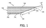
図1は、本発明の第1の実施例によるニードルの先端部分の断面図である。このニードル100は、縦軸又は中心軸150を持つシャフト110を含む。この中心軸と平行に2つの穿孔又は導管が形成され、これら穿孔又は導管内にファイバ130、140が夫々置かれる。これらファイバ、すなわち第1のファイバ130及び第2のファイバ140は夫々端面132、142を含む。 FIG. 1 is a sectional view of a tip portion of a needle according to a first embodiment of the present invention. The
さらに、シャフト110は、その遠位端において斜面120が形成されるように切断される。この斜面120は、斜面の上部122と名付けられる範囲及び斜面の下部と名付けられる範囲に分けられる傾斜面である。さらに、斜面120は、シャフト110の中心軸と角度bを囲む。この角度bは好ましくは、約20°の鋭角である。 Further, the
第1のファイバの端面132は斜面の上部に置かれ、第2のファイバ140の端面142は斜面の下部に置かれる。前記ファイバの端をシャフトにある穿孔又は導管内に位置決めた後、斜面は、これらファイバの端と一緒に研磨される。これによって、前記ファイバの2つの端面を含む滑らかな又はそれ以上の表面が達成され、このような研磨された端面は良好な光学特性を備える。 The
図1にさらに示されるように、距離Aが規定され、この距離は、第1のファイバ130の端面132の真ん中から、第2のファイバ140の端面142の真ん中までを測定している。 As further shown in FIG. 1, a distance A is defined that measures from the middle of the
図2は、本発明の第1の実施例によるニードルの正面図である。図2は、斜面120を、第1のファイバの端面132及び第2のファイバの端面142と一緒に示す。さらに、ニードル100のシャフトの通常は円形の断面は直径Dを規定する。前記距離A(図1参照)は、このニードルの外径Dよりも大きく、ここでA>1.1D或いはA>1.25D、好ましくはA>1.5Dである。 FIG. 2 is a front view of the needle according to the first embodiment of the present invention. FIG. 2 shows the
bを斜面の先端の角度とする場合、以下の数式
前記第1の実施例の事例において、前記ニードルは斜面の上部に第1のファイバを及び斜面の下部に第2のファイバを備え、第1のファイバは光を周囲組織内に放射する光源として役立ち、第2のファイバは反射した光を集める検出器ファイバとして役立つ。 In the case of the first embodiment, the needle comprises a first fiber at the top of the slope and a second fiber at the bottom of the slope, the first fiber serving as a light source that emits light into the surrounding tissue. The second fiber serves as a detector fiber that collects the reflected light.
図3は、本発明の第2の実施例によるニードルの正面図である。一般的に、第2の実施例は、第1の実施例に類似している。この第2の実施例もシャフト、このシャフトと鋭角を形成する斜面、この斜面の上部にある第1のファイバ及びこの斜面の下部にある第2のファイバを有する。 FIG. 3 is a front view of a needle according to a second embodiment of the present invention. In general, the second embodiment is similar to the first embodiment. This second embodiment also has a shaft, a slope forming an acute angle with the shaft, a first fiber at the top of the slope, and a second fiber at the bottom of the slope.
加えて、この第2の実施例によるニードルは、端面252を備える第3のファイバを有する。この第3のファイバは、シャフトの中心軸に平行に、すなわち第1及び第2のファイバの導管と平行に形成される導管内に又は穿孔を介して配される。さらに、第3のファイバの端面252は、斜面220の下部224において、前記第2のファイバの端面の近傍に置かれる。 In addition, the needle according to this second embodiment has a third fiber with an
前記第2の実施例の事例において、前記ニードルは斜面の上部に第1のファイバを並びに斜面の下部に第2及び第3のファイバを備え、第1のファイバは光を周囲組織内に放射する光源として役立ち、第2及び第3のファイバは反射した光を集める検出器ファイバとして役立つ。 In the case of the second embodiment, the needle comprises a first fiber at the top of the slope and second and third fibers at the bottom of the slope, the first fiber emitting light into the surrounding tissue. Serving as a light source, the second and third fibers serve as detector fibers that collect the reflected light.
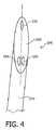
図4は、第2の実施例によるニードルの先端部分を等角図として示す。この図は、斜面の表面及びファイバの端面の実形状が略楕円であることを説明している。 FIG. 4 shows an isometric view of the tip of the needle according to the second embodiment. This figure explains that the actual shape of the surface of the slope and the end face of the fiber is substantially elliptical.
図5は、本発明によるシステムを説明している。このシステムは、本発明の第3の実施例によるニードル300を含む。この図において、ニードル300は、先端部310、内管352、外管350及びホルダー部360の組立体である。さらに、2本のファイバ330及び340がニードル内に示される。 FIG. 5 illustrates a system according to the invention. This system includes a
このニードルの重要な部分はニードルの先端であり、ここに2つ又は3つの穿孔が作られる。各穿孔においてファイバが接着剤により取り付けられている。前記先端は、溶接又は接着剤によって内管及び外管の両方に取り付けられ、内管及び外管の内径及び外径は、前記先端部の近位のシャフト部にある夫々の構造体に対応する。これら管の間に空間356が得られ、先端部にある貫通穿孔がその空間内に広がる。先端部の穿孔から出てくると、ファイバ330、340は、両方の管の間にある中空の空間356に位置決められる。 An important part of this needle is the tip of the needle, where two or three perforations are made. At each perforation, the fiber is attached with an adhesive. The tip is attached to both the inner and outer tubes by welding or adhesive, and the inner and outer diameters of the inner and outer tubes correspond to the respective structures in the shaft portion proximal to the tip. . A
一度組み立てられると、前記先端、ファイバ及び両方の管は、ニードルのホルダーに固定される。このホルダーの内部では、前記内管は例えばシリンジ(注射器)又は他の管類が取り付けられるコネクタに固定される。このようにして、液体は、ファイバと干渉することなく内管及び先端部の導管354を介し投与されることができる。ニードルのホルダー360はファイバのための別個の出口362も含む。先端、ファイバ、管及びホルダーを組み立てた後、ニードルの斜面(すなわちニードルの先端)320は、ファイバが適切な表面品質を得るように研磨される。 Once assembled, the tip, fiber and both tubes are secured to the needle holder. Inside the holder, the inner tube is fixed to a connector to which, for example, a syringe or other tubing is attached. In this way, liquid can be dispensed through the inner tube and the
ニードルの別の部分の適切な特性を持つために、先端部は金属、合金又はセラミック材料から作られ、シャフトの管は金属材料から作られ、ここで金属材料は、例えばチタンのようなMRI互換にすべきである。 In order to have the proper properties of another part of the needle, the tip is made of metal, alloy or ceramic material and the shaft tube is made of metal material, where the metal material is MRI compatible eg titanium Should be.
さらに、前記システムは、光源332、光検出器242、処理ユニット370及びモニター380を有する。処理ユニット370は、斜面320の上部にあるファイバ330の遠位の端面を通り周囲組織内に光が放射されるように、光がファイバ330内に放射するよう光源332を制御することが可能である。斜面の前にどんな組織があるかに応じて、放射される光のある程度は斜面の下部に向け反射され、他のファイバ340により受信される。ファイバ340を通って光は光検出器342に導かれ、この検出器は、光を電気信号に変換する。これら電気信号は、例えば処理ユニットまでの配線により送られる。この処理ユニットは、電気信号に対応するデータを処理するので、この処理されたデータはモニター380上に視覚化される。前記視覚化したデータに基づいて、組織が癌に侵されているかの診断をすることが可能である。 Further, the system includes a
以下において、本発明による例示的なニードルは、それの外径、挿入長及び好ましい使用に関して開示される。 In the following, an exemplary needle according to the present invention is disclosed with respect to its outer diameter, insertion length and preferred use.
生検ニードルは、1.27mmから2.108mmmの間の外径を持ち、その長さの100mmから150mmの間で組織内に挿入され、頸部、頭部、胸部、前立腺及び肝臓における軟組織コア生検に用いられる。 The biopsy needle has an outer diameter between 1.27 mm and 2.108 mm and is inserted into tissue between its length of 100 mm and 150 mm, and a soft tissue core in the neck, head, breast, prostate and liver Used for biopsy.
軟組織の微細針吸引用のニードルは、0.711mmから2.108mmの間の外径を持ち、その長さの100mmから150mmの間で軟組織内に挿入され、軟組織の吸引に用いられる。 The needle for sucking a soft tissue fine needle has an outer diameter of 0.711 mm to 2.108 mm, and is inserted into the soft tissue at a length of 100 mm to 150 mm, and is used for sucking the soft tissue.
脳生検ニードルは、2.108mmの外径を持ち、その長さの150mmから250mmの間で組織内に挿入され、脳生検を診断するのに用いられる。 The brain biopsy needle has an outer diameter of 2.108 mm and is inserted into the tissue between 150 mm and 250 mm in length and is used to diagnose a brain biopsy.
神経穿刺ニードルは、1.27mmから2.108mmの間の外径を持ち、その長さの150mmから200mmの間で組織内に挿入される。このようなニードルは脳内の腫瘍への非外傷性方法を可能にする。 The nerve puncture needle has an outer diameter between 1.27 mm and 2.108 mm and is inserted into the tissue between its length of 150 mm and 200 mm. Such needles allow for atraumatic methods for tumors in the brain.
硬膜外ニードルは、0.711mmから1.473mmの間の外径を持ち、150mmまでの長さを組織内に挿入され、硬膜外腔内にステロイドを注入するような、脊髄の部位の治療に用いられる。 The epidural needle has an outer diameter between 0.711 mm and 1.473 mm, is inserted into the tissue up to 150 mm in length, and is used for injecting steroids into the epidural space. Used for treatment.
最後に、ニードル電極は、2.108mm以下の外径を持ち、その長さの250mmまで組織内に挿入され、例えば腫瘍のラジオ波アブレーション(radiofrequency ablation)に用いられる。 Finally, the needle electrode has an outer diameter of 2.108 mm or less and is inserted into the tissue up to its length of 250 mm and is used, for example, for radiofrequency ablation of tumors.
本発明は、図面及び上記説明において詳細に説明及び開示されたのに対し、このような説明及び開示は、実例又は具体例であり、限定的であると考えるべきではない。つまり、本発明は開示される実施例に限定されない。 While the invention has been described and disclosed in detail in the drawings and foregoing description, such description and disclosure are exemplary or exemplary and are not to be considered as limiting. The invention is not limited to the disclosed embodiments.
これら開示される実施例に対する他の変形例は、図面、明細書及び特許請求の範囲の研究から、請求する本発明を実施する際に当業者により理解及び達成されることができる。請求項において、「有する」という言葉は、それ以外の要素又はステップを排除するものではなく、複数あることを述べないことが、それらが複数あることを排除するものではない。処理ユニットは、請求項に列挙した幾つかのアイテムの機能を実行してもよい。ある特定の方法が互いに異なる従属請求項に列挙されているという単なる事実は、これらの方法の組み合わせを有利に使用することができないことを示しているのではない。コンピュータプログラムは、他のハードウェアと一緒に若しくはその一部として供給される適切な媒体、例えば光学記憶媒体又はソリッドステート媒体に記憶/分配されるが、他の形式、例えばインターネット又は他の有線若しくは無線電話通信システムを介して分配されてもよい。請求項における如何なる参照符号も特許請求の範囲を制限すると解釈されるべきではない。 Other variations to these disclosed embodiments can be understood and accomplished by those skilled in the art in practicing the claimed invention, from a study of the drawings, specification, and claims. In the claims, the word “comprising” does not exclude other elements or steps, and the absence of a plurality does not exclude the presence of a plurality. The processing unit may perform the functions of several items recited in the claims. The mere fact that certain methods are recited in mutually different dependent claims does not indicate that a combination of these methods cannot be used to advantage. The computer program may be stored / distributed on a suitable medium supplied with or as part of other hardware, such as an optical storage medium or solid state medium, but in other formats such as the Internet or other wired or It may be distributed via a wireless telephone communication system. Any reference signs in the claims should not be construed as limiting the scope.
100、200、300 ニードル
110、210 シャフト
120、220、320 斜面
122 斜面の上部
124、224 斜面の下部
130、330 第1のファイバ
132、232 第1のファイバの端面
140、340 第2のファイバ
142、242 第2のファイバの端面
150 ニードルの縦軸
252 第3のファイバの端面
310 先端部
332 光源
343 光検出器
350 外管
352 内管
354 導管
356 内管と外管との間にある空間
360 ホルダー部分
362 開口
370 処理ユニット
380 モニター100, 200, 300
Claims (9)
Translated fromJapanese前記シャフトの遠位端にある先端であり、斜面により形成されるニードルの先端、
光の伝送が可能である第1のファイバであり、前記第1のファイバの端面は前記斜面の上部に置かれている第1のファイバ、及び
光の伝送が可能である第2のファイバであり、前記第2のファイバの端面は前記斜面の下部に置かれている第2のファイバ
を有するニードル。shaft,
A tip at the distal end of the shaft, the tip of the needle formed by a bevel,
A first fiber capable of transmitting light, an end face of the first fiber being a first fiber placed on top of the slope, and a second fiber capable of transmitting light A needle having a second fiber, wherein the end face of the second fiber is located below the slope.
−前記シャフトは外径を持ち、
−前記第1のファイバの端面及び前記第2のファイバの端面は、互いに距離を置いて配されている、
−前記距離は前記外径よりも大きい、
ニードル。The needle according to claim 1, wherein
The shaft has an outer diameter;
The end face of the first fiber and the end face of the second fiber are arranged at a distance from each other;
The distance is greater than the outer diameter;
needle.
請求項1に記載のニードル、
前記ニードルのファイバの1つと接続される光源、
前記ニードルのファイバの他の1つと接続される光検出器であり、前記光源から生じ、前記ファイバの1つの端面から放射される光が前記ファイバの他の1つに入射するとき前記光検出器により検出されることが可能である光検出器、
前記光検出器からのデータを処理する処理ユニット、並びに
前記処理したデータの視覚化のためのモニター
を有するシステム。In a system for optical histology,
The needle according to claim 1,
A light source connected to one of the fibers of the needle;
A photodetector connected to another one of the fibers of the needle, the light detector when light originating from the light source and emitted from one end face of the fiber is incident on the other one of the fibers A photodetector, which can be detected by
A system comprising a processing unit for processing data from the photodetector and a monitor for visualization of the processed data.
Applications Claiming Priority (3)
| Application Number | Priority Date | Filing Date | Title |
|---|---|---|---|
| EP08169409.3 | 2008-11-19 | ||
| EP08169409 | 2008-11-19 | ||
| PCT/IB2009/055128WO2010058344A1 (en) | 2008-11-19 | 2009-11-18 | Needle with optical fibers |
Publications (2)
| Publication Number | Publication Date |
|---|---|
| JP2012509161Atrue JP2012509161A (en) | 2012-04-19 |
| JP5739817B2 JP5739817B2 (en) | 2015-06-24 |
Family
ID=41480178
Family Applications (1)
| Application Number | Title | Priority Date | Filing Date |
|---|---|---|---|
| JP2011543876AActiveJP5739817B2 (en) | 2008-11-19 | 2009-11-18 | Needle with optical fiber |
Country Status (5)
| Country | Link |
|---|---|
| US (2) | US20110251494A1 (en) |
| EP (1) | EP2358263B1 (en) |
| JP (1) | JP5739817B2 (en) |
| CN (1) | CN102215741B (en) |
| WO (1) | WO2010058344A1 (en) |
Families Citing this family (18)
| Publication number | Priority date | Publication date | Assignee | Title |
|---|---|---|---|---|
| WO2009109879A2 (en)* | 2008-03-03 | 2009-09-11 | Koninklijke Philips Electronics N.V. | Biopsy guidance by electromagnetic tracking and photonic needle |
| JP2014518118A (en)* | 2011-06-28 | 2014-07-28 | コーニンクレッカ フィリップス エヌ ヴェ | Needle with optical fiber integrated into an elongated insert |
| US10064554B2 (en) | 2011-12-14 | 2018-09-04 | The Trustees Of The University Of Pennsylvania | Fiber optic flow and oxygenation monitoring using diffuse correlation and reflectance |
| JP5861000B2 (en) | 2012-06-26 | 2016-02-16 | コーニンクレッカ フィリップス エヌ ヴェKoninklijke Philips N.V. | Biopsy needle with large fiber spacing at the tip |
| GB201301280D0 (en)* | 2013-01-24 | 2013-03-06 | Univ St Andrews | Optical apparatus for use with a medical imager |
| CN105025808B (en)* | 2013-02-27 | 2018-11-20 | 皇家飞利浦有限公司 | Optical guidance vacuum assisted biopsy equipment |
| US9854961B2 (en) | 2013-04-03 | 2018-01-02 | Koninklijke Philips N.V. | Photonic needle with optimal bevel angle |
| US20160151055A1 (en)* | 2013-07-26 | 2016-06-02 | The Royal Institution For The Advacement Of Learning/Mcgill University | Biopsy device and method for obtaining a tomogram of a tissue volume using same |
| EP3102113B1 (en) | 2014-02-03 | 2019-08-07 | The University Of Western Australia | A medical device for insertion into a material to obtain a material sample |
| WO2015121115A1 (en)* | 2014-02-14 | 2015-08-20 | Koninklijke Philips N.V. | Photonic device with smooth tip and improved light output |
| US10405838B2 (en)* | 2014-08-28 | 2019-09-10 | Koninklijke Philips N.V. | Side-looking lung biopsy device |
| WO2016149701A1 (en) | 2015-03-19 | 2016-09-22 | The Regents Of The University Of Michigan | System for analyzing tissue |
| US10194981B2 (en)* | 2015-07-29 | 2019-02-05 | Medlumics S.L. | Radiofrequency ablation catheter with optical tissue evaluation |
| CN105943091A (en)* | 2016-06-01 | 2016-09-21 | 南京法迈特科技发展有限公司 | Endoscopic biopsy apparatus |
| CN206586974U (en)* | 2016-09-14 | 2017-10-27 | 深圳市前海康启源科技有限公司 | Biopsy needle scanning control system |
| CN206434352U (en)* | 2016-09-14 | 2017-08-25 | 深圳市前海康启源科技有限公司 | The biopsy needle control system of auxiliary positioning |
| CN106137264A (en)* | 2016-09-14 | 2016-11-23 | 深圳市前海康启源科技有限公司 | There is the biopsy needle control system of double light path image scanning function |
| CN109171905B (en)* | 2018-10-11 | 2020-06-30 | 青岛浦利医疗技术有限公司 | Puncture guiding device based on infrared imaging |
Citations (8)
| Publication number | Priority date | Publication date | Assignee | Title |
|---|---|---|---|---|
| US4566438A (en)* | 1984-10-05 | 1986-01-28 | Liese Grover J | Fiber-optic stylet for needle tip localization |
| US5460182A (en)* | 1992-09-14 | 1995-10-24 | Sextant Medical Corporation | Tissue penetrating apparatus and methods |
| JP2003528684A (en)* | 2000-03-31 | 2003-09-30 | リタ メディカル システムズ インコーポレイテッド | Tissue biopsy and treatment apparatus and method |
| JP2004510536A (en)* | 2000-10-12 | 2004-04-08 | インスティテュート フュア ミクロ テラピー ボーフム | Surgical instruments |
| JP2005501586A (en)* | 2001-09-04 | 2005-01-20 | バイオルミネイト, インコーポレイション | Multi-sensor probe for tissue identification |
| JP2006006919A (en)* | 2004-05-24 | 2006-01-12 | National Institute Of Advanced Industrial & Technology | In vivo tissue identification device |
| JP2006503680A (en)* | 2002-10-25 | 2006-02-02 | ゾーマテクス メディカル テクノロジーズ ゲーエムベーハー | Biopsy cannula biopsert support device |
| EP1884211A2 (en)* | 2006-08-02 | 2008-02-06 | Stephen D. Zuckerman | Optical device for needle placement into a joint |
Family Cites Families (5)
| Publication number | Priority date | Publication date | Assignee | Title |
|---|---|---|---|---|
| CN1784173A (en)* | 2003-03-17 | 2006-06-07 | 路易兹·B·达·席尔瓦 | Optical biopsy system with single-use needle probe |
| US20040249268A1 (en) | 2003-03-17 | 2004-12-09 | Da Silva Luiz B. | Optical biopsy system with single use needle probe |
| US20050203419A1 (en)* | 2004-02-24 | 2005-09-15 | Nirmala Ramanujam | Side-firing probe for performing optical spectroscopy during core needle biopsy |
| US7645286B2 (en)* | 2005-05-20 | 2010-01-12 | Neotract, Inc. | Devices, systems and methods for retracting, lifting, compressing, supporting or repositioning tissues or anatomical structures |
| EP2037795A2 (en)* | 2006-07-10 | 2009-03-25 | Boston Scientific Limited | Optical spectroscopic injection needle |
- 2009
- 2009-11-18WOPCT/IB2009/055128patent/WO2010058344A1/enactiveApplication Filing
- 2009-11-18JPJP2011543876Apatent/JP5739817B2/enactiveActive
- 2009-11-18EPEP09760611.5Apatent/EP2358263B1/enactiveActive
- 2009-11-18USUS13/129,171patent/US20110251494A1/ennot_activeAbandoned
- 2009-11-18CNCN200980146135.6Apatent/CN102215741B/enactiveActive
- 2016
- 2016-09-12USUS15/262,601patent/US11039750B2/enactiveActive
Patent Citations (8)
| Publication number | Priority date | Publication date | Assignee | Title |
|---|---|---|---|---|
| US4566438A (en)* | 1984-10-05 | 1986-01-28 | Liese Grover J | Fiber-optic stylet for needle tip localization |
| US5460182A (en)* | 1992-09-14 | 1995-10-24 | Sextant Medical Corporation | Tissue penetrating apparatus and methods |
| JP2003528684A (en)* | 2000-03-31 | 2003-09-30 | リタ メディカル システムズ インコーポレイテッド | Tissue biopsy and treatment apparatus and method |
| JP2004510536A (en)* | 2000-10-12 | 2004-04-08 | インスティテュート フュア ミクロ テラピー ボーフム | Surgical instruments |
| JP2005501586A (en)* | 2001-09-04 | 2005-01-20 | バイオルミネイト, インコーポレイション | Multi-sensor probe for tissue identification |
| JP2006503680A (en)* | 2002-10-25 | 2006-02-02 | ゾーマテクス メディカル テクノロジーズ ゲーエムベーハー | Biopsy cannula biopsert support device |
| JP2006006919A (en)* | 2004-05-24 | 2006-01-12 | National Institute Of Advanced Industrial & Technology | In vivo tissue identification device |
| EP1884211A2 (en)* | 2006-08-02 | 2008-02-06 | Stephen D. Zuckerman | Optical device for needle placement into a joint |
Also Published As
| Publication number | Publication date |
|---|---|
| EP2358263A1 (en) | 2011-08-24 |
| CN102215741B (en) | 2014-07-23 |
| EP2358263B1 (en) | 2013-07-10 |
| US20160374563A1 (en) | 2016-12-29 |
| US11039750B2 (en) | 2021-06-22 |
| WO2010058344A1 (en) | 2010-05-27 |
| US20110251494A1 (en) | 2011-10-13 |
| JP5739817B2 (en) | 2015-06-24 |
| CN102215741A (en) | 2011-10-12 |
Similar Documents
| Publication | Publication Date | Title |
|---|---|---|
| JP5739817B2 (en) | Needle with optical fiber | |
| US12324684B1 (en) | Detecting and avoiding blood vessels | |
| EP2358265B1 (en) | Needle with integrated fibers | |
| EP2419005B1 (en) | Needle with integrated fibers in the cutting facets of the bevel | |
| CN101959470B (en) | Biopsy guidance by electromagnetic tracking and photonic needle | |
| EP2961327B1 (en) | Optical guided vacuum assisted biopsy device | |
| US20160081712A1 (en) | Device, system, and method for insertion of a medical device into a subject | |
| JP2002263055A (en) | Tip hood for endoscope | |
| JP2012529332A (en) | Algorithm for photonic needle terminal | |
| EP3053507B1 (en) | Medical probe | |
| US10398508B2 (en) | Protective sheath and method of using same for laser surgery | |
| US10052086B2 (en) | Medical device for insertion into a material to obtain a material sample and a method thereof | |
| JP2012152399A (en) | Medical device for respiration area |
Legal Events
| Date | Code | Title | Description |
|---|---|---|---|
| A621 | Written request for application examination | Free format text:JAPANESE INTERMEDIATE CODE: A621 Effective date:20121116 | |
| A131 | Notification of reasons for refusal | Free format text:JAPANESE INTERMEDIATE CODE: A131 Effective date:20140109 | |
| A601 | Written request for extension of time | Free format text:JAPANESE INTERMEDIATE CODE: A601 Effective date:20140409 | |
| A602 | Written permission of extension of time | Free format text:JAPANESE INTERMEDIATE CODE: A602 Effective date:20140416 | |
| A521 | Request for written amendment filed | Free format text:JAPANESE INTERMEDIATE CODE: A523 Effective date:20140704 | |
| A02 | Decision of refusal | Free format text:JAPANESE INTERMEDIATE CODE: A02 Effective date:20141111 | |
| A521 | Request for written amendment filed | Free format text:JAPANESE INTERMEDIATE CODE: A523 Effective date:20150309 | |
| A911 | Transfer to examiner for re-examination before appeal (zenchi) | Free format text:JAPANESE INTERMEDIATE CODE: A911 Effective date:20150317 | |
| TRDD | Decision of grant or rejection written | ||
| A01 | Written decision to grant a patent or to grant a registration (utility model) | Free format text:JAPANESE INTERMEDIATE CODE: A01 Effective date:20150407 | |
| A61 | First payment of annual fees (during grant procedure) | Free format text:JAPANESE INTERMEDIATE CODE: A61 Effective date:20150424 | |
| R150 | Certificate of patent or registration of utility model | Ref document number:5739817 Country of ref document:JP Free format text:JAPANESE INTERMEDIATE CODE: R150 | |
| R250 | Receipt of annual fees | Free format text:JAPANESE INTERMEDIATE CODE: R250 | |
| R250 | Receipt of annual fees | Free format text:JAPANESE INTERMEDIATE CODE: R250 | |
| R250 | Receipt of annual fees | Free format text:JAPANESE INTERMEDIATE CODE: R250 | |
| R250 | Receipt of annual fees | Free format text:JAPANESE INTERMEDIATE CODE: R250 | |
| R250 | Receipt of annual fees | Free format text:JAPANESE INTERMEDIATE CODE: R250 | |
| R250 | Receipt of annual fees | Free format text:JAPANESE INTERMEDIATE CODE: R250 | |
| R250 | Receipt of annual fees | Free format text:JAPANESE INTERMEDIATE CODE: R250 |