JP2012509108A - Composite manifold for decompression - Google Patents
Composite manifold for decompressionDownload PDFInfo
- Publication number
- JP2012509108A JP2012509108AJP2011536594AJP2011536594AJP2012509108AJP 2012509108 AJP2012509108 AJP 2012509108AJP 2011536594 AJP2011536594 AJP 2011536594AJP 2011536594 AJP2011536594 AJP 2011536594AJP 2012509108 AJP2012509108 AJP 2012509108A
- Authority
- JP
- Japan
- Prior art keywords
- manifold
- peripheral
- manifold member
- composite
- bulk modulus
- Prior art date
- Legal status (The legal status is an assumption and is not a legal conclusion. Google has not performed a legal analysis and makes no representation as to the accuracy of the status listed.)
- Granted
Links
- 239000002131composite materialSubstances0.000titleclaimsabstractdescription87
- 230000006837decompressionEffects0.000titleclaimsdescription11
- 230000002093peripheral effectEffects0.000claimsabstractdescription127
- 238000000034methodMethods0.000claimsabstractdescription26
- 238000007789sealingMethods0.000claimsabstractdescription26
- 239000012530fluidSubstances0.000claimsabstractdescription17
- 239000000463materialSubstances0.000claimsdescription50
- 239000000126substanceSubstances0.000claimsdescription22
- 230000000975bioactive effectEffects0.000claimsdescription15
- 238000004519manufacturing processMethods0.000claimsdescription6
- UCTWMZQNUQWSLP-VIFPVBQESA-N(R)-adrenalineChemical compoundCNC[C@H](O)C1=CC=C(O)C(O)=C1UCTWMZQNUQWSLP-VIFPVBQESA-N0.000claimsdescription5
- 229930182837(R)-adrenalineNatural products0.000claimsdescription5
- 229960005139epinephrineDrugs0.000claimsdescription5
- 210000000981epitheliumAnatomy0.000claimsdescription5
- 239000003795chemical substances by applicationSubstances0.000claimsdescription2
- 238000002560therapeutic procedureMethods0.000claims2
- 229940088623biologically active substanceDrugs0.000claims1
- 230000001225therapeutic effectEffects0.000claims1
- 206010052428WoundDiseases0.000abstractdescription53
- 208000027418Wounds and injuryDiseases0.000abstractdescription53
- 230000006835compressionEffects0.000abstractdescription5
- 238000007906compressionMethods0.000abstractdescription5
- 210000001519tissueAnatomy0.000description32
- 239000004820Pressure-sensitive adhesiveSubstances0.000description6
- 239000006260foamSubstances0.000description6
- 210000004027cellAnatomy0.000description5
- 239000000853adhesiveSubstances0.000description4
- 230000001070adhesive effectEffects0.000description4
- 230000008901benefitEffects0.000description4
- 230000001413cellular effectEffects0.000description4
- 229920001971elastomerPolymers0.000description4
- 239000006261foam materialSubstances0.000description4
- 239000007788liquidSubstances0.000description4
- 238000001514detection methodMethods0.000description3
- 229920002635polyurethanePolymers0.000description3
- 239000004814polyurethaneSubstances0.000description3
- 102000009024Epidermal Growth FactorHuman genes0.000description2
- 101800003838Epidermal growth factorProteins0.000description2
- NTYJJOPFIAHURM-UHFFFAOYSA-NHistamineChemical compoundNCCC1=CN=CN1NTYJJOPFIAHURM-UHFFFAOYSA-N0.000description2
- 239000005062PolybutadieneSubstances0.000description2
- YKPUWZUDDOIDPM-SOFGYWHQSA-NcapsaicinChemical compoundCOC1=CC(CNC(=O)CCCC\C=C\C(C)C)=CC=C1OYKPUWZUDDOIDPM-SOFGYWHQSA-N0.000description2
- 239000000806elastomerSubstances0.000description2
- 229940116977epidermal growth factorDrugs0.000description2
- 210000002615epidermisAnatomy0.000description2
- HQQADJVZYDDRJT-UHFFFAOYSA-Nethene;prop-1-eneChemical groupC=C.CC=CHQQADJVZYDDRJT-UHFFFAOYSA-N0.000description2
- 239000000499gelSubstances0.000description2
- 230000035876healingEffects0.000description2
- 230000002209hydrophobic effectEffects0.000description2
- 230000002706hydrostatic effectEffects0.000description2
- 238000012544monitoring processMethods0.000description2
- 229940021182non-steroidal anti-inflammatory drugDrugs0.000description2
- 230000010412perfusionEffects0.000description2
- 229920002857polybutadienePolymers0.000description2
- 229920001296polysiloxanePolymers0.000description2
- 230000008569processEffects0.000description2
- 150000003180prostaglandinsChemical class0.000description2
- 239000005060rubberSubstances0.000description2
- 239000007921spraySubstances0.000description2
- VBEQCZHXXJYVRD-GACYYNSASA-NuroantheloneChemical compoundC([C@@H](C(=O)N[C@H](C(=O)N[C@@H](CS)C(=O)N[C@@H](CC(N)=O)C(=O)N[C@@H](CS)C(=O)N[C@H](C(=O)N[C@@H]([C@@H](C)CC)C(=O)NCC(=O)N[C@@H](CC=1C=CC(O)=CC=1)C(=O)N[C@@H](CO)C(=O)NCC(=O)N[C@@H](CC(O)=O)C(=O)N[C@@H](CCCNC(N)=N)C(=O)N[C@@H](CS)C(=O)N[C@@H](CCC(N)=O)C(=O)N[C@@H]([C@@H](C)O)C(=O)N[C@@H](CCCNC(N)=N)C(=O)N[C@@H](CC(O)=O)C(=O)N[C@@H](CC(C)C)C(=O)N[C@@H](CCCNC(N)=N)C(=O)N[C@@H](CC=1C2=CC=CC=C2NC=1)C(=O)N[C@@H](CC=1C2=CC=CC=C2NC=1)C(=O)N[C@@H](CCC(O)=O)C(=O)N[C@@H](CC(C)C)C(=O)N[C@@H](CCCNC(N)=N)C(O)=O)C(C)C)[C@@H](C)O)NC(=O)[C@H](CO)NC(=O)[C@H](CC(O)=O)NC(=O)[C@H](CC(C)C)NC(=O)[C@H](CO)NC(=O)[C@H](CCC(O)=O)NC(=O)[C@@H](NC(=O)[C@H](CC=1NC=NC=1)NC(=O)[C@H](CCSC)NC(=O)[C@H](CS)NC(=O)[C@@H](NC(=O)CNC(=O)CNC(=O)[C@H](CC(N)=O)NC(=O)[C@H](CC(C)C)NC(=O)[C@H](CS)NC(=O)[C@H](CC=1C=CC(O)=CC=1)NC(=O)CNC(=O)[C@H](CC(O)=O)NC(=O)[C@H](CC=1C=CC(O)=CC=1)NC(=O)[C@H](CO)NC(=O)[C@H](CO)NC(=O)[C@H]1N(CCC1)C(=O)[C@H](CS)NC(=O)CNC(=O)[C@H]1N(CCC1)C(=O)[C@H](CC=1C=CC(O)=CC=1)NC(=O)[C@H](CO)NC(=O)[C@@H](N)CC(N)=O)C(C)C)[C@@H](C)CC)C1=CC=C(O)C=C1VBEQCZHXXJYVRD-GACYYNSASA-N0.000description2
- 238000009489vacuum treatmentMethods0.000description2
- 229940124549vasodilatorDrugs0.000description2
- 239000003071vasodilator agentSubstances0.000description2
- 102000019034ChemokinesHuman genes0.000description1
- 108010012236ChemokinesProteins0.000description1
- 229920001634CopolyesterPolymers0.000description1
- 108010049003FibrinogenProteins0.000description1
- 102000008946FibrinogenHuman genes0.000description1
- 102000003972Fibroblast growth factor 7Human genes0.000description1
- 108090000385Fibroblast growth factor 7Proteins0.000description1
- 102000016359FibronectinsHuman genes0.000description1
- 108010067306FibronectinsProteins0.000description1
- 208000032843HemorrhageDiseases0.000description1
- 244000043261Hevea brasiliensisSpecies0.000description1
- 108090000723Insulin-Like Growth Factor IProteins0.000description1
- NNJVILVZKWQKPM-UHFFFAOYSA-NLidocaineChemical compoundCCN(CC)CC(=O)NC1=C(C)C=CC=C1CNNJVILVZKWQKPM-UHFFFAOYSA-N0.000description1
- 229920000459Nitrile rubberPolymers0.000description1
- 102000010780Platelet-Derived Growth FactorHuman genes0.000description1
- 108010038512Platelet-Derived Growth FactorProteins0.000description1
- -1PolyethylenePolymers0.000description1
- 239000004698PolyethyleneSubstances0.000description1
- 239000004721Polyphenylene oxideSubstances0.000description1
- 102000013275SomatomedinsHuman genes0.000description1
- 208000027276Von Willebrand diseaseDiseases0.000description1
- NIXOWILDQLNWCW-UHFFFAOYSA-Nacrylic acid groupChemical groupC(C=C)(=O)ONIXOWILDQLNWCW-UHFFFAOYSA-N0.000description1
- 238000007792additionMethods0.000description1
- 210000001789adipocyteAnatomy0.000description1
- 229940035676analgesicsDrugs0.000description1
- 239000000730antalgic agentSubstances0.000description1
- 230000000844anti-bacterial effectEffects0.000description1
- 239000004599antimicrobialSubstances0.000description1
- 238000013459approachMethods0.000description1
- 239000011324beadSubstances0.000description1
- 239000012867bioactive agentSubstances0.000description1
- 230000005540biological transmissionEffects0.000description1
- 230000000740bleeding effectEffects0.000description1
- 239000008280bloodSubstances0.000description1
- 210000004369bloodAnatomy0.000description1
- 210000002449bone cellAnatomy0.000description1
- MTAZNLWOLGHBHU-UHFFFAOYSA-Nbutadiene-styrene rubberChemical compoundC=CC=C.C=CC1=CC=CC=C1MTAZNLWOLGHBHU-UHFFFAOYSA-N0.000description1
- 229920005549butyl rubberPolymers0.000description1
- 229960002504capsaicinDrugs0.000description1
- 235000017663capsaicinNutrition0.000description1
- 210000000845cartilageAnatomy0.000description1
- 230000004663cell proliferationEffects0.000description1
- XTHPWXDJESJLNJ-UHFFFAOYSA-MchlorosulfateChemical compound[O-]S(Cl)(=O)=OXTHPWXDJESJLNJ-UHFFFAOYSA-M0.000description1
- 210000002808connective tissueAnatomy0.000description1
- 238000001804debridementMethods0.000description1
- 230000003412degenerative effectEffects0.000description1
- 210000004207dermisAnatomy0.000description1
- 150000001993dienesChemical class0.000description1
- 230000005489elastic deformationEffects0.000description1
- 239000013536elastomeric materialSubstances0.000description1
- 238000005516engineering processMethods0.000description1
- 239000005038ethylene vinyl acetateSubstances0.000description1
- 230000007717exclusionEffects0.000description1
- 238000004299exfoliationMethods0.000description1
- 210000000416exudates and transudateAnatomy0.000description1
- 229940012952fibrinogenDrugs0.000description1
- 239000003292glueSubstances0.000description1
- 230000037313granulation tissue formationEffects0.000description1
- 239000003102growth factorSubstances0.000description1
- 229960001340histamineDrugs0.000description1
- 239000000416hydrocolloidSubstances0.000description1
- 239000000017hydrogelSubstances0.000description1
- 238000011065in-situ storageMethods0.000description1
- 208000015181infectious diseaseDiseases0.000description1
- 208000014674injuryDiseases0.000description1
- 229960004194lidocaineDrugs0.000description1
- 210000003041ligamentAnatomy0.000description1
- 239000012567medical materialSubstances0.000description1
- 239000012528membraneSubstances0.000description1
- 238000012986modificationMethods0.000description1
- 230000004048modificationEffects0.000description1
- 239000000178monomerSubstances0.000description1
- 210000000663muscle cellAnatomy0.000description1
- 229920003052natural elastomerPolymers0.000description1
- 229920001194natural rubberPolymers0.000description1
- 230000001338necrotic effectEffects0.000description1
- 210000000056organAnatomy0.000description1
- 206010033675panniculitisDiseases0.000description1
- 230000001575pathological effectEffects0.000description1
- 229920001084poly(chloroprene)Polymers0.000description1
- 229920001200poly(ethylene-vinyl acetate)Polymers0.000description1
- 229920000570polyetherPolymers0.000description1
- 229920000573polyethylenePolymers0.000description1
- 239000004848polyfunctional curativeSubstances0.000description1
- 229920001195polyisoprenePolymers0.000description1
- 239000002861polymer materialSubstances0.000description1
- 229920001021polysulfidePolymers0.000description1
- 239000005077polysulfideSubstances0.000description1
- 150000008117polysulfidesPolymers0.000description1
- 239000011148porous materialSubstances0.000description1
- 238000011084recoveryMethods0.000description1
- 230000009467reductionEffects0.000description1
- 229910052709silverInorganic materials0.000description1
- 239000004332silverSubstances0.000description1
- 210000003491skinAnatomy0.000description1
- 210000004927skin cellAnatomy0.000description1
- 210000004304subcutaneous tissueAnatomy0.000description1
- 238000006467substitution reactionMethods0.000description1
- 210000002435tendonAnatomy0.000description1
- DSNBHJFQCNUKMA-SCKDECHMSA-Nthromboxane A2Chemical compoundOC(=O)CCC\C=C/C[C@@H]1[C@@H](/C=C/[C@@H](O)CCCCC)O[C@@H]2O[C@H]1C2DSNBHJFQCNUKMA-SCKDECHMSA-N0.000description1
- 230000008733traumaEffects0.000description1
- 210000005167vascular cellAnatomy0.000description1
- 208000012137von Willebrand disease (hereditary or acquired)Diseases0.000description1
- 238000003466weldingMethods0.000description1
- 230000029663wound healingEffects0.000description1
Images


Classifications
- A—HUMAN NECESSITIES
- A61—MEDICAL OR VETERINARY SCIENCE; HYGIENE
- A61F—FILTERS IMPLANTABLE INTO BLOOD VESSELS; PROSTHESES; DEVICES PROVIDING PATENCY TO, OR PREVENTING COLLAPSING OF, TUBULAR STRUCTURES OF THE BODY, e.g. STENTS; ORTHOPAEDIC, NURSING OR CONTRACEPTIVE DEVICES; FOMENTATION; TREATMENT OR PROTECTION OF EYES OR EARS; BANDAGES, DRESSINGS OR ABSORBENT PADS; FIRST-AID KITS
- A61F13/00—Bandages or dressings; Absorbent pads
- A61F13/05—Bandages or dressings; Absorbent pads specially adapted for use with sub-pressure or over-pressure therapy, wound drainage or wound irrigation, e.g. for use with negative-pressure wound therapy [NPWT]
- A—HUMAN NECESSITIES
- A61—MEDICAL OR VETERINARY SCIENCE; HYGIENE
- A61M—DEVICES FOR INTRODUCING MEDIA INTO, OR ONTO, THE BODY; DEVICES FOR TRANSDUCING BODY MEDIA OR FOR TAKING MEDIA FROM THE BODY; DEVICES FOR PRODUCING OR ENDING SLEEP OR STUPOR
- A61M1/00—Suction or pumping devices for medical purposes; Devices for carrying-off, for treatment of, or for carrying-over, body-liquids; Drainage systems
- A61M1/90—Negative pressure wound therapy devices, i.e. devices for applying suction to a wound to promote healing, e.g. including a vacuum dressing
- A61M1/91—Suction aspects of the dressing
- A61M1/915—Constructional details of the pressure distribution manifold
- A—HUMAN NECESSITIES
- A61—MEDICAL OR VETERINARY SCIENCE; HYGIENE
- A61F—FILTERS IMPLANTABLE INTO BLOOD VESSELS; PROSTHESES; DEVICES PROVIDING PATENCY TO, OR PREVENTING COLLAPSING OF, TUBULAR STRUCTURES OF THE BODY, e.g. STENTS; ORTHOPAEDIC, NURSING OR CONTRACEPTIVE DEVICES; FOMENTATION; TREATMENT OR PROTECTION OF EYES OR EARS; BANDAGES, DRESSINGS OR ABSORBENT PADS; FIRST-AID KITS
- A61F13/00—Bandages or dressings; Absorbent pads
- A61F13/00987—Apparatus or processes for manufacturing non-adhesive dressings or bandages
- A61F13/00991—Apparatus or processes for manufacturing non-adhesive dressings or bandages for treating webs, e.g. for moisturising, coating, impregnating or applying powder
- A—HUMAN NECESSITIES
- A61—MEDICAL OR VETERINARY SCIENCE; HYGIENE
- A61L—METHODS OR APPARATUS FOR STERILISING MATERIALS OR OBJECTS IN GENERAL; DISINFECTION, STERILISATION OR DEODORISATION OF AIR; CHEMICAL ASPECTS OF BANDAGES, DRESSINGS, ABSORBENT PADS OR SURGICAL ARTICLES; MATERIALS FOR BANDAGES, DRESSINGS, ABSORBENT PADS OR SURGICAL ARTICLES
- A61L15/00—Chemical aspects of, or use of materials for, bandages, dressings or absorbent pads
- A61L15/16—Bandages, dressings or absorbent pads for physiological fluids such as urine or blood, e.g. sanitary towels, tampons
- A61L15/42—Use of materials characterised by their function or physical properties
- A61L15/44—Medicaments
- A—HUMAN NECESSITIES
- A61—MEDICAL OR VETERINARY SCIENCE; HYGIENE
- A61M—DEVICES FOR INTRODUCING MEDIA INTO, OR ONTO, THE BODY; DEVICES FOR TRANSDUCING BODY MEDIA OR FOR TAKING MEDIA FROM THE BODY; DEVICES FOR PRODUCING OR ENDING SLEEP OR STUPOR
- A61M1/00—Suction or pumping devices for medical purposes; Devices for carrying-off, for treatment of, or for carrying-over, body-liquids; Drainage systems
- A—HUMAN NECESSITIES
- A61—MEDICAL OR VETERINARY SCIENCE; HYGIENE
- A61P—SPECIFIC THERAPEUTIC ACTIVITY OF CHEMICAL COMPOUNDS OR MEDICINAL PREPARATIONS
- A61P17/00—Drugs for dermatological disorders
- A61P17/02—Drugs for dermatological disorders for treating wounds, ulcers, burns, scars, keloids, or the like
- A—HUMAN NECESSITIES
- A61—MEDICAL OR VETERINARY SCIENCE; HYGIENE
- A61F—FILTERS IMPLANTABLE INTO BLOOD VESSELS; PROSTHESES; DEVICES PROVIDING PATENCY TO, OR PREVENTING COLLAPSING OF, TUBULAR STRUCTURES OF THE BODY, e.g. STENTS; ORTHOPAEDIC, NURSING OR CONTRACEPTIVE DEVICES; FOMENTATION; TREATMENT OR PROTECTION OF EYES OR EARS; BANDAGES, DRESSINGS OR ABSORBENT PADS; FIRST-AID KITS
- A61F13/00—Bandages or dressings; Absorbent pads
- A61F2013/00089—Wound bandages
- A61F2013/0028—Wound bandages applying of mechanical pressure; passive massage
- A—HUMAN NECESSITIES
- A61—MEDICAL OR VETERINARY SCIENCE; HYGIENE
- A61F—FILTERS IMPLANTABLE INTO BLOOD VESSELS; PROSTHESES; DEVICES PROVIDING PATENCY TO, OR PREVENTING COLLAPSING OF, TUBULAR STRUCTURES OF THE BODY, e.g. STENTS; ORTHOPAEDIC, NURSING OR CONTRACEPTIVE DEVICES; FOMENTATION; TREATMENT OR PROTECTION OF EYES OR EARS; BANDAGES, DRESSINGS OR ABSORBENT PADS; FIRST-AID KITS
- A61F13/00—Bandages or dressings; Absorbent pads
- A61F2013/00089—Wound bandages
- A61F2013/00314—Wound bandages with surface treatments
- A—HUMAN NECESSITIES
- A61—MEDICAL OR VETERINARY SCIENCE; HYGIENE
- A61M—DEVICES FOR INTRODUCING MEDIA INTO, OR ONTO, THE BODY; DEVICES FOR TRANSDUCING BODY MEDIA OR FOR TAKING MEDIA FROM THE BODY; DEVICES FOR PRODUCING OR ENDING SLEEP OR STUPOR
- A61M1/00—Suction or pumping devices for medical purposes; Devices for carrying-off, for treatment of, or for carrying-over, body-liquids; Drainage systems
- A61M1/71—Suction drainage systems
- A—HUMAN NECESSITIES
- A61—MEDICAL OR VETERINARY SCIENCE; HYGIENE
- A61M—DEVICES FOR INTRODUCING MEDIA INTO, OR ONTO, THE BODY; DEVICES FOR TRANSDUCING BODY MEDIA OR FOR TAKING MEDIA FROM THE BODY; DEVICES FOR PRODUCING OR ENDING SLEEP OR STUPOR
- A61M2205/00—General characteristics of the apparatus
- A61M2205/02—General characteristics of the apparatus characterised by a particular materials
- A61M2205/0216—Materials providing elastic properties, e.g. for facilitating deformation and avoid breaking
- A—HUMAN NECESSITIES
- A61—MEDICAL OR VETERINARY SCIENCE; HYGIENE
- A61M—DEVICES FOR INTRODUCING MEDIA INTO, OR ONTO, THE BODY; DEVICES FOR TRANSDUCING BODY MEDIA OR FOR TAKING MEDIA FROM THE BODY; DEVICES FOR PRODUCING OR ENDING SLEEP OR STUPOR
- A61M2207/00—Methods of manufacture, assembly or production
- A—HUMAN NECESSITIES
- A61—MEDICAL OR VETERINARY SCIENCE; HYGIENE
- A61M—DEVICES FOR INTRODUCING MEDIA INTO, OR ONTO, THE BODY; DEVICES FOR TRANSDUCING BODY MEDIA OR FOR TAKING MEDIA FROM THE BODY; DEVICES FOR PRODUCING OR ENDING SLEEP OR STUPOR
- A61M27/00—Drainage appliance for wounds or the like, i.e. wound drains, implanted drains
- Y—GENERAL TAGGING OF NEW TECHNOLOGICAL DEVELOPMENTS; GENERAL TAGGING OF CROSS-SECTIONAL TECHNOLOGIES SPANNING OVER SEVERAL SECTIONS OF THE IPC; TECHNICAL SUBJECTS COVERED BY FORMER USPC CROSS-REFERENCE ART COLLECTIONS [XRACs] AND DIGESTS
- Y10—TECHNICAL SUBJECTS COVERED BY FORMER USPC
- Y10T—TECHNICAL SUBJECTS COVERED BY FORMER US CLASSIFICATION
- Y10T29/00—Metal working
- Y10T29/49—Method of mechanical manufacture
- Y10T29/49826—Assembling or joining
- Y10T29/49885—Assembling or joining with coating before or during assembling
Landscapes
- Health & Medical Sciences (AREA)
- Heart & Thoracic Surgery (AREA)
- Engineering & Computer Science (AREA)
- Life Sciences & Earth Sciences (AREA)
- Veterinary Medicine (AREA)
- Public Health (AREA)
- General Health & Medical Sciences (AREA)
- Animal Behavior & Ethology (AREA)
- Biomedical Technology (AREA)
- Vascular Medicine (AREA)
- Hematology (AREA)
- Anesthesiology (AREA)
- Chemical & Material Sciences (AREA)
- Medicinal Chemistry (AREA)
- Bioinformatics & Cheminformatics (AREA)
- Pharmacology & Pharmacy (AREA)
- General Chemical & Material Sciences (AREA)
- Chemical Kinetics & Catalysis (AREA)
- Organic Chemistry (AREA)
- Dermatology (AREA)
- Nuclear Medicine, Radiotherapy & Molecular Imaging (AREA)
- Manufacturing & Machinery (AREA)
- Otolaryngology (AREA)
- Materials Engineering (AREA)
- Epidemiology (AREA)
- Media Introduction/Drainage Providing Device (AREA)
- Acyclic And Carbocyclic Compounds In Medicinal Compositions (AREA)
Abstract
Translated fromJapaneseDescription
Translated fromJapanese関連出願
本発明は、2008年11月18日提出の米国暫定特許出願第61/115,763号“A Reduced−Pressure,Composite Manifold”について、35USC119条(e)に基づく利益を主張するものであり、当該暫定特許出願はすべての目的において参照により本書に組み込まれるものとする。RELATED APPLICATIONS This invention claims the benefit under 35 USC 119 (e) for US Provisional Patent Application No. 61 / 115,763 “A Reduced-Pressure, Composite Manifold” filed November 18, 2008. The provisional patent application is hereby incorporated by reference for all purposes.
本発明は、一般的に医療システムに関するものであり、より具体的には、減圧用複合型マニホルドとその方法ならびにシステムに関する。 The present invention relates generally to medical systems, and more specifically to a reduced pressure manifold and method and system.
臨床研究とその実務は、組織部位近傍に減圧を提供することが当該組織部位における新しい細胞組織の成長をもたらし、それを加速させることを示している。この現象の適用は多数あるが、減圧の適用が創傷治療にとりわけ成功している。この治療(医療業界ではしばしば「負圧創傷治療」あるいは「減圧治療」もしくは「真空治療」と呼ばれる)は、より速い治癒と肉芽組織の形成増加を含めて数々の利点を提供している。一般的に減圧は、ポーラス状のパッドあるいはその他のマニホルドデバイスを介して細胞組織に適用される。ポーラス状のパッドは、細胞組織に減圧を分配すると共に細胞組織から出る流体を導引できるセルや微細孔を具えている。 Clinical studies and practices have shown that providing reduced pressure in the vicinity of a tissue site results in and accelerates the growth of new cellular tissue at that tissue site. Although there are many applications of this phenomenon, the application of reduced pressure is particularly successful for wound healing. This treatment (often referred to in the medical industry as “negative pressure wound treatment” or “vacuum treatment” or “vacuum treatment”) offers numerous advantages, including faster healing and increased granulation tissue formation. In general, reduced pressure is applied to cellular tissue via a porous pad or other manifold device. The porous pad is provided with cells and micropores that can distribute the reduced pressure to the cellular tissue and also draw fluid exiting the cellular tissue.
減圧治療の過程では、壊死した細胞組織と一緒に組織片が剥離したり、あるいは創縁部で他の組織片が剥離することがある。このような組織片の剥離は、医療補助者が外傷用医療材料を交換する度毎の創傷清拭時にも発生し得るものである。 In the process of decompression treatment, a tissue piece may be detached together with the necrotic cell tissue, or another tissue piece may be detached at the wound edge. Such exfoliation of the tissue piece can also occur at the time of debridement every time the medical assistant changes the medical material for trauma.
ここに記載された実施例に開示されたドレッシング、システム及び方法は既存の減圧システム及び方法に伴う問題点に取り組むものである。 The dressings, systems and methods disclosed in the embodiments described herein address the problems associated with existing decompression systems and methods.
非限定的な実施例によれば、患者の創傷を治療する減圧治療システムは、複合型マニホルドと、患者の表皮に連結され創傷の上に流体シールを形成するよう作動するシーリング部材と、複合型マニホルドに減圧を提供する減圧サブシステムとを具えている。この複合型マニホルドは、創傷のエッジに隣接して配置すると共に内側部分を有する周縁マニホルド部材と、この周縁マニホルド部材の内側部分に隣接して配置された内側マニホルド部材とを具えている。周縁マニホルド部材は、治療減圧時にシーリング部材によって伝達される圧縮力の下で潰れないような適宜の強度を持って形成されている。 According to a non-limiting example, a reduced pressure treatment system for treating a patient's wound includes a composite manifold, a sealing member coupled to the patient's epidermis and operative to form a fluid seal over the wound, And a vacuum subsystem that provides vacuum to the manifold. The composite manifold includes a peripheral manifold member disposed adjacent to the wound edge and having an inner portion, and an inner manifold member disposed adjacent to the inner portion of the peripheral manifold member. The peripheral manifold member is formed with an appropriate strength so as not to be crushed under the compressive force transmitted by the sealing member during treatment decompression.
別の非限定的な実施例によれば、減圧治療システムに用いる複合型マニホルドは、創傷エッジに隣接して配置すると共に内側部分を有する周縁マニホルド部材と、この周縁マニホルド部材の内側部分に隣接して配置された内側マニホルド部材とを具える。周縁マニホルド部材は、治療減圧下で潰れないような適宜の強度を持って形成されている。 According to another non-limiting example, a composite manifold for use in a reduced pressure treatment system includes a peripheral manifold member positioned adjacent to the wound edge and having an inner portion, and an adjacent inner portion of the peripheral manifold member. And an inner manifold member arranged. The peripheral manifold member is formed with an appropriate strength so as not to be crushed under reduced pressure of treatment.
別の非限定的な実施例によれば、減圧治療システムに使用する複合型マニホルドを製造する方法は、創傷エッジに隣接して配置する周縁マニホルド部材を形成するステップと、内側マニホルド部材を形成するステップと、周縁マニホルド部材の内側部分に隣接して内側マニホルド部材を配置するステップとを具える。周縁マニホルド部材は、治療減圧下で潰れないような適宜の強度を持たって形成されている。 According to another non-limiting example, a method of manufacturing a composite manifold for use in a reduced pressure treatment system includes forming a peripheral manifold member for placement adjacent to a wound edge and forming an inner manifold member. And placing an inner manifold member adjacent the inner portion of the peripheral manifold member. The peripheral manifold member is formed with an appropriate strength that does not collapse under reduced pressure of treatment.
別の非限定的な実施例によれば、患者の創傷部位を減圧で治療する方法は、複合型マニホルドを創傷部位近傍に配置するステップと、複合型マニホルドの上に流体シールを形成するステップと、減圧源を複合型マニホルドに流体連結するステップと、を具える。複合型マニホルドは、創傷エッジに隣接して配置され、内側部分を有する周縁マニホルド部材と、周縁マニホルド部材の内側部分に隣接して配置された内側マニホルド部材とを具える。周縁マニホルド部材は、治療減圧下で潰れないような適宜の強度を持って形成されている。 According to another non-limiting example, a method of treating a patient's wound site with reduced pressure includes placing the composite manifold proximate the wound site and forming a fluid seal over the composite manifold. Fluidly connecting a reduced pressure source to the composite manifold. The composite manifold includes a peripheral manifold member disposed adjacent to the wound edge and having an inner portion and an inner manifold member disposed adjacent to the inner portion of the peripheral manifold member. The peripheral manifold member is formed with an appropriate strength so as not to be crushed under reduced pressure of treatment.
別の非限定的な実施例によれば、減圧治療システムに使用する複合型マニホルドは、創傷エッジ近傍に配置する周縁マニホルド部材と、周縁マニホルド部材に隣接して配置した内側マニホルド部材とを具え、周縁マニホルド部材が内側マニホルド部材よりも圧縮率がより硬い。 According to another non-limiting example, a composite manifold for use in a reduced pressure treatment system comprises a peripheral manifold member disposed near the wound edge and an inner manifold member disposed adjacent to the peripheral manifold member; The peripheral manifold member is harder in compression than the inner manifold member.
実施例のその他の目的、特徴、および利点は、図面を参照しながら以下に述べる詳細な説明の中で明らかになる。 Other objects, features, and advantages of the embodiments will become apparent in the detailed description given below with reference to the drawings.
添付図面に関連させて以下の詳細な説明を参照することによって、本発明をより完全に理解することができる。
以下に述べる実施例の詳細な説明においては、その一部を構成している添付図面を参照する。これらの実施例は、当業者が本発明を実施できるよう充分詳細に記述されており、その他の実施例を活用することができ、本発明の精神と範囲から逸脱することなく論理構造的、機械的、電気的、及び化学的変更を行うことができると理解するべきである。ここに記載された実施例を当業者が実施するのに不必な詳細を避けるため、この記載では当業者に公知である情報は省略している。従って、以下の詳細な説明は限定的な意味で解するべきではなく、この実施例の範囲は特許請求の範囲によってのみ規定される。 In the following detailed description of the embodiments, reference is made to the accompanying drawings that form a part hereof. These embodiments are described in sufficient detail to enable those skilled in the art to practice the invention, other embodiments can be utilized, and logical structures, machines, etc., without departing from the spirit and scope of the invention. It should be understood that mechanical, electrical, and chemical changes can be made. In this description, information known to those skilled in the art is omitted in order to avoid details unnecessary for those skilled in the art to implement the embodiments described herein. The following detailed description is, therefore, not to be taken in a limiting sense, and the scope of this embodiment is defined only by the appended claims.
図1Aおよび図1Bを参照すると、創傷床の中央にある組織部位104の創傷102を治療する減圧治療システム100の非限定的な実施例が開示されている。創傷102は、表皮103および真皮105そして皮下組織107を貫通している、あるいはこれらを含んでいる。減圧治療システム100は、その他の組織部位にも用いることができる。組織部位104は、骨細胞、脂肪細胞、筋細胞、皮膚細胞、血管細胞、結合組織、軟骨、腱、靭帯その他の組織細胞を含む、ヒトや動物の体組織あるいはその他の器官である。特に表示無い限り、ここで言う「又は」は、相互に排除することを意味するものではない。 With reference to FIGS. 1A and 1B, a non-limiting example of a reduced
減圧治療システム100は複合型マニホルド108を具える。更に、減圧治療システム100は、シーリング部材111と減圧サブシステム113を具える。複合型マニホルド108は、周縁マニホルド部材110と内側マニホルド部材112を具える。 The reduced
一の実施例では、周縁マニホルド部材110と内側マニホルド部材112は、ポーラス状の通気性のある発泡材あるいは泡状の物質でできており、より具体的には、減圧下において創傷の流体をよく透過させる網目状のオープンセル型ポリウレタン又はポリエーテルフォームでできている。使用されているこのような発泡材料の1つは、テキサス州サン・アントニオ市のキネティック・コンセプト社(KCI)から入手可能なVAC(登録商標)GranuFoam(登録商標)ドレッシングである。マニホルド材が減圧を供給するよう動作するものであれば、どのような材料又は材料の組み合せでもマニホルド材として使用することができる。ここで用いられている用語「マニホルド」は、通常、組織部位への減圧の適用、流体の送達、又は組織部位からの流体の除去を支援するべく設けられた物質又は構造を意味する。マニホルドは通常、複数の流路あるいは通路を有する。複数の流路は相互接続されており、マニホルド周辺の組織部位領域へ提供された、及びこの組織部位領域から除去された流体の流通を改善する。マニホルドの例は、流路を形成するように配置された構造エレメントを有するデバイス、開セル型フォームなどの多孔質フォーム、ポーラス状組織の集合体、及び、液体、ゲル、流路を持つあるいは流路を形成するように硬化するフォーム、などが、限定することなく含まれる。マニホルド材はまた材料の組み合わせ又は層であっても良く、例えば親水性発泡材でできた第1のマニホルド層を疎水性発泡材でできた第2のマニホルド層に隣接して配置して、複合体マニホルド108を形成してもよい。 In one embodiment, the
GranuFoam(登録商標)材の網目状の微細孔は約400〜600ミクロンの範囲にあり、マニホルド機能を行ううえで有用であるが、ここでもその他の材料を用いるようにしても良い。いくつかの場合、GranuFoam(登録商標)材よりも高密度あるいは低密度(微細孔のサイズがより小さい)材料が望ましい。使用できる様々な材料の中でも、GranuFoam(登録商標)材あるいはFoamex(登録商標)テクニカルフォーム(www.foamex.com)を使用することができる。いくつかの場合、マイクロボンディング工程においてこのフォームにイオン化銀を加えるか、又は抗菌剤などのその他の物質を材料に加えることが望ましい。複合型マニホルド108は、生体吸収性材料又は抗菌性材料であってもよい。 The network-like micropores of the GranFooam® material are in the range of about 400 to 600 microns and are useful for performing the manifold function, but other materials may be used here as well. In some cases, a higher or lower density (smaller pore size) material is desirable than a GranuFoam® material. Among the various materials that can be used, the GranuFoam (R) material or the Foamex (R) technical form (www.foamex.com) can be used. In some cases, it is desirable to add ionized silver to the foam in the microbonding process, or to add other substances such as antimicrobial agents to the material. The
複合型マニホルド108は、創傷エッジ109あるいは組織エッジを含む状態への対処を支援する。創傷エッジ109の組織部位上の圧力パターンは、組織の病的状態を増加させることがある。しばしば、マニホルド内で減圧が上がるので、創傷エッジ109に力が加わる。創傷エッジ109における圧力は、創傷縁部での灌流を減少させることがある。
周縁マニホルド部材110は、創傷エッジ109を支持している。一の態様では、周縁マニホルド部材110は、創傷エッジ109を挟んだり押し出したりすることを減らす複合型マニホルド108になる。周縁マニホルド部材110は、内側マニホルド部材112よりも硬い、すなわち加圧下での圧縮が少ないマニホルド材で形成することができる。周縁マニホルド部材110は、周縁マニホルド部材110が担わないのであれば、創縁マージン又は創傷エッジ109によって支えられるであろう力を担持している。従って、周縁マニホルド110を使用して、創傷エッジ109において加えられるであろう圧力の量を減らすことができる。周縁マニホルド部材110は、減圧下にあるときにシーリング部材111が創傷エッジ109上で直接的に引っ張られないように保持する。言い換えれば、周縁マニホルド部材110は、シーリング部材111によって生じる内向きの力の、複合マニホルド108への伝達を支援すると共に、創傷エッジ109にかかる力を低減する。この伝達は、創傷エッジ109における灌流を増加させると考えられている。
周縁マニホルド部材110は、治療レンジにおける実質的減圧下で、潰れないように設計されており、通常は、内側マニホルド部材112より硬質である。内側マニホルド部材112と比べた周縁マニホルド部材110の硬さは様々な方法で達成することができ、様々な方法で説明できる。 The
周縁マニホルド部材110と内側マニホルド部材112の体積弾性率(K)を考える。一般的に物質の体積弾性率(K)は、均一な圧縮に対する物質の抵抗を測定する。体積弾性率はしばしば、体積に所定の相対的減少を生じさせるのに必要な圧力の増加として定義される。体積弾性率Kは、より正式には方程式K=θp/θVで定義され、ここでpは圧力、Vは体積、及びθp/θVは体積に対する圧力の偏導関数である。このように一般的用語では、物質が硬いほど、体積弾性率が高くなる。図に示す実施例では、周縁マニホルド部材110は、第1の体積弾性率K1を有する第1のマニホルド材でできており、内側マニホルド部材112は、第2の体積弾性率K2を有する第2のマニホルド材でできている。この実施例では、周縁マニホルド部材110が内側マニホルド部材112よりも硬いので、K1>K2となる。Consider the bulk modulus (K) of the
また、周縁マニホルド部材110と内側マニホルド部材112の相対密度ρを考える。ボディの密度(ρ)は、そのボディ内に物質がどれだけ密に詰まっているかの測定であり、体積(V)に対する質量(m)の比率である。複合型マニホルド108は、第1の密度ρ1を有する第1のマニホルド材でできた周縁マニホルド部材110と、第2の密度ρ2を有する第2のマニホルド材でできた内側マニホルド部材112とで形成されており、ここで、ρ1>ρ2である。ρ1>ρ2では、周縁マニホルド部材110の硬度は内側マニホルド部材112よりも高い。図に示す非限定的な実施例では、内側マニホルド部材112はリニアインチ当り65の微細孔を持つGranuFoam(登録商標)で形成し、周縁マニホルド部材110はリニアインチ当り115の微細孔を持つGranuFoam(登録商標)で形成することができる。Also consider the relative density ρ of the
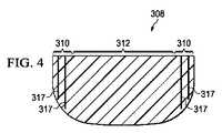
周縁マニホルド部材110と内側マニホルド部材112を同じ材料ではあるが、周縁マニホルド部材110の方をより高い密度(ρ)で作ることに加えて、周縁マニホルド部材110と内側マニホルド部材112を、より高い密度あるいはより大きい体積弾性率によって周縁マニホルド部材110がより高い高度を有するように選択して、異なる材料で作るようにしてもよい。更に、あるいは代替的に、図4に示すように、周縁マニホルド部材310を形成するときに第1のマニホルド材に支持エレメント317(例えば、フィラメント、垂直ポスト、支柱、その他の部材)を追加して、周縁マニホルド部材310の圧縮率をより低くしてもよい。支持エレメント317を追加することによって、複合型マニホルド308の周縁マニホルド部材310と内側マニホルド部材312を同じマニホルド材で作ることができるが、周縁マニホルド部材310が支持エレメントによって潰れに対抗するより高い強度を持つことになる。
代替的に、あるいは追加で、マニホルド材にバイオフレンドリィな硬化剤を吹き付けて、周縁部分を内側部分よりも硬くするとともに、周縁部分の流体マニホルド能力を維持するようにしてもよい。このようにして、周縁マニホルド部材110と内側マニホルド部材112とを形成する。受けるマニホルド材が流体をマニホルドあるいは供給し続けるものであれば、適宜のバイオフレンドリーな硬化剤を使用することができる。一例は、速効性の硬化ポリウレタンスプレィである。更に別の実施例においては、周縁マニホルド部材110は、スプレィあるいはジェルとして創傷エッジ109に直接適用して、インサイチュウで周縁マニホルド部材110を形成し、次いで、内側マニホルド部材112を形成する内部部分にマニホルド部材を展開させるようにしても良い。 Alternatively or additionally, a bio-friendly hardener may be sprayed onto the manifold material to make the peripheral portion harder than the inner portion and maintain the fluid manifold capability of the peripheral portion. In this manner, the
周縁マニホルド部材110を内部部分115と共に形成して、その中に取り込む内側マニホルド部材112を内側部分115の近傍に配置することができる。周縁マニホルド部材110と内側マニホルド部材112は、それ以外のものは無い状態で互いに隣接して配置されるか、あるいは粘着剤、接着剤、溶着、その他の手段によって互いに連結して、一体的ユニットとして形成してもよい。周縁マニホルド部材110と内側マニホルド部材112は、スペースをあけて、あるいは一又はそれ以上の要素によって別体としても良い。ここで用いられているように、用語「連結」は、別の物体を介した連結と、直接の連結を含む。用語「連結」は、同じ材料片でできている各構成要素によって、互いに連続している二又はそれ以上の構成要素にも及ぶ。また用語「連結」は、化学的接着剤を介するなどの化学的、機械的、熱的、あるいは電気的連結を含む。 A
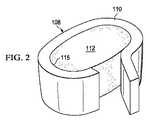
図1Aと図1Bに示すように、複合型マニホルド108は互いに隣接して配置された別々の部材でできており、周縁マニホルド部材110と内側マニホルド部材112とを作る別々の垂直エリアを形成するものでもよい。更に、図2に示唆されているように、周縁マニホルド部材110は、創傷102にサイズを合わせたマニホルドストリップあるいはテープであってもよく、創傷エッジ109に対して創傷に配置される。同時に、内側マニホルド部材112は、適宜のサイズで創傷102に配置して、複合型マニホルド108を形成するようにしてもよい。同様に、周縁マニホルド部材110をマニホルドストリップあるいはテープにする場合は、内側マニホルド112はほぼ創傷102のサイズであり、そのように構成されており、次いで、内側マニホルド部材112の周囲にマニホルドストリップあるいはテープを固定して、複合型マニホルド108を形成するようにしてもよい。一の実施例では、周縁マニホルド部材110自体が一体化されたものであるか、あるいは複数のマニホルド部材から形成されたものでもよい。 As shown in FIGS. 1A and 1B, the
複合型マニホルド108を作るその他の方法は数多くある。別の実施例として、図3は、壁214とベース216を具え、内側マニホルド部材212と共働するようになっている周縁マニホルド部材210を有する、複合型マニホルド208を示す。ベース216は、その中に形成した開口を有しており、このベース216を通る流体の流れをさらに促進する。周縁マニホルド部材210は、その中に内側マニホルド部材212を配置する内部部分215を規定する。周縁マニホルド部材210と内側マニホルド部材212は連結されていなくても良いが、入れ子式になっているか、あるいは連結されていても良い。更に、周縁マニホルド部材210と内側マニホルド部材212は、特性が変わる一体的なユニットとして形成されてもよい。代替として、内側マニホルド部材212は、周縁マニホルド部材210の上部に配置した複数のマニホルド機能を有する球体あるいはビーズとして形成することができる。作り方にかかわらず、複合型マニホルド108は、周縁マニホルド部材210が、創傷エッジに圧縮力がかからないように形成されており、一の実施例においては減圧下で、図に示す方向に対して少なくとも下向きに、内側マニホルド部材212よりも少なく圧縮するようになっている。 There are many other ways to make
生物活性物質を周縁マニホルド部材110、210に加えて、創傷エッジ(例えば、図1における創傷エッジ109)への治療と治癒を支援するようにしてもよい。生物活性物質の例には、エピネフリン(又はその他の拡張剤);血管拡張剤、あるいはトロンボキサンA2、プロスタグランジン2a、プロスタグランジン2−アルファ、フィブロネクチン、フィブリノゲン、フォン・ヴィレブランド病因子などの出血関連物質;ヒスタミンなどの血管拡張物質;血小板由来の成長因子、表皮増殖因子などのケモカイン関連物質;変性成長因子、表皮成長因子、インスリン様成長因子、角化細胞成長因子などの細胞増殖関連物質;及びリドカイン、発赤剤、カプサイシン、非ステロイド抗炎症剤(NSAID)、などの鎮痛剤;その他が含まれる。生物活性物質は、内側マニホルド部材112に加えてもよい。 Bioactive agents may be added to the peripheral
図1A及び図1Bを参照すると、シーリング部材111は複合型マニホルド108を覆っていて、複合型マニホルド108の周縁エッジ114を越えて延在してシーリング部材拡張部116を形成している。このシーリング部材拡張部116は、第一の側部118と、患者に対向する第二の側部120とを具える。シーリング部材拡張部116は、表皮103あるいはガスケット又はドレープに対して、感圧粘着材126などのシーリング装置124によって密封されている。このシーリング装置124は、粘着性シーリングテープ、ドレープテープ又はストリップ;両面ドレープテープ;感圧粘着材126;のり;親水コロイド;ヒドロゲル;あるいはその他シーリング手段など、様々な形態を採ることができる。テープを使う場合は、このテープはシーリング部材111と同じ材料でできていて、感圧粘着材が先付けされている。感圧粘着材126は、シーリング部材拡張部116の患者に対向する第二の側部120に塗布することができる。感圧式粘着材126は、シーリング部材111と上皮103との間を実質的に液密とし、ここで用いられているように、上皮103に対するガスケットあるいはドレープを具えるものとみなされる。シーリング部材111を上皮に固定する前に、感圧粘着材126を覆っている剥離式のストリップを取り除く。ここで使われている「液密」又は「密封」は、特定の減圧源又は減圧サブシステムによって与えられる減圧を所望の部位で維持するのに適した密封を意味する。 Referring to FIGS. 1A and 1B, the sealing
シーリング部材111は、エラストマーの材料、あるいは液密を提供する材料又は物質である。「エラストマーの」とは、エラストマーの性質を持っていることを意味し、一般的にはゴムのような特性を有するポリマー材を意味する。より具体的には、殆どのエラストマーは伸展度が100%以上であり、相当の回復力がある。材料の回復力とは、その材料の弾性変形からの回復する能力を意味する。エラストマーの例には、限定されるものではないが、天然ゴム、ポリイソプレン、スチレン・ブタジエンゴム、クロロプレンゴム、ポリブタジエン、ニトリルゴム、ブチルゴム、エチレン・プロピレンゴム、エチレン・プロピレン・ジエンモノマー、クロロスルホネート・ポリエチレン、ポリスルフィドゴム、ポリウレタン、EVAフィルム、共ポリエステル、そしてシリコーンが含まれる。更に、シーリング部材の素材には、シリコーン・ドレープ、3M社製 Tegaderm(登録商標)ドレープ、Avery Dennison社から入手可能なアクリル・ドレープ、あるいは切りこみ付ドレープが含まれる。 The sealing
減圧サブシステム113は、減圧源140を具えており、この減圧源は様々形をとることができる。この減圧源140は、減圧治療システム100の一部として減圧を供給する。ここで用いられているように、「減圧」は、一般的に、治療を行っている組織部位104における周囲圧力よりも低い圧力を意味する。殆どの場合において、この減圧は患者がいる場所の大気圧よりも低い。代替的に、減圧は組織部位において静水圧よりも低い圧力でもよい。減圧は、まず、マニホルド112、送達導管144、組織部位104近傍に流体の流れを作る。組織部位104周囲の静水圧が所望の減圧に近づくと、この流れが弱まり、減圧が維持される。特に記載がなければ、ここで述べる圧力の値はゲージ圧である。 The
送達した減圧は、一定であるか、又は変動し(パターンで、又はランダムに)、連続的又は間欠的に送達される。「真空」及び「負圧」の用語を用いて、組織部位に適用した圧力を表わすことができるが、組織部位に適用される実際の圧力は、通常完全な真空状態に関連する圧力よりも高い圧力でもよい。この用法に合わせると、減圧又は真空圧における増加は、一般的に、絶対圧における相対的低下を意味する。 The delivered vacuum is either constant or varies (in a pattern or randomly) and is delivered continuously or intermittently. The terms “vacuum” and “negative pressure” can be used to describe the pressure applied to the tissue site, but the actual pressure applied to the tissue site is usually higher than the pressure associated with a full vacuum condition. Pressure may be used. Consistent with this usage, an increase in vacuum or vacuum generally means a relative decrease in absolute pressure.
図1A及び1Bに示す実施例を参照すると、減圧源140は、リザーバ領域142又はキャニスタ領域を有するものとして示されている。疎水性あるいは親油性の介在膜フィルターが、送達導管144又はチューブと減圧源140との間に散在している。送達導管144の一部分146は、代表的なデバイス148などの一又はそれ以上のデバイスを有する。このデバイス148は、例えば、別の流体リザーバ、又は滲出液や取り除いたその他の流体を溜める回収部材、圧力フィードバック・デバイス、体積検出システム、血液検出システム、感染検出システム、流量監視システム、温度監視システムなどであり、複合デバイス148も含まれる。これらデバイスの幾つかは、減圧源140と一体的に形成されていてもよい。例えば、減圧源140の減圧ポート141は、臭気フィルターなどの一又はそれ以上のフィルターを具えるフィルター部材を具えていてもよい。 Referring to the embodiment shown in FIGS. 1A and 1B, the reduced
減圧源140は、真空ポンプや壁面吸引、あるいはその他の源といった、減圧を供給する何らかのデバイスである。組織部位に適用される減圧の量と性質は、通常、アプリケーションによって変化するが、この減圧は通常−5mmHg乃至−500mmHgの間であり、より具体的には、−100mmHg乃至−200mmHgの間の治療範囲にある。 The reduced
減圧源140によって生じた減圧は、送達導管144を経て、エルボ型ポート152を具える減圧インターフェース150に送達される。一の実施例においては、このエルボ型ポート152は、テキサス州サン・アントニオ市のキネティック・コンセプト社で入手できるTRAC(登録商標)テクノロジーポートである。減圧インターフェース150によって、シーリング部材111を経て複合型マニホルド108に減圧が送達され、同様に、複合型マニホルド108が設置されている密封空間154にも送達される。この実施例では、減圧インターフェース150は、シーリング部材111を通って複合型マニホルド108へ延在している。 The reduced pressure generated by the reduced
一の実施例による動作では、複合型マニホルド108は、例えば創傷102上の創傷床内などの組織部位104に、創傷エッジ109の近傍あるいは近位側にある周縁マニホルド部材110と共に、配置されている。複合型マニホルド108の一部としてテープ状周縁マニホルド部材110を使用する場合は、このテープ状周縁マニホルド部材110は非コイル状になって、創傷102の創傷周縁あるいは創傷エッジ109を追跡し、次いで、適宜のサイズの内側マニホルド112が、周縁マニホルド部材110によって規定された中央部分に入るようなサイズとなる。代替的に、内側マニホルド部材112が創傷102の大きさとほぼ合致するようなサイズとして(周縁マニホルド部材110用の小さな間隙を持たせて)、次いで、内側マニホルド部材112の周縁にテープを配置して、複合型マニホルド108を形成するようにしてもよい。 In operation according to one embodiment, the
次いで、組織部位104と複合型マニホルド108、及び上皮103(あるいはガスケットもしくはドレープ)の少なくとも一部分にシーリング部材111を配置して、流体シールを形成し、密封した空間154を形成する。もし減圧インターフェース150が設置されていなければ、設置する。送達導管144は減圧インターフェース150と減圧源140とに流体連結され、これによって減圧が複合型マニホルド108に送達される。減圧源140は、密封した空間154にある複合型マニホルド108に減圧の送達を開始するよう作動する。 The sealing
減圧が複合型マニホルド108に供給されると、複合型マニホルド108は、圧縮されていない状態(図1A)から圧縮された状態(図1B)へ圧縮される。図1Bに示すように、減圧下でも、より硬い周縁マニホルド部材110は潰れず、これがなければ創傷102又は組織部位104の減圧治療中に、シーリング部材111によって創傷エッジ109にかかるであろう負荷を担うことができる。図1Bに示す実施例では、周縁マニホルド部材110が内側マニホルド部材112と同じように圧縮せず、硬さが低い内側マニホルド部材112は、患者の動きを容易にして快適なものにする。 When reduced pressure is supplied to the
システム100によって、創傷のマージンあるいは創傷エッジにおいて加圧を最小限に抑えて減圧治療を行うことができ、損傷を最小限に抑える、あるいは防ぐことができる。システム100によって、生物活性因子を創傷エッジ109に容易に適用できる。 The
図に示す実施例は、複合型マニホルド108、208の個別部分(例えば、周縁マニホルド部材110と内側マニホルド部材112)を表わしているが、部分間で段階的な変更を行うことができる、又は、支持エレメントと共に単一片の材料を使用することができると、理解するべきである。周縁マニホルド部材110は、内側マニホルド部材112の延在する厚さとして示されているが、別の実施例においては、周縁マニホルド部材110は単に内側マニホルド部材112の上部にある(図1Aの方向で)。 The illustrated embodiment represents a separate portion of the
本発明とその利点を、図に示す非限定的な実施例のコンテキストで開示したが、特許請求の範囲によって定義される本発明の範囲から逸脱することなく、様々な変更、追加、置換、代替が可能であると理解すべきである。いずれかの実施例に関連して記述された特徴は、他の実施例に対しても適用可能であることは自明である。
While the invention and its advantages have been disclosed in the context of the non-limiting examples shown in the drawings, various modifications, additions, substitutions and alternatives may be made without departing from the scope of the invention as defined by the claims. Should be understood to be possible. It will be appreciated that the features described in connection with any embodiment are applicable to other embodiments.
Claims (33)
Translated fromJapanese複合型マニホルドであって、創傷エッジに隣接して配置し、内側部分を有する周縁マニホルド部材と、前記周縁マニホルド部材の前記内側部分に隣接して配置された内側マニホルド部材と、を具える複合型マニホルドと;
患者の上皮に連結し、前記創傷の上に流体シールを形成するよう動作するシーリング部材と;
前記複合型マニホルドに減圧を提供する減圧サブシステムと;を具え、
前記周縁マニホルド部材が、治療用減圧下にあるときに、前記シーリング部材によって伝達された圧縮力の下でも潰れない相応の強度をもって形成されていることを特徴とする減圧治療システム。In a reduced pressure therapy system for treating a patient's wound, the reduced pressure therapy system includes:
A composite manifold comprising a peripheral manifold member disposed adjacent to a wound edge and having an inner portion; and an inner manifold member disposed adjacent to the inner portion of the peripheral manifold member. With manifold;
A sealing member coupled to the patient's epithelium and operative to form a fluid seal over the wound;
A decompression subsystem for providing decompression to the composite manifold;
The reduced pressure treatment system according to claim 1, wherein the peripheral manifold member is formed with an appropriate strength so as not to be crushed even under a compressive force transmitted by the sealing member when the peripheral manifold member is under a reduced pressure for treatment.
前記周縁マニホルド部材が第1の体積弾性率K1を有し;
前記内側マニホルド部材が第2の体積弾性率K2を有し;
前記第1の体積弾性率K1が前記第2の体積弾性率K2よりも大きい;
ことを特徴とする複合型マニホルド。The composite manifold of claim 1:
The peripheral manifold member has a first bulk modulus K1 ;
The inner manifold member has a second bulk modulus K2 ;
The first bulk modulus K1 is greater than the second bulk modulus K2 ;
This is a composite manifold.
前記周縁マニホルド部材は第1の体積弾性率K1を有し;
前記内側マニホルド部材は第2の体積弾性率K2を有し;
前記第1の体積弾性率K1が前記第2の体積弾性率K2よりも大きく;
前記周縁マニホルド部材が前記内側マニホルド部材に連結されている;
ことを特徴とする複合型マニホルド。The composite manifold of claim 1:
The peripheral manifold member has a first bulk modulus K1 ;
The inner manifold member has a second bulk modulus K2 ;
The first bulk modulus K1 is greater than the second bulk modulus K2 ;
The peripheral manifold member is coupled to the inner manifold member;
This is a composite manifold.
前記周縁マニホルド部材が第1の密度ρ1を有し;
前記内側マニホルド部材が第2の密度ρ2を有し;
前記第1の密度ρ1が前記第2の密度ρ2よりも大きい;
ことを特徴とする複合型マニホルド。The composite manifold of claim 1:
The peripheral manifold member has a first density ρ1 ;
The inner manifold member has a second density ρ2 ;
The first density ρ1 is greater than the second density ρ2 ;
This is a composite manifold.
創傷エッジに隣接して配置され、内側部分を有する周縁マニホルド部材と;
前記周縁マニホルド部材の内側部分に隣接して配置された内側マニホルド部材と;を具え、
前記周縁マニホルド部材が、治療用減圧下にあるときに潰れない相応の強度をもって形成されていることを特徴とする複合型マニホルド。In a composite manifold for use in a reduced pressure treatment system, the composite manifold includes:
A peripheral manifold member disposed adjacent to the wound edge and having an inner portion;
An inner manifold member disposed adjacent to an inner portion of the peripheral manifold member;
A composite manifold, wherein the peripheral manifold member is formed with a strength that does not collapse when under a therapeutic vacuum.
前記周縁マニホルド部材が第1の体積弾性率K1を有し;
内側マニホルド部材が第2の体積弾性率K2を有し;
前記第1の体積弾性率K1が前記第2の体積弾性率K2よりも大きい;
ことを特徴とする複合型マニホルド。12. A composite manifold according to claim 11:
The peripheral manifold member has a first bulk modulus K1 ;
The inner manifold member has a second bulk modulus K2 ;
The first bulk modulus K1 is greater than the second bulk modulus K2 ;
This is a composite manifold.
前記周縁マニホルド部材が第1の体積弾性率K1を有し;
前記内側マニホルド部材が第2の体積弾性率K2を有し;
前記第1の体積弾性率K1が前記第2の体積弾性率K2よりも大きく;
前記周縁マニホルド部材が前記内側マニホルド部材と連結されている;
ことを特徴とする複合型マニホルド。12. A composite manifold according to claim 11:
The peripheral manifold member has a first bulk modulus K1 ;
The inner manifold member has a second bulk modulus K2 ;
The first bulk modulus K1 is greater than the second bulk modulus K2 ;
The peripheral manifold member is coupled to the inner manifold member;
This is a composite manifold.
前記周縁マニホルド部材が第1の密度ρ1を有し;
前記内側マニホルド部材が第2の密度ρ2を有し;
前記第1の密度ρ1が前記第2の密度ρ2よりも大きい;
ことを特徴とする複合型マニホルド。In the composite manifold of claim 11,
The peripheral manifold member has a first density ρ1 ;
The inner manifold member has a second density ρ2 ;
The first density ρ1 is greater than the second density ρ2 ;
This is a composite manifold.
創傷エッジに隣接して配置する周縁マニホルド部材を形成し、当該周縁マニホルドを内側部分を有するように形成するステップと;
内側マニホルド部材を形成するステップと;
前記周縁マニホルド部材の内側部分に隣接して前記周辺マニホルド部材を配置するステップと;を具え、
前記周縁マニホルド部材が、治療用減圧下にあるときに潰れない相応の強度をもって形成されていることを特徴とする複合型マニホルドの製造方法。In a method of manufacturing a composite manifold for use in a reduced pressure treatment system, the method includes:
Forming a peripheral manifold member for placement adjacent to the wound edge and forming the peripheral manifold with an inner portion;
Forming an inner manifold member;
Positioning the peripheral manifold member adjacent an inner portion of the peripheral manifold member;
A method of manufacturing a composite manifold, wherein the peripheral manifold member is formed with an appropriate strength that does not collapse when under reduced pressure for treatment.
第1の体積弾性率K1を持つ周縁マニホルド部材を形成するステップと;
第2の体積弾性率K2を持つ内側マニホルド部材を形成するステップ;を具え、
前記第1の体積弾性率K1が前記第2の体積弾性率K2よりも大きい;
ことを特徴とする複合型マニホルドの製造方法。20. The method of claim 19, wherein forming the peripheral manifold member and forming the inner manifold:
Forming a peripheral manifold member having afirst bulk modulus K1 ;
Forming an inner manifold member having asecond bulk modulus K2 ;
The first bulk modulus K1 is greater than the second bulk modulus K2 ;
A method of manufacturing a composite manifold.
第1の密度ρ1を持つ第1のマニホルド材で周縁マニホルド部材を形成するステップと;
第2の密度ρ2を持つ第2のマニホルド材で内側マニホルド部材を形成するステップ;を具え、
前記第1の密度ρ1が前記第2の密度ρ2よりも大きい;
ことを特徴とする複合型マニホルドの製造方法。20. The method of claim 19, wherein forming the peripheral manifold member and forming the inner manifold:
Forming a peripheral manifold member with a first manifold material having afirst density ρ1 ;
Forming an inner manifold member with a second manifold material having asecond density [rho]2 ;
The first density ρ1 is greater than the second density ρ2 ;
A method of manufacturing a composite manifold.
複合型マニホルドを創傷部位に隣接して配置するステップと;
前記複合型マニホルドの上に流体シールを形成するステップと;
減圧源を前記複合型マニホルドに流体連結するステップと;を具え、
前記複合型マニホルドが:
前記創傷エッジに隣接して配置され、内側部分を有する周縁マニホルド部材と;
前記周縁マニホルド部材の内側部分に隣接して配置された内側マニホルド部材と;を具え、
前記周縁マニホルド部材が、治療用減圧下にあるときに潰れない相応の強度をもって形成されていることを特徴とする治療方法。In a method of treating a patient's wound using reduced pressure, the method includes:
Positioning the composite manifold adjacent to the wound site;
Forming a fluid seal on the composite manifold;
Fluidly connecting a reduced pressure source to the composite manifold;
The composite manifold is:
A peripheral manifold member disposed adjacent to the wound edge and having an inner portion;
An inner manifold member disposed adjacent to an inner portion of the peripheral manifold member;
A method of treatment characterized in that the peripheral manifold member is formed with an appropriate strength that does not collapse when under reduced pressure for treatment.
前記周縁マニホルド部材が第1の体積弾性率K1を有し;
前記内側マニホルド部材が第2の体積弾性率K2を有し;
前記第1の体積弾性率K1が前記第2の体積弾性率K2よりも大きい;
ことを特徴とする治療方法。26. The method of treatment of claim 25:
The peripheral manifold member has a first bulk modulus K1 ;
The inner manifold member has a second bulk modulus K2 ;
The first bulk modulus K1 is greater than the second bulk modulus K2 ;
The treatment method characterized by the above-mentioned.
前記周縁マニホルド部材が第1の体積弾性率K1を有し;
前記内側マニホルド部材が第2の体積弾性率K2を有し;
前記第1の体積弾性率K1が前記第2の体積弾性率K2よりも大きく;
前記周縁マニホルド部材が内側マニホルド部材に連結されている;
ことを特徴とする治療方法。26. The method of treatment of claim 25:
The peripheral manifold member has a first bulk modulus K1 ;
The inner manifold member has a second bulk modulus K2 ;
The first bulk modulus K1 is greater than the second bulk modulus K2 ;
The peripheral manifold member is coupled to an inner manifold member;
The treatment method characterized by the above-mentioned.
前記周縁マニホルド部材が第1の密度ρ1を有し;
前記内側マニホルド部材が第2の密度ρ2を有し;
前記第1の密度ρ1が前記第2の密度ρ2よりも大きい;
ことを特徴とする治療方法。26. The method of treatment of claim 25:
The peripheral manifold member has a first density ρ1 ;
The inner manifold member has a second density ρ2 ;
The first density ρ1 is greater than the second density ρ2 ;
The treatment method characterized by the above-mentioned.
創傷エッジ近傍に配置する周縁マニホルド部材と;
前記周縁マニホルド部材に隣接して配置する内側マニホルド部材と;を具え、
前記周縁マニホルド部材が前記内側マニホルド部材よりも圧縮しにくいことを特徴とする複合型マニホルド。
In a composite manifold for use in a reduced pressure treatment system, the composite manifold includes:
A peripheral manifold member positioned near the wound edge;
An inner manifold member disposed adjacent to the peripheral manifold member;
The composite manifold, wherein the peripheral manifold member is harder to compress than the inner manifold member.
Applications Claiming Priority (3)
| Application Number | Priority Date | Filing Date | Title |
|---|---|---|---|
| US11576308P | 2008-11-18 | 2008-11-18 | |
| US61/115,763 | 2008-11-18 | ||
| PCT/US2009/064763WO2010059612A2 (en) | 2008-11-18 | 2009-11-17 | Reduced-pressure, composite manifolds |
Related Child Applications (1)
| Application Number | Title | Priority Date | Filing Date |
|---|---|---|---|
| JP2014191250ADivisionJP5936210B2 (en) | 2008-11-18 | 2014-09-19 | Composite manifold for decompression |
Publications (2)
| Publication Number | Publication Date |
|---|---|
| JP2012509108Atrue JP2012509108A (en) | 2012-04-19 |
| JP5620917B2 JP5620917B2 (en) | 2014-11-05 |
Family
ID=42172577
Family Applications (3)
| Application Number | Title | Priority Date | Filing Date |
|---|---|---|---|
| JP2011536594AExpired - Fee RelatedJP5620917B2 (en) | 2008-11-18 | 2009-11-17 | Composite manifold for decompression |
| JP2014191250AActiveJP5936210B2 (en) | 2008-11-18 | 2014-09-19 | Composite manifold for decompression |
| JP2016092335AActiveJP6313363B2 (en) | 2008-11-18 | 2016-05-02 | Composite manifold for decompression |
Family Applications After (2)
| Application Number | Title | Priority Date | Filing Date |
|---|---|---|---|
| JP2014191250AActiveJP5936210B2 (en) | 2008-11-18 | 2014-09-19 | Composite manifold for decompression |
| JP2016092335AActiveJP6313363B2 (en) | 2008-11-18 | 2016-05-02 | Composite manifold for decompression |
Country Status (12)
| Country | Link |
|---|---|
| US (3) | US8802916B2 (en) |
| EP (2) | EP2355762B1 (en) |
| JP (3) | JP5620917B2 (en) |
| KR (1) | KR20110095356A (en) |
| CN (2) | CN102215798B (en) |
| AU (2) | AU2009316796B2 (en) |
| BR (1) | BRPI0915250A2 (en) |
| CA (1) | CA2743727C (en) |
| MX (1) | MX2011005156A (en) |
| RU (1) | RU2011114003A (en) |
| TW (1) | TW201021868A (en) |
| WO (1) | WO2010059612A2 (en) |
Cited By (3)
| Publication number | Priority date | Publication date | Assignee | Title |
|---|---|---|---|---|
| JP2014516711A (en)* | 2011-05-25 | 2014-07-17 | ケーシーアイ ライセンシング インコーポレイテッド | Wound healing system using positive pressure to promote granulation in tissue sites |
| JP2015525647A (en)* | 2012-08-08 | 2015-09-07 | スミス アンド ネフュー ピーエルシーSmith & Nephew Public Limited Company | Custom wound treatment apparatus and method for use in negative pressure wound treatment |
| JP2016528964A (en)* | 2013-07-16 | 2016-09-23 | スミス アンド ネフュー ピーエルシーSmith & Nephew Public Limited Company | Apparatus and method for wound treatment |
Families Citing this family (78)
| Publication number | Priority date | Publication date | Assignee | Title |
|---|---|---|---|---|
| EP2214612B1 (en) | 2007-11-21 | 2019-05-01 | Smith & Nephew PLC | Wound dressing |
| ES2715605T3 (en) | 2007-11-21 | 2019-06-05 | Smith & Nephew | Wound dressing |
| GB0804654D0 (en) | 2008-03-13 | 2008-04-16 | Smith & Nephew | Vacuum closure device |
| GB0808376D0 (en) | 2008-05-08 | 2008-06-18 | Bristol Myers Squibb Co | Wound dressing |
| GB0817796D0 (en) | 2008-09-29 | 2008-11-05 | Convatec Inc | wound dressing |
| US8905983B2 (en)* | 2010-04-22 | 2014-12-09 | Kci Licensing, Inc. | System and method for utilizing exudate with a reduced pressure treatment system to generate electricity |
| GB201020236D0 (en) | 2010-11-30 | 2011-01-12 | Convatec Technologies Inc | A composition for detecting biofilms on viable tissues |
| US10207031B2 (en) | 2010-12-08 | 2019-02-19 | Convatec Technologies Inc. | Integrated system for assessing wound exudates |
| ES2748519T3 (en) | 2010-12-08 | 2020-03-17 | Convatec Technologies Inc | Wound exudate system accessory |
| WO2012078724A1 (en) | 2010-12-08 | 2012-06-14 | Convatec Technologies Inc. | Apparatus and method for applying pressure to a wound site |
| US9421132B2 (en) | 2011-02-04 | 2016-08-23 | University Of Massachusetts | Negative pressure wound closure device |
| AU2012212070A1 (en) | 2011-02-04 | 2013-09-19 | University Of Massachusetts | Negative pressure wound closure device |
| GB201115182D0 (en) | 2011-09-02 | 2011-10-19 | Trio Healthcare Ltd | Skin contact material |
| JP6202686B2 (en)* | 2011-11-18 | 2017-09-27 | ケーシーアイ ライセンシング インコーポレイテッド | Tissue treatment system and method having a porous substrate having a contraction region and an expansion region |
| GB2497406A (en) | 2011-11-29 | 2013-06-12 | Webtec Converting Llc | Dressing with a perforated binder layer |
| GB201120693D0 (en) | 2011-12-01 | 2012-01-11 | Convatec Technologies Inc | Wound dressing for use in vacuum therapy |
| JP6250571B2 (en) | 2012-03-12 | 2017-12-20 | スミス アンド ネフュー ピーエルシーSmith & Nephew Public Limited Company | Pressure reducing apparatus and method |
| EP2852419B1 (en) | 2012-05-22 | 2019-11-20 | Smith & Nephew plc | Wound closure device |
| EP2852333B1 (en) | 2012-05-22 | 2021-12-15 | Smith & Nephew plc | Apparatuses for wound therapy |
| AU2013264937B2 (en) | 2012-05-24 | 2018-04-19 | Smith & Nephew Inc. | Devices and methods for treating and closing wounds with negative pressure |
| MX369689B (en) | 2012-07-16 | 2019-11-19 | Smith & Nephew Inc | Negative pressure wound closure device. |
| JP2016507663A (en) | 2012-12-20 | 2016-03-10 | コンバテック・テクノロジーズ・インコーポレイテッドConvatec Technologies Inc | Processing of chemically modified cellulosic fibers |
| US10124098B2 (en) | 2013-03-13 | 2018-11-13 | Smith & Nephew, Inc. | Negative pressure wound closure device and systems and methods of use in treating wounds with negative pressure |
| BR112015021123A2 (en) | 2013-03-14 | 2017-07-18 | Smith & Nephew | compressible wound fillers and systems and methods for use in treating negative pressure injuries |
| CN106170275B (en) | 2013-10-21 | 2021-05-07 | 史密夫和内修有限公司 | Negative pressure wound closure device |
| US10946124B2 (en)* | 2013-10-28 | 2021-03-16 | Kci Licensing, Inc. | Hybrid sealing tape |
| EP3096725B1 (en) | 2014-01-21 | 2023-10-18 | Smith & Nephew plc | Wound treatment apparatuses |
| AU2015208299B2 (en) | 2014-01-21 | 2019-11-21 | Smith & Nephew Plc | Collapsible dressing for negative pressure wound treatment |
| DK3288508T3 (en) | 2015-04-27 | 2020-03-09 | Smith & Nephew | REDUCED PRESSURE DEVICES |
| AU2016254119A1 (en) | 2015-04-29 | 2017-10-05 | Smith & Nephew Inc. | Negative pressure wound closure device |
| GB2543544A (en) | 2015-10-21 | 2017-04-26 | Brightwake Ltd | Wound dressing |
| US10575991B2 (en) | 2015-12-15 | 2020-03-03 | University Of Massachusetts | Negative pressure wound closure devices and methods |
| US10814049B2 (en) | 2015-12-15 | 2020-10-27 | University Of Massachusetts | Negative pressure wound closure devices and methods |
| US11471586B2 (en) | 2015-12-15 | 2022-10-18 | University Of Massachusetts | Negative pressure wound closure devices and methods |
| EP3426206B1 (en) | 2016-03-07 | 2023-05-10 | Smith & Nephew plc | Wound treatment apparatuses and methods with negative pressure source integrated into wound dressing |
| PL3435941T3 (en) | 2016-03-30 | 2022-05-09 | Convatec Technologies Inc. | Detecting microbial infections in wounds |
| AU2017243601A1 (en) | 2016-03-30 | 2018-11-22 | Acib Gmbh | Detecting microbial infection in wounds |
| CA3022184A1 (en) | 2016-04-26 | 2017-11-02 | Smith & Nephew Plc | Wound dressings and methods of use with integrated negative pressure source having a fluid ingress inhibition component |
| WO2017191158A1 (en) | 2016-05-03 | 2017-11-09 | Smith & Nephew Plc | Systems and methods for driving negative pressure sources in negative pressure therapy systems |
| CA3038206A1 (en) | 2016-05-03 | 2017-11-09 | Smith & Nephew Plc | Optimizing power transfer to negative pressure sources in negative pressure therapy systems |
| US11096831B2 (en) | 2016-05-03 | 2021-08-24 | Smith & Nephew Plc | Negative pressure wound therapy device activation and control |
| MX2019000232A (en) | 2016-07-08 | 2019-11-12 | Convatec Technologies Inc | Fluid flow sensing. |
| EP3481348A4 (en) | 2016-07-08 | 2020-02-26 | ConvaTec Technologies Inc. | Fluid collection apparatus |
| DK3481349T3 (en) | 2016-07-08 | 2021-07-12 | Convatec Technologies Inc | Flexible vacuum system |
| WO2018037075A1 (en) | 2016-08-25 | 2018-03-01 | Smith & Nephew Plc | Absorbent negative pressure wound therapy dressing |
| JP7038701B2 (en) | 2016-08-30 | 2022-03-18 | スミス アンド ネフュー ピーエルシー | System for applying decompression therapy |
| US11096832B2 (en) | 2016-09-27 | 2021-08-24 | Smith & Nephew Plc | Wound closure devices with dissolvable portions |
| EP3519001B1 (en) | 2016-09-30 | 2025-05-21 | Smith & Nephew plc | Negative pressure wound treatment apparatuses and methods with integrated electronics |
| CN110167495B (en) | 2016-11-02 | 2022-06-14 | 史密夫和内修有限公司 | Wound closure device |
| EP3551244A1 (en) | 2016-12-12 | 2019-10-16 | Smith & Nephew PLC | Pressure wound therapy status indication via external device |
| EP3592312B1 (en) | 2017-03-08 | 2024-01-10 | Smith & Nephew plc | Negative pressure wound therapy device control in presence of fault condition |
| JP7121050B2 (en) | 2017-05-09 | 2022-08-17 | スミス アンド ネフュー ピーエルシー | Redundant control of negative pressure wound therapy systems |
| JP7204685B2 (en)* | 2017-06-07 | 2023-01-16 | スリーエム イノベイティブ プロパティズ カンパニー | A composite dressing that promotes granulation formation and reduces maceration in negative pressure therapy |
| EP3638169B1 (en) | 2017-06-13 | 2024-11-13 | Smith & Nephew PLC | Collapsible structure and method of use |
| WO2018229009A1 (en) | 2017-06-13 | 2018-12-20 | Smith & Nephew Plc | Wound closure device and method of use |
| US11123476B2 (en) | 2017-06-14 | 2021-09-21 | Smith & Nephew, Inc. | Fluid removal management and control of wound closure in wound therapy |
| WO2018229011A1 (en) | 2017-06-14 | 2018-12-20 | Smith & Nephew Plc | Collapsible structure for wound closure and method of use |
| AU2018285239B2 (en) | 2017-06-14 | 2023-09-21 | Smith & Nephew Plc | Collapsible sheet for wound closure and method of use |
| WO2018231874A1 (en) | 2017-06-14 | 2018-12-20 | Smith & Nephew, Inc. | Control of wound closure and fluid removal management in wound therapy |
| WO2019020544A1 (en) | 2017-07-27 | 2019-01-31 | Smith & Nephew Plc | Customizable wound closure device and method of use |
| US11590030B2 (en) | 2017-08-07 | 2023-02-28 | Smith & Nephew Plc | Wound closure device with protective layer and method of use |
| EP3675925A1 (en) | 2017-08-29 | 2020-07-08 | Smith & Nephew PLC | Systems and methods for monitoring wound closure |
| CA3074780A1 (en) | 2017-09-13 | 2019-03-21 | Smith & Nephew Plc | Negative pressure wound treatment apparatuses and methods with integrated electronics |
| GB201718070D0 (en) | 2017-11-01 | 2017-12-13 | Smith & Nephew | Negative pressure wound treatment apparatuses and methods with integrated electronics |
| RU2020113361A (en)* | 2017-09-20 | 2021-10-20 | Колопласт А/С | WOUND CARE DEVICE TO REMOVE DEAD TISSUE OF WOUNDS |
| US20210236342A1 (en)* | 2017-10-24 | 2021-08-05 | Kci Licensing, Inc. | Wound Dressings and Systems with Low-Flow Therapeutic Gas Sources for Topical Wound Therapy and Related Methods |
| GB201718072D0 (en) | 2017-11-01 | 2017-12-13 | Smith & Nephew | Negative pressure wound treatment apparatuses and methods with integrated electronics |
| US11497653B2 (en) | 2017-11-01 | 2022-11-15 | Smith & Nephew Plc | Negative pressure wound treatment apparatuses and methods with integrated electronics |
| GB201718054D0 (en) | 2017-11-01 | 2017-12-13 | Smith & Nephew | Sterilization of integrated negative pressure wound treatment apparatuses and sterilization methods |
| CN111836655A (en) | 2017-11-16 | 2020-10-27 | 康沃特克有限公司 | fluid collection equipment |
| EP3829515A1 (en)* | 2018-08-01 | 2021-06-09 | KCI Licensing, Inc. | Soft-tissue treatment with negative pressure |
| USD898925S1 (en) | 2018-09-13 | 2020-10-13 | Smith & Nephew Plc | Medical dressing |
| WO2020056014A1 (en)* | 2018-09-14 | 2020-03-19 | Kci Licensing, Inc. | Differential collapse wound dressings |
| GB201903774D0 (en) | 2019-03-20 | 2019-05-01 | Smith & Nephew | Negative pressure wound treatment apparatuses and methods with integrated electronics |
| GB201907716D0 (en) | 2019-05-31 | 2019-07-17 | Smith & Nephew | Systems and methods for extending operational time of negative pressure wound treatment apparatuses |
| EP4295869A3 (en) | 2019-06-03 | 2024-03-20 | Convatec Limited | Methods and devices to disrupt and contain pathogens |
| US11331221B2 (en) | 2019-12-27 | 2022-05-17 | Convatec Limited | Negative pressure wound dressing |
| US11771819B2 (en) | 2019-12-27 | 2023-10-03 | Convatec Limited | Low profile filter devices suitable for use in negative pressure wound therapy systems |
Citations (12)
| Publication number | Priority date | Publication date | Assignee | Title |
|---|---|---|---|---|
| US2280915A (en)* | 1941-04-03 | 1942-04-28 | John H Johnson | Device for irrigating and treating wounds |
| US2385207A (en)* | 1943-06-03 | 1945-09-18 | A D Morgan | Hemostat |
| US4206761A (en)* | 1976-06-21 | 1980-06-10 | Cosman Eric R | Pressure-balanced telemetric pressure sensing method |
| US5549584A (en)* | 1994-02-14 | 1996-08-27 | The Kendall Company | Apparatus for removing fluid from a wound |
| US20030212357A1 (en)* | 2002-05-10 | 2003-11-13 | Pace Edgar Alan | Method and apparatus for treating wounds with oxygen and reduced pressure |
| US20050148913A1 (en)* | 2004-01-02 | 2005-07-07 | Weston Richard S. | Reduced pressure wound treatment appliance |
| WO2007015964A1 (en)* | 2005-07-28 | 2007-02-08 | Integra Lifesciences Corporation | Laminar construction negative pressure wound dressing including bioabsorbable material |
| JP2007509682A (en)* | 2003-10-28 | 2007-04-19 | スミス アンド ネフュー ピーエルシー | Wound cleaning device using active ingredients |
| WO2007133618A2 (en)* | 2006-05-11 | 2007-11-22 | Iasis Medical, Llc | Device and method for wound therapy |
| WO2007133644A2 (en)* | 2006-05-11 | 2007-11-22 | Iasis Medical, Llc | Device and method for wound therapy |
| WO2007143060A2 (en)* | 2006-06-02 | 2007-12-13 | Kci Licensing Inc. | A wound suction peg apparatus |
| WO2008091521A2 (en)* | 2007-01-25 | 2008-07-31 | Kci Licensing Inc. | Biocompatible wound dressing |
Family Cites Families (156)
| Publication number | Priority date | Publication date | Assignee | Title |
|---|---|---|---|---|
| US1385346A (en)* | 1919-06-27 | 1921-07-19 | Taylor Walter Herbert | Surgical wound-dam |
| US1355846A (en)* | 1920-02-06 | 1920-10-19 | David A Rannells | Medical appliance |
| US2547758A (en)* | 1949-01-05 | 1951-04-03 | Wilmer B Keeling | Instrument for treating the male urethra |
| US2632443A (en)* | 1949-04-18 | 1953-03-24 | Eleanor P Lesher | Surgical dressing |
| GB692578A (en) | 1949-09-13 | 1953-06-10 | Minnesota Mining & Mfg | Improvements in or relating to drape sheets for surgical use |
| US2682873A (en)* | 1952-07-30 | 1954-07-06 | Johnson & Johnson | General purpose protective dressing |
| NL189176B (en)* | 1956-07-13 | 1900-01-01 | Hisamitsu Pharmaceutical Co | PLASTER BASED ON A SYNTHETIC RUBBER. |
| US2969057A (en)* | 1957-11-04 | 1961-01-24 | Brady Co W H | Nematodic swab |
| US3066672A (en) | 1960-09-27 | 1962-12-04 | Jr William H Crosby | Method and apparatus for serial sampling of intestinal juice |
| US3367332A (en)* | 1965-08-27 | 1968-02-06 | Gen Electric | Product and process for establishing a sterile area of skin |
| US3520300A (en)* | 1967-03-15 | 1970-07-14 | Amp Inc | Surgical sponge and suction device |
| US3568675A (en)* | 1968-08-30 | 1971-03-09 | Clyde B Harvey | Fistula and penetrating wound dressing |
| US3658692A (en)* | 1969-10-28 | 1972-04-25 | Exxon Research Engineering Co | Preparation of white oils with aluminum-alkyl activated iron group metal catalysts |
| US3682180A (en)* | 1970-06-08 | 1972-08-08 | Coilform Co Inc | Drain clip for surgical drain |
| BE789293Q (en) | 1970-12-07 | 1973-01-15 | Parke Davis & Co | MEDICO-SURGICAL DRESSING FOR BURNS AND SIMILAR LESIONS |
| US3826254A (en)* | 1973-02-26 | 1974-07-30 | Verco Ind | Needle or catheter retaining appliance |
| DE2527706A1 (en)* | 1975-06-21 | 1976-12-30 | Hanfried Dr Med Weigand | DEVICE FOR THE INTRODUCTION OF CONTRAST AGENTS INTO AN ARTIFICIAL INTESTINAL OUTLET |
| DE2640413C3 (en) | 1976-09-08 | 1980-03-27 | Richard Wolf Gmbh, 7134 Knittlingen | Catheter monitor |
| NL7710909A (en)* | 1976-10-08 | 1978-04-11 | Smith & Nephew | COMPOSITE STRAPS. |
| GB1562244A (en)* | 1976-11-11 | 1980-03-05 | Lock P M | Wound dressing materials |
| US4080970A (en)* | 1976-11-17 | 1978-03-28 | Miller Thomas J | Post-operative combination dressing and internal drain tube with external shield and tube connector |
| US4139004A (en)* | 1977-02-17 | 1979-02-13 | Gonzalez Jr Harry | Bandage apparatus for treating burns |
| US4184510A (en)* | 1977-03-15 | 1980-01-22 | Fibra-Sonics, Inc. | Valued device for controlling vacuum in surgery |
| US4165748A (en)* | 1977-11-07 | 1979-08-28 | Johnson Melissa C | Catheter tube holder |
| US4245637A (en)* | 1978-07-10 | 1981-01-20 | Nichols Robert L | Shutoff valve sleeve |
| SE414994B (en)* | 1978-11-28 | 1980-09-01 | Landstingens Inkopscentral | VENKATETERFORBAND |
| GB2047543B (en)* | 1978-12-06 | 1983-04-20 | Svedman Paul | Device for treating tissues for example skin |
| US4266545A (en) | 1979-04-06 | 1981-05-12 | Moss James P | Portable suction device for collecting fluids from a closed wound |
| US4284079A (en)* | 1979-06-28 | 1981-08-18 | Adair Edwin Lloyd | Method for applying a male incontinence device |
| US4261363A (en)* | 1979-11-09 | 1981-04-14 | C. R. Bard, Inc. | Retention clips for body fluid drains |
| US4569348A (en)* | 1980-02-22 | 1986-02-11 | Velcro Usa Inc. | Catheter tube holder strap |
| WO1981002516A1 (en)* | 1980-03-11 | 1981-09-17 | E Schmid | Cushion for holding an element of grafted skin |
| US4297995A (en)* | 1980-06-03 | 1981-11-03 | Key Pharmaceuticals, Inc. | Bandage containing attachment post |
| US4333468A (en)* | 1980-08-18 | 1982-06-08 | Geist Robert W | Mesentery tube holder apparatus |
| US4465485A (en)* | 1981-03-06 | 1984-08-14 | Becton, Dickinson And Company | Suction canister with unitary shut-off valve and filter features |
| US4392853A (en)* | 1981-03-16 | 1983-07-12 | Rudolph Muto | Sterile assembly for protecting and fastening an indwelling device |
| US4373519A (en)* | 1981-06-26 | 1983-02-15 | Minnesota Mining And Manufacturing Company | Composite wound dressing |
| US4392858A (en)* | 1981-07-16 | 1983-07-12 | Sherwood Medical Company | Wound drainage device |
| US4419097A (en) | 1981-07-31 | 1983-12-06 | Rexar Industries, Inc. | Attachment for catheter tube |
| AU550575B2 (en) | 1981-08-07 | 1986-03-27 | Richard Christian Wright | Wound drainage device |
| SE429197B (en)* | 1981-10-14 | 1983-08-22 | Frese Nielsen | SAR TREATMENT DEVICE |
| DE3146266A1 (en)* | 1981-11-21 | 1983-06-01 | B. Braun Melsungen Ag, 3508 Melsungen | COMBINED DEVICE FOR A MEDICAL SUCTION DRAINAGE |
| US4551139A (en) | 1982-02-08 | 1985-11-05 | Marion Laboratories, Inc. | Method and apparatus for burn wound treatment |
| US4475909A (en)* | 1982-05-06 | 1984-10-09 | Eisenberg Melvin I | Male urinary device and method for applying the device |
| EP0100148B1 (en) | 1982-07-06 | 1986-01-08 | Dow Corning Limited | Medical-surgical dressing and a process for the production thereof |
| NZ206837A (en) | 1983-01-27 | 1986-08-08 | Johnson & Johnson Prod Inc | Thin film adhesive dressing:backing material in three sections |
| US4548202A (en)* | 1983-06-20 | 1985-10-22 | Ethicon, Inc. | Mesh tissue fasteners |
| US4540412A (en)* | 1983-07-14 | 1985-09-10 | The Kendall Company | Device for moist heat therapy |
| US4543100A (en)* | 1983-11-01 | 1985-09-24 | Brodsky Stuart A | Catheter and drain tube retainer |
| US4525374A (en)* | 1984-02-27 | 1985-06-25 | Manresa, Inc. | Treating hydrophobic filters to render them hydrophilic |
| CA1286177C (en) | 1984-05-03 | 1991-07-16 | Smith And Nephew Associated Companies Plc | Adhesive wound dressing |
| US4897081A (en)* | 1984-05-25 | 1990-01-30 | Thermedics Inc. | Percutaneous access device |
| US5215522A (en)* | 1984-07-23 | 1993-06-01 | Ballard Medical Products | Single use medical aspirating device and method |
| GB8419745D0 (en)* | 1984-08-02 | 1984-09-05 | Smith & Nephew Ass | Wound dressing |
| US4872450A (en)* | 1984-08-17 | 1989-10-10 | Austad Eric D | Wound dressing and method of forming same |
| US4655754A (en)* | 1984-11-09 | 1987-04-07 | Stryker Corporation | Vacuum wound drainage system and lipids baffle therefor |
| US4826494A (en)* | 1984-11-09 | 1989-05-02 | Stryker Corporation | Vacuum wound drainage system |
| US4605399A (en)* | 1984-12-04 | 1986-08-12 | Complex, Inc. | Transdermal infusion device |
| US5037397A (en)* | 1985-05-03 | 1991-08-06 | Medical Distributors, Inc. | Universal clamp |
| US4640688A (en)* | 1985-08-23 | 1987-02-03 | Mentor Corporation | Urine collection catheter |
| US4710165A (en) | 1985-09-16 | 1987-12-01 | Mcneil Charles B | Wearable, variable rate suction/collection device |
| US4758220A (en)* | 1985-09-26 | 1988-07-19 | Alcon Laboratories, Inc. | Surgical cassette proximity sensing and latching apparatus |
| US4733659A (en)* | 1986-01-17 | 1988-03-29 | Seton Company | Foam bandage |
| EP0256060A1 (en) | 1986-01-31 | 1988-02-24 | OSMOND, Roger L. W. | Suction system for wound and gastro-intestinal drainage |
| US4838883A (en)* | 1986-03-07 | 1989-06-13 | Nissho Corporation | Urine-collecting device |
| JPS62281965A (en)* | 1986-05-29 | 1987-12-07 | テルモ株式会社 | Catheter and catheter fixing member |
| GB8621884D0 (en)* | 1986-09-11 | 1986-10-15 | Bard Ltd | Catheter applicator |
| GB2195255B (en) | 1986-09-30 | 1991-05-01 | Vacutec Uk Limited | Apparatus for vacuum treatment of an epidermal surface |
| US4743232A (en)* | 1986-10-06 | 1988-05-10 | The Clinipad Corporation | Package assembly for plastic film bandage |
| DE3634569A1 (en) | 1986-10-10 | 1988-04-21 | Sachse Hans E | CONDOM CATHETER, A URINE TUBE CATHETER FOR PREVENTING RISING INFECTIONS |
| JPS63135179A (en)* | 1986-11-26 | 1988-06-07 | 立花 俊郎 | Subcataneous drug administration set |
| GB8628564D0 (en) | 1986-11-28 | 1987-01-07 | Smiths Industries Plc | Anti-foaming agent suction apparatus |
| GB8706116D0 (en)* | 1987-03-14 | 1987-04-15 | Smith & Nephew Ass | Adhesive dressings |
| US4787888A (en) | 1987-06-01 | 1988-11-29 | University Of Connecticut | Disposable piezoelectric polymer bandage for percutaneous delivery of drugs and method for such percutaneous delivery (a) |
| US4863449A (en)* | 1987-07-06 | 1989-09-05 | Hollister Incorporated | Adhesive-lined elastic condom cathether |
| US5176663A (en)* | 1987-12-02 | 1993-01-05 | Pal Svedman | Dressing having pad with compressibility limiting elements |
| US4906240A (en)* | 1988-02-01 | 1990-03-06 | Matrix Medica, Inc. | Adhesive-faced porous absorbent sheet and method of making same |
| US4985019A (en)* | 1988-03-11 | 1991-01-15 | Michelson Gary K | X-ray marker |
| GB8812803D0 (en) | 1988-05-28 | 1988-06-29 | Smiths Industries Plc | Medico-surgical containers |
| US4919654A (en)* | 1988-08-03 | 1990-04-24 | Kalt Medical Corporation | IV clamp with membrane |
| US5000741A (en) | 1988-08-22 | 1991-03-19 | Kalt Medical Corporation | Transparent tracheostomy tube dressing |
| US5059596A (en)* | 1989-01-16 | 1991-10-22 | Roussel Uclaf | Azabicyclo compounds |
| GB8906100D0 (en) | 1989-03-16 | 1989-04-26 | Smith & Nephew | Laminates |
| US5100396A (en)* | 1989-04-03 | 1992-03-31 | Zamierowski David S | Fluidic connection system and method |
| US5261893A (en) | 1989-04-03 | 1993-11-16 | Zamierowski David S | Fastening system and method |
| US4969880A (en) | 1989-04-03 | 1990-11-13 | Zamierowski David S | Wound dressing and treatment method |
| US5527293A (en)* | 1989-04-03 | 1996-06-18 | Kinetic Concepts, Inc. | Fastening system and method |
| US5358494A (en)* | 1989-07-11 | 1994-10-25 | Svedman Paul | Irrigation dressing |
| JP2719671B2 (en)* | 1989-07-11 | 1998-02-25 | 日本ゼオン株式会社 | Wound dressing |
| US5232453A (en)* | 1989-07-14 | 1993-08-03 | E. R. Squibb & Sons, Inc. | Catheter holder |
| GB2235877A (en) | 1989-09-18 | 1991-03-20 | Antonio Talluri | Closed wound suction apparatus |
| US5134994A (en)* | 1990-02-12 | 1992-08-04 | Say Sam L | Field aspirator in a soft pack with externally mounted container |
| US5092858A (en)* | 1990-03-20 | 1992-03-03 | Becton, Dickinson And Company | Liquid gelling agent distributor device |
| JP2941918B2 (en) | 1990-09-19 | 1999-08-30 | テルモ株式会社 | Weighing device |
| US5149331A (en)* | 1991-05-03 | 1992-09-22 | Ariel Ferdman | Method and device for wound closure |
| US5278100A (en)* | 1991-11-08 | 1994-01-11 | Micron Technology, Inc. | Chemical vapor deposition technique for depositing titanium silicide on semiconductor wafers |
| US5636643A (en) | 1991-11-14 | 1997-06-10 | Wake Forest University | Wound treatment employing reduced pressure |
| US5645081A (en)* | 1991-11-14 | 1997-07-08 | Wake Forest University | Method of treating tissue damage and apparatus for same |
| US5279550A (en)* | 1991-12-19 | 1994-01-18 | Gish Biomedical, Inc. | Orthopedic autotransfusion system |
| US5167613A (en) | 1992-03-23 | 1992-12-01 | The Kendall Company | Composite vented wound dressing |
| FR2690617B1 (en)* | 1992-04-29 | 1994-06-24 | Cbh Textile | TRANSPARENT ADHESIVE DRESSING. |
| DE4306478A1 (en) | 1993-03-02 | 1994-09-08 | Wolfgang Dr Wagner | Drainage device, in particular pleural drainage device, and drainage method |
| US6241747B1 (en)* | 1993-05-03 | 2001-06-05 | Quill Medical, Inc. | Barbed Bodily tissue connector |
| US5342376A (en)* | 1993-05-03 | 1994-08-30 | Dermagraphics, Inc. | Inserting device for a barbed tissue connector |
| US5344415A (en)* | 1993-06-15 | 1994-09-06 | Deroyal Industries, Inc. | Sterile system for dressing vascular access site |
| US5437651A (en)* | 1993-09-01 | 1995-08-01 | Research Medical, Inc. | Medical suction apparatus |
| US5556375A (en)* | 1994-06-16 | 1996-09-17 | Hercules Incorporated | Wound dressing having a fenestrated base layer |
| US5607388A (en)* | 1994-06-16 | 1997-03-04 | Hercules Incorporated | Multi-purpose wound dressing |
| US5664270A (en) | 1994-07-19 | 1997-09-09 | Kinetic Concepts, Inc. | Patient interface system |
| DE69505545T2 (en) | 1994-08-22 | 1999-03-11 | Kinetic Concepts Inc | WOUND DRAINAGE DEVICE |
| DE29504378U1 (en) | 1995-03-15 | 1995-09-14 | MTG Medizinisch, technische Gerätebau GmbH, 66299 Friedrichsthal | Electronically controlled low-vacuum pump for chest and wound drainage |
| JPH0994808A (en)* | 1995-09-29 | 1997-04-08 | Alpha Techno Co Ltd | Method for reinforcing material damaged by termite |
| GB9523253D0 (en) | 1995-11-14 | 1996-01-17 | Mediscus Prod Ltd | Portable wound treatment apparatus |
| US6135116A (en)* | 1997-07-28 | 2000-10-24 | Kci Licensing, Inc. | Therapeutic method for treating ulcers |
| AU755496B2 (en) | 1997-09-12 | 2002-12-12 | Kci Licensing, Inc. | Surgical drape and suction head for wound treatment |
| GB9719520D0 (en) | 1997-09-12 | 1997-11-19 | Kci Medical Ltd | Surgical drape and suction heads for wound treatment |
| US6071267A (en)* | 1998-02-06 | 2000-06-06 | Kinetic Concepts, Inc. | Medical patient fluid management interface system and method |
| US6942650B1 (en)* | 1998-04-17 | 2005-09-13 | Innovative Surgical Technologies, Inc. | Evacuator |
| US6458109B1 (en)* | 1998-08-07 | 2002-10-01 | Hill-Rom Services, Inc. | Wound treatment apparatus |
| US6488643B1 (en) | 1998-10-08 | 2002-12-03 | Kci Licensing, Inc. | Wound healing foot wrap |
| US6287316B1 (en)* | 1999-03-26 | 2001-09-11 | Ethicon, Inc. | Knitted surgical mesh |
| US6856821B2 (en)* | 2000-05-26 | 2005-02-15 | Kci Licensing, Inc. | System for combined transcutaneous blood gas monitoring and vacuum assisted wound closure |
| US7799004B2 (en)* | 2001-03-05 | 2010-09-21 | Kci Licensing, Inc. | Negative pressure wound treatment apparatus and infection identification system and method |
| EP2255837B2 (en)* | 1999-04-09 | 2020-07-29 | KCI Licensing, Inc. | Process for making a porous pad for use in a wound therapy device |
| US6991643B2 (en)* | 2000-12-20 | 2006-01-31 | Usgi Medical Inc. | Multi-barbed device for retaining tissue in apposition and methods of use |
| ES2220734T3 (en) | 2000-02-24 | 2004-12-16 | Venetec International, Inc. | UNIVERSAL FIXING SYSTEM FOR CATETER. |
| GB0011202D0 (en)* | 2000-05-09 | 2000-06-28 | Kci Licensing Inc | Abdominal wound dressing |
| US7070584B2 (en)* | 2001-02-20 | 2006-07-04 | Kci Licensing, Inc. | Biocompatible wound dressing |
| US6540705B2 (en)* | 2001-02-22 | 2003-04-01 | Core Products International, Inc. | Ankle brace providing upper and lower ankle adjustment |
| US7004915B2 (en)* | 2001-08-24 | 2006-02-28 | Kci Licensing, Inc. | Negative pressure assisted tissue treatment system |
| EP1461113A4 (en)* | 2001-12-26 | 2009-05-06 | Hill Rom Services Inc | Wound vacuum therapy dressing kit |
| US7846141B2 (en) | 2002-09-03 | 2010-12-07 | Bluesky Medical Group Incorporated | Reduced pressure treatment system |
| GB0224986D0 (en) | 2002-10-28 | 2002-12-04 | Smith & Nephew | Apparatus |
| US7976519B2 (en)* | 2002-12-31 | 2011-07-12 | Kci Licensing, Inc. | Externally-applied patient interface system and method |
| GB0325126D0 (en) | 2003-10-28 | 2003-12-03 | Smith & Nephew | Apparatus with heat |
| US7909805B2 (en) | 2004-04-05 | 2011-03-22 | Bluesky Medical Group Incorporated | Flexible reduced pressure treatment appliance |
| GB0508531D0 (en)* | 2005-04-27 | 2005-06-01 | Smith & Nephew | Sai with ultrasound |
| US8529548B2 (en) | 2004-04-27 | 2013-09-10 | Smith & Nephew Plc | Wound treatment apparatus and method |
| DE102005007016A1 (en)* | 2005-02-15 | 2006-08-24 | Fleischmann, Wilhelm, Dr.med. | Device for the treatment of wounds |
| CA2619925A1 (en)* | 2005-09-07 | 2007-03-15 | Tyco Healthcare Group Lp | Wound dressing with vacuum reservoir |
| BRPI0616297A2 (en) | 2005-09-26 | 2016-08-23 | Coloplast As | foam bandage |
| US7601129B2 (en)* | 2005-12-15 | 2009-10-13 | Aalnex, Inc. | Wound shield and warming apparatus and method |
| AU2007212488B2 (en)* | 2006-02-07 | 2012-07-12 | Smith & Nephew Inc. | Surgical wound dressing |
| US20080014386A1 (en)* | 2006-06-01 | 2008-01-17 | Andover Healthcare, Inc. | Cohesive articles with a foam layer |
| US20080014251A1 (en)* | 2006-07-14 | 2008-01-17 | Advanced Vascular Dynamics | Hemostatic compound and its use |
| US7362575B2 (en)* | 2006-07-17 | 2008-04-22 | Sun Microsystems, Inc. | Cooling method use diamond pins and heat pipes |
| US9539373B2 (en)* | 2006-08-30 | 2017-01-10 | Southeastern Medical Technologies, Llc | Methods, compositions and apparatuses to treat wounds with pressures altered from atmospheric |
| EP1905465B2 (en)* | 2006-09-28 | 2013-11-27 | Smith & Nephew, Inc. | Portable wound therapy system |
| US20080243096A1 (en)* | 2006-10-05 | 2008-10-02 | Paul Svedman | Device For Active Treatment and Regeneration of Tissues Such as Wounds |
| US8030534B2 (en)* | 2006-11-28 | 2011-10-04 | Boehringer Technologies, L.P. | Tunnel dressing for use with negative pressure wound therapy system |
| CN200977228Y (en)* | 2006-12-15 | 2007-11-21 | 中国人民解放军第四军医大学 | Closed negative pressure wound surface dressings |
| CN201005866Y (en)* | 2006-12-28 | 2008-01-16 | 窦修平 | Wound depression blood-supply enhancement dressing |
| US8021347B2 (en) | 2008-07-21 | 2011-09-20 | Tyco Healthcare Group Lp | Thin film wound dressing |
| US8007481B2 (en) | 2008-07-17 | 2011-08-30 | Tyco Healthcare Group Lp | Subatmospheric pressure mechanism for wound therapy system |
| US8251979B2 (en) | 2009-05-11 | 2012-08-28 | Tyco Healthcare Group Lp | Orientation independent canister for a negative pressure wound therapy device |
| US8216198B2 (en) | 2009-01-09 | 2012-07-10 | Tyco Healthcare Group Lp | Canister for receiving wound exudate in a negative pressure therapy system |
- 2009
- 2009-11-17CNCN200980145316.7Apatent/CN102215798B/ennot_activeExpired - Fee Related
- 2009-11-17EPEP09828103.3Apatent/EP2355762B1/enactiveActive
- 2009-11-17BRBRPI0915250Apatent/BRPI0915250A2/ennot_activeIP Right Cessation
- 2009-11-17AUAU2009316796Apatent/AU2009316796B2/ennot_activeCeased
- 2009-11-17USUS12/620,086patent/US8802916B2/enactiveActive
- 2009-11-17RURU2011114003/14Apatent/RU2011114003A/enunknown
- 2009-11-17JPJP2011536594Apatent/JP5620917B2/ennot_activeExpired - Fee Related
- 2009-11-17CACA2743727Apatent/CA2743727C/ennot_activeExpired - Fee Related
- 2009-11-17MXMX2011005156Apatent/MX2011005156A/ennot_activeApplication Discontinuation
- 2009-11-17KRKR1020117013751Apatent/KR20110095356A/ennot_activeWithdrawn
- 2009-11-17WOPCT/US2009/064763patent/WO2010059612A2/enactiveApplication Filing
- 2009-11-17CNCN201410400067.4Apatent/CN104189964B/enactiveActive
- 2009-11-17EPEP19194943.7Apatent/EP3593775A1/enactivePending
- 2009-11-18TWTW098139151Apatent/TW201021868A/enunknown
- 2014
- 2014-06-30USUS14/320,234patent/US9713550B2/enactiveActive
- 2014-09-11AUAU2014224083Apatent/AU2014224083B2/ennot_activeCeased
- 2014-09-19JPJP2014191250Apatent/JP5936210B2/enactiveActive
- 2016
- 2016-05-02JPJP2016092335Apatent/JP6313363B2/enactiveActive
- 2017
- 2017-05-19USUS15/600,265patent/US10610415B2/enactiveActive
Patent Citations (15)
| Publication number | Priority date | Publication date | Assignee | Title |
|---|---|---|---|---|
| US2280915A (en)* | 1941-04-03 | 1942-04-28 | John H Johnson | Device for irrigating and treating wounds |
| US2385207A (en)* | 1943-06-03 | 1945-09-18 | A D Morgan | Hemostat |
| US4206761A (en)* | 1976-06-21 | 1980-06-10 | Cosman Eric R | Pressure-balanced telemetric pressure sensing method |
| US5549584A (en)* | 1994-02-14 | 1996-08-27 | The Kendall Company | Apparatus for removing fluid from a wound |
| US20030212357A1 (en)* | 2002-05-10 | 2003-11-13 | Pace Edgar Alan | Method and apparatus for treating wounds with oxygen and reduced pressure |
| JP2007509682A (en)* | 2003-10-28 | 2007-04-19 | スミス アンド ネフュー ピーエルシー | Wound cleaning device using active ingredients |
| US20050148913A1 (en)* | 2004-01-02 | 2005-07-07 | Weston Richard S. | Reduced pressure wound treatment appliance |
| WO2007015964A1 (en)* | 2005-07-28 | 2007-02-08 | Integra Lifesciences Corporation | Laminar construction negative pressure wound dressing including bioabsorbable material |
| WO2007133618A2 (en)* | 2006-05-11 | 2007-11-22 | Iasis Medical, Llc | Device and method for wound therapy |
| WO2007133644A2 (en)* | 2006-05-11 | 2007-11-22 | Iasis Medical, Llc | Device and method for wound therapy |
| JP2009536852A (en)* | 2006-05-11 | 2009-10-22 | カリプト メディカル インコーポレーション | Trauma treatment device and method |
| JP2009536851A (en)* | 2006-05-11 | 2009-10-22 | カリプト メディカル インコーポレーション | Trauma treatment device and method |
| WO2007143060A2 (en)* | 2006-06-02 | 2007-12-13 | Kci Licensing Inc. | A wound suction peg apparatus |
| WO2008091521A2 (en)* | 2007-01-25 | 2008-07-31 | Kci Licensing Inc. | Biocompatible wound dressing |
| JP2010516387A (en)* | 2007-01-25 | 2010-05-20 | ケーシーアイ ライセンシング インコーポレイテッド | Biocompatible wound dressing |
Cited By (3)
| Publication number | Priority date | Publication date | Assignee | Title |
|---|---|---|---|---|
| JP2014516711A (en)* | 2011-05-25 | 2014-07-17 | ケーシーアイ ライセンシング インコーポレイテッド | Wound healing system using positive pressure to promote granulation in tissue sites |
| JP2015525647A (en)* | 2012-08-08 | 2015-09-07 | スミス アンド ネフュー ピーエルシーSmith & Nephew Public Limited Company | Custom wound treatment apparatus and method for use in negative pressure wound treatment |
| JP2016528964A (en)* | 2013-07-16 | 2016-09-23 | スミス アンド ネフュー ピーエルシーSmith & Nephew Public Limited Company | Apparatus and method for wound treatment |
Also Published As
| Publication number | Publication date |
|---|---|
| AU2014224083B2 (en) | 2016-03-31 |
| CN102215798B (en) | 2014-09-10 |
| TW201021868A (en) | 2010-06-16 |
| EP2355762B1 (en) | 2019-09-25 |
| AU2009316796A1 (en) | 2010-05-27 |
| CN102215798A (en) | 2011-10-12 |
| US20140336603A1 (en) | 2014-11-13 |
| CN104189964B (en) | 2016-10-05 |
| BRPI0915250A2 (en) | 2019-09-10 |
| JP2015042258A (en) | 2015-03-05 |
| EP2355762A4 (en) | 2017-07-05 |
| US9713550B2 (en) | 2017-07-25 |
| US10610415B2 (en) | 2020-04-07 |
| JP5936210B2 (en) | 2016-06-22 |
| RU2011114003A (en) | 2012-12-27 |
| JP5620917B2 (en) | 2014-11-05 |
| CA2743727A1 (en) | 2010-05-27 |
| WO2010059612A2 (en) | 2010-05-27 |
| MX2011005156A (en) | 2011-05-30 |
| US20100125233A1 (en) | 2010-05-20 |
| CA2743727C (en) | 2017-04-11 |
| JP2016154929A (en) | 2016-09-01 |
| AU2009316796B2 (en) | 2014-06-19 |
| KR20110095356A (en) | 2011-08-24 |
| CN104189964A (en) | 2014-12-10 |
| US8802916B2 (en) | 2014-08-12 |
| AU2014224083A1 (en) | 2014-10-02 |
| JP6313363B2 (en) | 2018-04-18 |
| WO2010059612A3 (en) | 2010-09-16 |
| US20170252219A1 (en) | 2017-09-07 |
| EP3593775A1 (en) | 2020-01-15 |
| EP2355762A2 (en) | 2011-08-17 |
Similar Documents
| Publication | Publication Date | Title |
|---|---|---|
| JP6313363B2 (en) | Composite manifold for decompression | |
| US10744040B2 (en) | Reduced-pressure dressing assemblies for use in applying a closing force | |
| US9352075B2 (en) | Wound healing apparatus for promoting granulation and epithelialization at a tissue site | |
| CA2725569C (en) | Reduced-pressure, linear wound closing bolsters and systems | |
| KR20110056312A (en) | Methods, systems, and lamina dressings that exert a reduced pressure on tissue sites | |
| JP2012523915A (en) | Reduced pressure treatment system and method using variable cover |
Legal Events
| Date | Code | Title | Description |
|---|---|---|---|
| A521 | Request for written amendment filed | Free format text:JAPANESE INTERMEDIATE CODE: A523 Effective date:20120706 | |
| A131 | Notification of reasons for refusal | Free format text:JAPANESE INTERMEDIATE CODE: A131 Effective date:20121009 | |
| A131 | Notification of reasons for refusal | Free format text:JAPANESE INTERMEDIATE CODE: A131 Effective date:20130625 | |
| A521 | Request for written amendment filed | Free format text:JAPANESE INTERMEDIATE CODE: A523 Effective date:20130925 | |
| A521 | Request for written amendment filed | Free format text:JAPANESE INTERMEDIATE CODE: A523 Effective date:20131008 | |
| A131 | Notification of reasons for refusal | Free format text:JAPANESE INTERMEDIATE CODE: A131 Effective date:20131217 | |
| A521 | Request for written amendment filed | Free format text:JAPANESE INTERMEDIATE CODE: A523 Effective date:20140317 | |
| TRDD | Decision of grant or rejection written | ||
| A01 | Written decision to grant a patent or to grant a registration (utility model) | Free format text:JAPANESE INTERMEDIATE CODE: A01 Effective date:20140826 | |
| A61 | First payment of annual fees (during grant procedure) | Free format text:JAPANESE INTERMEDIATE CODE: A61 Effective date:20140919 | |
| R150 | Certificate of patent or registration of utility model | Ref document number:5620917 Country of ref document:JP Free format text:JAPANESE INTERMEDIATE CODE: R150 | |
| R250 | Receipt of annual fees | Free format text:JAPANESE INTERMEDIATE CODE: R250 | |
| R250 | Receipt of annual fees | Free format text:JAPANESE INTERMEDIATE CODE: R250 | |
| LAPS | Cancellation because of no payment of annual fees |