JP2012508838A - Use of self-regulating nuclear reactors in the treatment of surface subsurface layers. - Google Patents
Use of self-regulating nuclear reactors in the treatment of surface subsurface layers.Download PDFInfo
- Publication number
- JP2012508838A JP2012508838AJP2011531191AJP2011531191AJP2012508838AJP 2012508838 AJP2012508838 AJP 2012508838AJP 2011531191 AJP2011531191 AJP 2011531191AJP 2011531191 AJP2011531191 AJP 2011531191AJP 2012508838 AJP2012508838 AJP 2012508838A
- Authority
- JP
- Japan
- Prior art keywords
- formation
- self
- reactor
- regulating
- temperature
- Prior art date
- Legal status (The legal status is an assumption and is not a legal conclusion. Google has not performed a legal analysis and makes no representation as to the accuracy of the status listed.)
- Ceased
Links
- 230000015572biosynthetic processEffects0.000claimsabstractdescription273
- 229930195733hydrocarbonNatural products0.000claimsabstractdescription158
- 150000002430hydrocarbonsChemical class0.000claimsabstractdescription158
- 238000004519manufacturing processMethods0.000claimsabstractdescription44
- 230000002596correlated effectEffects0.000claimsabstractdescription8
- 238000010438heat treatmentMethods0.000claimsdescription84
- 238000011065in-situ storageMethods0.000claimsdescription74
- 239000013529heat transfer fluidSubstances0.000claimsdescription71
- 239000000463materialSubstances0.000claimsdescription29
- 150000003839saltsChemical class0.000claimsdescription23
- 229910052987metal hydrideInorganic materials0.000claimsdescription18
- 150000004681metal hydridesChemical class0.000claimsdescription18
- 239000011358absorbing materialSubstances0.000claimsdescription7
- 230000007423decreaseEffects0.000claimsdescription5
- 239000004215Carbon black (E152)Substances0.000abstractdescription85
- 238000000034methodMethods0.000abstractdescription76
- 238000012545processingMethods0.000abstractdescription28
- 238000005755formation reactionMethods0.000description250
- 239000012530fluidSubstances0.000description99
- 230000008569processEffects0.000description49
- UFHFLCQGNIYNRP-UHFFFAOYSA-NHydrogenChemical compound[H][H]UFHFLCQGNIYNRP-UHFFFAOYSA-N0.000description39
- 239000001257hydrogenSubstances0.000description39
- 229910052739hydrogenInorganic materials0.000description39
- 239000007789gasSubstances0.000description34
- 238000000197pyrolysisMethods0.000description33
- 238000006243chemical reactionMethods0.000description24
- 239000000446fuelSubstances0.000description22
- 239000010410layerSubstances0.000description21
- 230000005611electricityEffects0.000description20
- 239000001307heliumSubstances0.000description20
- 229910052734heliumInorganic materials0.000description20
- SWQJXJOGLNCZEY-UHFFFAOYSA-Nhelium atomChemical compound[He]SWQJXJOGLNCZEY-UHFFFAOYSA-N0.000description20
- XLYOFNOQVPJJNP-UHFFFAOYSA-NwaterSubstancesOXLYOFNOQVPJJNP-UHFFFAOYSA-N0.000description18
- 229910001868waterInorganic materials0.000description18
- VNWKTOKETHGBQD-UHFFFAOYSA-NmethaneChemical compoundCVNWKTOKETHGBQD-UHFFFAOYSA-N0.000description16
- CURLTUGMZLYLDI-UHFFFAOYSA-NCarbon dioxideChemical compoundO=C=OCURLTUGMZLYLDI-UHFFFAOYSA-N0.000description15
- 238000012546transferMethods0.000description13
- 239000008186active pharmaceutical agentSubstances0.000description12
- 239000004020conductorSubstances0.000description12
- 230000005484gravityEffects0.000description12
- 238000000605extractionMethods0.000description11
- 230000035699permeabilityEffects0.000description11
- 238000003860storageMethods0.000description11
- 230000004888barrier functionEffects0.000description10
- 150000004678hydridesChemical class0.000description10
- 239000007788liquidSubstances0.000description9
- 239000004058oil shaleSubstances0.000description9
- OKTJSMMVPCPJKN-UHFFFAOYSA-NCarbonChemical compound[C]OKTJSMMVPCPJKN-UHFFFAOYSA-N0.000description8
- 230000008901benefitEffects0.000description8
- 229910052799carbonInorganic materials0.000description8
- 150000001875compoundsChemical class0.000description8
- 238000010586diagramMethods0.000description8
- 238000002347injectionMethods0.000description8
- 239000007924injectionSubstances0.000description8
- 238000003786synthesis reactionMethods0.000description8
- 229910002092carbon dioxideInorganic materials0.000description7
- 239000001569carbon dioxideSubstances0.000description7
- 150000002431hydrogenChemical class0.000description7
- 230000006872improvementEffects0.000description7
- 239000000203mixtureSubstances0.000description7
- 239000003921oilSubstances0.000description7
- 238000011084recoveryMethods0.000description7
- IJGRMHOSHXDMSA-UHFFFAOYSA-NAtomic nitrogenChemical compoundN#NIJGRMHOSHXDMSA-UHFFFAOYSA-N0.000description6
- 239000010426asphaltSubstances0.000description6
- 238000013461designMethods0.000description6
- QGZKDVFQNNGYKY-UHFFFAOYSA-NAmmoniaChemical compoundNQGZKDVFQNNGYKY-UHFFFAOYSA-N0.000description5
- 238000002407reformingMethods0.000description5
- 239000007787solidSubstances0.000description5
- 239000000243solutionSubstances0.000description5
- VYPSYNLAJGMNEJ-UHFFFAOYSA-NSilicium dioxideChemical compoundO=[Si]=OVYPSYNLAJGMNEJ-UHFFFAOYSA-N0.000description4
- 239000010779crude oilSubstances0.000description4
- 238000005868electrolysis reactionMethods0.000description4
- 229910052500inorganic mineralInorganic materials0.000description4
- 230000008018meltingEffects0.000description4
- 238000002844meltingMethods0.000description4
- 239000011707mineralSubstances0.000description4
- 238000005065miningMethods0.000description4
- -1pyrobitumenSubstances0.000description4
- 239000011435rockSubstances0.000description4
- 238000000926separation methodMethods0.000description4
- 239000000126substanceSubstances0.000description4
- 239000011275tar sandSubstances0.000description4
- 210000003462veinAnatomy0.000description4
- UGFAIRIUMAVXCW-UHFFFAOYSA-NCarbon monoxideChemical compound[O+]#[C-]UGFAIRIUMAVXCW-UHFFFAOYSA-N0.000description3
- BVKZGUZCCUSVTD-UHFFFAOYSA-LCarbonateChemical compound[O-]C([O-])=OBVKZGUZCCUSVTD-UHFFFAOYSA-L0.000description3
- 239000003575carbonaceous materialSubstances0.000description3
- 239000002826coolantSubstances0.000description3
- 238000004821distillationMethods0.000description3
- 238000001704evaporationMethods0.000description3
- 239000012184mineral waxSubstances0.000description3
- 238000012986modificationMethods0.000description3
- 230000004048modificationEffects0.000description3
- 229910052757nitrogenInorganic materials0.000description3
- 239000003758nuclear fuelSubstances0.000description3
- 239000002245particleSubstances0.000description3
- 239000004576sandSubstances0.000description3
- 239000011269tarSubstances0.000description3
- RWSOTUBLDIXVET-UHFFFAOYSA-NDihydrogen sulfideChemical compoundSRWSOTUBLDIXVET-UHFFFAOYSA-N0.000description2
- 241000196324EmbryophytaSpecies0.000description2
- 229910052778PlutoniumInorganic materials0.000description2
- ZLMJMSJWJFRBEC-UHFFFAOYSA-NPotassiumChemical compound[K]ZLMJMSJWJFRBEC-UHFFFAOYSA-N0.000description2
- NINIDFKCEFEMDL-UHFFFAOYSA-NSulfurChemical compound[S]NINIDFKCEFEMDL-UHFFFAOYSA-N0.000description2
- 238000010521absorption reactionMethods0.000description2
- 229910052783alkali metalInorganic materials0.000description2
- 150000001340alkali metalsChemical class0.000description2
- 229910021529ammoniaInorganic materials0.000description2
- QVGXLLKOCUKJST-UHFFFAOYSA-Natomic oxygenChemical compound[O]QVGXLLKOCUKJST-UHFFFAOYSA-N0.000description2
- 229910002091carbon monoxideInorganic materials0.000description2
- 239000003054catalystSubstances0.000description2
- 230000008859changeEffects0.000description2
- 239000003245coalSubstances0.000description2
- 230000001276controlling effectEffects0.000description2
- 238000011161developmentMethods0.000description2
- 230000004992fissionEffects0.000description2
- 239000000295fuel oilSubstances0.000description2
- 229910000037hydrogen sulfideInorganic materials0.000description2
- 238000009434installationMethods0.000description2
- 239000007791liquid phaseSubstances0.000description2
- 229910052751metalInorganic materials0.000description2
- 230000001590oxidative effectEffects0.000description2
- 229910052760oxygenInorganic materials0.000description2
- 239000001301oxygenSubstances0.000description2
- 239000012071phaseSubstances0.000description2
- OYEHPCDNVJXUIW-UHFFFAOYSA-Nplutonium atomChemical compound[Pu]OYEHPCDNVJXUIW-UHFFFAOYSA-N0.000description2
- 229910052700potassiumInorganic materials0.000description2
- 239000011591potassiumSubstances0.000description2
- 230000005855radiationEffects0.000description2
- 230000009467reductionEffects0.000description2
- 238000004088simulationMethods0.000description2
- 229910052717sulfurInorganic materials0.000description2
- 239000011593sulfurSubstances0.000description2
- 239000002344surface layerSubstances0.000description2
- JFALSRSLKYAFGM-UHFFFAOYSA-Nuranium(0)Chemical compound[U]JFALSRSLKYAFGM-UHFFFAOYSA-N0.000description2
- ZSLUVFAKFWKJRC-IGMARMGPSA-N232ThChemical compound[232Th]ZSLUVFAKFWKJRC-IGMARMGPSA-N0.000description1
- VHUUQVKOLVNVRT-UHFFFAOYSA-NAmmonium hydroxideChemical compound[NH4+].[OH-]VHUUQVKOLVNVRT-UHFFFAOYSA-N0.000description1
- 239000002028BiomassSubstances0.000description1
- ZOXJGFHDIHLPTG-UHFFFAOYSA-NBoronChemical compound[B]ZOXJGFHDIHLPTG-UHFFFAOYSA-N0.000description1
- 241000159846Centrosema pascuorumSpecies0.000description1
- 229910052692DysprosiumInorganic materials0.000description1
- 229910052691ErbiumInorganic materials0.000description1
- 229910052693EuropiumInorganic materials0.000description1
- 229910052688GadoliniumInorganic materials0.000description1
- DGAQECJNVWCQMB-PUAWFVPOSA-MIlexoside XXIXChemical compoundC[C@@H]1CC[C@@]2(CC[C@@]3(C(=CC[C@H]4[C@]3(CC[C@@H]5[C@@]4(CC[C@@H](C5(C)C)OS(=O)(=O)[O-])C)C)[C@@H]2[C@]1(C)O)C)C(=O)O[C@H]6[C@@H]([C@H]([C@@H]([C@H](O6)CO)O)O)O.[Na+]DGAQECJNVWCQMB-PUAWFVPOSA-M0.000description1
- 239000005909KieselgurSubstances0.000description1
- 229910002651NO3Inorganic materials0.000description1
- NHNBFGGVMKEFGY-UHFFFAOYSA-NNitrateChemical compound[O-][N+]([O-])=ONHNBFGGVMKEFGY-UHFFFAOYSA-N0.000description1
- IOVCWXUNBOPUCH-UHFFFAOYSA-MNitrite anionChemical compound[O-]N=OIOVCWXUNBOPUCH-UHFFFAOYSA-M0.000description1
- 229910052772SamariumInorganic materials0.000description1
- BQCADISMDOOEFD-UHFFFAOYSA-NSilverChemical compound[Ag]BQCADISMDOOEFD-UHFFFAOYSA-N0.000description1
- 229910052776ThoriumInorganic materials0.000description1
- 229910052770UraniumInorganic materials0.000description1
- 150000001336alkenesChemical class0.000description1
- 238000013459approachMethods0.000description1
- 125000003118aryl groupChemical group0.000description1
- 230000002238attenuated effectEffects0.000description1
- 230000005540biological transmissionEffects0.000description1
- 238000009835boilingMethods0.000description1
- 229910052796boronInorganic materials0.000description1
- 238000005219brazingMethods0.000description1
- 229910052793cadmiumInorganic materials0.000description1
- BDOSMKKIYDKNTQ-UHFFFAOYSA-Ncadmium atomChemical compound[Cd]BDOSMKKIYDKNTQ-UHFFFAOYSA-N0.000description1
- 229910002090carbon oxideInorganic materials0.000description1
- 150000004649carbonic acid derivativesChemical class0.000description1
- 238000003763carbonizationMethods0.000description1
- 230000015556catabolic processEffects0.000description1
- 238000001833catalytic reformingMethods0.000description1
- SILSDTWXNBZOGF-KUZBFYBWSA-Nchembl111058Chemical compoundCCSC(C)CC1CC(O)=C(\C(CC)=N\OC\C=C\Cl)C(=O)C1SILSDTWXNBZOGF-KUZBFYBWSA-N0.000description1
- 229910017052cobaltInorganic materials0.000description1
- 239000010941cobaltSubstances0.000description1
- GUTLYIVDDKVIGB-UHFFFAOYSA-Ncobalt atomChemical compound[Co]GUTLYIVDDKVIGB-UHFFFAOYSA-N0.000description1
- 238000004939cokingMethods0.000description1
- 238000002485combustion reactionMethods0.000description1
- 238000009833condensationMethods0.000description1
- 230000005494condensationEffects0.000description1
- 238000010276constructionMethods0.000description1
- 238000006731degradation reactionMethods0.000description1
- 230000003745detangling effectEffects0.000description1
- 238000010494dissociation reactionMethods0.000description1
- 230000005593dissociationsEffects0.000description1
- 238000005553drillingMethods0.000description1
- KBQHZAAAGSGFKK-UHFFFAOYSA-Ndysprosium atomChemical compound[Dy]KBQHZAAAGSGFKK-UHFFFAOYSA-N0.000description1
- 230000000694effectsEffects0.000description1
- 239000012777electrically insulating materialSubstances0.000description1
- 230000008030eliminationEffects0.000description1
- 238000003379elimination reactionMethods0.000description1
- 239000000839emulsionSubstances0.000description1
- UYAHIZSMUZPPFV-UHFFFAOYSA-NerbiumChemical compound[Er]UYAHIZSMUZPPFV-UHFFFAOYSA-N0.000description1
- OGPBJKLSAFTDLK-UHFFFAOYSA-Neuropium atomChemical compound[Eu]OGPBJKLSAFTDLK-UHFFFAOYSA-N0.000description1
- 230000008020evaporationEffects0.000description1
- 239000003546flue gasSubstances0.000description1
- 239000002803fossil fuelSubstances0.000description1
- UIWYJDYFSGRHKR-UHFFFAOYSA-Ngadolinium atomChemical compound[Gd]UIWYJDYFSGRHKR-UHFFFAOYSA-N0.000description1
- 239000011440groutSubstances0.000description1
- 229910052735hafniumInorganic materials0.000description1
- VBJZVLUMGGDVMO-UHFFFAOYSA-Nhafnium atomChemical compound[Hf]VBJZVLUMGGDVMO-UHFFFAOYSA-N0.000description1
- 229910052736halogenInorganic materials0.000description1
- 150000002367halogensChemical class0.000description1
- 125000004435hydrogen atomChemical group[H]*0.000description1
- 238000005984hydrogenation reactionMethods0.000description1
- 230000002706hydrostatic effectEffects0.000description1
- 229910052738indiumInorganic materials0.000description1
- APFVFJFRJDLVQX-UHFFFAOYSA-Nindium atomChemical compound[In]APFVFJFRJDLVQX-UHFFFAOYSA-N0.000description1
- 239000011261inert gasSubstances0.000description1
- 230000002401inhibitory effectEffects0.000description1
- 150000002605large moleculesChemical class0.000description1
- 229920002521macromoleculePolymers0.000description1
- 239000011159matrix materialSubstances0.000description1
- 239000012528membraneSubstances0.000description1
- 239000002184metalSubstances0.000description1
- 150000002739metalsChemical class0.000description1
- 230000001483mobilizing effectEffects0.000description1
- 238000012544monitoring processMethods0.000description1
- 239000007800oxidant agentSubstances0.000description1
- 238000007254oxidation reactionMethods0.000description1
- OOAWCECZEHPMBX-UHFFFAOYSA-Noxygen(2-);uranium(4+)Chemical compound[O-2].[O-2].[U+4]OOAWCECZEHPMBX-UHFFFAOYSA-N0.000description1
- 239000003208petroleumSubstances0.000description1
- 230000000704physical effectEffects0.000description1
- 239000000843powderSubstances0.000description1
- 238000010248power generationMethods0.000description1
- 239000002994raw materialSubstances0.000description1
- KZUNJOHGWZRPMI-UHFFFAOYSA-Nsamarium atomChemical compound[Sm]KZUNJOHGWZRPMI-UHFFFAOYSA-N0.000description1
- 230000009919sequestrationEffects0.000description1
- 229910052709silverInorganic materials0.000description1
- 239000004332silverSubstances0.000description1
- 239000002002slurrySubstances0.000description1
- 229910052708sodiumInorganic materials0.000description1
- 239000011734sodiumSubstances0.000description1
- 239000002915spent fuel radioactive wasteSubstances0.000description1
- 239000000758substrateSubstances0.000description1
- 230000002194synthesizing effectEffects0.000description1
- 238000012360testing methodMethods0.000description1
- 239000002470thermal conductorSubstances0.000description1
- 238000002303thermal reformingMethods0.000description1
- FCTBKIHDJGHPPO-UHFFFAOYSA-Nuranium dioxideInorganic materialsO=[U]=OFCTBKIHDJGHPPO-UHFFFAOYSA-N0.000description1
- JFALSRSLKYAFGM-OIOBTWANSA-Nuranium-235Chemical compound[235U]JFALSRSLKYAFGM-OIOBTWANSA-N0.000description1
- 230000035899viabilityEffects0.000description1
- FHNFHKCVQCLJFQ-RNFDNDRNSA-Nxenon-135Chemical compound[135Xe]FHNFHKCVQCLJFQ-RNFDNDRNSA-N0.000description1
Images


Classifications
- E—FIXED CONSTRUCTIONS
- E21—EARTH OR ROCK DRILLING; MINING
- E21B—EARTH OR ROCK DRILLING; OBTAINING OIL, GAS, WATER, SOLUBLE OR MELTABLE MATERIALS OR A SLURRY OF MINERALS FROM WELLS
- E21B43/00—Methods or apparatus for obtaining oil, gas, water, soluble or meltable materials or a slurry of minerals from wells
- E21B43/16—Enhanced recovery methods for obtaining hydrocarbons
- E21B43/24—Enhanced recovery methods for obtaining hydrocarbons using heat, e.g. steam injection
- E21B43/2401—Enhanced recovery methods for obtaining hydrocarbons using heat, e.g. steam injection by means of electricity
- E—FIXED CONSTRUCTIONS
- E21—EARTH OR ROCK DRILLING; MINING
- E21B—EARTH OR ROCK DRILLING; OBTAINING OIL, GAS, WATER, SOLUBLE OR MELTABLE MATERIALS OR A SLURRY OF MINERALS FROM WELLS
- E21B44/00—Automatic control systems specially adapted for drilling operations, i.e. self-operating systems which function to carry out or modify a drilling operation without intervention of a human operator, e.g. computer-controlled drilling systems; Systems specially adapted for monitoring a plurality of drilling variables or conditions
- E21B44/02—Automatic control of the tool feed
- H—ELECTRICITY
- H01—ELECTRIC ELEMENTS
- H01C—RESISTORS
- H01C3/00—Non-adjustable metal resistors made of wire or ribbon, e.g. coiled, woven or formed as grids
- H—ELECTRICITY
- H05—ELECTRIC TECHNIQUES NOT OTHERWISE PROVIDED FOR
- H05B—ELECTRIC HEATING; ELECTRIC LIGHT SOURCES NOT OTHERWISE PROVIDED FOR; CIRCUIT ARRANGEMENTS FOR ELECTRIC LIGHT SOURCES, IN GENERAL
- H05B3/00—Ohmic-resistance heating
- H05B3/40—Heating elements having the shape of rods or tubes
- H05B3/42—Heating elements having the shape of rods or tubes non-flexible
- H05B3/48—Heating elements having the shape of rods or tubes non-flexible heating conductor embedded in insulating material
- E—FIXED CONSTRUCTIONS
- E21—EARTH OR ROCK DRILLING; MINING
- E21B—EARTH OR ROCK DRILLING; OBTAINING OIL, GAS, WATER, SOLUBLE OR MELTABLE MATERIALS OR A SLURRY OF MINERALS FROM WELLS
- E21B43/00—Methods or apparatus for obtaining oil, gas, water, soluble or meltable materials or a slurry of minerals from wells
- E21B43/16—Enhanced recovery methods for obtaining hydrocarbons
- E21B43/24—Enhanced recovery methods for obtaining hydrocarbons using heat, e.g. steam injection
- E21B43/2405—Enhanced recovery methods for obtaining hydrocarbons using heat, e.g. steam injection in association with fracturing or crevice forming processes
- H—ELECTRICITY
- H05—ELECTRIC TECHNIQUES NOT OTHERWISE PROVIDED FOR
- H05B—ELECTRIC HEATING; ELECTRIC LIGHT SOURCES NOT OTHERWISE PROVIDED FOR; CIRCUIT ARRANGEMENTS FOR ELECTRIC LIGHT SOURCES, IN GENERAL
- H05B2214/00—Aspects relating to resistive heating, induction heating and heating using microwaves, covered by groups H05B3/00, H05B6/00
- H05B2214/03—Heating of hydrocarbons
- Y—GENERAL TAGGING OF NEW TECHNOLOGICAL DEVELOPMENTS; GENERAL TAGGING OF CROSS-SECTIONAL TECHNOLOGIES SPANNING OVER SEVERAL SECTIONS OF THE IPC; TECHNICAL SUBJECTS COVERED BY FORMER USPC CROSS-REFERENCE ART COLLECTIONS [XRACs] AND DIGESTS
- Y10—TECHNICAL SUBJECTS COVERED BY FORMER USPC
- Y10T—TECHNICAL SUBJECTS COVERED BY FORMER US CLASSIFICATION
- Y10T29/00—Metal working
- Y10T29/49—Method of mechanical manufacture
- Y10T29/49002—Electrical device making
- Y10T29/49082—Resistor making
- Y10T29/49083—Heater type
Landscapes
- Engineering & Computer Science (AREA)
- Geology (AREA)
- Life Sciences & Earth Sciences (AREA)
- Mining & Mineral Resources (AREA)
- Geochemistry & Mineralogy (AREA)
- Environmental & Geological Engineering (AREA)
- General Life Sciences & Earth Sciences (AREA)
- Physics & Mathematics (AREA)
- Fluid Mechanics (AREA)
- Microelectronics & Electronic Packaging (AREA)
- Production Of Liquid Hydrocarbon Mixture For Refining Petroleum (AREA)
- Earth Drilling (AREA)
- Physical Or Chemical Processes And Apparatus (AREA)
- Pipe Accessories (AREA)
- Investigation Of Foundation Soil And Reinforcement Of Foundation Soil By Compacting Or Drainage (AREA)
- Road Paving Structures (AREA)
- Treatment Of Sludge (AREA)
- Monitoring And Testing Of Nuclear Reactors (AREA)
Abstract
Translated fromJapaneseDescription
Translated fromJapanese本発明は、一般に、炭化水素含有地層などのさまざまな地表下地層からの炭化水素、水素、および/または他の生成物の生成のための方法およびシステムに関する。 The present invention relates generally to methods and systems for the production of hydrocarbons, hydrogen, and / or other products from various surface substrata such as hydrocarbon-containing formations.
地下にある地層から得られる炭化水素は、エネルギー資源として、工業用原料として、および消費財として使用されることが多い。利用可能な炭化水素資源の枯渇に関する懸念および生成された炭化水素の全体品質の低下に関する懸念が、利用可能な炭化水素資源のより効率的な回収、処理、および/または使用のためのプロセスの開発をもたらしている。地下にある地層から炭化水素材料を取り出すために、インサイチュプロセスが使用され得る。地下にある地層内の炭化水素材料の化学的および/または物理的特性は、炭化水素材料が、地下にある地層からより容易に取り出されることを可能にするために変化させる必要があり得る。化学的および物理的変化は、取り出し可能な流体を生成するインサイチュ反応、地層内の炭化水素材料の組成変化、溶解性変化、密度変化、相変化、および/または粘性変化を含むことができる。流体は、それだけに限定されないが、ガス、液体、乳濁液、スラリー、および/または液体流に類似する流れ特性を有する固体粒子の流れでもよい。 Hydrocarbons obtained from underground formations are often used as energy resources, industrial raw materials, and consumer goods. Concerns about the depletion of available hydrocarbon resources and concerns about the overall quality degradation of the produced hydrocarbons may lead to the development of processes for more efficient recovery, treatment, and / or use of available hydrocarbon resources Has brought. In situ processes can be used to remove hydrocarbon material from underground formations. The chemical and / or physical properties of the hydrocarbon material in the underground formation may need to be changed to allow the hydrocarbon material to be more easily removed from the underground formation. Chemical and physical changes can include in situ reactions that produce a removable fluid, composition changes, solubility changes, density changes, phase changes, and / or viscosity changes in the formation of hydrocarbon material in the formation. The fluid may be, but is not limited to, a gas, liquid, emulsion, slurry, and / or solid particle stream having flow characteristics similar to a liquid stream.
インサイチュプロセス中、地層を加熱するために、坑井穴内に加熱器が置かれ得る。地層を加熱するために使用され得る加熱器には、多くのさまざまなタイプが存在する。炭化水素材料を変換するおよび/または地表下地層から取り出すために他の何より必要なエネルギーは、生成された炭化水素材料の効率性および収益性を決定することになる。故に、エネルギー必要量および/またはエネルギーコストの低減をもたらし得る任意のシステムおよび/または方法が、炭化水素材料を生成するために必要とされる。 A heater can be placed in the wellbore to heat the formation during the in situ process. There are many different types of heaters that can be used to heat the formation. The energy needed above all to convert and / or remove the hydrocarbon material from the surface substratum will determine the efficiency and profitability of the produced hydrocarbon material. Thus, any system and / or method that can result in reduced energy requirements and / or energy costs is required to produce hydrocarbon material.
Kehlerの米国特許第3,170,842号明細書は、井戸のボアホール内での使用に適した未臨界の原子炉および中性子を生成する手段について記載している。Kehlerは、原子炉でボアホールを検層する、原子炉でボアホールを加熱すること、またはボアホール内の原子炉を油頁岩内の熱源として使用して加熱することによる前記油頁岩のインサイチュ熱分解について記載している。広く可変の所定のパワー出力および中性子生成速度と、一定の前記パワー出力または中性子生成速度を、前記原子炉が使用されるために選択された目的に適した所定のレベルに変えるまたは保つための手段とを有する原子炉。適切な機械的手段によって原子炉の本体に対して移動可能である一次中性子発生器の位置に応じて中性子生成またはパワー出力のレベルまでエネルギー付与された複数の未臨界ステージを含む原子炉。 Kehler U.S. Pat. No. 3,170,842 describes a subcritical reactor and means for generating neutrons suitable for use in boreholes in wells. Kehler describes the in-situ pyrolysis of the oil shale by logging the borehole in the reactor, heating the borehole in the reactor, or using the reactor in the borehole as a heat source in the oil shale. is doing. Widely variable predetermined power output and neutron generation rate and means for changing or maintaining the constant power output or neutron generation rate to a predetermined level suitable for the purpose selected for the reactor to be used And a nuclear reactor. A reactor comprising a plurality of subcritical stages energized to a level of neutron generation or power output depending on the position of the primary neutron generator that is movable relative to the reactor body by suitable mechanical means.
Justheimの米国特許第3,237,689号明細書は、油頁岩および他の固体の炭素質材料の鉱床をインサイチュで蒸留するための方法およびプラントについて説明しており、それにより、より効率的かつ完璧な蒸留が実現され、大幅な作業の節約が達成される。対象となる領域に隣接する原子炉は、1つまたは複数の熱交換機中で循環された熱交換媒体に熱を与えるために使用され、熱交換機は、油頁岩の鉱床のインサイチュでの蒸留を実施するために、1つまたは複数の熱フロントに熱を与える。 U.S. Pat. No. 3,237,689 to Justheim describes a method and plant for in situ distillation of oil shale and other solid carbonaceous material deposits, thereby enabling more efficient and Perfect distillation is achieved and significant work savings are achieved. A nuclear reactor adjacent to the area of interest is used to heat the heat exchange medium circulated in one or more heat exchangers, which perform in situ distillation of oil shale deposits. In order to do so, heat is applied to one or more thermal fronts.
Justheimの米国特許第3,598,182号明細書は、炭素質材料の炭化水素含有量を、高温水素を用いて蒸留し水素化して、炭化水素含有量を放出し蒸留する方法について記載している。方法を実施するための好ましい機器は、水素源、水素の温度を変化させるための手段、炭素質材料内の地下空洞、および油頁岩の面にある水素の温度を調節するための温度調整手段を含む。高温水素は、どのような源からのものでもよいが、好ましくは、水素を冷却剤として使用する原子炉から、または石炭の炭化から得られる。 US Pat. No. 3,598,182 to Justheim describes a method of distilling and hydrogenating the hydrocarbon content of a carbonaceous material using high temperature hydrogen to release and distill the hydrocarbon content. Yes. Preferred equipment for carrying out the method includes a hydrogen source, means for changing the temperature of the hydrogen, underground cavities in the carbonaceous material, and temperature adjusting means for adjusting the temperature of the hydrogen in the face of the oil shale. Including. The high temperature hydrogen can be from any source, but is preferably obtained from a nuclear reactor using hydrogen as a coolant or from the carbonization of coal.
Justheimの米国特許第3,766,982号明細書は、空気または燃焼排ガスなどの高温流体による、油頁岩または他の炭化水素性材料のインサイチュ処理の方法について記載しており、高温流体は、ケロゲンまたは他の炭化水素性物質を揮発させるための熱伝導剤としてのもの、また好ましくは、炭化水素性材料をそこに流れるガスに対して浸透性にするために裂き、割れ目を生じさせるのに十分な熱の担体としてのものでもある。揮発させた炭化水素性材料の回収は、高温ガス導入の場所から離れた1つまたは複数のボアホールからである。地上または地下における、空気または他の比較的安価な熱交換ガスの必要温度までの加熱は、原子炉、ペブル加熱器、または他の適切な加熱デバイスにおいて達成される。 US Pat. No. 3,766,982 to Justheim describes a method for in situ treatment of oil shale or other hydrocarbonaceous material with a hot fluid such as air or flue gas, the hot fluid being a kerogen Or as a thermal conductor for volatilizing other hydrocarbonaceous materials, and preferably sufficient to cause the hydrocarbonaceous material to split and create cracks to make it permeable to the gas flowing through it It is also a good heat carrier. The recovery of the volatilized hydrocarbonaceous material is from one or more boreholes remote from the hot gas introduction site. Heating above ground or underground to the required temperature of air or other relatively inexpensive heat exchange gas is accomplished in a nuclear reactor, pebble heater, or other suitable heating device.
Frohlingの米国特許第4,765,406号明細書は、熱担体の注入によって原油を油層内に試験回収する方法について記載している。方法は、触媒のメタン化反応を実施し、その生じた熱を蒸気または不活性ガスであり得る熱担体に伝達することにより、原油脈内でまたは坑井がこの油脈に入る場所で熱エネルギーを発生させることによって影響される。熱担体は、原油層内に導入され、原油の易動性を向上させる。石炭、石油、ガス燃焼による加熱器、太陽エネルギープラントなどを含む、さまざまなエネルギー源が使用され得るが、本発明者は、好ましくは高温原子炉を利用する。 Frohling U.S. Pat. No. 4,765,406 describes a method for test recovery of crude oil into an oil reservoir by injection of a heat carrier. The method carries out the methanation reaction of the catalyst and transfers the generated heat to a heat carrier, which can be steam or an inert gas, so that the thermal energy in the crude oil vein or where the well enters this oil vein. Affected by generating. The heat carrier is introduced into the crude oil layer to improve the mobility of the crude oil. Although various energy sources can be used, including coal, oil, gas fired heaters, solar energy plants, etc., the inventor preferably utilizes a high temperature reactor.
Jagerの米国特許第4,930,574号明細書は、核加熱された蒸気を油田内に導入して取り出し、漏れた石油−ガス−水の混合物を分離および調製することによる、三次石油の回収およびガスの利用のための方法について記載している。方法は、蒸気改質装置を加熱し、ヘリウム冷却された高温の反応炉からの熱を用いて、蒸気発生器内で蒸気を発生させ、蒸気発生器内で生成された蒸気を、パイプを通じて油田内に部分的に供給し、漏れた石油−ガス−水の混合物からメタンと他の成分を分離し、メタンを予熱器内で予熱し、続いて蒸気発生器内で生成された蒸気およびメタンを蒸気改質装置に部分的に供給してメタンを水素と一酸化炭素に分離することを含む。 Jager U.S. Pat. No. 4,930,574 discloses tertiary oil recovery by introducing and removing nuclear heated steam into an oil field and separating and preparing a leaked oil-gas-water mixture. And methods for the use of gas. The method heats a steam reformer, generates heat in a steam generator using heat from a helium-cooled high temperature reactor, and generates steam in the steam generator through an oil field through a pipe. The methane and other components from the leaked oil-gas-water mixture, preheat the methane in the preheater, and subsequently produce the steam and methane produced in the steam generator. Including partially supplying the steam reformer to separate methane into hydrogen and carbon monoxide.
O’Brienの米国特許出願公開第20070181301号明細書は、使用する油頁岩から炭化水素生成物を抽出するためのシステムおよび方法について記載している。方法は、エネルギーが油頁岩地層を破断し、液体およびガス状の炭化水素生成物を生成するのに十分な熱および圧力をもたらすように、核エネルギー源を使用することを含む。方法はまた、油頁岩地層から炭化水素生成物を抽出するためのステップも含む。 U'Brien U.S. Patent Publication No. 2007011301 describes a system and method for extracting hydrocarbon products from oil shale used. The method includes using a nuclear energy source such that the energy provides sufficient heat and pressure to break the oil shale formation and produce liquid and gaseous hydrocarbon products. The method also includes a step for extracting a hydrocarbon product from the oil shale formation.
炭化水素、水素および/または他の生成物を、炭化水素含有地層から経済的に生成するための方法およびシステムを開発するために多大な努力がなされてきた。しかしながら、現在、炭化水素、水素、および/または他の生成物がそこから経済的に生成され得ない炭化水素含有地層が依然として多く存在している。したがって、地層を処理するエネルギーコストを低減し、処理プロセスからの排出物を低減し、加熱システムの設置を容易にし、かつ/または地表ベースの装置を利用する炭化水素回収プロセスに比べて、オーバーバーデンに対する熱損失を低減する、改良された方法およびシステムが必要である。 Great efforts have been made to develop methods and systems for economically producing hydrocarbons, hydrogen and / or other products from hydrocarbon-containing formations. However, there are still many hydrocarbon-containing formations from which hydrocarbons, hydrogen, and / or other products cannot be produced economically. Therefore, it reduces overburden compared to hydrocarbon recovery processes that reduce the energy costs of treating the formation, reduce emissions from the treatment process, facilitate the installation of heating systems, and / or utilize surface-based equipment. There is a need for improved methods and systems that reduce heat loss to
本明細書において説明された実施形態は、一般に、地表下地層を処理するためのシステムおよび方法に関する。特定の実施形態では、本発明は、地表下地層を処理するための1つまたは複数のシステムおよび1つまたは複数の方法を提供する。 Embodiments described herein generally relate to systems and methods for processing a ground sublayer. In certain embodiments, the present invention provides one or more systems and one or more methods for processing a ground sublayer.
本発明は、一部の実施形態では、地層内の複数の坑井穴と、坑井穴の少なくとも2つ内に配置された少なくとも1つの加熱器と、地層の温度を地層からの炭化水素の生成を可能にする温度まで上昇させるために、エネルギーを加熱器の少なくとも1つに与えるように構成された自己調節型原子炉とを備える、炭化水素を地表下地層から生成するためのインサイチュ熱処理システムを提供する。 The present invention, in some embodiments, includes a plurality of well holes in the formation, at least one heater disposed in at least two of the well holes, and the formation temperature of hydrocarbons from the formation. An in-situ heat treatment system for generating hydrocarbons from a ground sublayer comprising a self-regulating nuclear reactor configured to provide energy to at least one of the heaters to raise to a temperature that allows generation I will provide a.
本発明は、一部の実施形態では、地層内の複数の坑井穴と、坑井穴の少なくとも2つ内に配置された少なくとも1つの加熱器と、地層の温度を地層からの炭化水素の生成を可能にする温度まで上昇させるために、エネルギーを加熱器の少なくとも1つに与えるように構成された自己調節型原子炉とを備える、炭化水素を地表下地層から生成するためのインサイチュ熱処理システムであって、地層の少なくとも一部分への経時的な熱入力が、自己調節型原子炉の減衰速度と少なくとも近似的に相関する、インサイチュ熱処理システムを提供する。 The present invention, in some embodiments, includes a plurality of well holes in the formation, at least one heater disposed in at least two of the well holes, and the formation temperature of hydrocarbons from the formation. An in-situ heat treatment system for generating hydrocarbons from a ground sublayer comprising a self-regulating nuclear reactor configured to provide energy to at least one of the heaters to raise to a temperature that allows generation An in situ heat treatment system is provided, wherein heat input over time to at least a portion of the formation is at least approximately correlated with the decay rate of the self-regulating reactor.
本発明は、一部の実施形態では、地層内の複数の坑井穴と、坑井穴の少なくとも2つ内に配置された少なくとも1つの加熱器と、地層の温度を地層からの炭化水素の生成を可能にする温度まで上昇させるために、エネルギーを加熱器の少なくとも1つに与えるように構成された自己調節型原子炉とを備える、炭化水素を地表下地層から生成するためのインサイチュ熱処理システムであって、地層内の複数の坑井穴の少なくとも一部分の間の間隔が、自己調節型原子炉の減衰速度に少なくとも部分的に相関付けされる、インサイチュ熱処理システムを提供する。 The present invention, in some embodiments, includes a plurality of well holes in the formation, at least one heater disposed in at least two of the well holes, and the formation temperature of hydrocarbons from the formation. An in-situ heat treatment system for generating hydrocarbons from a ground sublayer comprising a self-regulating nuclear reactor configured to provide energy to at least one of the heaters to raise to a temperature that allows generation An in situ heat treatment system is provided wherein the spacing between at least a portion of the plurality of well holes in the formation is at least partially correlated to the decay rate of the self-regulating reactor.
本発明は、一部の実施形態では、地層内の複数の坑井穴と、坑井穴の少なくとも2つ内に配置された少なくとも1つの加熱器と、地層の温度を地層からの炭化水素の生成を可能にする温度まで上昇させるために、エネルギーを加熱器の少なくとも1つに与えるように構成された自己調節型原子炉とを備える、炭化水素を地表下地層から生成するためのインサイチュ熱処理システムであって、自己調節型原子炉は、約1/Eの速さで減衰する、インサイチュ熱処理システムを提供する。 The present invention, in some embodiments, includes a plurality of well holes in the formation, at least one heater disposed in at least two of the well holes, and the formation temperature of hydrocarbons from the formation. An in-situ heat treatment system for generating hydrocarbons from a ground sublayer comprising a self-regulating nuclear reactor configured to provide energy to at least one of the heaters to raise to a temperature that allows generation Thus, the self-regulating nuclear reactor provides an in situ heat treatment system that decays at a rate of about 1 / E.
本発明は、一部の実施形態では、本明細書において説明されたシステムを含むことができる、炭化水素を地表下地層から生成する方法を提供する。さらなる実施形態では、特有の実施形態からの特徴は、他の実施形態からの特徴と組み合わせられ得る。たとえば、1つの実施形態からの特徴は、他の実施形態の任意のものからの特徴と組み合わせられてもよい。さらなる実施形態では、地表下地層の処理は、本明細書において説明されたシステムおよび方法のいずれかを使用して実施される。さらなる実施形態では、追加の特徴が、本明細書で説明された特有の実施形態に追加されてもよい。 The present invention provides, in some embodiments, a method of generating hydrocarbons from a ground substratum that can include the systems described herein. In further embodiments, features from specific embodiments may be combined with features from other embodiments. For example, features from one embodiment may be combined with features from any of the other embodiments. In further embodiments, the processing of the ground surface underlayer is performed using any of the systems and methods described herein. In further embodiments, additional features may be added to the specific embodiments described herein.
本発明の利点は、以下の詳細な説明の恩恵により、かつ添付の図を参照することにより当業者に明確になり得る。 The advantages of the present invention will become apparent to those skilled in the art by the benefit of the following detailed description and by reference to the accompanying figures.
本発明は、さまざまな改変形態および代替的な形態に影響を受け易いが、その特有の実施形態は、図において例として示されており、本明細書において詳細に説明され得る。図は、原寸に比例しないことがある。しかしながら、図およびそれに対する詳細な説明は、本発明を、図示された特定の形態に限定することが意図されるものでなく、その反対にその意図は、付属の特許請求の範囲によって定義された本発明の趣旨および範囲に入るすべての改変形態、等価物および代替形態を包含するものであることが理解されるべきである。 While the invention is susceptible to various modifications and alternative forms, specific embodiments thereof have been shown by way of example in the drawings and may be described in detail herein. The figure may not be proportional to the actual size. However, the drawings and detailed description thereof are not intended to limit the invention to the particular form illustrated, but on the contrary, the intent is defined by the appended claims. It should be understood that all modifications, equivalents and alternatives falling within the spirit and scope of the invention are encompassed.
以下の説明は、一般に、炭化水素を地層内で処理するためのシステムおよび方法に関する。そのような地層は、炭化水素生成物、水素および他の生成物を産出するために処理され得る。 The following description relates generally to systems and methods for processing hydrocarbons in formations. Such formations can be processed to produce hydrocarbon products, hydrogen and other products.
「API重力」は、15.5℃(60°F)におけるAPI重力を示している。API重力は、ASTM法D6822またはASTM法D1298によって決定される通りである。 “API gravity” refers to API gravity at 15.5 ° C. (60 ° F.). API gravity is as determined by ASTM method D6822 or ASTM method D1298.
「流体圧力」は、地層内の流体によって発生する圧力である。「地盤圧力」(時に「地盤応力」とも称される)は、覆っている岩盤の単位面積当たりの重量に等しい地層内の圧力である。「静水圧」は、水柱によって及ぼされた地層内の圧力である。 “Fluid pressure” is the pressure generated by the fluid in the formation. “Ground pressure” (sometimes referred to as “Ground Stress”) is the pressure in the formation equal to the weight per unit area of the covering rock. “Hydrostatic pressure” is the pressure in the formation exerted by the water column.
「地層」は、1つまたは複数の炭化水素含有層、1つまたは複数の非炭化水素層、オーバーバーデン、および/またはアンダーバーデン(underbarden)を含む。「炭化水素層」は、炭化水素含有地層内の層を示している。炭化水素層は、非炭化水素材料および炭化水素材料を含むことができる。「オーバーバーデン」および/または「アンダーバーデン」は、1つまたは複数の異なるタイプの非浸透性材料を含む。たとえば、オーバーバーデンおよび/またはアンダーバーデンは、岩、頁岩、泥岩、または湿潤/緊密炭酸塩を含むことができる。インサイチュ熱処理プロセスの一部の実施形態では、オーバーバーデンおよび/またはアンダーバーデンは、比較的非浸透性であり、かつインサイチュ熱処理中、オーバーバーデンおよび/またはアンダーバーデンの炭化水素含有層に大幅な特性変化をもたらす温度にさらされない、1つの炭化水素含有層または複数の炭化水素含有層を含むことができる。たとえば、オーバーバーデンは、頁岩または泥岩を含むことができるが、アンダーバーデンは、インサイチュ熱処理プロセス中、熱分解温度まで加熱することはできない。一部の場合では、オーバーバーデンおよび/またはアンダーバーデンは、幾分浸透性でもよい。 “Geological formation” includes one or more hydrocarbon-containing layers, one or more non-hydrocarbon layers, overburden, and / or underbarden. “Hydrocarbon layer” refers to a layer in a hydrocarbon-containing formation. The hydrocarbon layer can include non-hydrocarbon materials and hydrocarbon materials. “Overburden” and / or “underburden” includes one or more different types of impermeable materials. For example, overburden and / or underburden can include rocks, shale, mudstone, or wet / tight carbonates. In some embodiments of the in situ heat treatment process, the overburden and / or underburden is relatively impervious and a significant property change in the overburden and / or underburden hydrocarbon-containing layer during the in situ heat treatment. Can include one hydrocarbon-containing layer or multiple hydrocarbon-containing layers that are not exposed to temperatures that result in For example, overburden can include shale or mudstone, but underburden cannot be heated to the pyrolysis temperature during the in situ heat treatment process. In some cases, overburden and / or underburden may be somewhat permeable.
「地層流体」は、地層内に存在する流体を示しており、熱分解流体、合成ガス、易動化炭化水素、および水(蒸気)を含むことができる。地層流体は、炭化水素流体および非炭化水素流体を含むことができる。用語「易動化流体」は、地層の熱処理の結果流れることができる炭化水素含有地層内の流体を示している。「生成された流体」は、地層から取り出された流体を示している。 “Geological fluid” refers to fluid present in the geological formation and can include pyrolysis fluid, synthesis gas, mobilized hydrocarbons, and water (steam). The formation fluid can include hydrocarbon fluids and non-hydrocarbon fluids. The term “mobilizing fluid” refers to a fluid in a hydrocarbon-containing formation that can flow as a result of heat treatment of the formation. “Generated fluid” refers to fluid removed from the formation.
「熱源」は、熱を、実質的に伝導および/または放射熱伝達によって地層の少なくとも一部分に与えるための任意のシステムである。たとえば、熱源は、絶縁導電体、細長部材、および/またはコンジット内に配設された導電体などの導電材料および/または電気加熱器を含むことができる。熱源はまた、燃料を、地層の外部または内部で燃焼させることによって熱を発生させるシステムを含むこともできる。システムは、地表バーナー、ダウンホールガスバーナー、無炎分配型燃焼器、および自然分配型燃焼器でもよい。一部の実施態様では、1つまたは複数の熱源に与えられる、またはその中で発生させた熱は、他のエネルギー源によって供給されてもよい。他のエネルギー源は、地層を直接加熱することができ、またはこのエネルギーは、地層を直接的にもしくは間接的に加熱する伝達媒体に加えられてもよい。地層に熱を加える1つまたは複数の熱源は、異なるエネルギー源を使用してもよいことが理解されるものとする。したがって、たとえば、所与の地層に対して、一部の熱源は、導電材料、電気抵抗加熱器から熱を供給することができ、一部の熱源は、燃焼から熱を与えることができ、一部の熱源は、1つまたは複数の他のエネルギー源(たとえば化学反応、太陽エネルギー、風力エネルギー、バイオマス、または他の再生可能なエネルギー源)から熱を与えることができる。化学反応は、発熱反応(例えば、酸化反応)を含むことができる。熱源はまた、加熱器の坑井などの加熱場所の近傍、および/またはそれを取り囲む帯域に熱を供給する導電材料および/または加熱器を含むこともできる。 A “heat source” is any system for providing heat to at least a portion of a formation substantially by conduction and / or radiative heat transfer. For example, the heat source can include a conductive material, such as an insulated conductor, an elongated member, and / or a conductor disposed in a conduit, and / or an electrical heater. The heat source can also include a system that generates heat by burning fuel outside or within the formation. The system may be a surface burner, a downhole gas burner, a flameless distributed combustor, and a naturally distributed combustor. In some embodiments, heat provided to or generated in one or more heat sources may be supplied by other energy sources. Other energy sources can heat the formation directly, or this energy may be applied to a transmission medium that heats the formation directly or indirectly. It should be understood that the one or more heat sources that apply heat to the formation may use different energy sources. Thus, for example, for a given formation, some heat sources can supply heat from conductive materials, electrical resistance heaters, and some heat sources can provide heat from combustion, Some heat sources can provide heat from one or more other energy sources (eg, chemical reactions, solar energy, wind energy, biomass, or other renewable energy sources). The chemical reaction can include an exothermic reaction (eg, an oxidation reaction). The heat source can also include conductive materials and / or heaters that provide heat to and near a heating location, such as a heater well, and / or a zone surrounding it.
「加熱器」は、坑井または近くの坑井穴領域内で熱を発生させるための任意のシステムまたは熱源である。加熱器は、それだけに限定されないが、電気加熱器、バーナー、地層内の材料、もしくは地層から生成された材料と反応する燃焼器、および/またはそれらの組合せでもよい。 A “heater” is any system or heat source for generating heat in a well or nearby wellbore region. The heater may be, but is not limited to, an electric heater, burner, material in the formation, or combustor that reacts with material generated from the formation, and / or combinations thereof.
「重炭化水素」は、粘性の炭化水素流体である。重炭化水素は、重油、タールおよび/またはアスファルトなどの高い粘性の炭化水素流体を含むことができる。重炭化水素は、炭素および水素、ならびにより低濃度の硫黄、酸素および窒素を含むことができる。さらなる要素もまた、重炭化水素中に微量で存在し得る。重炭化水素は、API重力によって分類され得る。重炭化水素は、一般に約20°を下回るAPI重力を有する。たとえば、重油は、一般に約10から20°のAPI重力を有し、一方でタールは、一般に約10°を下回るAPI重力を有する。重炭化水素の粘性は、一般に、15℃で約100センチポアズを上回るものである。重炭化水素は、芳香族化合物または他の複合環炭化水素を含むことができる。 A “heavy hydrocarbon” is a viscous hydrocarbon fluid. Heavy hydrocarbons can include highly viscous hydrocarbon fluids such as heavy oil, tar and / or asphalt. Heavy hydrocarbons can contain carbon and hydrogen, and lower concentrations of sulfur, oxygen and nitrogen. Additional elements may also be present in trace amounts in heavy hydrocarbons. Heavy hydrocarbons can be classified by API gravity. Heavy hydrocarbons typically have an API gravity below about 20 °. For example, heavy oil generally has an API gravity of about 10 to 20 degrees, while tar generally has an API gravity of less than about 10 degrees. The viscosity of heavy hydrocarbons is generally greater than about 100 centipoise at 15 ° C. Heavy hydrocarbons can include aromatics or other complex ring hydrocarbons.
重炭化水素は、比較的浸透性の地層内で見つけられ得る。比較的浸透性の地層は、たとえば砂または炭酸塩内に同伴された重炭化水素を含むことができる。「比較的浸透性」は、地層またはその一部分に対して、10ミリダーシーまたはそれ以上(たとえば10または100ミリダーシー)の平均浸透性として定義される。「比較的低い浸透性」は、地層またはその部分に対して、約10ミリダーシー未満の平均浸透性として定義される。1ダーシーは、約0.99平方マイクロメートルに等しい。非浸透性層は、一般に、約0.1ミリダーシー未満の浸透性を有する。 Heavy hydrocarbons can be found in relatively permeable formations. A relatively permeable formation may include heavy hydrocarbons entrained in, for example, sand or carbonate. “Relatively permeable” is defined as an average permeability of 10 millidercy or more (eg, 10 or 100 millidercy) for a formation or portion thereof. “Relatively low permeability” is defined as an average permeability of less than about 10 mdarcy for a formation or portion thereof. One Darcy is equal to about 0.99 square micrometers. The non-permeable layer generally has a permeability of less than about 0.1 millidarcy.
重炭化水素を含む特定のタイプの地層はまた、それだけに限定されないが、天然鉱ろうまたは天然アスファルトを含むこともできる。「天然鉱ろう」は、通常、数メートルの幅、数キロメートルの長さ、および数百メートルの深さになり得るほぼ管状の鉱脈内に発生する。「天然アスファルト」は、芳香族化合物組成の固体の炭化水素を含み、通常、大きな鉱脈内に発生する。天然鉱ろうおよび天然アスファルトなどの、地層からの炭化水素のインサイチュ回収は、液体炭化水素を形成するように溶融することおよび/または地層からの炭化水素のソリューションマイニングを含むことができる。 Certain types of formations including heavy hydrocarbons can also include, but are not limited to, natural mineral wax or natural asphalt. “Natural ore brazing” usually occurs in generally tubular veins that can be several meters wide, several kilometers long, and several hundred meters deep. "Natural asphalt" contains solid hydrocarbons of aromatic composition and usually occurs within large veins. In situ recovery of hydrocarbons from formations, such as natural mineral wax and natural asphalt, can include melting to form liquid hydrocarbons and / or solution mining of hydrocarbons from formations.
「炭化水素」は、一般に、主に炭素および水素原子によって形成される分子として定義される。炭化水素はまた、それだけに限定されないが、ハロゲン、金属元素、窒素、酸素、および/または硫黄などの他の元素を含むこともできる。炭化水素は、それだけに限定されないが、ケロゲン、ビチューメン、ピロビチューメン、石油、天然鉱ろう、およびアスファルトでもよい。炭化水素は、地球の鉱物基質内、またはそれに隣接して位置することができる。基質は、それだけに限定されないが、堆積岩、砂、シリシライト、炭酸塩、珪藻土、および他の多孔質媒体を含むことができる。「炭化水素流体」は、炭化水素を含む流体である。炭化水素流体は、水素、窒素、一酸化炭素、二酸化炭素、硫化水素、水、およびアンモニアなどの非炭化水素流体を含み、それを同伴し、その中に同伴されてもよい。 “Hydrocarbon” is generally defined as a molecule formed primarily by carbon and hydrogen atoms. Hydrocarbons can also include other elements such as, but not limited to, halogens, metal elements, nitrogen, oxygen, and / or sulfur. The hydrocarbon may be, but is not limited to, kerogen, bitumen, pyrobitumen, petroleum, natural mineral wax, and asphalt. The hydrocarbons can be located within or adjacent to the earth's mineral matrix. Substrates can include, but are not limited to, sedimentary rock, sand, silicilite, carbonate, diatomaceous earth, and other porous media. A “hydrocarbon fluid” is a fluid containing hydrocarbons. Hydrocarbon fluids include, may be entrained in, and entrained in non-hydrocarbon fluids such as hydrogen, nitrogen, carbon monoxide, carbon dioxide, hydrogen sulfide, water, and ammonia.
「インサイチュ転化プロセス」は、炭化水素含有地層を熱源から加熱して、地層の少なくとも一部分の温度を、熱分解流体が地層内に生成されるように熱分解を上回る温度まで上昇させるプロセスを示している。 “In-situ conversion process” refers to the process of heating a hydrocarbon-containing formation from a heat source to raise the temperature of at least a portion of the formation to a temperature above pyrolysis so that pyrolysis fluid is generated in the formation. Yes.
「インサイチュ熱処理プロセス」は、炭化水素含有地層を熱源で加熱して、地層の少なくとも一部分の温度を、炭化水素含有材料の易動化流体、ビスブレーキング、および/または熱分解をもたらす温度を上回るように上昇させることで、易動化流体、ビスブレーキングさせた流体、および/または熱分解流体が地層内に生成されるようになるプロセスを示している。 An “in situ heat treatment process” heats a hydrocarbon-containing formation with a heat source so that the temperature of at least a portion of the formation exceeds the temperature that results in mobilization fluid, visbreaking, and / or pyrolysis of the hydrocarbon-containing material. In this way, the process is such that mobilized fluids, visbroken fluids, and / or pyrolytic fluids are generated in the formation.
「絶縁導電体」は、電気を伝導することができ、電気絶縁材料によって全体的にまたは部分的に覆われた任意の細長材料を示している。 "Insulated conductor" refers to any elongated material that can conduct electricity and is wholly or partially covered by an electrically insulating material.
「熱分解」は、熱を加えることによる化学的結合の破壊である。たとえば、熱分解は、1つの化合物を、熱単独で1つまたは複数の他の物質に変換することを含むことができる。熱は、地層のあるセクションに伝達されて熱分解を引き起こすことができる。 “Pyrolysis” is the breaking of chemical bonds by the application of heat. For example, pyrolysis can include converting one compound to one or more other substances with heat alone. Heat can be transferred to certain sections of the formation to cause pyrolysis.
「熱分解流体」または「熱分解生成物」は、実質的に炭化水素の熱分解中に生成された流体を示している。熱分解反応によって生成された流体は、地層内で他の流体と混合させることができる。混合物は、熱分解流体または熱分解生成物と考えられる。本明細書では、「熱分解ゾーン」は、反応するまたは反応して熱分解流体を形成するある体積の地層(たとえばタールサンド地層などの比較的浸透性の地層)を示している。 “Pyrolysis fluid” or “pyrolysis product” refers to a fluid that is substantially produced during the pyrolysis of hydrocarbons. The fluid generated by the pyrolysis reaction can be mixed with other fluids in the formation. The mixture is considered a pyrolysis fluid or pyrolysis product. As used herein, a “pyrolysis zone” refers to a volume of formation that reacts or reacts to form a pyrolysis fluid (eg, a relatively permeable formation such as a tar sand formation).
「熱の重ね合わせ」は、2つまたはそれ以上の熱源間の少なくとも1つの場所の地層の温度が、熱源によって影響されるように、地層の選択されたセクションに熱源から熱を与えることを示している。 “Heat superposition” indicates that the temperature of the formation in at least one location between two or more heat sources applies heat from the heat source to a selected section of the formation such that it is affected by the heat source. ing.
「タールサンド地層」は、炭化水素が、主に、鉱物粒子枠組みまたは他の宿主岩盤(たとえば砂または炭酸塩)内に同伴された重炭化水素および/またはタールの形態で存在する地層である。タールサンド地層の例は、すべてAlberta、Canada内にある、アサバスカ地層、グロスモント地層、およびピースリバー地層、ならびにOrinoco belt、Venezuela内のファハ地層を含む。 A “tar sand formation” is a formation in which hydrocarbons exist primarily in the form of heavy hydrocarbons and / or tars entrained within a mineral particle framework or other host rock (eg, sand or carbonate). Examples of tar sand formations include the Athabasca, Grosmont, and Peace River formations, all within Alberta, Canada, and the Faja formation in Orinoco belt, Venezuela.
層の「厚さ」は、層の断面の厚さを示しており、この場合、その断面は、層の面に対して垂直である。 The “thickness” of a layer indicates the thickness of the cross section of the layer, where the cross section is perpendicular to the plane of the layer.
「U字形状の坑井穴」は、地層内の第1の開口部から地層の少なくとも一部分を通って地層内の第2の開口部から出るように延びる坑井穴を示している。この文脈では、坑井穴は、おおよその「v字」または「u字」の形状にすぎず、「u字」の「脚部」は、互いに平行である必要はなく、「u」形状と考えられる坑井穴の「u字」の底部に対して垂直である必要はないことを理解する。 A “U-shaped wellbore” refers to a wellbore that extends from a first opening in the formation through at least a portion of the formation and exits from a second opening in the formation. In this context, the borehole is only an approximate “v” or “u” shape, and the “u” “legs” need not be parallel to each other; It is understood that it is not necessary to be perpendicular to the bottom of the possible “u” of the wellbore.
「品質向上」は、炭化水素の品質を向上させることを示す。たとえば、重炭化水素の品質を向上させることは、重炭化水素のAPI重力の増大をもたらし得る。 “Quality improvement” indicates that the quality of the hydrocarbon is improved. For example, improving the quality of heavy hydrocarbons can result in increased heavy hydrocarbon API gravity.
「ビスブレーキング」は、熱処理中、流体中の分子のもつれを解くことをおよび/または熱処理中、大きい分子をより小さい分子に分解することを示しており、これにより、流体の粘性の低減がもたらされる。 “Visbreaking” refers to detangling molecules in a fluid during heat treatment and / or breaking large molecules into smaller molecules during heat treatment, which reduces the viscosity of the fluid. Brought about.
用語「坑井穴」は、掘削またはコンジットを地層内に挿入することによって作り出された地層内の穴を示している。坑井穴は、ほぼ円形の断面または別の断面形状を有することができる。本明細書では、用語「坑井」および「開口部」は、地層内の開口部を示す際、用語「坑井穴」と交換可能に使用されてもよい。 The term “well hole” refers to a hole in the formation created by drilling or inserting a conduit into the formation. The well hole can have a substantially circular cross-section or another cross-sectional shape. As used herein, the terms “well” and “opening” may be used interchangeably with the term “well hole” when referring to an opening in a formation.
地層は、多くの異なる生成物を生成するためにさまざまな方法で処理されてもよい。さまざまな段階またはプロセスが、インサイチュ熱処理プロセス中に地層を処理するために使用され得る。一部の実施形態では、地層の1つまたは複数のセクションは、溶解性鉱物をセクションから取り出すためにソリューションマイニングが行われる。鉱物のソリューションマイニングは、インサイチュ熱処理プロセスの前、その間、および/またはその後に実施されてもよい。一部の実施形態では、ソリューションマイニングが行われた1つまたは複数のセクションの平均温度は、約120℃を下回るように維持され得る。 The formation may be processed in a variety of ways to produce many different products. Various stages or processes may be used to treat the formation during the in situ heat treatment process. In some embodiments, one or more sections of the formation are solution mined to remove soluble minerals from the section. Mineral solution mining may be performed before, during and / or after the in situ heat treatment process. In some embodiments, the average temperature of the section or sections in which solution mining is performed may be maintained below about 120 ° C.
一部の実施形態では、地層の1つまたは複数のセクションは、水をセクションから取り出すため、および/またはメタンおよび他の揮発性炭化水素をセクションから取り出すために加熱される。一部の実施形態では、平均温度は、水および揮発性炭化水素の取り出し中、周囲温度から約220℃を下回る温度まで上昇し得る。 In some embodiments, one or more sections of the formation are heated to remove water from the sections and / or to remove methane and other volatile hydrocarbons from the sections. In some embodiments, the average temperature can rise from ambient temperature to a temperature below about 220 ° C. during water and volatile hydrocarbon removal.
一部の実施形態では、地層の1つまたは複数のセクションは、地層内の炭化水素の移動および/またはビスブレーキングを可能にする温度まで加熱される。一部の実施形態では、地層の1つまたは複数のセクションの平均温度は、セクション内の炭化水素の易動化温度(たとえば100℃から250℃、120℃から240℃、または150℃から230℃の範囲にある温度)まで上昇する。 In some embodiments, one or more sections of the formation are heated to a temperature that allows movement and / or visbreaking of hydrocarbons within the formation. In some embodiments, the average temperature of one or more sections of the formation is the hydrocarbon mobilization temperature within the section (eg, 100 ° C to 250 ° C, 120 ° C to 240 ° C, or 150 ° C to 230 ° C). Temperature).
一部の実施形態では、1つまたは複数のセクションは、地層内で熱分解反応を可能にする温度まで加熱される。一部の実施形態では、地層の1つまたは複数のセクションの平均温度は、セクション内の炭化水素の熱分解温度(たとえば230℃から900℃、240℃から400℃、または250℃から350℃の範囲にある温度)まで上昇することができる。 In some embodiments, one or more sections are heated to a temperature that allows a pyrolysis reaction in the formation. In some embodiments, the average temperature of one or more sections of the formation is a hydrocarbon pyrolysis temperature within the section (eg, 230 ° C to 900 ° C, 240 ° C to 400 ° C, or 250 ° C to 350 ° C). Temperature).
炭化水素含有地層を複数の熱源で加熱することにより、地層内の炭化水素の温度を所望の加熱速度で所望の温度まで上昇させる、熱源周りの熱勾配を確立することができる。所望の生成物の易動化温度範囲および/または熱分解温度範囲にわたる温度上昇率は、炭化水素含有地層から生成された地層流体の品質および量に影響を及ぼし得る。地層の温度を易動化温度範囲および/または熱分解温度範囲にわたってゆっくりと上昇させることにより、地層からの高品質、高API重力の炭化水素の生成が可能になり得る。地層の温度を易動化温度範囲および/または熱分解温度範囲にわたってゆっくりと上昇させることにより、炭化水素生成物として地層内に存在する多量の炭化水素生成物の取り出しが可能になり得る。 By heating the hydrocarbon-containing formation with multiple heat sources, a thermal gradient around the heat source can be established that raises the temperature of the hydrocarbons in the formation to the desired temperature at the desired heating rate. The rate of temperature increase over the mobilization temperature range and / or pyrolysis temperature range of the desired product can affect the quality and quantity of formation fluids generated from hydrocarbon-containing formations. Slowly increasing the temperature of the formation over the mobilization temperature range and / or pyrolysis temperature range may allow the production of high quality, high API gravity hydrocarbons from the formation. By slowly raising the formation temperature over the mobilization temperature range and / or the pyrolysis temperature range, it may be possible to remove large quantities of hydrocarbon products present in the formation as hydrocarbon products.
一部のインサイチュ熱処理の実施形態では、地層の一部は、温度をある温度範囲にわたってゆっくりと加熱する代わりに、所望の温度まで加熱される。一部の実施形態では、所望の温度は、300℃、325℃または350℃である。他の温度が、所望の温度として選択されてもよい。 In some in situ heat treatment embodiments, a portion of the formation is heated to the desired temperature instead of slowly heating the temperature over a temperature range. In some embodiments, the desired temperature is 300 ° C, 325 ° C, or 350 ° C. Other temperatures may be selected as the desired temperature.
熱源からの熱の重ね合わせは、所望の温度を比較的早く、効率的に地層内に確立することを可能にする。熱源からの地層内のエネルギー入力は、地層内の温度をほぼ所望の温度に維持するように調整され得る。 Superposition of heat from the heat source allows the desired temperature to be established in the formation relatively quickly and efficiently. The energy input in the formation from the heat source can be adjusted to maintain the temperature in the formation at approximately the desired temperature.
易動化および/または熱分解の生成物は、地層から生成坑井を通って生成され得る。一部の実施形態では、1つまたは複数のセクションの平均温度は、易動化温度まで上昇し、炭化水素が生成坑井から生成される。セクションの1つまたは複数の平均温度は、易動化による生成が低下して選択された値を下回った後、熱分解温度まで上昇することができる。一部の実施形態では、1つまたは複数のセクションの平均温度は、熱分解温度に到達する前に、有意な生成を行うことなく熱分解温度まで上昇することができる。熱分解生成物を含む地層流体は、生成坑井を通り抜けて生成され得る。 The products of mobilization and / or pyrolysis can be produced from the formation through production wells. In some embodiments, the average temperature of the one or more sections is increased to the mobilization temperature and hydrocarbons are produced from the production well. The average temperature or temperatures of the section can be increased to the pyrolysis temperature after mobilization has dropped below a selected value due to a decrease in mobilization. In some embodiments, the average temperature of one or more sections can be raised to the pyrolysis temperature without significant production before reaching the pyrolysis temperature. A formation fluid containing pyrolysis products can be generated through the production well.
一部の実施形態では、1つまたは複数のセクションの平均温度は、易動化および/または熱分解後、合成ガスの生成を可能にするのに十分な温度まで上昇することができる。一部の実施形態では、炭化水素は、合成ガスの生成を可能にするのに十分な温度に到達する前に、有意な生成を行うことなく、合成ガスの生成を可能にするのに十分な温度まで上昇することができる。たとえば、合成ガスは、約400℃から約1200℃、約500℃から約1100℃、または約550℃から約1000℃の温度範囲内で生成され得る。合成ガスを発生させる流体(たとえば蒸気および/または水)が、合成ガスを発生させるためにセクション内に導入され得る。合成ガスは、生成坑井から生成され得る。 In some embodiments, the average temperature of one or more sections can be increased to a temperature sufficient to allow synthesis gas generation after mobilization and / or pyrolysis. In some embodiments, the hydrocarbon is sufficient to allow synthesis gas production without significant production before reaching a temperature sufficient to allow synthesis gas production. Can rise to temperature. For example, the synthesis gas may be generated within a temperature range of about 400 ° C. to about 1200 ° C., about 500 ° C. to about 1100 ° C., or about 550 ° C. to about 1000 ° C. A fluid that generates synthesis gas (eg, steam and / or water) may be introduced into the section to generate synthesis gas. Syngas may be generated from the production well.
ソリューションマイニング、揮発性炭化水素および水の取り出し、炭化水素の易動化、炭化水素の熱分解、合成ガスの発生、および/または他のプロセスは、インサイチュ熱処理プロセス中に実施され得る。一部の実施形態では、いくつかのプロセスは、インサイチュ熱処理プロセス後に実施され得る。そのようなプロセスは、それだけに限定されないが、処理されたセクションからの熱の取り出し、事前に処理されたセクション内での流体(たとえば水および/または炭化水素)の保存、および/または事前に処理されたセクション内での二酸化炭素の隔離を含むことができる。 Solution mining, volatile hydrocarbon and water removal, hydrocarbon mobilization, hydrocarbon pyrolysis, synthesis gas generation, and / or other processes may be performed during the in situ heat treatment process. In some embodiments, some processes may be performed after an in situ heat treatment process. Such processes include, but are not limited to, heat extraction from the treated section, storage of fluid (eg, water and / or hydrocarbons) in the pretreated section, and / or pretreated. Carbon dioxide sequestration within a specific section.
図1は、炭化水素含有地層を処理するためのインサイチュ熱処理システムの一部分の実施形態の概略図を示している。インサイチュ熱処理システムは、障壁坑井100を含むことができる。障壁坑井は、処理領域の周りに障壁を形成するために使用される。障壁は、流体の処理領域への流入および/またはそこからの流出を抑止する。障壁坑井は、それだけに限定されないが、脱水坑井、真空坑井、捕捉坑井、注入坑井、グラウト坑井、凍結坑井、またはそれらの組合せを含む。一部の実施形態では、障壁坑井100は、脱水坑井である。脱水坑井は、液体水を取り出す、および/または液体水が、加熱される対象の地層、もしくは加熱されている地層の一部分に入ることを抑止することができる。図1に示される実施形態では、障壁坑井100は、熱源102の片側に沿ってのみ延びているように示されているが、障壁坑井は通常、地層の処理領域を加熱するために使用される、または使用される対象のすべての熱源102を取り巻いている。熱源102は、地層の少なくとも一部分内に置かれる。熱源102は、導電材料を含むことができる。一部の実施形態では、熱源は、絶縁導電体、コンジット内導電体加熱器、地表バーナー、無炎分配型燃焼器、および/または自然分配型燃焼器などの加熱器を含む。熱源102はまた、他のタイプの加熱器を含むこともできる。熱源102は、地層内で炭化水素を加熱するために、地層の少なくとも一部分に熱を与える。エネルギーは、供給ライン104を通して熱源102を加熱するために供給され得る。供給ライン104は、地層を加熱するために使用される熱源(複数可)のタイプに応じて、構造的に異なり得る。熱源のための供給ライン104は、導電材料もしくは電気加熱器用の電気を伝送することができ、燃焼器用の燃料を輸送することができ、または地層内で循環された熱交換流体を輸送することができる。一部の実施形態では、インサイチュ熱処理プロセスのための電気は、原子力発電所(複数可)によって与えられてもよい。原子力の使用は、インサイチュ熱処理プロセスからの二酸化炭素排出物の低減または解消を可能にすることができる。 FIG. 1 shows a schematic diagram of an embodiment of a portion of an in situ heat treatment system for treating hydrocarbon-containing formations. The in situ heat treatment system can include a
地層を加熱することにより、地層の浸透性および/または多孔性を向上させることができる。浸透性および/または多孔性の向上は、水を蒸発させて取り出し、炭化水素を取り出し、および/または破断部を作り出すことによる、地層内の塊の低減から生じ得る。流体は、地層の浸透性および/または多孔性が向上したために、地層の加熱された部分内をより容易に流れることができる。地層の加熱された部分内の流体は、浸透性および/または多孔性が向上したために、地層内でかなりの距離を移動することができる。かなりの距離は、地層の浸透性、流体の特性、地層の温度、および流体の移動を可能にする圧力勾配などのさまざまな要因に応じて、1000mを超えるものになり得る。流体が地層内でかなりの距離を進行することができるため、生成坑井106を、地層内で比較的遠く離間して置くことができる。生成坑井106は、地層流体を地層から取り出すために使用される。一部の実施形態では、生成坑井106は、熱源を含む。生成坑井内の熱源は、生成坑井においてまたは生成坑井の近くで地層の1つまたは複数の部分を加熱することができる。一部のインサイチュ熱処理プロセスの実施形態では、生成坑井1メートル当たりの生成坑井から地層に供給される熱量は、熱源1メートル当たりの、地層を加熱する熱源から地層に加えられる熱量を下回るものである。生成坑井から地層に加えられた熱は、生成坑井に隣接する液体相流体を蒸発させ、取り出すことによって、および/または生成坑井に隣接する地層の浸透性を、マクロおよび/もしくはマイクロ破断部の形成によって向上させることにより、生成坑井に隣接する地層の浸透性を向上させることができる。 By heating the formation, the permeability and / or porosity of the formation can be improved. Improvements in permeability and / or porosity can result from the reduction of mass in the formation by evaporating and removing water, removing hydrocarbons, and / or creating fractures. The fluid can flow more easily through the heated portion of the formation due to the improved permeability and / or porosity of the formation. The fluid in the heated portion of the formation can travel a significant distance within the formation due to improved permeability and / or porosity. The significant distance can be over 1000 meters depending on various factors such as formation permeability, fluid properties, formation temperature, and pressure gradients that allow fluid movement. Because the fluid can travel a significant distance within the formation, the production well 106 can be located relatively far apart within the formation. The
一部の実施形態では、生成坑井106内の熱源は、地層からの地層流体の蒸発相の取り出しを可能にする。生成坑井において、または生成坑井中に加熱を提供することにより、(1)そのような生成流体がオーバーバーデンの近傍の生成坑井内で移動しているときの生成流体の凝縮および/または逆流を抑止することができ、(2)地層内への熱入力を増大させることができ、(3)生成坑井からの生成速度を、熱源を有さない生成坑井に比べて増大させることができ、(4)生成坑井内の高炭素数化合物(C6およびそれ以上の炭化水素)の凝縮を抑止することができ、かつ/または(5)生成坑井における、または生成坑井の近傍の地層の浸透性を向上させることができる。In some embodiments, the heat source in the
地層内の地表下圧力は、地層内で発生した流体圧力に対応することができる。地層の加熱された部分内の温度が上昇するにつれて、加熱された部分内の圧力は、インサイチュ流体の熱膨張、流体発生の増大および水の蒸発の結果、上昇することができる。地層からの流体の取り出し速度を制御することにより、地層内の圧力の制御が可能になり得る。地層内の圧力は、生成坑井の近くもしくは生成坑井において、熱源の近くまたは熱源において、または監視坑井などのいくつかの異なる場所で決定され得る。 The subsurface pressure in the formation can correspond to the fluid pressure generated in the formation. As the temperature in the heated portion of the formation increases, the pressure in the heated portion can increase as a result of in situ fluid thermal expansion, increased fluid generation and water evaporation. By controlling the rate of fluid removal from the formation, it may be possible to control the pressure in the formation. The pressure in the formation may be determined near or at the production well, near or at the heat source, or at several different locations such as a monitoring well.
一部の炭化水素含有地層では、地層からの炭化水素の生成は、地層内の少なくとも一部の炭化水素が易動化されたおよび/または熱分解された状態になるまで抑止される。地層流体は、選択された品質になったときに地層から生成され得る。一部の実施形態では、選択された品質は、少なくとも約20°、30°、または40°のAPI重力を含む。少なくとも一部の炭化水素が易動化およびまたは熱分解されるまで生成を抑止することにより、重炭化水素の軽炭化水素への転化を増大させることができる。初期の生成を抑止することにより、地層からの重炭化水素の生成が最小限に抑えられ得る。相当な量の重炭化水素の生成は、高価な装置を必要とし、かつ/または生成装置の寿命を短くすることがある。 In some hydrocarbon-containing formations, the production of hydrocarbons from the formation is inhibited until at least some of the hydrocarbons in the formation are mobilized and / or pyrolyzed. Formation fluid may be generated from the formation when it is of a selected quality. In some embodiments, the selected quality includes at least about 20 °, 30 °, or 40 ° API gravity. By inhibiting production until at least some of the hydrocarbons are mobilized and / or pyrolyzed, the conversion of heavy hydrocarbons to light hydrocarbons can be increased. By suppressing the initial production, the production of heavy hydrocarbons from the formation can be minimized. The production of significant amounts of heavy hydrocarbons may require expensive equipment and / or shorten the life of the production equipment.
一部の実施形態では、易動化流体、熱分解流体、または地層内で発生した他の流体の膨張によって発生した圧力は、生成坑井106への開放通路または任意の他の圧力シンクが地層内にまだ存在し得ないにも関わらず、増大させられることがある。流体圧力は、地盤圧力に向かって増大させられることがある。炭化水素含有地層内の破断部は、流体が地盤圧力に近づいたときに形成され得る。たとえば、破断部は、熱源102から地層の加熱された部分内の生成坑井106まで形成され得る。加熱された部分内の破断部の発生により、部分内の圧力の一部を軽減することができる。地層内の圧力は、望ましくない生成、オーバーバーデンまたはアンダーバーデンの破断、および/または地層内の炭化水素のコーキングを抑止するために選択された圧力を下回って維持されなければならないことがある。 In some embodiments, the pressure generated by the expansion of the mobilization fluid, pyrolysis fluid, or other fluid generated in the formation may be generated by an open passage to the production well 106 or any other pressure sink. It may be increased even though it cannot yet exist in it. The fluid pressure may be increased towards the ground pressure. A break in the hydrocarbon-containing formation can be formed when the fluid approaches ground pressure. For example, the break can be formed from the
易動化および/または熱分解温度に到達し、地層からの生成が可能にされた後、地層内の圧力は、地層流体内の非凝縮の流体と比べた凝縮流体の割合を制御するために、および/または生成されている地層流体のAPI重力を制御するために、生成された地層流体の組成を変更するおよび/または制御するように変更され得る。たとえば、圧力を低下させると、より大きい凝縮可能な流体成分の生成がもたらされ得る。凝縮可能な流体成分は、より大きい割合のオレフィンを含有することができる。 After reaching the mobilization and / or pyrolysis temperature and allowing generation from the formation, the pressure in the formation is used to control the proportion of condensed fluid compared to non-condensed fluid in the formation fluid. And / or can be modified to change and / or control the composition of the generated formation fluid to control the API gravity of the formation fluid being generated. For example, reducing the pressure can result in the production of larger condensable fluid components. The condensable fluid component can contain a greater proportion of olefins.
一部のインサイチュ熱処理プロセスの実施形態では、地層内の圧力は、20°を上回るAPI重力を有する地層流体の生成を促進するのに十分な高さで維持され得る。増大した圧力を地層内に維持することにより、インサイチュ熱処理中の地層の沈下を抑止することができる。増大した圧力を維持することにより、地層流体を地表で圧縮する必要性を低減または解消して、流体を収集コンジットで処理設備まで輸送することができる。 In some in-situ heat treatment process embodiments, the pressure in the formation may be maintained high enough to promote the formation of formation fluids having API gravity above 20 °. By maintaining the increased pressure in the formation, subsidence of the formation during in situ heat treatment can be suppressed. By maintaining the increased pressure, the fluid can be transported through a collection conduit to a processing facility, reducing or eliminating the need to compress formation fluids at the surface.
増大した圧力を地層の加熱された部分内で維持することにより、驚くべきことに、向上した品質および比較的低分子重量の大量の炭化水素の生成が可能になり得る。圧力は、生成された地層流体が、選択された炭素数を上回る化合物の最少量を有するように維持され得る。選択された炭素数は、最大で25、最大で20、最大で12、または最大で8でもよい。一部の高炭素数の化合物は、地層中の蒸気に同伴されてもよく、蒸気と共に地層から取り出されてもよい。増大した圧力を地層内に維持することにより、蒸気中の高炭素数の化合物および/または多環炭化水素化合物の同伴を抑止することができる。高炭素数の化合物および/または多環炭化水素化合物は、かなりの期間、地層内に液相で留まることができる。かなりの期間は、化合物が熱分解して、より低い炭素数の化合物を形成するための十分な時間を提供することができる。 By maintaining the increased pressure within the heated portion of the formation, it may surprisingly be possible to produce large quantities of hydrocarbons of improved quality and relatively low molecular weight. The pressure can be maintained such that the generated formation fluid has a minimum amount of compound above the selected carbon number. The selected number of carbons may be up to 25, up to 20, up to 12, or up to 8. Some high carbon number compounds may be entrained in the vapor in the formation and may be removed from the formation with the vapor. By maintaining the increased pressure in the formation, entrainment of high carbon number compounds and / or polycyclic hydrocarbon compounds in the steam can be suppressed. High carbon number compounds and / or polycyclic hydrocarbon compounds can remain in the liquid phase within the formation for a significant period of time. A significant period of time can provide sufficient time for the compound to pyrolyze to form a lower carbon number compound.
生成坑井106から生成された地層流体は、収集管108を通じて処理施設110まで輸送され得る。地層流体はまた、熱源102からも生成され得る。たとえば、流体は、熱源に隣接する地層内の圧力を制御するために、熱源102から生成されてもよい。熱源102から生成された流体は、チュービングもしくは配管を通って収集管108に輸送されてもよく、または生成された流体は、チュービングまたは配管を通って直接処理施設110に輸送されてもよい。処理施設110は、分離ユニット、反応ユニット、品質向上ユニット、燃料電池、タービン、貯蔵容器および/または生成された地層流体を加工処理するための他のシステムおよびユニットを含むことができる。処理施設は、輸送燃料を、地層から生成された炭化水素の少なくとも一部分から形成することができる。一部の実施形態では、輸送燃料は、JP−8などのジェット燃料でもよい。 Formation fluid generated from the generation well 106 may be transported to the
特定の実施形態では、熱源、熱源パワー源、生成装置、供給ラインおよび/または他の熱源または生成支援装置が、より小型サイズの加熱器および/またはより小型サイズの装置を使用して地層を処理できるようにトンネルの中に配置される。また、そのような装置および/または構造をトンネル内に配置することにより、地層を処理するためのエネルギーコストを低減し、処理プロセスからの排出物を低減し、加熱システムの取り付けを容易にし、かつ/または地表ベースの装置を利用する炭化水素回収プロセスと比べてオーバーバーデンへの熱損失を低減することもできる。 In certain embodiments, a heat source, heat source power source, generator, supply line, and / or other heat source or generation support device processes the formation using a smaller size heater and / or a smaller size device. Placed in the tunnel so that you can. Also, placing such devices and / or structures within the tunnel reduces energy costs for processing the formation, reduces emissions from the processing process, facilitates installation of the heating system, and Heat loss to overburden can also be reduced compared to hydrocarbon recovery processes that utilize surface-based equipment.
一部の実施形態では、核エネルギーは、地層の一部分を加熱するために循環システム内で使用される伝熱流体を加熱するために使用される。核エネルギーは、ペブルベッド型反応炉、軽水炉、または核分裂性金属水素化物反応炉などの原子炉によって与えられ得る。核エネルギーを使用することにより、ほとんどまたは全く二酸化炭素排出物を有さない熱源が提供される。また、一部の実施形態では、核エネルギーの使用は、熱から電気への、また電気から熱への転化から生じるエネルギー損失が、電気を生成することなく核反応から生成された熱を直接的に利用することによって回避されるため、より効率的である。 In some embodiments, nuclear energy is used to heat a heat transfer fluid that is used in a circulation system to heat a portion of the formation. Nuclear energy may be provided by a nuclear reactor such as a pebble bed reactor, a light water reactor, or a fissile metal hydride reactor. The use of nuclear energy provides a heat source with little or no carbon dioxide emissions. Also, in some embodiments, the use of nuclear energy is such that the energy loss resulting from heat-to-electricity and electricity-to-heat conversion directly reduces the heat generated from the nuclear reaction without generating electricity. It is more efficient because it is avoided by using it.
一部の実施形態では、原子炉は、ヘリウムなどの伝熱流体を加熱する。たとえば、ヘリウムは、ペブルベッド反応炉を通って流れ、熱がヘリウムに伝達される。ヘリウムは、地層を加熱するために伝熱流体として使用され得る。一部の実施形態では、原子炉は、ヘリウムを加熱し、ヘリウムは、熱交換機を通過し、地層を加熱するために使用される別の伝熱流体に熱を与える。原子炉は、カプセル化され、濃縮された二酸化ウラン燃料を含有する圧力容器を含むことができる。ヘリウムは、熱を原子炉から取り出すために伝熱流体として使用され得る。熱は、熱交換機内で、ヘリウムから循環システム内で使用される伝熱流体に伝達され得る。循環システム内で使用される伝熱流体は、二酸化炭素、溶融塩または他の流体でもよい。当然ながら、伝熱流体は、特定の温度において実際には流体でなくてもよいことも可能である。伝熱流体は、低温度で固体および高温度で流体である特性の多くを有することができる。たとえばPBMR Ltd社(Centurion、South Africa)からのペブルベッド反応炉システムが利用可能である。 In some embodiments, the nuclear reactor heats a heat transfer fluid such as helium. For example, helium flows through a pebble bed reactor and heat is transferred to the helium. Helium can be used as a heat transfer fluid to heat the formation. In some embodiments, the nuclear reactor heats the helium, which passes through the heat exchanger and provides heat to another heat transfer fluid that is used to heat the formation. The nuclear reactor may include a pressure vessel containing encapsulated and enriched uranium dioxide fuel. Helium can be used as a heat transfer fluid to remove heat from the reactor. Heat can be transferred from the helium to the heat transfer fluid used in the circulation system in the heat exchanger. The heat transfer fluid used in the circulation system may be carbon dioxide, molten salt or other fluid. Of course, the heat transfer fluid may not actually be a fluid at a particular temperature. Heat transfer fluids can have many of the properties of being solid at low temperatures and fluid at high temperatures. For example, a pebble bed reactor system from PBMR Ltd (Centurion, South Africa) is available.
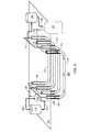
図2は、核エネルギーを使用して処理領域200を加熱するシステムの概略図を示している。システムは、ヘリウム系ガス移動機202、原子炉204、熱交換機ユニット206、および伝熱流体移動機208を含むことができる。ヘリウム系ガス移動機202は、加熱されたヘリウムを、原子炉204から熱交換機ユニット206にブロー、圧送、または押し込むことができる。熱交換機ユニット206からのヘリウムは、ヘリウム系ガス移動機202を通過して原子炉204に至ることができる。原子炉204からのヘリウムは、約900℃と約1000℃の間の温度であってもよい。ヘリウムガス移動機202からのヘリウムは、約500℃と約600℃の間の温度であってもよい。伝熱流体移動機208は、伝熱流体を熱交換機ユニット206から処理領域200中に引っ張ることができる。伝熱流体は、伝熱流体移動機208を通過して熱交換ユニット206に至ることができる。伝熱流体は、二酸化炭素、溶融塩、および/または他の流体でもよい。伝熱流体は、熱交換器ユニット206を出た後、約850℃と約950℃の間の温度であってもよい。 FIG. 2 shows a schematic diagram of a system for heating the
一部の実施形態では、システムは、補助パワーユニット210を含む。一部の実施形態では、補助パワーユニット210は、ヘリウムを熱交換機ユニット206から発生器内に通過させて電気を作り出すことによってパワーを発生させる。ヘリウムは、原子炉204に送られる前に、ヘリウムの圧力および温度を調製するために1つまたは複数の圧縮機および/または熱交換機に送られ得る。一部の実施形態では、補助パワーユニット210は、伝熱流体(たとえばアンモニアまたはアンモニア水)を用いてパワーを発生させる。熱交換機ユニット206からのヘリウムは、追加の熱交換機ユニットに送られて熱を伝熱流体に伝達することができる。伝熱流体は、電気を発生させるパワーサイクル(カリーナサイクルなど)内に取り込まれ得る。一実施形態では、原子炉204は、400MW反応炉であり、補助パワーユニット210は、約30MWの電気を発生させる。 In some embodiments, the system includes an
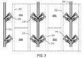
図3は、インサイチュ熱処理プロセスのための配置の概略立面図を示している。(U字形状または他の形状でもよい)坑井穴が、処理領域200A、200B、200C、200Dを画定するように地層内に形成され得る。追加の処理領域が、示された処理領域の側部に形成されてもよい。処理領域200A、200B、200C、200Dは、300m、500m、1000m、または1500mを超える幅を有することができる。坑井穴の坑井出口および入口は、坑井開口領域212内に形成され得る。レール線214が、処理領域200の側部に沿って形成され得る。倉庫、事務所、および/または消費燃料貯蔵施設は、レール線214のほぼ末端に位置することができる。施設216は、レール線214の支線に沿って間隔をおいて形成され得る。施設216は、原子炉、圧縮機、熱交換器ユニット、および/または高温の伝熱流体を坑井穴まで循環させるのに必要とされる他の装置を含むことができる。施設216は、地層から生成された地層流体を処理するための地表施設を含むこともできる。一部の実施形態では、施設216’内で生成された伝熱流体は、処理領域200Aを通過した後、施設216’’内の反応炉によって再加熱され得る。一部の実施形態では、各々の施設216は、施設に隣接する処理領域200の2分の1内の坑井に高温処理流体を与えるために使用される。施設216は、処理領域からの生成が完了した後、レールによって別の施設現場に移動され得る。 FIG. 3 shows a schematic elevation view of the arrangement for the in situ heat treatment process. Well holes (which may be U-shaped or other shapes) may be formed in the formation to define the
一部の実施形態では、核エネルギーは、地表下地層のある部分を直接的に加熱するために使用される。地表下地層の部分は、炭化水素処理領域の一部でもよい。原子炉施設を使用して伝熱流体を加熱し、その伝達流体が、次いで、地表下地層を加熱するために地表下地層に提供されることに反して、1つまたは複数の自己調節型核加熱器が、地表下地層を直接的に加熱するために地下に配置され得る。自己調節型原子炉は、1つまたは複数のトンネル内またはその近傍に配置され得る。 In some embodiments, nuclear energy is used to directly heat a portion of the ground sublayer. The portion of the ground surface underlayer may be a part of the hydrocarbon treatment region. One or more self-regulating nuclei, as opposed to heating a heat transfer fluid using a nuclear reactor facility, which transfer fluid is then provided to the surface sublayer to heat the surface sublayer A heater can be placed underground to directly heat the surface subsurface layer. Self-regulating nuclear reactors can be located in or near one or more tunnels.
一部の実施形態では、地表下地層の処理は、地層を、所望の最初の上限範囲(たとえば250℃と350℃の間)まで加熱することを必要とする。地表下地層を所望の温度範囲まで加熱した後、温度は、範囲内で、所望の時間(たとえば炭化水素のある割合が熱分解された状態になる、または地層内の平均温度が選択された値に到達するまで)維持され得る。地層温度が上昇するにつれて、加熱器温度は、ある期間にわたってゆっくりと低下し得る。これまでのところ本明細書において説明された特定の原子炉(たとえば核ペブルベッド反応炉)は、動作時、約900℃の自然の温度出力限界に到達し、最終的には、ウラン235燃料が劣化したときに減衰し、より低い温度が加熱器において経時的に生成される結果となる。特定の原子炉(たとえば核ペブルベッド反応炉)の自然のパワー出力曲線は、特定の地表下地層に対する所望の加熱対時間のプロファイルを提供するために使用され得る。 In some embodiments, the treatment of the ground foundation layer requires heating the formation to the desired initial upper range (eg, between 250 ° C. and 350 ° C.). After heating the ground surface layer to the desired temperature range, the temperature is within the range, for a desired time (for example, a proportion of hydrocarbons are pyrolyzed, or the average temperature within the formation is selected) Until it is reached). As the formation temperature increases, the heater temperature can slowly decrease over a period of time. So far, certain reactors described herein (eg, nuclear pebble bed reactors) have reached a natural temperature output limit of about 900 ° C. in operation, and ultimately uranium 235 fuel is It decays when it degrades, resulting in lower temperatures being generated over time in the heater. The natural power output curve of a particular nuclear reactor (eg, nuclear pebble bed reactor) can be used to provide a desired heating versus time profile for a particular surface sublayer.
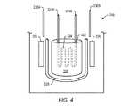
一部の実施形態では、核エネルギーは、自己調節型原子炉(たとえばペブルベッド反応炉または核分裂性金属水素化物反応炉)によって与えられる。自己調節型原子炉は、その設計に基づくある特定の温度を超えてはならない。自己調節型原子炉は、従来の原子炉に対してかなり小型のものになり得る。自己調節型原子炉は、たとえば約2平方m、3平方m、または5平方mあるいはそれより小さいサイズでもよい。自己調節型原子炉は、モジュール式でもよい。 In some embodiments, the nuclear energy is provided by a self-regulating nuclear reactor (eg, a pebble bed reactor or a fissile metal hydride reactor). A self-regulating nuclear reactor must not exceed a certain temperature based on its design. Self-regulating reactors can be much smaller than conventional reactors. The self-regulating nuclear reactor may be, for example, about 2 square meters, 3 square meters, or 5 square meters or smaller in size. The self-regulating nuclear reactor may be modular.
図4は、自己調節型原子炉型218の配置図を示している。一部の実施形態では、自己調節型原子炉は、核分裂性金属水素化物220を含む。核分裂性金属水素化物は、核反応用の燃料として、ならびに核反応用の減速体として機能することができる。原子炉の炉心は、金属水素化物材料を含むことができる。水素化物中に含有された水素同位体の温度駆動された易動性は、核反応を制御するように機能することができる。温度が、自己調節型原子炉218の炉心222内で設定点を上回って上昇する場合、水素同位体は、水素化物から解離し、炉心から逃げ、パワー生成は低下する。炉心温度が低下する場合、水素同位体は、核分裂性金属水素化物と再び結合して、プロセスを反転させる。一部の実施形態では、核分裂性金属水素化物は、水素がより容易に核分裂性金属水素化物に浸透することを可能にする粉末形態のものでもよい。 FIG. 4 shows a layout diagram of the self-regulating
その基本的設計により、自己調節型原子炉は、もしあるとすれば、核反応自体の制御に関連付けられた移動部分をわずかに含み得る。自己調節型原子炉の小型で簡単な構造は、特に、今日世界中で一般的に使用されている従来の商用原子炉に比べて注目すべき利点を有することができる。利点は、比較的容易な製造、輸送性、安定性、安全性、および財政的な実行可能性を含むことができる。自己調節型原子炉の小型設計は、反応炉を、1つの施設で構築し、炭化水素含有地層などの使用する現場に輸送することを可能にし得る。自己調節型原子炉は、到着し、取り付けた時点で、動作させることができる。 Due to its basic design, the self-regulating nuclear reactor, if any, may contain a few moving parts associated with the control of the nuclear reaction itself. The small and simple structure of self-regulating nuclear reactors can have significant advantages, especially compared to conventional commercial reactors that are commonly used around the world today. Benefits can include relatively easy manufacturing, transportability, stability, safety, and financial viability. The small design of the self-regulating nuclear reactor may allow the reactor to be built in one facility and transported to the site of use, such as a hydrocarbon-containing formation. A self-regulating nuclear reactor can be operated when it arrives and is installed.
自己調節型原子炉は、1ユニットあたり約数十メガワットの熱出力を生成することができる。2基またはそれ以上の自己調節型原子炉が、炭化水素含有地層で使用され得る。自己調節型原子炉は、約450℃と約900℃の間、約500℃と約800℃の間、約550℃と約650℃の間の範囲にある燃料温度で作動することができる。作動温度は、約550℃と約600℃の間の範囲内でもよい。作動温度は、約500℃と約650℃の間の範囲内でもよい。 Self-regulating nuclear reactors can generate about tens of megawatts of thermal power per unit. Two or more self-regulating nuclear reactors can be used in hydrocarbon-containing formations. Self-regulating nuclear reactors can operate at fuel temperatures that range between about 450 ° C. and about 900 ° C., between about 500 ° C. and about 800 ° C., and between about 550 ° C. and about 650 ° C. The operating temperature may be in a range between about 550 ° C and about 600 ° C. The operating temperature may be in a range between about 500 ° C and about 650 ° C.
自己調節型原子炉は、炉心222内にエネルギー抽出システム224を含むことができる。エネルギー抽出システム224は、エネルギーを、動作中の原子炉によって生成された熱の形態で抽出するように機能することができる。エネルギー抽出システムは、配管224Aおよび224B中を循環する伝熱流体を含むことができる。チュービングの少なくとも一部分は、原子炉の炉心内に配置され得る。流体循環システムは、伝熱流体を配管中で連続的に循環させるように機能することができる。炉心内に配置された配管の密度および体積は、核分裂性金属水素化物の濃縮度に依存し得る。一部の実施形態では、エネルギー抽出システムは、アルカリ金属の(たとえばポタシューム)ヒートパイプを含む。ヒートパイプは、さらに、機械式ポンプが伝熱流体を炉心中に運ぶ必要性を解消することによって自己調節型原子炉をより簡単にすることができる。自己調節型原子炉をいくらかでも簡易化することにより、いかなる故障の機会も減少させ、原子炉の安全性を向上させ得る。エネルギー抽出システムは、ヒートパイプに連結された熱交換機を含むことができる。伝熱流体は、熱エネルギーを熱交換機から運ぶことができる。 The self-regulating nuclear reactor can include an
原子炉の寸法は、核分裂性金属水素化物の濃縮度によって決定され得る。より高い濃縮度を有する原子炉の結果、より小さい関連する反応炉が得られる。適正な寸法は、炭化水素含有地層および地層エネルギーの必要性の個々の仕様によって最終的に決定され得る。一部の実施形態では、核分裂性金属水素化物は、親物質水素化物で希釈される。親物質水素化物は、核分裂部分の異なる同位体から形成され得る。核分裂性金属水素化物は、核分裂性水素化物U235を含むことができ、親物質水素化物は、同位体U238を含むことができる。一部の実施形態では、原子炉の炉心は、約5%のU235および約95%のU238から形成された核燃料を含むことができる。The dimensions of the reactor can be determined by the enrichment of the fissile metal hydride. A reactor with a higher enrichment results in a smaller associated reactor. The appropriate dimensions can ultimately be determined by the individual specifications of the hydrocarbon-containing formation and formation energy needs. In some embodiments, the fissile metal hydride is diluted with the parent material hydride. The parent hydride can be formed from different isotopes of the fission moiety. The fissile metal hydride can include the fissile hydride U235 and the parent material hydride can include the isotope U238 . In some embodiments, the reactor core may include nuclear fuel formed from about 5% U235 and about 95% U238 .
親物質すなわち非核分裂性の水素化物と混合された核分裂性金属水素化物の他の組合せもまた作用する。核分裂性金属水素化物は、プルトニウムを含むことができる。プルトニウムの低い溶融温度(約640℃)は、水素化物の粒子を、蒸気発生器にパワー供給するための反応炉燃料としてはそれほど魅力的にしないが、より低い反応炉温度を必要とする他の用途では有用になり得る。核分裂性金属水素化物は、トリウム水素化物を含むことができる。トリウムは、その高い溶融温度(約1775℃)により、反応炉のより高い温度での作動を可能にする。一部の実施形態では、核分裂性金属水素化物の異なる組合せが、異なるエネルギー出力パラメータを達成するために使用される。 Other combinations of fissile metal hydrides mixed with the parent material, i.e. non-fissile hydride, also work. The fissile metal hydride can include plutonium. The low melting temperature of plutonium (about 640 ° C.) makes hydride particles less attractive as a reactor fuel for powering a steam generator, but other temperatures that require lower reactor temperatures. Can be useful in applications. The fissile metal hydride can include thorium hydride. Thorium allows the reactor to operate at higher temperatures due to its high melting temperature (about 1775 ° C.). In some embodiments, different combinations of fissile metal hydrides are used to achieve different energy output parameters.
一部の実施形態では、原子炉218は、1つまたは複数の水素貯蔵容器226を含むことができる。水素貯蔵容器は、炉心から排出された水素を吸収するために、1つまたは複数の非核分裂性水素吸収材料を含むことができる。非核分裂性水素吸収材料は、炉心の水素化物の非核分裂性同位体を含むことができる。非核分裂性水素吸収材料は、核分裂性材料の解離圧力に近い水素化物の解離圧力を有することができる。 In some embodiments, the
炉心222および水素貯蔵容器226は、絶縁層228によって分離され得る。絶縁層は、炉心からの中性子の漏出を低減するために中性子反射体として機能することができる。絶縁層は、熱帰還を低減するように機能することができる。絶縁層は、水素貯蔵容器が、核炉心によって(たとえば放射加熱でまたはチャンバ内のガスからの対流加熱で)加熱されることから保護するように機能することができる。 The
炉心の効果的な定常状態温度は、周囲の水素ガス圧力によって制御され得る。周囲の水素ガス圧力は、非核分裂性水素吸収材料が維持される温度によって制御され得る。核分裂性金属水素化物の温度は、抽出されているエネルギーの量から独立し得る。エネルギー出力は、パワーを原子炉から抽出するエネルギー抽出システムの能力に依存し得る。 The effective steady state temperature of the core can be controlled by the ambient hydrogen gas pressure. The ambient hydrogen gas pressure can be controlled by the temperature at which the non-fissile hydrogen absorbing material is maintained. The temperature of the fissile metal hydride can be independent of the amount of energy being extracted. The energy output can depend on the ability of the energy extraction system to extract power from the reactor.
反応炉心内の水素ガスは、正しい量および同位体含有量を維持するために、純度に関して監視され、定期的に再加圧され得る。一部の実施形態では、水素ガスは、1本または複数本の管(たとえば管230Aおよび230B)による原子炉の炉心へのアクセスを介して維持される。自己調節型原子炉の温度は、自己調節型原子炉に供給された水素の圧力を制御することによって制御され得る。圧力は、1つまたは複数の地点における(たとえば伝熱流体が1つまたは複数の坑井穴に入る地点における)伝熱流体の温度に基づいて調節され得る。 The hydrogen gas in the reactor core can be monitored for purity and periodically repressurized to maintain the correct amount and isotope content. In some embodiments, hydrogen gas is maintained via access to the reactor core by one or more tubes (eg,
一部の実施形態では、自己調節型原子炉内で発生する核反応は、中性子吸収ガスを導入することによって制御され得る。中性子吸収ガスは、十分な量で、自己調節型原子炉内で核反応を抑えることができる(最終的には反応炉の温度を周囲温度まで低減する)。中性子吸収ガスは、キセノン135を含むことができる。In some embodiments, the nuclear reaction that occurs in the self-regulating nuclear reactor can be controlled by introducing a neutron absorbing gas. A sufficient amount of neutron-absorbing gas can suppress nuclear reactions in the self-regulating reactor (eventually reducing the reactor temperature to ambient temperature). The neutron absorbing gas can include xenon135 .
一部の実施形態では、動作中の自己調節型原子炉の核反応は、制御棒を用いて制御される。制御棒は、自己調節型原子炉の核炉心の少なくとも一部分内に少なくとも部分的に配置され得る。制御棒は、1つまたは複数の中性子吸収材料から形成され得る。中性子吸収材料は、それだけに限定されないが、銀、インジウム、カドミウム、ボロン、コバルト、ハフニウム、ジスプロシウム、ガドリニウム、サマリウム、エルビウム、およびユーロピウムを含むことができる。 In some embodiments, the nuclear reaction of the operating self-regulating nuclear reactor is controlled using control rods. The control rod may be at least partially disposed within at least a portion of the self-regulating nuclear core. The control rod may be formed from one or more neutron absorbing materials. Neutron absorbing materials can include, but are not limited to, silver, indium, cadmium, boron, cobalt, hafnium, dysprosium, gadolinium, samarium, erbium, and europium.
現在、本明細書において説明された自己調節型原子炉は、動作時、約900℃の自然の温度出力限界に到達し、最終的には、燃料が劣化したときに減衰する。自己調節型原子炉の自然のパワー出力曲線は、特定の地表下地層に対する所望の加熱対時間のプロファイルを提供するために使用され得る。 Currently, the self-regulating nuclear reactor described herein reaches a natural temperature output limit of about 900 ° C. in operation and eventually decays when the fuel degrades. The natural power output curve of a self-regulating nuclear reactor can be used to provide a desired heating versus time profile for a particular surface layer.
一部の実施形態では、自己調節型原子炉は、約1/E(Eは、時にオイラー数と称され、約2.71828に等しい)の速度で減衰する自然エネルギー出力を有することができる。一部の実施形態では、自己調節型原子炉は、約4年から約8年の期間で、1/Eの初期パワーに減衰する自然のパワー出力を有することができる。通常、地層が所望の温度まで加熱されると、熱はそれほど必要とされず、地層を加熱するために地層内に投入される熱エネルギーの量は、経時的に低減される。一部の実施形態では、地層の少なくとも一部分への経時的な熱入力は、自己調節型原子炉からのパワーの減衰速度と近似的に相関する。少なくとも一部の自己調節型原子炉は自然減衰するため、加熱システムは、原子炉からのパワーの減衰の自然速度を利用するように設計され得る。 In some embodiments, the self-regulating nuclear reactor may have a natural energy output that decays at a rate of about 1 / E (E is sometimes referred to as Euler number and is equal to about 2.71828). In some embodiments, the self-regulating nuclear reactor may have a natural power output that decays to an initial power of 1 / E over a period of about 4 years to about 8 years. Usually, when a formation is heated to a desired temperature, less heat is needed and the amount of thermal energy input into the formation to heat the formation is reduced over time. In some embodiments, the heat input over time to at least a portion of the formation is approximately correlated with the rate of decay of power from the self-regulating nuclear reactor. Because at least some self-regulating nuclear reactors decay naturally, the heating system can be designed to take advantage of the natural rate of decay of power from the reactor.
加熱システムは、通常、2つまたはそれ以上の加熱器を含む。加熱器は、通常、地層中に配置された坑井穴内に配置される。坑井穴は、たとえば、U字形状およびL字形状の坑井穴、または他の形状の坑井穴を含むことができる。一部の実施形態では、坑井穴間の間隔は、自己調節型原子炉のパワー出力の減衰速度に基づいて決定される。 A heating system typically includes two or more heaters. The heater is typically placed in a wellbore located in the formation. Well holes can include, for example, U-shaped and L-shaped well holes, or other shaped well holes. In some embodiments, the spacing between the well holes is determined based on the decay rate of the power output of the self-regulating reactor.
自己調節型原子炉は、最初、坑井穴の少なくとも一部分に、約300ワット/フィートのパワー出力を与えることができ、その後、所定の期間にわたって約120ワット/フィートに低下する。所定の期間は、自己調節型原子炉自体の設計(たとえば核炉心内で使用される燃料ならびに燃料の濃縮度)によって決定され得る。パワー出力における自然低下は、地層のパワー注入対時間依存に合致することができる。いずれの変数(たとえばパワー出力および/またはパワー注入)も、2つの変数が、少なくとも近似的に相関するまたは合致するように調整され得る。自己調節型原子炉は、4から9年、5から7年、または約7年の期間にわたって減衰するように設計され得る。自己調節型原子炉の減衰期間は、IUP(インサイチュ品質向上プロセス)および/またはICP(インサイチュ転化プロセス)加熱サイクルに対応することができる。 The self-regulating nuclear reactor can initially provide at least a portion of the wellbore with a power output of about 300 watts / ft and then drop to about 120 watts / ft over a predetermined period of time. The predetermined period may be determined by the design of the self-regulating reactor itself (eg, the fuel used in the nuclear core as well as the enrichment of the fuel). The natural drop in power output can be matched to the formation's power injection versus time dependence. Any variable (eg, power output and / or power injection) can be adjusted so that the two variables are at least approximately correlated or matched. Self-regulating nuclear reactors can be designed to decay over a period of 4 to 9 years, 5 to 7 years, or about 7 years. The decay period of the self-regulating reactor may correspond to an IUP (In Situ Quality Improvement Process) and / or ICP (In Situ Conversion Process) heating cycle.
一部の実施形態では、加熱器の坑井穴間の間隔は、パワーを提供するために使用される1基または複数基の原子炉の減衰速度によって決まる。一部の実施形態では、加熱器の坑井穴間の間隔は、約8メートルと約11メートルの間、約9メートルと約10メートルの間、または約9.4メートルと約9.8メートルの間の範囲である。 In some embodiments, the spacing between the well bores of the heater is determined by the decay rate of the reactor or reactors used to provide power. In some embodiments, the spacing between the well bores of the heater is between about 8 meters and about 11 meters, between about 9 meters and about 10 meters, or between about 9.4 meters and about 9.8 meters. The range between.
特定の状況では、自己調節型原子炉の特定のレベルのパワー出力を、核炉心内の燃料材料の自然減衰が通常可能である期間より長く継続することが有利になり得る。一部の実施形態では、出力レベルを所望の範囲内に保つために、第2の自己調節型原子炉が、処理されている(たとえば加熱されている)地層に連結され得る。第2の自己調節型原子炉は、一部の実施形態では、減衰されたパワー出力を有する。第2の反応炉のパワー出力は、使用前にすでに低下している可能性がある。2基の自己調節型原子炉のパワー出力は、第1の自己調節型原子炉の初期のパワー出力および/または所望のパワー出力にほぼ等しいものになり得る。追加の自己調節型原子炉が、所望のパワー出力を達成するために必要に応じて地層に連結され得る。そのようなシステムは、有利には、自己調節型原子炉の有効的な有用寿命を増大させることができる。 In certain situations, it may be advantageous to continue a specific level of power output of the self-regulating reactor for longer than the period during which natural decay of the fuel material in the nuclear core is normally possible. In some embodiments, a second self-regulating nuclear reactor can be coupled to the formation being treated (eg, heated) to keep the power level within a desired range. The second self-regulating nuclear reactor has a attenuated power output in some embodiments. The power output of the second reactor may have already dropped before use. The power output of the two self-regulating reactors can be approximately equal to the initial power output of the first self-regulating reactor and / or the desired power output. Additional self-regulating nuclear reactors can be coupled to the formation as needed to achieve the desired power output. Such a system can advantageously increase the useful useful life of a self-regulating nuclear reactor.
自己調節型原子炉の有効的な有用寿命は、原子炉によって生成された熱エネルギーを用いて蒸気を生成することによって延ばされてもよく、これにより、使用される地層および/またはシステムによっては、本明細書において概説された他の使用よりもかなり少ない熱エネルギーしか必要とされないことがある。蒸気は、それだけに限定されないが、電気の生成、現場での水素の生成、炭化水素の転化および/または炭化水素の品質向上を含む、いくつかの目的のために使用されてもよい。炭化水素は、生成された蒸気を地層内に注入することによって、インサイチュで転化されてもよく、かつ/または易動化されてもよい。 The useful useful life of a self-regulating nuclear reactor may be extended by generating steam using the thermal energy generated by the reactor, depending on the formation and / or system used. Much less heat energy may be required than the other uses outlined herein. Steam may be used for a number of purposes including, but not limited to, electricity generation, in situ hydrogen generation, hydrocarbon conversion and / or hydrocarbon quality improvement. The hydrocarbons may be converted in situ and / or mobilized by injecting the generated steam into the formation.
生成物の流れ(たとえばメタン、炭化水素、および/または重炭化水素を含む流れ)が、原子炉によって加熱された伝熱流体で加熱された地層から生成され得る。原子炉または第2の原子炉によって発生した熱から生成された蒸気が、生成物の流れの少なくとも一部分を改質するために使用され得る。生成物の流れは、少なくともいくらかの分子状水素を作り出すように改質され得る。 A product stream (eg, a stream comprising methane, hydrocarbons, and / or heavy hydrocarbons) can be generated from a formation heated with a heat transfer fluid heated by a nuclear reactor. Steam generated from heat generated by the reactor or the second reactor may be used to reform at least a portion of the product stream. The product stream can be modified to produce at least some molecular hydrogen.
分子状水素は、生成物の流れの少なくとも一部分の品質向上のために使用され得る。分子状水素は、地層内に注入され得る。生成物の流れは、地表の品質向上プロセスから生成され得る。生成物の流れは、インサイチュ熱処理プロセスから生成され得る。生成物の流れは、地表下の蒸気加熱プロセスから生成され得る。 Molecular hydrogen can be used to improve the quality of at least a portion of the product stream. Molecular hydrogen can be injected into the formation. The product stream can be generated from a surface quality improvement process. The product stream can be generated from an in situ heat treatment process. The product stream can be generated from a subsurface steam heating process.
蒸気の少なくとも一部分は、地表下の蒸気加熱プロセス内に注入され得る。蒸気の少なくともいくらかが、メタンを改質するために使用され得る。蒸気の少なくとも一部分は、電気発生のために使用され得る。地層内の炭化水素の少なくとも一部分は、蒸気および/または蒸気からの熱によって易動化され得る。 At least a portion of the steam can be injected into the subsurface steam heating process. At least some of the steam can be used to reform methane. At least a portion of the steam can be used for electricity generation. At least a portion of the hydrocarbons in the formation can be mobilized by steam and / or heat from the steam.
一部の実施形態では、自己調節型原子炉は、(たとえば蒸気駆動タービンを介して)電気を生成するために使用され得る。電気は、通常電気に関連付けられたいくつもの用途で使用されてもよい。具体的には、電気は、エネルギーを必要とするインサイチュ熱処理プロセスに関連付けられた用途に使用され得る。 In some embodiments, a self-regulating nuclear reactor can be used to generate electricity (eg, via a steam-driven turbine). Electricity may be used in any number of applications normally associated with electricity. Specifically, electricity can be used in applications associated with in situ heat treatment processes that require energy.
自己調節型原子炉からの電気は、ダウンホール電気加熱器用のエネルギーを与えるために使用され得る。電気は、処理領域の周りに低温の障壁(凍結障壁)を形成するために、および/またはインサイチュ熱処理プロセス現場においてまたはその近くに位置する処理施設に電気を与えるために、流体を冷却するために使用され得る。一部の実施形態では、原子炉によって生成された電気は、伝熱流体を処理領域中で循環させるために使用されるコンジットを抵抗式に加熱するために使用される。一部の実施形態では、原子力は、インサイチュ熱処理プロセスに必要とされる圧縮機および/またはポンプを作動させる電気を発生させるために使用される(圧縮機/ポンプは、圧縮されたガス(酸化流体および/または複数の酸化剤集合体への燃料など)を、処理領域に与える)。インサイチュ熱処理プロセスのかなりのコストは、従来の電気エネルギー源が、インサイチュ熱処理プロセスの圧縮機および/またはポンプにパワー供給するために使用される場合、圧縮機および/またはポンプをインサイチュ熱処理プロセスの寿命にわたって作動させるものになり得る。 Electricity from the self-regulating reactor can be used to provide energy for the downhole electric heater. Electricity to cool fluids to form a cold barrier (freeze barrier) around the processing region and / or to provide electricity to a processing facility located at or near the in situ heat treatment process site Can be used. In some embodiments, the electricity generated by the nuclear reactor is used to resistively heat the conduit that is used to circulate the heat transfer fluid in the processing region. In some embodiments, nuclear power is used to generate electricity that operates the compressors and / or pumps required for the in situ heat treatment process (the compressor / pump is a compressed gas (oxidizing fluid And / or fuel to a plurality of oxidant aggregates). The considerable cost of the in situ heat treatment process is that if a conventional electrical energy source is used to power the compressor and / or pump of the in situ heat treatment process, the compressor and / or pump will span the life of the in situ heat treatment process. Can be actuated.
自己調節型原子炉からの熱を電気に転化することが、原子炉によって生成された熱エネルギーの最も効率的な使用でないことがある。一部の実施形態では、自己調節型原子炉によって生成された熱エネルギーは、地層の一部分を直接加熱するために使用される。一部の実施形態では、1基または複数基の自己調節型原子炉は、生成された熱エネルギーが、地層の少なくとも一部分を直接的に加熱するように地下の地層内地下に配置される。1基または複数基の自己調節型原子炉は、地層内地下のオーバーバーデンの下方に配置されてもよく、したがって、自己調節型原子炉によって生成された熱エネルギーの効率的な使用を向上させる。地下に配置された自己調節型原子炉は、さらなる保護のためにある材料内に閉じ込められ得る。たとえば、地下に配置された自己調節型原子炉は、コンクリート容器内に閉じ込められてもよい。 Converting heat from self-regulating reactors into electricity may not be the most efficient use of thermal energy generated by the reactor. In some embodiments, the thermal energy generated by the self-regulating reactor is used to directly heat a portion of the formation. In some embodiments, the one or more self-regulating nuclear reactors are located underground in the underground formation such that the generated thermal energy directly heats at least a portion of the formation. One or more self-regulating reactors may be located below the overburden in the formation underground, thus improving the efficient use of the thermal energy generated by the self-regulating reactor. Self-regulating nuclear reactors located underground can be confined within certain materials for further protection. For example, a self-regulating nuclear reactor located underground may be confined within a concrete vessel.
一部の実施形態では、自己調節型原子炉によって生成された熱エネルギーは、伝熱流体を使用して抽出され得る。自己調節型原子炉によって生成された熱エネルギーは、伝熱流体を用いて地層の少なくとも一部分に伝達され、その中で分配され得る。伝熱流体は、自己調節型原子炉のエネルギー抽出システムの配管中を循環することができる。伝熱流体が自己調節型原子炉内の炉心内で、およびその中を循環するとき、核反応から生成された熱は、伝熱流体を加熱する。 In some embodiments, the thermal energy generated by the self-regulating nuclear reactor can be extracted using a heat transfer fluid. Thermal energy generated by the self-regulating nuclear reactor can be transferred to and distributed in at least a portion of the formation using a heat transfer fluid. The heat transfer fluid can circulate in the piping of the energy extraction system of the self-regulating nuclear reactor. As the heat transfer fluid circulates in and through the core in the self-regulating reactor, the heat generated from the nuclear reaction heats the heat transfer fluid.
一部の実施形態では、2つまたはそれ以上の伝熱流体が、自己調節型原子炉によって生成された熱エネルギーを伝達するために使用され得る。第1の伝熱流体は、自己調節型原子炉のエネルギー抽出システムの配管中を循環することができる。第1の伝熱流体は、熱交換機を通過することができ、第2の伝熱流体を加熱するために使用され得る。第2の伝熱流体は、炭化水素流体をインサイチュで処理する、電気分解ユニットにパワー供給する、および/または他の目的のために使用され得る。第1の伝熱流体および第2の伝熱流体は、異なる材料でもよい。2つの伝熱流体を使用することにより、システムおよび作業員が第1の伝熱流体によって吸収されたあらゆる放射線に不必要にさらされるリスクを低減することができる。核放射の吸収に対して抵抗性を有する伝熱流体が、使用され得る(たとえば亜硝酸塩または硝酸塩)。 In some embodiments, two or more heat transfer fluids can be used to transfer the thermal energy generated by the self-regulating nuclear reactor. The first heat transfer fluid can circulate in the piping of the energy extraction system of the self-regulating nuclear reactor. The first heat transfer fluid can pass through the heat exchanger and can be used to heat the second heat transfer fluid. The second heat transfer fluid may be used for treating the hydrocarbon fluid in situ, powering the electrolysis unit, and / or other purposes. The first heat transfer fluid and the second heat transfer fluid may be different materials. By using two heat transfer fluids, the risk of unnecessarily exposing the system and personnel to any radiation absorbed by the first heat transfer fluid can be reduced. A heat transfer fluid that is resistant to absorption of nuclear radiation can be used (eg, nitrite or nitrate).
一部の実施形態では、エネルギー抽出システムは、アルカリ金属の(たとえばポタシューム)ヒートパイプを含む。ヒートパイプは、さらに、機械式ポンプが伝熱流体を炉心まで運ぶ必要性を解消することによって自己調節型原子炉を簡単にすることができる。自己調節型原子炉をいくらかでも簡易化することにより、故障の機会を減少させ、原子炉の安全性を向上させ得る。エネルギー抽出システムは、ヒートパイプに連結された熱交換機を含むことができる。伝熱流体は、熱エネルギーを熱交換機から運ぶことができる。 In some embodiments, the energy extraction system includes an alkali metal (eg, potassium) heat pipe. The heat pipe can further simplify the self-regulating nuclear reactor by eliminating the need for a mechanical pump to carry the heat transfer fluid to the core. Any simplification of the self-regulating reactor can reduce the chance of failure and improve the safety of the reactor. The energy extraction system can include a heat exchanger coupled to the heat pipe. The heat transfer fluid can carry thermal energy from the heat exchanger.
伝熱流体は、天然油または合成油、溶融金属、溶融塩、または他のタイプの高温伝熱流体を含むことができる。伝熱流体は、通常の作動状態において低い粘性および高い熱容量を有することができる。伝熱流体が溶融塩、または地層内で凝固する可能性を有する他の流体であるとき、システムの配管は、必要な場合に配管を抵抗的に加熱するために電気源に電気的に連結されてもよく、かつ/または1つもしくは複数の加熱器が、伝熱流体を液体状態に維持するために配管内にまたはそれに隣接して配置されてもよい。一部の実施形態では、絶縁導電体加熱器が、配管内に置かれる。絶縁導電体は、配管内で固体を溶融することができる。 The heat transfer fluid can include natural or synthetic oils, molten metals, molten salts, or other types of high temperature heat transfer fluids. The heat transfer fluid can have a low viscosity and a high heat capacity in normal operating conditions. When the heat transfer fluid is a molten salt or other fluid that has the potential to solidify in the formation, the piping of the system is electrically connected to an electrical source to resistively heat the piping when necessary. And / or one or more heaters may be placed in or adjacent to the piping to maintain the heat transfer fluid in a liquid state. In some embodiments, an insulated conductor heater is placed in the piping. The insulated conductor can melt the solid in the pipe.
図5は、自己調節型原子炉218を用いた、U字形状の坑井穴234を有する地層232内に配置されたインサイチュ熱処理システムの実施形態の配置図を示している。図5に示す自己調節型原子炉218は、約70MWの熱を生成することができる。一部の実施形態では、坑井穴234間の間隔は、自己調節型原子炉218のエネルギー出力の減衰速度に基づいて決定される。 FIG. 5 shows a layout diagram of an embodiment of an in-situ heat treatment system disposed in a
U字形状の坑井穴は、オーバーバーデン236中を下り、炭化水素含有層238に入ることができる。オーバーバーデン236に隣接する坑井穴234内の配管は、絶縁部分240を含むことができる。絶縁された貯蔵タンク242は、溶融塩を地層232から配管244を通じて受け入れることができる。配管244は、約350℃から約500℃の範囲にある温度を有する溶融塩を輸送することができる。貯蔵タンク内の温度は、使用される溶融塩のタイプに依存し得る。貯蔵タンク内の温度は、約350℃近くでもよい。ポンプは、溶融塩を、配管246を通して自己調節型原子炉218まで移動させることができる。ポンプの各々は、たとえば、6kg/秒から12kg/秒の溶融塩を移動させることが必要である。各々の自己調節型原子炉218は、溶融塩に熱を与えることができる。溶融塩は、配管248から坑井穴234まで進むことができる。層238を通過する坑井穴234の加熱された部分は、一部の実施形態では、約8000フィート(約2400m)から約10,000フィート(約3000m)まで延びることができる。自己調節型原子炉218からの溶融塩の出口温度は、約550℃でもよい。各々の自己調節型原子炉218は、溶融塩を、地層に入る約20個またはそれ以上の坑井穴234に供給することができる。溶融塩は、地層を流れ抜けて、配管244を通って貯蔵タンク242に戻る。 A U-shaped wellbore can descend through the
一部の実施形態では、核エネルギーは、熱電併給プロセスにおいて使用される。炭化水素含有地層(たとえばタールサンド地層)から炭化水素を生成するための実施形態では、生成された炭化水素は、重炭化水素を有する1つまたは複数の部分を含むことができる。炭化水素は、2つ以上のプロセスを用いて地層から生成され得る。特定の実施形態では、核エネルギーは、炭化水素の少なくとも一部を生成するのを支援するために使用される。生成された重炭化水素の少なくとも一部は、熱分解温度にかけられ得る。重炭化水素の熱分解は、蒸気を生成するために使用され得る。蒸気は、それだけに限定されないが、電気の生成、炭化水素の転化、および/または炭化水素の品質向上などを含む、いくつかの目的のために使用されてもよい。 In some embodiments, nuclear energy is used in a combined heat and power process. In embodiments for generating hydrocarbons from hydrocarbon-containing formations (eg, tar sand formations), the generated hydrocarbons can include one or more portions with heavy hydrocarbons. Hydrocarbons can be generated from the formation using two or more processes. In certain embodiments, nuclear energy is used to help generate at least a portion of the hydrocarbons. At least a portion of the produced heavy hydrocarbons can be subjected to a pyrolysis temperature. The pyrolysis of heavy hydrocarbons can be used to produce steam. Steam may be used for a number of purposes, including but not limited to electricity generation, hydrocarbon conversion, and / or hydrocarbon quality improvement.
一部の実施形態では、伝熱流体は、自己調節型原子炉を用いて加熱される。伝熱流体は、蒸気生成を可能にする温度(たとえば約550℃から約600℃)まで加熱され得る。一部の実施形態では、インサイチュ熱処理プロセスガスおよび/または燃料は、改質ユニットまで進む。一部の実施形態では、インサイチュ熱処理プロセスガスは、燃料と混合され、改質ユニットに渡される。インサイチュ熱処理プロセスガスの一部分は、ガス分離ユニットに入ることができる。ガス分離ユニットは、燃料および1つまたは複数の流れ(たとえば二酸化炭素または硫化水素)を生成するために、インサイチュ熱処理プロセスガスから1つまたは複数の成分を取り出すことができる。燃料は、それだけに限定されないが、水素、最大で5個の炭素数を有する炭化水素、またはそれらの混合物を含むことができる。 In some embodiments, the heat transfer fluid is heated using a self-regulating nuclear reactor. The heat transfer fluid may be heated to a temperature that allows steam generation (eg, from about 550 ° C. to about 600 ° C.). In some embodiments, the in situ heat treatment process gas and / or fuel proceeds to the reforming unit. In some embodiments, the in situ heat treatment process gas is mixed with fuel and passed to the reforming unit. A portion of the in-situ heat treatment process gas can enter the gas separation unit. The gas separation unit can remove one or more components from the in situ heat treatment process gas to produce fuel and one or more streams (eg, carbon dioxide or hydrogen sulfide). The fuel can include, but is not limited to, hydrogen, hydrocarbons having up to 5 carbons, or mixtures thereof.
改質装置ユニットは、蒸気改質装置でもよい。改質装置ユニットは、蒸気を燃料(たとえばメタン)と合成させて水素を生成することができる。たとえば、改質ユニットは、水性ガスシフト触媒を含むことができる。改質装置ユニットは、水素を他の成分から分離することができる1つまたは複数の分離システム(たとえば膜および/または圧力スイング吸収システム)を含むことができる。燃料および/またはインサイチュ熱処理プロセスガスの改質は、水素の流れおよび酸化炭素の流れを生成することができる。 The reformer unit may be a steam reformer. The reformer unit can generate hydrogen by synthesizing steam with fuel (eg, methane). For example, the reforming unit can include a water gas shift catalyst. The reformer unit can include one or more separation systems (eg, membranes and / or pressure swing absorption systems) that can separate hydrogen from other components. The reforming of the fuel and / or in situ heat treatment process gas can produce a hydrogen stream and a carbon oxide stream.
燃料および/またはインサイチュ熱処理プロセスガスの改質は、水素を生成するための炭化水素の触媒改質および/または熱改質に関して当技術分野で知られている技術を用いて実施され得る。一部の実施形態では、蒸気から水素を生成するために、電解が使用される。水素の流れの一部分またはすべては、それだけに限定されないが、インサイチュに関してはエネルギー源および/または水素源、またはインサイチュ以外での炭化水素の水素化などの他の目的のために使用され得る。 The reforming of the fuel and / or in situ heat treatment process gas may be performed using techniques known in the art for catalytic reforming and / or thermal reforming of hydrocarbons to produce hydrogen. In some embodiments, electrolysis is used to generate hydrogen from steam. Some or all of the hydrogen stream can be used for other purposes such as, but not limited to, in-situ, energy and / or hydrogen source, or hydrogenation of hydrocarbons other than in-situ.
自己調節型原子炉は、炭化水素含有地層に隣接して位置する施設において水素を生成するために使用され得る。炭化水素含有地層の現場で水素を生成する能力は、水素が、炭化水素含有地層における現場での炭化水素の転化および品質向上のために使用される複数の方法により、極めて有利である。 Self-regulating nuclear reactors can be used to produce hydrogen in facilities located adjacent to hydrocarbon-containing formations. The ability to generate hydrogen in situ in hydrocarbon-containing formations is highly advantageous due to the multiple methods in which hydrogen is used for in-situ hydrocarbon conversion and quality improvement in hydrocarbon-containing formations.
一部の実施形態では、第1の伝熱流体は、地層内に貯蔵された熱エネルギーを用いて加熱される。熱エネルギーは、いくつかの異なる熱処理方法の後、地層内で得ることができる。 In some embodiments, the first heat transfer fluid is heated using thermal energy stored in the formation. Thermal energy can be obtained in the formation after several different heat treatment methods.
自己調節型原子炉は、多くの現在の一定出力原子炉に対して複数の利点を有する。しかしながら、複数の新規の原子炉が存在しており、その設計は、構築に対する法的認証を受けている。核エネルギーは、いくつかの異なるタイプの利用可能な原子炉および現在開発中(たとえばIV世代反応炉)の原子炉によって与えられ得る。 Self-regulating reactors have several advantages over many current constant power reactors. However, there are a number of new nuclear reactors whose designs are legally certified for construction. Nuclear energy can be provided by several different types of available reactors and reactors currently under development (eg, IV generation reactors).
一部の実施形態では、原子炉は、非常に高温の反応炉(VHTR)を含む。VHTRは、炭化水素流体をインサイチュで処理するために、電解ユニットにパワー供給するために、および/または他の目的のために、たとえばヘリウムを冷却剤として使用してガスタービンを駆動させることができる。VHTRは、約950℃までまたはそれ以上の熱を生成することができる。一部の実施形態では、原子炉は、ナトリウム冷却高速炉(SFR)を含む。SFRは、より小さい規模で(たとえば50MWe)設計されてもよく、したがって炭化水素流体をインサイチュで処理するために、電解ユニットにパワー供給するために、および/または他の目的のために、現場で製造するためのよりコスト効果の高いものになり得る。SFRは、モジュール式設計のものでもよく、潜在的に運搬可能なものでもよい。SFRは、約500℃と約600℃の間、約525℃と約575℃の間、または540℃と約560℃の間の範囲にある温度を生成することができる。 In some embodiments, the nuclear reactor includes a very high temperature reactor (VHTR). The VHTR can drive a gas turbine using, for example, helium as a coolant, to process hydrocarbon fluids in situ, to power an electrolysis unit, and / or for other purposes, for example. . The VHTR can generate heat up to about 950 ° C. or higher. In some embodiments, the nuclear reactor includes a sodium cooled fast reactor (SFR). SFRs may be designed on a smaller scale (eg, 50 MWe) and thus in-situ to process hydrocarbon fluids in situ, to power electrolysis units, and / or for other purposes. It can be more cost effective to manufacture. The SFR may be of modular design or potentially transportable. The SFR can produce a temperature in the range between about 500 ° C and about 600 ° C, between about 525 ° C and about 575 ° C, or between 540 ° C and about 560 ° C.
一部の実施形態では、ペブルベッド反応炉が、熱エネルギーを与えるために使用される。ペブルベッド反応炉は、165MWeまで生成することができる。ペブルベッド反応炉は、約500℃と約1100℃の間、約800℃と約1000℃の間、または約900℃と約950℃の間の範囲にある温度を生成することができる。一部の実施形態では、原子炉は、従来の軽水炉(LWR)および超臨界圧化石燃料ボイラーに少なくとも部分的に基づく超臨界圧軽水冷却炉(SCWR)を含む。SCWRは、約400℃と約650℃の間、約450℃と約550℃の間、または約500℃と約550℃の間の範囲にある温度を生成することができる。 In some embodiments, a pebble bed reactor is used to provide thermal energy. Pebble bed reactors can produce up to 165 MWe. The pebble bed reactor can produce a temperature in the range between about 500 ° C and about 1100 ° C, between about 800 ° C and about 1000 ° C, or between about 900 ° C and about 950 ° C. In some embodiments, the nuclear reactor includes a conventional light water reactor (LWR) and a supercritical light water cooled reactor (SCWR) based at least in part on a supercritical pressure fossil fuel boiler. The SCWR can produce a temperature in the range between about 400 ° C and about 650 ° C, between about 450 ° C and about 550 ° C, or between about 500 ° C and about 550 ° C.
一部の実施形態では、原子炉は、鉛冷却高速炉(LFR)を含む。LFRは、モジュラー式システムから数百メガワットまたはそれ以上のサイズの範囲内で製造され得る。LFRは、約400℃と約900℃の間、約500℃と約850℃の間、または約550℃と約800℃の間の範囲にある温度を生成することができる。 In some embodiments, the nuclear reactor includes a lead cooled fast reactor (LFR). The LFR can be manufactured in a size range of several hundred megawatts or more from a modular system. The LFR can produce a temperature in the range between about 400 ° C and about 900 ° C, between about 500 ° C and about 850 ° C, or between about 550 ° C and about 800 ° C.
一部の実施形態では、原子炉は、溶融塩炉(MSR)を含む。MSRは、約1400℃の沸点を有するフッ化溶融塩中に溶解された、核分裂性同位体、親物質同位体、および核分裂同位体を含む。フッ化溶融塩は、反応炉燃料および冷却材の両方として機能することができる。MSRは、約400℃と約900℃の間、約500℃と約850℃の間、または約600℃と約800℃の間の範囲にある温度を生成することができる。 In some embodiments, the nuclear reactor includes a molten salt reactor (MSR). MSR includes fissionable isotopes, parent material isotopes, and fission isotopes dissolved in a fluorinated molten salt having a boiling point of about 1400 ° C. The fluorinated molten salt can function as both reactor fuel and coolant. The MSR can produce a temperature in the range between about 400 ° C and about 900 ° C, between about 500 ° C and about 850 ° C, or between about 600 ° C and about 800 ° C.
一部の実施形態では、2つまたはそれ以上の伝熱流体(たとえば溶融塩)が、熱エネルギーを、炭化水素含有地層におよび/またはそこから伝達するために使用される。第1の伝熱流体が、(たとえば原子炉を用いて)加熱され得る。第1の伝熱流体は、地層の少なくとも一部分を加熱するために、地層のその部分内の複数の坑井穴中で循環されてもよい。第1の伝熱流体は、第1の伝熱流体が液体の形態であり、安定した第1の温度範囲を有することができる。第1の伝熱流体は、その部分が、所望の温度範囲(たとえば第1の温度範囲の上限に向かう温度)に到達するまで、地層の部分中で循環されてもよい。 In some embodiments, two or more heat transfer fluids (eg, molten salts) are used to transfer thermal energy to and / or from hydrocarbon-containing formations. The first heat transfer fluid may be heated (eg, using a nuclear reactor). The first heat transfer fluid may be circulated in a plurality of well holes in that portion of the formation to heat at least a portion of the formation. The first heat transfer fluid may have a stable first temperature range, with the first heat transfer fluid being in liquid form. The first heat transfer fluid may be circulated in the portion of the formation until the portion reaches a desired temperature range (eg, temperature toward the upper limit of the first temperature range).
第2の伝熱流体が、(たとえば原子炉を用いて)加熱され得る。第2の伝熱流体は、第2の伝熱流体が液体の形態であり、安定した第2の温度範囲を有することができる。第2の温度範囲の上限は、より高温であり、第1の温度範囲を上回り得る。第2の温度範囲の下限は、第1の温度範囲と重なり得る。第2の伝熱流体は、地層の一部を、第1の伝熱流体で可能である温度よりも高い温度まで加熱するために、地層のその部分内の複数の坑井穴中で循環されてもよい。 The second heat transfer fluid may be heated (eg, using a nuclear reactor). The second heat transfer fluid may have a stable second temperature range in which the second heat transfer fluid is in liquid form. The upper limit of the second temperature range is higher and can exceed the first temperature range. The lower limit of the second temperature range may overlap with the first temperature range. The second heat transfer fluid is circulated in a plurality of well holes in that portion of the formation to heat a portion of the formation to a temperature higher than that possible with the first heat transfer fluid. May be.
2つまたはそれ以上の異なる伝熱流体を使用する利点は、たとえば地層の一部を、他の補助的加熱方法(たとえば電気加熱器)をできるだけ用いずに全体効率を増大させながら、通常可能である温度よりもはるかに高い温度まで加熱する能力を含むことができる。2つまたはそれ以上の異なる伝熱流体を用いることは、地層の一部分を所望の温度まで加熱できる温度範囲を有する伝熱流体が、利用可能でない場合に必要になり得る。 The advantage of using two or more different heat transfer fluids is usually possible, for example, while part of the formation increases the overall efficiency with as little as possible using other auxiliary heating methods (eg electric heaters). The ability to heat to a temperature much higher than a certain temperature can be included. The use of two or more different heat transfer fluids may be necessary when a heat transfer fluid having a temperature range that can heat a portion of the formation to a desired temperature is not available.
一部の実施形態では、炭化水素含有地層の一部分が所望の温度範囲まで加熱された後、第1の伝熱流体が、地層のその部分中で再循環されてもよい。第1の伝熱流体は、(溶融塩の場合、必要な場合に伝熱流体を溶融点まで加熱する以外は)地層中の再循環の前に加熱され得ない。第1の伝熱流体は、地層の以前のインサイチュ熱処理から地層の一部分内にすでに貯蔵されている熱エネルギーを用いて加熱され得る。第1の伝熱流体は、次いで、地層から外に伝達されてもよく、それにより、第1の伝熱流体によって回収された熱エネルギーが、地層のその部分内、地層の第2の部分内、および/または追加の地層内で何らかの他のプロセスに再利用され得る。 In some embodiments, after a portion of the hydrocarbon-containing formation is heated to a desired temperature range, the first heat transfer fluid may be recycled in that portion of the formation. The first heat transfer fluid cannot be heated prior to recirculation in the formation (other than heating the heat transfer fluid to the melting point if necessary in the case of molten salt). The first heat transfer fluid may be heated using thermal energy already stored in a portion of the formation from a previous in situ heat treatment of the formation. The first heat transfer fluid may then be transferred out of the formation such that the thermal energy recovered by the first heat transfer fluid is within that portion of the formation, within the second portion of the formation. And / or can be reused for some other process within additional formations.
実施例
非限定的な例が、以下で説明される。Examples Non-limiting examples are described below.
パワー必要量シミュレーション
溶融塩で地層を加熱するためのパワー必要量を決定するためのシミュレーションが実施された。溶融塩が、炭化水素含有地層内の坑井穴中で循環され、溶融塩を用いて地層を加熱するためのパワー必要量が、経時的に評価された。パワー必要量に対する効果を決定するために、坑井穴間の距離が変更された。Power requirement simulation A simulation was conducted to determine the power requirement for heating the formation with molten salt. Molten salt was circulated in the wellbore within the hydrocarbon-containing formation, and the power requirements for heating the formation with the molten salt were evaluated over time. To determine the effect on power requirements, the distance between wells was changed.
図6は、インサイチュ熱処理のパワー注入必要量のパワー(W/ft)(y軸)対時間(年)(x軸)の曲線250を示している。図7は、坑井穴間の異なる間隔に対する、インサイチュ熱処理のパワー注入必要量のパワー(W/ft)(y軸)対時間(日)(x軸)を示している。曲線252から260は、図7で結果を示している。曲線252は、約14.4メートルの間隔を有する加熱器の坑井穴に対する、必要とされるパワー対時間を示している。曲線254は、約13.2メートルの間隔を有する加熱器の坑井穴に対する、必要とされるパワー対時間を示している。曲線256は、加熱器の坑井穴が六角形パターンに広げられ、約12メートルの間隔を有する状態の、Alberta、Canadaのグロスモント地層に対する、必要とされるパワー対時間を示している。曲線258は、約9.6メートルの間隔を有する加熱器の坑井穴に対する、必要とされるパワー対時間を示している。曲線260は、約7.2メートルの間隔を有する加熱器の坑井穴に対する、必要とされるパワー対時間を示している。 FIG. 6 shows a
図7のグラフから、曲線258によって表された坑井穴の間隔は、特定の原子炉(たとえば約4年間から約9年間で約1/Eまで減衰するパワー出力を有する少なくとも一部の原子炉など)の経時的なパワー出力と近似的に相関する間隔である。図7の曲線252から256は、約12メートルから約14.4メートルの範囲にある間隔を有する加熱器の坑井穴に対して必要とされるパワー出力を示している。約12メートルを上回る加熱器の坑井穴間の間隔は、特定の原子炉が与え得るよりも多いエネルギー入力を必要とすることがある。約8メートル未満の加熱器の坑井穴間の間隔(たとえば、図7において曲線260)は、特定の原子炉によって与えられたエネルギー入力を効率的に利用しないことがある。 From the graph of FIG. 7, the wellbore spacing represented by
図8は、坑井穴間の異なる間隔に対するインサイチュ熱処理の貯留器平均温度(℃)(y軸)対時間(日)(x軸)を示している。曲線252から260は、坑井の間隔に対するパワー入力必要量に基づく地層内の経時的な温度上昇を示している。炭化水素含有地層のインサイチュ熱処理の目標温度は、一部の実施形態では、たとえば約350℃でもよい。地層に対する目標温度は、少なくとも地層のタイプおよび/または所望の炭化水素生成物に応じて変化し得る。図8内の曲線252から260に対する坑井穴間の間隔は、図7における曲線252から260に対するものと同じである。図8内の曲線252から256は、約12メートルから約14.4メートルの範囲にある間隔を有する加熱器の坑井穴に対する地層内の経時的な温度の上昇を示している。約12メートルを上回る加熱器の坑井穴間の間隔は、地層を過渡にゆっくりと加熱することがあり、それにより、特定の原子炉が与えることができるエネルギーよりも多くのエネルギーが必要とされ得る(特に現行の例では約5年後)。約8メートル未満の加熱器の坑井穴間の間隔は(たとえば図8の曲線260によって表されるように)、一部のインサイチュ熱処理状況においては地層を過渡に速く加熱することがある。図8内のグラフから、曲線258によって表された坑井穴の間隔は、約350℃の一般的な目標温度を所望の時間枠(たとえば約5年)で達成する間隔になり得る。 FIG. 8 shows the reservoir average temperature (° C.) (y-axis) versus time (day) (x-axis) for in-situ heat treatment for different intervals between well holes.
本発明のさまざまな態様のさらなる改変形態および代替の実施形態が、この説明の観点から当業者に明確になり得る。したがって、この説明は、例示的のみとして解釈されるものとし、当業者に本発明を実施する一般的な方法を教示する目的のためのものである。本明細書において図示され説明された本発明の形態は、現在好ましい実施形態としてみなされることが理解されるものとする。要素および材料は、本明細書において例示され説明されたものに対して代用されてもよく、部分およびプロセスは逆転させてもよく、本発明の特定の特徴は独立的に利用されてもよく、これらすべては、本発明のこの説明の利益を有した後、当業者に明確になるはずである。以下の特許請求の範囲で説明する本発明の趣旨および範囲から逸脱することなく、本明細書において説明された要素に変更が加えられてもよい。さらに、本明細書において独立的に説明された特徴は、特定の実施態様において組み合わせられてもよいことが理解されるものとする。 Further modifications and alternative embodiments of the various aspects of the invention may become apparent to those skilled in the art in view of this description. Accordingly, this description is to be construed as illustrative only and is for the purpose of teaching those skilled in the art the general manner of carrying out the invention. It is to be understood that the forms of the invention shown and described herein are considered as presently preferred embodiments. Elements and materials may be substituted for those illustrated and described herein, parts and processes may be reversed, and certain features of the invention may be utilized independently, All of this should be clear to the skilled person after having the benefit of this description of the invention. Changes may be made in the elements described herein without departing from the spirit and scope of the invention as described in the following claims. Furthermore, it is to be understood that features described independently herein may be combined in certain embodiments.
Claims (19)
Translated fromJapanese坑井穴の少なくとも2つ内に配置された少なくとも1つの加熱器と、
地層の温度を地層からの炭化水素の生成を可能にする温度まで上昇させるために、エネルギーを加熱器の少なくとも1つに与えるように構成された自己調節型原子炉とを備える、炭化水素を地表下地層から生成するためのインサイチュ熱処理システムであって、
地層の少なくとも一部分への経時的な熱入力が、自己調節型原子炉からのパワーの減衰速度と少なくとも近似的に相関する、システム。Multiple well holes in the formation;
At least one heater disposed in at least two of the well holes;
A self-regulating nuclear reactor configured to provide energy to at least one of the heaters to raise the temperature of the formation to a temperature that enables the production of hydrocarbons from the formation; An in situ heat treatment system for generating from an underlayer,
A system wherein heat input over time to at least a portion of the formation correlates at least approximately with the rate of decay of power from the self-regulating reactor.
Applications Claiming Priority (5)
| Application Number | Priority Date | Filing Date | Title |
|---|---|---|---|
| US10497408P | 2008-10-13 | 2008-10-13 | |
| US61/104,974 | 2008-10-13 | ||
| US16849809P | 2009-04-10 | 2009-04-10 | |
| US61/168,498 | 2009-04-10 | ||
| PCT/US2009/060093WO2010045099A1 (en) | 2008-10-13 | 2009-10-09 | Using self-regulating nuclear reactors in treating a subsurface formation |
Publications (1)
| Publication Number | Publication Date |
|---|---|
| JP2012508838Atrue JP2012508838A (en) | 2012-04-12 |
Family
ID=42097829
Family Applications (6)
| Application Number | Title | Priority Date | Filing Date |
|---|---|---|---|
| JP2011531190AExpired - Fee RelatedJP5611962B2 (en) | 2008-10-13 | 2009-10-09 | Circulating heat transfer fluid system used to treat ground surface underlayer |
| JP2011531195AExpired - Fee RelatedJP5611963B2 (en) | 2008-10-13 | 2009-10-09 | System and method for treating a ground underlayer with a conductor |
| JP2011531193ACeasedJP2012509417A (en) | 2008-10-13 | 2009-10-09 | Use of self-regulating nuclear reactors in the treatment of surface subsurface layers. |
| JP2011531194APendingJP2012509418A (en) | 2008-10-13 | 2009-10-09 | System and method for forming subsurface well holes |
| JP2011531191ACeasedJP2012508838A (en) | 2008-10-13 | 2009-10-09 | Use of self-regulating nuclear reactors in the treatment of surface subsurface layers. |
| JP2011531189AExpired - Fee RelatedJP5611961B2 (en) | 2008-10-13 | 2009-10-09 | Heating of a circulating heat transfer fluid in a subsurface hydrocarbon formation. |
Family Applications Before (4)
| Application Number | Title | Priority Date | Filing Date |
|---|---|---|---|
| JP2011531190AExpired - Fee RelatedJP5611962B2 (en) | 2008-10-13 | 2009-10-09 | Circulating heat transfer fluid system used to treat ground surface underlayer |
| JP2011531195AExpired - Fee RelatedJP5611963B2 (en) | 2008-10-13 | 2009-10-09 | System and method for treating a ground underlayer with a conductor |
| JP2011531193ACeasedJP2012509417A (en) | 2008-10-13 | 2009-10-09 | Use of self-regulating nuclear reactors in the treatment of surface subsurface layers. |
| JP2011531194APendingJP2012509418A (en) | 2008-10-13 | 2009-10-09 | System and method for forming subsurface well holes |
Family Applications After (1)
| Application Number | Title | Priority Date | Filing Date |
|---|---|---|---|
| JP2011531189AExpired - Fee RelatedJP5611961B2 (en) | 2008-10-13 | 2009-10-09 | Heating of a circulating heat transfer fluid in a subsurface hydrocarbon formation. |
Country Status (10)
| Country | Link |
|---|---|
| US (14) | US8256512B2 (en) |
| EP (6) | EP2361343A1 (en) |
| JP (6) | JP5611962B2 (en) |
| CN (5) | CN102187054B (en) |
| AU (6) | AU2009303608B2 (en) |
| BR (2) | BRPI0919775A2 (en) |
| CA (6) | CA2739086A1 (en) |
| IL (5) | IL211950A (en) |
| RU (6) | RU2518649C2 (en) |
| WO (7) | WO2010045099A1 (en) |
Families Citing this family (250)
| Publication number | Priority date | Publication date | Assignee | Title |
|---|---|---|---|---|
| AU5836701A (en) | 2000-04-24 | 2001-11-07 | Shell Int Research | In situ recovery of hydrocarbons from a kerogen-containing formation |
| US6929067B2 (en) | 2001-04-24 | 2005-08-16 | Shell Oil Company | Heat sources with conductive material for in situ thermal processing of an oil shale formation |
| AU2002360301B2 (en) | 2001-10-24 | 2007-11-29 | Shell Internationale Research Maatschappij B.V. | In situ thermal processing and upgrading of produced hydrocarbons |
| US8161998B2 (en) | 2007-06-04 | 2012-04-24 | Matos Jeffrey A | Frozen/chilled fluid for pipelines and for storage facilities |
| WO2004097159A2 (en) | 2003-04-24 | 2004-11-11 | Shell Internationale Research Maatschappij B.V. | Thermal processes for subsurface formations |
| ATE392534T1 (en) | 2004-04-23 | 2008-05-15 | Shell Int Research | PREVENTION OF RETURN IN A HEATED COUNTER OF AN IN-SITU CONVERSION SYSTEM |
| US10047280B2 (en) | 2013-09-20 | 2018-08-14 | Baker Hughes, A Ge Company, Llc | Organophosphorus containing composites for use in well treatment operations |
| US7987613B2 (en)* | 2004-10-12 | 2011-08-02 | Great River Energy | Control system for particulate material drying apparatus and process |
| US7500528B2 (en) | 2005-04-22 | 2009-03-10 | Shell Oil Company | Low temperature barrier wellbores formed using water flushing |
| EP2010755A4 (en) | 2006-04-21 | 2016-02-24 | Shell Int Research | HEATING SEQUENCE OF MULTIPLE LAYERS IN A FORMATION CONTAINING HYDROCARBONS |
| US8159825B1 (en) | 2006-08-25 | 2012-04-17 | Hypres Inc. | Method for fabrication of electrical contacts to superconducting circuits |
| US20080083566A1 (en)* | 2006-10-04 | 2008-04-10 | George Alexander Burnett | Reclamation of components of wellbore cuttings material |
| GB2461362A (en) | 2006-10-20 | 2010-01-06 | Shell Int Research | Systems and processes for use in treating subsurface formations |
| EP2115368A1 (en)* | 2007-02-02 | 2009-11-11 | Steve D. Shivvers | High efficiency drier with multi stage heating and drying zones |
| CN101688442B (en) | 2007-04-20 | 2014-07-09 | 国际壳牌研究有限公司 | Molten salt as a heat transfer fluid for heating a subsurface formation |
| JP5063195B2 (en)* | 2007-05-31 | 2012-10-31 | ラピスセミコンダクタ株式会社 | Data processing device |
| RU2496067C2 (en) | 2007-10-19 | 2013-10-20 | Шелл Интернэшнл Рисерч Маатсхаппий Б.В. | Cryogenic treatment of gas |
| US8318131B2 (en) | 2008-01-07 | 2012-11-27 | Mcalister Technologies, Llc | Chemical processes and reactors for efficiently producing hydrogen fuels and structural materials, and associated systems and methods |
| US9188086B2 (en) | 2008-01-07 | 2015-11-17 | Mcalister Technologies, Llc | Coupled thermochemical reactors and engines, and associated systems and methods |
| AT10660U1 (en)* | 2008-03-19 | 2009-07-15 | Binder Co Ag | DRYER WITH COOLING MEDIUM |
| US20090260823A1 (en) | 2008-04-18 | 2009-10-22 | Robert George Prince-Wright | Mines and tunnels for use in treating subsurface hydrocarbon containing formations |
| US8430168B2 (en)* | 2008-05-21 | 2013-04-30 | Valkyrie Commissioning Services, Inc. | Apparatus and methods for subsea control system testing |
| EP2361343A1 (en) | 2008-10-13 | 2011-08-31 | Shell Oil Company | Using self-regulating nuclear reactors in treating a subsurface formation |
| US8441361B2 (en) | 2010-02-13 | 2013-05-14 | Mcallister Technologies, Llc | Methods and apparatuses for detection of properties of fluid conveyance systems |
| US20110203776A1 (en)* | 2009-02-17 | 2011-08-25 | Mcalister Technologies, Llc | Thermal transfer device and associated systems and methods |
| WO2010118315A1 (en) | 2009-04-10 | 2010-10-14 | Shell Oil Company | Treatment methodologies for subsurface hydrocarbon containing formations |
| US7792250B1 (en)* | 2009-04-30 | 2010-09-07 | Halliburton Energy Services Inc. | Method of selecting a wellbore cement having desirable characteristics |
| GB2474249B (en)* | 2009-10-07 | 2015-11-04 | Mark Collins | An apparatus for generating heat |
| US8356935B2 (en) | 2009-10-09 | 2013-01-22 | Shell Oil Company | Methods for assessing a temperature in a subsurface formation |
| CA2776521C (en)* | 2009-10-09 | 2018-01-02 | Shell Internationale Research Maatschappij B.V. | Methods for assessing a temperature in a subsurface formation |
| US8257112B2 (en) | 2009-10-09 | 2012-09-04 | Shell Oil Company | Press-fit coupling joint for joining insulated conductors |
| US9466896B2 (en) | 2009-10-09 | 2016-10-11 | Shell Oil Company | Parallelogram coupling joint for coupling insulated conductors |
| US9310245B2 (en)* | 2009-10-28 | 2016-04-12 | Csir | Integrated sensing device for assessing integrity of a rock mass and corresponding method |
| US8386221B2 (en)* | 2009-12-07 | 2013-02-26 | Nuovo Pignone S.P.A. | Method for subsea equipment subject to hydrogen induced stress cracking |
| US8602658B2 (en)* | 2010-02-05 | 2013-12-10 | Baker Hughes Incorporated | Spoolable signal conduction and connection line and method |
| AU2011216244A1 (en) | 2010-02-13 | 2012-09-06 | Mcalister Technologies, Llc | Reactor vessels with transmissive surfaces for producing hydrogen-based fuels and structural elements, and associated systems and methods |
| JP5726912B2 (en)* | 2010-02-13 | 2015-06-03 | マクアリスター テクノロジーズ エルエルシー | Chemical reactor with re-radiating surface and related systems and methods |
| US8397828B2 (en)* | 2010-03-25 | 2013-03-19 | Baker Hughes Incorporated | Spoolable downhole control system and method |
| US8967259B2 (en) | 2010-04-09 | 2015-03-03 | Shell Oil Company | Helical winding of insulated conductor heaters for installation |
| US8939207B2 (en) | 2010-04-09 | 2015-01-27 | Shell Oil Company | Insulated conductor heaters with semiconductor layers |
| US8631866B2 (en) | 2010-04-09 | 2014-01-21 | Shell Oil Company | Leak detection in circulated fluid systems for heating subsurface formations |
| US9033042B2 (en) | 2010-04-09 | 2015-05-19 | Shell Oil Company | Forming bitumen barriers in subsurface hydrocarbon formations |
| US8701768B2 (en) | 2010-04-09 | 2014-04-22 | Shell Oil Company | Methods for treating hydrocarbon formations |
| US8820406B2 (en) | 2010-04-09 | 2014-09-02 | Shell Oil Company | Electrodes for electrical current flow heating of subsurface formations with conductive material in wellbore |
| US20110277992A1 (en)* | 2010-05-14 | 2011-11-17 | Paul Grimes | Systems and methods for enhanced recovery of hydrocarbonaceous fluids |
| CN110220254A (en) | 2010-05-25 | 2019-09-10 | 7Ac技术公司 | The method and system of air conditioning and other processing is carried out using liquid drier |
| US8943686B2 (en) | 2010-10-08 | 2015-02-03 | Shell Oil Company | Compaction of electrical insulation for joining insulated conductors |
| US8586866B2 (en) | 2010-10-08 | 2013-11-19 | Shell Oil Company | Hydroformed splice for insulated conductors |
| US8857051B2 (en) | 2010-10-08 | 2014-10-14 | Shell Oil Company | System and method for coupling lead-in conductor to insulated conductor |
| WO2012048191A1 (en)* | 2010-10-08 | 2012-04-12 | Shell Oil Company | Methods for joining insulated conductors |
| CA2811795A1 (en)* | 2010-10-08 | 2012-04-12 | Renfeng Richard Cao | Methods of heating a subsurface formation using electrically conductive particles |
| WO2012091816A2 (en)* | 2010-12-28 | 2012-07-05 | Hansen Energy Services Llc | Liquid lift pumps for gas wells |
| US9139316B2 (en) | 2010-12-29 | 2015-09-22 | Cardinal Health 414, Llc | Closed vial fill system for aseptic dispensing |
| US20120228286A1 (en)* | 2011-03-09 | 2012-09-13 | Central Garden And Pet Company | Inductive Heating Device for Aquarium Tanks |
| JP5399436B2 (en)* | 2011-03-30 | 2014-01-29 | 公益財団法人地球環境産業技術研究機構 | Storage substance storage device and storage method |
| AU2012254060B2 (en)* | 2011-04-08 | 2015-07-09 | Shell Internationale Research Maatschappij B.V. | Compaction of electrical insulation for joining insulated conductors |
| CA2832295C (en) | 2011-04-08 | 2019-05-21 | Shell Internationale Research Maatschappij B.V. | Systems for joining insulated conductors |
| US9016370B2 (en) | 2011-04-08 | 2015-04-28 | Shell Oil Company | Partial solution mining of hydrocarbon containing layers prior to in situ heat treatment |
| US8978769B2 (en)* | 2011-05-12 | 2015-03-17 | Richard John Moore | Offshore hydrocarbon cooling system |
| CN102200004A (en)* | 2011-05-12 | 2011-09-28 | 刘锋 | Special energy-saving matching device for beam pumping unit and pumping unit thereof |
| US8887806B2 (en) | 2011-05-26 | 2014-11-18 | Halliburton Energy Services, Inc. | Method for quantifying cement blend components |
| US9417332B2 (en) | 2011-07-15 | 2016-08-16 | Cardinal Health 414, Llc | Radiopharmaceutical CZT sensor and apparatus |
| US20130102772A1 (en) | 2011-07-15 | 2013-04-25 | Cardinal Health 414, Llc | Systems, methods and devices for producing, manufacturing and control of radiopharmaceuticals-full |
| US20130020727A1 (en) | 2011-07-15 | 2013-01-24 | Cardinal Health 414, Llc. | Modular cassette synthesis unit |
| US9102529B2 (en) | 2011-07-25 | 2015-08-11 | H2 Catalyst, Llc | Methods and systems for producing hydrogen |
| EP2742207A4 (en) | 2011-08-12 | 2016-06-29 | Mcalister Technologies Llc | Systems and methods for extracting and processing gases from submerged sources |
| WO2013025640A2 (en)* | 2011-08-12 | 2013-02-21 | Mcalister Technologies, Llc | Geothermal energization of a non-combustion chemical reactor and associated systems and methods |
| US8734546B2 (en) | 2011-08-12 | 2014-05-27 | Mcalister Technologies, Llc | Geothermal energization of a non-combustion chemical reactor and associated systems and methods |
| US8826657B2 (en) | 2011-08-12 | 2014-09-09 | Mcallister Technologies, Llc | Systems and methods for providing supplemental aqueous thermal energy |
| WO2013025659A1 (en) | 2011-08-12 | 2013-02-21 | Mcalister Technologies, Llc | Reducing and/or harvesting drag energy from transport vehicles, includings for chemical reactors, and associated systems and methods |
| US8911703B2 (en) | 2011-08-12 | 2014-12-16 | Mcalister Technologies, Llc | Reducing and/or harvesting drag energy from transport vehicles, including for chemical reactors, and associated systems and methods |
| WO2013025655A2 (en) | 2011-08-12 | 2013-02-21 | Mcalister Technologies, Llc | Systems and methods for providing supplemental aqueous thermal energy |
| US9302681B2 (en) | 2011-08-12 | 2016-04-05 | Mcalister Technologies, Llc | Mobile transport platforms for producing hydrogen and structural materials, and associated systems and methods |
| US8888408B2 (en) | 2011-08-12 | 2014-11-18 | Mcalister Technologies, Llc | Systems and methods for collecting and processing permafrost gases, and for cooling permafrost |
| WO2013025647A2 (en) | 2011-08-12 | 2013-02-21 | Mcalister Technologies, Llc | Fuel-cell systems operable in multiple modes for variable processing of feedstock materials and associated devices, systems, and methods |
| US8669014B2 (en) | 2011-08-12 | 2014-03-11 | Mcalister Technologies, Llc | Fuel-cell systems operable in multiple modes for variable processing of feedstock materials and associated devices, systems, and methods |
| JO3139B1 (en) | 2011-10-07 | 2017-09-20 | Shell Int Research | Forming insulated conductors using a final reduction step after heat treating |
| JO3141B1 (en) | 2011-10-07 | 2017-09-20 | Shell Int Research | Integral splice for insulated conductors |
| CA2850741A1 (en) | 2011-10-07 | 2013-04-11 | Manuel Alberto GONZALEZ | Thermal expansion accommodation for circulated fluid systems used to heat subsurface formations |
| CN104011327B (en) | 2011-10-07 | 2016-12-14 | 国际壳牌研究有限公司 | Using the dielectric properties of insulated wires in subterranean formations to determine the performance of insulated wires |
| US9243482B2 (en) | 2011-11-01 | 2016-01-26 | Nem Energy B.V. | Steam supply for enhanced oil recovery |
| EP2776664A4 (en) | 2011-11-07 | 2016-10-05 | Oklahoma Safety Equipment Company Inc | Pressure relief device, system, and method |
| CN102436856A (en)* | 2011-12-13 | 2012-05-02 | 匡仲平 | Method for avoiding nuclear radiation pollution caused by nuclear leakage accident |
| RU2485300C1 (en)* | 2011-12-14 | 2013-06-20 | Открытое акционерное общество "Татнефть" имени В.Д. Шашина | Development method of oil deposit in fractured reservoirs |
| EP2610570B1 (en)* | 2011-12-29 | 2016-11-23 | Ipsen, Inc. | Heating element arrangement for a vacuum heat treating furnace |
| EP2612983B1 (en)* | 2012-01-03 | 2014-05-21 | Quantum Technologie GmbH | Apparatus and method for oil sand exploitation |
| US10047594B2 (en) | 2012-01-23 | 2018-08-14 | Genie Ip B.V. | Heater pattern for in situ thermal processing of a subsurface hydrocarbon containing formation |
| AU2012367826A1 (en) | 2012-01-23 | 2014-08-28 | Genie Ip B.V. | Heater pattern for in situ thermal processing of a subsurface hydrocarbon containing formation |
| CN104302870B (en)* | 2012-02-18 | 2018-04-20 | 吉尼Ip公司 | For heating the method and system of hydrocarbonaceous sill |
| CA2811666C (en) | 2012-04-05 | 2021-06-29 | Shell Internationale Research Maatschappij B.V. | Compaction of electrical insulation for joining insulated conductors |
| US9303487B2 (en) | 2012-04-30 | 2016-04-05 | Baker Hughes Incorporated | Heat treatment for removal of bauschinger effect or to accelerate cement curing |
| AU2012379048B2 (en)* | 2012-05-04 | 2015-09-10 | Landmark Graphics Corporation | Systems and methods for optimal spacing of horizontal wells |
| US10210961B2 (en)* | 2012-05-11 | 2019-02-19 | Ge-Hitachi Nuclear Energy Americas, Llc | System and method for a commercial spent nuclear fuel repository turning heat and gamma radiation into value |
| US9181497B2 (en)* | 2012-05-16 | 2015-11-10 | Chevon U.S.A. Inc. | Process, method, and system for removing mercury from fluids |
| US9447675B2 (en)* | 2012-05-16 | 2016-09-20 | Chevron U.S.A. Inc. | In-situ method and system for removing heavy metals from produced fluids |
| JP2013249605A (en)* | 2012-05-31 | 2013-12-12 | Ihi Corp | Gas-hydrate collecting system |
| CN104508417B (en) | 2012-06-11 | 2017-03-29 | 7Ac技术公司 | For the method and system of the corrosion resistant heat exchanger of turbulence type |
| US10076001B2 (en)* | 2012-07-05 | 2018-09-11 | Nvent Services Gmbh | Mineral insulated cable having reduced sheath temperature |
| US8424784B1 (en) | 2012-07-27 | 2013-04-23 | MBJ Water Partners | Fracture water treatment method and system |
| US9896918B2 (en) | 2012-07-27 | 2018-02-20 | Mbl Water Partners, Llc | Use of ionized water in hydraulic fracturing |
| JP6255020B2 (en)* | 2012-08-13 | 2017-12-27 | シェブロン ユー.エス.エー. インコーポレイテッド | Improved production of clathrate by using thermosyphon |
| EP3348783B1 (en)* | 2012-09-20 | 2020-07-15 | nVent Services GmbH | Downhole wellbore heating system |
| WO2014058777A1 (en) | 2012-10-09 | 2014-04-17 | Shell Oil Company | Method for heating a subterranean formation penetrated by a wellbore |
| CA2899141A1 (en)* | 2012-10-16 | 2014-04-24 | Genie Ip B.V. | System and method for thermally treating a subsurface formation by a heated molten salt mixture |
| US10443315B2 (en)* | 2012-11-28 | 2019-10-15 | Nextstream Wired Pipe, Llc | Transmission line for wired pipe |
| WO2014089164A1 (en) | 2012-12-04 | 2014-06-12 | 7Ac Technologies, Inc. | Methods and systems for cooling buildings with large heat loads using desiccant chillers |
| RU2549654C2 (en)* | 2012-12-04 | 2015-04-27 | Общество с ограниченной ответственностью "Краснодарский Компрессорный Завод" | Nitrogen compressor plant to increase bed production rate (versions) |
| WO2014086594A1 (en) | 2012-12-06 | 2014-06-12 | Siemens Aktiengesellschaft | Arrangement and method for introducing heat into a geological formation by means of electromagnetic induction |
| GB201223055D0 (en)* | 2012-12-20 | 2013-02-06 | Carragher Paul | Method and apparatus for use in well abandonment |
| US9631848B2 (en) | 2013-03-01 | 2017-04-25 | 7Ac Technologies, Inc. | Desiccant air conditioning systems with conditioner and regenerator heat transfer fluid loops |
| US20140251596A1 (en)* | 2013-03-05 | 2014-09-11 | Cenovus Energy Inc. | Single vertical or inclined well thermal recovery process |
| US20140251608A1 (en)* | 2013-03-05 | 2014-09-11 | Cenovus Energy Inc. | Single vertical or inclined well thermal recovery process |
| KR102099693B1 (en) | 2013-03-14 | 2020-05-15 | 7에이씨 테크놀로지스, 아이엔씨. | Methods and systems for mini-split liquid desiccant air conditioning |
| WO2014160301A1 (en) | 2013-03-14 | 2014-10-02 | Mcalister Technologies, Llc | Method and apparatus for generating hydrogen from metal |
| CN105121966B (en) | 2013-03-14 | 2018-06-01 | 7Ac技术公司 | For the method and system of liquid drier air handling system transformation |
| CA2847980C (en) | 2013-04-04 | 2021-03-30 | Christopher Kelvin Harris | Temperature assessment using dielectric properties of an insulated conductor heater with selected electrical insulation |
| DE102013104643B3 (en)* | 2013-05-06 | 2014-06-18 | Borgwarner Beru Systems Gmbh | Corona ignition device, has housing tube providing support layer and conductive layer, where support layer is made of material with higher electrical conductivity than material of support layer |
| WO2014189491A1 (en)* | 2013-05-21 | 2014-11-27 | Halliburton Energy Serviices, Inc. | High-voltage drilling methods and systems using hybrid drillstring conveyance |
| EP3008396B1 (en) | 2013-06-12 | 2019-10-23 | 7AC Technologies, Inc. | Liquid desiccant air conditioning system |
| US9382785B2 (en) | 2013-06-17 | 2016-07-05 | Baker Hughes Incorporated | Shaped memory devices and method for using same in wellbores |
| CN105555908B (en) | 2013-09-20 | 2019-10-08 | 贝克休斯公司 | Use the method for surface modification of metals inorganic agent processing subsurface formations |
| RU2670802C9 (en) | 2013-09-20 | 2018-11-26 | Бейкер Хьюз Инкорпорейтед | Composites for use in stimulation of oil production and sand control operations |
| CA2920687C (en) | 2013-09-20 | 2018-08-21 | Baker Hughes Incorporated | Method of using surface modifying treatment agents to treat subterranean formations |
| NZ751779A (en) | 2013-09-20 | 2020-08-28 | Baker Hughes Inc | Method of inhibiting fouling on a metallic surface using a surface modifying treatment agent |
| US9701892B2 (en) | 2014-04-17 | 2017-07-11 | Baker Hughes Incorporated | Method of pumping aqueous fluid containing surface modifying treatment agent into a well |
| DE102013018210A1 (en)* | 2013-10-30 | 2015-04-30 | Linde Aktiengesellschaft | Method for producing a coherent ice body in a ground icing |
| GB2538392B (en)* | 2013-12-30 | 2020-08-19 | Halliburton Energy Services Inc | Ranging using current profiling |
| CA2877367C (en)* | 2014-01-13 | 2020-12-22 | Conocophillips Company | Anti-retention agent in steam-solvent oil recovery |
| US20160312598A1 (en)* | 2014-01-24 | 2016-10-27 | Halliburton Energy Services, Inc. | Method and Criteria for Trajectory Control |
| WO2015176172A1 (en) | 2014-02-18 | 2015-11-26 | Athabasca Oil Corporation | Cable-based well heater |
| US20170211849A1 (en)* | 2014-03-07 | 2017-07-27 | Greenfire Energy Inc | Process and method of producing geothermal power |
| US9637996B2 (en) | 2014-03-18 | 2017-05-02 | Baker Hughes Incorporated | Downhole uses of nanospring filled elastomers |
| KR102391093B1 (en) | 2014-03-20 | 2022-04-27 | 에머슨 클리메이트 테크놀로지즈 인코퍼레이티드 | Rooftop liquid desiccant systems and methods |
| US9618435B2 (en)* | 2014-03-31 | 2017-04-11 | Dmar Engineering, Inc. | Umbilical bend-testing |
| CA2942717C (en) | 2014-04-04 | 2022-06-21 | Dhruv Arora | Insulated conductors formed using a final reduction step after heat treating |
| US10078154B2 (en) | 2014-06-19 | 2018-09-18 | Evolution Engineering Inc. | Downhole system with integrated backup sensors |
| GB2527847A (en)* | 2014-07-04 | 2016-01-06 | Compactgtl Ltd | Catalytic reactors |
| RU2559250C1 (en)* | 2014-08-01 | 2015-08-10 | Олег Васильевич Коломийченко | Bottomhole catalytic assembly for thermal impact on formations containing hydrocarbons and solid organic substances |
| US9451792B1 (en)* | 2014-09-05 | 2016-09-27 | Atmos Nation, LLC | Systems and methods for vaporizing assembly |
| US9939421B2 (en)* | 2014-09-10 | 2018-04-10 | Saudi Arabian Oil Company | Evaluating effectiveness of ceramic materials for hydrocarbons recovery |
| JP2017533058A (en) | 2014-09-17 | 2017-11-09 | ギャリソン デンタル ソリューションズ,リミティド ライアビリティ カンパニー | Dental curing light |
| RU2569375C1 (en)* | 2014-10-21 | 2015-11-27 | Николай Борисович Болотин | Method and device for heating producing oil-bearing formation |
| DE102014223621A1 (en)* | 2014-11-19 | 2016-05-19 | Siemens Aktiengesellschaft | deposit Heating |
| CN107110525B (en) | 2014-11-21 | 2020-02-11 | 7Ac技术公司 | Method and system for micro-fluidic desiccant air conditioning |
| AR103391A1 (en) | 2015-01-13 | 2017-05-03 | Bp Corp North America Inc | METHODS AND SYSTEMS TO PRODUCE HYDROCARBONS FROM ROCA HYDROCARBON PRODUCER THROUGH THE COMBINED TREATMENT OF THE ROCK AND INJECTION OF BACK WATER |
| RU2591860C1 (en)* | 2015-02-05 | 2016-07-20 | Федеральное государственное бюджетное образовательное учреждение высшего профессионального образования "Южно-Уральский государственный университет" (национальный исследовательский университет) (ФГБОУ ВПО "ЮУрГУ" (НИУ)) | Method of extracting heavy oil from production reservoir and device for its implementation |
| FR3032564B1 (en)* | 2015-02-11 | 2017-03-03 | Saipem Sa | METHOD FOR CONNECTING CABLES WITH A UNIT DRIVING SECTION FOR VERTICALLY ASSEMBLING AN UNDERWATER FLUID TRANSPORT DRIVE |
| AU2016244116B2 (en) | 2015-04-03 | 2021-05-20 | Rama Rau YELUNDUR | Apparatus and method of focused in-situ electrical heating of hydrocarbon bearing formations |
| EP3298379A1 (en)* | 2015-05-20 | 2018-03-28 | Saudi Arabian Oil Company | Sampling techniques to detect hydrocarbon seepage |
| GB2539045A (en)* | 2015-06-05 | 2016-12-07 | Statoil Asa | Subsurface heater configuration for in situ hydrocarbon production |
| WO2017040753A1 (en)* | 2015-09-01 | 2017-03-09 | Exotex, Inc. | Construction products and systems for providing geothermal heat |
| US9556719B1 (en) | 2015-09-10 | 2017-01-31 | Don P. Griffin | Methods for recovering hydrocarbons from shale using thermally-induced microfractures |
| CA3003887C (en) | 2015-11-06 | 2024-06-25 | Oklahoma Safety Equipment Company, Inc. | Rupture disc device and method of assembly thereof |
| US10304591B1 (en)* | 2015-11-18 | 2019-05-28 | Real Power Licensing Corp. | Reel cooling method |
| WO2017100195A1 (en)* | 2015-12-09 | 2017-06-15 | Truva Inc. | Environment-aware cross-layer communication protocol in underground oil reservoirs |
| CN106917616B (en)* | 2015-12-28 | 2019-11-08 | 中国石油天然气股份有限公司 | Preheating device and method for heavy oil reservoir |
| GB2547672B (en)* | 2016-02-25 | 2018-02-21 | Rejuvetech Ltd | System and method |
| US10067201B2 (en)* | 2016-04-14 | 2018-09-04 | Texas Instruments Incorporated | Wiring layout to reduce magnetic field |
| WO2017189397A1 (en) | 2016-04-26 | 2017-11-02 | Shell Oil Company | Roller injector for deploying insulated conductor heaters |
| GB2550849B (en)* | 2016-05-23 | 2020-06-17 | Equinor Energy As | Interface and integration method for external control of the drilling control system |
| US10125588B2 (en) | 2016-06-30 | 2018-11-13 | Must Holding Llc | Systems and methods for recovering bitumen from subterranean formations |
| NO343262B1 (en)* | 2016-07-22 | 2019-01-14 | Norges Miljoe Og Biovitenskapelige Univ Nmbu | Solar thermal collecting and storage |
| CN106168119B (en)* | 2016-08-15 | 2018-07-13 | 中国石油天然气股份有限公司 | Tubular column structure of underground electric heating horizontal production well |
| CN106292277B (en)* | 2016-08-15 | 2020-01-07 | 上海交通大学 | Coordinated control method of subcritical thermal power unit based on global sliding mode control |
| WO2018067713A1 (en) | 2016-10-06 | 2018-04-12 | Shell Oil Company | Subsurface electrical connections for high voltage, low current mineral insulated cable heaters |
| WO2018067715A1 (en) | 2016-10-06 | 2018-04-12 | Shell Oil Company | High voltage, low current mineral insulated cable heater |
| CN106595113A (en)* | 2016-12-12 | 2017-04-26 | 吉林省联冠石油科技有限公司 | Heat exchange device and method for superconductive heating |
| EP3337290B1 (en)* | 2016-12-13 | 2019-11-27 | Nexans | Subsea direct electric heating system |
| WO2018144313A2 (en) | 2017-01-31 | 2018-08-09 | Saudi Arabian Oil Company | In-situ hic growth monitoring probe |
| US10041163B1 (en) | 2017-02-03 | 2018-08-07 | Ge-Hitachi Nuclear Energy Americas Llc | Plasma spray coating for sealing a defect area in a workpiece |
| US20180292133A1 (en)* | 2017-04-05 | 2018-10-11 | Rex Materials Group | Heat treating furnace |
| EP3389088A1 (en)* | 2017-04-12 | 2018-10-17 | ABB Schweiz AG | Heat exchanging arrangement and subsea electronic system |
| CN107387180B (en)* | 2017-07-17 | 2019-08-20 | 浙江陆特能源科技股份有限公司 | The method of stratum coal slurrying heating system and stratum coal slurrying power generation and heat supply on the spot on the spot |
| US10724341B2 (en) | 2017-08-14 | 2020-07-28 | Schlumberger Technology Corporation | Electrical power transmission for well construction apparatus |
| US10745975B2 (en) | 2017-08-14 | 2020-08-18 | Schlumberger Technology Corporation | Electrical power transmission for well construction apparatus |
| US10760348B2 (en) | 2017-08-14 | 2020-09-01 | Schlumberger Technology Corporation | Electrical power transmission for well construction apparatus |
| US10649427B2 (en) | 2017-08-14 | 2020-05-12 | Schlumberger Technology Corporation | Electrical power transmission for well construction apparatus |
| US10697275B2 (en) | 2017-08-14 | 2020-06-30 | Schlumberger Technology Corporation | Electrical power transmission for well construction apparatus |
| US10699822B2 (en)* | 2017-08-14 | 2020-06-30 | Schlumberger Technology Corporation | Electrical power transmission for well construction apparatus |
| RU2652909C1 (en)* | 2017-08-28 | 2018-05-03 | Общество с ограниченной ответственностью "Научно-техническая и торгово-промышленная фирма "ТЕХНОПОДЗЕМЭНЕРГО" (ООО "Техноподземэнерго") | Well gas-turbine-nuclear oil-and-gas producing complex (plant) |
| US10662709B2 (en) | 2017-09-06 | 2020-05-26 | Schlumberger Technology Corporation | Local electrical room module for well construction apparatus |
| US10472953B2 (en) | 2017-09-06 | 2019-11-12 | Schlumberger Technology Corporation | Local electrical room module for well construction apparatus |
| US10655292B2 (en) | 2017-09-06 | 2020-05-19 | Schlumberger Technology Corporation | Local electrical room module for well construction apparatus |
| US11198806B2 (en)* | 2017-09-12 | 2021-12-14 | Politecnico Di Milano | CO2-based mixtures as working fluid in thermodynamic cycles |
| CA3075856A1 (en) | 2017-09-13 | 2019-03-21 | Chevron Phillips Chemical Company Lp | Pvdf pipe and methods of making and using same |
| US10704371B2 (en)* | 2017-10-13 | 2020-07-07 | Chevron U.S.A. Inc. | Low dielectric zone for hydrocarbon recovery by dielectric heating |
| US10921001B2 (en) | 2017-11-01 | 2021-02-16 | 7Ac Technologies, Inc. | Methods and apparatus for uniform distribution of liquid desiccant in membrane modules in liquid desiccant air-conditioning systems |
| EP3704415A4 (en) | 2017-11-01 | 2021-11-03 | 7AC Technologies, Inc. | TANK SYSTEM FOR AN AIR CONDITIONING SYSTEM WITH LIQUID DRYING AGENTS |
| WO2019090345A1 (en)* | 2017-11-06 | 2019-05-09 | Concept Group Llc | Thermally-insulated modules and related methods |
| EP3711069A4 (en)* | 2017-11-13 | 2021-08-25 | Essex Furukawa Magnet Wire USA LLC | Winding wire articles having internal cavities |
| US11274856B2 (en)* | 2017-11-16 | 2022-03-15 | Ari Peter Berman | Method of deploying a heat exchanger pipe |
| RU2669647C1 (en)* | 2017-11-29 | 2018-10-12 | Публичное акционерное общество "Татнефть" имени В.Д. Шашина | Method of mining deposit of high viscous and super viscous oil by thermal methods at late stage of mining |
| US10399895B2 (en)* | 2017-12-13 | 2019-09-03 | Pike Technologies Of Wisconsin, Inc. | Bismuth-indium alloy for liquid-tight bonding of optical windows |
| US10201042B1 (en)* | 2018-01-19 | 2019-02-05 | Trs Group, Inc. | Flexible helical heater |
| CN107991158B (en)* | 2018-01-29 | 2021-11-12 | 山东交通学院 | Bituminous mixture Marshall compaction instrument capable of controlling compaction temperature and test method |
| US10822942B2 (en)* | 2018-02-13 | 2020-11-03 | Baker Hughes, A Ge Company, Llc | Telemetry system including a super conductor for a resource exploration and recovery system |
| HRP20230758T1 (en)* | 2018-02-21 | 2023-10-13 | Me Well Services Petrol Ve Saha Hizmetleri San. Tic. Ltd. Sti. | A gas injection system |
| US10137486B1 (en)* | 2018-02-27 | 2018-11-27 | Chevron U.S.A. Inc. | Systems and methods for thermal treatment of contaminated material |
| US11149538B2 (en)* | 2018-03-01 | 2021-10-19 | Baker Hughes, A Ge Company, Llc | Systems and methods for determining bending of a drilling tool, the drilling tool having electrical conduit |
| US10837248B2 (en) | 2018-04-25 | 2020-11-17 | Skye Buck Technology, LLC. | Method and apparatus for a chemical capsule joint |
| US11022330B2 (en) | 2018-05-18 | 2021-06-01 | Emerson Climate Technologies, Inc. | Three-way heat exchangers for liquid desiccant air-conditioning systems and methods of manufacture |
| US11555473B2 (en) | 2018-05-29 | 2023-01-17 | Kontak LLC | Dual bladder fuel tank |
| US11638331B2 (en) | 2018-05-29 | 2023-04-25 | Kontak LLC | Multi-frequency controllers for inductive heating and associated systems and methods |
| US11053775B2 (en)* | 2018-11-16 | 2021-07-06 | Leonid Kovalev | Downhole induction heater |
| US12345152B2 (en) | 2019-01-25 | 2025-07-01 | Precise Downhole Services Ltd. | Polymer insulated thermocouple bundles |
| CN109779625B (en)* | 2019-01-25 | 2022-09-09 | 华北科技学院 | A method and device for outburst prediction based on size distribution of drilled coal cuttings |
| CN112180815A (en)* | 2019-07-01 | 2021-01-05 | 苏州五蕴明泰科技有限公司 | Method for controlling carbon dioxide emission in waste combustion process |
| US11835675B2 (en) | 2019-08-07 | 2023-12-05 | Saudi Arabian Oil Company | Determination of geologic permeability correlative with magnetic permeability measured in-situ |
| CN110705110B (en)* | 2019-10-09 | 2023-04-14 | 浙江强盛压缩机制造有限公司 | Stress and strain calculation method for high-pressure packing box of large reciprocating compressor |
| US12253424B2 (en) | 2019-12-03 | 2025-03-18 | Precise Downhole Services Ltd. | High density thermistor cable |
| CN110954676B (en)* | 2019-12-03 | 2021-06-29 | 同济大学 | Visualization test device for simulating the construction of shield tunnels under existing tunnels |
| US11559847B2 (en) | 2020-01-08 | 2023-01-24 | General Electric Company | Superalloy part and method of processing |
| US11979950B2 (en) | 2020-02-18 | 2024-05-07 | Trs Group, Inc. | Heater for contaminant remediation |
| CN111271038A (en)* | 2020-03-12 | 2020-06-12 | 内蒙古科技大学 | Novel coalbed methane yield increasing method for low-permeability coal body |
| US10912154B1 (en) | 2020-08-06 | 2021-02-02 | Michael E. Brown | Concrete heating system |
| CN112096294A (en)* | 2020-09-13 | 2020-12-18 | 江苏刘一刀精密机械有限公司 | Novel diamond bit of high guidance quality |
| CN112252121B (en)* | 2020-11-11 | 2021-11-16 | 浙江八咏新型材料有限责任公司 | Pitch heating melting device is used in town road construction |
| US11851996B2 (en) | 2020-12-18 | 2023-12-26 | Jack McIntyre | Oil production system and method |
| CN112324409B (en)* | 2020-12-31 | 2021-07-06 | 西南石油大学 | A method for producing heavy oil in situ by producing solvent in oil layer |
| RU2753290C1 (en)* | 2021-02-10 | 2021-08-12 | Общество с ограниченной ответственностью «АСДМ-Инжиниринг» | Method and system for combating asphalt-resin-paraffin and/or gas hydrate deposits in oil and gas wells |
| RU2756155C1 (en)* | 2021-03-04 | 2021-09-28 | Акционерное общество «Зарубежнефть» | Well ring heater |
| RU2756152C1 (en)* | 2021-03-04 | 2021-09-28 | Акционерное общество «Зарубежнефть» | Well beam heater |
| US11642709B1 (en) | 2021-03-04 | 2023-05-09 | Trs Group, Inc. | Optimized flux ERH electrode |
| US11214450B1 (en)* | 2021-03-11 | 2022-01-04 | Cciip Llc | Method of proofing an innerduct/microduct and proofing manifold |
| CN113051725B (en)* | 2021-03-12 | 2022-09-09 | 哈尔滨工程大学 | An Analysis Method of Dynamic Characteristics of DET and RELAP5 Coupling Based on Universal Auxiliary Variable Method |
| GB202104638D0 (en)* | 2021-03-31 | 2021-05-12 | Head Philip | Bismuth metal to metal encapsulated electrical power cable system for ESP |
| US12123295B2 (en)* | 2021-05-07 | 2024-10-22 | Halliburton Energy Services, Inc. | Slide-rotate ratio mode optimization for mud motor trajectory control |
| US11713651B2 (en)* | 2021-05-11 | 2023-08-01 | Saudi Arabian Oil Company | Heating a formation of the earth while drilling a wellbore |
| SE544793C2 (en)* | 2021-05-12 | 2022-11-15 | Jakob Isaksson | An arrangement and a method for storing thermal energy in the ground |
| US11619097B2 (en) | 2021-05-24 | 2023-04-04 | Saudi Arabian Oil Company | System and method for laser downhole extended sensing |
| US11725504B2 (en) | 2021-05-24 | 2023-08-15 | Saudi Arabian Oil Company | Contactless real-time 3D mapping of surface equipment |
| CN113153250B (en)* | 2021-06-11 | 2021-11-19 | 盐城瑞德石化机械有限公司 | Stable type underground injection allocation device with limiting mechanism |
| CN113266327A (en)* | 2021-07-05 | 2021-08-17 | 西南石油大学 | Oil gas underground multifunctional eddy heating device and method |
| US11879328B2 (en) | 2021-08-05 | 2024-01-23 | Saudi Arabian Oil Company | Semi-permanent downhole sensor tool |
| US12181186B2 (en) | 2021-10-26 | 2024-12-31 | Jack McIntyre | Fracturing hot rock |
| US11860077B2 (en) | 2021-12-14 | 2024-01-02 | Saudi Arabian Oil Company | Fluid flow sensor using driver and reference electromechanical resonators |
| CN114300213B (en)* | 2022-01-24 | 2024-01-26 | 中国科学院电工研究所 | High-thermal-conductivity niobium three-tin superconducting coil and manufacturing method thereof |
| CN114508336B (en)* | 2022-01-30 | 2022-09-30 | 中国矿业大学 | An integrated device and method for drilling, unlocking and fracturing of soft coal seams |
| US11867049B1 (en) | 2022-07-19 | 2024-01-09 | Saudi Arabian Oil Company | Downhole logging tool |
| US12338714B2 (en) | 2022-07-29 | 2025-06-24 | Saudi Arabian Oil Company | Hot water injection/stimulation with enablers |
| CN115050529B (en)* | 2022-08-15 | 2022-10-21 | 中国工程物理研究院流体物理研究所 | Novel water resistance of high security |
| CN115340241A (en)* | 2022-08-27 | 2022-11-15 | 辽宁大学 | A recycling mine water treatment device |
| US11913329B1 (en) | 2022-09-21 | 2024-02-27 | Saudi Arabian Oil Company | Untethered logging devices and related methods of logging a wellbore |
| WO2024112086A1 (en)* | 2022-11-22 | 2024-05-30 | 한국원자력연구원 | Light water reactor for oil sand mining having mid-loop applied thereto |
| US12378901B2 (en)* | 2022-12-05 | 2025-08-05 | Dale Allen Shepherd | OLIVIA cycle: SMR reactor coupling with UCG hydrogen production for zero emission power generation in solid oxide fuel cells |
| CN115898582B (en)* | 2022-12-06 | 2025-01-28 | 中国地质科学院 | A carbon dioxide storage and energy storage system and method based on well pattern mode |
| US12326301B2 (en)* | 2023-04-11 | 2025-06-10 | Noventa Energy Partners Inc. | Ground-based thermal storage and heat exchange system |
| CN116498282A (en)* | 2023-05-05 | 2023-07-28 | 西南石油大学 | Method for in-situ gasification of thick oil based on miniature nuclear reactor |
| WO2025151283A1 (en)* | 2024-01-08 | 2025-07-17 | Circul8 Energy & Environment Inc. | Hydrothermal destabilization of spent slurries and recovery of stable emulsified slurries |
| CN119434923A (en)* | 2025-01-07 | 2025-02-14 | 东北石油大学三亚海洋油气研究院 | Method and device for mining tight oil and shale oil |
Citations (10)
| Publication number | Priority date | Publication date | Assignee | Title |
|---|---|---|---|---|
| JPS6177795A (en)* | 1984-09-26 | 1986-04-21 | 株式会社東芝 | Control rod for nuclear reactor |
| JPS61118692A (en)* | 1984-11-13 | 1986-06-05 | ウエスチングハウス エレクトリック コ−ポレ−ション | Method of operating generation system of pressurized water type reactor |
| JPH04143696A (en)* | 1990-10-05 | 1992-05-18 | Power Reactor & Nuclear Fuel Dev Corp | Heat resistive shielding material for fast nutron |
| JPH0625021A (en)* | 1992-07-03 | 1994-02-01 | Tokyo Gas Co Ltd | Collection of hydrated hydrocarbon under ground |
| JPH06201882A (en)* | 1992-11-02 | 1994-07-22 | General Electric Co <Ge> | Emergency cooling system and method |
| JP2001033577A (en)* | 1999-06-11 | 2001-02-09 | General Electric Co <Ge> | Corrosion reducing system for liquid metal reactor provided with passive decay heat removal system |
| JP2004531361A (en)* | 2000-11-29 | 2004-10-14 | アンスティテュ フランセ デュ ペトロール | Reactor for chemical conversion of raw material using cross flow of raw material and catalyst while applying heat |
| WO2007050479A1 (en)* | 2005-10-24 | 2007-05-03 | Shell Internationale Research Maatschappij B.V. | Solution mining systems and methods for treating hydrocarbon containing formations |
| JP2007512454A (en)* | 2003-11-13 | 2007-05-17 | アール. イェミントン チャールズ | Natural gas production from hydrate |
| WO2008051836A2 (en)* | 2006-10-20 | 2008-05-02 | Shell Oil Company | In situ heat treatment process utilizing a closed loop heating system |
Family Cites Families (1039)
| Publication number | Priority date | Publication date | Assignee | Title |
|---|---|---|---|---|
| US326439A (en) | 1885-09-15 | Protecting wells | ||
| US94813A (en) | 1869-09-14 | Improvement in torpedoes for oil-wells | ||
| US2732195A (en) | 1956-01-24 | Ljungstrom | ||
| US48994A (en) | 1865-07-25 | Improvement in devices for oil-wells | ||
| SE123136C1 (en) | 1948-01-01 | |||
| US345586A (en) | 1886-07-13 | Oil from wells | ||
| SE123138C1 (en) | 1948-01-01 | |||
| CA899987A (en) | 1972-05-09 | Chisso Corporation | Method for controlling heat generation locally in a heat-generating pipe utilizing skin effect current | |
| US2734579A (en)* | 1956-02-14 | Production from bituminous sands | ||
| US1457690A (en)* | 1923-06-05 | Percival iv brine | ||
| SE126674C1 (en) | 1949-01-01 | |||
| US760304A (en) | 1903-10-24 | 1904-05-17 | Frank S Gilbert | Heater for oil-wells. |
| US1342741A (en) | 1918-01-17 | 1920-06-08 | David T Day | Process for extracting oils and hydrocarbon material from shale and similar bituminous rocks |
| US1269747A (en) | 1918-04-06 | 1918-06-18 | Lebbeus H Rogers | Method of and apparatus for treating oil-shale. |
| GB156396A (en) | 1919-12-10 | 1921-01-13 | Wilson Woods Hoover | An improved method of treating shale and recovering oil therefrom |
| US1457479A (en)* | 1920-01-12 | 1923-06-05 | Edson R Wolcott | Method of increasing the yield of oil wells |
| US1477802A (en) | 1921-02-28 | 1923-12-18 | Cutler Hammer Mfg Co | Oil-well heater |
| US1510655A (en) | 1922-11-21 | 1924-10-07 | Clark Cornelius | Process of subterranean distillation of volatile mineral substances |
| US1634236A (en) | 1925-03-10 | 1927-06-28 | Standard Dev Co | Method of and apparatus for recovering oil |
| US1646599A (en) | 1925-04-30 | 1927-10-25 | George A Schaefer | Apparatus for removing fluid from wells |
| US1811560A (en)* | 1926-04-08 | 1931-06-23 | Standard Oil Dev Co | Method of and apparatus for recovering oil |
| US1666488A (en)* | 1927-02-05 | 1928-04-17 | Crawshaw Richard | Apparatus for extracting oil from shale |
| US1681523A (en) | 1927-03-26 | 1928-08-21 | Patrick V Downey | Apparatus for heating oil wells |
| US2011710A (en) | 1928-08-18 | 1935-08-20 | Nat Aniline & Chem Co Inc | Apparatus for measuring temperature |
| US1913395A (en) | 1929-11-14 | 1933-06-13 | Lewis C Karrick | Underground gasification of carbonaceous material-bearing substances |
| US2013838A (en) | 1932-12-27 | 1935-09-10 | Rowland O Pickin | Roller core drilling bit |
| US2288857A (en)* | 1937-10-18 | 1942-07-07 | Union Oil Co | Process for the removal of bitumen from bituminous deposits |
| US2244255A (en) | 1939-01-18 | 1941-06-03 | Electrical Treating Company | Well clearing system |
| US2208087A (en) | 1939-11-06 | 1940-07-16 | Carlton J Somers | Electric heater |
| US2244256A (en) | 1939-12-16 | 1941-06-03 | Electrical Treating Company | Apparatus for clearing wells |
| US2249926A (en) | 1940-05-13 | 1941-07-22 | John A Zublin | Nontracking roller bit |
| US2319702A (en) | 1941-04-04 | 1943-05-18 | Socony Vacuum Oil Co Inc | Method and apparatus for producing oil wells |
| US2365591A (en) | 1942-08-15 | 1944-12-19 | Ranney Leo | Method for producing oil from viscous deposits |
| US2423674A (en) | 1942-08-24 | 1947-07-08 | Johnson & Co A | Process of catalytic cracking of petroleum hydrocarbons |
| US2381256A (en) | 1942-10-06 | 1945-08-07 | Texas Co | Process for treating hydrocarbon fractions |
| US2390770A (en) | 1942-10-10 | 1945-12-11 | Sun Oil Co | Method of producing petroleum |
| US2484063A (en) | 1944-08-19 | 1949-10-11 | Thermactor Corp | Electric heater for subsurface materials |
| US2472445A (en)* | 1945-02-02 | 1949-06-07 | Thermactor Company | Apparatus for treating oil and gas bearing strata |
| US2595728A (en)* | 1945-03-09 | 1952-05-06 | Westinghouse Electric Corp | Polysiloxanes containing allyl radicals |
| US2481051A (en) | 1945-12-15 | 1949-09-06 | Texaco Development Corp | Process and apparatus for the recovery of volatilizable constituents from underground carbonaceous formations |
| US2444755A (en) | 1946-01-04 | 1948-07-06 | Ralph M Steffen | Apparatus for oil sand heating |
| US2634961A (en) | 1946-01-07 | 1953-04-14 | Svensk Skifferolje Aktiebolage | Method of electrothermal production of shale oil |
| US2466945A (en) | 1946-02-21 | 1949-04-12 | In Situ Gases Inc | Generation of synthesis gas |
| US2500305A (en) | 1946-05-28 | 1950-03-14 | Thermactor Corp | Electric oil well heater |
| US2497868A (en)* | 1946-10-10 | 1950-02-21 | Dalin David | Underground exploitation of fuel deposits |
| US2939689A (en) | 1947-06-24 | 1960-06-07 | Svenska Skifferolje Ab | Electrical heater for treating oilshale and the like |
| US2786660A (en) | 1948-01-05 | 1957-03-26 | Phillips Petroleum Co | Apparatus for gasifying coal |
| US2548360A (en)* | 1948-03-29 | 1951-04-10 | Stanley A Germain | Electric oil well heater |
| US2685930A (en)* | 1948-08-12 | 1954-08-10 | Union Oil Co | Oil well production process |
| US2630307A (en) | 1948-12-09 | 1953-03-03 | Carbonic Products Inc | Method of recovering oil from oil shale |
| US2595979A (en) | 1949-01-25 | 1952-05-06 | Texas Co | Underground liquefaction of coal |
| US2642943A (en) | 1949-05-20 | 1953-06-23 | Sinclair Oil & Gas Co | Oil recovery process |
| US2593477A (en) | 1949-06-10 | 1952-04-22 | Us Interior | Process of underground gasification of coal |
| GB674082A (en) | 1949-06-15 | 1952-06-18 | Nat Res Dev | Improvements in or relating to the underground gasification of coal |
| GB676543A (en) | 1949-11-14 | 1952-07-30 | Telegraph Constr & Maintenance | Improvements in the moulding and jointing of thermoplastic materials for example in the jointing of electric cables |
| US2670802A (en)* | 1949-12-16 | 1954-03-02 | Thermactor Company | Reviving or increasing the production of clogged or congested oil wells |
| US2623596A (en)* | 1950-05-16 | 1952-12-30 | Atlantic Refining Co | Method for producing oil by means of carbon dioxide |
| US2647196A (en)* | 1950-11-06 | 1953-07-28 | Union Oil Co | Apparatus for heating oil wells |
| US2714930A (en) | 1950-12-08 | 1955-08-09 | Union Oil Co | Apparatus for preventing paraffin deposition |
| US2695163A (en)* | 1950-12-09 | 1954-11-23 | Stanolind Oil & Gas Co | Method for gasification of subterranean carbonaceous deposits |
| US2647306A (en) | 1951-04-14 | 1953-08-04 | John C Hockery | Can opener |
| US2630306A (en) | 1952-01-03 | 1953-03-03 | Socony Vacuum Oil Co Inc | Subterranean retorting of shales |
| US2757739A (en)* | 1952-01-07 | 1956-08-07 | Parelex Corp | Heating apparatus |
| US2780450A (en) | 1952-03-07 | 1957-02-05 | Svenska Skifferolje Ab | Method of recovering oil and gases from non-consolidated bituminous geological formations by a heating treatment in situ |
| US2777679A (en)* | 1952-03-07 | 1957-01-15 | Svenska Skifferolje Ab | Recovering sub-surface bituminous deposits by creating a frozen barrier and heating in situ |
| US2759877A (en) | 1952-03-18 | 1956-08-21 | Sinclair Refining Co | Process and separation apparatus for use in the conversions of hydrocarbons |
| US2789805A (en) | 1952-05-27 | 1957-04-23 | Svenska Skifferolje Ab | Device for recovering fuel from subterraneous fuel-carrying deposits by heating in their natural location using a chain heat transfer member |
| US2761663A (en) | 1952-09-05 | 1956-09-04 | Louis F Gerdetz | Process of underground gasification of coal |
| US2780449A (en) | 1952-12-26 | 1957-02-05 | Sinclair Oil & Gas Co | Thermal process for in-situ decomposition of oil shale |
| US2825408A (en) | 1953-03-09 | 1958-03-04 | Sinclair Oil & Gas Company | Oil recovery by subsurface thermal processing |
| US2771954A (en)* | 1953-04-29 | 1956-11-27 | Exxon Research Engineering Co | Treatment of petroleum production wells |
| US2703621A (en)* | 1953-05-04 | 1955-03-08 | George W Ford | Oil well bottom hole flow increasing unit |
| US2743906A (en) | 1953-05-08 | 1956-05-01 | William E Coyle | Hydraulic underreamer |
| US2803305A (en) | 1953-05-14 | 1957-08-20 | Pan American Petroleum Corp | Oil recovery by underground combustion |
| US2914309A (en) | 1953-05-25 | 1959-11-24 | Svenska Skifferolje Ab | Oil and gas recovery from tar sands |
| US2902270A (en) | 1953-07-17 | 1959-09-01 | Svenska Skifferolje Ab | Method of and means in heating of subsurface fuel-containing deposits "in situ" |
| US2890754A (en) | 1953-10-30 | 1959-06-16 | Svenska Skifferolje Ab | Apparatus for recovering combustible substances from subterraneous deposits in situ |
| US2890755A (en) | 1953-12-19 | 1959-06-16 | Svenska Skifferolje Ab | Apparatus for recovering combustible substances from subterraneous deposits in situ |
| US2841375A (en) | 1954-03-03 | 1958-07-01 | Svenska Skifferolje Ab | Method for in-situ utilization of fuels by combustion |
| US2794504A (en)* | 1954-05-10 | 1957-06-04 | Union Oil Co | Well heater |
| US2793696A (en) | 1954-07-22 | 1957-05-28 | Pan American Petroleum Corp | Oil recovery by underground combustion |
| US2781851A (en) | 1954-10-11 | 1957-02-19 | Shell Dev | Well tubing heater system |
| US2801699A (en) | 1954-12-24 | 1957-08-06 | Pure Oil Co | Process for temporarily and selectively sealing a well |
| US2787325A (en) | 1954-12-24 | 1957-04-02 | Pure Oil Co | Selective treatment of geological formations |
| US2923535A (en) | 1955-02-11 | 1960-02-02 | Svenska Skifferolje Ab | Situ recovery from carbonaceous deposits |
| US2799341A (en)* | 1955-03-04 | 1957-07-16 | Union Oil Co | Selective plugging in oil wells |
| US2801089A (en) | 1955-03-14 | 1957-07-30 | California Research Corp | Underground shale retorting process |
| US2818118A (en)* | 1955-12-19 | 1957-12-31 | Phillips Petroleum Co | Production of oil by in situ combustion |
| US2862558A (en) | 1955-12-28 | 1958-12-02 | Phillips Petroleum Co | Recovering oils from formations |
| US2819761A (en) | 1956-01-19 | 1958-01-14 | Continental Oil Co | Process of removing viscous oil from a well bore |
| US2857002A (en) | 1956-03-19 | 1958-10-21 | Texas Co | Recovery of viscous crude oil |
| US2906340A (en)* | 1956-04-05 | 1959-09-29 | Texaco Inc | Method of treating a petroleum producing formation |
| US2991046A (en) | 1956-04-16 | 1961-07-04 | Parsons Lional Ashley | Combined winch and bollard device |
| US2889882A (en)* | 1956-06-06 | 1959-06-09 | Phillips Petroleum Co | Oil recovery by in situ combustion |
| US3120264A (en) | 1956-07-09 | 1964-02-04 | Texaco Development Corp | Recovery of oil by in situ combustion |
| US3016053A (en)* | 1956-08-02 | 1962-01-09 | George J Medovick | Underwater breathing apparatus |
| US2997105A (en) | 1956-10-08 | 1961-08-22 | Pan American Petroleum Corp | Burner apparatus |
| US2932352A (en)* | 1956-10-25 | 1960-04-12 | Union Oil Co | Liquid filled well heater |
| US2804149A (en)* | 1956-12-12 | 1957-08-27 | John R Donaldson | Oil well heater and reviver |
| US3127936A (en) | 1957-07-26 | 1964-04-07 | Svenska Skifferolje Ab | Method of in situ heating of subsurface preferably fuel containing deposits |
| US2942223A (en) | 1957-08-09 | 1960-06-21 | Gen Electric | Electrical resistance heater |
| US2906337A (en) | 1957-08-16 | 1959-09-29 | Pure Oil Co | Method of recovering bitumen |
| US3080918A (en)* | 1957-08-29 | 1963-03-12 | Richfield Oil Corp | Petroleum recovery from subsurface oil bearing formation |
| US3007521A (en)* | 1957-10-28 | 1961-11-07 | Phillips Petroleum Co | Recovery of oil by in situ combustion |
| US3010516A (en)* | 1957-11-18 | 1961-11-28 | Phillips Petroleum Co | Burner and process for in situ combustion |
| US2954826A (en) | 1957-12-02 | 1960-10-04 | William E Sievers | Heated well production string |
| GB876401A (en)* | 1957-12-23 | 1961-08-30 | Exxon Research Engineering Co | Moving bed nuclear reactor for process irradiation |
| US3085957A (en)* | 1957-12-26 | 1963-04-16 | Richfield Oil Corp | Nuclear reactor for heating a subsurface stratum |
| US2994376A (en)* | 1957-12-27 | 1961-08-01 | Phillips Petroleum Co | In situ combustion process |
| US3061009A (en) | 1958-01-17 | 1962-10-30 | Svenska Skifferolje Ab | Method of recovery from fossil fuel bearing strata |
| US3062282A (en) | 1958-01-24 | 1962-11-06 | Phillips Petroleum Co | Initiation of in situ combustion in a carbonaceous stratum |
| US3051235A (en) | 1958-02-24 | 1962-08-28 | Jersey Prod Res Co | Recovery of petroleum crude oil, by in situ combustion and in situ hydrogenation |
| US3004603A (en) | 1958-03-07 | 1961-10-17 | Phillips Petroleum Co | Heater |
| US3032102A (en) | 1958-03-17 | 1962-05-01 | Phillips Petroleum Co | In situ combustion method |
| US3079995A (en)* | 1958-04-16 | 1963-03-05 | Richfield Oil Corp | Petroleum recovery from subsurface oil-bearing formation |
| US3004601A (en) | 1958-05-09 | 1961-10-17 | Albert G Bodine | Method and apparatus for augmenting oil recovery from wells by refrigeration |
| US3048221A (en) | 1958-05-12 | 1962-08-07 | Phillips Petroleum Co | Hydrocarbon recovery by thermal drive |
| US3026940A (en) | 1958-05-19 | 1962-03-27 | Electronic Oil Well Heater Inc | Oil well temperature indicator and control |
| US3010513A (en)* | 1958-06-12 | 1961-11-28 | Phillips Petroleum Co | Initiation of in situ combustion in carbonaceous stratum |
| US2958519A (en) | 1958-06-23 | 1960-11-01 | Phillips Petroleum Co | In situ combustion process |
| US3044545A (en) | 1958-10-02 | 1962-07-17 | Phillips Petroleum Co | In situ combustion process |
| US3050123A (en) | 1958-10-07 | 1962-08-21 | Cities Service Res & Dev Co | Gas fired oil-well burner |
| US2950240A (en) | 1958-10-10 | 1960-08-23 | Socony Mobil Oil Co Inc | Selective cracking of aliphatic hydrocarbons |
| US2974937A (en) | 1958-11-03 | 1961-03-14 | Jersey Prod Res Co | Petroleum recovery from carbonaceous formations |
| US2998457A (en) | 1958-11-19 | 1961-08-29 | Ashland Oil Inc | Production of phenols |
| US2970826A (en) | 1958-11-21 | 1961-02-07 | Texaco Inc | Recovery of oil from oil shale |
| US3097690A (en) | 1958-12-24 | 1963-07-16 | Gulf Research Development Co | Process for heating a subsurface formation |
| US3036632A (en) | 1958-12-24 | 1962-05-29 | Socony Mobil Oil Co Inc | Recovery of hydrocarbon materials from earth formations by application of heat |
| US2937228A (en) | 1958-12-29 | 1960-05-17 | Robinson Machine Works Inc | Coaxial cable splice |
| US2969226A (en) | 1959-01-19 | 1961-01-24 | Pyrochem Corp | Pendant parting petro pyrolysis process |
| US3017168A (en) | 1959-01-26 | 1962-01-16 | Phillips Petroleum Co | In situ retorting of oil shale |
| US3110345A (en) | 1959-02-26 | 1963-11-12 | Gulf Research Development Co | Low temperature reverse combustion process |
| US3113619A (en) | 1959-03-30 | 1963-12-10 | Phillips Petroleum Co | Line drive counterflow in situ combustion process |
| US3113620A (en) | 1959-07-06 | 1963-12-10 | Exxon Research Engineering Co | Process for producing viscous oil |
| US3181613A (en) | 1959-07-20 | 1965-05-04 | Union Oil Co | Method and apparatus for subterranean heating |
| US3113623A (en) | 1959-07-20 | 1963-12-10 | Union Oil Co | Apparatus for underground retorting |
| US3116792A (en)* | 1959-07-27 | 1964-01-07 | Phillips Petroleum Co | In situ combustion process |
| US3132692A (en)* | 1959-07-27 | 1964-05-12 | Phillips Petroleum Co | Use of formation heat from in situ combustion |
| US3150715A (en) | 1959-09-30 | 1964-09-29 | Shell Oil Co | Oil recovery by in situ combustion with water injection |
| US3095031A (en) | 1959-12-09 | 1963-06-25 | Eurenius Malte Oscar | Burners for use in bore holes in the ground |
| US3131763A (en) | 1959-12-30 | 1964-05-05 | Texaco Inc | Electrical borehole heater |
| US3220479A (en) | 1960-02-08 | 1965-11-30 | Exxon Production Research Co | Formation stabilization system |
| US3163745A (en) | 1960-02-29 | 1964-12-29 | Socony Mobil Oil Co Inc | Heating of an earth formation penetrated by a well borehole |
| US3127935A (en) | 1960-04-08 | 1964-04-07 | Marathon Oil Co | In situ combustion for oil recovery in tar sands, oil shales and conventional petroleum reservoirs |
| US3137347A (en) | 1960-05-09 | 1964-06-16 | Phillips Petroleum Co | In situ electrolinking of oil shale |
| US3139928A (en) | 1960-05-24 | 1964-07-07 | Shell Oil Co | Thermal process for in situ decomposition of oil shale |
| US3106244A (en) | 1960-06-20 | 1963-10-08 | Phillips Petroleum Co | Process for producing oil shale in situ by electrocarbonization |
| US3142336A (en) | 1960-07-18 | 1964-07-28 | Shell Oil Co | Method and apparatus for injecting steam into subsurface formations |
| US3105545A (en) | 1960-11-21 | 1963-10-01 | Shell Oil Co | Method of heating underground formations |
| US3164207A (en) | 1961-01-17 | 1965-01-05 | Wayne H Thessen | Method for recovering oil |
| US3138203A (en) | 1961-03-06 | 1964-06-23 | Jersey Prod Res Co | Method of underground burning |
| US3191679A (en) | 1961-04-13 | 1965-06-29 | Wendell S Miller | Melting process for recovering bitumens from the earth |
| US3207220A (en) | 1961-06-26 | 1965-09-21 | Chester I Williams | Electric well heater |
| US3114417A (en) | 1961-08-14 | 1963-12-17 | Ernest T Saftig | Electric oil well heater apparatus |
| US3246695A (en) | 1961-08-21 | 1966-04-19 | Charles L Robinson | Method for heating minerals in situ with radioactive materials |
| US3057404A (en) | 1961-09-29 | 1962-10-09 | Socony Mobil Oil Co Inc | Method and system for producing oil tenaciously held in porous formations |
| US3183675A (en) | 1961-11-02 | 1965-05-18 | Conch Int Methane Ltd | Method of freezing an earth formation |
| US3170842A (en)* | 1961-11-06 | 1965-02-23 | Phillips Petroleum Co | Subcritical borehole nuclear reactor and process |
| US3209825A (en) | 1962-02-14 | 1965-10-05 | Continental Oil Co | Low temperature in-situ combustion |
| US3205946A (en) | 1962-03-12 | 1965-09-14 | Shell Oil Co | Consolidation by silica coalescence |
| US3141924A (en) | 1962-03-16 | 1964-07-21 | Amp Inc | Coaxial cable shield braid terminators |
| US3165154A (en) | 1962-03-23 | 1965-01-12 | Phillips Petroleum Co | Oil recovery by in situ combustion |
| US3149670A (en) | 1962-03-27 | 1964-09-22 | Smclair Res Inc | In-situ heating process |
| US3149672A (en) | 1962-05-04 | 1964-09-22 | Jersey Prod Res Co | Method and apparatus for electrical heating of oil-bearing formations |
| US3208531A (en) | 1962-08-21 | 1965-09-28 | Otis Eng Co | Inserting tool for locating and anchoring a device in tubing |
| US3182721A (en) | 1962-11-02 | 1965-05-11 | Sun Oil Co | Method of petroleum production by forward in situ combustion |
| US3288648A (en) | 1963-02-04 | 1966-11-29 | Pan American Petroleum Corp | Process for producing electrical energy from geological liquid hydrocarbon formation |
| US3205942A (en) | 1963-02-07 | 1965-09-14 | Socony Mobil Oil Co Inc | Method for recovery of hydrocarbons by in situ heating of oil shale |
| US3221505A (en) | 1963-02-20 | 1965-12-07 | Gulf Research Development Co | Grouting method |
| US3221811A (en) | 1963-03-11 | 1965-12-07 | Shell Oil Co | Mobile in-situ heating of formations |
| US3250327A (en) | 1963-04-02 | 1966-05-10 | Socony Mobil Oil Co Inc | Recovering nonflowing hydrocarbons |
| US3241611A (en) | 1963-04-10 | 1966-03-22 | Equity Oil Company | Recovery of petroleum products from oil shale |
| GB959945A (en) | 1963-04-18 | 1964-06-03 | Conch Int Methane Ltd | Constructing a frozen wall within the ground |
| US3237689A (en) | 1963-04-29 | 1966-03-01 | Clarence I Justheim | Distillation of underground deposits of solid carbonaceous materials in situ |
| US3205944A (en) | 1963-06-14 | 1965-09-14 | Socony Mobil Oil Co Inc | Recovery of hydrocarbons from a subterranean reservoir by heating |
| US3233668A (en) | 1963-11-15 | 1966-02-08 | Exxon Production Research Co | Recovery of shale oil |
| US3285335A (en) | 1963-12-11 | 1966-11-15 | Exxon Research Engineering Co | In situ pyrolysis of oil shale formations |
| US3273640A (en) | 1963-12-13 | 1966-09-20 | Pyrochem Corp | Pressure pulsing perpendicular permeability process for winning stabilized primary volatiles from oil shale in situ |
| US3272261A (en) | 1963-12-13 | 1966-09-13 | Gulf Research Development Co | Process for recovery of oil |
| US3303883A (en) | 1964-01-06 | 1967-02-14 | Mobil Oil Corp | Thermal notching technique |
| US3275076A (en) | 1964-01-13 | 1966-09-27 | Mobil Oil Corp | Recovery of asphaltic-type petroleum from a subterranean reservoir |
| US3342258A (en) | 1964-03-06 | 1967-09-19 | Shell Oil Co | Underground oil recovery from solid oil-bearing deposits |
| US3294167A (en) | 1964-04-13 | 1966-12-27 | Shell Oil Co | Thermal oil recovery |
| US3284281A (en) | 1964-08-31 | 1966-11-08 | Phillips Petroleum Co | Production of oil from oil shale through fractures |
| US3302707A (en) | 1964-09-30 | 1967-02-07 | Mobil Oil Corp | Method for improving fluid recoveries from earthen formations |
| US3310109A (en) | 1964-11-06 | 1967-03-21 | Phillips Petroleum Co | Process and apparatus for combination upgrading of oil in situ and refining thereof |
| US3380913A (en) | 1964-12-28 | 1968-04-30 | Phillips Petroleum Co | Refining of effluent from in situ combustion operation |
| US3262500A (en)* | 1965-03-01 | 1966-07-26 | Beehler Vernon D | Hot water flood system for oil wells |
| US3332480A (en) | 1965-03-04 | 1967-07-25 | Pan American Petroleum Corp | Recovery of hydrocarbons by thermal methods |
| US3338306A (en) | 1965-03-09 | 1967-08-29 | Mobil Oil Corp | Recovery of heavy oil from oil sands |
| US3358756A (en) | 1965-03-12 | 1967-12-19 | Shell Oil Co | Method for in situ recovery of solid or semi-solid petroleum deposits |
| US3299202A (en) | 1965-04-02 | 1967-01-17 | Okonite Co | Oil well cable |
| DE1242535B (en) | 1965-04-13 | 1967-06-22 | Deutsche Erdoel Ag | Process for the removal of residual oil from oil deposits |
| US3316344A (en) | 1965-04-26 | 1967-04-25 | Central Electr Generat Board | Prevention of icing of electrical conductors |
| US3342267A (en) | 1965-04-29 | 1967-09-19 | Gerald S Cotter | Turbo-generator heater for oil and gas wells and pipe lines |
| US3352355A (en) | 1965-06-23 | 1967-11-14 | Dow Chemical Co | Method of recovery of hydrocarbons from solid hydrocarbonaceous formations |
| US3346044A (en) | 1965-09-08 | 1967-10-10 | Mobil Oil Corp | Method and structure for retorting oil shale in situ by cycling fluid flows |
| US3349845A (en) | 1965-10-22 | 1967-10-31 | Sinclair Oil & Gas Company | Method of establishing communication between wells |
| US3386515A (en)* | 1965-12-03 | 1968-06-04 | Dresser Ind | Well completion apparatus |
| US3379248A (en) | 1965-12-10 | 1968-04-23 | Mobil Oil Corp | In situ combustion process utilizing waste heat |
| US3386508A (en) | 1966-02-21 | 1968-06-04 | Exxon Production Research Co | Process and system for the recovery of viscous oil |
| US3362751A (en) | 1966-02-28 | 1968-01-09 | Tinlin William | Method and system for recovering shale oil and gas |
| US3595082A (en) | 1966-03-04 | 1971-07-27 | Gulf Oil Corp | Temperature measuring apparatus |
| US3410977A (en) | 1966-03-28 | 1968-11-12 | Ando Masao | Method of and apparatus for heating the surface part of various construction materials |
| DE1615192B1 (en) | 1966-04-01 | 1970-08-20 | Chisso Corp | Inductively heated heating pipe |
| US3410796A (en) | 1966-04-04 | 1968-11-12 | Gas Processors Inc | Process for treatment of saline waters |
| US3513913A (en) | 1966-04-19 | 1970-05-26 | Shell Oil Co | Oil recovery from oil shales by transverse combustion |
| US3372754A (en) | 1966-05-31 | 1968-03-12 | Mobil Oil Corp | Well assembly for heating a subterranean formation |
| US3399623A (en) | 1966-07-14 | 1968-09-03 | James R. Creed | Apparatus for and method of producing viscid oil |
| US3428125A (en)* | 1966-07-25 | 1969-02-18 | Phillips Petroleum Co | Hydro-electropyrolysis of oil shale in situ |
| US3412011A (en) | 1966-09-02 | 1968-11-19 | Phillips Petroleum Co | Catalytic cracking and in situ combustion process for producing hydrocarbons |
| NL153755C (en) | 1966-10-20 | 1977-11-15 | Stichting Reactor Centrum | METHOD FOR MANUFACTURING AN ELECTRIC HEATING ELEMENT, AS WELL AS HEATING ELEMENT MANUFACTURED USING THIS METHOD. |
| US3465819A (en) | 1967-02-13 | 1969-09-09 | American Oil Shale Corp | Use of nuclear detonations in producing hydrocarbons from an underground formation |
| US3389975A (en) | 1967-03-10 | 1968-06-25 | Sinclair Research Inc | Process for the recovery of aluminum values from retorted shale and conversion of sodium aluminate to sodium aluminum carbonate hydroxide |
| NL6803827A (en) | 1967-03-22 | 1968-09-23 | ||
| US3515213A (en) | 1967-04-19 | 1970-06-02 | Shell Oil Co | Shale oil recovery process using heated oil-miscible fluids |
| US3598182A (en)* | 1967-04-25 | 1971-08-10 | Justheim Petroleum Co | Method and apparatus for in situ distillation and hydrogenation of carbonaceous materials |
| US3474863A (en)* | 1967-07-28 | 1969-10-28 | Shell Oil Co | Shale oil extraction process |
| US3528501A (en) | 1967-08-04 | 1970-09-15 | Phillips Petroleum Co | Recovery of oil from oil shale |
| US3480082A (en) | 1967-09-25 | 1969-11-25 | Continental Oil Co | In situ retorting of oil shale using co2 as heat carrier |
| US3434541A (en) | 1967-10-11 | 1969-03-25 | Mobil Oil Corp | In situ combustion process |
| NL154577B (en)* | 1967-11-15 | 1977-09-15 | Shell Int Research | PROCEDURE FOR THE WINNING OF HYDROCARBONS FROM A PERMEABLE UNDERGROUND FORMATION. |
| US3485300A (en) | 1967-12-20 | 1969-12-23 | Phillips Petroleum Co | Method and apparatus for defoaming crude oil down hole |
| US3477058A (en) | 1968-02-01 | 1969-11-04 | Gen Electric | Magnesia insulated heating elements and methods of production |
| US3580987A (en) | 1968-03-26 | 1971-05-25 | Pirelli | Electric cable |
| US3487753A (en)* | 1968-04-10 | 1970-01-06 | Dresser Ind | Well swab cup |
| US3455383A (en) | 1968-04-24 | 1969-07-15 | Shell Oil Co | Method of producing fluidized material from a subterranean formation |
| US3578080A (en) | 1968-06-10 | 1971-05-11 | Shell Oil Co | Method of producing shale oil from an oil shale formation |
| US3529682A (en) | 1968-10-03 | 1970-09-22 | Bell Telephone Labor Inc | Location detection and guidance systems for burrowing device |
| US3537528A (en) | 1968-10-14 | 1970-11-03 | Shell Oil Co | Method for producing shale oil from an exfoliated oil shale formation |
| US3593789A (en) | 1968-10-18 | 1971-07-20 | Shell Oil Co | Method for producing shale oil from an oil shale formation |
| US3502372A (en) | 1968-10-23 | 1970-03-24 | Shell Oil Co | Process of recovering oil and dawsonite from oil shale |
| US3565171A (en) | 1968-10-23 | 1971-02-23 | Shell Oil Co | Method for producing shale oil from a subterranean oil shale formation |
| US3554285A (en) | 1968-10-24 | 1971-01-12 | Phillips Petroleum Co | Production and upgrading of heavy viscous oils |
| US3629551A (en) | 1968-10-29 | 1971-12-21 | Chisso Corp | Controlling heat generation locally in a heat-generating pipe utilizing skin-effect current |
| US3501201A (en) | 1968-10-30 | 1970-03-17 | Shell Oil Co | Method of producing shale oil from a subterranean oil shale formation |
| US3617471A (en) | 1968-12-26 | 1971-11-02 | Texaco Inc | Hydrotorting of shale to produce shale oil |
| US3614986A (en) | 1969-03-03 | 1971-10-26 | Electrothermic Co | Method for injecting heated fluids into mineral bearing formations |
| US3562401A (en) | 1969-03-03 | 1971-02-09 | Union Carbide Corp | Low temperature electric transmission systems |
| US3542131A (en) | 1969-04-01 | 1970-11-24 | Mobil Oil Corp | Method of recovering hydrocarbons from oil shale |
| US3547192A (en) | 1969-04-04 | 1970-12-15 | Shell Oil Co | Method of metal coating and electrically heating a subterranean earth formation |
| US3618663A (en) | 1969-05-01 | 1971-11-09 | Phillips Petroleum Co | Shale oil production |
| US3605890A (en)* | 1969-06-04 | 1971-09-20 | Chevron Res | Hydrogen production from a kerogen-depleted shale formation |
| US3526095A (en) | 1969-07-24 | 1970-09-01 | Ralph E Peck | Liquid gas storage system |
| DE1939402B2 (en) | 1969-08-02 | 1970-12-03 | Felten & Guilleaume Kabelwerk | Method and device for corrugating pipe walls |
| US3599714A (en) | 1969-09-08 | 1971-08-17 | Roger L Messman | Method of recovering hydrocarbons by in situ combustion |
| US3547193A (en) | 1969-10-08 | 1970-12-15 | Electrothermic Co | Method and apparatus for recovery of minerals from sub-surface formations using electricity |
| US3661423A (en) | 1970-02-12 | 1972-05-09 | Occidental Petroleum Corp | In situ process for recovery of carbonaceous materials from subterranean deposits |
| US3943160A (en) | 1970-03-09 | 1976-03-09 | Shell Oil Company | Heat-stable calcium-compatible waterflood surfactant |
| US3647358A (en) | 1970-07-23 | 1972-03-07 | Anti Pollution Systems | Method of catalytically inducing oxidation of carbonaceous materials by the use of molten salts |
| US3657520A (en) | 1970-08-20 | 1972-04-18 | Michel A Ragault | Heating cable with cold outlets |
| US3759574A (en) | 1970-09-24 | 1973-09-18 | Shell Oil Co | Method of producing hydrocarbons from an oil shale formation |
| US4305463A (en) | 1979-10-31 | 1981-12-15 | Oil Trieval Corporation | Oil recovery method and apparatus |
| US3703929A (en)* | 1970-11-06 | 1972-11-28 | Union Oil Co | Well for transporting hot fluids through a permafrost zone |
| US3679812A (en) | 1970-11-13 | 1972-07-25 | Schlumberger Technology Corp | Electrical suspension cable for well tools |
| US3680633A (en) | 1970-12-28 | 1972-08-01 | Sun Oil Co Delaware | Situ combustion initiation process |
| US3675715A (en) | 1970-12-30 | 1972-07-11 | Forrester A Clark | Processes for secondarily recovering oil |
| US3700280A (en) | 1971-04-28 | 1972-10-24 | Shell Oil Co | Method of producing oil from an oil shale formation containing nahcolite and dawsonite |
| US3770398A (en) | 1971-09-17 | 1973-11-06 | Cities Service Oil Co | In situ coal gasification process |
| US3743854A (en) | 1971-09-29 | 1973-07-03 | Gen Electric | System and apparatus for dual transmission of petrochemical fluids and unidirectional electric current |
| US3812913A (en) | 1971-10-18 | 1974-05-28 | Sun Oil Co | Method of formation consolidation |
| US3782465A (en)* | 1971-11-09 | 1974-01-01 | Electro Petroleum | Electro-thermal process for promoting oil recovery |
| US3893918A (en) | 1971-11-22 | 1975-07-08 | Engineering Specialties Inc | Method for separating material leaving a well |
| US3844352A (en) | 1971-12-17 | 1974-10-29 | Brown Oil Tools | Method for modifying a well to provide gas lift production |
| US3766982A (en) | 1971-12-27 | 1973-10-23 | Justheim Petrol Co | Method for the in-situ treatment of hydrocarbonaceous materials |
| US3759328A (en) | 1972-05-11 | 1973-09-18 | Shell Oil Co | Laterally expanding oil shale permeabilization |
| US3794116A (en) | 1972-05-30 | 1974-02-26 | Atomic Energy Commission | Situ coal bed gasification |
| US3779602A (en) | 1972-08-07 | 1973-12-18 | Shell Oil Co | Process for solution mining nahcolite |
| US3757860A (en)* | 1972-08-07 | 1973-09-11 | Atlantic Richfield Co | Well heating |
| US3761599A (en) | 1972-09-05 | 1973-09-25 | Gen Electric | Means for reducing eddy current heating of a tank in electric apparatus |
| US3809159A (en) | 1972-10-02 | 1974-05-07 | Continental Oil Co | Process for simultaneously increasing recovery and upgrading oil in a reservoir |
| US3804172A (en) | 1972-10-11 | 1974-04-16 | Shell Oil Co | Method for the recovery of oil from oil shale |
| US3794113A (en) | 1972-11-13 | 1974-02-26 | Mobil Oil Corp | Combination in situ combustion displacement and steam stimulation of producing wells |
| US3804169A (en) | 1973-02-07 | 1974-04-16 | Shell Oil Co | Spreading-fluid recovery of subterranean oil |
| US3896260A (en) | 1973-04-03 | 1975-07-22 | Walter A Plummer | Powder filled cable splice assembly |
| US3947683A (en)* | 1973-06-05 | 1976-03-30 | Texaco Inc. | Combination of epithermal and inelastic neutron scattering methods to locate coal and oil shale zones |
| US3859503A (en)* | 1973-06-12 | 1975-01-07 | Richard D Palone | Electric heated sucker rod |
| US4076761A (en) | 1973-08-09 | 1978-02-28 | Mobil Oil Corporation | Process for the manufacture of gasoline |
| US3881551A (en) | 1973-10-12 | 1975-05-06 | Ruel C Terry | Method of extracting immobile hydrocarbons |
| US3907045A (en) | 1973-11-30 | 1975-09-23 | Continental Oil Co | Guidance system for a horizontal drilling apparatus |
| US3853185A (en) | 1973-11-30 | 1974-12-10 | Continental Oil Co | Guidance system for a horizontal drilling apparatus |
| US3882941A (en) | 1973-12-17 | 1975-05-13 | Cities Service Res & Dev Co | In situ production of bitumen from oil shale |
| US3946812A (en) | 1974-01-02 | 1976-03-30 | Exxon Production Research Company | Use of materials as waterflood additives |
| US4037655A (en) | 1974-04-19 | 1977-07-26 | Electroflood Company | Method for secondary recovery of oil |
| US4199025A (en) | 1974-04-19 | 1980-04-22 | Electroflood Company | Method and apparatus for tertiary recovery of oil |
| US3922148A (en) | 1974-05-16 | 1975-11-25 | Texaco Development Corp | Production of methane-rich gas |
| US3948755A (en) | 1974-05-31 | 1976-04-06 | Standard Oil Company | Process for recovering and upgrading hydrocarbons from oil shale and tar sands |
| ZA753184B (en) | 1974-05-31 | 1976-04-28 | Standard Oil Co | Process for recovering upgraded hydrocarbon products |
| US3892270A (en) | 1974-06-06 | 1975-07-01 | Chevron Res | Production of hydrocarbons from underground formations |
| US3894769A (en) | 1974-06-06 | 1975-07-15 | Shell Oil Co | Recovering oil from a subterranean carbonaceous formation |
| GB1507675A (en) | 1974-06-21 | 1978-04-19 | Pyrotenax Of Ca Ltd | Heating cables and manufacture thereof |
| US4006778A (en) | 1974-06-21 | 1977-02-08 | Texaco Exploration Canada Ltd. | Thermal recovery of hydrocarbon from tar sands |
| US4026357A (en) | 1974-06-26 | 1977-05-31 | Texaco Exploration Canada Ltd. | In situ gasification of solid hydrocarbon materials in a subterranean formation |
| US3935911A (en) | 1974-06-28 | 1976-02-03 | Dresser Industries, Inc. | Earth boring bit with means for conducting heat from the bit's bearings |
| US4029360A (en) | 1974-07-26 | 1977-06-14 | Occidental Oil Shale, Inc. | Method of recovering oil and water from in situ oil shale retort flue gas |
| US4014575A (en) | 1974-07-26 | 1977-03-29 | Occidental Petroleum Corporation | System for fuel and products of oil shale retort |
| US4005752A (en) | 1974-07-26 | 1977-02-01 | Occidental Petroleum Corporation | Method of igniting in situ oil shale retort with fuel rich flue gas |
| US3941421A (en) | 1974-08-13 | 1976-03-02 | Occidental Petroleum Corporation | Apparatus for obtaining uniform gas flow through an in situ oil shale retort |
| GB1454324A (en) | 1974-08-14 | 1976-11-03 | Iniex | Recovering combustible gases from underground deposits of coal or bituminous shale |
| US3948319A (en) | 1974-10-16 | 1976-04-06 | Atlantic Richfield Company | Method and apparatus for producing fluid by varying current flow through subterranean source formation |
| AR205595A1 (en) | 1974-11-06 | 1976-05-14 | Haldor Topsoe As | PROCEDURE FOR PREPARING GASES RICH IN METHANE |
| US3933447A (en) | 1974-11-08 | 1976-01-20 | The United States Of America As Represented By The United States Energy Research And Development Administration | Underground gasification of coal |
| US4138442A (en) | 1974-12-05 | 1979-02-06 | Mobil Oil Corporation | Process for the manufacture of gasoline |
| US3952802A (en) | 1974-12-11 | 1976-04-27 | In Situ Technology, Inc. | Method and apparatus for in situ gasification of coal and the commercial products derived therefrom |
| US3986556A (en) | 1975-01-06 | 1976-10-19 | Haynes Charles A | Hydrocarbon recovery from earth strata |
| US3958636A (en) | 1975-01-23 | 1976-05-25 | Atlantic Richfield Company | Production of bitumen from a tar sand formation |
| US4042026A (en) | 1975-02-08 | 1977-08-16 | Deutsche Texaco Aktiengesellschaft | Method for initiating an in-situ recovery process by the introduction of oxygen |
| US3972372A (en) | 1975-03-10 | 1976-08-03 | Fisher Sidney T | Exraction of hydrocarbons in situ from underground hydrocarbon deposits |
| US4096163A (en) | 1975-04-08 | 1978-06-20 | Mobil Oil Corporation | Conversion of synthesis gas to hydrocarbon mixtures |
| US3924680A (en) | 1975-04-23 | 1975-12-09 | In Situ Technology Inc | Method of pyrolysis of coal in situ |
| US3973628A (en) | 1975-04-30 | 1976-08-10 | New Mexico Tech Research Foundation | In situ solution mining of coal |
| US4016239A (en) | 1975-05-22 | 1977-04-05 | Union Oil Company Of California | Recarbonation of spent oil shale |
| US3987851A (en) | 1975-06-02 | 1976-10-26 | Shell Oil Company | Serially burning and pyrolyzing to produce shale oil from a subterranean oil shale |
| US3986557A (en) | 1975-06-06 | 1976-10-19 | Atlantic Richfield Company | Production of bitumen from tar sands |
| US3950029A (en) | 1975-06-12 | 1976-04-13 | Mobil Oil Corporation | In situ retorting of oil shale |
| US3993132A (en) | 1975-06-18 | 1976-11-23 | Texaco Exploration Canada Ltd. | Thermal recovery of hydrocarbons from tar sands |
| US4069868A (en) | 1975-07-14 | 1978-01-24 | In Situ Technology, Inc. | Methods of fluidized production of coal in situ |
| US4199024A (en) | 1975-08-07 | 1980-04-22 | World Energy Systems | Multistage gas generator |
| US3954140A (en) | 1975-08-13 | 1976-05-04 | Hendrick Robert P | Recovery of hydrocarbons by in situ thermal extraction |
| US3986349A (en) | 1975-09-15 | 1976-10-19 | Chevron Research Company | Method of power generation via coal gasification and liquid hydrocarbon synthesis |
| US3994341A (en)* | 1975-10-30 | 1976-11-30 | Chevron Research Company | Recovering viscous petroleum from thick tar sand |
| US4037658A (en) | 1975-10-30 | 1977-07-26 | Chevron Research Company | Method of recovering viscous petroleum from an underground formation |
| US3994340A (en) | 1975-10-30 | 1976-11-30 | Chevron Research Company | Method of recovering viscous petroleum from tar sand |
| US4087130A (en) | 1975-11-03 | 1978-05-02 | Occidental Petroleum Corporation | Process for the gasification of coal in situ |
| US4018279A (en) | 1975-11-12 | 1977-04-19 | Reynolds Merrill J | In situ coal combustion heat recovery method |
| US4018280A (en) | 1975-12-10 | 1977-04-19 | Mobil Oil Corporation | Process for in situ retorting of oil shale |
| US3992474A (en) | 1975-12-15 | 1976-11-16 | Uop Inc. | Motor fuel production with fluid catalytic cracking of high-boiling alkylate |
| US4019575A (en)* | 1975-12-22 | 1977-04-26 | Chevron Research Company | System for recovering viscous petroleum from thick tar sand |
| US3999607A (en) | 1976-01-22 | 1976-12-28 | Exxon Research And Engineering Company | Recovery of hydrocarbons from coal |
| US4031956A (en) | 1976-02-12 | 1977-06-28 | In Situ Technology, Inc. | Method of recovering energy from subsurface petroleum reservoirs |
| US4008762A (en) | 1976-02-26 | 1977-02-22 | Fisher Sidney T | Extraction of hydrocarbons in situ from underground hydrocarbon deposits |
| US4010800A (en) | 1976-03-08 | 1977-03-08 | In Situ Technology, Inc. | Producing thin seams of coal in situ |
| US4048637A (en) | 1976-03-23 | 1977-09-13 | Westinghouse Electric Corporation | Radar system for detecting slowly moving targets |
| DE2615874B2 (en) | 1976-04-10 | 1978-10-19 | Deutsche Texaco Ag, 2000 Hamburg | Application of a method for extracting crude oil and bitumen from underground deposits by means of a combustion front in deposits of any content of intermediate hydrocarbons in the crude oil or bitumen |
| US4022280A (en)* | 1976-05-17 | 1977-05-10 | Stoddard Xerxes T | Thermal recovery of hydrocarbons by washing an underground sand |
| GB1544245A (en) | 1976-05-21 | 1979-04-19 | British Gas Corp | Production of substitute natural gas |
| US4049053A (en)* | 1976-06-10 | 1977-09-20 | Fisher Sidney T | Recovery of hydrocarbons from partially exhausted oil wells by mechanical wave heating |
| US4487257A (en) | 1976-06-17 | 1984-12-11 | Raytheon Company | Apparatus and method for production of organic products from kerogen |
| US4193451A (en) | 1976-06-17 | 1980-03-18 | The Badger Company, Inc. | Method for production of organic products from kerogen |
| US4067390A (en) | 1976-07-06 | 1978-01-10 | Technology Application Services Corporation | Apparatus and method for the recovery of fuel products from subterranean deposits of carbonaceous matter using a plasma arc |
| US4057293A (en) | 1976-07-12 | 1977-11-08 | Garrett Donald E | Process for in situ conversion of coal or the like into oil and gas |
| US4043393A (en) | 1976-07-29 | 1977-08-23 | Fisher Sidney T | Extraction from underground coal deposits |
| US4091869A (en) | 1976-09-07 | 1978-05-30 | Exxon Production Research Company | In situ process for recovery of carbonaceous materials from subterranean deposits |
| US4083604A (en) | 1976-11-15 | 1978-04-11 | Trw Inc. | Thermomechanical fracture for recovery system in oil shale deposits |
| US4059308A (en) | 1976-11-15 | 1977-11-22 | Trw Inc. | Pressure swing recovery system for oil shale deposits |
| US4065183A (en) | 1976-11-15 | 1977-12-27 | Trw Inc. | Recovery system for oil shale deposits |
| US4077471A (en) | 1976-12-01 | 1978-03-07 | Texaco Inc. | Surfactant oil recovery process usable in high temperature, high salinity formations |
| US4064943A (en) | 1976-12-06 | 1977-12-27 | Shell Oil Co | Plugging permeable earth formation with wax |
| US4089374A (en)* | 1976-12-16 | 1978-05-16 | In Situ Technology, Inc. | Producing methane from coal in situ |
| US4084637A (en) | 1976-12-16 | 1978-04-18 | Petro Canada Exploration Inc. | Method of producing viscous materials from subterranean formations |
| US4093026A (en) | 1977-01-17 | 1978-06-06 | Occidental Oil Shale, Inc. | Removal of sulfur dioxide from process gas using treated oil shale and water |
| US4102418A (en) | 1977-01-24 | 1978-07-25 | Bakerdrill Inc. | Borehole drilling apparatus |
| US4277416A (en) | 1977-02-17 | 1981-07-07 | Aminoil, Usa, Inc. | Process for producing methanol |
| US4085803A (en) | 1977-03-14 | 1978-04-25 | Exxon Production Research Company | Method for oil recovery using a horizontal well with indirect heating |
| US4151877A (en) | 1977-05-13 | 1979-05-01 | Occidental Oil Shale, Inc. | Determining the locus of a processing zone in a retort through channels |
| US4099567A (en) | 1977-05-27 | 1978-07-11 | In Situ Technology, Inc. | Generating medium BTU gas from coal in situ |
| US4169506A (en) | 1977-07-15 | 1979-10-02 | Standard Oil Company (Indiana) | In situ retorting of oil shale and energy recovery |
| US4140180A (en)* | 1977-08-29 | 1979-02-20 | Iit Research Institute | Method for in situ heat processing of hydrocarbonaceous formations |
| US4144935A (en) | 1977-08-29 | 1979-03-20 | Iit Research Institute | Apparatus and method for in situ heat processing of hydrocarbonaceous formations |
| NL181941C (en) | 1977-09-16 | 1987-12-01 | Ir Arnold Willem Josephus Grup | METHOD FOR UNDERGROUND GASULATION OF COAL OR BROWN. |
| US4125159A (en) | 1977-10-17 | 1978-11-14 | Vann Roy Randell | Method and apparatus for isolating and treating subsurface stratas |
| SU915451A1 (en) | 1977-10-21 | 1988-08-23 | Vnii Ispolzovania | Method of underground gasification of fuel |
| US4119349A (en) | 1977-10-25 | 1978-10-10 | Gulf Oil Corporation | Method and apparatus for recovery of fluids produced in in-situ retorting of oil shale |
| US4114688A (en) | 1977-12-05 | 1978-09-19 | In Situ Technology Inc. | Minimizing environmental effects in production and use of coal |
| US4158467A (en) | 1977-12-30 | 1979-06-19 | Gulf Oil Corporation | Process for recovering shale oil |
| US4196914A (en)* | 1978-01-13 | 1980-04-08 | Dresser Industries, Inc. | Chuck for an earth boring machine |
| US4148359A (en) | 1978-01-30 | 1979-04-10 | Shell Oil Company | Pressure-balanced oil recovery process for water productive oil shale |
| DE2812490A1 (en) | 1978-03-22 | 1979-09-27 | Texaco Ag | PROCEDURE FOR DETERMINING THE SPATIAL EXTENSION OF SUBSEQUENT REACTIONS |
| US4162707A (en) | 1978-04-20 | 1979-07-31 | Mobil Oil Corporation | Method of treating formation to remove ammonium ions |
| US4197911A (en) | 1978-05-09 | 1980-04-15 | Ramcor, Inc. | Process for in situ coal gasification |
| US4228853A (en) | 1978-06-21 | 1980-10-21 | Harvey A Herbert | Petroleum production method |
| US4186801A (en) | 1978-12-18 | 1980-02-05 | Gulf Research And Development Company | In situ combustion process for the recovery of liquid carbonaceous fuels from subterranean formations |
| US4185692A (en) | 1978-07-14 | 1980-01-29 | In Situ Technology, Inc. | Underground linkage of wells for production of coal in situ |
| US4184548A (en) | 1978-07-17 | 1980-01-22 | Standard Oil Company (Indiana) | Method for determining the position and inclination of a flame front during in situ combustion of an oil shale retort |
| US4257650A (en)* | 1978-09-07 | 1981-03-24 | Barber Heavy Oil Process, Inc. | Method for recovering subsurface earth substances |
| US4183405A (en) | 1978-10-02 | 1980-01-15 | Magnie Robert L | Enhanced recoveries of petroleum and hydrogen from underground reservoirs |
| US4446917A (en) | 1978-10-04 | 1984-05-08 | Todd John C | Method and apparatus for producing viscous or waxy crude oils |
| US4299086A (en) | 1978-12-07 | 1981-11-10 | Gulf Research & Development Company | Utilization of energy obtained by substoichiometric combustion of low heating value gases |
| US4457365A (en) | 1978-12-07 | 1984-07-03 | Raytheon Company | In situ radio frequency selective heating system |
| US4265307A (en) | 1978-12-20 | 1981-05-05 | Standard Oil Company | Shale oil recovery |
| US4194562A (en) | 1978-12-21 | 1980-03-25 | Texaco Inc. | Method for preconditioning a subterranean oil-bearing formation prior to in-situ combustion |
| US4258955A (en) | 1978-12-26 | 1981-03-31 | Mobil Oil Corporation | Process for in-situ leaching of uranium |
| US4274487A (en) | 1979-01-11 | 1981-06-23 | Standard Oil Company (Indiana) | Indirect thermal stimulation of production wells |
| US4260192A (en) | 1979-02-21 | 1981-04-07 | Occidental Research Corporation | Recovery of magnesia from oil shale |
| US4324292A (en) | 1979-02-21 | 1982-04-13 | University Of Utah | Process for recovering products from oil shale |
| US4243511A (en) | 1979-03-26 | 1981-01-06 | Marathon Oil Company | Process for suppressing carbonate decomposition in vapor phase water retorting |
| US4248306A (en) | 1979-04-02 | 1981-02-03 | Huisen Allan T Van | Geothermal petroleum refining |
| US4282587A (en) | 1979-05-21 | 1981-08-04 | Daniel Silverman | Method for monitoring the recovery of minerals from shallow geological formations |
| US4216079A (en) | 1979-07-09 | 1980-08-05 | Cities Service Company | Emulsion breaking with surfactant recovery |
| US4234230A (en) | 1979-07-11 | 1980-11-18 | The Superior Oil Company | In situ processing of mined oil shale |
| US4228854A (en) | 1979-08-13 | 1980-10-21 | Alberta Research Council | Enhanced oil recovery using electrical means |
| US4701587A (en)* | 1979-08-31 | 1987-10-20 | Metcal, Inc. | Shielded heating element having intrinsic temperature control |
| US4256945A (en) | 1979-08-31 | 1981-03-17 | Iris Associates | Alternating current electrically resistive heating element having intrinsic temperature control |
| US4327805A (en) | 1979-09-18 | 1982-05-04 | Carmel Energy, Inc. | Method for producing viscous hydrocarbons |
| US4549396A (en) | 1979-10-01 | 1985-10-29 | Mobil Oil Corporation | Conversion of coal to electricity |
| US4370518A (en) | 1979-12-03 | 1983-01-25 | Hughes Tool Company | Splice for lead-coated and insulated conductors |
| US4250230A (en) | 1979-12-10 | 1981-02-10 | In Situ Technology, Inc. | Generating electricity from coal in situ |
| US4250962A (en) | 1979-12-14 | 1981-02-17 | Gulf Research & Development Company | In situ combustion process for the recovery of liquid carbonaceous fuels from subterranean formations |
| US4359687A (en) | 1980-01-25 | 1982-11-16 | Shell Oil Company | Method and apparatus for determining shaliness and oil saturations in earth formations using induced polarization in the frequency domain |
| US4398151A (en) | 1980-01-25 | 1983-08-09 | Shell Oil Company | Method for correcting an electrical log for the presence of shale in a formation |
| US4285547A (en) | 1980-02-01 | 1981-08-25 | Multi Mineral Corporation | Integrated in situ shale oil and mineral recovery process |
| USRE30738E (en) | 1980-02-06 | 1981-09-08 | Iit Research Institute | Apparatus and method for in situ heat processing of hydrocarbonaceous formations |
| US4303126A (en) | 1980-02-27 | 1981-12-01 | Chevron Research Company | Arrangement of wells for producing subsurface viscous petroleum |
| US4477376A (en) | 1980-03-10 | 1984-10-16 | Gold Marvin H | Castable mixture for insulating spliced high voltage cable |
| US4445574A (en) | 1980-03-24 | 1984-05-01 | Geo Vann, Inc. | Continuous borehole formed horizontally through a hydrocarbon producing formation |
| US4417782A (en) | 1980-03-31 | 1983-11-29 | Raychem Corporation | Fiber optic temperature sensing |
| JPS56146588A (en)* | 1980-04-14 | 1981-11-14 | Mitsubishi Electric Corp | Electric heating electrode device for hydrocarbon based underground resources |
| CA1168283A (en) | 1980-04-14 | 1984-05-29 | Hiroshi Teratani | Electrode device for electrically heating underground deposits of hydrocarbons |
| US4273188A (en) | 1980-04-30 | 1981-06-16 | Gulf Research & Development Company | In situ combustion process for the recovery of liquid carbonaceous fuels from subterranean formations |
| US4306621A (en) | 1980-05-23 | 1981-12-22 | Boyd R Michael | Method for in situ coal gasification operations |
| US4317485A (en)* | 1980-05-23 | 1982-03-02 | Baker International Corporation | Pump catcher apparatus |
| US4409090A (en) | 1980-06-02 | 1983-10-11 | University Of Utah | Process for recovering products from tar sand |
| JPS6015109B2 (en)* | 1980-06-03 | 1985-04-17 | 三菱電機株式会社 | Electrode device for electrical heating of hydrocarbon underground resources |
| CA1165361A (en) | 1980-06-03 | 1984-04-10 | Toshiyuki Kobayashi | Electrode unit for electrically heating underground hydrocarbon deposits |
| US4381641A (en) | 1980-06-23 | 1983-05-03 | Gulf Research & Development Company | Substoichiometric combustion of low heating value gases |
| US4401099A (en) | 1980-07-11 | 1983-08-30 | W.B. Combustion, Inc. | Single-ended recuperative radiant tube assembly and method |
| US4299285A (en) | 1980-07-21 | 1981-11-10 | Gulf Research & Development Company | Underground gasification of bituminous coal |
| DE3030110C2 (en) | 1980-08-08 | 1983-04-21 | Vsesojuznyj neftegazovyj naučno-issledovatel'skij institut, Moskva | Process for the extraction of petroleum by mining and by supplying heat |
| US4396062A (en) | 1980-10-06 | 1983-08-02 | University Of Utah Research Foundation | Apparatus and method for time-domain tracking of high-speed chemical reactions |
| US4353418A (en) | 1980-10-20 | 1982-10-12 | Standard Oil Company (Indiana) | In situ retorting of oil shale |
| US4384613A (en) | 1980-10-24 | 1983-05-24 | Terra Tek, Inc. | Method of in-situ retorting of carbonaceous material for recovery of organic liquids and gases |
| US4366864A (en) | 1980-11-24 | 1983-01-04 | Exxon Research And Engineering Co. | Method for recovery of hydrocarbons from oil-bearing limestone or dolomite |
| US4401163A (en) | 1980-12-29 | 1983-08-30 | The Standard Oil Company | Modified in situ retorting of oil shale |
| JPS57116891A (en)* | 1980-12-30 | 1982-07-21 | Kobe Steel Ltd | Method of and apparatus for generating steam on shaft bottom |
| US4385661A (en) | 1981-01-07 | 1983-05-31 | The United States Of America As Represented By The United States Department Of Energy | Downhole steam generator with improved preheating, combustion and protection features |
| US4448251A (en) | 1981-01-08 | 1984-05-15 | Uop Inc. | In situ conversion of hydrocarbonaceous oil |
| JPS57116891U (en) | 1981-01-12 | 1982-07-20 | ||
| US4423311A (en) | 1981-01-19 | 1983-12-27 | Varney Sr Paul | Electric heating apparatus for de-icing pipes |
| US4333764A (en) | 1981-01-21 | 1982-06-08 | Shell Oil Company | Nitrogen-gas-stabilized cement and a process for making and using it |
| US4366668A (en) | 1981-02-25 | 1983-01-04 | Gulf Research & Development Company | Substoichiometric combustion of low heating value gases |
| US4382469A (en) | 1981-03-10 | 1983-05-10 | Electro-Petroleum, Inc. | Method of in situ gasification |
| US4363361A (en) | 1981-03-19 | 1982-12-14 | Gulf Research & Development Company | Substoichiometric combustion of low heating value gases |
| US4390067A (en) | 1981-04-06 | 1983-06-28 | Exxon Production Research Co. | Method of treating reservoirs containing very viscous crude oil or bitumen |
| US4399866A (en) | 1981-04-10 | 1983-08-23 | Atlantic Richfield Company | Method for controlling the flow of subterranean water into a selected zone in a permeable subterranean carbonaceous deposit |
| US4444255A (en) | 1981-04-20 | 1984-04-24 | Lloyd Geoffrey | Apparatus and process for the recovery of oil |
| US4380930A (en) | 1981-05-01 | 1983-04-26 | Mobil Oil Corporation | System for transmitting ultrasonic energy through core samples |
| US4429745A (en) | 1981-05-08 | 1984-02-07 | Mobil Oil Corporation | Oil recovery method |
| US4378048A (en) | 1981-05-08 | 1983-03-29 | Gulf Research & Development Company | Substoichiometric combustion of low heating value gases using different platinum catalysts |
| US4384614A (en) | 1981-05-11 | 1983-05-24 | Justheim Pertroleum Company | Method of retorting oil shale by velocity flow of super-heated air |
| US4403110A (en) | 1981-05-15 | 1983-09-06 | Walter Kidde And Company, Inc. | Electrical cable splice |
| US4437519A (en) | 1981-06-03 | 1984-03-20 | Occidental Oil Shale, Inc. | Reduction of shale oil pour point |
| US4368452A (en) | 1981-06-22 | 1983-01-11 | Kerr Jr Robert L | Thermal protection of aluminum conductor junctions |
| US4428700A (en) | 1981-08-03 | 1984-01-31 | E. R. Johnson Associates, Inc. | Method for disposing of waste materials |
| US4456065A (en) | 1981-08-20 | 1984-06-26 | Elektra Energie A.G. | Heavy oil recovering |
| US4344483A (en) | 1981-09-08 | 1982-08-17 | Fisher Charles B | Multiple-site underground magnetic heating of hydrocarbons |
| US4452491A (en) | 1981-09-25 | 1984-06-05 | Intercontinental Econergy Associates, Inc. | Recovery of hydrocarbons from deep underground deposits of tar sands |
| US4425967A (en) | 1981-10-07 | 1984-01-17 | Standard Oil Company (Indiana) | Ignition procedure and process for in situ retorting of oil shale |
| US4605680A (en) | 1981-10-13 | 1986-08-12 | Chevron Research Company | Conversion of synthesis gas to diesel fuel and gasoline |
| US4401162A (en) | 1981-10-13 | 1983-08-30 | Synfuel (An Indiana Limited Partnership) | In situ oil shale process |
| US4410042A (en) | 1981-11-02 | 1983-10-18 | Mobil Oil Corporation | In-situ combustion method for recovery of heavy oil utilizing oxygen and carbon dioxide as initial oxidant |
| US4549073A (en) | 1981-11-06 | 1985-10-22 | Oximetrix, Inc. | Current controller for resistive heating element |
| US4444258A (en) | 1981-11-10 | 1984-04-24 | Nicholas Kalmar | In situ recovery of oil from oil shale |
| US4418752A (en) | 1982-01-07 | 1983-12-06 | Conoco Inc. | Thermal oil recovery with solvent recirculation |
| FR2519688A1 (en) | 1982-01-08 | 1983-07-18 | Elf Aquitaine | SEALING SYSTEM FOR DRILLING WELLS IN WHICH CIRCULATES A HOT FLUID |
| US4397732A (en) | 1982-02-11 | 1983-08-09 | International Coal Refining Company | Process for coal liquefaction employing selective coal feed |
| GB2117030B (en) | 1982-03-17 | 1985-09-11 | Cameron Iron Works Inc | Method and apparatus for remote installations of dual tubing strings in a subsea well |
| US4530401A (en) | 1982-04-05 | 1985-07-23 | Mobil Oil Corporation | Method for maximum in-situ visbreaking of heavy oil |
| CA1196594A (en) | 1982-04-08 | 1985-11-12 | Guy Savard | Recovery of oil from tar sands |
| US4537252A (en) | 1982-04-23 | 1985-08-27 | Standard Oil Company (Indiana) | Method of underground conversion of coal |
| US4491179A (en) | 1982-04-26 | 1985-01-01 | Pirson Sylvain J | Method for oil recovery by in situ exfoliation drive |
| US4455215A (en) | 1982-04-29 | 1984-06-19 | Jarrott David M | Process for the geoconversion of coal into oil |
| US4415034A (en) | 1982-05-03 | 1983-11-15 | Cities Service Company | Electrode well completion |
| US4412585A (en) | 1982-05-03 | 1983-11-01 | Cities Service Company | Electrothermal process for recovering hydrocarbons |
| US4524826A (en) | 1982-06-14 | 1985-06-25 | Texaco Inc. | Method of heating an oil shale formation |
| US4457374A (en) | 1982-06-29 | 1984-07-03 | Standard Oil Company | Transient response process for detecting in situ retorting conditions |
| US4442896A (en) | 1982-07-21 | 1984-04-17 | Reale Lucio V | Treatment of underground beds |
| US4407973A (en) | 1982-07-28 | 1983-10-04 | The M. W. Kellogg Company | Methanol from coal and natural gas |
| US4449594A (en) | 1982-07-30 | 1984-05-22 | Allied Corporation | Method for obtaining pressurized core samples from underpressurized reservoirs |
| US4479541A (en) | 1982-08-23 | 1984-10-30 | Wang Fun Den | Method and apparatus for recovery of oil, gas and mineral deposits by panel opening |
| US4460044A (en) | 1982-08-31 | 1984-07-17 | Chevron Research Company | Advancing heated annulus steam drive |
| US4544478A (en) | 1982-09-03 | 1985-10-01 | Chevron Research Company | Process for pyrolyzing hydrocarbonaceous solids to recover volatile hydrocarbons |
| US4463988A (en) | 1982-09-07 | 1984-08-07 | Cities Service Co. | Horizontal heated plane process |
| US4458767A (en) | 1982-09-28 | 1984-07-10 | Mobil Oil Corporation | Method for directionally drilling a first well to intersect a second well |
| US4485868A (en) | 1982-09-29 | 1984-12-04 | Iit Research Institute | Method for recovery of viscous hydrocarbons by electromagnetic heating in situ |
| US4927857A (en) | 1982-09-30 | 1990-05-22 | Engelhard Corporation | Method of methanol production |
| CA1214815A (en) | 1982-09-30 | 1986-12-02 | John F. Krumme | Autoregulating electrically shielded heater |
| US4695713A (en) | 1982-09-30 | 1987-09-22 | Metcal, Inc. | Autoregulating, electrically shielded heater |
| US4498531A (en) | 1982-10-01 | 1985-02-12 | Rockwell International Corporation | Emission controller for indirect fired downhole steam generators |
| US4485869A (en) | 1982-10-22 | 1984-12-04 | Iit Research Institute | Recovery of liquid hydrocarbons from oil shale by electromagnetic heating in situ |
| EP0110449B1 (en) | 1982-11-22 | 1986-08-13 | Shell Internationale Researchmaatschappij B.V. | Process for the preparation of a fischer-tropsch catalyst, a catalyst so prepared and use of this catalyst in the preparation of hydrocarbons |
| US4474238A (en) | 1982-11-30 | 1984-10-02 | Phillips Petroleum Company | Method and apparatus for treatment of subsurface formations |
| US4498535A (en) | 1982-11-30 | 1985-02-12 | Iit Research Institute | Apparatus and method for in situ controlled heat processing of hydrocarbonaceous formations with a controlled parameter line |
| US4752673A (en) | 1982-12-01 | 1988-06-21 | Metcal, Inc. | Autoregulating heater |
| US4520229A (en) | 1983-01-03 | 1985-05-28 | Amerace Corporation | Splice connector housing and assembly of cables employing same |
| US4501326A (en) | 1983-01-17 | 1985-02-26 | Gulf Canada Limited | In-situ recovery of viscous hydrocarbonaceous crude oil |
| US4609041A (en) | 1983-02-10 | 1986-09-02 | Magda Richard M | Well hot oil system |
| US4886118A (en) | 1983-03-21 | 1989-12-12 | Shell Oil Company | Conductively heating a subterranean oil shale to create permeability and subsequently produce oil |
| US4640352A (en) | 1983-03-21 | 1987-02-03 | Shell Oil Company | In-situ steam drive oil recovery process |
| US4458757A (en) | 1983-04-25 | 1984-07-10 | Exxon Research And Engineering Co. | In situ shale-oil recovery process |
| US4545435A (en) | 1983-04-29 | 1985-10-08 | Iit Research Institute | Conduction heating of hydrocarbonaceous formations |
| US4524827A (en) | 1983-04-29 | 1985-06-25 | Iit Research Institute | Single well stimulation for the recovery of liquid hydrocarbons from subsurface formations |
| US4518548A (en) | 1983-05-02 | 1985-05-21 | Sulcon, Inc. | Method of overlaying sulphur concrete on horizontal and vertical surfaces |
| US4470459A (en) | 1983-05-09 | 1984-09-11 | Halliburton Company | Apparatus and method for controlled temperature heating of volumes of hydrocarbonaceous materials in earth formations |
| EP0130671A3 (en) | 1983-05-26 | 1986-12-17 | Metcal Inc. | Multiple temperature autoregulating heater |
| US5073625A (en) | 1983-05-26 | 1991-12-17 | Metcal, Inc. | Self-regulating porous heating device |
| US4794226A (en) | 1983-05-26 | 1988-12-27 | Metcal, Inc. | Self-regulating porous heater device |
| DE3319732A1 (en) | 1983-05-31 | 1984-12-06 | Kraftwerk Union AG, 4330 Mülheim | MEDIUM-POWER PLANT WITH INTEGRATED COAL GASIFICATION SYSTEM FOR GENERATING ELECTRICITY AND METHANOL |
| US4658215A (en) | 1983-06-20 | 1987-04-14 | Shell Oil Company | Method for induced polarization logging |
| US4583046A (en) | 1983-06-20 | 1986-04-15 | Shell Oil Company | Apparatus for focused electrode induced polarization logging |
| US4717814A (en) | 1983-06-27 | 1988-01-05 | Metcal, Inc. | Slotted autoregulating heater |
| US4439307A (en) | 1983-07-01 | 1984-03-27 | Dravo Corporation | Heating process gas for indirect shale oil retorting through the combustion of residual carbon in oil depleted shale |
| US4985313A (en) | 1985-01-14 | 1991-01-15 | Raychem Limited | Wire and cable |
| US5209987A (en) | 1983-07-08 | 1993-05-11 | Raychem Limited | Wire and cable |
| US4598392A (en) | 1983-07-26 | 1986-07-01 | Mobil Oil Corporation | Vibratory signal sweep seismic prospecting method and apparatus |
| US4501445A (en) | 1983-08-01 | 1985-02-26 | Cities Service Company | Method of in-situ hydrogenation of carbonaceous material |
| US4538682A (en) | 1983-09-08 | 1985-09-03 | Mcmanus James W | Method and apparatus for removing oil well paraffin |
| US4573530A (en) | 1983-11-07 | 1986-03-04 | Mobil Oil Corporation | In-situ gasification of tar sands utilizing a combustible gas |
| US4698149A (en) | 1983-11-07 | 1987-10-06 | Mobil Oil Corporation | Enhanced recovery of hydrocarbonaceous fluids oil shale |
| US4489782A (en) | 1983-12-12 | 1984-12-25 | Atlantic Richfield Company | Viscous oil production using electrical current heating and lateral drain holes |
| US4598772A (en) | 1983-12-28 | 1986-07-08 | Mobil Oil Corporation | Method for operating a production well in an oxygen driven in-situ combustion oil recovery process |
| US4583242A (en) | 1983-12-29 | 1986-04-15 | Shell Oil Company | Apparatus for positioning a sample in a computerized axial tomographic scanner |
| US4540882A (en) | 1983-12-29 | 1985-09-10 | Shell Oil Company | Method of determining drilling fluid invasion |
| US4571491A (en) | 1983-12-29 | 1986-02-18 | Shell Oil Company | Method of imaging the atomic number of a sample |
| US4635197A (en) | 1983-12-29 | 1987-01-06 | Shell Oil Company | High resolution tomographic imaging method |
| US4542648A (en) | 1983-12-29 | 1985-09-24 | Shell Oil Company | Method of correlating a core sample with its original position in a borehole |
| US4613754A (en) | 1983-12-29 | 1986-09-23 | Shell Oil Company | Tomographic calibration apparatus |
| US4662439A (en) | 1984-01-20 | 1987-05-05 | Amoco Corporation | Method of underground conversion of coal |
| US4623401A (en) | 1984-03-06 | 1986-11-18 | Metcal, Inc. | Heat treatment with an autoregulating heater |
| US4644283A (en) | 1984-03-19 | 1987-02-17 | Shell Oil Company | In-situ method for determining pore size distribution, capillary pressure and permeability |
| US4552214A (en) | 1984-03-22 | 1985-11-12 | Standard Oil Company (Indiana) | Pulsed in situ retorting in an array of oil shale retorts |
| US4637464A (en) | 1984-03-22 | 1987-01-20 | Amoco Corporation | In situ retorting of oil shale with pulsed water purge |
| US4570715A (en) | 1984-04-06 | 1986-02-18 | Shell Oil Company | Formation-tailored method and apparatus for uniformly heating long subterranean intervals at high temperature |
| US4577690A (en) | 1984-04-18 | 1986-03-25 | Mobil Oil Corporation | Method of using seismic data to monitor firefloods |
| US4592423A (en)* | 1984-05-14 | 1986-06-03 | Texaco Inc. | Hydrocarbon stratum retorting means and method |
| US4597441A (en) | 1984-05-25 | 1986-07-01 | World Energy Systems, Inc. | Recovery of oil by in situ hydrogenation |
| US4620592A (en)* | 1984-06-11 | 1986-11-04 | Atlantic Richfield Company | Progressive sequence for viscous oil recovery |
| US4663711A (en) | 1984-06-22 | 1987-05-05 | Shell Oil Company | Method of analyzing fluid saturation using computerized axial tomography |
| US4577503A (en) | 1984-09-04 | 1986-03-25 | International Business Machines Corporation | Method and device for detecting a specific acoustic spectral feature |
| US4577691A (en) | 1984-09-10 | 1986-03-25 | Texaco Inc. | Method and apparatus for producing viscous hydrocarbons from a subterranean formation |
| US4576231A (en) | 1984-09-13 | 1986-03-18 | Texaco Inc. | Method and apparatus for combating encroachment by in situ treated formations |
| US4597444A (en) | 1984-09-21 | 1986-07-01 | Atlantic Richfield Company | Method for excavating a large diameter shaft into the earth and at least partially through an oil-bearing formation |
| US4691771A (en) | 1984-09-25 | 1987-09-08 | Worldenergy Systems, Inc. | Recovery of oil by in-situ combustion followed by in-situ hydrogenation |
| US4616705A (en) | 1984-10-05 | 1986-10-14 | Shell Oil Company | Mini-well temperature profiling process |
| JPS61102990A (en)* | 1984-10-24 | 1986-05-21 | 近畿イシコ株式会社 | Lift apparatus of machine for doundation construction |
| US4598770A (en) | 1984-10-25 | 1986-07-08 | Mobil Oil Corporation | Thermal recovery method for viscous oil |
| US4572299A (en) | 1984-10-30 | 1986-02-25 | Shell Oil Company | Heater cable installation |
| US4634187A (en) | 1984-11-21 | 1987-01-06 | Isl Ventures, Inc. | Method of in-situ leaching of ores |
| US4669542A (en) | 1984-11-21 | 1987-06-02 | Mobil Oil Corporation | Simultaneous recovery of crude from multiple zones in a reservoir |
| US4585066A (en) | 1984-11-30 | 1986-04-29 | Shell Oil Company | Well treating process for installing a cable bundle containing strands of changing diameter |
| US4704514A (en) | 1985-01-11 | 1987-11-03 | Egmond Cor F Van | Heating rate variant elongated electrical resistance heater |
| US4614392A (en) | 1985-01-15 | 1986-09-30 | Moore Boyd B | Well bore electric pump power cable connector for multiple individual, insulated conductors of a pump power cable |
| US4645906A (en) | 1985-03-04 | 1987-02-24 | Thermon Manufacturing Company | Reduced resistance skin effect heat generating system |
| US4643256A (en) | 1985-03-18 | 1987-02-17 | Shell Oil Company | Steam-foaming surfactant mixtures which are tolerant of divalent ions |
| US4785163A (en) | 1985-03-26 | 1988-11-15 | Raychem Corporation | Method for monitoring a heater |
| US4698583A (en) | 1985-03-26 | 1987-10-06 | Raychem Corporation | Method of monitoring a heater for faults |
| US4670634A (en) | 1985-04-05 | 1987-06-02 | Iit Research Institute | In situ decontamination of spills and landfills by radio frequency heating |
| FI861646A7 (en) | 1985-04-19 | 1986-10-20 | Raychem Gmbh | Heating device. |
| US4601333A (en)* | 1985-04-29 | 1986-07-22 | Hughes Tool Company | Thermal slide joint |
| JPS61282594A (en)* | 1985-06-05 | 1986-12-12 | 日本海洋掘削株式会社 | Method of measuring strings |
| US4671102A (en) | 1985-06-18 | 1987-06-09 | Shell Oil Company | Method and apparatus for determining distribution of fluids |
| US4626665A (en) | 1985-06-24 | 1986-12-02 | Shell Oil Company | Metal oversheathed electrical resistance heater |
| US4623444A (en) | 1985-06-27 | 1986-11-18 | Occidental Oil Shale, Inc. | Upgrading shale oil by a combination process |
| US4605489A (en) | 1985-06-27 | 1986-08-12 | Occidental Oil Shale, Inc. | Upgrading shale oil by a combination process |
| US4662438A (en)* | 1985-07-19 | 1987-05-05 | Uentech Corporation | Method and apparatus for enhancing liquid hydrocarbon production from a single borehole in a slowly producing formation by non-uniform heating through optimized electrode arrays surrounding the borehole |
| US4719423A (en) | 1985-08-13 | 1988-01-12 | Shell Oil Company | NMR imaging of materials for transport properties |
| US4728892A (en) | 1985-08-13 | 1988-03-01 | Shell Oil Company | NMR imaging of materials |
| NO853394L (en)* | 1985-08-29 | 1987-03-02 | You Yi Tu | DEVICE FOR AA BLOCKING A DRILL HOLE BY DRILLING AFTER OIL SOURCES E.L. |
| US4778586A (en) | 1985-08-30 | 1988-10-18 | Resource Technology Associates | Viscosity reduction processing at elevated pressure |
| US4662437A (en) | 1985-11-14 | 1987-05-05 | Atlantic Richfield Company | Electrically stimulated well production system with flexible tubing conductor |
| CA1253555A (en) | 1985-11-21 | 1989-05-02 | Cornelis F.H. Van Egmond | Heating rate variant elongated electrical resistance heater |
| US4662443A (en) | 1985-12-05 | 1987-05-05 | Amoco Corporation | Combination air-blown and oxygen-blown underground coal gasification process |
| US4849611A (en) | 1985-12-16 | 1989-07-18 | Raychem Corporation | Self-regulating heater employing reactive components |
| US4730162A (en) | 1985-12-31 | 1988-03-08 | Shell Oil Company | Time-domain induced polarization logging method and apparatus with gated amplification level |
| US4706751A (en) | 1986-01-31 | 1987-11-17 | S-Cal Research Corp. | Heavy oil recovery process |
| US4694907A (en) | 1986-02-21 | 1987-09-22 | Carbotek, Inc. | Thermally-enhanced oil recovery method and apparatus |
| US4640353A (en)* | 1986-03-21 | 1987-02-03 | Atlantic Richfield Company | Electrode well and method of completion |
| US4734115A (en) | 1986-03-24 | 1988-03-29 | Air Products And Chemicals, Inc. | Low pressure process for C3+ liquids recovery from process product gas |
| US4793421A (en)* | 1986-04-08 | 1988-12-27 | Becor Western Inc. | Programmed automatic drill control |
| GB2190162A (en)* | 1986-05-09 | 1987-11-11 | Kawasaki Thermal Systems Inc | Thermally insulated telescopic pipe coupling |
| US4651825A (en) | 1986-05-09 | 1987-03-24 | Atlantic Richfield Company | Enhanced well production |
| US4814587A (en) | 1986-06-10 | 1989-03-21 | Metcal, Inc. | High power self-regulating heater |
| US4682652A (en) | 1986-06-30 | 1987-07-28 | Texaco Inc. | Producing hydrocarbons through successively perforated intervals of a horizontal well between two vertical wells |
| US4769602A (en) | 1986-07-02 | 1988-09-06 | Shell Oil Company | Determining multiphase saturations by NMR imaging of multiple nuclides |
| US4893504A (en) | 1986-07-02 | 1990-01-16 | Shell Oil Company | Method for determining capillary pressure and relative permeability by imaging |
| US4716960A (en) | 1986-07-14 | 1988-01-05 | Production Technologies International, Inc. | Method and system for introducing electric current into a well |
| US4818370A (en) | 1986-07-23 | 1989-04-04 | Cities Service Oil And Gas Corporation | Process for converting heavy crudes, tars, and bitumens to lighter products in the presence of brine at supercritical conditions |
| US4772634A (en) | 1986-07-31 | 1988-09-20 | Energy Research Corporation | Apparatus and method for methanol production using a fuel cell to regulate the gas composition entering the methanol synthesizer |
| US4744245A (en) | 1986-08-12 | 1988-05-17 | Atlantic Richfield Company | Acoustic measurements in rock formations for determining fracture orientation |
| US4696345A (en) | 1986-08-21 | 1987-09-29 | Chevron Research Company | Hasdrive with multiple offset producers |
| US4769606A (en) | 1986-09-30 | 1988-09-06 | Shell Oil Company | Induced polarization method and apparatus for distinguishing dispersed and laminated clay in earth formations |
| US5043668A (en)* | 1987-08-26 | 1991-08-27 | Paramagnetic Logging Inc. | Methods and apparatus for measurement of electronic properties of geological formations through borehole casing |
| US4983319A (en) | 1986-11-24 | 1991-01-08 | Canadian Occidental Petroleum Ltd. | Preparation of low-viscosity improved stable crude oil transport emulsions |
| US5316664A (en) | 1986-11-24 | 1994-05-31 | Canadian Occidental Petroleum, Ltd. | Process for recovery of hydrocarbons and rejection of sand |
| US5340467A (en) | 1986-11-24 | 1994-08-23 | Canadian Occidental Petroleum Ltd. | Process for recovery of hydrocarbons and rejection of sand |
| CA1288043C (en) | 1986-12-15 | 1991-08-27 | Peter Van Meurs | Conductively heating a subterranean oil shale to create permeabilityand subsequently produce oil |
| US4766958A (en) | 1987-01-12 | 1988-08-30 | Mobil Oil Corporation | Method of recovering viscous oil from reservoirs with multiple horizontal zones |
| US4756367A (en) | 1987-04-28 | 1988-07-12 | Amoco Corporation | Method for producing natural gas from a coal seam |
| US4817711A (en) | 1987-05-27 | 1989-04-04 | Jeambey Calhoun G | System for recovery of petroleum from petroleum impregnated media |
| US4818371A (en) | 1987-06-05 | 1989-04-04 | Resource Technology Associates | Viscosity reduction by direct oxidative heating |
| US4787452A (en) | 1987-06-08 | 1988-11-29 | Mobil Oil Corporation | Disposal of produced formation fines during oil recovery |
| US4821798A (en) | 1987-06-09 | 1989-04-18 | Ors Development Corporation | Heating system for rathole oil well |
| US4793409A (en) | 1987-06-18 | 1988-12-27 | Ors Development Corporation | Method and apparatus for forming an insulated oil well casing |
| US4827761A (en) | 1987-06-25 | 1989-05-09 | Shell Oil Company | Sample holder |
| US4856341A (en) | 1987-06-25 | 1989-08-15 | Shell Oil Company | Apparatus for analysis of failure of material |
| US4884455A (en) | 1987-06-25 | 1989-12-05 | Shell Oil Company | Method for analysis of failure of material employing imaging |
| US4776638A (en) | 1987-07-13 | 1988-10-11 | University Of Kentucky Research Foundation | Method and apparatus for conversion of coal in situ |
| US4848924A (en) | 1987-08-19 | 1989-07-18 | The Babcock & Wilcox Company | Acoustic pyrometer |
| US4828031A (en) | 1987-10-13 | 1989-05-09 | Chevron Research Company | In situ chemical stimulation of diatomite formations |
| US4762425A (en) | 1987-10-15 | 1988-08-09 | Parthasarathy Shakkottai | System for temperature profile measurement in large furnances and kilns and method therefor |
| US4815791A (en) | 1987-10-22 | 1989-03-28 | The United States Of America As Represented By The Secretary Of The Interior | Bedded mineral extraction process |
| US5306640A (en) | 1987-10-28 | 1994-04-26 | Shell Oil Company | Method for determining preselected properties of a crude oil |
| US4987368A (en) | 1987-11-05 | 1991-01-22 | Shell Oil Company | Nuclear magnetism logging tool using high-temperature superconducting squid detectors |
| US4842448A (en) | 1987-11-12 | 1989-06-27 | Drexel University | Method of removing contaminants from contaminated soil in situ |
| US4808925A (en) | 1987-11-19 | 1989-02-28 | Halliburton Company | Three magnet casing collar locator |
| US4823890A (en) | 1988-02-23 | 1989-04-25 | Longyear Company | Reverse circulation bit apparatus |
| US4883582A (en) | 1988-03-07 | 1989-11-28 | Mccants Malcolm T | Vis-breaking heavy crude oils for pumpability |
| US4866983A (en) | 1988-04-14 | 1989-09-19 | Shell Oil Company | Analytical methods and apparatus for measuring the oil content of sponge core |
| US4885080A (en) | 1988-05-25 | 1989-12-05 | Phillips Petroleum Company | Process for demetallizing and desulfurizing heavy crude oil |
| US5046560A (en) | 1988-06-10 | 1991-09-10 | Exxon Production Research Company | Oil recovery process using arkyl aryl polyalkoxyol sulfonate surfactants as mobility control agents |
| US4884635A (en)* | 1988-08-24 | 1989-12-05 | Texaco Canada Resources | Enhanced oil recovery with a mixture of water and aromatic hydrocarbons |
| US4842070A (en) | 1988-09-15 | 1989-06-27 | Amoco Corporation | Procedure for improving reservoir sweep efficiency using paraffinic or asphaltic hydrocarbons |
| US4928765A (en) | 1988-09-27 | 1990-05-29 | Ramex Syn-Fuels International | Method and apparatus for shale gas recovery |
| GB8824111D0 (en) | 1988-10-14 | 1988-11-23 | Nashcliffe Ltd | Shaft excavation system |
| US4856587A (en) | 1988-10-27 | 1989-08-15 | Nielson Jay P | Recovery of oil from oil-bearing formation by continually flowing pressurized heated gas through channel alongside matrix |
| US5064006A (en) | 1988-10-28 | 1991-11-12 | Magrange, Inc | Downhole combination tool |
| US4848460A (en) | 1988-11-04 | 1989-07-18 | Western Research Institute | Contained recovery of oily waste |
| US5065501A (en) | 1988-11-29 | 1991-11-19 | Amp Incorporated | Generating electromagnetic fields in a self regulating temperature heater by positioning of a current return bus |
| US4859200A (en) | 1988-12-05 | 1989-08-22 | Baker Hughes Incorporated | Downhole electrical connector for submersible pump |
| US4860544A (en) | 1988-12-08 | 1989-08-29 | Concept R.K.K. Limited | Closed cryogenic barrier for containment of hazardous material migration in the earth |
| US4974425A (en) | 1988-12-08 | 1990-12-04 | Concept Rkk, Limited | Closed cryogenic barrier for containment of hazardous material migration in the earth |
| US4933640A (en) | 1988-12-30 | 1990-06-12 | Vector Magnetics | Apparatus for locating an elongated conductive body by electromagnetic measurement while drilling |
| US4940095A (en) | 1989-01-27 | 1990-07-10 | Dowell Schlumberger Incorporated | Deployment/retrieval method and apparatus for well tools used with coiled tubing |
| US5103920A (en) | 1989-03-01 | 1992-04-14 | Patton Consulting Inc. | Surveying system and method for locating target subterranean bodies |
| BR9007219A (en)* | 1989-03-13 | 1992-02-18 | Univ Utah | METHOD AND APPARATUS FOR ENERGY GENERATION |
| CA2015318C (en) | 1990-04-24 | 1994-02-08 | Jack E. Bridges | Power sources for downhole electrical heating |
| US4895206A (en) | 1989-03-16 | 1990-01-23 | Price Ernest H | Pulsed in situ exothermic shock wave and retorting process for hydrocarbon recovery and detoxification of selected wastes |
| US4913065A (en) | 1989-03-27 | 1990-04-03 | Indugas, Inc. | In situ thermal waste disposal system |
| US4947672A (en) | 1989-04-03 | 1990-08-14 | Burndy Corporation | Hydraulic compression tool having an improved relief and release valve |
| NL8901138A (en) | 1989-05-03 | 1990-12-03 | Nkf Kabel Bv | PLUG-IN CONNECTION FOR HIGH-VOLTAGE PLASTIC CABLES. |
| US4959193A (en)* | 1989-05-11 | 1990-09-25 | General Electric Company | Indirect passive cooling system for liquid metal cooled nuclear reactors |
| DE3918265A1 (en) | 1989-06-05 | 1991-01-03 | Henkel Kgaa | PROCESS FOR THE PREPARATION OF ETHANE SULPHONATE BASE TENSID MIXTURES AND THEIR USE |
| US5059303A (en) | 1989-06-16 | 1991-10-22 | Amoco Corporation | Oil stabilization |
| US5041210A (en) | 1989-06-30 | 1991-08-20 | Marathon Oil Company | Oil shale retorting with steam and produced gas |
| DE3922612C2 (en) | 1989-07-10 | 1998-07-02 | Krupp Koppers Gmbh | Process for the production of methanol synthesis gas |
| US4982786A (en) | 1989-07-14 | 1991-01-08 | Mobil Oil Corporation | Use of CO2 /steam to enhance floods in horizontal wellbores |
| US5050386A (en) | 1989-08-16 | 1991-09-24 | Rkk, Limited | Method and apparatus for containment of hazardous material migration in the earth |
| US5097903A (en) | 1989-09-22 | 1992-03-24 | Jack C. Sloan | Method for recovering intractable petroleum from subterranean formations |
| US5305239A (en) | 1989-10-04 | 1994-04-19 | The Texas A&M University System | Ultrasonic non-destructive evaluation of thin specimens |
| US4926941A (en) | 1989-10-10 | 1990-05-22 | Shell Oil Company | Method of producing tar sand deposits containing conductive layers |
| US5656239A (en) | 1989-10-27 | 1997-08-12 | Shell Oil Company | Method for recovering contaminants from soil utilizing electrical heating |
| US4984594A (en) | 1989-10-27 | 1991-01-15 | Shell Oil Company | Vacuum method for removing soil contamination utilizing surface electrical heating |
| US4986375A (en) | 1989-12-04 | 1991-01-22 | Maher Thomas P | Device for facilitating drill bit retrieval |
| US5336851A (en)* | 1989-12-27 | 1994-08-09 | Sumitomo Electric Industries, Ltd. | Insulated electrical conductor wire having a high operating temperature |
| US5082055A (en) | 1990-01-24 | 1992-01-21 | Indugas, Inc. | Gas fired radiant tube heater |
| US5020596A (en) | 1990-01-24 | 1991-06-04 | Indugas, Inc. | Enhanced oil recovery system with a radiant tube heater |
| US5011329A (en) | 1990-02-05 | 1991-04-30 | Hrubetz Exploration Company | In situ soil decontamination method and apparatus |
| CA2009782A1 (en) | 1990-02-12 | 1991-08-12 | Anoosh I. Kiamanesh | In-situ tuned microwave oil extraction process |
| TW215446B (en) | 1990-02-23 | 1993-11-01 | Furukawa Electric Co Ltd | |
| US5152341A (en) | 1990-03-09 | 1992-10-06 | Raymond S. Kasevich | Electromagnetic method and apparatus for the decontamination of hazardous material-containing volumes |
| US5027896A (en) | 1990-03-21 | 1991-07-02 | Anderson Leonard M | Method for in-situ recovery of energy raw material by the introduction of a water/oxygen slurry |
| GB9007147D0 (en) | 1990-03-30 | 1990-05-30 | Framo Dev Ltd | Thermal mineral extraction system |
| CA2015460C (en) | 1990-04-26 | 1993-12-14 | Kenneth Edwin Kisman | Process for confining steam injected into a heavy oil reservoir |
| US5126037A (en) | 1990-05-04 | 1992-06-30 | Union Oil Company Of California | Geopreater heating method and apparatus |
| US5032042A (en) | 1990-06-26 | 1991-07-16 | New Jersey Institute Of Technology | Method and apparatus for eliminating non-naturally occurring subsurface, liquid toxic contaminants from soil |
| US5201219A (en) | 1990-06-29 | 1993-04-13 | Amoco Corporation | Method and apparatus for measuring free hydrocarbons and hydrocarbons potential from whole core |
| US5054551A (en) | 1990-08-03 | 1991-10-08 | Chevron Research And Technology Company | In-situ heated annulus refining process |
| US5109928A (en) | 1990-08-17 | 1992-05-05 | Mccants Malcolm T | Method for production of hydrocarbon diluent from heavy crude oil |
| US5046559A (en) | 1990-08-23 | 1991-09-10 | Shell Oil Company | Method and apparatus for producing hydrocarbon bearing deposits in formations having shale layers |
| US5042579A (en) | 1990-08-23 | 1991-08-27 | Shell Oil Company | Method and apparatus for producing tar sand deposits containing conductive layers |
| US5060726A (en) | 1990-08-23 | 1991-10-29 | Shell Oil Company | Method and apparatus for producing tar sand deposits containing conductive layers having little or no vertical communication |
| BR9004240A (en)* | 1990-08-28 | 1992-03-24 | Petroleo Brasileiro Sa | ELECTRIC PIPE HEATING PROCESS |
| US5085276A (en) | 1990-08-29 | 1992-02-04 | Chevron Research And Technology Company | Production of oil from low permeability formations by sequential steam fracturing |
| US5245161A (en) | 1990-08-31 | 1993-09-14 | Tokyo Kogyo Boyeki Shokai, Ltd. | Electric heater |
| US5207273A (en) | 1990-09-17 | 1993-05-04 | Production Technologies International Inc. | Method and apparatus for pumping wells |
| US5066852A (en) | 1990-09-17 | 1991-11-19 | Teledyne Ind. Inc. | Thermoplastic end seal for electric heating elements |
| US5182427A (en) | 1990-09-20 | 1993-01-26 | Metcal, Inc. | Self-regulating heater utilizing ferrite-type body |
| JPH04272680A (en) | 1990-09-20 | 1992-09-29 | Thermon Mfg Co | Switch-controlled-zone type heating cable and assembling method thereof |
| US5400430A (en) | 1990-10-01 | 1995-03-21 | Nenniger; John E. | Method for injection well stimulation |
| US5517593A (en) | 1990-10-01 | 1996-05-14 | John Nenniger | Control system for well stimulation apparatus with response time temperature rise used in determining heater control temperature setpoint |
| US5408047A (en) | 1990-10-25 | 1995-04-18 | Minnesota Mining And Manufacturing Company | Transition joint for oil-filled cables |
| US5070533A (en) | 1990-11-07 | 1991-12-03 | Uentech Corporation | Robust electrical heating systems for mineral wells |
| FR2669077B2 (en) | 1990-11-09 | 1995-02-03 | Institut Francais Petrole | METHOD AND DEVICE FOR PERFORMING INTERVENTIONS IN WELLS OR HIGH TEMPERATURES. |
| US5060287A (en) | 1990-12-04 | 1991-10-22 | Shell Oil Company | Heater utilizing copper-nickel alloy core |
| US5217076A (en) | 1990-12-04 | 1993-06-08 | Masek John A | Method and apparatus for improved recovery of oil from porous, subsurface deposits (targevcir oricess) |
| US5065818A (en) | 1991-01-07 | 1991-11-19 | Shell Oil Company | Subterranean heaters |
| US5190405A (en) | 1990-12-14 | 1993-03-02 | Shell Oil Company | Vacuum method for removing soil contaminants utilizing thermal conduction heating |
| SU1836876A3 (en) | 1990-12-29 | 1994-12-30 | Смешанное научно-техническое товарищество по разработке техники и технологии для подземной электроэнергетики | Process of development of coal seams and complex of equipment for its implementation |
| US5667008A (en) | 1991-02-06 | 1997-09-16 | Quick Connectors, Inc. | Seal electrical conductor arrangement for use with a well bore in hazardous areas |
| US5289882A (en) | 1991-02-06 | 1994-03-01 | Boyd B. Moore | Sealed electrical conductor method and arrangement for use with a well bore in hazardous areas |
| US5103909A (en) | 1991-02-19 | 1992-04-14 | Shell Oil Company | Profile control in enhanced oil recovery |
| US5261490A (en) | 1991-03-18 | 1993-11-16 | Nkk Corporation | Method for dumping and disposing of carbon dioxide gas and apparatus therefor |
| US5204270A (en) | 1991-04-29 | 1993-04-20 | Lacount Robert B | Multiple sample characterization of coals and other substances by controlled-atmosphere programmed temperature oxidation |
| US5246273A (en) | 1991-05-13 | 1993-09-21 | Rosar Edward C | Method and apparatus for solution mining |
| CA2043092A1 (en) | 1991-05-23 | 1992-11-24 | Bruce C. W. Mcgee | Electrical heating of oil reservoir |
| US5117912A (en) | 1991-05-24 | 1992-06-02 | Marathon Oil Company | Method of positioning tubing within a horizontal well |
| ES2095474T3 (en) | 1991-06-17 | 1997-02-16 | Electric Power Res Inst | THERMOELECTRIC POWER PLANT USING COMPRESSED AIR ENERGY ACCUMULATION AND SATURATION. |
| EP0519573B1 (en) | 1991-06-21 | 1995-04-12 | Shell Internationale Researchmaatschappij B.V. | Hydrogenation catalyst and process |
| IT1248535B (en) | 1991-06-24 | 1995-01-19 | Cise Spa | SYSTEM TO MEASURE THE TRANSFER TIME OF A SOUND WAVE |
| US5133406A (en) | 1991-07-05 | 1992-07-28 | Amoco Corporation | Generating oxygen-depleted air useful for increasing methane production |
| US5189283A (en) | 1991-08-28 | 1993-02-23 | Shell Oil Company | Current to power crossover heater control |
| US5168927A (en) | 1991-09-10 | 1992-12-08 | Shell Oil Company | Method utilizing spot tracer injection and production induced transport for measurement of residual oil saturation |
| US5193618A (en) | 1991-09-12 | 1993-03-16 | Chevron Research And Technology Company | Multivalent ion tolerant steam-foaming surfactant composition for use in enhanced oil recovery operations |
| US5347070A (en) | 1991-11-13 | 1994-09-13 | Battelle Pacific Northwest Labs | Treating of solid earthen material and a method for measuring moisture content and resistivity of solid earthen material |
| US5349859A (en) | 1991-11-15 | 1994-09-27 | Scientific Engineering Instruments, Inc. | Method and apparatus for measuring acoustic wave velocity using impulse response |
| DE69209466T2 (en) | 1991-12-16 | 1996-08-14 | Inst Francais Du Petrol | Active or passive monitoring arrangement for underground deposit by means of fixed stations |
| CA2058255C (en) | 1991-12-20 | 1997-02-11 | Roland P. Leaute | Recovery and upgrading of hydrocarbons utilizing in situ combustion and horizontal wells |
| US5246071A (en) | 1992-01-31 | 1993-09-21 | Texaco Inc. | Steamflooding with alternating injection and production cycles |
| US5420402A (en) | 1992-02-05 | 1995-05-30 | Iit Research Institute | Methods and apparatus to confine earth currents for recovery of subsurface volatiles and semi-volatiles |
| US5211230A (en) | 1992-02-21 | 1993-05-18 | Mobil Oil Corporation | Method for enhanced oil recovery through a horizontal production well in a subsurface formation by in-situ combustion |
| GB9207174D0 (en) | 1992-04-01 | 1992-05-13 | Raychem Sa Nv | Method of forming an electrical connection |
| FI92441C (en) | 1992-04-01 | 1994-11-10 | Vaisala Oy | Electronic impedance sensor for measuring physical quantities, in particular temperature, and method of manufacturing that sensor |
| US5255740A (en) | 1992-04-13 | 1993-10-26 | Rrkt Company | Secondary recovery process |
| US5332036A (en) | 1992-05-15 | 1994-07-26 | The Boc Group, Inc. | Method of recovery of natural gases from underground coal formations |
| MY108830A (en) | 1992-06-09 | 1996-11-30 | Shell Int Research | Method of completing an uncased section of a borehole |
| US5297626A (en) | 1992-06-12 | 1994-03-29 | Shell Oil Company | Oil recovery process |
| US5392854A (en) | 1992-06-12 | 1995-02-28 | Shell Oil Company | Oil recovery process |
| US5226961A (en) | 1992-06-12 | 1993-07-13 | Shell Oil Company | High temperature wellbore cement slurry |
| US5255742A (en) | 1992-06-12 | 1993-10-26 | Shell Oil Company | Heat injection process |
| US5236039A (en) | 1992-06-17 | 1993-08-17 | General Electric Company | Balanced-line RF electrode system for use in RF ground heating to recover oil from oil shale |
| US5295763A (en) | 1992-06-30 | 1994-03-22 | Chambers Development Co., Inc. | Method for controlling gas migration from a landfill |
| US5315065A (en) | 1992-08-21 | 1994-05-24 | Donovan James P O | Versatile electrically insulating waterproof connectors |
| US5305829A (en) | 1992-09-25 | 1994-04-26 | Chevron Research And Technology Company | Oil production from diatomite formations by fracture steamdrive |
| US5229583A (en) | 1992-09-28 | 1993-07-20 | Shell Oil Company | Surface heating blanket for soil remediation |
| US5339904A (en) | 1992-12-10 | 1994-08-23 | Mobil Oil Corporation | Oil recovery optimization using a well having both horizontal and vertical sections |
| US5358045A (en) | 1993-02-12 | 1994-10-25 | Chevron Research And Technology Company, A Division Of Chevron U.S.A. Inc. | Enhanced oil recovery method employing a high temperature brine tolerant foam-forming composition |
| CA2096034C (en) | 1993-05-07 | 1996-07-02 | Kenneth Edwin Kisman | Horizontal well gravity drainage combustion process for oil recovery |
| US5360067A (en) | 1993-05-17 | 1994-11-01 | Meo Iii Dominic | Vapor-extraction system for removing hydrocarbons from soil |
| US5384430A (en)* | 1993-05-18 | 1995-01-24 | Baker Hughes Incorporated | Double armor cable with auxiliary line |
| SE503278C2 (en) | 1993-06-07 | 1996-05-13 | Kabeldon Ab | Method of jointing two cable parts, as well as joint body and mounting tool for use in the process |
| US5325918A (en) | 1993-08-02 | 1994-07-05 | The United States Of America As Represented By The United States Department Of Energy | Optimal joule heating of the subsurface |
| WO1995006093A1 (en) | 1993-08-20 | 1995-03-02 | Technological Resources Pty. Ltd. | Enhanced hydrocarbon recovery method |
| US5377556A (en)* | 1993-09-27 | 1995-01-03 | Teleflex Incorporated | Core element tension mechanism having length adjust |
| US5358058A (en) | 1993-09-27 | 1994-10-25 | Reedrill, Inc. | Drill automation control system |
| US5377756A (en) | 1993-10-28 | 1995-01-03 | Mobil Oil Corporation | Method for producing low permeability reservoirs using a single well |
| US5388645A (en) | 1993-11-03 | 1995-02-14 | Amoco Corporation | Method for producing methane-containing gaseous mixtures |
| US5388640A (en) | 1993-11-03 | 1995-02-14 | Amoco Corporation | Method for producing methane-containing gaseous mixtures |
| US5388641A (en) | 1993-11-03 | 1995-02-14 | Amoco Corporation | Method for reducing the inert gas fraction in methane-containing gaseous mixtures obtained from underground formations |
| US5566755A (en) | 1993-11-03 | 1996-10-22 | Amoco Corporation | Method for recovering methane from a solid carbonaceous subterranean formation |
| US5388643A (en) | 1993-11-03 | 1995-02-14 | Amoco Corporation | Coalbed methane recovery using pressure swing adsorption separation |
| US5388642A (en) | 1993-11-03 | 1995-02-14 | Amoco Corporation | Coalbed methane recovery using membrane separation of oxygen from air |
| US5589775A (en) | 1993-11-22 | 1996-12-31 | Vector Magnetics, Inc. | Rotating magnet for distance and direction measurements from a first borehole to a second borehole |
| US5411086A (en) | 1993-12-09 | 1995-05-02 | Mobil Oil Corporation | Oil recovery by enhanced imbitition in low permeability reservoirs |
| US5435666A (en) | 1993-12-14 | 1995-07-25 | Environmental Resources Management, Inc. | Methods for isolating a water table and for soil remediation |
| US5404952A (en) | 1993-12-20 | 1995-04-11 | Shell Oil Company | Heat injection process and apparatus |
| US5411089A (en) | 1993-12-20 | 1995-05-02 | Shell Oil Company | Heat injection process |
| US5433271A (en) | 1993-12-20 | 1995-07-18 | Shell Oil Company | Heat injection process |
| US5634984A (en) | 1993-12-22 | 1997-06-03 | Union Oil Company Of California | Method for cleaning an oil-coated substrate |
| US5541517A (en) | 1994-01-13 | 1996-07-30 | Shell Oil Company | Method for drilling a borehole from one cased borehole to another cased borehole |
| US5453599A (en) | 1994-02-14 | 1995-09-26 | Hoskins Manufacturing Company | Tubular heating element with insulating core |
| US5411104A (en) | 1994-02-16 | 1995-05-02 | Conoco Inc. | Coalbed methane drilling |
| CA2144597C (en) | 1994-03-18 | 1999-08-10 | Paul J. Latimer | Improved emat probe and technique for weld inspection |
| US5415231A (en) | 1994-03-21 | 1995-05-16 | Mobil Oil Corporation | Method for producing low permeability reservoirs using steam |
| US5439054A (en) | 1994-04-01 | 1995-08-08 | Amoco Corporation | Method for treating a mixture of gaseous fluids within a solid carbonaceous subterranean formation |
| US5553478A (en) | 1994-04-08 | 1996-09-10 | Burndy Corporation | Hand-held compression tool |
| US5431224A (en) | 1994-04-19 | 1995-07-11 | Mobil Oil Corporation | Method of thermal stimulation for recovery of hydrocarbons |
| US5484020A (en) | 1994-04-25 | 1996-01-16 | Shell Oil Company | Remedial wellbore sealing with unsaturated monomer system |
| US5429194A (en)* | 1994-04-29 | 1995-07-04 | Western Atlas International, Inc. | Method for inserting a wireline inside coiled tubing |
| US5409071A (en) | 1994-05-23 | 1995-04-25 | Shell Oil Company | Method to cement a wellbore |
| US5503226A (en) | 1994-06-22 | 1996-04-02 | Wadleigh; Eugene E. | Process for recovering hydrocarbons by thermally assisted gravity segregation |
| WO1996002831A1 (en) | 1994-07-18 | 1996-02-01 | The Babcock & Wilcox Company | Sensor transport system for flash butt welder |
| US5632336A (en) | 1994-07-28 | 1997-05-27 | Texaco Inc. | Method for improving injectivity of fluids in oil reservoirs |
| US5747750A (en) | 1994-08-31 | 1998-05-05 | Exxon Production Research Company | Single well system for mapping sources of acoustic energy |
| US5449047A (en)* | 1994-09-07 | 1995-09-12 | Ingersoll-Rand Company | Automatic control of drilling system |
| US5525322A (en) | 1994-10-12 | 1996-06-11 | The Regents Of The University Of California | Method for simultaneous recovery of hydrogen from water and from hydrocarbons |
| US5553189A (en) | 1994-10-18 | 1996-09-03 | Shell Oil Company | Radiant plate heater for treatment of contaminated surfaces |
| US5497087A (en) | 1994-10-20 | 1996-03-05 | Shell Oil Company | NMR logging of natural gas reservoirs |
| US5498960A (en) | 1994-10-20 | 1996-03-12 | Shell Oil Company | NMR logging of natural gas in reservoirs |
| US5624188A (en) | 1994-10-20 | 1997-04-29 | West; David A. | Acoustic thermometer |
| MY115387A (en) | 1994-12-21 | 2003-05-31 | Shell Int Research | Steerable drilling with downhole motor |
| US5554453A (en) | 1995-01-04 | 1996-09-10 | Energy Research Corporation | Carbonate fuel cell system with thermally integrated gasification |
| AU4700496A (en) | 1995-01-12 | 1996-07-31 | Baker Hughes Incorporated | A measurement-while-drilling acoustic system employing multiple, segmented transmitters and receivers |
| US6088294A (en) | 1995-01-12 | 2000-07-11 | Baker Hughes Incorporated | Drilling system with an acoustic measurement-while-driving system for determining parameters of interest and controlling the drilling direction |
| US6065538A (en) | 1995-02-09 | 2000-05-23 | Baker Hughes Corporation | Method of obtaining improved geophysical information about earth formations |
| DE19505517A1 (en) | 1995-02-10 | 1996-08-14 | Siegfried Schwert | Procedure for extracting a pipe laid in the ground |
| US5594211A (en) | 1995-02-22 | 1997-01-14 | Burndy Corporation | Electrical solder splice connector |
| US5621844A (en) | 1995-03-01 | 1997-04-15 | Uentech Corporation | Electrical heating of mineral well deposits using downhole impedance transformation networks |
| CA2152521C (en)* | 1995-03-01 | 2000-06-20 | Jack E. Bridges | Low flux leakage cables and cable terminations for a.c. electrical heating of oil deposits |
| US5935421A (en) | 1995-05-02 | 1999-08-10 | Exxon Research And Engineering Company | Continuous in-situ combination process for upgrading heavy oil |
| US5569845A (en) | 1995-05-16 | 1996-10-29 | Selee Corporation | Apparatus and method for detecting molten salt in molten metal |
| US5911898A (en) | 1995-05-25 | 1999-06-15 | Electric Power Research Institute | Method and apparatus for providing multiple autoregulated temperatures |
| US5571403A (en) | 1995-06-06 | 1996-11-05 | Texaco Inc. | Process for extracting hydrocarbons from diatomite |
| AU3721295A (en) | 1995-06-20 | 1997-01-22 | Elan Energy | Insulated and/or concentric coiled tubing |
| AUPN469395A0 (en) | 1995-08-08 | 1995-08-31 | Gearhart United Pty Ltd | Borehole drill bit stabiliser |
| US5669275A (en) | 1995-08-18 | 1997-09-23 | Mills; Edward Otis | Conductor insulation remover |
| US5801332A (en) | 1995-08-31 | 1998-09-01 | Minnesota Mining And Manufacturing Company | Elastically recoverable silicone splice cover |
| JPH0972738A (en)* | 1995-09-05 | 1997-03-18 | Fujii Kiso Sekkei Jimusho:Kk | Method and equipment for inspecting properties of wall surface of bore hole |
| US5899958A (en) | 1995-09-11 | 1999-05-04 | Halliburton Energy Services, Inc. | Logging while drilling borehole imaging and dipmeter device |
| DE19536378A1 (en) | 1995-09-29 | 1997-04-03 | Bayer Ag | Heterocyclic aryl, alkyl and cycloalkyl acetic acid amides |
| US5700161A (en) | 1995-10-13 | 1997-12-23 | Baker Hughes Incorporated | Two-piece lead seal pothead connector |
| US5759022A (en) | 1995-10-16 | 1998-06-02 | Gas Research Institute | Method and system for reducing NOx and fuel emissions in a furnace |
| GB9521944D0 (en) | 1995-10-26 | 1996-01-03 | Camco Drilling Group Ltd | A drilling assembly for use in drilling holes in subsurface formations |
| RU2102587C1 (en)* | 1995-11-10 | 1998-01-20 | Линецкий Александр Петрович | Method for development and increased recovery of oil, gas and other minerals from ground |
| US5738178A (en) | 1995-11-17 | 1998-04-14 | Baker Hughes Incorporated | Method and apparatus for navigational drilling with a downhole motor employing independent drill string and bottomhole assembly rotary orientation and rotation |
| US5890840A (en) | 1995-12-08 | 1999-04-06 | Carter, Jr.; Ernest E. | In situ construction of containment vault under a radioactive or hazardous waste site |
| US5619611A (en) | 1995-12-12 | 1997-04-08 | Tub Tauch-Und Baggertechnik Gmbh | Device for removing downhole deposits utilizing tubular housing and passing electric current through fluid heating medium contained therein |
| GB9526120D0 (en) | 1995-12-21 | 1996-02-21 | Raychem Sa Nv | Electrical connector |
| TR199900452T2 (en) | 1995-12-27 | 1999-07-21 | Shell Internationale Research Maatschappij B.V. | Heat without flame. |
| IE960011A1 (en) | 1996-01-10 | 1997-07-16 | Padraig Mcalister | Structural ice composites, processes for their construction¹and their use as artificial islands and other fixed and¹floating structures |
| US5751895A (en) | 1996-02-13 | 1998-05-12 | Eor International, Inc. | Selective excitation of heating electrodes for oil wells |
| US5784530A (en) | 1996-02-13 | 1998-07-21 | Eor International, Inc. | Iterated electrodes for oil wells |
| US5826655A (en) | 1996-04-25 | 1998-10-27 | Texaco Inc | Method for enhanced recovery of viscous oil deposits |
| NO302493B1 (en)* | 1996-05-13 | 1998-03-09 | Maritime Hydraulics As | the sliding |
| US5652389A (en) | 1996-05-22 | 1997-07-29 | The United States Of America As Represented By The Secretary Of Commerce | Non-contact method and apparatus for inspection of inertia welds |
| US6022834A (en) | 1996-05-24 | 2000-02-08 | Oil Chem Technologies, Inc. | Alkaline surfactant polymer flooding composition and process |
| US5769569A (en) | 1996-06-18 | 1998-06-23 | Southern California Gas Company | In-situ thermal desorption of heavy hydrocarbons in vadose zone |
| US5828797A (en) | 1996-06-19 | 1998-10-27 | Meggitt Avionics, Inc. | Fiber optic linked flame sensor |
| AU740616B2 (en) | 1996-06-21 | 2001-11-08 | Syntroleum Corporation | Synthesis gas production system and method |
| US5788376A (en) | 1996-07-01 | 1998-08-04 | General Motors Corporation | Temperature sensor |
| PE17599A1 (en) | 1996-07-09 | 1999-02-22 | Syntroleum Corp | PROCEDURE TO CONVERT GASES TO LIQUIDS |
| US6806233B2 (en)* | 1996-08-02 | 2004-10-19 | M-I Llc | Methods of using reversible phase oil based drilling fluid |
| US5826653A (en) | 1996-08-02 | 1998-10-27 | Scientific Applications & Research Associates, Inc. | Phased array approach to retrieve gases, liquids, or solids from subaqueous geologic or man-made formations |
| US6116357A (en) | 1996-09-09 | 2000-09-12 | Smith International, Inc. | Rock drill bit with back-reaming protection |
| RU2133335C1 (en)* | 1996-09-11 | 1999-07-20 | Юрий Алексеевич Трутнев | Method and device for development of oil deposits and processing of oil |
| SE507262C2 (en) | 1996-10-03 | 1998-05-04 | Per Karlsson | Strain relief and tools for application thereof |
| US5782301A (en)* | 1996-10-09 | 1998-07-21 | Baker Hughes Incorporated | Oil well heater cable |
| US5875283A (en) | 1996-10-11 | 1999-02-23 | Lufran Incorporated | Purged grounded immersion heater |
| US6056057A (en) | 1996-10-15 | 2000-05-02 | Shell Oil Company | Heater well method and apparatus |
| US6079499A (en) | 1996-10-15 | 2000-06-27 | Shell Oil Company | Heater well method and apparatus |
| US5861137A (en) | 1996-10-30 | 1999-01-19 | Edlund; David J. | Steam reformer with internal hydrogen purification |
| US5816325A (en) | 1996-11-27 | 1998-10-06 | Future Energy, Llc | Methods and apparatus for enhanced recovery of viscous deposits by thermal stimulation |
| US7426961B2 (en) | 2002-09-03 | 2008-09-23 | Bj Services Company | Method of treating subterranean formations with porous particulate materials |
| US5862858A (en) | 1996-12-26 | 1999-01-26 | Shell Oil Company | Flameless combustor |
| US6427124B1 (en) | 1997-01-24 | 2002-07-30 | Baker Hughes Incorporated | Semblance processing for an acoustic measurement-while-drilling system for imaging of formation boundaries |
| SE510452C2 (en) | 1997-02-03 | 1999-05-25 | Asea Brown Boveri | Transformer with voltage regulator |
| US5821414A (en)* | 1997-02-07 | 1998-10-13 | Noy; Koen | Survey apparatus and methods for directional wellbore wireline surveying |
| US6631563B2 (en)* | 1997-02-07 | 2003-10-14 | James Brosnahan | Survey apparatus and methods for directional wellbore surveying |
| US6039121A (en) | 1997-02-20 | 2000-03-21 | Rangewest Technologies Ltd. | Enhanced lift method and apparatus for the production of hydrocarbons |
| GB9704181D0 (en) | 1997-02-28 | 1997-04-16 | Thompson James | Apparatus and method for installation of ducts |
| US5923170A (en) | 1997-04-04 | 1999-07-13 | Vector Magnetics, Inc. | Method for near field electromagnetic proximity determination for guidance of a borehole drill |
| US5926437A (en) | 1997-04-08 | 1999-07-20 | Halliburton Energy Services, Inc. | Method and apparatus for seismic exploration |
| US5984578A (en) | 1997-04-11 | 1999-11-16 | New Jersey Institute Of Technology | Apparatus and method for in situ removal of contaminants using sonic energy |
| GB2362463B (en) | 1997-05-02 | 2002-01-23 | Baker Hughes Inc | A system for determining an acoustic property of a subsurface formation |
| US5802870A (en) | 1997-05-02 | 1998-09-08 | Uop Llc | Sorption cooling process and system |
| WO1998050179A1 (en) | 1997-05-07 | 1998-11-12 | Shell Internationale Research Maatschappij B.V. | Remediation method |
| US6023554A (en) | 1997-05-20 | 2000-02-08 | Shell Oil Company | Electrical heater |
| US5927408A (en)* | 1997-05-22 | 1999-07-27 | Bucyrus International, Inc. | Head brake release with memory and method of controlling a drill head |
| JP4399033B2 (en) | 1997-06-05 | 2010-01-13 | シエル・インターナシヨネイル・リサーチ・マーチヤツピイ・ベー・ウイ | Repair method |
| US6102122A (en) | 1997-06-11 | 2000-08-15 | Shell Oil Company | Control of heat injection based on temperature and in-situ stress measurement |
| US6050348A (en) | 1997-06-17 | 2000-04-18 | Canrig Drilling Technology Ltd. | Drilling method and apparatus |
| US6112808A (en) | 1997-09-19 | 2000-09-05 | Isted; Robert Edward | Method and apparatus for subterranean thermal conditioning |
| EP0990238B1 (en)* | 1997-06-19 | 2006-05-17 | European Organization for Nuclear Research | Neutron-driven element transmutation |
| US5984010A (en) | 1997-06-23 | 1999-11-16 | Elias; Ramon | Hydrocarbon recovery systems and methods |
| CA2208767A1 (en) | 1997-06-26 | 1998-12-26 | Reginald D. Humphreys | Tar sands extraction process |
| WO1999001640A1 (en) | 1997-07-01 | 1999-01-14 | Alexandr Petrovich Linetsky | Method for exploiting gas and oil fields and for increasing gas and crude oil output |
| US5992522A (en) | 1997-08-12 | 1999-11-30 | Steelhead Reclamation Ltd. | Process and seal for minimizing interzonal migration in boreholes |
| US6321862B1 (en) | 1997-09-08 | 2001-11-27 | Baker Hughes Incorporated | Rotary drill bits for directional drilling employing tandem gage pad arrangement with cutting elements and up-drill capability |
| US5868202A (en) | 1997-09-22 | 1999-02-09 | Tarim Associates For Scientific Mineral And Oil Exploration Ag | Hydrologic cells for recovery of hydrocarbons or thermal energy from coal, oil-shale, tar-sands and oil-bearing formations |
| US6149344A (en) | 1997-10-04 | 2000-11-21 | Master Corporation | Acid gas disposal |
| US6354373B1 (en) | 1997-11-26 | 2002-03-12 | Schlumberger Technology Corporation | Expandable tubing for a well bore hole and method of expanding |
| FR2772137B1 (en) | 1997-12-08 | 1999-12-31 | Inst Francais Du Petrole | SEISMIC MONITORING METHOD OF AN UNDERGROUND ZONE DURING OPERATION ALLOWING BETTER IDENTIFICATION OF SIGNIFICANT EVENTS |
| WO1999030002A1 (en) | 1997-12-11 | 1999-06-17 | Petroleum Recovery Institute | Oilfield in situ hydrocarbon upgrading process |
| US6152987A (en) | 1997-12-15 | 2000-11-28 | Worcester Polytechnic Institute | Hydrogen gas-extraction module and method of fabrication |
| US6094048A (en) | 1997-12-18 | 2000-07-25 | Shell Oil Company | NMR logging of natural gas reservoirs |
| NO305720B1 (en) | 1997-12-22 | 1999-07-12 | Eureka Oil Asa | Procedure for increasing oil production from an oil reservoir |
| US6026914A (en) | 1998-01-28 | 2000-02-22 | Alberta Oil Sands Technology And Research Authority | Wellbore profiling system |
| US6269876B1 (en) | 1998-03-06 | 2001-08-07 | Shell Oil Company | Electrical heater |
| US6247542B1 (en) | 1998-03-06 | 2001-06-19 | Baker Hughes Incorporated | Non-rotating sensor assembly for measurement-while-drilling applications |
| US6540018B1 (en) | 1998-03-06 | 2003-04-01 | Shell Oil Company | Method and apparatus for heating a wellbore |
| MA24902A1 (en) | 1998-03-06 | 2000-04-01 | Shell Int Research | ELECTRIC HEATER |
| US6035701A (en) | 1998-04-15 | 2000-03-14 | Lowry; William E. | Method and system to locate leaks in subsurface containment structures using tracer gases |
| WO1999059002A2 (en) | 1998-05-12 | 1999-11-18 | Lockheed Martin Corporation | System and process for optimizing gravity gradiometer measurements |
| US6016867A (en) | 1998-06-24 | 2000-01-25 | World Energy Systems, Incorporated | Upgrading and recovery of heavy crude oils and natural bitumens by in situ hydrovisbreaking |
| US6016868A (en) | 1998-06-24 | 2000-01-25 | World Energy Systems, Incorporated | Production of synthetic crude oil from heavy hydrocarbons recovered by in situ hydrovisbreaking |
| US5958365A (en) | 1998-06-25 | 1999-09-28 | Atlantic Richfield Company | Method of producing hydrogen from heavy crude oil using solvent deasphalting and partial oxidation methods |
| US6388947B1 (en) | 1998-09-14 | 2002-05-14 | Tomoseis, Inc. | Multi-crosswell profile 3D imaging and method |
| NO984235L (en) | 1998-09-14 | 2000-03-15 | Cit Alcatel | Heating system for metal pipes for crude oil transport |
| AU761606B2 (en) | 1998-09-25 | 2003-06-05 | Errol A. Sonnier | System, apparatus, and method for installing control lines in a well |
| US6591916B1 (en) | 1998-10-14 | 2003-07-15 | Coupler Developments Limited | Drilling method |
| US6138753A (en) | 1998-10-30 | 2000-10-31 | Mohaupt Family Trust | Technique for treating hydrocarbon wells |
| US6192748B1 (en)* | 1998-10-30 | 2001-02-27 | Computalog Limited | Dynamic orienting reference system for directional drilling |
| US5968349A (en) | 1998-11-16 | 1999-10-19 | Bhp Minerals International Inc. | Extraction of bitumen from bitumen froth and biotreatment of bitumen froth tailings generated from tar sands |
| US6280000B1 (en)* | 1998-11-20 | 2001-08-28 | Joseph A. Zupanick | Method for production of gas from a coal seam using intersecting well bores |
| US20040035582A1 (en) | 2002-08-22 | 2004-02-26 | Zupanick Joseph A. | System and method for subterranean access |
| WO2000037775A1 (en) | 1998-12-22 | 2000-06-29 | Chevron U.S.A. Inc. | Oil recovery method for waxy crude oil using alkylaryl sulfonate surfactants derived from alpha-olefins |
| CN2357124Y (en)* | 1999-01-15 | 2000-01-05 | 辽河石油勘探局曙光采油厂 | Telescopic thermal recovery packer |
| US6078868A (en) | 1999-01-21 | 2000-06-20 | Baker Hughes Incorporated | Reference signal encoding for seismic while drilling measurement |
| US6739409B2 (en) | 1999-02-09 | 2004-05-25 | Baker Hughes Incorporated | Method and apparatus for a downhole NMR MWD tool configuration |
| GB2369630B (en) | 1999-02-09 | 2003-09-03 | Schlumberger Technology Corp | Completion equipment having a plurality of fluid paths for use in a well |
| US6429784B1 (en) | 1999-02-19 | 2002-08-06 | Dresser Industries, Inc. | Casing mounted sensors, actuators and generators |
| US6283230B1 (en) | 1999-03-01 | 2001-09-04 | Jasper N. Peters | Method and apparatus for lateral well drilling utilizing a rotating nozzle |
| US7591304B2 (en)* | 1999-03-05 | 2009-09-22 | Varco I/P, Inc. | Pipe running tool having wireless telemetry |
| US6155117A (en) | 1999-03-18 | 2000-12-05 | Mcdermott Technology, Inc. | Edge detection and seam tracking with EMATs |
| US6561269B1 (en) | 1999-04-30 | 2003-05-13 | The Regents Of The University Of California | Canister, sealing method and composition for sealing a borehole |
| US6110358A (en) | 1999-05-21 | 2000-08-29 | Exxon Research And Engineering Company | Process for manufacturing improved process oils using extraction of hydrotreated distillates |
| EG22117A (en)* | 1999-06-03 | 2002-08-30 | Exxonmobil Upstream Res Co | Method and apparatus for controlling pressure and detecting well control problems during drilling of an offshore well using a gas-lifted riser |
| US6257334B1 (en) | 1999-07-22 | 2001-07-10 | Alberta Oil Sands Technology And Research Authority | Steam-assisted gravity drainage heavy oil recovery process |
| US6269310B1 (en) | 1999-08-25 | 2001-07-31 | Tomoseis Corporation | System for eliminating headwaves in a tomographic process |
| US6446737B1 (en) | 1999-09-14 | 2002-09-10 | Deep Vision Llc | Apparatus and method for rotating a portion of a drill string |
| US6196350B1 (en) | 1999-10-06 | 2001-03-06 | Tomoseis Corporation | Apparatus and method for attenuating tube waves in a borehole |
| US6193010B1 (en) | 1999-10-06 | 2001-02-27 | Tomoseis Corporation | System for generating a seismic signal in a borehole |
| DE19948819C2 (en)* | 1999-10-09 | 2002-01-24 | Airbus Gmbh | Heating conductor with a connection element and / or a termination element and a method for producing the same |
| US6288372B1 (en) | 1999-11-03 | 2001-09-11 | Tyco Electronics Corporation | Electric cable having braidless polymeric ground plane providing fault detection |
| US6353706B1 (en) | 1999-11-18 | 2002-03-05 | Uentech International Corporation | Optimum oil-well casing heating |
| US6422318B1 (en) | 1999-12-17 | 2002-07-23 | Scioto County Regional Water District #1 | Horizontal well system |
| US6427783B2 (en) | 2000-01-12 | 2002-08-06 | Baker Hughes Incorporated | Steerable modular drilling assembly |
| US6452105B2 (en) | 2000-01-12 | 2002-09-17 | Meggitt Safety Systems, Inc. | Coaxial cable assembly with a discontinuous outer jacket |
| US6633236B2 (en) | 2000-01-24 | 2003-10-14 | Shell Oil Company | Permanent downhole, wireless, two-way telemetry backbone using redundant repeaters |
| US7259688B2 (en) | 2000-01-24 | 2007-08-21 | Shell Oil Company | Wireless reservoir production control |
| US6679332B2 (en) | 2000-01-24 | 2004-01-20 | Shell Oil Company | Petroleum well having downhole sensors, communication and power |
| US6715550B2 (en) | 2000-01-24 | 2004-04-06 | Shell Oil Company | Controllable gas-lift well and valve |
| RU2258805C2 (en) | 2000-03-02 | 2005-08-20 | Шелл Интернэшнл Рисерч Маатсхаппий Б.В. | System for chemical injection into well, oil well for oil product extraction (variants) and oil well operation method |
| EG22420A (en) | 2000-03-02 | 2003-01-29 | Shell Int Research | Use of downhole high pressure gas in a gas - lift well |
| US7170424B2 (en) | 2000-03-02 | 2007-01-30 | Shell Oil Company | Oil well casting electrical power pick-off points |
| SE514931C2 (en) | 2000-03-02 | 2001-05-21 | Sandvik Ab | Rock drill bit and process for its manufacture |
| US6357526B1 (en) | 2000-03-16 | 2002-03-19 | Kellogg Brown & Root, Inc. | Field upgrading of heavy oil and bitumen |
| US6485232B1 (en) | 2000-04-14 | 2002-11-26 | Board Of Regents, The University Of Texas System | Low cost, self regulating heater for use in an in situ thermal desorption soil remediation system |
| US6918444B2 (en) | 2000-04-19 | 2005-07-19 | Exxonmobil Upstream Research Company | Method for production of hydrocarbons from organic-rich rock |
| GB0009662D0 (en) | 2000-04-20 | 2000-06-07 | Scotoil Group Plc | Gas and oil production |
| US6698515B2 (en) | 2000-04-24 | 2004-03-02 | Shell Oil Company | In situ thermal processing of a coal formation using a relatively slow heating rate |
| US20030066642A1 (en) | 2000-04-24 | 2003-04-10 | Wellington Scott Lee | In situ thermal processing of a coal formation producing a mixture with oxygenated hydrocarbons |
| US6715548B2 (en) | 2000-04-24 | 2004-04-06 | Shell Oil Company | In situ thermal processing of a hydrocarbon containing formation to produce nitrogen containing formation fluids |
| US7096953B2 (en) | 2000-04-24 | 2006-08-29 | Shell Oil Company | In situ thermal processing of a coal formation using a movable heating element |
| AU5836701A (en) | 2000-04-24 | 2001-11-07 | Shell Int Research | In situ recovery of hydrocarbons from a kerogen-containing formation |
| US20030085034A1 (en) | 2000-04-24 | 2003-05-08 | Wellington Scott Lee | In situ thermal processing of a coal formation to produce pyrolsis products |
| US7011154B2 (en) | 2000-04-24 | 2006-03-14 | Shell Oil Company | In situ recovery from a kerogen and liquid hydrocarbon containing formation |
| US6588504B2 (en) | 2000-04-24 | 2003-07-08 | Shell Oil Company | In situ thermal processing of a coal formation to produce nitrogen and/or sulfur containing formation fluids |
| US6715546B2 (en) | 2000-04-24 | 2004-04-06 | Shell Oil Company | In situ production of synthesis gas from a hydrocarbon containing formation through a heat source wellbore |
| US6584406B1 (en) | 2000-06-15 | 2003-06-24 | Geo-X Systems, Ltd. | Downhole process control method utilizing seismic communication |
| AU2002246492A1 (en) | 2000-06-29 | 2002-07-30 | Paulo S. Tubel | Method and system for monitoring smart structures utilizing distributed optical sensors |
| US6585046B2 (en) | 2000-08-28 | 2003-07-01 | Baker Hughes Incorporated | Live well heater cable |
| US6412559B1 (en) | 2000-11-24 | 2002-07-02 | Alberta Research Council Inc. | Process for recovering methane and/or sequestering fluids |
| US20020110476A1 (en) | 2000-12-14 | 2002-08-15 | Maziasz Philip J. | Heat and corrosion resistant cast stainless steels with improved high temperature strength and ductility |
| US20020112987A1 (en) | 2000-12-15 | 2002-08-22 | Zhiguo Hou | Slurry hydroprocessing for heavy oil upgrading using supported slurry catalysts |
| US6554075B2 (en)* | 2000-12-15 | 2003-04-29 | Halliburton Energy Services, Inc. | CT drilling rig |
| US20020112890A1 (en) | 2001-01-22 | 2002-08-22 | Wentworth Steven W. | Conduit pulling apparatus and method for use in horizontal drilling |
| US6516891B1 (en) | 2001-02-08 | 2003-02-11 | L. Murray Dallas | Dual string coil tubing injector assembly |
| US20020153141A1 (en) | 2001-04-19 | 2002-10-24 | Hartman Michael G. | Method for pumping fluids |
| US7096942B1 (en) | 2001-04-24 | 2006-08-29 | Shell Oil Company | In situ thermal processing of a relatively permeable formation while controlling pressure |
| US6929067B2 (en) | 2001-04-24 | 2005-08-16 | Shell Oil Company | Heat sources with conductive material for in situ thermal processing of an oil shale formation |
| US20030079877A1 (en) | 2001-04-24 | 2003-05-01 | Wellington Scott Lee | In situ thermal processing of a relatively impermeable formation in a reducing environment |
| EA009350B1 (en) | 2001-04-24 | 2007-12-28 | Шелл Интернэшнл Рисерч Маатсхаппий Б.В. | Method for in situ recovery from a tar sands formation and a blending agent |
| US6571888B2 (en) | 2001-05-14 | 2003-06-03 | Precision Drilling Technology Services Group, Inc. | Apparatus and method for directional drilling with coiled tubing |
| WO2003007313A2 (en) | 2001-07-03 | 2003-01-23 | Cci Thermal Technologies, Inc. | Corrugated metal ribbon heating element |
| RU2223397C2 (en)* | 2001-07-19 | 2004-02-10 | Хайрединов Нил Шахиджанович | Process of development of oil field |
| US20030029617A1 (en) | 2001-08-09 | 2003-02-13 | Anadarko Petroleum Company | Apparatus, method and system for single well solution-mining |
| US6591908B2 (en)* | 2001-08-22 | 2003-07-15 | Alberta Science And Research Authority | Hydrocarbon production process with decreasing steam and/or water/solvent ratio |
| US6695062B2 (en)* | 2001-08-27 | 2004-02-24 | Baker Hughes Incorporated | Heater cable and method for manufacturing |
| MY129091A (en) | 2001-09-07 | 2007-03-30 | Exxonmobil Upstream Res Co | Acid gas disposal method |
| US6755251B2 (en) | 2001-09-07 | 2004-06-29 | Exxonmobil Upstream Research Company | Downhole gas separation method and system |
| US6470977B1 (en) | 2001-09-18 | 2002-10-29 | Halliburton Energy Services, Inc. | Steerable underreaming bottom hole assembly and method |
| US6886638B2 (en) | 2001-10-03 | 2005-05-03 | Schlumbergr Technology Corporation | Field weldable connections |
| US7104319B2 (en) | 2001-10-24 | 2006-09-12 | Shell Oil Company | In situ thermal processing of a heavy oil diatomite formation |
| US7077199B2 (en) | 2001-10-24 | 2006-07-18 | Shell Oil Company | In situ thermal processing of an oil reservoir formation |
| DK1438462T3 (en) | 2001-10-24 | 2008-08-25 | Shell Int Research | Isolation of soil with a frozen barrier prior to heat conduction treatment of the soil |
| AU2002360301B2 (en) | 2001-10-24 | 2007-11-29 | Shell Internationale Research Maatschappij B.V. | In situ thermal processing and upgrading of produced hydrocarbons |
| US7090013B2 (en) | 2001-10-24 | 2006-08-15 | Shell Oil Company | In situ thermal processing of a hydrocarbon containing formation to produce heated fluids |
| RU2303693C2 (en)* | 2001-10-24 | 2007-07-27 | Шелл Интернэшнл Рисерч Маатсхаппий Б.В. | Coal refining and production |
| US6969123B2 (en) | 2001-10-24 | 2005-11-29 | Shell Oil Company | Upgrading and mining of coal |
| US7165615B2 (en) | 2001-10-24 | 2007-01-23 | Shell Oil Company | In situ recovery from a hydrocarbon containing formation using conductor-in-conduit heat sources with an electrically conductive material in the overburden |
| US6736222B2 (en) | 2001-11-05 | 2004-05-18 | Vector Magnetics, Llc | Relative drill bit direction measurement |
| US6679326B2 (en) | 2002-01-15 | 2004-01-20 | Bohdan Zakiewicz | Pro-ecological mining system |
| US6684948B1 (en) | 2002-01-15 | 2004-02-03 | Marshall T. Savage | Apparatus and method for heating subterranean formations using fuel cells |
| US7032809B1 (en) | 2002-01-18 | 2006-04-25 | Steel Ventures, L.L.C. | Seam-welded metal pipe and method of making the same without seam anneal |
| US6854534B2 (en) | 2002-01-22 | 2005-02-15 | James I. Livingstone | Two string drilling system using coil tubing |
| US6958195B2 (en) | 2002-02-19 | 2005-10-25 | Utc Fuel Cells, Llc | Steam generator for a PEM fuel cell power plant |
| US7513318B2 (en) | 2002-02-19 | 2009-04-07 | Smith International, Inc. | Steerable underreamer/stabilizer assembly and method |
| US6715553B2 (en) | 2002-05-31 | 2004-04-06 | Halliburton Energy Services, Inc. | Methods of generating gas in well fluids |
| US6942037B1 (en) | 2002-08-15 | 2005-09-13 | Clariant Finance (Bvi) Limited | Process for mitigation of wellbore contaminants |
| WO2004018827A1 (en) | 2002-08-21 | 2004-03-04 | Presssol Ltd. | Reverse circulation directional and horizontal drilling using concentric drill string |
| US20080069289A1 (en)* | 2002-09-16 | 2008-03-20 | Peterson Otis G | Self-regulating nuclear power module |
| US20040062340A1 (en)* | 2002-09-16 | 2004-04-01 | Peterson Otis G. | Self-regulating nuclear power module |
| JP2004111620A (en) | 2002-09-18 | 2004-04-08 | Murata Mfg Co Ltd | Igniter transformer |
| CN100359128C (en)* | 2002-10-24 | 2008-01-02 | 国际壳牌研究有限公司 | Method for preventing wellbore deformation during in situ thermal treatment of hydrocarbon containing formations |
| AU2003285008B2 (en) | 2002-10-24 | 2007-12-13 | Shell Internationale Research Maatschappij B.V. | Inhibiting wellbore deformation during in situ thermal processing of a hydrocarbon containing formation |
| AU2003283104A1 (en) | 2002-11-06 | 2004-06-07 | Canitron Systems, Inc. | Down hole induction heating tool and method of operating and manufacturing same |
| WO2004048892A1 (en)* | 2002-11-22 | 2004-06-10 | Reduct | Method for determining a track of a geographical trajectory |
| US7048051B2 (en) | 2003-02-03 | 2006-05-23 | Gen Syn Fuels | Recovery of products from oil shale |
| US7055602B2 (en) | 2003-03-11 | 2006-06-06 | Shell Oil Company | Method and composition for enhanced hydrocarbons recovery |
| FR2853904B1 (en) | 2003-04-15 | 2007-11-16 | Air Liquide | PROCESS FOR THE PRODUCTION OF HYDROCARBON LIQUIDS USING A FISCHER-TROPSCH PROCESS |
| WO2004097159A2 (en) | 2003-04-24 | 2004-11-11 | Shell Internationale Research Maatschappij B.V. | Thermal processes for subsurface formations |
| US6951250B2 (en) | 2003-05-13 | 2005-10-04 | Halliburton Energy Services, Inc. | Sealant compositions and methods of using the same to isolate a subterranean zone from a disposal well |
| WO2005010320A1 (en) | 2003-06-24 | 2005-02-03 | Exxonmobil Upstream Research Company | Methods of treating a subterranean formation to convert organic matter into producible hydrocarbons |
| US20080087420A1 (en) | 2006-10-13 | 2008-04-17 | Kaminsky Robert D | Optimized well spacing for in situ shale oil development |
| US6881897B2 (en) | 2003-07-10 | 2005-04-19 | Yazaki Corporation | Shielding structure of shielding electric wire |
| US7073577B2 (en) | 2003-08-29 | 2006-07-11 | Applied Geotech, Inc. | Array of wells with connected permeable zones for hydrocarbon recovery |
| US7114880B2 (en) | 2003-09-26 | 2006-10-03 | Carter Jr Ernest E | Process for the excavation of buried waste |
| US7147057B2 (en) | 2003-10-06 | 2006-12-12 | Halliburton Energy Services, Inc. | Loop systems and methods of using the same for conveying and distributing thermal energy into a wellbore |
| WO2005045192A1 (en) | 2003-11-03 | 2005-05-19 | Exxonmobil Upstream Research Company | Hydrocarbon recovery from impermeable oil shales |
| JP3914994B2 (en)* | 2004-01-28 | 2007-05-16 | 独立行政法人産業技術総合研究所 | Integrated facilities with natural gas production facilities and power generation facilities from methane hydrate sediments |
| GB2412389A (en)* | 2004-03-27 | 2005-09-28 | Cleansorb Ltd | Process for treating underground formations |
| ATE392534T1 (en) | 2004-04-23 | 2008-05-15 | Shell Int Research | PREVENTION OF RETURN IN A HEATED COUNTER OF AN IN-SITU CONVERSION SYSTEM |
| US7652395B2 (en) | 2004-09-03 | 2010-01-26 | Watlow Electric Manufacturing Company | Integrally coupled power control system having a solid state relay |
| US7398823B2 (en) | 2005-01-10 | 2008-07-15 | Conocophillips Company | Selective electromagnetic production tool |
| US7500528B2 (en) | 2005-04-22 | 2009-03-10 | Shell Oil Company | Low temperature barrier wellbores formed using water flushing |
| DE602006013437D1 (en) | 2005-04-22 | 2010-05-20 | Shell Int Research | A TEMPERATURE-LIMITED HEATING DEVICE USING A NON-FERROMAGNETIC LADDER |
| US7600585B2 (en) | 2005-05-19 | 2009-10-13 | Schlumberger Technology Corporation | Coiled tubing drilling rig |
| US20070044957A1 (en) | 2005-05-27 | 2007-03-01 | Oil Sands Underground Mining, Inc. | Method for underground recovery of hydrocarbons |
| US7849934B2 (en) | 2005-06-07 | 2010-12-14 | Baker Hughes Incorporated | Method and apparatus for collecting drill bit performance data |
| US7441597B2 (en) | 2005-06-20 | 2008-10-28 | Ksn Energies, Llc | Method and apparatus for in-situ radiofrequency assisted gravity drainage of oil (RAGD) |
| CA2626186C (en) | 2005-10-03 | 2014-09-09 | Wirescan As | System and method for monitoring of electrical cables |
| US7303007B2 (en) | 2005-10-07 | 2007-12-04 | Weatherford Canada Partnership | Method and apparatus for transmitting sensor response data and power through a mud motor |
| US7647967B2 (en)* | 2006-01-12 | 2010-01-19 | Jimni Development LLC | Drilling and opening reservoir using an oriented fissure to enhance hydrocarbon flow and method of making |
| US7743826B2 (en) | 2006-01-20 | 2010-06-29 | American Shale Oil, Llc | In situ method and system for extraction of oil from shale |
| JP4298709B2 (en) | 2006-01-26 | 2009-07-22 | 矢崎総業株式会社 | Terminal processing method and terminal processing apparatus for shielded wire |
| US7445041B2 (en)* | 2006-02-06 | 2008-11-04 | Shale And Sands Oil Recovery Llc | Method and system for extraction of hydrocarbons from oil shale |
| WO2007098370A2 (en) | 2006-02-16 | 2007-08-30 | Chevron U.S.A. Inc. | Kerogen extraction from subterranean oil shale resources |
| US8127865B2 (en) | 2006-04-21 | 2012-03-06 | Osum Oil Sands Corp. | Method of drilling from a shaft for underground recovery of hydrocarbons |
| US7644993B2 (en) | 2006-04-21 | 2010-01-12 | Exxonmobil Upstream Research Company | In situ co-development of oil shale with mineral recovery |
| EP2010755A4 (en) | 2006-04-21 | 2016-02-24 | Shell Int Research | HEATING SEQUENCE OF MULTIPLE LAYERS IN A FORMATION CONTAINING HYDROCARBONS |
| US7461705B2 (en)* | 2006-05-05 | 2008-12-09 | Varco I/P, Inc. | Directional drilling control |
| CN101131886A (en)* | 2006-08-21 | 2008-02-27 | 吕应中 | Inherently safe, nuclear proliferation-proof and low-cost nuclear energy production method and device |
| US7705607B2 (en) | 2006-08-25 | 2010-04-27 | Instrument Manufacturing Company | Diagnostic methods for electrical cables utilizing axial tomography |
| ITMI20061648A1 (en) | 2006-08-29 | 2008-02-29 | Star Progetti Tecnologie Applicate Spa | HEAT IRRADIATION DEVICE THROUGH INFRARED |
| US8528636B2 (en) | 2006-09-13 | 2013-09-10 | Baker Hughes Incorporated | Instantaneous measurement of drillstring orientation |
| CA2870889C (en) | 2006-09-14 | 2016-11-01 | Ernest E. Carter, Jr. | Method of forming subterranean barriers with molten wax |
| GB0618108D0 (en)* | 2006-09-14 | 2006-10-25 | Technip France Sa | Subsea umbilical |
| US7622677B2 (en) | 2006-09-26 | 2009-11-24 | Accutru International Corporation | Mineral insulated metal sheathed cable connector and method of forming the connector |
| US7665524B2 (en) | 2006-09-29 | 2010-02-23 | Ut-Battelle, Llc | Liquid metal heat exchanger for efficient heating of soils and geologic formations |
| US20080078552A1 (en) | 2006-09-29 | 2008-04-03 | Osum Oil Sands Corp. | Method of heating hydrocarbons |
| CA2858464A1 (en) | 2006-10-13 | 2008-04-24 | Exxonmobil Upstream Research Company | Improved method of developing a subsurface freeze zone using formation fractures |
| BRPI0719858A2 (en) | 2006-10-13 | 2015-05-26 | Exxonmobil Upstream Res Co | Hydrocarbon fluid, and method for producing hydrocarbon fluids. |
| US7823655B2 (en) | 2007-09-21 | 2010-11-02 | Canrig Drilling Technology Ltd. | Directional drilling control |
| US7730936B2 (en) | 2007-02-07 | 2010-06-08 | Schlumberger Technology Corporation | Active cable for wellbore heating and distributed temperature sensing |
| DE102007040606B3 (en) | 2007-08-27 | 2009-02-26 | Siemens Ag | Method and device for the in situ production of bitumen or heavy oil |
| RU2339809C1 (en)* | 2007-03-12 | 2008-11-27 | Открытое акционерное общество "Татнефть" им. В.Д. Шашина | Method for construction and operation of steam well |
| CA2675780C (en) | 2007-03-22 | 2015-05-26 | Exxonmobil Upstream Research Company | Granular electrical connections for in situ formation heating |
| JP5396268B2 (en) | 2007-03-28 | 2014-01-22 | ルネサスエレクトロニクス株式会社 | Semiconductor device |
| CN101688442B (en) | 2007-04-20 | 2014-07-09 | 国际壳牌研究有限公司 | Molten salt as a heat transfer fluid for heating a subsurface formation |
| US7788967B2 (en) | 2007-05-02 | 2010-09-07 | Praxair Technology, Inc. | Method and apparatus for leak detection |
| AU2008253749B2 (en) | 2007-05-15 | 2014-03-20 | Exxonmobil Upstream Research Company | Downhole burner wells for in situ conversion of organic-rich rock formations |
| JP5300842B2 (en) | 2007-05-31 | 2013-09-25 | カーター,アーネスト・イー,ジユニア | Method for constructing an underground barrier |
| CN201106404Y (en)* | 2007-10-10 | 2008-08-27 | 中国石油天然气集团公司 | Reaming machine special for casing tube welldrilling |
| RU2496067C2 (en) | 2007-10-19 | 2013-10-20 | Шелл Интернэшнл Рисерч Маатсхаппий Б.В. | Cryogenic treatment of gas |
| CN101861444B (en) | 2007-11-19 | 2013-11-06 | 国际壳牌研究有限公司 | Systems and methods for producing oil and/or gas |
| WO2009073727A1 (en) | 2007-12-03 | 2009-06-11 | Osum Oil Sands Corp. | Method of recovering bitumen from a tunnel or shaft with heating elements and recovery wells |
| US9102862B2 (en) | 2008-02-07 | 2015-08-11 | Shell Oil Company | Method and composition for enhanced hydrocarbons recovery |
| CA2714106A1 (en) | 2008-02-07 | 2009-08-13 | Shell Internationale Research Maatschappij B.V. | Method and composition for enhanced hydrocarbons recovery |
| US7888933B2 (en) | 2008-02-15 | 2011-02-15 | Schlumberger Technology Corporation | Method for estimating formation hydrocarbon saturation using nuclear magnetic resonance measurements |
| US20090207041A1 (en) | 2008-02-19 | 2009-08-20 | Baker Hughes Incorporated | Downhole measurement while drilling system and method |
| US20090260823A1 (en) | 2008-04-18 | 2009-10-22 | Robert George Prince-Wright | Mines and tunnels for use in treating subsurface hydrocarbon containing formations |
| US8277642B2 (en) | 2008-06-02 | 2012-10-02 | Korea Technology Industries, Co., Ltd. | System for separating bitumen from oil sands |
| EP2361343A1 (en) | 2008-10-13 | 2011-08-31 | Shell Oil Company | Using self-regulating nuclear reactors in treating a subsurface formation |
| US7909093B2 (en) | 2009-01-15 | 2011-03-22 | Conocophillips Company | In situ combustion as adjacent formation heat source |
| US8812069B2 (en) | 2009-01-29 | 2014-08-19 | Hyper Tech Research, Inc | Low loss joint for superconducting wire |
| CN102379154A (en) | 2009-04-02 | 2012-03-14 | 泰科热控有限责任公司 | Mineral insulated skin effect heating cable |
| WO2010118315A1 (en) | 2009-04-10 | 2010-10-14 | Shell Oil Company | Treatment methodologies for subsurface hydrocarbon containing formations |
| CN102428252B (en) | 2009-05-15 | 2015-07-15 | 美国页岩油有限责任公司 | In situ method and system for extraction of oil from shale |
| US8257112B2 (en) | 2009-10-09 | 2012-09-04 | Shell Oil Company | Press-fit coupling joint for joining insulated conductors |
| US8356935B2 (en) | 2009-10-09 | 2013-01-22 | Shell Oil Company | Methods for assessing a temperature in a subsurface formation |
| US8701768B2 (en) | 2010-04-09 | 2014-04-22 | Shell Oil Company | Methods for treating hydrocarbon formations |
| US8820406B2 (en) | 2010-04-09 | 2014-09-02 | Shell Oil Company | Electrodes for electrical current flow heating of subsurface formations with conductive material in wellbore |
| US8939207B2 (en) | 2010-04-09 | 2015-01-27 | Shell Oil Company | Insulated conductor heaters with semiconductor layers |
| US8631866B2 (en) | 2010-04-09 | 2014-01-21 | Shell Oil Company | Leak detection in circulated fluid systems for heating subsurface formations |
| US8967259B2 (en) | 2010-04-09 | 2015-03-03 | Shell Oil Company | Helical winding of insulated conductor heaters for installation |
| US9033042B2 (en) | 2010-04-09 | 2015-05-19 | Shell Oil Company | Forming bitumen barriers in subsurface hydrocarbon formations |
| CA2811795A1 (en) | 2010-10-08 | 2012-04-12 | Renfeng Richard Cao | Methods of heating a subsurface formation using electrically conductive particles |
| CA2832295C (en) | 2011-04-08 | 2019-05-21 | Shell Internationale Research Maatschappij B.V. | Systems for joining insulated conductors |
| CN104011327B (en) | 2011-10-07 | 2016-12-14 | 国际壳牌研究有限公司 | Using the dielectric properties of insulated wires in subterranean formations to determine the performance of insulated wires |
| US20130087551A1 (en) | 2011-10-07 | 2013-04-11 | Shell Oil Company | Insulated conductors with dielectric screens |
- 2009
- 2009-10-09EPEP09821046Apatent/EP2361343A1/ennot_activeWithdrawn
- 2009-10-09USUS12/576,763patent/US8256512B2/ennot_activeExpired - Fee Related
- 2009-10-09CNCN200980140452.7Apatent/CN102187054B/ennot_activeExpired - Fee Related
- 2009-10-09EPEP09821044Apatent/EP2361342A1/ennot_activeWithdrawn
- 2009-10-09JPJP2011531190Apatent/JP5611962B2/ennot_activeExpired - Fee Related
- 2009-10-09USUS12/576,732patent/US8220539B2/ennot_activeExpired - Fee Related
- 2009-10-09AUAU2009303608Apatent/AU2009303608B2/ennot_activeCeased
- 2009-10-09EPEP09821048Apatent/EP2361344A1/ennot_activeWithdrawn
- 2009-10-09USUS12/576,722patent/US20100101783A1/ennot_activeAbandoned
- 2009-10-09EPEP09821050Apatent/EP2334901A1/ennot_activeWithdrawn
- 2009-10-09USUS12/576,790patent/US8267170B2/ennot_activeExpired - Fee Related
- 2009-10-09CACA2739086Apatent/CA2739086A1/ennot_activeAbandoned
- 2009-10-09USUS12/576,800patent/US8261832B2/ennot_activeExpired - Fee Related
- 2009-10-09USUS12/576,697patent/US8281861B2/ennot_activeExpired - Fee Related
- 2009-10-09CACA2738805Apatent/CA2738805A1/ennot_activeAbandoned
- 2009-10-09CNCN2009801436706Apatent/CN102203377A/enactivePending
- 2009-10-09USUS12/576,815patent/US9051829B2/ennot_activeExpired - Fee Related
- 2009-10-09WOPCT/US2009/060093patent/WO2010045099A1/enactiveApplication Filing
- 2009-10-09WOPCT/US2009/060092patent/WO2010045098A1/enactiveApplication Filing
- 2009-10-09RURU2011119086/03Apatent/RU2518649C2/ennot_activeIP Right Cessation
- 2009-10-09JPJP2011531195Apatent/JP5611963B2/ennot_activeExpired - Fee Related
- 2009-10-09USUS12/576,772patent/US9022118B2/ennot_activeExpired - Fee Related
- 2009-10-09RURU2011119081/03Apatent/RU2530729C2/ennot_activeIP Right Cessation
- 2009-10-09BRBRPI0919775Apatent/BRPI0919775A2/ennot_activeIP Right Cessation
- 2009-10-09JPJP2011531193Apatent/JP2012509417A/ennot_activeCeased
- 2009-10-09WOPCT/US2009/060090patent/WO2010045097A1/enactiveApplication Filing
- 2009-10-09JPJP2011531194Apatent/JP2012509418A/enactivePending
- 2009-10-09WOPCT/US2009/060099patent/WO2010045102A1/enactiveApplication Filing
- 2009-10-09CACA2738939Apatent/CA2738939A1/ennot_activeAbandoned
- 2009-10-09RURU2011119093/03Apatent/RU2524584C2/ennot_activeIP Right Cessation
- 2009-10-09EPEP09821045Apatent/EP2334900A1/ennot_activeWithdrawn
- 2009-10-09RURU2011119084/03Apatent/RU2518700C2/ennot_activeIP Right Cessation
- 2009-10-09BRBRPI0920141Apatent/BRPI0920141A2/ennot_activeIP Right Cessation
- 2009-10-09WOPCT/US2009/060100patent/WO2010045103A1/enactiveApplication Filing
- 2009-10-09AUAU2009303609Apatent/AU2009303609B2/ennot_activeCeased
- 2009-10-09CACA2738804Apatent/CA2738804A1/ennot_activeAbandoned
- 2009-10-09CACA2739088Apatent/CA2739088A1/ennot_activeAbandoned
- 2009-10-09AUAU2009303610Apatent/AU2009303610A1/ennot_activeAbandoned
- 2009-10-09RURU2011119096/03Apatent/RU2537712C2/ennot_activeIP Right Cessation
- 2009-10-09USUS12/576,782patent/US8353347B2/ennot_activeExpired - Fee Related
- 2009-10-09CNCN200980140450.8Apatent/CN102187052B/enactiveActive
- 2009-10-09CACA2739039Apatent/CA2739039C/enactiveActive
- 2009-10-09EPEP09821049Apatent/EP2334894A1/ennot_activeWithdrawn
- 2009-10-09USUS12/576,751patent/US9129728B2/ennot_activeExpired - Fee Related
- 2009-10-09WOPCT/US2009/060097patent/WO2010045101A1/enactiveApplication Filing
- 2009-10-09RURU2011119095/03Apatent/RU2529537C2/ennot_activeIP Right Cessation
- 2009-10-09USUS12/576,845patent/US20100155070A1/ennot_activeAbandoned
- 2009-10-09USUS12/576,707patent/US8267185B2/ennot_activeExpired - Fee Related
- 2009-10-09CNCN2009801404495Apatent/CN102187053A/enactivePending
- 2009-10-09USUS12/576,825patent/US8881806B2/enactiveActive
- 2009-10-09WOPCT/US2009/060162patent/WO2010045115A2/enactiveApplication Filing
- 2009-10-09AUAU2009303605Apatent/AU2009303605B2/ennot_activeCeased
- 2009-10-09JPJP2011531191Apatent/JP2012508838A/ennot_activeCeased
- 2009-10-09CNCN200980140451.2Apatent/CN102187055B/ennot_activeExpired - Fee Related
- 2009-10-09JPJP2011531189Apatent/JP5611961B2/ennot_activeExpired - Fee Related
- 2009-10-09AUAU2009303604Apatent/AU2009303604B2/ennot_activeCeased
- 2009-10-09AUAU2009303606Apatent/AU2009303606B2/ennot_activeCeased
- 2011
- 2011-03-27ILIL211950Apatent/IL211950A/ennot_activeIP Right Cessation
- 2011-03-27ILIL211951Apatent/IL211951A/ennot_activeIP Right Cessation
- 2011-03-29ILIL211991Apatent/IL211991A/ennot_activeIP Right Cessation
- 2011-03-29ILIL211990Apatent/IL211990A/ennot_activeIP Right Cessation
- 2011-03-29ILIL211989Apatent/IL211989A/ennot_activeIP Right Cessation
- 2016
- 2016-03-30USUS15/085,561patent/US20160281482A1/ennot_activeAbandoned
Patent Citations (11)
| Publication number | Priority date | Publication date | Assignee | Title |
|---|---|---|---|---|
| JPS6177795A (en)* | 1984-09-26 | 1986-04-21 | 株式会社東芝 | Control rod for nuclear reactor |
| JPS61118692A (en)* | 1984-11-13 | 1986-06-05 | ウエスチングハウス エレクトリック コ−ポレ−ション | Method of operating generation system of pressurized water type reactor |
| JPH04143696A (en)* | 1990-10-05 | 1992-05-18 | Power Reactor & Nuclear Fuel Dev Corp | Heat resistive shielding material for fast nutron |
| JPH0625021A (en)* | 1992-07-03 | 1994-02-01 | Tokyo Gas Co Ltd | Collection of hydrated hydrocarbon under ground |
| JPH06201882A (en)* | 1992-11-02 | 1994-07-22 | General Electric Co <Ge> | Emergency cooling system and method |
| JP2001033577A (en)* | 1999-06-11 | 2001-02-09 | General Electric Co <Ge> | Corrosion reducing system for liquid metal reactor provided with passive decay heat removal system |
| JP2004531361A (en)* | 2000-11-29 | 2004-10-14 | アンスティテュ フランセ デュ ペトロール | Reactor for chemical conversion of raw material using cross flow of raw material and catalyst while applying heat |
| JP2007512454A (en)* | 2003-11-13 | 2007-05-17 | アール. イェミントン チャールズ | Natural gas production from hydrate |
| WO2007050479A1 (en)* | 2005-10-24 | 2007-05-03 | Shell Internationale Research Maatschappij B.V. | Solution mining systems and methods for treating hydrocarbon containing formations |
| JP2009512802A (en)* | 2005-10-24 | 2009-03-26 | シエル・インターナシヨネイル・リサーチ・マーチヤツピイ・ベー・ウイ | Solution mining system and method for treating hydrocarbon-containing formations |
| WO2008051836A2 (en)* | 2006-10-20 | 2008-05-02 | Shell Oil Company | In situ heat treatment process utilizing a closed loop heating system |
Also Published As
Similar Documents
| Publication | Publication Date | Title |
|---|---|---|
| AU2009303606B2 (en) | Using self-regulating nuclear reactors in treating a subsurface formation | |
| US9399905B2 (en) | Leak detection in circulated fluid systems for heating subsurface formations | |
| RU2487236C2 (en) | Method of subsurface formation treatment (versions) and motor fuel produced by this method | |
| RU2460871C2 (en) | METHOD FOR THERMAL TREATMENT in situ WITH USE OF CLOSED-LOOP HEATING SYSTEM | |
| JP5441413B2 (en) | System and method for the production of hydrocarbons from tar sands by a heat-generated drain | |
| CN102007266B (en) | Systems and methods for treating subterranean hydrocarbon-bearing formations | |
| RU2612774C2 (en) | Thermal expansion accommodation for systems with circulating fluid medium, used for rocks thickness heating | |
| AU2011237624B2 (en) | Leak detection in circulated fluid systems for heating subsurface formations | |
| US20150260023A1 (en) | System and method for thermally treating a subsurface formation by a heated molten salt mixture |
Legal Events
| Date | Code | Title | Description |
|---|---|---|---|
| A621 | Written request for application examination | Free format text:JAPANESE INTERMEDIATE CODE: A621 Effective date:20121002 | |
| A977 | Report on retrieval | Free format text:JAPANESE INTERMEDIATE CODE: A971007 Effective date:20130716 | |
| A131 | Notification of reasons for refusal | Free format text:JAPANESE INTERMEDIATE CODE: A131 Effective date:20130827 | |
| A601 | Written request for extension of time | Free format text:JAPANESE INTERMEDIATE CODE: A601 Effective date:20131127 | |
| A602 | Written permission of extension of time | Free format text:JAPANESE INTERMEDIATE CODE: A602 Effective date:20131204 | |
| A521 | Request for written amendment filed | Free format text:JAPANESE INTERMEDIATE CODE: A523 Effective date:20131216 | |
| A131 | Notification of reasons for refusal | Free format text:JAPANESE INTERMEDIATE CODE: A131 Effective date:20140624 | |
| A601 | Written request for extension of time | Free format text:JAPANESE INTERMEDIATE CODE: A601 Effective date:20140919 | |
| A602 | Written permission of extension of time | Free format text:JAPANESE INTERMEDIATE CODE: A602 Effective date:20140929 | |
| A521 | Request for written amendment filed | Free format text:JAPANESE INTERMEDIATE CODE: A523 Effective date:20141222 | |
| A01 | Written decision to grant a patent or to grant a registration (utility model) | Free format text:JAPANESE INTERMEDIATE CODE: A01 Effective date:20150526 | |
| A045 | Written measure of dismissal of application [lapsed due to lack of payment] | Free format text:JAPANESE INTERMEDIATE CODE: A045 Effective date:20150929 |