JP2012508042A - Shock wave valve forming catheter system - Google Patents
Shock wave valve forming catheter systemDownload PDFInfo
- Publication number
- JP2012508042A JP2012508042AJP2011534914AJP2011534914AJP2012508042AJP 2012508042 AJP2012508042 AJP 2012508042AJP 2011534914 AJP2011534914 AJP 2011534914AJP 2011534914 AJP2011534914 AJP 2011534914AJP 2012508042 AJP2012508042 AJP 2012508042A
- Authority
- JP
- Japan
- Prior art keywords
- balloon
- electric arc
- arc generator
- annuloplasty
- generator
- Prior art date
- Legal status (The legal status is an assumption and is not a legal conclusion. Google has not performed a legal analysis and makes no representation as to the accuracy of the status listed.)
- Granted
Links
Images

Classifications
- A—HUMAN NECESSITIES
- A61—MEDICAL OR VETERINARY SCIENCE; HYGIENE
- A61B—DIAGNOSIS; SURGERY; IDENTIFICATION
- A61B17/00—Surgical instruments, devices or methods
- A61B17/22—Implements for squeezing-off ulcers or the like on inner organs of the body; Implements for scraping-out cavities of body organs, e.g. bones; for invasive removal or destruction of calculus using mechanical vibrations; for removing obstructions in blood vessels, not otherwise provided for
- A61B17/22004—Implements for squeezing-off ulcers or the like on inner organs of the body; Implements for scraping-out cavities of body organs, e.g. bones; for invasive removal or destruction of calculus using mechanical vibrations; for removing obstructions in blood vessels, not otherwise provided for using mechanical vibrations, e.g. ultrasonic shock waves
- A61B17/22012—Implements for squeezing-off ulcers or the like on inner organs of the body; Implements for scraping-out cavities of body organs, e.g. bones; for invasive removal or destruction of calculus using mechanical vibrations; for removing obstructions in blood vessels, not otherwise provided for using mechanical vibrations, e.g. ultrasonic shock waves in direct contact with, or very close to, the obstruction or concrement
- A61B17/22022—Implements for squeezing-off ulcers or the like on inner organs of the body; Implements for scraping-out cavities of body organs, e.g. bones; for invasive removal or destruction of calculus using mechanical vibrations; for removing obstructions in blood vessels, not otherwise provided for using mechanical vibrations, e.g. ultrasonic shock waves in direct contact with, or very close to, the obstruction or concrement using electric discharge
- A—HUMAN NECESSITIES
- A61—MEDICAL OR VETERINARY SCIENCE; HYGIENE
- A61B—DIAGNOSIS; SURGERY; IDENTIFICATION
- A61B17/00—Surgical instruments, devices or methods
- A61B17/22—Implements for squeezing-off ulcers or the like on inner organs of the body; Implements for scraping-out cavities of body organs, e.g. bones; for invasive removal or destruction of calculus using mechanical vibrations; for removing obstructions in blood vessels, not otherwise provided for
- A61B17/22004—Implements for squeezing-off ulcers or the like on inner organs of the body; Implements for scraping-out cavities of body organs, e.g. bones; for invasive removal or destruction of calculus using mechanical vibrations; for removing obstructions in blood vessels, not otherwise provided for using mechanical vibrations, e.g. ultrasonic shock waves
- A61B17/22012—Implements for squeezing-off ulcers or the like on inner organs of the body; Implements for scraping-out cavities of body organs, e.g. bones; for invasive removal or destruction of calculus using mechanical vibrations; for removing obstructions in blood vessels, not otherwise provided for using mechanical vibrations, e.g. ultrasonic shock waves in direct contact with, or very close to, the obstruction or concrement
- A61B17/2202—Implements for squeezing-off ulcers or the like on inner organs of the body; Implements for scraping-out cavities of body organs, e.g. bones; for invasive removal or destruction of calculus using mechanical vibrations; for removing obstructions in blood vessels, not otherwise provided for using mechanical vibrations, e.g. ultrasonic shock waves in direct contact with, or very close to, the obstruction or concrement the ultrasound transducer being inside patient's body at the distal end of the catheter
- A—HUMAN NECESSITIES
- A61—MEDICAL OR VETERINARY SCIENCE; HYGIENE
- A61M—DEVICES FOR INTRODUCING MEDIA INTO, OR ONTO, THE BODY; DEVICES FOR TRANSDUCING BODY MEDIA OR FOR TAKING MEDIA FROM THE BODY; DEVICES FOR PRODUCING OR ENDING SLEEP OR STUPOR
- A61M25/00—Catheters; Hollow probes
- A61M25/10—Balloon catheters
- A61M25/1002—Balloon catheters characterised by balloon shape
- A—HUMAN NECESSITIES
- A61—MEDICAL OR VETERINARY SCIENCE; HYGIENE
- A61N—ELECTROTHERAPY; MAGNETOTHERAPY; RADIATION THERAPY; ULTRASOUND THERAPY
- A61N1/00—Electrotherapy; Circuits therefor
- A61N1/18—Applying electric currents by contact electrodes
- A61N1/32—Applying electric currents by contact electrodes alternating or intermittent currents
- A61N1/38—Applying electric currents by contact electrodes alternating or intermittent currents for producing shock effects
- A—HUMAN NECESSITIES
- A61—MEDICAL OR VETERINARY SCIENCE; HYGIENE
- A61B—DIAGNOSIS; SURGERY; IDENTIFICATION
- A61B17/00—Surgical instruments, devices or methods
- A61B17/22—Implements for squeezing-off ulcers or the like on inner organs of the body; Implements for scraping-out cavities of body organs, e.g. bones; for invasive removal or destruction of calculus using mechanical vibrations; for removing obstructions in blood vessels, not otherwise provided for
- A61B17/22004—Implements for squeezing-off ulcers or the like on inner organs of the body; Implements for scraping-out cavities of body organs, e.g. bones; for invasive removal or destruction of calculus using mechanical vibrations; for removing obstructions in blood vessels, not otherwise provided for using mechanical vibrations, e.g. ultrasonic shock waves
- A61B17/22012—Implements for squeezing-off ulcers or the like on inner organs of the body; Implements for scraping-out cavities of body organs, e.g. bones; for invasive removal or destruction of calculus using mechanical vibrations; for removing obstructions in blood vessels, not otherwise provided for using mechanical vibrations, e.g. ultrasonic shock waves in direct contact with, or very close to, the obstruction or concrement
- A61B2017/22025—Implements for squeezing-off ulcers or the like on inner organs of the body; Implements for scraping-out cavities of body organs, e.g. bones; for invasive removal or destruction of calculus using mechanical vibrations; for removing obstructions in blood vessels, not otherwise provided for using mechanical vibrations, e.g. ultrasonic shock waves in direct contact with, or very close to, the obstruction or concrement applying a shock wave
- A—HUMAN NECESSITIES
- A61—MEDICAL OR VETERINARY SCIENCE; HYGIENE
- A61B—DIAGNOSIS; SURGERY; IDENTIFICATION
- A61B17/00—Surgical instruments, devices or methods
- A61B17/22—Implements for squeezing-off ulcers or the like on inner organs of the body; Implements for scraping-out cavities of body organs, e.g. bones; for invasive removal or destruction of calculus using mechanical vibrations; for removing obstructions in blood vessels, not otherwise provided for
- A61B2017/22051—Implements for squeezing-off ulcers or the like on inner organs of the body; Implements for scraping-out cavities of body organs, e.g. bones; for invasive removal or destruction of calculus using mechanical vibrations; for removing obstructions in blood vessels, not otherwise provided for with an inflatable part, e.g. balloon, for positioning, blocking, or immobilisation
- A61B2017/22054—Implements for squeezing-off ulcers or the like on inner organs of the body; Implements for scraping-out cavities of body organs, e.g. bones; for invasive removal or destruction of calculus using mechanical vibrations; for removing obstructions in blood vessels, not otherwise provided for with an inflatable part, e.g. balloon, for positioning, blocking, or immobilisation with two balloons
- A—HUMAN NECESSITIES
- A61—MEDICAL OR VETERINARY SCIENCE; HYGIENE
- A61B—DIAGNOSIS; SURGERY; IDENTIFICATION
- A61B17/00—Surgical instruments, devices or methods
- A61B17/22—Implements for squeezing-off ulcers or the like on inner organs of the body; Implements for scraping-out cavities of body organs, e.g. bones; for invasive removal or destruction of calculus using mechanical vibrations; for removing obstructions in blood vessels, not otherwise provided for
- A61B2017/22051—Implements for squeezing-off ulcers or the like on inner organs of the body; Implements for scraping-out cavities of body organs, e.g. bones; for invasive removal or destruction of calculus using mechanical vibrations; for removing obstructions in blood vessels, not otherwise provided for with an inflatable part, e.g. balloon, for positioning, blocking, or immobilisation
- A61B2017/22061—Implements for squeezing-off ulcers or the like on inner organs of the body; Implements for scraping-out cavities of body organs, e.g. bones; for invasive removal or destruction of calculus using mechanical vibrations; for removing obstructions in blood vessels, not otherwise provided for with an inflatable part, e.g. balloon, for positioning, blocking, or immobilisation for spreading elements apart
- A—HUMAN NECESSITIES
- A61—MEDICAL OR VETERINARY SCIENCE; HYGIENE
- A61B—DIAGNOSIS; SURGERY; IDENTIFICATION
- A61B17/00—Surgical instruments, devices or methods
- A61B17/22—Implements for squeezing-off ulcers or the like on inner organs of the body; Implements for scraping-out cavities of body organs, e.g. bones; for invasive removal or destruction of calculus using mechanical vibrations; for removing obstructions in blood vessels, not otherwise provided for
- A61B2017/22051—Implements for squeezing-off ulcers or the like on inner organs of the body; Implements for scraping-out cavities of body organs, e.g. bones; for invasive removal or destruction of calculus using mechanical vibrations; for removing obstructions in blood vessels, not otherwise provided for with an inflatable part, e.g. balloon, for positioning, blocking, or immobilisation
- A61B2017/22062—Implements for squeezing-off ulcers or the like on inner organs of the body; Implements for scraping-out cavities of body organs, e.g. bones; for invasive removal or destruction of calculus using mechanical vibrations; for removing obstructions in blood vessels, not otherwise provided for with an inflatable part, e.g. balloon, for positioning, blocking, or immobilisation to be filled with liquid
- A—HUMAN NECESSITIES
- A61—MEDICAL OR VETERINARY SCIENCE; HYGIENE
- A61B—DIAGNOSIS; SURGERY; IDENTIFICATION
- A61B17/00—Surgical instruments, devices or methods
- A61B17/22—Implements for squeezing-off ulcers or the like on inner organs of the body; Implements for scraping-out cavities of body organs, e.g. bones; for invasive removal or destruction of calculus using mechanical vibrations; for removing obstructions in blood vessels, not otherwise provided for
- A61B2017/22051—Implements for squeezing-off ulcers or the like on inner organs of the body; Implements for scraping-out cavities of body organs, e.g. bones; for invasive removal or destruction of calculus using mechanical vibrations; for removing obstructions in blood vessels, not otherwise provided for with an inflatable part, e.g. balloon, for positioning, blocking, or immobilisation
- A61B2017/22065—Functions of balloons
- A61B2017/22068—Centering
- A—HUMAN NECESSITIES
- A61—MEDICAL OR VETERINARY SCIENCE; HYGIENE
- A61B—DIAGNOSIS; SURGERY; IDENTIFICATION
- A61B17/00—Surgical instruments, devices or methods
- A61B17/22—Implements for squeezing-off ulcers or the like on inner organs of the body; Implements for scraping-out cavities of body organs, e.g. bones; for invasive removal or destruction of calculus using mechanical vibrations; for removing obstructions in blood vessels, not otherwise provided for
- A61B2017/22098—Decalcification of valves
- A—HUMAN NECESSITIES
- A61—MEDICAL OR VETERINARY SCIENCE; HYGIENE
- A61M—DEVICES FOR INTRODUCING MEDIA INTO, OR ONTO, THE BODY; DEVICES FOR TRANSDUCING BODY MEDIA OR FOR TAKING MEDIA FROM THE BODY; DEVICES FOR PRODUCING OR ENDING SLEEP OR STUPOR
- A61M25/00—Catheters; Hollow probes
- A61M25/10—Balloon catheters
- A61M2025/1043—Balloon catheters with special features or adapted for special applications
- A61M2025/1072—Balloon catheters with special features or adapted for special applications having balloons with two or more compartments
- A—HUMAN NECESSITIES
- A61—MEDICAL OR VETERINARY SCIENCE; HYGIENE
- A61N—ELECTROTHERAPY; MAGNETOTHERAPY; RADIATION THERAPY; ULTRASOUND THERAPY
- A61N1/00—Electrotherapy; Circuits therefor
- A61N1/02—Details
- A61N1/04—Electrodes
- A61N1/05—Electrodes for implantation or insertion into the body, e.g. heart electrode
- A61N1/056—Transvascular endocardial electrode systems
Landscapes
- Health & Medical Sciences (AREA)
- Life Sciences & Earth Sciences (AREA)
- Engineering & Computer Science (AREA)
- Surgery (AREA)
- Biomedical Technology (AREA)
- Heart & Thoracic Surgery (AREA)
- Animal Behavior & Ethology (AREA)
- General Health & Medical Sciences (AREA)
- Public Health (AREA)
- Veterinary Medicine (AREA)
- Nuclear Medicine, Radiotherapy & Molecular Imaging (AREA)
- Vascular Medicine (AREA)
- Molecular Biology (AREA)
- Mechanical Engineering (AREA)
- Orthopedic Medicine & Surgery (AREA)
- Medical Informatics (AREA)
- Biophysics (AREA)
- Child & Adolescent Psychology (AREA)
- Radiology & Medical Imaging (AREA)
- Pulmonology (AREA)
- Anesthesiology (AREA)
- Hematology (AREA)
- Surgical Instruments (AREA)
- Prostheses (AREA)
- Media Introduction/Drainage Providing Device (AREA)
Abstract
Translated fromJapaneseDescription
Translated fromJapanese本発明は、大動脈弁狭窄症又は石灰化大動脈弁のための治療システムに関する。 The present invention relates to a treatment system for aortic stenosis or calcified aortic valve.
本願は、2008年11月5日に出願された米国仮出願第61/111,600号に基づく優先権を主張する。この仮出願は、参照することによりその全体が本明細書に取り込まれる。 This application claims priority based on US Provisional Application No. 61 / 111,600, filed Nov. 5, 2008. This provisional application is incorporated herein in its entirety by reference.
大動脈石灰化は、大動脈硬化症とも呼ばれており、心臓の大動脈弁におけるカルシウム沈着の蓄積である。前記大動脈石灰化は心雑音を生じさせ、該心雑音は前記心臓から容易に聴診される。前記大動脈石灰化は、通常、前記大動脈弁の機能に重大な影響を及ぼさない。 Aortic calcification, also called aortic sclerosis, is the accumulation of calcification in the aortic valve of the heart. The aortic calcification causes a heart murmur that is easily auscultated from the heart. The aortic calcification usually does not have a significant impact on the function of the aortic valve.
しかし、場合によっては、前記カルシウム沈着は、厚くなり、前記大動脈弁の開口部の狭窄を生じさせる。これは、前記大動脈弁を経る血流の量を減少させ、胸痛や心臓発作を招く。医師はこのような狭窄を大動脈弁狭窄症と呼ぶ。 However, in some cases, the calcification becomes thick and causes a narrowing of the opening of the aortic valve. This reduces the amount of blood flow through the aortic valve, leading to chest pain and heart attack. Doctors refer to such stenosis as aortic stenosis.
前記大動脈石灰化は典型的には高齢者に影響を及ぼす。しかし、前記大動脈石灰化が若年層に生じたとき、前記大動脈石灰化は、出生時に見られる(先天性の)大動脈弁の異常又は腎不全のような他の病気と関連する。前記心臓の超音波(心エコー図)が前記大動脈石灰化の重症度を決定し、前記心雑音の他の考えられる原因を調べる。 The aortic calcification typically affects the elderly. However, when the aortic calcification occurs in the younger generation, the aortic calcification is associated with other diseases such as (congenital) aortic valve abnormalities or renal failure seen at birth. The heart ultrasound (echocardiogram) determines the severity of the aortic calcification and examines other possible causes of the heart murmur.
現在、前記大動脈石灰化の特定の治療法がない。一般的な治療法は、心臓病の進行を監視することを含む。コレステロール値が、前記大動脈石灰化の進行を防ぐためにコレステロール値を下げる医薬の必要性を判断するために調べられる。前記大動脈弁が大幅に狭くなった場合、大動脈弁置換術が必要となることがある。 There is currently no specific treatment for the aortic calcification. Common therapies include monitoring the progress of heart disease. Cholesterol levels are examined to determine the need for drugs that lower cholesterol levels to prevent the progression of aortic calcification. If the aortic valve becomes significantly narrower, aortic valve replacement may be required.
大動脈弁口面積は、心臓カテーテル法とほぼ同じ方法で導入されるバルーンカテーテル(バルーン弁形成術)を用いて開けられ又は拡張される。前記バルーン弁形成術により前記大動脈弁口面積は典型的には僅かに増す。このため、重症な前記大動脈弁狭窄症の患者はこの治療により一時的な改善を経験する。残念ながら、前記大動脈弁の多くは6か月間ないし18か月間狭くなっている。このため、前記バルーン弁形成術は、前記大動脈弁置換術の候補者でない患者の症状を一時的に緩和する短期的な手段として有用である。人工股関節置換手術のような緊急の非心臓手術を要する患者は手術前に大動脈弁形成術により利益を受ける。弁形成術は、心機能及び非心臓手術を乗り切る可能性を改善する。前記大動脈弁形成術は、心室筋の機能が低下した高齢患者の前記大動脈弁置換術への橋渡しとしても有用である。前記バルーン弁形成術は、心室筋の機能を一時的に改善させ、手術の生存率を改善させる。心室機能の改善を伴う前記弁形成術に対応する人々は、前記大動脈弁置換術から多くの利益を受けることを期待されている。危険性の高い高齢患者の前記大動脈弁形成術は、手術候補者の前記大動脈弁置換術と同様の死亡率(5%)及び重篤な合併症率(5%)を有する。 The aortic valve area is opened or expanded using a balloon catheter (balloon valvuloplasty) introduced in much the same way as cardiac catheterization. The balloon annuloplasty typically increases the aortic valve opening area slightly. Thus, patients with severe aortic stenosis experience temporary improvements with this treatment. Unfortunately, many of the aortic valves are narrowed for 6 to 18 months. For this reason, the balloon valvuloplasty is useful as a short-term means for temporarily relieving symptoms of a patient who is not a candidate for the aortic valve replacement. Patients requiring emergency non-cardiac surgery, such as hip replacement surgery, benefit from aortic valvuloplasty prior to surgery. Valvuloplasty improves cardiac function and the potential to survive non-cardiac surgery. The aortic valvuloplasty is also useful as a bridge to the aortic valve replacement for elderly patients with impaired ventricular muscle function. The balloon valvuloplasty temporarily improves ventricular muscle function and improves surgical survival. People who respond to the valvuloplasty with improved ventricular function are expected to benefit much from the aortic valve replacement. The aortic valvuloplasty in high-risk elderly patients has similar mortality (5%) and severe complication rate (5%) to the surgical candidate's aortic valve replacement.
本発明は、大動脈弁狭窄症又は石灰化大動脈弁のための他の治療システムを提供する。本発明は、現在行われている大動脈弁置換術と比べてより耐えられる大動脈弁狭窄症又は石灰化大動脈弁の治療を提供する。本発明は、現在の弁形成術と比べてより効果的な治療を提供する。 The present invention provides other treatment systems for aortic stenosis or calcified aortic valves. The present invention provides a treatment for aortic stenosis or calcified aortic valve that is more tolerated as compared to currently performed aortic valve replacement. The present invention provides a more effective treatment compared to current valvuloplasty.
本発明に係る弁形成システムは、弁尖に隣接して配置される、流体により膨張可能なバルーンと、該バルーンの中の衝撃波発生装置であって弁に作用するために前記流体を経て伝わる衝撃波を発生させる衝撃波発生装置とを含む。前記バルーンは前記弁尖の相対する両側又は弁輪の中に配置される。 An annuloplasty system according to the present invention comprises a balloon inflatable with a fluid disposed adjacent to a leaflet and a shock wave generating device in the balloon that travels through the fluid to act on the valve. And a shock wave generator for generating The balloon is placed on opposite sides of the leaflet or in the annulus.
前記弁形成システムは細長い管を含む。前記バルーンは前記管の端部にある。 The annuloplasty system includes an elongated tube. The balloon is at the end of the tube.
前記バルーンは、第1の部屋と、第2の部屋とを有する。前記第1の部屋及び前記第2の部屋は長さ方向に間隔を置かれている。 The balloon has a first room and a second room. The first room and the second room are spaced apart in the length direction.
前記管は内腔を有する。前記第1の部屋及び前記第2の部屋のそれぞれは前記内腔と連通している。 The tube has a lumen. Each of the first room and the second room communicates with the lumen.
前記衝撃波発生装置は、前記第1の部屋の中の第1の衝撃波源と、前記第2の部屋の中の第2の衝撃波源とを備える。前記第1の衝撃波源及び前記第2の衝撃波源はそれぞれ第1の電気アーク発生器及び第2の電気アーク発生器を有する。前記第1の電気アーク発生器及び前記第2の電気アーク発生器のそれぞれは、電圧パルス発生器に接続される少なくとも1つの電極を有するものとすることができる。前記第1の電気アーク発生器及び前記第2の電気アーク発生器のそれぞれは、電圧パルス発生器に接続される電極対を有するものとすることができる。前記電極対は、同軸状に配置された一対の電極である。 The shock wave generator includes a first shock wave source in the first room and a second shock wave source in the second room. Each of the first shock wave source and the second shock wave source includes a first electric arc generator and a second electric arc generator. Each of the first electric arc generator and the second electric arc generator may have at least one electrode connected to a voltage pulse generator. Each of the first electric arc generator and the second electric arc generator may have an electrode pair connected to a voltage pulse generator. The electrode pair is a pair of electrodes arranged coaxially.
前記弁形成システムは、前記第1の電気アーク発生器と、前記第2の電気アーク発生器とを備える高電圧カテーテルを含む。前記第1の電気アーク発生器及び前記第2の電気アーク発生器は、前記第1の電気アーク発生器及び前記第2の電気アーク発生器がそれぞれ前記第1の部屋及び前記第2の部屋に受け入れられるために長さ方向に間隔を置かれている。 The annuloplasty system includes a high voltage catheter comprising the first electric arc generator and the second electric arc generator. The first electric arc generator and the second electric arc generator are connected to the first chamber and the second chamber, respectively, in the first electric arc generator and the second electric arc generator. Spacing in the longitudinal direction to be accepted.
前記バルーンは前記弁輪の中に配置される。このため、前記バルーンは、前記弁輪に受け入れられる、直径が小さい部分を有する。 The balloon is disposed in the annulus. Thus, the balloon has a small diameter portion that is received by the annulus.
前記バルーンは、柔軟な材料で形成されたものとすることができる。 The balloon may be formed of a flexible material.
これに代え、前記バルーンは、非柔軟な材料で形成されたものとすることができる。 Alternatively, the balloon may be made of a non-flexible material.
本発明に係るカテーテルシステムは、細長いキャリアと、該キャリアにより搬送されるバルーンとを含む。前記バルーンは、該バルーンを膨張させる流体を受け入れる。前記カテーテルシステムは、前記バルーンの中の同軸状に配置された少なくとも一対の電極を備える少なくとも1つのアーク発生器であって前記バルーンの中に機械的な衝撃波を生じさせる少なくとも1つのアーク発生器を含む。 The catheter system according to the present invention includes an elongated carrier and a balloon carried by the carrier. The balloon receives fluid that inflates the balloon. The catheter system comprises at least one arc generator comprising at least a pair of coaxially arranged electrodes in the balloon, wherein the at least one arc generator generates a mechanical shock wave in the balloon. Including.
前記カテーテルシステムは、中心導体と、該中心導体から絶縁された外側の導電性シールドとを備えるケーブルを含む。前記電極の一方の少なくとも一部は前記中心導体により形成され、前記電極の他方の少なくとも一部は前記導電性シールドにより形成されている。 The catheter system includes a cable having a central conductor and an outer conductive shield insulated from the central conductor. At least a part of one of the electrodes is formed by the central conductor, and at least a part of the other of the electrode is formed by the conductive shield.
本発明に係る、弁尖と弁輪とを有する弁を治療するための弁形成方法は、前記弁尖に隣接してバルーンを配置すること、該バルーンを流体で膨張させること、前記弁尖と前記弁輪とに作用するために前記流体を経て伝わる衝撃波を前記バルーンの中に発生させることを含む。 An annuloplasty method for treating a valve having a valve leaflet and an annulus according to the present invention includes disposing a balloon adjacent to the valve leaflet, inflating the balloon with a fluid, and the valve leaflet. Generating a shock wave in the balloon that travels through the fluid to act on the annulus.
前記バルーンの配置は、前記バルーンを前記弁尖の相対する両側に配置することにより行うものとすることができる。これに代え、前記バルーンの配置は、前記バルーンを前記弁輪の中に配置することにより行うものとすることができる。 The balloons can be arranged by arranging the balloons on opposite sides of the valve leaflets. Alternatively, the balloon can be placed by placing the balloon in the annulus.
本発明の新規な特徴が特許請求の範囲に記載されている。本発明の様々な実施例が、本発明の代表的な特徴及び利点とともに、添付の図面に関する以下の説明を参照することにより理解される。いくつかの図面において類似の符号は同一の要素を特定する。 The novel features of the invention are set forth in the appended claims. Various embodiments of the present invention, together with exemplary features and advantages of the present invention, will be understood by reference to the following description taken in conjunction with the accompanying drawings. Like reference symbols in the various drawings identify the same element.
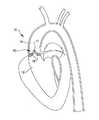
図1は、狭窄しかつ石灰化した大動脈弁16を有する心臓10の左心室12、大動脈14及び大動脈弁16の断面図である。図1に示すように、狭窄しかつ石灰化した大動脈弁16の開口部17の大きさが制限され、弁尖18がカルシウム沈着及び繊維性組織により厚くなっている。厚くなった弁尖18及び小さい開口部17は、心臓からの血流を制限し、心臓10の過労と心拍出量の低下とを生じさせる。前記したように、現在の治療法には、弁の置換又はバルーンで弁輪を広げることがある。 FIG. 1 is a cross-sectional view of the
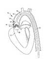
図2は、治療用のバルーン22が弁尖18の両側に配置されている状態の大動脈弁16の断面図である。バルーン22は、柔軟な材料又は非柔軟な材料で形成されている。バルーン22は、図2に示すように、細長い管23の端部にある。バルーン22は、管23の膨張用内腔25を共有する、長さ方向に間隔を置かれた2つの部屋24、26を有する。これに代え、部屋24、26は同一の膨張用流体通路を共有しなくてもよい。部屋24、26は、部屋24が弁尖18の一方の側に位置しかつ部屋26が弁尖18の他方の側に位置するように長さ方向に間隔を置かれている。部屋24、26は、例えば、生理食塩水と造影剤との混合物で膨張させられている。各部屋24、26は、後記するように、決められた時刻に衝撃波を送るために電気アークを発生させる電極を収容する。前記衝撃波は、カルシウム沈着を破壊する効果を最大化するために弁尖18の両側に同時に作用するように同期させられる。このような衝撃波は、例えば、2008年6月13日付けの出願第61/061,170号の明細書に記載されている方法で発せられかつ心臓10のR波にも同期させられたものとすることができる。この出願は、その全体が本明細書に組み込まれる。 FIG. 2 is a cross-sectional view of the
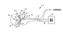
図3は、本発明に係る弁形成システム11の概略図である。弁形成システム11はデュアル衝撃波バルーン22を含む。バルーン22は、高圧電源30に接続された高電圧カテーテル32を受け入れている。前記概略図は、大動脈弁16の弁尖18の上方及び下方にある部屋24、26の位置を示す。前記したように、前記衝撃波は、弁尖18のカルシウム沈着をより効果的に破壊するために弁尖18の相対する両側に作用する。前記弁輪はこの配置で治療される。高電圧カテーテル32は、バルーン22の部屋24、26に配置された、同軸状に配置された電極である電極対34、36を備える。電極対36は、第1のケーブルの端部にあり、中心導体33と、外側の導電性シールド35とを有する。電極対34は、第2のケーブルの端部にあり、中心導体37と、外側の導電性シールド39とを有する。電源30からの高電圧パルスが、バルーン22の部屋24、26の中の流体の中に衝撃波を発生させるために、前記した出願第61/061,170号の明細書に記載されている方法で電極対34、36に加えられる。前記衝撃波は、大動脈弁16を開くために弁尖18及び前記弁輪のカルシウム沈着及び繊維性組織を破壊するように弁尖18及び前記弁輪に作用する。 FIG. 3 is a schematic view of an annuloplasty system 11 according to the present invention. The annuloplasty system 11 includes a dual
図4は、細長い管43の端部にある他の弁形成用衝撃波バルーン42を示す。バルーン42は大動脈弁16の前記弁輪の中に配置されている。バルーン42は、前記弁輪の中に受け入れられる、直径が小さい部分を有する。バルーン42は、電極対46まで伸びる高電圧カテーテル44を備える。電極対46は、前記した実施例のように、同軸状に配置された一対の電極であり、中心導体が一方の電極の少なくとも一部を形成し、外側の導電性シールドが他方の電極の少なくとも一部を形成している。カテーテル44及び電極対46は、前記したように、衝撃波を発生させる。このような配置は弁尖18からカルシウムを除去する。この配置は、弁尖18からカルシウムを除去するのみならず、前記弁輪を柔軟にし、その直径を長くする。しがたって、バルーン42は、前記弁輪の直径を変更するために該弁輪に拡張のための圧力を直接的に加えるという利点をもたらす。 FIG. 4 shows another annuloplasty
本発明の特定の実施例を示し、説明したが、修正がなされてもよく、本発明は、その真の精神及び範囲に含まれる全ての変更及び修正に及ぶ。 While particular embodiments of the present invention have been shown and described, modifications may be made and the invention extends to all changes and modifications falling within the true spirit and scope of the invention.
11 弁形成システム
16 大動脈弁
18 弁尖
22、42 バルーン
23、43 管
24、26 部屋
25 内腔
30 高圧電源
32、44 高電圧カテーテル
33、37 中心導体
34、36、46 電極対
35、39 導電性シールド11
Claims (46)
Translated fromJapanese前記バルーンの中の衝撃波発生装置であって弁に作用するために前記流体を経て伝わる衝撃波を発生させる衝撃波発生装置とを含む、弁形成システム。A fluid inflatable balloon disposed adjacent to the leaflets;
A valve formation system comprising a shock wave generator in the balloon for generating a shock wave transmitted through the fluid to act on the valve.
前記弁尖の相対する両側に配置される、流体により膨張可能なバルーンと、
前記バルーンの中の衝撃波発生装置であって前記弁尖と前記弁輪とに作用するために前記流体を経て伝わる衝撃波を発生させる衝撃波発生装置とを含む、弁形成システム。An annuloplasty system for treating a valve having a leaflet and an annulus,
A fluid inflatable balloon disposed on opposite sides of the leaflet;
A valve formation system comprising a shock wave generator in the balloon for generating a shock wave transmitted through the fluid to act on the valve leaflets and the valve annulus.
前記弁尖に隣接して前記弁輪の中に配置される、流体により膨張可能なバルーンと、
前記バルーンの中の衝撃波発生装置であって前記弁尖と前記弁輪とに作用するために前記流体を経て伝わる衝撃波を発生させる衝撃波発生装置とを含む、弁形成システム。An annuloplasty system for treating a valve having a leaflet and an annulus,
A fluid inflatable balloon disposed in the annulus adjacent to the leaflet;
A valve formation system comprising a shock wave generator in the balloon for generating a shock wave transmitted through the fluid to act on the valve leaflets and the valve annulus.
前記キャリアにより搬送されるバルーンであって該バルーンを膨張させる流体を受け入れるバルーンと、
前記バルーンの中の同軸状に配置された少なくとも一対の電極を備える少なくとも1つのアーク発生器であって前記バルーンの中に機械的な衝撃波を生じさせる少なくとも1つのアーク発生器とを含む、カテーテルシステム。An elongated carrier,
A balloon carried by the carrier and receiving a fluid for inflating the balloon;
A catheter system comprising: at least one arc generator comprising at least a pair of coaxially disposed electrodes in the balloon, wherein the arc generator generates a mechanical shock wave in the balloon; .
前記弁尖に隣接してバルーンを配置すること、
前記バルーンを流体で膨張させること、
前記弁尖と前記弁輪とに作用するために前記流体を経て伝わる衝撃波を前記バルーンの中に発生させることを含む、弁形成方法。An annuloplasty method for treating a valve having a leaflet and an annulus,
Placing a balloon adjacent to the leaflets;
Inflating the balloon with a fluid;
A method of forming a valve comprising generating a shock wave in the balloon that travels through the fluid to act on the leaflet and the annulus.
Applications Claiming Priority (3)
| Application Number | Priority Date | Filing Date | Title |
|---|---|---|---|
| US11160008P | 2008-11-05 | 2008-11-05 | |
| US61/111,600 | 2008-11-05 | ||
| PCT/US2009/063354WO2010054048A2 (en) | 2008-11-05 | 2009-11-05 | Shockwave valvuloplasty catheter system |
Related Child Applications (2)
| Application Number | Title | Priority Date | Filing Date |
|---|---|---|---|
| JP2015036444ADivisionJP6081510B2 (en) | 2008-11-05 | 2015-02-26 | Shock wave valve forming catheter system |
| JP2016143049ADivisionJP6246277B2 (en) | 2008-11-05 | 2016-07-21 | Shock wave valve forming catheter system |
Publications (2)
| Publication Number | Publication Date |
|---|---|
| JP2012508042Atrue JP2012508042A (en) | 2012-04-05 |
| JP6029828B2 JP6029828B2 (en) | 2016-11-24 |
Family
ID=42132311
Family Applications (3)
| Application Number | Title | Priority Date | Filing Date |
|---|---|---|---|
| JP2011534914AActiveJP6029828B2 (en) | 2008-11-05 | 2009-11-05 | Shock wave valve forming catheter system |
| JP2015036444AActiveJP6081510B2 (en) | 2008-11-05 | 2015-02-26 | Shock wave valve forming catheter system |
| JP2016143049AActiveJP6246277B2 (en) | 2008-11-05 | 2016-07-21 | Shock wave valve forming catheter system |
Family Applications After (2)
| Application Number | Title | Priority Date | Filing Date |
|---|---|---|---|
| JP2015036444AActiveJP6081510B2 (en) | 2008-11-05 | 2015-02-26 | Shock wave valve forming catheter system |
| JP2016143049AActiveJP6246277B2 (en) | 2008-11-05 | 2016-07-21 | Shock wave valve forming catheter system |
Country Status (7)
| Country | Link |
|---|---|
| US (7) | US9044618B2 (en) |
| EP (1) | EP2362798B1 (en) |
| JP (3) | JP6029828B2 (en) |
| CN (1) | CN102271748B (en) |
| AU (1) | AU2009313507B2 (en) |
| CA (1) | CA2779600C (en) |
| WO (1) | WO2010054048A2 (en) |
Cited By (34)
| Publication number | Priority date | Publication date | Assignee | Title |
|---|---|---|---|---|
| JP2015522344A (en)* | 2012-06-27 | 2015-08-06 | ショックウェーブ メディカル, インコーポレイテッド | Shock wave balloon catheter with multiple shock wave sources |
| JP2015524709A (en)* | 2012-08-08 | 2015-08-27 | ショックウェーブ メディカル, インコーポレイテッド | Shock wave valve formation with multiple balloons |
| JP2015525657A (en)* | 2012-08-17 | 2015-09-07 | ショックウェーブ メディカル, インコーポレイテッド | Shock wave catheter system with arc preconditioning |
| JP2015528327A (en)* | 2012-08-06 | 2015-09-28 | ショックウェーブ メディカル, インコーポレイテッド | Thin electrodes for shock wave catheters for angioplasty |
| JP2015528329A (en)* | 2012-08-06 | 2015-09-28 | ショックウェーブ メディカル, インコーポレイテッド | Shock wave catheter |
| JP2015531659A (en)* | 2012-09-13 | 2015-11-05 | ショックウェーブ メディカル, インコーポレイテッド | Shock wave catheter with energy control |
| JP2017516636A (en)* | 2014-06-05 | 2017-06-22 | セントレ・ホスピタリエ・ユニヴェルシテール・デ・サン−エティエンヌ | Transcatheter device for ablating calcified tissue from aortic leaflets |
| US9814476B2 (en) | 2011-11-08 | 2017-11-14 | Shockwave Medical, Inc. | Shock wave valvuloplasty device with moveable shock wave generator |
| US10039561B2 (en) | 2008-06-13 | 2018-08-07 | Shockwave Medical, Inc. | Shockwave balloon catheter system |
| US10149690B2 (en) | 2008-11-05 | 2018-12-11 | Shockwave Medical, Inc. | Shockwave valvuloplasty catheter system |
| US10357264B2 (en) | 2016-12-06 | 2019-07-23 | Shockwave Medical, Inc. | Shock wave balloon catheter with insertable electrodes |
| US10517620B2 (en) | 2012-09-13 | 2019-12-31 | Shockwave Medical, Inc. | Shock wave catheter system with energy control |
| US10646240B2 (en) | 2016-10-06 | 2020-05-12 | Shockwave Medical, Inc. | Aortic leaflet repair using shock wave applicators |
| US10702293B2 (en) | 2008-06-13 | 2020-07-07 | Shockwave Medical, Inc. | Two-stage method for treating calcified lesions within the wall of a blood vessel |
| US10709462B2 (en) | 2017-11-17 | 2020-07-14 | Shockwave Medical, Inc. | Low profile electrodes for a shock wave catheter |
| US10966737B2 (en) | 2017-06-19 | 2021-04-06 | Shockwave Medical, Inc. | Device and method for generating forward directed shock waves |
| US11020135B1 (en) | 2017-04-25 | 2021-06-01 | Shockwave Medical, Inc. | Shock wave device for treating vascular plaques |
| US11478261B2 (en) | 2019-09-24 | 2022-10-25 | Shockwave Medical, Inc. | System for treating thrombus in body lumens |
| US11596423B2 (en) | 2018-06-21 | 2023-03-07 | Shockwave Medical, Inc. | System for treating occlusions in body lumens |
| US11992232B2 (en) | 2020-10-27 | 2024-05-28 | Shockwave Medical, Inc. | System for treating thrombus in body lumens |
| US12011185B2 (en) | 2021-10-19 | 2024-06-18 | Shockwave Medical, Inc. | Intravascular lithotripsy catheter with interfering shock waves |
| US12023098B2 (en) | 2021-10-05 | 2024-07-02 | Shockwave Medical, Inc. | Lesion crossing shock wave catheter |
| US12035932B1 (en) | 2023-04-21 | 2024-07-16 | Shockwave Medical, Inc. | Intravascular lithotripsy catheter with slotted emitter bands |
| US12064129B2 (en) | 2015-11-18 | 2024-08-20 | Shockwave Medical, Inc. | Shock wave electrodes |
| US12089861B2 (en) | 2021-08-05 | 2024-09-17 | Nextern Innovation, Llc | Intravascular lithotripsy system and device |
| US12178458B1 (en) | 2024-05-16 | 2024-12-31 | Shockwave Medical, Inc. | Guidewireless shock wave catheters |
| US12220141B2 (en) | 2023-06-29 | 2025-02-11 | Shockwave Medical, Inc. | Catheter system with independently controllable bubble and arc generation |
| US12232755B2 (en) | 2020-12-11 | 2025-02-25 | Shockwave Medical, Inc. | Lesion crossing shock wave catheter |
| US12274460B2 (en) | 2019-09-24 | 2025-04-15 | Shockwave Medical, Inc. | Lesion crossing shock wave catheter |
| US12290268B2 (en) | 2023-03-31 | 2025-05-06 | Shockwave Medical, Inc. | Shockwave catheters for treating rhinosinusitis |
| US12402899B2 (en) | 2023-11-30 | 2025-09-02 | Shockwave Medical, Inc. | Systems, devices, and methods for generating shock waves in a forward direction |
| US12426938B2 (en) | 2019-09-24 | 2025-09-30 | Shockwave Medical, Inc. | Low profile electrodes for a shock wave catheter |
| US12426904B2 (en) | 2023-11-17 | 2025-09-30 | Shockwave Medical, Inc. | Intravascular lithotripsy catheter with oscillating impactor |
| US12433620B2 (en) | 2024-02-23 | 2025-10-07 | Shockwave Medical, Inc. | Locus emitter shock wave catheter devices with increased longevity and higher sonic output |
Families Citing this family (66)
| Publication number | Priority date | Publication date | Assignee | Title |
|---|---|---|---|---|
| US8750983B2 (en) | 2004-09-20 | 2014-06-10 | P Tech, Llc | Therapeutic system |
| US20100036294A1 (en) | 2008-05-07 | 2010-02-11 | Robert Mantell | Radially-Firing Electrohydraulic Lithotripsy Probe |
| US9072534B2 (en) | 2008-06-13 | 2015-07-07 | Shockwave Medical, Inc. | Non-cavitation shockwave balloon catheter system |
| US9180280B2 (en)* | 2008-11-04 | 2015-11-10 | Shockwave Medical, Inc. | Drug delivery shockwave balloon catheter system |
| DK3117784T3 (en) | 2009-07-08 | 2019-04-08 | Sanuwave Inc | USE OF INTRACORPORAL PRESSURE SHOCK WAVES IN MEDICINE |
| US20120116289A1 (en)* | 2010-11-09 | 2012-05-10 | Daniel Hawkins | Shockwave valvuloplasty device with guidewire and debris basket |
| US20120203255A1 (en)* | 2011-02-04 | 2012-08-09 | Daniel Hawkins | High pressure balloon shockwave catheter and method |
| WO2013169807A1 (en)* | 2012-05-07 | 2013-11-14 | Djt, Llc. | Non-cavitation shockwave balloon catheter system |
| US8888709B2 (en)* | 2012-09-12 | 2014-11-18 | Boston Scientific Scimed, Inc. | Method and apparatus for sensing and avoiding cardiac conduction system during valve deployment |
| CA3075128C (en) | 2013-03-11 | 2022-07-19 | Northgate Technologies Inc. | Unfocused electrohydraulic lithotripter |
| US10842567B2 (en) | 2013-03-13 | 2020-11-24 | The Spectranetics Corporation | Laser-induced fluid filled balloon catheter |
| US9320530B2 (en) | 2013-03-13 | 2016-04-26 | The Spectranetics Corporation | Assisted cutting balloon |
| US10201387B2 (en) | 2013-03-13 | 2019-02-12 | The Spectranetics Corporation | Laser-induced fluid filled balloon catheter |
| US9730715B2 (en) | 2014-05-08 | 2017-08-15 | Shockwave Medical, Inc. | Shock wave guide wire |
| US11246659B2 (en) | 2014-08-25 | 2022-02-15 | The Spectranetics Corporation | Liquid laser-induced pressure wave emitting catheter sheath |
| US20160135828A1 (en) | 2014-11-14 | 2016-05-19 | Shockwave Medical, Inc. | Shock wave valvuloplasty device and methods |
| WO2016109739A1 (en) | 2014-12-30 | 2016-07-07 | The Spectranetics Corporation | Electrically-induced pressure wave emitting catheter sheath |
| EP3240603B1 (en) | 2014-12-30 | 2019-05-01 | The Spectranetics Corporation | Laser-induced fluid filled balloon catheter |
| US11058492B2 (en) | 2014-12-30 | 2021-07-13 | The Spectranetics Corporation | Laser-induced pressure wave emitting catheter sheath |
| US10226265B2 (en) | 2016-04-25 | 2019-03-12 | Shockwave Medical, Inc. | Shock wave device with polarity switching |
| EP3484421A1 (en) | 2016-07-13 | 2019-05-22 | Boston Scientific Scimed Inc. | Apparatus and method for maintaining patency in a vessel adjacent to nearby surgery |
| US10441300B2 (en) | 2017-04-19 | 2019-10-15 | Shockwave Medical, Inc. | Drug delivery shock wave balloon catheter system |
| US10561428B2 (en) | 2017-04-21 | 2020-02-18 | Boston Scientific Scimed, Inc. | Lithotripsy angioplasty devices and methods |
| WO2018194980A1 (en) | 2017-04-21 | 2018-10-25 | Boston Scientific Scimed, Inc. | Lithotripsy angioplasty devices and methods |
| EP3648678A4 (en) | 2017-07-06 | 2021-03-24 | Raghuveer Basude | TISSUE GRIPPING DEVICES AND RELATED PROCEDURES |
| NL2019807B1 (en) | 2017-10-26 | 2019-05-06 | Boston Scient Scimed Inc | Shockwave generating device |
| US11071557B2 (en) | 2017-10-19 | 2021-07-27 | Medtronic Vascular, Inc. | Catheter for creating pulse wave within vasculature |
| US11103262B2 (en) | 2018-03-14 | 2021-08-31 | Boston Scientific Scimed, Inc. | Balloon-based intravascular ultrasound system for treatment of vascular lesions |
| US11819229B2 (en) | 2019-06-19 | 2023-11-21 | Boston Scientific Scimed, Inc. | Balloon surface photoacoustic pressure wave generation to disrupt vascular lesions |
| WO2020014312A1 (en)* | 2018-07-10 | 2020-01-16 | Boston Scientific Scimed, Inc. | Occlusive device with expandable member |
| CN109223100A (en)* | 2018-09-03 | 2019-01-18 | 沛嘉医疗科技(苏州)有限公司 | It is a kind of for treating the device and its application method of heart valve and angiosteosis |
| WO2020086361A1 (en) | 2018-10-24 | 2020-04-30 | Boston Scientific Scimed, Inc. | Photoacoustic pressure wave generation for intravascular calcification disruption |
| US11464658B2 (en) | 2018-10-25 | 2022-10-11 | Medtronic Vascular, Inc. | Implantable medical device with cavitation features |
| US11357958B2 (en) | 2018-10-25 | 2022-06-14 | Medtronic Vascular, Inc. | Devices and techniques for cardiovascular intervention |
| US11266817B2 (en) | 2018-10-25 | 2022-03-08 | Medtronic Vascular, Inc. | Cavitation catheter |
| US11717139B2 (en) | 2019-06-19 | 2023-08-08 | Bolt Medical, Inc. | Plasma creation via nonaqueous optical breakdown of laser pulse energy for breakup of vascular calcium |
| US12402946B2 (en) | 2019-06-19 | 2025-09-02 | Boston Scientific Scimed, Inc. | Breakdown of laser pulse energy for breakup of vascular calcium |
| US11399862B2 (en) | 2019-06-24 | 2022-08-02 | Boston Scientific Scimed, Inc. | Propulsion system for inertial energy transfer to disrupt vascular lesions |
| US11660427B2 (en) | 2019-06-24 | 2023-05-30 | Boston Scientific Scimed, Inc. | Superheating system for inertial impulse generation to disrupt vascular lesions |
| US12280223B2 (en) | 2019-06-26 | 2025-04-22 | Boston Scientific Scimed, Inc. | Focusing element for plasma system to disrupt vascular lesions |
| CN110811762A (en)* | 2019-08-08 | 2020-02-21 | 谱创医疗科技(上海)有限公司 | Shock wave enhanced drug delivery catheter |
| DE112020004287T5 (en)* | 2019-09-11 | 2022-06-09 | North Star Medical Inc. | CATHETER, SHEATH OR DILATOR FOR DECALCIFICATION OF HEART VALVES AND METHOD OF USE THEREOF |
| US11583339B2 (en) | 2019-10-31 | 2023-02-21 | Bolt Medical, Inc. | Asymmetrical balloon for intravascular lithotripsy device and method |
| US12102384B2 (en) | 2019-11-13 | 2024-10-01 | Bolt Medical, Inc. | Dynamic intravascular lithotripsy device with movable energy guide |
| US12274497B2 (en) | 2019-12-18 | 2025-04-15 | Bolt Medical, Inc. | Multiplexer for laser-driven intravascular lithotripsy device |
| US12011184B2 (en) | 2020-02-10 | 2024-06-18 | Elixir Medical Corporation | Methods and apparatus for plaque disruption |
| US11672599B2 (en) | 2020-03-09 | 2023-06-13 | Bolt Medical, Inc. | Acoustic performance monitoring system and method within intravascular lithotripsy device |
| US20210290286A1 (en) | 2020-03-18 | 2021-09-23 | Bolt Medical, Inc. | Optical analyzer assembly and method for intravascular lithotripsy device |
| US11707323B2 (en) | 2020-04-03 | 2023-07-25 | Bolt Medical, Inc. | Electrical analyzer assembly for intravascular lithotripsy device |
| US12295654B2 (en) | 2020-06-03 | 2025-05-13 | Boston Scientific Scimed, Inc. | System and method for maintaining balloon integrity within intravascular lithotripsy device with plasma generator |
| US12207870B2 (en) | 2020-06-15 | 2025-01-28 | Boston Scientific Scimed, Inc. | Spectroscopic tissue identification for balloon intravascular lithotripsy guidance |
| US20220071704A1 (en)* | 2020-09-09 | 2022-03-10 | Bolt Medical, Inc. | Valvuloplasty treatment system and method |
| US12016610B2 (en) | 2020-12-11 | 2024-06-25 | Bolt Medical, Inc. | Catheter system for valvuloplasty procedure |
| WO2022125525A1 (en)* | 2020-12-11 | 2022-06-16 | Bolt Medical, Inc. | Catheter system for valvuloplasty procedure |
| EP4277548B1 (en) | 2021-01-12 | 2025-06-04 | Bolt Medical, Inc. | Balloon assembly for valvuloplasty catheter system |
| US11672585B2 (en) | 2021-01-12 | 2023-06-13 | Bolt Medical, Inc. | Balloon assembly for valvuloplasty catheter system |
| US11648057B2 (en) | 2021-05-10 | 2023-05-16 | Bolt Medical, Inc. | Optical analyzer assembly with safety shutdown system for intravascular lithotripsy device |
| US11806075B2 (en) | 2021-06-07 | 2023-11-07 | Bolt Medical, Inc. | Active alignment system and method for laser optical coupling |
| US11957369B2 (en) | 2021-08-05 | 2024-04-16 | Nextern Innovation, Llc | Intravascular lithotripsy systems and methods |
| US11896248B2 (en) | 2021-08-05 | 2024-02-13 | Nextern Innovation, Llc | Systems, devices and methods for generating subsonic pressure waves in intravascular lithotripsy |
| US11877761B2 (en) | 2021-08-05 | 2024-01-23 | Nextern Innovation, Llc | Systems, devices and methods for monitoring voltage and current and controlling voltage of voltage pulse generators |
| US11801066B2 (en) | 2021-08-05 | 2023-10-31 | Nextern Innovation, Llc | Systems, devices and methods for selection of arc location within a lithoplasty balloon spark gap |
| US11839391B2 (en) | 2021-12-14 | 2023-12-12 | Bolt Medical, Inc. | Optical emitter housing assembly for intravascular lithotripsy device |
| US12294498B2 (en) | 2022-07-22 | 2025-05-06 | Red Hat, Inc. | Real time qubit allocation for dynamic network topographies |
| CN115414089B (en)* | 2022-10-10 | 2025-04-08 | 江苏朴芃医疗科技有限公司 | Shockwave Therapy Catheter System |
| WO2025171173A1 (en) | 2024-02-08 | 2025-08-14 | IV-X Medical, LLC | Intravascular lithotripsy system |
Citations (8)
| Publication number | Priority date | Publication date | Assignee | Title |
|---|---|---|---|---|
| JPH0363059A (en)* | 1989-04-26 | 1991-03-19 | Advanced Cardiovascular Syst Inc | Blood flow measurement using self-irrigation catheter for blood vessel formation and its device |
| JPH1099444A (en)* | 1996-09-27 | 1998-04-21 | Advanced Cardeovascular Syst Inc | Vibratory stent to open calcified lesion part |
| JPH10314177A (en)* | 1997-04-26 | 1998-12-02 | Convergenza Ag | Device with treating catheter |
| US20010044596A1 (en)* | 2000-05-10 | 2001-11-22 | Ali Jaafar | Apparatus and method for treatment of vascular restenosis by electroporation |
| JP2004357792A (en)* | 2003-06-02 | 2004-12-24 | Keio Gijuku | Apparatus for preventing and treating vascular restenosis by sound pressure wave induced by high intensity pulsed light irradiation |
| WO2007088546A2 (en)* | 2006-02-02 | 2007-08-09 | Releaf Medical Ltd. | Shock-wave generating device, such as for the treatment of calcific aortic stenosis |
| JP2008506447A (en)* | 2004-07-14 | 2008-03-06 | バイ−パス, インコーポレイテッド | Material delivery system |
| JP2011528963A (en)* | 2008-07-27 | 2011-12-01 | ゴラン、エレズ | Fracture of calcified part in heart valve |
Family Cites Families (222)
| Publication number | Priority date | Publication date | Assignee | Title |
|---|---|---|---|---|
| US2916647A (en) | 1959-03-18 | 1959-12-08 | Roscoe H George | Spark gap impulse generator |
| US3413976A (en) | 1963-07-29 | 1968-12-03 | G Elektrotekhnichesky Zd Vef | Arrangement for removal of concretions from urinary tract |
| BE654594A (en) | 1963-10-28 | 1965-04-20 | ||
| US3583766A (en) | 1969-05-22 | 1971-06-08 | Louis R Padberg Jr | Apparatus for facilitating the extraction of minerals from the ocean floor |
| AT309663B (en) | 1971-05-14 | 1973-08-27 | Phil Heinz Schmidt Kloiber Dr | Device for destroying stones in the bladder, ureter, kidney and the like. like |
| CH574734A5 (en) | 1973-10-12 | 1976-04-30 | Dornier System Gmbh | |
| US3902499A (en) | 1974-01-02 | 1975-09-02 | Hoffman Saul | Stone disintegrator |
| US4027674A (en)* | 1975-06-06 | 1977-06-07 | Tessler Arthur N | Method and device for removing concretions within human ducts |
| US4030505A (en)* | 1975-11-28 | 1977-06-21 | Calculus Instruments Ltd. | Method and device for disintegrating stones in human ducts |
| US4900303A (en) | 1978-03-10 | 1990-02-13 | Lemelson Jerome H | Dispensing catheter and method |
| JPS6029828B2 (en) | 1978-11-20 | 1985-07-12 | 株式会社ウオルブロ−・フア−イ−スト | Rotary throttle valve type carburetor |
| DE3038445A1 (en) | 1980-10-11 | 1982-05-27 | Dornier Gmbh, 7990 Friedrichshafen | Pressure wave generator for diagnosis and therapy - has spark gap in inflatable balloon at end of catheter |
| US4445509A (en) | 1982-02-04 | 1984-05-01 | Auth David C | Method and apparatus for removal of enclosed abnormal deposits |
| US4685458A (en) | 1984-03-01 | 1987-08-11 | Vaser, Inc. | Angioplasty catheter and method for use thereof |
| JPS60191353U (en) | 1984-05-25 | 1985-12-18 | 日立工機株式会社 | Ink ribbon feeding control device |
| US4671254A (en) | 1985-03-01 | 1987-06-09 | Memorial Hospital For Cancer And Allied Diseases | Non-surgical method for suppression of tumor growth |
| EP0196353A3 (en) | 1985-04-04 | 1987-02-04 | DORNIER SYSTEM GmbH | Device for the avoidance or reduction of pain in extracorporal lithotripsy |
| US5176675A (en) | 1985-04-24 | 1993-01-05 | The General Hospital Corporation | Use of lasers to break down objects for removal from within the body |
| DE3543881C1 (en) | 1985-12-12 | 1987-03-26 | Dornier Medizintechnik | Underwater electrode for non-contact lithotripsy |
| JPS6299210U (en)* | 1985-12-12 | 1987-06-24 | ||
| CA1293663C (en) | 1986-01-06 | 1991-12-31 | David Christopher Auth | Transluminal microdissection device |
| JPS62275446A (en) | 1986-05-21 | 1987-11-30 | オリンパス光学工業株式会社 | Discharge stone crushing apparatus |
| US4662126A (en) | 1986-05-23 | 1987-05-05 | Fike Corporation | Vibration resistant explosion control vent |
| US4741405A (en) | 1987-01-06 | 1988-05-03 | Tetra Corporation | Focused shock spark discharge drill using multiple electrodes |
| US4878495A (en) | 1987-05-15 | 1989-11-07 | Joseph Grayzel | Valvuloplasty device with satellite expansion means |
| US4813934A (en) | 1987-08-07 | 1989-03-21 | Target Therapeutics | Valved catheter device and method |
| JPH01145074A (en) | 1987-12-01 | 1989-06-07 | Terumo Corp | Balloon catheter |
| US5154722A (en)* | 1988-05-05 | 1992-10-13 | Circon Corporation | Electrohydraulic probe having a controlled discharge path |
| WO1989011311A1 (en) | 1988-05-18 | 1989-11-30 | Kasevich Associates, Inc. | Microwave balloon angioplasty |
| US4909252A (en) | 1988-05-26 | 1990-03-20 | The Regents Of The Univ. Of California | Perfusion balloon catheter |
| EP0355177A1 (en) | 1988-08-17 | 1990-02-28 | Siemens Aktiengesellschaft | Apparatus for the contactless desintegration of concrements in a living thing body |
| US4955377A (en)* | 1988-10-28 | 1990-09-11 | Lennox Charles D | Device and method for heating tissue in a patient's body |
| AU4945490A (en) | 1989-01-06 | 1990-08-01 | Angioplasty Systems Inc. | Electrosurgical catheter for resolving atherosclerotic plaque |
| US5425735A (en) | 1989-02-22 | 1995-06-20 | Psi Medical Products, Inc. | Shielded tip catheter for lithotripsy |
| US5281231A (en) | 1989-02-22 | 1994-01-25 | Physical Sciences, Inc. | Impact lithotrypsy |
| US5246447A (en) | 1989-02-22 | 1993-09-21 | Physical Sciences, Inc. | Impact lithotripsy |
| US6146358A (en) | 1989-03-14 | 2000-11-14 | Cordis Corporation | Method and apparatus for delivery of therapeutic agent |
| US5078717A (en) | 1989-04-13 | 1992-01-07 | Everest Medical Corporation | Ablation catheter with selectively deployable electrodes |
| DE3937904C2 (en) | 1989-11-15 | 1994-05-11 | Dornier Medizintechnik | Improvement of the ignition behavior on an underwater spark gap |
| US5002085A (en) | 1990-02-12 | 1991-03-26 | Bs&B Safety Systems, Inc. | Low pressure non-fragmenting rupture disks |
| US5709676A (en) | 1990-02-14 | 1998-01-20 | Alt; Eckhard | Synergistic treatment of stenosed blood vessels using shock waves and dissolving medication |
| US5061240A (en)* | 1990-04-02 | 1991-10-29 | George Cherian | Balloon tip catheter for venous valve ablation |
| US5057103A (en) | 1990-05-01 | 1991-10-15 | Davis Emsley A | Compressive intramedullary nail |
| DE4016054A1 (en)* | 1990-05-18 | 1991-11-21 | Dornier Medizintechnik | SPARK RANGE FOR LITHOTRIPSY |
| US5364393A (en) | 1990-07-02 | 1994-11-15 | Heart Technology, Inc. | Tissue dissipative recanalization catheter |
| US5103804A (en) | 1990-07-03 | 1992-04-14 | Boston Scientific Corporation | Expandable tip hemostatic probes and the like |
| US5152767A (en) | 1990-11-23 | 1992-10-06 | Northgate Technologies, Inc. | Invasive lithotripter with focused shockwave |
| US6524274B1 (en) | 1990-12-28 | 2003-02-25 | Scimed Life Systems, Inc. | Triggered release hydrogel drug delivery system |
| US5893840A (en) | 1991-01-04 | 1999-04-13 | Medtronic, Inc. | Releasable microcapsules on balloon catheters |
| US5102402A (en) | 1991-01-04 | 1992-04-07 | Medtronic, Inc. | Releasable coatings on balloon catheters |
| US5324255A (en) | 1991-01-11 | 1994-06-28 | Baxter International Inc. | Angioplasty and ablative devices having onboard ultrasound components and devices and methods for utilizing ultrasound to treat or prevent vasopasm |
| US5152768A (en) | 1991-02-26 | 1992-10-06 | Bhatta Krishna M | Electrohydraulic lithotripsy |
| US5116227A (en) | 1991-03-01 | 1992-05-26 | Endo Technic Corporation | Process for cleaning and enlarging passages |
| US5295958A (en)* | 1991-04-04 | 1994-03-22 | Shturman Cardiology Systems, Inc. | Method and apparatus for in vivo heart valve decalcification |
| US5395335A (en) | 1991-05-24 | 1995-03-07 | Jang; G. David | Universal mode vascular catheter system |
| CA2120516A1 (en) | 1991-10-03 | 1993-04-15 | Ralph De La Torre | Apparatus and method for vasodilation |
| US6406486B1 (en) | 1991-10-03 | 2002-06-18 | The General Hospital Corporation | Apparatus and method for vasodilation |
| US6179824B1 (en) | 1993-05-10 | 2001-01-30 | Arthrocare Corporation | System and methods for electrosurgical restenosis of body lumens |
| US5304134A (en) | 1992-01-17 | 1994-04-19 | Danforth Biomedical, Inc. | Lubricious yet bondable catheter channel sleeve for over-the-wire catheters |
| US5505702A (en) | 1992-04-09 | 1996-04-09 | Scimed Life Systems, Inc. | Balloon catheter for dilatation and perfusion |
| US5254121A (en) | 1992-05-22 | 1993-10-19 | Meditron Devices, Inc. | Method and device for removing concretions within human ducts |
| EP0571306A1 (en) | 1992-05-22 | 1993-11-24 | LASER MEDICAL TECHNOLOGY, Inc. | Apparatus and method for removal of deposits from the walls of body passages |
| US5362309A (en) | 1992-09-14 | 1994-11-08 | Coraje, Inc. | Apparatus and method for enhanced intravascular phonophoresis including dissolution of intravascular blockage and concomitant inhibition of restenosis |
| JPH06125915A (en) | 1992-10-21 | 1994-05-10 | Inter Noba Kk | Catheter type medical instrument |
| DE69417465T2 (en) | 1993-02-05 | 1999-07-22 | The Joe W. And Dorothy Dorsett Brown Foundation, New Orleans | Ultrasound balloon catheter for angioplasty |
| US5321715A (en) | 1993-05-04 | 1994-06-14 | Coherent, Inc. | Laser pulse format for penetrating an absorbing fluid |
| CA2118886C (en) | 1993-05-07 | 1998-12-08 | Dennis Vigil | Method and apparatus for dilatation of a stenotic vessel |
| CA2104414A1 (en) | 1993-08-19 | 1995-02-20 | Krishna M. Bhatta | Electrohydraulic lithotripsy |
| US5417208A (en) | 1993-10-12 | 1995-05-23 | Arrow International Investment Corp. | Electrode-carrying catheter and method of making same |
| IL109669A (en) | 1994-05-17 | 1997-09-30 | Hadasit Med Res Service | System and method for coronary angioplasty |
| US8025661B2 (en) | 1994-09-09 | 2011-09-27 | Cardiofocus, Inc. | Coaxial catheter instruments for ablation with radiant energy |
| US6113560A (en)* | 1994-09-21 | 2000-09-05 | Hmt High Medical Techologies | Method and device for generating shock waves for medical therapy, particularly for electro-hydraulic lithotripsy |
| US5603731A (en) | 1994-11-21 | 1997-02-18 | Whitney; Douglass G. | Method and apparatus for thwarting thrombosis |
| US5584843A (en) | 1994-12-20 | 1996-12-17 | Boston Scientific Corporation | Shaped wire multi-burr rotational ablation device |
| DE19504261A1 (en) | 1995-02-09 | 1996-09-12 | Krieg Gunther | Angioplasty catheter for dilating and / or opening blood vessels |
| US6090104A (en) | 1995-06-07 | 2000-07-18 | Cordis Webster, Inc. | Catheter with a spirally wound flat ribbon electrode |
| US5582578A (en) | 1995-08-01 | 1996-12-10 | Duke University | Method for the comminution of concretions |
| CN1204242A (en) | 1995-10-13 | 1999-01-06 | 血管转换公司 | Methods and devices for bypassing and/or other transvascular procedures for arterial blockages |
| US20020045890A1 (en) | 1996-04-24 | 2002-04-18 | The Regents Of The University O F California | Opto-acoustic thrombolysis |
| US6544276B1 (en) | 1996-05-20 | 2003-04-08 | Medtronic Ave. Inc. | Exchange method for emboli containment |
| EP1013142A4 (en) | 1996-08-05 | 2002-06-05 | Tetra Corp | Electrohydraulic pressure wave projectors |
| US5846218A (en)* | 1996-09-05 | 1998-12-08 | Pharmasonics, Inc. | Balloon catheters having ultrasonically driven interface surfaces and methods for their use |
| US6352535B1 (en) | 1997-09-25 | 2002-03-05 | Nanoptics, Inc. | Method and a device for electro microsurgery in a physiological liquid environment |
| DE19718512C1 (en)* | 1997-05-02 | 1998-06-25 | Hmt Ag | Production of shock waves for medical applications using spark discharge in water |
| DE19718513C5 (en) | 1997-05-02 | 2010-06-02 | Sanuwave, Inc., | Device for generating acoustic shock waves, in particular for medical use |
| US6024740A (en) | 1997-07-08 | 2000-02-15 | The Regents Of The University Of California | Circumferential ablation device assembly |
| US5931805A (en) | 1997-06-02 | 1999-08-03 | Pharmasonics, Inc. | Catheters comprising bending transducers and methods for their use |
| WO1999000060A1 (en) | 1997-06-26 | 1999-01-07 | Advanced Coronary Intervention | Electrosurgical catheter for resolving obstructions by radio frequency ablation |
| US6500174B1 (en) | 1997-07-08 | 2002-12-31 | Atrionix, Inc. | Circumferential ablation device assembly and methods of use and manufacture providing an ablative circumferential band along an expandable member |
| ATE433306T1 (en) | 1997-07-08 | 2009-06-15 | Univ California | DEVICE FOR CIRCUMFERENTIAL ABLATION |
| US6494890B1 (en) | 1997-08-14 | 2002-12-17 | Shturman Cardiology Systems, Inc. | Eccentric rotational atherectomy device |
| US6132444A (en) | 1997-08-14 | 2000-10-17 | Shturman Cardiology Systems, Inc. | Eccentric drive shaft for atherectomy device and method for manufacture |
| US6056722A (en) | 1997-09-18 | 2000-05-02 | Iowa-India Investments Company Limited Of Douglas | Delivery mechanism for balloons, drugs, stents and other physical/mechanical agents and methods of use |
| CA2306867A1 (en) | 1997-10-21 | 1999-04-29 | The Regents Of The University Of California | Photoacoustic removal of occlusions from blood vessels |
| EP0911804B1 (en) | 1997-10-24 | 2007-05-09 | MTS Europe GmbH | Method for the automatic adjustment of the distance between the electrodes of a spark gap in electrohydraulic shock wave generators |
| US6267747B1 (en)* | 1998-05-11 | 2001-07-31 | Cardeon Corporation | Aortic catheter with porous aortic root balloon and methods for inducing cardioplegic arrest |
| US6206283B1 (en) | 1998-12-23 | 2001-03-27 | At&T Corp. | Method and apparatus for transferring money via a telephone call |
| US6440124B1 (en) | 1998-07-22 | 2002-08-27 | Endovasix, Inc. | Flexible flow apparatus and method for the disruption of occlusions |
| US6755821B1 (en)* | 1998-12-08 | 2004-06-29 | Cardiocavitational Systems, Inc. | System and method for stimulation and/or enhancement of myocardial angiogenesis |
| US6210408B1 (en) | 1999-02-24 | 2001-04-03 | Scimed Life Systems, Inc. | Guide wire system for RF recanalization of vascular blockages |
| US6277138B1 (en) | 1999-08-17 | 2001-08-21 | Scion Cardio-Vascular, Inc. | Filter for embolic material mounted on expandable frame |
| US6398792B1 (en) | 1999-06-21 | 2002-06-04 | O'connor Lawrence | Angioplasty catheter with transducer using balloon for focusing of ultrasonic energy and method for use |
| DE19929112A1 (en)* | 1999-06-24 | 2001-01-11 | Ferton Holding Sa | Medical instrument for the treatment of biological tissue and method for transmitting pressure waves |
| US6524251B2 (en) | 1999-10-05 | 2003-02-25 | Omnisonics Medical Technologies, Inc. | Ultrasonic device for tissue ablation and sheath for use therewith |
| US20040249401A1 (en) | 1999-10-05 | 2004-12-09 | Omnisonics Medical Technologies, Inc. | Apparatus and method for an ultrasonic medical device with a non-compliant balloon |
| US6652547B2 (en) | 1999-10-05 | 2003-11-25 | Omnisonics Medical Technologies, Inc. | Apparatus and method of removing occlusions using ultrasonic medical device operating in a transverse mode |
| US20040097996A1 (en) | 1999-10-05 | 2004-05-20 | Omnisonics Medical Technologies, Inc. | Apparatus and method of removing occlusions using an ultrasonic medical device operating in a transverse mode |
| US6371971B1 (en) | 1999-11-15 | 2002-04-16 | Scimed Life Systems, Inc. | Guidewire filter and methods of use |
| US6589253B1 (en) | 1999-12-30 | 2003-07-08 | Advanced Cardiovascular Systems, Inc. | Ultrasonic angioplasty transmission wire |
| US6440061B1 (en) | 2000-03-24 | 2002-08-27 | Donald E. Wenner | Laparoscopic instrument system for real-time biliary exploration and stone removal |
| US6364894B1 (en) | 2000-06-12 | 2002-04-02 | Cordis Corporation | Method of making an angioplasty balloon catheter |
| US6413256B1 (en) | 2000-08-01 | 2002-07-02 | Csaba Truckai | Voltage threshold ablation method and apparatus |
| US7744595B2 (en) | 2000-08-01 | 2010-06-29 | Arqos Surgical, Inc. | Voltage threshold ablation apparatus |
| US6367203B1 (en) | 2000-09-11 | 2002-04-09 | Oklahoma Safety Equipment Co., Inc. | Rupture panel |
| US6638246B1 (en) | 2000-11-28 | 2003-10-28 | Scimed Life Systems, Inc. | Medical device for delivery of a biologically active material to a lumen |
| US20020082553A1 (en) | 2000-12-22 | 2002-06-27 | Advanced Cardiovascular Systems, Inc. | Balloon designs for angioplasty |
| DE10100974B4 (en)* | 2001-01-11 | 2004-07-08 | Hmt High Medical Technologies Ag | Device for generating shock waves |
| US6514203B2 (en) | 2001-02-12 | 2003-02-04 | Sonata Technologies Ltd. | Method for ultrasonic coronary thrombolysis |
| US6607003B1 (en) | 2001-04-23 | 2003-08-19 | Oklahoma Safety Equipment Co, | Gasket-lined rupture panel |
| US6666828B2 (en) | 2001-06-29 | 2003-12-23 | Medtronic, Inc. | Catheter system having disposable balloon |
| US7674258B2 (en) | 2002-09-24 | 2010-03-09 | Endoscopic Technologies, Inc. (ESTECH, Inc.) | Electrophysiology electrode having multiple power connections and electrophysiology devices including the same |
| US6740081B2 (en) | 2002-01-25 | 2004-05-25 | Applied Medical Resources Corporation | Electrosurgery with improved control apparatus and method |
| US7815596B2 (en) | 2002-02-28 | 2010-10-19 | Cordis Corporation | Localized fluid delivery having a porous applicator and methods for using the same |
| US7087061B2 (en) | 2002-03-12 | 2006-08-08 | Lithotech Medical Ltd | Method for intracorporeal lithotripsy fragmentation and apparatus for its implementation |
| US6989009B2 (en) | 2002-04-19 | 2006-01-24 | Scimed Life Systems, Inc. | Cryo balloon |
| US7829029B2 (en) | 2002-05-29 | 2010-11-09 | NanoVibronix, Inv. | Acoustic add-on device for biofilm prevention in urinary catheter |
| US7153315B2 (en) | 2002-06-11 | 2006-12-26 | Boston Scientific Scimed, Inc. | Catheter balloon with ultrasonic microscalpel blades |
| US20040082859A1 (en) | 2002-07-01 | 2004-04-29 | Alan Schaer | Method and apparatus employing ultrasound energy to treat body sphincters |
| US6866662B2 (en) | 2002-07-23 | 2005-03-15 | Biosense Webster, Inc. | Ablation catheter having stabilizing array |
| JP2004081374A (en) | 2002-08-26 | 2004-03-18 | Dairin Kk | Instrument for removing sediment in tubular organ |
| US20040097963A1 (en) | 2002-11-19 | 2004-05-20 | Seddon J. Michael | Method and apparatus for disintegrating urinary tract stones |
| US20040162508A1 (en) | 2003-02-19 | 2004-08-19 | Walter Uebelacker | Shock wave therapy method and device |
| DE10311659B4 (en) | 2003-03-14 | 2006-12-21 | Sws Shock Wave Systems Ag | Apparatus and method for optimized electrohydraulic pressure pulse generation |
| US7628785B2 (en) | 2003-06-13 | 2009-12-08 | Piezo Technologies | Endoscopic medical treatment involving acoustic ablation |
| US7744620B2 (en)* | 2003-07-18 | 2010-06-29 | Intervalve, Inc. | Valvuloplasty catheter |
| US7247269B2 (en) | 2003-07-21 | 2007-07-24 | Biosense Webster, Inc. | Method for making a spiral array ultrasound transducer |
| US7736362B2 (en)* | 2003-09-15 | 2010-06-15 | Boston Scientific Scimed, Inc. | Catheter balloons |
| JP4072580B2 (en) | 2003-09-25 | 2008-04-09 | ケイセイ医科工業株式会社 | Thrombectomy catheter |
| US20050090888A1 (en) | 2003-10-28 | 2005-04-28 | Hines Richard A. | Pleated stent assembly |
| WO2005065563A1 (en)* | 2003-12-31 | 2005-07-21 | Biosense Webster, Inc | Circumferential ablation device assembly with an expandable member |
| US20070282301A1 (en) | 2004-02-26 | 2007-12-06 | Segalescu Victor A | Dilatation Balloon Catheter Including External Means For Endoluminal Therapy And For Drug Activation |
| US7754047B2 (en) | 2004-04-08 | 2010-07-13 | Boston Scientific Scimed, Inc. | Cutting balloon catheter and method for blade mounting |
| KR101193709B1 (en) | 2004-04-19 | 2012-10-23 | 프로리듬, 인크. | Ablation devices with sensor structures |
| US7720521B2 (en) | 2004-04-21 | 2010-05-18 | Acclarent, Inc. | Methods and devices for performing procedures within the ear, nose, throat and paranasal sinuses |
| US7389148B1 (en) | 2004-05-05 | 2008-06-17 | Pacesetter, Inc. | Electrode design for defibrillation and/or sensing capabilities |
| CN101043914A (en) | 2004-07-14 | 2007-09-26 | 旁路公司 | Material delivery system |
| ITMI20041427A1 (en) | 2004-07-15 | 2004-10-15 | Univ Degli Studi Milano | SUMMARY OF ORGANOMETALLIC MOLECULES USABLE AS ORGANIC SUBSTANCE MARKERS |
| US8750983B2 (en) | 2004-09-20 | 2014-06-10 | P Tech, Llc | Therapeutic system |
| US20060069424A1 (en) | 2004-09-27 | 2006-03-30 | Xtent, Inc. | Self-constrained segmented stents and methods for their deployment |
| AU2004324043A1 (en) | 2004-10-02 | 2006-04-20 | Christoph Hans Huber | Methods and devices for repair or replacement of heart valves or adjacent tissue without the need for full cardiopulmonary support |
| US7309324B2 (en) | 2004-10-15 | 2007-12-18 | Futuremed Interventional, Inc. | Non-compliant medical balloon having an integral woven fabric layer |
| US20060184076A1 (en) | 2004-12-01 | 2006-08-17 | Gill Robert P | Ultrasonic device and method for treating stones within the body |
| JP5219518B2 (en) | 2004-12-09 | 2013-06-26 | ザ ファウンドリー, エルエルシー | Aortic valve repair |
| US20060241524A1 (en) | 2005-03-11 | 2006-10-26 | Qi Yu | Intravascular ultrasound catheter device and method for ablating atheroma |
| EP1714642A1 (en) | 2005-04-18 | 2006-10-25 | Bracco Research S.A. | Pharmaceutical composition comprising gas-filled microcapsules for ultrasound mediated delivery |
| US7853332B2 (en) | 2005-04-29 | 2010-12-14 | Medtronic, Inc. | Lead electrode for use in an MRI-safe implantable medical device |
| GB2426456B (en) | 2005-05-26 | 2010-10-27 | Leonid Shturman | Rotational device with eccentric abrasive element and method of use |
| US8162859B2 (en) | 2005-06-09 | 2012-04-24 | General Patent , LLC | Shock wave treatment device and method of use |
| EP2759276A1 (en) | 2005-06-20 | 2014-07-30 | Medtronic Ablation Frontiers LLC | Ablation catheter |
| US20070088380A1 (en) | 2005-10-14 | 2007-04-19 | Endocross Ltd. | Balloon catheter system for treating vascular occlusions |
| US8696656B2 (en) | 2005-11-18 | 2014-04-15 | Medtronic Cryocath Lp | System and method for monitoring bioimpedance and respiration |
| US20070239082A1 (en) | 2006-01-27 | 2007-10-11 | General Patent, Llc | Shock Wave Treatment Device |
| US20080077165A1 (en) | 2006-02-24 | 2008-03-27 | National University Of Ireland, Galway | Minimally Invasive Intravascular Treatment Device |
| US20070239253A1 (en) | 2006-04-06 | 2007-10-11 | Jagger Karl A | Oscillation assisted drug elution apparatus and method |
| US7651492B2 (en) | 2006-04-24 | 2010-01-26 | Covidien Ag | Arc based adaptive control system for an electrosurgical unit |
| US20070255270A1 (en) | 2006-04-27 | 2007-11-01 | Medtronic Vascular, Inc. | Intraluminal guidance system using bioelectric impedance |
| US20080097251A1 (en) | 2006-06-15 | 2008-04-24 | Eilaz Babaev | Method and apparatus for treating vascular obstructions |
| CN101505668A (en) | 2006-06-20 | 2009-08-12 | 奥尔特克斯公司 | Prosthetic valve implant site preparation techniques |
| CA2655391C (en) | 2006-06-21 | 2016-11-08 | Intrapace, Inc. | Endoscopic device delivery system |
| DE202006014285U1 (en) | 2006-09-13 | 2006-12-28 | Walz Elektronik Gmbh | Probe for generating an electro-hydraulic pressure wave for shattering concrete bodies has coil electrode wound around rod electrode at the end of a sheath |
| EP2076198A4 (en) | 2006-10-18 | 2009-12-09 | Minnow Medical Inc | Inducing desirable temperature effects on body tissue |
| US10220187B2 (en) | 2010-06-16 | 2019-03-05 | St. Jude Medical, Llc | Ablation catheter having flexible tip with multiple flexible electrode segments |
| US8663318B2 (en) | 2007-07-23 | 2014-03-04 | Hocor Cardiovascular Technologies Llc | Method and apparatus for percutaneous aortic valve replacement |
| CA2703345C (en) | 2007-10-22 | 2016-04-12 | Endocross Ltd. | Balloons and balloon catheter systems for treating vascular occlusions |
| IL188067A (en) | 2007-12-12 | 2011-12-29 | Lithotech Medical Ltd | Device for fragmenting and removing concretions from body ducts and cavities |
| US8466605B2 (en) | 2008-03-13 | 2013-06-18 | Ultrashape Ltd. | Patterned ultrasonic transducers |
| CN101532662B (en) | 2008-03-14 | 2013-01-02 | 烟台龙源电力技术股份有限公司 | Method for reducing nitrogen oxides by coal dust boiler of internal combustion burner |
| WO2009121017A1 (en) | 2008-03-27 | 2009-10-01 | The Regents Of The University Of California | Balloon catheter for reducing restenosis via irreversible electroporation |
| SG188921A1 (en) | 2008-04-08 | 2013-04-30 | Univ Arizona | Assemblies and methods for reducing warp and bow of a flexible substrate during semiconductor processing |
| US8900166B2 (en) | 2008-04-14 | 2014-12-02 | Avner Spector | Automatic adjustable voltage to stabilize pressure for shockwave medical therapy device |
| US8177801B2 (en) | 2008-04-18 | 2012-05-15 | Cardiovascular Systems, Inc. | Method and apparatus for increasing rotational amplitude of abrasive element on high-speed rotational atherectomy device |
| US20100036294A1 (en) | 2008-05-07 | 2010-02-11 | Robert Mantell | Radially-Firing Electrohydraulic Lithotripsy Probe |
| US9072534B2 (en) | 2008-06-13 | 2015-07-07 | Shockwave Medical, Inc. | Non-cavitation shockwave balloon catheter system |
| WO2009152352A2 (en)* | 2008-06-13 | 2009-12-17 | Aspen Medtech, Inc. | Shockwave balloon catheter system |
| US10702293B2 (en) | 2008-06-13 | 2020-07-07 | Shockwave Medical, Inc. | Two-stage method for treating calcified lesions within the wall of a blood vessel |
| US20130030431A1 (en) | 2008-06-13 | 2013-01-31 | Adams John M | Shock wave balloon catheter system with off center shock wave generator |
| US20100016862A1 (en) | 2008-07-16 | 2010-01-21 | Daniel Hawkins | Method of providing embolic protection and shockwave angioplasty therapy to a vessel |
| US7951111B2 (en) | 2008-10-10 | 2011-05-31 | Intervalve, Inc. | Valvuloplasty catheter and methods |
| US9180280B2 (en) | 2008-11-04 | 2015-11-10 | Shockwave Medical, Inc. | Drug delivery shockwave balloon catheter system |
| US9044618B2 (en) | 2008-11-05 | 2015-06-02 | Shockwave Medical, Inc. | Shockwave valvuloplasty catheter system |
| WO2010080886A1 (en) | 2009-01-09 | 2010-07-15 | Recor Medical, Inc. | Methods and apparatus for treatment of mitral valve in insufficiency |
| DK3117784T3 (en) | 2009-07-08 | 2019-04-08 | Sanuwave Inc | USE OF INTRACORPORAL PRESSURE SHOCK WAVES IN MEDICINE |
| EP2506781B1 (en) | 2009-12-05 | 2018-03-21 | Pi-R-Squared Ltd. | Device for fracturing calcifications in heart valves |
| US9005198B2 (en) | 2010-01-29 | 2015-04-14 | Ethicon Endo-Surgery, Inc. | Surgical instrument comprising an electrode |
| US9743980B2 (en) | 2010-02-24 | 2017-08-29 | Safepass Vascular Ltd | Method and system for assisting a wire guide to cross occluded ducts |
| WO2011126580A2 (en) | 2010-04-09 | 2011-10-13 | Minnow Medical, Inc. | Power generating and control apparatus for the treatment of tissue |
| US9192790B2 (en) | 2010-04-14 | 2015-11-24 | Boston Scientific Scimed, Inc. | Focused ultrasonic renal denervation |
| AU2011252976A1 (en) | 2010-05-12 | 2012-11-08 | Shifamed Holdings, Llc | Low profile electrode assembly |
| US9833373B2 (en) | 2010-08-27 | 2017-12-05 | Les Solutions Médicales Soundbite Inc. | Mechanical wave generator and method thereof |
| US20130123694A1 (en) | 2010-09-17 | 2013-05-16 | Angiometrix Corporation | Diagnostic kit and method for measuring balloon dimension in vivo |
| US20120116289A1 (en) | 2010-11-09 | 2012-05-10 | Daniel Hawkins | Shockwave valvuloplasty device with guidewire and debris basket |
| US9204922B2 (en) | 2010-12-01 | 2015-12-08 | Enable Urology, Llc | Method and apparatus for remodeling/profiling a tissue lumen, particularly in the urethral lumen in the prostate gland |
| US11246653B2 (en) | 2010-12-07 | 2022-02-15 | Boaz Avitall | Catheter systems for cardiac arrhythmia ablation |
| US8979840B2 (en) | 2010-12-17 | 2015-03-17 | St. Jude Medical, Atrial Fibrillation Division, Inc. | Irrigant distribution system for flexible electrodes |
| US20120203255A1 (en) | 2011-02-04 | 2012-08-09 | Daniel Hawkins | High pressure balloon shockwave catheter and method |
| BR112014009634A2 (en) | 2011-10-19 | 2017-05-09 | Mercator Medsystems Inc | preparation and therapeutic agent |
| US8574247B2 (en) | 2011-11-08 | 2013-11-05 | Shockwave Medical, Inc. | Shock wave valvuloplasty device with moveable shock wave generator |
| US8574248B2 (en) | 2011-12-12 | 2013-11-05 | Kassab Kughn Endovascular Devices | Catheter system with balloon-mounted plaque-modifying elements |
| US9642673B2 (en) | 2012-06-27 | 2017-05-09 | Shockwave Medical, Inc. | Shock wave balloon catheter with multiple shock wave sources |
| CN102765785A (en) | 2012-07-16 | 2012-11-07 | 广州埔玛电气有限公司 | Device and method for sterilizing and disinfecting wastewater by pulsed liquid-phase discharge plasma |
| CA2881184C (en) | 2012-08-06 | 2019-06-04 | Shockwave Medical, Inc. | Shockwave catheter |
| AU2013300176B2 (en) | 2012-08-06 | 2017-08-17 | Shockwave Medical, Inc. | Low profile electrodes for an angioplasty shock wave catheter |
| US9554815B2 (en) | 2012-08-08 | 2017-01-31 | Shockwave Medical, Inc. | Shockwave valvuloplasty with multiple balloons |
| US9237984B2 (en) | 2012-08-10 | 2016-01-19 | Shockwave Medical, Inc. | Shockwave nerve therapy system and method |
| US9138249B2 (en) | 2012-08-17 | 2015-09-22 | Shockwave Medical, Inc. | Shock wave catheter system with arc preconditioning |
| US9522012B2 (en) | 2012-09-13 | 2016-12-20 | Shockwave Medical, Inc. | Shockwave catheter system with energy control |
| US9333000B2 (en) | 2012-09-13 | 2016-05-10 | Shockwave Medical, Inc. | Shockwave catheter system with energy control |
| CN203564304U (en) | 2013-07-08 | 2014-04-30 | 刘京山 | Shock-wave guide tube of in-vivo electro-hydraulic lithotripsy electrode |
| US9867629B2 (en) | 2013-07-31 | 2018-01-16 | Shockwave Medical, Inc. | Angioplasty balloon |
| US9730715B2 (en) | 2014-05-08 | 2017-08-15 | Shockwave Medical, Inc. | Shock wave guide wire |
| WO2017087195A1 (en) | 2015-11-18 | 2017-05-26 | Shockwave Medical, Inc. | Shock wave electrodes |
| US10709462B2 (en) | 2017-11-17 | 2020-07-14 | Shockwave Medical, Inc. | Low profile electrodes for a shock wave catheter |
- 2009
- 2009-11-04USUS12/611,997patent/US9044618B2/enactiveActive
- 2009-11-05CACA2779600Apatent/CA2779600C/enactiveActive
- 2009-11-05AUAU2009313507Apatent/AU2009313507B2/enactiveActive
- 2009-11-05EPEP09825393.3Apatent/EP2362798B1/enactiveActive
- 2009-11-05JPJP2011534914Apatent/JP6029828B2/enactiveActive
- 2009-11-05WOPCT/US2009/063354patent/WO2010054048A2/enactiveApplication Filing
- 2009-11-05CNCN200980153687.XApatent/CN102271748B/enactiveActive
- 2011
- 2011-08-10USUS13/207,381patent/US9044619B2/enactiveActive
- 2015
- 2015-02-26JPJP2015036444Apatent/JP6081510B2/enactiveActive
- 2015-04-22USUS14/693,155patent/US9421025B2/enactiveActive
- 2016
- 2016-07-18USUS15/213,105patent/US10149690B2/enactiveActive
- 2016-07-21JPJP2016143049Apatent/JP6246277B2/enactiveActive
- 2018
- 2018-11-07USUS16/183,438patent/US11000299B2/enactiveActive
- 2021
- 2021-04-15USUS17/231,936patent/US12102342B2/enactiveActive
- 2024
- 2024-08-21USUS18/810,896patent/US20240407796A1/enactivePending
Patent Citations (8)
| Publication number | Priority date | Publication date | Assignee | Title |
|---|---|---|---|---|
| JPH0363059A (en)* | 1989-04-26 | 1991-03-19 | Advanced Cardiovascular Syst Inc | Blood flow measurement using self-irrigation catheter for blood vessel formation and its device |
| JPH1099444A (en)* | 1996-09-27 | 1998-04-21 | Advanced Cardeovascular Syst Inc | Vibratory stent to open calcified lesion part |
| JPH10314177A (en)* | 1997-04-26 | 1998-12-02 | Convergenza Ag | Device with treating catheter |
| US20010044596A1 (en)* | 2000-05-10 | 2001-11-22 | Ali Jaafar | Apparatus and method for treatment of vascular restenosis by electroporation |
| JP2004357792A (en)* | 2003-06-02 | 2004-12-24 | Keio Gijuku | Apparatus for preventing and treating vascular restenosis by sound pressure wave induced by high intensity pulsed light irradiation |
| JP2008506447A (en)* | 2004-07-14 | 2008-03-06 | バイ−パス, インコーポレイテッド | Material delivery system |
| WO2007088546A2 (en)* | 2006-02-02 | 2007-08-09 | Releaf Medical Ltd. | Shock-wave generating device, such as for the treatment of calcific aortic stenosis |
| JP2011528963A (en)* | 2008-07-27 | 2011-12-01 | ゴラン、エレズ | Fracture of calcified part in heart valve |
Cited By (64)
| Publication number | Priority date | Publication date | Assignee | Title |
|---|---|---|---|---|
| US10039561B2 (en) | 2008-06-13 | 2018-08-07 | Shockwave Medical, Inc. | Shockwave balloon catheter system |
| US11771449B2 (en) | 2008-06-13 | 2023-10-03 | Shockwave Medical, Inc. | Shockwave balloon catheter system |
| US10959743B2 (en) | 2008-06-13 | 2021-03-30 | Shockwave Medical, Inc. | Shockwave balloon catheter system |
| US10702293B2 (en) | 2008-06-13 | 2020-07-07 | Shockwave Medical, Inc. | Two-stage method for treating calcified lesions within the wall of a blood vessel |
| US12102342B2 (en) | 2008-11-05 | 2024-10-01 | Shockwave Medical, Inc. | Shockwave valvuloplasty catheter system |
| US11000299B2 (en) | 2008-11-05 | 2021-05-11 | Shockwave Medical, Inc. | Shockwave valvuloplasty catheter system |
| US10149690B2 (en) | 2008-11-05 | 2018-12-11 | Shockwave Medical, Inc. | Shockwave valvuloplasty catheter system |
| US9814476B2 (en) | 2011-11-08 | 2017-11-14 | Shockwave Medical, Inc. | Shock wave valvuloplasty device with moveable shock wave generator |
| US10682178B2 (en) | 2012-06-27 | 2020-06-16 | Shockwave Medical, Inc. | Shock wave balloon catheter with multiple shock wave sources |
| US12114923B2 (en) | 2012-06-27 | 2024-10-15 | Shockwave Medical, Inc. | Shock wave balloon catheter with multiple shock wave sources |
| US11696799B2 (en) | 2012-06-27 | 2023-07-11 | Shockwave Medical, Inc. | Shock wave balloon catheter with multiple shock wave sources |
| JP2015522344A (en)* | 2012-06-27 | 2015-08-06 | ショックウェーブ メディカル, インコーポレイテッド | Shock wave balloon catheter with multiple shock wave sources |
| US9993292B2 (en) | 2012-06-27 | 2018-06-12 | Shockwave Medical, Inc. | Shock wave balloon catheter with multiple shock wave sources |
| US12226111B2 (en) | 2012-08-06 | 2025-02-18 | Shockwave Medical, Inc. | Low profile electrodes for an angioplasty shock wave catheter |
| US11076874B2 (en) | 2012-08-06 | 2021-08-03 | Shockwave Medical, Inc. | Low profile electrodes for an angioplasty shock wave catheter |
| JP2015528327A (en)* | 2012-08-06 | 2015-09-28 | ショックウェーブ メディカル, インコーポレイテッド | Thin electrodes for shock wave catheters for angioplasty |
| JP2015528329A (en)* | 2012-08-06 | 2015-09-28 | ショックウェーブ メディカル, インコーポレイテッド | Shock wave catheter |
| US10206698B2 (en) | 2012-08-06 | 2019-02-19 | Shockwave Medical, Inc. | Low profile electrodes for an angioplasty shock wave catheter |
| JP2015524709A (en)* | 2012-08-08 | 2015-08-27 | ショックウェーブ メディカル, インコーポレイテッド | Shock wave valve formation with multiple balloons |
| US11766271B2 (en) | 2012-08-08 | 2023-09-26 | Shockwave Medical, Inc. | Shock wave valvuloplasty with multiple balloons |
| US10758255B2 (en) | 2012-08-08 | 2020-09-01 | Shockwave Medical, Inc. | Shock wave valvuloplasty with multiple balloons |
| US12310605B2 (en) | 2012-08-08 | 2025-05-27 | Shockwave Medical, Inc. | Shock wave valvuloplasty with multiple balloons |
| JP2015525657A (en)* | 2012-08-17 | 2015-09-07 | ショックウェーブ メディカル, インコーポレイテッド | Shock wave catheter system with arc preconditioning |
| US12193691B2 (en) | 2012-09-13 | 2025-01-14 | Shockwave Medical, Inc. | Shock wave catheter system with energy control |
| US10973538B2 (en) | 2012-09-13 | 2021-04-13 | Shockwave Medical, Inc. | Shockwave catheter system with energy control |
| JP2015531659A (en)* | 2012-09-13 | 2015-11-05 | ショックウェーブ メディカル, インコーポレイテッド | Shock wave catheter with energy control |
| US11432834B2 (en) | 2012-09-13 | 2022-09-06 | Shockwave Medical, Inc. | Shock wave catheter system with energy control |
| US10517621B1 (en) | 2012-09-13 | 2019-12-31 | Shockwave Medical, Inc. | Method of managing energy delivered by a shockwave through dwell time compensation |
| US11596424B2 (en) | 2012-09-13 | 2023-03-07 | Shockwave Medical, Inc. | Shockwave catheter system with energy control |
| US12096950B2 (en) | 2012-09-13 | 2024-09-24 | Shockwave Medical, Inc. | Shockwave catheter system with energy control |
| US10517620B2 (en) | 2012-09-13 | 2019-12-31 | Shockwave Medical, Inc. | Shock wave catheter system with energy control |
| JP2017516636A (en)* | 2014-06-05 | 2017-06-22 | セントレ・ホスピタリエ・ユニヴェルシテール・デ・サン−エティエンヌ | Transcatheter device for ablating calcified tissue from aortic leaflets |
| US12245782B2 (en) | 2015-11-18 | 2025-03-11 | Shockwave Medical, Inc. | Shock wave electrodes |
| US12064129B2 (en) | 2015-11-18 | 2024-08-20 | Shockwave Medical, Inc. | Shock wave electrodes |
| US12144516B2 (en) | 2016-10-06 | 2024-11-19 | Shockwave Medical, Inc. | Aortic leaflet repair using shock wave applicators |
| US10646240B2 (en) | 2016-10-06 | 2020-05-12 | Shockwave Medical, Inc. | Aortic leaflet repair using shock wave applicators |
| US11517337B2 (en) | 2016-10-06 | 2022-12-06 | Shockwave Medical, Inc. | Aortic leaflet repair using shock wave applicators |
| US10357264B2 (en) | 2016-12-06 | 2019-07-23 | Shockwave Medical, Inc. | Shock wave balloon catheter with insertable electrodes |
| US11020135B1 (en) | 2017-04-25 | 2021-06-01 | Shockwave Medical, Inc. | Shock wave device for treating vascular plaques |
| US11602363B2 (en) | 2017-06-19 | 2023-03-14 | Shockwave Medical, Inc. | Device and method for generating forward directed shock waves |
| US12232754B2 (en) | 2017-06-19 | 2025-02-25 | Shockwave Medical, Inc. | Device and method for generating forward directed shock waves |
| US10966737B2 (en) | 2017-06-19 | 2021-04-06 | Shockwave Medical, Inc. | Device and method for generating forward directed shock waves |
| US11950793B2 (en) | 2017-06-19 | 2024-04-09 | Shockwave Medical, Inc. | Device and method for generating forward directed shock waves |
| US12232752B2 (en) | 2017-11-17 | 2025-02-25 | Shockwave Medical, Inc. | Low profile electrodes for a shock wave catheter |
| US11622780B2 (en) | 2017-11-17 | 2023-04-11 | Shockwave Medical, Inc. | Low profile electrodes for a shock wave catheter |
| US10709462B2 (en) | 2017-11-17 | 2020-07-14 | Shockwave Medical, Inc. | Low profile electrodes for a shock wave catheter |
| US11596423B2 (en) | 2018-06-21 | 2023-03-07 | Shockwave Medical, Inc. | System for treating occlusions in body lumens |
| US12114874B2 (en) | 2018-06-21 | 2024-10-15 | Shockwave Medical, Inc. | System for treating occlusions in body lumens |
| US12274460B2 (en) | 2019-09-24 | 2025-04-15 | Shockwave Medical, Inc. | Lesion crossing shock wave catheter |
| US12426938B2 (en) | 2019-09-24 | 2025-09-30 | Shockwave Medical, Inc. | Low profile electrodes for a shock wave catheter |
| US11478261B2 (en) | 2019-09-24 | 2022-10-25 | Shockwave Medical, Inc. | System for treating thrombus in body lumens |
| US12402897B2 (en) | 2019-09-24 | 2025-09-02 | Shockwave Medical, Inc. | System for treating thrombus in body lumens |
| US11992232B2 (en) | 2020-10-27 | 2024-05-28 | Shockwave Medical, Inc. | System for treating thrombus in body lumens |
| US12232755B2 (en) | 2020-12-11 | 2025-02-25 | Shockwave Medical, Inc. | Lesion crossing shock wave catheter |
| US12089861B2 (en) | 2021-08-05 | 2024-09-17 | Nextern Innovation, Llc | Intravascular lithotripsy system and device |
| US12023098B2 (en) | 2021-10-05 | 2024-07-02 | Shockwave Medical, Inc. | Lesion crossing shock wave catheter |
| US12011185B2 (en) | 2021-10-19 | 2024-06-18 | Shockwave Medical, Inc. | Intravascular lithotripsy catheter with interfering shock waves |
| US12290268B2 (en) | 2023-03-31 | 2025-05-06 | Shockwave Medical, Inc. | Shockwave catheters for treating rhinosinusitis |
| US12035932B1 (en) | 2023-04-21 | 2024-07-16 | Shockwave Medical, Inc. | Intravascular lithotripsy catheter with slotted emitter bands |
| US12220141B2 (en) | 2023-06-29 | 2025-02-11 | Shockwave Medical, Inc. | Catheter system with independently controllable bubble and arc generation |
| US12426904B2 (en) | 2023-11-17 | 2025-09-30 | Shockwave Medical, Inc. | Intravascular lithotripsy catheter with oscillating impactor |
| US12402899B2 (en) | 2023-11-30 | 2025-09-02 | Shockwave Medical, Inc. | Systems, devices, and methods for generating shock waves in a forward direction |
| US12433620B2 (en) | 2024-02-23 | 2025-10-07 | Shockwave Medical, Inc. | Locus emitter shock wave catheter devices with increased longevity and higher sonic output |
| US12178458B1 (en) | 2024-05-16 | 2024-12-31 | Shockwave Medical, Inc. | Guidewireless shock wave catheters |
Also Published As
| Publication number | Publication date |
|---|---|
| EP2362798A4 (en) | 2013-04-03 |
| CA2779600C (en) | 2018-04-10 |
| EP2362798B1 (en) | 2014-04-09 |
| US20160324534A1 (en) | 2016-11-10 |
| JP2016195821A (en) | 2016-11-24 |
| US10149690B2 (en) | 2018-12-11 |
| WO2010054048A2 (en) | 2010-05-14 |
| AU2009313507A1 (en) | 2010-05-14 |
| EP2362798A2 (en) | 2011-09-07 |
| US20110295227A1 (en) | 2011-12-01 |
| US20150238209A1 (en) | 2015-08-27 |
| US9421025B2 (en) | 2016-08-23 |
| CN102271748A (en) | 2011-12-07 |
| US20190069916A1 (en) | 2019-03-07 |
| AU2009313507B2 (en) | 2014-11-27 |
| WO2010054048A3 (en) | 2010-09-02 |
| US9044619B2 (en) | 2015-06-02 |
| US20100114020A1 (en) | 2010-05-06 |
| US12102342B2 (en) | 2024-10-01 |
| JP6081510B2 (en) | 2017-02-15 |
| US11000299B2 (en) | 2021-05-11 |
| JP6246277B2 (en) | 2017-12-13 |
| CA2779600A1 (en) | 2010-05-14 |
| JP2015128635A (en) | 2015-07-16 |
| US9044618B2 (en) | 2015-06-02 |
| US20210338258A1 (en) | 2021-11-04 |
| CN102271748B (en) | 2014-03-12 |
| JP6029828B2 (en) | 2016-11-24 |
| US20240407796A1 (en) | 2024-12-12 |
Similar Documents
| Publication | Publication Date | Title |
|---|---|---|
| JP6246277B2 (en) | Shock wave valve forming catheter system | |
| US12114923B2 (en) | Shock wave balloon catheter with multiple shock wave sources | |
| US20120116289A1 (en) | Shockwave valvuloplasty device with guidewire and debris basket | |
| US20130116714A1 (en) | Shock wave valvuloplasty device with moveable shock wave generator | |
| CN119423913A (en) | A shock wave electrode catheter |
Legal Events
| Date | Code | Title | Description |
|---|---|---|---|
| A621 | Written request for application examination | Free format text:JAPANESE INTERMEDIATE CODE: A621 Effective date:20120815 | |
| A131 | Notification of reasons for refusal | Free format text:JAPANESE INTERMEDIATE CODE: A131 Effective date:20131001 | |
| A601 | Written request for extension of time | Free format text:JAPANESE INTERMEDIATE CODE: A601 Effective date:20131219 | |
| A602 | Written permission of extension of time | Free format text:JAPANESE INTERMEDIATE CODE: A602 Effective date:20131227 | |
| A521 | Request for written amendment filed | Free format text:JAPANESE INTERMEDIATE CODE: A523 Effective date:20140318 | |
| A711 | Notification of change in applicant | Free format text:JAPANESE INTERMEDIATE CODE: A711 Effective date:20140611 | |
| A521 | Request for written amendment filed | Free format text:JAPANESE INTERMEDIATE CODE: A821 Effective date:20140611 | |
| A131 | Notification of reasons for refusal | Free format text:JAPANESE INTERMEDIATE CODE: A131 Effective date:20140715 | |
| A02 | Decision of refusal | Free format text:JAPANESE INTERMEDIATE CODE: A02 Effective date:20150113 | |
| RD04 | Notification of resignation of power of attorney | Free format text:JAPANESE INTERMEDIATE CODE: A7424 Effective date:20160308 | |
| A711 | Notification of change in applicant | Free format text:JAPANESE INTERMEDIATE CODE: A711 Effective date:20160407 | |
| A521 | Request for written amendment filed | Free format text:JAPANESE INTERMEDIATE CODE: A523 Effective date:20160721 | |
| A61 | First payment of annual fees (during grant procedure) | Free format text:JAPANESE INTERMEDIATE CODE: A61 Effective date:20161019 | |
| R150 | Certificate of patent or registration of utility model | Ref document number:6029828 Country of ref document:JP Free format text:JAPANESE INTERMEDIATE CODE: R150 | |
| R250 | Receipt of annual fees | Free format text:JAPANESE INTERMEDIATE CODE: R250 | |
| R250 | Receipt of annual fees | Free format text:JAPANESE INTERMEDIATE CODE: R250 | |
| R250 | Receipt of annual fees | Free format text:JAPANESE INTERMEDIATE CODE: R250 | |
| R250 | Receipt of annual fees | Free format text:JAPANESE INTERMEDIATE CODE: R250 | |
| R250 | Receipt of annual fees | Free format text:JAPANESE INTERMEDIATE CODE: R250 | |
| R250 | Receipt of annual fees | Free format text:JAPANESE INTERMEDIATE CODE: R250 |