JP2012507816A - Automatic measurement and recovery system - Google Patents
Automatic measurement and recovery systemDownload PDFInfo
- Publication number
- JP2012507816A JP2012507816AJP2011551396AJP2011551396AJP2012507816AJP 2012507816 AJP2012507816 AJP 2012507816AJP 2011551396 AJP2011551396 AJP 2011551396AJP 2011551396 AJP2011551396 AJP 2011551396AJP 2012507816 AJP2012507816 AJP 2012507816A
- Authority
- JP
- Japan
- Prior art keywords
- touch control
- reset
- touch
- signal
- state
- Prior art date
- Legal status (The legal status is an assumption and is not a legal conclusion. Google has not performed a legal analysis and makes no representation as to the accuracy of the status listed.)
- Granted
Links
Images


Classifications
- G—PHYSICS
- G06—COMPUTING OR CALCULATING; COUNTING
- G06F—ELECTRIC DIGITAL DATA PROCESSING
- G06F1/00—Details not covered by groups G06F3/00 - G06F13/00 and G06F21/00
- G06F1/24—Resetting means
- G—PHYSICS
- G06—COMPUTING OR CALCULATING; COUNTING
- G06F—ELECTRIC DIGITAL DATA PROCESSING
- G06F3/00—Input arrangements for transferring data to be processed into a form capable of being handled by the computer; Output arrangements for transferring data from processing unit to output unit, e.g. interface arrangements
- G06F3/01—Input arrangements or combined input and output arrangements for interaction between user and computer
- G06F3/03—Arrangements for converting the position or the displacement of a member into a coded form
- G06F3/041—Digitisers, e.g. for touch screens or touch pads, characterised by the transducing means
- G06F3/0416—Control or interface arrangements specially adapted for digitisers
- G06F3/0418—Control or interface arrangements specially adapted for digitisers for error correction or compensation, e.g. based on parallax, calibration or alignment
- G—PHYSICS
- G06—COMPUTING OR CALCULATING; COUNTING
- G06F—ELECTRIC DIGITAL DATA PROCESSING
- G06F3/00—Input arrangements for transferring data to be processed into a form capable of being handled by the computer; Output arrangements for transferring data from processing unit to output unit, e.g. interface arrangements
- G06F3/01—Input arrangements or combined input and output arrangements for interaction between user and computer
- G06F3/03—Arrangements for converting the position or the displacement of a member into a coded form
- G06F3/041—Digitisers, e.g. for touch screens or touch pads, characterised by the transducing means
- G06F3/044—Digitisers, e.g. for touch screens or touch pads, characterised by the transducing means by capacitive means
- H—ELECTRICITY
- H03—ELECTRONIC CIRCUITRY
- H03K—PULSE TECHNIQUE
- H03K5/00—Manipulating of pulses not covered by one of the other main groups of this subclass
- H03K5/01—Shaping pulses
- H03K5/04—Shaping pulses by increasing duration; by decreasing duration
Landscapes
- Engineering & Computer Science (AREA)
- Theoretical Computer Science (AREA)
- General Engineering & Computer Science (AREA)
- Physics & Mathematics (AREA)
- General Physics & Mathematics (AREA)
- Human Computer Interaction (AREA)
- Electronic Switches (AREA)
Abstract
Translated fromJapaneseDescription
Translated fromJapanese本発明は、タッチコントロールシステムに関し、より詳しくは、自動測定と回復を行うタッチコントロールシステムとそのリセット装置に関する。 The present invention relates to a touch control system, and more particularly to a touch control system that performs automatic measurement and recovery and a reset device thereof.
タッチコントロール装置(例えばキャパシタ式タッチコントロール装置)の応用に於いて、例えばタッチコントロールゲーム機等では、タッチコントロール装置はコンピュータ本体と一緒に金属フレーム内に設置され、コンピュータ本体の保護とハッキング防止機能を兼備する。タッチコントロール装置は一般的にタッチパネルとタッチコントローラーを有し、タッチパネルに機能不全が生じると、金属フレームをオンにさせ、タッチコントローラー(touch controller)の電源を再度オンにさせ、タッチパネルのリセット(reset)を行う。然しながら、金属フレームのオフ後には、往々にしてタッチパネルのタッチコントロール精度の大幅な低下が起こり、動作不良をも引き起こす事がある。この原因を突き詰めると、主にタッチコントローラーが金属フレームのオン状態下でリセットを行う為、金属フレームのオフ後に周囲の環境に影響を及ぼしてしまい、例えば電界が変化してしまう事等がある。電界の量が変化するとタッチパネルの電界をも変化させてしまい、それがタッチコントローラーの自動測定範囲を超過すると、タッチコントロール精度の低下を招く。 In the application of touch control devices (for example, capacitor type touch control devices), for example, in touch control game machines, the touch control device is installed in a metal frame together with the computer main body, and has the function of protecting the computer main body and preventing hacking. Combine. A touch control device generally has a touch panel and a touch controller. When a malfunction occurs in the touch panel, the metal frame is turned on, the touch controller is turned on again, and the touch panel is reset. I do. However, after the metal frame is turned off, the touch control accuracy of the touch panel is often greatly reduced, which may cause malfunction. If this cause is investigated, the touch controller resets mainly when the metal frame is on, so that the surrounding environment is affected after the metal frame is turned off, for example, the electric field may change. When the amount of electric field changes, the electric field of the touch panel is also changed, and when it exceeds the automatic measurement range of the touch controller, the touch control accuracy is lowered.
この問題を克服する為、一般的には図1に示すようなソフトウェアリセット方法が使用されている。金属フレーム10がオン或いはオフの時、スイッチSWにより状態がコンピュータ本体12に伝えられる。コンピュータ本体12の制御プログラムで処理された後、ユニバーサル・シリアル・バス(USB)を通過し発信された信号によりタッチコントロール装置14(タッチパネル142とタッチコントローラー140を含む)のタッチコントローラー140をリセットする。 In order to overcome this problem, a software reset method as shown in FIG. 1 is generally used. When the
上述の従来の方法は主にソフトウェア方式でリセットを行い、異なるコンピュータ本体或いはオペレーティング・システムに於いては、それぞれに合わせ専用の制御プログラムを作成する必要がある。オペレーティング・システムの種類は雑多であり、専用のプログラムの作成は資源と時間の浪費に繋がる。 The above-described conventional method is mainly reset by a software method, and it is necessary to create a dedicated control program for each different computer body or operating system. The types of operating systems are miscellaneous, and the creation of dedicated programs leads to wasted resources and time.
このように、上述の現在のタッチコントロール装置は構造上及び使用上、不便と欠点を有しており、更なる改善が望まれている。上述の問題を解決する為、関係する製造工場では少なからぬ努力を払い解決法を探ってはいるが、但し長年の努力にも拘らず適切な設計は未だ完成を見ず、一般製品もまた適切な構造を以っての上述の問題を解決するには至らず、関係業者は問題の解決に躍起となっている。この為新たな構造の自動測定と回復を行うタッチコントロールシステムとリセット装置を如何に設計するかは、フレームのオン、オフ動作が招くタッチコントロール精度低下の問題解決のみならず、ソフトウェアプログラムの互換性問題の回避も出来、これは現在最重要の研究課題の一つであり、業界が最も改善を求めている目標でもある。 As described above, the above-described current touch control device has inconveniences and disadvantages in structure and use, and further improvement is desired. In order to solve the above-mentioned problems, the related manufacturing factories have made considerable efforts to find a solution. However, despite many years of efforts, the appropriate design has not yet been completed, and the general products are also appropriate. The above-mentioned problem with a simple structure has not been solved, and related companies are eager to solve the problem. For this reason, how to design a touch control system and reset device that automatically measures and recovers the new structure not only solves the problem of reduced touch control accuracy caused by frame on / off operation, but also compatibility of software programs. The problem can also be avoided, which is one of the most important research issues at present, and the goal the industry is seeking to improve.
本発明は、このような従来の問題に鑑みてなされたものである。上記課題解決のため、本発明は、各種のコンピュータ本体に適用可能な、オペレーティング・システムの種類の制限を受けない、極めて実用的な新構造の自動測定と回復を行うタッチコントロールシステムとそのリセット装置を提供することを主目的とする。 The present invention has been made in view of such conventional problems. In order to solve the above problems, the present invention is applicable to various computer main bodies, is not limited by the type of operating system, and is a touch control system for automatically measuring and recovering a very practical new structure and its reset device. The main purpose is to provide
上述した課題を解決し、目的を達成するために、本発明に係る自動測定と回復を行うタッチコントロールシステムのリセット装置は、
フレームのオン/オフ状態を測定し、対応する状態信号を発生させ、フレーム内にタッチコントロール装置が設置される状態測定器と、
状態信号に対応する制御信号を発生させる制御信号発生回路と、
制御信号に基きタッチコントロール装置のリセットを行うリセット制御回路を含み、
タッチコントロール装置はフレームのオン/オフ状態の変更後にリセットを行い、変更後のタッチコントロール環境下でタッチコントロール環境の再検索を行い、タッチコントロール精度を回復させることを特徴とする。In order to solve the above-described problems and achieve the object, a reset device for a touch control system that performs automatic measurement and recovery according to the present invention includes:
A state measuring device that measures the on / off state of the frame, generates a corresponding state signal, and a touch control device is installed in the frame;
A control signal generation circuit for generating a control signal corresponding to the state signal;
Including a reset control circuit for resetting the touch control device based on the control signal,
The touch control device is characterized by performing reset after changing the on / off state of the frame, re-searching the touch control environment under the changed touch control environment, and restoring touch control accuracy.
本発明の目的及び技術的問題の解決には以下の技術を更に採用し実現する。
前述の自動測定と回復を行うタッチコントロールシステムのリセット装置の、その中で述べられるフレームは金属フレームである。
前述の自動測定と回復を行うタッチコントロールシステムのリセット装置の、その中で述べられるタッチコントロール装置はキャパシタ式のタッチパネルを含む。
前述の自動測定と回復を行うタッチコントロールシステムのリセット装置の、その中で述べられるタッチコントロール環境はタッチコントロール装置周囲の電界環境である。
前述の自動測定と回復を行うタッチコントロールシステムのリセット装置の、その中で述べられる状態信号がオン状態信号ならば、フレームがオン状態にある事を示し、またオフ状態信号ならば、フレームがオフ状態にある事を示す。
前述の自動測定と回復を行うタッチコントロールシステムのリセット装置は、状態信号をプリセット電圧レベルに電圧固定させる分圧器を更に含む。
前述の自動測定と回復を行うタッチコントロールシステムのリセット装置の、その中で述べられる状態測定器はフレームスイッチに接続され、フレームのオン或いはオフ時に、状態測定器はフレームスイッチの状態の変更を測定し、ポジティブエッジ状態信号或いはネガティブエッジ状態信号を発生させる。
前述の自動測定と回復を行うタッチコントロールシステムのリセット装置の、その中で述べられる制御信号発生回路は、状態信号を受信後にワンショット信号を発生させる少なくとも一つのエッジトリガ型フリップフロップ・ワンショットマルチバイブレータを含む。
前述の自動測定と回復を行うタッチコントロールシステムのリセット装置の、その中で述べられる制御信号発生回路は、ポジティブエッジ状態信号とネガティブエッジ状態信号をそれぞれ受信する、ポジティブエッジトリガ型フリップフロップ・ワンショットマルチバイブレータ及びネガティブエッジトリガ型フリップフロップ・ワンショットマルチバイブレータを含む。
前述の自動測定と回復を行うタッチコントロールシステムのリセット装置は、ポジティブエッジトリガ型フリップフロップ・ワンショットマルチバイブレータとネガティブエッジトリガ型フリップフロップ・ワンショットマルチバイブレータの出力に接続され、ポジティブエッジトリガ型フリップフロップ・ワンショットマルチバイブレータの出力、或いはネガティブエッジトリガ型フリップフロップ・ワンショットマルチバイブレータの出力を通過させる、ロジックなし回路のいずれか一つを更に含む。
前述の自動測定と回復を行うタッチコントロールシステムのリセット装置の、その中で述べられるリセット制御回路は、制御信号に制御され、制御信号がアクティブ時には、それはタッチコントロール装置を接地させ、制御信号が非アクティブ時には、それは電源をタッチコントロール装置に供給し、タッチコントロール装置にリセットを行わせる電源スイッチを含む。
前述の自動測定と回復を行うタッチコントロールシステムのリセット装置の、その中で述べられるリセット制御回路はインバーターバッファを含む。
前述の自動測定と回復を行うタッチコントロールシステムのリセット装置の、その中で述べられるタッチコントロール装置は、タッチパネル或いはタッチコントローラーにリセットされるためのタッチパネルとタッチコントローラーを含む。
前述の自動測定と回復を行うタッチコントロールシステムのリセット装置の、その中で述べられるリセット制御回路の出力はタッチコントロール装置のタッチコントローラーのリセット入力端に接続され制御し、タッチコントローラーのリセットを制御する。In order to solve the objects and technical problems of the present invention, the following techniques are further adopted and realized.
The frame described therein of the reset device of the touch control system performing the automatic measurement and recovery described above is a metal frame.
The touch control device described in the reset device of the touch control system performing the automatic measurement and recovery described above includes a capacitor type touch panel.
The touch control environment described in the reset device of the touch control system performing the automatic measurement and recovery described above is an electric field environment around the touch control device.
If the status signal described in the reset device of the touch control system that performs the automatic measurement and recovery described above is an on-state signal, it indicates that the frame is in an on-state, and if it is an off-state signal, the frame is off. Indicates that it is in a state.
The reset device of the touch control system performing the automatic measurement and recovery described above further includes a voltage divider that fixes the status signal to a preset voltage level.
The state measuring device described in the reset device of the touch control system performing automatic measurement and recovery is connected to the frame switch, and when the frame is turned on or off, the state measuring device measures the change of the state of the frame switch. Then, a positive edge state signal or a negative edge state signal is generated.
The control signal generation circuit described therein of the reset device of the touch control system that performs the automatic measurement and recovery described above includes at least one edge-triggered flip-flop that generates a one-shot signal after receiving a status signal. Includes a vibrator.
The control signal generation circuit described in the reset device of the touch control system that performs the automatic measurement and recovery described above receives a positive edge state signal and a negative edge state signal, respectively. Includes multivibrators and negative edge triggered flip-flops and one-shot multivibrators.
The reset device of the touch control system that performs the above automatic measurement and recovery is connected to the output of the positive edge triggered flip-flop one-shot multivibrator and the negative edge triggered flip-flop one-shot multivibrator, positive edge triggered flip-flop And a logic-less circuit for passing the output of the one-shot multivibrator or the output of the negative edge triggered flip-flop one-shot multivibrator.
The reset control circuit described therein of the reset device of the touch control system that performs the above automatic measurement and recovery is controlled by the control signal, and when the control signal is active, it grounds the touch control device and the control signal is not When active, it includes a power switch that provides power to the touch control device and causes the touch control device to reset.
The reset control circuit described therein of the reset device of the touch control system performing the automatic measurement and recovery described above includes an inverter buffer.
The touch control device described in the reset device of the touch control system that performs the automatic measurement and recovery described above includes a touch panel and a touch controller to be reset to the touch controller.
The output of the reset control circuit described in the reset device of the touch control system that performs the above automatic measurement and recovery is connected to and controlled by the reset input terminal of the touch controller of the touch control device to control the reset of the touch controller. .
本発明の目的及び技術的問題の解決には以下の技術スキームを更に採用し実現する。本発明に係る自動測定と回復を行うタッチコントロールシステムはフレームと、タッチコントロール装置とリセット装置を含む。タッチコントロール装置はオン/オフ動作のなされるフレーム内に設置される。リセット装置は状態測定器と、制御信号発生回路とリセット制御回路を含む。状態測定器はフレームのオン/オフ状態を測定し、対応する状態信号を発生させる。制御信号発生回路は状態信号を基に対応する制御信号を発生させる。リセット制御回路は制御信号を基にタッチコントロール装置のリセットを行う。これにより、タッチコントロール装置はフレームのオン/オフ状態の変更後にリセットを行い、変更後のタッチコントロール環境下でのタッチコントロール環境を再検索し、タッチコントロール精度を回復させる。 In order to solve the object and technical problems of the present invention, the following technical scheme is further adopted and realized. The touch control system for performing automatic measurement and recovery according to the present invention includes a frame, a touch control device, and a reset device. The touch control device is installed in a frame that is turned on / off. The reset device includes a state measuring device, a control signal generation circuit, and a reset control circuit. The state measurer measures the on / off state of the frame and generates a corresponding state signal. The control signal generation circuit generates a corresponding control signal based on the status signal. The reset control circuit resets the touch control device based on the control signal. As a result, the touch control device performs a reset after changing the on / off state of the frame, searches again for the touch control environment under the touch control environment after the change, and restores the touch control accuracy.
本発明の目的及び技術的問題の解決には以下の技術を更に採用し実現する。
前述の自動測定と回復を行うタッチコントロールシステムの、その中で述べられるフレームは金属フレームである。
前述の自動測定と回復を行うタッチコントロールシステムの、その中で述べられるタッチコントロール装置はキャパシタ式のタッチパネルを含む。
前述の自動測定と回復を行うタッチコントロールシステムの、その中で述べられるタッチコントロール環境は前記タッチコントロール装置周囲の電界環境である。
前述の自動測定と回復を行うタッチコントロールシステムの、その中で述べられる状態信号がオン状態信号ならば、フレームがオン状態にある事を示し、またオフ状態信号ならば、フレームがオフ状態にある事を示す。
前述の自動測定と回復を行うタッチコントロールシステムは、状態信号をプリセット電圧レベルに電圧固定させる分圧器を更に含む。
前述の自動測定と回復を行うタッチコントロールシステムの、その中で述べられる状態測定器はフレームスイッチに接続され、フレームのオン或いはオフ時に、状態測定器は前記フレームスイッチの状態の変更を測定し、ポジティブエッジ状態信号或いはネガティブエッジ状態信号を発生させる。
前述の自動測定と回復を行うタッチコントロールシステムの、その中で述べられる制御信号発生回路は、状態信号を受信後にワンショット信号を発生させる少なくとも一つのエッジトリガ型フリップフロップ・ワンショットマルチバイブレータを含む。
前述の自動測定と回復を行うタッチコントロールシステムの、その中で述べられる制御信号発生回路は、ポジティブエッジ状態信号とネガティブエッジ状態信号をそれぞれ受信するポジティブエッジトリガ型フリップフロップ・ワンショットマルチバイブレータ及びネガティブエッジトリガ型フリップフロップ・ワンショットマルチバイブレータを含む。
前述の自動測定と回復を行うタッチコントロールシステムは、ポジティブエッジトリガ型フリップフロップ・ワンショットマルチバイブレータとネガティブエッジトリガ型フリップフロップ・ワンショットマルチバイブレータの出力に接続され、ポジティブエッジトリガ型フリップフロップ・ワンショットマルチバイブレータの出力、或いはネガティブエッジトリガ型フリップフロップ・ワンショットマルチバイブレータの出力を通過させるロジック或いは回路を更に含む。
前述の自動測定と回復を行うタッチコントロールシステムの、その中で述べられるリセット制御回路は、制御信号に制御され、制御信号がアクティブ時には、それはタッチコントロール装置を接地させ、制御信号が非アクティブ時には、それは電源をタッチコントロール装置に供給し、タッチコントロール装置にリセットを行わせる電源スイッチを含む。
前述の自動測定と回復を行うタッチコントロールシステムの、その中で述べられるリセット制御回路はインバーターバッファを含む。
前述の自動測定と回復を行うタッチコントロールシステムの、その中で述べられるタッチコントロール装置は、タッチパネル或いはタッチコントローラーにリセットされるためのタッチパネルとタッチコントローラーを含む。
前述の自動測定と回復を行うタッチコントロールシステムの、その中で述べられるリセット制御回路の出力はタッチコントロール装置のタッチコントローラーのリセット入力端に接続され、タッチコントローラーのリセットを制御する。In order to solve the objects and technical problems of the present invention, the following techniques are further adopted and realized.
The frame described therein of the touch control system that performs the automatic measurement and recovery described above is a metal frame.
The touch control system described in the touch control system for performing automatic measurement and recovery described above includes a capacitor type touch panel.
The touch control environment described in the touch control system performing the automatic measurement and recovery described above is an electric field environment around the touch control device.
The touch control system that performs the automatic measurement and recovery described above indicates that the frame is in an on state if the state signal described therein is an on state signal, and that the frame is in an off state if it is an off state signal. Show things.
The aforementioned touch control system that performs automatic measurement and recovery further includes a voltage divider that locks the status signal to a preset voltage level.
In the touch control system that performs the automatic measurement and recovery described above, the state measuring device described therein is connected to the frame switch, and when the frame is turned on or off, the state measuring device measures the change of the state of the frame switch, A positive edge state signal or a negative edge state signal is generated.
The control signal generation circuit described therein of the touch control system that performs automatic measurement and recovery described above includes at least one edge-triggered flip-flop and one-shot multivibrator that generates a one-shot signal after receiving a status signal. .
The control signal generation circuit described therein of the touch control system that performs the automatic measurement and recovery described above includes a positive edge triggered flip-flop, a one-shot multivibrator and a negative edge signal that receive a positive edge state signal and a negative edge state signal, respectively. Includes edge-triggered flip-flops and one-shot multivibrators.
The touch control system that performs the automatic measurement and recovery described above is connected to the output of the positive edge triggered flip-flop one-shot multivibrator and negative edge triggered flip-flop one-shot multivibrator. It further includes logic or circuitry for passing the output of the shot multivibrator or the output of the negative edge triggered flip-flop / one-shot multivibrator.
The reset control circuit described therein of the touch control system that performs the automatic measurement and recovery described above is controlled by the control signal, when the control signal is active, it grounds the touch control device, and when the control signal is inactive, It includes a power switch that supplies power to the touch control device and causes the touch control device to reset.
The reset control circuit described therein of the touch control system that performs the automatic measurement and recovery described above includes an inverter buffer.
The touch control device described therein of the touch control system that performs the automatic measurement and recovery described above includes a touch panel and a touch controller to be reset to the touch controller.
The output of the reset control circuit described in the touch control system that performs the automatic measurement and recovery described above is connected to the reset input terminal of the touch controller of the touch control device, and controls the reset of the touch controller.
本発明を従来の技術を比較すると明確に長所と有益な効果を有することが分かる。上述の技術スキームの通り、本発明に係る自動測定と回復を行うタッチコントロールシステムとそのリセット装置は以下に挙げる長所と有益な効果を少なくともを有する。本発明は各種のコンピュータ本体に適用可能で、オペレーティング・システムの種類に制限されず、フレームのオン、オフ動作によるタッチコントロール精度低下の問題解決のみならず、ソフトウェアプログラムの互換性問題の回避も可能である。 It can be seen that the present invention clearly has advantages and beneficial effects when compared to the prior art. As described above, the touch control system and the reset device for automatic measurement and recovery according to the present invention have at least the following advantages and beneficial effects. The present invention can be applied to various computer bodies, and is not limited to the type of operating system. In addition to solving the problem of reduced touch control accuracy due to frame on / off operations, it is also possible to avoid software program compatibility problems. It is.
以上の様に、本発明は自動測定と回復を行うタッチコントロールシステムとそのリセット装置に関する物である。この自動測定と回復を行うタッチコントロールシステムのリセット装置は、主に状態測定器と、制御信号発生回路及びリセット制御回路を含む。状態測定器はタッチコントロール装置を内設するフレームのオン/オフ状態を測定し、対応する状態信号を発生させる。制御信号発生回路は状態信号に基き対応する制御信号を発生させる。リセット制御回路は制御信号に基きタッチコントロール装置のリセットを行う。これにより、タッチコントロール装置はフレームのオン/オフ状態変更後にリセットを行い、変更後のタッチコントロール環境下でタッチコントロール環境を再検索し、タッチコントロール精度を回復させる。本発明は自動測定と回復を行うタッチコントロールシステムを更に提供する。本発明の技術上の顕著な進歩は、明確な効果を有し、革新的な、進化した、実用的な新設計といえる。 As described above, the present invention relates to a touch control system that performs automatic measurement and recovery and a reset device thereof. The reset device of the touch control system that performs automatic measurement and recovery mainly includes a state measuring device, a control signal generation circuit, and a reset control circuit. The state measuring device measures an on / off state of a frame in which the touch control device is installed, and generates a corresponding state signal. The control signal generation circuit generates a corresponding control signal based on the status signal. The reset control circuit resets the touch control device based on the control signal. As a result, the touch control device performs a reset after changing the on / off state of the frame, re-searches the touch control environment under the changed touch control environment, and restores the touch control accuracy. The present invention further provides a touch control system for automatic measurement and recovery. The significant technological advance of the present invention has a clear effect and is an innovative, evolved and practical new design.
上述の説明は本発明の技術スキームを概述したに過ぎず、更に明確に本発明の技術手段を理解し、説明書の内容に沿って実施出来るよう、また本発明の上述の目的及び他の目的の為に、特徴と長所を更に明確に理解出来るよう、以下に好ましい実施形態を挙げ、図を添付した詳細な説明を詳述する。 The above description merely outlines the technical scheme of the present invention, and more clearly understands the technical means of the present invention so that it can be implemented in accordance with the contents of the description. Therefore, in order to more clearly understand the features and advantages, preferred embodiments will be described below, and the detailed description attached with the drawings will be described in detail.
以下に図面を参照して本発明を実施するための形態について、詳細に説明する。なお、本発明は、以下に説明する実施形態に限定されるものではない。 EMBODIMENT OF THE INVENTION Below, the form for implementing this invention with reference to drawings is demonstrated in detail. Note that the present invention is not limited to the embodiments described below.
図2は本発明の実施形態に係る自動測定と回復を行うタッチコントロールシステムのリセット装置の好ましい実施形態の自動測定と回復を行うタッチコントロールシステムの機能のブロック図であり、これはフレーム26と、タッチコントロール装置22とリセット装置20で構成される。タッチコントロール装置22はタッチパネル221とタッチコントローラー(touch controller)220からなる。リセット(reset)裝置20はタッチコントロール装置22のリセットに用いられ、またタッチコントロール装置22はフレーム26内に設置される。図2に例示されるリセット装置20とコンピュータ本体24はフレーム26内に設置されるが、然しながら、他の実施形態に於いてはフレーム26外に設置されても良い。 FIG. 2 is a block diagram of the functions of the touch control system for automatic measurement and recovery of the preferred embodiment of the reset device of the touch control system for automatic measurement and recovery according to the embodiment of the present invention. It comprises a
図3は本実施形態のタッチコントロールシステムの正面からの概略図である。フレーム26はヒンジ(hinge)260により前フレーム(或いは前ゲート)のオン或いはオフが行われ、ヒンジ260の他方(即ち、前、後フレームの互いに分離或いは閉鎖される内の一方)には対向してフレームスイッチSWmが設けられる。フレーム26はフレームスイッチSWmに対応してオン或いはオフがなされ、これがタッチパネル221の周囲の環境を変化(電界環境の変化等)させ、タッチパネル221のタッチコントロール精度にまで影響が及ぶ。本実施形態では、タッチパネル221はキャパシタ式のタッチパネルであり、フレーム26は金属フレームである。他の実施形態では、本発明は他の電界感応のタッチパネル221を適用可能で、フレーム26は他の材料でもよい。 FIG. 3 is a schematic view from the front of the touch control system of the present embodiment. The front frame (or front gate) is turned on or off by a
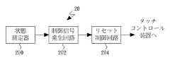
図4は本発明に係る好ましい実施形態のリセット装置の機能のブロック図である。リセット装置20は主に状態測定器200、制御信号発生回路202及びリセット制御回路204で構成される。状態測定器200はフレーム26のオン/オフ状態(例えば図3のフレームスイッチSWmのオン/オフの測定)の測定に用いられ、オン状態信号やオフ状態信号等の対応する状態信号を発生させる。制御信号発生回路202は状態信号に基き対応する制御信号を発生させる。これは例えば、制御信号発生回路202がオン/オフ状態信号の受信時に、対応する制御信号を発生させる事である。本実施形態の制御信号発生回路202はオン状態とオフ状態にそれぞれに合わせた制御信号を発生させるが、然しながら、他の実施形態では、例えばオフ状態時のみに制御信号を発生させる等、一種類の制御信号を発生させるのみでも良い。続いて、リセット制御回路204は、例えばタッチコントローラー220に対するリセット等、制御信号に基きタッチコントロール装置22のリセットを行う。これにより、タッチパネル221はフレーム26のオン/オフ状態変更後に、変更後の環境(例えば電界環境)下でタッチコントロール環境の再検索を行い、タッチコントロール精度の回復が得られる。 FIG. 4 is a block diagram of functions of the reset device according to the preferred embodiment of the present invention. The
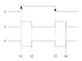
図5Aはリセット装置の機能のブロック図の例示であり、図5Bはリセット装置の詳細な回路図の例示であり、図5Cは図5Aと図5Bの相関する信号の波形の概略図である。本実施形態では、状態測定器200はフレームスイッチSWmを測定する。フレーム26のオフ時には、スイッチSWmは閉鎖され、このため状態信号Sは低レベル(第一レベル)となり、フレーム26のオン時には、スイッチSWmは切断され、このため状態信号Sは高レベル(第二レベル)となる。これにより、フレーム26はオフからオンへ変わる時は、ポジティブエッジ(或いは立ち上がりエッジ)状態信号Sを発生させ、フレーム26がオンからオフへ変わる時は、ネガティブエッジ(或いは立ち下がりエッジ)状態信号Sを発生させる。 5A is an example of a block diagram of the function of the reset device, FIG. 5B is an example of a detailed circuit diagram of the reset device, and FIG. 5C is a schematic diagram of waveforms of the correlated signals of FIGS. 5A and 5B. In the present embodiment, the
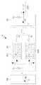
本実施形態では、制御信号発生回路202は少なくとも一つのエッジトリガ型フリップフロップ・ワンショット(one-shot)マルチバイブレータ(別称は単安定(monostable)マルチバイブレータ)を含み、図5Aにはポジティブエッジトリガ型フリップフロップ・ワンショットマルチバイブレータ202A及びネガティブエッジトリガ型フリップフロップ・ワンショットマルチバイブレータ202Bを図示する。本実施形態では(但しこれに限られないが)HITACHI型番号HD74HC123Aのデュアル・リトリガブル単安定マルチバイブレータ(Dual Retriggerable Monostable Multivibrators)を使用してポジティブエッジトリガ型フリップフロップ・ワンショットマルチバイブレータ202Aとネガティブエッジトリガ型フリップフロップ・ワンショットマルチバイブレータ202Bを実施している。ポジティブエッジトリガ型フリップフロップ・ワンショットマルチバイブレータ202Aが発生させるワンショット信号(即ち、制御信号C)のパルス幅は抵抗器R1及びキャパシタC1により決定され、ネガティブエッジトリガ型フリップフロップ・ワンショットマルチバイブレータ202Bが発生させるワンショット信号のパルス幅は抵抗器R2及びキャパシタC2により決定される。このほか、キャパシタC3とキャパシタC4は電源(+5V)のフィルターキャパシタである。このため、ポジティブエッジトリガ型フリップフロップ・ワンショットマルチバイブレータ202Aの入力(1B)がポジティブエッジトリガを受けた時、その出力(1Q)はワンショット信号を発生させ、そのパルス幅はR1*C1となり、ネガティブエッジトリガ型フリップフロップ・ワンショットマルチバイブレータ202Bの入力()がネガティブエッジトリガを受けた時、その出力(2Q)はワンショット信号を発生させ、そのパルス幅はR2*C2となる。図5Bに図示する回路の、ダイオードD1、ダイオードD2はポジティブエッジトリガ型フリップフロップ・ワンショットマルチバイブレータ202Aの出力とネガティブエッジトリガ型フリップフロップ・ワンショットマルチバイブレータ202Bの出力(1Q/2Q)にそれぞれ連結され、ロジック或いは(OR)機能回路を形成し、ポジティブエッジトリガ型フリップフロップ・ワンショットマルチバイブレータ202Aの出力、或いはネガティブエッジトリガ型フリップフロップ・ワンショットマルチバイブレータ202Bの出力を通過させ、各出力(1Q/2Q)間の干渉を防止する。このほか、制御信号発生回路202は抵抗器R5と抵抗器R6を使用して組成された分圧器であり、状態信号Sを適当な電圧レベル或いはプリセット電圧レベルに電圧固定(clamp)させる。 In this embodiment, the control
本実施形態では、リセット制御回路204は制御信号Cに制御され、その出力はタッチコントローラー220の電源入力端に連結される電源スイッチSWpを含む。制御信号Cのアクティブ(例えば、高レベルパルス)時、電源スイッチSWpは閉鎖され、出力は接地され、制御信号Cが非アクティブ(例えば低レベル)時、電源スイッチSWpは切断され、これにより電源Vccを出力する。言い換えれば、フレーム26がオン或いはオフになる時、制御信号Cはアクティブ(例えば、ワンショット信号の発生)に変わり、タッチコントロール装置22を接地(即ち電源切断)させる。一定の時間(例えば、ワンショット信号のパルス幅)を経過した後、制御信号Cは非アクティブに変わり、タッチコントロール装置22は電源Vccを受け、リセットを行い、これによりタッチコントロール装置22は変更後の環境(例えば電界環境)下でタッチコントロール環境の再検索を行う。本発明のリセットの実施方式はタッチコントローラー220の電源供給と切断の制御、、或いはタッチパネル221の電源の制御、更にはタッチコントロール装置22全体の電源の制御でも良い。他の実施形態では、リセット制御回路204の出力はタッチコントローラー220のリセット入力端に連結され、これを制御し、言い換えれば、この実施形態のタッチコントローラー220の電源は切断されていない情況下でリセットを行う。 In the present embodiment, the
図5Bに図示する回路のリセット制御回路204は、トランジスタQ1と抵抗器R3、抵抗器R4、抵抗器R7及びキャパシタC5で組成されるインバーターバッファを含む。トランジスタQ1のエミッタ接地は、コレクタを出力端とし抵抗器R7を経由し電源(+5V)に連結され、ベースを入力端として連結され制御信号Cを受信する。制御信号Cがアクティブ(例えば、高レベルパルス)時、トランジスタQ1は導通され出力Pを接地させ、制御信号Cが非アクティブ(例えば、低レベル)時、トランジスタQ1は切断され、そのため出力Pは抵抗器R7を経由し電源(+5V)となるまで高められる。 The
図5Cに図示する上述のシステム或いは回路の、フレーム26が時間t1に於いてオフからオンへ変わると、状態測定器200(例えば、機械スイッチSWm)はポジティブエッジ状態信号Sを出力させ、これがポジティブエッジトリガ型フリップフロップ・ワンショットマルチバイブレータ202Aを触発させアクティブパルス制御信号Cを発生させ、リセット制御回路204(例えば、インバーターバッファ)の出力Pを接地させ、タッチコントロール装置22の電源を切断させる。制御信号Cのパルスが時間t2で終結する時、リセット制御回路204は電源(+5V)をタッチコントロール装置22へ出力させ、リセットを行わせる。 When the
フレーム26が時間t3に於いてオンからオフへ変わると、状態測定器200はネガティブエッジ状態信号Sを出力させ、これがネガティブエッジトリガ型フリップフロップ・ワンショットマルチバイブレータ202Bを触発させアクティブパルス制御信号Cを発生させ、リセット制御回路204の出力を接地させ、タッチコントロール装置22の電源を切断させる。制御信号Cのパルスが時間t4で終結する時、リセット制御回路204の出力Pは電源(+5V)をタッチコントロール装置22へ出力させ、リセットを行わせる。上述の操作により、タッチコントロール装置22はフレーム26のオン/オフ状態の変更後にリセットを行い、変更後の環境(例えば電界環境)下でタッチコントロール環境の再検索を行い、タッチコントロール精度を回復させる。 When the
上述の実施形態は本発明の技術思想及び特徴を説明するためのものにすぎず、当該技術分野を熟知する者に本発明の内容を理解させると共にこれをもって実施させることを目的とし、本発明の特許請求の範囲を限定するものではない。従って、本発明の精神を逸脱せずに行う各種の同様の効果をもつ改良又は変更は、後述の請求項に含まれるものとする。 The above-described embodiments are merely for explaining the technical idea and features of the present invention, and are intended to allow those skilled in the art to understand the contents of the present invention and to carry out the same with the present invention. It is not intended to limit the scope of the claims. Accordingly, improvements or modifications having various similar effects made without departing from the spirit of the present invention shall be included in the following claims.
10 金属フレーム
12 コンピュータ本体
14 タッチコントロール装置
140 タッチコントローラー
20 リセット装置
200 状態測定器
202 制御信号発生回路
202A ポジティブエッジトリガ型フリップフロップ・ワンショットマルチバイブレータ
202B ネガティブエッジトリガ型フリップフロップ・ワンショットマルチバイブレータ
204 リセット制御回路
22 タッチコントロール装置
220 タッチコントローラー
221 タッチパネル
142 タッチパネル
24 コンピュータ本体
26 フレーム
260 ヒンジ
S 状態信号
C 制御信号
P リセット制御回路の出力
SW スイッチ
SWm フレームスイッチ
SWp 電源スイッチ
R1 抵抗器
R2 抵抗器
R3 抵抗器
R4 抵抗器
R5 抵抗器
R6 抵抗器
C1 キャパシタ
C2 キャパシタ
C3 キャパシタ
C4 キャパシタ
C5 キャパシタ
Q1 トランジスタ
D1 ダイオード
D2 ダイオードDESCRIPTION OF
Claims (28)
Translated fromJapaneseフレームのオン/オフ状態を測定し、対応する状態信号を発生させ、前記フレーム内にタッチコントロール装置が設置される状態測定器と、
前記状態信号に対応する制御信号を発生させる制御信号発生回路と、
前記制御信号に基き前記タッチコントロール装置のリセットを行うリセット制御回路を含み、
前記タッチコントロール装置は前記フレームのオン/オフ状態の変更後にリセットを行い、変更後のタッチコントロール環境下でタッチコントロール環境の再検索を行い、タッチコントロール精度を回復させることを特徴とする、自動測定と回復を行うタッチコントロールシステムのリセット装置。A touch control system reset device that performs automatic measurement and recovery,
A state measuring device that measures the on / off state of the frame, generates a corresponding state signal, and a touch control device is installed in the frame;
A control signal generating circuit for generating a control signal corresponding to the state signal;
A reset control circuit for resetting the touch control device based on the control signal;
The touch control device performs a reset after changing the on / off state of the frame, performs a re-search of the touch control environment under the touch control environment after the change, and restores the touch control accuracy. Touch control system reset device that performs recovery.
オン/オフされるフレームと、
前記フレーム内に設置されるタッチコントロール装置と、
前記フレームのオン/オフ状態を測定し、対応する状態信号を発生させる状態測定器と、
前記状態信号に基き対応する制御信号を発生させる制御信号発生回路と、
前記制御信号に基き前記タッチコントロール装置のリセットを行うリセット制御回路を含み、
前記タッチコントロール装置は前記フレームのオン/オフ状態を変更後にリセットを行い、変更後のタッチコントロール環境下でタッチコントロール環境の再検索を行い、タッチコントロール精度を回復させることを特徴とする自動測定と回復を行うタッチコントロールシステム。A touch control system for automatic measurement and recovery,
Frames that are turned on and off,
A touch control device installed in the frame;
A state measuring device that measures the on / off state of the frame and generates a corresponding state signal;
A control signal generating circuit for generating a corresponding control signal based on the state signal;
A reset control circuit for resetting the touch control device based on the control signal;
The touch control device resets after changing the on / off state of the frame, performs a re-search of the touch control environment under the changed touch control environment, and recovers the touch control accuracy. Touch control system for recovery.
Applications Claiming Priority (3)
| Application Number | Priority Date | Filing Date | Title |
|---|---|---|---|
| CN201010110713.5 | 2010-01-29 | ||
| CN2010101107135ACN102141850B (en) | 2010-01-29 | 2010-01-29 | Automatic detection and reply touch system and resetting device thereof |
| PCT/CN2010/000337WO2011091555A1 (en) | 2010-01-29 | 2010-03-19 | Touch control system for automatic detection and recovery and resetting apparatus thereof |
Publications (2)
| Publication Number | Publication Date |
|---|---|
| JP2012507816Atrue JP2012507816A (en) | 2012-03-29 |
| JP5089813B2 JP5089813B2 (en) | 2012-12-05 |
Family
ID=44318600
Family Applications (1)
| Application Number | Title | Priority Date | Filing Date |
|---|---|---|---|
| JP2011551396AExpired - Fee RelatedJP5089813B2 (en) | 2010-01-29 | 2010-03-19 | Automatic measurement and recovery system |
Country Status (6)
| Country | Link |
|---|---|
| US (1) | US20110234531A1 (en) |
| EP (1) | EP2530559A4 (en) |
| JP (1) | JP5089813B2 (en) |
| KR (1) | KR101226584B1 (en) |
| CN (1) | CN102141850B (en) |
| WO (1) | WO2011091555A1 (en) |
Families Citing this family (9)
| Publication number | Priority date | Publication date | Assignee | Title |
|---|---|---|---|---|
| JP2013059986A (en)* | 2011-09-15 | 2013-04-04 | Konica Minolta Business Technologies Inc | Operation panel, method of controlling the same, and program for controlling the same |
| CN102314277B (en)* | 2011-09-30 | 2014-11-05 | 惠州Tcl移动通信有限公司 | Anti-static method of capacitive touch screen and corresponding capacitive touch screen |
| KR101407311B1 (en)* | 2012-10-31 | 2014-06-13 | 엘지디스플레이 주식회사 | Touch display panel and method for recovering ligt sensor module of the same |
| CN102968237B (en)* | 2012-11-29 | 2017-04-19 | 广东欧珀移动通信有限公司 | Method and device for processing capacitive touch screen |
| CN108279815B (en)* | 2013-11-08 | 2020-07-07 | 禾瑞亚科技股份有限公司 | Transmitter and its position detection and calculation method, touch processing device and system |
| KR101628286B1 (en)* | 2014-11-25 | 2016-06-08 | 주식회사대성엘텍 | Multi-media control system and method for operating the same |
| CN107291281B (en)* | 2016-03-31 | 2020-06-23 | 日本电气株式会社 | Induction detection method and device |
| TWI782569B (en)* | 2021-06-09 | 2022-11-01 | 大陸商北京集創北方科技股份有限公司 | Reset source monitoring circuit, touch chip and information processing device |
| TWI767773B (en)* | 2021-06-30 | 2022-06-11 | 緯穎科技服務股份有限公司 | Intrusion detection apparatus and method thereof |
Citations (5)
| Publication number | Priority date | Publication date | Assignee | Title |
|---|---|---|---|---|
| JP2004295278A (en)* | 2003-03-26 | 2004-10-21 | Digital Electronics Corp | Computer with touch screen |
| JP2005535004A (en)* | 2002-03-27 | 2005-11-17 | ネルコアー ピューリタン ベネット インコーポレイテッド | Infrared touch frame system |
| JP2006333318A (en)* | 2005-05-30 | 2006-12-07 | Kyocera Mita Corp | Reset circuit |
| US20080036742A1 (en)* | 2006-08-08 | 2008-02-14 | Carrier Corporation | Method for resetting configuration on a touchscreen interface |
| JP2008160786A (en)* | 2006-11-27 | 2008-07-10 | Fujitsu Ltd | Reset circuit and system with reset circuit |
Family Cites Families (44)
| Publication number | Priority date | Publication date | Assignee | Title |
|---|---|---|---|---|
| DE2460057B2 (en)* | 1974-12-19 | 1977-02-10 | Robert Bosch Gmbh, 7000 Stuttgart | SWITCH ARRANGEMENT WITH A STRIKE FIELD CAPACITOR |
| US4572966A (en)* | 1983-12-22 | 1986-02-25 | Rockwell International Corporation | Activity monitor, power-on clear circuit |
| US4564818A (en)* | 1984-08-24 | 1986-01-14 | Motorola Inc. | Transimpedance amplifier having an improved gain/bandwidth product |
| US4718119A (en)* | 1984-08-27 | 1988-01-05 | Motorola Inc. | AGC circuit including a precision voltage clamp and method |
| EP0626633B1 (en)* | 1993-05-28 | 2001-03-14 | Sun Microsystems, Inc. | Touch screen power control in a computer system |
| GB2286100A (en)* | 1994-01-19 | 1995-08-02 | Ibm | Touch-sensitive display apparatus |
| US5499184A (en)* | 1994-01-28 | 1996-03-12 | Compaq Computer Corp. | Power switch circuitry for electrically isolating the power switch from a power supply |
| JP2705631B2 (en)* | 1995-04-26 | 1998-01-28 | 日本電気株式会社 | Portable electronic devices |
| US5956020A (en)* | 1995-07-27 | 1999-09-21 | Microtouch Systems, Inc. | Touchscreen controller with pen and/or finger inputs |
| US6016140A (en)* | 1997-10-29 | 2000-01-18 | Nortel Networks Corporation | Automatic touch screen calibration |
| KR100348275B1 (en)* | 2000-07-28 | 2002-08-09 | 엘지전자 주식회사 | driving control circuit in organic electroluminescence |
| US6980184B1 (en)* | 2000-09-27 | 2005-12-27 | Alien Technology Corporation | Display devices and integrated circuits |
| US6583676B2 (en)* | 2001-06-20 | 2003-06-24 | Apple Computer, Inc. | Proximity/touch detector and calibration circuit |
| CN1169036C (en)* | 2002-03-28 | 2004-09-29 | 威盛电子股份有限公司 | Automatic reset signal generating device capable of being integrated in chip set |
| US20040204000A1 (en)* | 2002-05-30 | 2004-10-14 | Aaron Dietrich | Mobile communication device including an array sensor |
| US7236161B2 (en)* | 2003-03-21 | 2007-06-26 | 3M Innovative Properties Company | Remote touch simulation systems and methods |
| JP2005222522A (en)* | 2004-01-07 | 2005-08-18 | Sony Corp | Electronic apparatus |
| CN2731531Y (en)* | 2004-08-10 | 2005-10-05 | 鸿富锦精密工业(深圳)有限公司 | Coverplate lock means of computer |
| US20070074913A1 (en)* | 2005-10-05 | 2007-04-05 | Geaghan Bernard O | Capacitive touch sensor with independently adjustable sense channels |
| KR100640822B1 (en)* | 2005-11-22 | 2006-11-02 | 엘지전자 주식회사 | Glass touch key input device |
| US7388486B2 (en)* | 2006-01-05 | 2008-06-17 | Honeywell International Inc. | Method and system to detect tampering using light detector |
| JP4657174B2 (en)* | 2006-08-25 | 2011-03-23 | 京セラ株式会社 | Display device |
| US9280238B2 (en)* | 2006-08-30 | 2016-03-08 | Intel Corporation | Electrical touch screen sensor |
| JP4578451B2 (en)* | 2006-09-15 | 2010-11-10 | 京セラ株式会社 | Electronics |
| US20080100586A1 (en)* | 2006-10-26 | 2008-05-01 | Deere & Company | Method and system for calibrating a touch screen |
| US8508523B2 (en)* | 2007-04-23 | 2013-08-13 | Ricoh Company, Ltd. | Information display device, information displaying method, and computer program product |
| CN101802757B (en)* | 2007-05-08 | 2017-07-21 | 瑟克公司 | Intrusion Detection Using Capacitive Sensitive Touchpads |
| EP2160673A1 (en)* | 2007-06-25 | 2010-03-10 | Nokia Corporation | Improvements in or relating to user interfaces and associated apparatus and methods |
| US8595514B2 (en)* | 2008-01-22 | 2013-11-26 | Verifone, Inc. | Secure point of sale terminal |
| US8044943B2 (en)* | 2008-06-03 | 2011-10-25 | Himax Technologies Limited | Touch panel |
| KR101015884B1 (en)* | 2008-07-16 | 2011-02-23 | 삼성모바일디스플레이주식회사 | Touch panel driving circuit for removing current caused by finger heat and touch panel including the same |
| US8502801B2 (en)* | 2008-08-28 | 2013-08-06 | Stmicroelectronics Asia Pacific Pte Ltd. | Capacitive touch sensor system |
| KR100982282B1 (en)* | 2008-09-19 | 2010-09-15 | 주식회사 애트랩 | Sensor, sensor sensing method, and sensor filter |
| KR100975871B1 (en)* | 2008-10-17 | 2010-08-13 | 삼성모바일디스플레이주식회사 | An optical sensing circuit, a touch panel including the same, and a driving method of the optical sensing circuit |
| US8436816B2 (en)* | 2008-10-24 | 2013-05-07 | Apple Inc. | Disappearing button or slider |
| JP2010112931A (en)* | 2008-11-10 | 2010-05-20 | Toyota Motor Corp | Reset system, and mobile device, communication apparatus and method used in the system |
| CN101424855B (en)* | 2008-12-09 | 2010-06-02 | 友达光电股份有限公司 | display panel with multiple touch control function |
| US20100177057A1 (en)* | 2009-01-13 | 2010-07-15 | Qsi Corporation | System and method for detecting shocks to a force-based touch panel |
| TW201032109A (en)* | 2009-02-18 | 2010-09-01 | Novatek Microelectronics Corp | Method capable of timely calibrating a touch parameter and related apparatus and system |
| TWI401597B (en)* | 2009-02-25 | 2013-07-11 | Ite Tech Inc | Method and apparatus for drift compensation of capacitive touch panel |
| US8278948B2 (en)* | 2009-08-10 | 2012-10-02 | Apple Inc. | Mechanisms for detecting tampering of an electronic device |
| JP5548270B2 (en)* | 2009-08-21 | 2014-07-16 | アップル インコーポレイテッド | Capacitive sensing method and apparatus |
| US8624430B2 (en)* | 2009-11-19 | 2014-01-07 | General Electric Company | Standby power reduction |
| US8411066B2 (en)* | 2010-01-05 | 2013-04-02 | 3M Innovative Properties Company | High speed noise tolerant multi-touch touch device and controller therefor |
- 2010
- 2010-01-29CNCN2010101107135Apatent/CN102141850B/ennot_activeExpired - Fee Related
- 2010-03-19KRKR1020117005547Apatent/KR101226584B1/ennot_activeExpired - Fee Related
- 2010-03-19JPJP2011551396Apatent/JP5089813B2/ennot_activeExpired - Fee Related
- 2010-03-19WOPCT/CN2010/000337patent/WO2011091555A1/enactiveApplication Filing
- 2010-03-19EPEP10809218.0Apatent/EP2530559A4/ennot_activeWithdrawn
- 2010-09-26USUS12/890,665patent/US20110234531A1/ennot_activeAbandoned
Patent Citations (5)
| Publication number | Priority date | Publication date | Assignee | Title |
|---|---|---|---|---|
| JP2005535004A (en)* | 2002-03-27 | 2005-11-17 | ネルコアー ピューリタン ベネット インコーポレイテッド | Infrared touch frame system |
| JP2004295278A (en)* | 2003-03-26 | 2004-10-21 | Digital Electronics Corp | Computer with touch screen |
| JP2006333318A (en)* | 2005-05-30 | 2006-12-07 | Kyocera Mita Corp | Reset circuit |
| US20080036742A1 (en)* | 2006-08-08 | 2008-02-14 | Carrier Corporation | Method for resetting configuration on a touchscreen interface |
| JP2008160786A (en)* | 2006-11-27 | 2008-07-10 | Fujitsu Ltd | Reset circuit and system with reset circuit |
Also Published As
| Publication number | Publication date |
|---|---|
| CN102141850A (en) | 2011-08-03 |
| EP2530559A4 (en) | 2016-02-17 |
| EP2530559A1 (en) | 2012-12-05 |
| US20110234531A1 (en) | 2011-09-29 |
| CN102141850B (en) | 2013-05-08 |
| KR101226584B1 (en) | 2013-01-28 |
| JP5089813B2 (en) | 2012-12-05 |
| KR20110127112A (en) | 2011-11-24 |
| WO2011091555A1 (en) | 2011-08-04 |
Similar Documents
| Publication | Publication Date | Title |
|---|---|---|
| JP5089813B2 (en) | Automatic measurement and recovery system | |
| JP6669930B2 (en) | Systems, methods, and integrated circuits for detecting voltage drops | |
| TW201617780A (en) | Power trace port for tracing states of power domains | |
| Pavithran et al. | UVM based testbench architecture for logic sub-system verification | |
| US20150220672A1 (en) | Method and apparatus for modelling power consumption of integrated circuit | |
| IT201800005511A1 (en) | RESET CIRCUIT, CORRESPONDING DEVICE AND PROCEDURE | |
| US20140188424A1 (en) | Fan test device | |
| CN111079293B (en) | Jitter simulation analysis method containing dynamic power supply noise | |
| CN102368171B (en) | Automatic recovering system of touch screen controller | |
| RU2432601C2 (en) | Method of introducing determinism among multiple clock intervals | |
| JP2017126850A (en) | Communication interface circuit and semiconductor integrated circuit | |
| CN103929155A (en) | Pulse Width Stretching Circuit | |
| Nunez-Yanez et al. | Run-time power and performance scaling with CPU-FPGA hybrids | |
| US10127126B2 (en) | Rapid system debugging using finite state machines | |
| CN104460920A (en) | Switching circuit and computer device with the same | |
| CN107390029B (en) | Device for eliminating reverse electromotive force during inductive load DCR measurement | |
| CN205375228U (en) | Ageing quick -witted control by temperature change circuit | |
| CN109657383B (en) | Spice simulation method of time sequence path | |
| CN203287426U (en) | An overcurrent determining circuit | |
| CN102129496A (en) | Method and system for simulating power integrity of chip | |
| CN201681361U (en) | Automatic detecting and resetting touch control system and resetting device thereof | |
| CN101996143B (en) | Reset Circuits for Electronic Devices | |
| CN108241397B (en) | Circuit and method for compensating leakage of multiplexing circuit | |
| CN106253768A (en) | Brushless DC motor control system based on DSP | |
| CN118033381B (en) | Chip load detection method and circuit |
Legal Events
| Date | Code | Title | Description |
|---|---|---|---|
| A521 | Request for written amendment filed | Free format text:JAPANESE INTERMEDIATE CODE: A523 Effective date:20110309 | |
| A621 | Written request for application examination | Free format text:JAPANESE INTERMEDIATE CODE: A621 Effective date:20110309 | |
| TRDD | Decision of grant or rejection written | ||
| A01 | Written decision to grant a patent or to grant a registration (utility model) | Free format text:JAPANESE INTERMEDIATE CODE: A01 Effective date:20120904 | |
| A01 | Written decision to grant a patent or to grant a registration (utility model) | Free format text:JAPANESE INTERMEDIATE CODE: A01 | |
| A61 | First payment of annual fees (during grant procedure) | Free format text:JAPANESE INTERMEDIATE CODE: A61 Effective date:20120911 | |
| FPAY | Renewal fee payment (event date is renewal date of database) | Free format text:PAYMENT UNTIL: 20150921 Year of fee payment:3 | |
| R150 | Certificate of patent or registration of utility model | Free format text:JAPANESE INTERMEDIATE CODE: R150 | |
| R250 | Receipt of annual fees | Free format text:JAPANESE INTERMEDIATE CODE: R250 | |
| R250 | Receipt of annual fees | Free format text:JAPANESE INTERMEDIATE CODE: R250 | |
| LAPS | Cancellation because of no payment of annual fees |