JP2012505057A - Low profile surgical access device with anchor mechanism - Google Patents
Low profile surgical access device with anchor mechanismDownload PDFInfo
- Publication number
- JP2012505057A JP2012505057AJP2011531240AJP2011531240AJP2012505057AJP 2012505057 AJP2012505057 AJP 2012505057AJP 2011531240 AJP2011531240 AJP 2011531240AJP 2011531240 AJP2011531240 AJP 2011531240AJP 2012505057 AJP2012505057 AJP 2012505057A
- Authority
- JP
- Japan
- Prior art keywords
- access device
- housing
- surgical access
- pressurized fluid
- plenum chamber
- Prior art date
- Legal status (The legal status is an assumption and is not a legal conclusion. Google has not performed a legal analysis and makes no representation as to the accuracy of the status listed.)
- Granted
Links
Images


Classifications
- A—HUMAN NECESSITIES
- A61—MEDICAL OR VETERINARY SCIENCE; HYGIENE
- A61B—DIAGNOSIS; SURGERY; IDENTIFICATION
- A61B17/00—Surgical instruments, devices or methods
- A61B17/34—Trocars; Puncturing needles
- A61B17/3417—Details of tips or shafts, e.g. grooves, expandable, bendable; Multiple coaxial sliding cannulas, e.g. for dilating
- A—HUMAN NECESSITIES
- A61—MEDICAL OR VETERINARY SCIENCE; HYGIENE
- A61B—DIAGNOSIS; SURGERY; IDENTIFICATION
- A61B17/00—Surgical instruments, devices or methods
- A61B17/34—Trocars; Puncturing needles
- A—HUMAN NECESSITIES
- A61—MEDICAL OR VETERINARY SCIENCE; HYGIENE
- A61B—DIAGNOSIS; SURGERY; IDENTIFICATION
- A61B1/00—Instruments for performing medical examinations of the interior of cavities or tubes of the body by visual or photographical inspection, e.g. endoscopes; Illuminating arrangements therefor
- A61B1/32—Devices for opening or enlarging the visual field, e.g. of a tube of the body
- A—HUMAN NECESSITIES
- A61—MEDICAL OR VETERINARY SCIENCE; HYGIENE
- A61B—DIAGNOSIS; SURGERY; IDENTIFICATION
- A61B17/00—Surgical instruments, devices or methods
- A61B17/02—Surgical instruments, devices or methods for holding wounds open, e.g. retractors; Tractors
- A—HUMAN NECESSITIES
- A61—MEDICAL OR VETERINARY SCIENCE; HYGIENE
- A61B—DIAGNOSIS; SURGERY; IDENTIFICATION
- A61B90/00—Instruments, implements or accessories specially adapted for surgery or diagnosis and not covered by any of the groups A61B1/00 - A61B50/00, e.g. for luxation treatment or for protecting wound edges
- A—HUMAN NECESSITIES
- A61—MEDICAL OR VETERINARY SCIENCE; HYGIENE
- A61M—DEVICES FOR INTRODUCING MEDIA INTO, OR ONTO, THE BODY; DEVICES FOR TRANSDUCING BODY MEDIA OR FOR TAKING MEDIA FROM THE BODY; DEVICES FOR PRODUCING OR ENDING SLEEP OR STUPOR
- A61M29/00—Dilators with or without means for introducing media, e.g. remedies
- A—HUMAN NECESSITIES
- A61—MEDICAL OR VETERINARY SCIENCE; HYGIENE
- A61M—DEVICES FOR INTRODUCING MEDIA INTO, OR ONTO, THE BODY; DEVICES FOR TRANSDUCING BODY MEDIA OR FOR TAKING MEDIA FROM THE BODY; DEVICES FOR PRODUCING OR ENDING SLEEP OR STUPOR
- A61M39/00—Tubes, tube connectors, tube couplings, valves, access sites or the like, specially adapted for medical use
- A61M39/02—Access sites
- A61M39/0247—Semi-permanent or permanent transcutaneous or percutaneous access sites to the inside of the body
- A—HUMAN NECESSITIES
- A61—MEDICAL OR VETERINARY SCIENCE; HYGIENE
- A61M—DEVICES FOR INTRODUCING MEDIA INTO, OR ONTO, THE BODY; DEVICES FOR TRANSDUCING BODY MEDIA OR FOR TAKING MEDIA FROM THE BODY; DEVICES FOR PRODUCING OR ENDING SLEEP OR STUPOR
- A61M39/00—Tubes, tube connectors, tube couplings, valves, access sites or the like, specially adapted for medical use
- A61M39/02—Access sites
- A61M39/04—Access sites having pierceable self-sealing members
- G—PHYSICS
- G02—OPTICS
- G02B—OPTICAL ELEMENTS, SYSTEMS OR APPARATUS
- G02B23/00—Telescopes, e.g. binoculars; Periscopes; Instruments for viewing the inside of hollow bodies; Viewfinders; Optical aiming or sighting devices
- G02B23/24—Instruments or systems for viewing the inside of hollow bodies, e.g. fibrescopes
- A—HUMAN NECESSITIES
- A61—MEDICAL OR VETERINARY SCIENCE; HYGIENE
- A61B—DIAGNOSIS; SURGERY; IDENTIFICATION
- A61B17/00—Surgical instruments, devices or methods
- A61B17/34—Trocars; Puncturing needles
- A61B17/3417—Details of tips or shafts, e.g. grooves, expandable, bendable; Multiple coaxial sliding cannulas, e.g. for dilating
- A61B17/3421—Cannulas
- A61B17/3423—Access ports, e.g. toroid shape introducers for instruments or hands
- A—HUMAN NECESSITIES
- A61—MEDICAL OR VETERINARY SCIENCE; HYGIENE
- A61B—DIAGNOSIS; SURGERY; IDENTIFICATION
- A61B17/00—Surgical instruments, devices or methods
- A61B17/34—Trocars; Puncturing needles
- A61B17/3417—Details of tips or shafts, e.g. grooves, expandable, bendable; Multiple coaxial sliding cannulas, e.g. for dilating
- A61B17/3421—Cannulas
- A61B17/3431—Cannulas being collapsible, e.g. made of thin flexible material
- A—HUMAN NECESSITIES
- A61—MEDICAL OR VETERINARY SCIENCE; HYGIENE
- A61B—DIAGNOSIS; SURGERY; IDENTIFICATION
- A61B17/00—Surgical instruments, devices or methods
- A61B17/34—Trocars; Puncturing needles
- A61B17/3474—Insufflating needles, e.g. Veress needles
- A—HUMAN NECESSITIES
- A61—MEDICAL OR VETERINARY SCIENCE; HYGIENE
- A61B—DIAGNOSIS; SURGERY; IDENTIFICATION
- A61B17/00—Surgical instruments, devices or methods
- A61B17/34—Trocars; Puncturing needles
- A61B17/3498—Valves therefor, e.g. flapper valves, slide valves
- A—HUMAN NECESSITIES
- A61—MEDICAL OR VETERINARY SCIENCE; HYGIENE
- A61B—DIAGNOSIS; SURGERY; IDENTIFICATION
- A61B17/00—Surgical instruments, devices or methods
- A61B17/34—Trocars; Puncturing needles
- A61B17/3417—Details of tips or shafts, e.g. grooves, expandable, bendable; Multiple coaxial sliding cannulas, e.g. for dilating
- A61B17/3421—Cannulas
- A61B2017/3445—Cannulas used as instrument channel for multiple instruments
- A—HUMAN NECESSITIES
- A61—MEDICAL OR VETERINARY SCIENCE; HYGIENE
- A61B—DIAGNOSIS; SURGERY; IDENTIFICATION
- A61B17/00—Surgical instruments, devices or methods
- A61B17/34—Trocars; Puncturing needles
- A61B2017/348—Means for supporting the trocar against the body or retaining the trocar inside the body
- A61B2017/3482—Means for supporting the trocar against the body or retaining the trocar inside the body inside
- A61B2017/3484—Anchoring means, e.g. spreading-out umbrella-like structure
- A—HUMAN NECESSITIES
- A61—MEDICAL OR VETERINARY SCIENCE; HYGIENE
- A61M—DEVICES FOR INTRODUCING MEDIA INTO, OR ONTO, THE BODY; DEVICES FOR TRANSDUCING BODY MEDIA OR FOR TAKING MEDIA FROM THE BODY; DEVICES FOR PRODUCING OR ENDING SLEEP OR STUPOR
- A61M39/00—Tubes, tube connectors, tube couplings, valves, access sites or the like, specially adapted for medical use
- A61M39/02—Access sites
- A61M39/0247—Semi-permanent or permanent transcutaneous or percutaneous access sites to the inside of the body
- A61M2039/0261—Means for anchoring port to the body, or ports having a special shape or being made of a specific material to allow easy implantation/integration in the body
- A—HUMAN NECESSITIES
- A61—MEDICAL OR VETERINARY SCIENCE; HYGIENE
- A61M—DEVICES FOR INTRODUCING MEDIA INTO, OR ONTO, THE BODY; DEVICES FOR TRANSDUCING BODY MEDIA OR FOR TAKING MEDIA FROM THE BODY; DEVICES FOR PRODUCING OR ENDING SLEEP OR STUPOR
- A61M39/00—Tubes, tube connectors, tube couplings, valves, access sites or the like, specially adapted for medical use
- A61M39/02—Access sites
- A61M39/0247—Semi-permanent or permanent transcutaneous or percutaneous access sites to the inside of the body
- A61M2039/0264—Semi-permanent or permanent transcutaneous or percutaneous access sites to the inside of the body with multiple inlets or multiple outlets
- A—HUMAN NECESSITIES
- A61—MEDICAL OR VETERINARY SCIENCE; HYGIENE
- A61M—DEVICES FOR INTRODUCING MEDIA INTO, OR ONTO, THE BODY; DEVICES FOR TRANSDUCING BODY MEDIA OR FOR TAKING MEDIA FROM THE BODY; DEVICES FOR PRODUCING OR ENDING SLEEP OR STUPOR
- A61M39/00—Tubes, tube connectors, tube couplings, valves, access sites or the like, specially adapted for medical use
- A61M39/02—Access sites
- A61M39/0247—Semi-permanent or permanent transcutaneous or percutaneous access sites to the inside of the body
- A61M2039/0276—Semi-permanent or permanent transcutaneous or percutaneous access sites to the inside of the body for introducing or removing fluids into or out of the body
- A—HUMAN NECESSITIES
- A61—MEDICAL OR VETERINARY SCIENCE; HYGIENE
- A61M—DEVICES FOR INTRODUCING MEDIA INTO, OR ONTO, THE BODY; DEVICES FOR TRANSDUCING BODY MEDIA OR FOR TAKING MEDIA FROM THE BODY; DEVICES FOR PRODUCING OR ENDING SLEEP OR STUPOR
- A61M39/00—Tubes, tube connectors, tube couplings, valves, access sites or the like, specially adapted for medical use
- A61M39/02—Access sites
- A61M39/0247—Semi-permanent or permanent transcutaneous or percutaneous access sites to the inside of the body
- A61M2039/0279—Semi-permanent or permanent transcutaneous or percutaneous access sites to the inside of the body for introducing medical instruments into the body, e.g. endoscope, surgical tools
- A—HUMAN NECESSITIES
- A61—MEDICAL OR VETERINARY SCIENCE; HYGIENE
- A61M—DEVICES FOR INTRODUCING MEDIA INTO, OR ONTO, THE BODY; DEVICES FOR TRANSDUCING BODY MEDIA OR FOR TAKING MEDIA FROM THE BODY; DEVICES FOR PRODUCING OR ENDING SLEEP OR STUPOR
- A61M39/00—Tubes, tube connectors, tube couplings, valves, access sites or the like, specially adapted for medical use
- A61M39/02—Access sites
- A61M39/04—Access sites having pierceable self-sealing members
- A61M39/045—Access sites having pierceable self-sealing members pre-slit to be pierced by blunt instrument
Landscapes
- Health & Medical Sciences (AREA)
- Life Sciences & Earth Sciences (AREA)
- Surgery (AREA)
- Heart & Thoracic Surgery (AREA)
- Veterinary Medicine (AREA)
- General Health & Medical Sciences (AREA)
- Engineering & Computer Science (AREA)
- Biomedical Technology (AREA)
- Public Health (AREA)
- Animal Behavior & Ethology (AREA)
- Molecular Biology (AREA)
- Nuclear Medicine, Radiotherapy & Molecular Imaging (AREA)
- Medical Informatics (AREA)
- Pathology (AREA)
- Physics & Mathematics (AREA)
- Anesthesiology (AREA)
- Hematology (AREA)
- Biophysics (AREA)
- Pulmonology (AREA)
- Optics & Photonics (AREA)
- Gastroenterology & Hepatology (AREA)
- General Physics & Mathematics (AREA)
- Astronomy & Astrophysics (AREA)
- Oral & Maxillofacial Surgery (AREA)
- Radiology & Medical Imaging (AREA)
- Surgical Instruments (AREA)
Abstract
Translated fromJapaneseDescription
Translated fromJapanese関連出願の相互参照
本願は、2008年10月10日に出願された米国仮特許出願第61/104,475号明細書に対する優先権の利益を主張する。本願はまた、米国特許第7,182,752号明細書、米国特許第7,338,473号明細書、及び米国特許第7,285,112号明細書、米国特許出願公開第2007/0088275号明細書及び国際公開第2008/077080号パンフレットとして公開されたPCT出願PCT/US07/88017号にも関する。前述の特許及び出願の各々は、全体として参照により本明細書に援用される。This application claims the benefit of priority over US Provisional Patent Application No. 61 / 104,475, filed Oct. 10, 2008. This application also includes U.S. Patent No. 7,182,752, U.S. Patent No. 7,338,473, and U.S. Patent No. 7,285,112, U.S. Patent Application Publication No. 2007/0088275. It also relates to the specification and PCT application PCT / US07 / 88017 published as WO 2008/077700 pamphlet. Each of the foregoing patents and applications is hereby incorporated by reference in its entirety.
本発明は、最小侵襲手術手技を実施するための手術用アクセス装置に関する。特に、本発明は、患者の腹壁を通じて設けられた切開等の切開に固定的に留置するために特に適合された手術用アクセス装置に関する。本発明はまた、腹部吹送下での腹膜圧の損失を抑制するための非機械式圧力バリアを含む、かかる手術用アクセス装置にも関する。 The present invention relates to a surgical access device for performing minimally invasive surgical procedures. In particular, the invention relates to a surgical access device that is particularly adapted for placement in a fixed incision, such as an incision made through a patient's abdominal wall. The present invention also relates to such a surgical access device including a non-mechanical pressure barrier for suppressing loss of peritoneal pressure under abdominal insufflation.
当該技術分野では、腹腔などの手術部位にアクセスするための様々なアクセス装置が公知である。典型的には、過度の外傷を引き起こすことなく、確実にかかるアクセス装置を腹壁に固定的に装着されたままとすることが、第一の目標である。本発明は、このような問題に対して様々な解決策を提供する。 Various access devices for accessing a surgical site such as the abdominal cavity are known in the art. Typically, the primary goal is to ensure that such an access device remains securely attached to the abdominal wall without causing undue trauma. The present invention provides various solutions to such problems.
本発明の目的及び利点は以下の説明に示され、且つその記載から明らかとなるであろう。 Objects and advantages of the present invention are set forth in the following description and will be apparent from the description.
これらの、及び他の利点を実現するため、並びに具体化されるとおりの、本発明の目的に従えば、本発明は、一態様において、ハウジングの近位端部分及び遠位端部分と、ハウジングの遠位端から遠位に延在するアクセス・チューブとを有する手術用アクセス装置を含む。アクセス・チューブは、患者の腹壁に形成された切開を通じて少なくとも部分的に延在するように適合及び構成され、且つ双曲線形の断面形状と、切開からの脱落を抑制する直径が拡大した遠位部分とを有する。プレナム・チャンバが、ハウジング内に少なくとも1つのノズルと流体連通して画定されてもよく、且つ加圧流体をプレナム・チャンバからアクセス・チューブの中心穴へと軸方向に誘導することにより、そこを通じて挿入された手術器具の周りに一定のガス・シールを設け、同時にそこを通じた体腔からの加圧流体の損失を抑制するように構成されてもよい。プレナム・チャンバは、加圧流体を受け取り、その加圧流体を少なくとも1つのノズルに導くように適合及び構成されてもよい。プレナム・チャンバは、加圧流体の供給源と連通するための入口ポートを有してもよい。圧力検知チャンバがハウジング内に画定され、且つ患者の腹腔と流体連通して腹圧の検知を促進するように適合及び構成されてもよい。圧力検知チャンバは、接続されたシステムの圧力センサと連通するための出口ポートを含んでもよい。検知チャンバは、手術用アクセス装置のアクセス・チューブに画定された検知チャネルと流体連通していてもよい。 In order to achieve these and other advantages, and in accordance with the objectives of the present invention as embodied, the present invention, in one aspect, includes a housing proximal end portion and a distal end portion, and a housing. A surgical access device having an access tube extending distally from the distal end thereof. The access tube is adapted and configured to extend at least partially through an incision formed in the patient's abdominal wall, and has a hyperbolic cross-sectional shape and a distal portion with an increased diameter that prevents dropout And have. A plenum chamber may be defined in fluid communication with the at least one nozzle in the housing, and through which the pressurized fluid is guided axially from the plenum chamber to the central hole of the access tube. A gas seal may be provided around the inserted surgical instrument and at the same time configured to suppress loss of pressurized fluid from the body cavity therethrough. The plenum chamber may be adapted and configured to receive pressurized fluid and direct the pressurized fluid to at least one nozzle. The plenum chamber may have an inlet port for communicating with a source of pressurized fluid. A pressure sensing chamber may be defined in the housing and adapted and configured to be in fluid communication with the patient's abdominal cavity to facilitate detection of abdominal pressure. The pressure sensing chamber may include an outlet port for communicating with a pressure sensor of the connected system. The sensing chamber may be in fluid communication with a sensing channel defined in the access tube of the surgical access device.
ノズルは、近位ハウジング内に配置されたノズル・インサートの外周と、近位ハウジング内に配置された実質的に環状のインサートの内周との間に形成された間隙によって画定されてもよい。 The nozzle may be defined by a gap formed between an outer periphery of a nozzle insert disposed within the proximal housing and an inner periphery of a substantially annular insert disposed within the proximal housing.
本発明の別の態様に従えば、近位端部分と遠位端部分とを有する近位ハウジングを含む手術用アクセス装置が提供され、ハウジングの遠位端部分は、可撓性開創器の近位部分を係合するように構成及び適合される。近位ハウジングには、そこに画定されたプレナム・チャンバが提供されてもよく、プレナム・チャンバは少なくとも1つのノズルと流体連通している。ノズルは、好ましくは、加圧流体をプレナム・チャンバから手術用アクセス装置の中心穴へと軸方向に誘導することにより、そこを通じて挿入された手術器具の周りに一定のガス・シールを設け、同時にそこを通じた体腔からの加圧流体の損失を抑制するように構成される。プレナム・チャンバは、加圧流体を受け取り、その加圧流体を少なくとも1つのノズルに導くように適合及び構成されてもよい。 In accordance with another aspect of the present invention, a surgical access device is provided that includes a proximal housing having a proximal end portion and a distal end portion, the distal end portion of the housing being proximate to the flexible retractor. Configured and adapted to engage the position portion. The proximal housing may be provided with a plenum chamber defined therein, the plenum chamber being in fluid communication with at least one nozzle. The nozzle preferably provides a constant gas seal around the surgical instrument inserted therethrough by axially directing pressurized fluid from the plenum chamber to the central hole of the surgical access device, while at the same time It is configured to suppress loss of pressurized fluid from the body cavity therethrough. The plenum chamber may be adapted and configured to receive pressurized fluid and direct the pressurized fluid to at least one nozzle.
前述の一般的な説明及び以下の詳細な説明は、双方とも例示であり、本発明の非限定的な説明の提供を意図していることが理解されるべきである。 It should be understood that both the foregoing general description and the following detailed description are exemplary and are intended to provide a non-limiting description of the invention.
本明細書に援用され、且つその一部を構成する添付の図面は、本発明の方法及びシステムを例示し、そのさらなる理解を提供することを意図している。その説明と共に、図面が本発明の原理を説明するために供される。 The accompanying drawings, which are incorporated in and constitute a part of this specification, illustrate the method and system of the present invention and are intended to provide a further understanding thereof. Together with the description, the drawings serve to explain the principles of the invention.
ここで、本明細書における本発明の好ましい実施形態を詳細に参照し、その例が添付の図面に示される。本発明の関連する方法は、装置の詳細な説明と併せて記載される。 Reference will now be made in detail to the presently preferred embodiments of the invention, examples of which are illustrated in the accompanying drawings. Related methods of the present invention are described in conjunction with a detailed description of the apparatus.
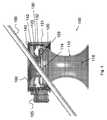
本発明に従えば、図1に示されるとおり、手術用アクセス装置100が提供され、これは有利には、比較的ロー・プロファイルであり、より一般的な手術用アクセス装置と比べて、そこを通じて挿入される手術器具190の動作上の制限を小さくすることができる。アクセス装置100は、ハウジング120と、ハウジング120の遠位端から遠位に延在する柔軟なアクセス・チューブ110とを含む。アクセス・チューブ110は、患者の腹壁に形成された切開を通じて少なくとも部分的に延在するように適合及び構成される。示される実施形態において、アクセス・チューブ110は双曲線形の断面形状を有する。アクセス・チューブ110の直径が拡大した遠位部分が、患者に形成された切開からのアクセス装置100の脱落を抑制する。本発明に従えば、アクセス・チューブ110の長さは、患者の腹壁を通じて腹膜空間の中へと完全に延在するのに十分な長さであってもよい。 In accordance with the present invention, there is provided a
本発明に従えば、アクセス装置100は吹送機能をさらに含んでもよく、そこを通じて挿入される器具の周りに流体シール若しくは気圧バリアを形成するように適合及び構成されてもよく、及び/又は吹送ガスの再循環を促進するように適合されてもよい。かかる機能の詳細が、米国特許第7,182,752号明細書、米国特許第7,285,112号明細書、米国特許第7,338,473号明細書、米国特許出願公開第2007/0088275号明細書及びPCT国際公開第2008/077080号パンフレットに記載されており、これらの文献は全体として参照により本明細書に援用される。 In accordance with the present invention, the
図1に示されるとおり、例えば、手術用アクセス装置100は、ハウジング120内に画定された加圧流体プレナム123を含んでもよい。示される実施形態において、プレナム123は、ハウジング120と下側インサート130と上側インサート140との間に画定される。プレナム123は少なくとも1つのノズル128と流体連通し、加圧流体をプレナム123からアクセス・チューブ110の中心ルーメン118へと実質的に軸方向に誘導することにより、そこを通じて挿入された手術器具の周りに、及び/又は、例えば、そこを通じて器具が挿入されていないときにはルーメン118にわたって、一定のガス・シールを設けるように構成される。 As shown in FIG. 1, for example, the
同様に、示されるとおり、アクセス装置100には、ハウジング120と下側インサート130との間に再循環チャンバ121が画定されてもよい。弾性Oリングなどの1つ又は複数の封止要素が、第1のインサート130及び第2のインサート140の各々にそれぞれ形成される座部132、142に提供されてもよい。ルーメン118と再循環チャンバ121との間に、ガスが再循環チャンバ121に入ることを可能にする1つ又は複数の開口114が提供されてもよい。 Similarly, as shown, the
1つ又は複数の追加のチャンバ又は他の流体導管がさらに提供されてもよく、それにより圧力検知装置及び/又は手術用インサフレーターと作業部位との間の流体連通が促進される。流体導管は、アクセス・チューブ110の内側又は外側の表面の壁内に、又は表面上に形成されてもよい。或いは、それが所望であれば、別個のチューブがかかる目的でルーメン118に挿通されてもよい。さらなる代替的実施形態において、及び例えば図2〜図6の実施形態に示されるとおり、圧力検知及び/又は吹送穴424が、単純にルーメン418の上側部分と流体連通していてもよい。 One or more additional chambers or other fluid conduits may further be provided to facilitate fluid communication between the pressure sensing device and / or the surgical insufflator and the work site. The fluid conduit may be formed in or on the wall of the inner or outer surface of the
示されるとおり、接続部125がハウジング120に提供され、これは、そこに形成された、前述のチャンバ及び/又は導管の1つと流体連通する少なくとも1つのチャネルを有する。接続部125は、そこに、及びハウジング120に形成された通路によって、かかるチャンバ及び/又は導管と流体連通する。接続部125は、単一のセットとして具体化されてもよい複数の導管の、アクセス装置100との迅速且つ単純な接続を促進する。次に導管が、吹送装置、再循環装置などを含む適当な機器と接続される。 As shown, a
所望であれば、ハウジング120とアクセス・チューブ110とは、互いに切り離し可能であってもよい。アクセス・チューブ110は、所望又は必要に応じて、多様な長さ及び形状で、並びに多様な機能を有して提供されてよい。従って、外科医は、手技の前又は最中にどの長さ又は直径のアクセス・チューブ110を使用するかを判断してもよく、それをアクセス装置の本体120に取り付け得る。或いは、様々な直径、長さの、及び様々な機能を有する各種アクセス装置が、外科医が利用可能なように完全に組み立てられて提供されてもよい。 If desired, the
上記に記載されるとおり、アクセス装置100の長手方向軸180と平行な平面に沿ったアクセス・チューブ110の示される断面は双曲線形であり、及び三次元では、回転双曲面としての形状を有する。中心軸180と垂直な平面の断面では、例えば、断面は、円形、卵形、楕円形又はその他の長円形の形状であってもよい。 As described above, the illustrated cross section of the
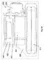
図2〜図6に示されるとおり、本発明に係る手術用アクセス装置200は、例えば可撓性開創器310(図3)などの、任意の所望のチューブ状手術用アクセス装置と共に使用するように適合及び構成され得る。例示的な開創器が、米国特許第5,524,644号明細書、米国特許第3,347,226号明細書、米国特許第3,347,227号明細書、米国特許第5,159,921号明細書、米国特許第5,524,644号明細書、米国特許第6,450,983号明細書、米国特許第6,254,534号明細書、米国特許第6,846,287号明細書、米国特許第5,672,168号明細書、米国特許第5,906,577号明細書、米国特許第6,142,936号明細書、米国特許第5,514,133号明細書、米国特許第7,238,154号明細書、米国特許第6,945,932号明細書、米国特許第6,908,430号明細書、米国特許第6,972,026号明細書、米国特許第5,741,298号明細書、又は米国特許第6,945,932号明細書(これらの開示は全体として参照により本明細書に援用される)に記載されている。 As shown in FIGS. 2-6, the
かかる実施形態において、開創器は、患者に形成された切開を通じて挿入され、任意の好適な手段によって固定されてもよい。次に本体120が、機械式シールを導入することなく、吹送、再循環及び/又はフィルタリング及び/又は流体封止機能を提供して吹送時の腹圧の損失を防ぐことを目的として、締まり嵌め、摩擦嵌め、クランプ、ストラップ又は開創器の近位端に固定される他の方法によるなどして固定されてもよい。 In such embodiments, the retractor may be inserted through an incision made in the patient and secured by any suitable means. The
示されるとおり、及び図4〜図6の断面図で最も良く分かるとおり、シース本体312と遠位リング313及び近位リング311とを含む可撓性開創器300は、手術用アクセス装置200のハウジング220の拡大した直径部分にある遠位に位置決めされた溝429に着座する。遠位リング311及び近位リング313は、典型的には、ゴム、気泡ゴムなどの柔軟材料で作製され、従って固有の形状及びサイズを有する。切開を通じて開創器300が挿入され、患者に固定されるとき、丸めるか、又は他の技術によるなどして、ハウジング200がそこに適用されてもよく、最初に挿入中に近位リング311が圧縮され、次に拡張して溝429内に嵌入する。内部フープ応力によってリング311、従って開創器300が溝429内に維持され、そこからの意図しない脱落が抑制される。 As shown and best seen in the cross-sectional views of FIGS. 4-6, the flexible retractor 300 including the
限定はされないが、例えば、クランプ装置などを使用して、ハウジングが開創器のルーメン内に少なくとも部分的に着座することを含め、開創器310とハウジング200との間の代替的な接続が考えられる。 Alternative connections between the
図1の手術用アクセス装置100と同様に、図2〜図6の手術用アクセス装置200はハウジング220を含み、そこからコネクタ225が延在する。以下で図4〜図6に関連してさらに詳細に説明するその内部構成要素は、リテーナによってハウジング内に保持され、リテーナはスナップ・リング又は「サークリップ」260として具体化され、これを使用すると比較的ロー・プロファイルが維持されるが、他の構成も可能である。 Similar to the
図4〜図6の断面図で最も良く分かるとおり、手術用アクセス装置200は比較的ロー・プロファイルで提供され、図1のアクセス装置100と同様に、より一般的な手術用アクセス装置と比べて、そこを通じて挿入される手術器具の動作上の制限を小さくすることができる。アクセス装置200は、ハウジング220の遠位端から遠位に延在する可撓性開創器310に適合可能なハウジング220を含む。 As best seen in the cross-sectional views of FIGS. 4-6, the
本発明に従えば、アクセス装置200は吹送機能を含んでもよく、そこを通じて挿入される器具の周りに流体シール又は気圧バリアを形成するように適合及び構成されてもよく、及び/又は吹送ガスの再循環を促進するように適合されてもよい。 In accordance with the present invention, the
示されるとおり、手術用アクセス装置200は、ハウジング220内に画定される加圧流体プレナム423を含む。示される実施形態において、プレナム423は、ハウジング220と下側インサート430と上側インサート440との間に画定される。プレナム423は、少なくとも1つのノズル428と流体連通し、加圧流体をプレナム423から開創器の中心ルーメン418へと実質的に軸方向に誘導することにより、そこを通じて挿入された手術器具の周りに、及び/又は器具がそこを通じて挿入されていないときには、例えばルーメン418にわたって、一定のガス・シールを設けるように構成される。 As shown,
同様に、示されるとおり、アクセス装置200には、ハウジング220と下側インサート430との間に再循環チャンバ421が画定されてもよい。弾性Oリングなどの1つ又は複数の封止要素が、第1のインサート430及び第2のインサート440の各々にそれぞれ形成される環状の座部に提供されてもよい。ハウジング220には、ルーメン118とコネクタ225との間に、接続されたシステムの再循環部分にガスが入ることを可能にする穴422が提供される。 Similarly, as shown, the
1つ又は複数の追加のチャンバ又は他の流体通路若しくは導管424がさらに提供されてもよく、それにより圧力検知装置及び/又は手術用インサフレーターと作業部位との間の流体連通が促進される。流体導管が、そこに接続された開創器の内側又は外側の表面の壁内に、又は表面上に形成されてもよい。或いは、それが所望であれば、かかる目的で別個のチューブがルーメン418に挿通されてもよい。さらなる代替的実施形態において、及び例えば図2〜図6の実施形態に示されるとおり、圧力検知及び/又は吹送穴424が、単純にルーメン418の上側部分と流体連通していてもよい。 One or more additional chambers or other fluid passages or
示されるとおり、接続部225がハウジング220に提供され、これは、そこに形成された、前述のチャンバ及び/又は導管の1つと流体連通する少なくとも1つのチャネルを有する。接続部225は、そこに、及びハウジング220に形成された通路によってかかるチャンバ及び/又は導管と流体連通している。接続部225は、単一のセットとして具体化されてもよい複数の導管の、アクセス装置200との接続を促進する。次に導管が、吹送装置、再循環装置などを含む適当な機器と接続される。 As shown, a
例えば、ルーメン418の中心軸と垂直な平面の断面では、ハウジング220のルーメン部分の断面形状は、円形、卵形、楕円形又はその他の長円形の形状であってもよい。 For example, in a cross-section in a plane perpendicular to the central axis of the
図6の断面図に示されるとおり、近位キャップ650がハウジング220に適用されてもよく、これは、吸音材料又は音響減衰面機構などの、アクセス装置のルーメン418を通じて流れる流体によって生じる音を吸収、消去又は低減する音響減衰機構を組み込むことができる。場合により内部スカート660が提供され、ハウジング220及びルーメン418内に着座する。スカート660のハウジング部分に、流体が再循環プレナム421に入ることを可能にする穴が形成されてもよい。さらに、チューブ又は他の通路がスカート660に一体化されてもよく、コネクタ425のそれぞれの通路を通じて接続されて、取り付けられたシステムの圧力検知及び/又は吹送構成要素と流体連通する。 As shown in the cross-sectional view of FIG. 6, a
図7〜図11は、本発明に係るさらなる手術用アクセス装置700を示し、これは、前述の実施形態のものと実質的に同様の、及び同じ任意の機構を含み得る内部構成要素を備えた、コネクタ725を備えるハウジング720を含み、これらについては、簡単にするため、この実施形態に関連しては詳細に考察しない。しかしながら、手術用アクセス装置700は、前述の実施形態のものとは異なるアンカー機構を含む。手術用アクセス装置700はスプリング・アンカー715を含み、これらは、ハウジング720に、又はそれに代えてハウジング720の表面上に形成されたトラックに提供され、ストッパ716で終端となる。スプリング・アンカーは、アクセス装置700を患者の腹壁に固定する一方、腹壁への外傷を防止するにように形成され、従って、その遠位端に返し屈曲部を含む。スプリング・アンカーはハウジング720内に維持され、展開されないものであってもよく、又はアクセス装置700が挿入されると格納位置から展開されてもよい。スプリング・アンカー715は、限定はされないが、ステンレス鋼又は形状記憶合金を含めた、任意の好適な材料で形成されてよい。 FIGS. 7-11 illustrate a further
好ましい態様に従えば、アクセス装置700には、適合性を有するオブチュレータ790が提供され、これは対向する平面状のスロット795を有し、スロット内に、スロット795の底表面からオフセットしてスタブ792が延在する。図11の分解部分図で最も良く分かるとおり、スプリング・アンカー715にはノッチ1116が画定される。オブチュレータ790が長手方向に前進すると、スタブ792がノッチ1116を通過し、スロット795と組み合わさってスプリング・アンカー715を係合し、それらを、その本質的に湾曲した構成から直線状に延ばす。オブチュレータ790を使用して、アクセス装置700を挿入する間、並びに患者からそれを取り出す間、スプリング・アンカー715を直線状に延ばされた構成に保持することができる。 In accordance with a preferred embodiment, the
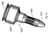
図12〜図13は、本発明に係るさらなる手術用アクセス装置1200を示し、これは、前述の実施形態のものと実質的に同様の、及び同じ任意の機構を含み得る内部構成要素を備えた、コネクタ1225を備えるハウジング1220を含み、これらについては、簡単にするため、この実施形態に関連しては詳細に考察しない。 FIGS. 12-13 illustrate a further
手術用アクセス装置1200は、前述の実施形態のものとさらに異なるアンカー機構を含む。手術用アクセス装置1200はスプリング・アンカー1215を含み、これらは、アクセス装置1200を挿入する間、手術用オブチュレータ1290として、又はそれと一体化して機能し得る遠位端キャップ1210により維持される。アクセス装置1200が患者の腹壁に形成された切開に完全に挿入されると、キャップ1210が、キャップを遠位に押し退けることによって取り外される。キャップ1210を再度アクセス装置1200に嵌めると、アクセス装置1200を取り出すことが可能となる。
スプリング・アンカー1215は、形状記憶合金を含む任意の好適な材料で形成することができる。 The
示されるとおり、アクセス装置の本体は、腹壁へのアクセス装置1200の固定を補助する調整可能なベロー部分1230を含む。アクセス装置1200を最初に挿入した後、本体の遠位端部分1229を近位に引き込んでもよく、それにより腹壁が事実上挟まれ、そこにアクセス装置1200が固定される。かかる接続は、オブチュレータ1290を挿入する間、伸展した構成に維持されるばね荷重式の構成要素か、又はそれに代えて、遠位端部分1229に取り付けられて近位に引っ張られるケーブル装置によって達成することができる。 As shown, the body of the access device includes an
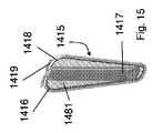
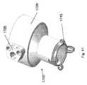
図14〜図16は、本発明に係るさらなる手術用アクセス装置1400を示し、これは、前述の実施形態のものと実質的に同様の、及び同じ任意の機構を含み得る内部構成要素を備えた、コネクタ1425を備えるハウジング1420を含み、これらについては、簡単にするため、この実施形態に関連しては詳細に考察しない。 14-16 illustrate a further
手術用アクセス装置1400は遠位アンカー要素1415を含み、これらは、限定はされないが、例えばステンレス鋼又は形状記憶合金を含めた、任意の好適な材料で形成することができる。アンカー要素1415は、手術用オブチュレータ1490の遠位端部分1410と係合すると、直線状の配置に維持される(図14)。図15で最も良く分かるとおり、トラック1417がアンカー要素1415と一体化され、オブチュレータ1490上の1つ又は複数の突起を係合してアンカー要素1415を所望の位置に維持するように構成される。アンカー要素1415のフレーム1416が全体の形状を画定し、これは旋回軸1419で終端となる。フレーム1416にはコーティング1418が施され、これは緩衝材料で作製されてもよく、それにより患者に対する外傷が最小限に抑えられ、及び/又はアクセス装置1400の留置が促進される。緩衝材料は、例えばシリコーン・ゴムであってもよいが、別の好適な材料であってもよく、フレーム1416内に画定されるウェブ1481内まで延在して、アンカー要素1415の表面積を事実上増加させてもよい。
図16は、そこからオブチュレータ1490が取り外されたアクセス装置1400を示す。 FIG. 16 shows the
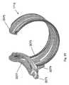
図17〜図26は、本発明に係る手術用アクセス装置1700のさらなる実施形態、及びそのアンカー要素1715の詳細図を示す。手術用アクセス装置は図14〜図16の実施形態と同様であり、上記に記載されるとおりの内部構成要素を備えるハウジング1720、接続要素1725及びアンカー要素1715を含む。 FIGS. 17-26 show a further embodiment of a
図18及び図19に示されるとおり、アクセス装置1700と共に使用されるオブチュレータは、関節式フック1811によってアンカー要素1715を係合する遠位端部分1810を含む。関節式フック1811を挿入すると、アンカー要素1715は、挿入する間は直線状の位置に維持され、アクセス装置1700が患者の腹壁に完全に挿入されると解除される。 As shown in FIGS. 18 and 19, the obturator used with the
図14〜図16のアクセス装置1400と同様に、アクセス装置1700は複数の円周方向に配設されたアンカー1715を含み、これらは、限定はされないが、ステンレス鋼又は形状記憶合金といった材料で形成される。或いは、この実施形態又は本明細書に記載される他の実施形態では、弾性ポリマー材料が使用されてもよい。被覆材、ウェブ要素などを含む任意の機構が、有利な効果に加えられてもよい。 Similar to the
図21は、手術用アクセス装置1700の上面図であり、全体的な断面形状及び実質的に楕円形の形状を有するルーメンを示す。上記に記載されるとおり、限定はされないが、円形、ネコの目形状又は別の構成の長円形を含む代替的な形状が可能である。 FIG. 21 is a top view of a
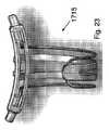
図22〜図26で最も良く分かるとおり、アンカー1715は、主本体2275、スプリング要素2273、本体2275から延在するピン2271、1つ又は複数のストラット2277を含む。本体2275は、限定はされないが、ポリマー材料を含む任意の好適な材料で形成することができる。アンカー1715の湾曲しようとする傾向は、示される実施形態ではスプリング要素2273によって付与され、スプリング要素2273は、前述の実施形態と同様に、限定はされないが、ポリマー材料及び形状記憶合金を含む金属を含めた、任意の好適な材料で形成することができる。 As best seen in FIGS. 22-26,
ピン2272は、アンカー1715を手術用アクセス装置1700の本体1720に固定するために提供される。アンカー1715には、アンカー1715を本体1720にさらに固定する突起2279がさらに提供されてもよい。 Pin 2272 is provided to secure
図27〜図29はアクセス装置2700を示し、これは、その本体2720の遠位端部分2710に形成されたスロット2712を含む。この機構は、細長本体を含む、本明細書に記載される任意の他の実施形態に適用することができる。スロットにより、アクセス装置2700を通じて挿入された手術器具2799の可動域を拡げることが可能となる。上述の実施形態と同様に、ハウジング2720は接続部2725を含む。図28〜図29で最も良く分かるとおり、断面形状は実質的に楕円形であるが、上述されるとおり、或いは別の形状を有してもよい。 FIGS. 27-29 show an
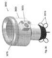
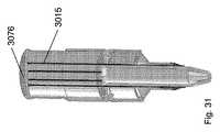
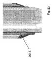
図30〜図33は、接続部3025を備えたハウジング3020を有する、本発明に係る手術用アクセス装置3000のさらなる実施形態を示す。手術用アクセス装置3000は、その遠位端部分に円周方向に配設された環状にコイル状にされたアンカー要素3015を含む。軸方向に移動可能なアクチュエータ3076がアンカー要素3015に関連して提供され、アンカー要素3015は、収縮時、アクセス装置3000の本体3020内に収まる。アクチュエータ3076が遠位に押されると、アンカー要素3015がハウジング3020の遠位端から伸展し、アクセス装置3000の長手方向軸と垂直な半径方向の平面でコイル状になる。展開されると、アンカー要素3015は腹壁に当接し、従ってアクセス装置3000の留置に役立つ。前述の実施形態と同様に、アンカー要素3015はスプリング材料で形成されてもよく、スプリング材料は、例えば、弾性ポリマー材料であっても、又はステンレス鋼若しくは形状記憶合金などの金属であってもよい。 30-33 show a further embodiment of a
図34及び図35は、さらに別の代替的なアンカー機構を有する手術用アクセス装置3400を示し、そのハウジング3420に提供された1つ又は複数のシャフト3417によって作動する半径方向に展開可能なアンカー要素3415を備える。切開を通じてアクセス装置が挿入されると、アンカー要素3415が展開され、アクセス装置3400が患者の腹壁に留置される。 FIGS. 34 and 35 illustrate a
上述されるとおり、本発明の一実施形態に関連して記載される適合性を有する特徴が、有利には、本発明の他の実施形態に組み込まれ得る。上記に記載され、図面に示されるとおりの本発明の装置及び関連する方法は、患者に対して過剰な外傷を引き起こすことのないアンカー機能を含む有利な特性を備える手術用アクセス装置を提供する。当業者には、本発明の趣旨及び範囲から逸脱することなく、本発明の装置、システム及び関連する方法に様々な修正及び変更が加えられ得ることは明らかであろう。 As described above, the compatible features described in connection with one embodiment of the present invention may be advantageously incorporated into other embodiments of the present invention. The apparatus of the present invention and related methods as described above and shown in the drawings provide a surgical access device with advantageous properties including an anchoring feature that does not cause excessive trauma to the patient. It will be apparent to those skilled in the art that various modifications and variations can be made to the apparatus, system and related methods of the present invention without departing from the spirit and scope of the invention.
Claims (8)
Translated fromJapanese患者の腹壁に形成された切開を通じて少なくとも部分的に延在するように適合及び構成された、前記ハウジングの前記遠位端から遠位に延在するアクセス・チューブであって、切開からの脱落を抑制する直径が拡大した遠位部分を備える双曲線形の断面形状を有するアクセス・チューブと、
を含む、手術用アクセス装置。A housing having a proximal end portion and a distal end portion;
An access tube extending distally from the distal end of the housing and adapted and configured to extend at least partially through an incision formed in a patient's abdominal wall, wherein An access tube having a hyperbolic cross-sectional shape with a distal portion having an enlarged constraining diameter;
Surgical access device comprising:
前記近位ハウジングが、前記近位ハウジングに画定されたプレナム・チャンバを有し、前記プレナム・チャンバが、少なくとも1つのノズルと流体連通し、加圧流体を前記プレナム・チャンバから前記手術用アクセス装置の中心穴へと軸方向に誘導することにより、そこを通じて挿入された手術器具の周りに一定のガス・シールを設け、同時にそこを通じた体腔からの加圧流体の損失を抑制するように構成され、及び前記プレナム・チャンバが、加圧流体を受け取り、前記加圧流体を前記少なくとも1つのノズルに導くように適合及び構成される、手術用アクセス装置。A proximal housing having a proximal end portion and a distal end portion, wherein the distal end portion of the housing is configured and adapted to engage a proximal portion of a flexible retractor; A surgical access device including a proximal housing comprising:
The proximal housing has a plenum chamber defined in the proximal housing, the plenum chamber in fluid communication with at least one nozzle, and pressurized fluid from the plenum chamber to the surgical access device It is configured to provide a constant gas seal around the surgical instrument inserted therethrough, while at the same time suppressing the loss of pressurized fluid from the body cavity therethrough by guiding axially into the central hole of the And the plenum chamber is adapted and configured to receive pressurized fluid and direct the pressurized fluid to the at least one nozzle.
Applications Claiming Priority (3)
| Application Number | Priority Date | Filing Date | Title |
|---|---|---|---|
| US10447508P | 2008-10-10 | 2008-10-10 | |
| US61/104,475 | 2008-10-10 | ||
| PCT/US2009/060299WO2010042915A2 (en) | 2008-10-10 | 2009-10-10 | Low-profile surgical access devices with anchoring |
Publications (3)
| Publication Number | Publication Date |
|---|---|
| JP2012505057Atrue JP2012505057A (en) | 2012-03-01 |
| JP2012505057A5 JP2012505057A5 (en) | 2012-07-19 |
| JP5745413B2 JP5745413B2 (en) | 2015-07-08 |
Family
ID=42101253
Family Applications (1)
| Application Number | Title | Priority Date | Filing Date |
|---|---|---|---|
| JP2011531240AActiveJP5745413B2 (en) | 2008-10-10 | 2009-10-10 | Low profile surgical access device with anchor mechanism |
Country Status (7)
| Country | Link |
|---|---|
| US (2) | US9289233B2 (en) |
| EP (1) | EP2349033B1 (en) |
| JP (1) | JP5745413B2 (en) |
| KR (3) | KR101829726B1 (en) |
| CN (1) | CN102264309B (en) |
| ES (1) | ES2817573T3 (en) |
| WO (1) | WO2010042915A2 (en) |
Cited By (2)
| Publication number | Priority date | Publication date | Assignee | Title |
|---|---|---|---|---|
| JP2013085933A (en)* | 2011-10-17 | 2013-05-13 | Takeshi Ohira | Solitary foramen endoscopic surgical port |
| JP2018526112A (en)* | 2015-09-01 | 2018-09-13 | サージクエスト, インク.Surgiquest, Inc. | Multi-port access device for minimally invasive surgical procedures |
Families Citing this family (38)
| Publication number | Priority date | Publication date | Assignee | Title |
|---|---|---|---|---|
| KR101829726B1 (en) | 2008-10-10 | 2018-02-19 | 서지퀘스트, 인코포레이티드 | Low-profile surgical access devices with anchoring |
| US20190167302A9 (en)* | 2008-10-10 | 2019-06-06 | Surgiquest, Inc. | Low-profile surgical access devices with anchoring |
| WO2010068265A1 (en) | 2008-12-10 | 2010-06-17 | Minimally Invasive Devices, Llc | Systems and methods for optimizing and maintaining visualization of a surgical field during the use of surgical scopes |
| JP5415925B2 (en)* | 2009-03-02 | 2014-02-12 | オリンパス株式会社 | Endoscope |
| US8747297B2 (en)* | 2009-03-02 | 2014-06-10 | Olympus Corporation | Endoscopic heart surgery method |
| US8206291B2 (en)* | 2009-03-27 | 2012-06-26 | Tyco Healthcare Group Lp | Portal device |
| EP2481377A4 (en)* | 2009-09-22 | 2017-12-20 | Olympus Corporation | Space-securing device |
| US8932212B2 (en) | 2009-10-01 | 2015-01-13 | Covidien Lp | Seal anchor with non-parallel lumens |
| EP2485664B1 (en)* | 2009-10-10 | 2019-02-27 | SurgiQuest, Incorporated | Low-profile surgical access devices |
| US20110112373A1 (en)* | 2009-11-10 | 2011-05-12 | Trans1 Inc. | Soft tissue access apparatus and methods for spinal surgery |
| US9078562B2 (en) | 2010-01-11 | 2015-07-14 | Minimally Invasive Devices, Inc. | Systems and methods for optimizing and maintaining visualization of a surgical field during the use of surgical scopes |
| JP5914466B2 (en)* | 2010-05-24 | 2016-05-11 | サージクェスト,インコーポレーテッド | Automatic surgical device |
| US20110301419A1 (en)* | 2010-06-07 | 2011-12-08 | Brandon Wesley Craft | Pressure feedback access ports for minimally invasive surgery |
| JP5968886B2 (en) | 2010-08-04 | 2016-08-10 | ミニマリー インべーシブ デバイシーズ, インコーポレイテッド | System and method for optimizing and maintaining operative field visualization while using a surgical microscope |
| JP6396657B2 (en)* | 2010-10-01 | 2018-09-26 | アプライド メディカル リソーシーズ コーポレイション | Natural orifice surgery system |
| US9522017B2 (en) | 2010-12-03 | 2016-12-20 | Minimally Invasive Devices, Inc. | Devices, systems, and methods for performing endoscopic surgical procedures |
| US9149265B2 (en) | 2011-02-26 | 2015-10-06 | Abbott Cardiovascular Systems, Inc. | Hinged tissue support device |
| WO2012122263A2 (en) | 2011-03-08 | 2012-09-13 | Surgiquest, Inc. | Trocar assembly with pneumatic sealing |
| WO2014100210A1 (en) | 2012-12-19 | 2014-06-26 | Surgiquest, Inc. | Coupling for connecting a tube set to a trocar |
| US9486132B2 (en)* | 2013-01-17 | 2016-11-08 | Abbott Cardiovascular Systems, Inc. | Access device for accessing tissue |
| WO2014151824A1 (en) | 2013-03-14 | 2014-09-25 | Minimally Invasive Devices, Inc. | Fluid dispensing control systems and methods |
| ES2806266T3 (en) | 2013-03-15 | 2021-02-17 | Applied Med Resources | Trocar Surgical Seal Gasket |
| WO2015084157A1 (en)* | 2013-12-04 | 2015-06-11 | Fortimedix Surgical B.V. | Access device and assembly comprising such device |
| USD753303S1 (en) | 2014-07-29 | 2016-04-05 | Ethicon Endo-Surgery, Llc | Trocar |
| JP7080642B2 (en)* | 2015-04-23 | 2022-06-06 | アプライド メディカル リソーシーズ コーポレイション | Tissue retrieval system and method |
| US10213194B2 (en) | 2016-09-27 | 2019-02-26 | Ethicon, Inc. | Surgical retraction systems including sternal retractors and hemostatic inserts |
| US10806490B2 (en) | 2017-03-08 | 2020-10-20 | Conmed Corporation | Single lumen gas sealed access port for use during endoscopic surgical procedures |
| CN106963379B (en)* | 2017-03-17 | 2020-08-21 | 中国人民解放军第三军医大学第一附属医院 | Terahertz imaging system |
| US10413324B2 (en) | 2017-10-23 | 2019-09-17 | Conmed Corporation | Devices for performing minimally invasive surgery having foam support housing |
| US10463396B2 (en) | 2017-10-23 | 2019-11-05 | Conmed Corporation | Devices for performing minimally invasive surgery having bellows support housing |
| US10405884B2 (en) | 2017-10-23 | 2019-09-10 | Conmed Corporation | Devices for performing minimally invasive surgery having rotating multiport access |
| JP2021164491A (en)* | 2018-04-11 | 2021-10-14 | オリンパス株式会社 | Endoscope fluid controller |
| TWI865458B (en)* | 2018-08-17 | 2024-12-11 | 紐西蘭商費雪派克保健有限公司 | Venting surgical cannula and system for providing gases to a patient |
| WO2020036498A1 (en)* | 2018-08-17 | 2020-02-20 | Fisher & Paykel Healthcare Limited | Directed gas flow surgical cannula for providing gases to a patient |
| CN109124738B (en)* | 2018-08-28 | 2021-02-09 | 浙江天松医疗器械股份有限公司 | Puncture outfit casing pipe and use method of inner pipe and outer pipe thereof |
| US11013530B2 (en) | 2019-03-08 | 2021-05-25 | Medos International Sarl | Surface features for device retention |
| US10932818B2 (en) | 2019-05-07 | 2021-03-02 | Covidien Lp | Removable seal assembly and access system including the same |
| US20220211263A1 (en)* | 2021-03-23 | 2022-07-07 | Axcess Instruments Inc. | Multi-piece access port imaging systems |
Citations (3)
| Publication number | Priority date | Publication date | Assignee | Title |
|---|---|---|---|---|
| JP2002508195A (en)* | 1997-12-11 | 2002-03-19 | スミス アンド ネフュー インコーポレーテッド | Laparoscopic surgical access port with controlled sealing valve |
| JP2007044395A (en)* | 2005-08-12 | 2007-02-22 | Hakko Co Ltd | Wound retractor |
| JP2008515523A (en)* | 2004-10-11 | 2008-05-15 | アトロポス・リミテッド | Instrument access device |
Family Cites Families (76)
| Publication number | Priority date | Publication date | Assignee | Title |
|---|---|---|---|---|
| US4184510A (en) | 1977-03-15 | 1980-01-22 | Fibra-Sonics, Inc. | Valued device for controlling vacuum in surgery |
| US4535773A (en) | 1982-03-26 | 1985-08-20 | Inbae Yoon | Safety puncturing instrument and method |
| US4735603A (en) | 1986-09-10 | 1988-04-05 | James H. Goodson | Laser smoke evacuation system and method |
| US4792335A (en) | 1987-02-11 | 1988-12-20 | Goosen Carl C | Pressure controlled valve apparatus |
| DE3739003A1 (en) | 1987-11-17 | 1989-05-24 | Wolf Gmbh Richard | INSUFFLATION DEVICE FOR ENDOSCOPIC INTERVENTIONS |
| US4943280A (en) | 1987-12-31 | 1990-07-24 | United States Surgical Corporaiton | Self-seating flapper valve for an insufflation cannula assembly |
| US4869717A (en) | 1988-04-25 | 1989-09-26 | Adair Edwin Lloyd | Gas insufflation needle with instrument port |
| US5002557A (en)* | 1989-04-06 | 1991-03-26 | Hasson Harrith M | Laparoscopic cannula |
| US5429483A (en) | 1989-09-22 | 1995-07-04 | Tamari; Yehuda | Pressure sensitive valves for extracorporeal pumping |
| US5199944A (en) | 1990-05-23 | 1993-04-06 | Ioan Cosmescu | Automatic smoke evacuator system for a surgical laser apparatus and method therefor |
| CA2052310A1 (en)* | 1990-10-09 | 1992-04-10 | Thomas L. Foster | Surgical access sheath |
| US5203767A (en) | 1991-01-08 | 1993-04-20 | Cloyd David W | Laparoscopic surgical gauze and the like |
| US5284473A (en) | 1991-07-16 | 1994-02-08 | C. R. Bard, Inc. | Perfusion catheter with flow amplifier |
| US5328458A (en) | 1991-12-03 | 1994-07-12 | Olympus Optical Co., Ltd. | Insufflation apparatus |
| US5190068A (en) | 1992-07-02 | 1993-03-02 | Brian Philbin | Control apparatus and method for controlling fluid flows and pressures |
| US5300047A (en) | 1992-09-29 | 1994-04-05 | Beurrier Henry R | Trocar cannula and catheter |
| US5312351A (en) | 1993-01-29 | 1994-05-17 | Gerrone Carmen J | Combined pneumo-needle and trocar apparatus |
| CA2126150C (en)* | 1993-07-14 | 2005-02-22 | David T. Green | Seal assembly for accommodating introduction of surgical instruments |
| US5366446A (en)* | 1993-11-17 | 1994-11-22 | Unisurge, Inc. | Introducer assembly |
| US5800381A (en) | 1994-02-25 | 1998-09-01 | Ognier; Jean-François | Medical gas insufflator with automatic gas flow control |
| US5545150A (en) | 1994-05-06 | 1996-08-13 | Endoscopic Concepts, Inc. | Trocar |
| WO1996001132A1 (en) | 1994-07-01 | 1996-01-18 | Northgate Technologies Incorporated | High flow insufflation instrument for laparoscopic surgery |
| US6162196A (en)* | 1994-07-14 | 2000-12-19 | Applied Medical Resources Corporation | Multiport access device |
| US5569205A (en) | 1994-07-14 | 1996-10-29 | Hart; Charles C. | Multiport trocar |
| US5849005A (en) | 1995-06-07 | 1998-12-15 | Heartport, Inc. | Method and apparatus for minimizing the risk of air embolism when performing a procedure in a patient's thoracic cavity |
| US5556386A (en) | 1995-04-03 | 1996-09-17 | Research Medical, Inc. | Medical pressure relief valve |
| US5634937A (en)* | 1995-05-19 | 1997-06-03 | General Surgical Innovations, Inc. | Skin seal with inflatable membrane |
| DE19523685A1 (en) | 1995-07-04 | 1997-01-09 | Guenter Schaller | Means of assistance for use with a trocar - has hollow body formed by two elastomers with suction source connected to it and gas supply from insufflator connected to other side of valve to chamber. |
| US5545179A (en)* | 1995-07-21 | 1996-08-13 | Ethicon Endo-Surgery, Inc. | Endoscopic access assembly |
| CA2270206C (en) | 1996-11-04 | 2008-01-08 | Frederick Paget Milsom | Cardiac recovery |
| US6228058B1 (en) | 1997-04-03 | 2001-05-08 | Core Dynamics, Inc. | Sleeve trocar with penetration indicator |
| US5906577A (en)* | 1997-04-30 | 1999-05-25 | University Of Massachusetts | Device, surgical access port, and method of retracting an incision into an opening and providing a channel through the incision |
| EP2111884A1 (en) | 1997-05-28 | 2009-10-28 | United States Surgical Corporation | Trocar seal system |
| US5916198A (en) | 1997-08-05 | 1999-06-29 | Femrx, Inc. | Non-binding surgical valve |
| US6299592B1 (en) | 1998-03-31 | 2001-10-09 | Northgate Technologies Inc. | Laparoscopic insufflator |
| US6544210B1 (en) | 1998-10-22 | 2003-04-08 | Gregory J. Trudel | Disposable laparoscopic smoke evacuation system |
| US6102042A (en) | 1998-12-22 | 2000-08-15 | Respironics, Inc. | Insufflation system, attachment and method |
| MXPA01013402A (en) | 1999-06-22 | 2004-03-10 | E Blanco Ernesto | Safety trocar with progressive cutting tip guards and gas jet tissue deflector. |
| US6253766B1 (en) | 1999-08-24 | 2001-07-03 | Dhd Healthcare Corporation | Continuous positive airway pressure therapy device |
| US7494485B2 (en) | 1999-12-10 | 2009-02-24 | Sprite Solutions | Fluidic interventional device and method of distal protection |
| US6302873B1 (en) | 2000-02-23 | 2001-10-16 | Stephen P. Moenning | Minimally invasive medical apparatus for dispensing a biologically active compound and an associated medical procedure for dispensing a biologically active compound |
| JP2004509659A (en) | 2000-05-30 | 2004-04-02 | ジェニコン エルシー | Trocar system incorporating shielded trocar, knobbed cannula, removable end housing, and flexible valve system and methods of use thereof |
| US20020161387A1 (en) | 2000-06-22 | 2002-10-31 | Blanco Ernesto E. | Safety trocar with progressive cutting tip guards and gas jet tissue deflector |
| US6811546B1 (en)* | 2000-08-25 | 2004-11-02 | Origin Medsystems, Inc. | Endoscopic surgical access port and method |
| US6551270B1 (en)* | 2000-08-30 | 2003-04-22 | Snowden Pencer, Inc. | Dual lumen access port |
| JP2002204829A (en) | 2000-09-08 | 2002-07-23 | Pall Corp | Cannula assembly |
| GB0025710D0 (en) | 2000-10-20 | 2000-12-06 | Medical Res Council | Biolistic device |
| US6942671B1 (en) | 2000-11-06 | 2005-09-13 | Tyco Healthcare Group Lp | Surgical sealing apparatus |
| US6508859B1 (en) | 2000-11-13 | 2003-01-21 | Porous Media Corporation | Method and apparatus for removing air or gas from fluid |
| US6905489B2 (en) | 2001-04-24 | 2005-06-14 | Northgate Technologies, Inc. | Laparoscopic insertion device |
| EP1418850B1 (en) | 2001-08-01 | 2010-10-06 | Tyco Healthcare Group LP | Apparatus for providing percutaneous access and medicament to a target surgical site |
| US6989003B2 (en) | 2001-08-31 | 2006-01-24 | Conmed Corporation | Obturator and cannula for a trocar adapted for ease of insertion and removal |
| EP1441636B1 (en) | 2001-10-20 | 2012-01-11 | Applied Medical Resources Corporation | Sealed surgical access device |
| EP2343032B1 (en)* | 2002-06-05 | 2012-05-09 | Applied Medical Resources Corporation | Wound retractor |
| US20040034339A1 (en) | 2002-08-16 | 2004-02-19 | The Regents Of The University Of California | Device for improved visualization of operative sites during surgery |
| US7056329B2 (en) | 2002-10-23 | 2006-06-06 | Intellimed Surgical Solutions, Llc | Laparoscopic direct vision dissecting port |
| DE60325879D1 (en) | 2002-11-08 | 2009-03-05 | Tyco Healthcare | SELF-CLOSING CANNULA |
| US7182752B2 (en) | 2003-04-08 | 2007-02-27 | Surgiquest, Incorporated | Continuous gas flow trocar assembly |
| US7338473B2 (en) | 2003-04-08 | 2008-03-04 | Surgiquest, Incorporated | Pneumoseal trocar arrangement |
| US7285112B2 (en) | 2003-04-08 | 2007-10-23 | Surgiquest, Incorporated | Gas flow trocar arrangement |
| US7854724B2 (en)* | 2003-04-08 | 2010-12-21 | Surgiquest, Inc. | Trocar assembly with pneumatic sealing |
| US7163510B2 (en)* | 2003-09-17 | 2007-01-16 | Applied Medical Resources Corporation | Surgical instrument access device |
| JP2005110978A (en) | 2003-10-08 | 2005-04-28 | Olympus Corp | Gas feeding device |
| US7297141B2 (en) | 2004-01-20 | 2007-11-20 | Ethicon Endo-Surgery, Inc. | Method for accessing an operative space |
| US20060217665A1 (en)* | 2004-11-18 | 2006-09-28 | Laparoscopic Partners Llc | Surgical instrument seal assembly and triple lead thread |
| US7628590B2 (en) | 2005-02-16 | 2009-12-08 | Sterling Investments Lc | Method and apparatus for reducing free flow risk |
| US20060247678A1 (en)* | 2005-04-08 | 2006-11-02 | Weisenburgh William B Ii | Surgical instrument system |
| WO2008030256A1 (en)* | 2006-09-08 | 2008-03-13 | Surgiquest, Incorporated | Trocar assembly with pneumatic sealing |
| EP2101662B1 (en)* | 2006-12-18 | 2018-07-11 | SurgiQuest, Incorporated | System for surgical insufflation and gas recirculation |
| WO2008093313A1 (en) | 2007-02-01 | 2008-08-07 | Atropos Limited | An instrument insertion device |
| WO2008141291A1 (en)* | 2007-05-11 | 2008-11-20 | Applied Medical Resources Corporation | Surgical retractor with gel pad |
| KR101829726B1 (en) | 2008-10-10 | 2018-02-19 | 서지퀘스트, 인코포레이티드 | Low-profile surgical access devices with anchoring |
| DE102008056005B3 (en) | 2008-11-05 | 2010-04-22 | Carsten Michalski | Electro-optical measuring system |
| EP2485664B1 (en) | 2009-10-10 | 2019-02-27 | SurgiQuest, Incorporated | Low-profile surgical access devices |
| US9662002B2 (en) | 2014-07-10 | 2017-05-30 | Amendia, Inc. | Endoscopic portal protective shield assembly |
| US10524831B2 (en) | 2015-03-20 | 2020-01-07 | Spinecraft, LLC | MIS access port and methods of using |
- 2009
- 2009-10-10KRKR1020177014703Apatent/KR101829726B1/enactiveActive
- 2009-10-10EPEP09820023.1Apatent/EP2349033B1/enactiveActive
- 2009-10-10WOPCT/US2009/060299patent/WO2010042915A2/enactiveApplication Filing
- 2009-10-10KRKR1020167021622Apatent/KR20160099114A/ennot_activeCeased
- 2009-10-10KRKR1020117009618Apatent/KR20110079885A/ennot_activeCeased
- 2009-10-10JPJP2011531240Apatent/JP5745413B2/enactiveActive
- 2009-10-10CNCN200980149241.XApatent/CN102264309B/enactiveActive
- 2009-10-10ESES09820023Tpatent/ES2817573T3/enactiveActive
- 2009-10-11USUS12/577,189patent/US9289233B2/enactiveActive
- 2010
- 2010-10-08USUS13/388,644patent/US9597112B2/enactiveActive
Patent Citations (3)
| Publication number | Priority date | Publication date | Assignee | Title |
|---|---|---|---|---|
| JP2002508195A (en)* | 1997-12-11 | 2002-03-19 | スミス アンド ネフュー インコーポレーテッド | Laparoscopic surgical access port with controlled sealing valve |
| JP2008515523A (en)* | 2004-10-11 | 2008-05-15 | アトロポス・リミテッド | Instrument access device |
| JP2007044395A (en)* | 2005-08-12 | 2007-02-22 | Hakko Co Ltd | Wound retractor |
Cited By (2)
| Publication number | Priority date | Publication date | Assignee | Title |
|---|---|---|---|---|
| JP2013085933A (en)* | 2011-10-17 | 2013-05-13 | Takeshi Ohira | Solitary foramen endoscopic surgical port |
| JP2018526112A (en)* | 2015-09-01 | 2018-09-13 | サージクエスト, インク.Surgiquest, Inc. | Multi-port access device for minimally invasive surgical procedures |
Also Published As
| Publication number | Publication date |
|---|---|
| KR20170068606A (en) | 2017-06-19 |
| US9289233B2 (en) | 2016-03-22 |
| EP2349033A2 (en) | 2011-08-03 |
| EP2349033B1 (en) | 2020-04-08 |
| CN102264309A (en) | 2011-11-30 |
| KR20160099114A (en) | 2016-08-19 |
| KR101829726B1 (en) | 2018-02-19 |
| EP2349033A4 (en) | 2016-07-06 |
| WO2010042915A2 (en) | 2010-04-15 |
| US20100185057A1 (en) | 2010-07-22 |
| US20130012782A1 (en) | 2013-01-10 |
| JP5745413B2 (en) | 2015-07-08 |
| CN102264309B (en) | 2014-01-29 |
| KR20110079885A (en) | 2011-07-11 |
| ES2817573T3 (en) | 2021-04-07 |
| US9597112B2 (en) | 2017-03-21 |
| WO2010042915A3 (en) | 2010-07-29 |
Similar Documents
| Publication | Publication Date | Title |
|---|---|---|
| JP5745413B2 (en) | Low profile surgical access device with anchor mechanism | |
| US8206294B2 (en) | Surgical access device with flexible seal channel | |
| EP2485664B1 (en) | Low-profile surgical access devices | |
| EP2402048B1 (en) | Introducer assembly with suspended seal | |
| US8414485B2 (en) | Single port device with multi-lumen cap | |
| US11213319B2 (en) | Trocar surgical seal | |
| JP2015057119A (en) | Seal anchor introducer including biasing member | |
| EP2505152B1 (en) | Access port and flexible sleeve with attached cord | |
| AU2010227044A1 (en) | Flexible access device for use in surgical procedures | |
| JP2010518901A (en) | Flexible cannula with seal | |
| US20180140324A1 (en) | Low-profile surgical access devices with anchoring | |
| JP2010527640A (en) | Flexible outer cannula sheath | |
| WO2011144920A1 (en) | Seal for a surgical instrument |
Legal Events
| Date | Code | Title | Description |
|---|---|---|---|
| A521 | Request for written amendment filed | Free format text:JAPANESE INTERMEDIATE CODE: A523 Effective date:20120529 | |
| A621 | Written request for application examination | Free format text:JAPANESE INTERMEDIATE CODE: A621 Effective date:20120529 | |
| A131 | Notification of reasons for refusal | Free format text:JAPANESE INTERMEDIATE CODE: A131 Effective date:20130917 | |
| A521 | Request for written amendment filed | Free format text:JAPANESE INTERMEDIATE CODE: A523 Effective date:20131210 | |
| A131 | Notification of reasons for refusal | Free format text:JAPANESE INTERMEDIATE CODE: A131 Effective date:20140603 | |
| A521 | Request for written amendment filed | Free format text:JAPANESE INTERMEDIATE CODE: A523 Effective date:20140626 | |
| A521 | Request for written amendment filed | Free format text:JAPANESE INTERMEDIATE CODE: A523 Effective date:20140701 | |
| A131 | Notification of reasons for refusal | Free format text:JAPANESE INTERMEDIATE CODE: A131 Effective date:20141202 | |
| A521 | Request for written amendment filed | Free format text:JAPANESE INTERMEDIATE CODE: A523 Effective date:20150224 | |
| TRDD | Decision of grant or rejection written | ||
| A01 | Written decision to grant a patent or to grant a registration (utility model) | Free format text:JAPANESE INTERMEDIATE CODE: A01 Effective date:20150407 | |
| A61 | First payment of annual fees (during grant procedure) | Free format text:JAPANESE INTERMEDIATE CODE: A61 Effective date:20150501 | |
| R150 | Certificate of patent or registration of utility model | Ref document number:5745413 Country of ref document:JP Free format text:JAPANESE INTERMEDIATE CODE: R150 | |
| R250 | Receipt of annual fees | Free format text:JAPANESE INTERMEDIATE CODE: R250 | |
| R250 | Receipt of annual fees | Free format text:JAPANESE INTERMEDIATE CODE: R250 | |
| R250 | Receipt of annual fees | Free format text:JAPANESE INTERMEDIATE CODE: R250 | |
| R250 | Receipt of annual fees | Free format text:JAPANESE INTERMEDIATE CODE: R250 | |
| R250 | Receipt of annual fees | Free format text:JAPANESE INTERMEDIATE CODE: R250 | |
| R250 | Receipt of annual fees | Free format text:JAPANESE INTERMEDIATE CODE: R250 | |
| R250 | Receipt of annual fees | Free format text:JAPANESE INTERMEDIATE CODE: R250 | |
| R250 | Receipt of annual fees | Free format text:JAPANESE INTERMEDIATE CODE: R250 |