JP2012505050A - Valvuloplasty catheter and method - Google Patents
Valvuloplasty catheter and methodDownload PDFInfo
- Publication number
- JP2012505050A JP2012505050AJP2011531222AJP2011531222AJP2012505050AJP 2012505050 AJP2012505050 AJP 2012505050AJP 2011531222 AJP2011531222 AJP 2011531222AJP 2011531222 AJP2011531222 AJP 2011531222AJP 2012505050 AJP2012505050 AJP 2012505050A
- Authority
- JP
- Japan
- Prior art keywords
- balloon
- pressure
- barrel
- annulus
- diameter
- Prior art date
- Legal status (The legal status is an assumption and is not a legal conclusion. Google has not performed a legal analysis and makes no representation as to the accuracy of the status listed.)
- Pending
Links
- 238000000034methodMethods0.000titleclaimsdescription61
- 239000012530fluidSubstances0.000claimsabstractdescription81
- 230000008859changeEffects0.000claimsabstractdescription29
- 239000000463materialSubstances0.000claimsdescription93
- 230000010412perfusionEffects0.000claimsdescription35
- 210000000988bone and boneAnatomy0.000claimsdescription16
- 229920000642polymerPolymers0.000claimsdescription15
- 238000004891communicationMethods0.000claimsdescription14
- 230000033001locomotionEffects0.000claimsdescription13
- 230000002966stenotic effectEffects0.000claimsdescription9
- 230000004323axial lengthEffects0.000claimsdescription6
- 210000005166vasculatureAnatomy0.000claimsdescription6
- 208000031481Pathologic ConstrictionDiseases0.000claimsdescription5
- 230000036262stenosisEffects0.000claimsdescription5
- 208000037804stenosisDiseases0.000claimsdescription5
- 230000000916dilatatory effectEffects0.000claimsdescription4
- 238000002347injectionMethods0.000claimsdescription4
- 239000007924injectionSubstances0.000claimsdescription4
- 238000011144upstream manufacturingMethods0.000claimsdescription4
- 238000005304joiningMethods0.000claimsdescription2
- 210000001124body fluidAnatomy0.000claims2
- 239000010839body fluidSubstances0.000claims2
- 230000005012migrationEffects0.000abstractdescription3
- 238000013508migrationMethods0.000abstractdescription3
- 239000000835fiberSubstances0.000description25
- 241000282472Canis lupus familiarisSpecies0.000description18
- 210000001765aortic valveAnatomy0.000description10
- 210000004369bloodAnatomy0.000description10
- 239000008280bloodSubstances0.000description10
- 230000017531blood circulationEffects0.000description9
- 238000005266castingMethods0.000description9
- 239000002872contrast mediaSubstances0.000description9
- 239000005020polyethylene terephthalateSubstances0.000description9
- 238000005259measurementMethods0.000description8
- OYPRJOBELJOOCE-UHFFFAOYSA-NCalciumChemical compound[Ca]OYPRJOBELJOOCE-UHFFFAOYSA-N0.000description7
- 230000008901benefitEffects0.000description7
- 229910052791calciumInorganic materials0.000description7
- 239000011575calciumSubstances0.000description7
- 238000010494dissociation reactionMethods0.000description7
- 230000005593dissociationsEffects0.000description7
- 239000003814drugSubstances0.000description7
- 229940079593drugDrugs0.000description7
- 229920000139polyethylene terephthalatePolymers0.000description7
- 230000008569processEffects0.000description7
- 230000002861ventricularEffects0.000description7
- 238000013459approachMethods0.000description6
- 210000000746body regionAnatomy0.000description6
- 238000004132cross linkingMethods0.000description6
- 238000002594fluoroscopyMethods0.000description6
- -1polyethylene terephthalatePolymers0.000description6
- 210000003291sinus of valsalvaAnatomy0.000description6
- 238000011282treatmentMethods0.000description6
- 238000013158balloon valvuloplastyMethods0.000description5
- 230000006378damageEffects0.000description5
- 238000013461designMethods0.000description5
- 239000013013elastic materialSubstances0.000description5
- 238000010894electron beam technologyMethods0.000description5
- 239000004814polyurethaneSubstances0.000description5
- 230000007704transitionEffects0.000description5
- 208000004434CalcinosisDiseases0.000description4
- 241000282465CanisSpecies0.000description4
- 239000004677NylonSubstances0.000description4
- 239000000853adhesiveSubstances0.000description4
- 230000001070adhesive effectEffects0.000description4
- 206010002906aortic stenosisDiseases0.000description4
- 238000010276constructionMethods0.000description4
- 230000008602contractionEffects0.000description4
- 230000008021depositionEffects0.000description4
- 230000006870functionEffects0.000description4
- 238000003384imaging methodMethods0.000description4
- 229910052751metalInorganic materials0.000description4
- 238000012544monitoring processMethods0.000description4
- 229920001778nylonPolymers0.000description4
- 229920002635polyurethanePolymers0.000description4
- 230000004044responseEffects0.000description4
- 230000002792vascularEffects0.000description4
- 206010010356Congenital anomalyDiseases0.000description3
- 206010016654FibrosisDiseases0.000description3
- 239000004698PolyethyleneSubstances0.000description3
- 210000000709aortaAnatomy0.000description3
- 210000001367arteryAnatomy0.000description3
- 238000009530blood pressure measurementMethods0.000description3
- 230000002308calcificationEffects0.000description3
- 229920001577copolymerPolymers0.000description3
- 230000003247decreasing effectEffects0.000description3
- 230000010339dilationEffects0.000description3
- 230000004761fibrosisEffects0.000description3
- 208000014674injuryDiseases0.000description3
- 210000005240left ventricleAnatomy0.000description3
- 239000003550markerSubstances0.000description3
- 239000002184metalSubstances0.000description3
- 230000002093peripheral effectEffects0.000description3
- 229920000573polyethylenePolymers0.000description3
- 208000037803restenosisDiseases0.000description3
- 238000000926separation methodMethods0.000description3
- 210000001519tissueAnatomy0.000description3
- 210000003462veinAnatomy0.000description3
- 229920004934Dacron®Polymers0.000description2
- 229930012538PaclitaxelNatural products0.000description2
- 239000004642PolyimideSubstances0.000description2
- 208000025747Rheumatic diseaseDiseases0.000description2
- 208000027418Wounds and injuryDiseases0.000description2
- 238000002399angioplastyMethods0.000description2
- 230000036772blood pressureEffects0.000description2
- 210000004204blood vesselAnatomy0.000description2
- 210000000748cardiovascular systemAnatomy0.000description2
- 238000000576coating methodMethods0.000description2
- 230000006835compressionEffects0.000description2
- 238000007906compressionMethods0.000description2
- 210000004351coronary vesselAnatomy0.000description2
- 230000007850degenerationEffects0.000description2
- 238000011161developmentMethods0.000description2
- 230000018109developmental processEffects0.000description2
- 201000010099diseaseDiseases0.000description2
- 208000037265diseases, disorders, signs and symptomsDiseases0.000description2
- 230000000694effectsEffects0.000description2
- 238000005530etchingMethods0.000description2
- 230000008014freezingEffects0.000description2
- 238000007710freezingMethods0.000description2
- 210000002216heartAnatomy0.000description2
- 210000003709heart valveAnatomy0.000description2
- 208000018578heart valve diseaseDiseases0.000description2
- 238000002513implantationMethods0.000description2
- HLXZNVUGXRDIFK-UHFFFAOYSA-Nnickel titaniumChemical compound[Ti].[Ti].[Ti].[Ti].[Ti].[Ti].[Ti].[Ti].[Ti].[Ti].[Ti].[Ni].[Ni].[Ni].[Ni].[Ni].[Ni].[Ni].[Ni].[Ni].[Ni].[Ni].[Ni].[Ni].[Ni]HLXZNVUGXRDIFK-UHFFFAOYSA-N0.000description2
- 229910001000nickel titaniumInorganic materials0.000description2
- 210000000056organAnatomy0.000description2
- 210000000963osteoblastAnatomy0.000description2
- 229960001592paclitaxelDrugs0.000description2
- 229920003023plasticPolymers0.000description2
- 239000004033plasticSubstances0.000description2
- 229920001721polyimidePolymers0.000description2
- 229920001296polysiloxanePolymers0.000description2
- 238000012805post-processingMethods0.000description2
- 238000012545processingMethods0.000description2
- 230000000552rheumatic effectEffects0.000description2
- 230000000638stimulationEffects0.000description2
- 239000000126substanceSubstances0.000description2
- RCINICONZNJXQF-MZXODVADSA-NtaxolChemical compoundO([C@@H]1[C@@]2(C[C@@H](C(C)=C(C2(C)C)[C@H](C([C@]2(C)[C@@H](O)C[C@H]3OC[C@]3([C@H]21)OC(C)=O)=O)OC(=O)C)OC(=O)[C@H](O)[C@@H](NC(=O)C=1C=CC=CC=1)C=1C=CC=CC=1)O)C(=O)C1=CC=CC=C1RCINICONZNJXQF-MZXODVADSA-N0.000description2
- 230000001225therapeutic effectEffects0.000description2
- 230000000451tissue damageEffects0.000description2
- 231100000827tissue damageToxicity0.000description2
- 230000008733traumaEffects0.000description2
- 238000002604ultrasonographyMethods0.000description2
- 206010002915Aortic valve incompetenceDiseases0.000description1
- 229920002430Fibre-reinforced plasticPolymers0.000description1
- 206010019280Heart failuresDiseases0.000description1
- 208000001953HypotensionDiseases0.000description1
- 229920000271Kevlar®Polymers0.000description1
- 229920001410MicrofiberPolymers0.000description1
- 229920002614Polyether block amidePolymers0.000description1
- 206010051077Post procedural haemorrhageDiseases0.000description1
- 229920003182Surlyn®Polymers0.000description1
- 239000004809TeflonSubstances0.000description1
- 229920006362Teflon®Polymers0.000description1
- 230000002159abnormal effectEffects0.000description1
- NIXOWILDQLNWCW-UHFFFAOYSA-Nacrylic acid groupChemical groupC(C=C)(=O)ONIXOWILDQLNWCW-UHFFFAOYSA-N0.000description1
- 150000001336alkenesChemical class0.000description1
- 210000003484anatomyAnatomy0.000description1
- 238000004873anchoringMethods0.000description1
- 201000002064aortic valve insufficiencyDiseases0.000description1
- 230000003143atherosclerotic effectEffects0.000description1
- 210000000013bile ductAnatomy0.000description1
- 230000015572biosynthetic processEffects0.000description1
- 230000008081blood perfusionEffects0.000description1
- 239000007767bonding agentSubstances0.000description1
- 210000002302brachial arteryAnatomy0.000description1
- 210000004556brainAnatomy0.000description1
- 230000001201calcium accumulationEffects0.000description1
- 238000013131cardiovascular procedureMethods0.000description1
- 210000001715carotid arteryAnatomy0.000description1
- 230000007248cellular mechanismEffects0.000description1
- 238000003486chemical etchingMethods0.000description1
- 238000012993chemical processingMethods0.000description1
- 239000011248coating agentSubstances0.000description1
- 238000002681cryosurgeryMethods0.000description1
- 238000000315cryotherapyMethods0.000description1
- 239000013078crystalSubstances0.000description1
- 238000003618dip coatingMethods0.000description1
- 238000006073displacement reactionMethods0.000description1
- 238000002224dissectionMethods0.000description1
- 239000013536elastomeric materialSubstances0.000description1
- 239000012777electrically insulating materialSubstances0.000description1
- 238000010828elutionMethods0.000description1
- 238000005516engineering processMethods0.000description1
- 210000003238esophagusAnatomy0.000description1
- 238000001125extrusionMethods0.000description1
- 210000001105femoral arteryAnatomy0.000description1
- 239000011151fibre-reinforced plasticSubstances0.000description1
- 230000003176fibrotic effectEffects0.000description1
- 239000002657fibrous materialSubstances0.000description1
- 238000011049fillingMethods0.000description1
- 229920002313fluoropolymerPolymers0.000description1
- 239000004811fluoropolymerSubstances0.000description1
- 230000035876healingEffects0.000description1
- 208000019622heart diseaseDiseases0.000description1
- 125000001183hydrocarbyl groupChemical group0.000description1
- 230000036543hypotensionEffects0.000description1
- 239000011810insulating materialSubstances0.000description1
- 230000003601intercostal effectEffects0.000description1
- 230000000968intestinal effectEffects0.000description1
- 238000002608intravascular ultrasoundMethods0.000description1
- 239000004761kevlarSubstances0.000description1
- 238000010329laser etchingMethods0.000description1
- 239000004816latexSubstances0.000description1
- 229920000126latexPolymers0.000description1
- 230000003902lesionEffects0.000description1
- 239000007788liquidSubstances0.000description1
- 239000000314lubricantSubstances0.000description1
- 230000014759maintenance of locationEffects0.000description1
- 238000004519manufacturing processMethods0.000description1
- 230000001404mediated effectEffects0.000description1
- 239000007769metal materialSubstances0.000description1
- 238000012986modificationMethods0.000description1
- 230000004048modificationEffects0.000description1
- JRZJOMJEPLMPRA-UHFFFAOYSA-NolefinNatural productsCCCCCCCC=CJRZJOMJEPLMPRA-UHFFFAOYSA-N0.000description1
- 210000005259peripheral bloodAnatomy0.000description1
- 239000011886peripheral bloodSubstances0.000description1
- 230000007406plaque accumulationEffects0.000description1
- 238000001020plasma etchingMethods0.000description1
- 239000002985plastic filmSubstances0.000description1
- 239000002861polymer materialSubstances0.000description1
- 229920000098polyolefinPolymers0.000description1
- 229920003225polyurethane elastomerPolymers0.000description1
- 229920000915polyvinyl chloridePolymers0.000description1
- 239000004800polyvinyl chlorideSubstances0.000description1
- 230000000750progressive effectEffects0.000description1
- 210000003102pulmonary valveAnatomy0.000description1
- 230000002787reinforcementEffects0.000description1
- 230000008439repair processEffects0.000description1
- 208000004124rheumatic heart diseaseDiseases0.000description1
- 229920002545silicone oilPolymers0.000description1
- 238000004513sizingMethods0.000description1
- 238000005507sprayingMethods0.000description1
- 239000000758substrateSubstances0.000description1
- 230000001629suppressionEffects0.000description1
- 208000024891symptomDiseases0.000description1
- 230000009885systemic effectEffects0.000description1
- 238000002560therapeutic procedureMethods0.000description1
- 229920002725thermoplastic elastomerPolymers0.000description1
- 210000003437tracheaAnatomy0.000description1
- 238000002054transplantationMethods0.000description1
- 210000000591tricuspid valveAnatomy0.000description1
- 210000000626ureterAnatomy0.000description1
- 238000005019vapor deposition processMethods0.000description1
- 210000002073venous valveAnatomy0.000description1
- 125000000391vinyl groupChemical group[H]C([*])=C([H])[H]0.000description1
- 229920002554vinyl polymerPolymers0.000description1
- 238000004804windingMethods0.000description1
- 239000002759woven fabricSubstances0.000description1
Images


Classifications
- A—HUMAN NECESSITIES
- A61—MEDICAL OR VETERINARY SCIENCE; HYGIENE
- A61M—DEVICES FOR INTRODUCING MEDIA INTO, OR ONTO, THE BODY; DEVICES FOR TRANSDUCING BODY MEDIA OR FOR TAKING MEDIA FROM THE BODY; DEVICES FOR PRODUCING OR ENDING SLEEP OR STUPOR
- A61M25/00—Catheters; Hollow probes
- A61M25/10—Balloon catheters
- A61M25/1002—Balloon catheters characterised by balloon shape
- A—HUMAN NECESSITIES
- A61—MEDICAL OR VETERINARY SCIENCE; HYGIENE
- A61B—DIAGNOSIS; SURGERY; IDENTIFICATION
- A61B17/00—Surgical instruments, devices or methods
- A61B17/22—Implements for squeezing-off ulcers or the like on inner organs of the body; Implements for scraping-out cavities of body organs, e.g. bones; for invasive removal or destruction of calculus using mechanical vibrations; for removing obstructions in blood vessels, not otherwise provided for
- A61B17/22004—Implements for squeezing-off ulcers or the like on inner organs of the body; Implements for scraping-out cavities of body organs, e.g. bones; for invasive removal or destruction of calculus using mechanical vibrations; for removing obstructions in blood vessels, not otherwise provided for using mechanical vibrations, e.g. ultrasonic shock waves
- A61B17/22012—Implements for squeezing-off ulcers or the like on inner organs of the body; Implements for scraping-out cavities of body organs, e.g. bones; for invasive removal or destruction of calculus using mechanical vibrations; for removing obstructions in blood vessels, not otherwise provided for using mechanical vibrations, e.g. ultrasonic shock waves in direct contact with, or very close to, the obstruction or concrement
- A—HUMAN NECESSITIES
- A61—MEDICAL OR VETERINARY SCIENCE; HYGIENE
- A61M—DEVICES FOR INTRODUCING MEDIA INTO, OR ONTO, THE BODY; DEVICES FOR TRANSDUCING BODY MEDIA OR FOR TAKING MEDIA FROM THE BODY; DEVICES FOR PRODUCING OR ENDING SLEEP OR STUPOR
- A61M25/00—Catheters; Hollow probes
- A61M25/10—Balloon catheters
- A61M25/1011—Multiple balloon catheters
- A—HUMAN NECESSITIES
- A61—MEDICAL OR VETERINARY SCIENCE; HYGIENE
- A61M—DEVICES FOR INTRODUCING MEDIA INTO, OR ONTO, THE BODY; DEVICES FOR TRANSDUCING BODY MEDIA OR FOR TAKING MEDIA FROM THE BODY; DEVICES FOR PRODUCING OR ENDING SLEEP OR STUPOR
- A61M25/00—Catheters; Hollow probes
- A61M25/10—Balloon catheters
- A61M25/1018—Balloon inflating or inflation-control devices
- A61M25/10184—Means for controlling or monitoring inflation or deflation
- A61M25/10187—Indicators for the level of inflation or deflation
- A61M25/10188—Inflation or deflation data displays
- A—HUMAN NECESSITIES
- A61—MEDICAL OR VETERINARY SCIENCE; HYGIENE
- A61M—DEVICES FOR INTRODUCING MEDIA INTO, OR ONTO, THE BODY; DEVICES FOR TRANSDUCING BODY MEDIA OR FOR TAKING MEDIA FROM THE BODY; DEVICES FOR PRODUCING OR ENDING SLEEP OR STUPOR
- A61M25/00—Catheters; Hollow probes
- A61M25/10—Balloon catheters
- A61M25/1027—Making of balloon catheters
- A61M25/1029—Production methods of the balloon members, e.g. blow-moulding, extruding, deposition or by wrapping a plurality of layers of balloon material around a mandril
- A—HUMAN NECESSITIES
- A61—MEDICAL OR VETERINARY SCIENCE; HYGIENE
- A61M—DEVICES FOR INTRODUCING MEDIA INTO, OR ONTO, THE BODY; DEVICES FOR TRANSDUCING BODY MEDIA OR FOR TAKING MEDIA FROM THE BODY; DEVICES FOR PRODUCING OR ENDING SLEEP OR STUPOR
- A61M29/00—Dilators with or without means for introducing media, e.g. remedies
- A61M29/02—Dilators made of swellable material
- A—HUMAN NECESSITIES
- A61—MEDICAL OR VETERINARY SCIENCE; HYGIENE
- A61B—DIAGNOSIS; SURGERY; IDENTIFICATION
- A61B17/00—Surgical instruments, devices or methods
- A61B17/22—Implements for squeezing-off ulcers or the like on inner organs of the body; Implements for scraping-out cavities of body organs, e.g. bones; for invasive removal or destruction of calculus using mechanical vibrations; for removing obstructions in blood vessels, not otherwise provided for
- A61B2017/22098—Decalcification of valves
- A—HUMAN NECESSITIES
- A61—MEDICAL OR VETERINARY SCIENCE; HYGIENE
- A61M—DEVICES FOR INTRODUCING MEDIA INTO, OR ONTO, THE BODY; DEVICES FOR TRANSDUCING BODY MEDIA OR FOR TAKING MEDIA FROM THE BODY; DEVICES FOR PRODUCING OR ENDING SLEEP OR STUPOR
- A61M25/00—Catheters; Hollow probes
- A61M2025/0001—Catheters; Hollow probes for pressure measurement
- A61M2025/0002—Catheters; Hollow probes for pressure measurement with a pressure sensor at the distal end
- A—HUMAN NECESSITIES
- A61—MEDICAL OR VETERINARY SCIENCE; HYGIENE
- A61M—DEVICES FOR INTRODUCING MEDIA INTO, OR ONTO, THE BODY; DEVICES FOR TRANSDUCING BODY MEDIA OR FOR TAKING MEDIA FROM THE BODY; DEVICES FOR PRODUCING OR ENDING SLEEP OR STUPOR
- A61M25/00—Catheters; Hollow probes
- A61M25/10—Balloon catheters
- A61M25/1027—Making of balloon catheters
- A61M25/1029—Production methods of the balloon members, e.g. blow-moulding, extruding, deposition or by wrapping a plurality of layers of balloon material around a mandril
- A61M2025/1031—Surface processing of balloon members, e.g. coating or deposition; Mounting additional parts onto the balloon member's surface
- A—HUMAN NECESSITIES
- A61—MEDICAL OR VETERINARY SCIENCE; HYGIENE
- A61M—DEVICES FOR INTRODUCING MEDIA INTO, OR ONTO, THE BODY; DEVICES FOR TRANSDUCING BODY MEDIA OR FOR TAKING MEDIA FROM THE BODY; DEVICES FOR PRODUCING OR ENDING SLEEP OR STUPOR
- A61M25/00—Catheters; Hollow probes
- A61M25/10—Balloon catheters
- A61M2025/1043—Balloon catheters with special features or adapted for special applications
- A61M2025/1047—Balloon catheters with special features or adapted for special applications having centering means, e.g. balloons having an appropriate shape
- A—HUMAN NECESSITIES
- A61—MEDICAL OR VETERINARY SCIENCE; HYGIENE
- A61M—DEVICES FOR INTRODUCING MEDIA INTO, OR ONTO, THE BODY; DEVICES FOR TRANSDUCING BODY MEDIA OR FOR TAKING MEDIA FROM THE BODY; DEVICES FOR PRODUCING OR ENDING SLEEP OR STUPOR
- A61M25/00—Catheters; Hollow probes
- A61M25/10—Balloon catheters
- A61M2025/1043—Balloon catheters with special features or adapted for special applications
- A61M2025/1059—Balloon catheters with special features or adapted for special applications having different inflatable sections mainly depending on the response to the inflation pressure, e.g. due to different material properties
- A—HUMAN NECESSITIES
- A61—MEDICAL OR VETERINARY SCIENCE; HYGIENE
- A61M—DEVICES FOR INTRODUCING MEDIA INTO, OR ONTO, THE BODY; DEVICES FOR TRANSDUCING BODY MEDIA OR FOR TAKING MEDIA FROM THE BODY; DEVICES FOR PRODUCING OR ENDING SLEEP OR STUPOR
- A61M25/00—Catheters; Hollow probes
- A61M25/10—Balloon catheters
- A61M2025/1043—Balloon catheters with special features or adapted for special applications
- A61M2025/1075—Balloon catheters with special features or adapted for special applications having a balloon composed of several layers, e.g. by coating or embedding
- A—HUMAN NECESSITIES
- A61—MEDICAL OR VETERINARY SCIENCE; HYGIENE
- A61M—DEVICES FOR INTRODUCING MEDIA INTO, OR ONTO, THE BODY; DEVICES FOR TRANSDUCING BODY MEDIA OR FOR TAKING MEDIA FROM THE BODY; DEVICES FOR PRODUCING OR ENDING SLEEP OR STUPOR
- A61M25/00—Catheters; Hollow probes
- A61M25/10—Balloon catheters
- A61M2025/1043—Balloon catheters with special features or adapted for special applications
- A61M2025/1086—Balloon catheters with special features or adapted for special applications having a special balloon surface topography, e.g. pores, protuberances, spikes or grooves
- A—HUMAN NECESSITIES
- A61—MEDICAL OR VETERINARY SCIENCE; HYGIENE
- A61M—DEVICES FOR INTRODUCING MEDIA INTO, OR ONTO, THE BODY; DEVICES FOR TRANSDUCING BODY MEDIA OR FOR TAKING MEDIA FROM THE BODY; DEVICES FOR PRODUCING OR ENDING SLEEP OR STUPOR
- A61M25/00—Catheters; Hollow probes
- A61M25/10—Balloon catheters
- A61M2025/1043—Balloon catheters with special features or adapted for special applications
- A61M2025/1088—Balloon catheters with special features or adapted for special applications having special surface characteristics depending on material properties or added substances, e.g. for reducing friction
- A—HUMAN NECESSITIES
- A61—MEDICAL OR VETERINARY SCIENCE; HYGIENE
- A61M—DEVICES FOR INTRODUCING MEDIA INTO, OR ONTO, THE BODY; DEVICES FOR TRANSDUCING BODY MEDIA OR FOR TAKING MEDIA FROM THE BODY; DEVICES FOR PRODUCING OR ENDING SLEEP OR STUPOR
- A61M25/00—Catheters; Hollow probes
- A61M25/10—Balloon catheters
- A61M25/1018—Balloon inflating or inflation-control devices
- A61M25/10184—Means for controlling or monitoring inflation or deflation
- A61M25/10185—Valves
- A61M25/10186—One-way valves
Landscapes
- Health & Medical Sciences (AREA)
- Life Sciences & Earth Sciences (AREA)
- Heart & Thoracic Surgery (AREA)
- Engineering & Computer Science (AREA)
- General Health & Medical Sciences (AREA)
- Veterinary Medicine (AREA)
- Public Health (AREA)
- Biomedical Technology (AREA)
- Animal Behavior & Ethology (AREA)
- Anesthesiology (AREA)
- Hematology (AREA)
- Pulmonology (AREA)
- Biophysics (AREA)
- Child & Adolescent Psychology (AREA)
- Vascular Medicine (AREA)
- Surgery (AREA)
- Manufacturing & Machinery (AREA)
- Mechanical Engineering (AREA)
- Orthopedic Medicine & Surgery (AREA)
- Nuclear Medicine, Radiotherapy & Molecular Imaging (AREA)
- Medical Informatics (AREA)
- Molecular Biology (AREA)
- Media Introduction/Drainage Providing Device (AREA)
Abstract
Translated fromJapaneseDescription
Translated fromJapanese 関連出願
本願は、2008年10月10日出願の米国仮出願第61/104,636号(名称「Valvuloplasty Catheter And Methods」)、2008年11月7日出願の米国仮出願第61/112,566号(名称「Valvuloplasty Catheter And Methods」)および2009年1月19日出願の米国仮出願第61/145,705号(「Valvuloplasty Catheter And Methods」)に対する優先権を主張し、これらの全てが本明細書において参照により援用される。RELATED APPLICATIONS This application is a US Provisional Application No. 61 / 104,636 filed Oct. 10, 2008 (named “Valvoplasty Cathet And Methods”), US Provisional Application No. 61 / 112,566 filed Nov. 7, 2008. All of which claim priority to US No. 61 / 145,705 (“Valvoplasty Catheter And Methods”) filed Jan. 19, 2009, all of which are hereby incorporated by reference. Incorporated herein by reference.
本発明は、経皮的経カテーテルおよび経心尖部心臓弁移植に関する。より具体的には、本発明は、先行技術より好適に大動脈弁尖を拡張し、大動脈弁輪にアクセスするためのデバイスに関する。 The present invention relates to percutaneous transcatheter and transapical heart valve transplantation. More specifically, the present invention relates to a device for dilating the aortic leaflet and accessing the aortic annulus more preferably than the prior art.
石灰沈着性大動脈狭窄は、実質的罹患率および死亡率を伴う、後天性心臓弁膜症の一般的原因である。その発生率は、高齢患者人口において、指数関数的に増加する。線維症、変性およびその後の石灰化は、受動的または単なる性質変性であるとは、もはや考えられておらず、実際、大部分は、下層細胞機構によって媒介される能動的プロセスである。経時的に、線維症および石灰化が悪化するのに伴って、弁尖は、益々剛性となり、その開放能力を制限する。これは、次第に、心臓を通る順行性血流を妨害し、進行性心不全を含む、いくつかの臨床症状をもたらす。変形および狭窄大動脈弁病変の他の原因として、リウマチ性心疾患、ならびに非後天性(すなわち、先天性)心疾患を含む。狭窄弁膜心疾患の初期段階は、患者があまり痛みを感じることないが、弁尖狭窄が重度になると、大動脈弁置換術等の侵襲的手段が、一般に必要となる。 Calcareous aortic stenosis is a common cause of acquired valvular heart disease with substantial morbidity and mortality. Its incidence increases exponentially in the elderly patient population. Fibrosis, degeneration and subsequent calcification are no longer considered to be passive or mere property degeneration, and in fact are mostly active processes mediated by underlying cellular mechanisms. Over time, as fibrosis and calcification worsen, the leaflets become increasingly stiff and limit their ability to open. This gradually obstructs antegrade blood flow through the heart, resulting in several clinical symptoms, including progressive heart failure. Other causes of deformed and stenotic aortic valve lesions include rheumatic heart disease, as well as non-acquired (ie congenital) heart disease. Although the initial stage of stenotic valvular heart disease is less painful to the patient, invasive means such as aortic valve replacement are generally required when the leaflet stenosis becomes severe.
カテーテル系心臓血管手技の出現によって、低侵襲的バルーン弁形成術技術が、石灰性、リウマチ性、および先天性狭窄弁尖等、狭窄した弁を拡張するために開発された。本手技の際、収縮されたバルーンを有するカテーテルが、静脈または動脈内に経皮的に挿入され、治療を必要とする心臓弁内に設置されるまで、前進される。次いで、バルーンは、膨張され、罹患弁開口部を拡張し、カルシウムの剛性薄板を分裂させ、それによって、弁尖の可動性を向上させる。バルーン拡張は、疾患プロセスに応じて、繊維化および石灰化弁尖内の多数の可撓性蝶着点の発達だけではなく、また、癒合交連の分離ももたらし得る。弁尖が拡張された後、バルーンは、収縮され、患者の心血管系から除去される。 With the advent of catheter-based cardiovascular procedures, minimally invasive balloon valvuloplasty techniques have been developed to dilate stenotic valves, such as calcareous, rheumatic and congenital stenotic leaflets. During this procedure, a catheter with a deflated balloon is advanced percutaneously into a vein or artery and placed in a heart valve in need of treatment. The balloon is then inflated, expanding the diseased valve opening and splitting the rigid calcium lamina, thereby improving leaflet mobility. Balloon dilation can result not only in the development of multiple flexible hinge points within the fibrotic and calcified leaflets, but also in the separation of the healing commissures depending on the disease process. After the leaflets are dilated, the balloon is deflated and removed from the patient's cardiovascular system.
理想的には、無限数の「蝶着点」が、剛性石灰化弁尖が生じる大動脈弁輪の内縁に沿って、円周方向に生成されるべきである。弁尖中へと延在する非可撓性石灰化突起の保定によって、弁輪に対して移植されたステント弁の対称展開および不完全付着を防止可能である。これは、次第に、不適切に配備された経皮的ステント弁の弁周囲および中央弁両方の閉鎖不全をもたらし得る。小型バルーンによって予拡張を行う積極的な試みは、弁輪断裂または破裂を合併し、潜在的に、重篤、かつ概して、致死性の合併症をもたらす可能性がある。小型バルーンによる予拡張は、本合併症を回避するが、治療のために調製された弁を不適切なものにし得る。 Ideally, an infinite number of “hinging points” should be generated circumferentially along the inner edge of the aortic annulus where the rigid calcified leaflet occurs. Retention of the non-flexible calcifying process extending into the leaflets can prevent symmetrical deployment and incomplete attachment of the stented valve implanted against the annulus. This can, in turn, lead to incomplete closure of both the peri-valve and central valves of improperly deployed percutaneous stent valves. Aggressive attempts to pre-dilate with a small balloon can be complicated by annulus rupture or rupture, potentially leading to serious and generally fatal complications. Pre-expansion with a small balloon avoids this complication, but can make a valve prepared for treatment inappropriate.
多くの現在の事例では、弁形成術は、固定直径において、比較的に高圧を達成可能なポリマーバルーンカテーテルによって行われる。非伸張性プラスチック材料から成るバルーンは、流体圧力を使用して、ある直径まで展開され、その後、流体バルーン内の圧力を増加させ、バルーン直径にほとんど変化をもたらさない。これらのバルーンは、有効療法のための高圧を達成可能であるが、いくつかの固有の制限を有する。 In many current cases, valvuloplasty is performed with a polymer balloon catheter that can achieve a relatively high pressure at a fixed diameter. Balloons made of non-stretchable plastic material are deployed to a certain diameter using fluid pressure and then increase the pressure in the fluid balloon, causing little change in the balloon diameter. These balloons can achieve high pressure for effective therapy, but have some inherent limitations.
例えば、これらのバルーンを展開し、次いで、その予展開構成に戻すことは困難である。これらのバルーンの予展開外形は、製造プロセスの際、予折重することによって、幾分縮小可能である。しかしながら、膨張されると、折重されたバルーン区分は、血管系内で展開される。除去のために収縮されると、これらの区分は、遥かに大きい外形を伴う、平坦状態に配列され、多くの場合、「翼状」と呼ばれる。したがって、これらのバルーンの撤収は、より大きい血管導入シースを必要とし、それによって、血管への外傷の危険性を増加させ、四肢への血流障害または術後出血をもたらす。加えて、非伸張性バルーンはまた、円筒形直径からカテーテルシャフト直径に遷移する、厚い円錐体を有する。バルーンのこれらの領域は、カテーテルを堅くし、それによって、血管外傷の危険性を増加させ、蛇行性末梢動脈生体構造を通して前進させることを困難にする。 For example, it is difficult to deploy these balloons and then return to their pre-deployed configuration. The pre-deployed profile of these balloons can be somewhat reduced by pre-folding during the manufacturing process. However, when inflated, the folded balloon segment is deployed within the vasculature. When shrunk for removal, these sections are arranged in a flat state with a much larger profile and are often referred to as “wings”. Thus, withdrawal of these balloons requires a larger vascular introducer sheath, thereby increasing the risk of trauma to the blood vessels and resulting in blood flow disturbances or post-operative bleeding to the limbs. In addition, non-extensible balloons also have a thick cone that transitions from a cylindrical diameter to a catheter shaft diameter. These areas of the balloon stiffen the catheter, thereby increasing the risk of vascular trauma and making it difficult to advance through tortuous peripheral arterial anatomy.
カテーテルバルーンの半径寸法は、大動脈弁拡張を達成するために膨張されると、大幅に増加しなければならないため、ラテックス等の高弾性材料が、バルーンを構築するために使用可能である。伸張性バルーンは、これらの弾性材料を使用して、概して、優れた初期外形を有し、血管系を通しての導入および進行のための可撓性の改善を有する。加えて、血管系からの除去のための良好な収縮外形を呈する。しかしながら、これらの高弾性材料は、重要な制限を有する。例えば、これらのバルーンの展開直径を制御することは困難であり得る。弾性材料は、圧力が増加するのに伴って、直径の展開を継続し、したがって、直径非伸張性バルーンと同様に、最大直径に固有の限界を有していない。したがって、伸張性バルーンは、弁形成術にとって、バルーンが完全に膨張されると、弾性限界が、容易に超過され、潜在的に、バルーンを患者内で破裂させる可能性があるため、非安全であり得る。加えて、バルーン直径は、拡張される弁に対して大き過ぎる状態となり、弁およびその隣接する構造の両方に破裂または断裂をもたらす可能性がある。 Since the radial dimensions of the catheter balloon must be greatly increased when inflated to achieve aortic valve dilatation, highly elastic materials such as latex can be used to construct the balloon. Stretchable balloons, using these elastic materials, generally have an excellent initial profile and have improved flexibility for introduction and progression through the vasculature. In addition, it exhibits a good contraction profile for removal from the vasculature. However, these highly elastic materials have important limitations. For example, it may be difficult to control the deployment diameter of these balloons. The elastic material continues to expand in diameter as the pressure increases, and thus has no inherent limit on the maximum diameter, as does a diameter non-extensible balloon. Thus, stretchable balloons are not safe for valvuloplasty because once the balloon is fully inflated, the elastic limit can easily be exceeded and potentially rupture the balloon within the patient. possible. In addition, the balloon diameter can be too large for the valve to be expanded, resulting in a rupture or rupture of both the valve and its adjacent structure.
加えて、先行技術のカテーテルバルーンは、心室に対する機械的損傷を伴う。例えば、心尖部近傍の組織は、弁を横断する、および心室内における、膨張されたバルーンの強引な縦方向移動によって、損傷され得る。別の実施例では、バルーンの突然および予想外の移動は、さらなる組織損傷をもたらす可能性がある。血液および血管壁表面は、一般的カテーテルバルーンに対して、本質的に滑りやすく、大幅なバルーン遊走をもたらす可能性がある。膨張流体(例えば、造影剤)が導入されるのに伴って、カテーテルバルーンは、拡大し、最終的に、円筒形または軸方向卵形形状をとる。本形状は、バルーンが、突然かつ制御不能に、弁部位に収まったり、外れたりし、左心室内深部に遊走する傾向をもたらす。いくつかの状況では、膨張後の本突然のバルーン移動は、バルーンを弁尖内に正確に位置付ける困難性を増加させ、組織損傷および重篤な左心室の穿刺さえもたらす可能性がある。 In addition, prior art catheter balloons involve mechanical damage to the ventricles. For example, tissue near the apex can be damaged by the forceful longitudinal movement of the inflated balloon across the valve and within the ventricle. In another example, sudden and unexpected movement of the balloon can result in further tissue damage. Blood and vessel wall surfaces are inherently slippery and can cause significant balloon migration relative to a typical catheter balloon. As the inflation fluid (eg, contrast agent) is introduced, the catheter balloon expands and eventually assumes a cylindrical or axial oval shape. This shape tends to cause the balloon to snap into and out of the valve site suddenly and out of control and to migrate deep into the left ventricle. In some situations, this sudden balloon movement after inflation increases the difficulty of accurately positioning the balloon within the leaflet, and can even lead to tissue damage and severe left ventricular puncture.
さらに、典型的カテーテルバルーン形状は、膨張の間、心臓を通る血流を完全に閉塞させる傾向がある。カテーテルを通して、またはその周囲の潅流が無い場合、カテーテルバルーン膨張時間は、深刻な低血圧による合併症の危険性を及ぼすまで、数秒に限定されると考えられる。 Furthermore, typical catheter balloon shapes tend to completely occlude blood flow through the heart during inflation. In the absence of perfusion through or around the catheter, the catheter balloon inflation time would be limited to a few seconds until it poses a risk of complications due to severe hypotension.
先行技術の弁形成術バルーンのさらなる不利点は、大動脈弁尖に適切な可撓性の回復に頻繁に失敗することである。すなわち、これらの以前のバルーン設計による単なる拡張は、重度の繊維化および石灰化弁尖を適切に開放するためには不十分であり得る。先行技術のバルーンカテーテルは、完全に膨張されると、円筒形形状であって、したがって、大動脈起始部洞のそれぞれ遠位および近位縁におけるより狭い洞管突起部ならびに弁輪によって制限される、その最大膨張径を有する。これらの限界を越えて展開しようとする試みは、大動脈弁輪の断裂、重篤な大動脈弁閉鎖不全症、または大動脈起始部の破裂をもたらす可能性がある。加えて、従来のバルーンカテーテル方法は、概して、6−18ヶ月内に、大動脈弁尖の最終的再狭窄をもたらし、回復した可撓性の一部または全部を無効にする。 A further disadvantage of prior art valvuloplasty balloons is the frequent failure to restore flexibility appropriate for the aortic leaflets. That is, mere dilation with these previous balloon designs may be insufficient to properly open the severe fibrosis and calcification leaflets. Prior art balloon catheters, when fully inflated, are cylindrical in shape and are therefore limited by narrower sinus ridges and annulus at the distal and proximal edges of the aortic root sinus, respectively. , Having its maximum expansion diameter. Attempts to deploy beyond these limits can result in aortic annulus rupture, severe aortic regurgitation, or aortic root rupture. In addition, conventional balloon catheter methods generally result in final restenosis of the aortic leaflets within 6-18 months, negating some or all of the restored flexibility.
これらの先行技術のカテーテル設計ならびに他の関連カテーテル設計のいくつかの実施例は、以下の特許文献1〜10に議論および開示されている(その内容はすべて、参照することによって、本明細書に援用される)。 Some examples of these prior art catheter designs, as well as other related catheter designs, are discussed and disclosed in the following US Pat. ).
先行技術のこれらの不利点のすべてを克服する、バルーン弁形成術用カテーテルが必要とされる。石灰沈着性大動脈狭窄だけではなく、また、先天性異常弁および/またはリウマチ性損傷弁から生じる大動脈狭窄の治療における先行技術の不利点を克服する発明が、正に必要とされる。 What is needed is a balloon valvuloplasty catheter that overcomes all of these disadvantages of the prior art. There is a need for an invention that overcomes the disadvantages of the prior art not only in calcifying aortic stenosis but also in the treatment of aortic stenosis resulting from congenital abnormal valves and / or rheumatic injury valves.
本発明による一実施形態は、狭窄大動脈または肺動脈弁の弁形成術を行うため、あるいは身体の管状部材内のあらゆる狭窄性収縮を開存するための犬用の骨形状のバルーンカテーテルを対象とする。管状部材は、例えば、身体の冠動脈、末梢動脈、静脈、食道、気管、腸血管、胆管、尿管等を含む、身体のあらゆる血管であり得る。本実施形態は、大動脈弁修復、置換、または移植のために使用される、経皮的大動脈弁あるいは他の人工デバイスの留置に先立って、大動脈弁尖の予拡張の際に使用するための付加的実用性を有する。また、本実施形態は、より大きいまたはより小さい直径のバルーンによって形成され、動脈、静脈、身体開口、または人体の他の中空器官において使用されてもよく、拡張とともに、直径の測定が必要とされる。これは、バルーンのための犬用の骨形状ならびにバルーンの構造によって、標準的円筒形形状の弁形成術バルーンに勝る利点を提供する。 One embodiment according to the present invention is directed to a bone-shaped balloon catheter for dogs for performing stenotic aortic or pulmonary valve valvuloplasty or for patency of any stenotic contraction in a body tubular member. The tubular member can be any blood vessel of the body, including, for example, the coronary artery, peripheral artery, vein, esophagus, trachea, intestinal vessel, bile duct, ureter, etc. of the body. This embodiment is an additional for use during pre-expansion of the aortic leaflet prior to placement of a percutaneous aortic valve or other prosthetic device used for aortic valve repair, replacement, or implantation Practical utility. This embodiment may also be formed by larger or smaller diameter balloons and used in arteries, veins, body openings, or other hollow organs of the human body, requiring diameter measurements with expansion. The This offers advantages over standard cylindrical shaped valvuloplasty balloons due to the dog bone shape for the balloon as well as the balloon construction.
概して、犬用の骨形状は、バルーンの球根状部分を大動脈弁輪の両側に自己心合させ、より狭い直径の胴部を弁輪に隣接して位置付けさせる。バルーンのより大きい球根状近位端領域は、バルーンの膨張が、大動脈洞に対して外側に弁尖を押動させるように、大動脈弁尖と接触して位置付けられる。バルーンの球根状近位部分は、弁輪を解離する懸念なく、標準的円筒形バルーンによって提供されるものより優れた利点を提供するように、その基部またはその近傍において、大動脈弁尖を亀裂または分解させ、洞に向かって外側に過伸展させる。犬用の骨状バルーンの狭小胴部は、より小さい直径の胴部が、より狭い弁輪領域を解離しないように形成される。左心室流出路(LVOT)内に位置する、遠位球根状領域は、心臓の鼓動から発生する血圧によって、膨張の際、バルーンの下流への遊走防止を支援する。 In general, dog bone shapes cause the bulbous portion of the balloon to self-center on both sides of the aortic annulus and position the narrower diameter trunk adjacent to the annulus. The larger bulbous proximal end region of the balloon is positioned in contact with the aortic leaflet such that inflation of the balloon pushes the leaflet outward against the aortic sinus. The bulbous proximal portion of the balloon cracks or breaks the aortic leaflet at or near its base so as to provide advantages over those offered by standard cylindrical balloons without concern for dissociating the annulus. Decompose and overextend towards the sinus. The narrow body of the canine bone balloon is formed so that the smaller diameter body does not dissociate the narrower annulus area. The distal bulbous region, located in the left ventricular outflow tract (LVOT), helps prevent migration downstream of the balloon during inflation by the blood pressure generated from the heartbeat.
本発明の犬用の骨形状のバルーンは、好ましくは、より小さい直径の胴部領域では、半伸展性材料によって、近位および遠位球根状端部領域では、非伸展性材料によって、形成される。胴部領域は、標準的心エコー測定を使用して入手可能な弁輪の直径をより正確に測定するように機能する。また、胴部は、弁輪の伸展特性を測定する役割を果たし、それによって、可能性のある弁輪解離に対して、患者により安全度をもたすことによって、医師が弁拡張手技を行うのを支援する。1つには、弁輪の解剖学的楕円形状を原因とする、標準的エコー測定の不正確性が存在し、典型的には、弁輪の直径に対して過小予測をもたらす。そのような過小サイズ評価は、多くの場合、経皮的弁の不正確なサイズ決定および結果として貧弱な弁機能をもたらす可能性がある。本発明の半伸展性胴部は、楕円形胴部に密接し、その形状を再調節し、その真の直径のより正確な測定を提供可能である一方、弁輪が、弁輪の解離を生じさせ得る拡張力に曝露されないことを確実にする。 The dog bone-shaped balloon of the present invention is preferably formed by a semi-extensible material in the smaller diameter torso region and a non-extensible material in the proximal and distal bulbous end regions. The The torso region functions to more accurately measure the diameter of the annulus that is available using standard echocardiographic measurements. The torso also serves to measure the extension characteristics of the annulus, thereby providing the patient with a degree of safety against possible annulus dissection and performing the valve expansion procedure by the doctor To help. For one, there is a standard echo measurement inaccuracy due to the anatomical elliptical shape of the annulus, which typically leads to an underestimation of the annulus diameter. Such undersize assessments can often result in inaccurate sizing of the percutaneous valve and the resulting poor valve function. The semi-extensible body of the present invention is in close contact with the elliptical body and is able to readjust its shape and provide a more accurate measurement of its true diameter while the annulus provides for dissociation of the annulus. Ensure that they are not exposed to the expansion forces that can occur.
半伸展性胴部は、好ましくは、約0.1−0.02atmの内部圧時、弁輪径より直径が小さい平衡直径を有する。球根状近位および遠位端領域は、それぞれ、弁尖およびLVOTと完全に接触するようにサイズ決定される。したがって、バルーンが、弁輪にわたって、最初に膨張されるのに伴って、弁輪の両側の球根状領域によって、自己心合わせする傾向にある。流体が、バルーン内にさらに注入されるのに伴って、内部バルーン圧は、半伸展性胴部材料によって画定される伸展性曲線および構築方法に従って、胴部の直径が増加するのにつれて上昇する。内部バルーン圧が、約2atmに到達すると、大部分の患者の弁尖は、近位球根状領域によって、大動脈洞に対して外側に押動されるであろう。約2atmの圧力時、遠位球根状バルーン領域は、弁輪上流のLVOT内に留まり、LVOT内に見出されるあらゆる解剖学的妨害物は、本球根状部分によって、外側に押動される。胴部は、直径を拡大し、本バルーンが使用されることが意図される、弁輪径の下端を画定する。 The semi-extensible body preferably has an equilibrium diameter that is smaller than the annulus diameter at an internal pressure of about 0.1-0.02 atm. The bulbous proximal and distal end regions are sized to make full contact with the leaflets and LVOT, respectively. Thus, as the balloon is initially inflated across the annulus, it tends to self-center by the bulbous regions on either side of the annulus. As fluid is further injected into the balloon, the internal balloon pressure increases as the barrel diameter increases according to the extensibility curve and construction method defined by the semi-extensible torso material. When the internal balloon pressure reaches approximately 2 atm, most patient leaflets will be pushed outwardly relative to the aortic sinus by the proximal bulbous region. At a pressure of about 2 atm, the distal bulbous balloon region remains in the LVOT upstream of the annulus and any anatomical obstruction found in the LVOT is pushed outward by the bulbous portion. The barrel enlarges the diameter and defines the lower end of the annulus diameter where the balloon is intended to be used.
バルーン内への流体容積のさらなる注入は、バルーン胴部がさらに拡大し、弁輪と接触するまで、生じ得る。バルーン内に注入される相対容積は、膨張デバイスの注入器プランジャの移動を測定することによって、継続的に監視される。バルーン内の内部圧は、バルーン内に位置する圧力変換器を介して監視され、バルーン内に注入される容積変化当たりの圧力増加率における変曲を測定する。本変曲点では、圧力変化対容積曲線の変化の勾配は、弁輪とバルーン胴部の伸展性の反映である、より急勾配に変化する。本変曲点における圧力は、胴部の直径に対応し、したがって、弁輪の直径を測定することになる。胴部は、弁輪と完全に接触し得るが、伸縮性、弾性、半伸展性胴部は、約2atmの内部バルーン圧に耐えるため、弁輪の解離に寄与し得る、外方力を提供しない。 Further injection of fluid volume into the balloon can occur until the balloon body is further expanded and contacts the annulus. The relative volume injected into the balloon is continuously monitored by measuring the movement of the inflation device injector plunger. The internal pressure within the balloon is monitored via a pressure transducer located within the balloon to measure inflections in the rate of pressure increase per volume change injected into the balloon. At this inflection point, the slope of the change in pressure vs. volume curve changes more steeply, which reflects the extensibility of the annulus and balloon barrel. The pressure at this inflection point corresponds to the diameter of the body, and thus measures the diameter of the annulus. The body can make full contact with the annulus, but the stretch, elastic, semi-extensible body withstands internal balloon pressure of about 2 atm, thus providing an outward force that can contribute to dissociation of the annulus do not do.
圧力対容積曲線の変曲点または勾配変化は、バルーンの球根状部分を非伸展性にすることによって、向上され得ることに留意されたい。したがって、胴部の弁輪との接触後、流体が注入されるのに伴って、これらの球根状端部領域が、容積を増加させる可能性はなく、故に、観察されるのは、弁輪および胴部の伸展性である。 It should be noted that the inflection point or slope change of the pressure versus volume curve can be improved by making the balloon bulbous portion non-extensible. Thus, as the fluid is injected after contact with the annulus of the trunk, these bulbous end regions are unlikely to increase in volume and hence are observed to be annulus. And trunk extensibility.
バルーン内へのさらなる流体の注入は、近位球根状領域内に付加的外方力をさらに提供し、3または4atmあるいは可能性としてそれ以上までのより高い力においてさえ、弁尖を外方に押動させることが可能である。圧力変化対注入される容積変化の曲線は、弁輪と胴部を表す勾配を継続して追随する。しかしながら、弁輪に対して外方への押動力は、内部バルーン圧未満のままである。例えば、胴部の弁輪との接触が、2atmで行われる場合、3atmの内部圧は、弁輪に対して、わずか1atmの力を印加することになり、したがって、本実施形態に弁輪の解離の発生に対する安全性を提供する。本発明は、半伸展性胴部によって提供される力の抑制のため、より制御された様式において、弁輪に圧力を印加する能力を有する。弁輪上にかけられる本印加圧は、医師が、変曲点の存在によって識別される、胴部の弁輪との接触を追随するのに利用可能である。また、胴部の弁輪との接触後の圧力対容積曲線の勾配によって、医師は、弁輪の強度および硬度を査定可能となる。 The injection of further fluid into the balloon further provides additional outward force in the proximal bulbous region, causing the leaflets to outwardly at higher forces of 3 or 4 atm or possibly even higher. It can be pushed. The curve of pressure change versus injected volume change continues to follow a gradient representing the annulus and body. However, the outward pushing force against the annulus remains below the internal balloon pressure. For example, when the contact of the body portion with the annulus is performed at 2 atm, the internal pressure of 3 atm will apply a force of only 1 atm to the annulus, and therefore, in this embodiment, Provides safety against the occurrence of dissociation. The present invention has the ability to apply pressure to the annulus in a more controlled manner because of the suppression of the force provided by the semi-extensible body. This applied pressure applied on the annulus can be used by the physician to follow the contact of the trunk with the annulus identified by the presence of the inflection point. Also, the slope of the pressure vs. volume curve after contact with the annulus of the trunk allows the physician to assess the strength and hardness of the annulus.
胴部径、故に、変曲点における弁輪径を測定するための他の方法も可能である。一方法では、バルーンは、X線蛍光透視法下で可視となる、造影剤によって膨張される。また、バルーン上に留置される、放射線不透過性マーカも、蛍光透視法によって可視化可能である。バルーンが、上述の変曲点によって識別されるように、弁輪と接触するのに伴って、蛍光透視法を使用して、胴部の直径を測定し、故に、弁輪の直径を示す。別の方法では、張力を測定するためとして、業界で知られる圧電材料が、胴部円周の少なくとも一部の周囲に留置される。本圧電材料をより大きく伸張させることは、胴部の直径を示す、比例電気信号をもたらすことになる。変曲点では、電気信号は、胴部の直径、故に、弁輪径を反映するであろう。 Other methods for measuring the barrel diameter and hence the valve ring diameter at the inflection point are possible. In one method, the balloon is inflated with a contrast agent that becomes visible under x-ray fluoroscopy. Radiopaque markers placed on the balloon can also be visualized by fluoroscopy. As the balloon contacts the annulus, as identified by the inflection point described above, fluoroscopy is used to measure the diameter of the barrel and thus indicate the diameter of the annulus. In another method, a piezoelectric material known in the industry is placed around at least a portion of the trunk circumference for measuring tension. Extending the piezoelectric material more greatly results in a proportional electrical signal that is indicative of the diameter of the barrel. At the inflection point, the electrical signal will reflect the diameter of the barrel and hence the annulus diameter.
胴部径を測定するための代替方法は、胴部の円周の少なくとも一部の周囲に電気的絶縁材料を留置することによって、達成可能である。胴部の展開は、胴部径を示す、抵抗変化をもたらすであろう。容量または誘導結合センサ等の他の手段も、バルーン胴部周囲の円周路の一部に沿って、留置可能である。これらのセンサは、一方のセンサから別のセンサの距離または分離を検出可能であって、変曲点における同部径を識別するために使用可能である。また、超音波センサをバルーンの内部に留置し、胴部が弁輪と接触すると、バルーンの縁あるいは弁輪の縁または周縁を感知するために使用可能である。そのような血管内超音波技術は、現在、冠動脈および末梢血管の直径を測定するために、業界で使用されており、バルーンの中心を通って延在する、ガイドワイヤシャフト上に設置可能である。 An alternative method for measuring the barrel diameter can be achieved by placing an electrically insulating material around at least a portion of the circumference of the barrel. The deployment of the barrel will result in a resistance change that indicates the barrel diameter. Other means such as capacitive or inductively coupled sensors can also be placed along a portion of the circumference around the balloon barrel. These sensors can detect the distance or separation of one sensor from another sensor and can be used to identify the same diameter at the inflection point. In addition, when the ultrasonic sensor is placed inside the balloon and the body portion contacts the annulus, it can be used to sense the edge of the balloon or the edge or the periphery of the annulus. Such intravascular ultrasound techniques are currently used in the industry to measure the diameter of coronary arteries and peripheral blood vessels and can be installed on a guidewire shaft that extends through the center of the balloon .
一実施形態では、本発明の犬用の骨形状のバルーンカテーテル内に流体を注入するために使用される膨張ツールは、使い捨ての手動注入器状デバイスである。ツールは、バルーンカテーテルに流動的に接続され、また、有線またはRF信号を介して、圧力変換器、あるいはバルーン内または上もしくはバルーン近傍のカテーテルシャフト内に位置する、上述のような他のセンサに電気的に接続される。可変抵抗器または他の手段を使用して、注入器バレルに対する注入器プランジャの移動変化を検出する。膨張ツールは、手動であるため、バルーンカテーテルへの流体の送達速度には、変動性が生じる可能性がある。付加的圧力変換器が、注入器バレル内に設置され、バルーンの膨張の際、バルーン圧および容積送達測定の正確性を改変し得る、慣性および伸展性の影響を考慮してもよい。膨張ツール上に位置するディスプレイは、バルーン圧、胴部が弁輪に接触時の圧力、および胴部の直径、故に、変曲点における弁輪径を示す。 In one embodiment, the inflation tool used to inject fluid into the canine bone-shaped balloon catheter of the present invention is a disposable manual injector device. The tool is fluidly connected to the balloon catheter and via a wired or RF signal to a pressure transducer, or other sensor as described above, located in or on or near the balloon catheter shaft. Electrically connected. A variable resistor or other means is used to detect changes in the movement of the injector plunger relative to the injector barrel. Because the inflation tool is manual, there can be variability in the rate of fluid delivery to the balloon catheter. Additional pressure transducers may be installed in the syringe barrel to account for inertial and extensibility effects that may alter the accuracy of balloon pressure and volume delivery measurements during balloon inflation. The display located on the inflation tool indicates the balloon pressure, the pressure when the barrel contacts the annulus, and the diameter of the barrel, and thus the annulus diameter at the inflection point.
膨張ツールは、初期約90−98%の流体容積を送達し、約1−5秒以内に、低内部バルーン圧約0.1−0.2atmで、バルーンを平衡容積および形状まで充填可能である。バルーン充填の第2の分量は、次の1−5秒にかけて行われ、バルーンへの流体のより制御された安定送達と、圧力対送達容積曲線の勾配変化を示す、変曲点を関するより優れた能力を可能にする。膨張ツールは、平衡サイズまで急速にバルーンを充填し、バルーンが膨張され、そのLVOTを通る患者の血流を欠乏する時間を短縮可能にする、2つのプランジャを有する。また、プランジャは、変曲点が観察されると、流量が過度に急速に送達されるのを抑制する。一方のプランジャは、一方向弁を有し、膨張周期後、バルーンから急速に流体を除去させる。 The inflation tool delivers an initial fluid volume of about 90-98% and can fill the balloon to an equilibrium volume and shape with a low internal balloon pressure of about 0.1-0.2 atm within about 1-5 seconds. The second dose of balloon filling takes place over the next 1-5 seconds and is better with respect to the inflection point, indicating more controlled and stable delivery of fluid to the balloon and the slope change of the pressure versus delivery volume curve. Enable the ability. The inflating tool has two plungers that quickly fill the balloon to an equilibrium size, allowing the balloon to be inflated and reduce the patient's blood flow through the LVOT. The plunger also prevents the flow rate from being delivered too quickly when an inflection point is observed. One plunger has a one-way valve that allows fluid to be rapidly removed from the balloon after the inflation cycle.
半伸展性胴部と、非伸展性球根状端部領域と、を有する、バルーンを形成するためのいくつかの方法が記載される。一実施形態では、半伸展性犬用の骨状バルーンは、ポリウレタンまたは他の熱可塑性エラストマーポリマー等、伸縮性または弾性材料によって形成される。胴部は、編組、軸糸、または溝付き材料を使用して支持され、バルーンの展開の際、胴部が軸方向に伸展するのを防止可能である。球根状端部領域は、テレフタル酸ポリエチレン(PET)等の非伸展性材料を球根状端部領域外または内に適用することによって、さらに支持され、これらの領域の容積展開を低減させる。別の実施形態では、半伸展性および非伸展性材料共押出もまた、犬用の骨形状のバルーンを形成するための潜在的方法と一部として記載される。バルーンを形成するためのいくつかの他の方法も、想定される。 Several methods are described for forming a balloon having a semi-extensible body and a non-extensible bulbous end region. In one embodiment, the semi-extensible dog bone balloon is formed of a stretchable or elastic material, such as polyurethane or other thermoplastic elastomer polymer. The barrel is supported using braided, axial yarn, or fluted material, and can prevent the barrel from extending in the axial direction when the balloon is deployed. The bulbous end regions are further supported by applying a non-extensible material, such as polyethylene terephthalate (PET), outside or within the bulbous end region, reducing the volume development of these regions. In another embodiment, semi-extensible and non-extensible material coextrusions are also described as part of a potential method for forming a dog shaped bone shaped balloon. Several other methods for forming the balloon are also envisioned.
また、犬用の骨および犬用の骨形状以外のバルーンの付加的実施形態も、可能である。これらの実施形態は、弁形成術のために現在使用されている標準的円筒形バルーンに勝る、いくつかの利点をもたらすが、半伸展性胴部と、非伸展性球根状領域と、を有する、好ましい実施形態に劣る、いくつかの不利点も有し得る。 Additional embodiments of balloons other than dog bone and dog bone shapes are also possible. These embodiments provide several advantages over standard cylindrical balloons currently used for valvuloplasty, but have a semi-extensible torso and a non-extensible bulbous region It may also have some disadvantages, inferior to the preferred embodiment.
付加的実施形態は、完全に非伸展性材料から、または完全に半伸展性材料から形成される、バルーンを含み、犬用の骨形状を有することも可能であって、標準的円筒形バルーンと比較して、弁輪にわたる改善された位置付け特性および大動脈弁尖を過伸展させる能力を有することが予測される。非伸展性バルーンは、概して、全内部バルーン圧を弁輪に印加することなく、圧力感知を介して、弁輪の直径を測定する能力を有することはないであろう。半伸展性バルーンは、概して、流体が注入されるのに伴って、球根状端部領域の容積が増大する能力による、急激な変曲点を有することはなく、それによって、圧力対容積曲線の突然の勾配変化を生じさせることもないであろう。また同時に、内部バルーン圧を継続して増加させ、弁輪との接触を達成し、弁輪径を測定するのに伴って、球根状近位端領域は、制御不能様式で、サイズを増大させ、洞領域内の潜在的解離をもたらし得る。 Additional embodiments include a balloon formed from a completely non-extensible material or from a fully semi-extensible material, and can have a bone shape for dogs, including a standard cylindrical balloon and In comparison, it is expected to have improved positioning characteristics across the annulus and the ability to overextend the aortic leaflets. A non-extensible balloon will generally not have the ability to measure the diameter of the annulus via pressure sensing without applying full internal balloon pressure to the annulus. Semi-extensible balloons generally do not have a sharp inflection point due to the ability to increase the volume of the bulbous end region as fluid is infused, thereby reducing the pressure versus volume curve. There will be no sudden gradient changes. At the same time, as the internal balloon pressure is continuously increased to achieve contact with the annulus and to measure the annulus diameter, the bulbous proximal end region increases in size in an uncontrollable manner. Can lead to potential dissociation within the sinus region.
さらなる実施形態は、非伸展性胴部と、半伸展性端部領域と、を伴う、犬用の骨形状のバルーンを対象とする。本バルーンは、標準的円筒形バルーンに勝る、弁輪にわたった改善された位置付けを提供するが、半伸展性胴部の場合に記載したように、圧力測定を介して、弁輪径の測定を提供することは不可能である。球根状領域は、可変圧力増加に曝露され、蛍光透視法下で識別されるように、特定の患者に適切な程度まで、大動脈弁尖を過伸展させてもよい。 A further embodiment is directed to a bone-shaped balloon for dogs with a non-extensible body and a semi-extensible end region. The balloon provides improved positioning over the annulus over standard cylindrical balloons, but as described for the semi-extensible body, measurement of the annulus diameter via pressure measurement It is impossible to provide The bulbous region may be hyperextended to the extent appropriate for a particular patient, as exposed to variable pressure increases and identified under fluoroscopy.
また、さらなる実施形態は、一方が他方のバルーンの内側に含有される、2つの別個のバルーンから構成される、弁形成術バルーンカテーテルである。内側バルーンは、大動脈弁輪のすぐ上流に見出される窪みに適切に配置可能なように、比較的に急峻な外形を有する、より小さいバルーンである。より小さい本内側バルーンは、最初、弁輪にわたって、バルーンカテーテルを適切に位置付けるように膨張される。カテーテルを設置直後、第2のより大きい外側バルーンが膨張され、外側バルーンの近位側面によって、弁尖を洞の壁に対して外側に押動させる。外側バルーンの遠位部分は、可変長であり得、円筒形形状であることが可能である。また、外側バルーンの近位および遠位側面は、犬用の骨形状を形成可能であって、半伸展性および非伸展性材料から形成されるものを含み、本開示に記載の犬用の骨状実施形態のいずれかの特性をとり得る。 A further embodiment is a valvuloplasty balloon catheter composed of two separate balloons, one contained inside the other balloon. The inner balloon is a smaller balloon that has a relatively steep profile so that it can be properly placed in a depression found just upstream of the aortic annulus. The smaller inner balloon is initially inflated to properly position the balloon catheter over the annulus. Immediately after placement of the catheter, the second larger outer balloon is inflated, causing the proximal side of the outer balloon to push the leaflet outward against the sinus wall. The distal portion of the outer balloon can be of variable length and can be cylindrical in shape. Also, the proximal and distal sides of the outer balloon can be formed into a dog bone shape, including those formed from semi-extensible and non-extensible materials, and canine bone according to the present disclosure. Any of the features of the embodiment can be taken.
弁形成術バルーンのための付加的実施形態は、バルーンが膨張される間、患者に灌流を提供する特徴を有する。LVOT内の膨張の際、標準的バルーンは、頭部および他の身体器官への血流を遮断する。本懸念を解消するために、標準的バルーンは、患者が、その左心室のポンプ出力を一時的に低減させるために、高頻度刺激を受けている間、約10−15秒間のみ膨張される。潅流バルーンは、秒単位ではなく、分単位にわたって、大動脈弁尖の拡張を生じさせ、高頻度刺激の必要性を除去するであろう。潅流バルーンを使用して、本来の弁機能を維持し、弁の再狭窄を低減させるのを支援し得る、薬物をより効果的に送達してもよい。凍結術または超音波の使用等の他の方法は、潅流バルーンと併用して、大動脈弁狭窄患者に生じる、プラークまたはカルシウムの蓄積を治療するために、より効果的に患者に投与されてもよい。 Additional embodiments for valvuloplasty balloons have features that provide perfusion to the patient while the balloon is inflated. Upon inflation within the LVOT, a standard balloon blocks blood flow to the head and other body organs. To alleviate this concern, a standard balloon is inflated only for about 10-15 seconds while the patient is undergoing frequent stimulation to temporarily reduce his left ventricular pump output. Perfusion balloons will cause dilation of the aortic leaflets over minutes rather than seconds, eliminating the need for frequent stimulation. A perfusion balloon may be used to more effectively deliver drugs that can help maintain native valve function and reduce valve restenosis. Other methods, such as the use of cryosurgery or ultrasound, may be more effectively administered to a patient in combination with a perfusion balloon to treat plaque or calcium accumulation that occurs in patients with aortic stenosis .
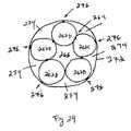
本発明の潅流バルーンは、相互に接触し、円形を形成するように配列される、複数の小型バルーンを約5つ有する。バルーンは、接触する線に沿って、相互に接合可能である。膨張流体は、5つのバルーンのそれぞれ内に分岐され、バルーンのそれぞれの近位端および遠位端で遮断される。5つのバルーン間の中心領域を使用して、血流の通路を提供する。本構造の支持は、1つのバルーンの次のバルーンへの接触に由来する。典型的サイズの大動脈弁のための内部血流潅流面積は、約0.4cm2であろう。The perfusion balloon of the present invention has about five small balloons arranged in contact with each other to form a circle. The balloons can be joined together along the line of contact. Inflation fluid is branched into each of the five balloons and blocked at each proximal and distal end of the balloon. The central area between the five balloons is used to provide a blood flow path. Support for this structure comes from the contact of one balloon with the next. The internal blood flow perfusion area for a typical size aortic valve will be about 0.4 cm2 .
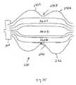
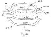
潅流バルーンの別の実施形態では、外側巻装が、5つの上述のバルーンの周囲に留置される。本外側巻装は、5つのバルーンをさらに接合または相互に付着するように保持する役割を果たすだけではなく、また、外側巻装と5つのバルーンとの間に区画を提供する。本外側区画は、流体からの内部圧に曝露され得、弁尖に拡張能力を提供するために使用可能である。外側区画は、所望に応じて、犬用の骨形状に形成可能であって、本開示に記載の他の実施形態の特性も、本外側犬用の骨形状のバルーン外側巻装またはカバーに適用可能である。また、外側巻装も、5つのバルーン間の中心領域に設置可能である。本外側巻装は、血液潅流のための流動導管路としての役割を果たし得、また、5つのバルーンのそれぞれに取着され、潅流バルーン構造全体に安定性を提供可能である。 In another embodiment of the perfusion balloon, an outer wrap is placed around the five aforementioned balloons. This outer wrap not only serves to hold the five balloons further bonded or attached to each other, but also provides a compartment between the outer wrap and the five balloons. This outer compartment can be exposed to internal pressure from the fluid and can be used to provide expansion capability to the leaflets. The outer compartment can be formed into a bone shape for dogs as desired, and the characteristics of other embodiments described in the present disclosure also apply to a bone-shaped balloon outer wrap or cover for this outer dog. Is possible. An outer wrap can also be installed in the central region between the five balloons. The outer wrap can serve as a flow conduit for blood perfusion and can be attached to each of the five balloons to provide stability to the entire perfusion balloon structure.
また、潅流バルーンを形成するための方法も記載される。形成ツールと、より大きい直径および小さい直径を有する、2つのバルーンと、を使用することによって、5つの個々のバルーンの均等物を形成可能である。より大きい直径のバルーンは、5つのバルーンのそれぞれの約外側半分を形成し、より小さいバルーンは、5つのバルーンのそれぞれの内側半分を形成する。1つのバルーン部分から別の部分への膨張流体の分岐は、バルーンの完全性を譲歩しない技術を使用して達成可能である。一時的弁中心潅流面積内に設置し、膨張手技の際、全身血圧が維持されることを確実にすることが可能である。 A method for forming a perfusion balloon is also described. By using a forming tool and two balloons with larger and smaller diameters, the equivalent of five individual balloons can be formed. The larger diameter balloon forms approximately the outer half of each of the five balloons, and the smaller balloon forms the inner half of each of the five balloons. The branching of inflation fluid from one balloon part to another can be achieved using techniques that do not compromise the integrity of the balloon. It can be placed within the temporary central valve perfusion area to ensure that systemic blood pressure is maintained during the inflation procedure.
本発明の実施形態が可能なこれらおよび他の側面、特徴、ならびに利点は、付随の図面を参照して、本発明の実施形態の以下の説明から明白かつ解明されるであろう。 These and other aspects, features, and advantages of embodiments of the present invention will be apparent and elucidated from the following description of embodiments of the present invention with reference to the accompanying drawings.
次に、本発明の特定の実施形態が、付随の図面を参照して記載される。しかしながら、本発明は、多くの異なる形態において具現化されてもよく、本明細書に記載の実施形態に限定されるものとして解釈されるべきではない。むしろ、これらの実施形態は、本開示が詳細かつ完全となり、発明の範囲を当業者に完全に伝えるように提供される。付随の図面に図示される実施形態の詳細な説明で使用される用語は、本発明を限定するものとして意図されない。図面中、同一番号は、同一要素を指す。 Specific embodiments of the present invention will now be described with reference to the accompanying drawings. However, the present invention may be embodied in many different forms and should not be construed as limited to the embodiments set forth herein. Rather, these embodiments are provided so that this disclosure will be thorough and complete, and will fully convey the scope of the invention to those skilled in the art. The terminology used in the detailed description of the embodiments illustrated in the accompanying drawings is not intended to be limiting of the invention. In the drawings, the same number indicates the same element.
別途規定されない限り、本明細書に使用される用語はすべて(技術および科学用語を含む)、本発明が属する当業者によって一般的に理解されるものと同一意味を有する。さらに、一般的に使用される辞書に定義されるもの等の用語は、関連技術の文脈における意味と一致する意味を有するものとして解釈されるべきであって、本明細書にそのように明示的に規定されない限り、理想的または過度に形式的意味として解釈されないことを理解されたい。 Unless otherwise defined, all terms used herein (including technical and scientific terms) have the same meaning as commonly understood by one of ordinary skill in the art to which this invention belongs. In addition, terms such as those defined in commonly used dictionaries should be construed as having a meaning consistent with the meaning in the context of the related art, and are expressly indicated herein as such. It should be understood that it is not to be construed as an ideal or unduly formal meaning unless otherwise specified.
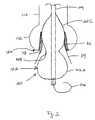
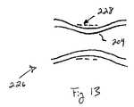
図1−4は、本発明による、非伸展性近位領域102Cと、非伸展性遠位領域102Aと、半伸展性胴部102Bと、を伴う、大動脈弁形成術用カテーテル100の好ましい実施形態を図示する。半伸展性胴部は、複数回の膨張後、その初期形状に復帰可能な伸縮性エラストマー材料から形成される。概して、これらの領域102A、102B、および102Cは、ある膨張圧において、犬用の骨または砂時計形状に膨張し、大動脈弁120内のバルーン102の所望の位置を達成するのを支援する。以下に詳述されるように、半伸展性胴部102Bは、弁120の弁輪118に対して、さらに展開可能であって、弁輪118のサイズ、したがって、適切な置換弁サイズをユーザが決定するのを支援する。 1-4 are preferred embodiments of an
弁形成術バルーン102は、好ましくは、カテーテル本体104の遠位端に配置され、ピグテール端ガイドワイヤ106を介して送達される。カテーテル本体104内の少なくとも1つの通路は、バルーン10と連通し、液体(または、随意にガス)によって膨張させる。 The
本弁形成術用カテーテル100は、米国特許出願公開第2005/0090846号(その内容は、参照することによって、本明細書に援用される)に記載される技術に従って、生成および使用可能であることを理解されたい。 The
動作時、本発明の弁形成術用カテーテル100は、Seldinger技術を使用して、大腿または上腕動脈を通して導入され、末梢血管内に血管シース導入器を留置する。代替として、本発明の弁形成術用カテーテルは、外科的肋間切開を介して、大動脈弁にわたって、経心尖的に順行性に留置可能である。経心尖部アプローチの場合、犬用の骨形状のバルーンの遠位球状部は、経大腿アプローチを使用する時のように、近位球状部ではなく、大動脈洞内に留置されるであろう。簡単にするため、さらなる説明はすべて、経大腿アプローチに関して行われる。しかしながら、種々の異なる留置手技が、本発明に従って可能であることを理解されたい。 In operation, the
経大腿アプローチに戻ると、ガイドワイヤは、大動脈弁にわたって留置され、弁形成術バルーンカテーテル100が、ピグテール106が左心室内に位置するように、ガイドワイヤを介して、逆行性に前進される。次に、蛍光透視法または他の撮像技術を使用して、バルーン102は、遠位部分102Aが左心室流出路114内に位置し、胴部102Bが弁輪118内に位置し、近位部分が大動脈洞112内の弁尖116に対して位置するように、弁120内に留置される。 Returning to the transfemoral approach, the guidewire is placed over the aortic valve and the
図2から最も良く分かるように、バルーン102は、約0.1〜0.5atm(すなわち、バルーン102内の圧力は、その外側の圧力約0.2atmより若干高い)の圧力まで膨張される。本圧力では、胴部102Bは、近位部分102Cおよび遠位部分102Aならびに弁輪118と比較して、顕著に小型サイズである。本小型サイズの胴部102Bは、「心合」または胴部102Bを弁輪118に位置付ける、したがって、バルーン102の全部分の所望の位置を達成するのを支援する。シリコーン油または親水性コーティング等の潤滑剤をバルーンの外表面に塗布し、本心合配向を向上させることが可能である。代替として、バルーンの一部の外表面をテクスチャ加工または粗面化し、膨張後、バルーンを定位置に保持するのを支援することが可能である。 As best seen in FIG. 2, the
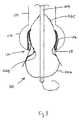
次に、バルーン102内の圧力は、さらに増加され、図3に示されるように、近位部分102Cのサイズを増大させ、弁尖の外側への押動を開始する。本圧力は、0.5〜5atm、好ましくは、1−2atmの範囲であり得る。近位部分102Cのサイズ増加は、弁尖116を押動して、開放させ、石灰化部分を破砕し、さらに、蝶着点を生成する。 Next, the pressure in the
また、胴部領域102Bは、本面積内の材料の伸展性質によって、上述の圧力において、直径が増加する。さらに、遠位部分102Aは、流出路内の解剖学的特徴の変動に応じて、サイズを幾分増大させてもよい。しかしながら、遠位部分102Aの展開は、最終的には、非伸展性材料構造によって制限される。血流は、短時間の間のみ遮断され得るため、バルーン102は、すぐに、急速に収縮される。 The diameter of the body region 102B increases at the above-described pressure due to the extension property of the material within this area. Furthermore, the distal portion 102A may increase in size somewhat in response to variations in anatomical features within the outflow tract. However, deployment of the distal portion 102A is ultimately limited by the non-extensible material structure. Since blood flow can only be blocked for a short time, the
弁尖116が許容量に「蝶着」されると、ユーザは、カテーテル100を使用して、内部拡張負荷に曝される時の弁輪118のサイズを評価し、したがって、移植するための置換弁の適切なサイズを決定可能である。以下の方法は、完全に伸張された弁輪118の直径を決定するのを支援するために記載される。 Once the
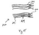
好ましくは、弁伸張直径を決定するために、バルーン102内の圧力は、図3に示されるものを超えて、図4のものまで、バルーン102を展開するように、再び増加される。造影剤が、撮像デバイス(例えば、蛍光透視法、X線等)に表示されるように、バルーン102内に注入される。胴部102Bは、半伸展性材料から構成されるため、さらなる圧力増加は、胴部102Bを外側に伸展させる。近位領域102Cおよび遠位領域102Aは、非伸展性材料によって構築されるため、これらの領域は、比較的に、同一直径のままである。圧力の増加に伴って、胴部102Bは、図4に見られるように、弁輪118に接触するまで、半径方向外側に伸展する。 Preferably, to determine the valve extension diameter, the pressure in the
胴部102Bが弁輪118に到達すると、弁120は、撮像可能となる。本撮像は、バルーン102内の造影剤、したがって、可視化および測定可能な胴部102Bの形状を図示する。代替として、放射線不透過性マーカが、蛍光透視撮像目的のために、胴部102Bに埋入または別様に設置されてもよい。 When the trunk portion 102B reaches the annulus 118, the
ユーザは、バルーン102内の圧力変化対バルーン容積変化、またはバルーン内への流体の注入容積率が、一定率で維持される場合、圧力変化対時間を監視することによって、胴部102Bが弁輪118に到達した時を決定するのを支援可能である。圧力計122または圧力変換器は、カテーテル100の近位端における膨張注入器と並列接続可能である。また、代替として、バルーン内またはその近傍に位置する、あるいはバルーンと流体連通する、圧力変換器が、圧力測定を提供可能である。圧力変換器は、所望に応じて、無線変換器であることが可能である。この場合、RF信号が、変換器から、バルーン内の圧力を示す、患者の身体外に位置する受信機に送信され得る。 When the pressure change in the
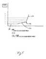
図5は、流体容積が一定率でバルーン内に注入されるのに伴って経時的に、またはバルーン容積に対して、例示的バルーン102内でどのように圧力が変化し得るかを示す、例示的グラフを図示する。最初に、バルーン102が、膨張するのに伴って、近位領域102Cおよび遠位領域102Aが、膨張して、胴部が、その平衡低圧力状態まで膨張する。これらの領域102Aおよび102Cは、非伸展性材料から構成されるため、バルーン102内の圧力は、非拘束バルーンが流体によって充填を開始するのに伴って、比較的に不変のままである(例えば、圧力勾配130は、比較的に平坦および低圧力である)。近位領域102Cおよび遠位領域102Aが、その非伸展性展開の限度に到達するのに伴って、バルーン内の圧力は、増加を開始し(例えば、圧力勾配132を比較的に増加する)、胴部102Bをその平衡低圧力状態を超えて展開させる。胴部102Bの展開の際の本圧力変化は、概して、胴部102Bが弁輪118に接触し、胴部102Bのさらなる展開を著しく制限するまで、胴部材料の伸展性を示す、低上方勾配132を辿る。したがって、弁輪118は、圧力対相対または絶対バルーン容積曲線内に変曲点133を生じさせ、弁輪および胴部の伸展性を示す、勾配134の増加が続く。バルーンの絶対容積は、一定容積ポンプによって制御され、バルーン内に注入される絶対容積を追跡するように監視可能である。代替として、一定容積ポンプを使用して、バルーン内に注入される流体の相対容積を制御可能であって、相対容積変化は、バルーン圧の相対変化に対してプロット可能である。流体が、一定率でバルーン内に注入される場合、図4の勾配の場合の勾配134は、胴部の弁輪との接触が行われた後の圧力変化対時間を表すことが可能である。 FIG. 5 illustrates an example of how pressure may change in the
医師または操作者は、弁輪に適用される制御された力の印加によって、制御下で弁形成術手技を提供する、本発明に伴う能力を有する。バルーン胴部が、弁輪と接触するのに伴って、図5に示されるように、圧力曲線の変曲点または勾配変化が、観察される。本点では、胴部内の圧力は、胴部の収縮力によって平衡化され、弁輪には、ほとんど力が印加されない。医師または操作者は、バルーン内の圧力を継続して増加させ、それによって、変曲点圧力を上回る本漸増圧力のみ弁輪に印加可能である。本漸増圧力のみ、弁輪に印加されるため、弁輪は、大規模な力に曝露される場合に生じ得る、解離に対して保護される。また、変曲点を上回る圧力曲線の勾配は、弁輪がより軟性の弁輪であるか、または硬く、石灰化しているかどうかを示す。したがって、医師または操作者は、変曲点を上回る圧力曲線の勾配を観察することによって、弁輪の有効弾性率を査定可能である。 The physician or operator has the ability associated with the present invention to provide an angioplasty procedure under control by the application of a controlled force applied to the annulus. As the balloon body contacts the annulus, an inflection point or gradient change in the pressure curve is observed, as shown in FIG. At this point, the pressure in the body is balanced by the contraction force of the body, and almost no force is applied to the annulus. The physician or operator can continuously increase the pressure in the balloon so that only this incremental pressure above the inflection point pressure can be applied to the annulus. Since only this incremental pressure is applied to the annulus, the annulus is protected against dissociation that can occur when exposed to large forces. Also, the slope of the pressure curve above the inflection point indicates whether the annulus is a softer annulus or is hard and calcified. Accordingly, the physician or operator can assess the effective elastic modulus of the annulus by observing the slope of the pressure curve above the inflection point.
この点において、ユーザが、圧力の勾配が勾配132に類似する勾配から勾配134に変化(すなわち、変曲点133)すると決定すると、胴部102Bは、弁輪118に接触した可能性がある。その時点で、ユーザは、上述のように、弁120を撮像し、弁輪径を決定可能である。代替として、ユーザまたは製造者は、手技に先立って、異なる圧力において、バルーン102の胴部102Bのサイズを決定してもよい。したがって、ユーザは、変曲点133に対する圧力示度数を確認し、胴部102Bのサイズを評価可能である。 At this point, if the user determines that the pressure gradient changes from a gradient similar to
好ましくは、コンピュータおよびコンピュータソフトウェア(例えば、特殊圧力ディスプレイデバイスまたはPC)を使用して、グラフの形式で、圧力を記録および表示可能である。ユーザは、グラフを監視し、変曲点133、したがって、弁輪のサイズを手動で決定可能である。代替として、コンピュータソフトウェアは、圧力データ(例えば、勾配)を監視し、変曲点133を自動的に決定し、その圧力値を直径サイズに変換してもよい。 Preferably, the pressure can be recorded and displayed in the form of a graph using a computer and computer software (eg, a special pressure display device or PC). The user can monitor the graph and manually determine the
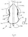
図6は、同様に、弁の弁輪118の直径を測定可能な、大動脈弁形成術用カテーテル142の別の好ましい実施形態を図示する。概して、弁形成術用カテーテル142は、図1−4に示されるカテーテル100に類似する。センサ144は、バルーン102の胴部102Bまたはその周囲に位置し、展開を測定する。 FIG. 6 also illustrates another preferred embodiment of an
例えば、センサ144は、図6に示されるように、胴部領域102Bまたは胴部領域の一部の周囲のリングに形成される、絶縁材料を含んでもよい。胴部102Bの伸張に応じて、材料の抵抗は、変化し、電気抵抗の変化を監視する回路を使用して、検出可能である。別の実施例では、センサ144は、材料が可変度に伸張するように付勢されるのに伴って、電気信号が発生され得るように、胴部の一部の周囲に位置する、圧電材料であってもよい。 For example, the
これらの上述のセンサ144のいずれも、好ましくは、バルーンのシャフト104に沿って位置する、電気ワイヤ146に接続され、バルーン102からバルーンカテーテル140の近位端およびバルーンカテーテルに取着される膨張デバイスに信号を送達する。 Any of these above-mentioned
別の実施例では、センサ144は、別のセンサに対する一方のセンサの近接度を検出し、2つのそのようなセンサ間の分離の変化を識別可能な、容量結合または誘導結合されたセンサのいずれかを含んでもよい。より具体的には、センサの構成要素は、バルーン胴部102Bおよびシャフト104上の胴部102Bの直径内の両方に設置されてもよい。故に、胴部102Bが展開するのに伴って、センサの構成要素は、相互から離れるように移動し、したがって、測定可能である。 In another embodiment,
さらに別の実施例では、超音波センサ142を使用して、弁輪に接触するのに伴って(例えば、圧力対容積曲線の勾配における変曲点133によって立証されるように)、胴部102Bの直径を測定可能である。小型超音波センサ142は、カテーテルシャフト104に沿って、バルーンの内部に設置される。そのような超音波センサは、周囲構造径を測定するために、介入バルーンカテーテルおよび他の診断デバイス内で使用される。次いで、変曲点133の際、これらのセンサ142によって測定される直径は、弁輪118の直径を示す。また、超音波センサ142は、弁輪の周縁を識別可能であってもよく、本情報は、弁輪径に変換可能である。 In yet another embodiment, the
好ましい実施形態では、遠位部分102Aは、約0.3−1atmにおいて、最大所定直径を達成する。近位部分102Cは、約0.5−2atmにおいて、圧力によって、弁尖が外側に変位されると、その最大所定直径を達成する。好ましくは、カテーテル100(または、カテーテル140)は、周知の拡張バルーン材料によって安全に含有されたままであるように、約3−5atmの圧力を超えないように構成される。 In a preferred embodiment, the distal portion 102A achieves a maximum predetermined diameter at about 0.3-1 atm. The
バルーン102内の所望の圧力限度(例えば、3−5atm)は、図7に示される(本明細書のいずれかに記載される)、膨張デバイス150によって達成可能である。例えば、バルーン膨張デバイス内に含有される、遮断安全弁または圧力溢流弁は、所望の最大圧力で作動可能である。 A desired pressure limit (e.g., 3-5 atm) within the
一バルーン実施形態では、胴部102Bは、膨張されると、楕円形状をとり、弁輪118の略非円形弁断面に良好に係合する。胴部102Bは、弁輪と接触するのに伴って、弁輪を円唇状にする、または弁輪が円唇状になるのに伴って、弁輪に対して外方力を印加することが可能である。しかしながら、半伸展性胴部102Bは、外方作用内部圧を平衡化するように作用する、内方収縮力を提供するため、胴部によって弁輪に外側に印加される力は、バルーンの内部圧未満である。圧また、内部バルーン全体は、弁尖を洞領域内に外側に押動させるように作用する。 In one balloon embodiment, the torso 102B, when inflated, takes an oval shape and better engages the generally non-circular valve cross section of the annulus 118. The body portion 102B applies an outward force to the annulus as the annulus becomes a lip shape as it comes into contact with the annulus, or as the annulus becomes a lip shape. Is possible. However, the semi-extensible body 102B provides an inward contraction force that acts to balance the outward acting internal pressure, so that the force applied to the annulus by the torso is internal to the balloon. Less than pressure. Also, the entire inner balloon acts to push the leaflets outward into the sinus region.
好ましくは、近位領域102Cは、上行大動脈110に隣接して位置する、大動脈洞112と同様にサイズ決定されるが、若干小さい膨張径を有する。近位球根状領域102Cの本直径サイズは、弁尖116に対して、より大きな歪曲を提供し、それによって、標準的円筒形形状のバルーンによって達成され得るものより効果的に、カルシウム堆積を破砕する。 Preferably,
代替として、バルーン102は、流体の指定容積が、その内部に収容されると、胴部径が、それに正比例して把握されるように、構築可能である。したがって、バルーン内に送達される膨張流体の容積を制御および把握するとともに、バルーン内の圧力を監視することによって、胴部が弁輪と接触すると(圧力を監視し、変曲点に留意することによって)、胴部径が決定可能となる(容積を把握することによって)。注入器等の容積式流体送達デバイスを使用して、バルーンに送達される流体の容積を査定可能である。図5に類似する圧力グラフは、監視目的のために作成可能であって、y−軸は、同様に、バルーン圧を示すが、x−軸は、膨張流体が一定率で送達される場合に送達される相対容積ではなく、バルーンに送達される絶対容積を表す。 Alternatively, the
図7は、本発明による、弁形成術バルーン100に造影剤を送達するために使用される、膨張ツール150を図示する。ハンドル152の圧縮は、プランジャ160にバレル152を下方に駆動させ、弁形成術用カテーテル171内に造影剤を付勢する。降下されたプランジャ160が停止部166に近づくのに伴って、造影剤は、2段階プロセスで駆動される。 FIG. 7 illustrates an
第1の段階では、造影剤は、流出ポート182から高速で進行し、約1−5秒以内に、そのバルーン容積内の約90%によって、バルーン100を充填する。次いで、第2の段階では、上方プランジャは、側孔178を通る流体抵抗によって制限される制御速度において、下方プランジャ内に位置する孔178を通して、約1−2ccの残留流体を駆動させる。 In the first stage, the contrast agent travels at high speed from the
バルーン100から流体を除去するために、トグルスイッチ158が作動され、ハンドル152の圧縮によって、下方ではなく、プランジャを上方に付勢し、真空を生成し、下方プランジャ180内に位置する一方向弁168を通して、造影剤を急速に除去させる。下方プランジャ180は、停止部166と接触し、バルーンへの次の流体の送達のための準備ができるまで、真空力から上方に上昇する。 To remove fluid from the
可変抵抗器156は、流体容積測定器としての役割を果たし、バルーン100に対する流体送達の相対量(または、送達される容積変化)を追跡する。また、他のデジタル位置センサを使用して、送達デバイスのバレルに対するプランジャの相対移動を検出可能である。バレル内の流体容積を検出するセンサは、膨張デバイス、バルーンカテーテル、または患者の身体外に位置する別個の部材上に位置する、ディスプレイ164に電気信号を送信する。 The
バルーン圧変換器184は、カテーテルシャフト104との接点近傍のバルーン100内に設置される。また、バレル圧力変換器172は、慣性およびシャフト伸展性による、バルーン圧変動を考慮するために、送達デバイスまたは膨張ツールのバレル162内に設置される。圧力変換器のうちの1つのみ、必要とされ、圧力示度数がバルーン圧の正確な測定値であることを確実にしてもよい。バルーン圧および相対バルーン容積を表す、圧力示度数は、読み出しディスプレイ164によって検出される。読み出しディスプレイは、コンピュータチップとともに、電子回路を備え、圧力および相対バルーン容積信号を受信し、それらを記憶し、圧力対相対または絶対バルーン容積をプロットする。また、コンピュータチップは、圧力対容積曲線の勾配を算出し、本勾配変化を検出可能である。 The
圧力対容積曲線の勾配が、変曲点または勾配変化に到達すると、本検出された圧力は、コンピュータチップによって捕捉され、本圧力時のバルーンの直径とともに表示されるであろう。バルーンの直径は、コンピュータチップによって計算され、胴部領域の弾性率および変曲点時の圧力を反映するであろう。次いで、本胴部径は、読み出しディスプレイによって表示される、弁輪径を示すであろう。 When the slope of the pressure versus volume curve reaches an inflection point or slope change, the detected pressure will be captured by the computer chip and displayed along with the diameter of the balloon at the actual pressure. The balloon diameter is calculated by the computer chip and will reflect the elastic modulus of the torso region and the pressure at the inflection point. The barrel diameter will then indicate the annulus diameter displayed by the readout display.
また、膨張デバイスは、流体が、略一定率で、バルーンカテーテルに送達されるように、動作可能であることにさらに留意されたい。この場合、読み出しディスプレイ内に見出されるコンピュータチップは、圧力データを受信し、それをバルーン内への流体注入の開始からの経過時間に対して記憶するであろう。コンピュータチップは、本事例では、圧力対時間をプロットし、本曲線の勾配を算出し、本勾配における変化を検出するであろう。圧力対時間曲線の勾配が、変曲点に到達すると、本点における圧力が、コンピュータチップによって捕捉され、読み出しディスプレイによって表示される、胴部径示度数に変換される。 It is further noted that the inflation device is operable so that fluid is delivered to the balloon catheter at a substantially constant rate. In this case, the computer chip found in the readout display will receive the pressure data and store it for the elapsed time since the start of fluid injection into the balloon. The computer chip will in this case plot pressure versus time, calculate the slope of the curve and detect changes in the slope. When the slope of the pressure versus time curve reaches the inflection point, the pressure at this point is captured by the computer chip and converted to a barrel diameter reading that is displayed by the readout display.
好ましくは、バルーン102は、単一内部区画を備える。しかしながら、その独自の膨張内腔を伴う、複数の区画また、可能である。例えば、バルーン102は、近位区画と、中央胴部区画と、遠位区画と、を含み、それぞれ、個々の膨張制御を可能にしてもよい。 Preferably, the
バルーン102は、バルーンカテーテル内で使用するために、当技術分野において周知の種々の異なる材料から作製可能である。例えば、伸展性または半伸展性材料は、ナイロン、Surlyn、ビニル、PVC、ポリエチレン、ポリウレタン、Pebax、オレフィン、またはこれらの材料のコポリマーから選択可能である。別の実施例では、非伸展性材料は、PET(Dacron)、Teflon、ポリイミド、Kevlar巻装、金属、ポリマー、または繊維材料から選択可能である。さらなる実施例では、伸展性または半伸展性材料は、電子線、化学、または他の架橋処理等、架橋結合を適用することによって、比較的に非伸展性に作製可能である。さらに別の実施例では、非伸展性材料は、電子線、化学処理、または他のプロセスによって処理し、バルーン材料の分子構造を弱化させることによって、より伸展性あるいは半伸展性に作製可能である。
一実施形態では、バルーン102の外側に、手技の際、溶出させるための所望の薬物をコーティング可能である。例えば、オリムスまたはパクリタキセル系薬物が使用され得る、または他の種類の薬物は、カルシウムの局所堆積を消失させ、可能性として、骨芽細胞のカルシウム堆積を変質させる。 In one embodiment, the
上述のように、本発明のバルーンの実施形態は、異なる伸展性(例えば、非伸展性、半伸展性、および伸展性)の領域を有してもよい。これらの特性を伴うバルーンを生成するためのいくつかの例示的技術は、以下に詳述される。 As described above, balloon embodiments of the present invention may have regions of different extensibility (eg, non-extensibility, semi-extensibility, and extensibility). Some exemplary techniques for generating a balloon with these characteristics are detailed below.
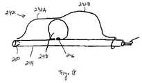
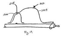
図8に示される一実施例では、バルーン200は、半伸展性材料の第1の管206および非伸展性材料の第2の管204を押出することによって、生成可能である。非伸展性管204の1つ以上の区分は、非伸展性にされる領域または複数の(例えば、近位区分102Cおよび遠位区分102A)内において、半伸展性管206上に同心円状に載置可能である。次いで、本管アセンブリは、バルーン200の外部形状を形成する、加熱された鋳型202内に載置される一方、また、管アセンブリの内側において、圧力が印加され、鋳型の輪郭との所望の接触を維持する。また、接着剤または薄いポリマー層が、同心管204と206との間に印加され(好ましくは、鋳造プロセスに先立って)、相互に対する接合を向上させることが可能である。 In one example shown in FIG. 8, the
加えて、軸方向に配向された繊維を、胴部領域にわたって接着または毎入し、バルーン200が圧力増加に曝露されるのに伴う、胴部の軸長増加を低減させのを支援可能である。軸方向繊維束は、胴部領域の外側に接着される、個々のポリマーまたは金属繊維束あるいは多繊維束であることが可能である。代替として、束は、バルーン材料の2つの層間に挟入可能である。 In addition, axially oriented fibers can be glued or inserted across the torso region to help reduce the torso axial length increase as
図9に見られる別の実施例では、バルーン208は、半伸展性材料を伴う内側管206と、非伸展性材料を伴う外側管204と、を有する、2つの管を共押出することによって生成可能である。外側非伸展性管204の一部は、半伸展性となることが所望される領域(例えば、胴部102B)内にエッチング可能である。好ましくは、レーザエッチング、プラズマエッチング、機械エッチング、または化学エッチングが使用される。非伸展性管204は、部分的にエッチングされ、または完全にエッチングされ、半伸展性管206を曝露させることが可能である。次に、共押出された管は、加熱された鋳型内に載置され、そこで、管内部の圧力によって、鋳型輪郭に対して、管を押圧し、所望の鋳造形状を形成する。代替として、共押出された管は、非伸展性材料204のエッチングに先立って、鋳造可能である。鋳造後、外側管は、所望の伸展性(または、非伸展性)をより正確に達成するための場所において、さらにエッチング可能である。 In another embodiment seen in FIG. 9, the
別の例示的構築方法では、非伸展性外側層は、半伸展性バルーン全体の外側に適用可能であって、胴部領域内に位置する軸方向細隙を胴部の外側非伸展性層内に形成し、内部圧の増加に曝露されると、半伸展性胴部の直径を拡大させることが可能である。 In another exemplary construction method, the non-extensible outer layer can be applied to the outside of the entire semi-extensible balloon and an axial slit located in the torso region is inserted into the outer non-extensible layer of the torso. When exposed to increased internal pressure, it is possible to increase the diameter of the semi-extensible body.
図10に見られるさらに別の実施例では、バルーン212は、半伸展性材料206を所望のバルーン形状に鋳造することによって生成可能である。半伸展性となることが所望される面積は、214によって、マスキングまたは被覆可能であって、薄い非伸展性ポリマー層216をマスキングされていない領域(例えば、バルーン102の遠位領域102Aおよび近位領域102C)内に適用可能である。そのような非伸展性材料は、ポリイミド、テレフタル酸ポリエチレン、繊維補強ポリマー、および非伸展性バルーンのために一般的に使用される多くのポリマーを含むことが可能である。好ましくは、非伸展性ポリマー216は、噴霧または浸漬コーティングによって適用可能であって、さらに処理され、架橋結合を提供し、非伸展特性を向上させることが可能である。バルーンの領域は、プロセスの種々の段階の際、マスキングされ、伸展性および非伸展性の種々のレベルまたは面積を提供可能である。 In yet another embodiment seen in FIG. 10, the
図11に見られるさらに別の実施例では、バルーン218は、非伸展性材料204を所望のバルーン形状に鋳造することによって生成可能である。次に、非伸展性材料204は、所望の面積(例えば、図1−4のバルーン102の胴部102Bとなるであろう面積)内において事後処理され、半伸展特性を達成可能である。本事後処理は、電子線、化学処理、または機械的処理を含んでもよい。より特定の実施例では、電子線は、大部分のフッ素ポリマー材料内の架橋結合を低減させ、したがって、処置された面積内の伸展性を増加させ得る。 In yet another embodiment seen in FIG. 11, the
図12に示される別の実施例では、バルーン222は、半伸展性材料206を所望のバルーン形状に鋳造することによって生成可能である。次に、半伸展性材料206は、所望の面積内において、事後処理され、非伸展特性を達成可能である。本事後処理は、、例えば、ポリエチレンに見られるような大部分の炭化水素骨格間の架橋結合を生じさせるための電子線を含むことが可能である。再び、マスク214を使用して、半伸展性であることが所望される面積の処理を防止可能である。 In another embodiment shown in FIG. 12, the
図13に見られるさらに別の実施例では、バルーン226は、非伸展性材料204を所望のバルーン形状に鋳造し、図6に示される半伸展性であることが所望される領域の周囲に弾性部材228を載置することによって生成可能である。弾性巻装は、好ましくは、非伸展性バルーン形状の本来の直径より小さい、本来の直径(すなわち、大部分または部分的に非伸張直径)を有する。弾性巻装204に隣接および近接する、非伸展性材料204は、使用の際、折重、屈曲、または襞化し、半伸展性展開を可能にするように付勢されてもよい。 In yet another embodiment seen in FIG. 13, the
さらに別の実施例では、バルーンは、埋入または別様にバルーンの軸長に沿って位置する、複数の円周方向繊維を伴う材料を鋳造することによって生成可能である。これらの繊維の間隔を増減することによって、伸展性は、それぞれ、増減可能である。加えて、繊維は、直径を増減させ、バルーンの伸展特性をさらに修正可能である。 In yet another embodiment, the balloon can be generated by casting or with a material with a plurality of circumferential fibers located along or otherwise along the axial length of the balloon. The extensibility can be increased or decreased by increasing or decreasing the distance between these fibers. In addition, the fibers can be increased or decreased in diameter to further modify the stretch properties of the balloon.
図14に見られる別の実施例では、バルーン230は、バルーン形状に鋳造される、半伸展性材料206によって生成可能である。非伸展性材料204は、バルーン形状に別個に鋳造される。遠位および近位部分は、非伸展性材料204から切り出され、半伸展性バルーン材料206の遠位および近位端上に載置される。圧力および温度おw鋳型内のバルーン230に印加し、層を融合させる、あるいはまた、接着剤またはポリマーを層間に適用し、接合を向上させることが可能である。 In another example seen in FIG. 14, the balloon 230 can be produced by a
図15に見られる別の実施例では、バルーン232は、半伸展性材料206を鋳造し、非伸展性材料204をバルーン形状に別個に鋳造することによって生成可能である。非伸展性材料204の中央胴部部分は、より伸展性領域234を生成するように弱化される。非伸展性材料204を半伸展性材料206上に載置し、バルーン232を鋳型内に戻し、上述のように、圧力および熱によって、材料204および206を融合させる。また、あるいは代替として、接着剤または類似接合が、材料204と206との間に使用されてもよい。 In another embodiment seen in FIG. 15, the balloon 232 can be produced by casting the
図16に示される別の実施形態では、バルーン326は、少なくとも、半伸展性胴部領域236Bを通して延在する、編組部材238によって形成される。編組は、多繊維束のテレフタル酸ポリエチレン、ポリエチレン、あるいは他のポリマーまたは薄い金属繊維束から構築可能である。編組は、UV硬化性アクリル、ポリウレタン、または他の接合剤を使用して、バルーンに接合可能である。編組は、胴部236Bの直径を拡大させる一方、胴部236Bの長さを縮小させるであろう。本平衡は、胴部236Bによる弁輪118との接触が行われるのに伴って、デルタ圧/デルタ容積曲線内の変曲点133をより顕著とさせるであろう。また、編組部材238は、胴部236Bの直径を過伸展させ、弁輪118に解離を生じさせないことを確実にすることが可能である。また、編組部材238は、直径を展開しないように、非伸展性領域236Aおよび236Bを保持し、それによって、変曲点133の観察を改善するのを支援可能である。胴部領域236B内の編組部材238の編組角度は、例えば、バルーン236の球根状端部領域236Aおよび236C内より軸方向に配向されてもよい。 In another embodiment shown in FIG. 16, the balloon 326 is formed by a
随意に、実質的に円周方向を有し、上限直径と略等しい直径を有する、第3の繊維が、約42−75度の軸に対して繊維角度を有する、標準的編組に編組可能である。第3の繊維の存在は、円周方向繊維束によって設定される上限直径を超えて伸展不可能であるように、編組の直径を制限し得る。 Optionally, the third fiber having a substantially circumferential direction and having a diameter approximately equal to the upper diameter can be braided into a standard braid having a fiber angle with respect to an axis of about 42-75 degrees. is there. The presence of the third fiber may limit the diameter of the braid so that it cannot extend beyond the upper limit diameter set by the circumferential fiber bundle.
別の実施形態では、編組部材は、さらに展開されないその構成において、バルーン上に接合可能である。好ましくは、本接合は、胴部が約18mmの直径まで展開されると、生じる。ここでは、編組は、編組の各端を引き裂くことによって、より小さい直径に付勢される。次いで、より小さい本直径部分は、胴部に接合される。さらに、編組は、バルーンのより大きい直径の非伸展性端部部分に接合される。 In another embodiment, the braided member can be joined onto the balloon in its undeployed configuration. Preferably, this joining occurs when the barrel is deployed to a diameter of about 18 mm. Here, the braid is biased to a smaller diameter by tearing each end of the braid. The smaller full diameter portion is then joined to the barrel. In addition, the braid is joined to the larger diameter non-extensible end portion of the balloon.
バルーンの一実施形態を形成するための代替方法は、0.0005−0.003インチ、好ましくは、0.001−0.002インチの直径範囲のPET、Dacron、ナイロン、または他の高強度材料の多繊維束からジグザグ形状を形成するステップを含む。多繊維繊維束の各超極細繊維は、直径約5−20ミクロンであり得る。また、類似寸法のニチノール多繊維または単繊維束も使用可能である。ジグザグ形状は、ジグザグ繊維束が付勢下で直線化されるのに伴って、胴部の直径変化18〜24mmに対して、平均軸方向から30−60度、好ましくは、40−50度の角度を有し得る。ジグザグ繊維束は、別の櫛状固定具の開口部との間に繊維束を付勢する、櫛状固定具に沿って、略直線繊維束を載置することによって形成される。同様に、横引きのこの歯を鋳型として使用して、繊維束を別の横引きのこの谷部内に付勢可能である。次いで、繊維束は、熱処理され、ジグザグパターンを形成する一方、固定具または鋳型によって保持される。 An alternative method for forming one embodiment of the balloon is PET, Dacron, nylon, or other high-strength material in the 0.0005-0.003 inch, preferably 0.001-0.002 inch diameter range. Forming a zigzag shape from the multiple fiber bundles. Each ultrafine fiber of the multifiber bundle can be about 5-20 microns in diameter. Nitinol multifilaments or single fiber bundles of similar dimensions can also be used. The zigzag shape is 30-60 degrees from the average axial direction, preferably 40-50 degrees with respect to a diameter change of 18 to 24 mm as the zigzag fiber bundle is linearized under bias. It can have an angle. A zigzag fiber bundle is formed by placing a substantially straight fiber bundle along a comb-like fixture that biases the fiber bundle between openings of another comb-like fixture. Similarly, this transverse tooth can be used as a mold to bias the fiber bundle into this valley of another transverse. The fiber bundle is then heat treated to form a zigzag pattern while being held by a fixture or mold.
より小さい直径構成におけるバルーンの場合、ジグザグ繊維束は、螺旋状に胴部領域(好ましくは、直径約18mmに膨張される)の周囲に巻着される。また、ジグザグ材料の円形状も使用可能であることに留意されたい。例えば、ジグザグ繊維束は、レーザを使用して、管またはニチノールから切り出され、バルーンの胴部の周囲に載置可能である。次いで、ジグザグ繊維束は、シリコーン、ポリウレタン、これらのポリマーのコポリマー、および他のポリマー等、エラストマー接着剤を使用して、胴部に接合される。 For balloons in smaller diameter configurations, zigzag fiber bundles are spirally wrapped around the barrel region (preferably inflated to a diameter of about 18 mm). It should also be noted that a circular shape of zigzag material can be used. For example, a zigzag fiber bundle can be cut from a tube or nitinol using a laser and placed around the body of the balloon. The zigzag fiber bundle is then joined to the barrel using an elastomeric adhesive such as silicone, polyurethane, copolymers of these polymers, and other polymers.
別の実施形態では、犬用の骨形状のバルーンは、PETまたはナイロン等の非伸展性材料から構成される、直径約25mmの円筒形バルーンによって形成可能である。胴部が位置するように意図される、本バルーンの中心領域では、非伸展性材料は、折重される。これは、まず、胴部領域内で軸方向に及ぶ波形または波状形状を有するようにバルーンを形成する、初期鋳型によって成され得る。代替として、各端部開口部からバルーン内側に金属要素を、そしてバルーン外側に鋳型を載置し、バルーン材料を波形または波状形状に付勢させることによって、事後処理として形成可能である。波状形状は、エラストマー胴部材料(上述)による収縮が予測される場合、制御された様式において、非伸展性バルーンを折重させるであろう。 In another embodiment, the dog-shaped balloon for dogs can be formed by a cylindrical balloon having a diameter of about 25 mm composed of a non-extensible material such as PET or nylon. In the central region of the balloon where the barrel is intended to be located, the non-extensible material is folded. This can be done by an initial mold that first forms the balloon to have an axial corrugation or wavy shape within the torso region. Alternatively, it can be formed as a post process by placing a metal element inside each balloon from each end opening and a mold outside the balloon and biasing the balloon material into a corrugated or wavy shape. The wavy shape will fold the non-extensible balloon in a controlled manner if shrinkage due to the elastomeric body material (described above) is expected.
第2のステップとして、エラストマー胴部は、胴部の中心における約18mmの小径から胴部の両端における約24mmの直径に伸展するように形成可能である。本構成要素は、鋳造操作または押出操作から形成可能であって、その後、適切な形状を形成あるいは鋳造するための事後処理方法が続く。材料は、シリコーン、ポリウレタン、コポリマー、または他のエラストマーポリマーであることが可能である。 As a second step, the elastomeric body can be formed to extend from a small diameter of about 18 mm at the center of the body to a diameter of about 24 mm at both ends of the body. The component can be formed from a casting or extrusion operation, followed by a post-processing method to form or cast the appropriate shape. The material can be silicone, polyurethane, copolymer, or other elastomeric polymer.
次いで、非伸展性バルーンは、0.1−4atmの範囲のより低い圧力で、その展開構成に展開される。次いで、胴部は、非伸展性バルーンの中心上に載置され、中心に接合される。圧力の解放に応じて、バルーンの胴部部分は、胴部部分の形状および力によって収縮する。より大きい圧力への展開に応じて、胴部領域内に位置する非伸展性バルーン材料によって、胴部が25mmを超えて展開不可能であることが確実となる。 The non-extensible balloon is then deployed into its deployed configuration at a lower pressure in the range of 0.1-4 atm. The barrel is then placed on the center of the non-extensible balloon and joined to the center. In response to the release of pressure, the body portion of the balloon contracts due to the shape and force of the body portion. In response to deployment to higher pressures, the non-extensible balloon material located in the barrel region ensures that the barrel cannot be deployed beyond 25 mm.
上述のように、バルーン102の胴部102B(図1−4)は、好ましくは、伸展性または半伸展性であって、これは、その直径が、膨張バルーン102内の圧力に応じて、近位部分102Cと遠位部分102Aとの間で異なることを意味する。言い換えると、非伸展性領域は、膨張の際、比較的に直径が一定のままであある一方、半伸展性領域は、圧力増加に伴って成長するであろう。例えば、胴部102Bは、その平衡状態において、直径16−20mmであって、直径19−25mmで弁輪に係合するように伸張可能であってもよいが、近位および遠位端は、約23−28mmの範囲の比較的に固定直径のままである。 As described above, the barrel 102B (FIGS. 1-4) of the
好ましくは、バルーン102の胴部102Bは、約3−5mmだけ、その平衡低圧状態において、「小型」(すなわち、弁輪と比較してより小さいサイズ)である。例えば、患者の弁120の標的弁輪118が、約23mmである場合、胴部102Bを伴うバルーン102は、平衡時、約20mmである。好ましくは、本例示的胴部102Bは、圧力2atmで2mmずつ、直径22mmまで成長する。本22mmの直径および内部圧2atm時、直径22mmに到達するのに、わずか2atmの圧力を要するため、弁輪に付与される外方力は、略ゼロである。本例示的バルーン102が、3atmまでさらに加圧されるのに伴って、その胴部102Bは、さらに23mmまで成長し、弁輪118の壁と接触し得るが、あったとしても、それほど弁輪118に圧力をかける可能性は低い(胴部102Bが接触係合し始めたばかりであるため)。 Preferably, the body 102B of the
対照的に、近位部分102Cおよび遠位部分102Aは、これらの部分102Aおよび102Cが非伸展性であって、平衡圧時にこれらの構造との接触が開始するため、弁尖116ならびに左心室流出路114に対して、約3atmの外方力を印加する。圧力が、4atmまでさらに増加される場合、最大1atmの外方力のみ、弁輪118に印加されることになるであろう。本実施例では、例えば、2atm以下の圧力への弁輪118の曝露は、解離(すなわち、損傷)をもたらさないと考えられる。実際の弁輪径が22mmであって、胴部が2atmで弁輪と接触する場合、弁輪は、内部バルーン圧が4atmである場合、2atmの圧力に曝露され得る。 In contrast, the
さらに、胴部102Bは、好ましくは、胴部118が、弁輪118上に自動的に位置するように、自己位置付けし、それによって、弁120の他の部分への損傷を回避する。例えば、バルーンの胴部102Bが、左心室流出路114内の下方に位置する場合、通常、洞112内に位置する、近位部分102Cは、弁輪114内に展開し、可能性として、解離を生じさせ得る。胴部102Bが、何らかの形で洞112内に位置する場合、膨張された胴部102は、その基部において、石灰化弁尖116を「破砕」可能な直径に達しないであろう。胴部102Bの長さは、弁輪118に適切なサイズであって、類似転帰を回避しなければならない。 Further, the barrel 102B is preferably self-positioned so that the barrel 118 is automatically positioned on the annulus 118, thereby avoiding damage to other parts of the
自己位置付けを補助するために、バルーン102の外側は、弁輪118上に位置する胴部102によって、所望に位置に「摺動」するその能力を向上させるように、潤滑性であることが可能である。代替として、バルーンの外側表面は、テクスチャ加工または粗面化され、膨張の際、バルーンを定位置に保持するのを支援可能である。 To assist in self-positioning, the outside of the
本明細書で使用される、非伸展性とは、比較的に弾性である材料を指すことに留意されたい。言い換えると、そのような材料は、適度な圧力の印加等、大部分の意図された状況下、ほとんどまたは全く伸張しない。本明細書で使用される、伸展性または半伸展性とは、少なくともある程度の弾性を含む材料を指す。言い換えると、そのような材料は、適度な圧力の印加等、大部分の意図された状況下、ほとんどまたは全く材料に損傷を伴わずに、伸張するであろう。また、胴部材料は、好ましくは、圧力が低下されると、その初期直径に戻るように、伸縮性であるべきである。 It should be noted that as used herein, non-extensible refers to a material that is relatively elastic. In other words, such materials will stretch little or no under most intended circumstances, such as the application of moderate pressure. As used herein, extensible or semi-extensible refers to a material that includes at least some elasticity. In other words, such materials will stretch with little or no damage to the material under most intended circumstances, such as the application of moderate pressure. Also, the barrel material should preferably be stretchable so that when the pressure is reduced, it returns to its initial diameter.
以下に提示される具体的バルーンの説明は弁輪径21〜24mmのサイズ範囲を網羅するように意図される、一バルーンサイズの実施例である。半伸展性の胴部と、非伸展性球根状端部領域と、を伴う、犬用の骨形状のバルーンである。本特定の実施例の目的のために、図1が、さらに参照されるであろう。 The specific balloon description presented below is an example of one balloon size intended to cover a size range of 21-24 mm in valve diameter. A bone-shaped balloon for dogs with a semi-extensible body and a non-extensible bulbous end region. For the purposes of this particular embodiment, reference will further be made to FIG.
バルーン102は、約40−80mm、好ましくは、50−70mmの長さ111を有する。領域102Aおよび102Cは、非伸展性である一方、領域102Bは、半伸展性である。バルーン102は、約4−5atmの作業圧を有する、すなわち、破裂圧力は、約6−7atmであって、好ましくは、軸方向の断裂方向を伴う。バルーン102の巻装外形は、約10−12Frであって、カテーテルシャフト104は、好ましくは、約9−12Frである。ガイドワイヤ内腔は、約0.036インチワイヤによるワイヤを介した技術のために構成される。バルーン胴部102Bは、0.1atmで軸長約5−10mmの時の長さ109と、その中心に約18−21mmの最大直径105と、を有する。好ましくは、各区分102Cおよび102Aは、約25−56mmの最大直径103および107を有する。 The
以下は、種々の圧力時のバルーン胴部102Bの例示的測定値である。 The following are exemplary measurements of balloon barrel 102B at various pressures.

バルーン端部は、各端部において4mmの外径で形成可能である。一実施例は、カテーテルシャフトおよびバルーンに内径約0.038×外径0.046の管を通し、0.035インチガイドワイヤの通過をもたらす。バルーンの遠位端は、ガイドワイヤの管に接合される。バルーンのある程度の長さの展開は、胴部の展開による圧力下で生じ得る。好ましくは、類似軸方向展開を伴うガイドワイヤ管をバルーンとして使用することによって、バルーンが、圧力下で展開されるのに伴って生じる、あらゆるバルーンの湾曲を低減させることが望ましいであろう。 The balloon ends can be formed with an outer diameter of 4 mm at each end. One example is to pass a tube with an inner diameter of about 0.038 x outer diameter 0.046 through the catheter shaft and balloon, resulting in the passage of a 0.035 inch guide wire. The distal end of the balloon is joined to a guidewire tube. A certain length of balloon deployment may occur under pressure due to the deployment of the barrel. Preferably, it would be desirable to reduce any balloon curvature that occurs as the balloon is deployed under pressure by using a guidewire tube with similar axial deployment as the balloon.
上述の実施例では、胴部は、圧力が、ゼロatmを上回る小圧力(すなわち、0.1atm)から4atmに増加するのに伴って、約18mm〜24mmの展開を受けることが示唆される。本胴部伸展性は、線形伸展性として記載される。しかしながら、大部分のエラストマーポリマーは、線形ではないため、胴部の中央は、2atmおよび4atmで生じる、2つの時点において、実施例に示される直径を達成することが望ましい。これらの2つの中央胴部径は、それぞれ、2atmおよび4atm時、21mmならびに24mmである。好ましくは、胴部の中央の直径は、21mmおよび24mmのデータ点を達成するために、その自然状態(すなわち、約ゼロ圧力時)において、18mmより小さい。 In the example described above, it is suggested that the barrel undergoes a deployment of about 18 mm to 24 mm as the pressure increases from a small pressure above zero atm (ie, 0.1 atm) to 4 atm. The main body extensibility is described as linear extensibility. However, since most elastomeric polymers are not linear, it is desirable to achieve the diameter shown in the examples at two points where the middle of the barrel occurs at 2 atm and 4 atm. These two central barrel diameters are 21 mm and 24 mm at 2 atm and 4 atm, respectively. Preferably, the central diameter of the barrel is less than 18 mm in its natural state (ie at about zero pressure) to achieve 21 mm and 24 mm data points.
いくつかの実施例では、半伸展性胴部は、非伸展性球根状端部に結合される。半伸展性材料の非伸展性材料との本接点は、破損をもたらし得る、断絶を発生させる可能性がある。小遷移領域は、本破損を低減させ得るが、そのような遷移は、全バルーン材料および設計に対して、適切ではない場合があることに留意されたい。遷移領域が必要である場合、遷移領域は、胴部内に形成され、それによって、胴部の軸長を図面上に列挙される5mm−10の軸長より幾分小さくすることが可能である。 In some embodiments, the semi-extensible body is coupled to the non-extensible bulbous end. This contact of the semi-extensible material with the non-extensible material can cause breaks that can result in breakage. Note that small transition regions may reduce this breakage, but such transitions may not be appropriate for all balloon materials and designs. If a transition region is required, the transition region is formed in the barrel, thereby allowing the barrel axial length to be somewhat smaller than the 5 mm-10 axial length listed on the drawing.
非伸展性球根状領域102Cおよび102Aは、1atm〜4atmにおいて、固定直径を維持するように意図される。非伸展性領域が、圧力の増加に伴って伸張する場合、バルーン圧を監視することによって、胴部の伸張を検出することは困難となり得る。したがって、球根状領域は、好ましくは、あらゆる円周方向伸張を抑止する材料から作製されるべきである。 Non-extensible
米国特許出願公開第2005/0090846号(その内容は、参照することによって、本願に既に援用されている)で論じられるように、非伸展性胴部と、半伸展性近位および遠位部分と、を含む、バルーンの代替実施形態が、本発明に従って、可能である。一実施例では、バルーンは、後述の特性を有し得るが、本バルーン実施形態は、図1−4の半伸展性胴部バルーンの場合に記載されたように、弁輪を測定する能力を有していないことを認識されたい。 As discussed in U.S. Patent Application Publication No. 2005/0090846, the contents of which are already incorporated herein by reference, non-extensible torso, semi-extensible proximal and distal portions Alternative embodiments of balloons are possible according to the present invention. In one example, the balloon may have the characteristics described below, but this balloon embodiment provides the ability to measure the annulus as described for the semi-extensible trunk balloon of FIGS. 1-4. Recognize that you do not have one.
バルーンは、非伸展性の胴部と、半伸展性の少なくとも1つの端部部分と、を含む。しかしながら、また、両端部領域が、半伸展性であってもよい。端部部分は、圧力下で展開可能であって、それによって、球根状近位部分に、内部バルーン圧に応じた量だけ弁尖を押し戻させる一方、胴部は、弁輪を過拡張させることは不可能である。 The balloon includes a non-extensible body and at least one end portion that is semi-extensible. However, both end regions may also be semi-extensible. The end portion is deployable under pressure, thereby causing the bulbous proximal portion to push back the leaflets by an amount corresponding to the internal balloon pressure, while the torso causes the annulus to overexpand. Is impossible.
約2atmの内部圧は、その平衡サイズを約10−20%超えて、バルーンの近位部分を外側に展開させ、バルーンの直径を約20mm〜24mmに伸展させることが可能である。バルーンは、胴部が球根状領域より約15−25%小さい、バルーン形状が上述のような球根状であるように構築可能である。代替として、バルーンは、1.5atmの圧力時、球根状端部より約10%だけ小さい胴部を伴う、略円筒形形状であることが可能である。胴部は、長さ1−10mmの範囲であることが可能である。 An internal pressure of about 2 atm can exceed its equilibrium size by about 10-20%, allowing the proximal portion of the balloon to deploy outward and the balloon diameter to extend from about 20 mm to 24 mm. The balloon can be constructed such that the barrel is about 15-25% smaller than the bulbous region and the balloon shape is bulbous as described above. Alternatively, the balloon can have a generally cylindrical shape with a barrel that is about 10% smaller than the bulbous end at a pressure of 1.5 atm. The barrel can be in the range of 1-10 mm in length.
バルーンは、半伸展性バルーンの胴部領域に、非伸展性材料、螺旋巻装、編組、または織布を適用し、胴部を非伸展性領域にすることによって、構築可能である。代替として、バルーン補強は、化学または他の架橋結合の手段を介して、胴部に適用可能である。 Balloons can be constructed by applying a non-extensible material, spiral wrap, braid, or woven fabric to the body region of a semi-extensible balloon, making the body a non-extensible region. Alternatively, balloon reinforcement can be applied to the barrel via chemical or other cross-linking means.
別の代替実施形態では、バルーン全体が、非伸展性材料から構成されてもよい。非伸展性胴部アプローチを伴う、犬用の骨形状のバルーンは、1mm以内の弁輪径の精密な予測を必要とし得、したがって、バルーン胴部は、本直径に合致するサイズであるべきである。一実施例では、犬用の骨形状のバルーンは、完全に非伸展性であるように生成され、1mmの弁輪径サイズ変動単位のバルーンサイズを提供する。 In another alternative embodiment, the entire balloon may be composed of a non-extensible material. A dog-bone shaped balloon with a non-extensible torso approach may require a precise prediction of the annulus diameter within 1 mm and therefore the balloon torso should be sized to match this diameter. is there. In one example, a dog-bone shaped balloon is created to be completely non-extensible, providing a balloon size of 1 mm valve ring size variation.
本全非伸展性バルーンは、3atmから10atmを上回る非常に高圧までの範囲の圧力で動作する。安全性は、胴部が成長しないことを確実にすることによって得られる。好ましくは、犬用の骨形状のバルーンは、弁輪118において、胴部を自己心合するために移動するように、潤滑性である。自己心合の失敗は、バルーンのより大きい部分を弁輪に位置付けることになり、それによって、弁輪を解離させ得る。 The all non-extensible balloon operates at pressures ranging from 3 atm to very high pressure above 10 atm. Safety is obtained by ensuring that the barrel does not grow. Preferably, the dog-shaped balloon for dogs is lubricious so that it moves in the annulus 118 to self-align the torso. The failure of self-alignment will position a larger portion of the balloon in the annulus, which can cause the annulus to dissociate.
別の実施形態では、犬用の骨形状のバルーンは、完全に半伸展性である。故に、本バルーン構成は、バルーンの球根状端部領域の成長を抑制しない。端部球根状領域は、バルーン内の圧力が増加するのに伴って、依然として、容積を成長させることが可能であるため、胴部が弁輪と接触すると観察される、圧力/容積曲線の変化は、他の記載される実施形態と同様に明白ではない。 In another embodiment, the dog bone shaped balloon is fully semi-extensible. Thus, the present balloon configuration does not inhibit the growth of the bulbous end region of the balloon. The end bulbous region is still able to grow in volume as the pressure in the balloon increases, so the change in pressure / volume curve observed when the barrel contacts the annulus Is not as obvious as the other described embodiments.
上述との差異の1つは、全非伸展性バルーンは、伸展性曲線が、弁輪の直径をサイズ決定するために使用され得ることである。胴部の弁輪との接触後、弁輪は、作動圧の増加によって、直径を増加させ得るが、胴部は、弁輪展開が有意とならないように、適宜サイズ決定されるであろう。洞およびバルーンの遠位部分は、圧力増加に伴って、比例的に増加を継続するであろう。バルーン胴部のために選択される直径は、弁輪に応力をかけない直径によって設定されるであろう。本半伸展性バルーンのための材料が、概して、より高い圧力が、膨張の際、胴部の弁輪との接触に先立って使用されるようなものである場合(すなわち、2−5atm超)、バルーン全体が、同一半伸展性構造から作製され得る。バルーン内の内部圧は、弁輪にほとんど力を付与しないであろう。安全性は、弁輪径が、弁尖展開の際、胴部より大きく、膨張が、胴部の弁輪との接触直後に終了されることを確実にすることによって得られる。完全半伸展性バルーンに伴う、いくつかの動作上の困難点は、胴部が弁輪と接触後のバルーンの球根状部分の継続展開によって生じ得、それによって、変曲点後の圧力対容積曲線の勾配変化の規模を縮小させる。 One difference from the above is that for non-extensible balloons, the extensibility curve can be used to size the annulus diameter. After contact with the annulus of the body, the annulus may increase in diameter by increasing the operating pressure, but the body will be appropriately sized so that annulus deployment is not significant. The sinus and the distal portion of the balloon will continue to increase proportionally with increasing pressure. The diameter selected for the balloon body will be set by the diameter that does not stress the annulus. The material for the semi-extensible balloon is generally such that higher pressure is used prior to contact with the annulus of the trunk during inflation (ie, greater than 2-5 atm). The entire balloon can be made from the same semi-extensible structure. The internal pressure in the balloon will exert little force on the annulus. Safety is obtained by ensuring that the annulus diameter is larger than the body when the leaflet is deployed, and that the expansion is terminated immediately after contact with the annulus of the body. Some operational difficulties associated with a fully semi-extensible balloon can arise from the continued deployment of the bulbous portion of the balloon after the barrel contacts the annulus, thereby increasing the pressure versus volume after the inflection point. Reduce the magnitude of the curve slope change.
上述の全非伸展性バルーンと同様に、バルーンは、潤滑性であって、弁輪上に自己心合されることを確実にしてもよい。自己心合しない場合、弁輪領域内におけるバルーンの近位または遠位部分の留置によって、弁輪の解離を容易に生じさせ得る。本より高い圧力の半伸展性バルーンは、ナイロンまたは他の半伸展性材料から製造されてもよく、あるいは外形が制限要因では無い場合、バルーン壁内に接合もしくは含有される、編組または他の繊維基質を有する合成壁構造を有してもよい。 Similar to the all non-extensible balloon described above, the balloon may be lubricious and ensure that it is self-centered on the annulus. If not self-centering, dissociation of the annulus can easily occur by placement of the proximal or distal portion of the balloon within the annulus region. Higher pressure semi-extensible balloons may be manufactured from nylon or other semi-extensible materials, or braids or other fibers that are joined or contained within the balloon wall if the outer shape is not a limiting factor It may have a synthetic wall structure with a substrate.
図17および18は、本発明による、弁形成術バルーン242の別の実施形態を図示する。本バルーン242は、弁尖に対して展開するためのより大きい直径領域242Bと、左心室流出路内に係留するためのより小さい直径領域242Aと、を含む。患者の弁輪のサイズは、カテーテルシャフト244の膨張ポート248上に位置し、かつバルーン242内に位置する、より小さい内側バルーン248によって測定可能である。 17 and 18 illustrate another embodiment of an
内側バルーン248は、ポート246に接続し、内側バルーン248を最初に膨張させる、内側バルーン膨張内腔を有し、本バルーンを大動脈弁輪の上流および隣接して設置する、位置付けバルーンとしての役割を果たす。内側バルーンは、シャフトに接合され、バルーンの最良の位置付けを可能にする、形状または外形を得ることが可能である。本バルーンが定位置に来ると、より大きい外側バルーンが、別個の外側バルーン膨張内腔を使用して膨張され、外側バルーン242の洞部分を介して、弁尖を膨張させることが可能である。
外側バルーンの本洞部分242Bは、位置決めバルーン248より大きい直径を有し、大動脈弁尖を大動脈洞内で外側に押動させるようにサイズ決定される。外側バルーンは、図17および18に見られるように、円筒形の遠位形状を有することが可能であって、バルーン250は、内側バルーン248に追随する、近位端250Bおよび遠位端250Aを伴う、またはバルーン252は、図20に見られるように、胴部領域252Cを形成する、球根状近位端252Bおよび球根状遠位LVOT部分252Aを有する。 The outer balloon main sinus portion 242B has a larger diameter than the
図17−20の実施形態の外側バルーンは、非伸展性、半伸展性、または両方の材料の組み合わせを含む、上述の実施形態に記載される構築手段のいずれかを使用して、構築可能である。外側バルーンは、例えば、半伸展性胴部を有し、上述のように、弁輪径を測定するために使用可能である。 The outer balloon of the embodiment of FIGS. 17-20 can be constructed using any of the construction means described in the above embodiments, including non-extensible, semi-extensible, or a combination of both materials. is there. The outer balloon has, for example, a semi-extensible body and can be used to measure the annulus diameter as described above.
内側バルーンは、半伸展性または非伸展性材料のいずれかから構築可能である。また、内側バルーンを使用して、本明細書で上述のように、その容積を監視し、弁輪の直径を計算することによって、弁輪の直径を査定可能である。また、内側バルーンまたは内側と外側バルーンとの間のいずれかで行われる圧力測定は、上述のように、圧力変化対容積変化を監視し、弁輪との接触を識別するために使用可能である。超音波、圧電、電気抵抗、およびその他等の種々のセンサが、上述の実施形態に記載のように、弁輪径を測定するために、本実施形態と併用可能である。 The inner balloon can be constructed from either semi-extensible or non-extensible material. An annulus balloon can also be used to assess the annulus diameter by monitoring its volume and calculating the annulus diameter as described herein above. Also, pressure measurements made either on the inner balloon or between the inner and outer balloons can be used to monitor pressure changes versus volume changes and identify contact with the annulus, as described above. . Various sensors such as ultrasonic, piezoelectric, electrical resistance, and others can be used with this embodiment to measure the annulus diameter as described in the above embodiments.
治療目的のために、上述の実施形態のいずれかの外側に、薬物が塗布されてもよいことを理解されたい。例えば、「オリムス」または「パクリタキセル」群に類似する薬物を使用して、カルシウムの局所堆積を消失させ、可能性として、骨芽細胞のカルシウム堆積を変質させてもよい。 It should be understood that a drug may be applied outside of any of the above embodiments for therapeutic purposes. For example, drugs similar to the “Olimus” or “paclitaxel” group may be used to abolish local deposition of calcium and potentially alter the calcium deposition of osteoblasts.
また、手技の際、灌流を可能にするように、バルーン102の形状を構成することも可能である。例えば、潅流チャネルまたは通路が、バルーン102内に含まれてもよい。 It is also possible to configure the shape of the
図21および22は、5つの個々のバルーン262A−Eまたは流動面積266の周囲において5角形形状に配列される5つのバルーン区画を含む、潅流バルーンデバイス260を図示する。バルーン262A−Eはそれぞれ、取着部位264において、相互に取着される。各バルーン262は、2つの他のバルーン262と密接することによって、中心流動面積266に支持を提供する。5つのバルーン262のための中心流動面積266は、好ましくは、約0.48cm2であって、バルーン262が膨張される間、脳に適切な潅流を維持するのに十分であると考えられる。また、より少ない数のバルーンも使用可能であるが、しかしながら、これは、より小さい中心流動面積をもたらす。3つのバルーンが使用される場合、面積は、好ましくは、約0.056cm2であって、4つのバルーンの場合、好ましくは、約0.237cm2である。形状は、より少ない数のバルーンの方が安定するが、しかしながら、流動面積は、遥かに小さい。5つを超えるバルーン262が使用される場合、流動面積は、増大し得るが、しかしながら、形状の安定性は、低減され得る。21 and 22 illustrate a
各バルーン262は、バルーン262すべてが、同時に膨張されるように、バルーン262の近位端において、中心分岐管268に取着される。血流は、遠位端におけるバルーン262との間のアクセスを介して提供され、中心流動面積266を下方に流動し、近位端におけるバルーン262との間を通過する。5つのバルーン262は、バルーン流入口が、示されるように、アセンブリの中心軸に位置するのではなく、アセンブリの片側にずれて位置するように形成可能であることに留意されたい。膨張流入口および分岐管を中心軸からずらして設置することは、潜在的に、アセンブリ内へおよびそこからの血液のより直接的流路を可能にするであろう。 Each balloon 262 is attached to a
図23および24は、5つのバルーン262の外側の周囲における外側巻装272の追加を除き、上述のデバイス260に類似する、バルーン弁形成術デバイス270を図示する。外側巻装277は、また、5つのバルーン272の外側の周囲のバルーンとしての役割も果たす、薄いが、強固なプラスチック材料である。また、外側巻装272は、取着部位276において、好ましくは、5つのバルーン262に取着可能である。血液等の流体の流動は、5つのバルーン262間に位置する中心領域273を通して生じ得る。 FIGS. 23 and 24 illustrate a
バルーン262の外側巻装272への取着は、本バルーンアセンブリ270の形状に安定を提供するだけではなく、また、外部空間への別個の流入口内腔275を介して、274と標識された外部空間内のバルーンの外側のバルーンのそれぞれの間で膨張を生じさせる。外側巻装圧における外部空間274の展開は、構造全体に、外部組織に対する展開を提供し、円唇または連続形状を形成させる。外側巻装圧は、本外側巻装に均等支持を提供するように、バルーン膨張圧より幾分低くあるべきであると考えられる。外側巻装内の圧力は、好ましくは、1〜6atm、好ましくは、2〜5atmの範囲である。5つのバルーン内の圧力は、2〜20atmの範囲であってもよい。 Attachment of the balloon 262 to the
外側巻装と個々のバルーン262のそれぞれとの間を密閉し、バルーンアセンブリ270の中心流動面積266を通る灌流血液のための流動面積266から分離しなければならない。本流動通路は、バルーンアセンブリ270の近位および遠位端に提供され、5つのバルーン262のそれぞれとの取着を含まなければならない。血液のための連続通路は、中心流動面積266から、バルーンアセンブリの近位および遠位端における外側巻装に独立して密閉される、少なくとも2つのバルーンの間に位置する空間を通して形成される。 A seal between the outer wrap and each individual balloon 262 must be sealed and separated from the
図25は、5つの個々のバルーン262から形成される、上述のバルーン270に類似するが、ダンベルまたは小葉形状を有する、外側巻装272をさらに有する、バルーン280を図示する。近位球根状領域272Cは、洞領域に対する展開を提供し、遠位球状部272Aは、軸方向に移動せず、代わりに、大動脈起始部の弁輪に位置するバルーン胴部272Bと自己心合する傾向となるように、バルーンアセンブリに位置付けのための支持を提供する。バルーンアセンブリ280の機能性は、図1−4に記載のものと類似する。全体形状を向上させるために、胴部領域272Bは、取着点282において、バルーンのそれぞれに取着可能である。 FIG. 25 illustrates a
図26および27は、上述のデバイス270に類似するが、バルーンアセンブリ290内の通路292を形成する、付加的巻装または管を伴う、弁形成術バルーンデバイス290を図示する。内部通路292は、バルーンアセンブリ290の中心部分を通る血液のための閉鎖された流動空間を提供する。内部通路292は、中心流動面積から外側巻装272を通る血液の通過を可能にし、外側巻装272に、血液のための流動面積と別の連続空間を形成させる。内部通路292は、バルーンアセンブリの近位および遠位端において、外側巻装との密閉294を形成する。 FIGS. 26 and 27 illustrate an
図21−27に記載の潅流バルーンは、相互に隣接して位置し、その周囲に載置される外側巻装を有する、5つの別個のバルーンから形成可能である。膨張流体の分岐は、種々の方法において達成可能であって、その1つは、図21に示される。また、他の方法において、バルーンアセンブリを形成し、流体の分岐を達成することも可能である。 The perfusion balloon described in FIGS. 21-27 can be formed from five separate balloons that are located adjacent to each other and have an outer wrap mounted thereon. The branching of the inflation fluid can be achieved in various ways, one of which is shown in FIG. In other methods, a balloon assembly can be formed to achieve fluid branching.
5つのバルーンは、上述のように、相互に隣接して設置可能であって、バルーン間の直接開口部は、1つのバルーンから別のバルーンへの膨張流体のアクセスを可能にする。そのような開口部は、バルーンに接続可能であって、したがって、5つのバルーンのそれぞれへの膨張流体を分岐させる。バルーンの端部は、平坦化または折重され、密閉可能である。 Five balloons can be placed adjacent to each other, as described above, and the direct opening between the balloons allows access to inflation fluid from one balloon to another. Such an opening is connectable to the balloons and thus diverts the inflation fluid to each of the five balloons. The end of the balloon is flattened or folded and can be sealed.
相互に隣接して位置する、複数のバルーン型円筒形形状を有するバルーンアセンブリは、複数の円筒形形状の内側半分および外側半分を形成する、2つの円筒形管から形成可能である。図28に示されるように、5つの内部円筒形バルーンと、3つの円筒形バルーンから成る外側巻装と、を有する、バルーンアセンブリ300を形成可能である。外側バルーン半分302は、薄壁円筒形管であって、その周縁は、相互に隣接する5つのバルーン型円筒形形状のそれぞれの外側半分の付加的周縁に等しい。内側バルーン半分304は、外側バルーン半分より幾分小さく、5つのバルーン円筒形形状のそれぞれの内側半分を形成するために使用可能である。 A balloon assembly having a plurality of balloon-shaped cylindrical shapes located adjacent to each other can be formed from two cylindrical tubes that form an inner half and an outer half of the plurality of cylindrical shapes. As shown in FIG. 28, a
さらに、図28は、どのように内側304および外側バルーン半分302が、5つの隣接するバルーン型円筒形形状を効果的に形成するように設置される様子を示す。内側形成ツール308および外側形成ツール306が、図29に示されるように載置される。熱または他の接合方法を使用して、表面の内側/外側取着点において、内側および外側バルーン半分302ならびに304をともに取着する。開口部310が、膨張流体に対して通路を提供することが必要なバルーン接触領域では、非漏出開口部が、1つの区画から隣接する区画への本密閉内に作製され得るように、表面接触密閉を形成可能である。 Further, FIG. 28 shows how the inner 304 and
外側巻装が、上述のように、外側バルーン半分の周囲に密閉可能である。 The outer wrap can be sealed around the outer balloon half, as described above.
外側巻装は、弁形成術を含む、その種々の用途に対する必要に応じて、円筒形形状あるいは二小葉またはダンベル形状を有することが可能である。材料は、非伸展性、半伸展性、または非伸展性および半伸展性の組み合わせであることが可能である。一実施形態では、胴部領域は、半伸展性材料から形成され、球根状領域はそれぞれ、非伸展性であることが可能である。代替として、外側巻装全体が、非伸展性または半伸展性材料のいずれかから形成可能である。 The outer wrap can have a cylindrical shape or a bilobal or dumbbell shape as required for its various applications, including valvuloplasty. The material can be non-extensible, semi-extensible, or a combination of non-extensible and semi-extensible. In one embodiment, the torso region is formed from a semi-extensible material and each bulbous region can be non-extensible. Alternatively, the entire outer wrap can be formed from either non-extensible or semi-extensible material.
上述の潅流バルーンは、内部流動面積内で血液を流動させながら、長時間、大動脈弁尖の拡張が可能である。拡張時間の増加は、弁尖に粘弾性クリープを受けさせ、組織内に割裂を生じさせ、長時間膨張時間の利点が無い場合よりも弁のための流動面積を大きくさせ得る。流動面積の増加は、弁形成術手技のために、より大きな耐久性を可能にし得る。 The above-described perfusion balloon can expand the aortic leaflet for a long time while allowing blood to flow within the internal flow area. Increasing the expansion time can cause the leaflets to undergo viscoelastic creep, split in the tissue, and increase the flow area for the valve than if there is no advantage of extended expansion time. Increased flow area may allow greater durability for an angioplasty procedure.
また、弁形成術手技の際に灌流を提供する利点は、通常、10−15秒間のみバルーン膨張可能な標準的弁形成術手技によっては不可能である、他の療法効果を可能にし得る。例えば、凍結形成術は、脚部のアテローム性動脈硬化疾患の治療に対して、大きな成功を収めている。本明細書に提示されるバルーンアセンブリによる凍結療法の適用は、潜在的に、より大きな耐久性を提供可能な、弁尖割裂または再構成の向上につながり得る、結晶形成を弁尖に受けさせ得る。凍結流体は、個々のバルーンまたは外部空間内に導入され、他の標準的凍結システムにおいて使用される、標準的Joule−Kelvin効果を提供可能である。代替として、弁尖の表面への再狭窄薬物の適用は、長時間にわたって適用を可能にすることによって、有効化されてもよい。 Also, the advantage of providing perfusion during a valvuloplasty procedure may allow other therapeutic effects that are typically not possible with standard valvuloplasty procedures that are balloon inflatable for only 10-15 seconds. For example, cryoplasty has been very successful in treating leg atherosclerotic disease. Application of cryotherapy with the balloon assembly presented herein can potentially cause the leaflets to undergo crystal formation, which can lead to improved leaflet splitting or reconstitution that can provide greater durability. . Freezing fluid can be introduced into individual balloons or external spaces to provide a standard Joule-Kelvin effect for use in other standard freezing systems. Alternatively, the application of restenosis drug to the leaflet surface may be validated by allowing application over an extended period of time.
また、超音波が、上述の潅流バルーンと併用されてもよい。より具体的には、超音波変換器または複数の変換器が、潅流バルーンの周縁周囲の外部空間および外側巻装内に設置され得る。代替として、超音波変換器は、円筒形バルーンのそれぞれ内に設置する、あるいはバルーンの内部またはバルーンの周囲の外部空間と流体連通する流体ラインのいずれか内に設置可能である。例えば、軸方向に振動するシースワイヤは、5つの遠位に設置されたバルーンを膨張させるために使用される、流体チャネル内に位置することが可能である。ワイヤを振動させるための手段は、身体外に設置され、カテーテルの分岐管の一部であることが可能である。次いで、振動動作は、ワイヤを介して、カテーテルシャフトに伝達され、典型的には、プラークまたはカルシウムを破砕するために使用される周波数において超急速に生じる、バルーンの流体内の小圧力パルスとして見られる。本周波数は、超音波範囲であり得る。潅流バルーンが膨張されるのに伴って、バルーンの流体または外部空間に位置する超音波エネルギーが作動され、弁尖内のカルシウムを分裂させ、長時間、開存性のままである傾向にある、より軟性の弁尖をもたらす。また、弁尖は、その交連に沿って、より完全に分解され、弁形成術手技の改善をもたらし得る。 Ultrasound may also be used in combination with the above-described perfusion balloon. More specifically, an ultrasonic transducer or transducers can be installed in the outer space around the perimeter of the perfusion balloon and in the outer wrap. Alternatively, the ultrasonic transducer can be installed in each of the cylindrical balloons, or in a fluid line that is in fluid communication with the interior space of the balloon or the external space around the balloon. For example, an axially oscillating sheath wire can be located in a fluid channel that is used to inflate five distally placed balloons. The means for vibrating the wire is placed outside the body and can be part of the branch tube of the catheter. The oscillating motion is then transmitted through the wire to the catheter shaft and is typically viewed as a small pressure pulse in the balloon fluid that occurs very rapidly at the frequency used to break the plaque or calcium. It is done. This frequency may be in the ultrasonic range. As the perfusion balloon is inflated, ultrasonic energy located in the balloon fluid or external space is activated, tending to disrupt calcium in the leaflets and remain patent for a long time. Provides a softer leaflet. Also, the leaflets can be more fully disassembled along their commissures, resulting in improved valvuloplasty procedures.
弁形成術を受けている間、灌流を提供することは、バルーンアセンブリに一時的弁を具備することを必要とし得る。そのような弁は、例えば、静脈弁が構築される、または三尖弁と類似構造を有し得るのと略同一方法において、流動面積の周縁に沿って取着される、2つの薄いプラスチックシートから成ってもよい。一時的弁は、必要に応じて、数分または数時間、大動脈に圧送される血液が、左心室に逆流しないことを確実にするように機能可能である。一時的弁は、中心流動面積の遠位端または近位端のいずれかに載置可能である。 Providing perfusion while undergoing valvuloplasty may require the balloon assembly to include a temporary valve. Such a valve is, for example, two thin plastic sheets that are attached along the periphery of the flow area in substantially the same way that a venous valve is constructed or may have a similar structure to a tricuspid valve It may consist of The temporary valve can function to ensure that blood pumped into the aorta does not back into the left ventricle for a few minutes or hours as needed. The temporary valve can be placed at either the distal or proximal end of the central flow area.
本潅流バルーンアセンブリは、弁形成術のための大動脈領域にもに適用可能であるだけではなく、また、静脈系、身体のより小さい血管、身体の他の非血管における用途も有することをさらに理解されたい。例えば、頸動脈を含む、心血管系のより小さい動脈血管は、潅流バルーンの恩恵を受け得る。バルーンアセンブリの設計は、着目血管径に合致するように、バルーンのサイズダウンまたはアップに関して記載のものと本質的に同一である。 It is further understood that the perfusion balloon assembly is not only applicable to the aorta region for valvuloplasty, but also has applications in the venous system, smaller vessels of the body, and other non-vascular bodies of the body I want to be. For example, smaller arterial vessels of the cardiovascular system, including the carotid artery, can benefit from a perfusion balloon. The design of the balloon assembly is essentially the same as that described for the size down or up of the balloon to match the vessel diameter of interest.
本発明は、特定の実施形態を参照して記載された。しかしながら、上述以外の実施形態も、発明の範囲内において、同様に可能である。ハードウェアまたはソフトウェアによって方法を行う、上述と異なる方法ステップも、発明の範囲内において提供されてもよい。本発明の異なる特徴およびステップは、記載のもの以外の組み合わせにおいて結合されてもよい。発明の範囲は、添付の特許請求の範囲によってのみ制限される。 The invention has been described with reference to specific embodiments. However, other embodiments than the above described are equally possible within the scope of the invention. Different method steps than those described above, performing the method by hardware or software, may also be provided within the scope of the invention. Different features and steps of the invention may be combined in combinations other than those described. The scope of the invention is limited only by the appended claims.
本発明は、特定の実施形態および用途の観点から記載されたが、当業者は、本教示に照らして、請求される発明の精神から逸脱することなく、またはその範囲を超えることなく、付加的実施形態ならびに修正を行うことが可能である。故に、本明細書の図面および説明は、本発明の理解を促進するために、一例として提案されるものであって、その範囲を制限するものと解釈されるべきではないことを理解されたい。 Although the invention has been described in terms of particular embodiments and applications, those skilled in the art will recognize additional teachings in light of the present teachings without departing from or exceeding the scope of the claimed invention. Embodiments and modifications can be made. Accordingly, it is to be understood that the drawings and descriptions herein are proposed by way of example in order to facilitate understanding of the invention and should not be construed as limiting the scope thereof.
Claims (53)
Translated fromJapanese流体送達デバイスに接続可能な近位端と、遠位端と、を有する、伸長管状部材と、
該伸長管状部材の遠位端に配置され、該流体送達デバイスと連通する、バルーンであって、非伸展性材料から形成される遠位領域と、半伸展性材料から形成される中央領域と、非伸展性材料から形成される近位領域と、を有する、バルーンと
を備える、デバイス。A medical device,
An elongated tubular member having a proximal end connectable to the fluid delivery device and a distal end;
A balloon disposed at a distal end of the elongate tubular member and in communication with the fluid delivery device, a balloon formed from a non-extensible material and a central region formed from a semi-extensible material; A balloon having a proximal region formed from a non-extensible material.
患者の血管系内で前進させるために定寸される、細長い部材と、
該細長い部材の遠位端に配置され、該細長い部材の内腔と連通する、バルーンであって、半伸展性材料を備える中央領域と、非伸展性材料を備える第1の端部と、非伸展性材料を備える第2の端部と、を有する、バルーンと
を備え、該バルーンが平衡圧にもたらされると、該中央部分は、該第1の端部および該第2の端部より小さい直径を有する胴部を形成する、デバイス。A medical device for dilating a stenotic leaflet,
An elongated member dimensioned for advancement within the patient's vasculature;
A balloon disposed at a distal end of the elongate member and in communication with a lumen of the elongate member, a central region comprising a semi-extensible material; a first end comprising a non-extensible material; A balloon having a second end comprising a stretchable material, and when the balloon is brought to equilibrium pressure, the central portion is smaller than the first end and the second end A device that forms a body having a diameter.
該患者の血管系内で前進させるために定寸される細長い部材と、
該細長い部材の内腔に接続される、流体送達デバイスと、
該細長い部材の遠位端に配置され、該細長い部材の内腔と連通する、バルーンであって、中央領域と、遠位領域と、近位領域とを有する、バルーンと、
該バルーンと連通する圧力システムと、
を備え、該近位領域および該遠位領域は、第1の膨張圧における展開を制限され、該中央領域は、該第1の膨張圧における展開を抑制されず、
該圧力システムは、該第1の膨張圧より高い圧力において、該中央部分と血管系との接触を決定する、デバイス。A medical device for treating a patient,
An elongate member dimensioned for advancement within the patient's vasculature;
A fluid delivery device connected to the lumen of the elongate member;
A balloon disposed at a distal end of the elongate member and in communication with a lumen of the elongate member, the balloon having a central region, a distal region, and a proximal region;
A pressure system in communication with the balloon;
The proximal region and the distal region are restricted from deployment at a first inflation pressure, and the central region is not restrained from deployment at the first inflation pressure;
The device wherein the pressure system determines contact between the central portion and the vasculature at a pressure higher than the first inflation pressure.
A.より小さい直径の半伸展性胴部と、より大きい直径の近位および遠位球根状非伸展性領域と、を伴う、犬用の骨形状のバルーンを有する、該バルーン拡張カテーテルの遠位端のバルーンを該管状部材内の位置に前進させるステップと、
B.球根状近位および遠位端と、該近位および遠位端より小さい直径を有する胴部と、を有する形状に、該バルーンを展開するステップと、
C.該胴部が該管状部材内の狭窄と接触するまで、該直径胴部を展開するステップと
を含む、方法。A method for dilating a stenosis in a body tubular member with a balloon dilatation catheter, the balloon dilatation catheter connecting at its proximal end to a fluid delivery device for providing a fluid volume to the balloon dilatation catheter Having a balloon located at its distal end,
A. A distal end of the balloon dilatation catheter having a dog-bone shaped balloon with a smaller diameter semi-extensible body and larger diameter proximal and distal bulbous non-extensible regions; Advancing a balloon to a position within the tubular member;
B. Deploying the balloon into a shape having a bulbous proximal and distal end and a body having a smaller diameter than the proximal and distal ends;
C. Deploying the diameter barrel until the barrel contacts a stenosis in the tubular member.
A.より小さい直径の半伸展性胴部と、より大きい直径の近位および遠位球根状非伸展性領域と、を伴う、犬用の骨形状のバルーンを有する、該バルーン拡張カテーテルによって、該狭窄弁に進入するステップと、
B.該胴部が該弁の弁輪と接触するまで、該流体送達デバイスからの流体によって、該より小さい直径の胴部を展開するステップと
を含む、方法。A method for dilating a stenotic valve of a body with a balloon dilatation catheter, the balloon dilatation catheter being connectable at its proximal end to a fluid delivery device for providing a fluid volume to the balloon dilatation catheter. Having a balloon located at its distal end,
A. With the balloon dilatation catheter having a dog-shaped balloon with a smaller diameter semi-extensible body and larger diameter proximal and distal bulbous non-extensible regions, the stenotic valve Entering the steps,
B. Deploying the smaller diameter barrel with fluid from the fluid delivery device until the barrel contacts the annulus of the valve.
A.隣接して位置し、軸方向において、相互に取着される、少なくとも3つの円筒形バルーンであって、軸方向に指向され、その間の中心に位置する、中心流動面積を形成する、円筒形バルーンと、
B.膨張流体を該少なくとも3つの円筒形バルーンのすべてと流体連通するように指向する、該円筒形バルーンのうちの少なくとも1つへの流入口であって、該介入カテーテル内に位置する膨張内腔と流体連通する、流入口と
を備える、潅流バルーン。A perfusion balloon located at the distal end of an interventional catheter, the perfusion balloon located at the distal end of the interventional catheter intended to be placed in a tubular member of the body carrying body fluid through the interventional catheter There,
A. Adjacent and axially attached at least three cylindrical balloons that are axially oriented and centered between them, forming a central flow area When,
B. An inlet to at least one of the cylindrical balloons for directing inflation fluid into fluid communication with all of the at least three cylindrical balloons, the inflation lumen located within the interventional catheter; A perfusion balloon comprising an inlet and in fluid communication.
Applications Claiming Priority (7)
| Application Number | Priority Date | Filing Date | Title |
|---|---|---|---|
| US10463608P | 2008-10-10 | 2008-10-10 | |
| US61/104,636 | 2008-10-10 | ||
| US11256608P | 2008-11-07 | 2008-11-07 | |
| US61/112,566 | 2008-11-07 | ||
| US14570509P | 2009-01-19 | 2009-01-19 | |
| US61/145,705 | 2009-01-19 | ||
| PCT/US2009/060239WO2010042869A1 (en) | 2008-10-10 | 2009-10-09 | Valvuloplasty catheter and methods |
Related Child Applications (1)
| Application Number | Title | Priority Date | Filing Date |
|---|---|---|---|
| JP2013264248ADivisionJP2014073406A (en) | 2008-10-10 | 2013-12-20 | Valve-plasty catheter and method |
Publications (1)
| Publication Number | Publication Date |
|---|---|
| JP2012505050Atrue JP2012505050A (en) | 2012-03-01 |
Family
ID=42099530
Family Applications (2)
| Application Number | Title | Priority Date | Filing Date |
|---|---|---|---|
| JP2011531222APendingJP2012505050A (en) | 2008-10-10 | 2009-10-09 | Valvuloplasty catheter and method |
| JP2013264248APendingJP2014073406A (en) | 2008-10-10 | 2013-12-20 | Valve-plasty catheter and method |
Family Applications After (1)
| Application Number | Title | Priority Date | Filing Date |
|---|---|---|---|
| JP2013264248APendingJP2014073406A (en) | 2008-10-10 | 2013-12-20 | Valve-plasty catheter and method |
Country Status (4)
| Country | Link |
|---|---|
| US (3) | US7951111B2 (en) |
| JP (2) | JP2012505050A (en) |
| CA (1) | CA2739326A1 (en) |
| WO (1) | WO2010042869A1 (en) |
Cited By (49)
| Publication number | Priority date | Publication date | Assignee | Title |
|---|---|---|---|---|
| JP2013534841A (en)* | 2010-06-13 | 2013-09-09 | アンジオメトリックス コーポレーション | Diagnostic kit and method for measuring balloon dimensions in vivo |
| WO2014103907A1 (en)* | 2012-12-25 | 2014-07-03 | 株式会社東海メディカルプロダクツ | Catheter balloon, catheter, and method of manufacturing catheter balloon |
| WO2014103908A1 (en)* | 2012-12-25 | 2014-07-03 | 株式会社東海メディカルプロダクツ | Catheter balloon and catheter |
| JP2014188205A (en)* | 2013-03-27 | 2014-10-06 | Kaneka Corp | Balloon, balloon catheter, and method for manufacturing balloon |
| JP2016007368A (en)* | 2014-06-25 | 2016-01-18 | 日出夫 文山 | Fluid flow non-blocking balloon catheter |
| JP2016530006A (en)* | 2013-08-16 | 2016-09-29 | メリット・メディカル・システムズ・インコーポレーテッド | High pressure expansion device and method of use |
| JP2016195821A (en)* | 2008-11-05 | 2016-11-24 | ショックウェーブ メディカル, インコーポレイテッド | Shockwave valvuloplasty catheter system |
| WO2017013933A1 (en)* | 2015-07-22 | 2017-01-26 | オリンパス株式会社 | Endoscope treatment tool |
| JP2017533036A (en)* | 2014-10-30 | 2017-11-09 | ニューロトロニック・インコーポレイテッドNeurotronic, Inc. | Chemical ablation and methods of treatment for various diseases |
| US10039561B2 (en) | 2008-06-13 | 2018-08-07 | Shockwave Medical, Inc. | Shockwave balloon catheter system |
| JP2019500116A (en)* | 2015-12-18 | 2019-01-10 | ボストン サイエンティフィック サイムド,インコーポレイテッドBoston Scientific Scimed,Inc. | Radiation directional balloon visualization device |
| JP2019010297A (en)* | 2017-06-30 | 2019-01-24 | 日本ゼオン株式会社 | Production method for balloon catheter for removal of foreign matter in body |
| US10537375B2 (en) | 2015-04-24 | 2020-01-21 | Neurotronic, Inc. | Chemical ablation and method of treatment for various diseases |
| JP2020510459A (en)* | 2016-12-09 | 2020-04-09 | セント・ジュード・メディカル,カーディオロジー・ディヴィジョン,インコーポレイテッド | Pulmonary vein isolation balloon catheter |
| JP2020065810A (en)* | 2018-10-25 | 2020-04-30 | 株式会社東海メディカルプロダクツ | Medical device |
| US10646240B2 (en) | 2016-10-06 | 2020-05-12 | Shockwave Medical, Inc. | Aortic leaflet repair using shock wave applicators |
| US10702293B2 (en) | 2008-06-13 | 2020-07-07 | Shockwave Medical, Inc. | Two-stage method for treating calcified lesions within the wall of a blood vessel |
| JPWO2021054189A1 (en)* | 2019-09-17 | 2021-03-25 | ||
| US10966737B2 (en) | 2017-06-19 | 2021-04-06 | Shockwave Medical, Inc. | Device and method for generating forward directed shock waves |
| US11382689B2 (en) | 2012-11-02 | 2022-07-12 | Neurotronic, Inc. | Chemical ablation formulations and methods of treatments for various diseases |
| US11478261B2 (en) | 2019-09-24 | 2022-10-25 | Shockwave Medical, Inc. | System for treating thrombus in body lumens |
| US11596423B2 (en) | 2018-06-21 | 2023-03-07 | Shockwave Medical, Inc. | System for treating occlusions in body lumens |
| JP2023512759A (en)* | 2020-02-10 | 2023-03-29 | ボルト メディカル インコーポレイテッド | Systems and methods for pressure monitoring in catheter systems |
| JP2023521279A (en)* | 2020-04-08 | 2023-05-24 | ボストン サイエンティフィック サイムド,インコーポレイテッド | Medical device with balloon and retrieval member |
| US11992232B2 (en) | 2020-10-27 | 2024-05-28 | Shockwave Medical, Inc. | System for treating thrombus in body lumens |
| US12011185B2 (en) | 2021-10-19 | 2024-06-18 | Shockwave Medical, Inc. | Intravascular lithotripsy catheter with interfering shock waves |
| US12023098B2 (en) | 2021-10-05 | 2024-07-02 | Shockwave Medical, Inc. | Lesion crossing shock wave catheter |
| US12035932B1 (en) | 2023-04-21 | 2024-07-16 | Shockwave Medical, Inc. | Intravascular lithotripsy catheter with slotted emitter bands |
| US12053184B2 (en) | 2017-07-04 | 2024-08-06 | Terumo Kabushiki Kaisha | Medical device and treatment method |
| US12064129B2 (en) | 2015-11-18 | 2024-08-20 | Shockwave Medical, Inc. | Shock wave electrodes |
| US12089861B2 (en) | 2021-08-05 | 2024-09-17 | Nextern Innovation, Llc | Intravascular lithotripsy system and device |
| US12096950B2 (en) | 2012-09-13 | 2024-09-24 | Shockwave Medical, Inc. | Shockwave catheter system with energy control |
| US12114923B2 (en) | 2012-06-27 | 2024-10-15 | Shockwave Medical, Inc. | Shock wave balloon catheter with multiple shock wave sources |
| US12178458B1 (en) | 2024-05-16 | 2024-12-31 | Shockwave Medical, Inc. | Guidewireless shock wave catheters |
| US12193691B2 (en) | 2012-09-13 | 2025-01-14 | Shockwave Medical, Inc. | Shock wave catheter system with energy control |
| US12208224B2 (en) | 2012-11-02 | 2025-01-28 | Neurotronic, Inc. | Chemical ablation and method of treatment for various diseases |
| US12220141B2 (en) | 2023-06-29 | 2025-02-11 | Shockwave Medical, Inc. | Catheter system with independently controllable bubble and arc generation |
| US12226200B2 (en) | 2019-05-30 | 2025-02-18 | Olympus Corporation | Method for diagnosing gastro esophageal reflux disease |
| US12226111B2 (en) | 2012-08-06 | 2025-02-18 | Shockwave Medical, Inc. | Low profile electrodes for an angioplasty shock wave catheter |
| US12232755B2 (en) | 2020-12-11 | 2025-02-25 | Shockwave Medical, Inc. | Lesion crossing shock wave catheter |
| US12232752B2 (en) | 2017-11-17 | 2025-02-25 | Shockwave Medical, Inc. | Low profile electrodes for a shock wave catheter |
| US12274460B2 (en) | 2019-09-24 | 2025-04-15 | Shockwave Medical, Inc. | Lesion crossing shock wave catheter |
| US12290268B2 (en) | 2023-03-31 | 2025-05-06 | Shockwave Medical, Inc. | Shockwave catheters for treating rhinosinusitis |
| US12310605B2 (en) | 2012-08-08 | 2025-05-27 | Shockwave Medical, Inc. | Shock wave valvuloplasty with multiple balloons |
| JP2025516795A (en)* | 2022-05-18 | 2025-05-30 | セント・ジュード・メディカル,カーディオロジー・ディヴィジョン,インコーポレイテッド | Paravalvular Leakage Protection for Balloon-Expandable Valves |
| US12402899B2 (en) | 2023-11-30 | 2025-09-02 | Shockwave Medical, Inc. | Systems, devices, and methods for generating shock waves in a forward direction |
| US12426938B2 (en) | 2019-09-24 | 2025-09-30 | Shockwave Medical, Inc. | Low profile electrodes for a shock wave catheter |
| US12426904B2 (en) | 2023-11-17 | 2025-09-30 | Shockwave Medical, Inc. | Intravascular lithotripsy catheter with oscillating impactor |
| US12433620B2 (en) | 2024-02-23 | 2025-10-07 | Shockwave Medical, Inc. | Locus emitter shock wave catheter devices with increased longevity and higher sonic output |
Families Citing this family (165)
| Publication number | Priority date | Publication date | Assignee | Title |
|---|---|---|---|---|
| US7455666B2 (en) | 2001-07-13 | 2008-11-25 | Board Of Regents, The University Of Texas System | Methods and apparatuses for navigating the subarachnoid space |
| US8974446B2 (en) | 2001-10-11 | 2015-03-10 | St. Jude Medical, Inc. | Ultrasound ablation apparatus with discrete staggered ablation zones |
| US20160256076A1 (en)* | 2003-02-21 | 2016-09-08 | 3Dt Holdings, Llc | Luminal organ sizing devices and methods |
| WO2007072469A2 (en)* | 2005-12-23 | 2007-06-28 | Vysera Biomedical Limited | A medical device suitable for treating reflux from a stomach to an oesophagus |
| US8585594B2 (en) | 2006-05-24 | 2013-11-19 | Phoenix Biomedical, Inc. | Methods of assessing inner surfaces of body lumens or organs |
| US20110276127A1 (en)* | 2006-05-24 | 2011-11-10 | Forster David C | Multiple inflation of an expandable member as a precursor to an implant procedure |
| US9023075B2 (en)* | 2006-06-30 | 2015-05-05 | Cvdevices, Llc | Devices, systems, and methods for lead delivery |
| NZ599528A (en) | 2006-06-30 | 2013-11-29 | Cvdevices Llc | Percutaneous intravascular access to cardiac tissue |
| US9308086B2 (en) | 2010-09-21 | 2016-04-12 | Hocor Cardiovascular Technologies Llc | Method and system for balloon counterpulsation during aortic valve replacement |
| US20100036294A1 (en) | 2008-05-07 | 2010-02-11 | Robert Mantell | Radially-Firing Electrohydraulic Lithotripsy Probe |
| US20090299374A1 (en) | 2008-06-02 | 2009-12-03 | Loma Vista Medical, Inc. | Inflatable medical devices |
| AU2009261580B2 (en)* | 2008-06-20 | 2016-01-28 | Coloplast A/S | Esophageal valve |
| US20100114327A1 (en)* | 2008-06-20 | 2010-05-06 | Vysera Biomedical Limited | Valve |
| US8790387B2 (en) | 2008-10-10 | 2014-07-29 | Edwards Lifesciences Corporation | Expandable sheath for introducing an endovascular delivery device into a body |
| US8449625B2 (en)* | 2009-10-27 | 2013-05-28 | Edwards Lifesciences Corporation | Methods of measuring heart valve annuluses for valve replacement |
| EP2355761A4 (en)* | 2008-12-15 | 2012-05-02 | Assis Medical Ltd | Device, system and method for sizing of tissue openings |
| US8253210B2 (en)* | 2009-04-30 | 2012-08-28 | Infineon Technologies Ag | Semiconductor device including a magnetic sensor chip |
| US20110092955A1 (en)* | 2009-10-07 | 2011-04-21 | Purdy Phillip D | Pressure-Sensing Medical Devices, Systems and Methods, and Methods of Forming Medical Devices |
| JP6013186B2 (en) | 2009-11-13 | 2016-10-25 | セント ジュード メディカル インコーポレイテッド | Staggered arrangement of shochu elements |
| CA2784499C (en) | 2009-12-15 | 2017-04-18 | Edwards Lifesciences Corporation | Expansion device for treatment of vascular passageways |
| CA3063081C (en) | 2009-12-18 | 2022-04-12 | Coloplast A/S | A urological device |
| US8568474B2 (en)* | 2010-04-26 | 2013-10-29 | Medtronic, Inc. | Transcatheter prosthetic heart valve post-dilatation remodeling devices and methods |
| US9242081B2 (en)* | 2010-09-13 | 2016-01-26 | Intervalve, Inc. | Positionable valvuloplasty catheter |
| GB2484952B (en)* | 2010-10-27 | 2012-09-26 | Cook Medical Technologies Llc | Valvuloplasty balloon catheter |
| US8992410B2 (en) | 2010-11-03 | 2015-03-31 | Vysera Biomedical Limited | Urological device |
| US9895517B2 (en) | 2011-01-18 | 2018-02-20 | Loma Vista Medical, Inc. | Inflatable medical devices |
| US20120209375A1 (en) | 2011-02-11 | 2012-08-16 | Gilbert Madrid | Stability device for use with percutaneous delivery systems |
| US8486014B2 (en)* | 2011-03-26 | 2013-07-16 | Medtronic Vascular, Inc. | Spiral perfusion dilatation balloon for use in valvuloplasty procedure |
| EP2693980B1 (en)* | 2011-04-06 | 2022-07-13 | Endologix LLC | System for endovascular aneurysm treatment |
| EP2522307B1 (en)* | 2011-05-08 | 2020-09-30 | ITSO Medical AB | Device for delivery of medical devices to a cardiac valve |
| US8909316B2 (en) | 2011-05-18 | 2014-12-09 | St. Jude Medical, Cardiology Division, Inc. | Apparatus and method of assessing transvascular denervation |
| US9427579B2 (en) | 2011-09-29 | 2016-08-30 | Pacesetter, Inc. | System and method for performing renal denervation verification |
| US9730726B2 (en) | 2011-10-07 | 2017-08-15 | W. L. Gore & Associates, Inc. | Balloon assemblies having controllably variable topographies |
| WO2013059697A2 (en)* | 2011-10-19 | 2013-04-25 | Interperc Technologies, Llc | Devices to support, measure and characterize luminal structures |
| US8574247B2 (en) | 2011-11-08 | 2013-11-05 | Shockwave Medical, Inc. | Shock wave valvuloplasty device with moveable shock wave generator |
| US20130144328A1 (en)* | 2011-12-06 | 2013-06-06 | Boston Scientific Scimed, Inc. | Expanding distal sheath with combined embolic protection |
| US20130158452A1 (en) | 2011-12-16 | 2013-06-20 | Chordate Medical Ag | Treatment of gastrointestinal disease |
| JP6134734B2 (en)* | 2011-12-16 | 2017-05-24 | コーデイト・メディカル・アクチエボラーグChordate Medical AB | Pressure sensing system and operating method thereof |
| WO2013087886A1 (en) | 2011-12-16 | 2013-06-20 | Chordate Medical Ag | Device for stimulation of hypothalamus |
| WO2013087885A1 (en) | 2011-12-16 | 2013-06-20 | Chordate Medical Ag | Device for treatment of headache disorders |
| WO2013087892A1 (en) | 2011-12-16 | 2013-06-20 | Chordate Medical Ag | Double stimulation |
| CA3100305A1 (en) | 2011-12-19 | 2013-06-27 | Coloplast A/S | A luminal prosthesis and a gastrointestinal implant device |
| US20130158654A1 (en)* | 2011-12-20 | 2013-06-20 | Boston Scientific Scimed, Inc. | Heart valve replacement catheter |
| US8998827B2 (en)* | 2012-02-13 | 2015-04-07 | Intervalve, Inc. | Ellipticity measuring device |
| US20130226287A1 (en)* | 2012-02-23 | 2013-08-29 | Boston Scientific Scimed, Inc. | Valvuloplasty device |
| CN104245038B (en)* | 2012-03-09 | 2017-05-31 | 明讯科技有限公司 | Medical balloon with co-extruded radiopaque portion |
| US8934988B2 (en) | 2012-03-16 | 2015-01-13 | St. Jude Medical Ab | Ablation stent with meander structure |
| EP2641580B1 (en) | 2012-03-20 | 2020-06-03 | Chordate Medical AB | Electroactive vibration device |
| US9872814B2 (en) | 2012-03-20 | 2018-01-23 | Chordate Medical Ag | Vibration pattern for vibration stimulation |
| US9113929B2 (en) | 2012-04-19 | 2015-08-25 | St. Jude Medical, Cardiology Division, Inc. | Non-electric field renal denervation electrode |
| NZ702283A (en) | 2012-06-06 | 2016-09-30 | Loma Vista Medical Inc | Inflatable medical devices |
| CA2881184C (en) | 2012-08-06 | 2019-06-04 | Shockwave Medical, Inc. | Shockwave catheter |
| US20150238144A1 (en)* | 2012-09-11 | 2015-08-27 | Lunguard Ltd. | Method for Calibrating an Expandable Means of a Medical Device and Method for Monitoring the Pressure Exerted by the Interior Wall of a Biological Channel |
| US9413896B2 (en) | 2012-09-14 | 2016-08-09 | The Spectranetics Corporation | Tissue slitting methods and systems |
| US9801721B2 (en)* | 2012-10-12 | 2017-10-31 | St. Jude Medical, Cardiology Division, Inc. | Sizing device and method of positioning a prosthetic heart valve |
| US10799348B2 (en) | 2012-10-18 | 2020-10-13 | Loma Vista Medical, Inc. | Reinforced inflatable medical devices |
| US20150297872A1 (en)* | 2012-10-28 | 2015-10-22 | Edge Medical, Llc | Apparatus and method for aiding organ treatment |
| AU2013337655B2 (en)* | 2012-11-02 | 2017-02-02 | Boston Scientific Scimed, Inc. | Flex circuit/balloon assemblies utilizing textured surfaces for enhanced bonding |
| US20140180167A1 (en)* | 2012-11-08 | 2014-06-26 | The Trustees Of The University Of Pennsylvania | System and method for determining stricture characteristics |
| EP2732794A1 (en) | 2012-11-14 | 2014-05-21 | Contego AB | Improved embolic protection device and method |
| WO2014105754A1 (en)* | 2012-12-28 | 2014-07-03 | Flowcardia, Inc. | Drug delivery via mechanical vibration balloon |
| US9179997B2 (en) | 2013-03-06 | 2015-11-10 | St. Jude Medical, Cardiology Division, Inc. | Thermochromic polyvinyl alcohol based hydrogel artery |
| CA3075128C (en) | 2013-03-11 | 2022-07-19 | Northgate Technologies Inc. | Unfocused electrohydraulic lithotripter |
| US10328238B2 (en) | 2013-03-12 | 2019-06-25 | St. Jude Medical, Cardiology Division, Inc. | Catheter system |
| US10716914B2 (en) | 2013-03-12 | 2020-07-21 | St. Jude Medical, Cardiology Division, Inc. | Catheter system |
| US9775966B2 (en) | 2013-03-12 | 2017-10-03 | St. Jude Medical, Cardiology Division, Inc. | Catheter system |
| US9358042B2 (en) | 2013-03-13 | 2016-06-07 | The Spectranetics Corporation | Expandable member for perforation occlusion |
| US9510902B2 (en) | 2013-03-13 | 2016-12-06 | St. Jude Medical, Cardiology Division, Inc. | Ablation catheters and systems including rotational monitoring means |
| US8876813B2 (en) | 2013-03-14 | 2014-11-04 | St. Jude Medical, Inc. | Methods, systems, and apparatus for neural signal detection |
| US9131982B2 (en) | 2013-03-14 | 2015-09-15 | St. Jude Medical, Cardiology Division, Inc. | Mediguide-enabled renal denervation system for ensuring wall contact and mapping lesion locations |
| US9669194B2 (en) | 2013-03-14 | 2017-06-06 | W. L. Gore & Associates, Inc. | Conformable balloon devices and methods |
| EP3345564A1 (en) | 2013-03-15 | 2018-07-11 | St. Jude Medical, Cardiology Division, Inc. | Multi-electrode ablation system with a controller for determining a thermal gain of each electrode |
| US9179973B2 (en) | 2013-03-15 | 2015-11-10 | St. Jude Medical, Cardiology Division, Inc. | Feedback systems and methods for renal denervation utilizing balloon catheter |
| US9186212B2 (en) | 2013-03-15 | 2015-11-17 | St. Jude Medical, Cardiology Division, Inc. | Feedback systems and methods utilizing two or more sites along denervation catheter |
| US9974477B2 (en) | 2013-03-15 | 2018-05-22 | St. Jude Medical, Cardiology Division, Inc. | Quantification of renal denervation via alterations in renal blood flow pre/post ablation |
| US9561070B2 (en) | 2013-03-15 | 2017-02-07 | St. Jude Medical, Cardiology Division, Inc. | Ablation system, methods, and controllers |
| WO2014176205A1 (en) | 2013-04-25 | 2014-10-30 | St. Jude Medical, Cardiology Division, Inc. | Electrode assembly for catheter system |
| WO2014197924A1 (en)* | 2013-06-14 | 2014-12-18 | Perfusion Solutions Pty Ltd | Cardiac function evaluation system |
| US9872728B2 (en) | 2013-06-28 | 2018-01-23 | St. Jude Medical, Cardiology Division, Inc. | Apparatuses and methods for affixing electrodes to an intravascular balloon |
| US20150011991A1 (en) | 2013-07-03 | 2015-01-08 | St. Jude Medical, Cardiology Division, Inc. | Electrode Assembly For Catheter System |
| WO2015021065A1 (en)* | 2013-08-06 | 2015-02-12 | Intervalve, Inc. | Bulbous balloon with mechanical pressure regulator |
| WO2015057735A1 (en) | 2013-10-15 | 2015-04-23 | Cedars-Sinai Medical Center | Anatomically-orientated and self-positioning transcatheter mitral valve |
| US10543078B2 (en) | 2013-10-16 | 2020-01-28 | Cedars-Sinai Medical Center | Modular dis-assembly of transcatheter valve replacement devices and uses thereof |
| WO2015058001A1 (en) | 2013-10-17 | 2015-04-23 | Cedars-Sinai Medical Center | Device to percutaneously treat heart valve embolization |
| USD747491S1 (en) | 2013-10-23 | 2016-01-12 | St. Jude Medical, Cardiology Division, Inc. | Ablation generator |
| US10856936B2 (en) | 2013-10-23 | 2020-12-08 | St. Jude Medical, Cardiology Division, Inc. | Electrode assembly for catheter system including thermoplastic-based struts |
| USD914883S1 (en) | 2013-10-23 | 2021-03-30 | St. Jude Medical, Cardiology Division, Inc. | Ablation generator |
| USD774043S1 (en) | 2013-10-23 | 2016-12-13 | St. Jude Medical, Cardiology Division, Inc. | Display screen with graphical user interface for ablation generator |
| US10034705B2 (en) | 2013-10-24 | 2018-07-31 | St. Jude Medical, Cardiology Division, Inc. | High strength electrode assembly for catheter system including novel electrode |
| WO2015061034A1 (en) | 2013-10-24 | 2015-04-30 | St. Jude Medical, Cardiology Division, Inc. | Flexible catheter shaft and method of manufacture |
| US9913961B2 (en) | 2013-10-24 | 2018-03-13 | St. Jude Medical, Cardiology Division, Inc. | Flexible catheter shaft and method of manufacture |
| US10420604B2 (en) | 2013-10-28 | 2019-09-24 | St. Jude Medical, Cardiology Division, Inc. | Electrode assembly for catheter system including interlinked struts |
| US9861433B2 (en) | 2013-11-05 | 2018-01-09 | St. Jude Medical, Cardiology Division, Inc. | Helical-shaped ablation catheter and methods of use |
| CN111991117B (en) | 2013-12-11 | 2023-10-24 | 雪松-西奈医学中心 | Device for transcatheter mitral valve replacement in a double-orifice mitral valve |
| US10507301B2 (en)* | 2014-01-31 | 2019-12-17 | Cedars-Sinai Medical Center | Pigtail for optimal aortic valvular complex imaging and alignment |
| US10285720B2 (en) | 2014-03-11 | 2019-05-14 | Neuravi Limited | Clot retrieval system for removing occlusive clot from a blood vessel |
| US10220192B2 (en)* | 2014-04-23 | 2019-03-05 | Intervalve Medical, Inc. | Post dilation balloon with marker bands for use with stented valves |
| US10398501B2 (en) | 2014-04-24 | 2019-09-03 | St. Jude Medical, Cardiology Division, Inc. | Ablation systems including pulse rate detector and feedback mechanism and methods of use |
| JP6595513B2 (en) | 2014-06-13 | 2019-10-23 | ニューラヴィ・リミテッド | Device for removal of acute occlusions from blood vessels |
| US10265086B2 (en) | 2014-06-30 | 2019-04-23 | Neuravi Limited | System for removing a clot from a blood vessel |
| EP4193965A1 (en) | 2015-03-12 | 2023-06-14 | Cedars-Sinai Medical Center | Devices, systems, and methods to optimize annular orientation of transcatheter valves |
| US10716672B2 (en)* | 2015-04-07 | 2020-07-21 | St. Jude Medical, Cardiology Division, Inc. | System and method for intraprocedural assessment of geometry and compliance of valve annulus for trans-catheter valve implantation |
| US12194256B2 (en) | 2015-04-10 | 2025-01-14 | Edwards Lifesciences Corporation | Expandable sheath |
| US10792471B2 (en) | 2015-04-10 | 2020-10-06 | Edwards Lifesciences Corporation | Expandable sheath |
| US10327896B2 (en) | 2015-04-10 | 2019-06-25 | Edwards Lifesciences Corporation | Expandable sheath with elastomeric cross sectional portions |
| US11229466B2 (en) | 2018-01-12 | 2022-01-25 | KyphEZE, Inc. | Bone expansion systems and methods |
| US10449336B2 (en) | 2015-08-11 | 2019-10-22 | The Spectranetics Corporation | Temporary occlusions balloon devices and methods for preventing blood flow through a vascular perforation |
| US10499892B2 (en) | 2015-08-11 | 2019-12-10 | The Spectranetics Corporation | Temporary occlusion balloon devices and methods for preventing blood flow through a vascular perforation |
| CA2995297C (en)* | 2015-08-11 | 2024-01-02 | Ptt Holding Aps | A delivery device |
| US10561496B2 (en) | 2015-09-16 | 2020-02-18 | Edwards Lifesciences Corporation | Perfusion balloon designs |
| GB2543266A (en)* | 2015-10-08 | 2017-04-19 | Cook Medical Technologies Llc | Multi chamber medical balloon |
| US11565090B2 (en)* | 2016-03-04 | 2023-01-31 | C.R. Bard, Inc. | Perfusion balloon with internal valve |
| US10625058B2 (en) | 2016-03-04 | 2020-04-21 | C.R. Bard, Inc. | Perfusion balloon with external valve |
| WO2017223264A1 (en) | 2016-06-23 | 2017-12-28 | St. Jude Medical, Cardiology Division, Inc. | Catheter system and electrode assembly for intraprocedural evaluation of renal denervation |
| EP3484421A1 (en) | 2016-07-13 | 2019-05-22 | Boston Scientific Scimed Inc. | Apparatus and method for maintaining patency in a vessel adjacent to nearby surgery |
| EP3500191B1 (en)* | 2016-08-17 | 2020-09-23 | Neuravi Limited | A clot retrieval system for removing occlusive clot from a blood vessel |
| US10357264B2 (en) | 2016-12-06 | 2019-07-23 | Shockwave Medical, Inc. | Shock wave balloon catheter with insertable electrodes |
| US10912919B2 (en) | 2017-01-23 | 2021-02-09 | Edwards Lifesciences Corporation | Expandable sheath |
| EP3585305B1 (en) | 2017-02-23 | 2025-07-30 | Boston Scientific Scimed, Inc. | Medical drain device |
| US10729508B2 (en) | 2017-03-07 | 2020-08-04 | Medtronic Advanced Energy Llc | Multi-chambered breast tissue expander |
| US10799685B2 (en) | 2017-03-09 | 2020-10-13 | Edwards Lifesciences Corporation | Expandable sheath with longitudinally extending reinforcing members |
| GB201705379D0 (en)* | 2017-04-04 | 2017-05-17 | Smiths Medical Int Ltd | Medico-surgical tubes |
| US20180318555A1 (en)* | 2017-05-08 | 2018-11-08 | Matthew James Antony Brink | Smart Attachment for Urinary Catheters |
| TR201708377A2 (en)* | 2017-06-06 | 2018-12-21 | Simeks Tibbi Ueruenler Sanayi Ve Ticaret Ltd Sirketi | Shape memory size measurement and interventional device for viewing the 3-dimensional shape of the area being measured. |
| FR3069771B1 (en)* | 2017-08-03 | 2022-12-30 | Dianosic | INFLATABLE BALLOON FOR MEDICAL USE |
| WO2019161175A1 (en) | 2018-02-15 | 2019-08-22 | Boston Scientific Scimed, Inc. | Introducer with expandable capabilities |
| CN112105318B (en) | 2018-04-09 | 2024-04-16 | 爱德华兹生命科学公司 | Expandable sheath |
| PL238024B1 (en) | 2018-07-24 | 2021-06-28 | American Heart Of Poland Spolka Akcyjna | System delivering implants used in structural heart diseases by a minimally invasive method |
| US11786695B2 (en) | 2018-07-25 | 2023-10-17 | Edwards Lifesciences Corporation | Methods of making an expandable sheath |
| US11357958B2 (en)* | 2018-10-25 | 2022-06-14 | Medtronic Vascular, Inc. | Devices and techniques for cardiovascular intervention |
| EP3685772A1 (en)* | 2019-01-24 | 2020-07-29 | Aorticlab Sarl | Device for the treatment of tissue calcification |
| ES2910600T3 (en) | 2019-03-04 | 2022-05-12 | Neuravi Ltd | Powered Clot Recovery Catheter |
| US20220248939A1 (en)* | 2019-05-17 | 2022-08-11 | The University Of Vermont And State Agricultural College | Method and apparatus for endoscopic dilation |
| WO2020251913A1 (en)* | 2019-06-10 | 2020-12-17 | The Regents Of The University Of Michigan | Repositionable medical tube with ultrasonically-detectable cuff |
| US12402946B2 (en) | 2019-06-19 | 2025-09-02 | Boston Scientific Scimed, Inc. | Breakdown of laser pulse energy for breakup of vascular calcium |
| US12280223B2 (en) | 2019-06-26 | 2025-04-22 | Boston Scientific Scimed, Inc. | Focusing element for plasma system to disrupt vascular lesions |
| EP3791815B1 (en) | 2019-09-11 | 2024-06-26 | Neuravi Limited | Expandable mouth catheter |
| US12102384B2 (en) | 2019-11-13 | 2024-10-01 | Bolt Medical, Inc. | Dynamic intravascular lithotripsy device with movable energy guide |
| WO2021107903A1 (en)* | 2019-11-26 | 2021-06-03 | Istanbul Medipol Universitesi | Hourglass balloon for transcatheter aortic valve implantation |
| US11839725B2 (en) | 2019-11-27 | 2023-12-12 | Neuravi Limited | Clot retrieval device with outer sheath and inner catheter |
| US11779364B2 (en) | 2019-11-27 | 2023-10-10 | Neuravi Limited | Actuated expandable mouth thrombectomy catheter |
| US12274497B2 (en) | 2019-12-18 | 2025-04-15 | Bolt Medical, Inc. | Multiplexer for laser-driven intravascular lithotripsy device |
| US12011184B2 (en) | 2020-02-10 | 2024-06-18 | Elixir Medical Corporation | Methods and apparatus for plaque disruption |
| US11633198B2 (en) | 2020-03-05 | 2023-04-25 | Neuravi Limited | Catheter proximal joint |
| US11944327B2 (en) | 2020-03-05 | 2024-04-02 | Neuravi Limited | Expandable mouth aspirating clot retrieval catheter |
| US11883043B2 (en) | 2020-03-31 | 2024-01-30 | DePuy Synthes Products, Inc. | Catheter funnel extension |
| US11759217B2 (en) | 2020-04-07 | 2023-09-19 | Neuravi Limited | Catheter tubular support |
| US20210338329A1 (en)* | 2020-05-01 | 2021-11-04 | Narula Health Care Consultants, LLC | Aortic Valve Lithotripsy Balloon |
| US11278403B2 (en) | 2020-05-10 | 2022-03-22 | Vitae LLC | Balloon-expandable heart valve system and method of implantation |
| CN111588970B (en)* | 2020-05-29 | 2022-09-16 | 成都赛拉诺医疗科技有限公司 | Balloon dilatation device and manufacturing method thereof |
| US12295654B2 (en) | 2020-06-03 | 2025-05-13 | Boston Scientific Scimed, Inc. | System and method for maintaining balloon integrity within intravascular lithotripsy device with plasma generator |
| WO2022046834A1 (en)* | 2020-08-25 | 2022-03-03 | Edwards Lifesciences Corporation | Medical balloon sensing assembly |
| US12016610B2 (en) | 2020-12-11 | 2024-06-25 | Bolt Medical, Inc. | Catheter system for valvuloplasty procedure |
| EP4277548B1 (en) | 2021-01-12 | 2025-06-04 | Bolt Medical, Inc. | Balloon assembly for valvuloplasty catheter system |
| US11872354B2 (en) | 2021-02-24 | 2024-01-16 | Neuravi Limited | Flexible catheter shaft frame with seam |
| US20230026504A1 (en)* | 2021-07-19 | 2023-01-26 | Otsuka Medical Devices Co., Ltd. | Methods and systems for determining body lumen size |
| US11298238B1 (en) | 2021-07-23 | 2022-04-12 | Focus Medical Company, Llc | Balloon kyphoplasty surgical device and method |
| US11937839B2 (en) | 2021-09-28 | 2024-03-26 | Neuravi Limited | Catheter with electrically actuated expandable mouth |
| US12011186B2 (en) | 2021-10-28 | 2024-06-18 | Neuravi Limited | Bevel tip expandable mouth catheter with reinforcing ring |
| US11839391B2 (en) | 2021-12-14 | 2023-12-12 | Bolt Medical, Inc. | Optical emitter housing assembly for intravascular lithotripsy device |
| DE102022134125A1 (en)* | 2021-12-23 | 2023-06-29 | Japan Lifeline Co., Ltd | CATHETER, BALLOON EXPANSION PROCEDURE, BALLOON COMPRESSION PROCEDURE |
| JP2024058580A (en)* | 2022-10-13 | 2024-04-25 | 日本ライフライン株式会社 | Balloon catheter and balloon expansion method |
| CN116036463A (en)* | 2023-02-15 | 2023-05-02 | 安徽通灵仿生科技有限公司 | blood circulation support system |
| US20250241752A1 (en)* | 2024-01-30 | 2025-07-31 | St. Jude Medical, Cardiology Division, Inc. | Valve and Delivery Systems for Transcatheter Valve-in-Valve Implantation |
| CN119215310A (en)* | 2024-11-05 | 2024-12-31 | 杭州市第一人民医院(西湖大学附属杭州市第一人民医院) | Percutaneous balloon device for compression of the semilunar ganglion and the third branch of the trigeminal nerve |
Citations (9)
| Publication number | Priority date | Publication date | Assignee | Title |
|---|---|---|---|---|
| US5352199A (en)* | 1993-05-28 | 1994-10-04 | Numed, Inc. | Balloon catheter |
| US5453091A (en)* | 1989-03-17 | 1995-09-26 | Merit Medical Systems, Inc. | RF transmission module for wirelessly transmitting balloon catheter data in a syringe inflation system |
| JPH0852219A (en)* | 1994-02-24 | 1996-02-27 | Cardiovascular Dynamics Inc | Baloon catheter,multiple zone baloon catheter and method by using those |
| JP2001518808A (en)* | 1995-06-07 | 2001-10-16 | ハートポート インコーポレイテッド | Endovascular system for stopping the heart |
| US20050090846A1 (en)* | 2003-07-18 | 2005-04-28 | Wesley Pedersen | Valvuloplasty devices and methods |
| JP2006501033A (en)* | 2002-10-01 | 2006-01-12 | アンプル メディカル, インコーポレイテッド | Device, system and method for reshaping a heart valve annulus |
| US7083639B2 (en)* | 2001-09-26 | 2006-08-01 | Medtronic Vascular, Inc. | Stent delivery catheter with grooved balloon and methods of making same |
| US7261720B2 (en)* | 2002-01-11 | 2007-08-28 | Kyphon Inc. | Inflatable device for use in surgical protocol relating to fixation of bone |
| JP2007536003A (en)* | 2004-05-05 | 2007-12-13 | ダイレクト フロウ メディカル、 インク. | Stentless heart valve with in situ formed support structure |
Family Cites Families (102)
| Publication number | Priority date | Publication date | Assignee | Title |
|---|---|---|---|---|
| US3900033A (en)* | 1973-03-07 | 1975-08-19 | Ortho Pharma Corp | Dilator for cervical canal |
| US4327736A (en)* | 1979-11-20 | 1982-05-04 | Kanji Inoue | Balloon catheter |
| US4328811A (en)* | 1980-07-28 | 1982-05-11 | Fogarty Thomas J | Calibrating dilation catheter |
| US4630609A (en)* | 1981-05-14 | 1986-12-23 | Thomas J. Fogarty | Dilatation catheter method and apparatus |
| US4572186A (en)* | 1983-12-07 | 1986-02-25 | Cordis Corporation | Vessel dilation |
| CH668192A5 (en)* | 1985-11-29 | 1988-12-15 | Schneider Medintag Ag | CATHETER FOR TREATING NARROW BODIES, FOR EXAMPLE IN A BLOOD VESSEL. |
| US4921483A (en) | 1985-12-19 | 1990-05-01 | Leocor, Inc. | Angioplasty catheter |
| US4763654A (en)* | 1986-09-10 | 1988-08-16 | Jang G David | Tandem independently inflatable/deflatable multiple diameter balloon angioplasty catheter systems and method of use |
| US4723549A (en)* | 1986-09-18 | 1988-02-09 | Wholey Mark H | Method and apparatus for dilating blood vessels |
| US4777951A (en)* | 1986-09-19 | 1988-10-18 | Mansfield Scientific, Inc. | Procedure and catheter instrument for treating patients for aortic stenosis |
| US4878495A (en)* | 1987-05-15 | 1989-11-07 | Joseph Grayzel | Valvuloplasty device with satellite expansion means |
| US4796629A (en)* | 1987-06-03 | 1989-01-10 | Joseph Grayzel | Stiffened dilation balloon catheter device |
| US4819751A (en)* | 1987-10-16 | 1989-04-11 | Baxter Travenol Laboratories, Inc. | Valvuloplasty catheter and method |
| US4909252A (en)* | 1988-05-26 | 1990-03-20 | The Regents Of The Univ. Of California | Perfusion balloon catheter |
| EP0344530A1 (en) | 1988-05-27 | 1989-12-06 | Advanced Cardiovascular Systems, Inc. | Vascular catheter assembly with a guiding sleeve |
| JP2736896B2 (en) | 1988-07-18 | 1998-04-02 | テルモ株式会社 | Balloon catheter |
| US6500146B1 (en) | 1988-10-04 | 2002-12-31 | Cordis Corporation | Balloons for medical devices and fabrication thereof |
| US5304197A (en)* | 1988-10-04 | 1994-04-19 | Cordis Corporation | Balloons for medical devices and fabrication thereof |
| US5017325A (en)* | 1988-10-04 | 1991-05-21 | Cordis Corporation | Stretch-blow molding method for manufacturing balloons for medical devices |
| US4906244A (en)* | 1988-10-04 | 1990-03-06 | Cordis Corporation | Balloons for medical devices and fabrication thereof |
| US5108415A (en)* | 1988-10-04 | 1992-04-28 | Cordis Corporation | Balloons for medical devices and fabrication thereof |
| US5055024A (en)* | 1988-10-04 | 1991-10-08 | Cordis Corporation | Apparatus for manufacturing balloons for medical devices |
| US5236659A (en)* | 1988-10-04 | 1993-08-17 | Cordis Corporation | Tailoring expansion properties of balloons for medical devices |
| US4938676A (en)* | 1988-10-04 | 1990-07-03 | Cordis Corporation | Apparatus for manufacturing balloons for medical devices |
| US5356591A (en)* | 1988-10-04 | 1994-10-18 | Cordis Corporation | Tailoring expansion properties of balloons for medical devices |
| US5156612A (en)* | 1988-10-04 | 1992-10-20 | Cordis Corporation | Balloons for medical devices and fabrication thereof |
| US5223205A (en)* | 1988-10-04 | 1993-06-29 | Cordis Corporation | Method for manufacturing balloons for medical devices |
| US4927412A (en)* | 1988-12-08 | 1990-05-22 | Retroperfusion Systems, Inc. | Coronary sinus catheter |
| JP2545981B2 (en)* | 1989-05-09 | 1996-10-23 | 東レ株式会社 | Balloon catheter |
| US5037392A (en)* | 1989-06-06 | 1991-08-06 | Cordis Corporation | Stent-implanting balloon assembly |
| US5074845A (en)* | 1989-07-18 | 1991-12-24 | Baxter International Inc. | Catheter with heat-fused balloon with waist |
| AU6042690A (en) | 1989-08-01 | 1991-03-11 | Claudio D'orazi | Percutaneous mechanical dilating catheter for cardiac valves and blood vessels |
| US4986830A (en) | 1989-09-22 | 1991-01-22 | Schneider (U.S.A.) Inc. | Valvuloplasty catheter with balloon which remains stable during inflation |
| US5295958A (en)* | 1991-04-04 | 1994-03-22 | Shturman Cardiology Systems, Inc. | Method and apparatus for in vivo heart valve decalcification |
| US5195969A (en)* | 1991-04-26 | 1993-03-23 | Boston Scientific Corporation | Co-extruded medical balloons and catheter using such balloons |
| US5250070A (en)* | 1991-05-28 | 1993-10-05 | Parodi Juan C | Less traumatic angioplasty balloon for arterial dilatation |
| US5795325A (en)* | 1991-07-16 | 1998-08-18 | Heartport, Inc. | Methods and apparatus for anchoring an occluding member |
| US5171299A (en)* | 1991-08-02 | 1992-12-15 | Baxter International Inc. | Balloon catheter inflation pressure and diameter display apparatus and method |
| US5275169A (en)* | 1992-01-15 | 1994-01-04 | Innovation Associates | Apparatus and method for determining physiologic characteristics of body lumens |
| US6565589B1 (en)* | 1992-06-02 | 2003-05-20 | General Surgical Innovations, Inc. | Balloon device for use in surgery and method of use |
| US5447497A (en)* | 1992-08-06 | 1995-09-05 | Scimed Life Systems, Inc | Balloon catheter having nonlinear compliance curve and method of using |
| US5342305A (en)* | 1992-08-13 | 1994-08-30 | Cordis Corporation | Variable distention angioplasty balloon assembly |
| US5295995A (en)* | 1992-08-27 | 1994-03-22 | Kleiman Jay H | Perfusion dilatation catheter |
| US5653690A (en)* | 1992-12-30 | 1997-08-05 | Medtronic, Inc. | Catheter having a balloon with retention enhancement |
| US5308356A (en)* | 1993-02-25 | 1994-05-03 | Blackshear Jr Perry L | Passive perfusion angioplasty catheter |
| US5985307A (en)* | 1993-04-14 | 1999-11-16 | Emory University | Device and method for non-occlusive localized drug delivery |
| US5746745A (en)* | 1993-08-23 | 1998-05-05 | Boston Scientific Corporation | Balloon catheter |
| JP3694524B2 (en)* | 1993-08-23 | 2005-09-14 | ボストン サイエンティフィック コーポレイション | Improved balloon catheter |
| US5545209A (en)* | 1993-09-30 | 1996-08-13 | Texas Petrodet, Inc. | Controlled deployment of a medical device |
| US6896842B1 (en)* | 1993-10-01 | 2005-05-24 | Boston Scientific Corporation | Medical device balloons containing thermoplastic elastomers |
| JP3577082B2 (en)* | 1993-10-01 | 2004-10-13 | ボストン・サイエンティフィック・コーポレーション | Medical device balloon made of thermoplastic elastomer |
| US5484411A (en)* | 1994-01-14 | 1996-01-16 | Cordis Corporation | Spiral shaped perfusion balloon and method of use and manufacture |
| US5792300A (en)* | 1994-01-21 | 1998-08-11 | Cordis Corporation | Perfusion catheter and striped extrusion method of manufacture |
| ATE361028T1 (en) | 1994-01-26 | 2007-05-15 | Kyphon Inc | IMPROVED INFLATABLE DEVICE FOR USE IN SURGICAL METHODS OF FIXATION OF BONE |
| US5843116A (en) | 1996-05-02 | 1998-12-01 | Cardiovascular Dynamics, Inc. | Focalized intraluminal balloons |
| US6120523A (en)* | 1994-02-24 | 2000-09-19 | Radiance Medical Systems, Inc. | Focalized intraluminal balloons |
| DE69527946T2 (en) | 1994-03-01 | 2003-03-06 | Boston Scientific Corp., Natick | ASYMMETRIC DILATATION BALLOON |
| US5501667A (en)* | 1994-03-15 | 1996-03-26 | Cordis Corporation | Perfusion balloon and method of use and manufacture |
| US5647847A (en)* | 1994-09-16 | 1997-07-15 | Scimed Life Systems, Inc. | Balloon catheter with improved pressure source |
| US6190354B1 (en)* | 1994-09-16 | 2001-02-20 | Scimed Life Systems, Inc. | Balloon catheter with improved pressure source |
| US5545133A (en)* | 1994-09-16 | 1996-08-13 | Scimed Life Systems, Inc. | Balloon catheter with improved pressure source |
| US5549551A (en)* | 1994-12-22 | 1996-08-27 | Advanced Cardiovascular Systems, Inc. | Adjustable length balloon catheter |
| US5749851A (en)* | 1995-03-02 | 1998-05-12 | Scimed Life Systems, Inc. | Stent installation method using balloon catheter having stepped compliance curve |
| US5752522A (en)* | 1995-05-04 | 1998-05-19 | Cardiovascular Concepts, Inc. | Lesion diameter measurement catheter and method |
| US5865801A (en)* | 1995-07-18 | 1999-02-02 | Houser; Russell A. | Multiple compartmented balloon catheter with external pressure sensing |
| AU3653797A (en) | 1996-07-12 | 1998-02-09 | American Science And Engineering Inc. | Side scatter tomography system |
| US5947924A (en) | 1996-09-13 | 1999-09-07 | Angiorad, L.L.C. | Dilatation/centering catheter used for the treatment of stenosis or other constriction in a bodily passageway and method thereof |
| US7749585B2 (en)* | 1996-10-08 | 2010-07-06 | Alan Zamore | Reduced profile medical balloon element |
| US7384411B1 (en)* | 1997-02-19 | 2008-06-10 | Condado Medical Devices Corporation | Multi-purpose catheters, catheter systems, and radiation treatment |
| US5868708A (en)* | 1997-05-07 | 1999-02-09 | Applied Medical Resources Corporation | Balloon catheter apparatus and method |
| AU9669898A (en) | 1997-09-26 | 1999-04-12 | Cardeon Corporation | Multi-function aortic catheterization and bumper instrument |
| US5961536A (en)* | 1997-10-14 | 1999-10-05 | Scimed Life Systems, Inc. | Catheter having a variable length balloon and method of using the same |
| US5975325A (en)* | 1997-12-29 | 1999-11-02 | Wallace; Allan | Food enclosure |
| US6338727B1 (en)* | 1998-08-13 | 2002-01-15 | Alsius Corporation | Indwelling heat exchange catheter and method of using same |
| US6344045B1 (en)* | 1998-04-21 | 2002-02-05 | Advanced Cardiovascular Systems, Inc. | Sizing and therapeutic catheter with sheath |
| US6626861B1 (en)* | 1998-04-22 | 2003-09-30 | Applied Medical Resources | Balloon catheter apparatus and method |
| US6267747B1 (en)* | 1998-05-11 | 2001-07-31 | Cardeon Corporation | Aortic catheter with porous aortic root balloon and methods for inducing cardioplegic arrest |
| US6645222B1 (en)* | 1998-05-13 | 2003-11-11 | Arteria Medical Science, Inc. | Puncture resistant branch artery occlusion device and methods of use |
| CA2333761C (en)* | 1998-06-01 | 2008-05-27 | Kyphon Inc. | Expandable preformed structures for deployment in interior body regions |
| US6416494B1 (en)* | 1998-06-11 | 2002-07-09 | Infinity Extrusion & Engineering, Inc. | Semi-compliant catheter balloons and methods of manufacture thereof |
| US6210338B1 (en)* | 1998-08-21 | 2001-04-03 | Aga Medical Corp. | Sizing catheter for measuring cardiovascular structures |
| US6241678B1 (en)* | 1998-08-21 | 2001-06-05 | Aga Medical Corporation | Sizing catheter for measuring septal defects |
| JP2001009037A (en) | 1999-06-25 | 2001-01-16 | Terumo Corp | Balloon for dilation of narrow segment and balloon catheter |
| US6592550B1 (en)* | 1999-09-17 | 2003-07-15 | Cook Incorporated | Medical device including improved expandable balloon |
| US6733513B2 (en)* | 1999-11-04 | 2004-05-11 | Advanced Bioprosthetic Surfaces, Ltd. | Balloon catheter having metal balloon and method of making same |
| US6544224B1 (en)* | 2000-05-05 | 2003-04-08 | Advanced Cardiovascular Systems, Inc. | Lobed balloon catheter and method of use |
| US6881209B2 (en)* | 2000-05-25 | 2005-04-19 | Cook Incorporated | Medical device including unitary, continuous portion of varying durometer |
| US6942680B2 (en)* | 2000-07-24 | 2005-09-13 | Jeffrey Grayzel | Stiffened balloon catheter for dilatation and stenting |
| US6616597B2 (en)* | 2000-12-12 | 2003-09-09 | Datascope Investment Corp. | Intra-aortic balloon catheter having a dual sensor pressure sensing system |
| US6607545B2 (en)* | 2000-12-27 | 2003-08-19 | Ethicon, Inc. | Conformal surgical balloon with varying wall expansibility |
| US6511469B2 (en)* | 2001-02-14 | 2003-01-28 | Ackrad Laboratories, Inc. | Cervical occluding double balloon catheter |
| US6537247B2 (en)* | 2001-06-04 | 2003-03-25 | Donald T. Shannon | Shrouded strain relief medical balloon device and method of use |
| EP1352672A3 (en) | 2002-04-08 | 2004-01-07 | Acrostak Corp. | PTCA and/or PTA balloon |
| EP1352671A1 (en) | 2002-04-08 | 2003-10-15 | Acrostak Corp. | PTCA and/or PTA balloon |
| US20050137621A1 (en)* | 2002-04-08 | 2005-06-23 | Acrostak Corporation | PTCA and/or PTA balloon |
| US7736362B2 (en)* | 2003-09-15 | 2010-06-15 | Boston Scientific Scimed, Inc. | Catheter balloons |
| US7682335B2 (en)* | 2004-10-15 | 2010-03-23 | Futurematrix Interventional, Inc. | Non-compliant medical balloon having an integral non-woven fabric layer |
| US7309324B2 (en) | 2004-10-15 | 2007-12-18 | Futuremed Interventional, Inc. | Non-compliant medical balloon having an integral woven fabric layer |
| US7354419B2 (en)* | 2004-10-15 | 2008-04-08 | Futuremed Interventional, Inc. | Medical balloon having strengthening rods |
| WO2007058195A1 (en) | 2005-11-15 | 2007-05-24 | Hitachi Medical Corporation | Ultrasonographic device |
| US7828766B2 (en)* | 2005-12-20 | 2010-11-09 | Advanced Cardiovascular Systems, Inc. | Non-compliant multilayered balloon for a catheter |
| US8585594B2 (en)* | 2006-05-24 | 2013-11-19 | Phoenix Biomedical, Inc. | Methods of assessing inner surfaces of body lumens or organs |
- 2009
- 2009-10-09USUS12/576,970patent/US7951111B2/enactiveActive
- 2009-10-09JPJP2011531222Apatent/JP2012505050A/enactivePending
- 2009-10-09WOPCT/US2009/060239patent/WO2010042869A1/enactiveApplication Filing
- 2009-10-09CACA2739326Apatent/CA2739326A1/ennot_activeAbandoned
- 2011
- 2011-05-16USUS13/108,938patent/US8900264B2/enactiveActive
- 2013
- 2013-12-20JPJP2013264248Apatent/JP2014073406A/enactivePending
- 2014
- 2014-11-07USUS14/535,724patent/US9504807B2/enactiveActive
Patent Citations (9)
| Publication number | Priority date | Publication date | Assignee | Title |
|---|---|---|---|---|
| US5453091A (en)* | 1989-03-17 | 1995-09-26 | Merit Medical Systems, Inc. | RF transmission module for wirelessly transmitting balloon catheter data in a syringe inflation system |
| US5352199A (en)* | 1993-05-28 | 1994-10-04 | Numed, Inc. | Balloon catheter |
| JPH0852219A (en)* | 1994-02-24 | 1996-02-27 | Cardiovascular Dynamics Inc | Baloon catheter,multiple zone baloon catheter and method by using those |
| JP2001518808A (en)* | 1995-06-07 | 2001-10-16 | ハートポート インコーポレイテッド | Endovascular system for stopping the heart |
| US7083639B2 (en)* | 2001-09-26 | 2006-08-01 | Medtronic Vascular, Inc. | Stent delivery catheter with grooved balloon and methods of making same |
| US7261720B2 (en)* | 2002-01-11 | 2007-08-28 | Kyphon Inc. | Inflatable device for use in surgical protocol relating to fixation of bone |
| JP2006501033A (en)* | 2002-10-01 | 2006-01-12 | アンプル メディカル, インコーポレイテッド | Device, system and method for reshaping a heart valve annulus |
| US20050090846A1 (en)* | 2003-07-18 | 2005-04-28 | Wesley Pedersen | Valvuloplasty devices and methods |
| JP2007536003A (en)* | 2004-05-05 | 2007-12-13 | ダイレクト フロウ メディカル、 インク. | Stentless heart valve with in situ formed support structure |
Cited By (76)
| Publication number | Priority date | Publication date | Assignee | Title |
|---|---|---|---|---|
| US10702293B2 (en) | 2008-06-13 | 2020-07-07 | Shockwave Medical, Inc. | Two-stage method for treating calcified lesions within the wall of a blood vessel |
| US10959743B2 (en) | 2008-06-13 | 2021-03-30 | Shockwave Medical, Inc. | Shockwave balloon catheter system |
| US10039561B2 (en) | 2008-06-13 | 2018-08-07 | Shockwave Medical, Inc. | Shockwave balloon catheter system |
| US11771449B2 (en) | 2008-06-13 | 2023-10-03 | Shockwave Medical, Inc. | Shockwave balloon catheter system |
| US12102342B2 (en) | 2008-11-05 | 2024-10-01 | Shockwave Medical, Inc. | Shockwave valvuloplasty catheter system |
| JP2016195821A (en)* | 2008-11-05 | 2016-11-24 | ショックウェーブ メディカル, インコーポレイテッド | Shockwave valvuloplasty catheter system |
| US11000299B2 (en) | 2008-11-05 | 2021-05-11 | Shockwave Medical, Inc. | Shockwave valvuloplasty catheter system |
| US10149690B2 (en) | 2008-11-05 | 2018-12-11 | Shockwave Medical, Inc. | Shockwave valvuloplasty catheter system |
| JP2013534841A (en)* | 2010-06-13 | 2013-09-09 | アンジオメトリックス コーポレーション | Diagnostic kit and method for measuring balloon dimensions in vivo |
| US12114923B2 (en) | 2012-06-27 | 2024-10-15 | Shockwave Medical, Inc. | Shock wave balloon catheter with multiple shock wave sources |
| US12226111B2 (en) | 2012-08-06 | 2025-02-18 | Shockwave Medical, Inc. | Low profile electrodes for an angioplasty shock wave catheter |
| US12310605B2 (en) | 2012-08-08 | 2025-05-27 | Shockwave Medical, Inc. | Shock wave valvuloplasty with multiple balloons |
| US12096950B2 (en) | 2012-09-13 | 2024-09-24 | Shockwave Medical, Inc. | Shockwave catheter system with energy control |
| US12193691B2 (en) | 2012-09-13 | 2025-01-14 | Shockwave Medical, Inc. | Shock wave catheter system with energy control |
| US12193731B2 (en) | 2012-11-02 | 2025-01-14 | Neurotronic, Inc. | Chemical ablation formulations and methods of treatments for various diseases |
| US11382689B2 (en) | 2012-11-02 | 2022-07-12 | Neurotronic, Inc. | Chemical ablation formulations and methods of treatments for various diseases |
| US11684417B2 (en) | 2012-11-02 | 2023-06-27 | Neurotronic, Inc. | Chemical ablation formulations and methods of treatments for various diseases |
| US11517725B2 (en) | 2012-11-02 | 2022-12-06 | Neurotronic, Inc. | Chemical ablation and method of treatment for various diseases |
| US12208224B2 (en) | 2012-11-02 | 2025-01-28 | Neurotronic, Inc. | Chemical ablation and method of treatment for various diseases |
| JP2014124264A (en)* | 2012-12-25 | 2014-07-07 | Tokai Medical Products:Kk | Balloon for catheter, catheter, and method for manufacturing balloon for catheter |
| WO2014103908A1 (en)* | 2012-12-25 | 2014-07-03 | 株式会社東海メディカルプロダクツ | Catheter balloon and catheter |
| WO2014103907A1 (en)* | 2012-12-25 | 2014-07-03 | 株式会社東海メディカルプロダクツ | Catheter balloon, catheter, and method of manufacturing catheter balloon |
| JP2014124265A (en)* | 2012-12-25 | 2014-07-07 | Tokai Medical Products:Kk | Balloon for catheter and catheter |
| JP2014188205A (en)* | 2013-03-27 | 2014-10-06 | Kaneka Corp | Balloon, balloon catheter, and method for manufacturing balloon |
| JP2016530006A (en)* | 2013-08-16 | 2016-09-29 | メリット・メディカル・システムズ・インコーポレーテッド | High pressure expansion device and method of use |
| JP2016007368A (en)* | 2014-06-25 | 2016-01-18 | 日出夫 文山 | Fluid flow non-blocking balloon catheter |
| JP2017533036A (en)* | 2014-10-30 | 2017-11-09 | ニューロトロニック・インコーポレイテッドNeurotronic, Inc. | Chemical ablation and methods of treatment for various diseases |
| US10758713B2 (en) | 2014-10-30 | 2020-09-01 | Neurotronic, Inc. | Chemical ablation and method of treatment for various diseases |
| US12005207B2 (en) | 2014-10-30 | 2024-06-11 | Neurotronic, Inc. | Chemical ablation and method of treatment for various diseases |
| JP2023027052A (en)* | 2014-10-30 | 2023-03-01 | ニューロトロニック・インコーポレイテッド | Chemical ablation and methods of treatment for various diseases |
| US11648378B2 (en) | 2014-10-30 | 2023-05-16 | Neurotronic, Inc. | Chemical ablation and method of treatment for various diseases |
| US10537375B2 (en) | 2015-04-24 | 2020-01-21 | Neurotronic, Inc. | Chemical ablation and method of treatment for various diseases |
| WO2017013933A1 (en)* | 2015-07-22 | 2017-01-26 | オリンパス株式会社 | Endoscope treatment tool |
| US10561828B2 (en) | 2015-07-22 | 2020-02-18 | Olympus Corporation | Treatment tool for endoscope |
| US12245782B2 (en) | 2015-11-18 | 2025-03-11 | Shockwave Medical, Inc. | Shock wave electrodes |
| US12064129B2 (en) | 2015-11-18 | 2024-08-20 | Shockwave Medical, Inc. | Shock wave electrodes |
| JP2019500116A (en)* | 2015-12-18 | 2019-01-10 | ボストン サイエンティフィック サイムド,インコーポレイテッドBoston Scientific Scimed,Inc. | Radiation directional balloon visualization device |
| US12082775B2 (en) | 2015-12-18 | 2024-09-10 | Boston Scientific Scimed, Inc. | Radially-directed balloon visualization device |
| US10646240B2 (en) | 2016-10-06 | 2020-05-12 | Shockwave Medical, Inc. | Aortic leaflet repair using shock wave applicators |
| US11517337B2 (en) | 2016-10-06 | 2022-12-06 | Shockwave Medical, Inc. | Aortic leaflet repair using shock wave applicators |
| US12144516B2 (en) | 2016-10-06 | 2024-11-19 | Shockwave Medical, Inc. | Aortic leaflet repair using shock wave applicators |
| JP2020510459A (en)* | 2016-12-09 | 2020-04-09 | セント・ジュード・メディカル,カーディオロジー・ディヴィジョン,インコーポレイテッド | Pulmonary vein isolation balloon catheter |
| US11602363B2 (en) | 2017-06-19 | 2023-03-14 | Shockwave Medical, Inc. | Device and method for generating forward directed shock waves |
| US11950793B2 (en) | 2017-06-19 | 2024-04-09 | Shockwave Medical, Inc. | Device and method for generating forward directed shock waves |
| US10966737B2 (en) | 2017-06-19 | 2021-04-06 | Shockwave Medical, Inc. | Device and method for generating forward directed shock waves |
| US12232754B2 (en) | 2017-06-19 | 2025-02-25 | Shockwave Medical, Inc. | Device and method for generating forward directed shock waves |
| JP2019010297A (en)* | 2017-06-30 | 2019-01-24 | 日本ゼオン株式会社 | Production method for balloon catheter for removal of foreign matter in body |
| US12053184B2 (en) | 2017-07-04 | 2024-08-06 | Terumo Kabushiki Kaisha | Medical device and treatment method |
| US12232752B2 (en) | 2017-11-17 | 2025-02-25 | Shockwave Medical, Inc. | Low profile electrodes for a shock wave catheter |
| US12114874B2 (en) | 2018-06-21 | 2024-10-15 | Shockwave Medical, Inc. | System for treating occlusions in body lumens |
| US11596423B2 (en) | 2018-06-21 | 2023-03-07 | Shockwave Medical, Inc. | System for treating occlusions in body lumens |
| JP2020065810A (en)* | 2018-10-25 | 2020-04-30 | 株式会社東海メディカルプロダクツ | Medical device |
| US12226200B2 (en) | 2019-05-30 | 2025-02-18 | Olympus Corporation | Method for diagnosing gastro esophageal reflux disease |
| JPWO2021054189A1 (en)* | 2019-09-17 | 2021-03-25 | ||
| JP7510184B2 (en) | 2019-09-17 | 2024-07-03 | 国立大学法人大阪大学 | Aortic Valve Repair Catheter |
| WO2021054189A1 (en)* | 2019-09-17 | 2021-03-25 | 国立大学法人大阪大学 | Catheter for aortic valvuloplasty |
| US12426938B2 (en) | 2019-09-24 | 2025-09-30 | Shockwave Medical, Inc. | Low profile electrodes for a shock wave catheter |
| US12402897B2 (en) | 2019-09-24 | 2025-09-02 | Shockwave Medical, Inc. | System for treating thrombus in body lumens |
| US11478261B2 (en) | 2019-09-24 | 2022-10-25 | Shockwave Medical, Inc. | System for treating thrombus in body lumens |
| US12274460B2 (en) | 2019-09-24 | 2025-04-15 | Shockwave Medical, Inc. | Lesion crossing shock wave catheter |
| JP2023512759A (en)* | 2020-02-10 | 2023-03-29 | ボルト メディカル インコーポレイテッド | Systems and methods for pressure monitoring in catheter systems |
| JP7640568B2 (en) | 2020-04-08 | 2025-03-05 | ボストン サイエンティフィック サイムド,インコーポレイテッド | Medical Device with Balloon and Removal Member - Patent application |
| JP2023521279A (en)* | 2020-04-08 | 2023-05-24 | ボストン サイエンティフィック サイムド,インコーポレイテッド | Medical device with balloon and retrieval member |
| US11992232B2 (en) | 2020-10-27 | 2024-05-28 | Shockwave Medical, Inc. | System for treating thrombus in body lumens |
| US12232755B2 (en) | 2020-12-11 | 2025-02-25 | Shockwave Medical, Inc. | Lesion crossing shock wave catheter |
| US12089861B2 (en) | 2021-08-05 | 2024-09-17 | Nextern Innovation, Llc | Intravascular lithotripsy system and device |
| US12023098B2 (en) | 2021-10-05 | 2024-07-02 | Shockwave Medical, Inc. | Lesion crossing shock wave catheter |
| US12011185B2 (en) | 2021-10-19 | 2024-06-18 | Shockwave Medical, Inc. | Intravascular lithotripsy catheter with interfering shock waves |
| JP2025516795A (en)* | 2022-05-18 | 2025-05-30 | セント・ジュード・メディカル,カーディオロジー・ディヴィジョン,インコーポレイテッド | Paravalvular Leakage Protection for Balloon-Expandable Valves |
| US12290268B2 (en) | 2023-03-31 | 2025-05-06 | Shockwave Medical, Inc. | Shockwave catheters for treating rhinosinusitis |
| US12035932B1 (en) | 2023-04-21 | 2024-07-16 | Shockwave Medical, Inc. | Intravascular lithotripsy catheter with slotted emitter bands |
| US12220141B2 (en) | 2023-06-29 | 2025-02-11 | Shockwave Medical, Inc. | Catheter system with independently controllable bubble and arc generation |
| US12426904B2 (en) | 2023-11-17 | 2025-09-30 | Shockwave Medical, Inc. | Intravascular lithotripsy catheter with oscillating impactor |
| US12402899B2 (en) | 2023-11-30 | 2025-09-02 | Shockwave Medical, Inc. | Systems, devices, and methods for generating shock waves in a forward direction |
| US12433620B2 (en) | 2024-02-23 | 2025-10-07 | Shockwave Medical, Inc. | Locus emitter shock wave catheter devices with increased longevity and higher sonic output |
| US12178458B1 (en) | 2024-05-16 | 2024-12-31 | Shockwave Medical, Inc. | Guidewireless shock wave catheters |
Also Published As
| Publication number | Publication date |
|---|---|
| CA2739326A1 (en) | 2010-04-15 |
| US20100094209A1 (en) | 2010-04-15 |
| US8900264B2 (en) | 2014-12-02 |
| US7951111B2 (en) | 2011-05-31 |
| JP2014073406A (en) | 2014-04-24 |
| US20150066069A1 (en) | 2015-03-05 |
| US20110218564A1 (en) | 2011-09-08 |
| US9504807B2 (en) | 2016-11-29 |
| WO2010042869A1 (en) | 2010-04-15 |
Similar Documents
| Publication | Publication Date | Title |
|---|---|---|
| JP2014073406A (en) | Valve-plasty catheter and method | |
| KR102659043B1 (en) | Active introducer external system | |
| US10245419B2 (en) | Positionable valvuloplasty catheter | |
| WO2014103907A1 (en) | Catheter balloon, catheter, and method of manufacturing catheter balloon | |
| US9211394B2 (en) | Angioplasty balloon with conceal wires | |
| US7618432B2 (en) | Valvuloplasty devices and methods | |
| JP5329238B2 (en) | Coaxial PTA balloon | |
| JP6220867B2 (en) | A flow control valve for controlling the inflation rate of the scaffold deployment balloon | |
| WO2014103908A1 (en) | Catheter balloon and catheter | |
| US11510797B2 (en) | Balloon catheters and methods for use | |
| EP2848279A1 (en) | Medical balloon with varied compliance | |
| US20100042199A1 (en) | Dilation balloon catheter and methods of use thereof | |
| US9480823B2 (en) | Perfusion dilation catheter system and methods of use | |
| US20070225792A1 (en) | Conformable vascular prosthesis delivery system | |
| US20090105806A1 (en) | Stent | |
| JP2016147051A (en) | Delivery device and delivery method | |
| JP2021098047A (en) | Delivery device and method of delivery | |
| KR20210034044A (en) | How to make an inflatable sheath | |
| CN215822075U (en) | Power-gathering drug-loading balloon dilatation catheter | |
| EP2349441A1 (en) | Valvuloplasty catheter and methods | |
| US20240216656A1 (en) | Medical device having stepped lead wire | |
| HK1235648B (en) | Perfusion catheters and related methods |
Legal Events
| Date | Code | Title | Description |
|---|---|---|---|
| A621 | Written request for application examination | Free format text:JAPANESE INTERMEDIATE CODE: A621 Effective date:20120803 | |
| A131 | Notification of reasons for refusal | Free format text:JAPANESE INTERMEDIATE CODE: A131 Effective date:20130920 | |
| A521 | Request for written amendment filed | Free format text:JAPANESE INTERMEDIATE CODE: A523 Effective date:20131220 | |
| A02 | Decision of refusal | Free format text:JAPANESE INTERMEDIATE CODE: A02 Effective date:20140625 |