JP2012505049A - Tether tensioning device and related methods - Google Patents
Tether tensioning device and related methodsDownload PDFInfo
- Publication number
- JP2012505049A JP2012505049AJP2011531217AJP2011531217AJP2012505049AJP 2012505049 AJP2012505049 AJP 2012505049AJP 2011531217 AJP2011531217 AJP 2011531217AJP 2011531217 AJP2011531217 AJP 2011531217AJP 2012505049 AJP2012505049 AJP 2012505049A
- Authority
- JP
- Japan
- Prior art keywords
- tether
- locking
- variations
- tensioning
- plug
- Prior art date
- Legal status (The legal status is an assumption and is not a legal conclusion. Google has not performed a legal analysis and makes no representation as to the accuracy of the status listed.)
- Withdrawn
Links
- MQCBDAJGZBKUIZ-UHFFFAOYSA-NCCC1(C2)N(C3)C3C2C1Chemical compoundCCC1(C2)N(C3)C3C2C1MQCBDAJGZBKUIZ-UHFFFAOYSA-N0.000description1
Images


Classifications
- A—HUMAN NECESSITIES
- A61—MEDICAL OR VETERINARY SCIENCE; HYGIENE
- A61B—DIAGNOSIS; SURGERY; IDENTIFICATION
- A61B17/00—Surgical instruments, devices or methods
- A61B17/04—Surgical instruments, devices or methods for suturing wounds; Holders or packages for needles or suture materials
- A61B17/0487—Suture clamps, clips or locks, e.g. for replacing suture knots; Instruments for applying or removing suture clamps, clips or locks
- A—HUMAN NECESSITIES
- A61—MEDICAL OR VETERINARY SCIENCE; HYGIENE
- A61B—DIAGNOSIS; SURGERY; IDENTIFICATION
- A61B17/00—Surgical instruments, devices or methods
- A61B17/04—Surgical instruments, devices or methods for suturing wounds; Holders or packages for needles or suture materials
- A—HUMAN NECESSITIES
- A61—MEDICAL OR VETERINARY SCIENCE; HYGIENE
- A61B—DIAGNOSIS; SURGERY; IDENTIFICATION
- A61B17/00—Surgical instruments, devices or methods
- A61B17/02—Surgical instruments, devices or methods for holding wounds open, e.g. retractors; Tractors
- A—HUMAN NECESSITIES
- A61—MEDICAL OR VETERINARY SCIENCE; HYGIENE
- A61B—DIAGNOSIS; SURGERY; IDENTIFICATION
- A61B17/00—Surgical instruments, devices or methods
- A61B17/04—Surgical instruments, devices or methods for suturing wounds; Holders or packages for needles or suture materials
- A61B17/0467—Instruments for cutting sutures
- A—HUMAN NECESSITIES
- A61—MEDICAL OR VETERINARY SCIENCE; HYGIENE
- A61B—DIAGNOSIS; SURGERY; IDENTIFICATION
- A61B17/00—Surgical instruments, devices or methods
- A61B17/08—Wound clamps or clips, i.e. not or only partly penetrating the tissue ; Devices for bringing together the edges of a wound
- A—HUMAN NECESSITIES
- A61—MEDICAL OR VETERINARY SCIENCE; HYGIENE
- A61B—DIAGNOSIS; SURGERY; IDENTIFICATION
- A61B17/00—Surgical instruments, devices or methods
- A61B17/12—Surgical instruments, devices or methods for ligaturing or otherwise compressing tubular parts of the body, e.g. blood vessels or umbilical cord
- A—HUMAN NECESSITIES
- A61—MEDICAL OR VETERINARY SCIENCE; HYGIENE
- A61B—DIAGNOSIS; SURGERY; IDENTIFICATION
- A61B17/00—Surgical instruments, devices or methods
- A61B17/04—Surgical instruments, devices or methods for suturing wounds; Holders or packages for needles or suture materials
- A61B17/0485—Devices or means, e.g. loops, for capturing the suture thread and threading it through an opening of a suturing instrument or needle eyelet
- A—HUMAN NECESSITIES
- A61—MEDICAL OR VETERINARY SCIENCE; HYGIENE
- A61B—DIAGNOSIS; SURGERY; IDENTIFICATION
- A61B17/00—Surgical instruments, devices or methods
- A61B17/00234—Surgical instruments, devices or methods for minimally invasive surgery
- A61B2017/00238—Type of minimally invasive operation
- A61B2017/00243—Type of minimally invasive operation cardiac
- A—HUMAN NECESSITIES
- A61—MEDICAL OR VETERINARY SCIENCE; HYGIENE
- A61B—DIAGNOSIS; SURGERY; IDENTIFICATION
- A61B17/00—Surgical instruments, devices or methods
- A61B2017/00743—Type of operation; Specification of treatment sites
- A61B2017/00778—Operations on blood vessels
- A61B2017/00783—Valvuloplasty
- A—HUMAN NECESSITIES
- A61—MEDICAL OR VETERINARY SCIENCE; HYGIENE
- A61B—DIAGNOSIS; SURGERY; IDENTIFICATION
- A61B17/00—Surgical instruments, devices or methods
- A61B17/04—Surgical instruments, devices or methods for suturing wounds; Holders or packages for needles or suture materials
- A61B17/0401—Suture anchors, buttons or pledgets, i.e. means for attaching sutures to bone, cartilage or soft tissue; Instruments for applying or removing suture anchors
- A61B2017/0446—Means for attaching and blocking the suture in the suture anchor
- A61B2017/0448—Additional elements on or within the anchor
- A61B2017/045—Additional elements on or within the anchor snug fit within the anchor
- A—HUMAN NECESSITIES
- A61—MEDICAL OR VETERINARY SCIENCE; HYGIENE
- A61B—DIAGNOSIS; SURGERY; IDENTIFICATION
- A61B17/00—Surgical instruments, devices or methods
- A61B17/04—Surgical instruments, devices or methods for suturing wounds; Holders or packages for needles or suture materials
- A61B17/0401—Suture anchors, buttons or pledgets, i.e. means for attaching sutures to bone, cartilage or soft tissue; Instruments for applying or removing suture anchors
- A61B2017/0446—Means for attaching and blocking the suture in the suture anchor
- A61B2017/0448—Additional elements on or within the anchor
- A61B2017/0451—Cams or wedges holding the suture by friction
- A—HUMAN NECESSITIES
- A61—MEDICAL OR VETERINARY SCIENCE; HYGIENE
- A61B—DIAGNOSIS; SURGERY; IDENTIFICATION
- A61B17/00—Surgical instruments, devices or methods
- A61B17/04—Surgical instruments, devices or methods for suturing wounds; Holders or packages for needles or suture materials
- A61B17/0469—Suturing instruments for use in minimally invasive surgery, e.g. endoscopic surgery
- A61B2017/048—Suturing instruments for use in minimally invasive surgery, e.g. endoscopic surgery for reducing heart wall tension, e.g. sutures with a pad on each extremity
- A—HUMAN NECESSITIES
- A61—MEDICAL OR VETERINARY SCIENCE; HYGIENE
- A61B—DIAGNOSIS; SURGERY; IDENTIFICATION
- A61B17/00—Surgical instruments, devices or methods
- A61B17/04—Surgical instruments, devices or methods for suturing wounds; Holders or packages for needles or suture materials
- A61B17/0487—Suture clamps, clips or locks, e.g. for replacing suture knots; Instruments for applying or removing suture clamps, clips or locks
- A61B2017/0488—Instruments for applying suture clamps, clips or locks
- A—HUMAN NECESSITIES
- A61—MEDICAL OR VETERINARY SCIENCE; HYGIENE
- A61B—DIAGNOSIS; SURGERY; IDENTIFICATION
- A61B17/00—Surgical instruments, devices or methods
- A61B17/04—Surgical instruments, devices or methods for suturing wounds; Holders or packages for needles or suture materials
- A61B2017/0496—Surgical instruments, devices or methods for suturing wounds; Holders or packages for needles or suture materials for tensioning sutures
- A—HUMAN NECESSITIES
- A61—MEDICAL OR VETERINARY SCIENCE; HYGIENE
- A61B—DIAGNOSIS; SURGERY; IDENTIFICATION
- A61B17/00—Surgical instruments, devices or methods
- A61B17/32—Surgical cutting instruments
- A61B2017/320052—Guides for cutting instruments
- A—HUMAN NECESSITIES
- A61—MEDICAL OR VETERINARY SCIENCE; HYGIENE
- A61F—FILTERS IMPLANTABLE INTO BLOOD VESSELS; PROSTHESES; DEVICES PROVIDING PATENCY TO, OR PREVENTING COLLAPSING OF, TUBULAR STRUCTURES OF THE BODY, e.g. STENTS; ORTHOPAEDIC, NURSING OR CONTRACEPTIVE DEVICES; FOMENTATION; TREATMENT OR PROTECTION OF EYES OR EARS; BANDAGES, DRESSINGS OR ABSORBENT PADS; FIRST-AID KITS
- A61F2/00—Filters implantable into blood vessels; Prostheses, i.e. artificial substitutes or replacements for parts of the body; Appliances for connecting them with the body; Devices providing patency to, or preventing collapsing of, tubular structures of the body, e.g. stents
- A61F2/02—Prostheses implantable into the body
- A61F2/24—Heart valves ; Vascular valves, e.g. venous valves; Heart implants, e.g. passive devices for improving the function of the native valve or the heart muscle; Transmyocardial revascularisation [TMR] devices; Valves implantable in the body
- A61F2/2478—Passive devices for improving the function of the heart muscle, i.e. devices for reshaping the external surface of the heart, e.g. bags, strips or bands
- A61F2/2487—Devices within the heart chamber, e.g. splints
Landscapes
- Health & Medical Sciences (AREA)
- Life Sciences & Earth Sciences (AREA)
- Surgery (AREA)
- Molecular Biology (AREA)
- Engineering & Computer Science (AREA)
- Biomedical Technology (AREA)
- Heart & Thoracic Surgery (AREA)
- Medical Informatics (AREA)
- Nuclear Medicine, Radiotherapy & Molecular Imaging (AREA)
- Animal Behavior & Ethology (AREA)
- General Health & Medical Sciences (AREA)
- Public Health (AREA)
- Veterinary Medicine (AREA)
- Reproductive Health (AREA)
- Vascular Medicine (AREA)
- Surgical Instruments (AREA)
Abstract
Translated fromJapaneseDescription
Translated fromJapanese (関連出願の相互参照)
本願は、米国仮特許出願第61/104,681号(2008年10月10日出願)および米国仮特許出願第61/104,686号(2008年10月10日出願)の利益を主張し、両出願の開示は、その全体が本明細書に参考として援用される。(Cross-reference of related applications)
This application claims the benefit of US Provisional Patent Application No. 61 / 104,681 (filed Oct. 10, 2008) and US Provisional Patent Application No. 61 / 104,686 (filed Oct. 10, 2008), The disclosures of both applications are hereby incorporated by reference in their entirety.
(発明の分野)
本明細書で説明されるデバイス、方法、およびキットは、概して、被検者の体内の標的部位まで配備されたテザーを引張ることに関する。より具体的には、ここで説明されるデバイス、方法、およびキットは、組織を引き締める、または圧縮するための手技中にテザーを引張ることに関し、いくつかの変化例では、そのようなテザーの調整可能な引張を可能にしてもよい。(Field of Invention)
The devices, methods, and kits described herein generally relate to pulling a deployed tether to a target site within a subject's body. More specifically, the devices, methods, and kits described herein relate to pulling a tether during a procedure for tightening or compressing tissue, and in some variations, adjusting such a tether. Possible tensioning may be possible.
多くの異なる医療手技がテザーの使用を伴い、一部のそのような医療手技は、さらにテザーを引張ることを伴う。例えば、テザーは、(例えば、組織の2つの断片または切片を接合することによって)組織を引き締めるか、または圧縮するために使用され得る。組織は、例えば、筋肉組織または脂肪組織等の軟組織であってもよい。場合によっては、弁に近接する組織の中へ繋留されたアンカを配備し、テザーを引張ることによって、僧帽弁逆流を体験している僧帽弁が修復されてもよい。テザーを引張ることによって、アンカを近づけて接合する締め上げ効果を提供し、それにより、弁の円周を縮小し、僧帽弁逆流を軽減することができる。僧帽弁修復のための例示的なデバイスおよび方法は、例えば、その全てが、それらの全体で参照することにより本明細書に組み込まれる、特許文献1、特許文献2、および特許文献3において説明されている。 Many different medical procedures involve the use of tethers, and some such medical procedures further involve pulling the tether. For example, a tether can be used to tighten or compress tissue (eg, by joining two pieces or sections of tissue). The tissue may be soft tissue such as muscle tissue or adipose tissue. In some cases, a mitral valve experiencing mitral regurgitation may be repaired by deploying an anchor anchored into tissue proximate the valve and pulling the tether. Pulling on the tether provides a tightening effect that brings the anchor closer together, thereby reducing the valve circumference and reducing mitral valve regurgitation. Exemplary devices and methods for mitral valve repair are described in, for example, US Pat. Has been.
テザーが組織修復手技で過剰に引張られた場合には、組織が損傷される場合がある。かわりにテザーが十分に引張られなかった場合には、根本的な問題が修正されない場合がある。加えて、標的部位が切開部位から遠隔に位置する、低侵襲カテーテルベースの手技では、遠隔部位で配備されるテザーの引張力を制御することが困難な場合がある。 If the tether is excessively pulled by a tissue repair procedure, the tissue may be damaged. Instead, if the tether is not pulled sufficiently, the underlying problem may not be corrected. In addition, in minimally invasive catheter-based procedures where the target site is located remotely from the incision site, it may be difficult to control the tensile force of the tether deployed at the remote site.
したがって、比較的正確および/または効率的にテザーを引張るためのデバイス、方法、およびキットを提供することが望ましいであろう。また、調整可能なテザーの引張を可能にする、デバイス、方法、およびキットを提供することが望ましいであろう。さらに、そのようなデバイス、方法、およびキットが、(例えば、テザーをロックおよび/または切断することによって)他の形態のテザーの操作を提供することが望ましいであろう。 Accordingly, it would be desirable to provide devices, methods, and kits for pulling tethers relatively accurately and / or efficiently. It would also be desirable to provide devices, methods and kits that allow for adjustable tether tensioning. Furthermore, it would be desirable for such devices, methods, and kits to provide other forms of tether manipulation (eg, by locking and / or cutting the tether).
ここでは、テザーを引張るためのデバイス、方法、およびキットを説明する。テザーは、例えば、(例えば、組織の2つ以上の断片または切片を接合することによって)軟組織等の組織の引き締めまたは圧縮をもたらすように引張られてもよい。いくつかの変化例では、ここで説明される方法は、心臓組織上において使用されてもよい。ある変化例では、方法は、心臓が依然として鼓動している間に心臓組織上で使用されてもよい(例えば、患者での全体的な心臓修復手技および/または回復をより容易にする)。(テザーを引張る前、間、および/または後に)そのようなテザーをロックおよび/または切断するためのデバイスも、ここで説明する。 Described herein are devices, methods, and kits for pulling a tether. The tether may be pulled, for example, to provide for tightening or compression of tissue such as soft tissue (eg, by joining two or more pieces or sections of tissue). In some variations, the methods described herein may be used on heart tissue. In certain variations, the method may be used on heart tissue while the heart is still beating (eg, making an overall cardiac repair procedure and / or recovery easier in the patient). Devices for locking and / or cutting such a tether (before, during, and / or after pulling the tether) are also described herein.
ここで説明される引張デバイスのある変化例は、筐体と、筐体に連結され、テザーに係合するように構成される回転可能な引張部材とを備えるハンドル部分を備える。1つの方向に回転可能な引張部材を回転させることにより、回転可能な引張部材によって係合されるテザーの引張力を増加させてもよく、もう1つの方向(例えば、第1の方向の反対)に回転可能な引張部材を回転させることにより、回転可能な引張部材によって係合されるテザーの引張力を減少させてもよい。回転可能な引張部材は、回転可能な引張部材によって係合されるテザーの最大量の引張力を提供するロックアウト機構を備えてもよい。ここで説明される方法のいくつかの変化例は、テザーを回転可能な引張部材と係合させるステップと、テザーを引張るように回転可能な引張部材を回転させるステップと、(例えば、異なる方向に回転可能な引張部材を回転させることによって)テザーを切断することなく、テザーの引張力の少なくともいくらかを解放するステップとを含んでもよい。 One variation of the tensioning device described herein includes a handle portion that includes a housing and a rotatable tensioning member coupled to the housing and configured to engage a tether. By rotating the tension member rotatable in one direction, the tensile force of the tether engaged by the rotatable tension member may be increased and in another direction (eg, opposite to the first direction). By rotating the rotatable tensioning member, the tensile force of the tether engaged by the rotatable tensioning member may be reduced. The rotatable tensioning member may include a lockout mechanism that provides the maximum amount of tension of the tether engaged by the rotatable tensioning member. Some variations of the methods described herein include engaging the tether with a rotatable tension member, rotating the rotatable tension member to pull the tether, (e.g., in different directions). Releasing at least some of the tensile force of the tether without severing the tether (by rotating the rotatable tensioning member).
いくつかの変化例では、デバイスは、回転可能な引張部材を回転させるように構成される、歯車を備えてもよい。いくつかのそのような変化例では、デバイスはさらに、2つの方向のうちの1つに回転するよう回転可能な引張部材を起動するように構成される、レバーをさらに備えてもよい。レバーは、レバーが歯車に係合する第1の位置と、レバーが歯車を解放する第2の位置とを有してもよい。レバーは、第1の位置にあるときに、静的状態で回転可能な引張部材によって係合されるテザーの引張力を維持してもよい。 In some variations, the device may comprise a gear configured to rotate the rotatable tensioning member. In some such variations, the device may further comprise a lever that is configured to activate a tension member that is rotatable to rotate in one of two directions. The lever may have a first position where the lever engages the gear and a second position where the lever releases the gear. When the lever is in the first position, it may maintain the tension of the tether engaged by a tension member that is rotatable in a static state.
回転可能な引張部材のある変化例は、テザーに係合するように構成されるボビンに連結される、引張車輪を備えてもよい。方法のいくつかの変化例は、テザーをボビン上の切り込みと係合させるステップ、および/またはボビンの周囲にテザーを巻装するステップを含んでもよい。いくつかの変化例では、ボビンは、圧縮バネによって引張車輪に連結されてもよい。圧縮バネは、少なくとも約10lb/インチおよび/または多くても約30lb/インチのバネ定数を有してもよい。圧縮バネは、ボビンの回転可能性を決定する力をボビンに及ぼしてもよい。代替として、または加えて、ボビンおよび引張車輪は、高摩擦要素によって連結されてもよい。高摩擦要素は、ボビンの回転可能性を決定する摩擦力をボビンに印加してもよい。引張車輪は、回転可能な引張部材によって係合されるテザーの引張力が所定の値に達すると、ボビンから係脱するように構成されてもよい。 One variation of the rotatable tensioning member may comprise a tensioning wheel coupled to a bobbin configured to engage the tether. Some variations of the method may include engaging the tether with a notch on the bobbin and / or winding the tether around the bobbin. In some variations, the bobbin may be coupled to the tensioning wheel by a compression spring. The compression spring may have a spring constant of at least about 10 lb / inch and / or at most about 30 lb / inch. The compression spring may exert a force on the bobbin that determines the bobbin's ability to rotate. Alternatively or additionally, the bobbin and tensioning wheel may be connected by a high friction element. The high friction element may apply a frictional force to the bobbin that determines the bobbin's ability to rotate. The tensioning wheel may be configured to disengage from the bobbin when the tensile force of the tether engaged by the rotatable tensioning member reaches a predetermined value.
ここで説明される引張デバイスのある変化例は、ハンドル部分の遠位部分に連結される、カテーテル等の細長い部材を備えてもよい。引張デバイスのいくつかの変化例は、ロックおよび/または切断要素を備えてもよい。ロック要素は、例えば、プラグ(例えば、圧縮性プラグ)と、プラグを受容するように構成されるロック部材とを備えてもよい。ロック部材は、プラグを受容するように構成される管腔を備えてもよく、プラグは、少なくとも部分的に管腔内に配置されたときに、回転可能であってもよい。ロックおよび/または切断要素は、細長い部材の遠位部分に位置してもよく(例えば、連結される)、および/またはデバイスのハンドル部分の中の1つ以上の制御機器によって作動させられてもよい。いくつかの変化例では、ロック要素は、細長い部材の遠位部分に解放可能に連結されてもよい。引張デバイスの他の変化例には、細長い部材の遠位部分にロックまたは切断要素がなくてもよい。 One variation of the tensioning device described herein may comprise an elongated member, such as a catheter, coupled to the distal portion of the handle portion. Some variations of the tensioning device may comprise a locking and / or cutting element. The locking element may comprise, for example, a plug (eg, a compressible plug) and a locking member configured to receive the plug. The locking member may comprise a lumen configured to receive the plug, and the plug may be rotatable when positioned at least partially within the lumen. The locking and / or cutting element may be located at the distal portion of the elongate member (eg, coupled) and / or actuated by one or more control instruments in the handle portion of the device. Good. In some variations, the locking element may be releasably coupled to the distal portion of the elongate member. Other variations of the tensioning device may be without a locking or cutting element at the distal portion of the elongate member.
デバイスのある変化例は、プッシュ部材を備えてもよい。そのような変化例では、デバイスは、ボタン摺動部を摺動することにより、プッシュ部材を並進させるように、プッシュ部材に連結されるボタン摺動部を備えてもよい。代替として、または加えて、プッシュ部材アクチュエータの他の変化例が使用されてもよい。いくつかの変化例では、プッシュ部材は、ロック要素のロック部材の管腔にプラグを押し込むように、ロック要素のプラグに向かって並進させられてもよい。デバイスは、代替として、または加えて、デバイスの細長い部材の遠位部分からロック要素を分断するように作動させられてもよい、別のアクチュエータ(例えば、ボタン摺動部)を備えてもよい。細長い部材は、管腔を有するシースを備えてもよく、プッシュ部材は、管腔内に配置されてもよい。そのような場合において、ボタン摺動部は、シースに連結されてもよく、ボタン摺動部を摺動することにより、シースを近位に引き出して、細長い部材の遠位部分からロック要素を分断してもよい。当然ながら、代替として、または加えて、シース引出機構の他の変化例が使用されてもよい。 Certain variations of the device may include a push member. In such a variation, the device may include a button slide coupled to the push member to translate the push member by sliding the button slide. Alternatively or in addition, other variations of push member actuators may be used. In some variations, the push member may be translated toward the plug of the locking element to push the plug into the lumen of the locking member of the locking element. The device may alternatively or additionally include another actuator (eg, a button slide) that may be actuated to disconnect the locking element from the distal portion of the elongate member of the device. The elongate member may comprise a sheath having a lumen and the push member may be disposed within the lumen. In such cases, the button slide may be coupled to the sheath, and sliding the button slide pulls the sheath proximally and decouples the locking element from the distal portion of the elongate member. May be. Of course, other variations of the sheath withdrawal mechanism may alternatively or additionally be used.
切断要素を備えるデバイスのいくつかの変化例はまた、(例えば、ハンドル部分の外面に沿って摺動するように構成される)1つ以上のボタン摺動部を備えてもよい。ボタン摺動部は、ボタン摺動部を摺動することにより、切断要素を移動させるように、切断要素に連結されてもよい。代替として、または加えて、切断要素アクチュエータの他の変化例が使用されてもよい。 Some variations of devices that include a cutting element may also include one or more button slides (eg, configured to slide along the outer surface of the handle portion). The button sliding portion may be coupled to the cutting element so as to move the cutting element by sliding the button sliding portion. Alternatively or in addition, other variations of the cutting element actuator may be used.
いくつかの変化例では、ハンドル部分は、(例えば、1つ以上のロックおよび/または切断要素の作動を制御するように設置されてもよい)1つ以上の1つ以上の保持器を備えてもよい。保持器は、例えば、ハンドル部分の筐体の中の1つ以上の開口内に嵌合するように構成されてもよい。ある変化例では、保持器は、1つ以上の他の制御機器の作動を可能にしながら、1つ以上の制御機器(例えば、ボタン摺動部)の作動を阻止してもよい。いくつかの変化例では、保持器は、ハンドル部分の中の制御機器が作動させられる順序を調節してもよい。 In some variations, the handle portion comprises one or more one or more retainers (eg, which may be installed to control operation of one or more locking and / or cutting elements). Also good. The retainer may be configured, for example, to fit within one or more openings in the handle portion housing. In some variations, the retainer may prevent operation of one or more control devices (eg, button slides) while allowing operation of one or more other control devices. In some variations, the retainer may adjust the order in which the control devices in the handle portion are actuated.
ここで説明される方法のいくつかの変化例は、両方のアンカが身体組織の一部分に係合している間に、第1のアンカに固定的に連結され、第2のアンカに摺動可能に連結される、テザーを引張るステップを含んでもよい。テザーを引張ることにより、第1および第2のアンカの間の距離を減少させる締め上げ効果を提供してもよい。方法はまた、テザーを切断することなく、テザーの引張力の少なくともいくらかを解放するステップを含んでもよい。テザー引張力は、組織への所望の効果に応じて、増加または減少させられてもよい。いくつかの引張る方法は、(例えば、鼓動している心臓での)心臓弁修復に使用されてもよい。ある変化例では、所望の引張力が達成された後に、テザーは、引張力を保持するようにロック要素によって固定されてもよい。いくつかの変化例では、次いで、テザーは、テザーを引っ張った、および/またはロックした同じデバイスによって、または別個の切断デバイスによって、切断されてもよい。場合によっては、テザーを切断する前に、付加的な引張力がテザーに印加されてもよい。 Some variations of the methods described herein are fixedly coupled to the first anchor and slidable to the second anchor while both anchors engage a portion of body tissue. There may be included a step of pulling the tether connected to the tether. Pulling the tether may provide a tightening effect that reduces the distance between the first and second anchors. The method may also include releasing at least some of the tensile force of the tether without cutting the tether. The tether tensile force may be increased or decreased depending on the desired effect on the tissue. Several pulling methods may be used for heart valve repair (eg, with a beating heart). In some variations, after the desired tensile force is achieved, the tether may be secured by a locking element to retain the tensile force. In some variations, the tether may then be cut by the same device that pulled and / or locked the tether, or by a separate cutting device. In some cases, additional tensile force may be applied to the tether prior to cutting the tether.
ここで説明されるキットのいくつかの変化例は、アンカ送達デバイスと、少なくとも1つのテザー引張デバイスとを備えてもよい。付加的なテザー引張デバイスが含まれてもよい(例えば、異なる範囲の引張力がテザーに印加されることを可能にするように)。いくつかのキットはまた、テザーロックデバイスおよび/またはテザー切断デバイスを備えてもよい。 Some variations of the kits described herein may comprise an anchor delivery device and at least one tether tensioning device. Additional tether tensioning devices may be included (eg, to allow different ranges of tensioning forces to be applied to the tether). Some kits may also include a tether locking device and / or a tether cutting device.
ここでは、テザーを引張るための方法およびデバイスを説明する。いくつかの変化例では、テザーは、軟組織等の組織を引き締めるか、または圧縮するように引張られ得る。軟組織が、例えば、筋肉組織および脂肪組織を含む一方で、硬組織は、例えば、骨組織を含む。テザーをロックおよび/または切断するための方法およびデバイスも説明する。ここで説明されるデバイスおよび方法は、そのようなテザーの引張、ロックおよび/または切断が所望される任意の適切な手技および場所において使用されてもよい。そのように限定されないが、ここで説明されるデバイスおよび方法は、例えば、自然開口部経腔的内視鏡手術(「NOTES」)手技、心臓弁修復手技(例えば、僧帽弁輪修復手技)、および/または内視鏡手技(例えば、腹腔鏡検査および/または関節鏡検査)で使用されてもよい。ここで説明されるデバイスのうちのいくつかが、テザーを引張るために使用されてもよい一方で、ここで説明される他のデバイスは、テザーの引張およびロックおよび/または切断の両方を行うために使用されてもよい。ここで、方法およびデバイスの具体的実施例を以下でさらに詳細に説明する。 Here, a method and device for pulling a tether will be described. In some variations, the tether can be pulled to tighten or compress tissue such as soft tissue. Soft tissue includes, for example, muscle tissue and adipose tissue, while hard tissue includes, for example, bone tissue. A method and device for locking and / or cutting the tether is also described. The devices and methods described herein may be used in any suitable procedure and location where such tether tensioning, locking and / or cutting is desired. Although not so limited, the devices and methods described herein may include, for example, natural orifice transluminal endoscopic surgery (“NOTES”) procedures, heart valve repair procedures (eg, mitral annulus repair procedures) And / or may be used in endoscopic procedures (eg, laparoscopy and / or arthroscopy). While some of the devices described herein may be used to pull the tether, other devices described herein may both pull and lock and / or cut the tether. May be used. Specific examples of methods and devices will now be described in further detail below.
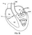
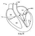
ここで図を参照すると、図1Aは、被検体の組織(106)の中へ固着された2つのアンカ(100)および(104)を示す。テザー(110)は、アンカ(100)に固定的に固着され、アンカ(104)のループ領域(114)を通される。図1Bに示されるように、テザー(110)が矢印(A1)の方向に引張られると、アンカ(100)と(104)とが近づけられ、アンカ(100)と(104)との間の組織の長さが短縮されるように締め上げ効果が生じる。このように、組織(106)は、アンカ(100)と(104)との間で圧縮される。2つのアンカが図1Aおよび1Bに示されているが、場合によっては、複数のアンカが使用されてもよい。テザー(110)が所望の量だけ引張られた後に、テザー(110)は、引張力を維持するようにロックされてもよく、場合によっては、テザー(110)の余分な部分が切断され、除去されてもよい。 Referring now to the figures, FIG. 1A shows two anchors (100) and (104) anchored into a subject's tissue (106). The tether (110) is fixedly secured to the anchor (100) and passed through the loop region (114) of the anchor (104). As shown in FIG. 1B, when the tether (110) is pulled in the direction of the arrow (A1), the anchors (100) and (104) are brought closer together, and the tissue between the anchors (100) and (104). The tightening effect is produced so that the length of the is shortened. In this way, tissue (106) is compressed between anchors (100) and (104). Although two anchors are shown in FIGS. 1A and 1B, in some cases, multiple anchors may be used. After the tether (110) is pulled by the desired amount, the tether (110) may be locked to maintain the tensile force, and in some cases, an excess portion of the tether (110) is cut and removed. May be.
上記の過程は、多種多様な組織において使用されてもよい。例えば、いくつかの変化例では、テザーによって相互に接続されるアンカが、僧帽弁輪の領域中の組織の中へ配備されてもよい。次いで、テザーは、(例えば、僧帽弁逆流を低減するために)僧帽弁輪を再構築する締め上げ効果を提供することに役立つように、引張られてもよい。その後、テザーは、締め上げ効果を維持するように適所にロックされてもよい。次いで、余分なテザー材料が切断され、除去されてもよい。僧帽弁修復は、例えば、それらの全体で参照することにより以前に組み込まれた、米国特許出願公開第2006/0190030A1号、第2006/0122633A1号、および第2008/0172035A1号、ならびに、その全体で参照することにより本明細書に組み込まれる、米国特許出願公開第2008/0177380A1号で説明されている。ある変化例では、上記の過程は、弁機能障害を体験している心臓を修復するために使用される、心室リモデリング手技等の心臓再形成手技で使用されてもよい。心臓再形成手技を含む、心臓修復手技は、例えば、その全体で参照することにより本明細書に組み込まれる、米国特許出願公開第2009/0234318A1号で説明されている。 The above process may be used in a wide variety of tissues. For example, in some variations, anchors interconnected by a tether may be deployed into tissue in the region of the mitral annulus. The tether may then be pulled to help provide a tightening effect that reconstructs the mitral annulus (eg, to reduce mitral regurgitation). Thereafter, the tether may be locked in place to maintain the tightening effect. The excess tether material may then be cut and removed. Mitral valve repair is described, for example, in US Patent Application Publication Nos. 2006 / 0193030A1, 2006 / 0122633A1, and 2008 / 0172035A1, previously incorporated by reference in their entirety, and in their entirety. It is described in US Patent Application Publication No. 2008/0177380 A1, which is incorporated herein by reference. In one variation, the above process may be used in a cardiac remodeling procedure, such as a ventricular remodeling procedure, used to repair a heart experiencing valve dysfunction. Cardiac repair procedures, including cardiac remodeling procedures, are described in, for example, US Patent Application Publication No. 2009 / 0234318A1, which is incorporated herein by reference in its entirety.
上記で論議されるように、本明細書で説明されるデバイスおよび方法は、適宜に、体内のいくつかの異なる部位のうちのいずれかで、および/またはいくつかの異なる種類の手技のうちのいずれかを支援するために、使用されてもよい。一実施例として、本明細書で説明されるデバイスおよび方法は、NOTES手技で使用されてもよい。別の実施例では、本明細書で説明されるデバイスおよび方法は、僧帽弁修復を伴うもの以外の心臓手技で使用されてもよい。例えば、それらは、大動脈弁または三尖弁を修復するため、または人工心臓弁を固定するために使用されてもよく、あるいは、それらは心臓ポートで使用されてもよい。別の実施例として、デバイスおよび方法は、1つ以上のテザーが弁形成リングを補強するために使用される、手技で採用されてもよい。加えて、本明細書で説明されるデバイスおよび方法は、例えば、種々の切開手術手技で使用されてもよい。 As discussed above, the devices and methods described herein may be used at any of several different locations within the body and / or of several different types of procedures, as appropriate. It may be used to assist either. As one example, the devices and methods described herein may be used in a NOTES procedure. In another example, the devices and methods described herein may be used in cardiac procedures other than those involving mitral valve repair. For example, they may be used to repair an aortic or tricuspid valve, or to fix a prosthetic heart valve, or they may be used at a heart port. As another example, the device and method may be employed in procedures where one or more tethers are used to reinforce the annuloplasty ring. In addition, the devices and methods described herein may be used in various open surgical procedures, for example.
ここで説明される方法およびデバイスとともに使用するためのアンカは、任意の好適なアンカであってもよい。アンカは、任意の好適な材料でできていてもよく、任意の好適なサイズであってもよく、および任意の好適な形状であってもよい。アンカは、1つの材料または2つ以上の材料でできていてもよい。アンカの材料の実施例は、ニッケル・チタン合金およびバネステンレス鋼等の超弾性または形状記憶材料を含む。アンカの形状の実施例は、Tタグ、リベット、ステープル、フック(例えば、C字形または半円形フック、他の形状の曲線フック、直線フック、有刺フック)、複数のループ状アンカ、クリップ、および同等物を含む。アンカは、自己拡張し、組織の中へ自己固定するように構成されてもよいが、そのような様式で構成される必要はない。同じ形状の複数のアンカが使用されてもよく、または異なる形状を有する複数のアンカが使用されてもよい。同様に、同じサイズの複数のアンカが使用されてもよく、または異なるサイズを有する複数のアンカが使用されてもよい。好適なアンカの例示的実施例は、例えば、その全てが、それらの全体で参照することにより本明細書に組み込まれる、米国特許出願公開第2005/0273138A1号、同第2008/0058868A1号、同第2008/0045982A1号、同第2008/0045983A1号、同第2008/0051810A1号、および同第2008/0051832A1号、で説明されている。また、アンカが説明されているが、任意の他の種類の好適な締結具またはインプラント(例えば、リード線、電極等)が、ここで説明されるデバイスおよび/または方法のうちの1つ以上とともに使用されてもよい。加えて、本明細書で説明されるデバイスおよび方法を採用するいくつかの手技は、いずれのアンカまたは他の種類の締結具も伴わなくてもよい。一実施例として、ここで説明されるデバイスおよび方法のある変化例は、組織を通して縫われたテザーをロックおよび/または切断するために使用されてもよい。 The anchor for use with the methods and devices described herein may be any suitable anchor. The anchor may be made of any suitable material, may be of any suitable size, and may be of any suitable shape. The anchor may be made of one material or more than one material. Examples of anchor materials include superelastic or shape memory materials such as nickel-titanium alloys and spring stainless steel. Examples of anchor shapes include T-tags, rivets, staples, hooks (eg, C-shaped or semi-circular hooks, other shaped curved hooks, straight hooks, barbed hooks), multiple looped anchors, clips, and Including equivalents. The anchor may be configured to self-expand and self-secure into the tissue, but need not be configured in such a manner. Multiple anchors of the same shape may be used, or multiple anchors having different shapes may be used. Similarly, multiple anchors of the same size may be used, or multiple anchors having different sizes may be used. Illustrative examples of suitable anchors include, for example, U.S. Patent Application Publication Nos. 2005 / 0273138A1, 2008 / 0058868A1, all of which are incorporated herein by reference in their entirety. 2008 / 0045982A1, 2008 / 0045983A1, 2008 / 0051810A1, and 2008 / 0051832A1. Also, although anchors are described, any other type of suitable fastener or implant (eg, lead, electrode, etc.) may be used with one or more of the devices and / or methods described herein. May be used. In addition, some procedures employing the devices and methods described herein may not involve any anchors or other types of fasteners. As one example, certain variations of the devices and methods described herein may be used to lock and / or cut a tether sewn through tissue.
テザーは、材料の1つの長い断片または2つ以上の断片であってもよく、縫合糸、縫合糸状材料、DACRON(登録商標)ポリエステル細片、または同等物等の、任意の好適な材料を含んでもよい。いくつかの変化例では、テザーは、モノフィラメントまたはマルチフィラメント織物用繊維糸または繊維の形態であってもよい。テザーはまた、種々の編組織物構成を有してもよい。1本のテザーを使用する、組織引き締めまたは圧縮手技が説明されているが、組織を修正するための他の手技は、2本、3本、4本、5本、または10本のテザー等の複数のテザーの使用を伴ってもよい。複数のテザーが使用されるとき、テザーのうちの少なくともいくつかは、異なるアンカと関連付けられ(例えば、固定的に取り付けられ)てもよく、および/またはテザーのうちの少なくともいくつかは、同じアンカと関連付けられ(例えば、固定的に取り付けられ)てもよい。本明細書で説明されるデバイスおよび方法は、単一テザー手技に、または複数テザー手技に適用されてもよい。一実施例として、ロックおよび/または切断デバイスが、同時に、または異なるときに、2つ以上のテザーを引張る、ロックする、および/または切断するために使用されてもよい。 The tether may be one long piece or two or more pieces of material, including any suitable material, such as sutures, suture-like materials, DACRON® polyester strips, or the like. But you can. In some variations, the tether may be in the form of a monofilament or multifilament textile fiber yarn or fiber. The tether may also have various knitted fabric configurations. While a tissue tightening or compression procedure using one tether has been described, other procedures for modifying the tissue include two, three, four, five, or ten tethers, etc. It may involve the use of multiple tethers. When multiple tethers are used, at least some of the tethers may be associated with different anchors (eg, fixedly attached) and / or at least some of the tethers may be the same anchor (Eg, fixedly attached). The devices and methods described herein may be applied to a single tether procedure or to a multiple tether procedure. As one example, a locking and / or cutting device may be used to pull, lock, and / or cut two or more tethers simultaneously or at different times.
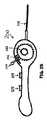
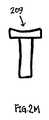
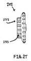
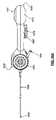
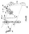
場合によっては、テザーは、手で引張られてもよい。代替として、または加えて、1つ以上の引張デバイスが、テザーを引張るために使用されてもよい。例えば、図2A−2Zは、テザー引張デバイス(200)およびその構成要素の変化例を示す。図2A−2Cに示されるように、テザー引張デバイス(200)は、その遠位部分にロック要素(212)を有する細長い部材(206)に連結されるハンドル部分(201)を備える。ロック要素(212)は、細長い部材(206)の遠位部分に位置し、ロック要素は、代替として、または加えて、細長い部材の他の部分に位置してもよい。細長い部材(206)は、例えば、カテーテルの形態であってもよい。ハンドル部分(201)は、筐体(203)と、筐体(203)に連結される回転可能な引張部材(205)と、筐体(203)の中の二重切り込み開口(246)から突出する解放レバー(204)とを備える。具体的に図2Cを参照すると、回転可能な引張部材(205)は、引張車輪(202)と、ネジ(214)によって連結されるボビン(216)とを備える。回転可能な引張部材(205)は、さらに圧縮バネ(218)と、歯車(220)(図2D−2G)とを備える。ハンドル部分(201)はまた、小穴ボタン摺動部(207)と、大穴ボタン摺動部(209)とを備える。ボタン摺動部は、以下でさらに詳細に説明されるように、細長い部材(206)の遠位部分のロック要素を作動させ、解放するように構成される。 In some cases, the tether may be pulled by hand. Alternatively or additionally, one or more tensioning devices may be used to tension the tether. For example, FIGS. 2A-2Z show variations of the tether tensioning device (200) and its components. As shown in FIGS. 2A-2C, the tether tensioning device (200) includes a handle portion (201) coupled to an elongate member (206) having a locking element (212) at its distal portion. The locking element (212) may be located at the distal portion of the elongated member (206), and the locking element may alternatively or additionally be located at other portions of the elongated member. The elongate member (206) may be, for example, in the form of a catheter. The handle portion (201) protrudes from a housing (203), a rotatable tension member (205) coupled to the housing (203), and a double cut opening (246) in the housing (203). Release lever (204). Referring specifically to FIG. 2C, the rotatable tensioning member (205) comprises a tensioning wheel (202) and a bobbin (216) connected by a screw (214). The rotatable tension member (205) further comprises a compression spring (218) and a gear (220) (FIGS. 2D-2G). The handle portion (201) also includes a small hole button sliding portion (207) and a large hole button sliding portion (209). The button slide is configured to actuate and release a locking element at the distal portion of the elongate member (206), as described in more detail below.
ボタン摺動部(207)および(209)の運動は、その内側に摺動部が摺動可能に配置されるスロットの中に嵌合するように構成される可撤性保持器によって制約されてもよい。例えば、図2Aは、適所にあるときに小穴ボタン摺動部(207)による運動を制限または防止する第1の保持器(208)と、適所にあるときに大穴ボタン摺動部(209)による運動を制限または防止する第2の保持器(210)とを示す。(図2Bは、第1および第2の保持器(208)および(210)が除去されたときのハンドル部分(201)を示す。適所にあるときに、保持器(208)および(210)は、その上でボタン摺動部(207)および(209)が摺動する進路を物理的に妨害する。具体的な構成を有する保持器が示されているが、ボタン摺動部(または任意の他の適切なアクチュエータ)を一時的に妨害または制約することに好適な任意の構成を有する保持器が使用されてもよいことを理解されたい。 The movement of the button slides (207) and (209) is constrained by a removable retainer configured to fit within a slot in which the slide is slidably disposed. Also good. For example, FIG. 2A shows a first retainer (208) that limits or prevents movement by the small hole button slide (207) when in place and a large hole button slide (209) when in place. Figure 2 shows a second retainer (210) that limits or prevents movement. (FIG. 2B shows the handle portion (201) when the first and second retainers (208) and (210) are removed. When in place, the retainers (208) and (210) , On which the sliding path of the button sliding parts (207) and (209) is physically obstructed, a retainer having a specific configuration is shown, but the button sliding part (or any It should be understood that a retainer having any configuration suitable for temporarily obstructing or constraining other suitable actuators) may be used.
図2Dは、テザー引張デバイス(200)の分解図を示す。そこで示されるように、解放レバー(204)は、回転可能な引張部材(205)の歯車(220)の個々の歯と係合することができる段部分(217)を備える。そこでも示されるように、細長い部材(206)の近位部分が、筐体(203)内に配置される。細長い部材(206)は、外側部材(290)と、外側部材の管腔内に少なくとも部分的に配置される内側部材(211)とを備える。外側部材(290)は、大穴ボタン摺動部(209)の中の開口(222)を通過し、内側部材(211)は、小穴ボタン摺動部(207)の中の開口(224)を通過する。示されるように、開口(222)の直径は、開口(224)の直径よりも大きくてもよい。また、外側部材(290)が開口(224)を通過できないように、外側部材(290)の直径は、開口(224)の直径よりも大きくてもよい。 FIG. 2D shows an exploded view of the tether tensioning device (200). As shown there, the release lever (204) comprises a stepped portion (217) that can engage individual teeth of the gear (220) of the rotatable tensioning member (205). As also shown, the proximal portion of the elongate member (206) is disposed within the housing (203). The elongate member (206) comprises an outer member (290) and an inner member (211) disposed at least partially within the lumen of the outer member. The outer member (290) passes through the opening (222) in the large hole button sliding portion (209), and the inner member (211) passes through the opening (224) in the small hole button sliding portion (207). To do. As shown, the diameter of the opening (222) may be larger than the diameter of the opening (224). Also, the diameter of the outer member (290) may be larger than the diameter of the opening (224) so that the outer member (290) cannot pass through the opening (224).
テザー引張デバイス(200)は、テザーを引張る、および/またはロックするために使用されてもよい。いくつかの変化例では、テザー引張方法は、図2Cに示されるように、テザーを回転可能な引張部材(205)に連結するステップと、所望の量だけテザー(213)を引張るために回転可能な引張部材を回転させるステップとを含む。より具体的には、テザー(213)は、ボビン(216)の中の切り込み(215)の中へテザーを通し、次いで、ボビンの周囲にテザーを巻装することによって、ボビン(216)に固定されてもよい。引張車輪(202)およびボビン(216)は、一致して回転するように連結される。したがって、テザー(213)は、1つの方向に引張車輪(202)を回転させることによって引張られてもよく、テザー(213)の引張力のいくらかまたは全ては、反対方向に引張車輪(202)を回転させることによって解放されてもよい。テザー(213)は、連続および/または離散増分で引張られてもよい。ある変化例では、テザーに印加された引張力の量が測定されてもよい。一実施例として、トルクゲージが引張車輪(202)に設置されてもよく、テザー引張力は、ボビン(216)の中心から切り込み(215)までの半径方向距離に基づいて測定されてもよい。 The tether tensioning device (200) may be used to tension and / or lock the tether. In some variations, the tether tensioning method can be coupled to connect the tether to the rotatable tensioning member (205) and rotatable to pull the tether (213) by the desired amount, as shown in FIG. 2C. Rotating the tension member. More specifically, the tether (213) is secured to the bobbin (216) by passing the tether through a notch (215) in the bobbin (216) and then winding the tether around the bobbin. May be. The tensioning wheel (202) and the bobbin (216) are connected to rotate in unison. Thus, the tether (213) may be pulled by rotating the tensioning wheel (202) in one direction, and some or all of the tensile force of the tether (213) causes the tensioning wheel (202) to move in the opposite direction. It may be released by rotating. The tether (213) may be pulled in continuous and / or discrete increments. In some variations, the amount of tensile force applied to the tether may be measured. As one example, a torque gauge may be installed on the tensioning wheel (202) and the tether tension may be measured based on the radial distance from the center of the bobbin (216) to the notch (215).
回転可能な引張部材(205)は、図2E−2Qでさらに詳細に図示されている。そこで示されるように、引張車輪(202)は、ネジ(214)を介してボビン(216)および歯車(220)に連結される。ボビン(216)と歯車(220)との間に配置される圧縮バネ(218)は、引張車輪(202)が回転させられると、回転可能な引張部材全体が回転することを可能にする。いくつかの変化例では、圧縮バネ(218)は、約10lb/インチから約30lb/インチのバネ定数を有してもよい。圧縮バネ(218)は、鋼鉄、アルミニウム、および/またはELGILOY(登録商標)合金等であるが、それらに限定されない1つまたは複数の任意の好適な材料でできていてもよい。引張車輪(202)、ボビン(216)、および/または歯車(220)に対する好適な材料の実施例は、ポリカーボネートおよびアクリロニトリルブタジエンスチレン(ABS)等のポリマーを含む。代替として、または加えて、他の好適な材料が使用されてもよい。引張車輪、ボビン、および歯車は、同じ材料または異なる材料でできていてもよい。ネジ(214)は、例えば、1つ以上の金属合金(例えば、ステンレス鋼)、および/またはポリカーボネートおよびアクリロニトリルブタジエンスチレン(ABS)等のポリマーでできていてもよい。 The rotatable tension member (205) is illustrated in more detail in FIGS. 2E-2Q. As shown there, the tensioning wheel (202) is connected to the bobbin (216) and the gear (220) via a screw (214). A compression spring (218) disposed between the bobbin (216) and the gear (220) allows the entire rotatable tensioning member to rotate when the tensioning wheel (202) is rotated. In some variations, the compression spring (218) may have a spring constant of about 10 lb / inch to about 30 lb / inch. The compression spring (218) may be made of one or more any suitable material such as, but not limited to, steel, aluminum, and / or ELGILOY® alloy. Examples of suitable materials for the tensioning wheel (202), bobbin (216), and / or gear (220) include polymers such as polycarbonate and acrylonitrile butadiene styrene (ABS). Alternatively or in addition, other suitable materials may be used. The tensioning wheel, bobbin, and gear may be made of the same material or different materials. The screw (214) may be made of, for example, one or more metal alloys (eg, stainless steel) and / or polymers such as polycarbonate and acrylonitrile butadiene styrene (ABS).
引張車輪(202)は、ボビン(216)上の軸受(228)に対応する戻り止め(226)を備える。使用時に、圧縮バネ(218)は、歯車(220)、ボビン(216)、および引張車輪(202)を一緒に押す。これらの構成要素がともに圧縮されると、軸受(228)が戻り止め(226)に係合し、それは、引張車輪(202)およびボビン(216)が一致して回転することを可能にする。戻り止めおよび軸受は、相互に係合することができるように、任意のサイズまたは形状であってもよい。また、任意の他の好適な数の戻り止めおよび軸受が使用されてもよい。 The tensioning wheel (202) includes a detent (226) corresponding to a bearing (228) on the bobbin (216). In use, compression spring (218) pushes gear (220), bobbin (216), and tensioning wheel (202) together. When these components are compressed together, the bearing (228) engages the detent (226), which allows the tensioning wheel (202) and bobbin (216) to rotate in unison. The detents and bearings may be of any size or shape so that they can engage each other. Any other suitable number of detents and bearings may also be used.
一旦テザーがボビン(216)に連結されると、引張車輪を旋回することによりボビンも旋回させ、それにより、テザーを引張る。加えて、圧縮バネ(218)のバネ力に対抗するトルクが生成される。トルク力がバネ力を超える場合には、軸受(228)が戻り止め(226)から外へ押し進められ、ボビン(216)が滑動して引張車輪(202)から係脱される。結果として、引張車輪の回転は、もはやボビンの回転をもたらさなくなる。したがって、回転可能な引張部材(205)の構成が、テザーに印加することができる最大引張力を設定し、その時点の後に、ボビンが引張車輪から係脱され、デバイスは、テザーの引張力をさらに増加させるために使用され得ない。 Once the tether is connected to the bobbin (216), the bobbin is also turned by turning the tensioning wheel, thereby pulling the tether. In addition, a torque is generated that opposes the spring force of the compression spring (218). If the torque force exceeds the spring force, the bearing (228) is pushed out of the detent (226) and the bobbin (216) slides and disengages from the tension wheel (202). As a result, rotation of the tensioning wheel no longer results in rotation of the bobbin. Thus, the configuration of the rotatable tension member (205) sets the maximum tension force that can be applied to the tether, after which time the bobbin is disengaged from the tension wheel and the device reduces the tether tension force. It cannot be used to increase further.
圧縮バネ(218)のバネ力は、圧縮バネの剛性に依存する。したがって、圧縮バネの剛性は、テザーに印加される所望の最大引張力に基づいて選択されてもよい。高い圧縮バネ剛性を有する回転可能な引張部材は、概して、低い圧縮バネ剛性を有する回転可能な引張部材よりも高い最大テザー引張力を可能にし得る。圧縮バネの剛性は、圧縮バネのバネ定数に関係している。バネ定数が増加するにつれて、剛性も増加する。 The spring force of the compression spring (218) depends on the rigidity of the compression spring. Accordingly, the stiffness of the compression spring may be selected based on the desired maximum tensile force applied to the tether. A rotatable tension member having a high compression spring stiffness may generally allow a higher maximum tether tensile force than a rotatable tension member having a low compression spring stiffness. The rigidity of the compression spring is related to the spring constant of the compression spring. As the spring constant increases, the stiffness also increases.
圧縮バネの使用は、デバイスが、テザーに印加される引張力のレベルを制約し、それにより、テザーの意図しない過度の引張を防止する機構の一変化例にすぎない。同じ機能を果たす、他の機構も使用されてもよい。例えば、ある変化例では、圧縮バネの代わりに、引張車輪をボビンに係合させるために、ゴム座金等の高牽引力要素が使用されてもよい。一旦テザーにかかる引張力が高牽引力要素によって生成される反対摩擦力を超えると、ボビンは、もはや引張車輪とともに回転可能ではなくなり、引張デバイスは、テザーにかかる引張力をさらに増加させることができない。これらは、引張デバイスとともに適用することができる、最大引張力閾値を設定する機構のいくつかの実施例にすぎず、代替として、または加えて、他の方向および構成が使用されてもよいことを理解されたい。 The use of a compression spring is only one variation of the mechanism by which the device limits the level of tensile force applied to the tether, thereby preventing unintentional excessive tensioning of the tether. Other mechanisms that perform the same function may also be used. For example, in one variation, instead of a compression spring, a high traction element such as a rubber washer may be used to engage the tensioning wheel with the bobbin. Once the tensile force on the tether exceeds the counter friction force generated by the high traction element, the bobbin is no longer rotatable with the tensioning wheel and the tensioning device cannot further increase the tensile force on the tether. These are only some examples of mechanisms for setting a maximum tensile force threshold that can be applied with a tensioning device, and that other orientations and configurations may alternatively or additionally be used. I want you to understand.
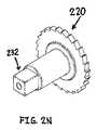
図2N−2Uは、回転可能な引張部材(205)の種々の構成要素をさらに詳細に示す。最初に図2Nおよび2Oを参照すると、歯車(220)は、その歯のそれぞれの間の歯間距離(230)を有する。この歯間距離は、テザーが引張られているときに引張力を増加させることができる、離散間隔を確立する。歯車(220)の各歯の間の歯間距離は、均一として示されているが、いくつかの変化例では、歯車は、異なる距離で相互から分離している歯を備えてもよい(すなわち、距離のうちの少なくとも2つが、相互とは異なってもよく、例えば、距離は、歯車の円周全体に沿って変化してもよい)。ある変化例では、歯間距離(230)は、例えば、約0.1インチから約0.3インチであってもよい。歯間距離(230)は、例えば、所望のレベルのテザー引張の精度に基づいて選択されてもよい。歯間距離が小さいほど、(すなわち、テザー引張力がより小さい増分で調整されるため)テザーにかかる引張力がより正確に調整されてもよいことを理解されたい。具体的には、ここで図2Nを参照すると、歯車(220)の中心軸上の長方形の要素(232)が、歯車(220)を引張車輪(202)に連結する。しかしながら、歯車を引張車輪に連結するために、他の形状および/または取付方法が使用されてもよい。例えば、歯車は、永久接着剤、溶接、および/またはネジを使用して、引張車輪に連結されてもよい。 2N-2U show in more detail the various components of the rotatable tensioning member (205). Referring initially to FIGS. 2N and 2O, the gear (220) has an inter-tooth distance (230) between each of its teeth. This interdental distance establishes a discrete spacing that can increase the pulling force when the tether is being pulled. The inter-tooth distance between each tooth of the gear (220) is shown as uniform, but in some variations, the gear may comprise teeth that are separated from each other at different distances (ie, , At least two of the distances may be different from each other, for example, the distance may vary along the entire circumference of the gear). In some variations, the interdental distance (230) may be, for example, from about 0.1 inch to about 0.3 inch. The interdental distance (230) may be selected based on, for example, a desired level of tether tension accuracy. It should be understood that the smaller the interdental distance, the more accurately the tensile force applied to the tether may be adjusted (ie, because the tether tensile force is adjusted in smaller increments). Specifically, referring now to FIG. 2N, a rectangular element (232) on the central axis of the gear (220) connects the gear (220) to the tensioning wheel (202). However, other shapes and / or attachment methods may be used to connect the gear to the tensioning wheel. For example, the gear may be coupled to the tensioning wheel using permanent adhesive, welding, and / or screws.
図2Pおよび2Qは、ボビン(216)をさらに詳細に示す。そこで示されるように、ボビン(216)は、突出軸受(228)を含む第1の表面(234)と、切り込み(215)を含む第2の表面(236)と、2つの表面を接続する軸要素(235)とを備える。表面は、任意の好適な形状(例えば、円形、長方形等)であってもよい。第1の表面(234)は、第1の表面(234)上に放射状に配設される、36個の半球軸受(228)を含む。しかしながら、引張車輪(202)の中の戻り止め(226)と係合することが可能である限り、任意の適切な数の任意の形状の軸受が使用されてもよい。第1の表面、第2の表面、軸要素、および軸受(228)は、1つ以上のポリマー(例えば、ポリカーボネートおよびアクリロニトリルブタジエンスチレン(ABS))、および金属合金(例えば、ステンレス鋼)等の、任意の材料または材料の組み合わせでできていてもよい。ボビン(216)の異なる構成要素は、1つまたは複数の同じ材料でできていてもよく、または異なる材料でできていてもよい。例えば、いくつかの変化例では、第1の表面、第2の表面、および軸は、ポリカーボネートでできていてもよく、軸受は、ステンレス鋼でできていてもよい。 2P and 2Q show the bobbin (216) in more detail. As shown there, the bobbin (216) has a first surface (234) that includes a protruding bearing (228), a second surface (236) that includes a notch (215), and an axis connecting the two surfaces. Element (235). The surface may be any suitable shape (eg, circular, rectangular, etc.). The first surface (234) includes 36 hemispherical bearings (228) disposed radially on the first surface (234). However, any suitable number of arbitrarily shaped bearings may be used as long as it is possible to engage the detent (226) in the tensioning wheel (202). The first surface, the second surface, the shaft element, and the bearing (228) include one or more polymers (eg, polycarbonate and acrylonitrile butadiene styrene (ABS)), and metal alloys (eg, stainless steel), It may be made of any material or combination of materials. Different components of the bobbin (216) may be made of one or more of the same materials, or may be made of different materials. For example, in some variations, the first surface, the second surface, and the shaft may be made of polycarbonate and the bearing may be made of stainless steel.
上記で説明されるように、ボビン(216)は、軸要素(235)の周囲に巻装されたテザーの固定に役立つ、第2の表面(236)上の切り込み(215)を含む。ある変化例では、テザーは、1つ以上の一時的接着剤を使用して、さらに固定されてもよい。ボビン(216)は、1つだけの切り込み(215)を含むが、ボビンのいくつかの変化例は、2つ、3つ、4つ、または5つの切り込み等の複数の切り込みを含んでもよい。加えて、ある変化例では、軸要素(235)は、摩擦増進特徴を備えてもよい。例えば、図2Qに示されるように、軸要素(235)は、隆起(237)を備えてもよい。代替として、または加えて、軸要素は、その表面上に1つ以上の粘着性または接着性被覆を備えてもよい(例えば、KRATONTMポリマー等の1つ以上の軟質エラストマー材料で形成される)。ボビンの軸要素、ならびにボビンによって引張られているテザーは、軸要素とテザーとの間の係合を増進する、任意の数の特徴、被覆、またはそれらの組み合わせを備えてもよい。As described above, the bobbin (216) includes a notch (215) on the second surface (236) that helps secure the tether wrapped around the shaft element (235). In certain variations, the tether may be further secured using one or more temporary adhesives. Although the bobbin (216) includes only one cut (215), some variations of the bobbin may include multiple cuts, such as two, three, four, or five cuts. In addition, in certain variations, the shaft element (235) may include friction enhancing features. For example, as shown in FIG. 2Q, the shaft element (235) may comprise a ridge (237). Alternatively or additionally, the shaft element may be provided with one or more tacky or adhesive coatings on its surface (eg, formed of one or more soft elastomeric materials such as KRATON™ polymer). . The bobbin shaft element, as well as the tether being pulled by the bobbin, may comprise any number of features, coverings, or combinations thereof that enhance the engagement between the shaft element and the tether.
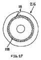
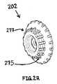
図2R−2Uは、引張車輪(202)をさらに詳細に示す。図2Rおよび2Tに示されるように、引張車輪(202)は、さらに大きい牽引力を提供するように、その外面(277)上に、隆起(275)および/またはグリップ等の突出特徴を備えてもよい。引張車輪(202)の内面(279)は、図2Sおよび2Uに示されるように、放射状に配設された戻り止め(226)を含有する。戻り止め(226)は、均等に離間した放射状配設にあるが、他の好適な配設が使用されてもよい。一実施例として、いくつかの変化例では、引張車輪は、相互から均一に離間していない、および/または放射状構成を形成しない、戻り止めを備えてもよい。戻り止め(226)は、ボビン(216)の中の軸受(228)と係合するように構成される。加えて、この変化例では、引張車輪(202)の中心軸は、歯車(220)の長方形の要素(232)(図2N)と係合する長方形の戻り止め(245)を備える。しかしながら、引張車輪および歯車の他の変化例は、1つ以上の戻り止めと、相互に係合するように構成される異なるサイズおよび/または形状の対応する要素とを備えてもよい。また、いくつかの変化例では、引張車輪は、(例えば、引張車輪とボビンとの間の牽引力を増進するように)その外面上の全体または一部分上に高摩擦材料を含んでもよい。引張車輪をボビンに係合するために、任意の好適な機構または材料が、引張車輪の表面(例えば、内面)上で使用されてもよいことを理解されたい。 2R-2U show the tensioning wheel (202) in more detail. As shown in FIGS. 2R and 2T, the tensioning wheel (202) may also include protruding features, such as ridges (275) and / or grips, on its outer surface (277) to provide greater traction. Good. The inner surface (279) of the tensioning wheel (202) contains detents (226) arranged radially as shown in FIGS. 2S and 2U. The detents (226) are in an evenly spaced radial arrangement, but other suitable arrangements may be used. As one example, in some variations, the tensioning wheels may include detents that are not uniformly spaced from each other and / or do not form a radial configuration. The detent (226) is configured to engage the bearing (228) in the bobbin (216). In addition, in this variation, the central axis of the tensioning wheel (202) includes a rectangular detent (245) that engages the rectangular element (232) (FIG. 2N) of the gear (220). However, other variations of tensioning wheels and gears may include one or more detents and corresponding elements of different sizes and / or shapes configured to engage one another. Also, in some variations, the tensioning wheel may include a high friction material on all or a portion of its outer surface (eg, to enhance traction between the tensioning wheel and the bobbin). It should be understood that any suitable mechanism or material may be used on the surface (eg, the inner surface) of the tensioning wheel to engage the tensioning wheel with the bobbin.
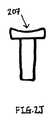
図2Xは、解放レバー(204)を拡大して詳細に示す。そこで示されるように、解放レバー(204)は、歯車(220)の歯と一時的に係合するように構成される段部分(217)を備える。解放レバー(204)は、引張デバイス(200)の頂面に形成される、二重切り込み開口(246)(図2Bおよび2Y)から延在する。解放レバー(204)が一方の切り込みの中に係合されると、離散間隔で、引張車輪(202)を一方向に回転させることができる。ある変化例では、この構成は、テザーの引張力が増分して増加させられることのみを可能にしてもよいが、他の変化例では、この構成は、引張力が増分して増加されるととともに減少させられることを可能にしてもよい。解放レバー(204)が他方の切り込みの中で係合されると、連続増分で、引張車輪(202)を双方向に回転させることができる。解放レバー(204)は、ポリマー(例えば、ポリカーボネートおよび/またはABS)等の1つまたは複数の任意の好適な材料でできていてもよい。また、解放レバーの他の変化例は、レバーが引張デバイスから延在することを要求しなくてもよいことも理解されたい。例えば、ある変化例では、解放レバーは、内部に実装され、摺動部またはボタンによって作動させられてもよい。いくつかの変化例では、解放レバーは、突起以外に、または突起に加えて、歯車の歯と連接することが可能である、1つ以上の特徴を備えてもよい。 FIG. 2X shows the release lever (204) in greater detail. As shown there, the release lever (204) comprises a stepped portion (217) configured to temporarily engage the teeth of the gear (220). The release lever (204) extends from a double cut opening (246) (FIGS. 2B and 2Y) formed in the top surface of the tensioning device (200). When the release lever (204) is engaged in one notch, the tensioning wheel (202) can be rotated in one direction at discrete intervals. In some variations, this configuration may only allow the tether tensile force to be incrementally increased, while in other variations, this configuration may be used when the tensile force is incrementally increased. It may be possible to be reduced with. When the release lever (204) is engaged in the other notch, the tensioning wheel (202) can be rotated bi-directionally in successive increments. Release lever (204) may be made of one or more of any suitable material, such as a polymer (eg, polycarbonate and / or ABS). It should also be appreciated that other variations of the release lever may not require the lever to extend from the tensioning device. For example, in one variation, the release lever may be mounted internally and actuated by a slide or button. In some variations, the release lever may include one or more features that may be coupled to the gear teeth in addition to or in addition to the protrusion.
上記で説明されるように、いくつかの変化例では、テザーは、同じデバイスによって引張られ、ロックされてもよい。ロックは、テザーの引張力を維持することに役立ってもよい(例えば、それにより、引張られたテザーによって生成される締め上げ効果を維持する)。例えば、テザー引張デバイス(200)は、細長い部材(206)の遠位部分にロック要素(212)を含む。したがって、テザーを引張るために使用されることに加えて、テザー引張デバイス(200)は、テザーをロックするためにも使用されてもよい。しかしながら、ある変化例では、テザーを引っ張り、ロックするために、2つの異なるデバイスが使用されてもよく、一方のデバイスはテザーを引張るために使用され、他方のデバイスはテザーをロックするために使用される。いくつかの変化例では、テザーを引っ張り、ロックし、切断するために、単一のデバイスが使用されてもよい。テザーリングは、以下でさらに詳細に説明される。また、ある変化例では、テザーを引張るように、およびテザーをロックおよび/切断するように構成されるデバイスは、テザーを引張るためだけ、またはテザーをロックおよび/切断するためだけに使用されてもよいことにも留意されたい。 As explained above, in some variations, the tether may be pulled and locked by the same device. The lock may help to maintain the tension of the tether (eg, thereby maintaining the tightening effect produced by the tensioned tether). For example, the tether tensioning device (200) includes a locking element (212) at the distal portion of the elongate member (206). Thus, in addition to being used to pull the tether, the tether pulling device (200) may also be used to lock the tether. However, in one variation, two different devices may be used to pull and lock the tether, one device used to pull the tether and the other device used to lock the tether. Is done. In some variations, a single device may be used to pull, lock, and cut the tether. Tethering is described in further detail below. Also, in certain variations, a device configured to pull the tether and lock and / or cut the tether may be used only to pull the tether or only to lock and / or cut the tether. Also note that it is good.
ここで、テザー引張デバイス(200)を使用してテザーをロックするために採用されてもよい機構および構成要素を説明する。図2Dを参照すると、ロック要素(212)のロック管にロック要素(212)のプラグを押し込むプッシュ部材として機能する、内側部材(211)を作動させるために、小穴ボタン摺動部(207)が使用されてもよい。内側部材(211)の作動の前に、テザーがロック管の中へ送られてもよい。したがって、内側部材(211)は、作動させられると、ロック管にプラグを押し込み、プラグとロック管との間でテザーを固定し、それにより、テザーをロックする。 The mechanisms and components that may be employed to lock the tether using the tether tensioning device (200) will now be described. Referring to FIG. 2D, a small hole button slide (207) is used to actuate the inner member (211), which acts as a push member that pushes the plug of the lock element (212) into the lock tube of the lock element (212). May be used. Prior to actuation of the inner member (211), a tether may be sent into the lock tube. Thus, when actuated, the inner member (211) pushes the plug into the lock tube and secures the tether between the plug and the lock tube, thereby locking the tether.
ある変化例では、テザーをロックするためにロック要素(212)が使用された後に、ロック要素は、テザー引張デバイス(200)の残りの部分から解放されてもよい。例えば、一旦テザーが引張られ、ロックされると、ロック要素は、体内にロック要素を残すようにデバイスから解放されてもよい。これは、次いで、体内にあるデバイスの任意の他の部分が身体から除去されることを可能にする。図2Dを再び参照すると、大穴ボタン摺動部(209)は、細長い部材(206)からロック要素(212)を分断し、それにより、テザー引張デバイス(200)の他の部分からロック要素を解放するように作動させられてもよい。 In one variation, after the locking element (212) is used to lock the tether, the locking element may be released from the rest of the tether tensioning device (200). For example, once the tether is pulled and locked, the locking element may be released from the device to leave the locking element in the body. This in turn allows any other part of the device in the body to be removed from the body. Referring again to FIG. 2D, the large hole button slide (209) decouples the locking element (212) from the elongated member (206), thereby releasing the locking element from the rest of the tether tensioning device (200). May be actuated to.
第1および第2の保持器(208)および(210)は、ロック要素(212)が適正に配備され、解放されることを確実にすることに役立つために使用されてもよい。言い換えれば、第1および第2の保持器は、ロック要素が解放される前に配備されること、およびロック要素が時期尚早に配備または解放されないことを確実にするために使用されてもよい。図2Y(解放レバー(204)がないハンドル部分(201)を図示する)を参照すると、小穴ボタン摺動部(207)は、ハンドル部分(201)の筐体(203)の中のスロット(238)内で摺動可能に配置される。スロット内で移動させられると、小穴ボタン摺動部(207)は、内側部材(211)を作動させ、内側部材が、ロック要素のロック管にロック要素(212)のプラグを押し込むことを可能にしてもよい。同様に、大穴ボタン摺動部(209)は、ハンドル部分(201)の筐体(203)の中のスロット(240)内で摺動可能に配置される。スロット(240)内で大穴ボタン摺動部(209)を移動させることにより、細長い部材(206)からのロック要素(212)の分断をもたらすことができる。第1および第2の保持器(208)および(210)は、間違ったときに(例えば、時期尚早に、または間違った順番で)ボタン摺動部(207)および(209)が作動させられることを防止するように、それぞれ、スロット(238)および(240)の中に一時的に配置されてもよい。両方の保持器が、同時に(例えば、配送中に)使用されてもよいが、いくつかの変化例では、1つだけの保持器が使用されてもよいことに留意されたい。 The first and second retainers (208) and (210) may be used to help ensure that the locking element (212) is properly deployed and released. In other words, the first and second retainers may be used to ensure that the locking element is deployed before it is released and that the locking element is not prematurely deployed or released. Referring to FIG. 2Y (illustrate the handle portion (201) without the release lever (204)), the small hole button slide (207) has a slot (238) in the housing (203) of the handle portion (201). ) In a slidable manner. When moved in the slot, the eyelet button slide (207) actuates the inner member (211), allowing the inner member to push the plug of the locking element (212) into the locking tube of the locking element. May be. Similarly, the large hole button sliding portion (209) is slidably disposed in the slot (240) in the housing (203) of the handle portion (201). Moving the large hole button slide (209) within the slot (240) can result in the breaking of the locking element (212) from the elongate member (206). The first and second cages (208) and (210) have their button slides (207) and (209) actuated in the wrong time (eg, prematurely or in the wrong order) May be temporarily placed in slots (238) and (240), respectively. It should be noted that both retainers may be used simultaneously (eg, during delivery), but in some variations, only one retainer may be used.
使用中に、両方の保持器(208)および(210)は、小穴ボタン摺動部(207)または大穴ボタン摺動部(209)の意図しない動作を防止するように、それぞれ、スロット(238)および(240)の中に最初に配置されてもよい。次いで、第1の保持器(208)が、小穴ボタン摺動部(207)の作動を可能にするようにスロット(238)から除去されてもよい一方で、大穴ボタン摺動部(209)の作動は、スロット(240)内の第2の保持器(210)の存在によって依然として禁止される。テザーをロックするように小穴ボタン摺動部が作動させられた後に、第2の保持器(210)は、スロット内での大穴ボタン摺動部(209)の移動を可能にするようにスロット(240)から除去されてもよく、それは、細長い部材(206)からのロック要素(212)の解放をもたらしてもよい。保持器(208)および(210)は、ハンドル部分(201)の筐体(203)の外部にあるものとして図示されているが、いくつかの変化例では、1つ以上の保持器が、ハンドル部分の筐体に対して内部に配置されてもよい。 During use, both retainers (208) and (210) are each slot (238) to prevent unintended movement of the small hole button slide (207) or large hole button slide (209), respectively. And (240) may be placed first. The first retainer (208) may then be removed from the slot (238) to allow actuation of the small hole button slide (207) while the large hole button slide (209) Operation is still prohibited by the presence of the second retainer (210) in the slot (240). After the small hole button slide is actuated to lock the tether, the second retainer (210) is slotted to allow movement of the large hole button slide (209) within the slot. 240), which may result in the release of the locking element (212) from the elongate member (206). Although the retainers (208) and (210) are illustrated as being external to the housing (203) of the handle portion (201), in some variations, one or more retainers may be You may arrange | position inside with respect to the housing | casing of a part.
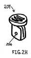
図2H−2Jは、小穴ボタン摺動部(207)を拡大して詳細に示す。小穴ボタン摺動部(207)は、例えば、ポリカーボネートおよび/またはABS等の1つ以上のポリマーでできていてもよい。小穴ボタン摺動部(207)の中の開口(224)の直径は、開口(224)が細長い部材(206)の内側部材(211)を受容することを可能にするように選択されてもよい。スロット(238)内の小穴ボタン摺動部(207)の移動が、内側部材(211)の対応する移動をもたらすように、内側部材は、開口との摩擦嵌合を形成してもよい。ある変化例では、内側部材は、(例えば、1つ以上の接着剤を使用して、および/または熱を印加して内側部材を小穴ボタン摺動部に融合することによって)小穴ボタン摺動部(207)にさらに連結されてもよい。 2H-2J show the details of the small hole button sliding portion (207) in an enlarged manner. The eyelet button slide (207) may be made of one or more polymers such as, for example, polycarbonate and / or ABS. The diameter of the opening (224) in the eyelet button slide (207) may be selected to allow the opening (224) to receive the inner member (211) of the elongate member (206). . The inner member may form a friction fit with the opening such that movement of the eyelet button slide (207) within the slot (238) results in corresponding movement of the inner member (211). In one variation, the inner member is a small hole button slide (eg, using one or more adhesives and / or by applying heat to fuse the inner member to the small button slide). (207) may be further connected.
図2K−2Mは、大穴ボタン摺動部(209)を拡大して詳細に示す。大穴ボタン摺動部(209)は、例えば、1つ以上のポリマー、例えば、ポリカーボネートおよび/またはABSでできていてもよい。大穴ボタン摺動部は、小穴ボタン摺動部と同じ材料のうちの1つ以上でできていてもよく、またはボタン摺動部は、異なる材料でできていてもよい。大穴ボタン摺動部(209)の中の開口(222)の直径は、開口(224)が細長い部材(206)の外側部材(290)を受容することを可能にするように選択されてもよい。スロット(240)内の大穴ボタン摺動部(209)の移動が、外側部材(290)の対応する移動をもたらすように、外側部材は、開口との摩擦嵌合を形成してもよい。いくつかの変化例では、外側部材(290)は、ロック要素(212)を一時的に保持するシースの形態であってもよい。大穴ボタン摺動部が作動させられると、外側部材(290)の近位引出をもたらしてもよく、それは順に、細長い部材(206)からのロック要素(212)の解放をもたらしてもよい。 FIGS. 2K-2M show the enlarged large hole button sliding part (209) in detail. The large hole button slide (209) may be made of, for example, one or more polymers, such as polycarbonate and / or ABS. The large hole button sliding part may be made of one or more of the same materials as the small hole button sliding part, or the button sliding part may be made of a different material. The diameter of the opening (222) in the large hole button slide (209) may be selected to allow the opening (224) to receive the outer member (290) of the elongate member (206). . The outer member may form a friction fit with the opening such that movement of the large hole button slide (209) within the slot (240) results in a corresponding movement of the outer member (290). In some variations, the outer member (290) may be in the form of a sheath that temporarily holds the locking element (212). When the large hole button slide is actuated, it may result in proximal withdrawal of the outer member (290), which in turn may result in release of the locking element (212) from the elongate member (206).
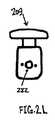
図2Vは、第1の保持器(208)を拡大して詳細に示す。第1の保持器(208)は、例えば、ポリカーボネートおよび/またはABS等の1つ以上のポリマーでできていてもよい。上記で説明されるように、第1の保持器(208)は、スロット(238)内で嵌合するようにサイズ決定および成形され、それにより、小穴ボタン摺動部(207)を不動にする(例えば、ロック要素(212)の意図しない作動を防止する)。第1の保持器(208)のサイズおよび形状は、また両方の保持器がハンドル部分(201)の筐体(203)の中のそれぞれのスロットの中に配置されると、第1の保持器が第2の保持器と十分に嵌合するように選択されてもよい。 FIG. 2V shows the first retainer (208) in greater detail. The first retainer (208) may be made of one or more polymers such as, for example, polycarbonate and / or ABS. As explained above, the first retainer (208) is sized and shaped to fit within the slot (238), thereby immobilizing the eyelet button slide (207). (For example, preventing unintentional actuation of the locking element (212)). The size and shape of the first retainer (208) is also determined when both retainers are placed in respective slots in the housing (203) of the handle portion (201). May be selected to fit well with the second retainer.
図2Wは、第2の保持器(210)を拡大して詳細に示す。第2の保持器(210)は、例えば、ポリカーボネートおよび/またはABS等の1つ以上のポリマーでできていてもよい。上記で説明されるように、第2の保持器(210)は、スロット(240)内で嵌合するようにサイズ決定および成形され、それにより、大穴ボタン摺動部(209)を不動にする(例えば、細長い部材(206)からのロック要素(212)の意図しない解放を防止する)。 FIG. 2W shows the second retainer (210) in greater detail. The second retainer (210) may be made of one or more polymers such as, for example, polycarbonate and / or ABS. As described above, the second retainer (210) is sized and shaped to fit within the slot (240), thereby immobilizing the large hole button slide (209). (For example, preventing unintentional release of the locking element (212) from the elongated member (206)).
第1および第2の保持器(208)および(210)は、第1の保持器(208)がスロット(238)から除去されるまで、第2の保持器(210)をスロット(240)から容易に除去することができないように構成されてもよい。この構成は、小穴ボタン摺動部(207)の作動の前に大穴ボタン摺動部(209)が作動させられないことを確実にしてもよい。結果として、ロック要素(212)は、テザーをロックするように作動させられる前に、細長い部材(206)から不注意に解放され得ない。例えば、具体的には図2Zを参照すると、第1の保持器(208)の高さ(242)は、第2の保持器(210)の高さ(244)よりも大きくてもよい。第1および第2の保持器が両方とも、ハンドル部分(201)の筐体(203)の中のそれぞれのスロットの中に配置されると、図2Zに示されるように、この高さの差が、第1の保持器(208)の上縁(285)を、第2の保持器(210)の上縁(287)を覆って延在させる。これは、1つの保持器構成にすぎず、ボタン摺動部(207)および/または(209)の意図しない作動を防止するために、および/または小穴ボタン摺動部(207)が大穴ボタン摺動部(209)の前に作動させられることを確実にするために、保持器構成の他の変化例が使用されてもよいことを理解されたい。 The first and second cages (208) and (210) remove the second cage (210) from the slot (240) until the first cage (208) is removed from the slot (238). You may comprise so that it cannot remove easily. This configuration may ensure that the large hole button slide (209) is not actuated before the small hole button slide (207) is actuated. As a result, the locking element (212) cannot be inadvertently released from the elongate member (206) before being actuated to lock the tether. For example, referring specifically to FIG. 2Z, the height (242) of the first cage (208) may be greater than the height (244) of the second cage (210). When both the first and second retainers are placed in their respective slots in the housing (203) of the handle portion (201), this height difference is shown in FIG. 2Z. Causes the upper edge (285) of the first retainer (208) to extend over the upper edge (287) of the second retainer (210). This is only one cage configuration to prevent unintentional operation of the button slides (207) and / or (209) and / or the small hole button slide (207) is a large hole button slide. It should be understood that other variations of the retainer configuration may be used to ensure that it is actuated before the moving part (209).
いくつかの変化例では、テザー引張デバイスは、デバイスの筐体内に配置される1つ以上の保持器を備えてもよい。代替として、または加えて、テザー引張デバイスは、デバイスの筐体の中または外へ突出しない1つ以上の保持器を備えてもよい。例えば、保持器は、スロットを一時的に覆って、スロット内のボタン摺動部の移動を制限する接着細片の形態であってもよい。ある変化例では、1つ以上の保持器は、ボタン摺動部が作動させられる順番を示すために、番号で標識されるか、および/または色分けされてもよい。いくつかの変化例では、テザー引張デバイスは、デバイスのハンドル部分に連結されない1つ以上の保持器を備えてもよいが、他の変化例では、テザー引張デバイスは、(例えば、テザー、スナップイン機構等を用いて)デバイスのハンドル部分に付加されてもよい1つ以上の保持器を備えてもよい。ある変化例では、単一の保持器が、第1の保持器(208)および第2の保持器(210)の両方の機能を果たすために使用されてもよい。 In some variations, the tether tensioning device may comprise one or more retainers disposed within the device housing. Alternatively or additionally, the tether tensioning device may comprise one or more retainers that do not protrude into or out of the device housing. For example, the retainer may be in the form of an adhesive strip that temporarily covers the slot and limits the movement of the button slide within the slot. In some variations, the one or more retainers may be labeled with numbers and / or color coded to indicate the order in which the button slides are activated. In some variations, the tether tensioning device may comprise one or more retainers that are not coupled to the handle portion of the device, while in other variations, the tether tensioning device (e.g., tether, snap-in) One or more retainers may be provided that may be added to the handle portion of the device (using mechanisms, etc.). In one variation, a single retainer may be used to perform the functions of both the first retainer (208) and the second retainer (210).
上記で説明されるように、テザーが引張られた後に、次いで、テザーは、引張力を維持するために適所にロックまたは固定されてもよい。ロックデバイスの異なる非限定的な変化例を以下でさらに詳細に説明する。 As explained above, after the tether is pulled, the tether may then be locked or secured in place to maintain the tensile force. Different non-limiting examples of different locking devices are described in more detail below.
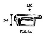
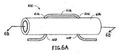
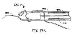
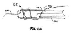
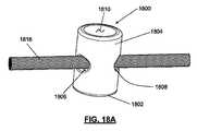
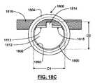
例えば、図3は、プラグ(313)および中空ロック部材(306)を備えるロック要素(305)を含むロックデバイス(301)を示す。中空ロック部材(306)は、デバイスの遠位領域中で管状の細長い部材(303)に解放可能に連結される。細長い部材(303)は、その長さの全体または一部分にわたって可撓性であってもよい。図3に示されるように、中空ロック部材(306)は、細長い部材(303)の遠位延長部の形態である(すなわち、中空ロック部材(306)は、細長い部材(303)の遠位端を超えて延在する)。しかしながら、いくつかの変化例では、ロックデバイスは、細長い部材と、細長い部材に連結されるが、細長い部材の遠位延長部を形成しない、ロック部材とを備えてもよい。再び図3を参照して、中空ロック部材(306)は、細長い部材(303)の外形を維持し、かつ細長い部材と共通壁を共有してもよい。しかし、場合によっては、ロックデバイスは、細長い部材と、外形が細長い部材よりも小さい、または長いロック部材とを備えてもよい。代替として、または加えて、細長い部材およびロック部材は、共通壁を共有しなくてもよい。 For example, FIG. 3 shows a locking device (301) that includes a locking element (305) comprising a plug (313) and a hollow locking member (306). A hollow locking member (306) is releasably connected to a tubular elongate member (303) in the distal region of the device. The elongate member (303) may be flexible over all or a portion of its length. As shown in FIG. 3, the hollow locking member (306) is in the form of a distal extension of the elongated member (303) (ie, the hollow locking member (306) is the distal end of the elongated member (303). Extending beyond). However, in some variations, the locking device may comprise an elongated member and a locking member that is coupled to the elongated member but does not form a distal extension of the elongated member. Referring again to FIG. 3, the hollow locking member (306) may maintain the profile of the elongated member (303) and share a common wall with the elongated member. However, in some cases, the locking device may comprise an elongated member and a locking member having a profile that is smaller or longer than the elongated member. Alternatively or additionally, the elongated member and the locking member may not share a common wall.
図3に示されたデバイスは、カテーテルとして構成されているが、他の構成が使用されてもよい。また、デバイスは、例えば、デバイスが使用される特定の手技の要件に応じて、(例えば、外科的手技で使用するために)拡大または(例えば、低侵襲手技で使用するために)縮小されてもよい。 The device shown in FIG. 3 is configured as a catheter, but other configurations may be used. Also, the device may be expanded (eg, for use in a surgical procedure) or reduced (eg, for use in a minimally invasive procedure), for example, depending on the requirements of the particular procedure in which the device is used. Also good.
図3に示されるように、テザー(310)は、ロックデバイス(301)の遠位領域、特に、中空ロック部材(306)を通される。任意の好適なロック要素がロックデバイスの一部として含まれてもよいが、テザーがプラグとロック部材の壁との間で固定されるように、ロック要素(305)は、プラグ(313)が中空ロック部材(306)の中へ前進させられるとテザーをロックする。示されるように、テザー(310)は、中空ロック部材(306)の壁(312)の中の複数の開口を通される。しかしながら、いくつかの変化例では、テザーが、ロック部材の壁の中の1つだけの開口を通されてもよい。代替として、または加えて、テザーは、ロックデバイスの1つ以上の他の場所で(例えば、ロック要素の遠位で)1つ以上の開口(例えば、通路または穴)を通過してもよい。 As shown in FIG. 3, the tether (310) is threaded through the distal region of the locking device (301), particularly the hollow locking member (306). Any suitable locking element may be included as part of the locking device, but the locking element (305) has a plug (313) so that the tether is secured between the plug and the wall of the locking member. When advanced into the hollow lock member (306), it locks the tether. As shown, the tether (310) is threaded through a plurality of openings in the wall (312) of the hollow locking member (306). However, in some variations, the tether may be passed through only one opening in the wall of the locking member. Alternatively or additionally, the tether may pass through one or more openings (eg, a passage or hole) at one or more other locations of the locking device (eg, distal to the locking element).
ロック要素が固定されるまで、デバイスは、(例えば、摺動することによって)テザーに沿って移動させられてもよく、またはテザーは、デバイスを通して引かれてもよい。したがって、テザーは、テザーの遠位にデバイスを摺動することによって、締め上げ効果を提供するために使用されてもよい。図3に示されたデバイスを通る開口は、デバイスがテザーに沿って依然として容易に摺動することができるように設置されてもよい。いくつかの変化例では、テザーは、図3によって提案されるように、ロック要素の内外に巻装するように、ロック要素の中へ通されてもよい。 The device may be moved along the tether (eg, by sliding) until the locking element is secured, or the tether may be pulled through the device. Thus, the tether may be used to provide a tightening effect by sliding the device distal to the tether. The opening through the device shown in FIG. 3 may be placed so that the device can still slide easily along the tether. In some variations, the tether may be passed through the locking element to wrap around the locking element as suggested by FIG.
いくつかの変化例では、デバイスは、テザーがアンカを通して所望の量だけ引張られるまで、テザーに沿って摺動されてもよく、その時点で、テザーは、ロック要素を使用して適所に固定されてもよい。例えば、上記で説明されるように、図3のテザー(310)は、ロック要素(305)の中空ロック部材(306)にプラグ(313)を押し込むことによって適所に固定されてもよい。図3に示された変化例では、プラグ(313)は、プラグと中空ロック部材(306)の内壁との間でテザーの少なくとも一部分を圧縮することによって、テザー(310)を固定する。 In some variations, the device may be slid along the tether until the tether is pulled through the anchor by the desired amount, at which point the tether is secured in place using a locking element. May be. For example, as described above, the tether (310) of FIG. 3 may be secured in place by pushing the plug (313) into the hollow locking member (306) of the locking element (305). In the variation shown in FIG. 3, the plug (313) secures the tether (310) by compressing at least a portion of the tether between the plug and the inner wall of the hollow locking member (306).
テザーは、例えば、引張デバイスの操作者によって、引張デバイスの1つ以上の構成要素に通されるか、または連結されてもよい。例えば、それを通る1つ以上の開口を有する壁部分を備えるロック部材を通してテザーを通すために、ラッソは、最初に、開口のうちの1つ以上を通されてもよい。次いで、ラッソは、テザーに係合するため、および(ラッソの反対端を引張ることによって)1つまたは複数の開口を通してテザーを通すために使用されてもよい。テザーは、例えば、テザーを把持し、それを1つまたは複数の構成要素に直接連結することによって、テザー引張デバイスのハンドル部分の1つ以上の構成要素に連結されてもよい。例えば、テザーは、把持され、回転可能な引張部材のボビンの切り込みを通して送られ、回転可能な引張部材の軸要素の周囲に巻装されてもよい。いくつかの変化例では、ラッソは、テザー引張デバイス(例えば、ロック要素および/または切断要素を備える)の細長い部材を通してテザーを通すために使用されてもよく、その後、細長い部材から外へ送られ、手で回転可能な引張部材の1つ以上の構成要素と係合されてもよい。 The tether may be threaded or coupled to one or more components of the tensioning device, for example by an operator of the tensioning device. For example, to pass a tether through a locking member that includes a wall portion having one or more openings therethrough, the lasso may first be passed through one or more of the openings. The lasso may then be used to engage the tether and to pass the tether through one or more openings (by pulling the opposite end of the lasso). The tether may be coupled to one or more components of the handle portion of the tether tensioning device, for example, by gripping the tether and coupling it directly to one or more components. For example, the tether may be grasped and fed through a bobbin cut in the rotatable tension member and wrapped around the axial element of the rotatable tension member. In some variations, the lasso may be used to pass the tether through an elongate member of a tether tensioning device (e.g. comprising a locking element and / or a cutting element) and then sent out of the elongate member. , May be engaged with one or more components of a manually rotatable tensioning member.
ロック要素のプラグおよび/または中空ロック部材は、プラグが中空ロック部材から解放される可能性を制限する1つ以上の特徴を備えてもよい。例えば、プラグおよび/または中空ロック部材は、接着剤、糊、またはセメントを含んでもよく、および/または、一旦プラグが中空ロック部材に挿入されると、プラグがロック部材内で保持されるように少なくとも部分的に変形可能であってもよい。一実施例として、プラグは、ロック部材の中へプラグをロックすることに役立つように、圧縮性または弾性である材料を含んでもよい。ある変化例では、プラグは、ロック部材の内面と相互作用する多角形(例えば、六角形)辺を有してもよい。プラグは、中実または中空であってもよい。プラグは、テザーにかかる牽引力を増加させるためにその表面上に段差、くぼみ、リブ、溝、または穴を有してもよい。ロック部材はまた、ロック構成でプラグを担持することに役立つ構造(例えば、周縁、ブラケット等)を含んでもよく、または備えてもよい。いくつかの変化例では、ロック部材自体が、代替として、または加えて、断面が多角形であってもよい。ある変化例では、プラグおよびロック部材は、以下で説明されるように、対応する幾何学形状を有してもよい。デバイスのいくつかの変化例では、プラグおよびロック部材はそれぞれ、ロック部材の中でのプラグの保持を向上させる異なる特徴を含んでもよい。 The plug of the locking element and / or the hollow lock member may comprise one or more features that limit the likelihood that the plug will be released from the hollow lock member. For example, the plug and / or hollow lock member may include an adhesive, glue, or cement, and / or so that once the plug is inserted into the hollow lock member, the plug is retained within the lock member. It may be at least partially deformable. As one example, the plug may include a material that is compressible or elastic to help lock the plug into the locking member. In one variation, the plug may have a polygonal (eg, hexagonal) side that interacts with the inner surface of the locking member. The plug may be solid or hollow. The plug may have steps, indentations, ribs, grooves, or holes on its surface to increase traction on the tether. The locking member may also include or be provided with a structure (eg, rim, bracket, etc.) that helps to carry the plug in a locked configuration. In some variations, the locking member itself may alternatively or in addition be polygonal in cross section. In certain variations, the plug and locking member may have a corresponding geometric shape, as described below. In some variations of the device, the plug and the locking member may each include different features that improve the retention of the plug within the locking member.
図3に示されたデバイスは、中空ロック部材(306)内でテザー(310)を固定するために、適所にプラグ(313)を押し込むためのプッシュ部材(315)をさらに含む。プッシュ部材(図3では棒として示されているが、他の好適な形態のプッシュ部材が使用されてもよい)は、デバイスの管腔内で摺動可能であってもよい。いくつかの変化例では、プッシュ部材は、1つ以上のガイド(例えば、プッシュ部材の方向を誘導する)および/または停止部(例えば、プッシュ部材によって移動させられる距離および/またはプッシュ部材によって印加される力を制限する)を含んでもよい。したがって、プッシュ部材が極端に前方に押されること、または(デバイスの他の部分からのロック要素の分離後に)ロック要素または組織を阻害し得る過剰な力を印加することを防止するために、デバイスおよび/またはプッシュ部材上に運動制限特徴があってもよい。 The device shown in FIG. 3 further includes a push member (315) for pushing the plug (313) in place to secure the tether (310) within the hollow lock member (306). The push member (shown as a rod in FIG. 3 but other suitable forms of push members may be used) may be slidable within the lumen of the device. In some variations, the push member is applied by one or more guides (eg, guiding the direction of the push member) and / or stops (eg, the distance moved by the push member and / or the push member). May be included). Thus, to prevent the push member from being pushed too far forward or applying an excessive force that could interfere with the locking element or tissue (after separation of the locking element from the rest of the device) There may also be motion limiting features on the push member.
上記で説明されるように、ロック要素が、デバイスの他の部分に解放可能に連結されてもよい。任意の適切な方法が、そのような解放可能な連結を提供するために使用されてもよい。いくつかの変化例では、ロック要素(またはその一部分)は、デバイスの他の部分からロック要素を解放するための、分離または断絶することができる領域等の解放可能な連結領域を含んでもよい。一実施例として、ロック要素が、デバイスの他の部分に壊れやすく接続されてもよく、壊れやすい接続を断絶することによってデバイスから分断されてもよい。例えば、ロック要素は、デバイスの別の部分(例えば、細長い部材の遠位部分)に融合されてもよい。融合領域は、デバイスの他の部分からロック要素を分断するために後に断絶されてもよい。融合過程中に印加される熱および/または圧力の量、ならびに融合領域の数およびそれらの場所は、特定の量の力を融合領域に印加してそれらを断絶することができるように選択されてもよい。 As described above, the locking element may be releasably coupled to other parts of the device. Any suitable method may be used to provide such a releasable connection. In some variations, the locking element (or a portion thereof) may include a releasable coupling area, such as an area that can be separated or disconnected, to release the locking element from other parts of the device. As an example, the locking element may be fragilely connected to other parts of the device and may be disconnected from the device by breaking the fragile connection. For example, the locking element may be fused to another portion of the device (eg, the distal portion of the elongate member). The fusion region may later be disconnected to disconnect the locking element from other parts of the device. The amount of heat and / or pressure applied during the fusion process, as well as the number and location of the fusion regions, are selected so that a specific amount of force can be applied to the fusion region to disrupt them. Also good.
ロックデバイスの異なる領域は、異なる材料を含んでもよく、または1つあるいは複数の同じ材料を含んでもよい。いくつかの変化例では、ロックデバイスは、第1の材料で形成されたロック要素と、第2の材料で形成された別の部分と、ロック要素と第3の材料(または材料の組み合わせ)で形成された他の部分との間の融合領域とを備えてもよい。ロックデバイスの異なる領域に異なる材料を使用することは、異なる領域が異なる材料要件を有する場合に有利であってもよい。例えば、デバイスのより遠位の領域が、相対的に可撓性を提供する1つ以上の材料で形成されてもよい一方で、より近位の領域は、相対的に剛性を提供する1つ以上の材料で形成されてもよく、または逆も同様である。また、1つ以上の融合領域と、複数の異なる材料とを含むロックデバイスが説明されているが、ロックデバイスのいくつかの変化例は、融合領域を備えてもよく、かつ完全に1つの材料または材料の組み合わせで形成されてもよく、ロックデバイスの他の変化例は、いずれの融合領域も備えることなく、複数の異なる材料(例えば、2つ、3つ、4つ、または5つの異なる材料)を含んでもよい。 Different regions of the locking device may include different materials or may include one or more of the same materials. In some variations, the locking device comprises a locking element formed of a first material, another portion formed of a second material, and a locking element and a third material (or combination of materials). And a fusion region between the other part formed. Using different materials for different regions of the locking device may be advantageous when the different regions have different material requirements. For example, the more distal region of the device may be formed of one or more materials that provide relatively flexibility, while the more proximal region is one that provides relatively rigidity. It may be formed of the above materials, or vice versa. Also, although a locking device is described that includes one or more fusion regions and a plurality of different materials, some variations of the locking device may comprise a fusion region and are completely one material. Or other combinations of locking devices may be formed of a plurality of different materials (eg, two, three, four, or five different materials without any fusion region). ) May be included.
ある変化例では、ロックデバイスは、構造的に弱体化された領域によってデバイスの他の部分に連結される着脱可能なロック要素を備えてもよい。構造的に弱体化された領域は、例えば、折り目付き、エッチングされた、穿孔性、破砕された、しわ加工された、スロット付き、および/またはくぼみ付きであってもよい。穿孔領域(320)の実施例が図3に示されている。ロック要素は、デバイスの他の部分と同じ材料でできていてもよく、またはロック要素およびデバイスの他の部分は、異なる材料でできていてもよい。十分な量の力が構造的に弱体化した領域に印加されると、ロック要素は、デバイスの他の部分から分離されてもよい。力は、例えば、プッシュ部材または任意の他の好適な機構を使用して、構造的に弱体化された領域に印加されてもよい。 In one variation, the locking device may comprise a removable locking element that is coupled to other parts of the device by structurally weakened areas. The structurally weakened region may be, for example, creased, etched, pierced, crushed, wrinkled, slotted, and / or recessed. An example of a perforated region (320) is shown in FIG. The locking element may be made of the same material as other parts of the device, or the locking element and other parts of the device may be made of different materials. When a sufficient amount of force is applied to the structurally weakened area, the locking element may be separated from other parts of the device. The force may be applied to the structurally weakened area using, for example, a push member or any other suitable mechanism.
いくつかの変化例では、ある量の力の印加が、ロック要素をロックデバイスの別の部分から分断させるために、ロック要素は、少なくとも1つの接着剤および/または摩擦嵌合を介して、ロックデバイスの別の部分に解放可能に連結されてもよい。ロックデバイスの別の部分にロック要素を解放可能に連結する付加的な非限定的方法は、融合、ろう付け、はんだ付け、およびスナップロックを含む。ロックデバイスのいくつかの変化例では、2つ以上の異なる解放可能な連結方法が、相互と併せて使用されてもよい。 In some variations, the application of a certain amount of force causes the locking element to lock via at least one adhesive and / or friction fit so that the locking element is disconnected from another portion of the locking device. It may be releasably coupled to another part of the device. Additional non-limiting methods for releasably coupling the locking element to another portion of the locking device include fusion, brazing, soldering, and snap lock. In some variations of the locking device, two or more different releasable coupling methods may be used in conjunction with each other.
適宜に、ロック要素および/または部材の他の変化例が使用されてもよい。例えば、図4は、プラグ(402)と、プラグ(402)を受容するように構成される管状部材(404)とを備える、ロックデバイス(400)の変化例を示す。管状部材(404)は、それを通る2つの開口(406)および(408)を有する壁部分(410)を備える。2つの開口が示されているが、いくつかの変化例では、管状部材の壁部材は、1つだけの開口、または2つより多くの開口を有してもよい。プラグ(402)および管状部材(404)は、1つまたは複数の同じ材料でできていてもよく、または異なる材料でできていてもよい。いくつかの変化例では、プラグ(402)および/または管状部材(404)は、(例えば、X線透視法下での可視性を提供するために)1つ以上の放射線不透過性材料でできていてもよく、および/または、それらが他の画像診断法下で可視的となることを可能にする1つ以上の材料も含んでもよい。 Other variations of locking elements and / or members may be used as appropriate. For example, FIG. 4 shows a variation of the locking device (400) comprising a plug (402) and a tubular member (404) configured to receive the plug (402). Tubular member (404) comprises a wall portion (410) having two openings (406) and (408) therethrough. Although two openings are shown, in some variations, the wall member of the tubular member may have only one opening, or more than two openings. Plug (402) and tubular member (404) may be made of one or more of the same materials, or may be made of different materials. In some variations, the plug (402) and / or the tubular member (404) can be made of one or more radiopaque materials (eg, to provide visibility under fluoroscopy). And / or one or more materials that allow them to be visible under other diagnostic imaging methods.
テザーが十分に係合されるが、管状部材内で依然として摺動可能であるように、テザーは、いくつかの異なる構成のうちのいずれかで管状部材(404)を通して送られてもよい。(例えば、所望の引張力が印加された後に)テザーをロックするためには、プッシュ部材(図示せず)が、管状部材(404)の中へプラグ(402)を押し進め、それにより、プラグ(402)と管状部材(404)の壁部分(410)との間でテザーを捕捉するために使用されてもよい。 The tether may be fed through the tubular member (404) in any of several different configurations so that the tether is fully engaged but still slidable within the tubular member. To lock the tether (eg, after a desired tensile force is applied), a push member (not shown) pushes the plug (402) into the tubular member (404), thereby causing the plug ( 402) and the wall portion (410) of the tubular member (404) may be used to capture a tether.
上記で説明されるように、いくつかの変化例では、ロック要素が、力を印加することによってデバイスの他の部分から制御可能に分断されてもよい。力は、任意の適切な方式で印加されてもよい。例えば、力は、プッシュ部材を押し進めることによって印加されてもよく、または、水圧力(生理食塩水、水、または同等物を使用する)、磁力、加圧ガス等の形態であってもよい。例えば、プラグ(313)を押し、ロック要素を固定するために使用される、図3の同じプッシュ部材(315)はまた、(例えば、付加的な力でプッシュ部材を押すことによって)デバイスの他の部分からロック要素を分断するために使用されてもよい。いくつかの変化例では、1つの力印加器(例えば、プッシュ部材)がロック要素を固定するために使用されてもよく、別の力印加器(例えば、第2のプッシュ部材)がデバイスの他の部分からロック要素を分断するために使用されてもよい。 As explained above, in some variations, the locking element may be controllably disconnected from other parts of the device by applying a force. The force may be applied in any suitable manner. For example, the force may be applied by pushing the push member, or may be in the form of water pressure (using saline, water, or the like), magnetic force, pressurized gas, and the like. For example, the same push member (315) of FIG. 3 used to push the plug (313) and secure the locking element can also be used by other devices (eg, by pushing the push member with additional force). May be used to decouple the locking element from this portion. In some variations, one force applicator (eg, a push member) may be used to secure the locking element and another force applicator (eg, the second push member) may be used on the other side of the device. May be used to decouple the locking element from this portion.
デバイスの他の部分からロック要素を分断するために必要とされる力の量は、事前設定されてもよい。同じ力印加器(例えば、プッシュ部材、流体ライン、磁石等)が、テザーをロックするため、およびロック要素を分断するための両方に使用される変化例では、ロック要素を分断するために必要とされる力は、ロック要素を固定し、それにより、テザーをロックするために必要とされる力よりも大きくてもよい。例えば、デバイスは、約2lbsより大きい力、約3lbsより大きい力、約4lbsより大きい力、約5lbsより大きい力、約10lbsより大きい力、約20lbsより大きい力、または約2lbsから約5lbsの間の力の印加後に、そのロック要素が分断するために構成されてもよい。ロックデバイスの他の部分からロック要素を分断するために必要とされる力の量は、いくつかの異なる要因のうちのいずれかに依存し得る。そのような要因は、例えば、連結領域の厚さ、連結領域を形成する1つまたは複数の材料、および/または、連結領域中の折り目、穿孔、あるいは他の弱体化した点の場所を含んでもよい。場合によっては、ロックデバイスの他の部分からロック要素を分断するために必要とされる力の量、ならびにロック要素を分断するように力が印加される方法は、ロック要素、テザー、アンカ、および/または周辺組織への損傷を防止するように制御されてもよい。 The amount of force required to disconnect the locking element from other parts of the device may be preset. In variations where the same force applicator (eg, push member, fluid line, magnet, etc.) is used both to lock the tether and to break the locking element, it is necessary to break the locking element. The force exerted may be greater than the force required to secure the locking element and thereby lock the tether. For example, the device may have a force greater than about 2 lbs, a force greater than about 3 lbs, a force greater than about 4 lbs, a force greater than about 5 lbs, a force greater than about 10 lbs, a force greater than about 20 lbs, or between about 2 lbs to about 5 lbs. After application of force, the locking element may be configured to break. The amount of force required to decouple the locking element from other parts of the locking device may depend on any of several different factors. Such factors may include, for example, the thickness of the connecting region, the material or materials that form the connecting region, and / or the location of folds, perforations, or other weakened points in the connecting region. Good. In some cases, the amount of force required to sever the locking element from other parts of the locking device, and the manner in which the force is applied to sever the locking element include the locking element, tether, anchor, and It may be controlled to prevent damage to surrounding tissue.
ロックデバイスの他の部分からロック要素を分断するための力の印加が説明されているが、代替として、または加えて、他の分断方法が採用されてもよい。一実施例として、ロック要素は、例えば、カッターを使用して、ロック要素とデバイスの他の部分との間の接合部を切断することによって分断されてもよい。いくつかの変化例では、カッターは、ロック要素とデバイスの他の部分との間の接合部を剪断するように摺動する剪断ブレードの形態であってもよい。ある変化例では、ロック要素とロックデバイスの他の部分との間の接続を切断するカッターはまた、ロックデバイスによって固定されているテザーを切断するために使用されてもよい。例えば、カッターは、テザーおよび接合部の両方を複合方式で切断してもよく、したがって、テザーが切断された状態でロック要素を完全に解放する。 Although the application of force to sever the locking element from other parts of the locking device has been described, alternatively or in addition, other severing methods may be employed. As an example, the locking element may be broken by cutting the joint between the locking element and the other part of the device, for example using a cutter. In some variations, the cutter may be in the form of a shearing blade that slides to shear the joint between the locking element and the rest of the device. In certain variations, a cutter that breaks the connection between the locking element and other portions of the locking device may also be used to cut a tether that is secured by the locking device. For example, the cutter may cut both the tether and the joint in a combined manner, thus completely releasing the locking element with the tether cut.
ロックデバイスを作動させる(例えば、ロックデバイスを通してテザーを通す、ロックデバイスのロック部材の中へプラグを前進させる等)、および/またはロックデバイスの他の部分からロックデバイスの1つ以上の構成要素を分断するための、ここで説明される方法およびデバイス構成要素のうちのいずれかは、そうすることが好適であれば、ここで説明される他のロックデバイスのうちのいずれかとともに採用されてもよいことを理解されたい。また、ロックデバイスの任意の好適な変化例が、テザー引張デバイスに含まれてもよい。 Activating the locking device (eg, passing the tether through the locking device, advancing the plug into the locking member of the locking device, etc.) and / or one or more components of the locking device from other parts of the locking device Any of the methods and device components described herein for severing may be employed with any of the other locking devices described herein, if appropriate. Please understand that it is good. Also, any suitable variation of the locking device may be included in the tether tensioning device.
場合によっては、ロック要素を備えるテザー引張デバイス、切断要素を備えるテザー引張デバイス、またはロック要素および切断要素の両方を備えるテザー引張デバイス等のデバイスに、テザーを装着することが必要であってもよい。この装着を達成するために、種々の方法および/またはデバイスが使用されてもよい。 In some cases, it may be necessary to attach the tether to a device such as a tether tensioning device with a locking element, a tether tensioning device with a cutting element, or a tether tensioning device with both a locking element and a cutting element. . Various methods and / or devices may be used to accomplish this attachment.
一実施例として、ここで図5Aおよび5Bを参照すると、いくつかの変化例では、テザー(534)は、一方の端にループ(506)を備えるラッソ(lasso)(504)を使用して、デバイス(500)に装着されてもよい。テザー(534)の一方の端は、ラッソ(504)のループ(506)を通される。次いで、ラッソ(504)は、デバイス(500)にテザー(534)を装着するために、デバイス(500)の縦軸に沿って引かれてもよい(図5A)。図5Bに示された代替的実装では、デバイスにテザー(580)を装着するために、ループ(555)を有するラッソ(554)が、デバイス(550)の中の側孔(558)を通して引かれてもよい。デバイス(500)またはデバイス(550)は、ロックおよび/または切断等の1つ以上の機能を果たすために使用されてもよい。ラッソは、例えば、ワイヤ、縫合糸、ケーブル、ひも、またはモノフィラメント等の、従来の材料からできていてもよい。ラッソは、ループ(図5Aおよび5Bに示されるような)、フック、コイル、管、穴を有する細長い要素、またはテザーを「把持」することができる任意の他の構造あるいは材料を備えてもよい。 As one example, referring now to FIGS. 5A and 5B, in some variations, the tether (534) uses a lasso (504) with a loop (506) at one end, It may be attached to the device (500). One end of the tether (534) is passed through the loop (506) of the lasso (504). The lasso (504) may then be pulled along the longitudinal axis of the device (500) to attach the tether (534) to the device (500) (FIG. 5A). In an alternative implementation shown in FIG. 5B, a lasso (554) with a loop (555) is pulled through a side hole (558) in the device (550) to attach a tether (580) to the device. May be. Device (500) or device (550) may be used to perform one or more functions such as locking and / or cutting. The lasso may be made of conventional materials such as, for example, wires, sutures, cables, laces, or monofilaments. The lasso may comprise a loop (as shown in FIGS. 5A and 5B), a hook, a coil, a tube, an elongated element with a hole, or any other structure or material capable of “gripping” a tether. .
ロック要素またはデバイスにテザーを装着するテザー装着デバイスの使用が説明されているが、そのようなテザー装着デバイスは、切断要素もしくはデバイスに、またはロックおよび切断要素またはデバイスの組み合わせにテザーを装着すること等の、他の用途を有してもよい。他の用途も該当してもよい。また、ロック要素またはデバイスに関して本明細書で説明される特徴のうちのいずれかも、適宜に、切断要素もしくはデバイスにおいて、または複合ロックおよび切断要素もしくはデバイスで使用されてもよい。 Although the use of a tether-attached device to attach a tether to a locking element or device is described, such a tether-attaching device attaches a tether to a cutting element or device, or to a combination of a locking and cutting element or device It may have other uses such as. Other uses may also apply. Also, any of the features described herein with respect to the locking element or device may be used in a cutting element or device, as appropriate, or in a combined lock and cutting element or device.
テザーは、いくつかの異なる構成のうちのいずれかで、ロックデバイスまたは切断デバイス等のデバイスを通して送られてもよい。例えば、図6Aおよび6Bは、ロックデバイスの変化例(示されるように、ロックカテーテル(600))を示す。ロックカテーテル(600)は、それに形成される4つの開口(604)、(606)、(608)、および(610)を有する壁(612)を有する管状部材(602)を含む。例えば、テザーの引張力を維持するため、および切断のためにテザーを安定させるために、ロックカテーテル(600)等のロックカテーテルが使用されてもよい。図6Aおよび6Bでは、テザー(614)は、開口(604)、(606)、(608)、および(610)を通して、ロックカテーテル(600)の中へ通されている。テザーは、例えば、上記で説明されるラッソのうちの1つ等のラッソを使用して、ロックカテーテルの中へ通されてもよい。ラッソは、ロックカテーテルの中の開口を通るラッソの操縦性を増進し得る比較的可撓性のループを有してもよい。 The tether may be sent through a device, such as a locking device or a cutting device, in any of several different configurations. For example, FIGS. 6A and 6B show a variation of the locking device (as shown, locking catheter (600)). The locking catheter (600) includes a tubular member (602) having a wall (612) having four openings (604), (606), (608), and (610) formed therein. For example, a locking catheter such as locking catheter (600) may be used to maintain the tether's tensile force and to stabilize the tether for cutting. In FIGS. 6A and 6B, the tether (614) is threaded through the openings (604), (606), (608), and (610) and into the locking catheter (600). The tether may be threaded into the locking catheter using, for example, a lasso such as one of the lassos described above. The lasso may have a relatively flexible loop that can enhance lasso maneuverability through an opening in the locking catheter.
ロックカテーテル(600)は、それを通してテザー(614)が通される4つの開口を含むものとして示されているが、ロックカテーテルは、他の数の開口を含むことができる。例えば、ロックカテーテルのいくつかの変化例が、より少ない開口(例えば、2つの開口)を含んでもよい一方で、ロックカテーテルの他の変化例は、より多くの開口(例えば、6つの開口、8つの開口等)を含んでもよい。ロックカテーテルの中の開口の数が増加するにつれて、開口を通されるテザーの移動の可能性が減少してもよい。 Although the locking catheter (600) is shown as including four openings through which the tether (614) is passed, the locking catheter can include other numbers of openings. For example, some variations of the lock catheter may include fewer openings (eg, two openings), while other variations of the lock catheter may have more openings (eg, six openings, 8 openings). Two openings, etc.). As the number of openings in the locking catheter increases, the likelihood of movement of the tether through the openings may decrease.
ロックデバイスの付加的な実施例が、図7Aおよび7Bに示されている。そこで示されるように、ロックデバイス(700)は、ロック要素(704)に連結される管状の細長い部材(702)を含む。細長い部材(702)は、その壁(708)に切り込まれた連動ロック特徴(706)を有する。連動ロック特徴(706)は、連動ロック特徴を通ってルートが定められた連結線(710)によってロックされて保たれる。連結線(710)が引き出されると、連動ロック特徴(706)が解放され、それにより、細長い部材(702)のフープ強度を限定する。これは、(例えば、ロック要素上の段特徴(図示せず)から係脱することによって)細長い部材をロック要素(704)から分断させる。1つの連結線が示されているが、いくつかの変化例では、連動ロック特徴は、複数の(例えば、2本、3本、4本、または5本の)連結線を使用して、ロックおよび解除されてもよい。いくつかの変化例では、テザー引張デバイスは、テザー引張デバイスに組み込まれたロック要素またはデバイスの連動ロック特徴から連結線を引き出すように(例えば、ボタン摺動部を使用して)作動させられてもよい1つ以上の特徴(例えば、外側部材)を備えてもよい。 Additional examples of locking devices are shown in FIGS. 7A and 7B. As shown there, the locking device (700) includes a tubular elongate member (702) coupled to the locking element (704). The elongate member (702) has an interlocking lock feature (706) cut into its wall (708). The interlock lock feature (706) is locked and held by a connecting line (710) routed through the interlock lock feature. When the connecting line (710) is withdrawn, the interlocking lock feature (706) is released, thereby limiting the hoop strength of the elongated member (702). This causes the elongated member to detach from the locking element (704) (eg, by disengaging from a step feature (not shown) on the locking element). Although one connecting line is shown, in some variations, the interlocking lock feature locks using multiple (eg, two, three, four, or five) connecting lines. And may be released. In some variations, the tether tensioning device is actuated (eg, using a button slide) to draw a connecting line from a locking element incorporated in the tether tensioning device or an interlocking locking feature of the device. One or more features (eg, outer members) may be provided.
図8A−8Cも、ロックデバイスの中の連動ロック特徴を示す。図8A−8Cに示されるように、ロックデバイスの遠位部分(800)は、管状の細長い部材(804)内に配置されるロック管(802)を備える。示されていないが、管状の細長い部材(804)は、例えば、ロックデバイスの他の部分を形成するように付加的な長さにわたって近位に延在してもよく、または、ロックデバイスの他の部分を形成するように別の細長い部材に連結されてもよい。他の構成も使用されてもよい。 8A-8C also show the interlocking lock feature in the locking device. As shown in FIGS. 8A-8C, the distal portion (800) of the locking device comprises a locking tube (802) disposed within a tubular elongate member (804). Although not shown, the tubular elongate member (804) may extend proximally over additional lengths, for example to form other parts of the locking device, or other of the locking device May be coupled to another elongate member to form a portion of Other configurations may also be used.
図8A−8Cに示されるように、2本のNitinol平坦ワイヤ(806)および(808)が、増進した剛性を有する細長い部材を提供するように、細長い部材(804)の壁(810)に埋め込まれる。Nitinolが説明されているが、他の材料が使用されてもよい。また、いくつかの変化例では、ロックデバイスは、平坦ワイヤを含まなくてもよく、または、1本だけの平坦ワイヤ、または2本より多くの平坦ワイヤを含んでもよい。 As shown in FIGS. 8A-8C, two Nitinol flat wires (806) and (808) are embedded in the wall (810) of the elongated member (804) so as to provide an elongated member with increased stiffness. It is. Although Nitinol is described, other materials may be used. Also, in some variations, the locking device may not include a flat wire, or may include only one flat wire, or more than two flat wires.
細長い部材(804)は、その壁(810)に2つの連動ロック特徴を含む。図8A−8Cは、1つだけの連動ロック特徴(812)を示すが、対応する連動ロック特徴は、細長い部材の反対側に位置する。しかしながら、ロックデバイスのいくつかの変化例は、1つだけの連動ロック特徴を含んでもよく、または異なる構成を有する複数の連動ロック特徴を含んでもよい。 The elongate member (804) includes two interlocking locking features on its wall (810). 8A-8C show only one interlocking lock feature (812), the corresponding interlocking lock feature is located on the opposite side of the elongated member. However, some variations of the locking device may include only one interlocking lock feature or may include multiple interlocking lock features having different configurations.
細長い部材(804)の中の連動ロック特徴は、壁(810)に切り込まれたスリットから成るが、異なる種類の連動ロック特徴が可能である。例えば、連動ロック特徴は、多角形の開口部の組み合わせで形成されてもよい。図8Aおよび8Bに示されるように、スリットの両側の壁(810)の部分は、壁(810)の内側の管腔を通って延在する2本のワイヤ(814)および(816)によって結合される(それにより、ロック構成で保たれる)。細長い部材(804)の壁の中の管腔を通って延在するワイヤの使用は、細長い部材が比較的薄型を維持することを可能にしてもよい。ワイヤが説明されているが、任意の他の好適な連結線(例えば、ケーブル、糸、縫合糸、テザー等)が使用されてもよい。また、デバイスのある変化例は、1本だけの連結線、または複数の(例えば、2本、3本、4本、5本)連結線を備えてもよい。複数の連結線を備えるデバイス変化例では、連結線は、同じ種類の連結線であってもよく、または相互に異なってもよい。例えば、デバイスは、ワイヤの形態の1本の連結線と、縫合糸の形態の第2の連結線とを含んでもよい。 The interlocking lock feature in the elongate member (804) consists of a slit cut into the wall (810), although different types of interlocking lock features are possible. For example, the interlock lock feature may be formed by a combination of polygonal openings. As shown in FIGS. 8A and 8B, the portion of the wall (810) on either side of the slit is joined by two wires (814) and (816) that extend through a lumen inside the wall (810). (Thus keeping it in a locked configuration). The use of a wire that extends through a lumen in the wall of the elongate member (804) may allow the elongate member to remain relatively thin. Although wires are described, any other suitable connecting line (eg, cable, thread, suture, tether, etc.) may be used. Also, certain variations of devices may include only one connecting line, or multiple (eg, 2, 3, 4, 5) connecting lines. In device variations with multiple connection lines, the connection lines may be the same type of connection line or may be different from one another. For example, the device may include one connecting line in the form of a wire and a second connecting line in the form of a suture.
ロック管(802)は、(例えば、ロックデバイスのハンドル上のボタン摺動部を使用して)ワイヤ(814)および(816)を引き出し、それにより、連動ロック特徴を解除することによって、細長い部材(804)から分断されてもよい。場合によっては、この解除のみが、細長い部材からロック管を解放することに十分であってもよい。他の場合において、付加的な支援(例えば、プッシュ部材でロック管を押す)が、細長い部材からロック管を解放するために必要とされてもよい。 The lock tube (802) is an elongated member by pulling out the wires (814) and (816) (eg, using a button slide on the handle of the lock device), thereby releasing the interlocking lock feature. (804). In some cases, this release alone may be sufficient to release the lock tube from the elongated member. In other cases, additional assistance (eg, pushing the lock tube with a push member) may be required to release the lock tube from the elongate member.
図9A−9Dは、ロックデバイスの別の変化例を使用して、テザーをロックする方法を図示する。最初に図9Aを参照すると、ロックデバイス(900)は、ロック要素(904)に連結される遠位部分を有する連結管(902)を含む。示されるように、ロック要素(904)は、それを通るテザーの通過のために構成される開口部(905)を有するロック管の形態である。ロック管が示されているが、他の好適な構成がロック要素に使用されてもよい。ロック要素(904)は、例えば、1つ以上の金属、金属合金、および/またはポリマーで形成することができる。一実施例として、いくつかの変化例では、ロック要素(904)は、ナイロンおよび三酸化ビスマス複合材料で形成され、かつPEBAX(登録商標)ポリマーの層を含む。 9A-9D illustrate a method for locking a tether using another variation of a locking device. Referring initially to FIG. 9A, the locking device (900) includes a coupling tube (902) having a distal portion coupled to a locking element (904). As shown, the locking element (904) is in the form of a locking tube having an opening (905) configured for passage of a tether therethrough. Although a locking tube is shown, other suitable configurations may be used for the locking element. The locking element (904) can be formed of, for example, one or more metals, metal alloys, and / or polymers. As an example, in some variations, the locking element (904) is formed of a nylon and bismuth trioxide composite and includes a layer of PEBAX® polymer.
シース(906)は、連結管(902)ならびにロック要素(904)の一部分を包囲する。しかしながら、いくつかの変化例では、シースは、ロック要素の全体を覆ってもよく、ロック要素を超えて遠位に延在さえしてもよい。また、ある変化例では、シースは、連結管の一部分のみを包囲してもよい。シース(906)は、連結管をロック要素に圧迫することによって、連結管(902)をロック要素(904)に連結することに役立つ。加えて、ロック要素(904)は、段部(908)を含み、連結管(902)は、シース(908)が連結管(902)をロック要素(904)に圧迫すると、段部(908)上に引っ掛かるように構成される。示されるように、連結管(902)は、段部(908)に引っ掛かる段部(911)を備える。段部(908)および(911)は、概して角度があるものとして示されているが、いくつかの変化例では、ロック要素段部および/または連結管段部は、傾斜形であってもよく、または任意の他の好適な形状を有してもよい。傾斜形の連結管段部は、例えば、ロック要素からの連結管の比較的容易な分断が所望されるときに、そのような分断を提供してもよい。 The sheath (906) surrounds the connecting tube (902) as well as a portion of the locking element (904). However, in some variations, the sheath may cover the entire locking element and may even extend distally beyond the locking element. In some variations, the sheath may surround only a portion of the connecting tube. The sheath (906) serves to connect the connecting tube (902) to the locking element (904) by pressing the connecting tube against the locking element. In addition, the locking element (904) includes a step (908) that connects to the step (908) when the sheath (908) presses the connection tube (902) against the locking element (904). Configured to hook up. As shown, the connecting tube (902) includes a step (911) that hooks onto the step (908). While the steps (908) and (911) are shown as generally angled, in some variations, the locking element step and / or the connecting tube step may be beveled, Or any other suitable shape. The inclined connecting tube step may provide such a break when, for example, a relatively easy break of the connecting tube from the locking element is desired.
ロックデバイス(900)は、シース(906)が近位に後退させられた場合に、ロック要素(904)が連結管(902)から分断されるように構成される。しかしながら、ある変化例では、シースは、連結管からロック要素を分断するために、連結管およびロック要素が遠位に押し進められている間、近位に後退させられてもよい。代替として、または加えて、連結要素およびロック管は、シースが近位に後退させられる前および/または後に遠位に押されてもよい。連結管からロック要素を分断するための任意の他の好適な方法も採用されてもよい。 The locking device (900) is configured such that the locking element (904) is disconnected from the connecting tube (902) when the sheath (906) is retracted proximally. However, in certain variations, the sheath may be retracted proximally while the connecting tube and locking element are pushed distally to disconnect the locking element from the connecting tube. Alternatively or in addition, the coupling element and the locking tube may be pushed distally before and / or after the sheath is retracted proximally. Any other suitable method for separating the locking element from the connecting tube may also be employed.
図9Aに示されるように、プラグ(910)は、連結管(902)内に配置され、略ミサイル形の構成を有するが、他の適切な構成(例えば、円筒形のプラグ、六角形の断面を有するプラグ等)も使用されてもよい。プラグは、1つ以上のポリマー等の1つまたは複数の任意の適切な材料で形成されてもよく、いくつかの変化例では、比較的剛性であってもよい。ある変化例では、プラグ(910)は、ナイロンおよび三酸化ビスマス複合材料で形成される。図9Aに示されるように、プラグ(910)は、放射線不透過性マーカー(914)を含有する孔(912)を含む。これは、X線蛍光透視法を介したプラグの即時視認を可能にすることができる。プッシュ部材(916)はまた、連結管(902)内に配置され、かつロック要素(904)にプラグ(910)を押し込むために使用されてもよい。 As shown in FIG. 9A, the plug (910) is disposed within the connecting tube (902) and has a generally missile configuration, but other suitable configurations (eg, cylindrical plug, hexagonal cross-section). Or the like having a plug) may also be used. The plug may be formed of one or more of any suitable material, such as one or more polymers, and in some variations may be relatively rigid. In one variation, the plug (910) is formed of nylon and bismuth trioxide composite. As shown in FIG. 9A, the plug (910) includes a hole (912) containing a radiopaque marker (914). This can allow for immediate viewing of the plug via X-ray fluoroscopy. The push member (916) may also be disposed within the connecting tube (902) and used to push the plug (910) into the locking element (904).
ロックデバイス(900)の使用中、テザー(図示せず)が、ロック要素(904)および連結管(902)を通されてもよい。例えば、以下で説明される方法のうちの1つ以上を含む、任意の適切な方法が、テザーを通すために使用されてもよい。一実施例として、ラッソが、テザーの遠位端を捕捉するため、および最初に開口(905)を通して、次いで連結管(902)を通してテザーを通すために使用されてもよい。いくつかの方法では、ロックデバイスは、テザーに沿って所望の位置まで前進させられてもよい。図9Bに示されるように、一旦テザーがロック要素(904)および連結管(902)を通されると、プッシュ部材(916)は、ロックデバイスの遠位端に向かって前進させられてもよい。このプッシュ部材(916)の前進は、ロック要素(904)にプラグ(910)を押し込み、プラグ(910)とロック要素(904)の内壁との間でテザーを圧縮する。連結管(902)がロック要素(904)の段部(908)に係合するため、プラグ前進中に抵抗力が提供される。この抵抗力は、プッシュ部材(916)の前進の結果として、ロック要素(904)が連結管(902)から時期尚早に分断される可能性を制限することに役立ってもよい。ロック要素の遠位端における段(918)は、プラグがロック要素から退出することを防止する。 During use of the locking device (900), a tether (not shown) may be threaded through the locking element (904) and the connecting tube (902). Any suitable method may be used to pass the tether, including, for example, one or more of the methods described below. As one example, a lasso may be used to capture the distal end of the tether and first to pass the tether through the opening (905) and then through the connecting tube (902). In some methods, the locking device may be advanced along the tether to a desired position. As shown in FIG. 9B, once the tether is passed through the locking element (904) and the connecting tube (902), the push member (916) may be advanced toward the distal end of the locking device. . This advancement of the push member (916) pushes the plug (910) into the locking element (904) and compresses the tether between the plug (910) and the inner wall of the locking element (904). Resistance is provided during plug advancement because the connecting tube (902) engages the step (908) of the locking element (904). This resistance may help limit the likelihood that the locking element (904) will be prematurely disconnected from the connecting tube (902) as a result of the advancement of the push member (916). A step (918) at the distal end of the locking element prevents the plug from exiting the locking element.
ここで図9Cを参照すると、プラグ(910)がロック要素(904)に押し込まれた後に、シース(906)が近位に後退させられてもよい。近位に後退させられる前に、シース(906)は、連結管(902)をロック要素(904)に圧迫し、それにより、連結管(902)をロック要素(904)の段部(908)と係合させ、連結管をロック要素に連結する。しかしながら、一旦シース(906)が近位に後退させられると、この圧縮力はもはや存在しなくなる。連結管(902)は、この圧縮力がない場合に、連結管(902)がロック要素(904)の周囲で緊密な嵌合をもはや形成しなくなるように構成される。むしろ、圧縮力の除去は、連結管(902)がより弛緩した構成を成すことを可能にし、本質的に連結管(902)を広げ、それにより、ロック要素(904)の段部(908)から連結管(902)を係脱する。結果として、連結管(902)およびロック要素(904)は、相互から分断される。連結管(902)による、このより弛緩した構成の引受は、連結管の遠位部分の中のスリット(920)の存在、ならびに応力緩和を提供するスリットに沿った2つの開口部(922)および(924)によって増進される。示されていないが、いくつかの変化例では、連結管は、その遠位部分に1つより多くのスリットを含んでもよい。また、開口部(922)および(924)は円形であるが、ある変化例では、連結管は、代替として、または加えて、1つ以上の非円形(例えば、長方形、三角形等)開口部を含んでもよい。 Referring now to FIG. 9C, the sheath (906) may be retracted proximally after the plug (910) is pushed into the locking element (904). Before being retracted proximally, the sheath (906) presses the connecting tube (902) against the locking element (904), thereby causing the connecting tube (902) to step on the locking element (904) (908). To connect the connecting tube to the locking element. However, once the sheath (906) is retracted proximally, this compressive force no longer exists. The connecting tube (902) is configured such that in the absence of this compressive force, the connecting tube (902) no longer forms a tight fit around the locking element (904). Rather, the removal of the compressive force allows the connecting tube (902) to have a more relaxed configuration, essentially widening the connecting tube (902), thereby making the step (908) of the locking element (904). The connecting pipe (902) is disengaged. As a result, the connecting tube (902) and the locking element (904) are disconnected from each other. The undertaking of this more relaxed configuration by the connecting tube (902) is due to the presence of a slit (920) in the distal portion of the connecting tube, and two openings (922) along the slit to provide stress relief and (924). Although not shown, in some variations, the connecting tube may include more than one slit in its distal portion. Also, openings (922) and (924) are circular, but in certain variations, the connecting tube may alternatively or additionally include one or more non-circular (eg, rectangular, triangular, etc.) openings. May be included.
最後に図9Dを参照すると、上記で論議されるように、シース(906)の近位後退が、ロック要素(904)を連結管(902)から解放させる。以前にロック要素(904)に押し込まれたプラグ(910)は、ロック要素(904)とともに解放される。ここで、ロックデバイスの他の構成要素から分離しているロック要素およびプラグが、体内に残り、テザーを固定する一方で、ロックデバイスの他の要素は、身体から除去される。このように、シース(906)は、ロック要素(904)が時期尚早に解放されることを防止し、操作者にロック要素(904)の解放の増進された制御を提供する、安全機構として機能することができる。 Finally, referring to FIG. 9D, as discussed above, the proximal retraction of the sheath (906) releases the locking element (904) from the connecting tube (902). The plug (910) previously pushed into the locking element (904) is released along with the locking element (904). Here, the locking elements and plugs that are separate from the other components of the locking device remain in the body, securing the tether, while the other elements of the locking device are removed from the body. Thus, the sheath (906) functions as a safety mechanism that prevents the locking element (904) from being released prematurely and provides the operator with increased control of the release of the locking element (904). can do.
ロック要素がデバイスに解放可能に連結されてもよい、方法のうちのいくつかしか説明されていないが、スナップ嵌合および他の連結機構(例えば、糸等)を含む、任意の適切な連結部が使用されてもよいことを理解されたい。加えて、本明細書で説明される連結部は、(例えば、超微細手術用途等の、経皮的用途および/またはある外科的用途で使用するための)非常に小さいロック要素を必要としてもよい用途とともに使用するためにも、容易にサイズが縮小されてもよい。デバイスに解放可能に連結されるロック要素は、例えば、その全体で参照することにより以前に組み込まれた、米国特許出願公開第2008/0172035A1号で説明されている。ロック要素の付加的な実施例は、例えば、その全体で参照することにより本明細書に組み込まれる、2009年6月8日出願の米国特許出願第12/480,568号で説明されている。 Although only some of the methods are described in which the locking element may be releasably coupled to the device, any suitable coupling, including snap-fit and other coupling mechanisms (eg, threads, etc.) It should be understood that may be used. In addition, the couplings described herein may require very small locking elements (eg, for use in percutaneous and / or certain surgical applications, such as microsurgical applications). The size may be easily reduced for use with good applications. A locking element that is releasably coupled to a device is described, for example, in US Patent Application Publication No. 2008/0172035 A1, previously incorporated by reference in its entirety. Additional examples of locking elements are described, for example, in US patent application Ser. No. 12 / 480,568 filed Jun. 8, 2009, which is incorporated herein by reference in its entirety.
ロック要素のさらに他の変化例が使用されてもよい。例えば、いくつかの変化例では、ロック要素は、中空ロック部材と、中空ロック部材内で回転するように構成される回転可能なプラグとを備えてもよい。一実施例として、図18A−18Cは、それを通る2つの開口(1806)および(1808)を有する壁部分(1804)を備えるロック管(1802)を備えるロック要素(1800)を示す。ロック管(1802)は、管腔(1810)を有し、その内側に回転可能なプラグ(1812)(これは図18Cに示されるが、一方、図18Aおよび18Bは回転可能なプラグを有しないロック要素を図示している)が配置される。プラグ(1812)は、2つの平面(1813)と(1815)との間に位置する突起(1814)を有する。いくつかの変化例では、突起(1814)は、0.003インチから0.005インチの距離だけ平面(1813)および(1815)から突出してもよい。図18Cに示されるように、プラグ(1812)は、寸法(D1)と、寸法(D1)よりも小さい寸法(D2)とを有する。突起(1814)と、平面(1813)および(1815)とを備える、プラグ(1812)の一部分を除いて、プラグ(1812)の残りの部分は、形状が略円筒形である。しかしながら、任意の他の好適な回転可能なプラグ構成が使用されてもよい。プラグ(1812)が管腔(1810)内に配置され、テザー(1816)が開口(1806)および(1808)を通され、それにより、管腔を横断すると、突起(1814)がテザーに接触する。 Still other variations of the locking element may be used. For example, in some variations, the locking element may comprise a hollow locking member and a rotatable plug configured to rotate within the hollow locking member. As one example, FIGS. 18A-18C show a locking element (1800) comprising a locking tube (1802) comprising a wall portion (1804) having two openings (1806) and (1808) therethrough. Lock tube (1802) has a lumen (1810) and a rotatable plug (1812) inside it (this is shown in FIG. 18C, while FIGS. 18A and 18B do not have a rotatable plug). A locking element is shown). Plug (1812) has a protrusion (1814) located between two planes (1813) and (1815). In some variations, the protrusion (1814) may protrude from the planes (1813) and (1815) by a distance of 0.003 inches to 0.005 inches. As shown in FIG. 18C, the plug (1812) has a dimension (D1) and a dimension (D2) smaller than the dimension (D1). With the exception of a portion of plug (1812) comprising protrusions (1814) and flat surfaces (1813) and (1815), the remaining portion of plug (1812) is generally cylindrical in shape. However, any other suitable rotatable plug configuration may be used. Plug (1812) is placed within lumen (1810) and tether (1816) is threaded through openings (1806) and (1808) so that projection (1814) contacts the tether as it traverses the lumen. .
ここで図18Dおよび18Eを参照すると、プラグ(1812)は、いくつかの変化例では、ロック管(1802)とは別個の構成要素であってもよい。代替として、プラグは、製造中にロック部材に連結されてもよく、またはロック部材と一体的に形成されてもよい。図18Dおよび18Eに示されるように、テザー(1816)は、プラグがロック管の管腔内に未だ配置されていないときに、壁部分(1804)の中の開口(1806)および(1808)を通されてもよい。当然ながら、ある変化例では、テザーは、ロック管の中へのプラグの前進中および/または後に、開口を通されてもよい。示されるように、テザーが管腔に対して中心を外れるように、テザーはロック管の管腔を横断する。しかしながら、いくつかの変化例では、開口は、それらを通過するテザーが管腔の中心を横断するように設置されてもよい。 Referring now to FIGS. 18D and 18E, the plug (1812) may be a separate component from the lock tube (1802) in some variations. Alternatively, the plug may be coupled to the locking member during manufacture or may be integrally formed with the locking member. As shown in FIGS. 18D and 18E, the tether (1816) opens the openings (1806) and (1808) in the wall portion (1804) when the plug is not yet placed in the lumen of the locking tube. May be passed. Of course, in certain variations, the tether may be passed through the opening during and / or after advancement of the plug into the lock tube. As shown, the tether traverses the lumen of the lock tube so that the tether is off-center with respect to the lumen. However, in some variations, the openings may be placed so that the tethers passing through them traverse the center of the lumen.
図18Fに示されるように、テザー(1816)がロック管(1802)の中の開口(1806)および(1808)を通された後、プラグ(1812)上の突起(1814)がテザーに接触するように、プラグ(1812)は、(例えば、プッシュ部材を使用して)ロック管の管腔の中へ前進させられてもよい。典型的には、このロック管の中へのプラグの前進は、後でプラグおよびロック管から引き抜かれ、または別様に除去されてもよい、シースまたは他の細長い部材の少なくとも部分的に内側で行われてもよい。突起がテザーに接触するように、プラグがロック管の中へ嵌合されると、突起とテザーとの間の接触は、相互に対してプラグおよびテザーを定位置で担持することに役立つ、摩擦を提供する(すなわち、プラグとテザーとの間の相対運動を最小化する)。図18Gは、ロック管(1802)内に配置されたときのプラグ(1812)を示す。同様にロック管内に配置されたプラグを示す、図18Cを再び参照すると、プラグ(1812)は、ロック管の内面(1892)と整合可能な湾曲を有する外面(1890)を有する。ここで図18Hを参照すると、テザー(1816)が引張られてもよく、それにより、テザーとプラグ上の突起との間の接触により、(例えば、矢印A2の方向に)ロック管の管腔内でプラグを回転させる。テザーを引張ることにより、概して、テザーが引張られている方向に向かってプラグを回転させる。この回転は、順に、テザーがさらに固定されてもよいように、プラグとテザーとの間でさらなる接触をもたらす。いくつかの変化例では、プラグ(1812)は、約1°(例えば、少なくとも約10°、少なくとも約20°、少なくとも約45°、少なくとも約90°、少なくとも約135°)および/または多くても約180°(例えば、多くても約135°、多くても約90°、多くても約45°、多くても約20°、多くても約10°)回転させられてもよい。 As shown in FIG. 18F, the protrusion (1814) on the plug (1812) contacts the tether after the tether (1816) is passed through the openings (1806) and (1808) in the lock tube (1802). As such, the plug (1812) may be advanced into the lumen of the lock tube (eg, using a push member). Typically, the advancement of the plug into the lock tube is at least partially inside the sheath or other elongate member that may later be withdrawn from the plug and lock tube or otherwise removed. It may be done. When the plug is fitted into the lock tube so that the protrusion contacts the tether, the contact between the protrusion and the tether helps to hold the plug and tether in place relative to each other. (Ie, minimizing relative motion between the plug and the tether). FIG. 18G shows the plug (1812) when placed in the lock tube (1802). Referring again to FIG. 18C, which shows a plug disposed within the lock tube, the plug (1812) has an outer surface (1890) having a curvature that can be aligned with the inner surface (1892) of the lock tube. Referring now to FIG. 18H, the tether (1816) may be pulled, thereby causing contact between the tether and the protrusion on the plug (eg, in the direction of arrow A2) within the lumen of the lock tube. Rotate the plug with. Pulling the tether generally rotates the plug toward the direction in which the tether is being pulled. This rotation in turn provides further contact between the plug and the tether so that the tether may be further secured. In some variations, the plug (1812) is about 1 ° (eg, at least about 10 °, at least about 20 °, at least about 45 °, at least about 90 °, at least about 135 °) and / or at most It may be rotated about 180 ° (eg, at most about 135 °, at most about 90 °, at most about 45 °, at most about 20 °, at most about 10 °).
いくつかの変化例では、比較的低いプラグ力が、プラグ(1812)でロック管(1802)を塞ぐために使用されてもよい。たとえ比較的低いプラグ力が使用される場合があっても、結果として生じるロック力が比較的高い場合がある。したがって、ある変化例では、テザーは、テザーをロックするロック要素に最小限の力を印加することによって、非常にしっかりとロックされてもよい。 In some variations, a relatively low plug force may be used to plug the lock tube (1802) with the plug (1812). Even if a relatively low plug force may be used, the resulting locking force may be relatively high. Thus, in certain variations, the tether may be locked very firmly by applying minimal force to the locking element that locks the tether.
プラグおよび/またはロック部材の他の変化例も使用されてもよい。一実施例として、図18I−18Nは、プラグ(例えば、回転可能なプラグ)を受容して、その間でテザーを固定するように構成される、ロック部材の別の変化例の異なる図を示す。図18Iが、ロック部材(1850)の底面に角度を付けた斜視図を示す一方で、図18Jは、ロック部材(1850)の底面図を示し、図18Kは、ロック部材(1850)の上面に角度を付けた斜視図を示し、図18Lは、ロック部材(1850)の上面図を示し、図18Mは、ロック部材(1850)の正面図を示し、図18Nは、ロック部材(1850)の背面図を示す。図18Jおよび18Lで最も明確に示されるように、ロック部材(1850)は、プラグを受容するように構成される管腔(1852)、ならびにそれを通るテザー(1858)の通過のために構成される2つの開口(1854)および(1856)を有する。ロック部材(1850)の構成は、例えば、ロック部材を通る、比較的制御されたテザー経路指定を提供してもよい。これは順に、使用中にロック部材(1850)が身体組織および/または1つ以上のアンカに対して位置する方法を制御することに役立ってもよい。 Other variations of plugs and / or locking members may also be used. As one example, FIGS. 18I-18N illustrate different views of another variation of a locking member configured to receive a plug (eg, a rotatable plug) and secure a tether therebetween. 18I shows an angled perspective view of the bottom surface of the locking member (1850), while FIG. 18J shows a bottom view of the locking member (1850) and FIG. 18K shows the top surface of the locking member (1850). 18A shows an angled perspective view, FIG. 18L shows a top view of the locking member (1850), FIG. 18M shows a front view of the locking member (1850), and FIG. 18N shows the back of the locking member (1850). The figure is shown. As most clearly shown in FIGS. 18J and 18L, the locking member (1850) is configured for passage of a lumen (1852) configured to receive a plug, as well as a tether (1858) therethrough. Two openings (1854) and (1856). The configuration of the locking member (1850) may provide, for example, a relatively controlled tether routing through the locking member. This in turn may help control the manner in which the locking member (1850) is positioned relative to body tissue and / or one or more anchors during use.
図18Oおよび18Pは、テザーを固定するために使用されてもよい、プラグの別の変化例を示す。いくつかの変化例では、プラグは、(例えば、ロック管の管腔内で)回転可能であってもよい。図18Oおよび18Pに示されるように、プラグ(1870)は、本体(1872)と、本体から延在する階段状構成(1874)の形態である複数の突起(示されるように3つの突起であるが、より多いまたは少ない数の突起も使用されてもよい)とを備える。各突起(1876)、(1878)、および(1880)の半径長さは、前の突起よりも長い。使用中、プラグ(1870)は、(例えば、プッシュ部材で管腔の中へプラグを前進させることによって)ロック管(1884)(図18P)または他のロック部材の管腔(1882)の中へ嵌合されてもよい。プラグが回転させられるにつれて、次第に長い突起が、管腔を横断するテザーに接触していてもよく、管腔内でテザーを固定してもよい。他の構成も使用されてもよい。例えば、いくつかの変化例では、回転可能なプラグは、異なる長さの複数の歯(例えば、各歯が前の歯よりも次第に長い)を備える、歯車形部分を備えてもよい。 18O and 18P show another variation of the plug that may be used to secure the tether. In some variations, the plug may be rotatable (eg, within the lumen of the lock tube). As shown in FIGS. 180 and 18P, the plug (1870) is a plurality of protrusions (three protrusions as shown) in the form of a body (1872) and a stepped configuration (1874) extending from the body. However, a greater or lesser number of protrusions may also be used). The radial length of each protrusion (1876), (1878), and (1880) is longer than the previous protrusion. In use, the plug (1870) is inserted into the lock tube (1884) (FIG. 18P) or other lock member lumen (1882) (eg, by advancing the plug into the lumen with a push member). It may be fitted. As the plug is rotated, progressively longer protrusions may contact the tether that traverses the lumen and may secure the tether within the lumen. Other configurations may also be used. For example, in some variations, the rotatable plug may comprise a gear-shaped portion comprising a plurality of teeth of different lengths (eg, each tooth is progressively longer than the previous tooth).
ある変化例では、ロックデバイスは、上記で説明されるものとは異なる、1つ以上の方法を使用して、テザーをロックしてもよい。1つまたは複数の方法が、回転可能なプラグを回転させ、それにより、テザーをロックするように、テザーを引張ることに加えて、またはその代替案として、使用されてもよい。 In certain variations, the locking device may lock the tether using one or more methods different from those described above. One or more methods may be used in addition to or as an alternative to pulling the tether to rotate the rotatable plug, thereby locking the tether.
例えば、図18Q−18Xは、回転可能なプラグを備えるロック要素の変化例を示し、ロック要素は、テザーをロックするために引張ワイヤ機構を使用する。そこで示されるように、ロック要素(1885)は、略球状ロック部材(1886)と、ロック部材(1886)の管腔(1833)内に配置される、回転可能なプラグまたはカム(1893)と、ロック部材(1886)(図18R)のチャネル(1839)を通過する引張ワイヤ(1889)とを備える。図18Q−18Sは、その解除または開放位置にあるロックデバイス(1885)を図示し、図18V−18Xは、そのロックまたは閉鎖位置にあるロックデバイス(1885)を図示する。 For example, FIGS. 18Q-18X show a variation of a locking element with a rotatable plug, which uses a pull wire mechanism to lock the tether. As shown there, the locking element (1885) includes a generally spherical locking member (1886) and a rotatable plug or cam (1893) disposed within the lumen (1833) of the locking member (1886); A tensioning wire (1889) passing through the channel (1839) of the locking member (1886) (FIG. 18R). 18Q-18S illustrate the locking device (1885) in its unlocked or open position, and FIGS. 18V-18X illustrate the locking device (1885) in its locked or closed position.
使用時に、プラグ(1893)は、ロック部材(1886)の管腔(1833)の中へ前進させられてもよく、テザー(図示せず)は、ロック部材がその解除位置にあるときに、ロック部材を通して送られてもよい。いくつかの変化例では、ロック要素は、ロック部材と、事前に組み立てられる回転可能なプラグとを備えてもよいことに留意されたい。ロック部材(1886)は、それを通るテザーの通過のために構成される、2つの開口(1887)および(1891)を含み、プラグ(1893)はまた、ロック要素がその解除位置にあるときに、テザーの通過のために構成される、スロット(1888)も有する。 In use, the plug (1893) may be advanced into the lumen (1833) of the locking member (1886) and the tether (not shown) locks when the locking member is in its released position. It may be sent through the member. It should be noted that in some variations, the locking element may comprise a locking member and a pre-assembled rotatable plug. The locking member (1886) includes two openings (1887) and (1891) configured for passage of the tether therethrough, and the plug (1893) is also when the locking element is in its released position. It also has a slot (1888) configured for passage of the tether.
テザーがロックデバイス(1885)を通して送られた後に、引張ワイヤ(1889)は、ロック要素(1885)をそのロック位置に移行させるように(例えば、引張ワイヤを引張ることによって)作動させられてもよい。プラグ(1893)は、引張ワイヤ(1889)上の切り込み(1897)(図18R、18S、および18W)に干渉するように構成される、切り込み(1831)(図18U)を含む。より具体的には、引張ワイヤ(1889)が作動させられると、引張ワイヤ(1889)上の切り込み(1897)がプラグ(1893)上の切り込み(1831)に係合し、それにより、プラグ(1893)を回転させる。プラグの回転は、テザーを固定させることに役立つ。加えて、プラグ(1893)は、プラグが回転させられるにつれて、テザーに係合するように構成され、それにより、テザーを定位置でロックすることに役立つ、段(1899)を含む。回転可能なプラグを使用して、および/または任意の他の好適な機構を使用して、テザーをロックするための他の好適なデバイスおよび方法も、適宜に採用されてもよい。テザーロックデバイスは、例えば、その全てが、それらの全体で参照することにより以前に組み込まれた、米国特許出願公開第2006/190030A1号および第2006/0122633A1、ならびに、2009年6月8日出願の米国特許出願第12/480,568号および2009年10月10日出願の米国仮出願第61/104,681号で説明されている。 After the tether is fed through the locking device (1885), the puller wire (1889) may be actuated to transition the lock element (1885) to its locked position (eg, by pulling on the puller wire). . Plug (1893) includes a cut (1831) (FIG. 18U) configured to interfere with cut (1897) (FIGS. 18R, 18S, and 18W) on pull wire (1889). More specifically, when tension wire (1889) is actuated, notch (1897) on tension wire (1889) engages notch (1831) on plug (1893), thereby causing plug (1893). ). The rotation of the plug helps to fix the tether. In addition, the plug (1893) includes a step (1899) that is configured to engage the tether as the plug is rotated, thereby helping to lock the tether in place. Other suitable devices and methods for locking the tether using a rotatable plug and / or using any other suitable mechanism may be employed as appropriate. Tether lock devices are, for example, US Patent Application Publication Nos. 2006 / 190030A1 and 2006 / 0122633A1, all of which have been previously incorporated by reference in their entirety, as well as those filed on June 8, 2009. No. 12 / 480,568 and US Provisional Application No. 61 / 104,681 filed Oct. 10, 2009.
上記で説明されるように、動作中に、テザーを固定的にテザーの長さを固定するために、および/またはテザーが移動することを防止するために、ロック要素が使用されてもよい。テザーがロックされた後、テザーの過剰な長さが切断され、除去されてもよい。着脱可能なロック要素が使用される、いくつかの変化例では、デバイスの残りの部分からロック要素を着脱する前または後に、過剰な材料を除去するように、テザーが切断されてもよい。概して、テザーは、ロック機構の近位で切断されてもよい。多くの場合において、発生し得る滑動を可能にするように、十分な過剰な長さを残しながら、可能な限りロック機構に接近してテザーを切断することが望ましくてもよい。 As described above, a locking element may be used to fix the tether length and / or prevent the tether from moving during operation. After the tether is locked, the excess length of the tether may be cut and removed. In some variations where a detachable locking element is used, the tether may be cut to remove excess material before or after removing the locking element from the rest of the device. In general, the tether may be cut proximal to the locking mechanism. In many cases, it may be desirable to cut the tether as close to the locking mechanism as possible while leaving a sufficient excess length to allow for possible sliding.
ある変化例では、テザーは、切断される前に引張られてもよい。引張は、締め上げ効果を提供してもしなくてもよい。場合によっては、引張は、テザーの一部分をより切断しやすくしてもよい。ある変化例では、単一のデバイスが、テザーの引張および切断の両方を行うために使用されてもよいが、他の変化例では、1つのデバイスがテザーを引張るために使用されてもよく、異なるデバイスがテザーを切断するために使用されてもよい。いくつかの変化例では、異なるデバイスが、テザーの引張、テザーのロック、およびテザーを切断といった機能のそれぞれに使用されてもよい。他の変化例では、1つのデバイスが、上記の機能のうちの少なくとも2つを果たすために使用されてもよく、単一のデバイスが、機能の3つ全てを果たしてもよい。 In some variations, the tether may be pulled before being cut. Tension may or may not provide a tightening effect. In some cases, the tension may make it easier to cut a portion of the tether. In some variations, a single device may be used to both pull and cut the tether, while in other variations, one device may be used to pull the tether, Different devices may be used to cut the tether. In some variations, different devices may be used for each of the functions such as tether pull, tether lock, and cut tether. In other variations, one device may be used to perform at least two of the functions described above, and a single device may perform all three of the functions.
図10Aおよび10Bは、テザーを切断するためにも使用されてもよい、テザー引張デバイス(1000)の変化例を示す。そこで示されるように、テザー引張デバイス(1000)は、細長い部材(1006)に連結されるハンドル部分(1001)を備える。細長い部材(1006)は、少なくとも部分的に外側部材(1090)の管腔内に配置される、内側部材(1011)を備え、例えば、カテーテルの形態であってもよい。ハンドル部分(1001)は、筐体(1003)と、筐体(1003)に連結される回転可能な引張部材(1005)と、筐体(1003)の中のスロット(図示せず)内に配置されるボタン摺動部(1007)および保持器(1008)とを備える。テザー引張デバイス(1000)はさらに、細長い部材(1006)の遠位部分に切断要素(1012)を備える。テザーを引張るために、回転可能な引張部材(1005)は、上記のテザー引張デバイス(200)の回転可能な引張部材(205)と同じように機能する。 FIGS. 10A and 10B show a variation of the tether tensioning device (1000) that may also be used to cut the tether. As shown there, the tether tensioning device (1000) comprises a handle portion (1001) coupled to an elongate member (1006). The elongate member (1006) comprises an inner member (1011) disposed at least partially within the lumen of the outer member (1090) and may be, for example, in the form of a catheter. The handle portion (1001) is disposed in a housing (1003), a rotatable tension member (1005) coupled to the housing (1003), and a slot (not shown) in the housing (1003). A button sliding portion (1007) and a cage (1008). The tether tensioning device (1000) further comprises a cutting element (1012) at the distal portion of the elongate member (1006). To pull the tether, the rotatable tension member (1005) functions in the same manner as the rotatable tension member (205) of the tether tensioning device (200) described above.
回転可能な引張部材(1005)は、引張車輪(1002)と、ボビン(1016)と、圧縮バネ(1018)と、歯車(1020)とを備える。回転可能な引張部材(1005)は、ボビン(1016)に係合されるテザーに引張力を印加するように構成される。引張車輪(1002)および歯車(1020)は、種々の方法でともに連結されてもよい。そこで示されるように、歯車(1020)は、引張車輪(1002)の中の対応する湾入(図示せず)に連結する、長方形の突起(1050)を備えてもよい。代替として、または加えて、歯車および引張車輪は、1つ以上のネジによって連結されてもよく、または1つの連続部品としても製造されてもよい。圧縮バネ(1018)は、引張車輪(1002)およびボビン(1016)が一致して回転することができるように、引張車輪(1002)およびボビン(1016)をともに定着させる。テザーにかかる引張力が、圧縮バネ(1018)によって生成される力を超えるトルク力を生成すると、次いで、テザー引張デバイス(1000)を使用して、テザーがさらに引張られないように、引張車輪(1002)およびボビン(1016)が係脱してもよい。 The rotatable tension member (1005) includes a tension wheel (1002), a bobbin (1016), a compression spring (1018), and a gear (1020). The rotatable tension member (1005) is configured to apply a tensile force to a tether engaged with the bobbin (1016). The tensioning wheel (1002) and the gear (1020) may be coupled together in various ways. As shown there, the gear (1020) may include a rectangular protrusion (1050) that connects to a corresponding bay (not shown) in the tensioning wheel (1002). Alternatively or additionally, the gear and tensioning wheel may be connected by one or more screws, or may be manufactured as one continuous piece. The compression spring (1018) anchors both the tensioning wheel (1002) and the bobbin (1016) so that the tensioning wheel (1002) and the bobbin (1016) can rotate in unison. If the tensile force on the tether produces a torque force that exceeds the force generated by the compression spring (1018), then the tether tensioning device (1000) is used to prevent the tether from being pulled further. 1002) and bobbin (1016) may be disengaged.
テザー引張デバイス(1000)によって引張られているテザーに印加され得る引張力の上限を変化させるために、様々なレベルの剛性を有する圧縮バネが使用されてもよい。圧縮バネを使用することの代替案として、または圧縮バネを使用することに加えて、1つ以上の高摩擦要素が、引張車輪およびボビンを連結するために使用されてもよい。高摩擦要素の1つまたは複数の材料の摩擦係数が、テザーに印加することができる引張力の上限を決定してもよい。 Compression springs with various levels of stiffness may be used to change the upper limit of the tensile force that can be applied to the tether being pulled by the tether tensioning device (1000). As an alternative to using a compression spring or in addition to using a compression spring, one or more high friction elements may be used to connect the tensioning wheel and bobbin. The coefficient of friction of the material or materials of the high friction element may determine the upper limit of tensile force that can be applied to the tether.
ある変化例では、テザー引張デバイス(例えば、1つ以上のロックおよび/または切断要素を備える、またはいずれのロックまたは切断要素も備えない)は、テザーの過度の引張を防止する機構を備えなくてもよい。また、いくつかの変化例では、テザー引張デバイスは、回転可能な引張部材を備えてもよい。ある変化例では、テザー引張デバイスは、以前に圧縮された部材を拡張して、テザーにかかる引張力を調整してもよい、レバーアーム、および/または摺動可能および/または押下可能なボタンを備えてもよい。引張デバイスは、回転可能な引張部材の代替案として、または回転可能な引張部材に加えて、レバーアーム、および/または摺動可能および/または押下可能なボタンを備えてもよい。代替として、または加えて、他の拡張機構が適宜に使用されてもよい。 In some variations, the tether tensioning device (eg, with one or more locking and / or cutting elements, or without any locking or cutting elements) may not have a mechanism to prevent excessive tensioning of the tether. Also good. In some variations, the tether tensioning device may also include a rotatable tensioning member. In one variation, the tether tensioning device includes a lever arm and / or a slidable and / or depressible button that may expand a previously compressed member to adjust the tensile force on the tether. You may prepare. The tensioning device may comprise a lever arm and / or a slidable and / or depressible button as an alternative to or in addition to the rotatable tensioning member. Alternatively or in addition, other expansion mechanisms may be used as appropriate.
引張車輪(1002)、ボビン(1016)、および/または歯車(1020)は、ポリカーボネートおよび/またはABS等の任意の好適な材料でできていてもよい。引張車輪、ボビン、および/または歯車は、同じ材料のうちの1つ以上でできていてもよく、または全て異なる材料でできていてもよい。圧縮バネ(1018)は、ステンレス鋼および/またはコバルトクロム等の、1つまたは複数の任意の好適に剛性の材料でできていてもよい。 The tensioning wheel (1002), bobbin (1016), and / or gear (1020) may be made of any suitable material such as polycarbonate and / or ABS. The tensioning wheel, bobbin, and / or gear may be made of one or more of the same materials, or may all be made of different materials. The compression spring (1018) may be made of one or more of any suitably rigid material, such as stainless steel and / or cobalt chrome.
解放レバー(1004)は、ハンドル部分(1001)の筐体(1003)の中の二重切り込み開口に定着されてもよい。一方の切り込みの中にあるときに、解放レバーは、引張車輪(1002)の双方向連続回転を可能にする。しかしながら、他方の切り込みの中にあるときに、解放レバーは、引張車輪(1002)の一方向離散回転のみを可能にする。ある変化例では、解放レバーは、ハンドル部分筐体から突出しなくてもよく、および/または(例えば、ボタンまたは摺動部によって作動させられる)テザー引張デバイスの内部に位置してもよい。 The release lever (1004) may be anchored in a double cut opening in the housing (1003) of the handle portion (1001). When in one notch, the release lever allows bi-directional continuous rotation of the tensioning wheel (1002). However, when in the other notch, the release lever allows only one-way discrete rotation of the tensioning wheel (1002). In some variations, the release lever may not protrude from the handle portion housing and / or may be located within a tether tensioning device (eg, actuated by a button or slide).
上記で説明されるように、ボタン摺動部(1007)は、ハンドル部分(1001)の筐体(1003)の中のスロット(図示せず)内に配置される。ボタン摺動部(1007)は、それを通る開口(1010)を有する。開口(1010)の直径は、開口(1010)が細長い部材(1006)の内側部材(1011)を受容することを可能にするように選択されてもよい。スロット内のボタン摺動部(1007)の移動が、内側部材(1011)の対応する移動をもたらすように、内側部材は、開口との摩擦嵌合を形成してもよい。ある変化例では、内側部材は、(例えば、1つ以上の接着剤を使用して、および/または熱を印加して内側部材をボタン摺動部に融合することによって)ボタン摺動部(1007)にさらに連結されてもよい。内側部材(1011)は、切断要素(1012)に連結されてもよく、かつテザーを切断するように切断要素を作動させるために使用されてもよい。切断要素の実施例を以下でさらに説明する。 As described above, the button sliding portion (1007) is disposed in a slot (not shown) in the housing (1003) of the handle portion (1001). The button slide (1007) has an opening (1010) therethrough. The diameter of the opening (1010) may be selected to allow the opening (1010) to receive the inner member (1011) of the elongated member (1006). The inner member may form a friction fit with the opening so that movement of the button slide (1007) within the slot results in corresponding movement of the inner member (1011). In some variations, the inner member may be a button slide (1007) (eg, using one or more adhesives and / or by applying heat to fuse the inner member to the button slide). ). Inner member (1011) may be coupled to cutting element (1012) and may be used to actuate the cutting element to cut the tether. Examples of cutting elements are further described below.
図10Cは、保持器(1008)を拡大して詳細に示す。保持器(1008)は、保持器(1008)がボタン摺動部と同じスロット内に配置されるときに、ボタン摺動部(1007)を不動にするように構成される。この不動化は、意図しないボタン摺動部の移動を防止することに役立ってもよい。保持器(1008)は、ボタン摺動部の移動を実質的に阻止する、任意の好適な形状またはサイズであってもよい。保持器は、ポリマー(例えば、ポリカーボネート、ABS)等の、1つまたは複数の任意の好適な材料でできていてもよい。ある変化例では、保持器(1008)は、テザー引張デバイス(1000)の内部にあってもよく、テザー引張デバイスの外面上のボタンまたは摺動部によって作動させられてもよい。いくつかの変化例では、保持器(1008)は、テザーおよび/またはスナップ閉鎖によって、テザー引張デバイス(1000)に係合されてもよい。代替として、または加えて、他の好適な係合機構が使用されてもよい。また、保持器は、上記で論議されるように、1つ以上の他の特徴(例えば、色分け)を有してもよい。 FIG. 10C shows the retainer (1008) in greater detail. The retainer (1008) is configured to immobilize the button slide (1007) when the retainer (1008) is placed in the same slot as the button slide. This immobilization may be useful for preventing unintended movement of the button sliding portion. The retainer (1008) may be any suitable shape or size that substantially prevents movement of the button slide. The cage may be made of one or more any suitable material, such as a polymer (eg, polycarbonate, ABS). In one variation, the retainer (1008) may be internal to the tether tensioning device (1000) and may be actuated by a button or slide on the outer surface of the tether tensioning device. In some variations, the retainer (1008) may be engaged to the tether tensioning device (1000) by a tether and / or snap closure. Alternatively or in addition, other suitable engagement mechanisms may be used. The retainer may also have one or more other features (eg, color coding) as discussed above.
テザーを切断するために、種々の異なる好適な切断要素およびデバイスが使用されてもよい。一実施例として、図11Aは、アンカ(1126)を通って延在するテザー(1100)を切断するために使用されてもよい、切断デバイス(1101)を示す。切断デバイス(1101)は、カテーテル(1105)と、カテーテル(1105)内に配置される管状カッター(1107)とを備える。図11Aに示されるように、テザー(1100)は、ロック要素(1104)によって固定されており、カテーテルの中の側面開口部(1106)を通って退出するように、カテーテル(1105)の中へ通されている。テザー(1100)は、例えば、上記で説明される方法のうちの1つ以上を含む、任意の好適な方法によって、カテーテル(1105)の中へ通すことができる。管状カッター(1107)は、テザーを切断するように十分鋭い、刃(1108)を有する。例えば、管状カッター(1107)は、尖った刃を有する金属管の形態であってもよい。使用中に、可撓性管または棒に取り付けられてもよい、管状カッター(1107)は、管状カッターが側面開口部(1106)上を通過するように、カテーテル(1105)内で前進させられてもよい。管状カッター(1107)がテザー(1100)上で前進させられるにつれて、管状カッター(1107)は、テザーの過剰な部分を削ぎ取る。管状カッター(1107)は形状が管状であるが、カッターの他の構成が使用されてもよい。例えば、カッターは、半管状であってもよく(例えば、半パイプと同様の形状を有する)、または任意の他の好適な構成を有してもよい。いくつかの変化例では、カッターは、管状または半管状でなくてもよい。一実施例として、カッターは、平坦ブレードの形態であってもよい。 A variety of different suitable cutting elements and devices may be used to cut the tether. As one example, FIG. 11A shows a cutting device (1101) that may be used to cut a tether (1100) extending through an anchor (1126). The cutting device (1101) comprises a catheter (1105) and a tubular cutter (1107) disposed within the catheter (1105). As shown in FIG. 11A, the tether (1100) is secured by a locking element (1104) and into the catheter (1105) to exit through the side opening (1106) in the catheter. Has been passed. The tether (1100) can be passed through the catheter (1105) by any suitable method, including, for example, one or more of the methods described above. The tubular cutter (1107) has a blade (1108) that is sharp enough to cut the tether. For example, the tubular cutter (1107) may be in the form of a metal tube having a pointed blade. In use, the tubular cutter (1107), which may be attached to a flexible tube or rod, is advanced within the catheter (1105) such that the tubular cutter passes over the side opening (1106). Also good. As the tubular cutter (1107) is advanced over the tether (1100), the tubular cutter (1107) scrapes off excess portions of the tether. The tubular cutter (1107) is tubular in shape, but other configurations of the cutter may be used. For example, the cutter may be semi-tubular (eg, having a shape similar to a half-pipe) or may have any other suitable configuration. In some variations, the cutter may not be tubular or semi-tubular. As an example, the cutter may be in the form of a flat blade.
いくつかの変化例では、図11Bに示されるように、切断デバイス(1143)は、カテーテル(1145)と、カテーテルの内面上に設置される基部(1149)と、カテーテル内で同心円上に配置される管状カッター(1147)とを備える。カッター(1147)は管状であるが、上記で説明されるように、カッターの他の構成が使用されてもよい。基部(1149)は、例えば、カテーテル(1145)の内面に取り付けられる、またはカテーテル(1145)の内面と一体である、ブロックの形態であってもよい。基部(1149)は、任意のエラストマーまたは剛性材料等の任意の好適な材料で形成することができる。図11Bは、アンカ(1190)を通ってカテーテル(1145)の中へ延在し、かつカテーテル(1145)の中の側面開口部(1146)を通って延在する、テザー(1134)を切断するために使用されている、切断デバイス(1143)を示す。切断される前に、テザー(1134)は、ロック要素(1144)によって定位置で固定される。次いで、管状カッター(1147)は、テザー(1134)を切断するように前進させられる。管状カッター(1147)は、切断テザー(1134)において管状カッター(1147)を支援する、基部(1149)に対して前進させられる。いくつかの変化例では、管状カッター(1147)は、切断を向上させるように転回または回転させることができる。 In some variations, as shown in FIG. 11B, the cutting device (1143) is positioned concentrically within the catheter (1145), a base (1149) placed on the inner surface of the catheter, and the catheter. A tubular cutter (1147). The cutter (1147) is tubular, but other configurations of cutters may be used, as described above. The base (1149) may be in the form of a block, for example, attached to the inner surface of the catheter (1145) or integral with the inner surface of the catheter (1145). The base (1149) can be formed of any suitable material, such as any elastomer or rigid material. FIG. 11B cuts the tether (1134) extending through the anchor (1190) into the catheter (1145) and through the side opening (1146) in the catheter (1145). The cutting device (1143) being used for the purpose is shown. Prior to being cut, the tether (1134) is secured in place by the locking element (1144). The tubular cutter (1147) is then advanced to cut the tether (1134). Tubular cutter (1147) is advanced relative to base (1149), which assists tubular cutter (1147) in cutting tether (1134). In some variations, the tubular cutter (1147) can be turned or rotated to improve cutting.
管状カッターは、任意の好適な切断刃構成を有することができる。例えば、管状カッターは、図11Cの管状カッター(1155)によって例示されるような勾配付き切断刃、図11Dの管状カッター(1156)によって例示されるような尖った外側切断刃、または図11Eの管状カッター(1157)によって例示されるような尖った内側切断刃を有してもよい。加えて、管状カッターは、切断に役立つように、その周囲に鋭い突起の鋸歯状または鋸歯パターンを有してもよい。そのような変化例は、例えば、切断過程中に管状カッターが転回または回転させられるときに、使用されてもよい。 The tubular cutter can have any suitable cutting blade configuration. For example, the tubular cutter may have a beveled cutting blade as illustrated by the tubular cutter (1155) of FIG. 11C, a pointed outer cutting blade as illustrated by the tubular cutter (1156) of FIG. 11D, or the tubular of FIG. 11E. It may have a sharp inner cutting edge as exemplified by cutter (1157). In addition, the tubular cutter may have a serrated or serrated pattern of sharp protrusions around it to aid in cutting. Such a variation may be used, for example, when the tubular cutter is turned or rotated during the cutting process.
いくつかの変化例では、図11Fに示されるように、管状カッター(1160)は、カテーテル(1164)の中の側面開口部(1162)の遠位に設置することができる。次いで、管状カッター(1160)は、ロック要素(1174)によって固定されている、側面開口部(1162)を通って延在するテザー(1170)を切断するように、側面開口部(1162)に向かった近位方向(実線の矢印によって示される)に引かれてもよい。近位にカッターを引くことにより、テザーを切断する比較的容易および/または効率的な方法を提供してもよい。 In some variations, as shown in FIG. 11F, the tubular cutter (1160) can be placed distal to the side opening (1162) in the catheter (1164). The tubular cutter (1160) is then directed toward the side opening (1162) to cut the tether (1170) extending through the side opening (1162) secured by the locking element (1174). It may be drawn in a proximal direction (indicated by a solid arrow). Pulling the cutter proximally may provide a relatively easy and / or efficient way of cutting the tether.
図12は、切断デバイスの別の変化例を示す。そこで示されるように、切断デバイス(1200)は、管腔(1203)を有する管状の細長い部材(1202)と、細長い部材の管腔内に配置されるカッター(1204)とを備える。カッター(1204)は、近位方向に対面する切断ブレード(1206)を有する。細長い部材(1202)は、テザーが細長い部材の管腔を横断するように、それを通してテザー(1214)が通される、2つの開口部(1210)および(1212)を有する、側壁(1208)を備える。2つの側壁開口部が示されているが、デバイスの他の変化例は、3つまたは4つの側壁開口部等の、異なる数の側壁開口部を含んでもよい。テザー(1214)を切断することが所望されるときに、カッター(1204)は、カッター(1204)に取り付けられる引張部材(1216)を使用して、近位に引かれてもよい。これは、切断ブレード(1206)をテザー(1214)に接触させて切断させる。カッター(1204)は、引張部材(1216)を使用して近位に引かれるが、いくつかの変化例では、代替として、または加えて、細長い部材の管腔内に配置されるカッターは、近位方向に押されてもよい。例えば、プッシュ部材は、その遠位端において細長い部材の中へ配置されてもよく、細長い部材の近位端に向かってカッターを押すために使用されてもよい。 FIG. 12 shows another variation of the cutting device. As shown there, the cutting device (1200) comprises a tubular elongated member (1202) having a lumen (1203) and a cutter (1204) disposed within the lumen of the elongated member. The cutter (1204) has a cutting blade (1206) facing proximally. The elongate member (1202) has a sidewall (1208) having two openings (1210) and (1212) through which the tether (1214) is passed so that the tether traverses the lumen of the elongate member. Prepare. Although two sidewall openings are shown, other variations of the device may include a different number of sidewall openings, such as three or four sidewall openings. When it is desired to cut the tether (1214), the cutter (1204) may be pulled proximally using a tension member (1216) attached to the cutter (1204). This causes the cutting blade (1206) to contact the tether (1214) and cut. The cutter (1204) is pulled proximally using the tension member (1216), but in some variations, alternatively or additionally, a cutter disposed within the lumen of the elongate member may be It may be pushed in the lateral direction. For example, the push member may be placed into the elongate member at its distal end and may be used to push the cutter toward the proximal end of the elongate member.
カテーテルと、カテーテルの内部に位置するカッターとを供える、切断デバイスが示されているが、切断デバイスのいくつかの変化例は、カテーテルと、カテーテルの外部に位置する1つ以上のカッターとを含んでもよい。切断デバイスのそのような変化例は、加えて、カテーテルの内部に位置する1つ以上のカッターを含んでも含まなくてもよい。 Although a cutting device is shown that includes a catheter and a cutter located inside the catheter, several variations of the cutting device include a catheter and one or more cutters located outside the catheter. But you can. Such variations of the cutting device may additionally include or not include one or more cutters located within the catheter.
テザーカッターは、任意の適切な構造または材料を備えてもよい。また、上記で説明される管状カッターに加えて、テザーカッターの他の実施例は、熱、電気、化学反応、または同等物によって切断するテザーカッターを含む。例えば、いくつかの変化例では、テザーカッターは、テザーを切断するように、それを通して電気エネルギーが印加される、電極またはフィラメントを備えてもよい。 The tether cutter may comprise any suitable structure or material. In addition to the tubular cutters described above, other embodiments of tether cutters include tether cutters that cut by heat, electricity, chemical reaction, or the like. For example, in some variations, the tether cutter may comprise an electrode or filament through which electrical energy is applied to cut the tether.
ロックデバイスおよび切断デバイスが説明されているが、いくつかの変化例では、単一のデバイスが、ロックおよび切断機能の両方を提供することができる。一実施例として、いくつかの変化例では、テザー引張デバイスは、テザーロック要素およびテザー切断要素の両方を備えてもよい。図13Aおよび13Bは、ロック要素も含むデバイスに組み込まれてもよい、テザーカッターの異なる実施例を図示する。 Although a locking device and a cutting device have been described, in some variations, a single device can provide both locking and cutting functions. As an example, in some variations, the tether tensioning device may comprise both a tether locking element and a tether cutting element. 13A and 13B illustrate different embodiments of a tether cutter that may be incorporated into a device that also includes a locking element.
図13Aは、カテーテルの形態であり、着脱可能なロック要素を備える、デバイス(1301)を示す。デバイスはまた、尖った外側刃(1304)を有する管状テザーカッター(1302)と、カッター(1302)を通過するプッシュ部材(1315)とを含む。デバイス(1301)はさらに、デバイスを通してテザー(1300)を誘導し、切断のためにテザーを設置することができる、ガイドを含む。図13Aに示されるように、テザー(1300)は、(例えば、カッターを遠位に移動させることによって)カッターが前方に運ばれると、カッター(1302)によって容易に切断することができるように、デバイスを通して設置される。図13Aでは、カッター(1302)は、テザーの少なくとも1つの端(例えば、テザーのより近位端に接触する端)がカッターによって切断されるように、(例えば、カッターの円周の半分にわたって)少なくとも1つの刃を有する。 FIG. 13A shows a device (1301) in the form of a catheter and comprising a removable locking element. The device also includes a tubular tether cutter (1302) having a pointed outer blade (1304) and a push member (1315) that passes through the cutter (1302). The device (1301) further includes a guide that can guide the tether (1300) through the device and install the tether for cutting. As shown in FIG. 13A, the tether (1300) can be easily cut by the cutter (1302) when the cutter is carried forward (eg, by moving the cutter distally). Installed through the device. In FIG. 13A, the cutter (1302) is (eg, over half the cutter's circumference) such that at least one end of the tether (eg, the end that contacts the more proximal end of the tether) is cut by the cutter. Having at least one blade.
上記で説明されるように、他の種類のテザーカッターも使用されてもよい。例えば、図13Bは、カッターが近位に後退させられると、テザーを切断するように構成される、同様の管状テザーカッター(1321)を備えるデバイス(1310)を示す。図13Bでは、カッター(1310)は、テザー(1320)が通過し、カッターの少なくとも一部分(1314)が鋭い通路(1312)を有する。テザー(1320)はまた、デバイス(図13Bではカテーテルとして構成されているが、他の好適な構成が使用されてもよい)の壁を通過する。テザーの端は、デバイスのロック要素を固定した後にテザーを張り詰めて引き、次いで、切断されるようにテザーに対してカッターを移動させることによって、切断することができる。 As explained above, other types of tether cutters may also be used. For example, FIG. 13B shows a device (1310) comprising a similar tubular tether cutter (1321) configured to cut the tether when the cutter is retracted proximally. In FIG. 13B, the cutter (1310) has a passage (1312) through which the tether (1320) passes and at least a portion (1314) of the cutter is sharp. The tether (1320) also passes through the wall of the device (configured as a catheter in FIG. 13B, although other suitable configurations may be used). The end of the tether can be cut by tightening and pulling the tether after securing the locking element of the device, and then moving the cutter relative to the tether to be cut.
テザーロック機能およびテザー切断機能の両方を果たすデバイスの付加的な変化例が、使用されてもよい。例えば、ある変化例では、デバイスは、カッターが近位に引かれると(例えば、上記の図12のカッター(1204)のように)テザーを切断するように構成されるテザー、ならびに連動ロック特徴(812)(図8A−8Cに示され、かつそれらを参照して説明される)等の連動ロック特徴を備えるロック要素を備えてもよい。別のロック要素と切断要素との好適な組み合わせも、また、適宜使用され得る。 Additional variations of devices that perform both tether locking and tether cutting functions may be used. For example, in one variation, the device includes a tether that is configured to cut the tether when the cutter is pulled proximally (eg, like the cutter (1204) of FIG. 12 above), as well as an interlocking locking feature ( 812) may include a locking element with interlocking locking features such as (shown in and described with reference to FIGS. 8A-8C). Suitable combinations of other locking elements and cutting elements can also be used as appropriate.
ロックおよび/または切断要素を備える引張デバイスが上記で説明されているが、いくつかの変化例では、別個の引張デバイスならびにロックおよび/または切断デバイスが採用されてもよい。また、ある変化例では、プラグは、引張デバイスは、1つ以上の他の機能を果たしてもよい。一実施例として、引張デバイスは、標的部位に1つ以上の治療薬を送達するために使用されてもよい。 Although tensioning devices with locking and / or cutting elements have been described above, in some variations, separate tensioning devices and locking and / or cutting devices may be employed. Also, in some variations, the plug and the tensioning device may perform one or more other functions. As one example, the tensioning device may be used to deliver one or more therapeutic agents to the target site.
引張、ロック、および切断デバイスおよび方法のある変化例が上記で説明されているが、他の変化例が使用されてもよい。一実施例として、いくつかの変化例では、切断デバイスは、引張力を受けていないテザーを切断するために使用されてもよい。そのような変化例では、テザーは、例えば、切断デバイスの壁に対してテザーを押し進め、テザーを切断するためのバッキングとして壁を使用することによって、切断されてもよい。ロック、切断、および引張デバイスは、その全てが、それらの全体で参照することにより以前に組み込まれた、米国特許出願公開第2006/0190030A1号、第2006/0122633A1、および第2008/0172035A1号で説明されている。 While certain variations of tensioning, locking, and cutting devices and methods have been described above, other variations may be used. As one example, in some variations, a cutting device may be used to cut a tether that is not under tensile force. In such variations, the tether may be cut, for example, by forcing the tether against the wall of the cutting device and using the wall as a backing to cut the tether. The locking, cutting, and tensioning devices are all described in U.S. Patent Application Publication Nos. 2006 / 0193030A1, 2006 / 0122633A1, and 2008 / 0172035A1, all of which have been previously incorporated by reference in their entirety. Has been.
(実施例)
以下の実施例は、心臓弁組織を治療するためのアンカおよび引張デバイスの使用を説明する。これらの実施例は、アンカ、引張デバイス、および関連方法の1つの可能な使用を例示することを目的とするにすぎず、限定的と見なされるべきではない。(Example)
The following example illustrates the use of an anchor and tension device to treat heart valve tissue. These examples are merely intended to illustrate one possible use of anchors, tensioning devices, and related methods and should not be considered limiting.
いくつかの変化例では、ここで説明されるデバイスのうちの1つ以上は、心臓弁機能障害の治療に使用されてもよい。例えば、1つ以上のアンカ送達デバイスが、ガイドトンネルを使用して、弁輪に近接する組織中の標的部位に設置されてもよく、複数の摺動可能に連結されたアンカが、送達デバイスから送達されてもよく、アンカは、弁輪を引き締めるようにともに引かれてもよい。アンカ送達に使用されるデバイスは、1つ以上のアンカを解放可能に収納するための筐体を遠位端またはその付近に有する細長いカテーテル、ならびにアンカ送達デバイスの前進および/または設置を促進するためのガイドデバイスを含んでもよい。デバイスは、筐体が、心室壁、僧帽弁尖、および腱索によって境界される上部左心室内の領域等の、弁輪組織に隣接または接近するように設置されてもよい。ある変化例では、いくつかの異なる構成のうちのいずれかを有する自己固定式アンカが使用されてもよい。繋留されたアンカが標的組織に送達された後に、テザーは、ここで説明されるデバイスのうちのいずれか、または任意の他の好適なデバイスを使用して、引張られ、ロックされ、および/または切断されてもよい。 In some variations, one or more of the devices described herein may be used to treat heart valve dysfunction. For example, one or more anchor delivery devices may be placed at a target site in tissue proximate to the annulus using a guide tunnel, and a plurality of slidably coupled anchors from the delivery device. It may be delivered and the anchor may be pulled together to tighten the annulus. Devices used for anchor delivery include an elongated catheter having a housing at or near its distal end for releasably housing one or more anchors, and to facilitate advancement and / or placement of the anchor delivery device Other guide devices. The device may be placed such that the housing is adjacent or close to the annulus tissue, such as the region in the upper left ventricle bounded by the ventricular wall, mitral valve leaflets, and chordae. In some variations, self-fixing anchors having any of a number of different configurations may be used. After the anchored anchor is delivered to the target tissue, the tether is pulled, locked, and / or using any of the devices described herein, or any other suitable device. It may be cut.
例えば、図14は、右心房(RA)、左心房(LA)、右心室(RV)、および左心室(LV)を含む、心臓(H)の心腔を図示する概略図である。僧帽弁(MV)は、左心房(LA)と左心室(LV)との間の弁であり、僧帽弁尖(MVL)を含む。本明細書で使用されるような弁輪下溝領域(SAG)は、左心室壁の内面、弁尖(MVL)の下面、ならびに心室壁(VW)および弁尖(MVL)に直接接続される三次腱索によって境界される空間を含む。血液は、大動脈(AA)を通って心臓から退出する。 For example, FIG. 14 is a schematic diagram illustrating the heart chamber of the heart (H), including the right atrium (RA), left atrium (LA), right ventricle (RV), and left ventricle (LV). The mitral valve (MV) is the valve between the left atrium (LA) and the left ventricle (LV) and includes the mitral valve leaflet (MVL). The sub-annular groove region (SAG), as used herein, is a tertiary that is directly connected to the inner surface of the left ventricular wall, the lower surface of the leaflet (MVL), and the ventricular wall (VW) and leaflet (MVL). Includes space bounded by chords. Blood exits the heart through the aorta (AA).
図15A−15Iは、異常機能している僧帽弁を修復するための方法の変化例を図示する。そこで示されるように、僧帽弁(MV)は、上方向に見た下方視点から概略的に図示されている。方法の他の変化例では、代替として、または加えて、三尖弁、肺動脈弁、または大動脈弁がアクセスされてもよいことに留意されたい。図15Aを参照すると、例えば、その全体で参照することにより以前に組み込まれた、米国特許出願公開第2009/0222083A1号で説明されているアクセス経路のうちの1つ等の、任意の好適なアクセス経路を使用して、ガイドカテーテル(1540)が弁輪下溝領域(1504)まで前進させられてもよい。ガイドカテーテルは、例えば、その全てが、それらの全体で参照することにより本明細書に組み込まれる、2009年1月20日出願の米国仮出願第61/145,964号、2009年3月16日出願の第61/160,670号、および2009年5月15日出願の第61/178,938号で説明されている。図15Bに示されるように、ガイドカテーテル(1540)が弁輪下溝領域(1504)の中の所望の場所に設置された後に、ガイドワイヤ(1544)がガイドカテーテル(1540)の管腔を通して前進させられる。図15Bに示されるように、ガイドワイヤ(1544)が、弁輪下溝領域(1504)に沿ってガイドカテーテル(1540)よりも遠くに延在するように、ガイドワイヤ(1544)は、ガイドカテーテル(1540)の遠位端(1546)を超えて前進させられてもよい。 15A-15I illustrate a variation of the method for repairing an abnormally functioning mitral valve. As shown there, the mitral valve (MV) is schematically illustrated from a lower viewpoint as viewed upward. Note that in other variations of the method, a tricuspid valve, pulmonary valve, or aortic valve may be accessed alternatively or in addition. Referring to FIG. 15A, any suitable access, such as, for example, one of the access paths described in US Patent Application Publication No. 2009 / 0222083A1, previously incorporated by reference in its entirety. Using the pathway, the guide catheter (1540) may be advanced to the subannular groove region (1504). Guide catheters, for example, US Provisional Application No. 61 / 145,964, filed Jan. 20, 2009, March 16, 2009, all of which are incorporated herein by reference in their entirety. Application No. 61 / 160,670 and Application No. 61 / 178,938 filed May 15, 2009. As shown in FIG. 15B, after the guide catheter (1540) is placed in the desired location in the sub-annular groove region (1504), the guide wire (1544) is advanced through the lumen of the guide catheter (1540). It is done. As shown in FIG. 15B, the guide wire (1544) extends farther than the guide catheter (1540) along the sub-annular groove region (1504). 1540) may be advanced beyond the distal end (1546).
ガイドワイヤ(1544)が弁輪下溝領域(1504)の中に設置された後に、図15Cに示されるように、ガイドトンネルまたはトンネルカテーテル(1548)が、ガイドワイヤ(1544)上でガイドカテーテル(1540)を通して前進させられる。トンネルカテーテル(1548)は、任意の好適なカテーテルであってもよく、場合によっては、図15Cに図示されたトンネルカテーテル等のトンネルカテーテルが、その遠位端において事前成形または事前形成されることが望ましい。いくつかの変化例では、トンネルカテーテル(1548)は、曲線状である事前成形された遠位部分を有してもよい。このように、トンネルカテーテルは、より容易に房室弁の幾何学形状に一致してもよい。また、ここで説明されるカテーテルまたはガイドワイヤのうちのいずれかは、任意の数の好適な曲線、角度、または構成を含むように事前成形または事前形成されてもよいことも理解されたい。当然ながら、ここで説明されるガイドワイヤおよび/またはカテーテルはまた、操縦可能であってもよい。トンネルカテーテル等のカテーテルは、例えば、その全体で参照することにより以前に組み込まれた、米国特許出願公開第2009/0222083A1号で説明されている。 After the guidewire (1544) is placed in the annulus sub-groove region (1504), a guide tunnel or tunnel catheter (1548) is placed over the guidewire (1544) as shown in FIG. 15C. ) The tunnel catheter (1548) may be any suitable catheter, and in some cases, a tunnel catheter, such as the tunnel catheter illustrated in FIG. 15C, may be preformed or preformed at its distal end. desirable. In some variations, the tunnel catheter (1548) may have a pre-shaped distal portion that is curved. In this way, the tunnel catheter may more easily conform to the geometry of the atrioventricular valve. It should also be understood that any of the catheters or guidewires described herein may be preformed or preformed to include any number of suitable curves, angles, or configurations. Of course, the guidewires and / or catheters described herein may also be steerable. Catheters such as tunnel catheters are described, for example, in US Patent Application Publication No. 2009/0222083 A1, previously incorporated by reference in its entirety.
トンネルカテーテル(1548)が弁輪下溝領域(1504)の中に設置された後に、ガイドワイヤ(1544)は、図15Dに示されるように近位に引き出されてもよい。次いで、送達カテーテル(図示せず)が、トンネルカテーテル(1548)の管腔を通り、トンネルカテーテル(1548)の遠位先端(1556)にあるか、またはそれに隣接する開口部(1554)に向かって前進させられる。図15Eで図示された変化例では、送達カテーテルが、トンネルカテーテル(1548)内に残り、アンカ(1558)が、身体組織に付着するように開口部(1554)を通して配備される。しかしながら、他の変化例では、送達カテーテルは、トンネルカテーテル(1548)の開口部(1554)を通して延在させられてもよい。送達カテーテルの例示的な変化例は、例えば、その全体で参照することにより以前に組み込まれた、米国特許出願公開第2009/0222083A1号、ならびに、その両方がそれらの全体で参照することにより本明細書に組み込まれる、2009年3月13日出願の米国仮出願第61/160,230号および2009年5月15日出願の第61/178,910号で説明されている。 After the tunnel catheter (1548) is installed in the subannular groove region (1504), the guide wire (1544) may be withdrawn proximally as shown in FIG. 15D. A delivery catheter (not shown) then passes through the lumen of the tunnel catheter (1548) and is at the distal tip (1556) of the tunnel catheter (1548) or toward the opening (1554) adjacent thereto. Moved forward. In the variation illustrated in FIG. 15E, the delivery catheter remains in the tunnel catheter (1548) and the anchor (1558) is deployed through the opening (1554) to attach to body tissue. However, in other variations, the delivery catheter may be extended through the opening (1554) of the tunnel catheter (1548). Exemplary variations of delivery catheters are described herein, for example, US Patent Application Publication No. 2009 / 0222083A1, previously incorporated by reference in its entirety, and both by reference in their entirety. No. 61 / 160,230, filed Mar. 13, 2009 and 61 / 178,910, filed May 15, 2009, which are incorporated herein by reference.
いくつかの変化例では、開口部(1554)は、トンネルカテーテル(1548)の最遠位アンカ送達開口部であるが、ある変化例では、1つ以上の開口部は、そのような開口部から配備される任意のアンカが、これらの開口部より遠位の後続組織アンカの配備を妨害または制約しないように、トンネルカテーテル(1548)の中に別個の管腔を有してもよい。さらに、図15Eは、トンネルカテーテル(1548)の側面開口部として開口部(1554)を図示するが、いくつかの変化例では、開口部(1554)は、遠位先端(1556)に位置してもよく、かつ図15Cの遠位突出ガイドワイヤ(1544)とともに示された同じ開口部であってもよい。 In some variations, the opening (1554) is the distal-most anchor delivery opening of the tunnel catheter (1548), but in certain variations, one or more openings are from such an opening. Any anchor that is deployed may have a separate lumen in the tunnel catheter (1548) so that it does not interfere with or constrain the deployment of subsequent tissue anchors distal to these openings. Further, FIG. 15E illustrates the opening (1554) as a side opening of the tunnel catheter (1548), but in some variations, the opening (1554) is located at the distal tip (1556). And may be the same opening shown with the distal protruding guidewire (1544) of FIG. 15C.
図15Eに示されたアンカ(1558)は、好ましくは、送達カテーテルおよびトンネルカテーテル(1548)から退出して、弁輪下溝領域(1504)からアクセス可能な弁輪組織の中へ自己固定するような自己拡張設計である。インプラントの1つ以上のアンカが、弁輪の中へ直接配備されてもよい一方で、他のアンカは、弁輪下溝領域(1504)に近接する他の組織に固定されてもよいことを理解されたい。例えば、1つ以上のアンカは、弁輪より下側の組織に固定されてもよい。アンカ(1558)が配備された後に、送達カテーテルが近位に引き出されてもよい。埋込部位に向かって付加的な送達カテーテルの挿入を促進するために、アンカ(1558)に取り付けられ、図15Gおよび15Hで最も良く見られるテザー(1560)が使用されてもよい。 The anchor (1558) shown in FIG. 15E preferably exits the delivery and tunnel catheter (1548) and self-locks into the annulus tissue accessible from the subannular groove region (1504). Self-expanding design. It will be appreciated that one or more anchors of the implant may be deployed directly into the annulus while other anchors may be secured to other tissue proximate to the annulus subgroove region (1504). I want to be. For example, one or more anchors may be secured to tissue below the annulus. After the anchor (1558) is deployed, the delivery catheter may be withdrawn proximally. A tether (1560) attached to the anchor (1558) and best seen in FIGS. 15G and 15H may be used to facilitate insertion of an additional delivery catheter toward the implantation site.
図15Fで明示されるように、この特定の方法の変化例では、トンネルカテーテル(1548)が同じ位置で維持される一方で、付加的なアンカ(1564)および(1558’)が、トンネルカテーテル(1548)に沿った付加的な開口部(1564’)および(1554’)から配備される。いくつかの変化例では、開口部(1564’)および(1554’)を通してアンカ(1564)および(1558’)を連続的に誘導するように、1つ以上の送達カテーテルが、テザー(1560)を使用してトンネルカテーテル(1548)に連続的に挿入されてもよい。ある変化例では、送達カテーテルは、使用時に1つ以上のアンカを装着されてもよいが、他の変化例では、送達カテーテルは、製造時に事前装着されてもよい。送達カテーテルは、また使用時に再装着されてもよく、またはアンカ配備後に廃棄される使い捨てデバイスであってもよい。いくつかの変化例では、送達カテーテルは、2つ以上のアンカ(1558)、(1558’)、および(1564)を担持するように構成されてもよく、アンカ配備の間に送達カテーテルの引出を必要とすることなく、複数のアンカを送達することができる。さらに他の複数アンカ送達カテーテルは、トンネルカテーテル(1548)の複数の開口部を通して複数のアンカを同時に送達するように構成されてもよい。アンカ(1558)、(1558’)、および(1564)は、プッシュ・引張ワイヤ、プランジャ、および/または任意の他の好適な作動技法を含むが、それらに限定されない、任意の好適な様式で、送達カテーテルおよびトンネルカテーテル(1548)から配備されてもよい。同様に、アンカ(1558)、(1558’)、および(1564)は、任意の好適な取付方法によってテザー(1560)に連結されてもよい。例えば、1つ以上の結び目、溶接領域、および/または接着剤が使用されてもよい。アンカ配備およびアンカ取付のための代替変化例は、例えば、その全体で参照することにより以前に組み込まれた、米国特許出願公開第2008/0172035A1号、およびその全体で参照することにより本明細書に組み込まれる、2009年7月17日出願の米国出願第12/505,332号で説明されている。 As demonstrated in FIG. 15F, in this particular method variation, the tunnel catheter (1548) is maintained in the same position, while additional anchors (1564) and (1558 ′) 1548) along additional openings (1564 ') and (1554'). In some variations, one or more delivery catheters may tether (1560) to continuously guide anchors (1564) and (1558 ′) through openings (1564 ′) and (1554 ′). It may be used and inserted continuously into the tunnel catheter (1548). In some variations, the delivery catheter may be fitted with one or more anchors in use, while in other variations, the delivery catheter may be pre-loaded at the time of manufacture. The delivery catheter may also be reattached at the time of use or may be a disposable device that is discarded after anchor deployment. In some variations, the delivery catheter may be configured to carry two or more anchors (1558), (1558 ′), and (1564), withdrawing the delivery catheter during anchor deployment. Multiple anchors can be delivered without the need. Still other multiple anchor delivery catheters may be configured to deliver multiple anchors simultaneously through multiple openings in the tunnel catheter (1548). Anchors (1558), (1558 '), and (1564) in any suitable manner, including but not limited to push and pull wires, plungers, and / or any other suitable actuation technique, It may be deployed from a delivery catheter and a tunnel catheter (1548). Similarly, anchors (1558), (1558 '), and (1564) may be coupled to tether (1560) by any suitable attachment method. For example, one or more knots, weld areas, and / or adhesives may be used. Alternative variations for anchor deployment and anchor mounting are described, for example, in U.S. Patent Application Publication No. 2008 / 0172035A1, previously incorporated by reference in its entirety, and herein by reference in its entirety. Incorporated by reference in US application Ser. No. 12 / 505,332, filed Jul. 17, 2009.
アンカ配備および設置後に、組織を近づけて接合する締め上げ効果を引き起こすようにテザーを引張ることによって、心臓組織の再成形が達成されてもよい。いくつかの変化例では、アンカ配備デバイスが除去されてもよく、テザーは、(例えば、上記で説明される装着ツールのうちの1つ等の装着ツールを使用して)ロック要素および/または切断要素を備えるテザー引張デバイスの中へ通されてもよい。例えば、装着ツールは、ロック要素および/または切断要素を通してテザーを通すために使用されてもよい。その後、テザーは、テザー引張デバイスの1つ以上の引張構成要素に連結されてもよい。例えば、テザーは、テザー引張デバイスの回転可能な引張部材に連結されてもよい。テザーが1つまたは複数の引張構成要素に連結された後に、テザーを近位に後退させることによって、引張力がテザーに印加されてもよい。一変化例では、これは、ボビンの周囲にテザーを巻装し、所望の引張力を提供するようにボビンを回転させることによって達成されてもよい。選択的に、テザーは、手動で、または(例えば、テザー引張デバイス上の)ネジの周囲にテザーを巻装し、ネジを回転させることによって引張られてもよい。ある変化例では、テザー引張力は、所望の量の組織の締め上げを達成するように増加および減少させられてもよい。上記で説明されるように、テザーを過度に引張る(かつ、例えば、心臓組織等の組織を潜在的に損傷する)可能性を制限するために、テザー引張デバイスのある変化例は、テザーが所定の閾値を超えて引張られることを防止する1つ以上の機構を備えてもよい。 After anchor deployment and placement, heart tissue reshaping may be achieved by pulling on the tether to create a clamping effect that brings the tissues closer together. In some variations, the anchor deployment device may be removed and the tether may be locked and / or disconnected (eg, using a mounting tool such as one of the mounting tools described above). It may be passed through a tether tensioning device comprising the element. For example, the mounting tool may be used to pass a tether through a locking element and / or a cutting element. Thereafter, the tether may be coupled to one or more tensioning components of the tether tensioning device. For example, the tether may be coupled to the rotatable tension member of the tether tensioning device. A tensile force may be applied to the tether by retracting the tether proximally after the tether is coupled to the one or more tensile components. In one variation, this may be accomplished by winding a tether around the bobbin and rotating the bobbin to provide the desired tensile force. Optionally, the tether may be pulled manually or by wrapping the tether around a screw (eg, on a tether pulling device) and rotating the screw. In certain variations, the tether tensile force may be increased and decreased to achieve a desired amount of tissue tightening. As described above, to limit the possibility of over-tensioning the tether (and potentially damaging tissue, such as heart tissue), certain variations of the tether tensioning device are One or more mechanisms may be provided to prevent pulling beyond the threshold.
場合によっては、組織へのテザー引張の効果が、生理学的および/または画像フィードバックを使用して、測定または別様に評価されてもよい。ある変化例では、所望の組織の締め上げのレベルが、X線透視法、超音波、エコードップラー等の1つ以上の撮像技法によって決定されてもよい。いくつかの変化例では、僧帽弁逆流の治療において、心エコー専門医が、経食道または経胸壁エコーを使用して、逆流の量へのテザー引張の効果を監視してもよい。経食道または経胸壁エコーは、漏出の最小化に関するフィードバックを提供してもよい。 In some cases, the effect of tether tension on the tissue may be measured or otherwise evaluated using physiological and / or image feedback. In certain variations, the desired level of tissue tightening may be determined by one or more imaging techniques such as fluoroscopy, ultrasound, eccode-pller, and the like. In some variations, in the treatment of mitral regurgitation, an echocardiologist may use transesophageal or transthoracic echoes to monitor the effect of tether tension on the amount of regurgitation. A transesophageal or transthoracic echo may provide feedback regarding leakage minimization.
いくつかの変化例では、種々の寸法またはベクトルに沿って、テザー保持機構を有する複数開口部ガイドトンネルを使用して、心室の再成形が実施されてもよい。例えば、図16を参照すると、ある変化例では、心室または弁の再成形は、直径(B)または弁口の周囲の円周(C)に対して生じてもよい。例えば、直径(B)および円周(C)は、弁輪下溝領域(1604)に対して再成形されてもよい。弁構造の再成形に加えて、再成形は、また、心腔の非弁構造に対しても実施することができる。例えば、心室の直径または円周のうちの1つ以上が再成形されてもよい。図16に示されるように、概して、乳頭筋に、またはそれより上側に位置する心室の直径(B’)および円周(C’)が再成形されてもよい。乳頭筋に、またはそれより下側にある心室の直径(B”)および円周(C”)も、成形されてもよい。再成形または算定される直径および円周の配向は、変化し得るが、いくつかの変化例では、直径または円周は、心室の縦軸に対して略垂直配向であってもよい。当業者であれば、弁口から心腔の頂点まで、または心腔の頂点から心室容量を概して半分に分割する点までの縦軸を含むが、それらに限定されない、縦軸が、いくつかの方法で特徴付けられてもよいことを理解するであろう。同様に、埋込寸法またはベクトルのうちのいくつかはまた、心腔の前後軸または中隔側方軸に対して配向されてもよい。 In some variations, ventricular reshaping may be performed using multiple opening guide tunnels with tether retention features along various dimensions or vectors. For example, referring to FIG. 16, in certain variations, ventricular or valve reshaping may occur relative to diameter (B) or circumference (C) around the valve port. For example, the diameter (B) and circumference (C) may be reshaped relative to the annulus lower groove region (1604). In addition to reshaping the valve structure, reshaping can also be performed on the non-valve structure of the heart chamber. For example, one or more of the ventricular diameter or circumference may be reshaped. As shown in FIG. 16, generally the ventricular diameter (B ') and circumference (C') located at or above the papillary muscles may be reshaped. The diameter (B ") and circumference (C") of the ventricle at or below the papillary muscle may also be shaped. The reshaped or calculated diameter and circumferential orientation may vary, but in some variations, the diameter or circumference may be substantially perpendicular to the longitudinal axis of the ventricle. Those skilled in the art include, but are not limited to, a longitudinal axis from the valve opening to the apex of the heart chamber, or from the apex of the heart chamber to the point that generally divides the ventricular volume in half. It will be appreciated that the method may be characterized. Similarly, some of the implantation dimensions or vectors may also be oriented relative to the anteroposterior or septal lateral axis of the heart chamber.
図17を参照すると、いくつかの変化例では、乳頭筋と弁尖との間のベクトル(A)および(D)に沿った心筋が再成形されてもよい。ベクトル(D)または(A)は、それぞれ、乳頭筋とその関連弁尖との間、または乳頭筋と非関連弁尖との間にあってもよい。図17で図示されたベクトル(A)および(D)は、乳頭筋の先端から示されているが、これらの経路はまた、乳頭筋の基部から算定されてもよい。同様に、弁尖を含む心筋経路が、弁尖の最遠位部、中央、および基部から算定されてもよい。ある変化例では、心臓の再成形は、心腔の頂点と1つ以上の弁との間で生じてもよい。例えば、再成形は、出口弁と心腔の頂点との間のベクトル(E)に沿って、および/または入口弁と頂点との間の経路(F)に沿って生じてもよい。心臓弁修復方法は、例えば、その全体で参照することにより以前に組み込まれた、米国特許出願公開第2009/0222083A1号でさらに説明されている。 Referring to FIG. 17, in some variations, the myocardium along the vectors (A) and (D) between the papillary muscles and leaflets may be reshaped. Vector (D) or (A) may be between the papillary muscle and its associated leaflet, or between the papillary muscle and an unrelated leaflet, respectively. Although the vectors (A) and (D) illustrated in FIG. 17 are shown from the tip of the papillary muscle, these paths may also be calculated from the base of the papillary muscle. Similarly, the myocardial pathway including the leaflets may be calculated from the most distal, middle, and base of the leaflets. In certain variations, heart reshaping may occur between the apex of the heart chamber and one or more valves. For example, reshaping may occur along a vector (E) between the outlet valve and the apex of the heart chamber and / or along a path (F) between the inlet valve and the apex. The heart valve repair method is further described in, for example, US Patent Application Publication No. 2009 / 0222083A1, previously incorporated by reference in its entirety.
キットもここで説明する。いくつかの変化例では、キットは、少なくとも1つのテザー引張デバイスと、少なくとも1つのテザーロックデバイスおよび/またはテザー切断デバイスとを含んでもよい。ある変化例では、キットは、少なくとも1つのテザー切断デバイスと、テザーロック能力も有する少なくとも1つのテザー引張デバイスとを含んでもよく、または、少なくとも1つのテザーロックデバイスと、テザー切断能力も有する少なくとも1つのテザー引張デバイスとを含んでもよい。いくつかの変化例では、キットは、異なる最大テザー引張閾値を有するテザー引張デバイス等の、複数の(例えば、2つ、3つ、4つ、5つ)異なるテザー引張デバイスを含んでもよい。ある変化例では、キットは、1つ以上のアンカ送達デバイスを備えてもよい。当然ながら、使用説明書もキットに提供されてもよい。 The kit is also described here. In some variations, the kit may include at least one tether tensioning device and at least one tether locking device and / or tether cutting device. In certain variations, the kit may include at least one tether cutting device and at least one tether tensioning device that also has tether locking capability, or at least one tether locking device and at least one that also has tether cutting capability. And two tether tensioning devices. In some variations, the kit may include multiple (eg, two, three, four, five) different tether tensioning devices, such as tether tensioning devices having different maximum tether tension thresholds. In certain variations, the kit may include one or more anchor delivery devices. Of course, instructions for use may also be provided in the kit.
方法、デバイス、およびキットが、例示および実施例として、ここでいくらか詳細に説明されているが、そのような例示および実施例は、理解を明確にする目的のためであるにすぎない。本明細書の教示を踏まえて、添付の請求項の精神および範囲から逸脱することなく、ある変更および修正が行われてもよいことが、当業者にとって容易に明白になるであろう。 Although the methods, devices, and kits are described in some detail herein as illustrations and examples, such illustrations and examples are for the purpose of clarity of understanding only. In light of the teachings herein, it will be readily apparent to one skilled in the art that certain changes and modifications may be made without departing from the spirit and scope of the appended claims.
Claims (30)
Translated fromJapaneseハンドル部分であって、
筐体と、
引張車輪を備える回転可能な引張部材と
を備えるハンドル部分を備え、該回転可能な引張部材は、該筐体に連結されており、テザーに係合して該テザーの引張力を増加させる第1の方向、および該テザーの該引張力を減少させる第2の方向に回転するように構成され、該回転可能な引張部材は、該回転可能な引張部材によって係合されるテザーの最大量の引張を提供するロックアウト機構をさらに備える、デバイス。A device for pulling a tether, the device comprising:
A handle part,
A housing,
A rotatable tensioning member comprising a tensioning wheel, the rotatable tensioning member being coupled to the housing and engaging a tether to increase a tensile force of the tether. And a second direction that reduces the tensile force of the tether, wherein the rotatable tension member is the maximum amount of tension of the tether engaged by the rotatable tension member. A device further comprising a lockout mechanism for providing the device.
アンカ送達デバイスと
を備える、キット。A first device for pulling the tether according to claim 1;
An anchor delivery device.
Applications Claiming Priority (5)
| Application Number | Priority Date | Filing Date | Title |
|---|---|---|---|
| US10468608P | 2008-10-10 | 2008-10-10 | |
| US10468108P | 2008-10-10 | 2008-10-10 | |
| US61/104,681 | 2008-10-10 | ||
| US61/104,686 | 2008-10-10 | ||
| PCT/US2009/060227WO2010042857A1 (en) | 2008-10-10 | 2009-10-09 | Tether tensioning devices and related methods |
Publications (1)
| Publication Number | Publication Date |
|---|---|
| JP2012505049Atrue JP2012505049A (en) | 2012-03-01 |
Family
ID=42099572
Family Applications (1)
| Application Number | Title | Priority Date | Filing Date |
|---|---|---|---|
| JP2011531217AWithdrawnJP2012505049A (en) | 2008-10-10 | 2009-10-09 | Tether tensioning device and related methods |
Country Status (9)
| Country | Link |
|---|---|
| US (1) | US8795298B2 (en) |
| EP (1) | EP2349020B1 (en) |
| JP (1) | JP2012505049A (en) |
| KR (1) | KR20110084912A (en) |
| CN (1) | CN102245110A (en) |
| AU (1) | AU2009302181B2 (en) |
| BR (1) | BRPI0919672A2 (en) |
| CA (1) | CA2740245C (en) |
| WO (1) | WO2010042857A1 (en) |
Cited By (2)
| Publication number | Priority date | Publication date | Assignee | Title |
|---|---|---|---|---|
| JP2020509856A (en)* | 2017-03-13 | 2020-04-02 | アースレックス インコーポレイテッド | Surgical fixation systems |
| WO2021251738A1 (en)* | 2020-06-12 | 2021-12-16 | 가톨릭대학교 산학협력단 | Polypectomy snare device having ligating instrument |
Families Citing this family (175)
| Publication number | Priority date | Publication date | Assignee | Title |
|---|---|---|---|---|
| US6488689B1 (en) | 1999-05-20 | 2002-12-03 | Aaron V. Kaplan | Methods and apparatus for transpericardial left atrial appendage closure |
| WO2003105670A2 (en) | 2002-01-10 | 2003-12-24 | Guided Delivery Systems, Inc. | Devices and methods for heart valve repair |
| US9949829B2 (en) | 2002-06-13 | 2018-04-24 | Ancora Heart, Inc. | Delivery devices and methods for heart valve repair |
| US20040243227A1 (en)* | 2002-06-13 | 2004-12-02 | Guided Delivery Systems, Inc. | Delivery devices and methods for heart valve repair |
| US8287555B2 (en)* | 2003-02-06 | 2012-10-16 | Guided Delivery Systems, Inc. | Devices and methods for heart valve repair |
| US7753922B2 (en)* | 2003-09-04 | 2010-07-13 | Guided Delivery Systems, Inc. | Devices and methods for cardiac annulus stabilization and treatment |
| US20050107811A1 (en)* | 2002-06-13 | 2005-05-19 | Guided Delivery Systems, Inc. | Delivery devices and methods for heart valve repair |
| US7883538B2 (en) | 2002-06-13 | 2011-02-08 | Guided Delivery Systems Inc. | Methods and devices for termination |
| US8641727B2 (en) | 2002-06-13 | 2014-02-04 | Guided Delivery Systems, Inc. | Devices and methods for heart valve repair |
| US20060122633A1 (en) | 2002-06-13 | 2006-06-08 | John To | Methods and devices for termination |
| US7846168B2 (en) | 2003-10-09 | 2010-12-07 | Sentreheart, Inc. | Apparatus and method for the ligation of tissue |
| US20050273138A1 (en)* | 2003-12-19 | 2005-12-08 | Guided Delivery Systems, Inc. | Devices and methods for anchoring tissue |
| DE102004040135B3 (en)* | 2004-08-19 | 2005-12-15 | Abg Allgemeine Baumaschinen-Gesellschaft Mbh | Self-propelled device for milling traffic areas |
| US8608797B2 (en) | 2005-03-17 | 2013-12-17 | Valtech Cardio Ltd. | Mitral valve treatment techniques |
| US8333777B2 (en) | 2005-04-22 | 2012-12-18 | Benvenue Medical, Inc. | Catheter-based tissue remodeling devices and methods |
| EP1909655A2 (en) | 2005-06-20 | 2008-04-16 | Sutura, Inc. | Method and apparatus for applying a knot to a suture |
| US8951285B2 (en) | 2005-07-05 | 2015-02-10 | Mitralign, Inc. | Tissue anchor, anchoring system and methods of using the same |
| US20070055206A1 (en)* | 2005-08-10 | 2007-03-08 | Guided Delivery Systems, Inc. | Methods and devices for deployment of tissue anchors |
| US8388680B2 (en)* | 2006-10-18 | 2013-03-05 | Guided Delivery Systems, Inc. | Methods and devices for catheter advancement and delivery of substances therethrough |
| US9883943B2 (en) | 2006-12-05 | 2018-02-06 | Valtech Cardio, Ltd. | Implantation of repair devices in the heart |
| US11259924B2 (en) | 2006-12-05 | 2022-03-01 | Valtech Cardio Ltd. | Implantation of repair devices in the heart |
| US11660190B2 (en) | 2007-03-13 | 2023-05-30 | Edwards Lifesciences Corporation | Tissue anchors, systems and methods, and devices |
| US8246636B2 (en) | 2007-03-29 | 2012-08-21 | Nobles Medical Technologies, Inc. | Suturing devices and methods for closing a patent foramen ovale |
| SI2142107T1 (en) | 2007-03-30 | 2013-05-31 | Sentreheart, Inc. | Devices and systems for closing the left atrial appendage |
| US8790367B2 (en) | 2008-02-06 | 2014-07-29 | Guided Delivery Systems Inc. | Multi-window guide tunnel |
| US8382829B1 (en) | 2008-03-10 | 2013-02-26 | Mitralign, Inc. | Method to reduce mitral regurgitation by cinching the commissure of the mitral valve |
| US8096985B2 (en) | 2008-05-07 | 2012-01-17 | Guided Delivery Systems Inc. | Deflectable guide |
| US8771296B2 (en) | 2008-05-09 | 2014-07-08 | Nobles Medical Technologies Inc. | Suturing devices and methods for suturing an anatomic valve |
| EP2296744B1 (en) | 2008-06-16 | 2019-07-31 | Valtech Cardio, Ltd. | Annuloplasty devices |
| BRPI0920406A2 (en)* | 2008-10-10 | 2019-09-24 | Guided Delivery Systems Inc | termination devices and related methods. |
| US10517719B2 (en) | 2008-12-22 | 2019-12-31 | Valtech Cardio, Ltd. | Implantation of repair devices in the heart |
| US8241351B2 (en) | 2008-12-22 | 2012-08-14 | Valtech Cardio, Ltd. | Adjustable partial annuloplasty ring and mechanism therefor |
| US8911494B2 (en) | 2009-05-04 | 2014-12-16 | Valtech Cardio, Ltd. | Deployment techniques for annuloplasty ring |
| WO2010073246A2 (en) | 2008-12-22 | 2010-07-01 | Valtech Cardio, Ltd. | Adjustable annuloplasty devices and adjustment mechanisms therefor |
| US8147542B2 (en) | 2008-12-22 | 2012-04-03 | Valtech Cardio, Ltd. | Adjustable repair chords and spool mechanism therefor |
| US8715342B2 (en) | 2009-05-07 | 2014-05-06 | Valtech Cardio, Ltd. | Annuloplasty ring with intra-ring anchoring |
| US9011530B2 (en) | 2008-12-22 | 2015-04-21 | Valtech Cardio, Ltd. | Partially-adjustable annuloplasty structure |
| EP2389218A4 (en)* | 2009-01-20 | 2012-06-13 | Guided Delivery Systems Inc | Diagnostic catheters, guide catheters, visualization devices and chord manipulation devices, and related kits and methods |
| WO2010085456A1 (en) | 2009-01-20 | 2010-07-29 | Guided Delivery Systems Inc. | Anchor deployment devices and related methods |
| US8353956B2 (en) | 2009-02-17 | 2013-01-15 | Valtech Cardio, Ltd. | Actively-engageable movement-restriction mechanism for use with an annuloplasty structure |
| AU2010232589B2 (en) | 2009-04-01 | 2014-11-27 | Atricure, Inc. | Tissue ligation devices and controls therefor |
| US9968452B2 (en) | 2009-05-04 | 2018-05-15 | Valtech Cardio, Ltd. | Annuloplasty ring delivery cathethers |
| US11246585B2 (en) | 2009-07-17 | 2022-02-15 | Stryker Puerto Rico Limited | Method and apparatus for attaching tissue to bone, including the provision and use of a novel knotless suture anchor system |
| US10136884B2 (en) | 2009-07-17 | 2018-11-27 | Pivot Medical, Inc. | Method and apparatus for attaching tissue to bone, including the provision and use of a novel knotless suture anchor system, including a retractable sheath |
| US10238379B2 (en) | 2009-07-17 | 2019-03-26 | Pivot Medical, Inc. | Method and apparatus for attaching tissue to bone, including the provision and use of a novel knotless suture anchor system |
| US10426456B2 (en) | 2009-07-17 | 2019-10-01 | Pivot Medical, Inc. | Method and apparatus for re-attaching the labrum to the acetabulum, including the provision and use of a novel suture anchor system |
| US9149268B2 (en) | 2009-07-17 | 2015-10-06 | Pivot Medical, Inc. | Method and apparatus for attaching tissue to bone, including the provision and use of a novel knotless suture anchor system |
| US9179905B2 (en) | 2009-07-17 | 2015-11-10 | Pivot Medical, Inc. | Method and apparatus for re-attaching the labrum to the acetabulum, including the provision and use of a novel suture anchor system |
| US12232718B2 (en) | 2009-07-17 | 2025-02-25 | Stryker Puerto Rico Limited | Method and apparatus for attaching tissue to bone, including the provision and use of a novel knotless suture anchor system |
| US11197663B2 (en) | 2009-07-17 | 2021-12-14 | Stryker Puerto Rico Limited | Method and apparatus for attaching tissue to bone, including the provision and use of a novel knotless suture anchor system |
| US10058319B2 (en) | 2009-07-17 | 2018-08-28 | Pivot Medical, Inc. | Method and apparatus for attaching tissue to bone, including the provision and use of a novel knotless suture anchor system, including a novel locking element |
| US9180007B2 (en) | 2009-10-29 | 2015-11-10 | Valtech Cardio, Ltd. | Apparatus and method for guide-wire based advancement of an adjustable implant |
| US9011520B2 (en) | 2009-10-29 | 2015-04-21 | Valtech Cardio, Ltd. | Tissue anchor for annuloplasty device |
| US10098737B2 (en) | 2009-10-29 | 2018-10-16 | Valtech Cardio, Ltd. | Tissue anchor for annuloplasty device |
| US8734467B2 (en) | 2009-12-02 | 2014-05-27 | Valtech Cardio, Ltd. | Delivery tool for implantation of spool assembly coupled to a helical anchor |
| US8870950B2 (en) | 2009-12-08 | 2014-10-28 | Mitral Tech Ltd. | Rotation-based anchoring of an implant |
| AU2011241103A1 (en) | 2010-04-13 | 2012-11-08 | Sentreheart, Inc. | Methods and devices for treating atrial fibrillation |
| US11653910B2 (en) | 2010-07-21 | 2023-05-23 | Cardiovalve Ltd. | Helical anchor implantation |
| WO2012031204A2 (en) | 2010-09-03 | 2012-03-08 | Guided Delivery Systems Inc. | Devices and methods for anchoring tissue |
| EP2688516B1 (en) | 2011-03-21 | 2022-08-17 | Cephea Valve Technologies, Inc. | Disk-based valve apparatus |
| EP3644194B1 (en) | 2011-04-15 | 2022-12-07 | Heartstitch, Inc. | Suturing devices for suturing an anatomic valve |
| ES2671928T3 (en) | 2011-06-08 | 2018-06-11 | Sentreheart, Inc. | Tissue ligation devices and tension devices for them |
| US9918840B2 (en) | 2011-06-23 | 2018-03-20 | Valtech Cardio, Ltd. | Closed band for percutaneous annuloplasty |
| EP3345573B1 (en) | 2011-06-23 | 2020-01-29 | Valtech Cardio, Ltd. | Closure element for use with annuloplasty structure |
| US10792152B2 (en) | 2011-06-23 | 2020-10-06 | Valtech Cardio, Ltd. | Closed band for percutaneous annuloplasty |
| CN103917183A (en) | 2011-06-29 | 2014-07-09 | 皮沃特医疗公司 | Method and apparatus for re-attaching the labrum to the acetabulum, including the provision and use of a novel suture anchor system |
| US8858623B2 (en) | 2011-11-04 | 2014-10-14 | Valtech Cardio, Ltd. | Implant having multiple rotational assemblies |
| EP3656434B1 (en) | 2011-11-08 | 2021-10-20 | Valtech Cardio, Ltd. | Controlled steering functionality for implant-delivery tool |
| EP2881083B1 (en) | 2011-12-12 | 2017-03-22 | David Alon | Heart valve repair device |
| US9345465B2 (en) | 2012-01-13 | 2016-05-24 | Dallen Medical, Inc. | Actuator for band tensioning system |
| US9706988B2 (en) | 2012-05-11 | 2017-07-18 | Heartstitch, Inc. | Suturing devices and methods for suturing an anatomic structure |
| US9445899B2 (en)* | 2012-08-22 | 2016-09-20 | Joseph M. Arcidi | Method and apparatus for mitral valve annuloplasty |
| US9216018B2 (en) | 2012-09-29 | 2015-12-22 | Mitralign, Inc. | Plication lock delivery system and method of use thereof |
| WO2014064694A2 (en) | 2012-10-23 | 2014-05-01 | Valtech Cardio, Ltd. | Controlled steering functionality for implant-delivery tool |
| EP2911593B1 (en) | 2012-10-23 | 2020-03-25 | Valtech Cardio, Ltd. | Percutaneous tissue anchor techniques |
| WO2014087402A1 (en) | 2012-12-06 | 2014-06-12 | Valtech Cardio, Ltd. | Techniques for guide-wire based advancement of a tool |
| US20150351906A1 (en) | 2013-01-24 | 2015-12-10 | Mitraltech Ltd. | Ventricularly-anchored prosthetic valves |
| EP2961351B1 (en) | 2013-02-26 | 2018-11-28 | Mitralign, Inc. | Devices for percutaneous tricuspid valve repair |
| BR112015019887A2 (en) | 2013-03-12 | 2017-07-18 | Sentreheart Inc | device for closing a target tissue |
| US10449333B2 (en) | 2013-03-14 | 2019-10-22 | Valtech Cardio, Ltd. | Guidewire feeder |
| CN105283214B (en) | 2013-03-15 | 2018-10-16 | 北京泰德制药股份有限公司 | Translate conduit, system and its application method |
| US10292694B2 (en) | 2013-04-22 | 2019-05-21 | Pivot Medical, Inc. | Method and apparatus for attaching tissue to bone |
| WO2015002815A1 (en) | 2013-07-02 | 2015-01-08 | Med-Venture Investments, Llc | Suturing devices and methods for suturing an anatomic structure |
| CA2917573A1 (en)* | 2013-07-11 | 2015-01-15 | Shifamed Holdings, Llc | Devices and methods for lung volume reduction |
| US8870948B1 (en) | 2013-07-17 | 2014-10-28 | Cephea Valve Technologies, Inc. | System and method for cardiac valve repair and replacement |
| US10070857B2 (en) | 2013-08-31 | 2018-09-11 | Mitralign, Inc. | Devices and methods for locating and implanting tissue anchors at mitral valve commissure |
| US10300286B2 (en) | 2013-09-27 | 2019-05-28 | Medtronic, Inc. | Tools and assemblies thereof for implantable medical devices |
| US9526522B2 (en) | 2013-09-27 | 2016-12-27 | Medtronic, Inc. | Interventional medical systems, tools, and assemblies |
| WO2015059699A2 (en) | 2013-10-23 | 2015-04-30 | Valtech Cardio, Ltd. | Anchor magazine |
| EP4226881A1 (en) | 2013-10-31 | 2023-08-16 | AtriCure, Inc. | Device for left atrial appendage closure |
| JP6469109B2 (en) | 2013-12-06 | 2019-02-13 | メッド − ベンチャー インベストメンツ、エルエルシー | Suture method and apparatus |
| AU2014362199B2 (en) | 2013-12-12 | 2019-07-11 | Stryker Puerto Rico Limited | Method and apparatus for attaching tissue to bone, including the provision and use of a novel knotless suture anchor system |
| US9610162B2 (en) | 2013-12-26 | 2017-04-04 | Valtech Cardio, Ltd. | Implantation of flexible implant |
| US10178993B2 (en) | 2014-07-11 | 2019-01-15 | Cardio Medical Solutions, Inc. | Device and method for assisting end-to-side anastomosis |
| EP3174502B1 (en) | 2014-07-30 | 2022-04-06 | Cardiovalve Ltd | Apparatus for implantation of an articulatable prosthetic valve |
| US10478620B2 (en) | 2014-08-26 | 2019-11-19 | Medtronic, Inc. | Interventional medical systems, devices, and methods of use |
| US9675798B2 (en) | 2014-08-26 | 2017-06-13 | Medtronic, Inc. | Interventional medical systems, devices, and components thereof |
| EP3922213A1 (en) | 2014-10-14 | 2021-12-15 | Valtech Cardio, Ltd. | Leaflet-restraining techniques |
| CN104274220B (en)* | 2014-10-22 | 2017-01-18 | 陕西福泰医疗科技有限公司 | Fastening device for memory alloy suture line |
| US9414857B2 (en) | 2014-11-20 | 2016-08-16 | Medtronic, Inc. | Delivery system assemblies for implantable medical devices |
| WO2016093877A1 (en) | 2014-12-09 | 2016-06-16 | Cephea Valve Technologies, Inc. | Replacement cardiac valves and methods of use and manufacture |
| CN104490442B (en)* | 2014-12-31 | 2016-08-24 | 东莞市南城医院 | A kind of abdominal cavity accurate operation looping and binding device for scope |
| CN110141399B (en) | 2015-02-05 | 2021-07-27 | 卡迪尔维尔福股份有限公司 | Prosthetic valve with axial sliding frame |
| US20160256269A1 (en) | 2015-03-05 | 2016-09-08 | Mitralign, Inc. | Devices for treating paravalvular leakage and methods use thereof |
| US10058321B2 (en) | 2015-03-05 | 2018-08-28 | Ancora Heart, Inc. | Devices and methods of visualizing and determining depth of penetration in cardiac tissue |
| US9936956B2 (en) | 2015-03-24 | 2018-04-10 | Sentreheart, Inc. | Devices and methods for left atrial appendage closure |
| ES2972395T3 (en) | 2015-03-24 | 2024-06-12 | Atricure Inc | Tissue ligation devices |
| CN107847320B (en) | 2015-04-30 | 2020-03-17 | 瓦尔泰克卡迪欧有限公司 | Valvuloplasty techniques |
| AU2016260305B2 (en) | 2015-05-12 | 2022-01-06 | Ancora Heart, Inc. | Device and method for releasing catheters from cardiac structures |
| EP3294220B1 (en)* | 2015-05-14 | 2023-12-06 | Cephea Valve Technologies, Inc. | Cardiac valve delivery devices and systems |
| WO2018136959A1 (en) | 2017-01-23 | 2018-07-26 | Cephea Valve Technologies, Inc. | Replacement mitral valves |
| AU2016262564B2 (en) | 2015-05-14 | 2020-11-05 | Cephea Valve Technologies, Inc. | Replacement mitral valves |
| CN104939950B (en)* | 2015-06-28 | 2017-04-12 | 武忠 | Coil winding and unwinding device for artificial tendinous cord |
| US10751182B2 (en) | 2015-12-30 | 2020-08-25 | Edwards Lifesciences Corporation | System and method for reshaping right heart |
| US10828160B2 (en) | 2015-12-30 | 2020-11-10 | Edwards Lifesciences Corporation | System and method for reducing tricuspid regurgitation |
| US10531866B2 (en) | 2016-02-16 | 2020-01-14 | Cardiovalve Ltd. | Techniques for providing a replacement valve and transseptal communication |
| EP4331509A3 (en) | 2016-02-26 | 2024-05-15 | AtriCure, Inc. | Devices for left atrial appendage closure |
| WO2017180092A1 (en) | 2016-04-11 | 2017-10-19 | Nobles Medical Technologies Ii, Inc. | Suture spools for tissue suturing device |
| US10143823B2 (en) | 2016-04-29 | 2018-12-04 | Medtronic, Inc. | Interventional medical systems and improved assemblies thereof and associated methods of use |
| US10702274B2 (en) | 2016-05-26 | 2020-07-07 | Edwards Lifesciences Corporation | Method and system for closing left atrial appendage |
| WO2017218877A1 (en)* | 2016-06-17 | 2017-12-21 | Cephea Valve Technologies, Inc. | Cardiac valve delivery devices and systems |
| GB201611910D0 (en) | 2016-07-08 | 2016-08-24 | Valtech Cardio Ltd | Adjustable annuloplasty device with alternating peaks and troughs |
| US20190231525A1 (en) | 2016-08-01 | 2019-08-01 | Mitraltech Ltd. | Minimally-invasive delivery systems |
| CA3031187A1 (en) | 2016-08-10 | 2018-02-15 | Cardiovalve Ltd. | Prosthetic valve with concentric frames |
| US10667914B2 (en) | 2016-11-18 | 2020-06-02 | Ancora Heart, Inc. | Myocardial implant load sharing device and methods to promote LV function |
| CA3043881C (en) | 2016-11-18 | 2022-04-26 | Cephea Valve Technologies, Inc. | Cardiac valve delivery devices and systems |
| US10905554B2 (en)* | 2017-01-05 | 2021-02-02 | Edwards Lifesciences Corporation | Heart valve coaptation device |
| AU2018203053B2 (en) | 2017-01-23 | 2020-03-05 | Cephea Valve Technologies, Inc. | Replacement mitral valves |
| CN116115390A (en)* | 2017-04-05 | 2023-05-16 | 欧普斯医疗疗法有限公司 | Medical assembly |
| US10820992B2 (en) | 2017-04-05 | 2020-11-03 | Opus Medical Therapies, LLC | Transcatheter atrial sealing skirt, anchor, and tether and methods of implantation |
| US11045627B2 (en) | 2017-04-18 | 2021-06-29 | Edwards Lifesciences Corporation | Catheter system with linear actuation control mechanism |
| CN107088076B (en)* | 2017-04-26 | 2019-04-19 | 河北医科大学第三医院 | Capstan Nail Assembly for Ligament Injury Repair |
| KR102385147B1 (en) | 2017-06-05 | 2022-04-12 | 콘메드 코포레이션 | Multi-barrel drill guide and anchor placement assembly |
| EP4115818A3 (en) | 2017-06-19 | 2023-04-05 | Heartstitch, Inc. | Suturing systems and methods for suturing body tissue |
| EP3641660B1 (en) | 2017-06-19 | 2024-11-20 | Heartstitch, Inc. | Suturing devices for suturing an opening in the apex of the heart |
| CN109199468B (en)* | 2018-06-08 | 2024-07-02 | 杭州德晋医疗科技有限公司 | Adjustable heart valve repair system |
| US12064347B2 (en) | 2017-08-03 | 2024-08-20 | Cardiovalve Ltd. | Prosthetic heart valve |
| US11793633B2 (en) | 2017-08-03 | 2023-10-24 | Cardiovalve Ltd. | Prosthetic heart valve |
| EP3668415B1 (en) | 2017-08-18 | 2023-10-25 | Nobles Medical Technologies II, Inc. | Apparatus for applying a knot to a suture |
| CN107595337B (en)* | 2017-09-04 | 2020-05-29 | 中国人民解放军第四军医大学 | Elastic skin stretching device |
| WO2019055433A1 (en)* | 2017-09-12 | 2019-03-21 | Nobles Medical Technologies Ii, Inc. | Suture tensioning device |
| US10835221B2 (en) | 2017-11-02 | 2020-11-17 | Valtech Cardio, Ltd. | Implant-cinching devices and systems |
| US11135062B2 (en) | 2017-11-20 | 2021-10-05 | Valtech Cardio Ltd. | Cinching of dilated heart muscle |
| CN116531147A (en) | 2018-01-24 | 2023-08-04 | 爱德华兹生命科学创新(以色列)有限公司 | Contraction of annuloplasty structures |
| EP4248904A3 (en) | 2018-01-26 | 2023-11-29 | Edwards Lifesciences Innovation (Israel) Ltd. | Techniques for facilitating heart valve tethering and chord replacement |
| US11285003B2 (en) | 2018-03-20 | 2022-03-29 | Medtronic Vascular, Inc. | Prolapse prevention device and methods of use thereof |
| US11026791B2 (en) | 2018-03-20 | 2021-06-08 | Medtronic Vascular, Inc. | Flexible canopy valve repair systems and methods of use |
| CN110403671B (en)* | 2018-04-27 | 2022-01-25 | 上海微创医疗器械(集团)有限公司 | Cutting system and myocardial anchoring device |
| WO2019233278A1 (en)* | 2018-06-08 | 2019-12-12 | 杭州德晋医疗科技有限公司 | Adjustable suture locking device |
| EP3804631A4 (en)* | 2018-06-08 | 2021-07-07 | Hangzhou Valgen Medtech Co., Ltd. | ADJUSTABLE VALVE REPAIR SYSTEM |
| CN110575210A (en)* | 2018-06-08 | 2019-12-17 | 杭州德晋医疗科技有限公司 | Adjustable suture locking device |
| US12121775B2 (en) | 2018-06-27 | 2024-10-22 | Dhiren Rajagopal | Brace for preventing finger injuries |
| EP3820406B1 (en) | 2018-07-12 | 2023-12-20 | Edwards Lifesciences Innovation (Israel) Ltd. | Annuloplasty systems and locking tools therefor |
| CN111358509B (en)* | 2018-12-26 | 2024-07-02 | 杭州德晋医疗科技有限公司 | Locking device with locking feedback and heart valve repair system |
| CN111374799B (en)* | 2018-12-29 | 2025-01-17 | 杭州德晋医疗科技有限公司 | Valve ring contracting system guided by single window |
| WO2020134052A1 (en)* | 2018-12-29 | 2020-07-02 | 杭州德晋医疗科技有限公司 | Single window-guided valve annulus reduction system |
| CA3126935A1 (en)* | 2019-01-16 | 2020-07-23 | Neochord, Inc. | Transcatheter methods for heart valve repair |
| US11395687B2 (en) | 2019-03-01 | 2022-07-26 | DePuy Synthes Products, Inc. | Insertion tool for flip anchor cable system insertion |
| EP3965662B1 (en)* | 2019-05-09 | 2025-04-23 | W. L. Gore & Associates, Inc. | Continuous tethered tissue anchor and associated systems and methods |
| SG11202112651QA (en) | 2019-05-29 | 2021-12-30 | Valtech Cardio Ltd | Tissue anchor handling systems and methods |
| US11672524B2 (en) | 2019-07-15 | 2023-06-13 | Ancora Heart, Inc. | Devices and methods for tether cutting |
| US12364606B2 (en) | 2019-07-23 | 2025-07-22 | Edwards Lifesciences Innovation (Israel) Ltd. | Fluoroscopic visualization of heart valve anatomy |
| JP2022546160A (en) | 2019-08-30 | 2022-11-04 | エドワーズ ライフサイエンシーズ イノベーション (イスラエル) リミテッド | Anchor channel tip |
| EP4034042A1 (en) | 2019-09-25 | 2022-08-03 | Cardiac Implants LLC | Cardiac valve annulus reduction system |
| CN110639116A (en)* | 2019-09-29 | 2020-01-03 | 山东大学齐鲁医院(青岛) | Pointer type drainage tube mouth tightener |
| EP4193934A1 (en) | 2019-10-29 | 2023-06-14 | Edwards Lifesciences Innovation (Israel) Ltd. | Annuloplasty and tissue anchor technologies |
| CA3143297A1 (en)* | 2019-12-06 | 2021-06-10 | Edwards Lifesciences Corporation | Surgical suture tensioning and labeling |
| US12023247B2 (en) | 2020-05-20 | 2024-07-02 | Edwards Lifesciences Corporation | Reducing the diameter of a cardiac valve annulus with independent control over each of the anchors that are launched into the annulus |
| CA3182316A1 (en) | 2020-06-19 | 2021-12-23 | Edwards Lifesciences Innovation (Israel) Ltd. | Self-stopping tissue anchors |
| CN114377408B (en) | 2020-10-19 | 2025-07-29 | 宏达国际电子股份有限公司 | Handle assembly |
| US12357459B2 (en) | 2020-12-03 | 2025-07-15 | Cardiovalve Ltd. | Transluminal delivery system |
| US20230102138A1 (en)* | 2021-09-29 | 2023-03-30 | Boston Scientific Scimed, Inc. | Medical device for cutting a suture during a minimally invasive procedure |
| KR102826016B1 (en)* | 2023-04-06 | 2025-06-26 | 인제대학교 산학협력단 | Patient's physical protection and suppression devices |
| WO2025034821A1 (en)* | 2023-08-08 | 2025-02-13 | Intuitive Surgical Operations, Inc. | Systems and methods for endoscopic tissue suturing |
| US12171662B1 (en)* | 2023-10-26 | 2024-12-24 | Approxima Srl | Heart chamber reshaping and valve repair system |
Family Cites Families (353)
| Publication number | Priority date | Publication date | Assignee | Title |
|---|---|---|---|---|
| US2618137A (en)* | 1947-02-27 | 1952-11-18 | Eastman Kodak Co | Two-way torque-limiting clutch |
| NL143127B (en)* | 1969-02-04 | 1974-09-16 | Rhone Poulenc Sa | REINFORCEMENT DEVICE FOR A DEFECTIVE HEART VALVE. |
| US3537666A (en) | 1969-03-20 | 1970-11-03 | Gerald F Lewis | Retractor for seatbelts and the like |
| US3727614A (en) | 1971-05-13 | 1973-04-17 | Merck & Co Inc | Multiple dosage inoculator |
| US3773034A (en) | 1971-11-24 | 1973-11-20 | Itt Research Institute | Steerable catheter |
| US3976079A (en) | 1974-08-01 | 1976-08-24 | Samuels Peter B | Securing devices for sutures |
| FR2306671A1 (en) | 1975-04-11 | 1976-11-05 | Rhone Poulenc Ind | VALVULAR IMPLANT |
| US4014492A (en) | 1975-06-11 | 1977-03-29 | Senco Products, Inc. | Surgical staple |
| US3961419A (en) | 1975-06-30 | 1976-06-08 | Boris Schwartz | Method of cutting and removing sutures |
| US4053979A (en) | 1975-12-23 | 1977-10-18 | International Paper Company | Suture cutter |
| US4034473A (en) | 1975-12-23 | 1977-07-12 | International Paper Company | Suture cutter |
| US4069825A (en) | 1976-01-28 | 1978-01-24 | Taichiro Akiyama | Surgical thread and cutting apparatus for the same |
| US4043504A (en) | 1976-03-09 | 1977-08-23 | Senco Products, Inc. | Staple cartridge and feed means for use with a surgical stapling instrument |
| US4042979A (en) | 1976-07-12 | 1977-08-23 | Angell William W | Valvuloplasty ring and prosthetic method |
| ES244903Y (en)* | 1979-07-31 | 1980-12-01 | ADJUSTABLE CANCELLATION OF PROSTHESIS FOR CARDIAC SURGERY | |
| US4373923A (en)* | 1979-12-14 | 1983-02-15 | Umc Industries Inc. | Torque limiting overload coupling |
| US4384406A (en) | 1981-03-05 | 1983-05-24 | Cordis Corporation | Combination suture cutter and remover |
| US4726371A (en) | 1982-02-09 | 1988-02-23 | Gibbens Everett N | Surgical cutting instrument |
| CA1176130A (en) | 1982-03-31 | 1984-10-16 | Mary K. Lee | Suture cutter and extractor |
| US4445892A (en) | 1982-05-06 | 1984-05-01 | Laserscope, Inc. | Dual balloon catheter device |
| US4489446A (en)* | 1982-07-14 | 1984-12-25 | Reed Charles C | Heart valve prosthesis |
| US4619247A (en) | 1983-03-31 | 1986-10-28 | Sumitomo Electric Industries, Ltd. | Catheter |
| US4510934A (en) | 1983-05-13 | 1985-04-16 | Batra Subhash K | Suture |
| US4549545A (en) | 1984-03-05 | 1985-10-29 | Ethicon Inc. | Segmented polyurethane surgical buttressing pledgets |
| JPS6190079U (en) | 1984-11-16 | 1986-06-11 | ||
| US4750492A (en)* | 1985-02-27 | 1988-06-14 | Richards Medical Company | Absorbable suture apparatus, method and installer |
| USRE34021E (en) | 1985-11-18 | 1992-08-04 | Abbott Laboratories | Percutaneous fixation of hollow organs |
| US4705040A (en) | 1985-11-18 | 1987-11-10 | Medi-Tech, Incorporated | Percutaneous fixation of hollow organs |
| US4758221A (en) | 1986-02-18 | 1988-07-19 | St. Louis University | Catheter with a tip manipulation feature |
| GB8628090D0 (en) | 1986-11-25 | 1986-12-31 | Ahmad R | Clipon surgical suture cutter |
| US4784133A (en) | 1987-01-28 | 1988-11-15 | Mackin Robert A | Working well balloon angioscope and method |
| US4976710A (en) | 1987-01-28 | 1990-12-11 | Mackin Robert A | Working well balloon method |
| US4961738A (en) | 1987-01-28 | 1990-10-09 | Mackin Robert A | Angioplasty catheter with illumination and visualization within angioplasty balloon |
| US5437680A (en) | 1987-05-14 | 1995-08-01 | Yoon; Inbae | Suturing method, apparatus and system for use in endoscopic procedures |
| US4850354A (en) | 1987-08-13 | 1989-07-25 | Baxter Travenol Laboratories, Inc. | Surgical cutting instrument |
| US4845851A (en) | 1987-12-09 | 1989-07-11 | Milliken Research Corporation | Synthetic suture cutting device |
| US5372138A (en) | 1988-03-21 | 1994-12-13 | Boston Scientific Corporation | Acousting imaging catheters and the like |
| US4955377A (en) | 1988-10-28 | 1990-09-11 | Lennox Charles D | Device and method for heating tissue in a patient's body |
| FR2640870A1 (en) | 1988-12-26 | 1990-06-29 | Kabbara Jamil | |
| US5053047A (en) | 1989-05-16 | 1991-10-01 | Inbae Yoon | Suture devices particularly useful in endoscopic surgery and methods of suturing |
| US4969893A (en) | 1989-06-16 | 1990-11-13 | Swor G Michael | Disposable suture cutter and needle holder |
| US5290300A (en) | 1989-07-31 | 1994-03-01 | Baxter International Inc. | Flexible suture guide and holder |
| US5221255A (en) | 1990-01-10 | 1993-06-22 | Mahurkar Sakharam D | Reinforced multiple lumen catheter |
| US5254088A (en) | 1990-02-02 | 1993-10-19 | Ep Technologies, Inc. | Catheter steering mechanism |
| US5084058A (en) | 1990-04-25 | 1992-01-28 | Mitek Surgical Products, Inc. | Suture rundown tool and cutter system |
| US5087263A (en)* | 1990-04-25 | 1992-02-11 | Mitek Surgical Products, Inc. | Suture throw holder and rundown system |
| US5133723A (en) | 1990-04-25 | 1992-07-28 | Mitek Surgical Products, Inc. | Suture rundown tool and cutter system |
| US5078731A (en)* | 1990-06-05 | 1992-01-07 | Hayhurst John O | Suture clip |
| US5103804A (en) | 1990-07-03 | 1992-04-14 | Boston Scientific Corporation | Expandable tip hemostatic probes and the like |
| US5064431A (en)* | 1991-01-16 | 1991-11-12 | St. Jude Medical Incorporated | Annuloplasty ring |
| JP2966583B2 (en)* | 1991-06-27 | 1999-10-25 | 株式会社シマノ | Fishing reel |
| US5571215A (en) | 1993-02-22 | 1996-11-05 | Heartport, Inc. | Devices and methods for intracardiac procedures |
| US5584803A (en) | 1991-07-16 | 1996-12-17 | Heartport, Inc. | System for cardiac procedures |
| US5735290A (en)* | 1993-02-22 | 1998-04-07 | Heartport, Inc. | Methods and systems for performing thoracoscopic coronary bypass and other procedures |
| US5769812A (en) | 1991-07-16 | 1998-06-23 | Heartport, Inc. | System for cardiac procedures |
| US5289963A (en) | 1991-10-18 | 1994-03-01 | United States Surgical Corporation | Apparatus and method for applying surgical staples to attach an object to body tissue |
| US5242456A (en) | 1991-11-21 | 1993-09-07 | Kensey Nash Corporation | Apparatus and methods for clamping tissue and reflecting the same |
| US5358514A (en) | 1991-12-18 | 1994-10-25 | Alfred E. Mann Foundation For Scientific Research | Implantable microdevice with self-attaching electrodes |
| US5522873A (en) | 1991-12-26 | 1996-06-04 | Webster Laboratories, Inc. | Catheter having electrode with annular recess and method of using same |
| DE69331315T2 (en) | 1992-01-27 | 2002-08-22 | Medtronic, Inc. | ANULOPLASTIC AND SEAM RINGS |
| US5417700A (en) | 1992-03-30 | 1995-05-23 | Thomas D. Egan | Automatic suturing and ligating device |
| US5242457A (en) | 1992-05-08 | 1993-09-07 | Ethicon, Inc. | Surgical instrument and staples for applying purse string sutures |
| US5242459A (en)* | 1992-07-10 | 1993-09-07 | Laparomed Corporation | Device and method for applying a ligating loop |
| US5312341A (en) | 1992-08-14 | 1994-05-17 | Wayne State University | Retaining apparatus and procedure for transseptal catheterization |
| US5257975A (en) | 1992-08-14 | 1993-11-02 | Edward Weck Incorporated | Cannula retention device |
| US5312423A (en)* | 1992-10-01 | 1994-05-17 | Advanced Surgical Intervention, Inc. | Apparatus and method for laparaoscopic ligation |
| US5383905A (en) | 1992-10-09 | 1995-01-24 | United States Surgical Corporation | Suture loop locking device |
| US5282832A (en) | 1992-10-09 | 1994-02-01 | United States Surgical Corporation | Suture clip |
| WO1994008515A1 (en) | 1992-10-09 | 1994-04-28 | Li Medical Technologies, Inc. | Suture throw rundown tool |
| US5324298A (en)* | 1992-11-03 | 1994-06-28 | Edward H. Phillips | Endoscopic knot pushing instrument |
| US5718725A (en)* | 1992-12-03 | 1998-02-17 | Heartport, Inc. | Devices and methods for intracardiac procedures |
| WO1994015535A1 (en) | 1993-01-07 | 1994-07-21 | Hayhurst, John, O. | Clip for suture |
| US5409483A (en) | 1993-01-22 | 1995-04-25 | Jeffrey H. Reese | Direct visualization surgical probe |
| US5346500A (en) | 1993-02-16 | 1994-09-13 | Sood Suchart | Suture cutting scissor apparatus |
| US6010531A (en) | 1993-02-22 | 2000-01-04 | Heartport, Inc. | Less-invasive devices and methods for cardiac valve surgery |
| US6125852A (en)* | 1993-02-22 | 2000-10-03 | Heartport, Inc. | Minimally-invasive devices and methods for treatment of congestive heart failure |
| US5527323A (en)* | 1993-06-02 | 1996-06-18 | General Surgical Innovations, Inc. | Surgical instrument for tying a knot in a length of suture at a remote location |
| US6572529B2 (en) | 1993-06-17 | 2003-06-03 | Wilk Patent Development Corporation | Intrapericardial assist method |
| US5409499A (en)* | 1993-06-18 | 1995-04-25 | Ethicon, Inc. | Biocompatible suture knot clip |
| US5431659A (en) | 1993-08-17 | 1995-07-11 | Texas Scottish Rite Hospital For Children | Pneumatic wire tensioner |
| US5450860A (en) | 1993-08-31 | 1995-09-19 | W. L. Gore & Associates, Inc. | Device for tissue repair and method for employing same |
| US5991650A (en) | 1993-10-15 | 1999-11-23 | Ep Technologies, Inc. | Surface coatings for catheters, direct contacting diagnostic and therapeutic devices |
| US5584835A (en) | 1993-10-18 | 1996-12-17 | Greenfield; Jon B. | Soft tissue to bone fixation device and method |
| US5640955A (en) | 1995-02-14 | 1997-06-24 | Daig Corporation | Guiding introducers for use in the treatment of accessory pathways around the mitral valve using a retrograde approach |
| US5358479A (en) | 1993-12-06 | 1994-10-25 | Electro-Catheter Corporation | Multiform twistable tip deflectable catheter |
| US5423837A (en) | 1993-12-14 | 1995-06-13 | Advanced Surgical, Inc. | Surgical knot pusher |
| US5391173A (en) | 1994-02-10 | 1995-02-21 | Wilk; Peter J. | Laparoscopic suturing technique and associated device |
| US5591194A (en) | 1994-02-18 | 1997-01-07 | C. R. Bard, Inc. | Telescoping balloon catheter and method of use |
| US5520702A (en) | 1994-02-24 | 1996-05-28 | United States Surgical Corporation | Method and apparatus for applying a cinch member to the ends of a suture |
| US5536270A (en) | 1994-02-24 | 1996-07-16 | Pioneer Laboratories, Inc. | Cable system for bone securance |
| CA2141911C (en) | 1994-02-24 | 2002-04-23 | Jude S. Sauer | Surgical crimping device and method of use |
| US5545168A (en) | 1994-03-11 | 1996-08-13 | Burke; Dennis W. | Apparatus for both tensioning and crimping a surgical wire |
| US5364407A (en) | 1994-03-21 | 1994-11-15 | Poll Wayne L | Laparoscopic suturing system |
| GB9405791D0 (en) | 1994-03-23 | 1994-05-11 | Univ London | Device for use in cutting threads |
| FR2718645B1 (en) | 1994-04-15 | 1996-07-12 | Nycomed Lab Sa | Rapid exchange dilation catheter. |
| JP3337318B2 (en)* | 1994-05-30 | 2002-10-21 | タイコエレクトロニクスアンプ株式会社 | connector |
| US5630824A (en) | 1994-06-01 | 1997-05-20 | Innovasive Devices, Inc. | Suture attachment device |
| US5452513A (en) | 1994-06-29 | 1995-09-26 | Eric Hulsman | Suture cutter |
| US5593435A (en) | 1994-07-29 | 1997-01-14 | Baxter International Inc. | Distensible annuloplasty ring for surgical remodelling of an atrioventricular valve and nonsurgical method for post-implantation distension thereof to accommodate patient growth |
| US5593424A (en) | 1994-08-10 | 1997-01-14 | Segmed, Inc. | Apparatus and method for reducing and stabilizing the circumference of a vascular structure |
| JPH10508504A (en) | 1994-09-16 | 1998-08-25 | バイオプシス メディカル インコーポレイテッド | Method and apparatus for identifying and marking tissue |
| WO1996009797A1 (en) | 1994-09-28 | 1996-04-04 | Innovasive Devices, Inc. | Suture tensioning device |
| US5531763A (en) | 1994-10-07 | 1996-07-02 | United States Surgical Corporation | Suture cinching apparatus |
| US5879366A (en)* | 1996-12-20 | 1999-03-09 | W.L. Gore & Associates, Inc. | Self-expanding defect closure device and method of making and using |
| US5665109A (en) | 1994-12-29 | 1997-09-09 | Yoon; Inbae | Methods and apparatus for suturing tissue |
| US5695505A (en) | 1995-03-09 | 1997-12-09 | Yoon; Inbae | Multifunctional spring clips and cartridges and applicators therefor |
| JPH10513390A (en) | 1995-04-21 | 1998-12-22 | ダブリュ.エル.ゴア アンド アソシエイツ,インコーポレイティド | Surgical pledget dispensing and feeding system |
| US6086608A (en) | 1996-02-22 | 2000-07-11 | Smith & Nephew, Inc. | Suture collet |
| US5935149A (en) | 1995-06-07 | 1999-08-10 | Smith & Nephew Inc. | Suturing tissue |
| DE69633411T2 (en) | 1995-10-13 | 2005-10-20 | Transvascular, Inc., Menlo Park | METHOD AND DEVICE FOR PREVENTING ARTERIAL ATTRACTIONS AND / OR FOR CARRYING OUT OTHER TRANSVASCULAR INTERVENTIONS |
| US5626614A (en) | 1995-12-22 | 1997-05-06 | Applied Medical Resources Corporation | T-anchor suturing device and method for using same |
| US5817107A (en)* | 1995-12-28 | 1998-10-06 | Schaller; Guenter | Grasping instrument with a guided-on, attachable modified knot pusher |
| US5810853A (en) | 1996-01-16 | 1998-09-22 | Yoon; Inbae | Knotting element for use in suturing anatomical tissue and methods therefor |
| US5860992A (en) | 1996-01-31 | 1999-01-19 | Heartport, Inc. | Endoscopic suturing devices and methods |
| US5702397A (en) | 1996-02-20 | 1997-12-30 | Medicinelodge, Inc. | Ligament bone anchor and method for its use |
| US5972004A (en) | 1996-02-23 | 1999-10-26 | Cardiovascular Technologies, Llc. | Wire fasteners for use in minimally invasive surgery and apparatus and methods for handling those fasteners |
| US5716370A (en) | 1996-02-23 | 1998-02-10 | Williamson, Iv; Warren | Means for replacing a heart valve in a minimally invasive manner |
| US5735877A (en) | 1996-02-28 | 1998-04-07 | Pagedas; Anthony C. | Self locking suture lock |
| US5868703A (en) | 1996-04-10 | 1999-02-09 | Endoscopic Technologies, Inc. | Multichannel catheter |
| US5752964A (en) | 1996-04-16 | 1998-05-19 | Mericle; Robert W. | Surgical knot pusher with flattened spatulated tip |
| AU2759397A (en) | 1996-05-28 | 1998-01-05 | 1218122 Ontario Inc. | Resorbable implant biomaterial made of condensed calcium phosphate particles |
| US5919208A (en) | 1996-06-27 | 1999-07-06 | Valenti; Gabriele | Suture block for surgical sutures |
| US5810848A (en) | 1996-08-21 | 1998-09-22 | Hayhurst; John O. | Suturing system |
| US5860993A (en) | 1996-09-25 | 1999-01-19 | Medworks Corp. | Suture cutter |
| US5861003A (en)* | 1996-10-23 | 1999-01-19 | The Cleveland Clinic Foundation | Apparatus and method for occluding a defect or aperture within body surface |
| US5766240A (en) | 1996-10-28 | 1998-06-16 | Medtronic, Inc. | Rotatable suturing ring for prosthetic heart valve |
| US5752518A (en) | 1996-10-28 | 1998-05-19 | Ep Technologies, Inc. | Systems and methods for visualizing interior regions of the body |
| US5904651A (en) | 1996-10-28 | 1999-05-18 | Ep Technologies, Inc. | Systems and methods for visualizing tissue during diagnostic or therapeutic procedures |
| US5848969A (en) | 1996-10-28 | 1998-12-15 | Ep Technologies, Inc. | Systems and methods for visualizing interior tissue regions using expandable imaging structures |
| US5827171A (en) | 1996-10-31 | 1998-10-27 | Momentum Medical, Inc. | Intravascular circulatory assist device |
| US6045497A (en) | 1997-01-02 | 2000-04-04 | Myocor, Inc. | Heart wall tension reduction apparatus and method |
| US6077214A (en)* | 1998-07-29 | 2000-06-20 | Myocor, Inc. | Stress reduction apparatus and method |
| US6406420B1 (en)* | 1997-01-02 | 2002-06-18 | Myocor, Inc. | Methods and devices for improving cardiac function in hearts |
| US6050936A (en)* | 1997-01-02 | 2000-04-18 | Myocor, Inc. | Heart wall tension reduction apparatus |
| US5961440A (en)* | 1997-01-02 | 1999-10-05 | Myocor, Inc. | Heart wall tension reduction apparatus and method |
| US6149658A (en) | 1997-01-09 | 2000-11-21 | Coalescent Surgical, Inc. | Sutured staple surgical fasteners, instruments and methods for minimally invasive vascular and endoscopic surgery |
| US5879371A (en) | 1997-01-09 | 1999-03-09 | Elective Vascular Interventions, Inc. | Ferruled loop surgical fasteners, instruments, and methods for minimally invasive vascular and endoscopic surgery |
| US6074401A (en) | 1997-01-09 | 2000-06-13 | Coalescent Surgical, Inc. | Pinned retainer surgical fasteners, instruments and methods for minimally invasive vascular and endoscopic surgery |
| US5961539A (en) | 1997-01-17 | 1999-10-05 | Segmed, Inc. | Method and apparatus for sizing, stabilizing and/or reducing the circumference of an anatomical structure |
| DE19704580C2 (en) | 1997-02-07 | 1999-04-01 | Storz Karl Gmbh & Co | Surgical thread cutter |
| AU6171798A (en)* | 1997-02-13 | 1998-09-08 | Boston Scientific Ireland Limited, Barbados Head Office | Method and apparatus for minimally invasive pelvic surgery |
| US5989284A (en) | 1997-02-18 | 1999-11-23 | Hearten Medical, Inc. | Method and device for soft tissue modification |
| US5752966A (en) | 1997-03-07 | 1998-05-19 | Chang; David W. | Exovascular anastomotic device |
| US5843169A (en) | 1997-04-08 | 1998-12-01 | Taheri; Syde A. | Apparatus and method for stapling graft material to a blood vessel wall while preserving the patency of orifices |
| US6090096A (en) | 1997-04-23 | 2000-07-18 | Heartport, Inc. | Antegrade cardioplegia catheter and method |
| US6015428A (en) | 1997-06-03 | 2000-01-18 | Anthony C. Pagedas | Integrally formed suture and suture lock |
| EP2133030A1 (en) | 1997-06-27 | 2009-12-16 | The Trustees of Columbia University of the City of New York | Method and apparatus for circulatory valve repair |
| US5899921A (en) | 1997-07-25 | 1999-05-04 | Innovasive Devices, Inc. | Connector device and method for surgically joining and securing flexible tissue repair members |
| FR2768324B1 (en) | 1997-09-12 | 1999-12-10 | Jacques Seguin | SURGICAL INSTRUMENT FOR PERCUTANEOUSLY FIXING TWO AREAS OF SOFT TISSUE, NORMALLY MUTUALLY REMOTE, TO ONE ANOTHER |
| US6332893B1 (en) | 1997-12-17 | 2001-12-25 | Myocor, Inc. | Valve to myocardium tension members device and method |
| IL122994A (en)* | 1998-01-19 | 2001-12-23 | Wisebands Ltd | Suture tightening device for closing wounds and a method for its use |
| US6197017B1 (en) | 1998-02-24 | 2001-03-06 | Brock Rogers Surgical, Inc. | Articulated apparatus for telemanipulator system |
| US6949106B2 (en) | 1998-02-24 | 2005-09-27 | Endovia Medical, Inc. | Surgical instrument |
| US20020095175A1 (en) | 1998-02-24 | 2002-07-18 | Brock David L. | Flexible instrument |
| US20020087048A1 (en) | 1998-02-24 | 2002-07-04 | Brock David L. | Flexible instrument |
| US5947983A (en) | 1998-03-16 | 1999-09-07 | Boston Scientific Corporation | Tissue cutting and stitching device and method |
| US6099553A (en) | 1998-05-21 | 2000-08-08 | Applied Medical Resources Corporation | Suture clinch |
| ATE371409T1 (en) | 1998-05-21 | 2007-09-15 | Christopher J Walshe | SYSTEM FOR FIXING TISSUE |
| US6514265B2 (en) | 1999-03-01 | 2003-02-04 | Coalescent Surgical, Inc. | Tissue connector apparatus with cable release |
| US6607541B1 (en) | 1998-06-03 | 2003-08-19 | Coalescent Surgical, Inc. | Tissue connector apparatus and methods |
| US6641593B1 (en) | 1998-06-03 | 2003-11-04 | Coalescent Surgical, Inc. | Tissue connector apparatus and methods |
| US6613059B2 (en) | 1999-03-01 | 2003-09-02 | Coalescent Surgical, Inc. | Tissue connector apparatus and methods |
| US6250308B1 (en) | 1998-06-16 | 2001-06-26 | Cardiac Concepts, Inc. | Mitral valve annuloplasty ring and method of implanting |
| US6423088B1 (en) | 1998-07-08 | 2002-07-23 | Axya Medical, Inc. | Sharp edged device for closing wounds without knots |
| US6409743B1 (en) | 1998-07-08 | 2002-06-25 | Axya Medical, Inc. | Devices and methods for securing sutures and ligatures without knots |
| US6165183A (en) | 1998-07-15 | 2000-12-26 | St. Jude Medical, Inc. | Mitral and tricuspid valve repair |
| US6260552B1 (en) | 1998-07-29 | 2001-07-17 | Myocor, Inc. | Transventricular implant tools and devices |
| US6168586B1 (en) | 1998-08-07 | 2001-01-02 | Embol-X, Inc. | Inflatable cannula and method of using same |
| US6461327B1 (en) | 1998-08-07 | 2002-10-08 | Embol-X, Inc. | Atrial isolator and method of use |
| US6200329B1 (en) | 1998-08-31 | 2001-03-13 | Smith & Nephew, Inc. | Suture collet |
| US6648903B1 (en) | 1998-09-08 | 2003-11-18 | Pierson, Iii Raymond H. | Medical tensioning system |
| US6355030B1 (en) | 1998-09-25 | 2002-03-12 | Cardiothoracic Systems, Inc. | Instruments and methods employing thermal energy for the repair and replacement of cardiac valves |
| US6066160A (en) | 1998-11-23 | 2000-05-23 | Quickie Llc | Passive knotless suture terminator for use in minimally invasive surgery and to facilitate standard tissue securing |
| US6258118B1 (en) | 1998-11-25 | 2001-07-10 | Israel Aircraft Industries Ltd. | Removable support device |
| DE69931018T2 (en) | 1998-12-30 | 2006-11-23 | Ethicon, Inc. | Thread belay device |
| US6221084B1 (en)* | 1999-01-15 | 2001-04-24 | Pare Surgical, Inc. | Knot tying apparatus having a notched thread cover and method for using same |
| US6228096B1 (en) | 1999-03-31 | 2001-05-08 | Sam R. Marchand | Instrument and method for manipulating an operating member coupled to suture material while maintaining tension on the suture material |
| AU770243B2 (en) | 1999-04-09 | 2004-02-19 | Evalve, Inc. | Methods and apparatus for cardiac valve repair |
| WO2006116558A2 (en) | 1999-04-09 | 2006-11-02 | Evalve, Inc. | Device and methods for endoscopic annuloplasty |
| US10327743B2 (en) | 1999-04-09 | 2019-06-25 | Evalve, Inc. | Device and methods for endoscopic annuloplasty |
| US7226467B2 (en) | 1999-04-09 | 2007-06-05 | Evalve, Inc. | Fixation device delivery catheter, systems and methods of use |
| US6752813B2 (en) | 1999-04-09 | 2004-06-22 | Evalve, Inc. | Methods and devices for capturing and fixing leaflets in valve repair |
| US6723107B1 (en) | 1999-04-19 | 2004-04-20 | Orthopaedic Biosystems Ltd. | Method and apparatus for suturing |
| US6602289B1 (en) | 1999-06-08 | 2003-08-05 | S&A Rings, Llc | Annuloplasty rings of particular use in surgery for the mitral valve |
| US6152934A (en)* | 1999-06-14 | 2000-11-28 | Ethicon Endo-Surgery, Inc. | Surgical knot tying instrument |
| US6626899B2 (en) | 1999-06-25 | 2003-09-30 | Nidus Medical, Llc | Apparatus and methods for treating tissue |
| AU5884400A (en) | 1999-06-25 | 2001-01-31 | Vahid Saadat | Apparatus and methods for treating tissue |
| US6991643B2 (en) | 2000-12-20 | 2006-01-31 | Usgi Medical Inc. | Multi-barbed device for retaining tissue in apposition and methods of use |
| US20050192629A1 (en) | 1999-06-25 | 2005-09-01 | Usgi Medical Inc. | Methods and apparatus for creating and regulating a gastric stoma |
| WO2001015605A1 (en) | 1999-08-30 | 2001-03-08 | Applied Medical Resources Corporation | Improved surgical clip |
| US6171317B1 (en) | 1999-09-14 | 2001-01-09 | Perclose, Inc. | Knot tying device and method |
| US6231561B1 (en) | 1999-09-20 | 2001-05-15 | Appriva Medical, Inc. | Method and apparatus for closing a body lumen |
| FR2799364B1 (en) | 1999-10-12 | 2001-11-23 | Jacques Seguin | MINIMALLY INVASIVE CANCELING DEVICE |
| US6312447B1 (en) | 1999-10-13 | 2001-11-06 | The General Hospital Corporation | Devices and methods for percutaneous mitral valve repair |
| US6626930B1 (en) | 1999-10-21 | 2003-09-30 | Edwards Lifesciences Corporation | Minimally invasive mitral valve repair method and apparatus |
| US6378289B1 (en) | 1999-11-19 | 2002-04-30 | Pioneer Surgical Technology | Methods and apparatus for clamping surgical wires or cables |
| DE50007759D1 (en) | 1999-11-25 | 2004-10-21 | Sulzer Orthopedics Ltd | Surgical instrument for tensioning a cable-like tensioning element |
| GB2359024A (en)* | 2000-02-09 | 2001-08-15 | Anson Medical Ltd | Fixator for arteries |
| EP1257235A2 (en) | 2000-02-11 | 2002-11-20 | Novo RPS ULC | Stent delivery system and method of use |
| US6306149B1 (en) | 2000-02-15 | 2001-10-23 | Microline, Inc. | Medical clip device with cyclical pusher mechanism |
| US7993368B2 (en)* | 2003-03-13 | 2011-08-09 | C.R. Bard, Inc. | Suture clips, delivery devices and methods |
| US6551332B1 (en) | 2000-03-31 | 2003-04-22 | Coalescent Surgical, Inc. | Multiple bias surgical fastener |
| US6533753B1 (en) | 2000-04-07 | 2003-03-18 | Philip Haarstad | Apparatus and method for the treatment of an occluded lumen |
| US7083628B2 (en) | 2002-09-03 | 2006-08-01 | Edwards Lifesciences Corporation | Single catheter mitral valve repair device and method for use |
| US6840246B2 (en) | 2000-06-20 | 2005-01-11 | University Of Maryland, Baltimore | Apparatuses and methods for performing minimally invasive diagnostic and surgical procedures inside of a beating heart |
| EP1330189B1 (en) | 2000-06-23 | 2007-12-19 | Viacor Incorporated | Automated annular plication for mitral valve repair |
| US6419696B1 (en) | 2000-07-06 | 2002-07-16 | Paul A. Spence | Annuloplasty devices and related heart valve repair methods |
| US6409758B2 (en) | 2000-07-27 | 2002-06-25 | Edwards Lifesciences Corporation | Heart valve holder for constricting the valve commissures and methods of use |
| US6524338B1 (en) | 2000-08-25 | 2003-02-25 | Steven R. Gundry | Method and apparatus for stapling an annuloplasty band in-situ |
| WO2002015795A2 (en) | 2000-08-25 | 2002-02-28 | Sutura, Inc. | Suture cutter |
| US6716243B1 (en) | 2000-09-13 | 2004-04-06 | Quickie, Inc. | Concentric passive knotless suture terminator |
| US6602288B1 (en) | 2000-10-05 | 2003-08-05 | Edwards Lifesciences Corporation | Minimally-invasive annuloplasty repair segment delivery template, system and method of use |
| US6723038B1 (en)* | 2000-10-06 | 2004-04-20 | Myocor, Inc. | Methods and devices for improving mitral valve function |
| US6918917B1 (en) | 2000-10-10 | 2005-07-19 | Medtronic, Inc. | Minimally invasive annuloplasty procedure and apparatus |
| US6913608B2 (en) | 2000-10-23 | 2005-07-05 | Viacor, Inc. | Automated annular plication for mitral valve repair |
| AU2002220270A1 (en) | 2000-10-27 | 2002-05-06 | Viacor, Inc. | Intracardiovascular access (icvatm) system |
| US6692516B2 (en) | 2000-11-28 | 2004-02-17 | Linvatec Corporation | Knotless suture anchor and method for knotlessly securing tissue |
| US6974466B2 (en) | 2000-12-06 | 2005-12-13 | Wilson-Cook Medical Inc. | Ligating band delivery apparatus |
| US7235086B2 (en) | 2001-02-02 | 2007-06-26 | Lsi Solutions, Inc. | Crimping instrument with motion limiting feature |
| US6997931B2 (en) | 2001-02-02 | 2006-02-14 | Lsi Solutions, Inc. | System for endoscopic suturing |
| CN100342829C (en)* | 2001-02-05 | 2007-10-17 | 维亚科公司 | Method and apparatus for improving mitral valve function |
| EP1363559A4 (en) | 2001-02-05 | 2008-10-01 | Viacor Inc | Apparatus and method for reducing mitral regurgitation |
| US6884249B2 (en) | 2001-02-16 | 2005-04-26 | Depuy Mitek, Inc. | Surgical knot pusher and method of use |
| JP4578708B2 (en) | 2001-03-26 | 2010-11-10 | オリンパス株式会社 | Biological tissue clip device |
| US6524328B2 (en) | 2001-04-12 | 2003-02-25 | Scion International, Inc. | Suture lock, lock applicator and method therefor |
| US7037334B1 (en) | 2001-04-24 | 2006-05-02 | Mitralign, Inc. | Method and apparatus for catheter-based annuloplasty using local plications |
| US6619291B2 (en) | 2001-04-24 | 2003-09-16 | Edwin J. Hlavka | Method and apparatus for catheter-based annuloplasty |
| US20050125011A1 (en) | 2001-04-24 | 2005-06-09 | Spence Paul A. | Tissue fastening systems and methods utilizing magnetic guidance |
| US20060069429A1 (en) | 2001-04-24 | 2006-03-30 | Spence Paul A | Tissue fastening systems and methods utilizing magnetic guidance |
| US6676702B2 (en) | 2001-05-14 | 2004-01-13 | Cardiac Dimensions, Inc. | Mitral valve therapy assembly and method |
| US7033379B2 (en) | 2001-06-08 | 2006-04-25 | Incisive Surgical, Inc. | Suture lock having non-through bore capture zone |
| EP1432369B1 (en) | 2001-08-31 | 2008-02-27 | Mitral Interventions | Apparatus for valve repair |
| US20030060813A1 (en) | 2001-09-22 | 2003-03-27 | Loeb Marvin P. | Devices and methods for safely shrinking tissues surrounding a duct, hollow organ or body cavity |
| US7144363B2 (en) | 2001-10-16 | 2006-12-05 | Extensia Medical, Inc. | Systems for heart treatment |
| US7052487B2 (en) | 2001-10-26 | 2006-05-30 | Cohn William E | Method and apparatus for reducing mitral regurgitation |
| US6575971B2 (en) | 2001-11-15 | 2003-06-10 | Quantum Cor, Inc. | Cardiac valve leaflet stapler device and methods thereof |
| US20050177180A1 (en) | 2001-11-28 | 2005-08-11 | Aptus Endosystems, Inc. | Devices, systems, and methods for supporting tissue and/or structures within a hollow body organ |
| US7749157B2 (en) | 2001-12-04 | 2010-07-06 | Estech, Inc. (Endoscopic Technologies, Inc.) | Methods and devices for minimally invasive cardiac surgery for atrial fibrillation |
| US6976995B2 (en) | 2002-01-30 | 2005-12-20 | Cardiac Dimensions, Inc. | Fixed length anchor and pull mitral valve device and method |
| US6908478B2 (en) | 2001-12-05 | 2005-06-21 | Cardiac Dimensions, Inc. | Anchor and pull mitral valve device and method |
| US7094246B2 (en)* | 2001-12-07 | 2006-08-22 | Abbott Laboratories | Suture trimmer |
| US7238203B2 (en) | 2001-12-12 | 2007-07-03 | Vita Special Purpose Corporation | Bioactive spinal implants and method of manufacture thereof |
| EP1465555B1 (en) | 2001-12-21 | 2015-05-06 | QuickRing Medical Technologies Ltd. | Implantation system for annuloplasty rings |
| US6652562B2 (en) | 2001-12-28 | 2003-11-25 | Ethicon, Inc. | Suture anchoring and tensioning device |
| US6764510B2 (en) | 2002-01-09 | 2004-07-20 | Myocor, Inc. | Devices and methods for heart valve treatment |
| WO2003105670A2 (en)* | 2002-01-10 | 2003-12-24 | Guided Delivery Systems, Inc. | Devices and methods for heart valve repair |
| JP2003204966A (en)* | 2002-01-16 | 2003-07-22 | Olympus Optical Co Ltd | Medical ligation unit |
| US20050209690A1 (en)* | 2002-01-30 | 2005-09-22 | Mathis Mark L | Body lumen shaping device with cardiac leads |
| DE10305584A1 (en) | 2002-02-04 | 2003-08-07 | Arthrex Inc | Endoscopic instrument, provided with gripping device suitable for gripping surgical thread and precise positioning of knot |
| US7048754B2 (en) | 2002-03-01 | 2006-05-23 | Evalve, Inc. | Suture fasteners and methods of use |
| US7004958B2 (en) | 2002-03-06 | 2006-02-28 | Cardiac Dimensions, Inc. | Transvenous staples, assembly and method for mitral valve repair |
| WO2003077730A2 (en) | 2002-03-11 | 2003-09-25 | Wardle John L | Surgical coils and methods of deploying |
| US9155544B2 (en) | 2002-03-20 | 2015-10-13 | P Tech, Llc | Robotic systems and methods |
| US6699263B2 (en) | 2002-04-05 | 2004-03-02 | Cook Incorporated | Sliding suture anchor |
| US7335221B2 (en) | 2002-04-12 | 2008-02-26 | Ethicon, Inc. | Suture anchoring and tensioning device and method for using same |
| US20030199974A1 (en) | 2002-04-18 | 2003-10-23 | Coalescent Surgical, Inc. | Annuloplasty apparatus and methods |
| US8105342B2 (en) | 2002-05-08 | 2012-01-31 | Apollo Endosurgery, Inc. | Apparatus for ligating/suturing living tissues and system for resecting/suturing living tissues |
| EP1513440A2 (en) | 2002-05-30 | 2005-03-16 | The Board of Trustees of The Leland Stanford Junior University | Apparatus and method for coronary sinus access |
| US7056330B2 (en)* | 2002-05-31 | 2006-06-06 | Ethicon Endo-Surgery, Inc. | Method for applying tissue fastener |
| US7416556B2 (en) | 2002-06-06 | 2008-08-26 | Abbott Laboratories | Stop-cock suture clamping system |
| US7101395B2 (en) | 2002-06-12 | 2006-09-05 | Mitral Interventions, Inc. | Method and apparatus for tissue connection |
| US7666193B2 (en)* | 2002-06-13 | 2010-02-23 | Guided Delivery Sytems, Inc. | Delivery devices and methods for heart valve repair |
| US20060122633A1 (en) | 2002-06-13 | 2006-06-08 | John To | Methods and devices for termination |
| US7883538B2 (en) | 2002-06-13 | 2011-02-08 | Guided Delivery Systems Inc. | Methods and devices for termination |
| US8287555B2 (en) | 2003-02-06 | 2012-10-16 | Guided Delivery Systems, Inc. | Devices and methods for heart valve repair |
| US7753858B2 (en) | 2002-06-13 | 2010-07-13 | Guided Delivery Systems, Inc. | Delivery devices and methods for heart valve repair |
| US20050216078A1 (en) | 2002-06-13 | 2005-09-29 | Guided Delivery Systems, Inc. | Delivery devices and methods for heart valve repair |
| US8641727B2 (en) | 2002-06-13 | 2014-02-04 | Guided Delivery Systems, Inc. | Devices and methods for heart valve repair |
| US7753922B2 (en) | 2003-09-04 | 2010-07-13 | Guided Delivery Systems, Inc. | Devices and methods for cardiac annulus stabilization and treatment |
| US7588582B2 (en) | 2002-06-13 | 2009-09-15 | Guided Delivery Systems Inc. | Methods for remodeling cardiac tissue |
| US20050107811A1 (en) | 2002-06-13 | 2005-05-19 | Guided Delivery Systems, Inc. | Delivery devices and methods for heart valve repair |
| US7758637B2 (en) | 2003-02-06 | 2010-07-20 | Guided Delivery Systems, Inc. | Delivery devices and methods for heart valve repair |
| US20060241656A1 (en) | 2002-06-13 | 2006-10-26 | Starksen Niel F | Delivery devices and methods for heart valve repair |
| US20040243227A1 (en) | 2002-06-13 | 2004-12-02 | Guided Delivery Systems, Inc. | Delivery devices and methods for heart valve repair |
| CN2558335Y (en)* | 2002-08-05 | 2003-07-02 | 江门市人民医院 | Stitch fixator |
| US7727247B2 (en)* | 2002-08-21 | 2010-06-01 | Olympus Corporation | Living tissue ligation device |
| EP1555949A4 (en) | 2002-10-21 | 2009-07-01 | Mitralign Inc | Method and apparatus for performing catheter-based annuloplasty using local plications |
| US20050119735A1 (en) | 2002-10-21 | 2005-06-02 | Spence Paul A. | Tissue fastening systems and methods utilizing magnetic guidance |
| US7247134B2 (en) | 2002-11-12 | 2007-07-24 | Myocor, Inc. | Devices and methods for heart valve treatment |
| US7485143B2 (en) | 2002-11-15 | 2009-02-03 | Abbott Cardiovascular Systems Inc. | Apparatuses and methods for heart valve repair |
| US7090690B2 (en) | 2002-11-19 | 2006-08-15 | Arthrocare Corporation | Devices and methods for repairing soft tissue |
| US7316708B2 (en) | 2002-12-05 | 2008-01-08 | Cardiac Dimensions, Inc. | Medical device delivery system |
| DE10259411A1 (en) | 2002-12-19 | 2004-07-08 | Forschungszentrum Karlsruhe Gmbh | Medical clip and device for applying such a device |
| US6866673B2 (en) | 2002-12-20 | 2005-03-15 | Ran Oren | Suture manipulating and/or cutting implement |
| US6893393B2 (en)* | 2003-02-19 | 2005-05-17 | Boston Scientific Scimed., Inc. | Guidewire locking device and method |
| US7381210B2 (en) | 2003-03-14 | 2008-06-03 | Edwards Lifesciences Corporation | Mitral valve repair system and method for use |
| JP4691017B2 (en) | 2003-03-18 | 2011-06-01 | セント ジュード メディカル インコーポレイテッド | Body tissue remodeling method and apparatus |
| US20050107871A1 (en) | 2003-03-30 | 2005-05-19 | Fidel Realyvasquez | Apparatus and methods for valve repair |
| US20040267306A1 (en) | 2003-04-11 | 2004-12-30 | Velocimed, L.L.C. | Closure devices, related delivery methods, and related methods of use |
| US20040236372A1 (en) | 2003-05-20 | 2004-11-25 | Anspach William E. | Suture clamp |
| US8216252B2 (en) | 2004-05-07 | 2012-07-10 | Usgi Medical, Inc. | Tissue manipulation and securement system |
| US7534204B2 (en) | 2003-09-03 | 2009-05-19 | Guided Delivery Systems, Inc. | Cardiac visualization devices and methods |
| US7837710B2 (en) | 2003-09-10 | 2010-11-23 | Linvatec Corporation | Knotless suture anchor |
| EP1667586A1 (en) | 2003-09-15 | 2006-06-14 | Abbott Laboratories | Suture locking device and methods |
| US7556647B2 (en) | 2003-10-08 | 2009-07-07 | Arbor Surgical Technologies, Inc. | Attachment device and methods of using the same |
| EP1689329A2 (en) | 2003-11-12 | 2006-08-16 | Medtronic Vascular, Inc. | Cardiac valve annulus reduction system |
| US20050273138A1 (en) | 2003-12-19 | 2005-12-08 | Guided Delivery Systems, Inc. | Devices and methods for anchoring tissue |
| US7166127B2 (en) | 2003-12-23 | 2007-01-23 | Mitralign, Inc. | Tissue fastening systems and methods utilizing magnetic guidance |
| US7181275B2 (en)* | 2003-12-23 | 2007-02-20 | Medtronic, Inc. | Method and apparatus for actively determining a coupling interval corresponding to a cardiac vulnerable zone |
| US7001412B2 (en) | 2004-01-28 | 2006-02-21 | Pilling Weck Incorporated | Surgical clip with integral suture-securing mechanism |
| US20050228452A1 (en) | 2004-02-11 | 2005-10-13 | Mourlas Nicholas J | Steerable catheters and methods for using them |
| US20050251159A1 (en) | 2004-05-07 | 2005-11-10 | Usgi Medical Inc. | Methods and apparatus for grasping and cinching tissue anchors |
| US20050251208A1 (en) | 2004-05-07 | 2005-11-10 | Usgi Medical Inc. | Linear anchors for anchoring to tissue |
| US7390329B2 (en) | 2004-05-07 | 2008-06-24 | Usgi Medical, Inc. | Methods for grasping and cinching tissue anchors |
| US8444657B2 (en) | 2004-05-07 | 2013-05-21 | Usgi Medical, Inc. | Apparatus and methods for rapid deployment of tissue anchors |
| US8057511B2 (en) | 2004-05-07 | 2011-11-15 | Usgi Medical, Inc. | Apparatus and methods for positioning and securing anchors |
| US8257394B2 (en) | 2004-05-07 | 2012-09-04 | Usgi Medical, Inc. | Apparatus and methods for positioning and securing anchors |
| US20060004409A1 (en) | 2004-05-14 | 2006-01-05 | Nobis Rudolph H | Devices for locking and/or cutting a suture |
| US7695493B2 (en) | 2004-06-09 | 2010-04-13 | Usgi Medical, Inc. | System for optimizing anchoring force |
| US7736379B2 (en) | 2004-06-09 | 2010-06-15 | Usgi Medical, Inc. | Compressible tissue anchor assemblies |
| US8206417B2 (en) | 2004-06-09 | 2012-06-26 | Usgi Medical Inc. | Apparatus and methods for optimizing anchoring force |
| WO2006037073A2 (en) | 2004-09-27 | 2006-04-06 | Evalve, Inc. | Methods and devices for tissue grasping and assessment |
| US20060135966A1 (en)* | 2004-11-15 | 2006-06-22 | Laurent Schaller | Catheter-based tissue remodeling devices and methods |
| US7144415B2 (en) | 2004-11-16 | 2006-12-05 | The Anspach Effort, Inc. | Anchor/suture used for medical procedures |
| US8986345B2 (en) | 2004-12-07 | 2015-03-24 | Biomet Sports Medicine, Llc | Expanding suture anchor having an actuator pin |
| US8109945B2 (en) | 2005-02-04 | 2012-02-07 | St. Jude Medical Puerto Rico Llc | Percutaneous suture path tracking device with cutting blade |
| JP4981690B2 (en)* | 2005-02-08 | 2012-07-25 | コーニンクレッカ フィリップス エレクトロニクス エヌ ヴィ | System and method for percutaneous lingual plastic surgery |
| US9089323B2 (en) | 2005-02-22 | 2015-07-28 | P Tech, Llc | Device and method for securing body tissue |
| US8608797B2 (en) | 2005-03-17 | 2013-12-17 | Valtech Cardio Ltd. | Mitral valve treatment techniques |
| US8333777B2 (en) | 2005-04-22 | 2012-12-18 | Benvenue Medical, Inc. | Catheter-based tissue remodeling devices and methods |
| US8038687B2 (en) | 2005-05-17 | 2011-10-18 | St. Jude Medical Puerto Rico Llc | Suture loop closure device |
| JP4823620B2 (en)* | 2005-05-24 | 2011-11-24 | オリンパス株式会社 | Medical suture ligation device |
| US20060271060A1 (en) | 2005-05-26 | 2006-11-30 | Arthrocare Corporation | Threaded knotless suture anchoring device and method |
| US8628541B2 (en) | 2005-05-26 | 2014-01-14 | Usgi Medical, Inc. | Methods and apparatus for securing and deploying tissue anchors |
| EP2135560B1 (en) | 2005-06-02 | 2011-08-10 | Cordis Corporation | Medical device for deploying a mechanical closure devcie |
| WO2006133290A2 (en) | 2005-06-07 | 2006-12-14 | Uptodate Inc. | Method and apparatus for managing information sets related to administering medical care to one or more patients |
| EP1909655A2 (en) | 2005-06-20 | 2008-04-16 | Sutura, Inc. | Method and apparatus for applying a knot to a suture |
| US8252005B2 (en) | 2005-06-30 | 2012-08-28 | Edwards Lifesciences Corporation | System, apparatus, and method for fastening tissue |
| US8951285B2 (en) | 2005-07-05 | 2015-02-10 | Mitralign, Inc. | Tissue anchor, anchoring system and methods of using the same |
| US20070055206A1 (en) | 2005-08-10 | 2007-03-08 | Guided Delivery Systems, Inc. | Methods and devices for deployment of tissue anchors |
| US9492277B2 (en) | 2005-08-30 | 2016-11-15 | Mayo Foundation For Medical Education And Research | Soft body tissue remodeling methods and apparatus |
| US20070106310A1 (en) | 2005-11-10 | 2007-05-10 | Goldin Mark A | Suture cutter |
| US7815659B2 (en)* | 2005-11-15 | 2010-10-19 | Ethicon Endo-Surgery, Inc. | Suture anchor applicator |
| US8764820B2 (en)* | 2005-11-16 | 2014-07-01 | Edwards Lifesciences Corporation | Transapical heart valve delivery system and method |
| JP2009519784A (en) | 2005-12-15 | 2009-05-21 | ジョージア テック リサーチ コーポレイション | System and method for controlling heart valve dimensions |
| US20070156172A1 (en) | 2006-01-03 | 2007-07-05 | Alfredo Alvarado | Multipurpose knot pusher |
| DE102006010682A1 (en) | 2006-03-08 | 2007-09-13 | Karl Storz Gmbh & Co. Kg | Medical knot pusher |
| US7699892B2 (en)* | 2006-04-12 | 2010-04-20 | Medtronic Vascular, Inc. | Minimally invasive procedure for implanting an annuloplasty device |
| EP2032044A2 (en) | 2006-05-25 | 2009-03-11 | Mitralign, Inc. | Lockers for surgical tensioning members and methods of using the same to secure surgical tensioning members |
| US7641652B2 (en) | 2006-06-29 | 2010-01-05 | Ethicon Endo-Surgery, Inc. | Band ligation and coagulation |
| US9750492B2 (en)* | 2006-08-04 | 2017-09-05 | Depuy Mitek, Llc | Suture anchor system with tension relief mechanism |
| US20080065156A1 (en) | 2006-09-08 | 2008-03-13 | Hauser David L | Expandable clip for tissue repair |
| US8388680B2 (en) | 2006-10-18 | 2013-03-05 | Guided Delivery Systems, Inc. | Methods and devices for catheter advancement and delivery of substances therethrough |
| US8906044B2 (en) | 2006-10-20 | 2014-12-09 | St. Jude Medical, Cardiology Division, Inc. | Knot pusher device |
| US20080177380A1 (en) | 2007-01-19 | 2008-07-24 | Starksen Niel F | Methods and devices for heart tissue repair |
| US8911461B2 (en) | 2007-03-13 | 2014-12-16 | Mitralign, Inc. | Suture cutter and method of cutting suture |
| US20080228266A1 (en) | 2007-03-13 | 2008-09-18 | Mitralign, Inc. | Plication assistance devices and methods |
| US9125632B2 (en) | 2007-10-19 | 2015-09-08 | Guided Delivery Systems, Inc. | Systems and methods for cardiac remodeling |
| AU2008311822B2 (en)* | 2007-10-19 | 2014-11-13 | Ancora Heart, Inc. | Devices for termination of tethers |
| US8197464B2 (en)* | 2007-10-19 | 2012-06-12 | Cordis Corporation | Deflecting guide catheter for use in a minimally invasive medical procedure for the treatment of mitral valve regurgitation |
| US8790367B2 (en) | 2008-02-06 | 2014-07-29 | Guided Delivery Systems Inc. | Multi-window guide tunnel |
| US9314335B2 (en)* | 2008-09-19 | 2016-04-19 | Edwards Lifesciences Corporation | Prosthetic heart valve configured to receive a percutaneous prosthetic heart valve implantation |
| BRPI0920406A2 (en)* | 2008-10-10 | 2019-09-24 | Guided Delivery Systems Inc | termination devices and related methods. |
- 2009
- 2009-10-09JPJP2011531217Apatent/JP2012505049A/ennot_activeWithdrawn
- 2009-10-09CACA2740245Apatent/CA2740245C/enactiveActive
- 2009-10-09USUS12/576,955patent/US8795298B2/enactiveActive
- 2009-10-09BRBRPI0919672Apatent/BRPI0919672A2/ennot_activeApplication Discontinuation
- 2009-10-09CNCN2009801492585Apatent/CN102245110A/enactivePending
- 2009-10-09WOPCT/US2009/060227patent/WO2010042857A1/enactiveApplication Filing
- 2009-10-09EPEP09819978.9Apatent/EP2349020B1/enactiveActive
- 2009-10-09AUAU2009302181Apatent/AU2009302181B2/enactiveActive
- 2009-10-09KRKR1020117010562Apatent/KR20110084912A/ennot_activeWithdrawn
Cited By (2)
| Publication number | Priority date | Publication date | Assignee | Title |
|---|---|---|---|---|
| JP2020509856A (en)* | 2017-03-13 | 2020-04-02 | アースレックス インコーポレイテッド | Surgical fixation systems |
| WO2021251738A1 (en)* | 2020-06-12 | 2021-12-16 | 가톨릭대학교 산학협력단 | Polypectomy snare device having ligating instrument |
Also Published As
| Publication number | Publication date |
|---|---|
| AU2009302181A1 (en) | 2010-04-15 |
| WO2010042857A1 (en) | 2010-04-15 |
| CN102245110A (en) | 2011-11-16 |
| EP2349020B1 (en) | 2020-06-03 |
| BRPI0919672A2 (en) | 2015-12-01 |
| EP2349020A1 (en) | 2011-08-03 |
| CA2740245C (en) | 2015-04-28 |
| US8795298B2 (en) | 2014-08-05 |
| US20100094314A1 (en) | 2010-04-15 |
| EP2349020A4 (en) | 2016-06-15 |
| KR20110084912A (en) | 2011-07-26 |
| CA2740245A1 (en) | 2010-04-15 |
| AU2009302181B2 (en) | 2015-08-06 |
Similar Documents
| Publication | Publication Date | Title |
|---|---|---|
| EP2349020B1 (en) | Tether tensioning device | |
| CN110313947B (en) | Heart valve repair system | |
| EP1945109B1 (en) | Termination device for locking a tether | |
| US9636106B2 (en) | Termination devices and related methods | |
| EP1530441B1 (en) | Devices and methods for heart valve repair | |
| US20070282375A1 (en) | Soft body tissue remodeling methods and apparatus | |
| US20140039607A1 (en) | Mitral valve leaflet clip | |
| WO2007035449A2 (en) | Methods and devices for termination | |
| HK1147184A (en) | Devices and methods for remote suture management | |
| HK1147184B (en) | Devices and methods for remote suture management |
Legal Events
| Date | Code | Title | Description |
|---|---|---|---|
| A300 | Application deemed to be withdrawn because no request for examination was validly filed | Free format text:JAPANESE INTERMEDIATE CODE: A300 Effective date:20130108 |