JP2012504457A - Implantable prosthesis - Google Patents
Implantable prosthesisDownload PDFInfo
- Publication number
- JP2012504457A JP2012504457AJP2011530052AJP2011530052AJP2012504457AJP 2012504457 AJP2012504457 AJP 2012504457AJP 2011530052 AJP2011530052 AJP 2011530052AJP 2011530052 AJP2011530052 AJP 2011530052AJP 2012504457 AJP2012504457 AJP 2012504457A
- Authority
- JP
- Japan
- Prior art keywords
- layer
- stiffening member
- implantable prosthesis
- prosthesis according
- mesh
- Prior art date
- Legal status (The legal status is an assumption and is not a legal conclusion. Google has not performed a legal analysis and makes no representation as to the accuracy of the status listed.)
- Pending
Links
- 239000000463materialSubstances0.000claimsabstractdescription104
- 239000004744fabricSubstances0.000claimsabstractdescription38
- 230000002745absorbentEffects0.000claimsabstractdescription11
- 239000002250absorbentSubstances0.000claimsabstractdescription11
- 230000004888barrier functionEffects0.000claimsdescription68
- -1polypropylenePolymers0.000claimsdescription12
- 239000004743PolypropyleneSubstances0.000claimsdescription11
- 229920001155polypropylenePolymers0.000claimsdescription11
- 230000015572biosynthetic processEffects0.000claimsdescription9
- 210000001519tissueAnatomy0.000abstractdescription53
- 210000003205muscleAnatomy0.000abstractdescription38
- 230000007547defectEffects0.000abstractdescription28
- 210000000056organAnatomy0.000abstractdescription11
- 230000008439repair processEffects0.000abstractdescription9
- 208000031737Tissue AdhesionsDiseases0.000abstractdescription4
- 230000002093peripheral effectEffects0.000description18
- 238000000034methodMethods0.000description15
- 239000011148porous materialSubstances0.000description11
- 229920000295expanded polytetrafluoroethylenePolymers0.000description8
- 210000004379membraneAnatomy0.000description7
- 239000012528membraneSubstances0.000description7
- 238000004519manufacturing processMethods0.000description6
- 238000009958sewingMethods0.000description6
- 238000002513implantationMethods0.000description5
- 229920001343polytetrafluoroethylenePolymers0.000description5
- 239000004810polytetrafluoroethyleneSubstances0.000description5
- 238000003466weldingMethods0.000description5
- 230000008901benefitEffects0.000description4
- 230000008595infiltrationEffects0.000description4
- 238000001764infiltrationMethods0.000description4
- 210000004872soft tissueAnatomy0.000description4
- 206010060954Abdominal HerniaDiseases0.000description3
- 241001269524DuraSpecies0.000description3
- 206010060932Postoperative adhesionDiseases0.000description3
- 239000011230binding agentSubstances0.000description3
- 238000010438heat treatmentMethods0.000description3
- 238000005304joiningMethods0.000description3
- 238000002844meltingMethods0.000description3
- 230000008018meltingEffects0.000description3
- 238000000465mouldingMethods0.000description3
- 210000003516pericardiumAnatomy0.000description3
- 206010019909HerniaDiseases0.000description2
- 208000029836Inguinal HerniaDiseases0.000description2
- 210000003815abdominal wallAnatomy0.000description2
- 238000010521absorption reactionMethods0.000description2
- 230000000712assemblyEffects0.000description2
- 238000000429assemblyMethods0.000description2
- 239000011324beadSubstances0.000description2
- 238000009954braidingMethods0.000description2
- 230000006698inductionEffects0.000description2
- 238000009940knittingMethods0.000description2
- BASFCYQUMIYNBI-UHFFFAOYSA-NplatinumChemical compound[Pt]BASFCYQUMIYNBI-UHFFFAOYSA-N0.000description2
- 238000007789sealingMethods0.000description2
- 238000000926separation methodMethods0.000description2
- 210000000779thoracic wallAnatomy0.000description2
- 230000008467tissue growthEffects0.000description2
- 238000009941weavingMethods0.000description2
- 108010035532CollagenProteins0.000description1
- 102000008186CollagenHuman genes0.000description1
- 208000008589ObesityDiseases0.000description1
- 229920000954PolyglycolidePolymers0.000description1
- 239000004792ProleneSubstances0.000description1
- 230000003187abdominal effectEffects0.000description1
- 238000004026adhesive bondingMethods0.000description1
- 230000000735allogeneic effectEffects0.000description1
- 239000000560biocompatible materialSubstances0.000description1
- 210000001124body fluidAnatomy0.000description1
- 210000000038chestAnatomy0.000description1
- 229920001436collagenPolymers0.000description1
- 238000007796conventional methodMethods0.000description1
- 230000012010growthEffects0.000description1
- 210000002837heart atriumAnatomy0.000description1
- 239000007943implantSubstances0.000description1
- 210000000936intestineAnatomy0.000description1
- 230000001788irregularEffects0.000description1
- 210000004072lungAnatomy0.000description1
- 238000012986modificationMethods0.000description1
- 230000004048modificationEffects0.000description1
- 239000012768molten materialSubstances0.000description1
- 230000037257muscle growthEffects0.000description1
- 235000020824obesityNutrition0.000description1
- 210000004303peritoneumAnatomy0.000description1
- 229910052697platinumInorganic materials0.000description1
- 239000004633polyglycolic acidSubstances0.000description1
- 230000001737promoting effectEffects0.000description1
- 238000004080punchingMethods0.000description1
- 239000004627regenerated celluloseSubstances0.000description1
- 230000002787reinforcementEffects0.000description1
- 231100000241scarToxicity0.000description1
- 229920000260silasticPolymers0.000description1
- 229920002379silicone rubberPolymers0.000description1
- 238000005245sinteringMethods0.000description1
- 210000000813small intestineAnatomy0.000description1
- 238000001356surgical procedureMethods0.000description1
- 108010070228surgisisProteins0.000description1
- 210000004876tela submucosaAnatomy0.000description1
- 238000002604ultrasonographyMethods0.000description1
- 210000001835visceraAnatomy0.000description1
Images


Classifications
- A—HUMAN NECESSITIES
- A61—MEDICAL OR VETERINARY SCIENCE; HYGIENE
- A61F—FILTERS IMPLANTABLE INTO BLOOD VESSELS; PROSTHESES; DEVICES PROVIDING PATENCY TO, OR PREVENTING COLLAPSING OF, TUBULAR STRUCTURES OF THE BODY, e.g. STENTS; ORTHOPAEDIC, NURSING OR CONTRACEPTIVE DEVICES; FOMENTATION; TREATMENT OR PROTECTION OF EYES OR EARS; BANDAGES, DRESSINGS OR ABSORBENT PADS; FIRST-AID KITS
- A61F2/00—Filters implantable into blood vessels; Prostheses, i.e. artificial substitutes or replacements for parts of the body; Appliances for connecting them with the body; Devices providing patency to, or preventing collapsing of, tubular structures of the body, e.g. stents
- A61F2/0063—Implantable repair or support meshes, e.g. hernia meshes
- A—HUMAN NECESSITIES
- A61—MEDICAL OR VETERINARY SCIENCE; HYGIENE
- A61B—DIAGNOSIS; SURGERY; IDENTIFICATION
- A61B90/00—Instruments, implements or accessories specially adapted for surgery or diagnosis and not covered by any of the groups A61B1/00 - A61B50/00, e.g. for luxation treatment or for protecting wound edges
- A61B90/08—Accessories or related features not otherwise provided for
- A61B2090/0815—Implantable devices for insertion in between organs or other soft tissues
- A61B2090/0816—Implantable devices for insertion in between organs or other soft tissues for preventing adhesion
- A—HUMAN NECESSITIES
- A61—MEDICAL OR VETERINARY SCIENCE; HYGIENE
- A61F—FILTERS IMPLANTABLE INTO BLOOD VESSELS; PROSTHESES; DEVICES PROVIDING PATENCY TO, OR PREVENTING COLLAPSING OF, TUBULAR STRUCTURES OF THE BODY, e.g. STENTS; ORTHOPAEDIC, NURSING OR CONTRACEPTIVE DEVICES; FOMENTATION; TREATMENT OR PROTECTION OF EYES OR EARS; BANDAGES, DRESSINGS OR ABSORBENT PADS; FIRST-AID KITS
- A61F2250/00—Special features of prostheses classified in groups A61F2/00 - A61F2/26 or A61F2/82 or A61F9/00 or A61F11/00 or subgroups thereof
- A61F2250/0014—Special features of prostheses classified in groups A61F2/00 - A61F2/26 or A61F2/82 or A61F9/00 or A61F11/00 or subgroups thereof having different values of a given property or geometrical feature, e.g. mechanical property or material property, at different locations within the same prosthesis
- A61F2250/0051—Special features of prostheses classified in groups A61F2/00 - A61F2/26 or A61F2/82 or A61F9/00 or A61F11/00 or subgroups thereof having different values of a given property or geometrical feature, e.g. mechanical property or material property, at different locations within the same prosthesis differing in tissue ingrowth capacity, e.g. made from both ingrowth-promoting and ingrowth-preventing parts
Landscapes
- Health & Medical Sciences (AREA)
- Cardiology (AREA)
- Oral & Maxillofacial Surgery (AREA)
- Transplantation (AREA)
- Engineering & Computer Science (AREA)
- Biomedical Technology (AREA)
- Heart & Thoracic Surgery (AREA)
- Vascular Medicine (AREA)
- Life Sciences & Earth Sciences (AREA)
- Animal Behavior & Ethology (AREA)
- General Health & Medical Sciences (AREA)
- Public Health (AREA)
- Veterinary Medicine (AREA)
- Prostheses (AREA)
Abstract
Translated fromJapaneseDescription
Translated fromJapanese発明の分野
本発明は植込み型プロテーゼに関し、より詳細には、軟部組織又は筋肉の欠損に対するプロテーゼに関する。The present invention relates to implantable prostheses and, more particularly, to prostheses for soft tissue or muscle defects.
関連技術の説明
組織壁及び筋肉壁のヘルニアなどの解剖学的欠損を修復及び/又は補強するため、様々なプロテーゼ材料が用いられている。例えば、腹壁ヘルニア及び鼠径ヘルニアは、一般に、編上ポリプロピレンメッシュ(BARD MESH)などのシート状生体適合性布材を使用して修復される。布材への組織内殖によるなどして組織が布材と一体化すると、最終的に修復が完了する。2. Description of Related Art Various prosthetic materials have been used to repair and / or reinforce anatomical defects such as tissue wall and muscle wall hernias. For example, abdominal wall hernias and inguinal hernias are typically repaired using a sheet-like biocompatible fabric material such as knitted polypropylene mesh (BARD MESH). When the tissue is integrated with the cloth material, such as by tissue in-growth on the cloth material, the repair is finally completed.
特定の手技では、プロテーゼ布材が組織又は臓器と接触するため、潜在的にメッシュと組織又は臓器との間に望ましくない術後癒着及び望ましくない組織付着が起こり得る。かかる癒着を回避するため、プロテーゼを耐癒着性バリアで被覆することができる。かかるプロテーゼの例が、各々C.R. Bard, Inc.に譲渡されている米国特許第5,593,441号;同第5,725,577号及び同第6,120,539号に記載されている。 In certain procedures, because the prosthetic fabric material contacts the tissue or organ, potentially unwanted post-operative adhesions and undesirable tissue attachment may occur between the mesh and the tissue or organ. In order to avoid such adhesions, the prosthesis can be coated with an adhesion resistant barrier. Examples of such prostheses are described in US Pat. Nos. 5,593,441; 5,725,577 and 6,120,539, each assigned to C.R. Bard, Inc.
一部の手技については、欠損部位におけるプロテーゼ布材の留置及び/又は支持を容易にするため、プロテーゼが支持部材を備え得る。かかるプロテーゼの様々な構成の例が、同様に各々C.R. Bard, Inc.に譲渡されている米国特許第5,634,931号;同第5,695,525号;同第6,669,735号及び同第6,790,213号に記載されている。 For some procedures, the prosthesis may include a support member to facilitate placement and / or support of the prosthetic fabric material at the defect site. Examples of various configurations of such prostheses are US Pat. Nos. 5,634,931; 5,695,525; 6,669,735, also assigned to CR Bard, Inc., respectively. And 6,790,213.
本発明は、組織壁又は筋肉壁欠損などの解剖学的欠損を修復するための植込み型プロテーゼに関する。 The present invention relates to an implantable prosthesis for repairing anatomical defects such as tissue wall or muscle wall defects.
一実施形態において、植込み型プロテーゼは、第1の材料層と、材料層に取り付けられた支持アセンブリとを含む。支持アセンブリは、補剛部材と、補剛部材を取り囲む材料スリーブとを備える。 In one embodiment, the implantable prosthesis includes a first material layer and a support assembly attached to the material layer. The support assembly includes a stiffening member and a material sleeve surrounding the stiffening member.
別の実施形態において、植込み型プロテーゼは、第1のメッシュ層と、第1のメッシュ層に対し、それとの間に少なくとも1つのポケットを有して取り付けられた第2のメッシュ層と、第1のメッシュ層と第2のメッシュ層との間に位置する支持アセンブリとを含む。支持アセンブリは補剛部材を備え、この補剛部材はそれと第1のメッシュ層及び第2のメッシュ層との間に位置する材料によって取り囲まれている。 In another embodiment, an implantable prosthesis includes a first mesh layer, a second mesh layer attached to the first mesh layer with at least one pocket therebetween, a first mesh layer, And a support assembly positioned between the second mesh layer and the second mesh layer. The support assembly includes a stiffening member that is surrounded by a material located between it and the first and second mesh layers.
さらなる実施形態において、植込み型プロテーゼは、第1のメッシュ布材層と、第1のメッシュ布材層に対し、それとの間に少なくとも1つのポケットを有して取り付けられた第2のメッシュ布材層と、第1のメッシュ布材層と第2のメッシュ布材層との間に位置する支持アセンブリと、バリア層であって、それに対する癒着の形成を抑制するバリア層とを含む。バリア層は、第1の層、第2の層及び支持アセンブリのうちの少なくとも1つに取り付けられる。支持アセンブリは、メッシュ布材のスリーブによって取り囲まれた吸収性補剛部材を備える。 In a further embodiment, the implantable prosthesis includes a first mesh fabric layer and a second mesh fabric material attached to the first mesh fabric layer with at least one pocket therebetween. And a support assembly positioned between the first mesh fabric layer and the second mesh fabric layer, and a barrier layer that inhibits formation of adhesion thereto. The barrier layer is attached to at least one of the first layer, the second layer, and the support assembly. The support assembly includes an absorbent stiffening member surrounded by a sleeve of mesh fabric.
本発明の様々な実施形態は特定の利点を提供し、先行技術のプロテーゼの特定の欠点を解消する。本発明の実施形態は同じ利点を共有しないこともあり、及びいかなる場合にもそれらを共有するとは限らないこともある。それでもなお、本発明は、植え込み易さ及び所望の組織又は筋肉の成長促進を含む数多くの利点を提供する。 Various embodiments of the present invention provide certain advantages and eliminate certain disadvantages of prior art prostheses. Embodiments of the present invention may not share the same advantages and may not share them in any case. Nevertheless, the present invention provides numerous advantages including ease of implantation and promoting the growth of desired tissue or muscle.
ここで本発明の様々な実施形態を、例示として、添付の図面を参照しながら記載する。 Various embodiments of the present invention will now be described, by way of example, with reference to the accompanying drawings, in which:
例示的実施形態の説明
組織又は筋肉欠損などの解剖学的欠損を修復するための植込み型プロテーゼであって、筋肉の組織のプロテーゼへの内殖を促進し、後に欠損範囲を強化するプロテーゼが提供される。このプロテーゼは操作し易いとともに、プロテーゼの一部分と周囲の組織又は臓器との間の術後癒着の発生を最小限に抑えるように設計され得る。加えて、このプロテーゼは、所望の被覆範囲における操作及び展開を促進するのに十分な剛性と、外科医及び患者の双方にとって許容できる十分な可撓性との間の均衡が図られている。さらに、このプロテーゼは、十分な組織内殖が起きるまで、それを所望の位置に一時的に保持しておくことを可能にするように構成され得る。DESCRIPTION OF EXEMPLARY EMBODIMENTS An implantable prosthesis for repairing an anatomical defect, such as a tissue or muscle defect, is provided that promotes ingrowth of muscle tissue into the prosthesis and later strengthens the defect area Is done. The prosthesis is easy to operate and can be designed to minimize the occurrence of post-surgical adhesions between a portion of the prosthesis and the surrounding tissue or organ. In addition, the prosthesis is balanced between sufficient stiffness to facilitate manipulation and deployment in the desired coverage and sufficient flexibility that is acceptable to both the surgeon and the patient. Further, the prosthesis can be configured to allow it to be temporarily held in a desired position until sufficient tissue ingrowth has occurred.
このプロテーゼの実施形態は、限定はされないが、鼠径ヘルニア及び腹壁ヘルニア、胸壁若しくは腹壁再建、又は肥満患者に起こり得るような大型欠損を含め、様々な軟部組織壁又は筋肉壁の欠損修復に特に好適であり得る。このプロテーゼは1つ又は複数の特徴を含むことができ、各々が独立して、又は組み合わせで、かかる特質に寄与する。 Embodiments of this prosthesis are particularly suitable for various soft tissue wall or muscle wall defect repairs, including but not limited to inguinal and abdominal wall hernias, chest or abdominal wall reconstruction, or large defects that may occur in obese patients. It can be. The prosthesis may include one or more features, each contributing to such attributes independently or in combination.
このプロテーゼは、欠損の修復に好適な生物学的に適合性を有する材料の1つ又は複数の層を備えてもよい。このプロテーゼは、材料層に取り付けられるか、又はそれと一体化された支持アセンブリを備えてもよく、それによりプロテーゼの操作及び展開が容易となる。支持アセンブリは補剛部材を備えてもよく、この補剛部材はそれを材料層と分離する材料によって取り囲まれている。補剛部材は材料スリーブ内に位置してもよい。補剛部材は吸収性材料から形成されてもよい。スリーブは、組織又は筋肉の内殖を可能にし、及び/又は補剛部材の吸収を促進する間隙又は開口を備えてもよい。 The prosthesis may comprise one or more layers of biologically compatible material suitable for defect repair. The prosthesis may include a support assembly that is attached to or integral with the material layer, thereby facilitating manipulation and deployment of the prosthesis. The support assembly may comprise a stiffening member that is surrounded by a material that separates it from the material layer. The stiffening member may be located within the material sleeve. The stiffening member may be formed from an absorbent material. The sleeve may include a gap or opening that allows tissue or muscle ingrowth and / or facilitates absorption of the stiffening member.
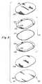
図1〜図3は、軟部組織又は筋肉の欠損修復用植込み型プロテーゼの実施形態を示す。プロテーゼ20は、組織浸潤性材料の内殖層22を備える。内殖層22は、組織又は筋肉の癒着を許容する、又はその他の形でそれを起こし易い少なくとも1つの材料層を備える。一実施形態において、内殖層は、一体に接合された第1の層22aと第2の層22bとを備える。各層22a、22bは、植え込み後にプロテーゼを宿主組織又は筋肉に固定するのに十分な組織又は筋肉の内殖を可能にする複数の間隙又は開口を備えた、生物学的に適合性を有する可撓性材料で形成される。 1-3 show an embodiment of an implantable prosthesis for soft tissue or muscle defect repair.
一実施形態において、各層22a、22bは、C.R. Bard, Inc.から入手可能なBARD MESHなどの編上ポリプロピレンモノフィラメントメッシュ布材で形成される。ポリプロピレンメッシュは、植え込まれると、メッシュ構造の内部及び周囲への組織又は筋肉の速やかな内殖を促進する。或いは、SOFT TISSUE PATCH(微孔性ePTFE−W.L. Gore & Associates, Inc.から入手可能);SURGIPRO(US Surgical, Inc.から入手可能);TRELEX(Meadox Medicalから入手可能);PROLENE及びMERSILENE(Ethicon, Inc.から入手可能);及び他のメッシュ材料(例えば、Atrium Medical Corporationから入手可能)を含め、組織及び筋肉の補強及び欠損修正に好適な他の材料が利用されてもよい。特定の用途には、ポリグラクチン(VICRYL−Ethicon, Inc.から入手可能)及びポリグリコール酸(DEXON−US Surgical, Inc.から入手可能)を含む吸収性材料が好適であり得る。C.R. Bard, Inc.からのCOLLAMEND又はCook Biomedical, Inc.から入手可能なSURGISISなどのコラーゲン材料もまた、用いられ得る。また、メッシュ布材をマルチフィラメント糸から形成してもよく、編上げ、織上げ、編組み、成形などの任意の好適な方法を用いてプロテーゼメッシュ材料を形成し得ることも企図される。 In one embodiment, each
適切な組織又は筋肉の内殖を確実に生じさせるため、2つの材料層は、各層22a、22bの間隙又は孔隙内への組織成長を可能にし、周囲の筋肉又は組織と層22bとの間の強固な結合をもたらし得るような方法で取り付けられ得る。一実施形態において、第1の層22aと第2の層22bとは、ステッチ30で連結される。 To ensure proper tissue or muscle ingrowth, the two material layers allow tissue growth into the gaps or pores of each
一実施形態において、第1の層22aと第2の層22bとは、離散的な位置においてのみ取り付けられる。このようにすることで、組織又は筋肉が第1の層22aを通じて第2の層22bの中まで成長することができる。単一のステッチライン30であっても、内殖層を互いに固定するには十分であり得るが、内殖層22a及び22bが波打つ程度を抑えるため、追加的なステッチラインを用いることが望ましいこともある。加えて、取付け部は同心状のパターンを含むように図示されるが、層の分離を最小限に抑えるための任意の好適なパターンが用いられ得る。 In one embodiment, the first layer 22a and the
第1の層と第2の層とは、他の好適な技法を用いて取り付けてもよいため、本発明はいかなる特定の取付け方法にも限定されないことは理解されなければならない。例えば、これらの層は、層を特定の位置で、若しくは特定のパターンに溶融するか;層を音波、誘導、振動、若しくは赤外線/レーザー溶接するか;又は好適な結合剤を使用することによって一体に結合されてもよい。1つ又は複数の取付け箇所は、ドット又はビーズの渦巻きパターン、蛇行パターン又は格子状パターンなど、組織又は筋肉が浸潤するのに十分な量の開いた、すなわち充満していない間隙を維持する任意の好適なパターンを含み得る。 It should be understood that the present invention is not limited to any particular method of attachment, as the first and second layers may be attached using other suitable techniques. For example, the layers can be fused by melting the layers at specific locations or in specific patterns; sonic, induction, vibration, or infrared / laser welding the layers; or by using a suitable binder. May be combined. One or more attachment points can be any one that maintains a sufficient amount of open or unfilled gaps for tissue or muscle infiltration, such as a swirl pattern, serpentine pattern, or grid pattern of dots or beads. Any suitable pattern may be included.
プロテーゼの位置決め及び/又は一時的な取付けを補助するため、プロテーゼは少なくとも1つのポケット32を備えてもよい。このようにすることで、外科医がポケットを用いてプロテーゼを所望の範囲に位置決めし得る。その後、外科医は材料層の一方を、周囲の内殖組織、筋肉又は腹膜層に縫合又はステープル留めし得る。例えば、外科医はポケットに入り、ポケットの上側の層を組織、筋肉又は腹膜層に縫合又はステープル留めしてもよい。それにより、少なくとも十分な組織又は筋肉の内殖が起こるまで、プロテーゼが一時的に所定位置に保たれ得る。一実施形態において、第1の層22aと第2の層22bとは、それらの間にポケット32を形成するように取り付けられる。しかしながら、本発明はこれに関して限定されず、ポケット32は用いられなくともよく、又は他の好適な方法で形成された他の好適なポケットが用いられてもよいことは理解されなければならない。例えば、ポケットは、第1の層22aに取り付けられた追加的な材料層又はその一部分から形成されてもよい。 The prosthesis may include at least one
ポケットの内側へのアクセスを得るため、プロテーゼは、ポケット32に至る少なくとも1つの開口を備え得る。一実施形態において、この開口は、第1の層22aに形成された細長いカット又はスリット34を含む。しかしながら、プロテーゼは、当業者に明らかであろうとおりの、ポケットへのアクセスを可能にする任意の好適な開口を備え得ることは理解されるべきである。 To gain access to the inside of the pocket, the prosthesis may comprise at least one opening leading to the
プロテーゼを位置決めするため、外科医は1本又は複数の指(又は好適な手術器具)をポケット内に挿入し、プロテーゼを所定位置に操作し得る。一実施形態において、ポケット32は外科医の手の数本の指が入るサイズとされるが、しかしながら本発明がこれに関して限定されることはないため、他の好適にサイズが決められたポケットが用いられてもよい。さらに、ポケット32は、1本又は複数の指を個々の指用セクションに挿入し得るような複数の開口を有する複数のポケットから形成されてもよい。 To position the prosthesis, the surgeon may insert one or more fingers (or suitable surgical instruments) into the pocket and manipulate the prosthesis into place. In one embodiment, the
腹壁ヘルニアの修復又は胸壁若しくは腹壁の再建などの特定の手技においては、内殖層が、内殖層の中への成長が意図されない組織、筋肉又は臓器と接触し得る。かかる接触は、潜在的に内殖層と周囲の組織、筋肉又は臓器との間の望ましくない術後癒着を引き起こす可能性がある。プロテーゼの特定の部分に対する術後癒着の発生を最小限に抑え、又はそれをなくすため、プロテーゼは、内殖層22の一方の側面の少なくとも一部分、好ましくは全面の上に重なる組織、筋肉又は臓器癒着抵抗性バリア層36を備え得る。 In certain procedures, such as repairing an abdominal wall hernia or reconstruction of the chest wall or abdominal wall, the ingrowth layer may come into contact with tissues, muscles or organs that are not intended to grow into the ingrowth layer. Such contact can potentially cause unwanted post-operative adhesions between the ingrowth layer and surrounding tissues, muscles or organs. In order to minimize or eliminate the occurrence of post-surgical adhesions to certain parts of the prosthesis, the prosthesis is a tissue, muscle or organ that overlies at least a portion, preferably the entire surface, of one side of the ingrowth layer An adhesion
一実施形態において、バリア層36は、プロテーゼに対して第2の層22bに隣接した側面で取り付けられる。プロテーゼ20は、患者体内において、腹部内臓(例えば、腸)又は胸部内臓(例えば、心臓又は肺)などの、望ましくない癒着を起こし得る領域に対してバリア層36が向かい合うように位置決めされ得る。以下でさらに詳細に考察するとおり、バリア層36の形成は、植え込まれたときに組織、筋肉又は臓器の内殖及び癒着形成を実質的に刺激せず、事実上それに抵抗し、従って内殖層と隣接する組織、筋肉又は臓器との間の望ましくない術後癒着の発生を抑制し、又は完全になくす材料で、及び/又はそのような構造によって行われる。 In one embodiment, the
一実施形態において、バリア層36は、著しい組織内殖を許容しないフィブリル長さ−孔径又はノード間距離とも称される−を有する延伸ポリテトラフルオロエチレン(ePTFE)のシートから形成される。一実施形態において、ePTFEのフィブリル長さは5μm未満である。別の実施形態において、ePTFEのフィブリル長さは1μm未満であり、さらに別の実施形態においてフィブリル長さは0.5μm未満である。バリア層36の形成に好適な他の材料の例としては、C.R. Bardから入手可能なFLUORO-TEX心膜及び腹膜サージカルメンブレン(Pericardial and Peritoneum Surgical Membrane)及びFLUORO-TEX硬膜代用膜(Dura Substitute)並びにW. L. Gore & Associates, Inc.から入手可能なPRECLUDE心膜メンブレン(Pericardial Membrane)、PRECLUDE腹膜メンブレン(Peritoneal Membrane)及びPRECLUDE硬膜代用メンブレン(Dura Substitute membrane)が挙げられる。 In one embodiment,
他の好適な微孔性ないし無孔性材料の代表的且つ非限定的な実例としては、Dow Corning Corporationによって流通するSILASTIC Rx医療級シート材(Medical Grade Sheeting)(白金硬化)などのシリコーンエラストマー、並びに微孔性ポリプロピレンシート材(Celgard, Inc.から入手可能)及びフィルムが挙げられる。例えば、心膜及び小腸粘膜下組織を含め、自家組織、他家組織及び異種組織もまた企図される。用途によっては、Genzyme Corporationから入手可能なSEPRAFILMなどの吸収性材料及び酸化再生セルロース(Intercede (TC7))が用いられてもよい。他の好適な生体適合性の耐癒着性材料もまた用いられ得ることは理解されるべきである。 Representative and non-limiting examples of other suitable microporous or nonporous materials include silicone elastomers such as SILASTIC Rx Medical Grade Sheeting (platinum cured) distributed by Dow Corning Corporation, And microporous polypropylene sheet materials (available from Celgard, Inc.) and films. For example, autologous, allogeneic and xenogeneic tissues are also contemplated, including pericardium and small intestine submucosa. Depending on the application, absorbent materials such as SEPRAFILM available from Genzyme Corporation and oxidized regenerated cellulose (Intercede (TC7)) may be used. It should be understood that other suitable biocompatible adhesion resistant materials may also be used.
プロテーゼ20は、従来の組織を相接させる方法が実現不可能な場合の組織欠損の修復、例えば、大型の瘢痕ヘルニアなどの大型欠損、特に、過去の手術によって弱まった組織若しくは筋肉又は肥満患者の組織若しくは筋肉に生じる大型欠損の修復に特に有用であり得る。そのため、プロテーゼ20は、組織又は筋肉が内殖層の中へと成長するに従い、及びかかる内殖が生じた後に、欠損を架橋して周囲の組織又は筋肉を支持する。一実施形態では、患者によって(例えば、患者の動作によって)引き起こされる応力を支持し、それにより欠損再発を抑制するため、組織又は筋肉が、かかる応力の支持に最も適した内殖材料層の中へと成長できることが望ましい。第1の層22aは少なくとも1つの開口34を備えるため、要求される応力を支持する能力は比較的低い。他方で、第2の層22bは大寸法の開口、又は他の大きい不連続部分は含まず、概して均一であり、従って要求される荷重を支持する能力がより高い。従って、本明細書に記載される実施形態では、耐力層は第2の層22bである。 The
本発明はこれに関して限定されず、プロテーゼ20は、好適にサイズ及び形状が決められた開口又は不連続部分を第2の層22bに有して形成されてもよい(かかる開口又は不連続部分が許容量を超えて第2の層の耐荷力を低減しないことを条件として)ことは理解されなければならない。例えば、比較的小さいプロテーゼには、かかる開口又は不連続部分が用いられ得る。これらの開口又は不連続部分を用いると、プロテーゼを少なくとも一時的に固定し、組織内殖を促進するのに役立ち得る。かかる開口及び不連続部分を用いるプロテーゼの例が、本発明の譲受人に譲渡され、及び本明細書によって全体として参照により援用される米国特許第6,290,708号及び同第6,224,616号に記載されている。 The present invention is not limited in this regard, and the
第2の層22bの中への組織又は筋肉の成長を可能にし、且つ促進するため、バリア層36は好ましくは、組織が第2の層22bの孔隙の中へと成長することができ、周囲の筋肉又は組織と第2の層22bとの間に強固な結合をもたらすような方法で、第2の層22bに取り付けられ得る。 In order to allow and promote tissue or muscle growth into the
一実施形態において、第1の層22aと第2の層22bとは、内殖層、特に第2の層22bに対する十分な組織浸潤を可能にすると同時に第1の層22aと第2の層22bとの連結を提供するステッチを用いて、離散的な取付けラインによって互いに取り付けられる。加えて、これらの同じステッチ(例えば、ステッチ38)が、第2の層22bをバリア層36に固定するためにも用いられ得る。ステッチライン38はバリア層36を内殖層22に十分に固定し得るが、中心ステッチライン39のように、バリア層が波打って内殖層から離れる程度を抑えるための追加的なステッチラインを使用することが望ましいこともある。取付け部は同心状のパターンを含むように示されるが、内殖層とバリア層との分離を最小限に抑えるための任意の好適なパターンが用いられ得る。 In one embodiment, the first layer 22a and the
必要であれば、第1の層22aと第2の層22bとを互いに固定するために、第2の層22bをバリア層36に固定するために用いられるステッチと比較して異なるステッチ群を用いてもよい。例えば、全てのステッチライン30がバリア層36を通過する必要はない。むしろ、バリア層36を通過するのはステッチライン38のみである。バリア層36の第2の層22bとの固定には、プロテーゼのバリア層側に対する組織又は筋肉の癒着を最小限に抑えるため、必要最小限のステッチのみが用いられることが好ましい。また、示される実施形態において、中心ステッチライン39は、第1の層22aがその位置にアクセス開口32を備えることから、第2の層22b及びバリア層36のみを通過する。 If necessary, use different stitch groups compared to the stitches used to secure the
一実施形態において、バリア層36はステッチによって内殖層22bに取り付けられるが、バリア層は他の好適な技法を用いて取り付けられてもよいため、本発明はこれに関して限定されないことは理解されなければならない。例えば、バリア層は、層を加熱するか、層を溶接するか、又は好適な結合剤を使用することによって内殖層と結合されてもよい。いずれの場合にも、組織又は筋肉が浸潤するのに十分な量の開いた、すなわち充満していない間隙が少なくとも第2の層22bに維持されることを条件として、ドット又はビーズの渦巻きパターン、蛇行パターン又は格子状パターンなどの好適なパターンが用いられ得る。 In one embodiment, the
内殖層22bをバリア層36に取り付けるためにステッチが用いられる場合、癒着をさらに最小限に抑えるため、ステッチは無孔性の耐癒着性材料から形成され得る。例えば、ステッチは、好適なポリテトラフルオロエチレン(PTFE)モノフィラメントによって形成されてもよい。PTFEステッチは、ポリプロピレンモノフィラメントなどの他のステッチ材料を使用したプロテーゼと比較して操作が容易な、より軟質でより可撓性の高いプロテーゼを提供し得る。PTFEモノフィラメントはまた、その材料の低摩擦特性に起因して、製造プロセスも容易となる。それにもかかわらず、ステッチには、ポリプロピレンモノフィラメントなどの任意の好適な材料を用い得ることは理解されなければならない。例えば、ステッチラインの一部はバリア層を通過しないため、又はバリア層が用いられない場合、耐癒着性材料以外の材料が用いられてもよい。しかしながら、製造の容易さから、全てのステッチは同じ材料で形成することができ、但し本発明がこれに関して限定されることはない。 If stitches are used to attach the
層は、ボビンと縫糸とを使用するミシンによって形成される典型的な縫製用ステッチを用いて縫い付けられ得る。好ましくは、各ステッチ(すなわちボビン)の結節点が、プロテーゼのバリア側ではなく、内殖側に形成されることで、組織、筋肉又は臓器との局所的な癒着の発生が低減されるように、バリア層が縫針と向かい合うように内殖層上に位置決めされる。ステッチは、ステッチ穴を通じて内殖が発生する可能性を低減するため、10号ボールポイント針を使用して形成され得る。バリア層を有する、又は有しない内殖材料シートは、縫製作業中、所望のステッチパターンがプログラムされたコンピュータ制御の台上にあるフレームによって保持され得る。 The layers can be sewn using typical sewing stitches formed by a sewing machine using bobbins and sewing threads. Preferably, the knots of each stitch (ie bobbin) are formed on the ingrowth side rather than on the barrier side of the prosthesis so that the occurrence of local adhesions with tissue, muscle or organ is reduced. The barrier layer is positioned on the ingrowth layer so as to face the sewing needle. Stitches can be formed using a No. 10 ball point needle to reduce the likelihood of ingrowth occurring through the stitch holes. The in-growth material sheet with or without a barrier layer can be held by a frame on a computer-controlled table programmed with the desired stitch pattern during the sewing operation.
バリア層36は、好ましくは内殖層22の一方の側面の表面全体を被覆するが、バリア層36は、プロテーゼの一方の側面の特定の部分のみを被覆するように構成されてもよく、それによりバリア層のない部分において双方の側からの内殖を増進し得ることが理解されるべきである。同様に、プロテーゼは、バリア層がプロテーゼの一方の側面で表面全体を被覆し、且つプロテーゼの他方の側面の1つ又は複数の部分を被覆するように構成されてもよい。 The
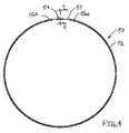
ある場合には、プロテーゼ20の外周縁端を隣接する組織、筋肉又は臓器と隔離することが望ましいこともある。一実施形態において、プロテーゼ20の外周縁端24を囲んで周囲バリア40が全面的に延在し、そこへの癒着を抑制する。しかしながら、周囲バリア40は、プロテーゼの外周縁端のうち、術後癒着の形成からの保護が求められる特定の部分のみを被覆するように構成されてもよいことは理解されるべきである。 In some cases, it may be desirable to isolate the outer peripheral edge of the
周囲バリア40は、内殖層22又はバリア層36のいずれかと一体化して形成されてもよい。或いは、周囲バリア40は、プロテーゼの外周縁端に取り付けられるか、又はそこに組み込まれる別個の構成要素によって形成されてもよい。一例示的実施形態において、周囲バリア40は内殖層22の一部分から形成される。詳細には、内殖層22が、その外縁に沿った組織浸潤可能な間隙又は開口を実質的になくすように改造され、それにより周囲バリア40が設けられ得る。 The surrounding
一実施形態では、層22の周囲縁端24を溶融することにより材料がシールされ、外周バリア40が形成される。バリア層36は、サブミクロンサイズの孔隙を有するなどして、層22の溶融した材料がバリア層36と融合するように構成されてもよい。周囲縁端24は、任意の好適な方法を用いて溶融され得る。一実施形態では、層をヒートシールすることにより周囲縁端24が溶融され得る。例示的実施形態において、周囲バリア40は、ポリプロピレンメッシュ布材の環体を、ePTFEバリア層36に対して所望のプロテーゼ構成に近い形状に溶融することにより形成される。これは、固定具内にオーバーサイズのメッシュ布材シート及びePTFE材料シートを重ねて置き、それらの層を、所望のプロテーゼ形状に構成された加熱ダイを使用して熱融着することにより達成され得る。溶融した環体は、布材に対して熱を約320°F〜400°Fの温度範囲で約3〜5秒間にわたって加えることにより形成され得る。選択される温度は、典型的にはePTFEバリア層の焼結温度未満とすべきである。超音波、誘導、振動、赤外線/レーザー溶接など、他のシール技法が用いられてもよく、本発明はそれに関して限定されるものではない。融合後、上記のとおり内殖層をバリア層に縫い付け、続いて環体の一部分に沿って面一に打抜きすることにより、周囲バリアを有するプロテーゼを完成させる。 In one embodiment, the material is sealed by melting the
周囲バリアの作製については、本発明はそれに関して限定されないため、他の好適な技法が用いられてもよい。かかる他の技法の例が、本発明の譲受人に譲渡され、且つ全体として参照により本明細書に援用される米国特許第7,404,819号に記載されている。 Other suitable techniques may be used for the creation of the surrounding barrier, as the invention is not limited in that regard. Examples of such other techniques are described in US Pat. No. 7,404,819, assigned to the assignee of the present invention and incorporated herein by reference in its entirety.
上記のいくつかの実施形態はバリア層を含むが、これに関して本発明が限定されることはない。従って、他の実施形態はバリア層又は周囲バリアを備えることも、又は備えないこともある。 Some of the above embodiments include a barrier layer, but the invention is not limited in this regard. Thus, other embodiments may or may not include a barrier layer or surrounding barrier.
場合によっては、例えば(限定はされないが)比較的大型の欠損の修正では、所望の範囲において容易且つ効果的に操作及び位置決めし得るのに十分な剛性を有し、さらに、プロテーゼを植え込む医師及びプロテーゼを受け入れる患者の双方がそのプロテーゼを十分に許容し得るための十分な可撓性を有するプロテーゼを用いることが望ましいこともある。プロテーゼは被覆範囲の形状に適合しなければならず、且つ縁端が過剰に丸まることのないように十分な剛性を有しなければならない。この特性は、肥満患者の大型欠損で用いられるサイズの大型のプロテーゼで特に有用となり得る。従って、本発明の一態様によれば、プロテーゼ20は剛性と可撓性との均衡をとるため、支持アセンブリ50を備える。この支持アセンブリは、任意の好適な方法で内殖層に結合され得る。 In some cases, for example (but not limited to), repairing a relatively large defect is sufficiently rigid to be easily and effectively manipulated and positioned within a desired area, and further includes a physician who implants the prosthesis and It may be desirable to use a prosthesis that is sufficiently flexible so that both patients receiving the prosthesis can sufficiently tolerate the prosthesis. The prosthesis must conform to the shape of the coverage area and must be sufficiently rigid so that the edges are not excessively rounded. This property can be particularly useful with large prostheses of the size used in large defects in obese patients. Thus, according to one aspect of the invention, the
支持アセンブリはプロテーゼの安定性に寄与し、それによりプロテーゼは、固定技法が適正であることを前提として、植え込み手技中に所望の形状を保つことが可能となる。この安定性によって取り扱い易くなることで、プロテーゼの展開及び留置が容易となる。例えば、支持アセンブリは、植え込み中にプロテーゼを実質的に平面状に保つことができるように補助する。プロテーゼの植込みにおいて支持アセンブリの周囲に縫合糸を通すことにより、プロテーゼをほぼ所望の構成及び位置に保持し得る。 The support assembly contributes to the stability of the prosthesis, which allows the prosthesis to maintain a desired shape during the implantation procedure, provided that the fixation technique is appropriate. This stability makes it easier to handle and facilitates deployment and placement of the prosthesis. For example, the support assembly helps to keep the prosthesis substantially planar during implantation. By passing the suture around the support assembly during implantation of the prosthesis, the prosthesis can be held in a generally desired configuration and position.
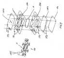
図3に示される一例示的実施形態において、支持アセンブリ50は支持部材又は補剛部材51を備え、この補剛部材はそれを内殖層22と分離する材料によって取り囲まれている。補剛部材は弾性であってもよく、それにより支持アセンブリを拡張した構成から折り畳むか、又は変形させることができるため、プロテーゼを手術部位に送り込むことが容易となり、次にその拡張した構成に戻ることで、手術部位におけるプロテーゼの取扱い及び支持が容易となる。一実施形態において、補剛部材は材料スリーブ52内に位置してもよい。しかしながら、支持アセンブリには、補剛部材51を内殖層22と分離する材料で補剛部材を取り囲む、当業者に明らかな他の好適な構成が用いられ得ることは理解されるべきである。 In one exemplary embodiment shown in FIG. 3, the
一実施形態において、補剛部材51は吸収性材料で形成される。吸収性補剛部材により、プロテーゼの最初の取扱い及び展開が容易となる。その後、補剛部材は徐々に分解され、最終的には体内に完全に吸収される。かかる構成は、それ以上プロテーゼの取扱い及び展開を容易にする必要がなくなった後に、補剛部材が最終的に体内に吸収される点で、有利であり得る。 In one embodiment, the stiffening
一実施形態において、補剛部材51は、直径が約0.038インチのポリジオキソナン(PDO)モノフィラメントから形成される。しかしながら、補剛部材は、好適な剛性及び取扱い特性が維持されるならば、モノフィラメント、マルチフィラメント又は成形形材を含め、任意の生体適合性の吸収性又は非吸収性材料で形成され得ることが企図される。補剛部材(又はまとまって補剛部材を形成する個々のフィラメント若しくはバンド)は、円形、正方形、矩形、三角形、楕円形等の、任意の好適な断面寸法及び形状を有し得ることは理解されなければならない。 In one embodiment, the stiffening
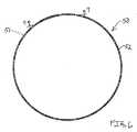
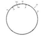
一例示的実施形態において、プロテーゼには、環形状に構成された補剛部材51が用いられる。しかしながら、補剛部材は、渦巻きパターン、正方形パターン、楕円形パターン、円形パターンなど、いかなるパターンで構成されてもよい。図示されるとおりの一実施形態において、支持アセンブリ50には、連続的な途切れのない環体が用いられる。この環体は、所定長さのモノフィラメントなどの材料の端部分を接合することによって形成されてもよい。しかしながら、補剛部材は、1つ又は複数の別個の不連続なセグメントが、プロテーゼに好適な剛性及び取扱い性を付与し得る任意の構成に配置されることによって形成されてもよいことは理解されなければならない。 In one exemplary embodiment, the prosthesis uses a stiffening
スリーブ52は多孔質材料で形成されてもよく、それにより体液及び/又は組織の通過又は浸潤が可能となり、補剛部材51の分解及び/又は吸収が促進される。一実施形態において、材料は、約0.00035in2〜約0.00085in2のサイズの間隙又は孔隙を備える。約0.00085in2の間隙又は孔径のスリーブを用いることは、約0.00085in2の同様の孔隙又は間隙サイズの材料で形成された内殖層22と共に支持アセンブリが用いられる場合に望ましいこともある。0.00085in2超などのより大きい孔隙又は間隙サイズを有する材料で形成された内殖層22と共に支持アセンブリが用いられる場合には、約0.00035in2などのより小さい間隙又は孔径を有するスリーブが望ましいこともある。しかしながら、スリーブには、当業者に明らかであろうとおりの他の好適な間隙又は孔径を有する材料が用いられ得ることは理解されるべきである。The
一実施形態において、スリーブ52は、間隙又は孔隙を備えるメッシュ布材から形成され、それにより組織が支持アセンブリへと浸潤又は内殖し、最終的に補剛部材51を取り囲んで吸収することが可能となる。一実施形態において、スリーブは編上ポリプロピレンメッシュから形成される。このメッシュは、直径が約0.006インチのモノフィラメントを編み上げたものであり得る。メッシュには、所望の特性を提供する任意の好適な布材パターンが用いられ得る。スリーブは、限定はされないが、内殖層に用いられる材料又はその他の好適な特性を有する生体適合性材料を含め、任意の好適なメッシュ材料で形成され得ることが理解されるべきである。また、スリーブはマルチフィラメント糸から形成されてもよく、編上げ、織上げ、編組み、成形などの任意の好適な方法を用いてスリーブを形成し得ることも企図される。 In one embodiment, the
図3に示される一例示的実施形態では、スリーブは、メッシュ52a、52bの2つの環体によって形成されてもよく、それらのメッシュ52a、52bが取り付けられることでスリーブが形成される。各メッシュ環体の幅は約0.25〜0.38インチであってもよい。図示されるとおり、メッシュ環体52a、52bの間に補剛部材51が挟置され、メッシュ環体52a、52bは、材料スリーブ内に補剛部材を取り囲むように、補剛部材の内側及び外側に沿って互いに取り付けられる。 In one exemplary embodiment shown in FIG. 3, the sleeve may be formed by two rings of mesh 52a, 52b, and the mesh is formed by attaching the mesh 52a, 52b. The width of each mesh ring may be about 0.25 to 0.38 inches. As shown, a stiffening
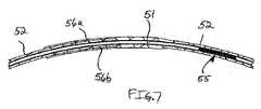
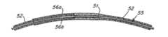
必要であれば、スリーブは、シングルピースの材料で形成された単一部材として構成されてもよい。図4〜図7に示される一例示的実施形態において、支持アセンブリ50には、補剛部材51を中に受け入れるチューブ状又はソックス状部材として構成されたスリーブ52が用いられ得る。一実施形態において、このスリーブは、チューブ状メッシュ布材材料である。 If desired, the sleeve may be configured as a single piece formed of a single piece of material. In one exemplary embodiment shown in FIGS. 4-7, the
図4に示されるとおり、所定長さの補剛部材51用材料がスリーブ52中に挿通され、材料の端部が互いに接合されて輪をなすことにより、連続的な環状構成を形成する。図5に示されるとおり、補剛部材51の端部分54は重ねて置かれ、溶接、接着などの任意の好適な技法を用いて接合部55で一体に接合され得る。補剛部材の端部54を接合した後、スリーブ材料の端部56a、56bが互いに補剛部材51を覆って完全に引き上げられ、接合されて、補剛部材を覆う連続的なスリーブを形成する。図6〜図7に示されるとおり、スリーブ52の端部56a、56bは、補剛部材を完全に被覆するように重なり合ってもよい。スリーブ材料の一方の端部56aがフレア状に拡がっていてもよく、それによりスリーブの反対側の端部56bに被さって嵌まることで、補剛部材の完全な被覆を確実にし、且つスリーブ端部の接合を容易にする。 As shown in FIG. 4, a predetermined length of the stiffening
支持アセンブリについていくつかの例示的実施形態が提供されているが、支持アセンブリには、当業者に明らかな他の構造上の構成が用いられ得ることは理解されるべきである。 Although several exemplary embodiments are provided for the support assembly, it should be understood that other structural configurations apparent to those skilled in the art may be used for the support assembly.
支持アセンブリ50は、プロテーゼの外側範囲26を取り囲み、少なくともその外側範囲26を補強するように構成され得る。図中に示される実施形態において、支持アセンブリ50は周囲縁端24には配置されない。むしろ、支持アセンブリ50は周囲縁端24から内側に離間される。しかしながら、支持アセンブリ50は周囲縁端24に配置されてもよいため、本発明はこれに関して限定されないことは理解されなければならない。 The
支持アセンブリ50は、任意の好適な方法でプロテーゼに配置されてもよく、本発明がこれに関して限定されることはない。一実施形態において、支持アセンブリ50は、内殖材料の第1の層22aと第2の層22bとの間に挟置されるとともに、そこに物理的に取り付けられても、又は取り付けられなくともよい。縫糸によって形成されたステッチライン30が、少なくとも支持アセンブリ50の外側縁端53a又は内側縁端53b(図3)に沿って、又はそこを通じて縫い付けられ、それにより支持アセンブリが層22a及び22bに対して動かないようにされてもよい。支持アセンブリ50は剛性を有するため、支持アセンブリ50の一方の側に沿った、又はそこを通じる1本のステッチラインで十分であり得る。しかしながら、好ましくは、2本のステッチラインが、アセンブリの各縁端に一つずつとして支持アセンブリを所定位置に固定する。好ましくは、バリア層36が存在する場合に、これらのステッチは第1の層22a及び第2の層22bの双方を通じて延在するが、バリア層36は通らない。 The
別の利点は、支持アセンブリ50が、バリア層36に、又は第1の層22a及び第2の層22bに縫い付けられるか、又は結合される場合には層22a、22b及び/又は層36を一体に保持し、それにより層36が層22に対して、又は層22a及び22bが互いに対して波打つことが防止されることである。 Another advantage is that when the
或いは、支持アセンブリ50は、内殖層22の上又は下に重ねて置かれてもよく、及び位置にかかわらず、ステッチ若しくは結合剤によって取り付けられるか、又は超音波、誘導、振動、赤外線/レーザー溶接などによって融合されてもよい。バリア層が用いられる場合に、支持アセンブリ50がバリア層36の下に位置決めされたり、又はバリア層36から突出したりすると、結果として支持アセンブリに望ましくない癒着が形成され得るため、そのようにはされないことが望ましいこともある。 Alternatively, the
補剛部材51はモノフィラメントで形成されるものとして記載されるが、他の好適な構造が用いられてもよいことは理解されるべきである。例えば、補剛部材は、プロテーゼに順番に取り付けられるか、又は重ねて成形される1つ又は複数の成形要素であってもよい。 Although the stiffening
図8に示される別の実施形態では、第1の支持アセンブリ50の内側に第2の支持アセンブリ60が配置されてもよく、これは、プロテーゼの内側範囲28を補強するために用いられるものであり得る。図示されるとおり、第2の内側支持アセンブリ60は、第1の外側支持アセンブリ50と同心状か、又は略同心状であってもよい。しかしながら、他の好適な構成が用いられ得るため、本発明はこれに関して限定されないことは理解されなければならない。 In another embodiment shown in FIG. 8, a
一実施形態において、プロテーゼ20は比較的平坦であり、且つ十分に柔軟であるため、外科医がプロテーゼを操作して対象とする解剖学的部位にプロテーゼを挿入し、プロテーゼの形状を適合させることが可能であり、プロテーゼの縫合、ステープル留め、又はその他の方法による固定が可能である。プロテーゼ20は、特定の欠損の修正を容易にする助けとなる任意の好適な形状又はサイズを有するように構成され得る。図中に示される実施形態において、プロテーゼ20は、略平坦な楕円形状を有する。他の形状の例としては、限定はされないが、円形、正方形、矩形及び不規則な形状が挙げられる。 In one embodiment, the
例示的実施形態において、第1の層22a及び第2の層22bの各々は、直径約0.006インチのポリプロピレンモノフィラメントから編み上げられたBARD MESHの約0.027インチ厚シートで形成される。バリア層36は、ePTFEの約0.006〜0.008インチ厚シートから形成される。バリア36は、0.008インチ〜0.012インチ直径のPTFEモノフィラメントで形成される約3mm〜4mm長さのステッチを用いて層22a及び22bに取り付けられる。 In the exemplary embodiment, each of the first layer 22a and the
一実施形態において、プロテーゼ20は、任意の所望のサイズを有し得る略楕円形状を有する。例えば、プロテーゼは、概して楕円の長軸及び短軸に沿って計測したとき、ほぼ以下のとおりのサイズを有し得る:5インチ×7インチ;7インチ×9インチ;8インチ×10インチ;又は10インチ×13インチ。プロテーゼはまた、50平方cmより大きい面積を被覆するようなサイズであってもよい。一実施形態において、プロテーゼは、約68平方cm;別の実施形態において、約119平方cm;さらに別の実施形態において、約152平方cm;なお別の実施形態において(例えば、肥満患者用)約246平方cmの面積を被覆する。しかしながら、記載される材料及び寸法は単に例示に過ぎず、プロテーゼには任意の好適なサイズ及び形状が用いられ得ることは理解されなければならない。 In one embodiment, the
一実施形態において、プロテーゼは、プロテーゼが欠損の縁端に少なくとも3cm、いくつかの実施形態においては少なくとも4cm、さらに他の実施形態においては少なくとも5cmだけ重なるようなサイズとされる。プロテーゼは上記で単一の欠損を修正するものとして記載されているが、好適なサイズ及び形状のプロテーゼを使用して2つ以上の欠損を修正し得ることが企図される。 In one embodiment, the prosthesis is sized such that the prosthesis overlaps at the edge of the defect by at least 3 cm, in some embodiments at least 4 cm, and in other embodiments by at least 5 cm. Although a prosthesis has been described above as correcting a single defect, it is contemplated that a suitable size and shape prosthesis may be used to correct more than one defect.
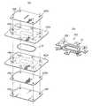
ここで、プロテーゼの製造手順の一例を記載する。補剛部材51を打抜き材料の2つの環体52a、52bの間に捕捉することにより、支持アセンブリ50が作製される。図9は、プロテーゼ20を形成するために使用される材料ブランクの分解図を示す。支持アセンブリ50を形成するため、メッシュ層152bがマルチピン位置合わせ固定具上に平坦に、位置合わせピンが各ブランクに提供された位置合わせ穴156を挿通するように位置決めされる。次に、メッシュ層152b上に補剛部材51が位置決めされる。その後、メッシュ層152aが、固定具の位置合わせピンが対応する位置合わせ穴を挿通するようにして、補剛部材51の上に重ねて置かれる。次に、補剛部材51の各側にステッチ列を設けることによりメッシュ層152a、152bが互いに取り付けられ、それらの間に補剛部材が捕捉される。 Here, an example of the prosthesis manufacturing procedure will be described. The
次に、補剛部材が捕捉されている組み立て済みの層を打抜きすると、支持アセンブリ152が得られる。図示されるとおり、結果として得られるアセンブリ152は、半径方向に延在する一連の位置合わせタブ155を備える。 Next, the assembled layer in which the stiffening member is captured is punched to obtain the
位置合わせタブ155を使用して、第1の層122aと第2の層122bとの間に支持アセンブリ152が位置決めされる。第2の層122bに隣接して支持アセンブリ152の反対側にバリア層136が位置決めされる。図1〜図2に示されるステッチパターンを用いてアセンブリが一体に縫い付けられる。次に半径方向タブ155が取り除かれてもよく、アセンブリを加熱ダイに入れて、第1の層122a及び第2の層122bの一部分をバリア層136と融合させてもよい。次に最終的な打抜きを行うことでプロテーゼ20の所望の形状が実現され、結果として得られる周囲縁端は、融合した層によって形成される。 The
プロテーゼの例示的な製造手順は、複数の材料層で形成される支持アセンブリ50の使用と関連して記載されている。当業者であれば理解するであろうとおり、図4〜図7に関連して上記に記載したとおりのチューブ状スリーブを備える支持アセンブリを使用するプロテーゼが、そのチューブ状スリーブ支持アセンブリを第1の材料層122aと第2の材料層122bとの間に位置決めすることにより、同様の方法で製造され得る。 An exemplary manufacturing procedure for a prosthesis is described in connection with the use of a
本発明の様々な実施形態の前述の説明は、単にその例示を目的としているに過ぎず、本発明の他の実施形態、改良例、及び均等物が、ここに添付される特許請求の範囲に記載された本発明の範囲内にあることは理解されなければならない。さらに、上記のプロテーゼは、単独で、又は任意の好適な組み合わせで用いられ得る様々な特徴を含む。 The foregoing descriptions of various embodiments of the present invention are intended for purposes of illustration only, and other embodiments, modifications, and equivalents of the present invention are within the scope of the claims appended hereto. It should be understood that it is within the scope of the described invention. Furthermore, the prosthesis described above includes various features that can be used alone or in any suitable combination.
次に、補剛部材が捕捉されている組み立て済みの層を打抜きすると、支持アセンブリ152(図9(b)に図示)が得られる。図示されるとおり、結果として得られるアセンブリ152は、半径方向に延在する一連の位置合わせタブ155を備える。
Next, the assembled layer in which the stiffening member is captured is punched to obtain the support assembly 152(shown in FIG. 9B) . As shown, the resulting
Claims (33)
Translated fromJapanese前記材料層に取り付けられた支持アセンブリであって、補剛部材と、前記補剛部材を取り囲む材料スリーブとを備える支持アセンブリと、
を含む、植込み型プロテーゼ。A first material layer;
A support assembly attached to the material layer, the support assembly comprising a stiffening member and a material sleeve surrounding the stiffening member;
Implantable prosthesis including.
をさらに含む、請求項1に記載の植込み型メッシュ。A second material layer, attached to the first material layer, forming at least one pocket therebetween,
The implantable mesh according to claim 1, further comprising:
前記第1のメッシュ層に対し、それとの間に少なくとも1つのポケットを有して取り付けられる第2のメッシュ層と、
補剛部材であって、それと前記第1のメッシュ層及び前記第2のメッシュ層との間に位置する材料によって取り囲まれた補剛部材を備える、前記第1のメッシュ層と前記第2のメッシュ層との間に位置する支持アセンブリと、
を含む、植込み型プロテーゼ。A first mesh layer;
A second mesh layer attached to the first mesh layer with at least one pocket therebetween;
A stiffening member comprising the stiffening member surrounded by a material located between it and the first mesh layer and the second mesh layer, the first mesh layer and the second mesh A support assembly positioned between the layers;
Implantable prosthesis including.
前記第1のメッシュ布材層に対し、それとの間に少なくとも1つのポケットを有して取り付けられた第2のメッシュ布材層と、
前記第1のメッシュ布材層と前記第2のメッシュ布材層との間に位置する支持アセンブリであって、メッシュ布材のスリーブに取り囲まれた吸収性補剛部材を備える支持アセンブリと、
それに対する癒着の形成を抑制するバリア層であって、前記第1の層、前記第2の層及び前記支持アセンブリのうちの少なくとも1つに取り付けられるバリア層と、
を含む、植込み型プロテーゼ。A first mesh fabric layer;
A second mesh fabric layer attached to the first mesh fabric layer with at least one pocket therebetween;
A support assembly positioned between the first mesh fabric layer and the second mesh fabric layer, the support assembly comprising an absorbent stiffening member surrounded by a sleeve of mesh fabric;
A barrier layer that inhibits adhesion formation thereto, the barrier layer being attached to at least one of the first layer, the second layer, and the support assembly;
Implantable prosthesis including.
Applications Claiming Priority (3)
| Application Number | Priority Date | Filing Date | Title |
|---|---|---|---|
| US10275908P | 2008-10-03 | 2008-10-03 | |
| US61/102,759 | 2008-10-03 | ||
| PCT/US2009/005424WO2010039249A1 (en) | 2008-10-03 | 2009-10-02 | Implantable prosthesis |
Publications (1)
| Publication Number | Publication Date |
|---|---|
| JP2012504457Atrue JP2012504457A (en) | 2012-02-23 |
Family
ID=42073779
Family Applications (1)
| Application Number | Title | Priority Date | Filing Date |
|---|---|---|---|
| JP2011530052APendingJP2012504457A (en) | 2008-10-03 | 2009-10-02 | Implantable prosthesis |
Country Status (6)
| Country | Link |
|---|---|
| US (1) | US9072586B2 (en) |
| EP (1) | EP2344049B1 (en) |
| JP (1) | JP2012504457A (en) |
| CA (2) | CA2966657C (en) |
| ES (1) | ES2859624T3 (en) |
| WO (1) | WO2010039249A1 (en) |
Cited By (2)
| Publication number | Priority date | Publication date | Assignee | Title |
|---|---|---|---|---|
| KR20150130498A (en)* | 2013-03-15 | 2015-11-23 | 에디컨인코포레이티드 | Single plane tissue repair patch having a locating structure |
| JP2017506956A (en)* | 2014-03-06 | 2017-03-16 | シー・アール・バード・インコーポレーテッドC R Bard Incorporated | Hernia repair patch |
Families Citing this family (22)
| Publication number | Priority date | Publication date | Assignee | Title |
|---|---|---|---|---|
| US20090192530A1 (en) | 2008-01-29 | 2009-07-30 | Insightra Medical, Inc. | Fortified mesh for tissue repair |
| US9439746B2 (en) | 2007-12-13 | 2016-09-13 | Insightra Medical, Inc. | Methods and apparatus for treating ventral wall hernia |
| US8940017B2 (en) | 2008-07-31 | 2015-01-27 | Insightra Medical, Inc. | Implant for hernia repair |
| WO2010096824A1 (en)* | 2009-02-23 | 2010-08-26 | Bartee Barry K | Reinforced ptfe medical barrier |
| CA2849821C (en) | 2011-09-30 | 2020-03-24 | Covidien Lp | Implantable prosthesis for repairing or reinforcing an anatomical defect |
| WO2013122700A1 (en) | 2012-02-13 | 2013-08-22 | Insightra Medical, Inc. | Implant for hernia repair |
| ES2878116T3 (en) | 2012-03-22 | 2021-11-18 | Bard Inc C R | Implantable prosthesis to repair soft tissue |
| US9820837B2 (en)* | 2012-04-10 | 2017-11-21 | Ethicon, Inc. | Single plane tissue repair patch |
| AU2013322268B2 (en)* | 2012-09-28 | 2017-08-31 | Sofradim Production | Packaging for a hernia repair device |
| FR3006581B1 (en) | 2013-06-07 | 2016-07-22 | Sofradim Production | PROSTHESIS BASED ON TEXTILE FOR LAPAROSCOPIC PATHWAY |
| US10245135B2 (en) | 2013-07-08 | 2019-04-02 | Bg Medical, Llc | Segmented skirted surgical mesh |
| USD772410S1 (en) | 2013-08-05 | 2016-11-22 | Bg Medical, Llc | Hernia mesh |
| USD734458S1 (en) | 2013-08-05 | 2015-07-14 | Bg Medical, Llc | Hernia mesh |
| US20170189159A1 (en) | 2014-06-24 | 2017-07-06 | Osteogenics Biomedical, Inc. | Perforated membrane for guided bone and tissue regeneration |
| US10172700B2 (en) | 2014-12-01 | 2019-01-08 | C.R. Bard, Inc. | Prosthesis for repairing a hernia defect |
| EP3236883B1 (en) | 2014-12-24 | 2022-05-04 | C. R. Bard, Inc. | Implantable prosthesis for soft tissue repair |
| US9713520B2 (en)* | 2015-06-29 | 2017-07-25 | Ethicon, Inc. | Skirted tissue repair implant having position indication feature |
| ES2961200T3 (en) | 2015-12-28 | 2024-03-08 | Bard Inc C R | Prosthesis to repair a hernia defect |
| US20220338910A1 (en)* | 2019-09-25 | 2022-10-27 | Cannuflow, Inc. | Method and devices for implantation of biologic constructs |
| US11896472B2 (en) | 2019-10-28 | 2024-02-13 | Grant Technologies Llc | Surgical mesh having ingrowth-preventing coating on one side thereof, and method for making the same |
| CN115361991A (en) | 2020-01-30 | 2022-11-18 | 兰巴姆医疗技术有限公司 | Catheter prosthesis |
| US12004937B1 (en) | 2023-01-13 | 2024-06-11 | Sheridan Technologies Llc | Blunt dissector, delivery and deployment device for delivery and deployment of surgical mesh during soft tissue repairs |
Citations (2)
| Publication number | Priority date | Publication date | Assignee | Title |
|---|---|---|---|---|
| JP2001506906A (en)* | 1996-12-20 | 2001-05-29 | ゴア エンタープライズ ホールディングス,インコーポレイティド | Self-expanding defect closure device and method of making and using same |
| JP2005514156A (en)* | 2002-01-07 | 2005-05-19 | シー・アール・バード・インコーポレーテッド | Implantable prosthesis |
Family Cites Families (241)
| Publication number | Priority date | Publication date | Assignee | Title |
|---|---|---|---|---|
| US3124136A (en) | 1964-03-10 | Method of repairing body tissue | ||
| US2621145A (en) | 1949-08-17 | 1952-12-09 | Machteld E Sano | Bone mat compositions |
| US2671444A (en) | 1951-12-08 | 1954-03-09 | Jr Benjamin F Pease | Nonmetallic mesh surgical insert for hernia repair |
| US3054406A (en) | 1958-10-17 | 1962-09-18 | Phillips Petroleum Co | Surgical mesh |
| US3272204A (en) | 1965-09-22 | 1966-09-13 | Ethicon Inc | Absorbable collagen prosthetic implant with non-absorbable reinforcing strands |
| US3625209A (en) | 1969-06-26 | 1971-12-07 | Medical Supply Co | Bandage with compress pad |
| CA962021A (en) | 1970-05-21 | 1975-02-04 | Robert W. Gore | Porous products and process therefor |
| IT964474B (en) | 1971-07-09 | 1974-01-21 | Cutter Lab | PROSTHETIC SUPPORT FOR PARTS OF THE HUMAN BODY SLIDING BETWEEN THEM |
| US3810467A (en) | 1972-08-31 | 1974-05-14 | Dow Corning | Device for hernia correction |
| US3874388A (en) | 1973-02-12 | 1975-04-01 | Ochsner Med Found Alton | Shunt defect closure system |
| US4000348A (en) | 1974-10-15 | 1976-12-28 | Carlisle Corporation | Flat multiconductor cable and process for manufacture thereof |
| US3965703A (en) | 1975-04-18 | 1976-06-29 | Southern Webbing Mills | Warp knitted compression bandage fabric |
| US4007743A (en) | 1975-10-20 | 1977-02-15 | American Hospital Supply Corporation | Opening mechanism for umbrella-like intravascular shunt defect closure device |
| US4051848A (en) | 1976-03-01 | 1977-10-04 | Levine Norman S | Synthetic skin wound dressing |
| US4031569A (en) | 1976-03-15 | 1977-06-28 | Jacob H John | Nasal septum plug |
| US4147824A (en) | 1976-03-31 | 1979-04-03 | Burkert Gmbh | Multilayer seals and method for their production and joining to seal carriers |
| JPS603842B2 (en) | 1976-09-03 | 1985-01-31 | 住友電気工業株式会社 | Asymmetric pore diameter thin film material and its manufacturing method |
| SU782814A1 (en) | 1977-01-18 | 1980-11-30 | За витель | Prosthesis for closing defect in heart tissues |
| SU676285A1 (en) | 1978-02-08 | 1979-07-30 | Челябинский государственный медицинский институт | Prosthesis for closing ventricular septal defect |
| US4725279A (en) | 1979-01-22 | 1988-02-16 | Sterling Drug Inc. | Bio compatible and blood compatible materials and methods |
| US6080472A (en) | 1979-11-27 | 2000-06-27 | Yeu Ming Tai Chemical Ind. Co., Ltd. | Porous polytetrafluoroethylene molded article |
| US4344999A (en) | 1980-04-22 | 1982-08-17 | W. L. Gore & Associates, Inc. | Breathable laminate |
| US4347847A (en) | 1980-06-06 | 1982-09-07 | Usher Francis C | Method of hernia repair |
| US4452245A (en) | 1980-06-06 | 1984-06-05 | Usher Francis C | Surgical mesh and method |
| US4576608A (en) | 1980-11-06 | 1986-03-18 | Homsy Charles A | Porous body-implantable polytetrafluoroethylene |
| US4385093A (en) | 1980-11-06 | 1983-05-24 | W. L. Gore & Associates, Inc. | Multi-component, highly porous, high strength PTFE article and method for manufacturing same |
| US4478665A (en) | 1980-11-06 | 1984-10-23 | W. L. Gore & Associates, Inc. | Method for manufacturing highly porous, high strength PTFE articles |
| US4713075A (en) | 1981-06-10 | 1987-12-15 | Kurland Kenneth Z | Method for the repair of connective tissue |
| US4400833A (en) | 1981-06-10 | 1983-08-30 | Kurland Kenneth Z | Means and method of implanting bioprosthetics |
| US4585458A (en) | 1981-06-10 | 1986-04-29 | Kurland Kenneth Z | Means and method of implanting bioprosthetics |
| US4403604A (en) | 1982-05-13 | 1983-09-13 | Wilkinson Lawrence H | Gastric pouch |
| US4482516A (en) | 1982-09-10 | 1984-11-13 | W. L. Gore & Associates, Inc. | Process for producing a high strength porous polytetrafluoroethylene product having a coarse microstructure |
| US4598011A (en) | 1982-09-10 | 1986-07-01 | Bowman Jeffery B | High strength porous polytetrafluoroethylene product having a coarse microstructure |
| JPS59109534A (en) | 1982-12-14 | 1984-06-25 | Nitto Electric Ind Co Ltd | Polytetrafluoroethylene porous material |
| JPS59160506A (en) | 1983-02-28 | 1984-09-11 | Kuraray Co Ltd | Composite hollow yarn separating membrane and its production |
| US4561434A (en) | 1983-09-06 | 1985-12-31 | Standard Textile Co., Inc. | Launderable cloth-like product for surgical use and method of making the same |
| DE3412846A1 (en) | 1984-04-05 | 1985-10-17 | Hoechst Ag, 6230 Frankfurt | AREA SHAPED SANDWICH MOLDED BODY |
| US4633873A (en) | 1984-04-26 | 1987-01-06 | American Cyanamid Company | Surgical repair mesh |
| US5032445A (en) | 1984-07-06 | 1991-07-16 | W. L. Gore & Associates | Methods and articles for treating periodontal disease and bone defects |
| FR2577807B1 (en) | 1985-02-22 | 1993-12-03 | Ethnor | ABSORBABLE COMPOSITE SURGICAL MATERIAL, PREPARATION METHOD, RESORBABLE PROSTHESIS MADE FROM SUCH MATERIAL AND USE OF SUCH A PROSTHESIS |
| US4871365A (en) | 1985-04-25 | 1989-10-03 | American Cyanamid Company | Partially absorbable prosthetic tubular article having an external support |
| US4997440A (en) | 1985-04-25 | 1991-03-05 | American Cyanamid Company | Vascular graft with absorbable and nonabsorbable components |
| US4655221A (en) | 1985-05-06 | 1987-04-07 | American Cyanamid Company | Method of using a surgical repair mesh |
| US5002551A (en) | 1985-08-22 | 1991-03-26 | Johnson & Johnson Medical, Inc. | Method and material for prevention of surgical adhesions |
| US5007916A (en) | 1985-08-22 | 1991-04-16 | Johnson & Johnson Medical, Inc. | Method and material for prevention of surgical adhesions |
| US4923464A (en) | 1985-09-03 | 1990-05-08 | Becton, Dickinson And Company | Percutaneously deliverable intravascular reconstruction prosthesis |
| US4693720A (en) | 1985-09-23 | 1987-09-15 | Katecho, Incorporated | Device for surgically repairing soft tissues and method for making the same |
| US4710192A (en) | 1985-12-30 | 1987-12-01 | Liotta Domingo S | Diaphragm and method for occlusion of the descending thoracic aorta |
| US4792336A (en) | 1986-03-03 | 1988-12-20 | American Cyanamid Company | Flat braided ligament or tendon implant device having texturized yarns |
| JPS62216300A (en) | 1986-03-17 | 1987-09-22 | 株式会社イナックス | Manufacturing method of conductive non-woven resin composite molded plate |
| US4769038A (en) | 1986-03-18 | 1988-09-06 | C. R. Bard, Inc. | Prostheses and techniques and repair of inguinal and femoral hernias |
| GB8613015D0 (en) | 1986-05-29 | 1986-07-02 | Thomas T R | Porous ptfe |
| DE3619197A1 (en) | 1986-06-07 | 1987-12-10 | Ethicon Gmbh | UPHOLSTERY IMPLANT |
| FR2604085B1 (en) | 1986-09-19 | 1989-11-17 | Audion Michel | OSTEOSYNTHESIS PLATE FOR CONTAINING AND REDUCING COLLAPSE OF ORBITARY FLOORS |
| US4840626A (en) | 1986-09-29 | 1989-06-20 | Johnson & Johnson Patient Care, Inc. | Heparin-containing adhesion prevention barrier and process |
| US4854316A (en) | 1986-10-03 | 1989-08-08 | Davis Emsley A | Apparatus and method for repairing and preventing para-stomal hernias |
| US4865026A (en) | 1987-04-23 | 1989-09-12 | Barrett David M | Sealing wound closure device |
| US4816339A (en) | 1987-04-28 | 1989-03-28 | Baxter International Inc. | Multi-layered poly(tetrafluoroethylene)/elastomer materials useful for in vivo implantation |
| JPS642643A (en) | 1987-06-26 | 1989-01-06 | Bio Material Yunibaasu:Kk | Artificial skin |
| US5282851A (en) | 1987-07-07 | 1994-02-01 | Jacob Labarre Jean | Intraocular prostheses |
| US5282856A (en) | 1987-12-22 | 1994-02-01 | Ledergerber Walter J | Implantable prosthetic device |
| US4955907A (en) | 1987-12-22 | 1990-09-11 | Ledergerber Walter J | Implantable prosthetic device |
| CA1302140C (en) | 1988-03-23 | 1992-06-02 | Melvin Bernard Herrin | Method for assembling composite carton blanks |
| US5092884A (en) | 1988-03-24 | 1992-03-03 | American Cyanamid Company | Surgical composite structure having absorbable and nonabsorbable components |
| US4917089A (en) | 1988-08-29 | 1990-04-17 | Sideris Eleftherios B | Buttoned device for the transvenous occlusion of intracardiac defects |
| US4900629A (en) | 1988-10-04 | 1990-02-13 | Garlock Inc. | High compressibility gasket material |
| US5217494A (en) | 1989-01-12 | 1993-06-08 | Coggins Peter R | Tissue supporting prosthesis |
| FR2641692A1 (en) | 1989-01-17 | 1990-07-20 | Nippon Zeon Co | Plug for closing an opening for a medical application, and device for the closure plug making use thereof |
| US4902423A (en) | 1989-02-02 | 1990-02-20 | W. L. Gore & Associates, Inc. | Highly air permeable expanded polytetrafluoroethylene membranes and process for making them |
| WO1990009152A1 (en) | 1989-02-15 | 1990-08-23 | Microtek Medical, Inc. | Biocompatible material and prosthesis |
| US5222987A (en) | 1989-04-12 | 1993-06-29 | Imperial Chemical Industries Plc | Composite material for use in a prosthetic device |
| FR2646343B1 (en) | 1989-04-27 | 1991-12-20 | Gazielly Dominique | DEVICE FOR REINFORCING AND SUPPORTING THE HAIR OF THE ROTATORS OF AN INDIVIDUAL SHOULDER JOINT |
| US5100422A (en) | 1989-05-26 | 1992-03-31 | Impra, Inc. | Blood vessel patch |
| US5104400A (en) | 1989-05-26 | 1992-04-14 | Impra, Inc. | Blood vessel patch |
| NL8901350A (en) | 1989-05-29 | 1990-12-17 | Wouter Matthijs Muijs Van De M | CLOSURE ASSEMBLY. |
| JP2814574B2 (en) | 1989-06-15 | 1998-10-22 | 住友電気工業株式会社 | Polytetrafluoroethylene porous body and method for producing the same |
| US4994084A (en) | 1989-06-23 | 1991-02-19 | Brennan H George | Reconstructive surgery method and implant |
| NL8902237A (en) | 1989-09-06 | 1991-04-02 | Hc Implants Bv | ART SKIN. |
| US5234751A (en) | 1989-09-12 | 1993-08-10 | Sumitomo Electric Industries, Ltd. | Porous material of polytetrafluoroethylene and process for producing the same |
| SU1718857A1 (en) | 1989-11-25 | 1992-03-15 | Р.В.Сенютович, САПацей и В.П.Цым- балюк | Device for fixing an organ in the operation field |
| US5141522A (en) | 1990-02-06 | 1992-08-25 | American Cyanamid Company | Composite material having absorbable and non-absorbable components for use with mammalian tissue |
| US5677031A (en) | 1990-03-31 | 1997-10-14 | W. L. Gore & Associates, Inc. | Porous PTFE structures |
| ATE107150T1 (en) | 1990-04-02 | 1994-07-15 | Kanji Inoue | DEVICE FOR CLOSING A SHUTTLE OPENING BY A NON-OPERATIONAL METHOD. |
| US5098779A (en) | 1990-06-25 | 1992-03-24 | W. L. Gore & Associates, Inc. | Carvable implant material |
| US5006106A (en) | 1990-10-09 | 1991-04-09 | Angelchik Jean P | Apparatus and method for laparoscopic implantation of anti-reflux prosthesis |
| US5116357A (en) | 1990-10-11 | 1992-05-26 | Eberbach Mark A | Hernia plug and introducer apparatus |
| US5122155A (en) | 1990-10-11 | 1992-06-16 | Eberbach Mark A | Hernia repair apparatus and method of use |
| US5141515A (en) | 1990-10-11 | 1992-08-25 | Eberbach Mark A | Apparatus and methods for repairing hernias |
| JPH06506366A (en) | 1990-12-06 | 1994-07-21 | ダブリュ.エル.ゴア アンド アソシエーツ,インコーポレイティド | Implantable bioabsorbable components |
| US5116360A (en) | 1990-12-27 | 1992-05-26 | Corvita Corporation | Mesh composite graft |
| CS277367B6 (en) | 1990-12-29 | 1993-01-13 | Krajicek Milan | Three-layered vascular prosthesis |
| US5108420A (en) | 1991-02-01 | 1992-04-28 | Temple University | Aperture occlusion device |
| WO1992013500A1 (en) | 1991-02-08 | 1992-08-20 | Surgical Innovations, Inc. | Method and apparatus for repair of inguinal hernias |
| US5254133A (en) | 1991-04-24 | 1993-10-19 | Seid Arnold S | Surgical implantation device and related method of use |
| US5759204A (en) | 1991-05-16 | 1998-06-02 | Seare, Jr.; William J. | Methods and apparatus for establishing a stable body pocket |
| US5147384A (en) | 1991-06-20 | 1992-09-15 | Rocca Mechelle | Pacifier tether for use in enhancing an infant's developmental reflexes |
| US5358678A (en) | 1991-07-04 | 1994-10-25 | Mitsubishi Kasei Corporation | Polytetrafluoroethylene porous film and process for preparing the same |
| JP3269830B2 (en) | 1991-07-08 | 2002-04-02 | アルケア株式会社 | Substrate for holding curable resin composition for orthopedic surgery |
| CA2074349C (en) | 1991-07-23 | 2004-04-20 | Shinji Tamaru | Polytetrafluoroethylene porous film and preparation and use thereof |
| US5328946A (en) | 1991-08-29 | 1994-07-12 | E. I. Du Pont De Nemours And Company | Solvents for tetrafluoroethylene polymers |
| US5411550A (en) | 1991-09-16 | 1995-05-02 | Atrium Medical Corporation | Implantable prosthetic device for the delivery of a bioactive material |
| CA2078530A1 (en) | 1991-09-23 | 1993-03-24 | Jay Erlebacher | Percutaneous arterial puncture seal device and insertion tool therefore |
| US5290217A (en) | 1991-10-10 | 1994-03-01 | Earl K. Sipes | Method and apparatus for hernia repair |
| US5292328A (en) | 1991-10-18 | 1994-03-08 | United States Surgical Corporation | Polypropylene multifilament warp knitted mesh and its use in surgery |
| EP0545091B1 (en) | 1991-11-05 | 1999-07-07 | The Children's Medical Center Corporation | Occluder for repair of cardiac and vascular defects |
| EP0541063B1 (en) | 1991-11-05 | 1998-09-02 | The Children's Medical Center Corporation | Improved occluder for repair of cardiac and vascular defects |
| DK0612232T3 (en) | 1991-11-06 | 1999-11-08 | Bioderm Inc | Closing wound dressing and applicator |
| DK168419B1 (en) | 1991-11-25 | 1994-03-28 | Cook Inc A Cook Group Company | Abdominal wall support device and apparatus for insertion thereof |
| US5258000A (en) | 1991-11-25 | 1993-11-02 | Cook Incorporated | Tissue aperture repair device |
| CA2128338C (en) | 1992-01-21 | 2004-10-12 | Gladwin S. Das | Septal defect closure device |
| US5217797A (en) | 1992-02-19 | 1993-06-08 | W. L. Gore & Associates, Inc. | Chemically resistant diaphragm |
| CA2090000A1 (en) | 1992-02-24 | 1993-08-25 | H. Jonathan Tovey | Articulating mesh deployment apparatus |
| US5333624A (en) | 1992-02-24 | 1994-08-02 | United States Surgical Corporation | Surgical attaching apparatus |
| CA2089999A1 (en) | 1992-02-24 | 1993-08-25 | H. Jonathan Tovey | Resilient arm mesh deployer |
| WO1993017635A1 (en) | 1992-03-04 | 1993-09-16 | C.R. Bard, Inc. | Composite prosthesis and method for limiting the incidence of postoperative adhesions |
| KR100274481B1 (en) | 1992-04-24 | 2001-11-22 | 웬디 딕슨 | Device to prevent tissue adhesion |
| US5766246A (en) | 1992-05-20 | 1998-06-16 | C. R. Bard, Inc. | Implantable prosthesis and method and apparatus for loading and delivering an implantable prothesis |
| US6312442B1 (en) | 1992-06-02 | 2001-11-06 | General Surgical Innovations, Inc. | Method for developing an anatomic space for laparoscopic hernia repair |
| US5772680A (en) | 1992-06-02 | 1998-06-30 | General Surgical Innovations, Inc. | Apparatus and method for developing an anatomic space for laparoscopic procedures with laparoscopic visualization |
| WO1994002546A1 (en) | 1992-07-21 | 1994-02-03 | E.I. Du Pont De Nemours And Company | Impact resistant polytetrafluoroethylene and preparation thereof |
| DE69327041T2 (en) | 1992-07-30 | 2000-04-13 | Daikin Industries, Ltd. | POROESES POLYTETRAFLUORETHYLENE MATERIAL AND METHOD FOR THE PRODUCTION THEREOF |
| US5743917A (en) | 1993-01-13 | 1998-04-28 | Saxon; Allen | Prosthesis for the repair of soft tissue defects |
| US5725577A (en) | 1993-01-13 | 1998-03-10 | Saxon; Allen | Prosthesis for the repair of soft tissue defects |
| CA2114290C (en) | 1993-01-27 | 2006-01-10 | Nagabushanam Totakura | Post-surgical anti-adhesion device |
| CA2114282A1 (en)* | 1993-01-28 | 1994-07-29 | Lothar Schilder | Multi-layered implant |
| US5453235A (en) | 1993-01-29 | 1995-09-26 | Impra, Inc. | Method of forming dual porosity FTFE tubes by extrusion of concentric preforms |
| US5697390A (en) | 1993-01-29 | 1997-12-16 | Coltec Industries Inc | Process for producing filled polytetrafluoroethylene resin composite materials and products |
| DE4302709C1 (en) | 1993-02-01 | 1994-07-28 | Kirsch Axel | Cover device with cover membrane |
| US5356432B1 (en) | 1993-02-05 | 1997-02-04 | Bard Inc C R | Implantable mesh prosthesis and method for repairing muscle or tissue wall defects |
| US5368602A (en) | 1993-02-11 | 1994-11-29 | De La Torre; Roger A. | Surgical mesh with semi-rigid border members |
| US5433996A (en) | 1993-02-18 | 1995-07-18 | W. L. Gore & Associates, Inc. | Laminated patch tissue repair sheet material |
| DE4316673C1 (en) | 1993-05-12 | 1995-01-12 | Ethicon Gmbh | Flexible implant |
| JP3213828B2 (en) | 1993-05-24 | 2001-10-02 | ユニオン昭和株式会社 | Desiccant for HFC-32, HFC-152a |
| AT399507B (en) | 1993-07-30 | 1995-05-26 | Chemiefaser Lenzing Ag | BICOMPONENT MOLDED BODIES MADE OF POLYTETRAFLUORETHYLENE (PTFE) AND METHOD FOR THE PRODUCTION THEREOF |
| US6025044A (en) | 1993-08-18 | 2000-02-15 | W. L. Gore & Associates, Inc. | Thin-wall polytetrafluoroethylene tube |
| CA2167943C (en) | 1993-08-18 | 1999-08-17 | Wayne D. House | A thin-wall, seamless, porous polytetrafluoroethylene tube |
| US5504170A (en) | 1993-08-27 | 1996-04-02 | W. L. Gore & Associates, Inc. | Aqueous microemulsion polymerization of tetrafluoroethylene |
| US5653760A (en) | 1993-08-30 | 1997-08-05 | Saffran; Bruce N. | Method and apparatus for managing macromolecular distribution |
| FR2709947B1 (en) | 1993-09-13 | 1995-11-10 | Bard Sa Laboratoires | Curved prosthetic mesh and its manufacturing process. |
| DE4331971A1 (en) | 1993-09-21 | 1995-03-23 | Hoechst Ag | Polytetrafluoroethylene micropowder, its manufacture and use |
| JP3185906B2 (en) | 1993-11-26 | 2001-07-11 | ニプロ株式会社 | Prosthesis for atrial septal defect |
| WO1995016735A1 (en) | 1993-12-17 | 1995-06-22 | E.I. Du Pont De Nemours And Company | Polyethylene therephthalate articles having desirable adhesion and non-blocking characteristics, and a preparative process therefor |
| US5505887A (en) | 1994-03-10 | 1996-04-09 | Meadox Medicals, Inc. | Extrusion process for manufacturing PTFE products |
| US5531759A (en) | 1994-04-29 | 1996-07-02 | Kensey Nash Corporation | System for closing a percutaneous puncture formed by a trocar to prevent tissue at the puncture from herniating |
| US5545178A (en) | 1994-04-29 | 1996-08-13 | Kensey Nash Corporation | System for closing a percutaneous puncture formed by a trocar to prevent tissue at the puncture from herniating |
| US5425740A (en) | 1994-05-17 | 1995-06-20 | Hutchinson, Jr.; William B. | Endoscopic hernia repair clip and method |
| US5527610A (en) | 1994-05-20 | 1996-06-18 | The Uab Research Foundation | Elastomeric polypeptide matrices for preventing adhesion of biological materials |
| FR2720266B1 (en) | 1994-05-27 | 1996-12-20 | Cogent Sarl | Prosthetic fabric. |
| JP3077534B2 (en) | 1994-05-31 | 2000-08-14 | 日立電線株式会社 | High strength fiber of polytetrafluoroethylene and method for producing the same |
| JP3743007B2 (en) | 1994-06-30 | 2006-02-08 | ダイキン工業株式会社 | Bulky polytetrafluoroethylene long fibers and split yarns, process for producing them, process for producing cotton-like materials using them, and filter cloth for collecting dust |
| US5458636A (en) | 1994-07-20 | 1995-10-17 | U.S. Biomaterials Corporation | Prosthetic device for repair and replacement of fibrous connective tissue |
| EP0773971B1 (en) | 1994-07-27 | 1999-06-23 | W.L. Gore & Associates, Inc. | High strength porous ptfe sheet material |
| EP0777567B1 (en) | 1994-09-02 | 2001-08-22 | W.L. Gore & Associates, Inc. | Porous polytetrafluoroethylene compositions |
| JP2987064B2 (en) | 1994-09-12 | 1999-12-06 | グンゼ株式会社 | Artificial dura |
| US5916225A (en) | 1994-09-29 | 1999-06-29 | Surgical Sense, Inc. | Hernia mesh patch |
| US6280453B1 (en) | 1994-09-29 | 2001-08-28 | Bard Asdi Inc. | Hernia mesh patch with stiffener line segment |
| US6176863B1 (en) | 1994-09-29 | 2001-01-23 | Bard Asdi Inc. | Hernia mesh patch with I-shaped filament |
| US6290708B1 (en) | 1994-09-29 | 2001-09-18 | Bard Asdi Inc. | Hernia mesh patch with seal stiffener |
| US5634931A (en) | 1994-09-29 | 1997-06-03 | Surgical Sense, Inc. | Hernia mesh patches and methods of their use |
| US6174320B1 (en) | 1994-09-29 | 2001-01-16 | Bard Asdi Inc. | Hernia mesh patch with slit |
| US6171318B1 (en) | 1994-09-29 | 2001-01-09 | Bard Asdi Inc. | Hernia mesh patch with stiffening layer |
| US5769864A (en) | 1994-09-29 | 1998-06-23 | Surgical Sense, Inc. | Hernia mesh patch |
| EP0737283B1 (en) | 1994-10-31 | 2001-10-31 | W.L. Gore & Associates, Inc. | Rigid sheet polytetrafluoroethylene material |
| IT1275080B (en) | 1994-11-09 | 1997-07-30 | Gabriele Valenti | DYNAMIC PROSTHESIS IN DOUBLE LAYER FOR SURGICAL TREATMENT OF INGUINAL HERNIA |
| US5601579A (en) | 1994-12-29 | 1997-02-11 | Medex, Inc. | Method for the treatment of bowel adhesions |
| FR2728776B1 (en) | 1994-12-30 | 1997-07-18 | Cogent Sarl | PROSTHETIC ELEMENT FOR THE TREATMENT OF HERNIA OF THE GROWTH, PARTICULARLY BY COELIOSCOPIC |
| US5634944A (en) | 1995-02-23 | 1997-06-03 | The Nemours Foundation | Body membrane prosthesis |
| AUPN174495A0 (en) | 1995-03-15 | 1995-04-06 | Ketharanathan, Vettivetpillai | Surgical prostheses |
| US5733337A (en) | 1995-04-07 | 1998-03-31 | Organogenesis, Inc. | Tissue repair fabric |
| WO1996034634A1 (en) | 1995-05-01 | 1996-11-07 | Sam Yang Co. Ltd. | Implantable bioresorbable membrane and method for the preparation thereof |
| US5552100A (en) | 1995-05-02 | 1996-09-03 | Baxter International Inc. | Method for manufacturing porous fluoropolymer films |
| GB9510624D0 (en) | 1995-05-25 | 1995-07-19 | Ellis Dev Ltd | Textile surgical implants |
| DE19521642C2 (en) | 1995-06-14 | 2000-11-09 | Aesculap Ag & Co Kg | Implant, its use in surgery and process for its manufacture |
| US5569273A (en) | 1995-07-13 | 1996-10-29 | C. R. Bard, Inc. | Surgical mesh fabric |
| DE19544912A1 (en) | 1995-12-01 | 1997-06-05 | Gore W L & Ass Gmbh | PTFE body made of microporous polytetrafluoroethylene with filler and process for its production |
| US6235377B1 (en) | 1995-09-05 | 2001-05-22 | Bio Med Sciences, Inc. | Microporous membrane with a stratified pore structure created in situ and process |
| US5855613A (en) | 1995-10-13 | 1999-01-05 | Islet Sheet Medical, Inc. | Retrievable bioartificial implants having dimensions allowing rapid diffusion of oxygen and rapid biological response to physiological change |
| WO1997016119A1 (en) | 1995-10-30 | 1997-05-09 | Children's Medical Center Corporation | Self-centering umbrella-type septal closure device |
| US5788626A (en) | 1995-11-21 | 1998-08-04 | Schneider (Usa) Inc | Method of making a stent-graft covered with expanded polytetrafluoroethylene |
| ATE290832T1 (en) | 1996-01-05 | 2005-04-15 | Medtronic Inc | EXPANDABLE ENDOLUMINAL PROSTHESES |
| GB9600450D0 (en) | 1996-01-10 | 1996-03-13 | Fra Mo Snc | Sheet material |
| US5800512A (en) | 1996-01-22 | 1998-09-01 | Meadox Medicals, Inc. | PTFE vascular graft |
| FR2744906B1 (en) | 1996-02-21 | 1998-04-24 | Cousin Biotech | HERNIA REPAIR PLATE |
| US6099791A (en) | 1996-03-08 | 2000-08-08 | Baxter International Inc. | Methods of manufacture of multiaxially oriented fluoropolymer films |
| US5607478A (en) | 1996-03-14 | 1997-03-04 | Meadox Medicals Inc. | Yarn wrapped PTFE tubular prosthesis |
| WO1997035533A1 (en) | 1996-03-25 | 1997-10-02 | Enrico Nicolo | Surgical mesh prosthetic material and methods of use |
| DE19613730C2 (en) | 1996-03-26 | 2002-08-14 | Ethicon Gmbh | Flat implant for strengthening or closing body tissue |
| US5716408A (en) | 1996-05-31 | 1998-02-10 | C.R. Bard, Inc. | Prosthesis for hernia repair and soft tissue reconstruction |
| US5741297A (en) | 1996-08-28 | 1998-04-21 | Simon; Morris | Daisy occluder and method for septal defect repair |
| EP0827724A3 (en) | 1996-09-09 | 1998-05-06 | Herniamesh S.r.l. | Prosthesis for hernioplasty with preformed monofilament polypropylene mesh |
| US5871498A (en) | 1996-09-23 | 1999-02-16 | General Surgical Innovations, Inc. | Expansible apparatus with back-loaded cannula |
| WO1998014134A2 (en) | 1996-10-04 | 1998-04-09 | Ethicon, Inc. | Knitted surgical mesh |
| US5716409A (en) | 1996-10-16 | 1998-02-10 | Debbas; Elie | Reinforcement sheet for use in surgical repair |
| US6162537A (en) | 1996-11-12 | 2000-12-19 | Solutia Inc. | Implantable fibers and medical articles |
| US5897587A (en) | 1996-12-03 | 1999-04-27 | Atrium Medical Corporation | Multi-stage prosthesis |
| US6315791B1 (en) | 1996-12-03 | 2001-11-13 | Atrium Medical Corporation | Self-expanding prothesis |
| US5961545A (en) | 1997-01-17 | 1999-10-05 | Meadox Medicals, Inc. | EPTFE graft-stent composite device |
| US5965074A (en) | 1997-02-17 | 1999-10-12 | E.I. Du Pont De Nemours And Company | Continuous paste extrusion method |
| US6287497B1 (en) | 1997-03-19 | 2001-09-11 | Daikin Industries, Ltd. | Molded polytetrafluoroethylene article and method of production thereof |
| FR2762207B1 (en) | 1997-04-17 | 1999-07-30 | Ethnor | IMPROVEMENTS ON SUBCUTANEOUS PROSTHESES FOR BREAST PLASTY |
| US5922026A (en) | 1997-05-01 | 1999-07-13 | Origin Medsystems, Inc. | Surgical method and prosthetic strip therefor |
| US6120539A (en) | 1997-05-01 | 2000-09-19 | C. R. Bard Inc. | Prosthetic repair fabric |
| US5824082A (en) | 1997-07-14 | 1998-10-20 | Brown; Roderick B. | Patch for endoscopic repair of hernias |
| US6066776A (en) | 1997-07-16 | 2000-05-23 | Atrium Medical Corporation | Self-forming prosthesis for repair of soft tissue defects |
| FR2767672B1 (en) | 1997-08-27 | 1999-11-26 | Ethnor | PROSTHESES FOR SEALING HERNIA CANALS |
| US6241768B1 (en) | 1997-08-27 | 2001-06-05 | Ethicon, Inc. | Prosthetic device for the repair of a hernia |
| US6090116A (en) | 1997-10-03 | 2000-07-18 | D'aversa; Margaret M. | Knitted surgical mesh |
| US5990380A (en) | 1997-10-10 | 1999-11-23 | University Of Florida Research Foundation, Inc. | Percutaneous biofixed medical implants |
| US5972007A (en) | 1997-10-31 | 1999-10-26 | Ethicon Endo-Surgery, Inc. | Energy-base method applied to prosthetics for repairing tissue defects |
| US6004333A (en) | 1997-10-31 | 1999-12-21 | Ethicon Endo-Surgery, Inc. | Prosthetic with collagen for tissue repair |
| IT1298172B1 (en) | 1998-01-22 | 1999-12-20 | Ausimont Spa | PROCESS FOR THE PREPARATION OF MODIFIED POLYTHETRAL FLUOROETHYLENE (PTFE) |
| USD416327S (en) | 1998-03-25 | 1999-11-09 | Surgical Sense, Inc. | Hernia patch |
| US6103172A (en) | 1998-04-07 | 2000-08-15 | Pall Corporation | Method of preparaing a porous polytetrafluoroethylene membranne |
| US5972008A (en) | 1998-04-29 | 1999-10-26 | Kalinski; Robert J. | Method and apparatus for retaining a surgical mesh |
| US6669735B1 (en) | 1998-07-31 | 2003-12-30 | Davol, Inc. | Prosthesis for surgical treatment of hernia |
| US6159239A (en) | 1998-08-14 | 2000-12-12 | Prodesco, Inc. | Woven stent/graft structure |
| DE29817682U1 (en) | 1998-10-05 | 1999-03-04 | Medimex Holfeld GmbH & Co, 22041 Hamburg | Network for surgical treatment of hernias |
| US6193731B1 (en) | 1998-10-27 | 2001-02-27 | Fziomed, Inc. | Laparoscopic insertion and deployment device |
| US6177533B1 (en) | 1998-11-13 | 2001-01-23 | E. I. Du Pont De Nemours And Company | Polytetrafluoroethylene resin |
| US6287316B1 (en) | 1999-03-26 | 2001-09-11 | Ethicon, Inc. | Knitted surgical mesh |
| US6258124B1 (en) | 1999-05-10 | 2001-07-10 | C. R. Bard, Inc. | Prosthetic repair fabric |
| CA2379215C (en) | 1999-07-28 | 2007-01-09 | C.R. Bard, Inc. | Hernia prosthesis |
| US6214029B1 (en) | 2000-04-26 | 2001-04-10 | Microvena Corporation | Septal defect occluder |
| US7404819B1 (en) | 2000-09-14 | 2008-07-29 | C.R. Bard, Inc. | Implantable prosthesis |
| US20020103494A1 (en) | 2001-01-31 | 2002-08-01 | Pacey John Allen | Percutaneous cannula delvery system for hernia patch |
| US6551356B2 (en) | 2001-03-19 | 2003-04-22 | Ethicon, Inc. | Pocketed hernia repair |
| US6575988B2 (en) | 2001-05-15 | 2003-06-10 | Ethicon, Inc. | Deployment apparatus for supple surgical materials |
| US6800082B2 (en)* | 2001-10-19 | 2004-10-05 | Ethicon, Inc. | Absorbable mesh device |
| US7101381B2 (en) | 2002-08-02 | 2006-09-05 | C.R. Bard, Inc. | Implantable prosthesis |
| US7824701B2 (en)* | 2002-10-18 | 2010-11-02 | Ethicon, Inc. | Biocompatible scaffold for ligament or tendon repair |
| US6991637B2 (en) | 2003-06-18 | 2006-01-31 | Gore Enterprise Holdings, Inc. | Soft tissue defect repair device |
| WO2005046516A2 (en) | 2003-11-10 | 2005-05-26 | Angiotech International Ag | Medical implants and anti-scarring agents |
| US8562633B2 (en) | 2004-08-02 | 2013-10-22 | W. L. Gore & Associates, Inc. | Tissue repair device with a bioabsorbable support member |
| US8298290B2 (en)* | 2004-09-20 | 2012-10-30 | Davol, Inc. | Implantable prosthesis for soft tissue repair |
| US7513865B2 (en) | 2005-12-20 | 2009-04-07 | Boston Scientific Scimed, Inc. | Flattened tubular mesh sling and related methods |
| US20070299538A1 (en)* | 2006-06-26 | 2007-12-27 | Roeber Peter J | Ease of use tissue repair patch |
| US7544213B2 (en) | 2006-09-12 | 2009-06-09 | Adams Jason P | Inflatable hernia patch |
| US7828854B2 (en) | 2006-10-31 | 2010-11-09 | Ethicon, Inc. | Implantable repair device |
| US8500759B2 (en) | 2007-09-26 | 2013-08-06 | Ethicon, Inc. | Hernia mesh support device |
| US20090270999A1 (en) | 2008-04-24 | 2009-10-29 | Brown Roderick B | Patch for endoscopic repair of hernias |
| WO2011031789A1 (en)* | 2009-09-08 | 2011-03-17 | Atrium Medical Corporation | Hernia patch |
- 2009
- 2009-10-02JPJP2011530052Apatent/JP2012504457A/enactivePending
- 2009-10-02USUS13/122,257patent/US9072586B2/enactiveActive
- 2009-10-02EPEP09818109.2Apatent/EP2344049B1/enactiveActive
- 2009-10-02WOPCT/US2009/005424patent/WO2010039249A1/enactiveApplication Filing
- 2009-10-02CACA2966657Apatent/CA2966657C/enactiveActive
- 2009-10-02CACA2739279Apatent/CA2739279C/enactiveActive
- 2009-10-02ESES09818109Tpatent/ES2859624T3/enactiveActive
Patent Citations (2)
| Publication number | Priority date | Publication date | Assignee | Title |
|---|---|---|---|---|
| JP2001506906A (en)* | 1996-12-20 | 2001-05-29 | ゴア エンタープライズ ホールディングス,インコーポレイティド | Self-expanding defect closure device and method of making and using same |
| JP2005514156A (en)* | 2002-01-07 | 2005-05-19 | シー・アール・バード・インコーポレーテッド | Implantable prosthesis |
Cited By (4)
| Publication number | Priority date | Publication date | Assignee | Title |
|---|---|---|---|---|
| KR20150130498A (en)* | 2013-03-15 | 2015-11-23 | 에디컨인코포레이티드 | Single plane tissue repair patch having a locating structure |
| JP2016518867A (en)* | 2013-03-15 | 2016-06-30 | エシコン・インコーポレイテッドEthicon, Inc. | Single-sided tissue repair patch with positioning structure |
| KR102169777B1 (en) | 2013-03-15 | 2020-10-28 | 에디컨인코포레이티드 | Single plane tissue repair patch having a locating structure |
| JP2017506956A (en)* | 2014-03-06 | 2017-03-16 | シー・アール・バード・インコーポレーテッドC R Bard Incorporated | Hernia repair patch |
Also Published As
| Publication number | Publication date |
|---|---|
| US20110288567A1 (en) | 2011-11-24 |
| ES2859624T3 (en) | 2021-10-04 |
| EP2344049A4 (en) | 2018-02-07 |
| WO2010039249A1 (en) | 2010-04-08 |
| CA2966657A1 (en) | 2010-04-08 |
| US9072586B2 (en) | 2015-07-07 |
| EP2344049B1 (en) | 2021-01-27 |
| EP2344049A1 (en) | 2011-07-20 |
| CA2966657C (en) | 2019-07-02 |
| CA2739279A1 (en) | 2010-04-08 |
| CA2739279C (en) | 2017-07-25 |
Similar Documents
| Publication | Publication Date | Title |
|---|---|---|
| JP2012504457A (en) | Implantable prosthesis | |
| JP4122294B2 (en) | Implantable prosthesis | |
| US8298290B2 (en) | Implantable prosthesis for soft tissue repair | |
| US20230000607A1 (en) | Implantable prosthesis for soft tissue repair | |
| JP2004508134A (en) | Implantable prosthesis | |
| WO2012040193A1 (en) | Trimmable implantable prosthesis |
Legal Events
| Date | Code | Title | Description |
|---|---|---|---|
| A621 | Written request for application examination | Free format text:JAPANESE INTERMEDIATE CODE: A621 Effective date:20120919 | |
| A131 | Notification of reasons for refusal | Free format text:JAPANESE INTERMEDIATE CODE: A131 Effective date:20130830 | |
| A977 | Report on retrieval | Free format text:JAPANESE INTERMEDIATE CODE: A971007 Effective date:20130830 | |
| A601 | Written request for extension of time | Free format text:JAPANESE INTERMEDIATE CODE: A601 Effective date:20131125 | |
| A602 | Written permission of extension of time | Free format text:JAPANESE INTERMEDIATE CODE: A602 Effective date:20131202 | |
| A02 | Decision of refusal | Free format text:JAPANESE INTERMEDIATE CODE: A02 Effective date:20140307 |