JP2012504444A - Orthopedic implant in the form of a plate to be fixed between two bone parts - Google Patents
Orthopedic implant in the form of a plate to be fixed between two bone partsDownload PDFInfo
- Publication number
- JP2012504444A JP2012504444AJP2011529607AJP2011529607AJP2012504444AJP 2012504444 AJP2012504444 AJP 2012504444AJP 2011529607 AJP2011529607 AJP 2011529607AJP 2011529607 AJP2011529607 AJP 2011529607AJP 2012504444 AJP2012504444 AJP 2012504444A
- Authority
- JP
- Japan
- Prior art keywords
- plate
- orthopedic implant
- screw
- bone parts
- hole
- Prior art date
- Legal status (The legal status is an assumption and is not a legal conclusion. Google has not performed a legal analysis and makes no representation as to the accuracy of the status listed.)
- Granted
Links
Images


Classifications
- A—HUMAN NECESSITIES
- A61—MEDICAL OR VETERINARY SCIENCE; HYGIENE
- A61B—DIAGNOSIS; SURGERY; IDENTIFICATION
- A61B17/00—Surgical instruments, devices or methods
- A61B17/56—Surgical instruments or methods for treatment of bones or joints; Devices specially adapted therefor
- A61B17/58—Surgical instruments or methods for treatment of bones or joints; Devices specially adapted therefor for osteosynthesis, e.g. bone plates, screws or setting implements
- A61B17/68—Internal fixation devices, including fasteners and spinal fixators, even if a part thereof projects from the skin
- A61B17/80—Cortical plates, i.e. bone plates; Instruments for holding or positioning cortical plates, or for compressing bones attached to cortical plates
- A61B17/8004—Cortical plates, i.e. bone plates; Instruments for holding or positioning cortical plates, or for compressing bones attached to cortical plates with means for distracting or compressing the bone or bones
- A61B17/8014—Cortical plates, i.e. bone plates; Instruments for holding or positioning cortical plates, or for compressing bones attached to cortical plates with means for distracting or compressing the bone or bones the extension or compression force being caused by interaction of the plate hole and the screws
- A—HUMAN NECESSITIES
- A61—MEDICAL OR VETERINARY SCIENCE; HYGIENE
- A61B—DIAGNOSIS; SURGERY; IDENTIFICATION
- A61B17/00—Surgical instruments, devices or methods
- A61B17/56—Surgical instruments or methods for treatment of bones or joints; Devices specially adapted therefor
- A61B17/58—Surgical instruments or methods for treatment of bones or joints; Devices specially adapted therefor for osteosynthesis, e.g. bone plates, screws or setting implements
- A61B17/68—Internal fixation devices, including fasteners and spinal fixators, even if a part thereof projects from the skin
- A61B17/80—Cortical plates, i.e. bone plates; Instruments for holding or positioning cortical plates, or for compressing bones attached to cortical plates
- A61B17/8004—Cortical plates, i.e. bone plates; Instruments for holding or positioning cortical plates, or for compressing bones attached to cortical plates with means for distracting or compressing the bone or bones
- A—HUMAN NECESSITIES
- A61—MEDICAL OR VETERINARY SCIENCE; HYGIENE
- A61B—DIAGNOSIS; SURGERY; IDENTIFICATION
- A61B17/00—Surgical instruments, devices or methods
- A61B17/56—Surgical instruments or methods for treatment of bones or joints; Devices specially adapted therefor
- A61B17/58—Surgical instruments or methods for treatment of bones or joints; Devices specially adapted therefor for osteosynthesis, e.g. bone plates, screws or setting implements
- A61B17/68—Internal fixation devices, including fasteners and spinal fixators, even if a part thereof projects from the skin
- A61B17/80—Cortical plates, i.e. bone plates; Instruments for holding or positioning cortical plates, or for compressing bones attached to cortical plates
- A61B17/8052—Cortical plates, i.e. bone plates; Instruments for holding or positioning cortical plates, or for compressing bones attached to cortical plates immobilised relative to screws by interlocking form of the heads and plate holes, e.g. conical or threaded
- A61B17/8057—Cortical plates, i.e. bone plates; Instruments for holding or positioning cortical plates, or for compressing bones attached to cortical plates immobilised relative to screws by interlocking form of the heads and plate holes, e.g. conical or threaded the interlocking form comprising a thread
- A—HUMAN NECESSITIES
- A61—MEDICAL OR VETERINARY SCIENCE; HYGIENE
- A61B—DIAGNOSIS; SURGERY; IDENTIFICATION
- A61B17/00—Surgical instruments, devices or methods
- A61B17/56—Surgical instruments or methods for treatment of bones or joints; Devices specially adapted therefor
- A61B17/58—Surgical instruments or methods for treatment of bones or joints; Devices specially adapted therefor for osteosynthesis, e.g. bone plates, screws or setting implements
- A61B17/68—Internal fixation devices, including fasteners and spinal fixators, even if a part thereof projects from the skin
- A61B17/80—Cortical plates, i.e. bone plates; Instruments for holding or positioning cortical plates, or for compressing bones attached to cortical plates
- A61B17/8061—Cortical plates, i.e. bone plates; Instruments for holding or positioning cortical plates, or for compressing bones attached to cortical plates specially adapted for particular bones
- A—HUMAN NECESSITIES
- A61—MEDICAL OR VETERINARY SCIENCE; HYGIENE
- A61B—DIAGNOSIS; SURGERY; IDENTIFICATION
- A61B17/00—Surgical instruments, devices or methods
- A61B17/56—Surgical instruments or methods for treatment of bones or joints; Devices specially adapted therefor
- A61B17/58—Surgical instruments or methods for treatment of bones or joints; Devices specially adapted therefor for osteosynthesis, e.g. bone plates, screws or setting implements
- A61B17/68—Internal fixation devices, including fasteners and spinal fixators, even if a part thereof projects from the skin
- A61B17/80—Cortical plates, i.e. bone plates; Instruments for holding or positioning cortical plates, or for compressing bones attached to cortical plates
- A61B17/808—Instruments for holding or positioning bone plates, or for adjusting screw-to-plate locking mechanisms
- A—HUMAN NECESSITIES
- A61—MEDICAL OR VETERINARY SCIENCE; HYGIENE
- A61B—DIAGNOSIS; SURGERY; IDENTIFICATION
- A61B17/00—Surgical instruments, devices or methods
- A61B17/56—Surgical instruments or methods for treatment of bones or joints; Devices specially adapted therefor
- A61B17/58—Surgical instruments or methods for treatment of bones or joints; Devices specially adapted therefor for osteosynthesis, e.g. bone plates, screws or setting implements
- A61B17/68—Internal fixation devices, including fasteners and spinal fixators, even if a part thereof projects from the skin
- A61B17/80—Cortical plates, i.e. bone plates; Instruments for holding or positioning cortical plates, or for compressing bones attached to cortical plates
- A61B17/809—Cortical plates, i.e. bone plates; Instruments for holding or positioning cortical plates, or for compressing bones attached to cortical plates with bone-penetrating elements, e.g. blades or prongs
- A—HUMAN NECESSITIES
- A61—MEDICAL OR VETERINARY SCIENCE; HYGIENE
- A61B—DIAGNOSIS; SURGERY; IDENTIFICATION
- A61B17/00—Surgical instruments, devices or methods
- A61B17/56—Surgical instruments or methods for treatment of bones or joints; Devices specially adapted therefor
- A61B17/58—Surgical instruments or methods for treatment of bones or joints; Devices specially adapted therefor for osteosynthesis, e.g. bone plates, screws or setting implements
- A61B17/68—Internal fixation devices, including fasteners and spinal fixators, even if a part thereof projects from the skin
- A61B17/84—Fasteners therefor or fasteners being internal fixation devices
- A61B17/846—Nails or pins, i.e. anchors without movable parts, holding by friction only, with or without structured surface
- A—HUMAN NECESSITIES
- A61—MEDICAL OR VETERINARY SCIENCE; HYGIENE
- A61B—DIAGNOSIS; SURGERY; IDENTIFICATION
- A61B17/00—Surgical instruments, devices or methods
- A61B17/56—Surgical instruments or methods for treatment of bones or joints; Devices specially adapted therefor
- A61B17/58—Surgical instruments or methods for treatment of bones or joints; Devices specially adapted therefor for osteosynthesis, e.g. bone plates, screws or setting implements
- A61B17/68—Internal fixation devices, including fasteners and spinal fixators, even if a part thereof projects from the skin
- A61B2017/681—Alignment, compression, or distraction mechanisms
Landscapes
- Health & Medical Sciences (AREA)
- Orthopedic Medicine & Surgery (AREA)
- Surgery (AREA)
- Life Sciences & Earth Sciences (AREA)
- Heart & Thoracic Surgery (AREA)
- Nuclear Medicine, Radiotherapy & Molecular Imaging (AREA)
- Engineering & Computer Science (AREA)
- Biomedical Technology (AREA)
- Neurology (AREA)
- Medical Informatics (AREA)
- Molecular Biology (AREA)
- Animal Behavior & Ethology (AREA)
- General Health & Medical Sciences (AREA)
- Public Health (AREA)
- Veterinary Medicine (AREA)
- Surgical Instruments (AREA)
- Prostheses (AREA)
Abstract
Translated fromJapaneseDescription
Translated fromJapanese本発明は、整形外科用インプラントの技術分野に関する。 The present invention relates to the technical field of orthopedic implants.
より詳細には、本発明は、関節固定術または骨接合術用のプレートに関し、このプレートは、2つの骨部分の間に固定されるように設計される。 More particularly, the present invention relates to a plate for arthrodesis or osteosynthesis, which is designed to be fixed between two bone parts.
当業者には完全に馴染みがあるように、このタイプのプレートは一般に、2つの骨の間で関節固定を行うために、または、2つの骨片の間で骨接合を行うために、ねじを係合するための穴を含む。これは、たとえば、手または足の骨の場合であり、これ以外の他の使用、特に脊椎の領域での使用を除外する。処置すべき病状に依存して、これらのプレートは、略直線形状を有することができ、または、他の幾何学的形状を有することができる。 As the person skilled in the art is completely familiar, this type of plate is generally screwed for articulation between two bones or for osteosynthesis between two bone fragments. Includes holes for engagement. This is for example the case of hand or foot bones and excludes other uses, especially in the spinal region. Depending on the medical condition to be treated, these plates can have a generally straight shape, or other geometric shapes.
この背景技術から生じる、本発明によって対処される問題の1つは、信頼性があり、かつ、効果的に、プレートに固定された骨部分の間の圧縮が正確な方向となるように改良することである。 One of the problems addressed by the present invention arising from this background art is reliable and effective to improve the compression between bone parts fixed to the plate in the correct direction. That is.
関与する2つの骨部分の間の圧縮を改良する問題を解決するために、本発明にしたがったプレートは、上記プレートによって規定される平面に対して約30°〜60°の間の角度で傾斜するように、少なくとも1つのねじを位置決めするのを可能にする少なくとも1つの特徴部を有する。 In order to solve the problem of improving the compression between the two bone parts involved, the plate according to the invention is inclined at an angle between about 30 ° and 60 ° with respect to the plane defined by the plate As such, it has at least one feature that allows positioning of at least one screw.
有利な実施形態にしたがって、特徴部は、30°〜60°の間の角度で傾斜した領域によって形成され、ねじの係合のための穴を有する。傾斜領域は、プレートの切断および変形部分から生じる。 According to an advantageous embodiment, the feature is formed by a region inclined at an angle between 30 ° and 60 ° and has a hole for screw engagement. The inclined area arises from the cut and deformed parts of the plate.
別の実施形態において、特徴部は、ねじの係合のために30°〜60°の間の角度で傾斜した穴によって形成される。 In another embodiment, the feature is formed by a hole inclined at an angle between 30 ° and 60 ° for screw engagement.
解決すべき問題に照らして、特徴部は、ねじが2つの骨部分の圧縮を確実にするように、プレートの長さ方向において定められた部分上に位置する。 In light of the problem to be solved, the feature is located on a defined part in the length direction of the plate so that the screw ensures compression of the two bone parts.
本発明は、添付の図面を参照して下記により詳細に説明される。 The present invention will be described in more detail below with reference to the accompanying drawings.
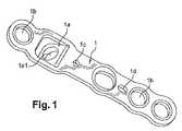
本発明にしたがって、プレート(1)は、上記プレートによって規定される平面に対して30°〜60°の間の角度αで傾斜するように少なくとも1つのねじ(2)を位置決めするのを可能にする少なくとも1つの特徴部(1a)を有する(図2)。 According to the invention, the plate (1) allows to position at least one screw (2) to be inclined at an angle α between 30 ° and 60 ° with respect to the plane defined by the plate. Having at least one feature (1a) (FIG. 2).
1つの実施形態において、特徴部(1a)は、プレートの切断および変形部分から生じる傾斜領域によって形成される。たとえば、変形は、切断/穴開け工程に続いて行われる。この傾斜領域はリブを構成し、これは、ねじ(2)の係合のための穴(1a1)を有する。傾斜リブ(1a)は、下記の記載に説明されるように、係合後に、ねじ(2)が2つの骨部分の圧縮を確実にするように、プレートの長さ方向において定められた部分上に形成される。 In one embodiment, the feature (1a) is formed by an inclined region resulting from the cut and deformed portion of the plate. For example, the deformation is performed following a cutting / drilling process. This inclined area constitutes a rib, which has a hole (1a1) for the engagement of the screw (2). The inclined rib (1a), as explained in the description below, on the part defined in the longitudinal direction of the plate so that after engagement the screw (2) ensures compression of the two bone parts. Formed.
1つの実施形態において、ねじ(2)の角度の方向を、約30°〜60°の間の角度にさせるために、特徴部(1a)は、傾斜した穴によって形成されることができる。このリブを自由に変形することが可能である場合には、リブ(1a)は、処置されるべき病状に依存して角度を適合することができることに留意されたい。言い換えると、角度は、手術室内で適切な器具で数度だけ執刀医が直接調節することができる。 In one embodiment, the feature (1a) can be formed by a slanted hole to cause the angle direction of the screw (2) to be between about 30 ° and 60 °. It should be noted that if it is possible to freely deform this rib, the rib (1a) can adapt its angle depending on the medical condition to be treated. In other words, the angle can be directly adjusted by the surgeon a few degrees with the appropriate instrument in the operating room.
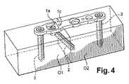
図3および4を参照すると、これらは、2つの骨部分(01)および(02)の間におけるプレート(1)の位置決めを示す。 With reference to FIGS. 3 and 4, these show the positioning of the plate (1) between two bone parts (01) and (02).
−骨切り術後に、プレートのモデルは、リブを有さないが、このリブの位置を決定するのを可能にする。 -After osteotomy, the model of the plate does not have a rib, but makes it possible to determine the position of this rib.
−リブの位置を決定して、執刀医は、適切なやすりで、対応する窪みを作る。 -Determine the position of the ribs, and the surgeon will make the corresponding depressions with a suitable file.
−リブ付プレートを適所に置いた後に、執刀医は、1つまたは2つのねじ(3)を、関節固定術の骨接合術部位でリブの側部に適合させる。一時固定用のピンを、場合により、適切な穴に位置決めすることができる。 -After placing the ribbed plate in place, the surgeon adapts one or two screws (3) to the side of the rib at the osteosynthesis site of the arthrodesis. In some cases, the pin for temporary fixing can be positioned in an appropriate hole.
−次いで、ねじ(2)は、骨折部位を圧縮するためにリブ(1a)の穴(1a1)に係合する。 The screw (2) then engages the hole (1a1) in the rib (1a) in order to compress the fracture site.
−ひとたび圧縮が得られると、執刀医は、1つまたはそれ以上の他の固定ねじ(3)をねじ込むことができ、一時保持ピンを取り外すことができる。 -Once compression is obtained, the surgeon can screw in one or more other fixing screws (3) and remove the temporary holding pins.
公知のように、このプレート(1)は、図3および4に見ることができるように、骨部分(01)および(02)内にねじ込まれる固定ねじ(3)の係合のために滑らかな且つ/またはねじ山を切った穴(1b)を有する。 As is known, this plate (1) is smooth due to the engagement of fixing screws (3) screwed into the bone parts (01) and (02), as can be seen in FIGS. And / or with a threaded hole (1b).
同様に、このプレート(1)は、上記プレート(1)の一時的な固定を確実にするためにピンを挿入するために少なくとも1つの凹部(1c)を有することができる。プレート(1)は、有利なことに、骨部分の一方(01)内にピンを挿入するための凹部(1c)と、他方の骨部分(02)内に別のピンを挿入するための別の凹部(1d)と、を有することができる。 Similarly, the plate (1) can have at least one recess (1c) for inserting a pin to ensure temporary fixation of the plate (1). The plate (1) advantageously has a recess (1c) for inserting a pin in one of the bone parts (01) and a separate for inserting another pin in the other bone part (02). And a recess (1d).
所望の圧縮効果を考慮して、上記に示されるように、凹部(1c)は円形穴によって形成され、その直径はピン(4)の直径に実質的に対応し、他方の凹部(1d)は楕円形のスロットによって形成されることができる。 In view of the desired compression effect, as indicated above, the recess (1c) is formed by a circular hole, the diameter of which corresponds substantially to the diameter of the pin (4), the other recess (1d) It can be formed by an elliptical slot.
したがって、これらの配置は、ねじ込み中にプレート(1)下で骨が摺動するのを可能にし、同時に、一般にプレートの軸に沿って、正確な方向への圧縮を確実にする。ピンは、いずれの公知のものであり、当業者には馴染みのある適切なタイプである。 These arrangements thus allow the bone to slide under the plate (1) during screwing, while at the same time ensuring compression in the correct direction, generally along the axis of the plate. The pins are of any known type and are of a suitable type familiar to those skilled in the art.
プレート(1)は、異なる幾何学的形状を有することができ、特に穴(1a)は、整列配置されることができるか、または、三角形または不等辺四辺形の頂点に沿って、全体にまたは部分的に、配列されることができる。三角形または不等辺四辺形にねじをこのように配列することは、固定具の安定性を改良する。 The plate (1) can have different geometric shapes, in particular the holes (1a) can be aligned, or entirely or along the vertices of a triangle or an unequal quadrilateral or In part, it can be arranged. Arranging the screws in this way in a triangular or unequal quadrilateral improves the stability of the fixture.
プレート(1)は、その幾何学的形状にかかわらず、骨の湾曲に適合するために長手方向に曲げることができ、それによって、ねじ(2)が互いの間で角度を形成するのを可能にすることにもまた留意されたい。 The plate (1) can be bent longitudinally to adapt to the curvature of the bone, regardless of its geometry, thereby allowing the screws (2) to form an angle between each other. Also note that
利点は、記載から明らかである。 The advantages are clear from the description.
Claims (6)
Translated fromJapaneseApplications Claiming Priority (3)
| Application Number | Priority Date | Filing Date | Title |
|---|---|---|---|
| FR0856694 | 2008-10-02 | ||
| FR0856694AFR2936700B1 (en) | 2008-10-02 | 2008-10-02 | ORTHOPEDIC IMPLANT IN THE FORM OF A PLATE TO BE FIXED BETWEEN TWO BONE PARTS |
| PCT/FR2009/051879WO2010037985A1 (en) | 2008-10-02 | 2009-10-02 | Orthopedic implant in the form of a plate to be fixed between two bone parts |
Publications (3)
| Publication Number | Publication Date |
|---|---|
| JP2012504444Atrue JP2012504444A (en) | 2012-02-23 |
| JP2012504444A5 JP2012504444A5 (en) | 2012-10-18 |
| JP5696268B2 JP5696268B2 (en) | 2015-04-08 |
Family
ID=40433892
Family Applications (1)
| Application Number | Title | Priority Date | Filing Date |
|---|---|---|---|
| JP2011529607AActiveJP5696268B2 (en) | 2008-10-02 | 2009-10-02 | Orthopedic implant in the form of a plate that connects and fixes between two bone parts |
Country Status (8)
| Country | Link |
|---|---|
| US (8) | US8556946B2 (en) |
| EP (2) | EP2334245B1 (en) |
| JP (1) | JP5696268B2 (en) |
| AU (1) | AU2009299628B2 (en) |
| CA (1) | CA2738892C (en) |
| ES (1) | ES2618102T3 (en) |
| FR (1) | FR2936700B1 (en) |
| WO (1) | WO2010037985A1 (en) |
Families Citing this family (55)
| Publication number | Priority date | Publication date | Assignee | Title |
|---|---|---|---|---|
| US7951176B2 (en) | 2003-05-30 | 2011-05-31 | Synthes Usa, Llc | Bone plate |
| US11259851B2 (en) | 2003-08-26 | 2022-03-01 | DePuy Synthes Products, Inc. | Bone plate |
| DE20321551U1 (en) | 2003-08-26 | 2007-12-27 | Synthes Gmbh | bone plate |
| US11291484B2 (en) | 2004-01-26 | 2022-04-05 | DePuy Synthes Products, Inc. | Highly-versatile variable-angle bone plate system |
| US8574268B2 (en) | 2004-01-26 | 2013-11-05 | DePuy Synthes Product, LLC | Highly-versatile variable-angle bone plate system |
| US8343199B2 (en)* | 2008-06-24 | 2013-01-01 | Extremity Medical, Llc | Intramedullary fixation screw, a fixation system, and method of fixation of the subtalar joint |
| US8328806B2 (en)* | 2008-06-24 | 2012-12-11 | Extremity Medical, Llc | Fixation system, an intramedullary fixation assembly and method of use |
| US8303589B2 (en) | 2008-06-24 | 2012-11-06 | Extremity Medical Llc | Fixation system, an intramedullary fixation assembly and method of use |
| US9017329B2 (en) | 2008-06-24 | 2015-04-28 | Extremity Medical, Llc | Intramedullary fixation assembly and method of use |
| US9044282B2 (en) | 2008-06-24 | 2015-06-02 | Extremity Medical Llc | Intraosseous intramedullary fixation assembly and method of use |
| US9289220B2 (en)* | 2008-06-24 | 2016-03-22 | Extremity Medical Llc | Intramedullary fixation assembly and method of use |
| US8313487B2 (en) | 2008-06-24 | 2012-11-20 | Extremity Medical Llc | Fixation system, an intramedullary fixation assembly and method of use |
| FR2936700B1 (en)* | 2008-10-02 | 2012-04-13 | Memometal Technologies | ORTHOPEDIC IMPLANT IN THE FORM OF A PLATE TO BE FIXED BETWEEN TWO BONE PARTS |
| US8986353B2 (en)* | 2009-07-09 | 2015-03-24 | Orthohelix Surgical Designs, Inc. | Osteotomy plate, plate driver and method for their use |
| WO2012058448A2 (en) | 2010-10-27 | 2012-05-03 | Toby Orthopaedics, Llc | System and method for fracture replacement of comminuted bone fractures or portions thereof adjacent bone joints |
| US9005255B2 (en)* | 2011-02-15 | 2015-04-14 | Orthohelix Surgical Designs, Inc. | Orthopedic compression plate |
| US8603091B2 (en)* | 2011-03-04 | 2013-12-10 | Stryker Trauma Ag | Pelvic and scapular bone plate and method for implantation |
| EP2725999B1 (en) | 2011-06-29 | 2019-04-10 | Nextremity Solutions, Inc. | Bone plate hybrid device |
| US9271772B2 (en) | 2011-10-27 | 2016-03-01 | Toby Orthopaedics, Inc. | System and method for fracture replacement of comminuted bone fractures or portions thereof adjacent bone joints |
| US9730797B2 (en) | 2011-10-27 | 2017-08-15 | Toby Orthopaedics, Inc. | Bone joint replacement and repair assembly and method of repairing and replacing a bone joint |
| US9060822B2 (en) | 2011-12-28 | 2015-06-23 | Orthohelix Surgical Designs, Inc. | Orthopedic compression plate and method of surgery |
| AU2013232339B2 (en)* | 2012-03-14 | 2017-11-02 | Synthes Gmbh | Pelvic bone plate |
| US9907588B2 (en) | 2012-09-06 | 2018-03-06 | Orthohelix Surgical Designs, Inc. | Orthopedic dual pocket compression plate and method of surgery |
| US9283008B2 (en) | 2012-12-17 | 2016-03-15 | Toby Orthopaedics, Inc. | Bone plate for plate osteosynthesis and method for use thereof |
| EP4252686A3 (en) | 2012-12-28 | 2023-12-27 | Paragon 28, Inc. | Alignment guide apparatus |
| US9358053B2 (en) | 2013-03-01 | 2016-06-07 | Stryker European Holdings I, Llc | Pelvic bone plate |
| US9333014B2 (en)* | 2013-03-15 | 2016-05-10 | Eduardo Gonzalez-Hernandez | Bone fixation and reduction apparatus and method for fixation and reduction of a distal bone fracture and malunion |
| US10245088B2 (en) | 2015-01-07 | 2019-04-02 | Treace Medical Concepts, Inc. | Bone plating system and method |
| AU2016215127B2 (en) | 2015-02-05 | 2020-12-03 | Paragon 28, Inc. | Bone plates, systems, and methods of use |
| USD819209S1 (en)* | 2015-08-07 | 2018-05-29 | Paragon 28, Inc. | Calc-slide bone plate |
| WO2016134160A1 (en) | 2015-02-18 | 2016-08-25 | Treace Medical Concepts, Inc. | Bone plating kit for foot and ankle applications |
| US10653467B2 (en)* | 2015-05-06 | 2020-05-19 | Treace Medical Concepts, Inc. | Intra-osseous plate system and method |
| FR3052047B1 (en) | 2016-06-02 | 2021-12-17 | Neosteo | IMPLANTABLE MEDICAL DEVICE FOR THE SOLIDARIZATION OF SEPARATED BONE PARTS WITH A VIEW OF THEIR FUSION |
| US10624686B2 (en) | 2016-09-08 | 2020-04-21 | DePuy Synthes Products, Inc. | Variable angel bone plate |
| US10905476B2 (en) | 2016-09-08 | 2021-02-02 | DePuy Synthes Products, Inc. | Variable angle bone plate |
| US10820930B2 (en) | 2016-09-08 | 2020-11-03 | DePuy Synthes Products, Inc. | Variable angle bone plate |
| EP3528716B1 (en) | 2016-10-24 | 2024-02-14 | Paragon 28, Inc. | Osteotomy systems |
| EP3585287B1 (en) | 2017-02-27 | 2024-11-13 | Paragon 28, Inc. | Intramedullary nail fixation systems |
| USD841166S1 (en)* | 2017-03-08 | 2019-02-19 | Paragon 28, Inc. | Hook plate |
| US10918431B2 (en) | 2017-03-30 | 2021-02-16 | Paragon 28, Inc. | Bone fixation system, assembly, implants, devices, alignment guides, and methods of use |
| WO2018187770A1 (en) | 2017-04-06 | 2018-10-11 | Extremity Medical, Llc | Orthopedic plate with modular peg and compression screw |
| EP3651699B1 (en) | 2017-07-11 | 2025-09-17 | Paragon 28, Inc. | Bone fixation system, assembly, implants, devices and insertion guides |
| USD847343S1 (en)* | 2017-11-02 | 2019-04-30 | Paragon 28, Inc. | Hook plate |
| ES2971443T3 (en)* | 2017-12-08 | 2024-06-05 | Paragon 28 Inc | Bone fixation and implant set |
| US11026727B2 (en) | 2018-03-20 | 2021-06-08 | DePuy Synthes Products, Inc. | Bone plate with form-fitting variable-angle locking hole |
| US10772665B2 (en) | 2018-03-29 | 2020-09-15 | DePuy Synthes Products, Inc. | Locking structures for affixing bone anchors to a bone plate, and related systems and methods |
| US11013541B2 (en) | 2018-04-30 | 2021-05-25 | DePuy Synthes Products, Inc. | Threaded locking structures for affixing bone anchors to a bone plate, and related systems and methods |
| EP3820382B1 (en) | 2018-07-11 | 2025-09-10 | Paragon 28, Inc. | Systems comprising alignment guides and implants |
| US11583323B2 (en) | 2018-07-12 | 2023-02-21 | Treace Medical Concepts, Inc. | Multi-diameter bone pin for installing and aligning bone fixation plate while minimizing bone damage |
| US10925651B2 (en) | 2018-12-21 | 2021-02-23 | DePuy Synthes Products, Inc. | Implant having locking holes with collection cavity for shavings |
| EP3923842A4 (en) | 2019-02-13 | 2022-11-23 | Paragon 28, Inc. | IMPLANTS, ALIGNMENT GUIDES, SYSTEMS AND METHODS OF USE |
| AU2020228309B2 (en) | 2019-02-28 | 2025-10-02 | Paragon 28, Inc. | Fusion systems, instruments, bone plates and methods of use |
| WO2021026357A1 (en) | 2019-08-07 | 2021-02-11 | Crossroads Extremity Systems, Llc | Bunion correction system and method |
| US11890039B1 (en) | 2019-09-13 | 2024-02-06 | Treace Medical Concepts, Inc. | Multi-diameter K-wire for orthopedic applications |
| US20240268874A1 (en)* | 2023-02-11 | 2024-08-15 | Brock A. Liden | Systems and methods for providing a salvation plate |
Citations (2)
| Publication number | Priority date | Publication date | Assignee | Title |
|---|---|---|---|---|
| JP2007507296A (en)* | 2003-09-29 | 2007-03-29 | スミス アンド ネフュー インコーポレーテッド | Bone plate with holes for interchangeably receiving locking screws and compression screws |
| US20080114360A1 (en)* | 2006-11-10 | 2008-05-15 | Da Frota Carrera Eduardo | Bone fastening plate |
Family Cites Families (148)
| Publication number | Priority date | Publication date | Assignee | Title |
|---|---|---|---|---|
| FR590290A (en)* | 1924-12-10 | 1925-06-13 | Collin & Cie | Osteosynthesis splint |
| US2486303A (en)* | 1948-04-29 | 1949-10-25 | Harry Herschel Leiter | Surgical appliance for bone fractures |
| USRE28841E (en)* | 1966-06-22 | 1976-06-08 | Synthes A.G. | Osteosynthetic pressure plate construction |
| USRE31628E (en)* | 1966-06-22 | 1984-07-10 | Synthes Ag | Osteosynthetic pressure plate construction |
| CH462375A (en)* | 1966-06-22 | 1968-09-15 | Synthes Ag | Osteosynthetic pressure plate |
| FR1538053A (en)* | 1967-08-18 | 1968-09-07 | Osteosynthesis plate combined with its key | |
| US3528085A (en)* | 1968-03-22 | 1970-09-08 | Walker Reynolds Jr | Bone compression plate |
| US3779240A (en)* | 1972-03-31 | 1973-12-18 | S Kondo | Compression plate for osteosynthesis |
| FR2362616A1 (en) | 1976-08-26 | 1978-03-24 | Duyck Jean | Metatarsal osteotomy anchor plate - has curved support with hooks, and holes for anchoring screws |
| CH645013A5 (en)* | 1980-04-14 | 1984-09-14 | Wenk Wilh Ag | Osteosynthetic COMPRESSION PLATE. |
| CH645264A5 (en)* | 1980-05-28 | 1984-09-28 | Straumann Inst Ag | FITTING WITH A PLATE AND SCREWS THAT FIX IT TO A BONE. |
| CH651192A5 (en)* | 1980-11-20 | 1985-09-13 | Synthes Ag | OSTEOSYNTHETIC DEVICE AND CORRESPONDING DRILL GAUGE. |
| CH650915A5 (en)* | 1981-03-16 | 1985-08-30 | Synthes Ag | DEVICE FOR STABILIZING THE AREA OF A BONE BREAK OR OSTEOTOMY. |
| DE8227727U1 (en)* | 1982-10-02 | 1982-12-16 | Howmedica International, Inc. Zweigniederlassung Kiel, 2301 Schönkirchen | OSTEOSYNTHESIS TOOLS FOR TREATING FRACTURES OF THE DENS AXIS |
| US4503737A (en)* | 1983-04-11 | 1985-03-12 | Digiovanni Donald | Threaded fastener removing tool |
| GB2158716B (en)* | 1984-05-18 | 1987-09-30 | Technomed Gmk | Bone joining plate |
| AT387711B (en)* | 1986-07-15 | 1989-03-10 | David Thomas | BONE FIXATION PLATE |
| DE3630862A1 (en)* | 1986-09-08 | 1988-03-17 | Mecron Med Prod Gmbh | Osteosynthesis part |
| DE8808123U1 (en)* | 1988-06-24 | 1988-09-22 | Herzberg, Wolfgang, Dr. med., 2000 Wedel | Tab screw for osteosynthesis of pertrochanteric fractures |
| DE3838774A1 (en)* | 1988-11-11 | 1990-05-17 | Mecron Med Prod Gmbh | SLIDING PLATE |
| US5105690A (en)* | 1991-03-29 | 1992-04-21 | Implant Innovations, Inc. | Manipulator-driver for holding and driving a screw-type article |
| US5304180A (en)* | 1992-01-17 | 1994-04-19 | Slocum D Barclay | Tibial osteotomy fixation plate |
| FR2693899B1 (en)* | 1992-07-24 | 1994-09-23 | Laboureau Jacques | Osteosynthesis plate clip. |
| JPH0748247Y2 (en)* | 1992-11-16 | 1995-11-08 | 株式会社タグチ | Bone joint |
| US5347894A (en)* | 1993-05-28 | 1994-09-20 | Pmt Corporation | Torque limiting device |
| US5558674A (en)* | 1993-12-17 | 1996-09-24 | Smith & Nephew Richards, Inc. | Devices and methods for posterior spinal fixation |
| FR2719211B1 (en)* | 1994-04-27 | 1996-07-19 | Mortier Jean Pierre | Equipment for correcting foot deformities. |
| US5674222A (en)* | 1994-06-01 | 1997-10-07 | Synthes (U.S.A.) | Forked plate |
| AU3207895A (en) | 1994-08-23 | 1996-03-14 | Spine-Tech, Inc. | Cervical spine stabilization system |
| US5601553A (en) | 1994-10-03 | 1997-02-11 | Synthes (U.S.A.) | Locking plate and bone screw |
| SE508120C2 (en)* | 1995-01-27 | 1998-08-31 | Robert J Medoff | Implantable device comprising a pin plate and pins |
| CA2189744C (en)* | 1995-03-27 | 2003-09-16 | Gilbert Talos | Bone plate |
| US5667510A (en)* | 1995-08-03 | 1997-09-16 | Combs; C. Robert | Joint fixation system and method |
| WO1997047251A1 (en)* | 1996-06-14 | 1997-12-18 | Depuy Ace Medical Company | Upper extremity bone plate |
| US5718705A (en)* | 1996-07-16 | 1998-02-17 | Sammarco; Giacomo J. | Internal fixation plate |
| US5827285A (en)* | 1996-12-12 | 1998-10-27 | Bramlet; Dale G. | Multipiece interfragmentary fixation assembly |
| US6139550A (en)* | 1997-02-11 | 2000-10-31 | Michelson; Gary K. | Skeletal plating system |
| US5904684A (en)* | 1997-04-16 | 1999-05-18 | Rooks; Robert L. | Device and method for simultaneous bilateral pelvic osteotomies |
| US5853413A (en)* | 1997-04-18 | 1998-12-29 | Bristol-Myers Squibb Company | Wrist fusion plate |
| ZA983955B (en)* | 1997-05-15 | 2001-08-13 | Sdgi Holdings Inc | Anterior cervical plating system. |
| FR2764183B1 (en) | 1997-06-09 | 1999-11-05 | Jacques Afriat | MATERIAL ALLOWING THE CORRECTION OF "HALLUX VALGUS" |
| US5938664A (en)* | 1998-03-31 | 1999-08-17 | Zimmer, Inc. | Orthopaedic bone plate |
| US6533786B1 (en)* | 1999-10-13 | 2003-03-18 | Sdgi Holdings, Inc. | Anterior cervical plating system |
| US6258089B1 (en)* | 1998-05-19 | 2001-07-10 | Alphatec Manufacturing, Inc. | Anterior cervical plate and fixation system |
| US6146382A (en)* | 1998-09-23 | 2000-11-14 | Spinal Concepts, Inc. | Occipito-cervical stabilization system and method |
| US6183475B1 (en)* | 1998-12-18 | 2001-02-06 | Sulzer Orthopedics Inc. | Distal femoral osteotomy system and method |
| AUPP830499A0 (en)* | 1999-01-22 | 1999-02-18 | Cryptych Pty Ltd | Method and apparatus for delivering bio-active compounds to specified sites in the body |
| DK1158915T3 (en)* | 1999-03-09 | 2004-11-08 | Synthes Ag | bone plate |
| AU3954200A (en)* | 1999-05-03 | 2000-11-17 | Medartis Ag | Blockable bone plate |
| DE29909025U1 (en)* | 1999-05-25 | 1999-11-04 | Lipat Consulting Ag, Basel | Osteosynthetic bone plate |
| CN1172634C (en)* | 1999-09-13 | 2004-10-27 | 库尔斯恩蒂斯股份公司 | Bone plating system |
| US6692503B2 (en) | 1999-10-13 | 2004-02-17 | Sdgi Holdings, Inc | System and method for securing a plate to the spinal column |
| EP1255498B1 (en)* | 2000-01-27 | 2005-11-23 | SYNTHES AG Chur | Bone plate |
| US6712820B2 (en)* | 2000-02-01 | 2004-03-30 | Hand Innovations, Inc. | Fixation plate system for dorsal wrist fracture fixation |
| US6440135B2 (en)* | 2000-02-01 | 2002-08-27 | Hand Innovations, Inc. | Volar fixation system with articulating stabilization pegs |
| US6379359B1 (en)* | 2000-05-05 | 2002-04-30 | University Of North Carolina At Chapel Hill | Percutaneous intrafocal plate system |
| US6576018B1 (en)* | 2000-06-23 | 2003-06-10 | Edward S. Holt | Apparatus configuration and method for treating flatfoot |
| SE525131C2 (en)* | 2001-01-15 | 2004-12-07 | Artimplant Ab | Implants for reconstruction of joints |
| US7044951B2 (en)* | 2001-02-12 | 2006-05-16 | Robert J. Medoff | Fracture fixation device in which a fixation pin is axially restrained |
| US6440131B1 (en) | 2001-03-09 | 2002-08-27 | Mayo Foundation For Medical Education And Research | Acetabular bone plate |
| US6565570B2 (en)* | 2001-03-14 | 2003-05-20 | Electro-Biology, Inc. | Bone plate and retractor assembly |
| WO2002076317A1 (en) | 2001-03-27 | 2002-10-03 | Ferree Bret A | Hinged anterior thoracic/lumbar plate |
| US20050049594A1 (en)* | 2001-04-20 | 2005-03-03 | Wack Michael A. | Dual locking plate and associated method |
| US7857836B2 (en) | 2005-07-13 | 2010-12-28 | Acumed Llc | Bone plates with movable locking elements |
| DE20122742U1 (en)* | 2001-05-28 | 2007-06-14 | Synthes Ag Chur, Chur | Bone plate for fixing proximal humerus fracture, has screw holes with partial internal threads or partial rotating taper grooves, where pitch of internal threads or taper grooves lies within range of specific millimeter |
| AUPR546601A0 (en)* | 2001-06-05 | 2001-06-28 | Australian Surgical Design And Manufacture Pty Limited | High tibial osteotomy device |
| US7316687B2 (en)* | 2001-08-24 | 2008-01-08 | Zimmer Technology, Inc. | Blade plate and instruments |
| FR2829920B1 (en) | 2001-09-26 | 2004-05-28 | Newdeal Sa | PLATE FOR FIXING THE BONES OF A JOINT, PARTICULARLY A METATARSO-PHALANGIAN JOINT |
| US20060235408A1 (en) | 2001-11-09 | 2006-10-19 | Wang Robert C | Apparatus and methods for bone fracture fixation |
| US20050090825A1 (en)* | 2002-02-15 | 2005-04-28 | Medartis Ag | Bone plate |
| ITBO20020224A1 (en)* | 2002-04-23 | 2003-10-23 | Citieffe Srl | STABILIZER SUPPORT FOR ADDITION AND SUBTRACTION OSTEOTOMIES |
| US8652142B2 (en)* | 2006-04-28 | 2014-02-18 | Acumed Llc | Osteotomy systems |
| US20050171544A1 (en)* | 2004-02-02 | 2005-08-04 | Acumed Llc | Bone plate with toothed aperture |
| US20040092929A1 (en)* | 2002-09-27 | 2004-05-13 | Zindrick Michael R. | Spinal plate with means to secure a graft |
| FR2846870B1 (en) | 2002-11-07 | 2005-07-01 | Fixano | OSTEOSYNTHESIS EQUIPMENT FOR THE TREATMENT OF A "LONG" CUBITUS |
| USD587370S1 (en) | 2003-02-26 | 2009-02-24 | Zimmer Gmbh | Bone plate |
| FR2851452B1 (en)* | 2003-02-26 | 2005-04-22 | Ct Pulse Orthopedics Ltd | MINI-BLADE ANATOMIC PLATE ALLOWING OSTEOSYNTHESIS OF THE FIRST PHALANGE |
| USD596294S1 (en) | 2003-02-26 | 2009-07-14 | Zimmer, Gmbh | Bone plate |
| DE602004001398T2 (en)* | 2003-03-20 | 2007-06-14 | Stryker Trauma S.A. | BONE CONNECTION DEVICE |
| BRPI0408769A (en) | 2003-03-26 | 2006-03-28 | Swiss Orthopedic Solutions Sa | lock bone plate |
| US7722653B2 (en)* | 2003-03-26 | 2010-05-25 | Greatbatch Medical S.A. | Locking bone plate |
| US7819903B2 (en) | 2003-03-31 | 2010-10-26 | Depuy Spine, Inc. | Spinal fixation plate |
| US7144252B2 (en)* | 2003-04-25 | 2006-12-05 | James Walton | Dental tool with shear pin handle |
| US7951176B2 (en)* | 2003-05-30 | 2011-05-31 | Synthes Usa, Llc | Bone plate |
| WO2006091827A2 (en) | 2005-02-25 | 2006-08-31 | Regents Of The University Of California | Device and template for canine humeral slide osteotomy |
| US7540874B2 (en) | 2004-05-27 | 2009-06-02 | Trimed Inc. | Method and device for use in osteotomy |
| GB2414673A (en)* | 2004-06-02 | 2005-12-07 | Vineet Dev Tandon | A bone plate |
| US20050277937A1 (en)* | 2004-06-10 | 2005-12-15 | Leung Takkwong R | Bone plating system |
| US7137987B2 (en)* | 2004-07-02 | 2006-11-21 | Wright Medical Technology, Inc. | Distal radius bone plating system with locking and non-locking screws |
| FR2873015B1 (en)* | 2004-07-15 | 2007-12-28 | Newdeal Sa Sa | FASTENING IMPLANT FOR THE OSTEOSYNTHESIS OF FRAGMENTS OF A FIRST FRACTURE OR OSTEOTOMIZED METATARSIS IN ITS PROXIMAL PART AND CORRESPONDING OSTEOSYNTHESIS METHOD |
| US20060058796A1 (en)* | 2004-09-14 | 2006-03-16 | Hartdegen Vernon R | Compression brace |
| US20060106387A1 (en)* | 2004-11-16 | 2006-05-18 | Depuy Spine, Inc. | Spinal plate system and method of use |
| US7166111B2 (en) | 2004-12-08 | 2007-01-23 | Depuy Spine, Inc. | Spinal plate and drill guide |
| US8118848B2 (en) | 2005-01-28 | 2012-02-21 | Orthohelix Surgical Designs, Inc. | Orthopedic plate for use in fibula repair |
| US8118846B2 (en) | 2005-01-28 | 2012-02-21 | Orthohelix Surgical Designs, Inc. | Orthopedic plates for use in clavicle repair and methods for their use |
| US7799061B2 (en) | 2005-01-28 | 2010-09-21 | Orthohelix Surgical Designs, Inc. | Orthopedic plate |
| ES2300967T3 (en)* | 2005-03-11 | 2008-06-16 | Orthofix S.R.L. | DEVICE FOR OSTEOSYNTHESIS OF PROXIMAL FRACTURES OF THE HUMER. |
| WO2006099766A1 (en)* | 2005-03-24 | 2006-09-28 | Medartis Ag | Bone plate |
| US20060235397A1 (en)* | 2005-03-31 | 2006-10-19 | Roy Sanders | Navicular fixation device |
| US7344538B2 (en)* | 2005-03-31 | 2008-03-18 | Depuy Products, Inc. | Mid-foot fixation plate |
| US20060241607A1 (en)* | 2005-03-31 | 2006-10-26 | Mark Myerson | Metatarsal fixation plate |
| US20060241608A1 (en)* | 2005-03-31 | 2006-10-26 | Mark Myerson | Plate for fusion of the metatarso-phalangeal joint |
| US7931680B2 (en)* | 2005-03-31 | 2011-04-26 | Depuy Products, Inc. | Plate for lengthening the lateral column of the foot |
| US7766948B1 (en) | 2005-05-05 | 2010-08-03 | Ebi, Llc | Bone fixation assembly |
| JP2007151674A (en) | 2005-12-01 | 2007-06-21 | Hidetoshi Onoe | Bone plate |
| US20070142920A1 (en)* | 2005-12-20 | 2007-06-21 | Niemi Willard J | Metatarsal implant |
| ES2298921T3 (en) | 2005-12-23 | 2008-05-16 | Aap Implantate Ag | OSEA PLATE. |
| US8523921B2 (en)* | 2006-02-24 | 2013-09-03 | DePuy Synthes Products, LLC | Tibial plateau leveling osteotomy plate |
| BRPI0601069B1 (en) | 2006-03-17 | 2014-10-14 | Gm Dos Reis Ind E Com Ltda | BONE BOARD |
| CA2679639A1 (en) | 2006-05-17 | 2007-11-22 | Gordon Slater | Ankle fusion plate |
| FR2905590B1 (en)* | 2006-09-11 | 2008-12-05 | Surge Foot | ARTHRODESIS PLATE OF A METATARSO-PHALANGEAL ARTICULATION. |
| US8187276B1 (en)* | 2006-09-26 | 2012-05-29 | Zahiri Christopher A | Odd angle internal bone fixation device for use in a transverse fracture of a humerus |
| US8636779B2 (en) | 2007-02-26 | 2014-01-28 | Life Spine, Inc. | Spine plate with configured bone screw bores |
| FR2912895B1 (en) | 2007-02-28 | 2009-05-01 | Small Bone Innovations Interna | MATERIAL OF ARTHODESIS |
| US8556944B2 (en) | 2007-07-31 | 2013-10-15 | Stryker Spine | System and method for vertebral body plating |
| US20090093849A1 (en) | 2007-10-03 | 2009-04-09 | Greg Grabowski | Metatarsal fixation system |
| EP2397094B1 (en)* | 2007-11-02 | 2013-06-26 | Biomet C.V. | Elbow fracture fixation system |
| JP2011510799A (en) | 2008-02-06 | 2011-04-07 | オステオメッド エル.ピー. | Articular process fracture fixation plate system for hand tubular bone |
| US8257403B2 (en) | 2008-02-19 | 2012-09-04 | Orthohelix Surgical Designs, Inc. | Orthopedic plate for use in the midfoot |
| US8257406B2 (en) | 2008-02-19 | 2012-09-04 | Orthohelix Surgical Designs, Inc. | Orthopedic plate for use on a single ray in the midfoot |
| US8167918B2 (en) | 2008-02-19 | 2012-05-01 | Orthohelix Surgical Designs, Inc. | Orthopedic plate for use in the MTP joint |
| US20090228048A1 (en) | 2008-03-10 | 2009-09-10 | Duncan Scott F M | Joint Fixation System For the Hand |
| US8652179B2 (en) | 2008-05-02 | 2014-02-18 | The Cleveland Clinic Foundation | Bone plate extender and extension system for bone restoration and methods of use thereof |
| US20110230884A1 (en) | 2008-06-24 | 2011-09-22 | Adam Mantzaris | Hybrid intramedullary fixation assembly and method of use |
| US20100121325A1 (en) | 2008-06-24 | 2010-05-13 | Jeff Tyber | Hybrid intramedullary fixation assembly and method of use |
| US8343199B2 (en) | 2008-06-24 | 2013-01-01 | Extremity Medical, Llc | Intramedullary fixation screw, a fixation system, and method of fixation of the subtalar joint |
| US8313487B2 (en) | 2008-06-24 | 2012-11-20 | Extremity Medical Llc | Fixation system, an intramedullary fixation assembly and method of use |
| US8303589B2 (en) | 2008-06-24 | 2012-11-06 | Extremity Medical Llc | Fixation system, an intramedullary fixation assembly and method of use |
| US9017329B2 (en) | 2008-06-24 | 2015-04-28 | Extremity Medical, Llc | Intramedullary fixation assembly and method of use |
| US9044282B2 (en) | 2008-06-24 | 2015-06-02 | Extremity Medical Llc | Intraosseous intramedullary fixation assembly and method of use |
| US8328806B2 (en) | 2008-06-24 | 2012-12-11 | Extremity Medical, Llc | Fixation system, an intramedullary fixation assembly and method of use |
| US20110125153A1 (en) | 2008-06-24 | 2011-05-26 | Jeff Tyber | Intramedullary fixation assembly and method of use |
| SE533632C2 (en)* | 2008-07-01 | 2010-11-09 | Swemac Innovation Ab | Device for internal fixation of the bone fragments in a bone fracture |
| US8167891B2 (en) | 2008-07-21 | 2012-05-01 | Osteomed Llc | System and method for fracture reduction |
| US8506641B2 (en) | 2008-09-03 | 2013-08-13 | The Cleveland Clinic Foundation | Arthrodesis implant for finger joints and related methods |
| FR2936700B1 (en)* | 2008-10-02 | 2012-04-13 | Memometal Technologies | ORTHOPEDIC IMPLANT IN THE FORM OF A PLATE TO BE FIXED BETWEEN TWO BONE PARTS |
| FR2936699B1 (en) | 2008-10-02 | 2012-01-13 | Memometal Technologies | ORTHOPEDIC IMPLANT IN THE FORM OF A PLATE TO BE FIXED BETWEEN TWO BONE PARTS |
| US8828063B2 (en) | 2008-11-19 | 2014-09-09 | Amei Technologies, Inc. | Fixation plate for use in the Lapidus approach |
| US8100983B2 (en) | 2008-11-25 | 2012-01-24 | Schulte Robert C | Intra-osseus fusion system |
| USD623745S1 (en) | 2009-02-17 | 2010-09-14 | Orthohelix Surgical Designs, Inc. | Orthopedic plate |
| US8246664B2 (en) | 2009-02-24 | 2012-08-21 | Osteomed Llc | Multiple bone fusion plate |
| US8529608B2 (en) | 2009-04-28 | 2013-09-10 | Osteomed Llc | Bone plate with a transfixation screw hole |
| US8986353B2 (en) | 2009-07-09 | 2015-03-24 | Orthohelix Surgical Designs, Inc. | Osteotomy plate, plate driver and method for their use |
| US8657820B2 (en) | 2009-10-12 | 2014-02-25 | Tornier, Inc. | Bone plate and keel systems |
| US20110087295A1 (en) | 2009-10-12 | 2011-04-14 | University Of Utah | Bone fixation systems |
| US8551107B2 (en) | 2009-10-15 | 2013-10-08 | Biomet, C.V. | Bending tool and method for reshaping a bone plate |
| US8535355B2 (en) | 2009-10-15 | 2013-09-17 | Biomet C.V. | Dorsal midfoot bone plate system and method |
| US8764807B2 (en) | 2010-06-10 | 2014-07-01 | Arthrex, Inc. | Calcaneus step plate |
- 2008
- 2008-10-02FRFR0856694Apatent/FR2936700B1/enactiveActive
- 2009
- 2009-10-02USUS12/918,071patent/US8556946B2/enactiveActive
- 2009-10-02WOPCT/FR2009/051879patent/WO2010037985A1/enactiveApplication Filing
- 2009-10-02EPEP09756159.1Apatent/EP2334245B1/enactiveActive
- 2009-10-02ESES09756159.1Tpatent/ES2618102T3/enactiveActive
- 2009-10-02AUAU2009299628Apatent/AU2009299628B2/enactiveActive
- 2009-10-02JPJP2011529607Apatent/JP5696268B2/enactiveActive
- 2009-10-02EPEP16202035.8Apatent/EP3170466B1/enactiveActive
- 2009-10-02CACA2738892Apatent/CA2738892C/enactiveActive
- 2013
- 2013-09-30USUS14/041,706patent/US9078713B2/enactiveActive
- 2015
- 2015-06-09USUS14/734,676patent/US9333013B2/enactiveActive
- 2016
- 2016-04-15USUS15/130,147patent/US10349988B2/enactiveActive
- 2019
- 2019-06-03USUS16/429,834patent/US11534212B2/enactiveActive
- 2021
- 2021-01-07USUS17/143,709patent/US10993751B1/enactiveActive
- 2022
- 2022-11-21USUS17/990,936patent/US20230084400A1/enactivePending
- 2025
- 2025-01-16USUS19/025,037patent/US20250152215A1/enactivePending
Patent Citations (2)
| Publication number | Priority date | Publication date | Assignee | Title |
|---|---|---|---|---|
| JP2007507296A (en)* | 2003-09-29 | 2007-03-29 | スミス アンド ネフュー インコーポレーテッド | Bone plate with holes for interchangeably receiving locking screws and compression screws |
| US20080114360A1 (en)* | 2006-11-10 | 2008-05-15 | Da Frota Carrera Eduardo | Bone fastening plate |
Also Published As
| Publication number | Publication date |
|---|---|
| US9333013B2 (en) | 2016-05-10 |
| US20210121213A1 (en) | 2021-04-29 |
| US20250152215A1 (en) | 2025-05-15 |
| FR2936700B1 (en) | 2012-04-13 |
| US10349988B2 (en) | 2019-07-16 |
| US11534212B2 (en) | 2022-12-27 |
| EP3170466A1 (en) | 2017-05-24 |
| US20110046681A1 (en) | 2011-02-24 |
| JP5696268B2 (en) | 2015-04-08 |
| ES2618102T3 (en) | 2017-06-20 |
| AU2009299628B2 (en) | 2014-05-01 |
| WO2010037985A1 (en) | 2010-04-08 |
| US20150265324A1 (en) | 2015-09-24 |
| US8556946B2 (en) | 2013-10-15 |
| EP2334245B1 (en) | 2016-12-07 |
| US20190282281A1 (en) | 2019-09-19 |
| US20160228164A1 (en) | 2016-08-11 |
| EP3170466B1 (en) | 2023-06-21 |
| US9078713B2 (en) | 2015-07-14 |
| US10993751B1 (en) | 2021-05-04 |
| US20230084400A1 (en) | 2023-03-16 |
| EP2334245A1 (en) | 2011-06-22 |
| CA2738892A1 (en) | 2010-04-08 |
| AU2009299628A1 (en) | 2010-04-08 |
| US20140052193A1 (en) | 2014-02-20 |
| FR2936700A1 (en) | 2010-04-09 |
| CA2738892C (en) | 2014-08-05 |
Similar Documents
| Publication | Publication Date | Title |
|---|---|---|
| JP2012504444A (en) | Orthopedic implant in the form of a plate to be fixed between two bone parts | |
| JP2012504444A5 (en) | ||
| JP6637212B2 (en) | Bone plate with dynamic elements | |
| JP6940488B2 (en) | Fitting spacer system and method | |
| ES2687519T3 (en) | Bone fixation device | |
| JP5713906B2 (en) | Orthopedic implant in the form of a plate fixed between two bone parts | |
| JP4550058B2 (en) | Anatomic distal radius fracture fixation plate and method of use thereof | |
| US10653464B2 (en) | Foot bone plate providing fixation and compression | |
| AU2015308660B2 (en) | Proximal bunion resection guides and plates and methods of use | |
| JP5547225B2 (en) | Fracture fixation system with subchondral joint surface support | |
| EP3091911A1 (en) | Resection guides, implants and methods | |
| EP3720368A1 (en) | Bone fixation assembly, implants and methods of use | |
| US12245948B2 (en) | Bone fusion plate and system and method for its use in the wrist | |
| TW201938116A (en) | Bone plate sized and shaped for fixation to phalangeal bone | |
| CN206979561U (en) | Ankle outside bone plate afterwards | |
| RU2254090C2 (en) | Fork plate for performing fractures and false joints osteosynthesis | |
| TW201919545A (en) | Variable angle locking rotation correction plate | |
| EP2938300B1 (en) | Orthopedic bone plate and locking tab apparatus | |
| RU2765329C1 (en) | Bone fixation system |
Legal Events
| Date | Code | Title | Description |
|---|---|---|---|
| A521 | Request for written amendment filed | Free format text:JAPANESE INTERMEDIATE CODE: A523 Effective date:20120830 | |
| A621 | Written request for application examination | Free format text:JAPANESE INTERMEDIATE CODE: A621 Effective date:20120830 | |
| RD03 | Notification of appointment of power of attorney | Free format text:JAPANESE INTERMEDIATE CODE: A7423 Effective date:20130618 | |
| RD04 | Notification of resignation of power of attorney | Free format text:JAPANESE INTERMEDIATE CODE: A7424 Effective date:20130628 | |
| A131 | Notification of reasons for refusal | Free format text:JAPANESE INTERMEDIATE CODE: A131 Effective date:20130823 | |
| A601 | Written request for extension of time | Free format text:JAPANESE INTERMEDIATE CODE: A601 Effective date:20131120 | |
| A602 | Written permission of extension of time | Free format text:JAPANESE INTERMEDIATE CODE: A602 Effective date:20131127 | |
| A601 | Written request for extension of time | Free format text:JAPANESE INTERMEDIATE CODE: A601 Effective date:20131217 | |
| A602 | Written permission of extension of time | Free format text:JAPANESE INTERMEDIATE CODE: A602 Effective date:20131225 | |
| A521 | Request for written amendment filed | Free format text:JAPANESE INTERMEDIATE CODE: A523 Effective date:20140123 | |
| TRDD | Decision of grant or rejection written | ||
| A01 | Written decision to grant a patent or to grant a registration (utility model) | Free format text:JAPANESE INTERMEDIATE CODE: A01 Effective date:20140523 | |
| A601 | Written request for extension of time | Free format text:JAPANESE INTERMEDIATE CODE: A601 Effective date:20140619 | |
| A602 | Written permission of extension of time | Free format text:JAPANESE INTERMEDIATE CODE: A602 Effective date:20140624 | |
| R155 | Notification before disposition of declining of application | Free format text:JAPANESE INTERMEDIATE CODE: R155 | |
| A521 | Request for written amendment filed | Free format text:JAPANESE INTERMEDIATE CODE: A523 Effective date:20140729 | |
| A61 | First payment of annual fees (during grant procedure) | Free format text:JAPANESE INTERMEDIATE CODE: A61 Effective date:20140731 | |
| A521 | Request for written amendment filed | Free format text:JAPANESE INTERMEDIATE CODE: A821 Effective date:20140729 | |
| R150 | Certificate of patent or registration of utility model | Ref document number:5696268 Country of ref document:JP Free format text:JAPANESE INTERMEDIATE CODE: R150 | |
| S111 | Request for change of ownership or part of ownership | Free format text:JAPANESE INTERMEDIATE CODE: R313113 | |
| R350 | Written notification of registration of transfer | Free format text:JAPANESE INTERMEDIATE CODE: R350 | |
| R250 | Receipt of annual fees | Free format text:JAPANESE INTERMEDIATE CODE: R250 | |
| R250 | Receipt of annual fees | Free format text:JAPANESE INTERMEDIATE CODE: R250 | |
| R250 | Receipt of annual fees | Free format text:JAPANESE INTERMEDIATE CODE: R250 | |
| R250 | Receipt of annual fees | Free format text:JAPANESE INTERMEDIATE CODE: R250 | |
| S111 | Request for change of ownership or part of ownership | Free format text:JAPANESE INTERMEDIATE CODE: R313113 | |
| S531 | Written request for registration of change of domicile | Free format text:JAPANESE INTERMEDIATE CODE: R313531 | |
| S533 | Written request for registration of change of name | Free format text:JAPANESE INTERMEDIATE CODE: R313533 | |
| R360 | Written notification for declining of transfer of rights | Free format text:JAPANESE INTERMEDIATE CODE: R360 | |
| R360 | Written notification for declining of transfer of rights | Free format text:JAPANESE INTERMEDIATE CODE: R360 | |
| R371 | Transfer withdrawn | Free format text:JAPANESE INTERMEDIATE CODE: R371 | |
| S111 | Request for change of ownership or part of ownership | Free format text:JAPANESE INTERMEDIATE CODE: R313113 | |
| S531 | Written request for registration of change of domicile | Free format text:JAPANESE INTERMEDIATE CODE: R313531 | |
| S533 | Written request for registration of change of name | Free format text:JAPANESE INTERMEDIATE CODE: R313533 | |
| R371 | Transfer withdrawn | Free format text:JAPANESE INTERMEDIATE CODE: R371 | |
| S111 | Request for change of ownership or part of ownership | Free format text:JAPANESE INTERMEDIATE CODE: R313113 | |
| R360 | Written notification for declining of transfer of rights | Free format text:JAPANESE INTERMEDIATE CODE: R360 | |
| R360 | Written notification for declining of transfer of rights | Free format text:JAPANESE INTERMEDIATE CODE: R360 | |
| R371 | Transfer withdrawn | Free format text:JAPANESE INTERMEDIATE CODE: R371 | |
| R360 | Written notification for declining of transfer of rights | Free format text:JAPANESE INTERMEDIATE CODE: R360 | |
| R350 | Written notification of registration of transfer | Free format text:JAPANESE INTERMEDIATE CODE: R350 | |
| R250 | Receipt of annual fees | Free format text:JAPANESE INTERMEDIATE CODE: R250 | |
| S531 | Written request for registration of change of domicile | Free format text:JAPANESE INTERMEDIATE CODE: R313531 | |
| S533 | Written request for registration of change of name | Free format text:JAPANESE INTERMEDIATE CODE: R313533 | |
| R350 | Written notification of registration of transfer | Free format text:JAPANESE INTERMEDIATE CODE: R350 | |
| R250 | Receipt of annual fees | Free format text:JAPANESE INTERMEDIATE CODE: R250 | |
| R250 | Receipt of annual fees | Free format text:JAPANESE INTERMEDIATE CODE: R250 | |
| R250 | Receipt of annual fees | Free format text:JAPANESE INTERMEDIATE CODE: R250 |