JP2012502731A - Inflammatory response suppression system and method - Google Patents
Inflammatory response suppression system and methodDownload PDFInfo
- Publication number
- JP2012502731A JP2012502731AJP2011527843AJP2011527843AJP2012502731AJP 2012502731 AJP2012502731 AJP 2012502731AJP 2011527843 AJP2011527843 AJP 2011527843AJP 2011527843 AJP2011527843 AJP 2011527843AJP 2012502731 AJP2012502731 AJP 2012502731A
- Authority
- JP
- Japan
- Prior art keywords
- leg
- reduced pressure
- treatment device
- encapsulated
- manifold member
- Prior art date
- Legal status (The legal status is an assumption and is not a legal conclusion. Google has not performed a legal analysis and makes no representation as to the accuracy of the status listed.)
- Granted
Links
Images


Classifications
- A—HUMAN NECESSITIES
- A61—MEDICAL OR VETERINARY SCIENCE; HYGIENE
- A61M—DEVICES FOR INTRODUCING MEDIA INTO, OR ONTO, THE BODY; DEVICES FOR TRANSDUCING BODY MEDIA OR FOR TAKING MEDIA FROM THE BODY; DEVICES FOR PRODUCING OR ENDING SLEEP OR STUPOR
- A61M1/00—Suction or pumping devices for medical purposes; Devices for carrying-off, for treatment of, or for carrying-over, body-liquids; Drainage systems
- A61M1/90—Negative pressure wound therapy devices, i.e. devices for applying suction to a wound to promote healing, e.g. including a vacuum dressing
- A61M1/91—Suction aspects of the dressing
- A61M1/915—Constructional details of the pressure distribution manifold
- A—HUMAN NECESSITIES
- A61—MEDICAL OR VETERINARY SCIENCE; HYGIENE
- A61F—FILTERS IMPLANTABLE INTO BLOOD VESSELS; PROSTHESES; DEVICES PROVIDING PATENCY TO, OR PREVENTING COLLAPSING OF, TUBULAR STRUCTURES OF THE BODY, e.g. STENTS; ORTHOPAEDIC, NURSING OR CONTRACEPTIVE DEVICES; FOMENTATION; TREATMENT OR PROTECTION OF EYES OR EARS; BANDAGES, DRESSINGS OR ABSORBENT PADS; FIRST-AID KITS
- A61F13/00—Bandages or dressings; Absorbent pads
- A61F13/02—Adhesive bandages or dressings
- A61F13/0203—Adhesive bandages or dressings with fluid retention members
- A—HUMAN NECESSITIES
- A61—MEDICAL OR VETERINARY SCIENCE; HYGIENE
- A61F—FILTERS IMPLANTABLE INTO BLOOD VESSELS; PROSTHESES; DEVICES PROVIDING PATENCY TO, OR PREVENTING COLLAPSING OF, TUBULAR STRUCTURES OF THE BODY, e.g. STENTS; ORTHOPAEDIC, NURSING OR CONTRACEPTIVE DEVICES; FOMENTATION; TREATMENT OR PROTECTION OF EYES OR EARS; BANDAGES, DRESSINGS OR ABSORBENT PADS; FIRST-AID KITS
- A61F13/00—Bandages or dressings; Absorbent pads
- A61F13/05—Bandages or dressings; Absorbent pads specially adapted for use with sub-pressure or over-pressure therapy, wound drainage or wound irrigation, e.g. for use with negative-pressure wound therapy [NPWT]
- A—HUMAN NECESSITIES
- A61—MEDICAL OR VETERINARY SCIENCE; HYGIENE
- A61F—FILTERS IMPLANTABLE INTO BLOOD VESSELS; PROSTHESES; DEVICES PROVIDING PATENCY TO, OR PREVENTING COLLAPSING OF, TUBULAR STRUCTURES OF THE BODY, e.g. STENTS; ORTHOPAEDIC, NURSING OR CONTRACEPTIVE DEVICES; FOMENTATION; TREATMENT OR PROTECTION OF EYES OR EARS; BANDAGES, DRESSINGS OR ABSORBENT PADS; FIRST-AID KITS
- A61F13/00—Bandages or dressings; Absorbent pads
- A61F13/14—Bandages or dressings; Absorbent pads specially adapted for the breast or abdomen
- A61F13/148—Abdomen bandages or bandaging garments
- A—HUMAN NECESSITIES
- A61—MEDICAL OR VETERINARY SCIENCE; HYGIENE
- A61M—DEVICES FOR INTRODUCING MEDIA INTO, OR ONTO, THE BODY; DEVICES FOR TRANSDUCING BODY MEDIA OR FOR TAKING MEDIA FROM THE BODY; DEVICES FOR PRODUCING OR ENDING SLEEP OR STUPOR
- A61M1/00—Suction or pumping devices for medical purposes; Devices for carrying-off, for treatment of, or for carrying-over, body-liquids; Drainage systems
- A61M1/71—Suction drainage systems
- A61M1/73—Suction drainage systems comprising sensors or indicators for physical values
- A—HUMAN NECESSITIES
- A61—MEDICAL OR VETERINARY SCIENCE; HYGIENE
- A61M—DEVICES FOR INTRODUCING MEDIA INTO, OR ONTO, THE BODY; DEVICES FOR TRANSDUCING BODY MEDIA OR FOR TAKING MEDIA FROM THE BODY; DEVICES FOR PRODUCING OR ENDING SLEEP OR STUPOR
- A61M1/00—Suction or pumping devices for medical purposes; Devices for carrying-off, for treatment of, or for carrying-over, body-liquids; Drainage systems
- A61M1/90—Negative pressure wound therapy devices, i.e. devices for applying suction to a wound to promote healing, e.g. including a vacuum dressing
- A61M1/91—Suction aspects of the dressing
- A61M1/916—Suction aspects of the dressing specially adapted for deep wounds
- A—HUMAN NECESSITIES
- A61—MEDICAL OR VETERINARY SCIENCE; HYGIENE
- A61M—DEVICES FOR INTRODUCING MEDIA INTO, OR ONTO, THE BODY; DEVICES FOR TRANSDUCING BODY MEDIA OR FOR TAKING MEDIA FROM THE BODY; DEVICES FOR PRODUCING OR ENDING SLEEP OR STUPOR
- A61M1/00—Suction or pumping devices for medical purposes; Devices for carrying-off, for treatment of, or for carrying-over, body-liquids; Drainage systems
- A61M1/90—Negative pressure wound therapy devices, i.e. devices for applying suction to a wound to promote healing, e.g. including a vacuum dressing
- A61M1/96—Suction control thereof
- A61M1/966—Suction control thereof having a pressure sensor on or near the dressing
- A—HUMAN NECESSITIES
- A61—MEDICAL OR VETERINARY SCIENCE; HYGIENE
- A61M—DEVICES FOR INTRODUCING MEDIA INTO, OR ONTO, THE BODY; DEVICES FOR TRANSDUCING BODY MEDIA OR FOR TAKING MEDIA FROM THE BODY; DEVICES FOR PRODUCING OR ENDING SLEEP OR STUPOR
- A61M27/00—Drainage appliance for wounds or the like, i.e. wound drains, implanted drains
- A61M27/002—Implant devices for drainage of body fluids from one part of the body to another
- G—PHYSICS
- G05—CONTROLLING; REGULATING
- G05B—CONTROL OR REGULATING SYSTEMS IN GENERAL; FUNCTIONAL ELEMENTS OF SUCH SYSTEMS; MONITORING OR TESTING ARRANGEMENTS FOR SUCH SYSTEMS OR ELEMENTS
- G05B13/00—Adaptive control systems, i.e. systems automatically adjusting themselves to have a performance which is optimum according to some preassigned criterion
- A—HUMAN NECESSITIES
- A61—MEDICAL OR VETERINARY SCIENCE; HYGIENE
- A61F—FILTERS IMPLANTABLE INTO BLOOD VESSELS; PROSTHESES; DEVICES PROVIDING PATENCY TO, OR PREVENTING COLLAPSING OF, TUBULAR STRUCTURES OF THE BODY, e.g. STENTS; ORTHOPAEDIC, NURSING OR CONTRACEPTIVE DEVICES; FOMENTATION; TREATMENT OR PROTECTION OF EYES OR EARS; BANDAGES, DRESSINGS OR ABSORBENT PADS; FIRST-AID KITS
- A61F13/00—Bandages or dressings; Absorbent pads
- A61F2013/00361—Plasters
- A61F2013/00365—Plasters use
- A61F2013/00536—Plasters use for draining or irrigating wounds
- A—HUMAN NECESSITIES
- A61—MEDICAL OR VETERINARY SCIENCE; HYGIENE
- A61M—DEVICES FOR INTRODUCING MEDIA INTO, OR ONTO, THE BODY; DEVICES FOR TRANSDUCING BODY MEDIA OR FOR TAKING MEDIA FROM THE BODY; DEVICES FOR PRODUCING OR ENDING SLEEP OR STUPOR
- A61M1/00—Suction or pumping devices for medical purposes; Devices for carrying-off, for treatment of, or for carrying-over, body-liquids; Drainage systems
- A61M1/14—Dialysis systems; Artificial kidneys; Blood oxygenators ; Reciprocating systems for treatment of body fluids, e.g. single needle systems for hemofiltration or pheresis
- A61M1/28—Peritoneal dialysis ; Other peritoneal treatment, e.g. oxygenation
- A61M1/285—Catheters therefor
- A—HUMAN NECESSITIES
- A61—MEDICAL OR VETERINARY SCIENCE; HYGIENE
- A61M—DEVICES FOR INTRODUCING MEDIA INTO, OR ONTO, THE BODY; DEVICES FOR TRANSDUCING BODY MEDIA OR FOR TAKING MEDIA FROM THE BODY; DEVICES FOR PRODUCING OR ENDING SLEEP OR STUPOR
- A61M2210/00—Anatomical parts of the body
- A61M2210/10—Trunk
- A61M2210/1021—Abdominal cavity
- A—HUMAN NECESSITIES
- A61—MEDICAL OR VETERINARY SCIENCE; HYGIENE
- A61M—DEVICES FOR INTRODUCING MEDIA INTO, OR ONTO, THE BODY; DEVICES FOR TRANSDUCING BODY MEDIA OR FOR TAKING MEDIA FROM THE BODY; DEVICES FOR PRODUCING OR ENDING SLEEP OR STUPOR
- A61M27/00—Drainage appliance for wounds or the like, i.e. wound drains, implanted drains
- Y—GENERAL TAGGING OF NEW TECHNOLOGICAL DEVELOPMENTS; GENERAL TAGGING OF CROSS-SECTIONAL TECHNOLOGIES SPANNING OVER SEVERAL SECTIONS OF THE IPC; TECHNICAL SUBJECTS COVERED BY FORMER USPC CROSS-REFERENCE ART COLLECTIONS [XRACs] AND DIGESTS
- Y10—TECHNICAL SUBJECTS COVERED BY FORMER USPC
- Y10T—TECHNICAL SUBJECTS COVERED BY FORMER US CLASSIFICATION
- Y10T29/00—Metal working
- Y10T29/49—Method of mechanical manufacture
- Y10T29/49826—Assembling or joining
Landscapes
- Health & Medical Sciences (AREA)
- Heart & Thoracic Surgery (AREA)
- Engineering & Computer Science (AREA)
- Biomedical Technology (AREA)
- Life Sciences & Earth Sciences (AREA)
- Animal Behavior & Ethology (AREA)
- General Health & Medical Sciences (AREA)
- Public Health (AREA)
- Veterinary Medicine (AREA)
- Vascular Medicine (AREA)
- Anesthesiology (AREA)
- Hematology (AREA)
- Otolaryngology (AREA)
- Ophthalmology & Optometry (AREA)
- Medical Informatics (AREA)
- Computer Vision & Pattern Recognition (AREA)
- Evolutionary Computation (AREA)
- Artificial Intelligence (AREA)
- Software Systems (AREA)
- Physics & Mathematics (AREA)
- General Physics & Mathematics (AREA)
- Automation & Control Theory (AREA)
- External Artificial Organs (AREA)
- Surgical Instruments (AREA)
- Media Introduction/Drainage Providing Device (AREA)
Abstract
Translated fromJapaneseDescription
Translated fromJapanese関連出願
本発明は、2008年9月18日に出願された米国暫定特許出願第61/098,030号「流体除去システム及び方法」の、35USC§119(e)に規定の利益を請求する。この出願は、すべての目的で、ここに引用されている。RELATED APPLICATIONS The present invention claims the benefits specified in 35 USC §119 (e) of US Provisional Patent Application No. 61 / 098,030 “Fluid Removal System and Method” filed on September 18, 2008. This application is incorporated herein for all purposes.
本発明は、一般的に、医療システムに関し、特に、患者の炎症反応の抑制システム及び方法に関する。 The present invention relates generally to medical systems, and more particularly to a system and method for suppressing a patient's inflammatory response.
炎症反応の一つのタイプは、全身性炎症反応症候群(SIRS)である。SIRSは、疾病(外傷、感染症、火傷など)に対する深刻な全身性反応として定義されており、異常に上下する体温、分当たり90拍より多い心拍数、分当たり20呼吸より多い呼吸数または動脈血中の二酸化炭素濃度の低減、及び大きく上下する、又は10%を超える未発達好中球を含む白血球数、といった2またはそれ以上の症状群の存在によって示される急性炎症反応を引き起こす。Merriam−Webster’s Medical Dictionary(Springfield,Mo.:Merriam−Webster,Inc.,2006),q.v.,“Systemic inflammatory response syndrome.”SIRSは特別なものではなく、虚血、炎症、外傷、感染、あるいはいくつかの傷害の組み合わせによって生じることがある。敗血症は、SIRSの下位範疇であり、実証あるいは推定される感染症に加えた、SIRSの存在として規定することができる。 One type of inflammatory response is systemic inflammatory response syndrome (SIRS). SIRS is defined as a serious systemic response to a disease (trauma, infection, burn, etc.), with abnormally rising or falling body temperature, a heart rate greater than 90 beats per minute, a respiratory rate greater than 20 breaths per minute or arterial blood Causes an acute inflammatory response, as indicated by the presence of two or more groups of symptoms, such as a reduction in the concentration of carbon dioxide and white blood cell counts that greatly increase or decrease or contain more than 10% of undeveloped neutrophils. Merriam-Webster's Medical Dictionary (Springfield, Mo .: Merriam-Webster, Inc., 2006), q. v. “Systematic response response syndrome.” SIRS is not special and may be caused by ischemia, inflammation, trauma, infection, or a combination of several injuries. Sepsis is a subcategory of SIRS and can be defined as the presence of SIRS in addition to a demonstrated or presumed infection.
病因に関係なく、SIRSは通常同じ病態生理学的特性を有しており、これは、炎症あるいは炎症カスケードを誘発するときに若干異なっている。炎症カスケードは、体液性及び細胞性反応、相補体、及びサイトカインカスケードを含む複雑なプロセスである。炎症誘発性刺激は、組織と直接的に作用して、SIRSを助長すると考えられている。検査を受けていないSIRSは、腹部筋区画症候群(ACS)、臓器機能不全、多臓器機能不全(MODS)、多臓器不全症(MOF)、及び死を引き起こすことがある。 Regardless of the etiology, SIRS usually have the same pathophysiological characteristics, which are slightly different when inducing inflammation or an inflammatory cascade. The inflammatory cascade is a complex process involving humoral and cellular responses, complements, and cytokine cascades. Proinflammatory stimuli are thought to act directly on tissues and promote SIRS. Unexamined SIRS can cause abdominal compartment syndrome (ACS), organ dysfunction, multiple organ dysfunction (MODS), multiple organ dysfunction (MOF), and death.
多くの場合、SIRSが深刻であれば、治療介入が必要になる。例えば、SIRSがACSを引き起こす、あるいは引き起こし始めると、外科的減圧術を用いることがある。外科的減圧術は、開腹術を伴い、外科医は患者の胸骨から恥骨近傍へ胸側に正中切開を行う。その時、腹腔内容物が開放されて、腹腔を超えて広がる。このタイプの治療介入は、このような手術に関連して、費用のかかる長期の病院生活が必要であり、罹患率と死亡率が高く、その結果、介入が厳しいため、開腹を伴う介入の決定をできるだけ長く遅らせることがしばしばである。 In many cases, if SIRS is severe, therapeutic intervention is required. For example, if SIRS causes or begins to cause ACS, surgical decompression may be used. Surgical decompression involves a laparotomy, and the surgeon makes a midline incision on the chest side from the patient's sternum to the vicinity of the pubic bone. At that time, the contents of the abdominal cavity are released and spread beyond the abdominal cavity. This type of therapeutic intervention requires an expensive long-term hospital life in connection with such an operation, and because of the high morbidity and mortality resulting in severe interventions, the decision to intervene with laparotomy Is often delayed as long as possible.
SIRSおよびその他の炎症反応を抑制することが望まれている。更に、一般的には、できる限り早く、できる限り費用対効果が良くなるように炎症反応を抑制することが望まれている。 It is desirable to suppress SIRS and other inflammatory responses. Furthermore, it is generally desirable to suppress the inflammatory response so as to be as cost effective as possible as soon as possible.
ここに述べた実施例のシステムと方法によって医学的治療システム及び方法に関する問題に取り組んでいる。一の実施例によれば、患者の腹腔内における全身性炎症反応を抑制する方法は、患者の腹腔内へ治療デバイスを展開させるステップと;外部減圧源を治療デバイスに流体連結させて、腹腔内に減圧を提供するステップと;外部減圧源からの減圧を治療デバイスに提供するステップと;炎症反応を促進する刺激を腹腔内から取り除いて全身性炎症反応を抑制するステップと;を具える。 The exemplary systems and methods described herein address the problems associated with medical treatment systems and methods. According to one embodiment, a method of suppressing a systemic inflammatory response in a patient's abdominal cavity includes deploying a treatment device into the patient's abdominal cavity; fluidly connecting an external reduced pressure source to the treatment device; Providing a reduced pressure to the treatment device; removing stimuli that promote the inflammatory response from the abdominal cavity to suppress the systemic inflammatory response.
別の実施例によれば、患者の腹腔内において全身性炎症反応を抑制するシステムが、患者の腹腔内に展開させる治療デバイスを具える。この治療デバイスは、最小限の侵襲性治療デバイスであっても良い。患者の腹腔内において全身性炎症反応を抑制するシステムは、更に、患者の上皮の一部に配置して、腹腔の上に空気式シールを形成するように作動するシーリング部材と;減圧を供給する外部減圧源と;減圧源と連結インターフェースを流体連結する減圧送達管と;を具える。減圧源、減圧送達管、及び治療デバイスは、外部減圧源から治療デバイスへ減圧を提供して、炎症反応を促進する刺激流体を腹腔から取り除くよう作動する。 According to another embodiment, a system for suppressing a systemic inflammatory response within a patient's abdominal cavity includes a therapeutic device that is deployed within the patient's abdominal cavity. The treatment device may be a minimally invasive treatment device. A system for suppressing a systemic inflammatory response within a patient's abdominal cavity further provides a sealing member disposed on a portion of the patient's epithelium and operative to form a pneumatic seal over the abdominal cavity; An external vacuum source; and a vacuum delivery tube that fluidly connects the vacuum source and the coupling interface. The reduced pressure source, the reduced pressure delivery tube, and the treatment device operate to provide reduced pressure from the external reduced pressure source to the treatment device to remove stimulating fluid from the abdominal cavity that promotes an inflammatory response.
別の実施例によれば、患者の腹腔内において全身性炎症反応を抑制する方法が:患者の腹腔内に減圧治療デバイスを展開させ、外部減圧源を減圧治療デバイスに流体連結して、腹腔内に減圧を提供するステップを具える。全身性炎症反応を抑制する方法は更に、外減圧源からの減圧を減圧治療デバイスに提供するステップと;炎症を促進する刺激流体を腹腔から除去し、腹腔に減圧治療を提供して全身性炎症反応を抑制するステップと;を具える。 According to another embodiment, a method for suppressing a systemic inflammatory response in a patient's abdominal cavity includes: deploying a reduced pressure treatment device in the patient's abdominal cavity and fluidly connecting an external reduced pressure source to the reduced pressure treatment device; Providing a step of providing a vacuum. The method of suppressing a systemic inflammatory response further includes providing a reduced pressure treatment device with reduced pressure from an external reduced pressure source; removing stimulation fluid that promotes inflammation from the abdominal cavity and providing reduced pressure treatment to the abdominal cavity to systemic inflammation Suppressing the reaction; and
この実施例のその他の目的、特徴、及び利点は、図面と詳細な説明を参照して明らかになる。 Other objects, features and advantages of this embodiment will become apparent with reference to the drawings and detailed description.
以下の実施例の詳細な説明においては、その一部を成す添付図面を参照している。これらの実施例は、当業者が本発明を実施できるように十分に詳細に記載されており、その他の実施例を用いることができ、本発明の精神または範囲から外れることなく、論理構成、機械的、電気的、及び化学的変更を行い得ると理解される。ここに述べた実施例を当業者が実施するのに必要でない詳細を省くために、この記載は、当業者に公知の所定の情報は削除することができる。以下の詳細な説明は、従って、限定を意味するものでなく、実施例の範囲は特許請求の範囲によってのみ規定される。 In the following detailed description of the embodiments, reference is made to the accompanying drawings that form a part hereof. These embodiments are described in sufficient detail to enable those skilled in the art to practice the invention, and other embodiments can be used without departing from the spirit or scope of the invention. It is understood that mechanical, electrical, and chemical changes can be made. To omit details not necessary for one skilled in the art to practice the embodiments described herein, this description may omit certain information known to those skilled in the art. The following detailed description is therefore not meant to be limiting and the scope of the examples is defined only by the claims.
ここに記載したシステム及び装置によれば、全身性炎症反応及び内部組織部位における局所炎症反応を含む炎症反応の抑制を行うことができる。ここで用いられている「炎症反応の抑制」とは、炎症反応を防ぐまたは和らげることを含む。炎症反応の抑制は、炎症環境の治療を含めて様々な方法で行うことができる。炎症環境の治療は、例えば、流体、内部組織部位あるいはその近傍における組織のかん流の強化、あるいは減圧治療の提供、といった炎症を促進する刺激を除去するあるいは和らげることを含む。特に記載していない限り、ここで使用するとおり、「又は」は、相互に排他的である必要はない。より特定の実施例として、炎症反応の抑制は、サイトカイン、ケモカイン、及びその他の刺激物の内部組織部位近傍からの除去によって行うことができる。このアプローチは、除去速度を上げることを含む。より特定した例としては、炎症反応の抑制は、かん流の強化などの局部組織の健康状態を改善して、炎症を促進するシグナリングを減らし、これによってカスケード源を切断し、物理的反応を防止することによって行われる。このアプローチは、出現速度の低減を含む。より特定した例としては、炎症反応の抑制は、抗炎症シグナルと、作用薬あるいは拮抗薬として作用する、あるいは一般的に炎症を促進するサイトカインのレセプタ部位をブロックするサイトカインの生成を増やすことによって行われる。この例は、恒常性を修復し、炎症の生理学的反応を鈍くするのを助け、反応の中和を含む。 According to the system and apparatus described herein, it is possible to suppress inflammatory reactions including systemic inflammatory reactions and local inflammatory reactions in internal tissue sites. As used herein, “suppression of inflammatory response” includes preventing or relieving the inflammatory response. Inhibition of the inflammatory response can be accomplished in a variety of ways, including treatment of the inflammatory environment. Treatment of the inflammatory environment includes removing or mitigating stimuli that promote inflammation, such as, for example, enhancing fluid perfusion, tissue perfusion at or near internal tissue sites, or providing reduced pressure therapy. Unless otherwise stated, as used herein, “or” need not be mutually exclusive. As a more specific example, suppression of the inflammatory response can be achieved by removal of cytokines, chemokines, and other stimuli from the vicinity of the internal tissue site. This approach involves increasing the removal rate. As a more specific example, suppression of the inflammatory response improves local tissue health, such as enhanced perfusion, and reduces signaling that promotes inflammation, thereby severing the cascade source and preventing physical responses Is done by doing. This approach involves a reduction in appearance speed. As a more specific example, suppression of the inflammatory response is accomplished by increasing the production of cytokines that block anti-inflammatory signals and cytokine receptor sites that act as agonists or antagonists, or generally promote inflammation. Is called. Examples of this include restoring homeostasis, slowing down the physiological response of inflammation, and neutralizing the response.
図に示すシステムと装置を用いて、ヒト、動物、またはその他の生命体の身体組織である内部組織部位を治療することができる。内部組織部位は、例えば、腹腔などの体腔といった、組織空間である。内部組織部位は、患者の腕、脚、頭蓋、またはその他の部位などその他の組織空間に位置していても良い。組織空間に対しては、図に示すシステム及びデバイスを配置して除去する数々のアプローチを用いることができる。例えば、図に示すシステム及びデバイスは、(1)開放創傷を介して配置及び除去する(例えば、図1参照);(2)開放創傷を介して配置し、一又はそれ以上のデバイスによる切開部を介して除去する(例えば、図3A−5B参照);(3)一又はそれ以上のデバイスによる切開部を介して配置及び除去する(例えば、図3A−5B参照);ことができる。 The system and apparatus shown in the figures can be used to treat internal tissue sites that are the body tissue of a human, animal, or other living organism. The internal tissue site is a tissue space such as a body cavity such as an abdominal cavity. The internal tissue site may be located in other tissue spaces such as the patient's arm, leg, skull, or other site. For tissue spaces, a number of approaches can be used to place and remove the systems and devices shown in the figure. For example, the system and device shown in the figure are (1) placed and removed through an open wound (see, eg, FIG. 1); (2) placed through an open wound and incised by one or more devices. (See eg FIGS. 3A-5B); (3) placed and removed via an incision with one or more devices (see eg FIGS. 3A-5B);
図1A−1Dを参照すると、患者の腹腔103内といった内部組織部位104における、例えば全身性炎症反応などの炎症反応を抑制するシステム100の一実施例が示されている。システム100は、治療デバイス102を具える。患者の腹腔103内の炎症反応を抑制するシステム100は、全身性炎症反応症候群を含む炎症反応を抑制する治療を送達し、腹筋区画症候群を回避する助けとなる。腹腔内圧が上昇することなく炎症反応が生じ、ある特別な場合は、非限定的な例で、炎症反応制御の抑制は、腹腔103全体の圧力上昇を抑えること、あるいは少なくとも腹腔内圧力を15mmHgより低く、好ましくは13mmHgより低く、より好ましくは10mmHgより低く抑えることを含む。正常な腹腔内圧力は、約0−5mmHgの範囲であると言われている。腹腔内圧力は、腹部区画にカテーテルを直接挿入することによって、あるいは間接的には、膀胱、胃あるいはその他の体腔内の圧力をモニタリングすることによってモニタすることができる。 1A-1D, one embodiment of a
システム100は、患者の内部組織部位104に関連する炎症環境を治療することによって炎症を制御する。炎症環境の治療には、上述のアプローチが含まれ、これには、炎症を促進する刺激の除去、内部組織部位104におけるあるいはこの近傍での組織のかん流の強化、あるいは、減圧治療の提供が含まれる。一の実施例では、システム100は、ほぼすべての炎症刺激を取り除くように動作し、これには、腹腔103内の大半の流体を除去して、炎症環境を中断するあるいは局所的な組織の健康状態を改善することを含む。別の実施例では、システム100は、炎症刺激を和らげるように動作して、炎症環境を中断するあるいは局所的な組織の健康状態を改善することができる。腹腔103に展開させた治療デバイス102を用いて治療を提供することで、腹膜カテーテル流体中で測定した、炎症刺激のレベルまたはインターロイキン−6(IL−6)やTNF−αなどの媒介物のレベルを低減することができる。治療デバイス102は、時間分(T)を通して炎症を促進する刺激である流体を内部組織部位104近傍から除去するシステム及び方法と共に使用することができる。この治療を行う時間は、30分乃至50時間またはそれ以上の範囲であっても良い。例えば炎症を促進する刺激を和らげるといった炎症環境を治療することによって、炎症反応の開始を、例えば防止するまたは遅らせるなど、抑制し、重症度を低減することができる。
治療デバイス102は、高い信頼性を持って、腹部流体または炎症を促進する刺激を除去する。システム100は、通常はクロッグが生じず、さもなければ使用と共に効果が減少する。治療デバイス102によって提供される減圧治療は、腹腔103内により良好な組織かん流を提供し、これは炎症反応を抑制する追加手段として考えることができる。治療デバイス102は、とりわけ、流体を管理し、浮腫を減らし、炎症反応に続いて生じる多臓器不全(MODS)が進むリスクを低減する助けとなる。治療デバイス102は、腹腔103内でのアプリケーションに使用して、腸浮腫を治療することができる。治療デバイス102はまた、部分的開腹を行う場合にも使用することができる。 The
治療を受ける内部組織部位104は、人、動物あるいはその他の有機体の身体組織である。本実施例では、内部組織部位104が、体腔、特に腹腔103内の組織を含み、腹腔内容物または腹腔近傍にある組織を含む。別のアプリケーションでは、内部組織部位は患者の腕、脚、頭蓋またはその他の部位の組織空間又は区画に位置している。 The
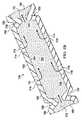
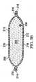
図に示すように、治療装置102は患者の腹腔103内に配置されて、局部的あるいは全身性の炎症反応の抑制を助けている。この実施例では、治療装置102は開腹部を介して展開させるあるいは除去するためのものである。治療装置102は、複数のカプセル化した脚部材106を具え、この部材は複数のカプセル化した脚部材106が配置される表面を形成している腹腔内容物に支持されている。一又はそれ以上の複数のカプセル化した脚部材106は、第1の結腸傍溝108内あるいはその近傍に配置されており、複数のカプセル化した脚部材106のうちの一またはそれ以上が、第2の結腸傍溝110内またはその近傍に配置されている。複数のカプセル化した脚部材106は、中央連結部材112に連結されており、複数のカプセル化した脚部材106と中央連結部材112との間は流体連通している。複数のカプセル化した脚部材106と中央連結部材112は双方共に、穿孔114、116、118、120が形成されており、腹腔103に流体を通過させる。穿孔114、116、118、120は、例えば、円形開口、矩形開口、多角形、その他など、どのような形状でも良いが、この実施例では、スリットあるいは直線状カット部分として表わされている。一又はそれ以上の穿孔114、116、118、120は、代替の実施例では除いても良い。 As shown, the
マニフォールド122またはマニフォールドパッドは、治療装置102に減圧を送達する。代替的に、連結インターフェース(例えば、図3Aの連結インターフェース220)を、治療装置102に連結して、減圧を供給する(及び流体を除去する)こともできる。シーリング部材124は、腹腔103又は体腔開口126の上に空気式シールを提供する。一又はそれ以上の皮膚閉合デバイスを患者の上皮134又は腹腔壁(図示せず)の上においても良い。減圧送達管130に連結された減圧インターフェース128を介して、減圧がマニフォールド122へ送達される。外部減圧源132は、減圧送達管130へ減圧を送達する。ここで用いられているように、「連結された」の用語は、別のものを介して連結することと、直接連結することを含む。また、「連結された」の用語は、同じ素材でできている部品の各々によって、別の部品と連続している二またはそれ以上の部品に及ぶ。また、「連結された」の用語は、化学接着剤を介するといった化学的連結、機械的連結、熱的連結、あるいは電気的連結を含む。流体連結とは、流体が指定された部分あるいは位置間で連通することを意味する。 The manifold 122 or manifold pad delivers reduced pressure to the
減圧を内部組織部位104に適用して、腹水、サイトカイン、滲出液、血液(外傷の場合)、あるいは内部組織部位104からのその他の流体を含む、炎症を促進する刺激を除去することができる。ここで用いているように、「減圧」は、一般的に、治療を施している組織部位における周囲圧力より低い圧力を意味する。ほとんどの場合、この減圧は、患者が位置しているところの大気圧より低くなるであろう。代替的に、減圧は組織部位における静水圧より低くても良い。特に表示がない限り、ここに述べた圧力の値はゲージ圧である。 Reduced pressure can be applied to the
マニフォールド122は、中央連結部材112の近傍に位置している。マニフォールド122は、様々な形をとることができる。ここで用いている「マニフォールド」の用語は、内部組織部位へ減圧を適用する、流体を送達する、あるいは内部組織部位104から流体を除去することを補助するために設けた物質または構造を意味する。マニフォールド122は、通常、マニフォールド122の周囲の内部組織部位104から及び中央連結部材112を通って提供したあるいは除去した流体の分布を改善するべく内部接続された複数のフローチャネルまたは通路を具える。マニフォールド122は、内部組織部位104と接触させて配置することができ、内部組織部位104へ減圧を送達できる生体適合性材料であっても良い。マニフォールド122の例には、限定することなく、フローチャネルを形成するように構成した構造要素、開放気泡フォームなどの気泡フォーム、多孔性組織の集合、液体、ゲル、及びフローチャネルを含むまたはフローチャネルを含むように硬化させたフォームを有する装置が含まれる。マニフォールド122は多孔性でも良く、フォーム、ガーゼ、フェルトマット、または特定の生物学的アプリケーションに適したその他の材料でできていても良い。一の実施例では、マニフォールド122は多孔性フォームであり、複数の連続気泡またはフローチャネルとして作用するポアを含む。多孔性フォームは、ポリウレタン、開放気泡、テキサス州サンアントニオ所在のKinetic Concepts,Incorporated 社製のGranuFoam(登録商標)などの網状フォームであってもよい。別の実施例では、「独立気泡」を含んでも良い。いくつかの場合、マニフォールド122を用いて、薬剤、抗菌材、成長ファクタ、及び様々な溶液といった流体を内部組織部位104に配分するのに使用することもできる。吸水性材料、ウイッキング材、疎水性材料及び親水性材料など、その他の層をマニフォールド122の中にあるいは上に含めるようにしても良い。 The manifold 122 is located in the vicinity of the central connecting
シーリング部材124は、例えば腹腔103などの体腔開口126の上に配置されており、開キャビティ減圧システム100に適した空気式シールを提供して、内部組織部位104で減圧を保持する。シーリング部材124は、中央連結部材112上のマニフォールド122を固定するのに用いられるカバーであっても良い。シーリング部材124は、不浸透性又は半浸透性であっても良い。シーリング部材124は、体腔開口126の上にシーリング部材124を装着した後、内部組織部位104で減圧を維持することができる。シーリング部材124はフレキシブルな上掛け、またはシリコーンベースの化合物、アクリル、ヒドロゲルあるいはヒドロゲル形成材、又は、内部組織部位104に減圧を適用するのに望ましい不浸透性又は浸透性特性を具えるその他の生体適合性材料でできたフィルムであっても良い。 The sealing
シーリング部材124はさらに、患者の上皮134にシーリング部材124を固定する取り付け装置131を具えていても良い。取り付け装置131はさまざまな形をとる。例えば、接着剤層136をシーリング部材124の周辺に沿って、あるいはシーリング部材124のいずれかの部分に沿って配置し、直接的あるいは間接的に、患者の上皮134と共に空気式シールを提供することができる。接着剤層136は、シーリング部材124に予め貼っておいて、解放可能な裏打ちで覆っておいても良く、あるいは貼付時に取り外す部材(図示せず)であってもよい。 The sealing
減圧インターフェース128は、一例として、マニフォールド122からの流体を減圧送達管130に通過させ、またその逆を行うポートまたはコネクタ138であっても良い。例えば、マニフォールド122と治療デバイス102を用いて内部組織部位104から回収した流体は、コネクタ138を介して減圧送達管130に入ることができる。別の実施例では、開キャビティ減圧システム100は、コネクタ138を除いて、減圧送達管130がシーリング部材124とマニフォールド122に直接入るようにしても良い。減圧送達管130は、医療用管またはチューブあるいは、減圧および流体を移送するその他の手段であっても良い。減圧送達管130は、減圧の送達と流体の除去を容易にするマルチルーメン部材であってもよい。一の実施例では、減圧送達管130は、二つのルーメン管であり、一のルーメンは減圧と液体を移送するためのものであり、一のルーメンは圧力センサに圧力を連通させるためのものである。 The
減圧は、外部減圧源132によって減圧送達管130に供給される。外部減圧源132によって広範囲の減圧が生成され、供給される。一の実施例では、この範囲は、−50乃至−300mmHgの範囲を含み、別の実施例では、この範囲が−100乃至−200mmHgの範囲を含む。一の実施例では、外部減圧源132は、−100mmHg用、−125mmHg用、及び−150mmHg用のプリセットセレクタを具える。外部減圧源132は、また、閉塞アラーム、リーケージアラーム、あるいは低電池アラームなど、様々なアラームを具えていても良い。外部減圧源132は、持ち運び可能な源、壁源、あるいは腹腔用のその他のユニットであっても良い。外部減圧源132は、一定圧、間欠圧力、あるいは、動的パターンまたは設定したパターンの圧力を選択的に送達することができる。減圧送達管130を介してキャビティから除去した流体は、一日当たり5Lまたはそれ以上となる。 The reduced pressure is supplied to the reduced
例えば代表的装置140など、様々な装置を減圧送達管130の中間部分142に加えることができる。例えば、代表的装置140は、流体リザーバ、あるいはキャニスタ回収部材、圧力フィードバックデバイス、体積検出システム、血液検出システム、感染症検出システム、フィルタ、フィルタ付ポート、流量モニタシステム、温度モニタシステム、等である。多数の代表的装置140を具えていても良い。例えば、流体回収部材などのこれらの装置のいくつかは、外部減圧源132と一体的に形成することができる。例えば、外部減圧源132上の減圧ポート144は、一又はそれ以上のフィルタを具えるフィルタ部材(図示せず)を具えていても良く、外部減圧源132の内部スペースに液体が入らないようにする疎水性フィルタを具えていても良い。 Various devices can be added to the
ここで図1D及び図2を参照すると、治療装置102は、非粘着性ドレープ148を具えている。非粘着性ドレープ148は、組織が非粘着性ドレープにくっつかないようにする非粘着性フィルム材でできていても良い。一の実施例では、非粘着性ドレープ148は、通気性ポリウレタンフィルムでできている。非粘着性ドレープ148は、複数の穿孔150を伴って形成されている。複数の穿孔150は、円形開口、矩形開口、多角形開口、その他といった、どのような形状であっても良いが、図2にはスリットまたは直線状切断部として示されている。 Referring now to FIGS. 1D and 2, the
治療装置102は、中央連結部材112を具えており、これに複数のカプセル化した脚部材106が連結されている。中央連結部材112は、第1の連結カプセル化部材186と、第2の連結カプセル化部材192で、脚部連結領域152以外がカプセル化されており、中央連結部材112と複数のカプセル化脚部材106との間を流体連通させている。中央連結部材112は穿孔118を有しており、連結マニフォールド部材154とマニフォールド122との間を流体連通させている。複数のカプセル化した脚部材106は各々、脚モジュール156など、複数の規定された脚モジュールと共に、あるいは脚モジュールなしで形成することができる。隣接する脚モジュール156は、互いに流体連結されており、それらの間にマニピュレーションゾーン158を有する。 The
図1A−1Dを再び参照すると、複数のカプセル化した脚部材106の各々が、脚マニフォールド部材160を具えており、これは、脚モジュール156間を通る単一マニフォールド部材であっても、脚マニフォールド部材160を作るマニフォールド材料でできた個別部品であってもよい。脚マニフォールド部材160は、カプセル化脚部材106の各々の内側部分162内に配置されている。各脚マニフォールド部材160は、第1の側部164と組織に面した第2の側部166を具える。第1の脚カプセル化部材168には、脚マニフォールド部材160の第1の側部164上に位置する穿孔114が形成されている。同様に、第2の脚カプセル化部材170には、脚マニフォールド部材160の組織に面した第2の側部166上に位置する穿孔116が形成されている。第2の脚カプセル化部材170は、非粘着ドレープ148の一部であっても良い。図1Bの縦断面に矢印172で示すように、流体は、隣接する脚モジュール156の間を中央連結部材112に向けて流れる。矢印174で示すように、流体は穿孔114と116に入ることができ、脚マニフォールド部材160に流れて、次いで、矢印172で示すように中央連結部材112に向けて流れる。 Referring again to FIGS. 1A-1D, each of the plurality of encapsulated
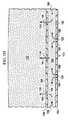
図1Cを参照すると、カプセル化脚部材106の一部の横断面が示されている。上述した通り、脚マニフォールド部材160の第1の側部164が第1の脚カプセル化部材168で覆われており、脚マニフォールド部材160の組織に面した第2の側部166は、この場合、非粘着ドレープ148の一部である第2の脚カプセル化部材170によって覆われているのを見ることができる。このように、本実施例では、穿孔116が非粘着ドレープ148の複数の穿孔150のいくつかであっても良い。この実施例では、脚マニフォールド部材160の周辺エッジ176も、第1の脚カプセル化部材168の一部で覆われている。周辺エッジ176は、第1の縦エッジ177と第2の縦エッジ179を具える。第1の脚カプセル化部材168は、第1の側部164と、周辺エッジ176を覆っており、非粘着ドレープ148の第1の面178の上に延在して、エクステンション180を形成している。エクステンション180は、溶接182によって第2の脚カプセル化部材170に連結されている。しかしながら、第1の脚カプセル化部材168は、溶接(例えば、超音波溶接又はRF溶接)、ボンディング、接着剤、セメント、その他の公知の技術を用いて第2の脚カプセル化部材170に連結できる。 Referring to FIG. 1C, a cross section of a portion of the encapsulating
図1Dと図2を再度参照すると、中央連結部材112は、穿孔118を有する第1の連結カプセル化部材186内にカプセル化された連結マニフォールド部材154を具える。第1の連結カプセル化部材186は、連結マニフォールド部材154の第1の側部188上に配置されている。第2の連結カプセル化部材192は、連結マニフォールド部材154の組織に面した第2の側部190上に配置されている。第2の連結カプセル化部材192には、穿孔120が形成されている。第1の連結カプセル化部材186は、図2に示すように、周辺ゾーン又はエッジ194を有する。同様に、第2の連結カプセル化部材192は、周辺エッジ194に並んだ周辺ゾーン又はエッジ(明確には示されていない)を有する。第1の連結カプセル化部材186の周辺エッジ194は、複数のカプセル化脚部材106内の流体を図1Dに矢印196で示すように、連結マニフォールド部材154に流すために、脚連結領域152を除いて、第2の連結カプセル化部材192の周辺エッジに連結されている。流体は、また、矢印198で示すように、穿孔120を通って流れることによって連結マニフォールド部材154内に直接入る。マニフォールド122は、第1の連結カプセル化部材186の近傍に配置されており、減圧がマニフォールド122に適用されると、矢印199で示すように、減圧が流体を連結マニフォールド部材154から穿孔118を通ってマニフォールド122へ流れる。流体は、減圧インターフェース128の方向へ流れ続け、このインターフェースを通って、減圧送達管130へと除去される。 Referring again to FIGS. 1D and 2, the
図1A−1D、及び図2を参照すると、動作中は、図に示すシステム100は、定寸に切ることによって、治療デバイス102の第1のサイジングによって使用することができる。複数のカプセル化脚部材106を有する非粘着ドレープ148は、体腔開口126を通って腹腔内に配置されており、腹部内容物に対して配分されている。これは、第1の結腸傍溝108又は第2の結腸傍溝110内または近傍に少なくとも一のカプセル化脚部材106を配置することを含む。治療デバイス102が一旦配置されると、マニフォールド122が第1の連結カプセル化部材186の第1の側部184に隣接して配置される。シーリング部材124は、体腔開口126の上に当てられて、例えば、腹腔103など、体腔開口126の上に空気式シールを提供する。 With reference to FIGS. 1A-1D and FIG. 2, in operation, the
シーリング部材124に加えて、体腔開口126を例えばステープルなどの機械的閉合手段によって、あるいは、減圧閉合システムを用いて、閉合または強化しても良い。シーリング部材124は、様々な方法で適用することができるが、一実施例によれば、シーリング部材124の接着層136上にある取り外し可能な裏打ち部材を取り外して、シーリング部材124を体腔開口126の周囲の患者の上皮134に配置する。次いで、コネクタ138などの減圧インターフェース128をシーリング部材124に取り付けて、減圧インターフェース128によって、シーリング部材124を介してマニフォールド122へ減圧が送達されるようにする。減圧送達管130は、減圧インターフェース128と外部減圧源132上の減圧ポート144に流体連結されている。 In addition to the sealing
外部減圧源132が始動して、これによって減圧送達管130へ減圧が提供され、減圧インターフェース128へ、また、マニフォールド122内へ減圧を送達する。マニフォールド122は、減圧を分配して連結マニフォールド部材154から穿孔118を介して流体を引き込む。連結マニフォールド部材154は、炎症を促進する刺激を含めて、穿孔120を介して腹腔103から流体を引き込んで、矢印196で示すように、複数のカプセル化した脚部材106から流体を引き込む。腹腔103からの流体は、第1の脚カプセル化部材168上の穿孔114と第2の脚カプセル化部材170上の穿孔116を介して複数のカプセル化脚部材106へ流れ、次いで、矢印172に示すように、複数のカプセル化部材106を介して連結マニフォールド部材154へ流れる。この流体は、次いで、マニフォールド122、減圧インターフェース128を通って、減圧送達管130へと流れる。 An external reduced
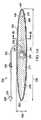
図3A及び3Bを参照すると、治療デバイス200の別の実施例が示されている。治療デバイス200は、最小侵襲性治療デバイスであり、ここでは、治療デバイス200が定寸に切られて、例えば、0.3cm乃至4.0cmの長さ範囲で、デバイス切開部を通って導入されるように構成されている。いくつかの場合、デバイス切開部は、4.0cm乃至8.0cmの長さあるいはそれ以上であっても良い。治療デバイス200は、ワンピース設計で形成して、治療デバイス200の配置と腹腔からの取り外しを容易にするようにしても良い。 With reference to FIGS. 3A and 3B, another embodiment of a
治療デバイス200は、カプセル化脚部材205として形成されており、第1の端部202と第2の端部204とを有する。カプセル化脚部材205の第1の端部202と第2の端部204とは、例えば結腸傍溝などの腹腔の引き締まった部分に配置するのに特に適している。治療デバイス200は、カプセル化エンベロープ208に封入されている脚マニフォールド部材206と共に形成されている。脚マニフォールド部材206は、マニフォールド122や脚マニフォールド160用のものなど、どのようなマニフォールド材であっても良い。脚マニフォールド部材206は適当な硬さがあり、カプセル化脚部材205の配置を容易にしている。 The
カプセル化エンベロープ208は、第1の脚カプセル化部材210と第2の脚カプセル化部材212で形成されている。各脚カプセル化部材210、212は周辺エッジ214を有している。第1の脚カプセル化210と第2の脚カプセル化部材212の周辺エッジ214は、限定することなく、溶接(例えば超音波溶接又はRF溶接)、ボンディング、接着剤、セメント、その他を含む何らかの技術を用いて連結される。本実施例の周辺エッジ214は、溶接216によって連結されている。脚カプセル化部材210及び212は、穿孔したフィルムあるいはカバー、または上記のシーリング部材124用の材料で形成することができる。 The
第1の脚カプセル化部材210と第2の脚カプセル化部材212の上に複数の穿孔218が形成されており、従って、カプセル化エンベロープ208の上に穿孔218が形成されている。連結インターフェース220又は減圧インターフェースは、カプセル化エンベロープ208に連結されており、脚マニフォールド部材206と流体連通されている。減圧送達管222は、連結インターフェース220に連結しても良い。減圧送達管222は、第1の端部224と第2の端部226を有する。第2の端部226にフィッティング228を配置して、外部減圧源(例えば、図1Aに示す外部減圧源132)に迅速に接続できるようにしても良い。減圧送達管222の第1の端部224は、連結インターフェース220に流体連結されている。管クランプ230を減圧送達管222に配置しても良い。 A plurality of
カプセル化脚部材205は、長さ(L)232と幅(W)234を有する。図3Aに示す治療デバイス200用には、アスペクト比(L/W)は、一実施例において、1.5乃至6.0の範囲である。一形状のアスペクト比は、その形状のより長い寸法に対するより短い寸法の比である。このことは、最も長い軸対最も短い軸、あるいは、二つの測定値によって特定される対称物体については、ロッドの長さと径といった、三次元形状の二つの特徴的な寸法に適用することができる。円環面のアスペクト比は、長軸R対短軸rの比である。図3Aに示す治療デバイス200などのほぼ平坦な脚部材については、アスペクト比が、L/W比である。 The encapsulated
圧力トランスデューサ238を、治療デバイス200内に設ける、あるいは代替的にデバイスに取り付けるようにしても良い。トランスデューサのリード240は、圧力トランスデューサ238に接続されており、脚マニフォールド部材206に沿って連結インターフェース220へ伸びていても良く、また、減圧送達管222内をまたはこれに沿って、トランスデューサのリード240が装置に接続されて圧力トランスデューサ238によって得た腹腔内の圧力表示を提供する、患者の外部ポイントへ伸びていても良い。 A
治療デバイス200の使用について述べる。治療デバイス200は、開腹した腹部を通って(図1A参照)または、患者の上皮を通って経皮的に(図1Aの上皮134参照)、展開させることができる。治療デバイス200の使用は、ここに述べるその他のデバイスと同様である。トロカールを用いたデバイス切開部を介するにしても、あるいは開腹した腹部アプリケーションを介するにしても、ヘルスケア提供者は、腹腔内に治療デバイス200を配置して、好ましくは、第1の端部202を腹腔内容物上に配置し、結腸傍溝近傍に配置し、同様に第2の端部204を腹腔内容物、好ましくは結腸傍溝上の位置に置く。減圧送達管222は、腹腔内から腹腔外のポイントへ伸びており、例えば、図1Aの外部減圧源132などの外部減圧源に連結されている。デバイス切開部は、(図1Aのシーリング部材124などの、シーリング部材によって)シールすることができる。減圧は、減圧送達管222を介して連結インターフェース220へ送達される。 The use of the
連結インターフェース220は、脚マニフォールド部材206に流体連結されており、そこへ減圧を送達する。しかして、流体が脚マニフォールド部材206へ引き込まれ、連結インターフェース220へ送達され、減圧送達管222へ送達される。減圧送達管222は、保存、廃棄、あるいは治療用に腹腔外の位置に流体を送達する。除去した流体は、腹水、サイトカイン、及び炎症を促進する刺激を含む腹腔からのその他の流体を含んでいる。この流体が腹腔から移動するので、炎症反応が抑制される。 The
治療デバイス200に接続されている圧力トランスデューサ238は、トランスデューサリード240を用いて、腹腔内の圧力を測定するデバイスに接続されている。腹腔内の圧力をモニタして、追加の治療デバイス200を展開させるべきか否か、あるいはその他の介入が必要か否かを決定する。治療デバイス200を用いた炎症を促進する刺激の除去と腹腔内の減圧治療は、0.5時間乃至40時間以上にわたる間(T)続けても良い。 A
ヘルスケア提供者が、治療デバイス200を用いた治療の必要がなくなったと決定すると、最小侵襲製治療デバイスである治療デバイス200は、デバイス切開部を通って取り除かれる。治療デバイス200は、減圧送達管222の上に力を加えることによって取り除かれる。治療デバイス200がデバイス切開部から取り除かれると、縫合、ボンディング、バンデージ、ステープルなどの公知の技術でデバイス切開部を閉合するか、あるいは自然治癒させる。図4に示す治療デバイス300の使用は、治療デバイス200の使用に類似しているが、単一デバイスでより大きな治療領域を提供している。 When the healthcare provider determines that treatment with the
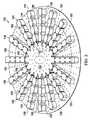
ここで図4を参照すると、治療デバイス300の別の実施例が示されている。治療デバイス300もまた、最小侵襲性治療デバイスであり、治療デバイス300を展開させて、例えば0.3cm乃至4.0cmの範囲の長さの、デバイス切開部を介して取り除かれる。治療デバイス300には、第1の脚マニフォールド部材302と第2の脚マニフォールド部材304が形成されている。第1の脚マニフォールド部材302と第2の脚マニフォールド部材304が交差して、中央連結部位305を形成している。第1の脚マニフォールド部材302と第2の脚マニフォールド部材304は、一体的なマニフォールド部材材料で(例えば、上述したマニフォールド122と連結して記載されているマニフォールド材料)形成しても良く、あるいは二つのマニフォールド材料をのり付などの技術によって、連結するようにしても良い。また、治療デバイス300は、ワンピース設計として、展開と取り外しを容易にしても良い。 Referring now to FIG. 4, another embodiment of a
第1及び第2の脚マニフォールド部材302と304は、カプセル化エンベロープ306の中にカプセル化されており、穿孔308が設けられている。カプセル化エンベロープ306は、図1Aにおけるシーリング部材124に関連して述べた材料などの、フィルム又はカバーでできている。第1の脚マニフォールド部材302と第2の脚マニフォールド部材304は交差して、様々なサイズの角度を形成している。治療デバイス300は、換言すれば、「X」形状をしている。図に示す実施例では、この角度は二つの鈍角310と二つの鋭角312を含む。カプセル化エンベロープ306内の第1の脚マニフォールド部材302と第2の脚マニフォールド部材304の端部は、腹腔内の複数の位置における流体の回収を容易にしている。 First and second
連結インターフェース314が、中央連結部位305に連結しており、第1の脚マニフォールド部材302及び第2の脚マニフォールド部材304に流体連結している。連結インターフェース314が中央連結部位305へ連結しており、減圧送達管320が連結インターフェース314へ連結しているため、初期に減圧送達管320に力を加えることによって、例えば、長さ0.3cm乃至4.0cmの範囲のデバイス切開部を介して治療デバイス300を取り除くことができる。 A
カプセル化エンベロープ306は、第1のカプセル化部材316と第2の脚カプセル化部材(第1及び第2の脚マニフォールド部材302、304の反対側の)で形成することができる。第1のカプセル化部材316と第2の脚カプセル化部材は、第1の脚マニフォールド部材302と第2の脚マニフォールド部材304を取り囲んで覆っている外側層を形成している。第1のカプセル化部材316と第2の脚カプセル化部材は、上述したような公知の技術を用いて、周辺部分318、または周辺エッジにおいて連結されている。図に示す実施例では、RF溶接322を用いて、第1のカプセル化部材316の周辺部分318と第2のカプセル化部材とを連結している。減圧送達管320は、連結インターフェース314及び外部減圧源(例えば、図1Aに示す外部減圧源132)に流体連結されている。 The
図5A及び5Bを参照すると、治療デバイス400の別の実施例が示されている。治療デバイス400は、複数のカプセル化脚部材402を具える。各カプセル化脚部材402は、第1の端部404と第2の端部406を具える。各カプセル化脚部材402は、結腸傍溝内あるいは近傍、肝臓の後ろなど、腹腔内の異なる位置に配置することができる。各カプセル化脚部材402は、穿孔410が形成された外部層408を有する。この外側層408は、脚マニフォールド部材416を具える内部スペース414を規定するカプセル化エンベロープ412を形成している。この外側層408は、シーリング部材124に関連して述べられたような、フィルム又はカバーで形成されても良い。 Referring to FIGS. 5A and 5B, another embodiment of a
各カプセル化脚部材402の第1の端部404は、連結インターフェース418である。複数の連結管420は、連結インターフェース418に並んで連結されている。各連結管420は、第1の端部422と第2の端部424を有する。連結管420の第2の端部424は、関連するカプセル402の連結インターフェース418に連結されている。第1の連結管420の第1の端部422はインターフェース管426に連結されている。インターフェース管426は、第1の端部428と第2の端部430を有する。各インターフェース管426の第2の端部430は、連結管420の一方の第1の端部422に連結している。コネクタ438を用いて、各連結管420の第1の端部422をインターフェース管426の第2の端部430に連結している。インターフェース管426の第1の端部428は、減圧送達管(図示せず)に、又は、外部減圧源に直接連結されていても良い。図5Aに示す実施例では、複数のカプセル化脚部材402が、第1のカプセル化脚部材432と第2のカプセル化脚部材434を具える。任意の数の追加のカプセル化脚部材を特定の必要に応じて加えることは自明である。 The
治療デバイス400の使用について述べる。治療デバイス400は、開腹部を介してあるいはトロカールを用いて経皮的に導入することができる。外科医は、デバイス切開部を作り、連結管420に沿った第1のカプセル化脚部材432などの単一のカプセル化脚部材402を患者の腹腔内に挿入する。外科医は、その他のデバイス切開部を作って、適当と考えられる関連する連結管420と共にその他のカプセル化脚部材402を挿入することができる。 The use of the
所望の数のカプセル化脚部材402をデバイス切開部を介して延在している連結管420と共に腹腔内に配置したら、連結部材420の第1の端部422をコネクタ438に連結することができる。コネクタ438は、インターフェース管426に連結されている。インターフェース管426は、図1Aに示す外部減圧源132などの外部減圧源に連結することができる。次いで、一またはそれ以上の治療デバイス400を用いた治療を開始する。 Once the desired number of encapsulated
治療デバイス400を用いた治療は、所望の期間(T)の間行われる。治療が終了して治療デバイス400の取り外しを行う際に、コネクタ438を取り外して、複数の連結管420は患者から初期に伸びているままにしておく。次いで各連結管420を引っ張って、関連するカプセル化脚部材402を対応するデバイス切開部から取り外す。治療デバイス400では、装着又は取り外し用の開腹部を必要とすることなく、任意の数のカプセル化脚部材402を使用することができることを認識すべきである。 Treatment using the
腹腔のコンテキストにおいて最小侵襲技術を用いて展開できる図に示すシステム及びデバイスに関しては、回復術に比較してより早く介入が生じる。このことは、最小侵襲治療デバイスが開腹の場合のような30cmあるいはこれより長い切開を行わないので、外科医が開腹するよりも非常に早い段階でのマネージメントにおいて最小侵襲治療デバイスの使用を行うことができるため、現実に起こりうる。外科医に受傷後早期の段階で、一又それ以上の最小侵襲治療デバイスでの介入の機会を提供することによって、炎症性刺激を除圧まで持続させる徐々に有害な効果に腹部内臓を露出させる時間を実質的に低減させ、従って、実際に、重症度と疾病の程度を低減する。 For the systems and devices shown in the figure that can be deployed using minimally invasive techniques in the context of the abdominal cavity, intervention occurs earlier compared to recovery procedures. This is because the minimally invasive treatment device does not make an incision 30 cm or longer as in the case of a laparotomy, so the use of the minimally invasive treatment device in management at an earlier stage than the surgeon opens. It can happen because it can. Time to expose the abdominal viscera to the gradual detrimental effects that sustain inflammatory stimuli until decompression by providing the surgeon with the opportunity to intervene with one or more minimally invasive treatment devices early in the wound Is substantially reduced, and thus actually reduces the severity and degree of illness.
図に示す実施例と方法の利点は、非限定的な実施例のコンテキストにおいて開示されているが、様々な変更、交換、置換、及び変形を、特許請求の範囲によって規定された発明の範囲から外れることなく行うことができると解すべきである。いずれかの実施例に関連して述べた特徴は、その他の実施例にも適用することができる。
While the advantages of the illustrated embodiments and methods are disclosed in the context of non-limiting embodiments, various changes, substitutions, substitutions, and variations are within the scope of the invention as defined by the claims. It should be understood that this can be done without losing. Features described in connection with any embodiment can be applied to other embodiments.
Claims (24)
Translated fromJapanese前記組織部位近傍に減圧治療デバイスを展開するステップと;
外部減圧源を前記減圧治療デバイスに流体連結して、前記内部組織部位近傍に減圧を提供するステップと;
前記外部減圧源から前記減圧治療デバイスに減圧を提供するステップと;
前記内部組織部位における炎症を促進する環境を治療して、炎症反応を抑制するステップと;
を具えることを特徴とする炎症反応を抑制する方法。In a method for suppressing an inflammatory response in a patient's internal tissue site:
Deploying a reduced pressure treatment device in the vicinity of the tissue site;
Fluidly connecting an external reduced pressure source to the reduced pressure treatment device to provide reduced pressure near the internal tissue site;
Providing reduced pressure from the external reduced pressure source to the reduced pressure treatment device;
Treating an environment that promotes inflammation at the internal tissue site to inhibit an inflammatory response;
A method for suppressing an inflammatory reaction, comprising:
前記減圧治療デバイスが、最小侵襲治療デバイスを具え;
前記外部減圧源を減圧治療デバイスに流体連結するステップが、減圧送達管を前記最小侵襲治療デバイスと、前記外部減圧源とに流体連結するステップを具え;
更に、前記最小侵襲治療デバイスを、デバイス切開部を介して前記腹腔から取り除くステップと;
を具えることを特徴とする方法。The method for suppressing an inflammatory reaction according to claim 1,
The reduced pressure treatment device comprises a minimally invasive treatment device;
Fluidly coupling the external vacuum source to a vacuum therapy device comprises fluidly coupling a vacuum delivery tube to the minimally invasive therapy device and the external vacuum source;
Removing the minimally invasive treatment device from the abdominal cavity via a device incision;
A method characterized by comprising.
複数のカプセル化脚部材であって、各カプセル化脚部材が脚マニフォールド部材を伴う内側部分を有しており、当該内側部分に流体が流れるように操作可能な穿孔が形成されている複数のカプセル化部材と;
中央連結部材であって、当該中央連結部材が連結マニフォールド部材を有しており、各脚マニフォールド部材が前記連結マニフォールド部材と流体連通しており、前記中央連結部材が第1の側部と組織に面した第2の側部とを具える、中央連結部材と;
を具えることを特徴とする方法。2. The method of suppressing an inflammatory response according to claim 1, wherein the reduced pressure treatment device:
A plurality of encapsulated leg members, each encapsulated leg member having an inner portion with a leg manifold member, wherein the inner portion is formed with perforations operable to allow fluid to flow A chemical member;
A central connecting member, wherein the central connecting member has a connecting manifold member, each leg manifold member is in fluid communication with the connecting manifold member, and the central connecting member is in communication with the first side and the tissue. A central coupling member comprising a second side facing;
A method characterized by comprising.
第1の脚カプセル化部材と;
穿孔が形成された第2の脚カプセル化部材と;
を具え、
前記脚マニフォールド部材が第1の側部と、組織に面した第2の側部と、第1の横方向エッジと、第2の横方向エッジとを具え;
前記第1の脚カプセル化部材が、前記脚マニフォールド部材の第1の側部近傍に配置されており、前記第2の脚カプセル化部材が、前記脚マニフォールド部材の前記組織に面した第2の側部近傍に配置されており、前記第1の脚カプセル化部材と前記第2の脚カプセル化部材が、前記脚マニフォールド部材の第1の横方向エッジと前記第2の横方向エッジ近傍で連結されている;
ことを特徴とする方法。10. The method of suppressing an inflammatory response according to claim 9, wherein each encapsulated leg member of the plurality of encapsulated leg members:
A first leg encapsulation member;
A second leg encapsulating member formed with perforations;
With
The leg manifold member comprises a first side, a second side facing the tissue, a first lateral edge, and a second lateral edge;
The first leg encapsulation member is disposed near a first side of the leg manifold member, and the second leg encapsulation member is a second facing the tissue of the leg manifold member. Disposed near a side and wherein the first leg encapsulation member and the second leg encapsulation member are coupled in the vicinity of the first lateral edge and the second lateral edge of the leg manifold member. Has been;
A method characterized by that.
カプセル化脚部材であって、当該カプセル化脚部材が脚マニフォールド部材と、穿孔を形成して前記脚マニフォールド部材を封入するカプセル化エンベロープを具え、前記カプセル化脚部材が3.0より大きいアスペクト比を有する、カプセル化脚部材と;
前記カプセル化脚部材に連結され、前記脚マニフォールド部材に流体連結された連結インターフェースと;
を具えることを特徴とする方法。2. The method of suppressing an inflammatory response according to claim 1, wherein the reduced pressure treatment device:
An encapsulated leg member, the encapsulated leg member comprising a leg manifold member and an encapsulating envelope forming a perforation to enclose the leg manifold member, wherein the encapsulated leg member has an aspect ratio greater than 3.0 An encapsulated leg member;
A coupling interface coupled to the encapsulating leg member and fluidly coupled to the leg manifold member;
A method characterized by comprising.
カプセル化脚部材であって、当該カプセル化脚部材が脚マニフォールド部材と、穿孔を形成して前記脚マニフォールド部材を封入するカプセル化エンベロープを具え、前記カプセル化脚部材が4.0より大きいアスペクト比を有する、カプセル化脚部材と;
前記カプセル化脚部材に連結され、前記脚マニフォールド部材に流体連結された連結インターフェースと;
を具えることを特徴とする方法。2. The method of suppressing an inflammatory response according to claim 1, wherein the reduced pressure treatment device:
An encapsulated leg member, the encapsulated leg member comprising a leg manifold member and an encapsulating envelope forming a perforation to enclose the leg manifold member, wherein the encapsulated leg member has an aspect ratio greater than 4.0 An encapsulated leg member;
A coupling interface coupled to the encapsulating leg member and fluidly coupled to the leg manifold member;
A method characterized by comprising.
カプセル化脚部材であって、当該カプセル化脚部材が脚マニフォールド部材と、穿孔を形成して前記脚マニフォールド部材を封入するカプセル化エンベロープを具え、前記カプセル化脚部材が5.0より大きいアスペクト比を有する、カプセル化脚部材と;
前記カプセル化脚部材に連結され、前記脚マニフォールド部材に流体連結された連結インターフェースと;
を具えることを特徴とする方法。2. The method of suppressing an inflammatory response according to claim 1, wherein the reduced pressure treatment device:
An encapsulated leg member, the encapsulated leg member comprising a leg manifold member and an encapsulating envelope forming a perforation to enclose the leg manifold member, wherein the encapsulated leg member has an aspect ratio greater than 5.0 An encapsulated leg member;
A coupling interface coupled to the encapsulating leg member and fluidly coupled to the leg manifold member;
A method characterized by comprising.
第1の脚マニフォールド部材と第2の脚マニフォールド部材であって、前記第1の脚マニフォールド部材と前記第2の脚マニフォールド部材が交差して中央連結部位を形成している、第1の脚マニフォールド部材と第2の脚マニフォールド部材と;
前記第1の脚マニフォールド部材と、前記第2の脚マニフォールド部材と、前記中央連結部位の上に外部層を形成するカプセル化エンベロープであって、前記カプセル化エンベロープに穿孔が形成されて内側部分に流体が流れるようにしたカプセル化エンベロープと;
を具えることを特徴とする方法。2. The method of suppressing an inflammatory response according to claim 1, wherein the reduced pressure treatment device:
A first leg manifold member and a second leg manifold member, wherein the first leg manifold member and the second leg manifold member intersect to form a central coupling site. A member and a second leg manifold member;
An encapsulating envelope forming an outer layer on the first leg manifold member, the second leg manifold member, and the central coupling site, wherein the encapsulating envelope is perforated to form an inner portion; An encapsulated envelope that allows fluid to flow;
A method characterized by comprising.
複数のカプセル化脚部材であって、各々が脚マニフォールド部材を伴う内側部分を有し、当該内側部分に流体が流れるように操作可能な穿孔が形成されており、各々が第1及び第2の端部を有し、当該複数のカプセル化脚部材の各々が前記第1の端部に連結インターフェースを具える、複数のカプセル化脚部材と;
複数の連結管であって、各々が第1の端部と第2の端部を有する複数の連結管と;
第1及び第2の端部を有するインターフェース管と;
を具え、
前記複数の連結管の各々の第1の端部が前記インターフェース管の第2の端部に連結されており;
前記複数の連結管の各々の第2の端部が前記連結インターフェースにおいて前記複数のカプセル化脚部材に連結されている;
ことを特徴とする方法。2. The method of suppressing an inflammatory response according to claim 1, wherein the reduced pressure treatment device:
A plurality of encapsulated leg members, each having an inner portion with a leg manifold member, wherein the inner portion is formed with perforations operable to allow fluid flow, each of the first and second A plurality of encapsulated leg members having ends, each of the plurality of encapsulated leg members comprising a coupling interface at the first end;
A plurality of connecting pipes, each having a first end and a second end;
An interface tube having first and second ends;
With
A first end of each of the plurality of connecting tubes is connected to a second end of the interface tube;
A second end of each of the plurality of connecting tubes is connected to the plurality of encapsulating leg members at the connection interface;
A method characterized by that.
内部組織部位近傍に展開する減圧治療デバイスであって、最小侵襲治療デバイスを具える減圧治療デバイスと;
患者の上皮の一部に配置して前記内部組織部位の上に空気式シールを形成するように動作可能なシーリング部材と;
減圧を供給する外部減圧源と;
前記外部減圧源と連結インターフェースを流体連結する減圧送達管と;
を具え、
前記減圧源、減圧送達管、及び減圧治療デバイスが、前記外部減圧源から前記減圧治療デバイスへ減圧を提供し、炎症を促進する刺激を緩和するように動作可能であること、を特徴とするシステム。In a system that suppresses inflammatory responses in a patient's internal tissue site:
A reduced pressure treatment device deployed near an internal tissue site, comprising a minimally invasive treatment device;
A sealing member disposed on a portion of the patient's epithelium and operable to form a pneumatic seal over the internal tissue site;
An external reduced pressure source supplying reduced pressure;
A reduced pressure delivery tube fluidly connecting a connection interface with the external reduced pressure source;
With
The reduced pressure source, reduced pressure delivery tube, and reduced pressure treatment device are operable to provide reduced pressure from the external reduced pressure source to the reduced pressure treatment device to mitigate stimuli that promote inflammation. .
カプセル化脚部材であって、当該カプセル化脚部材が脚マニフォールド部材と、穿孔を形成して前記脚マニフォールド部材を封入するカプセル化エンベロープを具え、前記カプセル化脚部材が3.0より大きいアスペクト比を有する、カプセル化脚部材と;
前記カプセル化脚部材に連結され、前記脚マニフォールド部材に流体連結されている連結インターフェースと;
を具えることを特徴とするシステム。19. The system for suppressing an inflammatory response according to claim 18, wherein the reduced pressure treatment device:
An encapsulated leg member, the encapsulated leg member comprising a leg manifold member and an encapsulating envelope forming a perforation to enclose the leg manifold member, wherein the encapsulated leg member has an aspect ratio greater than 3.0 An encapsulated leg member;
A coupling interface coupled to the encapsulating leg member and fluidly coupled to the leg manifold member;
A system characterized by comprising.
カプセル化脚部材であって、当該カプセル化脚部材が脚マニフォールド部材と、穿孔を形成して前記脚マニフォールド部材を封入するカプセル化エンベロープを具え、前記カプセル化脚部材が4.0より大きいアスペクト比を有する、カプセル化脚部材と;
前記カプセル化脚部材に連結され、前記脚マニフォールド部材に流体連結されている連結インターフェースと;
を具えることを特徴とするシステム。19. The system for suppressing an inflammatory response according to claim 18, wherein the reduced pressure treatment device:
An encapsulated leg member, the encapsulated leg member comprising a leg manifold member and an encapsulating envelope forming a perforation to enclose the leg manifold member, wherein the encapsulated leg member has an aspect ratio greater than 4.0 An encapsulated leg member;
A coupling interface coupled to the encapsulating leg member and fluidly coupled to the leg manifold member;
A system characterized by comprising.
カプセル化脚部材であって、当該カプセル化脚部材が脚マニフォールド部材と、穿孔を形成して前記脚マニフォールド部材を封入するカプセル化エンベロープを具え、前記カプセル化脚部材が5.0より大きいアスペクト比を有する、カプセル化脚部材と;
前記カプセル化脚部材に連結され、前記脚マニフォールド部材に流体連結されている連結インターフェースと;
を具えることを特徴とするシステム。19. The system for suppressing an inflammatory response according to claim 18, wherein the reduced pressure treatment device:
An encapsulated leg member, the encapsulated leg member comprising a leg manifold member and an encapsulating envelope forming a perforation to enclose the leg manifold member, wherein the encapsulated leg member has an aspect ratio greater than 5.0 An encapsulated leg member;
A coupling interface coupled to the encapsulating leg member and fluidly coupled to the leg manifold member;
A system characterized by comprising.
第1の脚マニフォールド部材と第2の脚マニフォールド部材であって、前記第1の脚マニフォールド部材と第2の脚マニフォールド部材が交差して中央連結部位を形成する、第1の脚マニフォールド部材と第2の脚マニフォールド部材と;
前記第1の脚マニフォールド部材と、前記第2の脚マニフォールド部材と、前記中央連結部位との上に外部層を形成するカプセル化エンベロープであって、前記カプセル化エンベロープに穿孔が形成されて内側部分に流体が流れるようにしたカプセル化エンベロープと;
を具えることを特徴とするシステム。19. The system for suppressing an inflammatory response according to claim 18, wherein the reduced pressure treatment device:
A first leg manifold member and a second leg manifold member, wherein the first leg manifold member and the second leg manifold member intersect to form a central coupling site; Two leg manifold members;
An encapsulating envelope forming an outer layer over the first leg manifold member, the second leg manifold member, and the central connection site, wherein the encapsulating envelope is perforated to form an inner portion An encapsulated envelope that allows fluid to flow through;
A system characterized by comprising.
複数のカプセル化脚部材であって、各々が脚マニフォールド部材を有する内側部分を有し、当該内側部分に流体が流れるように動作可能な穿孔が形成されており、各々が第1の端部と第2の端部を有し、当該複数のカプセル化脚部材の各々が前記第1の端部に連結インターフェースを具える、複数のカプセル化脚部材と;
複数の連結管であって、各々が第1の端部と第2の端部を有する連結管と;
第1の端部と第2の端部を有するインターフェース管と;
を具え、
前記複数の連結管の各々の第1の端部が前記インターフェース管の第2の端部に連結されており;
前記複数の連結管の各々の第2の端部が前記連結インターフェースにおいて前記複数のカプセル化脚部材に連結されている;
ことを特徴とするシステム。
19. The system for suppressing an inflammatory response according to claim 18, wherein the reduced pressure treatment device:
A plurality of encapsulated leg members, each having an inner portion having a leg manifold member, wherein the inner portion is formed with perforations operable to allow fluid to flow, each having a first end and A plurality of encapsulated leg members having a second end, each of the plurality of encapsulated leg members comprising a coupling interface at the first end;
A plurality of connecting tubes, each having a first end and a second end;
An interface tube having a first end and a second end;
With
A first end of each of the plurality of connecting tubes is connected to a second end of the interface tube;
A second end of each of the plurality of connecting tubes is connected to the plurality of encapsulating leg members at the connection interface;
A system characterized by that.
Applications Claiming Priority (3)
| Application Number | Priority Date | Filing Date | Title |
|---|---|---|---|
| US9803008P | 2008-09-18 | 2008-09-18 | |
| US61/098,030 | 2008-09-18 | ||
| PCT/US2009/044235WO2010033271A1 (en) | 2008-09-18 | 2009-05-15 | Systems and methods for controlling inflammatory response |
Publications (2)
| Publication Number | Publication Date |
|---|---|
| JP2012502731Atrue JP2012502731A (en) | 2012-02-02 |
| JP5337248B2 JP5337248B2 (en) | 2013-11-06 |
Family
ID=40999942
Family Applications (2)
| Application Number | Title | Priority Date | Filing Date |
|---|---|---|---|
| JP2011527843AActiveJP5337248B2 (en) | 2008-09-18 | 2009-05-15 | Inflammatory response suppression system and method |
| JP2011527844AExpired - Fee RelatedJP5318957B2 (en) | 2008-09-18 | 2009-05-15 | Therapeutic delivery system and method |
Family Applications After (1)
| Application Number | Title | Priority Date | Filing Date |
|---|---|---|---|
| JP2011527844AExpired - Fee RelatedJP5318957B2 (en) | 2008-09-18 | 2009-05-15 | Therapeutic delivery system and method |
Country Status (12)
| Country | Link |
|---|---|
| US (7) | US8246606B2 (en) |
| EP (4) | EP3536358A1 (en) |
| JP (2) | JP5337248B2 (en) |
| KR (2) | KR20110058872A (en) |
| CN (4) | CN102143772B (en) |
| AU (2) | AU2009293592B8 (en) |
| BR (2) | BRPI0913550A2 (en) |
| CA (2) | CA2734961C (en) |
| MX (2) | MX2011002861A (en) |
| RU (2) | RU2011107112A (en) |
| TW (2) | TW201019976A (en) |
| WO (2) | WO2010033271A1 (en) |
Families Citing this family (138)
| Publication number | Priority date | Publication date | Assignee | Title |
|---|---|---|---|---|
| GB0224986D0 (en) | 2002-10-28 | 2002-12-04 | Smith & Nephew | Apparatus |
| GB0325126D0 (en) | 2003-10-28 | 2003-12-03 | Smith & Nephew | Apparatus with heat |
| GB0325120D0 (en)* | 2003-10-28 | 2003-12-03 | Smith & Nephew | Apparatus with actives |
| US11298453B2 (en) | 2003-10-28 | 2022-04-12 | Smith & Nephew Plc | Apparatus and method for wound cleansing with actives |
| US8758313B2 (en)* | 2003-10-28 | 2014-06-24 | Smith & Nephew Plc | Apparatus and method for wound cleansing with actives |
| US7909805B2 (en) | 2004-04-05 | 2011-03-22 | Bluesky Medical Group Incorporated | Flexible reduced pressure treatment appliance |
| US10058642B2 (en) | 2004-04-05 | 2018-08-28 | Bluesky Medical Group Incorporated | Reduced pressure treatment system |
| GB0409446D0 (en) | 2004-04-28 | 2004-06-02 | Smith & Nephew | Apparatus |
| EP2214612B1 (en) | 2007-11-21 | 2019-05-01 | Smith & Nephew PLC | Wound dressing |
| ES2715605T3 (en) | 2007-11-21 | 2019-06-05 | Smith & Nephew | Wound dressing |
| WO2009067711A2 (en) | 2007-11-21 | 2009-05-28 | T.J. Smith & Nephew, Limited | Suction device and dressing |
| GB0722820D0 (en) | 2007-11-21 | 2008-01-02 | Smith & Nephew | Vacuum assisted wound dressing |
| GB0723875D0 (en) | 2007-12-06 | 2008-01-16 | Smith & Nephew | Wound management |
| US20130096518A1 (en) | 2007-12-06 | 2013-04-18 | Smith & Nephew Plc | Wound filling apparatuses and methods |
| US11253399B2 (en) | 2007-12-06 | 2022-02-22 | Smith & Nephew Plc | Wound filling apparatuses and methods |
| GB0723872D0 (en) | 2007-12-06 | 2008-01-16 | Smith & Nephew | Apparatus for topical negative pressure therapy |
| US8298200B2 (en) | 2009-06-01 | 2012-10-30 | Tyco Healthcare Group Lp | System for providing continual drainage in negative pressure wound therapy |
| US9033942B2 (en) | 2008-03-07 | 2015-05-19 | Smith & Nephew, Inc. | Wound dressing port and associated wound dressing |
| GB0804654D0 (en) | 2008-03-13 | 2008-04-16 | Smith & Nephew | Vacuum closure device |
| ES2658263T3 (en) | 2008-08-08 | 2018-03-09 | Smith & Nephew, Inc. | Continuous fiber wound dressing |
| AU2016277595B2 (en)* | 2008-10-29 | 2018-10-18 | Solventum Intellectual Properties Company | Open-cavity, reduced-pressure treatment devices and systems |
| WO2010051071A1 (en) | 2008-10-29 | 2010-05-06 | Kci Licensing, Inc. | Reduced-pressure, wound-closure and treatment systems and methods |
| TW201021867A (en)* | 2008-12-12 | 2010-06-16 | Ind Tech Res Inst | Fluid processing system and collecting device thereof |
| US8162907B2 (en) | 2009-01-20 | 2012-04-24 | Tyco Healthcare Group Lp | Method and apparatus for bridging from a dressing in negative pressure wound therapy |
| GB0902368D0 (en) | 2009-02-13 | 2009-04-01 | Smith & Nephew | Wound packing |
| US20100324516A1 (en) | 2009-06-18 | 2010-12-23 | Tyco Healthcare Group Lp | Apparatus for Vacuum Bridging and/or Exudate Collection |
| US20110054420A1 (en)* | 2009-08-27 | 2011-03-03 | Christopher Brian Locke | Reduced-pressure wound dressings and systems for re-epithelialization and granulation |
| AU2010341491B2 (en) | 2009-12-22 | 2015-05-14 | Smith & Nephew, Inc. | Apparatuses and methods for negative pressure wound therapy |
| JP6013921B2 (en) | 2010-02-23 | 2016-10-25 | エル−ヴイエイディー テクノロジー インコーポレイティッドL−Vad Technology,Inc. | Vacuum-assisted transcutaneous device |
| US8791315B2 (en) | 2010-02-26 | 2014-07-29 | Smith & Nephew, Inc. | Systems and methods for using negative pressure wound therapy to manage open abdominal wounds |
| US8469935B2 (en) | 2010-03-11 | 2013-06-25 | Kci Licensing, Inc. | Abdominal treatment systems, delivery devices, and methods |
| US8721606B2 (en) | 2010-03-11 | 2014-05-13 | Kci Licensing, Inc. | Dressings, systems, and methods for treating a tissue site |
| US20110257611A1 (en)* | 2010-04-16 | 2011-10-20 | Kci Licensing, Inc. | Systems, apparatuses, and methods for sizing a subcutaneous, reduced-pressure treatment device |
| USRE48117E1 (en) | 2010-05-07 | 2020-07-28 | Smith & Nephew, Inc. | Apparatuses and methods for negative pressure wound therapy |
| USD692565S1 (en) | 2010-06-03 | 2013-10-29 | Smith & Nephew, Inc. | Organ protection layer |
| US9526920B2 (en) | 2010-10-12 | 2016-12-27 | Smith & Nephew, Inc. | Medical device |
| CA140189S (en) | 2010-10-15 | 2011-11-07 | Smith & Nephew | Medical dressing |
| CA140188S (en) | 2010-10-15 | 2011-11-07 | Smith & Nephew | Medical dressing |
| DE102010052336A1 (en) | 2010-11-25 | 2012-05-31 | Paul Hartmann Ag | Wound dressing for the negative pressure therapy |
| USD714433S1 (en) | 2010-12-22 | 2014-09-30 | Smith & Nephew, Inc. | Suction adapter |
| RU2016111981A (en) | 2010-12-22 | 2018-11-27 | Смит Энд Нефью, Инк. | DEVICE AND METHOD FOR TREATING RAS WITH NEGATIVE PRESSURE |
| US9421132B2 (en) | 2011-02-04 | 2016-08-23 | University Of Massachusetts | Negative pressure wound closure device |
| ES2571402T3 (en)* | 2011-04-18 | 2016-05-25 | Rigshospitalet Copenhagen Univ Hospital | Enhanced wound care product |
| CN107252383A (en) | 2011-07-14 | 2017-10-17 | 史密夫及内修公开有限公司 | Wound dressing and treatment method |
| DE102011082347A1 (en) | 2011-09-08 | 2013-03-14 | Paul Hartmann Ag | Wound dressing for use in the vacuum treatment of wounds |
| EP2626049B1 (en) | 2012-02-11 | 2018-07-25 | Paul Hartmann AG | Wound treatment device |
| JP6250571B2 (en) | 2012-03-12 | 2017-12-20 | スミス アンド ネフュー ピーエルシーSmith & Nephew Public Limited Company | Pressure reducing apparatus and method |
| AU346291S (en) | 2012-05-15 | 2013-01-09 | Smith & Nephew | Medical dressing |
| EP2852333B1 (en) | 2012-05-22 | 2021-12-15 | Smith & Nephew plc | Apparatuses for wound therapy |
| EP2852419B1 (en) | 2012-05-22 | 2019-11-20 | Smith & Nephew plc | Wound closure device |
| JP6400570B2 (en) | 2012-05-23 | 2018-10-10 | スミス アンド ネフュー ピーエルシーSmith & Nephew Public Limited Company | Apparatus and method for local negative pressure closure therapy |
| AU2013264937B2 (en) | 2012-05-24 | 2018-04-19 | Smith & Nephew Inc. | Devices and methods for treating and closing wounds with negative pressure |
| MX369689B (en) | 2012-07-16 | 2019-11-19 | Smith & Nephew Inc | Negative pressure wound closure device. |
| CN108186200B (en) | 2012-08-01 | 2021-08-10 | 史密夫及内修公开有限公司 | Wound dressing |
| WO2014020440A1 (en) | 2012-08-01 | 2014-02-06 | Smith & Nephew Plc | Wound dressing |
| US9623159B2 (en) | 2012-08-03 | 2017-04-18 | Kci Licensing, Inc. | Interfaces, systems, and methods for use in reduced pressure tissue treatment |
| US9662427B2 (en)* | 2012-08-13 | 2017-05-30 | Kci Licensing, Inc. | Intelligent therapy system with evaporation management |
| EP2928515B1 (en)* | 2012-12-06 | 2018-07-18 | IC Surgical, Inc. | Adaptable wound drainage system |
| US10124098B2 (en) | 2013-03-13 | 2018-11-13 | Smith & Nephew, Inc. | Negative pressure wound closure device and systems and methods of use in treating wounds with negative pressure |
| US9737649B2 (en) | 2013-03-14 | 2017-08-22 | Smith & Nephew, Inc. | Systems and methods for applying reduced pressure therapy |
| JP2016517318A (en) | 2013-03-14 | 2016-06-16 | スミス アンド ネフュー インコーポレーテッド | System and method for administering decompression therapy |
| BR112015021123A2 (en) | 2013-03-14 | 2017-07-18 | Smith & Nephew | compressible wound fillers and systems and methods for use in treating negative pressure injuries |
| US10010658B2 (en) | 2013-05-10 | 2018-07-03 | Smith & Nephew Plc | Fluidic connector for irrigation and aspiration of wounds |
| CA2920766A1 (en)* | 2013-08-07 | 2015-02-12 | Plurogen Therapeutics, Inc. | Delivery of medicants under continuous negative pressure dressing |
| WO2015023515A1 (en) | 2013-08-13 | 2015-02-19 | Smith & Nephew, Inc. | Systems and methods for applying reduced pressure therapy |
| CN106170275B (en) | 2013-10-21 | 2021-05-07 | 史密夫和内修有限公司 | Negative pressure wound closure device |
| CA3179001A1 (en) | 2014-07-31 | 2016-02-04 | Smith & Nephew, Inc. | Systems and methods for applying reduced pressure therapy |
| US12133789B2 (en) | 2014-07-31 | 2024-11-05 | Smith & Nephew, Inc. | Reduced pressure therapy apparatus construction and control |
| CA2972701A1 (en) | 2014-12-30 | 2016-07-07 | Smith & Nephew, Inc. | Systems and methods for applying reduced pressure therapy |
| EP3240587B1 (en) | 2014-12-30 | 2020-05-27 | Smith & Nephew, Inc | Systems for applying reduced pressure therapy |
| EP3441051B1 (en)* | 2015-01-14 | 2021-07-21 | 3M Innovative Properties Company | Closed abdominal manifold dressing |
| EP3744359A1 (en)* | 2015-02-02 | 2020-12-02 | 3M Innovative Properties Company | Customizable closed tissue site dressing for improved postoperative removal |
| DK3288508T3 (en) | 2015-04-27 | 2020-03-09 | Smith & Nephew | REDUCED PRESSURE DEVICES |
| AU2016254119A1 (en) | 2015-04-29 | 2017-10-05 | Smith & Nephew Inc. | Negative pressure wound closure device |
| US10076594B2 (en) | 2015-05-18 | 2018-09-18 | Smith & Nephew Plc | Fluidic connector for negative pressure wound therapy |
| CA2995686C (en)* | 2015-07-27 | 2022-12-13 | Noleus Technologies Inc. | Apparatuses and methods for improving post-operative recovery from surgery |
| US11315681B2 (en) | 2015-10-07 | 2022-04-26 | Smith & Nephew, Inc. | Reduced pressure therapy device operation and authorization monitoring |
| US11471586B2 (en) | 2015-12-15 | 2022-10-18 | University Of Massachusetts | Negative pressure wound closure devices and methods |
| WO2017132144A1 (en)* | 2016-01-28 | 2017-08-03 | Kci Licensing, Inc. | Sequential collapse waveform dressing |
| EP3426206B1 (en) | 2016-03-07 | 2023-05-10 | Smith & Nephew plc | Wound treatment apparatuses and methods with negative pressure source integrated into wound dressing |
| AU2017243601A1 (en) | 2016-03-30 | 2018-11-22 | Acib Gmbh | Detecting microbial infection in wounds |
| CA3022184A1 (en) | 2016-04-26 | 2017-11-02 | Smith & Nephew Plc | Wound dressings and methods of use with integrated negative pressure source having a fluid ingress inhibition component |
| CA3038206A1 (en) | 2016-05-03 | 2017-11-09 | Smith & Nephew Plc | Optimizing power transfer to negative pressure sources in negative pressure therapy systems |
| US11096831B2 (en) | 2016-05-03 | 2021-08-24 | Smith & Nephew Plc | Negative pressure wound therapy device activation and control |
| WO2017191158A1 (en) | 2016-05-03 | 2017-11-09 | Smith & Nephew Plc | Systems and methods for driving negative pressure sources in negative pressure therapy systems |
| CN109069713A (en) | 2016-05-13 | 2018-12-21 | 史密夫和内修有限公司 | Automatic wound in negative pressure wound treating system couples detection |
| WO2018037075A1 (en) | 2016-08-25 | 2018-03-01 | Smith & Nephew Plc | Absorbent negative pressure wound therapy dressing |
| JP7038701B2 (en) | 2016-08-30 | 2022-03-18 | スミス アンド ネフュー ピーエルシー | System for applying decompression therapy |
| US12263294B2 (en) | 2016-09-28 | 2025-04-01 | T.J.Smith And Nephew, Limited | Systems and methods for operating negative pressure wound therapy devices |
| WO2018064077A2 (en) | 2016-09-29 | 2018-04-05 | Smith & Nephew, Inc. | Construction and protection of components in negative pressure wound therapy systems |
| EP3519001B1 (en) | 2016-09-30 | 2025-05-21 | Smith & Nephew plc | Negative pressure wound treatment apparatuses and methods with integrated electronics |
| GB2555584B (en) | 2016-10-28 | 2020-05-27 | Smith & Nephew | Multi-layered wound dressing and method of manufacture |
| CN110167495B (en) | 2016-11-02 | 2022-06-14 | 史密夫和内修有限公司 | Wound closure device |
| EP3551244A1 (en) | 2016-12-12 | 2019-10-16 | Smith & Nephew PLC | Pressure wound therapy status indication via external device |
| CA3046127A1 (en) | 2017-01-10 | 2018-07-19 | Medela Holding Ag | Appliance and method for wound therapy by means of negative pressure and delivery of a substance |
| WO2018140386A2 (en)* | 2017-01-27 | 2018-08-02 | Kci Licensing, Inc. | Multi-layer abdominal closure dressing with instillation capabilities |
| WO2018165049A1 (en) | 2017-03-07 | 2018-09-13 | Smith & Nephew, Inc. | Reduced pressure therapy systems and methods including an antenna |
| EP3592312B1 (en) | 2017-03-08 | 2024-01-10 | Smith & Nephew plc | Negative pressure wound therapy device control in presence of fault condition |
| JP7121050B2 (en) | 2017-05-09 | 2022-08-17 | スミス アンド ネフュー ピーエルシー | Redundant control of negative pressure wound therapy systems |
| JP7204685B2 (en) | 2017-06-07 | 2023-01-16 | スリーエム イノベイティブ プロパティズ カンパニー | A composite dressing that promotes granulation formation and reduces maceration in negative pressure therapy |
| AU2018282159A1 (en) | 2017-06-07 | 2019-12-19 | 3M Innovative Properties Company | Composite dressings for improved granulation and reduced maceration with negative-pressure treatment |
| WO2018226707A1 (en) | 2017-06-07 | 2018-12-13 | Kci Licensing, Inc. | Composite dressings for improved granulation reduced maceration with negative-pressure treatment |
| WO2018226744A1 (en) | 2017-06-07 | 2018-12-13 | Kci Licensing, Inc. | Peel and place dressing for negative -pressure treatment |
| AU2018282188A1 (en) | 2017-06-07 | 2019-12-19 | 3M Innovative Properties Company | Tissue contact interface |
| WO2018226650A1 (en)* | 2017-06-07 | 2018-12-13 | Kci Licensing, Inc. | Systems, apparatuses, and methods for negative-pressure treatment with reduced tissue in-growth |
| WO2018226691A1 (en) | 2017-06-07 | 2018-12-13 | Kci Licensing, Inc. | Methods for manufacturing and assembling dual material tissue interface for negative-pressure therapy |
| US11123476B2 (en) | 2017-06-14 | 2021-09-21 | Smith & Nephew, Inc. | Fluid removal management and control of wound closure in wound therapy |
| WO2018229011A1 (en) | 2017-06-14 | 2018-12-20 | Smith & Nephew Plc | Collapsible structure for wound closure and method of use |
| WO2018231874A1 (en)* | 2017-06-14 | 2018-12-20 | Smith & Nephew, Inc. | Control of wound closure and fluid removal management in wound therapy |
| WO2019014141A1 (en) | 2017-07-10 | 2019-01-17 | Smith & Nephew, Inc. | Systems and methods for directly interacting with communications module of wound therapy apparatus |
| WO2019020544A1 (en) | 2017-07-27 | 2019-01-31 | Smith & Nephew Plc | Customizable wound closure device and method of use |
| US11590030B2 (en) | 2017-08-07 | 2023-02-28 | Smith & Nephew Plc | Wound closure device with protective layer and method of use |
| EP3675925A1 (en) | 2017-08-29 | 2020-07-08 | Smith & Nephew PLC | Systems and methods for monitoring wound closure |
| GB201718070D0 (en) | 2017-11-01 | 2017-12-13 | Smith & Nephew | Negative pressure wound treatment apparatuses and methods with integrated electronics |
| CA3074780A1 (en) | 2017-09-13 | 2019-03-21 | Smith & Nephew Plc | Negative pressure wound treatment apparatuses and methods with integrated electronics |
| GB201718054D0 (en) | 2017-11-01 | 2017-12-13 | Smith & Nephew | Sterilization of integrated negative pressure wound treatment apparatuses and sterilization methods |
| US11497653B2 (en) | 2017-11-01 | 2022-11-15 | Smith & Nephew Plc | Negative pressure wound treatment apparatuses and methods with integrated electronics |
| GB201718014D0 (en) | 2017-11-01 | 2017-12-13 | Smith & Nephew | Dressing for negative pressure wound therapy with filter |
| GB201718072D0 (en) | 2017-11-01 | 2017-12-13 | Smith & Nephew | Negative pressure wound treatment apparatuses and methods with integrated electronics |
| US11000813B2 (en)* | 2017-11-21 | 2021-05-11 | Rocco Giardullo | Beverage aerator, beverage decanter, and related methods |
| EP3773385B1 (en) | 2018-03-26 | 2025-02-12 | DeRoyal Industries, Inc. | Multi-lumen bridge for negative pressure wound therapy system |
| US20210008259A1 (en)* | 2018-04-04 | 2021-01-14 | Kci Licensing, Inc. | Systems and methods for controlling negative pressure therapy with fluid instillation therapy and cleansing |
| GB201811449D0 (en) | 2018-07-12 | 2018-08-29 | Smith & Nephew | Apparatuses and methods for negative pressure wound therapy |
| WO2020056182A1 (en)* | 2018-09-12 | 2020-03-19 | Kci Licensing, Inc. | Systems, apparatuses, and methods for negative-pressure treatment with reduced tissue in-growth |
| USD898925S1 (en) | 2018-09-13 | 2020-10-13 | Smith & Nephew Plc | Medical dressing |
| GB201820668D0 (en) | 2018-12-19 | 2019-01-30 | Smith & Nephew Inc | Systems and methods for delivering prescribed wound therapy |
| EP3917476A1 (en)* | 2019-02-01 | 2021-12-08 | KCI Licensing, Inc. | Abdominal negative pressure therapy dressing with remote wound sensing capability |
| AU2019428716B2 (en)* | 2019-02-06 | 2025-03-20 | Solventum Intellectual Properties Company | Wound therapy system with internal alternating orifice |
| EP3923878A4 (en)* | 2019-02-13 | 2022-11-09 | Brian H. Silver | Forward osmosis medical and wound care devices |
| GB201903774D0 (en) | 2019-03-20 | 2019-05-01 | Smith & Nephew | Negative pressure wound treatment apparatuses and methods with integrated electronics |
| US20220202620A1 (en)* | 2019-05-08 | 2022-06-30 | Kci Licensing, Inc. | Manifold With Biological Actives For Negative-Pressure Therapy |
| GB201907716D0 (en) | 2019-05-31 | 2019-07-17 | Smith & Nephew | Systems and methods for extending operational time of negative pressure wound treatment apparatuses |
| WO2020256837A1 (en)* | 2019-06-17 | 2020-12-24 | Kci Licensing, Inc. | Abdominal negative-pressure therapy dressing with closed-loop force management control |
| GB201911693D0 (en) | 2019-08-15 | 2019-10-02 | Smith & Nephew | Systems and methods for monitoring essential performance of wound therapy |
| BR112022012120A2 (en) | 2019-12-23 | 2022-08-30 | Convatec Ltd | POINT OF CARE DEVICES TO DETECT INFECTION STATUS OF A WOUND |
| GB202000574D0 (en) | 2020-01-15 | 2020-02-26 | Smith & Nephew | Fluidic connectors for negative pressure wound therapy |
| US11160917B2 (en) | 2020-01-22 | 2021-11-02 | J&M Shuler Medical Inc. | Negative pressure wound therapy barrier |
| US20210322737A1 (en)* | 2020-04-14 | 2021-10-21 | The Regents Of The University Of California | Compositions and methods for reducing traumatic edema from severe spinal cord injury |
Citations (2)
| Publication number | Priority date | Publication date | Assignee | Title |
|---|---|---|---|---|
| US20080139987A1 (en)* | 2006-11-09 | 2008-06-12 | Archel Ambrosio | Porous bioresorbable linked dressing comprising microspheres and methods of making same |
| JP2008529618A (en)* | 2005-02-15 | 2008-08-07 | フライシュマン,ウィルヘルム | Wound treatment device |
Family Cites Families (254)
| Publication number | Priority date | Publication date | Assignee | Title |
|---|---|---|---|---|
| US496988A (en)* | 1893-05-09 | Process of thickening drying-oils | ||
| US878901A (en)* | 1906-02-28 | 1908-02-11 | John W Shelbourn | Threshing mechanism. |
| US1355846A (en) | 1920-02-06 | 1920-10-19 | David A Rannells | Medical appliance |
| US2547758A (en) | 1949-01-05 | 1951-04-03 | Wilmer B Keeling | Instrument for treating the male urethra |
| US2632443A (en) | 1949-04-18 | 1953-03-24 | Eleanor P Lesher | Surgical dressing |
| GB692578A (en) | 1949-09-13 | 1953-06-10 | Minnesota Mining & Mfg | Improvements in or relating to drape sheets for surgical use |
| US2682873A (en)* | 1952-07-30 | 1954-07-06 | Johnson & Johnson | General purpose protective dressing |
| NL189176B (en) | 1956-07-13 | 1900-01-01 | Hisamitsu Pharmaceutical Co | PLASTER BASED ON A SYNTHETIC RUBBER. |
| US2969057A (en)* | 1957-11-04 | 1961-01-24 | Brady Co W H | Nematodic swab |
| US3066672A (en) | 1960-09-27 | 1962-12-04 | Jr William H Crosby | Method and apparatus for serial sampling of intestinal juice |
| US3367332A (en) | 1965-08-27 | 1968-02-06 | Gen Electric | Product and process for establishing a sterile area of skin |
| US3520300A (en) | 1967-03-15 | 1970-07-14 | Amp Inc | Surgical sponge and suction device |
| US3568675A (en)* | 1968-08-30 | 1971-03-09 | Clyde B Harvey | Fistula and penetrating wound dressing |
| US3556101A (en)* | 1969-02-07 | 1971-01-19 | Hollister Inc | Surgical suction assembly |
| US3682180A (en) | 1970-06-08 | 1972-08-08 | Coilform Co Inc | Drain clip for surgical drain |
| BE789293Q (en)* | 1970-12-07 | 1973-01-15 | Parke Davis & Co | MEDICO-SURGICAL DRESSING FOR BURNS AND SIMILAR LESIONS |
| US3823720A (en)* | 1972-06-21 | 1974-07-16 | D Tribble | Surgical drain |
| US3830238A (en) | 1972-11-07 | 1974-08-20 | Deknatel Inc | Surgical drainage system with pressure measuring device |
| US3826254A (en)* | 1973-02-26 | 1974-07-30 | Verco Ind | Needle or catheter retaining appliance |
| DE2527706A1 (en) | 1975-06-21 | 1976-12-30 | Hanfried Dr Med Weigand | DEVICE FOR THE INTRODUCTION OF CONTRAST AGENTS INTO AN ARTIFICIAL INTESTINAL OUTLET |
| US4075224A (en)* | 1976-01-22 | 1978-02-21 | Sterling Drug Inc. | 3,5-Bis (indolyl)-5-(indolyl)-2(5H)-furanones |
| DE2640413C3 (en) | 1976-09-08 | 1980-03-27 | Richard Wolf Gmbh, 7134 Knittlingen | Catheter monitor |
| NL7710909A (en) | 1976-10-08 | 1978-04-11 | Smith & Nephew | COMPOSITE STRAPS. |
| GB1562244A (en) | 1976-11-11 | 1980-03-05 | Lock P M | Wound dressing materials |
| US4080970A (en)* | 1976-11-17 | 1978-03-28 | Miller Thomas J | Post-operative combination dressing and internal drain tube with external shield and tube connector |
| US4139004A (en) | 1977-02-17 | 1979-02-13 | Gonzalez Jr Harry | Bandage apparatus for treating burns |
| US4184510A (en) | 1977-03-15 | 1980-01-22 | Fibra-Sonics, Inc. | Valued device for controlling vacuum in surgery |
| US4294240A (en) | 1977-07-14 | 1981-10-13 | Minnesota Mining And Manufacturing Company | Perforated closed cell padding material |
| US4165748A (en) | 1977-11-07 | 1979-08-28 | Johnson Melissa C | Catheter tube holder |
| DE2754775C3 (en)* | 1977-12-08 | 1981-12-17 | Hilber, Contz, Dr.med., 8000 München | Abdominal cavity irrigation device |
| US4245637A (en)* | 1978-07-10 | 1981-01-20 | Nichols Robert L | Shutoff valve sleeve |
| SE414994B (en) | 1978-11-28 | 1980-09-01 | Landstingens Inkopscentral | VENKATETERFORBAND |
| GB2047543B (en) | 1978-12-06 | 1983-04-20 | Svedman Paul | Device for treating tissues for example skin |
| US4250882A (en)* | 1979-01-26 | 1981-02-17 | Medical Dynamics, Inc. | Wound drainage device |
| US4266545A (en) | 1979-04-06 | 1981-05-12 | Moss James P | Portable suction device for collecting fluids from a closed wound |
| US4284079A (en) | 1979-06-28 | 1981-08-18 | Adair Edwin Lloyd | Method for applying a male incontinence device |
| GB2058227B (en) | 1979-07-19 | 1983-07-06 | Matburn Holdings Ltd | Bung assemblies for use with vacuum apparatus |
| EP0026572B1 (en) | 1979-09-07 | 1983-10-19 | Kingsdown Medical Consultants Limited | Wound dressing |
| US4261363A (en)* | 1979-11-09 | 1981-04-14 | C. R. Bard, Inc. | Retention clips for body fluid drains |
| US4430084A (en)* | 1980-01-21 | 1984-02-07 | American Hospital Supply Corp. | Method for pre-use storage of a medical receptacle |
| US4569348A (en) | 1980-02-22 | 1986-02-11 | Velcro Usa Inc. | Catheter tube holder strap |
| WO1981002516A1 (en) | 1980-03-11 | 1981-09-17 | E Schmid | Cushion for holding an element of grafted skin |
| US4297995A (en) | 1980-06-03 | 1981-11-03 | Key Pharmaceuticals, Inc. | Bandage containing attachment post |
| US4333468A (en) | 1980-08-18 | 1982-06-08 | Geist Robert W | Mesentery tube holder apparatus |
| US4346711A (en) | 1981-01-16 | 1982-08-31 | Sherwood Medical Industries Inc. | Body fluid collection device with disposable liner |
| US4465485A (en) | 1981-03-06 | 1984-08-14 | Becton, Dickinson And Company | Suction canister with unitary shut-off valve and filter features |
| US4392853A (en)* | 1981-03-16 | 1983-07-12 | Rudolph Muto | Sterile assembly for protecting and fastening an indwelling device |
| US4373519A (en) | 1981-06-26 | 1983-02-15 | Minnesota Mining And Manufacturing Company | Composite wound dressing |
| US4392858A (en)* | 1981-07-16 | 1983-07-12 | Sherwood Medical Company | Wound drainage device |
| US4419097A (en) | 1981-07-31 | 1983-12-06 | Rexar Industries, Inc. | Attachment for catheter tube |
| AU550575B2 (en) | 1981-08-07 | 1986-03-27 | Richard Christian Wright | Wound drainage device |
| SE429197B (en) | 1981-10-14 | 1983-08-22 | Frese Nielsen | SAR TREATMENT DEVICE |
| DE3146266A1 (en) | 1981-11-21 | 1983-06-01 | B. Braun Melsungen Ag, 3508 Melsungen | COMBINED DEVICE FOR A MEDICAL SUCTION DRAINAGE |
| US4551139A (en) | 1982-02-08 | 1985-11-05 | Marion Laboratories, Inc. | Method and apparatus for burn wound treatment |
| US4728642A (en) | 1982-04-22 | 1988-03-01 | E. R. Squibb & Sons, Inc. | Method of treating wounds with granules and dressing |
| US4475909A (en) | 1982-05-06 | 1984-10-09 | Eisenberg Melvin I | Male urinary device and method for applying the device |
| EP0100148B1 (en) | 1982-07-06 | 1986-01-08 | Dow Corning Limited | Medical-surgical dressing and a process for the production thereof |
| NZ206837A (en) | 1983-01-27 | 1986-08-08 | Johnson & Johnson Prod Inc | Thin film adhesive dressing:backing material in three sections |
| US4548202A (en) | 1983-06-20 | 1985-10-22 | Ethicon, Inc. | Mesh tissue fasteners |
| US4540412A (en) | 1983-07-14 | 1985-09-10 | The Kendall Company | Device for moist heat therapy |
| US4553966A (en)* | 1983-09-19 | 1985-11-19 | Americal Corporation | Device for draining body fluids and irrigating solutions |
| US4543100A (en) | 1983-11-01 | 1985-09-24 | Brodsky Stuart A | Catheter and drain tube retainer |
| US4525374A (en)* | 1984-02-27 | 1985-06-25 | Manresa, Inc. | Treating hydrophobic filters to render them hydrophilic |
| CA1286177C (en) | 1984-05-03 | 1991-07-16 | Smith And Nephew Associated Companies Plc | Adhesive wound dressing |
| US4897081A (en) | 1984-05-25 | 1990-01-30 | Thermedics Inc. | Percutaneous access device |
| US4633865A (en)* | 1984-07-19 | 1987-01-06 | Rewoplan Medizin-Technische Einrichtungsgesellschaft Mbh | Device for performing examinations and interventions in the abdominal cavity of a patient |
| US5215522A (en) | 1984-07-23 | 1993-06-01 | Ballard Medical Products | Single use medical aspirating device and method |
| GB8419745D0 (en) | 1984-08-02 | 1984-09-05 | Smith & Nephew Ass | Wound dressing |
| US4872450A (en) | 1984-08-17 | 1989-10-10 | Austad Eric D | Wound dressing and method of forming same |
| US4826494A (en) | 1984-11-09 | 1989-05-02 | Stryker Corporation | Vacuum wound drainage system |
| US4655754A (en) | 1984-11-09 | 1987-04-07 | Stryker Corporation | Vacuum wound drainage system and lipids baffle therefor |
| US4605399A (en) | 1984-12-04 | 1986-08-12 | Complex, Inc. | Transdermal infusion device |
| US5037397A (en) | 1985-05-03 | 1991-08-06 | Medical Distributors, Inc. | Universal clamp |
| GB8520999D0 (en) | 1985-08-22 | 1985-09-25 | Clinical Product Dev Ltd | Wound closure device |
| US4640688A (en)* | 1985-08-23 | 1987-02-03 | Mentor Corporation | Urine collection catheter |
| US4710165A (en) | 1985-09-16 | 1987-12-01 | Mcneil Charles B | Wearable, variable rate suction/collection device |
| US4758220A (en) | 1985-09-26 | 1988-07-19 | Alcon Laboratories, Inc. | Surgical cassette proximity sensing and latching apparatus |
| US4908350A (en) | 1985-10-31 | 1990-03-13 | The Regents Of The University Of California | Hyperosmotic/hyperoncotic solutions for resuscitation of hypodynamic shock |
| US4844072A (en) | 1985-12-27 | 1989-07-04 | Seabrook Medical Systems, Inc. | Liquid-circulating thermal therapy system |
| US4733659A (en) | 1986-01-17 | 1988-03-29 | Seton Company | Foam bandage |
| EP0256060A1 (en) | 1986-01-31 | 1988-02-24 | OSMOND, Roger L. W. | Suction system for wound and gastro-intestinal drainage |
| US4838883A (en) | 1986-03-07 | 1989-06-13 | Nissho Corporation | Urine-collecting device |
| JPS62281965A (en)* | 1986-05-29 | 1987-12-07 | テルモ株式会社 | Catheter and catheter fixing member |
| GB8621884D0 (en) | 1986-09-11 | 1986-10-15 | Bard Ltd | Catheter applicator |
| GB2195255B (en) | 1986-09-30 | 1991-05-01 | Vacutec Uk Limited | Apparatus for vacuum treatment of an epidermal surface |
| US4743232A (en)* | 1986-10-06 | 1988-05-10 | The Clinipad Corporation | Package assembly for plastic film bandage |
| DE3634569A1 (en) | 1986-10-10 | 1988-04-21 | Sachse Hans E | CONDOM CATHETER, A URINE TUBE CATHETER FOR PREVENTING RISING INFECTIONS |
| JPS63135179A (en) | 1986-11-26 | 1988-06-07 | 立花 俊郎 | Subcataneous drug administration set |
| GB8628564D0 (en) | 1986-11-28 | 1987-01-07 | Smiths Industries Plc | Anti-foaming agent suction apparatus |
| US4815468A (en) | 1987-01-09 | 1989-03-28 | Annand David S | Sutureless closure |
| GB8706116D0 (en) | 1987-03-14 | 1987-04-15 | Smith & Nephew Ass | Adhesive dressings |
| US4787888A (en) | 1987-06-01 | 1988-11-29 | University Of Connecticut | Disposable piezoelectric polymer bandage for percutaneous delivery of drugs and method for such percutaneous delivery (a) |
| US4863449A (en) | 1987-07-06 | 1989-09-05 | Hollister Incorporated | Adhesive-lined elastic condom cathether |
| US4825866A (en) | 1987-08-27 | 1989-05-02 | Robert Pierce | Wound closure device |
| US5176663A (en) | 1987-12-02 | 1993-01-05 | Pal Svedman | Dressing having pad with compressibility limiting elements |
| US4906240A (en)* | 1988-02-01 | 1990-03-06 | Matrix Medica, Inc. | Adhesive-faced porous absorbent sheet and method of making same |
| JPH0733021Y2 (en)* | 1988-02-16 | 1995-07-31 | 臼井国際産業株式会社 | Centralized fixing structure for piping by clamp body |
| US4985019A (en)* | 1988-03-11 | 1991-01-15 | Michelson Gary K | X-ray marker |
| FR2628797B1 (en)* | 1988-03-17 | 1990-08-24 | Rockwell Cim | SUPPORT FOR ATTACHING OBJECTS TO COMPONENTS OF THE AUTOMOBILE, IN PARTICULAR FOR ATTACHING ICE TO A SUN VISOR IN FOAMED PLASTIC MATERIAL |
| GB8812803D0 (en) | 1988-05-28 | 1988-06-29 | Smiths Industries Plc | Medico-surgical containers |
| US4919654A (en) | 1988-08-03 | 1990-04-24 | Kalt Medical Corporation | IV clamp with membrane |
| US5000741A (en) | 1988-08-22 | 1991-03-19 | Kalt Medical Corporation | Transparent tracheostomy tube dressing |
| US4962768A (en)* | 1988-09-12 | 1990-10-16 | Lawrence Thompson Stromgren | Stirrup-lock ankle support |
| US5059596A (en)* | 1989-01-16 | 1991-10-22 | Roussel Uclaf | Azabicyclo compounds |
| GB8906100D0 (en) | 1989-03-16 | 1989-04-26 | Smith & Nephew | Laminates |
| US5261893A (en) | 1989-04-03 | 1993-11-16 | Zamierowski David S | Fastening system and method |
| US4969880A (en) | 1989-04-03 | 1990-11-13 | Zamierowski David S | Wound dressing and treatment method |
| US5527293A (en) | 1989-04-03 | 1996-06-18 | Kinetic Concepts, Inc. | Fastening system and method |
| US5100396A (en)* | 1989-04-03 | 1992-03-31 | Zamierowski David S | Fluidic connection system and method |
| JP2719671B2 (en) | 1989-07-11 | 1998-02-25 | 日本ゼオン株式会社 | Wound dressing |
| US5358494A (en)* | 1989-07-11 | 1994-10-25 | Svedman Paul | Irrigation dressing |
| US5232453A (en) | 1989-07-14 | 1993-08-03 | E. R. Squibb & Sons, Inc. | Catheter holder |
| GB2235877A (en) | 1989-09-18 | 1991-03-20 | Antonio Talluri | Closed wound suction apparatus |
| US5014389A (en)* | 1989-11-15 | 1991-05-14 | Concept Inc. | Foot manipulated suction head and method for employing same |
| US5100393A (en)* | 1989-12-18 | 1992-03-31 | Johnson Melissa C | Holder for elongated members |
| US5134994A (en) | 1990-02-12 | 1992-08-04 | Say Sam L | Field aspirator in a soft pack with externally mounted container |
| DD292373A (en) | 1990-03-07 | 1991-08-01 | ||
| WO1991013600A1 (en)* | 1990-03-16 | 1991-09-19 | Mayn Alice M | Contoured cooling pack |
| US5151094A (en)* | 1990-03-20 | 1992-09-29 | Sage Products, Inc. | Suction swab |
| US5092858A (en) | 1990-03-20 | 1992-03-03 | Becton, Dickinson And Company | Liquid gelling agent distributor device |
| JP2941918B2 (en) | 1990-09-19 | 1999-08-30 | テルモ株式会社 | Weighing device |
| DE4034705A1 (en) | 1990-10-31 | 1992-05-07 | Martin Neumann | WOUND CLOSURE |
| US5149331A (en) | 1991-05-03 | 1992-09-22 | Ariel Ferdman | Method and device for wound closure |
| US5248507A (en) | 1991-05-31 | 1993-09-28 | Board Of Regents, The University Of Texas System | Hypertonic isochloremic formulation for circulatory shock |
| US5278100A (en)* | 1991-11-08 | 1994-01-11 | Micron Technology, Inc. | Chemical vapor deposition technique for depositing titanium silicide on semiconductor wafers |
| US5645081A (en) | 1991-11-14 | 1997-07-08 | Wake Forest University | Method of treating tissue damage and apparatus for same |
| US5636643A (en) | 1991-11-14 | 1997-06-10 | Wake Forest University | Wound treatment employing reduced pressure |
| US5279550A (en)* | 1991-12-19 | 1994-01-18 | Gish Biomedical, Inc. | Orthopedic autotransfusion system |
| US5192266A (en)* | 1992-02-18 | 1993-03-09 | Wilk Peter J | Device and related method for reducing swelling of hemorrhoidal tissues |
| US5484399A (en) | 1992-02-27 | 1996-01-16 | Sloan-Kettering Institute For Cancer Research | Process and device to reduce interstitial fluid pressure in tissue |
| US5167613A (en) | 1992-03-23 | 1992-12-01 | The Kendall Company | Composite vented wound dressing |
| EP0632731B1 (en)* | 1992-03-23 | 1999-02-24 | C.R. Bard, Inc. | Fluid collection container |
| FR2690617B1 (en) | 1992-04-29 | 1994-06-24 | Cbh Textile | TRANSPARENT ADHESIVE DRESSING. |
| US5947914A (en) | 1995-02-21 | 1999-09-07 | Augustine Medical, Inc. | Wound covering |
| US5324286A (en)* | 1993-01-21 | 1994-06-28 | Arthur A. Fowle, Inc. | Entrained cryogenic droplet transfer method and cryosurgical instrument |
| DE4306478A1 (en) | 1993-03-02 | 1994-09-08 | Wolfgang Dr Wagner | Drainage device, in particular pleural drainage device, and drainage method |
| US5637103A (en) | 1993-03-17 | 1997-06-10 | Kerwin; Michael J. | Fluid collection and disposal system |
| US5676641A (en)* | 1993-04-15 | 1997-10-14 | Arensdorf; Stephen C. | Stabilized ankle support |
| US5342376A (en) | 1993-05-03 | 1994-08-30 | Dermagraphics, Inc. | Inserting device for a barbed tissue connector |
| US6241747B1 (en) | 1993-05-03 | 2001-06-05 | Quill Medical, Inc. | Barbed Bodily tissue connector |
| US5344415A (en) | 1993-06-15 | 1994-09-06 | Deroyal Industries, Inc. | Sterile system for dressing vascular access site |
| US5437651A (en) | 1993-09-01 | 1995-08-01 | Research Medical, Inc. | Medical suction apparatus |
| US5466231A (en) | 1993-11-04 | 1995-11-14 | Merocel Corporation | Laminated sponge device |
| US5549584A (en) | 1994-02-14 | 1996-08-27 | The Kendall Company | Apparatus for removing fluid from a wound |
| US5701917A (en) | 1994-03-30 | 1997-12-30 | Khouri Biomedical Research, Inc. | Method and apparatus for promoting soft tissue enlargement and wound healing |
| GB9409281D0 (en) | 1994-05-10 | 1994-06-29 | Svedman Paul | Transdermal device |
| US5441481A (en)* | 1994-05-27 | 1995-08-15 | Mishra; Pravin | Microdialysis probes and methods of use |
| US5607388A (en)* | 1994-06-16 | 1997-03-04 | Hercules Incorporated | Multi-purpose wound dressing |
| US5556375A (en) | 1994-06-16 | 1996-09-17 | Hercules Incorporated | Wound dressing having a fenestrated base layer |
| US5664270A (en) | 1994-07-19 | 1997-09-09 | Kinetic Concepts, Inc. | Patient interface system |
| DE69505545T2 (en) | 1994-08-22 | 1999-03-11 | Kinetic Concepts Inc | WOUND DRAINAGE DEVICE |
| DE29504378U1 (en) | 1995-03-15 | 1995-09-14 | MTG Medizinisch, technische Gerätebau GmbH, 66299 Friedrichsthal | Electronically controlled low-vacuum pump for chest and wound drainage |
| DE19517699C2 (en)* | 1995-05-13 | 1999-11-04 | Wilhelm Fleischmann | Device for vacuum sealing a wound |
| US5792173A (en) | 1995-07-10 | 1998-08-11 | Stuart D. Edwards | Wound closure hemostasis device |
| US8801681B2 (en) | 1995-09-05 | 2014-08-12 | Argentum Medical, Llc | Medical device |
| GB9523253D0 (en) | 1995-11-14 | 1996-01-17 | Mediscus Prod Ltd | Portable wound treatment apparatus |
| SE505000C2 (en)* | 1996-05-14 | 1997-06-09 | Moelnlycke Ab | Wound dressing and manufacturing process therefore |
| US5893368A (en)* | 1996-05-15 | 1999-04-13 | Virginia Commonwealth University | Method for lowering abdominal pressure |
| US5662598A (en) | 1996-06-27 | 1997-09-02 | Tobin; Joshua M. | Silicone occlusive dressing for penetrating thoracic trauma |
| US5902260A (en) | 1997-03-14 | 1999-05-11 | Hollister Incorporated | Thin film wound dressing with stretchable foraminous backing layer |
| AU748103B2 (en) | 1997-05-02 | 2002-05-30 | Systagenix Wound Management Ip Co. B.V. | Absorbent wound dressings |
| DE19722075C1 (en)* | 1997-05-27 | 1998-10-01 | Wilhelm Dr Med Fleischmann | Medication supply to open wounds |
| NL1006457C2 (en) | 1997-07-03 | 1999-01-05 | Polymedics N V | Drainage system to be used with an open wound, element used for applying a drainage pipe or hose and method for applying the drainage system. |
| US6135116A (en) | 1997-07-28 | 2000-10-24 | Kci Licensing, Inc. | Therapeutic method for treating ulcers |
| US6420622B1 (en) | 1997-08-01 | 2002-07-16 | 3M Innovative Properties Company | Medical article having fluid control film |
| US6030358A (en)* | 1997-08-08 | 2000-02-29 | Odland; Rick Matthew | Microcatheter and method for site specific therapy |
| GB9719520D0 (en) | 1997-09-12 | 1997-11-19 | Kci Medical Ltd | Surgical drape and suction heads for wound treatment |
| AU755496B2 (en) | 1997-09-12 | 2002-12-12 | Kci Licensing, Inc. | Surgical drape and suction head for wound treatment |
| US6071267A (en) | 1998-02-06 | 2000-06-06 | Kinetic Concepts, Inc. | Medical patient fluid management interface system and method |
| US5938626A (en) | 1998-07-24 | 1999-08-17 | Virginia Commonwealth University | Apparatus for lowering intra-abdominal pressure |
| JP3056429U (en) | 1998-08-03 | 1999-02-16 | 城北工業株式会社 | Roll-shaped moisture-proof film with an adhesive layer for walls |
| US6458109B1 (en)* | 1998-08-07 | 2002-10-01 | Hill-Rom Services, Inc. | Wound treatment apparatus |
| US6488643B1 (en) | 1998-10-08 | 2002-12-03 | Kci Licensing, Inc. | Wound healing foot wrap |
| GB9822341D0 (en) | 1998-10-13 | 1998-12-09 | Kci Medical Ltd | Negative pressure therapy using wall suction |
| US6254567B1 (en)* | 1999-02-26 | 2001-07-03 | Nxstage Medical, Inc. | Flow-through peritoneal dialysis systems and methods with on-line dialysis solution regeneration |
| US6042539A (en)* | 1999-03-26 | 2000-03-28 | Ethicon Endo-Surgery, Inc. | Vacuum-actuated tissue-lifting device and method |
| US6287316B1 (en) | 1999-03-26 | 2001-09-11 | Ethicon, Inc. | Knitted surgical mesh |
| US7534240B1 (en) | 1999-04-02 | 2009-05-19 | Kci Licensing, Inc. | Negative pressure wound therapy system with provision for introduction of an agent |
| PT1164986E (en) | 1999-04-02 | 2007-01-31 | Kci Licensing Inc | Vacuum assisted closure system with heating and cooling provision |
| US7799004B2 (en) | 2001-03-05 | 2010-09-21 | Kci Licensing, Inc. | Negative pressure wound treatment apparatus and infection identification system and method |
| US6856821B2 (en) | 2000-05-26 | 2005-02-15 | Kci Licensing, Inc. | System for combined transcutaneous blood gas monitoring and vacuum assisted wound closure |
| US6695823B1 (en) | 1999-04-09 | 2004-02-24 | Kci Licensing, Inc. | Wound therapy device |
| US6991643B2 (en) | 2000-12-20 | 2006-01-31 | Usgi Medical Inc. | Multi-barbed device for retaining tissue in apposition and methods of use |
| GB9926538D0 (en) | 1999-11-09 | 2000-01-12 | Kci Medical Ltd | Multi-lumen connector |
| US6383162B1 (en) | 1999-11-12 | 2002-05-07 | Paul H. Sugarbaker | Apparatus and method for abdomino-pelvic chemotherapy perfusion and lavage |
| JP4681185B2 (en) | 1999-11-29 | 2011-05-11 | ケーシーアイ メディカル リソーシーズ | Trauma treatment device |
| US6794554B2 (en) | 2000-02-01 | 2004-09-21 | Ferris Pharmaceuticals, Inc. | Wound packing material |
| ES2220734T3 (en) | 2000-02-24 | 2004-12-16 | Venetec International, Inc. | UNIVERSAL FIXING SYSTEM FOR CATETER. |
| WO2001071231A1 (en) | 2000-03-20 | 2001-09-27 | Unicoil International Pty Ltd | Hose bending clamp |
| GB0011202D0 (en)* | 2000-05-09 | 2000-06-28 | Kci Licensing Inc | Abdominal wound dressing |
| US20010043943A1 (en) | 2000-05-22 | 2001-11-22 | Coffey Arthur C. | Combination SIS and vacuum bandage and method |
| US6803495B2 (en)* | 2000-06-28 | 2004-10-12 | World Properties, Inc. | Polyurethane foam composition and method of manufacture thereof |
| US6869412B2 (en)* | 2000-11-13 | 2005-03-22 | Edward Allan Ross | Method and device for intravascular plasma fluid removal |
| US6855135B2 (en)* | 2000-11-29 | 2005-02-15 | Hill-Rom Services, Inc. | Vacuum therapy and cleansing dressing for wounds |
| US6685681B2 (en)* | 2000-11-29 | 2004-02-03 | Hill-Rom Services, Inc. | Vacuum therapy and cleansing dressing for wounds |
| US7700819B2 (en) | 2001-02-16 | 2010-04-20 | Kci Licensing, Inc. | Biocompatible wound dressing |
| US7763769B2 (en) | 2001-02-16 | 2010-07-27 | Kci Licensing, Inc. | Biocompatible wound dressing |
| US6540705B2 (en) | 2001-02-22 | 2003-04-01 | Core Products International, Inc. | Ankle brace providing upper and lower ankle adjustment |
| US6695824B2 (en) | 2001-04-16 | 2004-02-24 | The United States Of America As Represented By The Secretary Of The Army | Wound dressing system |
| US7658749B2 (en) | 2001-09-05 | 2010-02-09 | Wittmann Dietmar H | Method for creating a temporary hypobaric wound space in an intentionally left open surgical wound to diagnose substrate losses and prevent exogenous contamination with microorganisms |
| DE20115990U1 (en) | 2001-09-28 | 2001-12-13 | Atmos Medizintechnik GmbH & Co., 79853 Lenzkirch | Suction device with medical suction pump |
| EP1461113A4 (en) | 2001-12-26 | 2009-05-06 | Hill Rom Services Inc | Wound vacuum therapy dressing kit |
| AU2002359828A1 (en) | 2001-12-26 | 2003-07-24 | Hill-Rom Services Inc. | Vented vacuum bandage and method |
| EP1487389B1 (en)* | 2002-02-28 | 2011-10-05 | KCI Medical Resources | External catheter access to vacuum bandage |
| JP2005536275A (en) | 2002-08-21 | 2005-12-02 | ヒル−ロム サービシズ,インコーポレイテッド | Wound packing to prevent wound closure |
| US7846141B2 (en) | 2002-09-03 | 2010-12-07 | Bluesky Medical Group Incorporated | Reduced pressure treatment system |
| US6979324B2 (en) | 2002-09-13 | 2005-12-27 | Neogen Technologies, Inc. | Closed wound drainage system |
| GB0224986D0 (en)* | 2002-10-28 | 2002-12-04 | Smith & Nephew | Apparatus |
| US7976519B2 (en) | 2002-12-31 | 2011-07-12 | Kci Licensing, Inc. | Externally-applied patient interface system and method |
| US6951553B2 (en) | 2002-12-31 | 2005-10-04 | Kci Licensing, Inc | Tissue closure treatment system and method with externally-applied patient interface |
| US7322971B2 (en)* | 2003-02-07 | 2008-01-29 | Alfred E. Mann Institute For Biomedical Engineering At The University Of Southern California | Surgical drain with sensors for monitoring internal tissue condition by transmittance |
| ITMO20030079A1 (en)* | 2003-03-21 | 2004-09-22 | Gambro Lundia Ab | DEVICE TO PROTECT MEDICAL EQUIPMENT |
| US7284730B2 (en) | 2003-04-09 | 2007-10-23 | Dale Medical Products, Inc. | Transducer holder |
| US7105001B2 (en) | 2003-05-21 | 2006-09-12 | Mandelbaum Jon A | Surgical method and composition utilizing submucosal tissue to prevent incisional hernias |
| GB0325120D0 (en) | 2003-10-28 | 2003-12-03 | Smith & Nephew | Apparatus with actives |
| GB0325126D0 (en) | 2003-10-28 | 2003-12-03 | Smith & Nephew | Apparatus with heat |
| GB0518826D0 (en)* | 2005-09-15 | 2005-10-26 | Smith & Nephew | Apparatus with actives from tissue - exudialysis |
| US20050101922A1 (en) | 2003-11-07 | 2005-05-12 | Bemis Manufacturing Company | Suction canister and drainage of same |
| US7128735B2 (en) | 2004-01-02 | 2006-10-31 | Richard Scott Weston | Reduced pressure wound treatment appliance |
| GB0407502D0 (en) | 2004-04-02 | 2004-05-05 | Inotec Amd Ltd | Hyperbaric dressing |
| US8062272B2 (en) | 2004-05-21 | 2011-11-22 | Bluesky Medical Group Incorporated | Flexible reduced pressure treatment appliance |
| US7909805B2 (en) | 2004-04-05 | 2011-03-22 | Bluesky Medical Group Incorporated | Flexible reduced pressure treatment appliance |
| US7790945B1 (en) | 2004-04-05 | 2010-09-07 | Kci Licensing, Inc. | Wound dressing with absorption and suction capabilities |
| US8529548B2 (en) | 2004-04-27 | 2013-09-10 | Smith & Nephew Plc | Wound treatment apparatus and method |
| GB0508528D0 (en) | 2005-04-27 | 2005-06-01 | Smith & Nephew | SAI with macrostress |
| GB0424046D0 (en) | 2004-10-29 | 2004-12-01 | Smith & Nephew | Apparatus |
| US8202248B2 (en)* | 2004-08-18 | 2012-06-19 | Sequana Medical Ag | Dialysis implant and methods of use |
| DE202004017052U1 (en) | 2004-11-02 | 2005-06-09 | Riesinger, Birgit | Device for wound treatment using negative pressure |
| DE102005015878A1 (en)* | 2005-04-06 | 2006-10-12 | Inmeditec Medizintechnik Gmbh | Hose connection for vacuum therapy device |
| DE102005026771B4 (en)* | 2005-06-10 | 2007-04-19 | Erdmann, Alfons, Dr. med. | Device for treating patients suffering from skin lesions distributed on the skin surface as well as body coverage |
| US7622629B2 (en) | 2005-12-15 | 2009-11-24 | Aalnex, Inc. | Wound shield for exudate management |
| WO2007109209A2 (en) | 2006-03-17 | 2007-09-27 | Blue Band, Llc | Specimen handling device |
| US7845944B2 (en)* | 2006-05-03 | 2010-12-07 | Trademark Medical, Llc | Oral suction swab |
| US7779625B2 (en) | 2006-05-11 | 2010-08-24 | Kalypto Medical, Inc. | Device and method for wound therapy |
| WO2007142688A1 (en)* | 2006-06-02 | 2007-12-13 | Bengtson Bradley P | Assemblies, systems, and methods for vacuum assisted internal drainage during wound healing |
| DE102006032870A1 (en) | 2006-07-14 | 2008-01-17 | Rehau Ag + Co. | Installation and attachment fitting for central heating plastic pipe has bent upper section and ratchet holder |
| GB0712735D0 (en) | 2006-07-26 | 2007-08-08 | Smith & Nephew | Dressing |
| US9539373B2 (en)* | 2006-08-30 | 2017-01-10 | Southeastern Medical Technologies, Llc | Methods, compositions and apparatuses to treat wounds with pressures altered from atmospheric |
| US8206279B2 (en)* | 2006-09-04 | 2012-06-26 | Shieldheart Medtech Ab | Surgical method |
| DE102006042732B3 (en) | 2006-09-12 | 2008-04-10 | Gerlach, Jörg, Dr.med. | Artificial capillary membrane system for wound treatment, comprises a capillary hollow fiber membrane system having a common inlet and outlet connected with a pumping device and a fluid media feed pump arranged in the capillary system |
| US20100030132A1 (en)* | 2006-09-28 | 2010-02-04 | Jeffrey Niezgoda | Apparatus and method for wound, cavity, and bone treatment |
| SE0602064L (en) | 2006-10-03 | 2008-04-04 | Moelnlycke Health Care Ab | Wound dressing with pressure distributing hose inlet |
| US20080103462A1 (en) | 2006-10-30 | 2008-05-01 | Stuart Wenzel | Wound healing patch with integral passive vacuum and electrostimulation |
| US8030534B2 (en)* | 2006-11-28 | 2011-10-04 | Boehringer Technologies, L.P. | Tunnel dressing for use with negative pressure wound therapy system |
| US20080215020A1 (en)* | 2007-01-22 | 2008-09-04 | Reeves William H | Apparatuses and methods for healing wounds |
| JP5193233B2 (en) | 2007-02-21 | 2013-05-08 | シー・アール・バード・インコーポレーテッド | ACS treatment system |
| US7783348B2 (en)* | 2007-05-03 | 2010-08-24 | Orthocor Medical, Inc. | Stimulation device for treating osteoarthritis |
| US8012116B2 (en)* | 2007-08-17 | 2011-09-06 | Marc Ronald Del Bigio | Device to reduce brain edema by surface dialysis and cooling |
| US20090099519A1 (en) | 2007-09-07 | 2009-04-16 | Albert Einstein Healthcare Network | Advanced abdominal dressing for the treatment of the postoperative hypothermic patients with an open abdomen |
| US8021347B2 (en) | 2008-07-21 | 2011-09-20 | Tyco Healthcare Group Lp | Thin film wound dressing |
| US8007481B2 (en) | 2008-07-17 | 2011-08-30 | Tyco Healthcare Group Lp | Subatmospheric pressure mechanism for wound therapy system |
| US8251979B2 (en) | 2009-05-11 | 2012-08-28 | Tyco Healthcare Group Lp | Orientation independent canister for a negative pressure wound therapy device |
| US8216198B2 (en) | 2009-01-09 | 2012-07-10 | Tyco Healthcare Group Lp | Canister for receiving wound exudate in a negative pressure therapy system |
| WO2010051071A1 (en) | 2008-10-29 | 2010-05-06 | Kci Licensing, Inc. | Reduced-pressure, wound-closure and treatment systems and methods |
- 2009
- 2009-05-15MXMX2011002861Apatent/MX2011002861A/ennot_activeApplication Discontinuation
- 2009-05-15RURU2011107112/14Apatent/RU2011107112A/ennot_activeApplication Discontinuation
- 2009-05-15USUS12/466,844patent/US8246606B2/enactiveActive
- 2009-05-15JPJP2011527843Apatent/JP5337248B2/enactiveActive
- 2009-05-15AUAU2009293592Apatent/AU2009293592B8/enactiveActive
- 2009-05-15RURU2011107119/14Apatent/RU2011107119A/ennot_activeApplication Discontinuation
- 2009-05-15CNCN200980134928.6Apatent/CN102143772B/enactiveActive
- 2009-05-15CNCN201711370883.5Apatent/CN107865985B/enactiveActive
- 2009-05-15CACA2734961Apatent/CA2734961C/ennot_activeExpired - Fee Related
- 2009-05-15EPEP19170668.8Apatent/EP3536358A1/ennot_activeWithdrawn
- 2009-05-15BRBRPI0913550Apatent/BRPI0913550A2/ennot_activeIP Right Cessation
- 2009-05-15KRKR1020117007965Apatent/KR20110058872A/ennot_activeCeased
- 2009-05-15CNCN201410471394.9Apatent/CN104248780B/enactiveActive
- 2009-05-15EPEP09789692.2Apatent/EP2323711B1/ennot_activeNot-in-force
- 2009-05-15EPEP14157544.9Apatent/EP2740501B1/enactiveActive
- 2009-05-15KRKR1020117008474Apatent/KR20110058885A/ennot_activeCeased
- 2009-05-15JPJP2011527844Apatent/JP5318957B2/ennot_activeExpired - Fee Related
- 2009-05-15CACA2735103Apatent/CA2735103C/enactiveActive
- 2009-05-15MXMX2011002863Apatent/MX2011002863A/ennot_activeApplication Discontinuation
- 2009-05-15USUS12/466,973patent/US8216175B2/ennot_activeExpired - Fee Related
- 2009-05-15WOPCT/US2009/044235patent/WO2010033271A1/enactiveApplication Filing
- 2009-05-15EPEP09789691.4Apatent/EP2323712B2/enactiveActive
- 2009-05-15AUAU2009293593Apatent/AU2009293593C1/ennot_activeCeased
- 2009-05-15BRBRPI0913458Apatent/BRPI0913458B8/enactiveIP Right Grant
- 2009-05-15CNCN200980133938.8Apatent/CN102137688B/ennot_activeExpired - Fee Related
- 2009-05-15WOPCT/US2009/044240patent/WO2010033272A1/enactiveApplication Filing
- 2009-05-18TWTW098116478Apatent/TW201019976A/enunknown
- 2009-05-18TWTW098116470Apatent/TW201012494A/enunknown
- 2012
- 2012-06-01USUS13/486,493patent/US8945041B2/ennot_activeExpired - Fee Related
- 2012-07-17USUS13/550,787patent/US9314555B2/enactiveActive
- 2014
- 2014-12-17USUS14/574,014patent/US9849038B2/enactiveActive
- 2016
- 2016-03-14USUS15/069,703patent/US10080690B2/enactiveActive
- 2018
- 2018-08-22USUS16/108,855patent/US20190054219A1/ennot_activeAbandoned
Patent Citations (2)
| Publication number | Priority date | Publication date | Assignee | Title |
|---|---|---|---|---|
| JP2008529618A (en)* | 2005-02-15 | 2008-08-07 | フライシュマン,ウィルヘルム | Wound treatment device |
| US20080139987A1 (en)* | 2006-11-09 | 2008-06-12 | Archel Ambrosio | Porous bioresorbable linked dressing comprising microspheres and methods of making same |
Also Published As
Similar Documents
| Publication | Publication Date | Title |
|---|---|---|
| JP5337248B2 (en) | Inflammatory response suppression system and method | |
| US11246758B2 (en) | Open-cavity, reduced-pressure treatment devices and systems | |
| JP2022547705A (en) | Devices and methods for improving recovery from minimally invasive surgery | |
| AU2015268695B2 (en) | Systems and methods for controlling inflammatory response | |
| HK1154816B (en) | Systems and methods for controlling inflammatory response | |
| AU2013263847B2 (en) | Systems and methods for controlling inflammatory response |
Legal Events
| Date | Code | Title | Description |
|---|---|---|---|
| A521 | Request for written amendment filed | Free format text:JAPANESE INTERMEDIATE CODE: A523 Effective date:20120416 | |
| A977 | Report on retrieval | Free format text:JAPANESE INTERMEDIATE CODE: A971007 Effective date:20121011 | |
| A131 | Notification of reasons for refusal | Free format text:JAPANESE INTERMEDIATE CODE: A131 Effective date:20121016 | |
| A521 | Request for written amendment filed | Free format text:JAPANESE INTERMEDIATE CODE: A523 Effective date:20130116 | |
| TRDD | Decision of grant or rejection written | ||
| A01 | Written decision to grant a patent or to grant a registration (utility model) | Free format text:JAPANESE INTERMEDIATE CODE: A01 Effective date:20130716 | |
| A61 | First payment of annual fees (during grant procedure) | Free format text:JAPANESE INTERMEDIATE CODE: A61 Effective date:20130802 | |
| R150 | Certificate of patent or registration of utility model | Ref document number:5337248 Country of ref document:JP Free format text:JAPANESE INTERMEDIATE CODE: R150 Free format text:JAPANESE INTERMEDIATE CODE: R150 | |
| R250 | Receipt of annual fees | Free format text:JAPANESE INTERMEDIATE CODE: R250 | |
| R250 | Receipt of annual fees | Free format text:JAPANESE INTERMEDIATE CODE: R250 | |
| R250 | Receipt of annual fees | Free format text:JAPANESE INTERMEDIATE CODE: R250 | |
| R250 | Receipt of annual fees | Free format text:JAPANESE INTERMEDIATE CODE: R250 | |
| R250 | Receipt of annual fees | Free format text:JAPANESE INTERMEDIATE CODE: R250 | |
| S111 | Request for change of ownership or part of ownership | Free format text:JAPANESE INTERMEDIATE CODE: R313113 | |
| R360 | Written notification for declining of transfer of rights | Free format text:JAPANESE INTERMEDIATE CODE: R360 | |
| R360 | Written notification for declining of transfer of rights | Free format text:JAPANESE INTERMEDIATE CODE: R360 | |
| R371 | Transfer withdrawn | Free format text:JAPANESE INTERMEDIATE CODE: R371 | |
| S111 | Request for change of ownership or part of ownership | Free format text:JAPANESE INTERMEDIATE CODE: R313113 | |
| R350 | Written notification of registration of transfer | Free format text:JAPANESE INTERMEDIATE CODE: R350 | |
| R250 | Receipt of annual fees | Free format text:JAPANESE INTERMEDIATE CODE: R250 | |
| R250 | Receipt of annual fees | Free format text:JAPANESE INTERMEDIATE CODE: R250 | |
| S111 | Request for change of ownership or part of ownership | Free format text:JAPANESE INTERMEDIATE CODE: R313111 | |
| R250 | Receipt of annual fees | Free format text:JAPANESE INTERMEDIATE CODE: R250 | |
| R370 | Written measure of declining of transfer procedure | Free format text:JAPANESE INTERMEDIATE CODE: R370 | |
| R250 | Receipt of annual fees | Free format text:JAPANESE INTERMEDIATE CODE: R250 |