JP2012502458A - Photovoltaic cell device - Google Patents
Photovoltaic cell deviceDownload PDFInfo
- Publication number
- JP2012502458A JP2012502458AJP2011525621AJP2011525621AJP2012502458AJP 2012502458 AJP2012502458 AJP 2012502458AJP 2011525621 AJP2011525621 AJP 2011525621AJP 2011525621 AJP2011525621 AJP 2011525621AJP 2012502458 AJP2012502458 AJP 2012502458A
- Authority
- JP
- Japan
- Prior art keywords
- photovoltaic
- solar radiation
- photovoltaic device
- radiation
- entrance opening
- Prior art date
- Legal status (The legal status is an assumption and is not a legal conclusion. Google has not performed a legal analysis and makes no representation as to the accuracy of the status listed.)
- Withdrawn
Links
- 230000005855radiationEffects0.000claimsabstractdescription75
- 239000000463materialSubstances0.000claimsabstractdescription61
- 230000003287optical effectEffects0.000claimsabstractdescription48
- 239000012780transparent materialSubstances0.000claimsabstractdescription14
- 238000001816coolingMethods0.000claimsdescription23
- 230000005611electricityEffects0.000claimsdescription21
- 239000007787solidSubstances0.000claimsdescription11
- 239000007788liquidSubstances0.000claimsdescription6
- 239000013078crystalSubstances0.000claimsdescription5
- 238000012546transferMethods0.000claimsdescription4
- XLYOFNOQVPJJNP-UHFFFAOYSA-NwaterSubstancesOXLYOFNOQVPJJNP-UHFFFAOYSA-N0.000description16
- 239000011521glassSubstances0.000description12
- 230000008901benefitEffects0.000description11
- 238000010438heat treatmentMethods0.000description10
- 239000002131composite materialSubstances0.000description6
- 230000000694effectsEffects0.000description4
- 238000000465mouldingMethods0.000description4
- XUIMIQQOPSSXEZ-UHFFFAOYSA-NSiliconChemical compound[Si]XUIMIQQOPSSXEZ-UHFFFAOYSA-N0.000description3
- 238000004378air conditioningMethods0.000description3
- 238000005253claddingMethods0.000description3
- 238000001125extrusionMethods0.000description3
- 230000001681protective effectEffects0.000description3
- 229910052710siliconInorganic materials0.000description3
- 239000010703siliconSubstances0.000description3
- 238000009423ventilationMethods0.000description3
- 235000012431wafersNutrition0.000description3
- 239000004793PolystyreneSubstances0.000description2
- 239000000853adhesiveSubstances0.000description2
- 230000001070adhesive effectEffects0.000description2
- 150000001875compoundsChemical class0.000description2
- 239000012141concentrateSubstances0.000description2
- 239000000498cooling waterSubstances0.000description2
- 239000000428dustSubstances0.000description2
- 238000000034methodMethods0.000description2
- 230000008635plant growthEffects0.000description2
- 239000004926polymethyl methacrylateSubstances0.000description2
- 229920002223polystyrenePolymers0.000description2
- OKTJSMMVPCPJKN-UHFFFAOYSA-NCarbonChemical compound[C]OKTJSMMVPCPJKN-UHFFFAOYSA-N0.000description1
- 229920005439Perspex®Polymers0.000description1
- 239000004904UV filterSubstances0.000description1
- 229910052782aluminiumInorganic materials0.000description1
- XAGFODPZIPBFFR-UHFFFAOYSA-NaluminiumChemical compound[Al]XAGFODPZIPBFFR-UHFFFAOYSA-N0.000description1
- 239000005388borosilicate glassSubstances0.000description1
- 229910052799carbonInorganic materials0.000description1
- 238000006243chemical reactionMethods0.000description1
- 238000004891communicationMethods0.000description1
- 230000003750conditioning effectEffects0.000description1
- 230000001419dependent effectEffects0.000description1
- 238000011161developmentMethods0.000description1
- 239000003000extruded plasticSubstances0.000description1
- 238000007667floatingMethods0.000description1
- 238000009434installationMethods0.000description1
- 238000012423maintenanceMethods0.000description1
- 229910052751metalInorganic materials0.000description1
- 239000002184metalSubstances0.000description1
- 238000005457optimizationMethods0.000description1
- 239000004033plasticSubstances0.000description1
- 229920003023plasticPolymers0.000description1
- 229920003229poly(methyl methacrylate)Polymers0.000description1
- 239000004417polycarbonateSubstances0.000description1
- 229920000515polycarbonatePolymers0.000description1
- 229920000642polymerPolymers0.000description1
- 238000007493shaping processMethods0.000description1
- 238000001228spectrumMethods0.000description1
- 239000002918waste heatSubstances0.000description1
Images


Classifications
- H—ELECTRICITY
- H10—SEMICONDUCTOR DEVICES; ELECTRIC SOLID-STATE DEVICES NOT OTHERWISE PROVIDED FOR
- H10F—INORGANIC SEMICONDUCTOR DEVICES SENSITIVE TO INFRARED RADIATION, LIGHT, ELECTROMAGNETIC RADIATION OF SHORTER WAVELENGTH OR CORPUSCULAR RADIATION
- H10F77/00—Constructional details of devices covered by this subclass
- H10F77/40—Optical elements or arrangements
- H10F77/42—Optical elements or arrangements directly associated or integrated with photovoltaic cells, e.g. light-reflecting means or light-concentrating means
- H10F77/488—Reflecting light-concentrating means, e.g. parabolic mirrors or concentrators using total internal reflection
- H—ELECTRICITY
- H10—SEMICONDUCTOR DEVICES; ELECTRIC SOLID-STATE DEVICES NOT OTHERWISE PROVIDED FOR
- H10F—INORGANIC SEMICONDUCTOR DEVICES SENSITIVE TO INFRARED RADIATION, LIGHT, ELECTROMAGNETIC RADIATION OF SHORTER WAVELENGTH OR CORPUSCULAR RADIATION
- H10F77/00—Constructional details of devices covered by this subclass
- H10F77/40—Optical elements or arrangements
- H10F77/42—Optical elements or arrangements directly associated or integrated with photovoltaic cells, e.g. light-reflecting means or light-concentrating means
- H10F77/484—Refractive light-concentrating means, e.g. lenses
- Y—GENERAL TAGGING OF NEW TECHNOLOGICAL DEVELOPMENTS; GENERAL TAGGING OF CROSS-SECTIONAL TECHNOLOGIES SPANNING OVER SEVERAL SECTIONS OF THE IPC; TECHNICAL SUBJECTS COVERED BY FORMER USPC CROSS-REFERENCE ART COLLECTIONS [XRACs] AND DIGESTS
- Y02—TECHNOLOGIES OR APPLICATIONS FOR MITIGATION OR ADAPTATION AGAINST CLIMATE CHANGE
- Y02E—REDUCTION OF GREENHOUSE GAS [GHG] EMISSIONS, RELATED TO ENERGY GENERATION, TRANSMISSION OR DISTRIBUTION
- Y02E10/00—Energy generation through renewable energy sources
- Y02E10/50—Photovoltaic [PV] energy
- Y02E10/52—PV systems with concentrators
Landscapes
- Photovoltaic Devices (AREA)
Abstract
Translated fromJapaneseDescription
Translated fromJapanese過去10年程度にわたって、光起電力セルから生成される電気を増大させるために太陽光を集光させる光学システムの開発が多くなされてきた。 Over the past decade or so, there has been much development of optical systems that concentrate sunlight to increase the electricity generated from photovoltaic cells.
以前の構造例としては、本発明者の先の特許出願が挙げられる。
1.太陽集光システムと題された2005年6月3日に出願されたGB 0511366.7
2.太陽集光器と題された2006年6月2日に出願されたPCT/GB2006/002021An example of the previous structure is the inventor's earlier patent application.
1. GB 0511366.7 filed on June 3, 2005 entitled Solar Concentration System
2. PCT / GB2006 / 002021 filed June 2, 2006 entitled Solar Concentrator
そのような構成はうまく機能するが、それが移動部品を使用し、また、多くの状況では、移動部品を有さないことが望ましく、それにより、その簡潔さ、メンテナンスがないこと、及び、大きな付随的利益に起因して、費用効率が更に高くなる。 Such a configuration works well, but it uses moving parts, and in many situations it is desirable to have no moving parts, so its simplicity, lack of maintenance, and large It is more cost effective due to incidental benefits.
太陽が空を横断している時に太陽光線を効率的に集めることができる固定された光起電力セル装置を設けることは、難しい可能性がある。 Providing a fixed photovoltaic cell device that can efficiently collect solar rays when the sun is traversing the sky can be difficult.
高価な光起電力セル材料の量を減少させることが望ましい。光起電力装置の全体の効率を高めることが望ましい。 It is desirable to reduce the amount of expensive photovoltaic cell material. It is desirable to increase the overall efficiency of the photovoltaic device.
この明細書において、「太陽放射線」について言及する場合、それは、太陽から直接に(あるいは、ミラーを介して)受けられる放射線を意味し−しばしば、「日光」と称される−、また、「周辺光」とは、直射日光以外の空の残りの部分からの光であって、大部分が散乱され或いは屈折された太陽光を含む光を意味する。ある状況では、太陽放射線を集めて電気を生成するとともに建物の内部を照明することが望ましい。 In this specification, when referring to "solar radiation", it means radiation received directly from the sun (or via a mirror)-often referred to as "sunlight"- “Light” means light from the rest of the sky other than direct sunlight, including sunlight that is mostly scattered or refracted. In some situations, it is desirable to collect solar radiation to generate electricity and illuminate the interior of the building.
US−A−4143234は、全体内部反射を使用する太陽集光器を示している。これは、入口開口から外れた放射線を隣接する太陽集光器の入口開口へと方向付けるためのミラーを含まないスタンドアロン型の集光器である。放射線を集めるために光起電材料の一方側だけが使用される。装置の冷却はない。 US-A-4143234 shows a solar concentrator using global internal reflection. This is a stand-alone collector that does not include a mirror to direct radiation off the entrance aperture to the entrance aperture of the adjacent solar collector. Only one side of the photovoltaic material is used to collect the radiation. There is no cooling of the device.
US−A−4248643は、冷却される太陽セルの配列を開示する。 US-A-4248463 discloses an array of solar cells to be cooled.
US−B−6384320は、セルの配列を有する太陽集光器を開示する。 US-B-6384320 discloses a solar concentrator having an array of cells.
ここで言及したいずれのケースにおいても、入口開口から外れた放射線を集めてその放射線を隣接する入口開口へと方向付けるためのミラーが設けられていない。 In any of the cases mentioned here, there are no mirrors for collecting radiation that is off the entrance opening and directing the radiation to the adjacent entrance opening.
本発明は、第1の態様によれば、太陽放射線のための入口開口を形成する第1の面と、入口開口を通過する太陽放射線のための出口開口を形成する第2の面と、形状が湾曲される対向する面とを有する断面の透明材料から成る光学部品を備える光起電力装置であって、光起電材料が出口開口から太陽放射線を受けるように位置され、前記対向する面が、入口開口から通過する太陽放射線を出口開口へと全内部反射するように形成され、対向する面のうちの少なくとも一方に隣接して鏡面を設けて、放射線を前記隣接する面から離れるように反射させる、光起電力装置を提供する。 According to a first aspect, the present invention provides a first surface forming an entrance opening for solar radiation, a second surface forming an exit opening for solar radiation passing through the entrance opening, and a shape A photovoltaic device comprising an optical component made of a transparent material with a cross-section having a facing surface that is curved, wherein the photovoltaic material is positioned to receive solar radiation from an exit aperture, the facing surface being The solar radiation passing from the entrance opening is totally internally reflected to the exit opening, and a mirror surface is provided adjacent to at least one of the opposing faces to reflect the radiation away from the adjacent face. A photovoltaic device is provided.
対向する面は、放物面又は双曲面であってもよい。 The opposing surfaces may be paraboloids or hyperboloids.
全内部反射を行なうように湾曲される4つの側面が設けられてもよい。 Four side surfaces may be provided that are curved to provide total internal reflection.
光起電材料は、第1の湾曲側面とほぼ対向して前記第1の湾曲側面から放射線を受ける第1面と、第2の湾曲側面とほぼ対向して前記第2の湾曲側面から放射線を受ける反対側の第2面とを有することが好ましい。 The photovoltaic material has a first surface that receives radiation from the first curved side surface substantially opposite to the first curved side surface, and receives radiation from the second curved side surface substantially opposite to the second curved side surface. It is preferable to have the 2nd surface of the opposite side to receive.
好ましくは、複数のそのような光起電力セルが並んで配置されてパネルを形成し、また、光学部品の光軸は、互いに平行であるが、パネルの面に対して角度を成している。この場合、入口開口ではなく側面にぶつかる太陽放射線を隣接する光起電力セルの入口開口へ反射するために各光学部品間に鏡面を設けることが好ましい。 Preferably, a plurality of such photovoltaic cells are arranged side by side to form a panel, and the optical axes of the optical components are parallel to each other but at an angle to the plane of the panel . In this case, it is preferable to provide a mirror surface between the optical components in order to reflect solar radiation that hits the side rather than the entrance opening to the entrance opening of the adjacent photovoltaic cell.
本発明は、第2の態様によれば、
放射線(通常は太陽放射線)を受けるための1つ以上の(好ましくは固定された)光起電力セルと、
光起電力セルを冷却するための冷却手段(熱を除去するための水などの液体を含み得る)と、
冷却手段によって除去された熱を光起電力セルから蓄熱器(水容器など)へと伝えるための熱伝達手段と、
(通常は、その後の時間に、例えば夜間に)蓄熱器から熱を引き出すための手段と、
を備える光起電力装置を更に提供する。The present invention, according to the second aspect,
One or more (preferably fixed) photovoltaic cells for receiving radiation (usually solar radiation);
Cooling means for cooling the photovoltaic cells (which may include liquids such as water to remove heat);
Heat transfer means for transferring heat removed by the cooling means from the photovoltaic cell to a regenerator (such as a water container);
Means for extracting heat from the regenerator (usually at a later time, eg at night);
There is further provided a photovoltaic device comprising:
光学手段は、太陽放射線を光起電力セルに集光させるために設けられてもよい(光学手段は水晶体素子を含んでもよい)。該手段は、太陽放射線の少なくとも一部が装置を通過できるようにするために設けられてもよい。 Optical means may be provided for concentrating solar radiation on the photovoltaic cell (the optical means may include a crystalline element). The means may be provided to allow at least part of the solar radiation to pass through the device.
先に概説された課題の一部又は全てを満たすために、好ましい構成では、標準的な光起電力パネルにおけるものとコスト的に同じ単結晶光起電力セルを使用してもよく(より高性能なセルのコストが低減する)、それにより、同じ電気を生成するためにかなり少ない面積のセルを使用できるようにする光学系が使用されるとともに、光起電力セルが冷却されてその効率が高められ、生成される廃熱が再使用される。 In order to meet some or all of the challenges outlined above, a preferred configuration may use a single crystal photovoltaic cell that is cost-effective as in a standard photovoltaic panel (higher performance). The cost of a small cell), thereby using an optical system that allows a much smaller area cell to be used to produce the same electricity and cooling the photovoltaic cell to increase its efficiency The generated waste heat is reused.
このように、高価な部品、セルのコストを節約するとともに、残りのモジュールコストを抑え、生成される電気の全体のコストがかなり低減されるようにする。 In this way, the cost of expensive parts and cells is saved, while the remaining module costs are reduced so that the overall cost of generated electricity is significantly reduced.
あるいは、放射線を集光させるために光学素子を使用するため、他よりも少ない光起電材料を使用し、また、ある状況では、これにより、より高性能で高価な光起電材料を使用できる。 Alternatively, it uses less photovoltaic material than others because it uses optical elements to focus the radiation, and in some situations it can use more sophisticated and expensive photovoltaic materials. .
また、好ましい光起電力装置では、屋根であろうと壁であろうと、建物の被覆体に適切な構造を含ませることができ、それにより、建物のフレーム及び被覆体がモジュールのフレーム及び被覆体となることができ、その結果、コストが節約され、また、装置が天候を構成する要素及び風荷重から保護され、それにより、これらの部品のコストがかなり低減される。時として、外側透明スキンが、より低コストな高分子(例えばポリスチレン)光学素子を可能にするUVフィルタとしての機能を果たすことができる。 Also, in preferred photovoltaic devices, the building cladding, whether roof or wall, can include the appropriate structure so that the building frame and cladding can be combined with the module frame and cladding. As a result, costs are saved and the device is protected from the elements and wind loads that make up the weather, thereby significantly reducing the cost of these components. Occasionally, the outer transparent skin can serve as a UV filter that allows for lower cost polymer (eg, polystyrene) optical elements.
光起電力装置を建物に組み込む更なる利点は、周辺光によって内部を照明できることを含み、これは、任意の人工照明よりも低い熱レベルを有するという付加的な利点を有する。他の利点は、セル動作を更に効率的にするためにセルが冷却されなければならないという点である。この冷却が積極的になされれば、水加熱又は暖房のため及び換気をもたらすために熱を使用できる。他の利点は、直射日光が建物の内部から遮られ、したがって、建物での冷却負荷がかなり減少される。これらのコスト節減及びカーボン節減は、十分であれば、生成される電気を上回り、したがって、低価格のソーラー設備をもたらす。 A further advantage of incorporating the photovoltaic device into the building includes the ability to illuminate the interior with ambient light, which has the additional advantage of having a lower heat level than any artificial lighting. Another advantage is that the cell must be cooled to make the cell operation more efficient. If this cooling is positive, heat can be used for water heating or heating and to provide ventilation. Another advantage is that direct sunlight is shielded from the interior of the building, thus significantly reducing the cooling load on the building. These cost savings and carbon savings, if sufficient, outweigh the electricity generated, thus resulting in low cost solar equipment.
好ましくは、複数の光起電力セルが並んで配置されてパネルを形成し、また、光学部品の光軸は、互いに平行であるが、パネルの面に対して角度を成している。この場合、入口開口ではなく側面にぶつかる太陽放射線を隣接する光起電力セルの入口開口へ反射するために各光学部品間に鏡面を設けることが好ましい。 Preferably, a plurality of photovoltaic cells are arranged side by side to form a panel, and the optical axes of the optical components are parallel to each other but at an angle to the plane of the panel. In this case, it is preferable to provide a mirror surface between the optical components in order to reflect solar radiation that hits the side rather than the entrance opening to the entrance opening of the adjacent photovoltaic cell.
本発明は、他の態様によれば、複数の光起電力セルを備える装置であって、該光起電力セルの一部又は全てが、太陽放射線(すなわち、太陽からの直射日光)のための入口開口を形成する第1の面(一般に上面)と、対向する面(通常は側面)(形状が湾曲されてもよい)とを有する断面の透明材料(通常は固体であるが、別の構成では、透明な外面及び水などの内側透明液体を含む)から成る光学部品を備え、入口開口から太陽放射線を受けるために第1の面と対向(一般には下側)して光起電材料(好ましくは単結晶光起電材料を備える)が取り付けられ、対向する側面は、入口開口から通過する太陽放射線を光起電材料へと全内部反射するように形成され、周辺光(太陽放射線以外の光)が装置を通過できるように装置が配置され、それにより、太陽放射線が光起電材料から電気を供給し、周辺光が装置を通過する、装置を提供する。 According to another aspect, the present invention is an apparatus comprising a plurality of photovoltaic cells, wherein some or all of the photovoltaic cells are for solar radiation (ie, direct sunlight from the sun). Transparent material (usually solid, but another configuration) having a first surface (generally the upper surface) forming an inlet opening and an opposing surface (usually a side surface) (which may be curved in shape) , Comprising an optical component comprising a transparent outer surface and an inner transparent liquid such as water, and facing a photovoltaic surface (generally on the lower side) to receive solar radiation from the inlet opening (typically on the lower side). Preferably comprising a single crystal photovoltaic material) and the opposing side surfaces are formed so as to totally internally reflect solar radiation passing from the entrance opening to the photovoltaic material, and ambient light (other than solar radiation) The device is arranged so that light can pass through it. The solar radiation is supplied electricity from the photovoltaic material, ambient light passes through the device, to provide a device.
そのような構成は、ガラスハウス又は温室などの建物又はショッピングセンターのガラスルーフで用いるのに特に有用である。したがって、装置がパネルへと形成されてもよく、太陽からの直接の光線である太陽放射線が光起電材料へと方向付けられて、電気が生成されるとともに、光起電材料の冷却によって熱が供給されるが、太陽から直接に到達する以外の角度からパネルに到達する周辺光がパネルを通過して、光を建物内に供給してもよい。 Such a configuration is particularly useful for use in buildings such as glass houses or greenhouses or glass roofs in shopping centers. Thus, the device may be formed into a panel, where solar radiation, which is a direct ray from the sun, is directed to the photovoltaic material to generate electricity and heat from the cooling of the photovoltaic material. However, ambient light that reaches the panel from an angle other than directly from the sun may pass through the panel and supply light into the building.
ここで、添付図面を参照して、本発明の好ましい構成を一例として説明する。 A preferred configuration of the present invention will now be described by way of example with reference to the accompanying drawings.
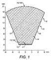
図1は、本発明の装置で用いる光起電力セル装置10の断面である。断面は横断面であり、光起電力セル装置10は押し出し形状として紙から延びている(実際、装置の材料は、押し出しプラスチック材料から成ってもよい)。 FIG. 1 is a cross section of a
図1の装置は、光起電材料のストリップ11の形態を成す単一の光起電力セル12を備えており、該光起電力セルは、この場合には、比較的低コストの単結晶光起電材料を備える。つまり、光起電力セル12は、その断面形状が図1から明らかである固体透明材料14を備える光学部品15の下面13に取り付けられて該下面と通じている。すなわち、形状が略放物面又は双曲面である対向する成形湾曲(側)面16、17が設けられるとともに、ある状況では平坦であるが通常は水晶体形状を成してもよい上面18が設けられる。上面18は入口開口18Aを形成し、また、下面13は、上面18に衝突する光(太陽の放射線)のための出口開口13Aを形成する。透明材料は、状況に適するパースペクス、PMMA、ポリスチレン、ポリカーボネート、ガラス、又は、ホウケイ酸ガラスなどの任意の透明材料であってもよいが、太陽の放射線を透過しなければならず、既知の屈折率を有する。面16、17の形状は特に屈折率によって決まる。光起電力セル12は下面13に接着接続されてもよいが、その場合、接着剤は関連する太陽放射線を透過しなければならない。 The apparatus of FIG. 1 comprises a single
あるいは、放射線を集中させるための光学素子を使用するため、他よりも少ない光起電材料を使用し、また、ある状況では、これは、より高性能で高価な光起電材料の使用を許容し得る。効率及びコストを最適化するため、いわゆる浮遊帯シリコンが好ましい光起電材料として使用されてもよい。この材料は、最大で約150mm直径の円柱結晶として成長され、通常はセミスクエア(Semi-Square)ウエハにカットされる。 Alternatively, it uses less photovoltaic material than others because it uses optical elements to concentrate the radiation, and in some situations this allows the use of higher performance and more expensive photovoltaic materials. Can do. To optimize efficiency and cost, so-called floating zone silicon may be used as a preferred photovoltaic material. This material is grown as cylindrical crystals with a maximum diameter of about 150 mm and is usually cut into Semi-Square wafers.
ほぼ全体のウエハが本発明者らの用途において2次元集光と同様に使用される場合には、ウエハからシリコンの更に35%を使用できる。直射日光のほぼ全てを年中捕捉するためにこの材料を用いると、片面セルの場合には材料の屈折率に応じて約4.5倍、セル利用全体の更に35%の利益の付加を伴う二次元構造の両面セル(後述する)の場合には約9倍集光できる。 If nearly the entire wafer is used in our application as well as two-dimensional focusing, an additional 35% of silicon from the wafer can be used. Using this material to capture almost all of the direct sunlight year-round, with the addition of a benefit of about 4.5 times depending on the refractive index of the material in the case of a single-sided cell and an additional 35% of the total cell usage In the case of a two-dimensional double-sided cell (described later), the light can be condensed about 9 times.
面16、17及び水晶体上面18の正確な形状は、材料の屈折率、受け入れ角度、及び、入射太陽放射線に対する光学素子15の傾斜配置によって決まる。直射日光捕捉及び周辺光進入を最大にしつつ光学材料及びセル材料の使用並びに直射日光進入を最小限に抑えるための最適化は、レイトレーシング(ray tracing)を必要とする。言うまでもなく、水晶体上面18の使用及び2つの対向する成形面16、17の相対的な方向により、光起電力セル12に通される太陽放射線が増大され、光起電力セル12のストリップの幅が他の場合よりも狭くなる。 The exact shape of the
成形面16、17及び屈折率は、入射太陽放射線による全内部反射が面16、17で存在するようになっている。 The molding surfaces 16 and 17 and the refractive index are such that total internal reflection by incident solar radiation exists at the
図1に戻って参照すると、光学部品15の断面形状は略楔形状であり、また、確かに成形面を平坦にできるが、光学部品15の断面形状は、その出口開口13Aに取り付けられる光起電力セル12に対して太陽光をより効果的に集光させる固体複合双曲型集光器(CHC)又は複合放物面集光器(CPC)光学素子(あるいは、それらに近似するもの。すなわち、曲線から始めて、それをレイトレーシングを考慮して特定の用途において、場合によっては装置の正確な位置決めに応じて僅かに変更する場合がある)であることが好ましい。 Referring back to FIG. 1, the cross-sectional shape of the
透明材料14は(実際に押し出され或いは成型されるかどうかにかかわらず)通常は直線的な押し出しである。 The
水晶体入口開口の利点は、側面の下部に反射面を有する必要なく良好な集光がなされ、また、同じ集光における材料の量がCPCからかなり減少されるという点である。 The advantage of the lens entrance aperture is that good light collection is achieved without having to have a reflective surface at the bottom of the side, and the amount of material in the same light collection is significantly reduced from CPC.
前記部品は光起電力部品10を形成する。 Said components form a
1つの構成において、光起電力部品は図1に示される直線的長さの断面であってもよい(装置のプラスチック部分の押し出しを可能にする)が、使用される光起電材料の量は、図1に示されるタイプの複数のセルの図1の断面に対して直角な断面を示す図9に示されるように、複数のこれらのセルが並んで配置されるようにすることによって更に減少されてもよい。これは、この断面の側面41、42が複合放物面形状又は複合双曲面形状を成してもよいことを示している。それぞれの光起電力部品10が4つの側面16、17、41、41を含むそのような構成は、通常、押し出しではなく成型を必要とする。 In one configuration, the photovoltaic component may be a linear length cross-section as shown in FIG. 1 (allowing extrusion of the plastic part of the device), but the amount of photovoltaic material used is Further reduction by arranging a plurality of these cells side by side as shown in FIG. 9 which shows a cross section perpendicular to the cross section of FIG. 1 of a plurality of cells of the type shown in FIG. May be. This indicates that the side surfaces 41 and 42 of the cross section may form a composite paraboloid shape or a composite hyperboloid shape. Such a configuration in which each
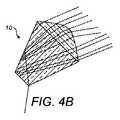
図4は、異なる角度で到達する太陽放射線に関する図1に示される部品10におけるレイトレースを示している。このように、太陽が天空で高いと、配置が図4Aに示されるようになり、また、太陽が天空で低いと、配置が図4Bに示されるようになる。 FIG. 4 shows a ray trace at the
図2は、建物で通常の透明(ガラス)パネルを交換するために、典型的な使用態様において、例えばグリーンハウス(ガラスハウス)又は温室などにおいて、どのくらいの長さの光起電力部品10(全体にわたって図1の断面を有する長さを備えてもよく、あるいは、図9に示されるタイプを成してもよい)を並べて配置できるのかを示している。図2の配置は3つの光起電力部品10を並べて示しているが、無論、更に多い数を並べて所望寸法のパネル19を形成してもよい。この場合、光起電力部品10のパネル19は、パネルが北半球では略南向きに水平に取り付けられるように配置されるが、略垂直線と北向きの屋根との間の角度は、個々の光学部品15の光軸が緯度角付近〜水平にほぼ配置された状態で、最大でおおよそ約24度を下回る緯度角まで任意であり、正確な度数は、光起電力部品が取り付けられる地表の地点の緯度によって決まる。 FIG. 2 shows how long a photovoltaic component 10 (overall) in a typical use, for example in a green house (glass house) or greenhouse, to replace a normal transparent (glass) panel in a building. 10 may be provided side by side with a length having the cross section of FIG. 1 or may be of the type shown in FIG. Although the arrangement of FIG. 2 shows three
再び図2を参照すると、それぞれの光起電力部品10における太陽光線用の入口開口18Aがトップラインであり、出口開口13Aがボトムラインである。側面は、受け入れ角度内の全ての光線において全内部反射を最大にするように形成される2つの(略双曲線の)曲線(この場合、直線に近い)である。この場合、これは押し出し形状にわたる断面である。 Referring to FIG. 2 again, the solar
図2は、一年の大半にわたって直射日光から内部空間を保護するとともに周辺光が可能な限り空間の内部に達することができるようにしつつ、約45度の緯度で水平面において一年中セルに集光される直接的な太陽放射線(直射日光)を最大にするように形成される光学系を示している。これは、固体光学素子とミラー面21との組み合わせを使用することによって達成される。なお、ミラー21は光学部品15から離間されており、光学部品の方に向くミラー21の側面は、(例えば、建物の内部の加熱を避けるために建物の内部へ向けて)セルの配列を通過する直射日光の量を減らすことが望ましい場合には反射せず、あるいは、逆に、より多くの周辺光が建物内へ伝えられるのが望ましい場合には反射してもよい。ミラー面21は、放射線を光起電力部品10の隣接する側面17から離れるように隣接する光起電力部品10の入口開口18Aへと反射するべく位置される。 Figure 2 shows the concentration of the cells in the horizontal plane at a latitude of about 45 degrees all year round, protecting the interior space from direct sunlight and allowing the ambient light to reach the interior of the space as much as possible for most of the year. 2 shows an optical system configured to maximize the direct solar radiation (direct sunlight) emitted. This is achieved by using a combination of solid optical elements and
言うまでもなく、光学素子15は、太陽からの直射日光である太陽放射線を受けて、その焦点を光起電材料13に合わせるように形成される。これは、側面16、17での全内部反射によって行なわれる。 Needless to say, the
この構成の利点のうちの1つは、空からの一般光である周辺光が異なる角度でパネル19に到達し、この光の大部分が光学部品を通過でき、それにより、パネル19の下側での照明が可能になるという点である。したがって、本発明のこの構成は、例えばガラスハウス又は温室において特に有用である、直射日光から光起電材料によって電気を生成でき、また、建物の内部は他の周辺光を受ける。このようにして、建物の内部は照明されるが、太陽の直接光線の殆どが光起電力セルによって集められるため、建物の内部は過熱されない。更に、電気が光起電力セルによって生成され、また、それらの冷却によって熱も生成される。太陽の光線を周辺光から分離できる理由の1つは、太陽の光線は光学部品の成形側面での全内部反射によって方向付けられるが、周辺光はそれらの側面に他の角度でぶつかって内部反射を伴うことなくそれらの側面を通過し得るからである。 One of the advantages of this configuration is that ambient light, which is general light from the sky, reaches the
塵埃が部品10の面に下側から到達できないようにして、周辺光が部品10を下向きに通過して内部空間内に下側から入ることができるようにする、透明材料の下側保護シート22。 A lower
セル15はヒートシンクに取り付けられる。なお、セル15は、その下面が開放しているため、空気冷却を行なうべく下側から空気によって冷却される。状況によっては、セル15が水平に対して小さく傾いて設けられ、それにより、透明シートがユニット下に取り付けられると、冷却空気流は、層流効果によって増大されて、内部空間に入ることが阻止される。 The
層流効果は、このタイプの構造が垂直であるときに大きく高められる。 Laminar flow effects are greatly enhanced when this type of structure is vertical.
パネル19全体は、上側からの塵埃及び天候を構成する要素から部品10を保護するための上側透明フィルム又はシート23を含む。 The
特に好ましい実施形態において、光起電力セル12は冷却装置によって冷却されてもよく、冷却装置はそれに取り付けられる水のチューブ又はヒートパイプを備え、また、この場合、下側保護シート22は必要とされず、透明材料のシート又はフィルムを構造の下側に取り付けることができる。 In a particularly preferred embodiment, the
図2では、緯度が45度であることを前提とするが、水平に対する部品10の傾きを変えることにより、他の緯度には水平構造が適する。 In FIG. 2, it is assumed that the latitude is 45 degrees, but by changing the inclination of the
システムの1つの利点は、太陽に面する任意の面において光学素子の同じ組み合わせを使用できるという点である。例えば、図3は、垂直壁で使用するのに適した同様の構成を示している。 One advantage of the system is that the same combination of optical elements can be used on any surface facing the sun. For example, FIG. 3 shows a similar configuration suitable for use with vertical walls.
図3の構成はミラー21を示しているが、セルに対する日光の多大な集光を生み出すために他の図に示されるミラー21を設けると幾つかの利点がある。 Although the configuration of FIG. 3 shows a
他の考慮すべき事項は熱である。最大で25%の光だけがシリコンセル12によって電気へ変換されるため(それどころか約18%)、セルが効率的に作動するように熱を除去することが望ましい。 Another consideration is heat. Since only up to 25% of the light is converted to electricity by the silicon cell 12 (rather about 18%), it is desirable to remove heat so that the cell operates efficiently.
これは、水などの熱伝達液体をセルの背後に運ぶチューブによって行なわれてもよい。 This may be done by a tube that carries a heat transfer liquid, such as water, behind the cell.
あるいは、金属ヒートシンクが光起電力セル12に取り付けられ、該ヒートシンクは、冷却用の空気流を可能にするべく利用できる。 Alternatively, a metal heat sink is attached to the
第3の装置は光起電力セル12に取り付けられるヒートパイプを使用し、また、熱は、他の場所で使用され或いは放散されるべく除去される。 The third device uses a heat pipe attached to the
第4の装置は光学素子の本体内で液体流を使用し、その場合、光学素子は単に中空形状であり、また、液体は屈折プロセスに関与する。 The fourth device uses a liquid flow within the body of the optical element, in which case the optical element is simply hollow and the liquid is involved in the refraction process.
本発明者らは、発生される熱が水加熱、暖房、及び、換気促進のために使用され得る貴重な資源であることに気が付いた。 The inventors have realized that the heat generated is a valuable resource that can be used for water heating, heating and ventilation enhancement.
空気冷却されて周辺光を建物内部へ到達させる必要がない構造は、アルミニウムのシートに取り付けて、直角に曲げる或いはプレスすることができる。 Structures that are air-cooled and do not require ambient light to reach the interior of the building can be attached to an aluminum sheet and bent or pressed at right angles.
ここで、別の光起電力セル装置の断面である図8を参照する。この光起電力セル装置において、光起電材料のストリップ11は、光学部品15の下面13に取り付けられるストリップとして設けられるのではなく、下面に隣接するが光学部品の本体の(出口開口13Aを与える)スロット内に配置されて、入口開口と略直角に配置される光起電材料のストリップの形態を成す。従来通り、光起電材料は、出口開口(スロットの側面)から全ての放射線を受けるように配置され、これは透明接着剤によって助けられる光起電材料の両側面11A、11Bは、光学部品15の両側面16、17から反射される入口開口からの放射線を受ける。この場合、側面16、17の上部は、図1を参照して説明したように複合放物面又は複合双曲面であってもよいが、下部16A、17Aは、放射線を光起電材料の両側面へ反射するように内側に方向付けられて形成されてもよく、また、これらの下部16A、17Aが鏡張りであってもよい(すなわち、鏡面を直接的に或いは間接的に含む)。 Reference is now made to FIG. 8, which is a cross section of another photovoltaic cell device. In this photovoltaic cell device, the
図1の光起電力セルの使用と同様に、図8の複数の光起電力セルは、図2又は図3又は図6又は図7に示される態様と同様の態様で配置されてもよい。したがって、これらのセルは並んで配置されてパネルを形成してもよく、また、光学部品の光軸は、互いに平行であるが、パネルの平面に対して角度を成す。この場合、入口開口ではなく側面にぶつかる太陽放射線を隣接する光起電力セルの入口開口へ反射するために、各光学部品間に鏡面21を設けてもよい。 Similar to the use of the photovoltaic cell of FIG. 1, the plurality of photovoltaic cells of FIG. 8 may be arranged in a manner similar to that shown in FIG. 2 or FIG. 3 or FIG. 6 or FIG. Thus, these cells may be arranged side by side to form a panel, and the optical axes of the optical components are parallel to each other but at an angle to the plane of the panel. In this case, a
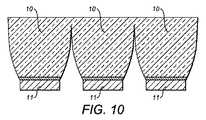
図10は、図8に示されるタイプの複数のセルの図8の断面に対して直角な断面であり、図1に関する図9の配置に相当する。これは、この断面の側面25、26が複合放物線面状又は複合双曲面形状を成してもよいことを示している。 10 is a cross section perpendicular to the cross section of FIG. 8 of a plurality of cells of the type shown in FIG. 8 and corresponds to the arrangement of FIG. 9 with respect to FIG. This indicates that the side surfaces 25 and 26 of the cross section may form a compound parabolic surface shape or a compound hyperboloid shape.
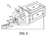
ここで、ガラス壁を有するグリーンハウス26(すなわち、ガラスハウス)、温室、又は、ガラス屋根付きのショッピングセンターなどの建物に対して光起電力部品10のパネルがどのようにして適用され得るのかを示す図5を参照する。図示の構成では、グリーンハウス26は、その屋根に取り付けられる部品10の第1のパネル27と、第2の同様のパネル28とを含む。パネル27は図2に示されるタイプのものであってもよく、また、第2のパネル28は図3に示される対象のものであってもよい。 Here, how a panel of
各パネル27、28には、各パネルで光起電材料12により生成される電気を単にバッテリ31として示される蓄電装置へ送る電気接続部29が接続される。また、電気接続部29は、ランプ32又はファン33などの空調装置、あるいは、水タンク36の形態を成す水供給源を加熱するための電気加熱装置34に接続されてもよい。 Each
温水タンク36は、例えばラジエータ37の形態を成す暖房装置に接続されてもよい。 The hot water tank 36 may be connected to a heating device in the form of a
更に、光起電材料12を冷却するための冷却装置が冷却水を利用する前述した構成を備えてもよく、また、冷却水は、水を加熱するための温水タンク36内の熱交換器38へと直接に送られてもよい。 Further, the cooling device for cooling the
そのような構成は非常に効率的である。したがって、太陽光は通常の態様でグリーンハウス内に入り込む。太陽光の大部分が捕捉されて光起電材料12へ送られるが、この場合、一部の太陽光は、図2の下側保護シート22を介して第1及び第2のパネル27、28を通過し、そのため、太陽のパワーが最も強い日中にわたって、温度を適切に加減するための何らかの日陰がグリーンハウス26内に存在する。 Such a configuration is very efficient. Therefore, sunlight enters the green house in the normal manner. Most of the sunlight is captured and sent to the
このように、パネル26、27の形態を成す本発明の構成は、2つの機能、すなわち、第1に、グリーンハウス26の壁及び屋根を通る太陽光全体を加減する機能、及び、第2に、光起電材料12を介して電気を生成するために捕捉された太陽光が使用されるという機能を有する。また、熱は、光起電材料12及び光起電力部品10の他の部分から水冷却システムによって除去され、その熱は、その後、温水タンク36内の水へと送られる。 Thus, the configuration of the present invention in the form of panels 26, 27 has two functions: first, the function of adjusting the total sunlight passing through the walls and roof of the green house 26; and second, , Having the function of using captured sunlight to generate electricity through the
夜間、グリーンハウス26内の温度が通常はかなり降下し、したがって、タンク36内の温水をラジエータ37を通じて循環させて、グリーンハウス内の温度を高め、それにより、グリーンハウス内の植物の成長を向上させて促進させてもよい。また、バッテリ31に蓄えられる電気を使用して、グリーンハウス内の有効採光時間を延ばすために使用されてもよいランプ32を作動させてもよく、この場合にも先と同様、グリーンハウス内の植物の成長が促進される。更に、太陽光が特に明るい真っ昼間においては、再びグリーンハウス内の温度を加減するために、ファン33によって行なわれる空調がONに切り換えられてもよい。ある状況では、煙突/層流効果がファンが無くても換気を促進できるため、ファンがONに切り換えられる必要がない。 At night, the temperature in the green house 26 usually drops considerably, so the hot water in the tank 36 is circulated through the
水平構造及び垂直構造は、(グリーンハウス以外の)新たな建物で使用されてもよく、また、二重ガラスの屋根及び壁にそれぞれ埋め込まれてもよい。したがって、二重ガラスを含むシステムは、建物の屋根及び壁、すなわち、ドラマティックで興趣深く見える建築に存分の腕を振るわせる建物の被覆体を備える。 Horizontal and vertical structures may be used in new buildings (other than green houses) and may be embedded in double glazing roofs and walls, respectively. Thus, systems that include double glazing include building roofs and walls, i.e., building coverings that make the most of a dramatic and entertaining architecture.
図6及び図7は、図示のパネルが建物の外側の水平及び垂直固体面でそれぞれ使用される点を除き図2及び図3の図に類似する図である。この場合、周辺光がパネルを通過する必要はなく、したがって、構造が僅かに異なる。 6 and 7 are similar to the views of FIGS. 2 and 3 except that the illustrated panels are used on horizontal and vertical solid surfaces outside the building, respectively. In this case, ambient light does not need to pass through the panel and therefore the structure is slightly different.
パネル19が関連する壁面から離間される場合には、特に図7の垂直構造の場合には、空気が垂直壁の外面とパネルの後面との間の隙間40を通過できるようにしてもよい。冬季には、外気が、壁とパネルとの間の隙間の下縁へ送られて上方へ移動され、壁の上端で建物内に入れられてもよい。このようにして、光起電力セルの背後からの熱が建物内へ送られる。夏には、構成が異なってもよく、建物の内側からの空気は、壁の下縁の適切な開口から供給されて、隙間40を通じて上方へ移動され、建物の外側の大気へと外方へ送られる。この場合、空気を建物の内側から引き出し、それにより、建物を効果的に空調する。これは、固体壁のある建物において有用であるが、グリーンハウス並びに透明な壁及び屋根において使用されてもよい。 If the
図6及び図7におけるミラー位置は、図2及び図3における集光よりも多くの集光を可能にするが、内部に達する周辺光を減少させる。ある場合には、これは、周辺光が重大とはなり得ない垂直壁において特に有用な利点である。 The mirror positions in FIGS. 6 and 7 allow more light collection than in FIGS. 2 and 3, but reduce ambient light reaching the interior. In some cases, this is a particularly useful advantage in vertical walls where ambient light cannot be significant.
例えば家庭の家屋(更には英国において)又は同様の建物での前述したパネルの使用は、家(及び、場合によっては自家用車において)を給電するのに十分すぎるほどの電気及び熱を発生させるはずである。スペインなどの更に南方の地方では、配管網へ多量の電気を輸送できるようにするために十分な電気が生成されなければならない。良好な気候のグリーンハウスでは、システムが発電所になってもよい。その場合、冷却負荷及び加熱負荷が減少するため、グリーンハウスの稼動はかなり費用効率が高い。 For example, the use of the aforementioned panels in a home (or even in the UK) or similar building should generate enough electricity and heat to power the house (and possibly in a private car) It is. In more southern regions such as Spain, enough electricity must be generated to be able to transport large amounts of electricity to the piping network. In a green house with good climate, the system may be a power plant. In that case, the operation of the greenhouse is quite cost-effective because the cooling and heating loads are reduced.
したがって、このようにして、良く知られているように光起電材料を使用して電気を集めるだけでなく、太陽放射線を光起電材料に対して集光する光学系を設けることにより更に少ない量の光起電材料を利用すると同時に、光起電材料及び他の部品を冷却し、例えば夜間に外部の温度が下がるときにその熱を利用して建物の内部を暖かく保つ。グリーンハウス26に適用される本発明の装置を示してきたが、該装置は、例えば建物に取り付けられるガラス温室で同様に利用されてもよく、あるいは、単に、通常の建物の関連する屋根及び壁、すなわち、固体壁に適用されてもよく、あるいは、半透明壁を形成することができる。 Thus, in this way, it is even less by providing an optical system that not only collects electricity using a photovoltaic material as is well known, but also collects solar radiation onto the photovoltaic material. At the same time that the amount of photovoltaic material is utilized, the photovoltaic material and other components are cooled and the interior of the building is kept warm, for example, when the outside temperature falls at night. Although the device of the present invention applied to the green house 26 has been shown, the device may be used in a glass greenhouse as well, for example, attached to a building, or simply associated roofs and walls of a normal building. That is, it may be applied to a solid wall or it can form a translucent wall.
したがって、本発明者らは、装置上に降りかかる太陽光子を十分に利用して、それらを用途を考慮した有用な出力へと変換するとともに、直射日光が望まれていない場所へ伝えられるのを阻止する。 Therefore, the inventors fully utilize the photons falling on the device to convert them into useful outputs considering the application and prevent direct sunlight from being transmitted to undesired locations. To do.
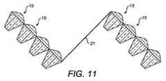
図11は、光起電力セル装置がグループを成して配置されるパネル構成を示している。ミラー21をそれぞれの個々の光学部品の側面に隣接させるのではなく、第1のグループのセルの入口開口に達しない放射線を第2のグループの1つ以上のセルの入口開口へと反射するように位置される鏡面21が光起電力装置の特定のグループにおいて設けられる。 FIG. 11 shows a panel configuration in which photovoltaic cell devices are arranged in groups. Rather than having a
本発明は前述した例の細部に限定されない。太陽エネルギの更に一層の効果的使用のため、様々な他の特徴が本発明の装置に組み入れられてもよい。 The invention is not limited to the details of the examples described above. Various other features may be incorporated into the apparatus of the present invention for even more effective use of solar energy.
したがって、例えば、光起電材料12が他の電気部品と一体化されてもよい。光起電材料12がセルを分離するように分けられてもよく、また、太陽の範囲内に十分にないそれらのセルを切り離すためにカットアウトダイオードが設けられてもよい。問題の1つは、全てのセルが通常のごとく直列に接続されれば、1日の特定の時間にパネルの一部が日陰に入る場合に、パネルの出力が減少されるという点である。電気を生成していないそれらのセルを切り離すためのカットアウトダイオードの使用により、出力を保つことができる。 Thus, for example, the
例えば、出力のより効果的な生成のために、他の特徴、例えば、光センサ、電力調整、熱管理、プラグ、及び、隣接する部品に対するプラグ&プレイ相互接続を装置に組み入れることができる。 For example, other features such as light sensors, power conditioning, thermal management, plugs, and plug and play interconnections to adjacent components can be incorporated into the device for more efficient generation of output.
例えば、様々な目的のためのエレクトロニクスを装置に組み込むことができ、その場合、太陽から受けられて光起電力セルによって変換される電力は、センサ、制御装置、及び、建物管理システムの中央制御ユニットとの無線通信などのエレクトロニクスに給電する。 For example, electronics for various purposes can be incorporated into the device, in which case the power received from the sun and converted by the photovoltaic cell is the central control unit of the sensor, controller and building management system To power electronics such as wireless communications.
光起電力セルを有するこの光給電システムと通常の光給電システムとの間の違いの1つは、プロセッサ効率のためのものと同じヒートシンクを光起電力セル効率のために使用する同じ単一の部品に光学素子が組み込まれるという点である。 One difference between this photovoltaic system with photovoltaic cells and a regular photovoltaic system is that the same single heat sink is used for photovoltaic cell efficiency as for the processor efficiency. The optical element is incorporated into the component.
第2の違いは、光起電力セルのための通常のガラスカバーとは異なり、光学素子がそれに到達する太陽光子を最大限に利用するよう特別に形成されるという点である。これは、1年を通じて太陽の様々な位置を考慮する必要があり、様々な太陽スペクトルは、太陽位置及び大気状態、周辺の直射日光の異なる方法での使用、及び、発生される熱の使用に依存する。 The second difference is that, unlike a normal glass cover for photovoltaic cells, the optical element is specially formed to make the best use of the sunlight that reaches it. This requires taking into account the different positions of the sun throughout the year, and the different solar spectra are used for different methods of solar position and atmospheric conditions, ambient direct sunlight, and the use of generated heat. Dependent.
第3の違いは、太陽光子のこの効率的な使用を達成するために、自動で変更されようと手動で変更されようと、装置が正確に方向付けられて特定の位置に永久に固定され或いは一時的に位置付けられなければならないという点である。 The third difference is that in order to achieve this efficient use of solar photons, the device is correctly oriented and permanently fixed in a specific position, whether automatically changed or manually changed. It must be temporarily positioned.
この光学素子の場合、そのローバスト性は、装置が電子素子及び更には熱管理システムを安全に保護し且つ別個の構造化されたハジングの必要性を避けるのに十分な構造を与える。 In the case of this optical element, its robustness provides a structure sufficient for the device to safely protect the electronic element and even the thermal management system and avoid the need for a separate structured housing.
本発明者らは、ある状況で本発明の装置が建物の優れた被覆体としての機能を果たし、それにより、内部要素を外側要素から保護して、それらを良好な状態及び貴重なリソースを内側に与えるように変換することを想起する。 The inventors have found that in certain situations the device of the present invention serves as an excellent covering for buildings, thereby protecting the inner elements from the outer elements, keeping them in good condition and valuable resources on the inside. Recall that the conversion to give to.
本発明者らは、一例として様々な構造を想定する。
本発明は、前述した例の細部に限定されない。 The invention is not limited to the details of the examples described above.
本発明の様々な好ましい実施形態を説明してきたが、本発明のこれらの実施形態又はその一部が本発明の範囲から逸脱することなく使用できるように必要に応じて組み合わされてもよいことが想起される。 Although various preferred embodiments of the present invention have been described, it is possible that these embodiments of the present invention or portions thereof may be combined as needed so that they can be used without departing from the scope of the present invention. Recalled.
角度を含む寸法への言及は単なる一例である。特に反射面の形状及び寸法は、一例であり、装置が使用されるべき状況、例えば装置が使用されるべき地球上の場所及び装置が取り付けられる(コンパス)方向に応じて異なる。一般に、寸法及び角度は、太陽の角度に対して設定されるとともに、固定された設備において最大の効果を得るために分点における正午の太陽の方向に対して合わされる。 Reference to a dimension that includes an angle is merely an example. In particular, the shape and dimensions of the reflecting surface are examples, and differ depending on the situation in which the device is to be used, for example the location on the earth where the device is to be used and the direction in which the device is mounted (compass). In general, the dimensions and angles are set relative to the sun angle and are aligned with the direction of the noon sun at the dividing point in order to obtain maximum effect in a fixed installation.
本発明を園芸環境に適用する場合、特定の緯度における特定の植物は、特定量の光及び紫外線などの特定の周波数を必要とする。これを最もうまく達成するために、変数を最適化できる。結果として、全ての方向の太陽光を締め出すことが必ずしも都合が良いとは限らない。 When applying the present invention to a horticultural environment, certain plants at certain latitudes require certain frequencies such as certain amounts of light and ultraviolet light. To achieve this best, variables can be optimized. As a result, it is not always convenient to keep out sunlight in all directions.
第2に、1年の半分の冬に空調が必要とされる可能性が高くない高緯度の国では、光起電力装置の受け入れ角度が太陽の夏経路だけを含むことが、建物における全エネルギ生成においてより効率的な場合がある。冬季において、直射日光は、必要とされる光及び暖かさを建物に直にもたらし、また、装置のこの構造を伴う屋根の取り付けは、受け入れ角度が夏及び冬の両方における太陽の経路を含んでいた場合に生成される比較的少量の電気よりも貴重である。 Second, in high-latitude countries where air conditioning is not likely to be required in the winter of half a year, the acceptance angle of the photovoltaic device includes only the solar summer path, generating total energy in the building May be more efficient. In the winter, direct sunlight brings the required light and warmth directly to the building, and the roof mounting with this structure of the device includes a solar path where the acceptance angle is both summer and winter. It is more valuable than the relatively small amount of electricity that would be generated.
Claims (22)
Translated fromJapanese冷却手段によって除去された熱を光起電力セルから蓄熱器へと伝えるための熱伝達手段と、
蓄熱器から熱を引き出すための手段と、
を含む、請求項13から請求項16のいずれか一項に記載の複数の光起電力装置。Cooling means for cooling the photovoltaic cells;
Heat transfer means for transferring heat removed by the cooling means from the photovoltaic cell to the regenerator;
Means for extracting heat from the regenerator;
A plurality of photovoltaic devices according to any one of claims 13 to 16, comprising:
光起電力セルを冷却するための冷却手段と、
冷却手段によって除去された熱を光起電力セルから蓄熱器へと伝えるための熱伝達手段と、
蓄熱器から熱を引き出すための手段と、
を備える、光起電力装置。One or more photovoltaic cells for receiving radiation;
Cooling means for cooling the photovoltaic cells;
Heat transfer means for transferring heat removed by the cooling means from the photovoltaic cell to the regenerator;
Means for extracting heat from the regenerator;
A photovoltaic device comprising:
Applications Claiming Priority (3)
| Application Number | Priority Date | Filing Date | Title |
|---|---|---|---|
| GB0816113.5 | 2008-09-04 | ||
| GBGB0816113.5AGB0816113D0 (en) | 2008-09-04 | 2008-09-04 | Photvoltaic cell apparatus |
| PCT/GB2009/051099WO2010026415A2 (en) | 2008-09-04 | 2009-09-01 | Photovoltaic cell apparatus |
Publications (1)
| Publication Number | Publication Date |
|---|---|
| JP2012502458Atrue JP2012502458A (en) | 2012-01-26 |
Family
ID=39888756
Family Applications (1)
| Application Number | Title | Priority Date | Filing Date |
|---|---|---|---|
| JP2011525621AWithdrawnJP2012502458A (en) | 2008-09-04 | 2009-09-01 | Photovoltaic cell device |
Country Status (8)
| Country | Link |
|---|---|
| US (1) | US20110209743A1 (en) |
| EP (1) | EP2332179A2 (en) |
| JP (1) | JP2012502458A (en) |
| KR (1) | KR20110067118A (en) |
| CN (1) | CN102160195A (en) |
| GB (2) | GB0816113D0 (en) |
| IL (1) | IL211568A0 (en) |
| WO (1) | WO2010026415A2 (en) |
Cited By (2)
| Publication number | Priority date | Publication date | Assignee | Title |
|---|---|---|---|---|
| US9853175B2 (en) | 2014-09-22 | 2017-12-26 | Kabushiki Kaisha Toshiba | Solar cell module |
| JP2021516534A (en)* | 2018-02-23 | 2021-07-01 | ファイオン・テクノロジーズ・コーポレイションPhion Technologies Corp. | Transmitter / receiver assembly for free space power transfer and data communication systems |
Families Citing this family (7)
| Publication number | Priority date | Publication date | Assignee | Title |
|---|---|---|---|---|
| CA2840968A1 (en)* | 2011-07-06 | 2013-01-10 | The Regents Of The University Of Michigan | Integrated solar collectors using epitaxial lift off and cold weld bonded semiconductor solar cells |
| KR101282197B1 (en)* | 2011-10-10 | 2013-07-04 | (주) 비제이파워 | Solar condensing module system for utilizing lens |
| KR101282192B1 (en)* | 2011-10-10 | 2013-07-04 | (주) 비제이파워 | Solar condensing module system for utilizing reflected light |
| GB2497327A (en)* | 2011-12-07 | 2013-06-12 | On Sun Systems Ltd | Support for holding a Optical component and a Photovoltaic Package |
| GB2497942B (en) | 2011-12-22 | 2014-08-27 | Univ Glasgow | Optical element |
| FR3042260A1 (en)* | 2015-10-13 | 2017-04-14 | Sunpartner Technologies | SOLAR PHOTOVOLTAIC PANEL WHOSE TRANSPARENCY VARIES ACCORDING TO THE RELATIVE POSITION OF THE SUN |
| WO2020148743A1 (en)* | 2019-01-20 | 2020-07-23 | Peter Graner | Micro electric power station and micro grid |
Family Cites Families (20)
| Publication number | Priority date | Publication date | Assignee | Title |
|---|---|---|---|---|
| US4029519A (en)* | 1976-03-19 | 1977-06-14 | The United States Of America As Represented By The United States Energy Research And Development Administration | Solar collector having a solid transmission medium |
| US4143234A (en)* | 1976-11-08 | 1979-03-06 | Monsanto Company | Solar collector using total internal reflectance |
| US4143233A (en)* | 1977-06-06 | 1979-03-06 | Monsanto Research Corporation | Solar energy collector |
| US4246643A (en)* | 1978-02-13 | 1981-01-20 | Pitney Bowes Inc. | Low cost postage applicator |
| DE2926754A1 (en)* | 1979-07-03 | 1981-01-15 | Licentia Gmbh | SOLAR CELL ARRANGEMENT |
| US4248643A (en)* | 1979-11-19 | 1981-02-03 | Walter Todd Peters | Solar energy conversion panel |
| US5255666A (en)* | 1988-10-13 | 1993-10-26 | Curchod Donald B | Solar electric conversion unit and system |
| US5091018A (en)* | 1989-04-17 | 1992-02-25 | The Boeing Company | Tandem photovoltaic solar cell with III-V diffused junction booster cell |
| US5180441A (en)* | 1991-06-14 | 1993-01-19 | General Dynamics Corporation/Space Systems Division | Solar concentrator array |
| US6057505A (en)* | 1997-11-21 | 2000-05-02 | Ortabasi; Ugur | Space concentrator for advanced solar cells |
| US6700054B2 (en)* | 1998-07-27 | 2004-03-02 | Sunbear Technologies, Llc | Solar collector for solar energy systems |
| US6384320B1 (en)* | 2000-10-13 | 2002-05-07 | Leon Lung-Chen Chen | Solar compound concentrator of electric power generation system for residential homes |
| US20050081909A1 (en)* | 2003-10-20 | 2005-04-21 | Paull James B. | Concentrating solar roofing shingle |
| EP1844267A4 (en)* | 2003-12-11 | 2011-07-06 | Tech Solar Ltd | SOLAR ENERGY CAPTURING SYSTEM |
| AU2007207582A1 (en)* | 2006-01-17 | 2007-07-26 | Soliant Energy, Inc. | Concentrating solar panel and related systems and methods |
| AU2007269051A1 (en)* | 2006-07-05 | 2008-01-10 | Stellaris Corporation | Apparatus and method for forming a photovoltaic device |
| ES2654300T3 (en)* | 2006-09-28 | 2018-02-13 | Trac Group Holdings Ltd | Solar energy collection device |
| US7612285B2 (en)* | 2007-01-08 | 2009-11-03 | Edtek, Inc. | Conversion of solar energy to electrical and/or heat energy |
| IL181517A0 (en)* | 2007-02-22 | 2007-07-04 | Ivgeni Katz | Solar cell optical system |
| US20090101207A1 (en)* | 2007-10-17 | 2009-04-23 | Solfocus, Inc. | Hermetic receiver package |
- 2008
- 2008-09-04GBGBGB0816113.5Apatent/GB0816113D0/ennot_activeCeased
- 2009
- 2009-09-01GBGB1104759Apatent/GB2475457A/ennot_activeWithdrawn
- 2009-09-01USUS13/062,107patent/US20110209743A1/ennot_activeAbandoned
- 2009-09-01KRKR1020117007796Apatent/KR20110067118A/ennot_activeWithdrawn
- 2009-09-01EPEP09785559Apatent/EP2332179A2/ennot_activeWithdrawn
- 2009-09-01JPJP2011525621Apatent/JP2012502458A/ennot_activeWithdrawn
- 2009-09-01WOPCT/GB2009/051099patent/WO2010026415A2/enactiveApplication Filing
- 2009-09-01CNCN2009801348832Apatent/CN102160195A/enactivePending
- 2011
- 2011-03-03ILIL211568Apatent/IL211568A0/enunknown
Cited By (7)
| Publication number | Priority date | Publication date | Assignee | Title |
|---|---|---|---|---|
| US9853175B2 (en) | 2014-09-22 | 2017-12-26 | Kabushiki Kaisha Toshiba | Solar cell module |
| JP2021516534A (en)* | 2018-02-23 | 2021-07-01 | ファイオン・テクノロジーズ・コーポレイションPhion Technologies Corp. | Transmitter / receiver assembly for free space power transfer and data communication systems |
| US11600643B2 (en) | 2018-02-23 | 2023-03-07 | Phion Technologies Corp. | Assembly for optical to electrical power conversion transfer |
| US11616087B2 (en) | 2018-02-23 | 2023-03-28 | Phion Technologies Corp. | Transceiver assembly for free space power transfer and data communication system |
| JP2023126811A (en)* | 2018-02-23 | 2023-09-12 | ファイオン・テクノロジーズ・コーポレイション | Transmitter-receiver assembly for free space power transmission and data communication system |
| US11876105B2 (en) | 2018-02-23 | 2024-01-16 | Phion Technologies Llc | Laser light collecting assembly for a wireless power receiver |
| US12132059B2 (en) | 2018-02-23 | 2024-10-29 | Phion Technologies Corp. | Method for safe and secure free space power and data transfer |
Also Published As
| Publication number | Publication date |
|---|---|
| WO2010026415A2 (en) | 2010-03-11 |
| KR20110067118A (en) | 2011-06-21 |
| US20110209743A1 (en) | 2011-09-01 |
| IL211568A0 (en) | 2011-05-31 |
| GB2475457A (en) | 2011-05-18 |
| GB201104759D0 (en) | 2011-05-04 |
| CN102160195A (en) | 2011-08-17 |
| EP2332179A2 (en) | 2011-06-15 |
| WO2010026415A3 (en) | 2010-07-15 |
| GB0816113D0 (en) | 2008-10-15 |
Similar Documents
| Publication | Publication Date | Title |
|---|---|---|
| JP2012502458A (en) | Photovoltaic cell device | |
| JP5497037B2 (en) | Solar energy conversion | |
| EP1935032B1 (en) | Photovoltaic roof ridge cap and installation method | |
| US20070056579A1 (en) | Energy Channeling Sun Shade System and Apparatus | |
| US20080308090A1 (en) | Solar Concentrator | |
| CN103022206B (en) | Groove-type compound parabolic concentrating power generation component | |
| US20180054159A1 (en) | Light collection and redirection to a solar panel | |
| US20130199515A1 (en) | Skylight energy management system | |
| KR102089366B1 (en) | Back side penetration type photovoltaic system | |
| JP2004214423A (en) | Solar power system | |
| CN214591306U (en) | Solar photoelectric curtain wall | |
| JP4313841B1 (en) | Solar lens and solar-powered equipment | |
| RU2612725C1 (en) | Hybrid roof solar panel | |
| JP2007214235A (en) | Solar-ray energy composite using system device | |
| CN117836675A (en) | Prismatic solar concentrator | |
| WO2013095120A1 (en) | Solar concentrator system | |
| US20220286081A1 (en) | Pv-chimney | |
| KR102656003B1 (en) | frame for setting solar module | |
| KR101121638B1 (en) | Solar concentrator | |
| RU173744U1 (en) | SOLAR BATTERY WITH INCREASING GLASS | |
| TR2022011833A2 (en) | AMPLIFIER AND CONVERTER PORTABLE SYSTEM FOR ELECTRICITY GENERATION FROM SOLAR PANELS | |
| JP2003303989A (en) | Solar cell module | |
| KR100235454B1 (en) | Light-converging optical system converged light utilizing devices and installation method thereof | |
| HK1178963B (en) | Solar energy conversion | |
| ITMI20090224A1 (en) | DEVICE FOR THE CONVERSION OF SOLAR ENERGY IN THERMAL AND ELECTRIC ENERGY. |
Legal Events
| Date | Code | Title | Description |
|---|---|---|---|
| A300 | Application deemed to be withdrawn because no request for examination was validly filed | Free format text:JAPANESE INTERMEDIATE CODE: A300 Effective date:20121106 |