JP2012502314A - Optical sheet and composite sheet having moiré fringes, and backlight assembly including the sheet - Google Patents
Optical sheet and composite sheet having moiré fringes, and backlight assembly including the sheetDownload PDFInfo
- Publication number
- JP2012502314A JP2012502314AJP2011525994AJP2011525994AJP2012502314AJP 2012502314 AJP2012502314 AJP 2012502314AJP 2011525994 AJP2011525994 AJP 2011525994AJP 2011525994 AJP2011525994 AJP 2011525994AJP 2012502314 AJP2012502314 AJP 2012502314A
- Authority
- JP
- Japan
- Prior art keywords
- pattern
- array
- layer
- sheet
- pattern array
- Prior art date
- Legal status (The legal status is an assumption and is not a legal conclusion. Google has not performed a legal analysis and makes no representation as to the accuracy of the status listed.)
- Pending
Links
- 230000003287optical effectEffects0.000titleclaimsabstractdescription101
- 239000002131composite materialSubstances0.000titleclaimsabstractdescription25
- 239000000758substrateSubstances0.000claimsdescription106
- 239000000463materialSubstances0.000claimsdescription59
- 239000000853adhesiveSubstances0.000claimsdescription34
- 230000001070adhesive effectEffects0.000claimsdescription34
- 229920005989resinPolymers0.000claimsdescription25
- 239000011347resinSubstances0.000claimsdescription25
- 238000009792diffusion processMethods0.000claimsdescription23
- 229920000139polyethylene terephthalatePolymers0.000claimsdescription12
- 239000005020polyethylene terephthalateSubstances0.000claimsdescription12
- 239000003822epoxy resinSubstances0.000claimsdescription7
- 229920000647polyepoxidePolymers0.000claimsdescription7
- 229920002803thermoplastic polyurethanePolymers0.000claimsdescription7
- 229920003229poly(methyl methacrylate)Polymers0.000claimsdescription6
- -1polyethylene terephthalatePolymers0.000claimsdescription6
- 239000004926polymethyl methacrylateSubstances0.000claimsdescription6
- GHMLBKRAJCXXBS-UHFFFAOYSA-NresorcinolChemical compoundOC1=CC=CC(O)=C1GHMLBKRAJCXXBS-UHFFFAOYSA-N0.000claimsdescription6
- 229920002554vinyl polymerPolymers0.000claimsdescription6
- JOYRKODLDBILNP-UHFFFAOYSA-NEthyl urethaneChemical compoundCCOC(N)=OJOYRKODLDBILNP-UHFFFAOYSA-N0.000claimsdescription5
- 239000004593EpoxySubstances0.000claimsdescription4
- 239000004952PolyamideSubstances0.000claimsdescription4
- NIXOWILDQLNWCW-UHFFFAOYSA-Nacrylic acid groupChemical groupC(C=C)(=O)ONIXOWILDQLNWCW-UHFFFAOYSA-N0.000claimsdescription4
- 229920002647polyamidePolymers0.000claimsdescription4
- 229920000877Melamine resinPolymers0.000claimsdescription3
- ISWSIDIOOBJBQZ-UHFFFAOYSA-NPhenolChemical compoundOC1=CC=CC=C1ISWSIDIOOBJBQZ-UHFFFAOYSA-N0.000claimsdescription3
- 239000004698PolyethyleneSubstances0.000claimsdescription3
- 239000004793PolystyreneSubstances0.000claimsdescription3
- 239000004372Polyvinyl alcoholSubstances0.000claimsdescription3
- XSQUKJJJFZCRTK-UHFFFAOYSA-NUreaChemical compoundNC(N)=OXSQUKJJJFZCRTK-UHFFFAOYSA-N0.000claimsdescription3
- XTXRWKRVRITETP-UHFFFAOYSA-NVinyl acetateChemical compoundCC(=O)OC=CXTXRWKRVRITETP-UHFFFAOYSA-N0.000claimsdescription3
- BZHJMEDXRYGGRV-UHFFFAOYSA-NVinyl chlorideChemical compoundClC=CBZHJMEDXRYGGRV-UHFFFAOYSA-N0.000claimsdescription3
- DHKHKXVYLBGOIT-UHFFFAOYSA-Nacetaldehyde Diethyl AcetalNatural productsCCOC(C)OCCDHKHKXVYLBGOIT-UHFFFAOYSA-N0.000claimsdescription3
- 125000002777acetyl groupChemical class[H]C([H])([H])C(*)=O0.000claimsdescription3
- 239000004202carbamideSubstances0.000claimsdescription3
- JDSHMPZPIAZGSV-UHFFFAOYSA-NmelamineChemical compoundNC1=NC(N)=NC(N)=N1JDSHMPZPIAZGSV-UHFFFAOYSA-N0.000claimsdescription3
- 229920000515polycarbonatePolymers0.000claimsdescription3
- 239000004417polycarbonateSubstances0.000claimsdescription3
- 229920000728polyesterPolymers0.000claimsdescription3
- 229920000573polyethylenePolymers0.000claimsdescription3
- 229920002451polyvinyl alcoholPolymers0.000claimsdescription3
- 229920006395saturated elastomerPolymers0.000claimsdescription3
- 229920005992thermoplastic resinPolymers0.000claimsdescription3
- 229920001187thermosetting polymerPolymers0.000claimsdescription3
- 229920006305unsaturated polyesterPolymers0.000claimsdescription3
- 125000000391vinyl groupChemical group[H]C([*])=C([H])[H]0.000claimsdescription3
- 238000004519manufacturing processMethods0.000abstractdescription21
- 239000010410layerSubstances0.000description465
- 238000000034methodMethods0.000description27
- 239000004973liquid crystal related substanceSubstances0.000description18
- 239000010408filmSubstances0.000description15
- 239000012788optical filmSubstances0.000description13
- 238000002834transmittanceMethods0.000description11
- 238000005259measurementMethods0.000description6
- 238000003491arrayMethods0.000description5
- 230000001678irradiating effectEffects0.000description4
- 238000010586diagramMethods0.000description3
- 230000000694effectsEffects0.000description3
- 238000002474experimental methodMethods0.000description3
- 238000010030laminatingMethods0.000description3
- 239000000126substanceSubstances0.000description3
- 239000004925Acrylic resinSubstances0.000description2
- 229920000178Acrylic resinPolymers0.000description2
- 239000000654additiveSubstances0.000description2
- TZCXTZWJZNENPQ-UHFFFAOYSA-Lbarium sulfateChemical compound[Ba+2].[O-]S([O-])(=O)=OTZCXTZWJZNENPQ-UHFFFAOYSA-L0.000description2
- 230000005540biological transmissionEffects0.000description2
- 239000011248coating agentSubstances0.000description2
- 238000000576coating methodMethods0.000description2
- 239000000470constituentSubstances0.000description2
- 229920006332epoxy adhesivePolymers0.000description2
- 239000011521glassSubstances0.000description2
- 239000003292glueSubstances0.000description2
- 239000002994raw materialSubstances0.000description2
- QNRATNLHPGXHMA-XZHTYLCXSA-N(r)-(6-ethoxyquinolin-4-yl)-[(2s,4s,5r)-5-ethyl-1-azabicyclo[2.2.2]octan-2-yl]methanol;hydrochlorideChemical compoundCl.C([C@H]([C@H](C1)CC)C2)CN1[C@@H]2[C@H](O)C1=CC=NC2=CC=C(OCC)C=C21QNRATNLHPGXHMA-XZHTYLCXSA-N0.000description1
- 239000004970Chain extenderSubstances0.000description1
- 239000004375DextrinSubstances0.000description1
- 229920001353DextrinPolymers0.000description1
- WHXSMMKQMYFTQS-UHFFFAOYSA-NLithiumChemical compound[Li]WHXSMMKQMYFTQS-UHFFFAOYSA-N0.000description1
- 235000008331Pinus X rigitaedaNutrition0.000description1
- 235000011613Pinus brutiaNutrition0.000description1
- 241000018646Pinus brutiaSpecies0.000description1
- 229920001800ShellacPolymers0.000description1
- 229920002472StarchPolymers0.000description1
- 238000010009beatingMethods0.000description1
- 230000015572biosynthetic processEffects0.000description1
- 239000006227byproductSubstances0.000description1
- 239000005018caseinSubstances0.000description1
- BECPQYXYKAMYBN-UHFFFAOYSA-Ncasein, tech.Chemical compoundNCCCCC(C(O)=O)N=C(O)C(CC(O)=O)N=C(O)C(CCC(O)=N)N=C(O)C(CC(C)C)N=C(O)C(CCC(O)=O)N=C(O)C(CC(O)=O)N=C(O)C(CCC(O)=O)N=C(O)C(C(C)O)N=C(O)C(CCC(O)=N)N=C(O)C(CCC(O)=N)N=C(O)C(CCC(O)=N)N=C(O)C(CCC(O)=O)N=C(O)C(CCC(O)=O)N=C(O)C(COP(O)(O)=O)N=C(O)C(CCC(O)=N)N=C(O)C(N)CC1=CC=CC=C1BECPQYXYKAMYBN-UHFFFAOYSA-N0.000description1
- 235000021240caseinsNutrition0.000description1
- 238000006243chemical reactionMethods0.000description1
- 239000003795chemical substances by applicationSubstances0.000description1
- 210000003029clitorisAnatomy0.000description1
- 239000000306componentSubstances0.000description1
- 230000008094contradictory effectEffects0.000description1
- 230000003247decreasing effectEffects0.000description1
- 238000000151depositionMethods0.000description1
- 238000013461designMethods0.000description1
- 235000019425dextrinNutrition0.000description1
- 125000005442diisocyanate groupChemical group0.000description1
- 239000003085diluting agentSubstances0.000description1
- 230000009977dual effectEffects0.000description1
- 229920001971elastomerPolymers0.000description1
- 230000005684electric fieldEffects0.000description1
- 239000000945fillerSubstances0.000description1
- LNEPOXFFQSENCJ-UHFFFAOYSA-NhaloperidolChemical compoundC1CC(O)(C=2C=CC(Cl)=CC=2)CCN1CCCC(=O)C1=CC=C(F)C=C1LNEPOXFFQSENCJ-UHFFFAOYSA-N0.000description1
- AMGQUBHHOARCQH-UHFFFAOYSA-Nindium;oxotinChemical compound[In].[Sn]=OAMGQUBHHOARCQH-UHFFFAOYSA-N0.000description1
- 239000004816latexSubstances0.000description1
- 229920000126latexPolymers0.000description1
- 239000007788liquidSubstances0.000description1
- 229910052744lithiumInorganic materials0.000description1
- 238000012986modificationMethods0.000description1
- 230000004048modificationEffects0.000description1
- 239000000025natural resinSubstances0.000description1
- 150000002825nitrilesChemical class0.000description1
- 239000003960organic solventSubstances0.000description1
- 238000000059patterningMethods0.000description1
- 230000000737periodic effectEffects0.000description1
- 230000010287polarizationEffects0.000description1
- 229920001084poly(chloroprene)Polymers0.000description1
- 238000012545processingMethods0.000description1
- 239000000047productSubstances0.000description1
- 230000007261regionalizationEffects0.000description1
- 239000005060rubberSubstances0.000description1
- 239000004208shellacSubstances0.000description1
- ZLGIYFNHBLSMPS-ATJNOEHPSA-NshellacChemical compoundOCCCCCC(O)C(O)CCCCCCCC(O)=O.C1C23[C@H](C(O)=O)CCC2[C@](C)(CO)[C@@H]1C(C(O)=O)=C[C@@H]3OZLGIYFNHBLSMPS-ATJNOEHPSA-N0.000description1
- 229940113147shellacDrugs0.000description1
- 235000013874shellacNutrition0.000description1
- 239000002356single layerSubstances0.000description1
- 239000007787solidSubstances0.000description1
- 239000002904solventSubstances0.000description1
- 238000004544sputter depositionMethods0.000description1
- 239000008107starchSubstances0.000description1
- 235000019698starchNutrition0.000description1
- 238000006467substitution reactionMethods0.000description1
- 238000000427thin-film depositionMethods0.000description1
Images


Classifications
- G—PHYSICS
- G02—OPTICS
- G02B—OPTICAL ELEMENTS, SYSTEMS OR APPARATUS
- G02B27/00—Optical systems or apparatus not provided for by any of the groups G02B1/00 - G02B26/00, G02B30/00
- G02B27/60—Systems using moiré fringes
- F—MECHANICAL ENGINEERING; LIGHTING; HEATING; WEAPONS; BLASTING
- F21—LIGHTING
- F21V—FUNCTIONAL FEATURES OR DETAILS OF LIGHTING DEVICES OR SYSTEMS THEREOF; STRUCTURAL COMBINATIONS OF LIGHTING DEVICES WITH OTHER ARTICLES, NOT OTHERWISE PROVIDED FOR
- F21V5/00—Refractors for light sources
- F21V5/02—Refractors for light sources of prismatic shape
- G—PHYSICS
- G02—OPTICS
- G02B—OPTICAL ELEMENTS, SYSTEMS OR APPARATUS
- G02B5/00—Optical elements other than lenses
- G02B5/02—Diffusing elements; Afocal elements
- G—PHYSICS
- G02—OPTICS
- G02B—OPTICAL ELEMENTS, SYSTEMS OR APPARATUS
- G02B5/00—Optical elements other than lenses
- G02B5/04—Prisms
- G—PHYSICS
- G02—OPTICS
- G02B—OPTICAL ELEMENTS, SYSTEMS OR APPARATUS
- G02B6/00—Light guides; Structural details of arrangements comprising light guides and other optical elements, e.g. couplings
- G—PHYSICS
- G02—OPTICS
- G02B—OPTICAL ELEMENTS, SYSTEMS OR APPARATUS
- G02B6/00—Light guides; Structural details of arrangements comprising light guides and other optical elements, e.g. couplings
- G02B6/0001—Light guides; Structural details of arrangements comprising light guides and other optical elements, e.g. couplings specially adapted for lighting devices or systems
- G02B6/0011—Light guides; Structural details of arrangements comprising light guides and other optical elements, e.g. couplings specially adapted for lighting devices or systems the light guides being planar or of plate-like form
- G02B6/0033—Means for improving the coupling-out of light from the light guide
- G02B6/005—Means for improving the coupling-out of light from the light guide provided by one optical element, or plurality thereof, placed on the light output side of the light guide
- G02B6/0053—Prismatic sheet or layer; Brightness enhancement element, sheet or layer
- G—PHYSICS
- G02—OPTICS
- G02F—OPTICAL DEVICES OR ARRANGEMENTS FOR THE CONTROL OF LIGHT BY MODIFICATION OF THE OPTICAL PROPERTIES OF THE MEDIA OF THE ELEMENTS INVOLVED THEREIN; NON-LINEAR OPTICS; FREQUENCY-CHANGING OF LIGHT; OPTICAL LOGIC ELEMENTS; OPTICAL ANALOGUE/DIGITAL CONVERTERS
- G02F1/00—Devices or arrangements for the control of the intensity, colour, phase, polarisation or direction of light arriving from an independent light source, e.g. switching, gating or modulating; Non-linear optics
- G02F1/01—Devices or arrangements for the control of the intensity, colour, phase, polarisation or direction of light arriving from an independent light source, e.g. switching, gating or modulating; Non-linear optics for the control of the intensity, phase, polarisation or colour
- G02F1/13—Devices or arrangements for the control of the intensity, colour, phase, polarisation or direction of light arriving from an independent light source, e.g. switching, gating or modulating; Non-linear optics for the control of the intensity, phase, polarisation or colour based on liquid crystals, e.g. single liquid crystal display cells
- G02F1/133—Constructional arrangements; Operation of liquid crystal cells; Circuit arrangements
- G02F1/1333—Constructional arrangements; Manufacturing methods
- G02F1/1335—Structural association of cells with optical devices, e.g. polarisers or reflectors
- G02F1/133528—Polarisers
- G02F1/133545—Dielectric stack polarisers
- G—PHYSICS
- G02—OPTICS
- G02F—OPTICAL DEVICES OR ARRANGEMENTS FOR THE CONTROL OF LIGHT BY MODIFICATION OF THE OPTICAL PROPERTIES OF THE MEDIA OF THE ELEMENTS INVOLVED THEREIN; NON-LINEAR OPTICS; FREQUENCY-CHANGING OF LIGHT; OPTICAL LOGIC ELEMENTS; OPTICAL ANALOGUE/DIGITAL CONVERTERS
- G02F1/00—Devices or arrangements for the control of the intensity, colour, phase, polarisation or direction of light arriving from an independent light source, e.g. switching, gating or modulating; Non-linear optics
- G02F1/01—Devices or arrangements for the control of the intensity, colour, phase, polarisation or direction of light arriving from an independent light source, e.g. switching, gating or modulating; Non-linear optics for the control of the intensity, phase, polarisation or colour
- G02F1/13—Devices or arrangements for the control of the intensity, colour, phase, polarisation or direction of light arriving from an independent light source, e.g. switching, gating or modulating; Non-linear optics for the control of the intensity, phase, polarisation or colour based on liquid crystals, e.g. single liquid crystal display cells
- G02F1/133—Constructional arrangements; Operation of liquid crystal cells; Circuit arrangements
- G02F1/1333—Constructional arrangements; Manufacturing methods
- G02F1/1335—Structural association of cells with optical devices, e.g. polarisers or reflectors
- G02F1/1336—Illuminating devices
- G02F1/133602—Direct backlight
- G02F1/133603—Direct backlight with LEDs
- G—PHYSICS
- G02—OPTICS
- G02F—OPTICAL DEVICES OR ARRANGEMENTS FOR THE CONTROL OF LIGHT BY MODIFICATION OF THE OPTICAL PROPERTIES OF THE MEDIA OF THE ELEMENTS INVOLVED THEREIN; NON-LINEAR OPTICS; FREQUENCY-CHANGING OF LIGHT; OPTICAL LOGIC ELEMENTS; OPTICAL ANALOGUE/DIGITAL CONVERTERS
- G02F1/00—Devices or arrangements for the control of the intensity, colour, phase, polarisation or direction of light arriving from an independent light source, e.g. switching, gating or modulating; Non-linear optics
- G02F1/01—Devices or arrangements for the control of the intensity, colour, phase, polarisation or direction of light arriving from an independent light source, e.g. switching, gating or modulating; Non-linear optics for the control of the intensity, phase, polarisation or colour
- G02F1/13—Devices or arrangements for the control of the intensity, colour, phase, polarisation or direction of light arriving from an independent light source, e.g. switching, gating or modulating; Non-linear optics for the control of the intensity, phase, polarisation or colour based on liquid crystals, e.g. single liquid crystal display cells
- G02F1/133—Constructional arrangements; Operation of liquid crystal cells; Circuit arrangements
- G02F1/1333—Constructional arrangements; Manufacturing methods
- G02F1/1335—Structural association of cells with optical devices, e.g. polarisers or reflectors
- G02F1/1336—Illuminating devices
- G02F1/133602—Direct backlight
- G02F1/133606—Direct backlight including a specially adapted diffusing, scattering or light controlling members
- G02F1/133607—Direct backlight including a specially adapted diffusing, scattering or light controlling members the light controlling member including light directing or refracting elements, e.g. prisms or lenses
- Y—GENERAL TAGGING OF NEW TECHNOLOGICAL DEVELOPMENTS; GENERAL TAGGING OF CROSS-SECTIONAL TECHNOLOGIES SPANNING OVER SEVERAL SECTIONS OF THE IPC; TECHNICAL SUBJECTS COVERED BY FORMER USPC CROSS-REFERENCE ART COLLECTIONS [XRACs] AND DIGESTS
- Y10—TECHNICAL SUBJECTS COVERED BY FORMER USPC
- Y10T—TECHNICAL SUBJECTS COVERED BY FORMER US CLASSIFICATION
- Y10T428/00—Stock material or miscellaneous articles
- Y10T428/24—Structurally defined web or sheet [e.g., overall dimension, etc.]
- Y10T428/24355—Continuous and nonuniform or irregular surface on layer or component [e.g., roofing, etc.]
Landscapes
- Physics & Mathematics (AREA)
- General Physics & Mathematics (AREA)
- Optics & Photonics (AREA)
- Nonlinear Science (AREA)
- Mathematical Physics (AREA)
- Crystallography & Structural Chemistry (AREA)
- Chemical & Material Sciences (AREA)
- Engineering & Computer Science (AREA)
- General Engineering & Computer Science (AREA)
- Laminated Bodies (AREA)
- Planar Illumination Modules (AREA)
- Optical Elements Other Than Lenses (AREA)
- Liquid Crystal (AREA)
Abstract
Translated fromJapaneseDescription
Translated fromJapanese本発明は、光学シートと複合シートおよび前記シートを備えるバックライトアセンブリーに関し、より詳しくは、モアレ縞を有する光学シートと複合シートおよび前記シートを備えるバックライトアセンブリーに関する。 The present invention relates to an optical sheet, a composite sheet, and a backlight assembly including the sheet, and more particularly to an optical sheet having a moire fringe, a composite sheet, and a backlight assembly including the sheet.
一般的に液晶表示装置(LCD;Liquid Crystal Display)は液体物質と固体物質の中間状態である液晶が電極に形成された2枚のガラス基板の間に注入され、電界を加えて数字や映像を表示する機器をいう。このような液晶表示装置は自己発光素子ではないので、光を発生させる光源(light source)としてバックライトユニット(BLU;Back Light Unit)を備える。液晶表示装置は、このようなバックライトユニットで発生した光を液晶が一定に配列されているパネル部で光の透過量を調節し、映像を表示する。 In general, a liquid crystal display (LCD) is injected between two glass substrates with liquid crystal, which is an intermediate state between a liquid substance and a solid substance, formed between electrodes, and applies an electric field to display numbers and images. Refers to the device to be displayed. Since such a liquid crystal display device is not a self-luminous element, it includes a backlight unit (BLU) as a light source for generating light. The liquid crystal display device displays an image by adjusting light transmission amount of light generated by such a backlight unit in a panel unit in which liquid crystals are arranged in a constant manner.
液晶表示装置は、液晶の配列形態に応じてTN(Twisted Nematic)タイプ、IPS(In Plane Switching)タイプ、VA(Vertical Align)タイプなどに区分することができる。このうち、TNタイプとIPSタイプはVAタイプより光の透過度に優れており、正面視認性を必要とする所に適している長所があるが、視野角が非常に低調な問題点がある。反面、VAタイプはTNタイプやIPSタイプより視野角に優れているが、光の透過度が低く、全体的に輝度が落ちる問題点がある。 The liquid crystal display device can be classified into a TN (Twisted Nematic) type, an IPS (In Plane Switching) type, a VA (Vertical Alignment) type, and the like according to the arrangement form of the liquid crystal. Among these, the TN type and the IPS type are more excellent in light transmittance than the VA type, and are suitable for places that require front visibility, but have a problem that the viewing angle is extremely low. On the other hand, the VA type has a better viewing angle than the TN type and the IPS type, but has a problem that the light transmittance is low and the brightness is lowered as a whole.
従来には、輝度と視野角のうちいずれか一つを向上させるためにバックライトユニットに装着される光学フィルムとして拡散シート、プリズムシート(BEF;Brightness Enhancement Film)、このうち輝度向上フィルム(DBEF;Dual Brightness Enhancement Film)、DRPF(Diffusive Reflective Polarization Film)を利用した。しかし、このような光学フィルムの使用はバックライトユニットの全体の厚さを増加させ、液晶表示装置をスリム化させることを非常に難しくする。併せて、製造単価を上昇させ、製品競争力を落とす問題点も発生させる。その上、液晶表示装置にこのような光学フィルムを反映したとしても相反関係に置かれた輝度と視野角をいずれも向上させることは不可能である。 Conventionally, a diffusion sheet, a prism sheet (BEF), and a brightness enhancement film (DBEF) as an optical film attached to a backlight unit in order to improve any one of luminance and viewing angle. Dual Brightness Enhancement Film) and DRPF (Differential Reflective Polarization Film) were used. However, the use of such an optical film increases the overall thickness of the backlight unit and makes it very difficult to slim the liquid crystal display device. At the same time, it raises the unit price of production and causes problems that reduce product competitiveness. Moreover, even if such an optical film is reflected in the liquid crystal display device, it is impossible to improve both the luminance and the viewing angle placed in a reciprocal relationship.
上記の問題点を解決するために案出された本発明の目的は、モアレ縞を有する光学シートと複合シートおよび前記シートを備えるバックライトアセンブリーを提供することである。 An object of the present invention devised to solve the above problems is to provide an optical sheet having a moire fringe, a composite sheet, and a backlight assembly including the sheet.
上記の課題を解決するために本発明の光学シートは、第1パターンアレイが形成された第1パターン層と、前記第1パターンアレイとの重複によってモアレ縞を生成する第2パターンアレイが形成された第2パターン層と、を含むことを特徴とする。 In order to solve the above problems, the optical sheet of the present invention is formed with a first pattern layer on which a first pattern array is formed and a second pattern array that generates moire fringes by overlapping the first pattern array. And a second pattern layer.
好ましくは、前記第1パターンアレイをなすパターンの配列された方向を1次元または2次元的に表現する第1方向角と、前記第2パターンアレイをなすパターンの配列された方向を1次元または2次元的に表現する第2方向角は互いに相違する。より好ましくは、前記第1方向角と前記第2方向角の差は0°超過90°未満である。 Preferably, the direction in which the patterns forming the first pattern array are arranged in a one-dimensional or two-dimensional manner, and the direction in which the patterns forming the second pattern array are arranged in a one-dimensional or two-dimensional manner. The second direction angles expressed in a dimension are different from each other. More preferably, the difference between the first direction angle and the second direction angle is greater than 0 ° and less than 90 °.
好ましくは、前記第1パターンアレイまたは前記第2パターンアレイは、一定間隔ごとに規則的に整列したパターンの集合であり、前記第2パターンアレイは前記第1パターンアレイの1パターンに完全に重複する少なくとも一つのパターンおよび前記第1パターンアレイの1パターンに部分重複する少なくとも一つのパターンを含む。 Preferably, the first pattern array or the second pattern array is a set of patterns regularly arranged at regular intervals, and the second pattern array completely overlaps one pattern of the first pattern array. At least one pattern and at least one pattern partially overlapping one pattern of the first pattern array are included.
好ましくは、前記第1パターンアレイは前記第2パターンアレイと比較して、同一個数またはさらに多くの個数のパターンを含む。より好ましくは、前記第1パターンアレイまたは前記第2パターンアレイに備えられるパターンは、陽核形態または陰核形態で形成される。または、前記第1パターンアレイまたは前記第2パターンアレイは前記第1パターン層または前記第2パターン層の少なくとも一面に形成される。より一層好ましくは、前記第1パターンアレイまたは前記第2パターンアレイに含まれるパターンは、切断面が多角形、円形および楕円形のうちいずれか一つの形状を有する。 Preferably, the first pattern array includes the same or a larger number of patterns than the second pattern array. More preferably, the pattern provided in the first pattern array or the second pattern array is formed in a protonuclear form or a clitoral form. Alternatively, the first pattern array or the second pattern array is formed on at least one surface of the first pattern layer or the second pattern layer. More preferably, the pattern included in the first pattern array or the second pattern array has a cut surface of any one of a polygon, a circle, and an ellipse.
好ましくは、前記光学シートは反射シート、拡散シート、プリズムシート(BEF)、このうち輝度向上フィルム(DBEF)、レンズパターンシートを含む複合シート、およびMLA(Micro Lens Array)シートのうち少なくとも一つのシートを含むシート層をさらに含む。より好ましくは、前記シート層は前記第1パターン層または前記第2パターン層の下に形成される。 Preferably, the optical sheet is at least one of a reflection sheet, a diffusion sheet, a prism sheet (BEF), a brightness enhancement film (DBEF), a composite sheet including a lens pattern sheet, and an MLA (Micro Lens Array) sheet. Further including a sheet layer. More preferably, the sheet layer is formed under the first pattern layer or the second pattern layer.
好ましくは、前記第1パターンアレイに含まれるパターンは、前記第2パターンアレイに含まれるパターンと相違する。 Preferably, the pattern included in the first pattern array is different from the pattern included in the second pattern array.
好ましくは、前記光学シートは前記第1パターンアレイまたは前記第2パターンアレイと重複する第3パターンアレイが形成された第3パターン層をさらに含む。 Preferably, the optical sheet further includes a third pattern layer in which a third pattern array overlapping the first pattern array or the second pattern array is formed.
好ましくは、前記第1パターンアレイと前記第2パターンアレイが陽核形態のパターンを含む場合、前記第1パターン層と前記第2パターン層との間にはあらかじめ決まった厚さの空気層が形成される。 Preferably, when the first pattern array and the second pattern array include a pattern of a positive nucleus, an air layer having a predetermined thickness is formed between the first pattern layer and the second pattern layer. Is done.
好ましくは、前記光学シートは透光性樹脂を含み、前記第1パターン層の下に形成される透光性基材層をさらに含む。より好ましくは、前記透光性基材層はポリエチレンテレフタレート(PET)樹脂、ポリカーボネート(PC)樹脂、ポリメチルメタクリレート(PMMA)樹脂、およびポリスチレン(PS)樹脂のうち少なくとも一つの樹脂を含むか、または前記第1パターン層または前記第2パターン層はエポキシ系と尿素系とメラミン系とフェノール系と不飽和ポリエステル系およびレゾルシノール系の中から選択された少なくとも一つの熱硬化性樹脂成分、アクリル系とウレタン系と酢酸ビニル系とポリビニルアルコール系と塩化ビニル系とポリビニルアセタール系と飽和ポリエステル系とポリアミド系およびポリエチレン系の中から選択された少なくとも一つの熱可塑性樹脂成分、およびエポキシ樹脂またはウレタン樹脂を含むUV硬化型接着剤成分のうち少なくとも一つの成分を含む。 Preferably, the optical sheet includes a translucent resin, and further includes a translucent base material layer formed under the first pattern layer. More preferably, the translucent substrate layer includes at least one of polyethylene terephthalate (PET) resin, polycarbonate (PC) resin, polymethyl methacrylate (PMMA) resin, and polystyrene (PS) resin, or The first pattern layer or the second pattern layer is at least one thermosetting resin component selected from epoxy, urea, melamine, phenol, unsaturated polyester, and resorcinol, acrylic and urethane UV containing epoxy resin or urethane resin, and at least one thermoplastic resin component selected from vinyl, vinyl acetate, polyvinyl alcohol, vinyl chloride, polyvinyl acetal, saturated polyester, polyamide and polyethylene Curable adhesive Among min comprising at least one component.
好ましくは、前記第2パターン層は前記透光性基材層の下に積層されるか、または前記第1パターン層と前記透光性基材層との間に積層され、前記第2パターン層が前記透光性基材層の下に積層される場合、前記第1パターンアレイと前記第2パターンアレイは同一個数のパターンを含み、前記第2パターン層が前記第1パターン層と前記透光性基材層との間に積層される場合、前記第1パターンアレイは前記第2パターンアレイより多くの個数のパターンを含む。より好ましくは、前記第1パターンアレイが前記第2パターンアレイと同一個数のパターンを含む場合、前記第1パターンアレイは陰核形態のパターンを含み、前記第2パターンアレイは陽核形態のパターンを含むか、または前記第1パターンアレイが前記第2パターンアレイより多くの個数のパターンを含む場合、前記第1パターンアレイが陰核形態のパターンを含む時に前記第2パターンアレイが陽核形態のパターンを含み、前記第1パターンアレイが陽核形態のパターンを含む時に前記第2パターンアレイが陰核形態のパターンを含む。または、前記第1パターンアレイと前記第2パターンアレイが同一個数のパターンを含む場合、前記第1パターンアレイは前記第1パターン層の上面に形成され、前記第2パターンアレイは前記第2パターン層の下面に形成され、前記第1パターンアレイが前記第2パターンアレイより多くの個数のパターンを含む場合、前記第1パターンアレイは前記第1パターン層の上面に形成され、前記第2パターンアレイは前記第2パターン層の上面に形成される。 Preferably, the second pattern layer is laminated under the translucent base layer, or is laminated between the first pattern layer and the translucent base layer, and the second pattern layer Are stacked under the translucent substrate layer, the first pattern array and the second pattern array include the same number of patterns, and the second pattern layer includes the first pattern layer and the translucent layer. In the case where the first pattern array is laminated with the conductive substrate layer, the first pattern array includes a larger number of patterns than the second pattern array. More preferably, when the first pattern array includes the same number of patterns as the second pattern array, the first pattern array includes a clitoral pattern, and the second pattern array includes a positive nucleus pattern. Or if the first pattern array includes a greater number of patterns than the second pattern array, the second pattern array includes a nuclei pattern when the first pattern array includes a clitoral pattern. And the second pattern array includes a clitoral pattern when the first pattern array includes a positive nucleus pattern. Alternatively, when the first pattern array and the second pattern array include the same number of patterns, the first pattern array is formed on an upper surface of the first pattern layer, and the second pattern array is the second pattern layer. When the first pattern array includes a larger number of patterns than the second pattern array, the first pattern array is formed on the upper surface of the first pattern layer, and the second pattern array is It is formed on the upper surface of the second pattern layer.
好ましくは、前記第1パターンアレイに含まれるパターンは、前記第2パターンアレイに含まれるパターンと同一の大きさであるか、または前記第2パターンアレイに含まれるパターンより大きさがさらに大きい。 Preferably, the pattern included in the first pattern array has the same size as the pattern included in the second pattern array, or is larger than the pattern included in the second pattern array.
好ましくは、前記第2パターン層は前記第1パターン層と前記透光性基材層との間に積層されるか、または前記透光性基材層の下に積層され、前記第2パターン層が前記第1パターン層と前記透光性基材層との間に積層される場合、前記第3パターン層は前記第1パターン層と前記第2パターン層との間に積層されるか、前記第2パターン層と前記透光性基材層との間に積層されるか、または前記透光性基材層の下に積層され、前記第2パターン層が前記透光性基材層の下に積層される場合、前記第3パターン層は前記第1パターン層と前記透光性基材層との間に積層されるか、前記透光性基材層と前記第2パターン層との間に積層されるか、または前記第2パターン層の下に積層される。 Preferably, the second pattern layer is laminated between the first pattern layer and the translucent substrate layer, or is laminated under the translucent substrate layer, and the second pattern layer Is laminated between the first pattern layer and the translucent substrate layer, the third pattern layer is laminated between the first pattern layer and the second pattern layer, or It is laminated | stacked between a 2nd pattern layer and the said translucent base material layer, or is laminated | stacked under the said translucent base material layer, and the said 2nd pattern layer is under the said translucent base material layer. The third pattern layer is laminated between the first pattern layer and the translucent substrate layer, or between the translucent substrate layer and the second pattern layer. Or laminated under the second pattern layer.
好ましくは、前記第1パターンアレイまたは前記第2パターンアレイに含まれるパターンは陽核形態のパターンであるか、または陰核形態のパターンであり、半球状と円錐状および円錐台状のうちいずれか一つの形状を有し、前記パターンが半球状であるか円錐状の場合、前記パターンの大きさは下面の半径が5μm〜20μmで、高さが5μm〜20μmであり、前記パターンが円錐台状の場合、前記パターンの大きさは下面の半径が20μm〜50μmで、上面の半径が5μm〜15μmであり、高さが10μm〜20μmである。 Preferably, the pattern included in the first pattern array or the second pattern array is a pattern in the form of a nucleus or a pattern in the form of a clitoris, and is any one of a hemisphere, a cone, and a truncated cone. When the pattern has one shape and the pattern is hemispherical or conical, the size of the pattern is that the radius of the lower surface is 5 μm to 20 μm, the height is 5 μm to 20 μm, and the pattern is frustoconical. In this case, the pattern has a lower surface radius of 20 μm to 50 μm, an upper surface radius of 5 μm to 15 μm, and a height of 10 μm to 20 μm.
好ましくは、モアレ縞を有する光学シートは前記第1パターン層と同一成分を含み、前記第1パターン層の底面に形成される第1基板層;および前記第2パターン層と同一成分を含み、前記第2パターン層の底面に形成される第2基板層をさらに含み、前記第1基板層または前記第2基板層の厚さ値は前記第1パターン層または前記第2パターン層の厚さ値の0.1%〜50%である。より好ましくは、前記透光性基材層は125μm〜250μmの厚さに形成され、前記第1パターン層または前記第2パターン層は20μm〜60μmの厚さに形成され、前記第1基板層または前記第2基板層は2μm〜10μmの厚さに形成される。 Preferably, the optical sheet having moiré fringes includes the same component as the first pattern layer, the first substrate layer formed on the bottom surface of the first pattern layer; and the same component as the second pattern layer, A second substrate layer formed on a bottom surface of the second pattern layer, wherein a thickness value of the first substrate layer or the second substrate layer is equal to a thickness value of the first pattern layer or the second pattern layer; 0.1% to 50%. More preferably, the translucent base material layer is formed to a thickness of 125 μm to 250 μm, the first pattern layer or the second pattern layer is formed to a thickness of 20 μm to 60 μm, and the first substrate layer or The second substrate layer is formed to a thickness of 2 μm to 10 μm.
また、本発明は、一面に第1パターンアレイが形成され、他面に前記第1パターンアレイとの重複によってモアレ縞を生成する第2パターンアレイが形成されたパターン層を含むことを特徴とする光学シートを提供する。 The present invention also includes a pattern layer in which a first pattern array is formed on one surface and a second pattern array is formed on the other surface to generate moire fringes by overlapping with the first pattern array. An optical sheet is provided.
好ましくは、前記第1パターンアレイをなすパターンの配列された方向を1次元または2次元的に表現する第1方向角と、前記第2パターンアレイをなすパターンの配列された方向を1次元または2次元的に表現する第2方向角は互いに相違する。 Preferably, the direction in which the patterns forming the first pattern array are arranged in a one-dimensional or two-dimensional manner, and the direction in which the patterns forming the second pattern array are arranged in a one-dimensional or two-dimensional manner. The second direction angles expressed in a dimension are different from each other.
好ましくは、前記第1パターンアレイまたは前記第2パターンアレイは一定間隔ごとに規則的に整列したパターンの集合であり、前記第2パターンアレイは前記第1パターンアレイの1パターンに完全に重複する少なくとも一つのパターンおよび前記第1パターンアレイの1パターンに部分重複する少なくとも一つのパターンを含む。 Preferably, the first pattern array or the second pattern array is a set of patterns regularly arranged at regular intervals, and the second pattern array overlaps at least one pattern of the first pattern array. One pattern and at least one pattern partially overlapping one pattern of the first pattern array are included.
好ましくは、前記光学シートは反射シート、拡散シート、プリズムシート(BEF)、このうち輝度向上フィルム(DBEF)、レンズパターンシートを含む複合シート、およびMLA(Micro Lens Array)シートのうち少なくとも一つのシートを含むシート層をさらに含む。より好ましくは、前記シート層は前記パターン層の下に形成される。 Preferably, the optical sheet is at least one of a reflection sheet, a diffusion sheet, a prism sheet (BEF), a brightness enhancement film (DBEF), a composite sheet including a lens pattern sheet, and an MLA (Micro Lens Array) sheet. Further including a sheet layer. More preferably, the sheet layer is formed under the pattern layer.
好ましくは、前記第1パターンアレイと前記第2パターンアレイが陽核形態のパターンを含む場合、前記第1パターン層と前記第2パターン層との間にはあらかじめ決まった厚さの空気層が形成される。 Preferably, when the first pattern array and the second pattern array include a pattern of a positive nucleus, an air layer having a predetermined thickness is formed between the first pattern layer and the second pattern layer. Is done.
また、本発明は、第1パターンアレイが形成された第1光学シート;および前記第1パターンアレイとの重複によってモアレ縞を生成する第2パターンアレイが形成された第2光学シートを含むことを特徴とする複合シートを提供する。 In addition, the present invention includes a first optical sheet on which a first pattern array is formed; and a second optical sheet on which a second pattern array that generates moire fringes by overlapping with the first pattern array is formed. A composite sheet is provided.
好ましくは、前記第1パターンアレイをなすパターンの配列された方向を1次元または2次元的に表現する第1方向角と、前記第2パターンアレイをなすパターンの配列された方向を1次元または2次元的に表現する第2方向角は互いに相違する。 Preferably, the direction in which the patterns forming the first pattern array are arranged in a one-dimensional or two-dimensional manner, and the direction in which the patterns forming the second pattern array are arranged in a one-dimensional or two-dimensional manner. The second direction angles expressed in a dimension are different from each other.
好ましくは、前記第1パターンアレイまたは前記第2パターンアレイは一定間隔ごとに規則的に整列したパターンの集合であり、前記第2パターンアレイは前記第1パターンアレイの1パターンに完全に重複する少なくとも一つのパターンおよび前記第1パターンアレイの1パターンに部分重複する少なくとも一つのパターンを含む。 Preferably, the first pattern array or the second pattern array is a set of patterns regularly arranged at regular intervals, and the second pattern array overlaps at least one pattern of the first pattern array. One pattern and at least one pattern partially overlapping one pattern of the first pattern array are included.
好ましくは、前記第1光学シートは一面に前記第1パターンアレイが形成され、他面に前記第1パターンアレイと重複する第3パターンアレイが形成される。 Preferably, the first optical sheet has the first pattern array formed on one surface and the third pattern array overlapping the first pattern array on the other surface.
また、本発明は、(a)特定されたパターンを含む第1パターンアレイを一面に形成させ、第1パターン層を製造するステップ;(b)少なくとも一部が前記第1パターンアレイに重複する第2パターンアレイを一面に形成させ、第2パターン層を製造するステップ;および(c)前記第1パターン層の下に透光性物質を含む透光性基材層と前記第2パターン層を積層させ、モアレ縞を有する光学シートを製造するステップを含むことを特徴とするモアレ縞を有する光学シートを製造する方法を提供する。 According to another aspect of the present invention, (a) a step of forming a first pattern array including the specified pattern on one surface and manufacturing a first pattern layer; (b) a first step in which at least a portion overlaps the first pattern array. Forming a two-pattern array on one surface and producing a second pattern layer; and (c) laminating a translucent substrate layer containing a translucent material and the second pattern layer under the first pattern layer. And a method of manufacturing an optical sheet having moire fringes, comprising the step of manufacturing an optical sheet having moire fringes.
好ましくは、前記(c)ステップは前記第1パターンアレイをなすパターンの配列された方向を1次元または2次元的に表現する第1方向角と、前記第2パターンアレイをなすパターンの配列された方向を1次元または2次元的に表現する第2方向角が互いに相違するように前記第2パターン層を前記第1パターン層の下に積層させる。より好ましくは、前記(a)ステップまたは前記(b)ステップはパターンを一定間隔ごとに規則的に整列させて、前記第1パターンアレイまたは前記第2パターンアレイを形成させ、前記(c)ステップは前記第2パターンアレイが前記第1パターンアレイの1パターンに完全に重複する少なくとも一つのパターンおよび前記第1パターンアレイの1パターンに部分重複する少なくとも一つのパターンを含むように前記第2パターン層を前記第1パターン層の下に積層させる。より一層好ましくは、前記(c)ステップは前記第1方向角と前記第2方向角の差が0°超過90°未満になるように前記第1パターン層に対し前記第2パターン層を積層させる。 Preferably, in the step (c), a first direction angle expressing the direction in which the patterns forming the first pattern array are arranged one-dimensionally or two-dimensionally and a pattern forming the second pattern array are arranged. The second pattern layer is laminated under the first pattern layer so that second direction angles representing directions one-dimensionally or two-dimensionally are different from each other. More preferably, in the step (a) or the step (b), patterns are regularly aligned at regular intervals to form the first pattern array or the second pattern array, and the step (c) includes The second pattern layer includes at least one pattern that completely overlaps one pattern of the first pattern array and at least one pattern that partially overlaps one pattern of the first pattern array. Laminating under the first pattern layer. More preferably, in the step (c), the second pattern layer is stacked on the first pattern layer so that a difference between the first direction angle and the second direction angle is greater than 0 ° and less than 90 °. .
好ましくは、前記(c)ステップは前記第1パターンアレイと前記第2パターンアレイが同一個数のパターンを含む場合、前記第2パターン層を前記透光性基材層の下に積層させ、前記第1パターンアレイが前記第2パターンアレイより多くの個数のパターンを含む場合、前記第2パターン層を前記第1パターン層と前記透光性基材層との間に積層させる。より好ましくは、前記第1パターンアレイが前記第2パターンアレイと同一個数のパターンを含む場合、前記(a)ステップは陰核形態のパターンを含む前記第1パターンアレイを形成させ、前記(b)ステップは陽核形態のパターンを含む前記第2パターンアレイを形成させ、前記第1パターンアレイが前記第2パターンアレイより多くの個数のパターンを含む場合、前記(b)ステップは前記第1パターンアレイが陰核形態のパターンを含むと、陽核形態のパターンを含む前記第2パターンアレイを形成させ、前記第1パターンアレイが陽核形態のパターンを含むと、陰核形態のパターンを含む前記第2パターンアレイを形成させる。または、前記第1パターンアレイと前記第2パターンアレイが同一個数のパターンを含む場合、前記(a)ステップは前記第1パターンアレイを前記第1パターン層の上面に形成させ、前記(b)ステップは前記第2パターンアレイを前記第2パターン層の下面に形成させ、前記第1パターンアレイが前記第2パターンアレイより多くの個数のパターンを含む場合、前記(a)ステップは前記第1パターンアレイを前記第1パターン層の上面に形成させ、前記(b)ステップは前記第2パターンアレイを前記第2パターン層の上面に形成させる。 Preferably, in the step (c), when the first pattern array and the second pattern array include the same number of patterns, the second pattern layer is laminated under the translucent substrate layer, When one pattern array includes a larger number of patterns than the second pattern array, the second pattern layer is laminated between the first pattern layer and the translucent substrate layer. More preferably, when the first pattern array includes the same number of patterns as the second pattern array, the step (a) forms the first pattern array including a clitoral pattern, and (b) When the step forms the second pattern array including a pattern in a positive nucleus form, and the first pattern array includes a larger number of patterns than the second pattern array, the step (b) includes the first pattern array. Includes a clitoral pattern, the second pattern array including a nuclei pattern is formed. When the first pattern array includes a nuclei pattern, the second pattern array includes a clitoral pattern. A two-pattern array is formed. Alternatively, when the first pattern array and the second pattern array include the same number of patterns, the step (a) forms the first pattern array on the upper surface of the first pattern layer, and the step (b) When the second pattern array is formed on the lower surface of the second pattern layer and the first pattern array includes a larger number of patterns than the second pattern array, the step (a) includes the first pattern array. Is formed on the upper surface of the first pattern layer, and the step (b) forms the second pattern array on the upper surface of the second pattern layer.
好ましくは、モアレ縞を有する光学シートを製造する方法は(d)反射シート、拡散シート、プリズムシート(BEF)、このうち輝度向上フィルム(DBEF)、レンズパターンシートを含む複合シート、およびMLA(Micro Lens Array)シートのうち少なくとも一つのシートを含むシート層を前記透光性基材層または前記第2パターン層の底面に積層させるステップをさらに含む。 Preferably, a method for manufacturing an optical sheet having moire fringes includes (d) a reflective sheet, a diffusion sheet, a prism sheet (BEF), of which a brightness enhancement film (DBEF), a composite sheet including a lens pattern sheet, and an MLA (Micro) The method further includes laminating a sheet layer including at least one of the (Lens Array) sheets on a bottom surface of the light-transmitting base layer or the second pattern layer.
好ましくは、前記(b)ステップと前記(c)ステップの中間ステップは(b’)前記第1パターン層または前記第2パターン層と対称的構造を有し、前記第1パターンアレイまたは前記第2パターンアレイの1パターンと完全に重複するパターンおよび前記第1パターンアレイまたは前記第2パターンアレイの1パターンと部分重複する少なくとも一つのパターンを含むパターンアレイを一面に形成させ、少なくとも一つの第3パターン層を製造するステップを含み、前記(c)ステップは、前記第2パターン層が前記第1パターン層と前記透光性基材層との間に積層される場合、前記第3パターン層を前記第1パターン層と前記第2パターン層との間に積層させるか、または前記第2パターン層と前記透光性基材層との間に積層させるか、または前記透光性基材層の下に積層させ、前記第2パターン層が前記透光性基材層の下に積層される場合、前記第3パターン層を前記第1パターン層と前記透光性基材層との間に積層させるか、前記透光性基材層と前記第2パターン層との間に積層させるか、または前記第2パターン層の下に積層させる。 Preferably, the intermediate step between the step (b) and the step (c) has (b ′) a symmetric structure with the first pattern layer or the second pattern layer, and the first pattern array or the second pattern layer. A pattern array including a pattern completely overlapping with one pattern of the pattern array and at least one pattern partially overlapping with one pattern of the first pattern array or the second pattern array is formed on one side, and at least one third pattern A step of manufacturing a layer, and in the step (c), when the second pattern layer is laminated between the first pattern layer and the translucent substrate layer, the third pattern layer is Whether to laminate between the first pattern layer and the second pattern layer or between the second pattern layer and the translucent substrate layer Alternatively, when the second pattern layer is laminated under the translucent substrate layer and the second pattern layer is laminated under the translucent substrate layer, the third pattern layer and the translucent substrate layer are laminated. It is made to laminate | stack between a transparent base material layer, it is made to laminate | stack between the said translucent base material layer and the said 2nd pattern layer, or is laminated | stacked under the said 2nd pattern layer.
好ましくは、前記(b)ステップと前記(c)ステップの中間ステップは(b’)前記第1パターン層と同一成分を含んで、前記第1パターン層の底面に第1基板層を形成させ、前記第2パターン層と同一成分を含んで、前記第2パターン層の底面に第2基板層を形成させるステップを含み、前記(b’)ステップは前記第1基板層または前記第2基板層の厚さ値が前記第1パターン層または前記第2パターン層の厚さ値の0.1%〜50%になるように前記第1基板層または前記第2基板層を形成させる。より好ましくは、前記(c)ステップは前記モアレシートを製造する時に125μm〜250μmの厚さに形成された前記透光性基材層、20μm〜60μmの厚さに形成された前記第1パターン層または前記第2パターン層、および2μm〜10μmの厚さに形成された前記第1基板層または前記第2基板層を用いる。 Preferably, an intermediate step between the step (b) and the step (c) includes (b ′) the same component as the first pattern layer, and a first substrate layer is formed on the bottom surface of the first pattern layer, A step of forming a second substrate layer on the bottom surface of the second pattern layer, including the same component as the second pattern layer, wherein the step (b ′) includes the step of forming the first substrate layer or the second substrate layer; The first substrate layer or the second substrate layer is formed such that a thickness value is 0.1% to 50% of a thickness value of the first pattern layer or the second pattern layer. More preferably, in the step (c), the translucent substrate layer formed to a thickness of 125 μm to 250 μm when the moire sheet is manufactured, and the first pattern layer formed to a thickness of 20 μm to 60 μm. Alternatively, the second pattern layer and the first substrate layer or the second substrate layer formed to a thickness of 2 μm to 10 μm are used.
また、本発明は、第1パターンアレイが形成された第1パターン層および前記第1パターンアレイとの重複によってモアレ縞を生成する第2パターンアレイが形成された第2パターン層を含む光学シート、一面に第1パターンアレイが形成され、他面に前記第1パターンアレイとの重複によってモアレ縞を生成する第2パターンアレイが形成されたパターン層を含む光学シート、および第1パターンアレイが形成された第1光学シートおよび前記第1パターンアレイとの重複によってモアレ縞を生成する第2パターンアレイが形成された第2光学シートを含む複合シートのうちいずれか一つのシート;および光を発生させ、前記発生した光を前記入射光として前記光学シートに照射させる光源部を含むことを特徴とするバックライトアセンブリーを提供する。 Further, the present invention provides an optical sheet including a first pattern layer in which a first pattern array is formed and a second pattern layer in which a second pattern array that generates moire fringes by overlapping with the first pattern array is formed, An optical sheet including a pattern layer having a first pattern array formed on one surface and a second pattern array formed on the other surface to generate moire fringes by overlapping with the first pattern array, and a first pattern array formed A first optical sheet and a composite sheet including a second optical sheet on which a second pattern array for generating moire fringes is formed by overlapping with the first pattern array; and generating light; A backlight assembly comprising: a light source unit that irradiates the optical sheet with the generated light as the incident light. To provide over.
好ましくは、前記光源部は少なくとも二つの発光ダイオード(LED)を含み、前記光学シートの単位面積当たりのパターンの密集度が基準値以上の場合、前記単位面積に光を照射させる前記発光ダイオードの個数を減少させ、前記光源部に装着される前記発光ダイオードの個数を調節する。 Preferably, the light source unit includes at least two light emitting diodes (LEDs), and when the density of the pattern per unit area of the optical sheet is equal to or higher than a reference value, the number of the light emitting diodes that irradiate the unit area with light And the number of the light emitting diodes mounted on the light source unit is adjusted.
好ましくは、前記バックライトアセンブリーは背面光源を用いて映像を表示するディスプレイ装置に装着される。 Preferably, the backlight assembly is mounted on a display device that displays an image using a back light source.
好ましくは、前記光学シートは反射シート、拡散シート、プリズムシート(BEF)、このうち輝度向上フィルム(DBEF)、レンズパターンシートを含む複合シート、およびMLA(Micro Lens Array)シートのうち少なくとも一つのシートを含み、前記第2パターン層の下に積層されるシート層をさらに含む。 Preferably, the optical sheet is at least one of a reflection sheet, a diffusion sheet, a prism sheet (BEF), a brightness enhancement film (DBEF), a composite sheet including a lens pattern sheet, and an MLA (Micro Lens Array) sheet. And further includes a sheet layer laminated under the second pattern layer.
本発明によればモアレ縞を有する光学シートを用いることによって次の効果を得ることができる。第1に、モアレ縞をパターン化させることによって輝度を向上させ、同時に視野角を拡張させることができる。第2に、モアレ縞を鮮明に表出させるためのパターンの密集現象を用いることによってバックライトアセンブリーに搭載されるLED光源の個数を大幅に減らすことができ、製造コストを縮小させることができる。第3に、モアレ縞を有するシートを光学フィルムに適用することによって光学フィルムの厚さを薄く形成でき、LCDのようなディスプレイ装置のスリム化にも寄与できる。 According to the present invention, the following effects can be obtained by using an optical sheet having moire fringes. First, by patterning moire fringes, brightness can be improved and at the same time the viewing angle can be expanded. Second, the number of LED light sources mounted on the backlight assembly can be greatly reduced by using the pattern density phenomenon for clearly displaying moire fringes, and the manufacturing cost can be reduced. . Third, by applying a sheet having moire stripes to the optical film, the thickness of the optical film can be reduced, which can contribute to slimming of a display device such as an LCD.
以下、本発明の好ましい実施形態を添付された図面を参照して、詳細に説明する。まず各図面の構成要素に参照符号を付加するにおいて、同一の構成要素に対しては、たとえ他の図面上に表示されていても可能な限り同一の符号を有するようにしていることに留意しなければならない。また、本発明を説明するにあたって、関連した公知構成または機能に関する具体的な説明が本発明の要旨を曇らし得ると判断される場合には、その詳細な説明は省略する。また、以下において本発明の好ましい実施形態を説明するが、本発明の技術的思想は、これに限定、または制限されず、当業者によって変形され多様に実施されることはもちろんである。 Hereinafter, preferred embodiments of the present invention will be described in detail with reference to the accompanying drawings. First, reference numerals are added to constituent elements in each drawing, and it is noted that the same constituent elements have the same reference numerals as much as possible even if they are displayed on other drawings. There must be. Further, in describing the present invention, when it is determined that a specific description relating to a related known configuration or function can cloud the gist of the present invention, a detailed description thereof will be omitted. In the following, preferred embodiments of the present invention will be described. However, the technical idea of the present invention is not limited to or limited thereto, and it goes without saying that those skilled in the art can modify and implement the present invention in various ways.
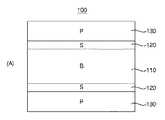
図1は、本発明の好ましい実施形態に係るモアレ縞を有する光学シートの断面図である。図1によれば、モアレ縞を有する光学シート100は透光性基材層110、基板層120およびパターン層130を含む。以下の説明は図1を参照する。一方、以下では便宜上‘モアレ縞(moire fringe)を有する光学シート100’を‘モアレシート100’と略称する。 FIG. 1 is a cross-sectional view of an optical sheet having moire fringes according to a preferred embodiment of the present invention. According to FIG. 1, the
モアレシート100はバックライトアセンブリー(backlight assembly)に備えられる光学シートであり、一つの透光性基材層110、少なくとも二つの基板層120、少なくとも二つのパターン層130を含む。しかし、本実施形態においてモアレシート100の構成が必ずこれに限定されるわけではない。例えば、モアレシート100は少なくとも二つのパターン層130だけで構成され得、両側面にモアレ縞を表出させるための互いに相違するパターンが形成された単一パターン層130だけで構成されることも可能である。 The
透光性基材層110は背面光源をディスプレイパネル側に透過させる基材を含むベースフィルムレイヤ(basefilm layer)である。本実施形態において透光性基材層110はモアレシート100内に単一層で形成され、詳しくは、次の位置に形成される。第1に、二つの基板層120の間にパターン層130がない場合、透光性基材層110は二つの基板層120の間に位置する。図1の(a)においてこのような透光性基材層110の位置を確認できる。第2に、二つの基板層120の間にパターン層130がある場合、透光性基材層110はパターン層130によって囲まれない基板層120の外部露出面に積層位置する。図1の(b)においてこのような透光性基材層110の位置を確認できる。一方、背面光源はディスプレイ装置の画面表示機能のためのものであって、バックライト光源を含む概念であり、ディスプレイパネルはLCDパネルを含む概念である。 The translucent
図1の(a)〜(b)は基板層120とパターン層130が各々2つの場合、透光性基材層110の位置に関するものである。ところが、本実施形態において基板層120とパターン層130はモアレシート100に三つ以上備えられることも可能である。このような場合にも透光性基材層110が上述したとおりに位置され得るが、必ずしもそうする必要はない。 FIGS. 1A and 1B relate to the position of the translucent
透光性基材層110はポリエチレンテレフタレート(PET;Poly−Ethylene Terephthalate)樹脂、ポリカーボネート(PC;Poly−Carbonate)樹脂、ポリメチルメタクリレート(PMMA;poly−methyl methacrylate)樹脂、ポリスチレン(PS;Poly−Styrene)樹脂などの透光性に優れた樹脂のうち少なくとも一つの樹脂を含む。好ましくは、透光性基材層110はPET樹脂を含む。その理由は、PET樹脂が耐熱性と電気的特性に優れ、温度や湿度の影響を少なく受けるのでバックライトアセンブリーに付着する光学シートとして非常に適しているためである。 The
透光性基材層110はパターン層130の間の調和で干渉紋が表出されるように10μm〜2000μmの厚さに形成される。好ましくは、透光性基材層110はモアレシート100全面でモアレ縞が鮮明に表出されるように125μm〜250μmの厚さに形成される。 The translucent
透光性基材層110は10μm〜2000μmの厚さが可能なようにPET原緞に薄膜蒸着過程のITO(Indium Tin Oxide)処理を行いITOフィルム形態に製造することができる。例えば、透光性基材層110はフィルムタイプのPET原緞にITOをスパッタリング(sputtering)方法で蒸着させ、ITOフィルム形態に製造することができる。この場合、透光性基材層110はアンダーコーティング(under coating)処理、インデックスマッチング(index matching)等を考慮して、光線透過率が90%以上でヘイズ(haze)が0.9〜1.2になるように製造するのが好ましい。また、透光性基材層110はPET原緞レイヤとITOレイヤの厚さを減らすか、またはITOレイヤの抵抗値を大きくすることで光線透過率を高めることも可能である。 The
パターン層130は一面にパターンアレイ(pattern array)を形成するパターンアレイレイヤ(pattern array layer)である。前記において、パターンアレイは規則的に(または不規則的に)形成された特定のパターンの集合を意味する。また、パターンが規則的に形成されるということは同一の形状を有するパターンが一定間隔ごとに形成されることを意味する。パターンが規則的に形成されていれば、熱や湿気などの外力による変形に対して均一な挙動によりシート変形のない優れた光学シートを量産することができる。 The
パターン層130はモアレシート100に少なくとも二つ備えられる。モアレシート100においてパターン層130は相互間にチルト(tilt)を形成する。モアレシート100に備えられるパターン層130のうちいずれか一つのパターン層130を第1パターン層といい、他の一つのパターン層130を第2パターン層というと、チルトは第1パターン層に対し第2パターン層がずれた角度を意味する。このようなチルトは第1パターン層のパターンによる一辺と第2パターン層のパターンによる一辺が形成する角度で定義できる。前記において、一辺とは、第1パターン層(または第2パターン層)に備えられる少なくとも二つのパターンを連結する直線を意味する。チルトは第1パターン層の少なくとも二つの辺による一面と第2パターン層の少なくとも二つの辺による一面が形成する角度で定義することも可能である。前者によると、チルトは第1パターン層に備えられるパターンの配列された方向を1次元的に表現する第1方向角と第2パターン層に備えられるパターンの配列された方向を1次元的に表現する第2方向角が互いに相違するということである。また、後者によると、チルトは第1パターン層に備えられるパターンの配列された方向を2次元的に表現する第1方向角と第2パターン層に備えられるパターンの配列された方向を2次元的に表現する第2方向角が互いに相違するということである。パターン層130のこのような構造によりモアレシート100においてはモアレ縞を観察することができる。 At least two pattern layers 130 are provided on the
以下ではモアレシート100がモアレ紋を有するようになった過程について詳細に説明する。図2は、モアレシートのモアレ縞形成過程を説明するための参考図である。以下の説明は図2を参照する。 Hereinafter, the process in which the
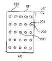
先ず、モアレシート100に第1パターン層131と第2パターン層132が備えられ、第1パターン層131が第2パターン層132より上部面に位置すると仮定する。第1パターン層131と第2パターン層132は図2の(a)に示すように同一のパターンアレイを有する。併せて、第1パターン層131に備えられる1パターンを第1パターン201といい、第2パターン層132に備えられる1パターンを第2パターン202という。 First, it is assumed that the
第2パターン層132の上に第1パターン層131がずれないまま積層されるならば、図2の(b)に示すように上側からながめる場合、第1パターン201と第2パターン202が完全に重複し、第1パターン201だけが見えるだけである。このような場合のモアレシート100はモアレ縞を形成しないか、または無視できるほど非常にかすかなモアレ縞を表出させるだけである。この時、第1パターン層131と第2パターン層132との間のチルトは0°である。 If the
反面、図2の(c)のように第2パターン層132の上に第1パターン層131が所定の角度(ex.チルト値θ°)を形成し、ずれたまま積層されたならば、上側からながめる場合、第1パターン201と第2パターン202が部分重複し、モアレシート100はモアレ縞を鮮明に表出させる。より詳しい説明は図12を参照して後述する。 On the other hand, if the
モアレシート100がモアレ紋を表出させる場合、第1パターン層131と第2パターン層132が形成するチルトは−90°〜+90°である。図2の(d)を参照すると、第1パターン層131を基準として第2パターン層132が時計方向に回転することによってずれている状態ならば、第1パターン層131と第2パターン層132との間のチルトはプラス(+)値を有する。反面、第1パターン層131を基準として第2パターン層132が反時計方向に回転することによってずれている状態ならば、第1パターン層131と第2パターン層132との間のチルトはマイナス(−)値を有する。 When the
以下の説明は図12を参照する。
一般的にモアレ縞は二つ以上の周期的なパターン(periodic pattern)が重なる時に作られる干渉紋(interference fringe)で定義できる。本実施形態においてこのようなモアレ縞はいわゆるビート(beating)現象に基づいて、第1パターン層131に形成されたパターンと第2パターン層132に形成されたパターンが重複する時ごとに両層131,132のパターンを合成させたような新しいパターンに生成される。以下では新しく生成されたパターンをモアレパターンと指し示す。The following description refers to FIG.
In general, moire fringes can be defined by interference fringes created when two or more periodic patterns overlap. In the present embodiment, such moire fringes are based on the so-called beating phenomenon, and the
ところが、モアレ縞は両層131,132で多くの個数のパターンが重なると第1パターン層131と第2パターン層132に形成されているパターンを拡大させたように表出される。図12の(a)を参照すると、両層131,132の共通位置パターン203を固定したままチルト値(α°)を小さくして第1パターン層131に対し第2パターン層132を時計方向に回転させると、両層131,132の大部分のパターンで部分重複現象が発生する。すなわち、両層131,132のパターンの間に干渉が多くなり、図12の(b)のように両層131,132のパターン201,202より大きさがさらに大きいモアレパターン204が生成される。 However, moire fringes appear as if the patterns formed in the
反面、図12の(c)のように、チルト値(β°、β>α)を大きくして第1パターン層131に対し第2パターン層132を時計方向に回転させると両層131,132の一部パターンだけで部分重複現象が発生する。この場合、両層131,132のパターンの間に干渉が少なくなり、図12の(d)のように両層131,132のパターン201,202と大きさがほぼ同一のモアレパターン204が生成される。 On the other hand, when the tilt value (β °, β> α) is increased and the
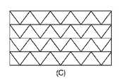
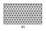
図13〜図15は両層131,132のパターンの形状が各々正三角形、正六角形、正方形、正五角形の時、チルト値によるモアレパターンの大きさの変化に関するものである。以下図13〜図15を参照して説明する。 FIGS. 13 to 15 relate to changes in the size of the moire pattern depending on the tilt value when the patterns of the
図13は第1パターン層と第2パターン層に形成されたパターンの形状が正三角形状または正六角形状の時である。図13において(a)はチルト値によるモアレパターンの大きさの変化を示すグラフである。(a)のように、チルト値が6°の時、モアレパターンの大きさは最大値を有し、チルト値が60°の時、モアレパターンの大きさは最小値を有する。チルト値が60°の時、モアレパターンの大きさが最小値を有するのは、この角度で両層131,132のパターン間の干渉がなくなるためである。一方、チルト値が0°から6°まで増加する時にはモアレパターンの大きさが幾何級数的に大きくなるが、これは両層131,132のパターンの間に干渉が急激に深刻化されるためである。各辺の長さが10μmの正三角形状のパターンまたは正六角形状のパターンが形成された両層131,132を利用して実験する場合、チルト値が2°の時、モアレパターンの大きさは約4mmであり、チルト値が4°の時、モアレパターンの大きさは約12mmである。また、チルト値が6°の時、モアレパターンの大きさは約32mmで最大値を有し、チルト値が60°の時、モアレパターンの大きさは約50μmで最小値を有する。 FIG. 13 shows a case where the shapes of the patterns formed in the first pattern layer and the second pattern layer are regular triangles or regular hexagons. FIG. 13A is a graph showing a change in the size of the moire pattern depending on the tilt value. As in (a), when the tilt value is 6 °, the size of the moire pattern has a maximum value, and when the tilt value is 60 °, the size of the moire pattern has a minimum value. The reason why the size of the moire pattern has the minimum value when the tilt value is 60 ° is that there is no interference between the patterns of both
一方、(b)はパターン形状が正三角形でチルト値が10°の時のモアレパターンを図示したものであり、(c)はパターン形状が正六角形でチルト値が10°の時のモアレパターンを図示したものである。 On the other hand, (b) illustrates the moire pattern when the pattern shape is a regular triangle and the tilt value is 10 °, and (c) illustrates the moire pattern when the pattern shape is a regular hexagon and the tilt value is 10 °. It is illustrated.
図14は第1パターン層と第2パターン層に形成されたパターンの形状が正方形状の時である。図14で(a)はチルト値によるモアレパターンの大きさの変化を示すグラフである。(a)のように、チルト値が6°、84°の時、モアレパターンの大きさは最大値を有し、チルト値が90°の時、モアレパターンの大きさは最小値を有する。各辺の長さが10μmの正方形状のパターンが形成された両層131,132を利用して実験する場合、チルト値が6°、84°の時、モアレパターンの大きさは約35mmで最大値を有し、チルト値が90°の時、モアレパターンの大きさは約70μmで最小値を有する。チルト値が45°の時、モアレパターンの大きさは約17mmである。 FIG. 14 shows a case where the shapes of the patterns formed on the first pattern layer and the second pattern layer are square. FIG. 14A is a graph showing the change in the size of the moire pattern depending on the tilt value. As in (a), when the tilt value is 6 ° and 84 °, the size of the moire pattern has a maximum value, and when the tilt value is 90 °, the size of the moire pattern has a minimum value. When an experiment is performed using both
一方、(b)はパターン形状が正方形でチルト値が10°の時のモアレパターンを図示したもので、(c)はパターン形状が正方形でチルト値が35°の時のモアレパターンを図示したものであり、(d)はパターン形状が正方形でチルト値が45°の時のモアレパターンを図示したものである。 On the other hand, (b) illustrates a moire pattern when the pattern shape is square and the tilt value is 10 °, and (c) illustrates a moire pattern when the pattern shape is square and the tilt value is 35 °. (D) shows a moire pattern when the pattern shape is square and the tilt value is 45 °.
図15は第1パターン層と第2パターン層に形成されたパターンの形状が正五角形状の時である。図15の(a)のように、チルト値が6°、66°、78°の時、モアレパターンの大きさは最大値を有し、チルト値が72°の時、モアレパターンの大きさは最小値を有する。各辺の長さが10μmの正五角形状のパターンが形成された両層131,132を利用して実験する場合、チルト値が6°、66°、78°の時、モアレパターンの大きさは約37mmで最大値を有し、チルト値が72°の時、モアレパターンの大きさは約80μmで最小値を有する。 FIG. 15 shows a case where the shape of the pattern formed on the first pattern layer and the second pattern layer is a regular pentagon. As shown in FIG. 15A, when the tilt value is 6 °, 66 °, and 78 °, the size of the moire pattern has the maximum value, and when the tilt value is 72 °, the size of the moire pattern is Has a minimum value. In an experiment using both
一方、(b)はパターン形状が正五角形でチルト値が5°の時のモアレパターンを図示したものであり、(c)はパターン形状が正五角形でチルト値が40°の時のモアレパターンを図示したものである。 On the other hand, (b) shows a moire pattern when the pattern shape is a regular pentagon and a tilt value is 5 °, and (c) shows a moire pattern when the pattern shape is a regular pentagon and a tilt value is 40 °. It is illustrated.
図16は第1パターン層と第2パターン層に形成されたパターンの形状が円形状の時のチルト値によるモアレパターンの大きさの変化を見せる図である。(a)を参照すると、チルト値が2°の時、モアレパターンの大きさは約4mmである。また、(b)を参照すると、チルト値が4°の時、モアレパターンの大きさは約12mmである。また、(c)を参照すると、チルト値が6°の時、モアレパターンの大きさは約32mmである。(a)〜(c)のように、チルト値が0°〜6°の時、モアレパターンの大きさが急激に変化することが分かる。 FIG. 16 is a diagram showing a change in the size of the moire pattern depending on the tilt value when the shapes of the patterns formed in the first pattern layer and the second pattern layer are circular. Referring to (a), when the tilt value is 2 °, the size of the moire pattern is about 4 mm. Referring to (b), when the tilt value is 4 °, the size of the moire pattern is about 12 mm. Referring to (c), when the tilt value is 6 °, the size of the moire pattern is about 32 mm. As shown in (a) to (c), it can be seen that when the tilt value is 0 ° to 6 °, the size of the moire pattern changes abruptly.
再び図1を参照して説明する。
パターン層130は一面を通して基板層120と接着する。しかし、すべてのパターン層130が必ずしも基板層120と接着する必要はない。本実施形態においては最小限二つのパターン層130が基板層120と接着したまま共にモアレシート100に備えられれば、モアレ縞を鮮明に表出させることができる。A description will be given with reference to FIG. 1 again.
The
パターン層130は基板層120に容易に接着できるように接着力に優れた接着剤成分を含む。本実施形態においてパターン層130は接着剤成分としてエポキシ系、尿素系、メラミン系、フェノール系、不飽和ポリエステル系、レゾルシノール系などの熱硬化性樹脂成分や、アクリル系、ウレタン系、酢酸ビニル系、ポリビニルアルコール系、塩化ビニル系、ポリビニルアセタール系、飽和ポリエステル系、ポリアミド系、ポリエチレン系などの熱可塑性樹脂成分を含む。好ましくは、パターン層130は接着剤成分としてエポキシ系樹脂、ウレタン系樹脂、アクリル系樹脂などを含む。その理由はエポキシ系樹脂、ウレタン系樹脂、アクリル系樹脂などが他の樹脂に比べて接着力に優れ、反応時、副生成物がないためである。また、加工が容易なだけでなく、容易に入手でき、価格が安価な長所もある。 The
パターン層130が接着剤成分としてエポキシ系樹脂やウレタン系樹脂を含む場合、エポキシ系接着剤、ウレタン系接着剤などを含むことが好ましい。エポキシ系接着剤はエポキシ系樹脂の他に硬化剤、充填剤、希釈剤、その他の添加剤などをさらに含むことによって硬化時間や粘度などを調節でき、単価を節減し、機能性もさらに向上させることができる。ウレタン系接着剤もウレタン系樹脂の他にジイソシアネート(diisocyanate)、鎖延長剤、溶剤、その他の添加剤などをさらに含むことによって内衝撃性を強化し、柔軟性を向上させることができる。 When the
パターン層130は接着剤成分としてUV(Ultra−Violet)硬化型接着剤を含むことも可能である。UV硬化型接着剤はエポキシ樹脂やウレタン樹脂などをオリゴマー(oligomer)として含むものであり、有機溶剤を使わないため無公害であり、短時間で接着可能である。また、低温でも硬化し、接着力に非常に優れており、コーティング効果も得ることができる。 The
一方、パターン層130は接着剤成分としてビニル系、フェノール−クロロプレンゴム系、ポリアミド系、ニトリルゴム−エポキシ系などの混合系樹脂成分や、デンプン、デキストリン、にかわ、カゼイン、ラテックス、ゴム糊、松脂、セラックなどの天然樹脂成分を含むことも可能である。 On the other hand, the
パターン層130は統一されたパターンの幅と深さを考慮して、500μm以下の厚さに形成される。好ましくは、パターン層130はモアレ紋が鮮明に表出されるように0.5μm〜100μmの厚さに形成される。 The
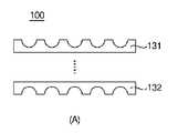
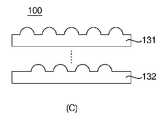
パターン層130がモアレシート100に少なくとも二つ備えられることはすでに説明した。以下ではモアレシート100に二つのパターン層130が備えられることを考慮して、それぞれのパターン層が有するパターン形態について説明する。図3〜4はモアレシートに備えられるそれぞれのパターン層が有するパターン形態を説明するための参考図である。詳しくは、図3は、モアレシート100が図1の(a)構造による場合の第1パターン層131と第2パターン層132が形成するパターン形態に関するものであり、図4は、モアレシート100が図1の(b)構造による場合の第1パターン層131と第2パターン層132が形成するパターン形態に関するものである。以下の説明は図3〜4を参照する。 As described above, at least two pattern layers 130 are provided on the
先ず図3を参照すると、二つのパターン層130の間に透光性基材層110がある場合、第1パターン層131と第2パターン層132が各々陽核パターンアレイと陰核パターンアレイのうちいずれのパターンアレイを有するか否かにより4種類のタイプが可能である。具体的に説明すると、図3(a)に示された第1タイプは、第1パターン層131と第2パターン層132のいずれも陰核パターンアレイを有する場合であり、図3(b)に示された第2タイプは、第1パターン層131と第2パターン層132のいずれも陽核パターンアレイを有する場合である。図3(c)に示された第3タイプは、第1パターン層131が陽核パターンアレイを有して、第2パターン層132が陰核パターンアレイを有する場合であり、図3(d)に示された第4タイプは、第1パターン層131が陰核パターンアレイを有して第2パターン層132が陽核パターンアレイを有する場合である。第1タイプ〜第4タイプにおいて第1パターン層131の形態はモアレシート100の上側に位置した視覚を考慮したものであり、第2パターン層131の形態はモアレシート100の下側に位置した視覚を考慮したものである。 First, referring to FIG. 3, when the
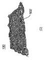
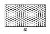
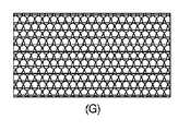
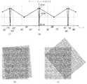
図5の(a)〜(b)が陽核パターンアレイを備えるパターン層130の実際の具現例であり、図5の(c)〜(d)が陰核パターンアレイを備えるパターン層130の実際の具現例である。図5(a)〜(b)において図面符号501が陽核パターンであり、図5(c)〜(d)において図面符号502が陰核パターンである。 FIGS. 5A to 5B are actual implementation examples of the
実験例を挙げて後述するが、ヘイズ(haze)数値、拡散光(D;Diffusion of transmitted light)透過率(または散乱光透過率)、全透過光(T;Total transmitted light)透過率、平行光(P;Parallel of transmitted light)透過率(または透過光透過率)等のスペック(specification)を考慮する場合、第1タイプ〜第4タイプは従来の光学シートよりすべてのスペックの側面でさらに優れている。その理由は光の進行方向を考慮する時、第1パターン層131と第2パターン層132のうち少なくとも一つのパターン層のパターンアレイが光を全方向にまんべんなく散乱させるためである。それぞれのタイプはその特性において微細な差があるため、ユーザに応じて多様に選択されて使用され、ディスプレイモジュールの特性を変更することができる。 As will be described later with reference to experimental examples, haze numerical values, diffused light (D) transmission (or scattered light transmittance), total transmitted light (T) transmittance, parallel light (P: Parallel of transmitted light) When considering specifications such as transmittance (or transmitted light transmittance), the first type to the fourth type are more excellent in terms of all specs than the conventional optical sheet. Yes. The reason is that when considering the light traveling direction, the pattern array of at least one of the
次に図4を参照すると、前記と同じように二つのパターン層130の間に透光性基材層110がない場合も第1パターン層131と第2パターン層132が各々陽核パターンアレイと陰核パターンアレイのうちいずれのパターンアレイを有するか否かにより4種類のタイプが可能である。具体的に説明すると、図4(a)に示された第5タイプは、第1パターン層131が陰核パターンアレイを有して第2パターン層132が陽核パターンアレイを有する場合であり、図4(b)に示された第6タイプは、第1パターン層131が陽核パターンアレイを有して第2パターン層132が陰核パターンアレイを有する場合である。図4(c)に示された第7タイプは、第1パターン層131と第2パターン層132のいずれも陽核パターンアレイを有する場合であり、図4(d)に示された第8タイプは第1パターン層131と第2パターン層132のいずれも陰核パターンアレイを有する場合である。第5タイプ〜第8タイプにおいて第1パターン層131と第2パターン層132の形態はモアレシート100の上側に位置した視覚を考慮したものである。 Next, referring to FIG. 4, the
これもまた実験例を挙げて後述するが、ヘイズ数値、拡散光透過率、全透過光透過率、平行光透過率などのスペックを考慮する場合、第5タイプ〜第8タイプは従来の光学シートよりすべてのスペックの側面でさらに優れている。第5タイプ〜第8タイプのように二つのパターン層131,132が接近した場合には陽核パターンアレイと陰核パターンアレイが調和をなすことが最も効果的に光を全方向にまんべんなく散乱させることができる。図4(a)に示すように第1パターン層131の1パターン401と第2パターン層132の1パターン402をつなぐ直線がモアレシート100に対して有する傾斜角(α)が1°〜89°の時、光をさらに効果的に全方向にまんべんなく散乱させることができる。 Although this will also be described later with reference to experimental examples, when considering specifications such as haze numerical value, diffuse light transmittance, total transmitted light transmittance, parallel light transmittance, the fifth type to the eighth type are conventional optical sheets. Even better in terms of all specs. When the two pattern layers 131 and 132 are close to each other as in the fifth type to the eighth type, it is most effective to harmonize the nuclei pattern array and the clitoral pattern array so that light is scattered evenly in all directions. be able to. As shown in FIG. 4A, the inclination angle (α) of the straight line connecting one
図3〜4を参照して、上述したことは、第1パターン層131の1パターンと第2パターン層132の1パターンが同一の大きさを有する場合に関することである。本実施形態において第1パターン層131の1パターンと第2パターン層132の1パターンは必ずしも同一の大きさを有する必要はない。すなわち、第1パターン層131の1パターンと第2パターン層132の1パターンは互いに相違する大きさを有することも可能である。 3 to 4 described above relates to the case where one pattern of the
パターン層130に形成される各パターンの形状は図3〜4に示すように半球状であることが通常である。しかし、本実施形態において必ずしもここで限定される必要はなく、図6の(a)〜(g)に示すように各パターンの形状はその切断面が多角形状、円形状、楕円形状などであるか、菱形状、平行四辺形状などであることも可能である。また、パターンの形状はファロウ(furrow)プリズム状も可能である。以上のパターン形状は陽核パターンだけでなく陰核パターンにも適用される。 The shape of each pattern formed on the
パターン層130には同一のパターンが反復的に形成され、このようなパターンをまとめてパターンアレイと称することはすでに説明した。しかし、本実施形態において必ずしもここで限定される必要はなく、各パターン層130には各々他の形状を有するパターンが形成されることも可能である。例えば、一つのパターン層130に半球状の第1パターン、四角形状の第2パターン、菱形状の第3パターンなどが調和をなし形成されることも可能である。 As described above, the same pattern is repeatedly formed on the
再び図1を参照して説明する。
基板層120はパターン層130の一側面に接合する。したがって、モアレシート100において基板層120はパターン層130と同数個備えられる。本実施形態において基板層120は透光性基材層110とパターン層130との間または隣接する二つのパターン層130の間に形成される。A description will be given with reference to FIG. 1 again.
The
基板層120は接着力を考慮して、パターン層130と同一の素材で形成される。しかし、必ずしもここで限定される必要はなく、基板層120がパターン層130より接着力がさらに優れた素材で形成されるか、または粘着剤成分を含んで形成されることも可能である。 The
基板層120は隣接する二つのパターン層130の間の間隔または透光性基材層110とパターン層130の間の間隔を調整するために100μm以下の厚さに形成される。好ましくは、基板層120は前記間隔調整によりモアレ縞が鮮明に表出されるように0.1μm〜10μmの厚さに形成される。 The
基板層120の厚さはモアレシート100に備えられるパターン層130の厚さや個数により任意変更され得る。本実施形態においては基板層120の厚さ値がパターン層130の厚さ値の0.1%〜50%であることが好ましい。その理由はこのような基板層120を備えるモアレシート100が全面でモアレ縞を鮮明に表出させるためである。 The thickness of the
一方、上述したように、パターン層130は陽核パターンアレイまたは陰核パターンアレイを備えることができる。また、モアレシート100は少なくとも一つのパターン層130だけで構成することができる。したがって、陽核パターンアレイが各々形成された二つのパターン層でモアレシートを構成する場合には、この二つのパターン層の間に所定の厚さの空気層がさらに付加され得る。 On the other hand, as described above, the
以下においてはモアレシート100がモアレ紋を形成することによって得た利点について説明する。
LCDはパネル裏面のBLU(Back−Light Unit)から出た光がパネルを通過し色を帯びるようになる原理で駆動される。BLUが発現できる光量が大きいほどLCD画面がさらに明るくなるため、LCD業者では2種類の方法を通してBLUの光量を改善している。第1の方法は光を出す光源の性能を改善させるか、または光源の個数を増やして光量を増加させる方法である。そして、第2の方法は拡散シート、プリズムシートなどの光学フィルムを利用して浪費される光を最小化する方法である。Hereinafter, advantages obtained by forming the moire pattern on the
The LCD is driven on the principle that light emitted from a BLU (Back-Light Unit) on the back side of the panel passes through the panel and becomes colored. As the amount of light that can be expressed by the BLU increases, the LCD screen becomes brighter. Therefore, LCD manufacturers improve the amount of light of the BLU through two methods. The first method is to improve the performance of a light source that emits light, or to increase the amount of light by increasing the number of light sources. The second method is a method of minimizing wasted light using an optical film such as a diffusion sheet or a prism sheet.
BLUの光量を決める最も大きな要因は光源である。現在、大部分のBLUは蛍光灯の一種であるCCFL(Cold Cathode Flourscent Lamp;冷陰極蛍光ランプ)を光源として利用しており、最近ではEEFL(External Electrode Flourscent Lamp;外部電極蛍光ランプ)、LEDなどが光源として次第に拡大利用されている。ところが、このような光源はBLUに多く装着されるほど大きな光量を出すことができる。しかし、光源の個数を増やせば製造原価が上昇し、電力消耗量も光源の個数に比例して増加する問題点が発生する。そこで、最近では、第2の方法を利用してBLUの光量を増加させることが一般である。 The biggest factor that determines the amount of BLU light is the light source. At present, most BLUs use CCFL (Cold Cathode Fluorescent Lamp) which is a kind of fluorescent lamp as a light source, and recently EEFL (External Electrode Fluorescent Lamp), LED, etc. Is increasingly used as a light source. However, such a light source can emit a larger amount of light as it is mounted more on the BLU. However, if the number of light sources is increased, the manufacturing cost increases and the amount of power consumption increases in proportion to the number of light sources. Therefore, recently, it is common to increase the amount of BLU light using the second method.
第2の方法は光学フィルムを用いる方法である。光源から出た光はすべての方向に発散されるため、光源だけでLCDパネルを駆動する場合、一部の光だけが画面の具現に利用される。光学フィルムは屈折/反射を通して、光の方向を全面に向くようにして浪費される光を最小化し、画面を明るくする役割をする。LCD BLUには反射シート、拡散シート、プリズムシート(BEF;Brightness Enhancement Film)、レンズパターン複合シート、このうち輝度向上フィルム(DBEF;Dual Brightness Enhancement Film)等、多様な光学フィルムが使われ、光の輝度を高める機能をする。 The second method is a method using an optical film. Since the light emitted from the light source is diverged in all directions, when driving the LCD panel with only the light source, only a part of the light is used for realizing the screen. The optical film serves to lighten the screen by minimizing wasted light through refraction / reflection and directing the light to the entire surface. The LCD BLU uses a variety of optical films such as a reflection sheet, a diffusion sheet, a prism sheet (BEF), a lens pattern composite sheet, a brightness enhancement film (DBEF), and a variety of optical films such as a light-enhancement film. Function to increase brightness.
本実施形態に係るモアレシートはパターン層ごとに大きさや模様が考慮されたパターンを規則的に配列させて、パターン層の間にはチルトを調節することによってモアレ現象を用いた干渉紋をパターン化させた。このようなモアレシートは輝度、視野角、隠蔽力、拡散機能など、多様な光学的性能を従来の光学フィルムよりさらに向上させた。 The moire sheet according to the present embodiment regularly arranges patterns in consideration of size and pattern for each pattern layer, and patterns interference patterns using the moire phenomenon by adjusting the tilt between the pattern layers. I let you. Such a moire sheet has various optical performances such as brightness, viewing angle, hiding power, diffusion function and the like improved further than the conventional optical film.
詳しくは、モアレシートは陽核パターンアレイが形成されたパターン層と陰核パターンアレイが形成されたパターン層を通して、点光源または線光源で面光源に転換する時に拡散機能と集光機能を同時に行わせることによって、ランプ輝線の輝度をさらに高めて導光板(または拡散板)パターンによる隠蔽現象を除去させる。また、モアレシートはバックライトアセンブリーを設計する時にパターンの大きさや模様、チルト値、シートデザインなどを任意変更させることによって光源が効果的に組合わさり、光度などのバックライトアセンブリーの光特性をさらに向上させる。 Specifically, the moire sheet simultaneously performs a diffusion function and a light collecting function when it is converted to a surface light source with a point light source or a line light source through a pattern layer formed with a positive nucleus pattern array and a pattern layer formed with a clitoral pattern array. As a result, the brightness of the lamp emission line is further increased to eliminate the concealment phenomenon caused by the light guide plate (or diffuser plate) pattern. In addition, when designing a backlight assembly, moire sheets can be combined with light sources effectively by arbitrarily changing the pattern size, pattern, tilt value, sheet design, etc. Further improve.
また、モアレシートは配列と結合の均一度(uniformity)が高いため、熱や湿気などの外力による変形に対して微視的観点で優れた寸法安定性を現わす。また、モアレシートは透光性基材層を中心にその上下にパターン層が備えられる。このようなモアレシートはパターン層が透光性基材層を支持することによって上下両側に偏心を分散させるため、外力による変形に対して巨視的観点でシート変形がない優れた光学シートを量産することができる。 Further, since the moire sheet has a high uniformity of alignment and bonding, it exhibits excellent dimensional stability from a microscopic viewpoint against deformation caused by external force such as heat and moisture. Further, the moire sheet is provided with a pattern layer on the upper and lower sides of the translucent substrate layer. Since such a moire sheet disperses the eccentricity on both the upper and lower sides by supporting the translucent base material layer, the mass production of an excellent optical sheet having no sheet deformation from a macroscopic viewpoint against deformation caused by an external force. be able to.
また、LED光源を有するバックライトユニット(BLU)においてモアレシートは陽核パターンアレイが形成されたパターン層と陰核パターンアレイが形成されたパターン層を通してLED光源の特徴である点形態の光を適切に分散または集光させることによって明部(LED光源の部分)と暗部(LEDとLEDの間の部分)を効果的に除去させ、LEDを過度に使うことによってもたらされるLED発光による高熱現象も防止する。また、LED光源個数の増加により製造原価が上昇するのを防止でき、ディスプレイ装置の重さも減らすことができる。LED光源が搭載されたバックライトユニットにモアレシートを適用させると、LED光源の個数を最小化させる効果も得ることができる。 In addition, in a backlight unit (BLU) having an LED light source, the moire sheet appropriately applies light in a point form that is a feature of the LED light source through a pattern layer on which a positive nucleus pattern array is formed and a pattern layer on which a climatic pattern array is formed. By effectively dispersing or condensing the light, the bright part (LED light source part) and dark part (between the LED and LED) are effectively removed, and the high heat phenomenon caused by LED emission caused by excessive use of the LED is also prevented. To do. Further, it is possible to prevent an increase in manufacturing cost due to an increase in the number of LED light sources, and to reduce the weight of the display device. When a moire sheet is applied to a backlight unit on which an LED light source is mounted, an effect of minimizing the number of LED light sources can be obtained.
一方、モアレシート100は単位面積当たりのパターンの密集度が高いパターン層130を多く備えるほどモアレ縞がきちんと表出され、これによって輝度、視野角などの光学的性能がさらに向上する。本実施形態においてパターンの大きさを考慮する時、1cm2単位面積に10〜6000個のパターンが密集している時、モアレシート100全面でモアレ縞が鮮明に表出される。On the other hand, the more the
一方、モアレシート100においてモアレ縞が鮮明に表出されるようにするためには、最上位層がパターン層130であることが好ましい。 On the other hand, it is preferable that the uppermost layer is the
次に、パターン層のそれぞれのパターン形態によるモアレシートの1実施形態を説明する。パターン層のパターン形態は第1タイプ〜第8タイプがあり、図3〜4を参照して、上述した。 Next, an embodiment of a moire sheet according to each pattern form of the pattern layer will be described. The pattern form of the pattern layer includes the first type to the eighth type, and has been described above with reference to FIGS.
(1)パターン層のパターン形態が第7タイプのモアレシート
製造されたバックライトアセンブリー用光学シートの仕様は次の通りである。125μmの厚さのPETからなる少なくとも一つの透光性基材上部に紫外線(UV)硬化型アクリル系材質のパターンアレイ(マイクロレンズアレイ、MLA)が2つ積層されている。それぞれのマイクロレンズアレイは5±1μmの厚さの基底層と38±1μmの厚さのパターン層で構成されており、それぞれのマイクロレンズアレイ内のマイクロレンズは半球型形状に一定の大きさおよび間隔で配列され、規則的なパターンを形成する。一つのパターンアレイと他の一つのパターンアレイのチルトは+75°の角度をなし、前記二つのパターンアレイは(+)パターンからなる下部パターン(bottom pattern)のパターンアレイと(+)パターンからなる上部パターン(top pattern)のパターンアレイで構成されている。ここで(+)パターンは陽核パターンを指示し、(−)パターンは陰核パターンを指し示す。(1) The pattern form of the pattern layer is a seventh type moire sheet The specifications of the manufactured optical sheet for the backlight assembly are as follows. Two pattern arrays (micro lens array, MLA) of ultraviolet (UV) curable acrylic material are laminated on at least one translucent substrate made of PET having a thickness of 125 μm. Each microlens array is composed of a base layer having a thickness of 5 ± 1 μm and a pattern layer having a thickness of 38 ± 1 μm, and the microlens in each microlens array has a certain size and a hemispherical shape. Arranged at intervals to form a regular pattern. The tilt between one pattern array and another pattern array forms an angle of + 75 °, and the two pattern arrays are a (+) pattern lower pattern (bottom pattern) pattern array and an (+) pattern upper portion. It consists of a pattern array of patterns (top pattern). Here, the (+) pattern indicates a positive nucleus pattern, and the (−) pattern indicates a clitoral pattern.
正面輝度と視野角を測定するための実験条件は次の通りである。
バックライトユニットの大きさ:17’、測定装備:BM−7輝度色彩系、入力電圧:12V、測定範囲:−80°〜+80°、測定間隔:10秒、ランプ:2ea。The experimental conditions for measuring the front luminance and viewing angle are as follows.
Backlight unit size: 17 ', measurement equipment: BM-7 luminance color system, input voltage: 12V, measurement range: -80 ° to + 80 °, measurement interval: 10 seconds, lamp: 2ea.
前記のような条件下で正面輝度と視野角を測定した結果、−44°〜+43°(半値角:87°)範囲で正面輝度は一般の拡散シート対比108.0%であり、視野角は約1400〜2900であった。 As a result of measuring the front luminance and the viewing angle under the conditions as described above, the front luminance in the range of −44 ° to + 43 ° (half-value angle: 87 °) is 108.0% compared to a general diffusion sheet, and the viewing angle is It was about 1400-2900.
また、濁度(haze)、拡散光(D;Diffusion of transmitted light)、全透過光(T;Total transmitted light)、平行光(P;Parallel of transmitted light)等を測定するための実験条件は次の通りである。
入力電圧:12V、ランプ電流:6.5mA、温度:21℃、湿度:40%。In addition, turbidity (h), diffused light (D; Diffusion of transmitted light), total transmitted light (T; Total transmitted light), parallel light (P; Parallel of transmitted light), etc. are used to measure the following conditions. It is as follows.
Input voltage: 12 V, lamp current: 6.5 mA, temperature: 21 ° C., humidity: 40%.
前記のような条件下で濁度測定機を利用して、濁度、拡散光、全透過光、平行光などを測定した結果、濁度は77.41%であり、全透過光の波長は51.95nmであり、拡散光の波長は40.21nmであり、平行光の波長は11.74nmであった。 As a result of measuring turbidity, diffused light, total transmitted light, parallel light, etc. using a turbidity measuring machine under the above conditions, the turbidity is 77.41%, and the wavelength of the total transmitted light is It was 51.95 nm, the wavelength of diffused light was 40.21 nm, and the wavelength of parallel light was 11.74 nm.
濁度測定機はすべての実施形態においてNippon Denshoku Kogyoで市販する濁度計(turbidimeter)(一連番号:COH300、NDH300A、NDH5000等)を利用した。このような濁度測定機の原理は次の通りである。 A turbidimeter (turbidimeter) (series number: COH300, NDH300A, NDH5000, etc.) commercially available from Nippon Denshoku Kogyo was used in all the embodiments. The principle of such a turbidity measuring machine is as follows.
ランプから出た光がサンプル(透明または半透明)を透過して、サンプルを通過した光は積分球内に入射する。この時、光はサンプルによって拡散光と平行光が分離され、これらの光は積分球内に反射して受光素子に集光するようになる。その理由は、積分球内に硫酸バリウムという物質があり、すべての光を反射するためである。光の量を電子信号に変える素子の受光素子によって、集光された光は計測部に伝達して、所望の測定データがディスプレイに出力される。また、測定光を計算する方法は回転モータによるが、モータの回転は測定時に常に維持される。回転モータの一方は光を反射させ、他方は光の通過によって、平行光と透過光を分離させる。濁度(%)は‘[拡散光の波長(nm)/全透過光の波長(nm)]×100’公式から求め、平行光の波長(nm)は‘全透過光の波長(nm)−拡散光(DT)の波長(nm)’公式から求める。 The light emitted from the lamp passes through the sample (transparent or translucent), and the light passing through the sample enters the integrating sphere. At this time, the diffused light and the parallel light are separated from each other by the sample, and these lights are reflected in the integrating sphere and are collected on the light receiving element. The reason is that there is a substance called barium sulfate in the integrating sphere, which reflects all the light. The collected light is transmitted to the measuring unit by the light receiving element that changes the amount of light into an electronic signal, and desired measurement data is output to the display. The method for calculating the measurement light is based on a rotary motor, but the rotation of the motor is always maintained during measurement. One of the rotary motors reflects light, and the other separates parallel light and transmitted light by the passage of light. The turbidity (%) is obtained from the formula of “[diffuse light wavelength (nm) / total transmitted light wavelength (nm)] × 100”, and the parallel light wavelength (nm) is “total transmitted light wavelength (nm) −”. It is obtained from the wavelength (nm) ′ formula of diffused light (DT).
(2)パターン層のパターン形態が第8タイプのモアレシート
製造されたバックライトアセンブリー用光学シートの仕様は次の通りである。一つのパターンアレイ(マイクロレンズアレイ)と他の一つのパターンアレイ(マイクロレンズアレイ)のチルトが−60°の角度をなす。マイクロレンズの大きさが前記(1)の場合に比べて大きい。その他のことは前記(1)と同一である。(2) The pattern form of the pattern layer is the eighth type moire sheet The specifications of the manufactured optical sheet for the backlight assembly are as follows. The tilt between one pattern array (microlens array) and another pattern array (microlens array) forms an angle of −60 °. The size of the microlens is larger than that in the case (1). Others are the same as (1) above.
(1)と同一の実験条件下で正面輝度と視野角を測定した結果、−44°〜+43°(半値角:87°)範囲で正面輝度は一般の拡散シート対比108.4%であり、視野角は約1600〜2600であった。 As a result of measuring the front luminance and the viewing angle under the same experimental conditions as (1), the front luminance in the range of −44 ° to + 43 ° (half-value angle: 87 °) is 108.4% compared to a general diffusion sheet, The viewing angle was about 1600-2600.
同じように、(1)と同一の実験条件下で濁度測定機を利用して、濁度、拡散光、全透過光、平行光などを測定した結果、濁度は77.23%であり、全透過光の波長は51.98nmであり、拡散光の波長は40.14nmであり、平行光の波長は11.84nmであった。 Similarly, as a result of measuring turbidity, diffused light, total transmitted light, parallel light, etc. using a turbidity measuring machine under the same experimental conditions as in (1), the turbidity is 77.23%. The wavelength of the totally transmitted light was 51.98 nm, the wavelength of the diffused light was 40.14 nm, and the wavelength of the parallel light was 11.84 nm.
(3)パターン層のパターン形態が第3タイプのモアレシート
製造されたバックライトアセンブリー用光学シートの仕様は次の通りである。少なくとも一つの透光性基材下部に(−)パターンからなる下部パターン(bottom pattern)のパターンアレイ(マイクロレンズアレイ)が積層されており、前記透光性基材上部に(+)パターンからなる上部パターン(top pattern)のパターンアレイ(マイクロレンズアレイ)が積層されている。一つのパターンアレイと他の一つのパターンアレイのチルトが+90°の角度をなしている。その他のことは前記(1)と同一である。(3) The pattern form of the pattern layer is the third type moire sheet The specifications of the manufactured optical sheet for the backlight assembly are as follows. A pattern pattern (microlens array) of a bottom pattern (bottom pattern) composed of a (−) pattern is laminated on at least one translucent base material, and comprises a (+) pattern on the translucent base material. A pattern array (microlens array) of an upper pattern (top pattern) is stacked. The tilt between one pattern array and another pattern array forms an angle of + 90 °. Others are the same as (1) above.
(1)と同一の実験条件下で正面輝度と視野角を測定した結果、−53°〜+52°(半値角:105°)範囲で正面輝度は一般の拡散シート対比111.9%であり、視野角は約2000〜3000であった。 As a result of measuring the front luminance and the viewing angle under the same experimental conditions as (1), the front luminance in the range of −53 ° to + 52 ° (half-value angle: 105 °) is 111.9% compared to a general diffusion sheet, The viewing angle was about 2000 to 3000.
同じように、(1)と同一の実験条件下で濁度測定機を利用して濁度、拡散光、全透過光、平行光などを測定した結果、濁度は88.21%であり、全透過光の波長は60.53nmであり、拡散光の波長は53.39nmであり、平行光の波長は7.14nmであった。 Similarly, as a result of measuring turbidity, diffused light, total transmitted light, parallel light, etc. using a turbidity measuring machine under the same experimental conditions as in (1), the turbidity is 88.21%, The wavelength of total transmitted light was 60.53 nm, the wavelength of diffused light was 53.39 nm, and the wavelength of parallel light was 7.14 nm.
(4)パターン層のパターン形態が第4タイプのモアレシート
製造されたバックライトアセンブリー用光学シートの仕様は次の通りである。少なくとも一つの透光性基材下部に(−)パターンからなる下部パターン(bottom pattern)のパターンアレイ(マイクロレンズアレイ)が積層されていて、前記透光性基材上部に(+)パターンからなる上部パターン(top pattern)のパターンアレイ(マイクロレンズアレイ)が積層されている。一つのパターンアレイと他の一つのパターンアレイのチルトが+60°の角度をなしており、マイクロレンズの大きさが前記(3)の場合よりさらに大きい。その他のことは前記(1)と同一である。(4) The pattern form of the pattern layer is the fourth type moire sheet The specifications of the manufactured optical sheet for the backlight assembly are as follows. A pattern array (microlens array) of a bottom pattern (bottom pattern) composed of a (−) pattern is laminated on at least one translucent base material, and comprises a (+) pattern on the translucent base material. A pattern array (microlens array) of an upper pattern (top pattern) is stacked. The tilt between one pattern array and another pattern array forms an angle of + 60 °, and the size of the microlens is larger than in the case of (3). Others are the same as (1) above.
(1)と同一の実験条件下で正面輝度と視野角を測定した結果、−53°〜+52°(半値角:105°)範囲で正面輝度は一般の拡散シート対比103.8%であり、視野角は約1600〜2820であった。 As a result of measuring the front luminance and the viewing angle under the same experimental conditions as (1), the front luminance in the range of −53 ° to + 52 ° (half-value angle: 105 °) is 103.8% compared to a general diffusion sheet, The viewing angle was about 1600-2820.
同じように、(1)と同一の実験条件下で濁度測定機を利用して濁度、拡散光、全透過光、平行光などを測定した結果、濁度は88.53%であり、全透過光の波長は76.09nmであり、拡散光の波長は67.36nmであり、平行光の波長は8.73nmであった。 Similarly, as a result of measuring turbidity, diffuse light, total transmitted light, parallel light, etc. using a turbidity measuring machine under the same experimental conditions as in (1), the turbidity is 88.53%, The wavelength of total transmitted light was 76.09 nm, the wavelength of diffused light was 67.36 nm, and the wavelength of parallel light was 8.73 nm.
(5)パターン層のパターン形態が第2タイプのモアレシート
製造されたバックライトアセンブリー用光学シートの仕様は次の通りである。少なくとも一つの透光性基材下部に(+)パターンからなる下部パターン(bottom pattern)のパターンアレイ(マイクロレンズアレイ)が積層されていて、前記透光性基材上部に(+)パターンからなる上部パターン(top pattern)のパターンアレイ(マイクロレンズアレイ)が積層されている。一つのパターンアレイと他の一つのパターンアレイのチルトが+90°の角度をなしている。その他のことは前記(1)と同一である。(5) Moire sheet in which the pattern form of the pattern layer is the second type The specifications of the manufactured optical sheet for the backlight assembly are as follows. A pattern array (microlens array) of a bottom pattern (bottom pattern) composed of a (+) pattern is stacked on at least one translucent substrate, and the (+) pattern is formed on the translucent substrate. A pattern array (microlens array) of an upper pattern (top pattern) is stacked. The tilt between one pattern array and another pattern array forms an angle of + 90 °. Others are the same as (1) above.
(1)と同一の実験条件下で正面輝度と視野角を測定した結果、−53.5°〜+52°(半値角:105.5°)範囲で正面輝度は一般の拡散シート対比107.8%であり、視野角は約2200〜2970であった。 As a result of measuring the front luminance and the viewing angle under the same experimental conditions as in (1), the front luminance in the range of −53.5 ° to + 52 ° (half-value angle: 105.5 °) is 107.8 compared with a general diffusion sheet. %, And the viewing angle was about 2200-2970.
同じように、(1)と同一の実験条件下で濁度測定機を利用して濁度、拡散光、全透過光、平行光などを測定した結果、濁度は88.55%であり、全透過光の波長は63.34nmであり、拡散光の波長は56.09nmであり、平行光の波長は7.25nmであった。 Similarly, as a result of measuring turbidity, diffused light, total transmitted light, parallel light, etc. using a turbidity measuring machine under the same experimental conditions as in (1), the turbidity is 88.55%, The wavelength of all transmitted light was 63.34 nm, the wavelength of diffused light was 56.09 nm, and the wavelength of parallel light was 7.25 nm.
(6)パターン層のパターン形態が第1タイプのモアレシート
製造されたバックライトアセンブリー用光学シートの仕様は次の通りである。少なくとも一つの透光性基材下部に(+)パターンからなる下部パターン(bottom pattern)のパターンアレイ(マイクロレンズアレイ)が積層されていて、前記透光性基材上部に(+)パターンからなる上部パターン(top pattern)のパターンアレイ(マイクロレンズアレイ)が積層されている。一つのパターンアレイと他の一つのパターンアレイのチルトが+60°の角度をなしている。マイクロレンズの大きさは前記(5)の場合より大きい。その他のことは前記(1)と同一である。(6) The pattern form of the pattern layer is the first type moire sheet The specifications of the manufactured optical sheet for the backlight assembly are as follows. A pattern array (microlens array) of a bottom pattern (bottom pattern) composed of a (+) pattern is stacked on at least one translucent substrate, and the (+) pattern is formed on the translucent substrate. A pattern array (microlens array) of an upper pattern (top pattern) is stacked. The tilt of one pattern array and another pattern array forms an angle of + 60 °. The size of the microlens is larger than in the case (5). Others are the same as (1) above.
(1)と同一の実験条件下で正面輝度と視野角を測定した結果、−53.5°〜+52.5°(半値角:106°)範囲で正面輝度は一般の拡散シート対比107.9%であり、視野角は約2200〜2970であった。 As a result of measuring the front luminance and the viewing angle under the same experimental conditions as in (1), the front luminance in the range of −53.5 ° to + 52.5 ° (half-value angle: 106 °) is 107.9 compared with a general diffusion sheet. %, And the viewing angle was about 2200-2970.
同じように、(1)と同一の実験条件下で濁度測定機を利用して濁度、拡散光、全透過光、平行光などを測定した結果、濁度は88.64%であり、全透過光の波長は63.36nmであり、拡散光の波長は56.06nmであり、平行光の波長は7.30nmであった。 Similarly, as a result of measuring turbidity, diffused light, total transmitted light, parallel light, etc. using a turbidity measuring machine under the same experimental conditions as in (1), the turbidity is 88.64%, The wavelength of all transmitted light was 63.36 nm, the wavelength of diffused light was 56.06 nm, and the wavelength of parallel light was 7.30 nm.
(7)パターン層のパターン形態が第5タイプのモアレシート
製造されたバックライトアセンブリー用光学シートの仕様は次の通りである。少なくとも一つの透光性基材上部に(+)パターンからなる下部パターン(bottom pattern)のパターンアレイ(マイクロレンズアレイ)と(−)パターンからなる上部パターン(top pattern)のパターンアレイ(マイクロレンズアレイ)が順次積層されている。一つのパターンアレイと他の一つのパターンアレイのチルトが−60°の角度をなしている。その他のことは前記(1)と同一である。(7) The pattern form of the pattern layer is the fifth type moire sheet The specifications of the manufactured optical sheet for the backlight assembly are as follows. A pattern array (microlens array) of a lower pattern (bottom pattern) made of (+) pattern and a pattern array (microlens array) of an upper pattern (-) pattern made of (−) pattern on at least one translucent substrate ) Are sequentially stacked. The tilt between one pattern array and another pattern array forms an angle of −60 °. Others are the same as (1) above.
(1)と同一の実験条件下で正面輝度と視野角を測定した結果、−53°〜+52°(半値角:105°)範囲で正面輝度は一般の拡散シート対比116.7%であり、視野角は約2300〜3200であった。 As a result of measuring the front luminance and the viewing angle under the same experimental conditions as (1), the front luminance in the range of −53 ° to + 52 ° (half-value angle: 105 °) is 116.7% compared to a general diffusion sheet, The viewing angle was about 2300-3200.
同じように、(1)と同一の実験条件下で濁度測定機を利用して濁度、拡散光、全透過光、平行光などを測定した結果、濁度は83.09%であり、全透過光の波長は73.25nmであり、拡散光の波長は60.86nmであり、平行光の波長は12.86nmであった。 Similarly, as a result of measuring turbidity, diffused light, total transmitted light, parallel light, etc. using a turbidity measuring machine under the same experimental conditions as in (1), the turbidity is 83.09%, The wavelength of total transmitted light was 73.25 nm, the wavelength of diffused light was 60.86 nm, and the wavelength of parallel light was 12.86 nm.
(8)パターン層のパターン形態が第6タイプのモアレシート
製造されたバックライトアセンブリー用光学シートの仕様は次の通りである。少なくとも一つの透光性基材上部に(+)パターンからなる下部パターン(bottom pattern)のパターンアレイ(マイクロレンズアレイ)と(−)パターンからなる上部パターン(top pattern)のパターンアレイ(マイクロレンズアレイ)が順次積層されている。一つのパターンアレイと他の一つのパターンアレイのチルトが+70°の角度をなしている。その他のことは前記(1)と同一である。(8) The pattern form of the pattern layer is the sixth type moire sheet The specifications of the manufactured optical sheet for the backlight assembly are as follows. A pattern array (microlens array) of a lower pattern (bottom pattern) made of (+) pattern and a pattern array (microlens array) of an upper pattern (-) pattern made of (−) pattern on at least one translucent substrate ) Are sequentially stacked. The tilt between one pattern array and another pattern array forms an angle of + 70 °. Others are the same as (1) above.
(1)と同一の実験条件下で正面輝度と視野角を測定した結果、−53°〜+52°(半値角:105°)範囲で正面輝度は一般の拡散シート対比131.9%であり、視野角は約2300〜3200であった。 As a result of measuring the front luminance and the viewing angle under the same experimental conditions as (1), the front luminance in the range of −53 ° to + 52 ° (half-value angle: 105 °) is 131.9% compared to a general diffusion sheet, The viewing angle was about 2300-3200.
同じように、(1)と同一の実験条件下で濁度測定機を利用して濁度、拡散光、全透過光、平行光などを測定した結果、濁度は82.17%であり、全透過光の波長は73.15nmであり、拡散光の波長は60.59nmであり、平行光の波長は13.15nmであった。 Similarly, as a result of measuring turbidity, diffused light, total transmitted light, parallel light, etc. using a turbidity measuring machine under the same experimental conditions as in (1), the turbidity is 82.17%, The wavelength of total transmitted light was 73.15 nm, the wavelength of diffused light was 60.59 nm, and the wavelength of parallel light was 13.15 nm.
モアレシートは単独で光学シートとしてバックライトアセンブリーに装着され得る。しかし、本実施形態においてモアレシートと共に反射シート、拡散シート、プリズムシート、レンズパターン複合シート、このうち輝度向上フィルム、およびMLA(Micro Lens Array)シートのうち少なくとも一つのシートをさらに付加して、光学シートを構成することも可能である。好ましくは、モアレシートにMLAシートを付加して、光学シートを構成する。その理由はこの光学シートがモアレシート単独で構成された光学シートより輝度、視野角などがさらに向上するためである。より好ましくは、モアレシートにプリズムシートを付加して、光学シートを構成する。この時の光学シートは輝度が最も高く、且つ視野角が最も広い。その理由は輝度が最大のモアレシートと視野角が最大のプリズムシートの調和作用のためである。 The moire sheet can be attached to the backlight assembly as an optical sheet alone. However, in this embodiment, at least one of a reflection sheet, a diffusion sheet, a prism sheet, a lens pattern composite sheet, a brightness enhancement film, and an MLA (Micro Lens Array) sheet is further added together with the moire sheet, It is also possible to construct a sheet. Preferably, an optical sheet is configured by adding an MLA sheet to a moire sheet. The reason for this is that the optical sheet is further improved in luminance, viewing angle, and the like, compared to an optical sheet composed of a moire sheet alone. More preferably, the optical sheet is configured by adding a prism sheet to the moire sheet. The optical sheet at this time has the highest luminance and the widest viewing angle. The reason is that the moire sheet having the maximum luminance and the prism sheet having the maximum viewing angle are in harmony.
反射シート、拡散シート、プリズムシート、レンズパターン複合シート、このうち輝度向上フィルム、およびMLA(Micro Lens Array)シートのうち少なくとも一つのシートとモアレシートを含んで光学シートを構成する場合、前記シートの位置は特定されなくてもかまわない。 When the optical sheet includes at least one of a reflection sheet, a diffusion sheet, a prism sheet, a lens pattern composite sheet, a brightness enhancement film, and an MLA (Micro Lens Array) sheet and a moire sheet, The position need not be specified.
図10は、光学シート別の輝度値比較グラフで、図11は、光学シート別の視野角比較グラフである。図10と図11においてAはモアレシート単独で構成された光学シートを指し示す。そして、BはモアレシートとMLAシートが混合構成された光学シートを指し示し、Cはモアレシートとプリズムシートが混合構成された光学シートを指し示す。図10と図11を参照すると、モアレシートが含まれた光学シートは従来の光学シートより輝度、視野角などがさらに向上することが確認できる。 FIG. 10 is a luminance value comparison graph for each optical sheet, and FIG. 11 is a viewing angle comparison graph for each optical sheet. In FIGS. 10 and 11, A indicates an optical sheet composed of a moire sheet alone. B indicates an optical sheet in which a moire sheet and an MLA sheet are mixed, and C indicates an optical sheet in which a moire sheet and a prism sheet are mixed. Referring to FIG. 10 and FIG. 11, it can be confirmed that the optical sheet including the moire sheet has further improved brightness, viewing angle and the like than the conventional optical sheet.
以上、モアレシートが単一パターン層を含むか、または二つのパターン層を含む場合について説明した。モアレシートが単一パターン層を含む場合、単一パターン層の両面には各々第1パターンアレイと第2パターンアレイが形成される。反面、モアレシートが二つのパターン層を含む場合には、各パターン層に第1パターンアレイと第2パターンアレイが形成される。 The case where the moire sheet includes a single pattern layer or two pattern layers has been described above. When the moire sheet includes a single pattern layer, a first pattern array and a second pattern array are formed on both sides of the single pattern layer, respectively. On the other hand, when the moire sheet includes two pattern layers, a first pattern array and a second pattern array are formed in each pattern layer.
一方、本実施形態においては単一パターン層を含む少なくとも二つの光学シートを利用してモアレパターンが生成された複合シートを構成することも可能である。すなわち、第1光学シートに形成された第1パターンアレイと第2光学シートに形成された第2パターンアレイとの間の重複によってモアレパターンが生成されるように複合シートを構成することができる。一方、複合シートに備えられる光学シートのうち少なくとも一つの光学シートは少なくとも二つのパターン層を備えることも可能である。 On the other hand, in this embodiment, it is also possible to constitute a composite sheet in which a moire pattern is generated using at least two optical sheets including a single pattern layer. That is, the composite sheet can be configured such that a moire pattern is generated by overlapping between the first pattern array formed on the first optical sheet and the second pattern array formed on the second optical sheet. Meanwhile, at least one of the optical sheets included in the composite sheet may include at least two pattern layers.
次に、モアレシートの製造方法について説明する。図7は、本発明の好ましい実施形態に係るモアレシートの製造方法を説明したフローチャートである。そして、図8は、本発明の好ましいまた他の実施形態に係るモアレシートの製造方法を説明したフローチャートである。 Next, a method for manufacturing a moire sheet will be described. FIG. 7 is a flowchart illustrating a method for manufacturing a moire sheet according to a preferred embodiment of the present invention. FIG. 8 is a flowchart illustrating a method for manufacturing a moire sheet according to another preferred embodiment of the present invention.
図7は、二つのパターン層間に透光性基材層が形成される場合のモアレシートの製造方法に関するものである。このようなモアレシートは図1の(a)のようであり、以下の説明は図7を参照する。 FIG. 7 relates to a method for manufacturing a moire sheet in the case where a translucent substrate layer is formed between two pattern layers. Such a moire sheet is as shown in FIG. 1A, and FIG. 7 is referred to in the following description.
先ず、特定の接着剤成分を含む基材の上に特定のパターンを反復形成させ、上段面に1パターンアレイが形成された第1パターン層を製造する(S700a)。一方では、特定の接着剤成分を含む基材の下に特定のパターンを反復形成させ、下段面に1パターンアレイが形成された第2パターン層を製造する(S700b)。製造された第1パターン層と第2パターン層には同一のパターンアレイが形成されることが通常であるが、互いに相違するパターンアレイが形成されることも可能である。また、第1パターン層をなす基材と第2パターン層をなす基材は同一の接着剤成分を含むことが通常であるが、互いに相違する接着剤成分を含むことも可能である。 First, a specific pattern is repeatedly formed on a base material including a specific adhesive component, and a first pattern layer having a single pattern array formed on the upper surface is manufactured (S700a). On the other hand, a specific pattern is repeatedly formed under a substrate containing a specific adhesive component, and a second pattern layer having a one-pattern array formed on the lower surface is manufactured (S700b). The manufactured first pattern layer and the second pattern layer are usually formed with the same pattern array, but different pattern arrays can also be formed. In addition, the base material forming the first pattern layer and the base material forming the second pattern layer usually contain the same adhesive component, but can also contain different adhesive components.
その後、第1パターン層の下段面に特定の接着剤成分を含む基材を接着させる(S710a)。これによって、第1パターン層の下段には第1基板層が形成される。一方では、第2パターン層の上段面に特定の接着剤成分を含む基材を接着させる(S710b)。同じように、これによって第2パターン層の上段には第2基板層が形成される。第1基板層の基材と第2基板層の基材は同一の接着剤成分を含むが、互いに相違する接着剤成分を含むことも可能である。また、第1基板層の基材は第1パターン層の基材と第2パターン層の基材のうちいずれか一つの基材と同一の接着剤成分を含むことが通常であるが、この二つの基材とは異なった接着剤成分を含むことも可能である。第2基板層の基材もこれと同様であることはもちろんである。 Thereafter, a base material containing a specific adhesive component is adhered to the lower surface of the first pattern layer (S710a). As a result, the first substrate layer is formed in the lower stage of the first pattern layer. On the other hand, a base material containing a specific adhesive component is adhered to the upper surface of the second pattern layer (S710b). Similarly, this forms a second substrate layer on the second pattern layer. The base material of the first substrate layer and the base material of the second substrate layer include the same adhesive component, but can also include different adhesive components. The base material of the first substrate layer usually contains the same adhesive component as any one of the base material of the first pattern layer and the base material of the second pattern layer. It is also possible to include different adhesive components than one substrate. Of course, the base material of the second substrate layer is the same as this.
一方、第1パターン層と第1基板層が単一基材から同時に製造されることも可能である。詳しくは、次の通りである。先ず、基材の上に特定のパターンアレイを形成させる。その後、基材でパターンアレイが形成された部分を含んで、所定の部分を第1パターン層に設定して、その他の残りの部分を第1基板層に設定する。第2パターン層と第2基板層も単一基材で構成された場合には上記の通りに形成される。 On the other hand, the first pattern layer and the first substrate layer can be simultaneously manufactured from a single base material. Details are as follows. First, a specific pattern array is formed on a substrate. Thereafter, including a portion where the pattern array is formed on the base material, a predetermined portion is set as the first pattern layer, and the other remaining portions are set as the first substrate layer. When the second pattern layer and the second substrate layer are also composed of a single base material, they are formed as described above.
その後、一体化した第1パターン層と第1基板層を透光性基材層の上段面に接着させる。この時、第1基板層の下段面が透光性基材層の上段面に接着されるようにする。同時に、一体化した第2パターン層と第2基板層を透光性基材層の下段に接着させる(S720)。この時は、第2基板層の上段面が透光性基材層の下段面に接着されるようにする。一方、S720段階における二つの接着過程は時間差をおいて進行されることも可能である。一方、同一のパターンアレイを有するように第1パターン層と第2パターン層を製造した後、第1パターン層に対し第2パターン層を時計方向または反時計方向に傾いた状態で第2パターン層を第1パターン層の下に接着させることも可能である。 Then, the integrated 1st pattern layer and 1st board | substrate layer are adhere | attached on the upper stage surface of a translucent base material layer. At this time, the lower surface of the first substrate layer is adhered to the upper surface of the translucent base material layer. Simultaneously, the integrated 2nd pattern layer and 2nd board | substrate layer are adhere | attached on the lower stage of a translucent base material layer (S720). At this time, the upper surface of the second substrate layer is adhered to the lower surface of the translucent base material layer. Meanwhile, the two bonding processes in step S720 may be performed with a time difference. On the other hand, after the first pattern layer and the second pattern layer are manufactured to have the same pattern array, the second pattern layer is tilted clockwise or counterclockwise with respect to the first pattern layer. Can be adhered under the first pattern layer.
図8は、二つのパターン層間に透光性基材層が形成されない場合のモアレシートの製造方法に関するものである。このようなモアレシートは図1の(b)のとおりであり、以下の説明は図8を参照する。 FIG. 8 relates to a method for manufacturing a moire sheet when a translucent base material layer is not formed between two pattern layers. Such a moire sheet is as shown in FIG. 1B, and the following description refers to FIG.
先ず、特定の接着剤成分を含む基材の上に特定のパターンを反復形成させ、上段面に1パターンアレイが形成された第1パターン層を製造する。同一の方法で第2パターン層も製造する(S800)。製造された第1パターン層と第2パターン層には同一のパターンアレイが形成されることが通常であるが、相違するパターンアレイが形成されることも可能である。また、第1パターン層をなす基材と第2パターン層をなす基材は同一の接着剤成分を含むことが通常であるが、相違する接着剤成分を含むことも可能である。 First, a specific pattern is repeatedly formed on a base material including a specific adhesive component, and a first pattern layer in which one pattern array is formed on the upper surface is manufactured. The second pattern layer is also manufactured by the same method (S800). The manufactured first pattern layer and second pattern layer are usually formed with the same pattern array, but different pattern arrays can also be formed. The base material forming the first pattern layer and the base material forming the second pattern layer usually include the same adhesive component, but may also include different adhesive components.
その後、第1パターン層の下段面に特定の接着剤成分を含む基材を接着させる。これにより、第1パターン層の下段には第1基板層が形成される。同一の方法で第2パターン層の下段に第2基板層を形成させる(S810)。第1基板層の基材と第2基板層の基材は同一の接着剤成分を含むが、互いに相違する接着剤成分を含むことも可能である。また、第1基板層の基材は第1パターン層の基材と第2パターン層の基材のうちいずれか一つの基材と同一の接着剤成分を含むことが通常であるが、この二つの基材とは異なった接着剤成分を含むことも可能である。第2基板層の基材もこれと同様であることはもちろんである。 Thereafter, a base material containing a specific adhesive component is adhered to the lower surface of the first pattern layer. Thereby, the first substrate layer is formed in the lower stage of the first pattern layer. A second substrate layer is formed below the second pattern layer by the same method (S810). The base material of the first substrate layer and the base material of the second substrate layer include the same adhesive component, but can also include different adhesive components. The base material of the first substrate layer usually contains the same adhesive component as any one of the base material of the first pattern layer and the base material of the second pattern layer. It is also possible to include different adhesive components than one substrate. Of course, the base material of the second substrate layer is the same as this.
その後、一体化した第2パターン層と第2基板層、一体化した第1パターン層と第1基板層などを順序通りに透光性基材層の上段面に接着させる(S820)。S820段階が完了すると、透光性基材層、第2基板層、第2パターン層、第1基板層、第1パターン層などが順次積層されたモアレシートを得られる。 Thereafter, the integrated second pattern layer and the second substrate layer, the integrated first pattern layer and the first substrate layer, and the like are adhered to the upper surface of the translucent base material layer in order (S820). When the step S820 is completed, a moire sheet in which a translucent base material layer, a second substrate layer, a second pattern layer, a first substrate layer, a first pattern layer, and the like are sequentially laminated can be obtained.
次に、上述した光学シートを含むバックライトアセンブリー(backlight assembly)について説明する。バックライトアセンブリーはLCD(Liquid Crystal Display)のようなディスプレイ装置のパネル後面に装着される照明装置であり、バックライトユニット(BLU;Back−Light Unit)と同一の概念である。図9は、本発明の好ましい実施形態に係るバックライトアセンブリーを概略的に示した概念図である。図9によると、本実施形態に係るバックライトアセンブリー900は光源部910およびモアレシート100を含む。以下の説明は図9を参照する。 Next, a backlight assembly including the above-described optical sheet will be described. The backlight assembly is an illuminating device mounted on the rear surface of a panel of a display device such as an LCD (Liquid Crystal Display), and has the same concept as a backlight unit (BLU; Back-Light Unit). FIG. 9 is a conceptual view schematically showing a backlight assembly according to a preferred embodiment of the present invention. Referring to FIG. 9, the
最近になって、LCD(Liquid Crystal Display)は、小型ディスプレイ市場だけでなく大型ディスプレイ市場でも大きく脚光を浴びている。LCDは二つの薄いガラス板の間に液晶を注入して、電源供給時に液晶分子の配列を変化させることによって明暗を発生させて映像を表示するディスプレイである。しかし、LCDはPDP(Plasma Display Panel)、OLED(Organic Light Emitting Display)およびFED(Field Emission Display)とは異なり受発光素子であるため背面光源がなければ映像を表示することが不可能である。したがって、LCDにおいて画面全体を均一な明るさに維持できる光源のバックライトアセンブリーが必ず必要である。 Recently, LCD (Liquid Crystal Display) has been attracting much attention not only in the small display market but also in the large display market. The LCD is a display that displays light and darkness by injecting liquid crystal between two thin glass plates and changing the arrangement of liquid crystal molecules when power is supplied. However, unlike a PDP (Plasma Display Panel), an OLED (Organic Light Emitting Display) and an FED (Field Emission Display), an LCD cannot display an image without a back light source. Therefore, a backlight assembly of a light source that can maintain a uniform brightness of the entire screen in the LCD is always necessary.
バックライトアセンブリー900はLCDの液晶パネルに光を照射させるための光源を含む。本実施形態においてバックライトアセンブリー900は光源として少なくとも二つのLEDを含む。一般的にLEDを用いるバックライトアセンブリー900はエッジ型方式や直下型方式による。エッジ型方式は液晶パネルの背面から間接的に照射する方式で、直下型方式は液晶パネルの背後に複数の光源を配置して液晶パネルの背面を直接照射する方式である。直下型方式は光源から出射された光が導光板(light guide plate)を経由せずに液晶パネルの背面を直接照射するため、光の利用効率が高く、高輝度のディスプレイ装置に利用され得る。本実施形態においてはこの点を考慮して、直下型方式のバックライトアセンブリー900を提案する。 The
一方、バックライトアセンブリー900が装着されるディスプレイ装置はLCDに限定されない。前記ディスプレイ装置は別途の光源を必要とする平板表示装置であれば、他の装置でもかまわない。 Meanwhile, the display device to which the
光源部910はインバータ(図示せず)から光源電圧の供給を受けて、光を発生させ、発生した光をモアレシート100に照射させる。このような光源部910はベース反射板911、ベース反射板911の上に位置する回路基板912、回路基板912に装着される少なくとも二つのLED913等で具現することができる。 The
LED913は白色LEDであるか、または赤色(R)LEDと緑色(G)LEDと青色(B)LEDの組み合わせであり得る。このようなLED913は一定間隔をおいて回路基板912上に整列されることができる。しかし、本実施形態においてはモアレシート100に備えられるパターン層間のチルト値を考慮して、間隔に差等を設けてLED913を回路基板912上に整列させることがさらに好ましい。例えば、モアレシート100において一定範囲内にパターンが密集していればこの一定範囲を照明するLED913の個数は基準値より少なくし、これと反対の場合にはLED913の個数を基準値より多くする。
一方、バックライトアセンブリー900は導光部をさらに含むことができる。この時の導光部は光源部910から照射された光をモアレシート100全面に均一に照明させるためのものであり、透明樹脂で形成される。 Meanwhile, the
以上説明したバックライトアセンブリー900はチルトを有する少なくとも二つのパターン層を含むモアレシート100を備える。このようなバックライトアセンブリー900はパターンが密集したところに光を照射させるLEDの個数を減らすことができ、生産単価を節減することができる。40インチのLCD TVを基準とする時、LEDの個数を従来の700〜1200個から300個以下に減らすことができる。それだけでなく、上述した通り、相反関係にある輝度と視野角を共に向上させることによって光学的性能に非常に優れ、モアレシート100を通して光学フィルムの厚さをさらに薄くでき、ディスプレイ装置のスリム化にも寄与できる。 The
一方、バックライトアセンブリー900がエッジ型方式であることも可能である。この場合のバックライトアセンブリーは、光源部910の代わりに光源、光源ラッピング部、導光板などをさらに含むことができる。 Meanwhile, the
光源はインバータから光源電圧の供給を受けて光を発生させ、発生した光を導光板に照射させる機能を行う。このような光源は蛍光ランプを含んで構成することができる。蛍光ランプでは冷陰極蛍光ランプ(CCFL;Cold Cathode Flourscent Lamp)、熱陰極蛍光ランプ(HCFL:Hot Cathode Flourscent Lamp)、外部電極蛍光ランプ(EEFL;External Electrode Flourscent Lamp)、発光ダイオード(LED;Light Emitting Diode)等が可能である。 The light source receives light source voltage supplied from the inverter, generates light, and performs a function of irradiating the light guide plate with the generated light. Such a light source can be configured to include a fluorescent lamp. In the fluorescent lamp, a cold cathode fluorescent lamp (CCFL), a hot cathode fluorescent lamp (HCFL), an external electrode fluorescent lamp (EEFL), a light emitting diode (LED light diode tLED; ) Etc. are possible.
光源ラッピング部は光源を包む(wrapping)部材であり、光源が発光する光を全反射させて、導光板に誘導する機能を行う。 The light source wrapping unit is a member that wraps the light source, and performs a function of totally reflecting light emitted from the light source and guiding it to the light guide plate.
導光板は光源で発散された光をディスプレイ装置全面に均一に伝達する機能を行う。導光板は照射された光の損失がないように全反射されるように全面が95%以上の反射率を有する反射体で形成される。 The light guide plate performs a function of uniformly transmitting light emitted from the light source to the entire surface of the display device. The light guide plate is formed of a reflector having a reflectance of 95% or more so that the light guide plate is totally reflected so that there is no loss of irradiated light.
以上の説明は本発明の技術思想を例示的に説明したことに過ぎないものであり、本発明の属する技術分野における通常の知識を有する者ならば、本発明の本質的な特性から外れない範囲内で多様な修正、変更および置換が可能であろう。したがって、本発明に開示された実施形態および添付された図面は本発明の技術思想を限定するためのものではなく説明するためのものであり、このような実施形態および添付された図面によって、本発明の技術思想の範囲が限定されるわけではない。本発明の保護範囲は下記の請求の範囲によって解釈されるべきであり、それと同等な範囲内にあるすべての技術思想は本発明の権利範囲に含まれると解釈されなければならない。 The above description is merely illustrative of the technical idea of the present invention, and a person who has ordinary knowledge in the technical field to which the present invention belongs does not depart from the essential characteristics of the present invention. Various modifications, changes and substitutions may be made within. Accordingly, the embodiments disclosed in the present invention and the accompanying drawings are not intended to limit the technical idea of the present invention, but are to be described. The embodiments and the accompanying drawings illustrate the present invention. The scope of the technical idea of the invention is not limited. The protection scope of the present invention should be construed by the following claims, and all technical ideas within the scope equivalent thereto should be construed as being included in the scope of the right of the present invention.
本発明は、モアレシートとこれを装着したバックライトアセンブリーに関する。本発明は、モアレシートを通して、従来の光学シートより輝度と視野角が共にさらに優れた長所がある。また、LED光源の個数を縮小させることによって製造コストを低くすることができ、光学フィルムの厚さを薄く形成させることによってディスプレイ装置のスリム化に寄与できる。本発明は、ディスプレイ装置のスリム化を指向する現在の傾向に非常に適していたものである故、産業的/商業的側面で効用性に非常に優れたものと予測される。 The present invention relates to a moire sheet and a backlight assembly equipped with the moire sheet. The present invention has an advantage that both luminance and viewing angle are more excellent than the conventional optical sheet through the moire sheet. Further, the manufacturing cost can be reduced by reducing the number of LED light sources, and the display device can be slimmed by forming the optical film thin. Since the present invention is very suitable for the current trend toward slimming down display devices, it is expected to be very effective in industrial / commercial aspects.
100 モアレシート
110 透光性基材層
120 基板層
130 パターン層
501 陽核パターン
502 陰核パターン
900 バックライトアセンブリー
910 光源部
911 ベース反射板
912 回路基板
913 LEDDESCRIPTION OF
Claims (29)
Translated fromJapanese前記第1パターンアレイとの重複によってモアレ縞を生成する第2パターンアレイが形成された第2パターン層と、
を含むことを特徴とする光学シート。A first pattern layer on which a first pattern array is formed;
A second pattern layer formed with a second pattern array for generating moire fringes by overlapping with the first pattern array;
An optical sheet comprising:
前記第2パターンアレイは前記第1パターンアレイの特定のパターンに完全に重複する少なくとも一つのパターンおよび前記第1パターンアレイの特定のパターンに部分重複する少なくとも一つのパターンを含むことを特徴とする請求項1に記載の光学シート。The first pattern array or the second pattern array is a set of patterns regularly arranged at regular intervals,
The second pattern array includes at least one pattern that completely overlaps a specific pattern of the first pattern array and at least one pattern that partially overlaps a specific pattern of the first pattern array. Item 5. The optical sheet according to Item 1.
をさらに含むことを特徴とする請求項1に記載の光学シート。2. The optical sheet according to claim 1, further comprising a translucent substrate layer that includes a translucent resin and is formed under the first pattern layer.
前記第1パターン層または前記第2パターン層はエポキシ系と尿素系とメラミン系とフェノール系と不飽和ポリエステル系およびレゾルシノール系の中から選択された少なくとも一つの熱硬化性樹脂成分、アクリル系とウレタン系と酢酸ビニル系とポリビニルアルコール系と塩化ビニル系とポリビニルアセタール系と飽和ポリエステル系とポリアミド系およびポリエチレン系の中から選択された少なくとも一つの熱可塑性樹脂成分、およびエポキシ樹脂またはウレタン樹脂を含むUV硬化型接着剤成分のうち少なくとも一つの成分を含むことを特徴とする請求項11に記載の光学シート。The translucent base material layer includes at least one of a polyethylene terephthalate (PET) resin, a polycarbonate (PC) resin, a polymethyl methacrylate (PMMA) resin, and a polystyrene (PS) resin,
The first pattern layer or the second pattern layer is at least one thermosetting resin component selected from epoxy, urea, melamine, phenol, unsaturated polyester, and resorcinol, acrylic and urethane UV containing epoxy resin or urethane resin, and at least one thermoplastic resin component selected from vinyl, vinyl acetate, polyvinyl alcohol, vinyl chloride, polyvinyl acetal, saturated polyester, polyamide and polyethylene The optical sheet according to claim 11, comprising at least one component among curable adhesive components.
を含むことを特徴とする光学シート。An optical sheet comprising: a pattern layer in which a first pattern array is formed on one surface and a second pattern array is formed on the other surface to generate moire fringes by overlapping with the first pattern array.
前記第2パターンアレイは前記第1パターンアレイの特定のパターンに完全に重複する少なくとも一つのパターンおよび前記第1パターンアレイの特定のパターンに部分重複する少なくとも一つのパターンを含むことを特徴とする請求項16に記載の光学シート。The first pattern array or the second pattern array is a set of patterns regularly arranged at regular intervals,
The second pattern array includes at least one pattern that completely overlaps a specific pattern of the first pattern array and at least one pattern that partially overlaps a specific pattern of the first pattern array. Item 17. The optical sheet according to Item 16.
前記第1パターンアレイとの重複によってモアレ縞を生成する第2パターンアレイが形成された第2光学シートと、
を含むことを特徴とする複合シート。A first optical sheet on which a first pattern array is formed;
A second optical sheet formed with a second pattern array that generates moire fringes by overlapping with the first pattern array;
A composite sheet comprising:
前記第2パターンアレイは前記第1パターンアレイの特定のパターンに完全に重複する少なくとも一つのパターンおよび前記第1パターンアレイの特定のパターンに部分重複する少なくとも一つのパターンを含むことを特徴とする請求項22に記載の複合シート。The first pattern array or the second pattern array is a set of patterns regularly arranged at regular intervals,
The second pattern array includes at least one pattern that completely overlaps a specific pattern of the first pattern array and at least one pattern that partially overlaps a specific pattern of the first pattern array. Item 23. The composite sheet according to Item 22.
光を発生させ、前記発生した光を前記入射光として前記光学シートに照射させる光源部と、
を含むことを特徴とするバックライトアセンブリー。An optical sheet including a first pattern layer on which a first pattern array is formed and a second pattern layer on which a second pattern array for generating moire fringes is formed by overlapping with the first pattern array, the first pattern array on one surface And an optical sheet including a pattern layer on which the second pattern array for generating moire fringes by overlapping with the first pattern array is formed on the other surface, and a first optical sheet on which the first pattern array is formed, and Any one of the composite sheets including a second optical sheet on which a second pattern array that generates moire fringes by overlapping with the first pattern array is formed;
A light source unit that generates light and irradiates the optical sheet with the generated light as the incident light;
A backlight assembly comprising:
前記光学シートの単位面積当たりのパターンの密集度により前記単位面積に光を照射させる前記発光ダイオードの個数を減少させ、前記光源部に装着される前記発光ダイオードの個数を調節することを特徴とする請求項26に記載のバックライトアセンブリー。The light source unit includes at least two light emitting diodes (LEDs);
The number of the light emitting diodes that irradiate the unit area with light is reduced according to the density of the pattern per unit area of the optical sheet, and the number of the light emitting diodes mounted on the light source unit is adjusted. 27. The backlight assembly according to claim 26.
Applications Claiming Priority (3)
| Application Number | Priority Date | Filing Date | Title |
|---|---|---|---|
| KR20080088484 | 2008-09-08 | ||
| KR10-2008-0088484 | 2008-09-08 | ||
| PCT/KR2009/005082WO2010027240A2 (en) | 2008-09-08 | 2009-09-08 | Optical sheet and composite sheet with moire fringe, and backlight assembly having the same |
Publications (1)
| Publication Number | Publication Date |
|---|---|
| JP2012502314Atrue JP2012502314A (en) | 2012-01-26 |
Family
ID=41797686
Family Applications (1)
| Application Number | Title | Priority Date | Filing Date |
|---|---|---|---|
| JP2011525994APendingJP2012502314A (en) | 2008-09-08 | 2009-09-08 | Optical sheet and composite sheet having moiré fringes, and backlight assembly including the sheet |
Country Status (6)
| Country | Link |
|---|---|
| US (1) | US20110188230A1 (en) |
| JP (1) | JP2012502314A (en) |
| KR (1) | KR20100029720A (en) |
| CN (1) | CN102165359A (en) |
| TW (1) | TWI487976B (en) |
| WO (1) | WO2010027240A2 (en) |
Cited By (1)
| Publication number | Priority date | Publication date | Assignee | Title |
|---|---|---|---|---|
| JP2017010889A (en)* | 2015-06-25 | 2017-01-12 | パナソニックIpマネジメント株式会社 | Lighting apparatus |
Families Citing this family (12)
| Publication number | Priority date | Publication date | Assignee | Title |
|---|---|---|---|---|
| KR101712088B1 (en) | 2010-11-19 | 2017-03-06 | 삼성디스플레이 주식회사 | Optical sheet and manufaturing method the same |
| KR101241117B1 (en)* | 2010-12-31 | 2013-03-11 | 웅진케미칼 주식회사 | Prepairing of optical film having double pattern and film made from the same |
| KR101510549B1 (en)* | 2013-11-05 | 2015-04-08 | 한국기술교육대학교 산학협력단 | Oled surface light source having moire pattern |
| TWI504942B (en)* | 2013-11-15 | 2015-10-21 | K Laser Technology Inc | Lenticular moire 3d film with dual layer structure and thinning method thereof |
| WO2015119636A2 (en)* | 2014-02-10 | 2015-08-13 | Uni-Pixel Displays, Inc. | Method of aligning transparent substrates using moiré interference |
| KR101475775B1 (en)* | 2014-04-11 | 2014-12-24 | 미래나노텍(주) | Optical sheet for backlight unit |
| KR101430916B1 (en)* | 2014-04-11 | 2014-08-19 | 미래나노텍(주) | Optical sheet for backlight unit |
| CN112305708B (en)* | 2019-07-29 | 2023-04-18 | 英属开曼群岛商音飞光电科技股份有限公司 | Thin Film Optical Lens Device |
| CN113946002A (en)* | 2020-07-17 | 2022-01-18 | 英属开曼群岛商音飞光电科技股份有限公司 | Moiré Imaging Device |
| KR102584802B1 (en)* | 2021-01-12 | 2023-10-06 | 창원대학교 산학협력단 | Manufacturing method for anti-reflection film and anti-reflection film manufactured using the same |
| CN114265235B (en)* | 2021-11-19 | 2023-03-14 | 江苏双星彩塑新材料股份有限公司 | Composite membrane for direct type non-diffusion plate backlight module |
| GB2635695A (en)* | 2023-11-21 | 2025-05-28 | Innerscene Ltd | Optical display device |
Citations (4)
| Publication number | Priority date | Publication date | Assignee | Title |
|---|---|---|---|---|
| JPH10106319A (en)* | 1996-09-30 | 1998-04-24 | Sony Corp | Anisotropic surface light source device and transmissive display device |
| JP2002006317A (en)* | 2000-06-07 | 2002-01-09 | Samsung Electronics Co Ltd | Lighting method of liquid crystal display device, backlight assembly of liquid crystal display device for realizing the same, and liquid crystal display device employing the same |
| JP2003131017A (en)* | 2001-09-10 | 2003-05-08 | Maruni Kk | Solid optical sheet utilizing moire interference, its manufacturing method and manufacturing device |
| JP2003295181A (en)* | 2002-03-29 | 2003-10-15 | Sharp Corp | Liquid crystal display |
Family Cites Families (5)
| Publication number | Priority date | Publication date | Assignee | Title |
|---|---|---|---|---|
| US5764315A (en)* | 1992-01-27 | 1998-06-09 | Sekisui Chemical Co., Ltd. | Light adjusting sheet for a planar lighting device and a planar lighting device and a liquid crystal display using the sheet |
| JP3064178U (en)* | 1999-05-24 | 1999-12-24 | 圭基 中世古 | Moire display |
| US6862141B2 (en)* | 2002-05-20 | 2005-03-01 | General Electric Company | Optical substrate and method of making |
| US7278771B2 (en)* | 2004-11-22 | 2007-10-09 | 3M Innovative Properties Company | Optical film |
| JP2006309002A (en)* | 2005-04-28 | 2006-11-09 | Toppan Printing Co Ltd | Moire-free optical film applied to backlights for liquid crystal display devices |
- 2009
- 2009-09-08TWTW098130261Apatent/TWI487976B/enactive
- 2009-09-08USUS13/062,933patent/US20110188230A1/ennot_activeAbandoned
- 2009-09-08WOPCT/KR2009/005082patent/WO2010027240A2/enactiveApplication Filing
- 2009-09-08CNCN2009801351553Apatent/CN102165359A/enactivePending
- 2009-09-08KRKR1020090084514Apatent/KR20100029720A/ennot_activeCeased
- 2009-09-08JPJP2011525994Apatent/JP2012502314A/enactivePending
Patent Citations (4)
| Publication number | Priority date | Publication date | Assignee | Title |
|---|---|---|---|---|
| JPH10106319A (en)* | 1996-09-30 | 1998-04-24 | Sony Corp | Anisotropic surface light source device and transmissive display device |
| JP2002006317A (en)* | 2000-06-07 | 2002-01-09 | Samsung Electronics Co Ltd | Lighting method of liquid crystal display device, backlight assembly of liquid crystal display device for realizing the same, and liquid crystal display device employing the same |
| JP2003131017A (en)* | 2001-09-10 | 2003-05-08 | Maruni Kk | Solid optical sheet utilizing moire interference, its manufacturing method and manufacturing device |
| JP2003295181A (en)* | 2002-03-29 | 2003-10-15 | Sharp Corp | Liquid crystal display |
Cited By (2)
| Publication number | Priority date | Publication date | Assignee | Title |
|---|---|---|---|---|
| JP2017010889A (en)* | 2015-06-25 | 2017-01-12 | パナソニックIpマネジメント株式会社 | Lighting apparatus |
| US10240730B2 (en) | 2015-06-25 | 2019-03-26 | Panasonic Intellectual Property Management Co., Ltd. | Illumination device |
Also Published As
| Publication number | Publication date |
|---|---|
| US20110188230A1 (en) | 2011-08-04 |
| TWI487976B (en) | 2015-06-11 |
| WO2010027240A2 (en) | 2010-03-11 |
| TW201017281A (en) | 2010-05-01 |
| CN102165359A (en) | 2011-08-24 |
| WO2010027240A3 (en) | 2010-06-24 |
| KR20100029720A (en) | 2010-03-17 |
Similar Documents
| Publication | Publication Date | Title |
|---|---|---|
| JP2012502314A (en) | Optical sheet and composite sheet having moiré fringes, and backlight assembly including the sheet | |
| KR100957496B1 (en) | Reflective polarizing film, backlight unit and liquid crystal display including the same | |
| US20120176786A1 (en) | Shaped Reflectors for Enhanced Optical Diffusion in Backlight Assemblies | |
| CN101755166B (en) | Illumination device and display device | |
| US20070242197A1 (en) | Transflective LC Display Having Backlight With Spatial Color Separation | |
| CN104696876B (en) | Diaphragm and backlight module and liquid crystal display with the diaphragm are widened in visual angle | |
| KR102123456B1 (en) | Liquid crystal display device | |
| CN102162626A (en) | Optical sheet stack body, illuminating device, and display device | |
| KR20090123418A (en) | Optical sheet, backlight unit and liquid crystal display including the same | |
| JP2010135240A (en) | Light-emitting device, and display | |
| CN202330747U (en) | Prism sheet, backlight module with prism sheet, and liquid crystal display device | |
| KR100989046B1 (en) | Optical sheet, backlight unit and liquid crystal display including the same | |
| US20080273144A1 (en) | Diffusing polarizer and backlight module using the same | |
| JP2010218839A (en) | El element, backlight device for liquid crystal display, lighting system, electronic signboard device, display device, and light extraction film | |
| TWI494619B (en) | Liquid crystal display device | |
| KR101746679B1 (en) | Optical fiber array sheet and LCD including the same | |
| CN204460080U (en) | Visual angle is widened diaphragm and is had backlight module and the liquid crystal display of this diaphragm | |
| KR101988007B1 (en) | Backlight unit and liquid crystal display device including the same | |
| KR20120057179A (en) | Backlight Unit Having Optical Sheet Including Porous Layer | |
| KR101672421B1 (en) | Back Light Unit and Display Apparatus | |
| KR100962442B1 (en) | Optical sheet, backlight unit and liquid crystal display including the same | |
| KR20090054325A (en) | Optical sheet, backlight unit and liquid crystal display including the same | |
| CN100547461C (en) | Direct type point light source backlight assembly and liquid crystal display using the same | |
| KR102699425B1 (en) | A monolithic diffuser plate, and back light unit and liquid crystal display device using the same | |
| KR100916305B1 (en) | Prism sheet, backlight unit and liquid crystal display including the same |
Legal Events
| Date | Code | Title | Description |
|---|---|---|---|
| A977 | Report on retrieval | Free format text:JAPANESE INTERMEDIATE CODE: A971007 Effective date:20121031 | |
| A131 | Notification of reasons for refusal | Free format text:JAPANESE INTERMEDIATE CODE: A131 Effective date:20121113 | |
| A521 | Request for written amendment filed | Free format text:JAPANESE INTERMEDIATE CODE: A523 Effective date:20130212 | |
| A02 | Decision of refusal | Free format text:JAPANESE INTERMEDIATE CODE: A02 Effective date:20131022 |