JP2012500665A - Prosthetic heart valve and delivery device - Google Patents
Prosthetic heart valve and delivery deviceDownload PDFInfo
- Publication number
- JP2012500665A JP2012500665AJP2011523957AJP2011523957AJP2012500665AJP 2012500665 AJP2012500665 AJP 2012500665AJP 2011523957 AJP2011523957 AJP 2011523957AJP 2011523957 AJP2011523957 AJP 2011523957AJP 2012500665 AJP2012500665 AJP 2012500665A
- Authority
- JP
- Japan
- Prior art keywords
- valve
- sheath
- shaft
- catheter
- delivery device
- Prior art date
- Legal status (The legal status is an assumption and is not a legal conclusion. Google has not performed a legal analysis and makes no representation as to the accuracy of the status listed.)
- Granted
Links
- 210000003709heart valveAnatomy0.000titleclaimsabstractdescription37
- 230000014759maintenance of locationEffects0.000claimsabstractdescription76
- 210000005166vasculatureAnatomy0.000claimsabstractdescription43
- 230000007246mechanismEffects0.000claimsdescription96
- 230000033001locomotionEffects0.000claimsdescription33
- 238000002513implantationMethods0.000claimsdescription28
- 210000002216heartAnatomy0.000claimsdescription16
- 229910052751metalInorganic materials0.000claimsdescription11
- 239000002184metalSubstances0.000claimsdescription11
- 229920001971elastomerPolymers0.000claimsdescription3
- 239000000806elastomerSubstances0.000claimsdescription3
- 230000008878couplingEffects0.000claims1
- 238000010168coupling processMethods0.000claims1
- 238000005859coupling reactionMethods0.000claims1
- 230000026058directional locomotionEffects0.000claims1
- 210000000709aortaAnatomy0.000abstractdescription8
- 210000001765aortic valveAnatomy0.000abstractdescription8
- 238000013459approachMethods0.000abstractdescription6
- 230000009191jumpingEffects0.000abstractdescription6
- 238000000034methodMethods0.000description21
- 239000000463materialSubstances0.000description16
- 239000000945fillerSubstances0.000description14
- 238000005452bendingMethods0.000description9
- 238000003780insertionMethods0.000description8
- 230000037431insertionEffects0.000description8
- 230000000694effectsEffects0.000description7
- 229910001220stainless steelInorganic materials0.000description7
- 230000006835compressionEffects0.000description6
- 238000007906compressionMethods0.000description6
- 239000002872contrast mediaSubstances0.000description6
- 239000012530fluidSubstances0.000description6
- 229910001000nickel titaniumInorganic materials0.000description6
- 230000003014reinforcing effectEffects0.000description6
- 239000010935stainless steelSubstances0.000description6
- 239000008280bloodSubstances0.000description5
- 210000004369bloodAnatomy0.000description5
- 230000013011matingEffects0.000description5
- HLXZNVUGXRDIFK-UHFFFAOYSA-Nnickel titaniumChemical compound[Ti].[Ti].[Ti].[Ti].[Ti].[Ti].[Ti].[Ti].[Ti].[Ti].[Ti].[Ni].[Ni].[Ni].[Ni].[Ni].[Ni].[Ni].[Ni].[Ni].[Ni].[Ni].[Ni].[Ni].[Ni]HLXZNVUGXRDIFK-UHFFFAOYSA-N0.000description5
- 230000008569processEffects0.000description5
- 230000002829reductive effectEffects0.000description5
- 210000003291sinus of valsalvaAnatomy0.000description5
- 210000001519tissueAnatomy0.000description5
- 210000004204blood vesselAnatomy0.000description4
- 238000004891communicationMethods0.000description4
- 230000006378damageEffects0.000description4
- 210000001105femoral arteryAnatomy0.000description4
- 229920000642polymerPolymers0.000description4
- 229920001343polytetrafluoroethylenePolymers0.000description4
- 239000004810polytetrafluoroethyleneSubstances0.000description4
- 230000000717retained effectEffects0.000description4
- 239000000853adhesiveSubstances0.000description3
- 230000001070adhesive effectEffects0.000description3
- 230000017531blood circulationEffects0.000description3
- 230000006870functionEffects0.000description3
- 239000007943implantSubstances0.000description3
- 229920000139polyethylene terephthalatePolymers0.000description3
- 239000005020polyethylene terephthalateSubstances0.000description3
- 230000002966stenotic effectEffects0.000description3
- 238000001356surgical procedureMethods0.000description3
- 102000004315Forkhead Transcription FactorsHuman genes0.000description2
- 108090000852Forkhead Transcription FactorsProteins0.000description2
- 208000027418Wounds and injuryDiseases0.000description2
- 230000008901benefitEffects0.000description2
- 239000000560biocompatible materialSubstances0.000description2
- 230000008859changeEffects0.000description2
- 230000002950deficientEffects0.000description2
- 238000005429filling processMethods0.000description2
- 239000002783friction materialSubstances0.000description2
- 208000014674injuryDiseases0.000description2
- 150000002739metalsChemical class0.000description2
- -1polytetrafluoroethylenePolymers0.000description2
- 230000008439repair processEffects0.000description2
- 238000007789sealingMethods0.000description2
- 239000012781shape memory materialSubstances0.000description2
- 125000006850spacer groupChemical group0.000description2
- 230000001629suppressionEffects0.000description2
- 238000011144upstream manufacturingMethods0.000description2
- 230000002792vascularEffects0.000description2
- 230000000007visual effectEffects0.000description2
- 241000283690Bos taurusSpecies0.000description1
- 241000282693CercopithecidaeSpecies0.000description1
- 206010010356Congenital anomalyDiseases0.000description1
- 241000283073Equus caballusSpecies0.000description1
- 239000004677NylonSubstances0.000description1
- 208000007536ThrombosisDiseases0.000description1
- 230000003213activating effectEffects0.000description1
- 238000004026adhesive bondingMethods0.000description1
- 230000002411adverseEffects0.000description1
- 210000002376aorta thoracicAnatomy0.000description1
- 210000001367arteryAnatomy0.000description1
- 230000006399behaviorEffects0.000description1
- 230000002457bidirectional effectEffects0.000description1
- 210000003445biliary tractAnatomy0.000description1
- 239000012620biological materialSubstances0.000description1
- 230000005540biological transmissionEffects0.000description1
- 230000015572biosynthetic processEffects0.000description1
- 230000036770blood supplyEffects0.000description1
- 210000000748cardiovascular systemAnatomy0.000description1
- 238000004140cleaningMethods0.000description1
- 238000007796conventional methodMethods0.000description1
- 238000002788crimpingMethods0.000description1
- 230000007423decreaseEffects0.000description1
- 238000011257definitive treatmentMethods0.000description1
- 201000010099diseaseDiseases0.000description1
- 208000037265diseases, disorders, signs and symptomsDiseases0.000description1
- 230000002526effect on cardiovascular systemEffects0.000description1
- 239000013013elastic materialSubstances0.000description1
- 230000002124endocrineEffects0.000description1
- 210000003238esophagusAnatomy0.000description1
- 239000004744fabricSubstances0.000description1
- 239000011888foilSubstances0.000description1
- 208000018578heart valve diseaseDiseases0.000description1
- 230000002439hemostatic effectEffects0.000description1
- 208000015181infectious diseaseDiseases0.000description1
- 230000002458infectious effectEffects0.000description1
- 230000002757inflammatory effectEffects0.000description1
- 210000000936intestineAnatomy0.000description1
- 238000005304joiningMethods0.000description1
- 238000003698laser cuttingMethods0.000description1
- 210000005240left ventricleAnatomy0.000description1
- 230000000670limiting effectEffects0.000description1
- 239000007788liquidSubstances0.000description1
- 239000011159matrix materialSubstances0.000description1
- 229910001092metal group alloyInorganic materials0.000description1
- 230000003278mimic effectEffects0.000description1
- 238000002324minimally invasive surgeryMethods0.000description1
- 210000004115mitral valveAnatomy0.000description1
- 230000004048modificationEffects0.000description1
- 238000012986modificationMethods0.000description1
- 229920001778nylonPolymers0.000description1
- 210000003101oviductAnatomy0.000description1
- 230000036961partial effectEffects0.000description1
- 210000003516pericardiumAnatomy0.000description1
- 229920000728polyesterPolymers0.000description1
- 229920001195polyisoprenePolymers0.000description1
- 210000003102pulmonary valveAnatomy0.000description1
- 230000002787reinforcementEffects0.000description1
- 239000012779reinforcing materialSubstances0.000description1
- 230000000284resting effectEffects0.000description1
- 230000000452restraining effectEffects0.000description1
- 229920002379silicone rubberPolymers0.000description1
- 239000004945silicone rubberSubstances0.000description1
- 239000002195soluble materialSubstances0.000description1
- 239000003356suture materialSubstances0.000description1
- 230000037317transdermal deliveryEffects0.000description1
- 230000008733traumaEffects0.000description1
- 210000003708urethraAnatomy0.000description1
- 210000003462veinAnatomy0.000description1
- 210000002073venous valveAnatomy0.000description1
- XLYOFNOQVPJJNP-UHFFFAOYSA-NwaterSubstancesOXLYOFNOQVPJJNP-UHFFFAOYSA-N0.000description1
Images


Classifications
- A—HUMAN NECESSITIES
- A61—MEDICAL OR VETERINARY SCIENCE; HYGIENE
- A61F—FILTERS IMPLANTABLE INTO BLOOD VESSELS; PROSTHESES; DEVICES PROVIDING PATENCY TO, OR PREVENTING COLLAPSING OF, TUBULAR STRUCTURES OF THE BODY, e.g. STENTS; ORTHOPAEDIC, NURSING OR CONTRACEPTIVE DEVICES; FOMENTATION; TREATMENT OR PROTECTION OF EYES OR EARS; BANDAGES, DRESSINGS OR ABSORBENT PADS; FIRST-AID KITS
- A61F2/00—Filters implantable into blood vessels; Prostheses, i.e. artificial substitutes or replacements for parts of the body; Appliances for connecting them with the body; Devices providing patency to, or preventing collapsing of, tubular structures of the body, e.g. stents
- A61F2/02—Prostheses implantable into the body
- A61F2/24—Heart valves ; Vascular valves, e.g. venous valves; Heart implants, e.g. passive devices for improving the function of the native valve or the heart muscle; Transmyocardial revascularisation [TMR] devices; Valves implantable in the body
- A61F2/2427—Devices for manipulating or deploying heart valves during implantation
- A61F2/2436—Deployment by retracting a sheath
- A—HUMAN NECESSITIES
- A61—MEDICAL OR VETERINARY SCIENCE; HYGIENE
- A61F—FILTERS IMPLANTABLE INTO BLOOD VESSELS; PROSTHESES; DEVICES PROVIDING PATENCY TO, OR PREVENTING COLLAPSING OF, TUBULAR STRUCTURES OF THE BODY, e.g. STENTS; ORTHOPAEDIC, NURSING OR CONTRACEPTIVE DEVICES; FOMENTATION; TREATMENT OR PROTECTION OF EYES OR EARS; BANDAGES, DRESSINGS OR ABSORBENT PADS; FIRST-AID KITS
- A61F2/00—Filters implantable into blood vessels; Prostheses, i.e. artificial substitutes or replacements for parts of the body; Appliances for connecting them with the body; Devices providing patency to, or preventing collapsing of, tubular structures of the body, e.g. stents
- A61F2/02—Prostheses implantable into the body
- A61F2/24—Heart valves ; Vascular valves, e.g. venous valves; Heart implants, e.g. passive devices for improving the function of the native valve or the heart muscle; Transmyocardial revascularisation [TMR] devices; Valves implantable in the body
- A61F2/2412—Heart valves ; Vascular valves, e.g. venous valves; Heart implants, e.g. passive devices for improving the function of the native valve or the heart muscle; Transmyocardial revascularisation [TMR] devices; Valves implantable in the body with soft flexible valve members, e.g. tissue valves shaped like natural valves
- A61F2/2418—Scaffolds therefor, e.g. support stents
- A—HUMAN NECESSITIES
- A61—MEDICAL OR VETERINARY SCIENCE; HYGIENE
- A61F—FILTERS IMPLANTABLE INTO BLOOD VESSELS; PROSTHESES; DEVICES PROVIDING PATENCY TO, OR PREVENTING COLLAPSING OF, TUBULAR STRUCTURES OF THE BODY, e.g. STENTS; ORTHOPAEDIC, NURSING OR CONTRACEPTIVE DEVICES; FOMENTATION; TREATMENT OR PROTECTION OF EYES OR EARS; BANDAGES, DRESSINGS OR ABSORBENT PADS; FIRST-AID KITS
- A61F2/00—Filters implantable into blood vessels; Prostheses, i.e. artificial substitutes or replacements for parts of the body; Appliances for connecting them with the body; Devices providing patency to, or preventing collapsing of, tubular structures of the body, e.g. stents
- A61F2/02—Prostheses implantable into the body
- A61F2/24—Heart valves ; Vascular valves, e.g. venous valves; Heart implants, e.g. passive devices for improving the function of the native valve or the heart muscle; Transmyocardial revascularisation [TMR] devices; Valves implantable in the body
- A61F2/2427—Devices for manipulating or deploying heart valves during implantation
- A61F2/243—Deployment by mechanical expansion
- A61F2/2433—Deployment by mechanical expansion using balloon catheter
- A—HUMAN NECESSITIES
- A61—MEDICAL OR VETERINARY SCIENCE; HYGIENE
- A61F—FILTERS IMPLANTABLE INTO BLOOD VESSELS; PROSTHESES; DEVICES PROVIDING PATENCY TO, OR PREVENTING COLLAPSING OF, TUBULAR STRUCTURES OF THE BODY, e.g. STENTS; ORTHOPAEDIC, NURSING OR CONTRACEPTIVE DEVICES; FOMENTATION; TREATMENT OR PROTECTION OF EYES OR EARS; BANDAGES, DRESSINGS OR ABSORBENT PADS; FIRST-AID KITS
- A61F2/00—Filters implantable into blood vessels; Prostheses, i.e. artificial substitutes or replacements for parts of the body; Appliances for connecting them with the body; Devices providing patency to, or preventing collapsing of, tubular structures of the body, e.g. stents
- A61F2/02—Prostheses implantable into the body
- A61F2/24—Heart valves ; Vascular valves, e.g. venous valves; Heart implants, e.g. passive devices for improving the function of the native valve or the heart muscle; Transmyocardial revascularisation [TMR] devices; Valves implantable in the body
- A61F2/2427—Devices for manipulating or deploying heart valves during implantation
- A61F2/2439—Expansion controlled by filaments
- A—HUMAN NECESSITIES
- A61—MEDICAL OR VETERINARY SCIENCE; HYGIENE
- A61F—FILTERS IMPLANTABLE INTO BLOOD VESSELS; PROSTHESES; DEVICES PROVIDING PATENCY TO, OR PREVENTING COLLAPSING OF, TUBULAR STRUCTURES OF THE BODY, e.g. STENTS; ORTHOPAEDIC, NURSING OR CONTRACEPTIVE DEVICES; FOMENTATION; TREATMENT OR PROTECTION OF EYES OR EARS; BANDAGES, DRESSINGS OR ABSORBENT PADS; FIRST-AID KITS
- A61F2/00—Filters implantable into blood vessels; Prostheses, i.e. artificial substitutes or replacements for parts of the body; Appliances for connecting them with the body; Devices providing patency to, or preventing collapsing of, tubular structures of the body, e.g. stents
- A61F2/95—Instruments specially adapted for placement or removal of stents or stent-grafts
- A61F2/9517—Instruments specially adapted for placement or removal of stents or stent-grafts handle assemblies therefor
- A—HUMAN NECESSITIES
- A61—MEDICAL OR VETERINARY SCIENCE; HYGIENE
- A61F—FILTERS IMPLANTABLE INTO BLOOD VESSELS; PROSTHESES; DEVICES PROVIDING PATENCY TO, OR PREVENTING COLLAPSING OF, TUBULAR STRUCTURES OF THE BODY, e.g. STENTS; ORTHOPAEDIC, NURSING OR CONTRACEPTIVE DEVICES; FOMENTATION; TREATMENT OR PROTECTION OF EYES OR EARS; BANDAGES, DRESSINGS OR ABSORBENT PADS; FIRST-AID KITS
- A61F2/00—Filters implantable into blood vessels; Prostheses, i.e. artificial substitutes or replacements for parts of the body; Appliances for connecting them with the body; Devices providing patency to, or preventing collapsing of, tubular structures of the body, e.g. stents
- A61F2/95—Instruments specially adapted for placement or removal of stents or stent-grafts
- A61F2/9522—Means for mounting a stent or stent-graft onto or into a placement instrument
- A—HUMAN NECESSITIES
- A61—MEDICAL OR VETERINARY SCIENCE; HYGIENE
- A61F—FILTERS IMPLANTABLE INTO BLOOD VESSELS; PROSTHESES; DEVICES PROVIDING PATENCY TO, OR PREVENTING COLLAPSING OF, TUBULAR STRUCTURES OF THE BODY, e.g. STENTS; ORTHOPAEDIC, NURSING OR CONTRACEPTIVE DEVICES; FOMENTATION; TREATMENT OR PROTECTION OF EYES OR EARS; BANDAGES, DRESSINGS OR ABSORBENT PADS; FIRST-AID KITS
- A61F2/00—Filters implantable into blood vessels; Prostheses, i.e. artificial substitutes or replacements for parts of the body; Appliances for connecting them with the body; Devices providing patency to, or preventing collapsing of, tubular structures of the body, e.g. stents
- A61F2/95—Instruments specially adapted for placement or removal of stents or stent-grafts
- A61F2002/9528—Instruments specially adapted for placement or removal of stents or stent-grafts for retrieval of stents
- A—HUMAN NECESSITIES
- A61—MEDICAL OR VETERINARY SCIENCE; HYGIENE
- A61F—FILTERS IMPLANTABLE INTO BLOOD VESSELS; PROSTHESES; DEVICES PROVIDING PATENCY TO, OR PREVENTING COLLAPSING OF, TUBULAR STRUCTURES OF THE BODY, e.g. STENTS; ORTHOPAEDIC, NURSING OR CONTRACEPTIVE DEVICES; FOMENTATION; TREATMENT OR PROTECTION OF EYES OR EARS; BANDAGES, DRESSINGS OR ABSORBENT PADS; FIRST-AID KITS
- A61F2/00—Filters implantable into blood vessels; Prostheses, i.e. artificial substitutes or replacements for parts of the body; Appliances for connecting them with the body; Devices providing patency to, or preventing collapsing of, tubular structures of the body, e.g. stents
- A61F2/95—Instruments specially adapted for placement or removal of stents or stent-grafts
- A61F2002/9534—Instruments specially adapted for placement or removal of stents or stent-grafts for repositioning of stents
- A—HUMAN NECESSITIES
- A61—MEDICAL OR VETERINARY SCIENCE; HYGIENE
- A61F—FILTERS IMPLANTABLE INTO BLOOD VESSELS; PROSTHESES; DEVICES PROVIDING PATENCY TO, OR PREVENTING COLLAPSING OF, TUBULAR STRUCTURES OF THE BODY, e.g. STENTS; ORTHOPAEDIC, NURSING OR CONTRACEPTIVE DEVICES; FOMENTATION; TREATMENT OR PROTECTION OF EYES OR EARS; BANDAGES, DRESSINGS OR ABSORBENT PADS; FIRST-AID KITS
- A61F2210/00—Particular material properties of prostheses classified in groups A61F2/00 - A61F2/26 or A61F2/82 or A61F9/00 or A61F11/00 or subgroups thereof
- A61F2210/0076—Particular material properties of prostheses classified in groups A61F2/00 - A61F2/26 or A61F2/82 or A61F9/00 or A61F11/00 or subgroups thereof multilayered, e.g. laminated structures
- A—HUMAN NECESSITIES
- A61—MEDICAL OR VETERINARY SCIENCE; HYGIENE
- A61F—FILTERS IMPLANTABLE INTO BLOOD VESSELS; PROSTHESES; DEVICES PROVIDING PATENCY TO, OR PREVENTING COLLAPSING OF, TUBULAR STRUCTURES OF THE BODY, e.g. STENTS; ORTHOPAEDIC, NURSING OR CONTRACEPTIVE DEVICES; FOMENTATION; TREATMENT OR PROTECTION OF EYES OR EARS; BANDAGES, DRESSINGS OR ABSORBENT PADS; FIRST-AID KITS
- A61F2220/00—Fixations or connections for prostheses classified in groups A61F2/00 - A61F2/26 or A61F2/82 or A61F9/00 or A61F11/00 or subgroups thereof
- A61F2220/0025—Connections or couplings between prosthetic parts, e.g. between modular parts; Connecting elements
- A61F2220/005—Connections or couplings between prosthetic parts, e.g. between modular parts; Connecting elements using adhesives
- A—HUMAN NECESSITIES
- A61—MEDICAL OR VETERINARY SCIENCE; HYGIENE
- A61F—FILTERS IMPLANTABLE INTO BLOOD VESSELS; PROSTHESES; DEVICES PROVIDING PATENCY TO, OR PREVENTING COLLAPSING OF, TUBULAR STRUCTURES OF THE BODY, e.g. STENTS; ORTHOPAEDIC, NURSING OR CONTRACEPTIVE DEVICES; FOMENTATION; TREATMENT OR PROTECTION OF EYES OR EARS; BANDAGES, DRESSINGS OR ABSORBENT PADS; FIRST-AID KITS
- A61F2220/00—Fixations or connections for prostheses classified in groups A61F2/00 - A61F2/26 or A61F2/82 or A61F9/00 or A61F11/00 or subgroups thereof
- A61F2220/0025—Connections or couplings between prosthetic parts, e.g. between modular parts; Connecting elements
- A61F2220/0075—Connections or couplings between prosthetic parts, e.g. between modular parts; Connecting elements sutured, ligatured or stitched, retained or tied with a rope, string, thread, wire or cable
- A—HUMAN NECESSITIES
- A61—MEDICAL OR VETERINARY SCIENCE; HYGIENE
- A61F—FILTERS IMPLANTABLE INTO BLOOD VESSELS; PROSTHESES; DEVICES PROVIDING PATENCY TO, OR PREVENTING COLLAPSING OF, TUBULAR STRUCTURES OF THE BODY, e.g. STENTS; ORTHOPAEDIC, NURSING OR CONTRACEPTIVE DEVICES; FOMENTATION; TREATMENT OR PROTECTION OF EYES OR EARS; BANDAGES, DRESSINGS OR ABSORBENT PADS; FIRST-AID KITS
- A61F2230/00—Geometry of prostheses classified in groups A61F2/00 - A61F2/26 or A61F2/82 or A61F9/00 or A61F11/00 or subgroups thereof
- A61F2230/0002—Two-dimensional shapes, e.g. cross-sections
- A61F2230/0004—Rounded shapes, e.g. with rounded corners
- A61F2230/001—Figure-8-shaped, e.g. hourglass-shaped
- A—HUMAN NECESSITIES
- A61—MEDICAL OR VETERINARY SCIENCE; HYGIENE
- A61F—FILTERS IMPLANTABLE INTO BLOOD VESSELS; PROSTHESES; DEVICES PROVIDING PATENCY TO, OR PREVENTING COLLAPSING OF, TUBULAR STRUCTURES OF THE BODY, e.g. STENTS; ORTHOPAEDIC, NURSING OR CONTRACEPTIVE DEVICES; FOMENTATION; TREATMENT OR PROTECTION OF EYES OR EARS; BANDAGES, DRESSINGS OR ABSORBENT PADS; FIRST-AID KITS
- A61F2230/00—Geometry of prostheses classified in groups A61F2/00 - A61F2/26 or A61F2/82 or A61F9/00 or A61F11/00 or subgroups thereof
- A61F2230/0002—Two-dimensional shapes, e.g. cross-sections
- A61F2230/0028—Shapes in the form of latin or greek characters
- A61F2230/0054—V-shaped
- A—HUMAN NECESSITIES
- A61—MEDICAL OR VETERINARY SCIENCE; HYGIENE
- A61F—FILTERS IMPLANTABLE INTO BLOOD VESSELS; PROSTHESES; DEVICES PROVIDING PATENCY TO, OR PREVENTING COLLAPSING OF, TUBULAR STRUCTURES OF THE BODY, e.g. STENTS; ORTHOPAEDIC, NURSING OR CONTRACEPTIVE DEVICES; FOMENTATION; TREATMENT OR PROTECTION OF EYES OR EARS; BANDAGES, DRESSINGS OR ABSORBENT PADS; FIRST-AID KITS
- A61F2230/00—Geometry of prostheses classified in groups A61F2/00 - A61F2/26 or A61F2/82 or A61F9/00 or A61F11/00 or subgroups thereof
- A61F2230/0063—Three-dimensional shapes
- A61F2230/0073—Quadric-shaped
- A61F2230/0076—Quadric-shaped ellipsoidal or ovoid
- A—HUMAN NECESSITIES
- A61—MEDICAL OR VETERINARY SCIENCE; HYGIENE
- A61F—FILTERS IMPLANTABLE INTO BLOOD VESSELS; PROSTHESES; DEVICES PROVIDING PATENCY TO, OR PREVENTING COLLAPSING OF, TUBULAR STRUCTURES OF THE BODY, e.g. STENTS; ORTHOPAEDIC, NURSING OR CONTRACEPTIVE DEVICES; FOMENTATION; TREATMENT OR PROTECTION OF EYES OR EARS; BANDAGES, DRESSINGS OR ABSORBENT PADS; FIRST-AID KITS
- A61F2250/00—Special features of prostheses classified in groups A61F2/00 - A61F2/26 or A61F2/82 or A61F9/00 or A61F11/00 or subgroups thereof
- A61F2250/0014—Special features of prostheses classified in groups A61F2/00 - A61F2/26 or A61F2/82 or A61F9/00 or A61F11/00 or subgroups thereof having different values of a given property or geometrical feature, e.g. mechanical property or material property, at different locations within the same prosthesis
- A61F2250/0039—Special features of prostheses classified in groups A61F2/00 - A61F2/26 or A61F2/82 or A61F9/00 or A61F11/00 or subgroups thereof having different values of a given property or geometrical feature, e.g. mechanical property or material property, at different locations within the same prosthesis differing in diameter
Landscapes
- Health & Medical Sciences (AREA)
- Cardiology (AREA)
- Engineering & Computer Science (AREA)
- Biomedical Technology (AREA)
- Life Sciences & Earth Sciences (AREA)
- Transplantation (AREA)
- Heart & Thoracic Surgery (AREA)
- Vascular Medicine (AREA)
- Oral & Maxillofacial Surgery (AREA)
- Animal Behavior & Ethology (AREA)
- General Health & Medical Sciences (AREA)
- Public Health (AREA)
- Veterinary Medicine (AREA)
- Mechanical Engineering (AREA)
- Prostheses (AREA)
- Materials For Medical Uses (AREA)
- External Artificial Organs (AREA)
Abstract
Translated fromJapaneseDescription
Translated fromJapanese (発明の分野)
本発明は、人工心臓弁、および人工心臓弁を埋め込むための送達装置の実施形態に関する。(Field of Invention)
The present invention relates to an artificial heart valve and embodiments of a delivery device for implanting the artificial heart valve.
人工心臓弁が、長年の間、心臓弁膜症を治療するために使用されている。天然心臓弁(大動脈弁、肺動脈弁、および僧帽弁等)は、心血管系を通る十分な血液供給の前方への流れを保証する上で重要な機能を果たす。これらの心臓弁は、先天性状態、炎症状態、または感染状態性条件によって、効果が少なくなる可能性がある。そのような弁への損傷は、重篤な心血管系の副作用または死をもたらす可能性がある。長年の間、そのような疾患に対する決定的治療は、開心術中の弁の外科的修復または置換であったが、そのような外科手術は、多くの副作用を起こしやすい。ごく近年では、開心術よりも侵襲性の少ない方法で、可撓性カテーテルを使用して、人工心臓弁を導入および埋め込むために、経血管的技術が開発されている。 Prosthetic heart valves have been used for many years to treat valvular heart disease. Natural heart valves (such as the aortic valve, pulmonary valve, and mitral valve) serve an important function in ensuring an anterior flow of sufficient blood supply through the cardiovascular system. These heart valves can be less effective due to congenital, inflammatory, or infectious conditions. Such damage to the valve can result in severe cardiovascular side effects or death. For many years, the definitive treatment for such diseases has been surgical repair or replacement of the valve during open heart surgery, but such surgery is prone to many side effects. More recently, transvascular techniques have been developed to introduce and implant prosthetic heart valves using flexible catheters in a less invasive manner than open heart surgery.
この技術においては、人工弁は、可撓性カテーテルの端部分上に捲縮状態で載置され、弁が埋込部位に到達するまで患者の血管を通して前進させる。次いで、カテーテル先端における弁は、弁が載置されるバルーンを膨張すること等によって、欠陥のある天然弁の部位において、その機能的寸法に拡張させる。あるいは、弁は、それが、カテーテルの遠位端において送達シースから前進させられる時に、弁をその機能的寸法に拡張させる、弾性自己拡張式ステントまたは枠を有することができる。 In this technique, the prosthetic valve is placed in a crimped state on the end portion of the flexible catheter and advanced through the patient's blood vessel until the valve reaches the implantation site. The valve at the catheter tip is then expanded to its functional dimensions at the site of the defective natural valve, such as by inflating a balloon on which the valve is placed. Alternatively, the valve can have an elastic self-expanding stent or frame that causes the valve to expand to its functional dimensions when it is advanced from the delivery sheath at the distal end of the catheter.
カテーテルバルーンが、人工弁の枠を包囲する石炭化組織に固定するために十分な拡張力を印加することができるため、バルーン拡張可能弁は、典型的には、石炭化天然弁を置換することが好ましい。一方、自己拡張式弁は、典型的には、欠陥のある非狭窄性(非石炭化)天然弁を置換することが好ましい。自己拡張式弁を埋め込むステップに付随する1つの欠点は、オペレータが、弁シースの開口端部から弁を前進させ始めると、弁が非常に速くシースの端部から「跳躍する」傾向があり、弁の枠の外向きの偏向力が、送達シースの遠位端から非常に早く弁を放出させる傾向があり、正確で制御された方法で、シースから弁を送達することを困難にさせ、患者への外傷のリスクを増大させることである。 A balloon expandable valve typically replaces a coaled natural valve because the catheter balloon can apply sufficient expansion force to secure to the coaled tissue surrounding the frame of the prosthetic valve. Is preferred. On the other hand, self-expanding valves typically typically replace defective non-stenotic (non-coalized) natural valves. One drawback associated with implanting a self-expanding valve is that when the operator begins to advance the valve from the open end of the valve sheath, the valve tends to “jump” out of the end of the sheath very quickly, The outward deflection force of the valve frame tends to expel the valve very quickly from the distal end of the delivery sheath, making it difficult to deliver the valve from the sheath in a precise and controlled manner, Is to increase the risk of trauma.
経皮的人工弁を非狭窄性天然弁内に埋め込むステップに付随する別の問題は、人工弁が、人抗弁の移動に抵抗するために、周辺組織に対する十分な力を発揮することが不可能であり得ることである。典型的には、人工弁のステントは、周辺組織へ弁を固定するのを補助するために、さらなる固定または取り付けデバイスと共に提供されなければならない。また、弁を固定するのを補助する、そのような固定デバイスまたはステントの部分は、典型的には、血管系の非疾患領域の中に延在してそこに固定され、それは、人工弁が患者から除去される必要がある場合、例えば、今後の介入が必要な場合に、副作用をもたらす可能性がある。 Another problem with the step of implanting a percutaneous prosthetic valve in a non-stenotic natural valve is that the prosthetic valve is unable to exert sufficient force on the surrounding tissue to resist human valve movement It can be. Typically, a prosthetic valve stent must be provided with additional fixation or attachment devices to assist in securing the valve to the surrounding tissue. Also, the part of such a fixation device or stent that assists in fixing the valve typically extends into a non-diseased region of the vasculature and is fixed there, where the prosthetic valve is If it needs to be removed from the patient, for example, if further intervention is needed, it can cause side effects.
本開示の特定の実施形態は、人工心臓弁、およびヒトの血管系を通して天然弁部位への人工心臓弁の送達のための心臓弁送達装置を提供する。送達装置は、罹患した天然大動脈弁を置換するために、大動脈を通して人工弁を前進させること(すなわち、逆行性アプローチ)に特に適する。 Certain embodiments of the present disclosure provide a heart valve delivery device for the delivery of a prosthetic heart valve and a prosthetic heart valve through the human vasculature to a natural valve site. The delivery device is particularly suitable for advancing the prosthetic valve through the aorta (ie, a retrograde approach) to replace the affected natural aortic valve.
人工心臓弁の一実施形態においては、弁は、半径方向に拡張可能かつ圧縮可能な支持枠またはステント、およびステントによって支持される複数の弁尖を備える。ステントは、望ましくは、流入端部および流出端部を有するメッシュ構造を形成するように、相互に相互接続された複数の支柱部材を備える。メッシュ構造は、流入端部から減少した直径区画まで内側に先細りになり、減少した直径区画から膨満した中間区画まで直径を増大させ、次いで、中間区画からメッシュ構造の流出端部に向かって先細りになる、全体的に湾曲形状を有することができる。弁は、直径が減少した区画が天然弁の弁輪内に存在し、流入端部分が弁輪のわずかに下に延在し、膨満した中間区画が、バルサルバ洞内に弁輪のわずかに上に延在するように、天然大動脈弁内に埋め込むことができる。張り出し流入端部分および膨満した中間区画は、天然弁輪よりも直径が大きく、したがって、弁を上流および下流方向に遊離させる傾向のある力に対して、弁を適所に保持するのを補助する。ステントの形状により、弁は、典型的には、人工弁ならびに石炭化天延弁を固定しない、非狭窄性弁を置換することに特に適する。ステントは、望ましくは、弁を適所に固定するのを補助するための、さらなる固定デバイスまたは枠部分を含まない。その結果、弁は、血管系の非罹患領域に接触しないで埋め込むことができ、それは、今後の介入が必要な場合の副作用を防止するか、またはそれを少なくとも最小化する。 In one embodiment of a prosthetic heart valve, the valve comprises a radially expandable and compressible support frame or stent and a plurality of leaflets supported by the stent. The stent desirably comprises a plurality of strut members interconnected to form a mesh structure having an inflow end and an outflow end. The mesh structure tapers inwardly from the inflow end to the reduced diameter section, increases in diameter from the reduced diameter section to the bloated intermediate section, and then tapers from the intermediate section toward the outflow end of the mesh structure. It can have a generally curved shape. The valve has a section with a reduced diameter in the annulus of the natural valve, an inflow end extends slightly below the annulus, and a full middle section slightly in the Valsalva sinus Can be implanted within a natural aortic valve. The overhanging inflow end portion and the bloated intermediate section are larger in diameter than the natural annulus and thus help hold the valve in place against forces that tend to release the valve in the upstream and downstream directions. Depending on the shape of the stent, the valve is particularly suitable for replacing a non-stenotic valve that typically does not secure a prosthetic valve as well as a coaled extension valve. The stent desirably does not include an additional fixation device or frame portion to assist in securing the valve in place. As a result, the valve can be implanted without contact with unaffected areas of the vasculature, which prevents or at least minimizes side effects when further intervention is required.
弁の複数の弁尖は、それぞれの流入端部分および流出端部分を有する。弁尖の流入端部分は、メッシュ構造の流入端部分において、メッシュ構造の内部に固定することができる。弁尖の流出端部分は、メッシュ構造の流出端部において、メッシュ構造の内部に固定することができる、角度離間した交連を画定する。 The plurality of leaflets of the valve have respective inflow end portions and outflow end portions. The inflow end portion of the leaflet can be fixed inside the mesh structure at the inflow end portion of the mesh structure. The outflow end portion of the leaflet defines an angularly spaced commissure that can be secured to the interior of the mesh structure at the outflow end of the mesh structure.
自己拡張式人工弁を送達するための送達装置は、弁シースからの弁の跳躍を最小化するか、または防止するように、弁シースからの制御された正確な弁の配備を可能にするように構成することができる。一実施形態においては、弁は、細長い弁カテーテルの遠位端に接続され、シースは、弁カテーテルの上を延在する外側カテーテルの遠位端から延在する。シースから弁を配備させるために、弁がシースの遠位端から配備されるまで、弁カテーテルを、弁に対するシースの摺動移動が生じるように、外側カテーテルおよびシースに対して回転させる。弁がシースから前進させられると、弁カテーテルは、弁の天然の弾力性から生じる可能性のある、シースからの弁の非制御された前進または跳躍に対して弁を保持する。別の実施形態においては、外側シャフトは、送達装置のハンドル内に位置する、ネジシャフトに接続することができる。ネジシャフトは、ネジシャフトおよび外側シャフトを縦方向に移動するためにユーザによって回転される、アクチュエータノブに動作可能に接続することができる。近位方向の外側シャフトの縦方向移動は、正確で制御された方法でシースから弁を配備するために、弁に対してシースを後退させることに効果的である。 A delivery device for delivering a self-expanding prosthetic valve enables controlled and precise valve deployment from the valve sheath to minimize or prevent valve jumping from the valve sheath. Can be configured. In one embodiment, the valve is connected to the distal end of an elongate valve catheter and the sheath extends from the distal end of an outer catheter that extends over the valve catheter. To deploy the valve from the sheath, the valve catheter is rotated relative to the outer catheter and the sheath such that sliding movement of the sheath relative to the valve occurs until the valve is deployed from the distal end of the sheath. As the valve is advanced from the sheath, the valve catheter holds the valve against uncontrolled advancement or jumping of the valve from the sheath, which can result from the natural elasticity of the valve. In another embodiment, the outer shaft can be connected to a threaded shaft located within the handle of the delivery device. The screw shaft can be operably connected to an actuator knob that is rotated by the user to move the screw shaft and the outer shaft longitudinally. The longitudinal movement of the proximal outer shaft is effective in retracting the sheath relative to the valve in order to deploy the valve from the sheath in an accurate and controlled manner.
送達装置は、弁と送達装置の遠位端との間の解放可能な接続を形成する保持機構を含むことができる。保持機構は、弁がシースから配備された後に、ユーザが、標的埋込部位に対して拡張した弁の位置を調節することを可能にするように、送達装置に対して弁を保持する。一実施形態においては、保持機構は、弁のステントの各柱を受容する開口部で形成された、複数の突起部を有する第1のフォークを含むことができる。第2のフォークは、ステントの各柱との解放可能な接続を形成するための、第1のフォークの突起部の各開口部を通って延在する複数の突起部を有する。この配置により、拡張した弁の位置は、送達装置のハンドルを操作することによって、患者の体内で調節することができる。弁を解放するためには、第2のフォークは、弁が体内に埋め込んだまま、その突起部をステントの開口部から引き出すために後退させられる。別の実施形態においては、保持機構は、送達装置の遠位端から延在する、複数の縫合糸を備えることができる。各縫合糸は、ステントの開口部またはフック部分を通って延在し、解放ワイヤが延在するその遠位端においてループを有する。解放ワイヤは、各縫合糸をステントの一部分に固定する。弁を解放するために、解放ワイヤは、縫合糸ループから後退させられ、縫合糸が送達装置の遠位端から弁を解放するのを可能にする。 The delivery device can include a retention mechanism that forms a releasable connection between the valve and the distal end of the delivery device. The retention mechanism retains the valve relative to the delivery device to allow the user to adjust the position of the expanded valve relative to the target implantation site after the valve is deployed from the sheath. In one embodiment, the retention mechanism can include a first fork having a plurality of protrusions formed with openings that receive each post of the valve stent. The second fork has a plurality of protrusions that extend through the openings in the protrusions of the first fork to form a releasable connection with each post of the stent. With this arrangement, the position of the expanded valve can be adjusted within the patient's body by manipulating the handle of the delivery device. To release the valve, the second fork is retracted to withdraw its protrusion from the stent opening while the valve is embedded in the body. In another embodiment, the retention mechanism can comprise a plurality of sutures extending from the distal end of the delivery device. Each suture extends through the opening or hook portion of the stent and has a loop at its distal end where the release wire extends. A release wire secures each suture to a portion of the stent. To release the valve, the release wire is retracted from the suture loop, allowing the suture to release the valve from the distal end of the delivery device.
代表的な実施形態においては、患者の血管系を通して人工心臓弁を送達するための心臓弁送達装置は、血管系を通って延在するように適合される、可撓性トルクシャフトを備えるカテーテルと、人工弁に結合される遠位端部分を有するトルクシャフトと、患者の血管系を通して心臓に送達するために、カテーテルの遠位端部分に結合された時に、半径方向に圧縮された状態の弁を受容するように構成される弁シースとを備える。装置は、トルクシャフトの回転が、シースおよび弁との間の相対的な縦方向移動を引き起こし、心臓内での配備のために弁をシースから前進させることに効果的であるように構成される。 In an exemplary embodiment, a heart valve delivery device for delivering a prosthetic heart valve through a patient's vasculature includes a catheter with a flexible torque shaft adapted to extend through the vasculature; A torque shaft having a distal end portion coupled to the prosthetic valve and a radially compressed valve when coupled to the distal end portion of the catheter for delivery to the heart through the patient's vasculature And a valve sheath configured to receive the. The device is configured such that rotation of the torque shaft causes relative longitudinal movement between the sheath and the valve and is effective in advancing the valve from the sheath for deployment within the heart. .
別の代表的な実施形態においては、患者の体内に人工の自己拡張式心臓弁を埋め込むための方法を提供する。該方法は、半径方向に圧縮された状態の弁を、送達装置のシース内に載置するステップであって、弁が送達装置の細長いカテーテルに結合される、ステップと、送達装置を患者の血管系の中に挿入し、弁を埋込部位に向かって前進させるステップと、カテーテルをシースに対して回転するステップであって、シースとカテーテルとの間の相対的な縦方向移動を引き起こし、弁をシースから前進させ、かつ拡張させるステップとを含む。 In another exemplary embodiment, a method for implanting an artificial self-expanding heart valve in a patient's body is provided. The method includes placing a radially compressed valve within a sheath of a delivery device, wherein the valve is coupled to an elongate catheter of the delivery device; Inserting into the system and advancing the valve toward the implantation site and rotating the catheter relative to the sheath, causing relative longitudinal movement between the sheath and the catheter; Advancing and expanding from the sheath.
別の代表的な実施形態においては、患者の血管系を通して人工のステント人工弁を送達するための心臓弁送達装置は、遠位端部分を有する、少なくとも1つの細長いカテーテルと、弁をカテーテルの遠位端部分に結合する弁保持機構とを備える。保持機構は、複数の角度離間した突起部をそれぞれ有する、第1のフォークおよび第2のフォークを備え、第1のフォークの各突起部は、第2のフォークの対応する突起部と協働して、弁のステントとの解放可能な接続を形成し、第2のフォークは、突起部およびステントによって形成された各接続を解放するように、第2のフォークに対して移動可能である。 In another exemplary embodiment, a heart valve delivery device for delivering an artificial stented prosthetic valve through a patient's vasculature includes at least one elongate catheter having a distal end portion and a valve distal to the catheter. And a valve holding mechanism coupled to the upper end portion. The holding mechanism includes a first fork and a second fork each having a plurality of angularly spaced protrusions, each protrusion of the first fork cooperating with a corresponding protrusion of the second fork. Thus forming a releasable connection with the valve stent, and the second fork is movable relative to the second fork to release each connection formed by the protrusion and the stent.
別の代表的な実施形態においては、患者の体内に人工心臓弁を埋め込むための方法を提供し、弁は、半径方向に圧縮可能かつ拡張可能なステントを備える。該方法は、複数の角度離間した突起部をそれぞれ有する、第1のフォークおよび第2のフォークを備え、第1のフォークの各突起部は、第2のフォークの対応する突起部と協働して、弁のステントとの解放可能な接続を形成する保持機構を介して、圧縮状態の弁を送達装置の遠位端に接続するステップを含む。該方法は、送達装置を患者の血管系に挿入し、かつ弁を心臓内の埋込部位に前進させるステップと、埋込部位の位置、またそれに隣接する位置において弁を拡張させるステップと、突起部およびステントによって形成された各接続を解放し、それによって、送達装置から弁を解放するように、第1のフォークに対して第2のフォークを移動させるステップとをさらに含む。 In another exemplary embodiment, a method for implanting a prosthetic heart valve in a patient's body is provided, the valve comprising a radially compressible and expandable stent. The method includes a first fork and a second fork, each having a plurality of angularly spaced protrusions, each protrusion of the first fork cooperating with a corresponding protrusion of the second fork. Connecting the compressed valve to the distal end of the delivery device via a retention mechanism that forms a releasable connection with the stent of the valve. The method includes inserting a delivery device into a patient's vasculature and advancing the valve to an implantation site in the heart; expanding the valve at the location of the implantation site and adjacent thereto; Moving the second fork relative to the first fork to release each connection formed by the part and the stent, thereby releasing the valve from the delivery device.
さらに別の代表的実施形態においては、弁輪を有する埋込部位における埋込のための人工心臓弁は、半径方向に拡張可能および圧縮可能な支持枠を備える。支持枠は、流入および流出端部を含む、メッシュ構造を形成するために互に相互接続される複数の支柱部材を備える。メッシュ構造は、第1の位置において第1の直径を有する膨満した中間区画を含み、中間区画は、第2の位置において第2のより小さな直径を有する流入端部分を形成するために流入端部に向かった方向に先細りになる。弁は、それぞれの流入端部分および流出端部分を有する複数の弁尖をさらに備え、弁尖の流入端部分は、メッシュ構造の流入端部分において、メッシュ構造の内部に固定され、弁尖の流出端部分は、メッシュ構造の流出端部においてメッシュ構造の内部に固定される、角度離間した交連を画定する。 In yet another exemplary embodiment, a prosthetic heart valve for implantation at an implantation site having an annulus includes a radially expandable and compressible support frame. The support frame includes a plurality of strut members that are interconnected to form a mesh structure, including inflow and outflow ends. The mesh structure includes an inflated intermediate section having a first diameter at a first location, the intermediate section being an inflow end portion to form an inflow end portion having a second smaller diameter at the second location. Tapered in the direction towards The valve further includes a plurality of leaflets having respective inflow end portions and outflow end portions, wherein the inflow end portions of the leaflets are fixed inside the mesh structure at the inflow end portions of the mesh structure, The end portions define angularly spaced commissures that are secured to the interior of the mesh structure at the outflow end of the mesh structure.
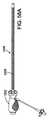
別の代表的な実施形態においては、人工心臓弁を送達するための送達装置は、弁に接続されるように適合される、近位端および遠位端を有する第1の細長いシャフトと、第1のシャフトの上を延在し、弁が半径方向に圧縮された状態の時に、弁の上を延在するように構成されるシースを有する、近位端および遠位端部分を有する、第2の細長いシャフトとを備える。ハンドルは、第1および第2のシャフトの近位端に結合され、ハンドルは、回転可能なアクチュエータ、およびアクチュエータに動作可能に接続され、第2のシャフトの近位端に接続されるネジを備え、アクチュエータの回転は、弁に対して第2のシャフトを後退させるように、第1のシャフトに対する、ネジおよび第2のシャフトの縦方向移動を引き起こす。 In another exemplary embodiment, a delivery device for delivering a prosthetic heart valve includes a first elongate shaft having a proximal end and a distal end adapted to be connected to the valve; A first end having a proximal end and a distal end portion extending over one shaft and having a sheath configured to extend over the valve when the valve is radially compressed; Two elongated shafts. The handle is coupled to the proximal ends of the first and second shafts, the handle includes a rotatable actuator and a screw operably connected to the actuator and connected to the proximal end of the second shaft. The rotation of the actuator causes a longitudinal movement of the screw and the second shaft relative to the first shaft so as to retract the second shaft relative to the valve.
別の代表的な実施形態においては、ステントを有する人工心臓弁を送達するための送達装置は、遠位端部分を有する少なくとも1つの細長いカテーテルと、弁とカテーテルの遠位端部分との間に解放可能な接続を形成するように適合される、解放可能な弁保持機構とを備える。弁保持機構は、カテーテルの遠位端部分から延在する、複数の縫合糸を備え、縫合糸は、ステントの一部分を通って延在してそれに係合し、かつ一端においてループを有する。弁保持機構は、弁をカテーテルに接続するように、各縫合糸のループを通って延在する細長い摺動可能な部材をさらに備える。摺動可能な部材は、摺動可能部材からループを解放するように縫合糸に対して後退可能であり、したがって、弁とカテーテルとの間の接続を解放する。 In another exemplary embodiment, a delivery device for delivering a prosthetic heart valve having a stent includes at least one elongate catheter having a distal end portion and between the valve and the distal end portion of the catheter. And a releasable valve retention mechanism adapted to form a releasable connection. The valve retention mechanism includes a plurality of sutures extending from the distal end portion of the catheter, the sutures extending through and engaging a portion of the stent and having a loop at one end. The valve retention mechanism further comprises an elongated slidable member extending through each suture loop to connect the valve to the catheter. The slidable member is retractable relative to the suture to release the loop from the slidable member, thus releasing the connection between the valve and the catheter.
別の代表的な実施形態においては、人工心臓弁を送達するための送達装置は、人工弁に結合されるように適合される、遠位端部分を有する細長いカテーテルと、弁シースとを備える。弁シースは、カテーテルの遠位端部分に結合された時に、半径方向に圧縮された状態の弁の上を延在するように構成され、弁の上を延在する第1の管状襞層、および第1の襞層の上を延在する第2の管状襞層から形成される、襞状部分を備える。第2の襞層は、弁をシースから抜くために、カテーテルおよび弁に対して縦方向に移動可能である。 In another exemplary embodiment, a delivery device for delivering a prosthetic heart valve comprises an elongated catheter having a distal end portion adapted to be coupled to the prosthetic valve and a valve sheath. A valve sheath configured to extend over the radially compressed valve when coupled to the distal end portion of the catheter, and a first tubular scissor layer extending over the valve; And a ridge portion formed from a second tubular ridge layer extending over the first ridge layer. The second heel layer is movable longitudinally with respect to the catheter and valve to withdraw the valve from the sheath.
別の代表的な実施形態においては、アセンブリは、自己拡張式ステントを備える人工弁であって、ステントは、複数の角度離間した柱を有する、人工弁と、患者の体内の埋込部位に弁を送達するための送達装置とを備える。送達装置は、遠位端部分を有する細長いシャフトを備え、遠位端部分は、その外表面内に形成され、ステントの各柱を受容するように寸法決定される、複数の凹部を有する。送達装置はまた、弁の上を延在し、各凹部内に配置された柱を用いて、弁を圧縮状態で保持するように寸法決定される、外側シースを備え、シースおよびシャフトは、弁をシースから抜くために、互に対して縦方向に移動可能であり、したがって、それが拡張することを可能にする。 In another exemplary embodiment, the assembly is a prosthetic valve comprising a self-expanding stent, the stent having a plurality of angularly spaced columns and a valve at an implantation site in the patient's body. And a delivery device. The delivery device includes an elongate shaft having a distal end portion, the distal end portion having a plurality of recesses formed in an outer surface thereof and dimensioned to receive each column of the stent. The delivery device also includes an outer sheath that extends over the valve and is dimensioned to hold the valve in a compressed state using a post disposed within each recess, the sheath and the shaft including the valve Can be moved longitudinally relative to each other to remove them from the sheath, thus allowing it to expand.
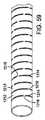
別の代表的実施形態においては、導入器シースは、管腔を有し、患者の血管系に挿入されるように適合される細長い管状スリーブを備える。スリーブは、金属層であって、この金属層の長さに沿って離間した複数のバンドを備える、金属層と、隣接バンド間に挿入された円周方向に延在する開口部とを備える。導入器シースはさらに、スリーブの近位端に結合される、シール筐体を備えることができる。 In another exemplary embodiment, the introducer sheath includes an elongated tubular sleeve having a lumen and adapted to be inserted into a patient's vasculature. The sleeve is a metal layer, comprising a metal layer comprising a plurality of bands spaced along the length of the metal layer, and a circumferentially extending opening inserted between adjacent bands. The introducer sheath can further comprise a seal housing coupled to the proximal end of the sleeve.
さらに別の代表的実施形態においては、導入器シースは、筺体であって、内部孔、筐体上を縦方向に移動可能なキャップ部分、およびキャップ部分上に載置され、内部孔と整列した開口部を有するエラストマーシールを有する筐体を備える。キャップ部分は、シールを半径方向に伸展させて、シールの開口部を拡大するために、筐体上の第1の位置から第2の位置まで移動可能である。導入器シースはまた、筐体の内部孔から延在する、細長い管状スリーブを備えることができ、スリーブは、管腔を有し、患者の血管系の中に挿入されるように適合される。 In yet another exemplary embodiment, the introducer sheath is a housing having an internal bore, a cap portion movable longitudinally over the housing, and mounted on and aligned with the internal bore. A housing having an elastomer seal having an opening is provided. The cap portion is movable from a first position to a second position on the housing to extend the seal radially and enlarge the opening of the seal. The introducer sheath can also include an elongate tubular sleeve extending from the interior bore of the housing, the sleeve having a lumen and adapted to be inserted into the patient's vasculature.
本発明の前述ならびに他の特性および利点は、付随する図面を参照して進める、以下の発明を実施するための形態からより明らかになるであろう。 The foregoing and other features and advantages of the invention will become more apparent from the following detailed description, which proceeds with reference to the accompanying figures.
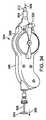
まず、図1を参照すると、一実施形態に従う人工大動脈心臓弁10を示している。弁10は、可撓性弁尖区画14を支持する拡張可能な枠部材またはステント12を含む。弁10は、配備部位までの体内を通しての送達のための圧縮状態まで半径方向に圧縮可能であり、配備部位において、図1に示すその機能的寸法まで拡張可能である。特定の実施形態においては、弁10は、自己拡張式であり、すなわち、弁は、送達シースの遠位端から前進させられたときに、その機能的寸法まで半径方向に拡張することができる。自己拡張式弁の経皮送達および埋込に特に適した装置を、下記に詳細に説明する。他の実施形態においては、弁は、圧縮状態で送達カテーテルのバルーン上に載置されるように適合することができる、バルーン拡張可能な弁であってもよい。弁は、当該技術分野において公知のように、バルーンを膨張させることによって、配備部位において、その機能的寸法まで拡張することができる。 Referring first to FIG. 1, a prosthetic
図示した弁10は、心臓の他の天然弁を置換するために使用することもできるが、天然の大動脈弁輪内に配備するように適合される。また、弁10は、静脈弁等の体内の他の弁を置換するように適合することができる。 The illustrated
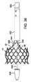
図3および4は、図示目的のために、弁尖区画14のないステント12を示す。示すように、ステント12は、複数の縦方向に延在する、一般的に正弦波形状の枠部材、または支柱16から形成することができる。支柱16は、交番する曲げによって形成され、かつメッシュ構造を形成するように隣接湾曲部の頂点から形成された節部18において溶接されるか、またはさもなければ、相互に固定される。支柱16は、弁が送達装置(下記に説明するもの等)のために、減少された直径まで圧縮されることを可能にし、次いで、送達装置から配備した時に、弁を患者の体内でその機能的寸法まで拡張させる、ニチノールとして公知のニッケルチタン合金等の好適な形状記憶材料から作製することができる。弁が送達装置の膨張可能なバルーン上に圧着され、バルーンの膨張によって、その機能的寸法まで拡張するように適合される、バルーン拡張可能な弁である場合には、ステント12は、ステンレス網等の好適な延性材料から作製することができる。 3 and 4 show a
ステント12は、流入端部26および流出端部27を有する。支柱16によって形成された、メッシュ構造は、一般に、円筒の「上部」部分または流出端部分20と、外向きに弓形に湾曲、または膨満した中間区画22と、内向きに弓形に湾曲した「下部」部分または流入端部分24とを備える。中間区画22は、望ましくは、埋め込まれると、弁を適所に固定することを補助するために、大動脈の基部内のバルサルバ洞内に延在するように寸法決定および成形される。示すように、メッシュ構造は、望ましくは、流入端部26において終端する張り出し部分を形成するように、流出端部分20から中間区画22に向かって徐々に直径が増大し、次いで、中間区画22から流入端部分24上の位置まで徐々に直径が減少し、次いで、徐々に直径が増大する、その全長に沿って湾曲形状を有する。 The
弁が拡張状態にある時に、中間区画22は、直径D1を有し、流入端部分24は、最小直径D2を有し、流入端部26は、直径D3を有し、流出端部分20は、直径D4を有し、そこでは、D2は、D1およびD3未満であり、D4は、D2未満である。また、D1およびD3は、望ましくは、弁が埋め込まれる天然弁輪の直径を上回る。この方法で、ステント12の全体の形状は、埋込部位において弁を保持することを補助する。より具体的には、図5Aおよび5Bを参照すると、弁10は、下部区画24が大動脈弁輪28内に位置し、中間区画24がバルサルバ洞56内まで大動脈弁輪の上を延在し、下部の張り出し端部26が大動脈弁輪の下に延在するように、天然弁(図示した実施例において大動脈弁)内に埋め込むことができる。弁10は、大動脈弁輪28の周辺組織ならびにステントの形状に対する、下部区画24の半径方向外向きの力によって、天然弁内に保持される。具体的には、中間区画24および張り出し下端部26は、上流および下流(大動脈に向かう、およびそこから離れる)方向の弁の軸の脱落に対して、さらに抵抗するために、大動脈弁輪28を超えて半径方向外向きに延在する。図5Bに図示するように、天然弁尖58の状態によって、弁は、典型的には、ステント12の外表面とバルサルバ洞の壁との間で上方に褶曲され、その間で圧縮される、天然弁尖58を有する、天然弁輪28内で配備する。いくつかの場合においては、弁10を埋め込む前に、弁尖58を切除することが望ましい場合があり得る。When the valve is in the expanded state, the
自己拡張式枠を有する公知の人工弁は、典型的には、血管系の非罹患領域内に延在しそこに固定される、さらなる固定デバイスまたは枠部分を有する。ステント12の形状が弁を保持することを補助するので、さらなる固定デバイスは不要であり、ステントの全長Lは、ステントの上部部分20が大動脈の非罹患領域内に延在することを防止するか、または上部部分20が大動脈の非離間領域内に延在する範囲を少なくとも最小化するために、最小化することができる。患者の血管系の非罹患領域を回避することは、今後の介入が必要な場合の副作用を回避することに役立つ。例えば、人工弁は、主に、ステントが弁の罹患部分に固定されるため、患者からより容易に除去することができる。 Known prosthetic valves having a self-expanding frame typically have an additional fixation device or frame portion that extends into and is fixed in an unaffected region of the vasculature. Since the shape of the
特定の実施形態においては、22mm〜24mmの弁輪における使用を目的とした弁では、直径D1は、約28mm〜約32mm、具体的な例としては、30mmであり、直径D2は、約24mm〜約28mm、具体的な例としては、26mmであり、直径D3は、約28mm〜約32mm、具体的な例としては、30mmであり、直径D4は、約24mm〜約28mm、具体的な例としては、26mmである。特定の実施形態において、長さLは、約20mm〜約24mm、具体的な例としては、22mmである。 In certain embodiments, for valves intended for use in an annulus of 22 mm to 24 mm, the diameter D1 is about 28 mm to about 32 mm, a specific example being 30 mm, and the diameter D2 is about 24 mm to About 28 mm, specifically 26 mm, diameter D3 is about 28 mm to about 32 mm, specifically 30 mm, and diameter D4 is about 24 mm to about 28 mm, as a specific example Is 26 mm. In certain embodiments, the length L is about 20 mm to about 24 mm, and a specific example is 22 mm.
図1を参照すると、ステント12は、ステントの上部部分20から延在する柱30(図示した実施形態において3つ)の形態の、複数の角度離間した保持アーム、または突出部を有することができる。各保持アーム30は、弁と送達装置(下記に説明)との間の解放可能な接続を形成するために使用することができる、弁保持機構の突起部を受容するように寸法決定される、各口径部32を有する。さらなる実施形態においては、保持アーム30は、弁保持機構が使用されない場合には、提供する必要がない。 Referring to FIG. 1, the
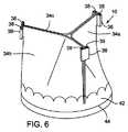
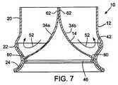
図6および7において最もよく示すように、図示した実施形態において、弁尖アセンブリ14は、可撓性材料から作製される3つの弁尖34a、34b、34cを備える。各弁尖は、流入端部分60および流出端部分62を有する。弁尖は、任意の好適な生物学的材料(例えば、ウシまたはウマの心膜等の心膜組織)、生体適合性剛性材料、または参照により本明細書に組み込まれる、米国特許第6,730,118号に説明されるもの等の他のそのような材料を含むことができる。弁尖アセンブリ14は、弁の流入端部に隣接する縫合糸線44において、弁尖34a、34b、34cの流入端部分の外表面に固定される、環状補強スカート42を含むことができる。弁尖アセンブリ14の流入端部分は、スカート42をステントの下部部分24の支柱16に縫合することによって、ステント12に固定することができる(図1に最もよく示す)。図7に示すように、弁尖アセンブリ14はさらに、弁尖の流入端部分60の内部表面に固定される、内側補強ストリップ46を含むことができる。 As best shown in FIGS. 6 and 7, in the illustrated embodiment, the
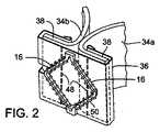
図1および2を参照すると、弁尖アセンブリ14の流出端部分は、弁尖34a、34b、34cの3つの角度離間した交連付着において、ステント12の上部部分に固定することができる。図2に最もよく示すように、各交連付着は、2つの弁尖の交連において、補強区画36を隣接する上部縁部分38に巻きつけ、かつ縫合糸48を用いて、補強区画36を縁部分38に固定することによって、形成することができる。次いで、補強材料および弁尖の挟持された層は、ステントの流出端部に隣接する縫合糸50を用いて、ステント12の支柱16に固定することができる。したがって、弁尖は、望ましくは、流入端部26から流出端部27まで、ステントの全長または実質的に全長に延在する。補強区画36は、縫合糸線における応力集中を最小化し、使用中に屈曲する弁尖の部分上の「針穴」を回避するように、ステントへの弁尖の付着を補強する。補強区画36、スカート42、および内側補強ストリップ46は、望ましくは、ポリテトラフルオロエチレン(PTFE)等の生体適合性剛性材料、またはポリエステル織物(例えば、ポリエチレンテレフタレート(PET))等の織布材料から作製される。 With reference to FIGS. 1 and 2, the outflow end portion of the
図7は、弁10の動作を示す。心拡大期に、弁尖34a、34b、34cは、弁を効果的に閉鎖するように崩壊する。示すように、ステント12の中間区画22の湾曲形状は、中間区画と、バルサルバ洞を模倣する弁尖との間の間隙を画定する。したがって、矢印52で示すように、弁尖が閉鎖する時に、「洞」に進入する逆流は、弁尖の上部表面に沿って血液の乱流を生成する。この乱流は、血栓形成を最小化するために、弁尖およびスカート42を洗浄することを補助する。 FIG. 7 shows the operation of the
参照により本明細書に組み込まれる、米国特許第2008/0065011号にさらに説明されるように、弁10は、送達装置の遠位端において捲縮状態で載置される弁が、大腿動脈を通して体内に導入され、大動脈弓を通して心臓まで前進させられる、逆行性アプローチで埋め込むことができる。 As further described in US 2008/0065011, incorporated herein by reference, the
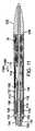
図8は、一実施形態に従う、患者の血管系を通して、上述の弁10等の自己拡張式弁を送達するために使用することができる、送達装置100を示す。送達装置100は、細長いシャフト104を有する、第1の最外部または主要カテーテル102を備え、その遠位端は、送達シース106(送達シリンダとも称される)に結合する。主要カテーテル102の近位端は、送達装置(図示せず)のハンドルに接続される。弁の送達中、外科医は、ハンドルを使用して、患者の血管系を通して送達装置を前進および後退させることができる。必要ではないが、米国特許出願公開第2008/0065011号に開示するもの等の主要カテーテル102は、患者の血管系を通して前進させられる時に、外科医がシャフト104の遠位部分の湾曲または屈曲の量を誘導または制御することを可能にするように構成される、ガイドカテーテルを含むことができる。 FIG. 8 illustrates a
送達装置100はまた、細長いシャフト110(本明細書において、トルクシャフトとも称される)と、シャフト110の上に配置される円筒状ネジ112と、シャフト110の遠位端部分116に接続される弁保持機構114とを有する、第2のカテーテル108(本明細書において、弁カテーテルとも称される)を含む。弁カテーテル108のシャフト110は、送達シース106および主要カテーテル102のシャフト104を通って延在する。送達装置100はまた、細長いシャフト120と、シャフト120の遠位端部分に固定されるノーズ部品122を有する、第3のノーズカテーテル118を含むことができる。ノーズ部品122は、患者の血管系を通す侵襲性追跡に示すように、先細りの外表面を有することができる。ノーズカテーテルのシャフト120は、弁10、保持機構114、および弁カテーテル108のシャフト110を通って延在する。弁カテーテル108のトルクシャフト110は、主要カテーテルのシャフト104およびノーズカテーテルのシャフト120に対して、軸方向に移動可能かつ回転可能になるように構成することができる。送達装置100はまた、下記にさらに説明するように、圧縮状態の弁10を送達シース106の内部に充填するために使用することができる、充填コーン124と共に提供することができる。 The
弁カテーテルシャフト110の遠位端部分116は、ネジ112が載置される端部品156を含むことができる。端部品156は、ネジ112の同様に成形された内表面と嵌合する端部品の長さに沿って、少なくとも部分的に延在する非円形の断面形状を有する(図11に最もよく示す)。例えば、図示した実施形態においては、端部品156の一部分は、ネジ112の正方形に成形された内表面と嵌合する正方形の断面形状を有する。この方法で、シャフト110の回転は、ネジ112の対応する回転を引き起こす。 The
弁カテーテル108は、望ましくは、送達シースからの弁10の増分および制御された前進が生じるように、送達シース106に対して回転可能になるように構成される。したがって、一実施形態に従い、送達シース106(図9〜12に最もよく見られるように)は、第1および第2の細長いカムスロット126、およびネジ112の雄ネジ132に係合するように適合される雌ネジ128を備えることができる。主要カテーテルシャフト104の遠位端部分は、送達シース106内に延在し、かつ送達シースのカムスロット126内に半径方向外向きに延在する、第1および第2の突起部130で形成することができる。 The
図11に最もよく示すように、シャフト110の遠位端部分は、端部品156の近位端部分の上に延在し、接着剤等を用いてそこに固定される。ネジ112は、送達シース106内の端部品56上に配置される。ネジ112の遠位端および端部品56は、弁カテーテルシャフト110の回転が、端部品56、ネジ112、および弁10の対応する回転を引き起こすために効果的であるように、保持部材114を介して弁10に結合される。シース106に対するシャフト110およびネジ112の回転は、シャフト110および弁10を、シース106に対して、近位または遠位方向(それぞれを矢印134aおよび134bで示す)のいずれかに、縦方向に移動させるために効果的である。下記にさらに説明するように、弁配備中の近位方向のシャフト110の移動は、シースの開口遠位端136から弁10を前進させる。 As best shown in FIG. 11, the distal end portion of
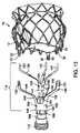
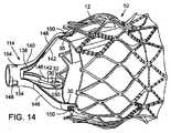
図13および14に最もよく示すように、弁保持機構114は、内側フォーク138、および外側フォーク140を含む。内側フォーク138は、ステント12の保持アーム30に対応する、複数(図示した実施形態において3つ)の角度離間した突起部142を含み、その突起部は、内側フォークの近位端において、ヘッド部分144から延在する。外側フォーク140は、同様に、ステント12の保持アーム30に対応する、複数(図示した実施形態において3つ)の角度離間した突起部146を含み、その突起部は、外側フォークの近位端においてヘッド部分148から延在する。 As best shown in FIGS. 13 and 14, the
外側フォークの各突起部は、内側フォークの対応する突起部と協働して、ステントの保持アーム30との解放可能な接続を形成する。図示した実施形態においては、例えば、各突起部146の遠位端部分は、開口部150で形成される。組み立てられた時(図15に最もよく示すように)、保持アーム30が開口部150から後退して出ないように、ステントの各保持アーム30は、外側フォークの突起部146の開口部150を通して挿入され、内側フォークの突起部142は、保持アーム30の開口部32を通して挿入される。見てとれるように、開口部32から突起部を除去するために、突起部142を近位に(矢印152の方向に)後退させることは、弁10を保持機構から解放するために効果的である。この方法で、保持機構114は、送達シースから配備した後に、ユーザが弁の位置を微調整または調節することを可能にするために、弁カテーテル108に対して弁を保持することが十分に確保されている弁との解放可能な接続を形成する。下記にさらに説明するように、弁が所望の埋込部位に位置する時に、弁と保持機構との間の接続は、外側フォーク140に対して内側フォーク138を後退させることによって、解放することができる。 Each protrusion on the outer fork cooperates with a corresponding protrusion on the inner fork to form a releasable connection with the
内側フォークのヘッド部分144は、弁カテーテルシャフト110に接続することができる一方、ヘッド部分148は、ネジ112に接続することができる。図13に示すように、例えば、内側フォークのヘッド部分144は、複数の角度離間した、内向きに偏向された保持フランジ154で形成することができる。弁カテーテルシャフト110の端部品156は、円柱溝部160を有する円筒シャフト158で形成することができる。シャフト158は、フランジ154の内部遊離端によって画定された直径をわずかに上回る外径を有する。したがって、内側フォーク138は、フランジ154が溝160内に内向きに湾曲するまで、シャフト158をヘッド部分144内に挿入することによって、端部品156に固定することができ、それによって、ヘッド部分144とシャフト158との間の嵌合接続が形成される。図16で見てとれるように、ヘッド部分144がシャフト158上に挿入される時に、端部品156が、内側フォークに対して近位または遠位方向に縦方向に移動することを防止するように、溝160内の管状肩部162は、フランジ154の遊離端の反対に位置し、端部品156の別の管状肩部164は、ヘッド部分144の近位端の反対に位置する。 The inner
外側フォークのヘッド部分148は、同様の方法で、ネジ112の遠位端に固定することができる。図16に最もよく見られるように、ヘッド部分148は、複数の角度離間した、内向きに偏向された保持フランジ155で形成することができる。ネジ112の遠位端部分は、環状溝168を有する円筒シャフト166で形成することができる。シャフト166は、フランジ155の遊離端によって画定される直径をわずかに上回る外径を有する。したがって、外側フォーク140は、フランジが内向きに溝168内に湾曲するまで、シャフト166をヘッド部分148に挿入することによって、ネジ112に固定することができ、それによって、ヘッド部分148とシャフト166との間の嵌合接続が形成される。図16に見てとれるように、ヘッド部分148がシャフト166上に挿入される時に、ネジが、外側フォークに対して、近位または遠位方向に縦方向に移動することを防止するように、溝168内の管状肩部170は、フランジ156の遊離端の反対に位置し、ネジ112の別の管状肩部172は、ヘッド部分の近位端の反対に位置する。 The outer
弁10は、以下の方法で、充填コーン124を使用して、圧縮され、送達シース106内に充填することができる。第1に、図17に示すように、弁10は、上述のように、保持機構114に固定することができる。充填コーン124は、一方の端部において第1の開口部176と、他方の端部において第2のより小さい開口部178と、第1の開口部における第1の直径から、第2の開口部178に近接する、第2のより小さい直径まで先細りになる、先細りの内部表面180とを含む。図18に示すように、保持部材114が充填コーンの外に延在するまで、保持機構114および弁10は、充填コーン124を介して、矢印174の方向に押し出し、保持部材および弁を半径方向に圧縮することができる。弁の圧縮を促進するために、弁および保持機構を冷水槽内に浸漬しながら、後者ステップを実施することができる。 The
図19および20を参照すると、弁は、充填コーン124によって、その圧縮状態に保持される一方、端部品156は、上述のように、シャフト158を内側フォークのヘッド部分144内に矢印182の方向に挿入することによって、内側フォークに固定される。図21および22を参照すると、次いで、ネジ112は、上述のように、シャフト166を外側フォークのヘッド部分148内に挿入することによって、端部品156の上を矢印184の方向に摺動し、かつ外側フォーク140に固定することができる。続いて、図23および24を参照すると、送達シース106は、ネジの近位端をシース106の遠位端に接触させ、次いで、弁カテーテルシャフト110を回転することによって、ネジ112の上に定置され、それは、シースをネジの上で前進させる。シャフト110の連続した回転により、シース106を保持部材114および弁10の上を前進させ、次いで、シースが充填コーンから出るときに、それが弁の上を前進することを可能にするように充填コーンを押し離す。図9および11に図示するように、弁が完全にシースの内側になるまで、シャフト110を回転する。 Referring to FIGS. 19 and 20, the valve is held in its compressed state by the filling
ノーズコーン122が使用される時、ノーズコーンが弁10に沿って充填コーンを介して摺動することができるように、ノーズコーンは、望ましくは、充填コーンの開口部178より小さい外径を有する。さらなる実施形態においては、従来の圧着機構を使用して、弁10を半径方向に圧縮することができる。 The nose cone desirably has an outer diameter that is smaller than the
弁10が送達シース106内に充填されると、送達装置100は、患者の体内に挿入することができる。1つのアプローチにおいては、弁は、送達装置が大腿動脈内に挿入され、患者の血管系を通して心臓まで前進させられる、逆行性アプローチで送達することができる。送達装置の挿入前に、導入器シースは、患者の血管系を通って、大動脈を通して左室内に前進させられる、ガイドワイヤの後に、大腿動脈内に挿入することができる。次いで、送達装置100は、導入器シースを介して挿入され、弁10を含む送達装置の遠位端部分が、天然大動脈弁に隣接する位置か、またはその中の位置まで前進させられるまで、ガイドワイヤの上を前進させることができる。 Once the
その後、弁10は、ガイドカテーテル102に対して弁カテーテル108を回転することによって、送達装置100から配備することができる。上記のように、弁カテーテルは、外科医が主要カテーテル102に対する弁カテーテル108の回転を引き起こすことを可能にする、弁カテーテルシャフト110の近位端に接続される、回転可能なハンドル部分(図示せず)を有することができる。弁カテーテル108の回転は、主要カテーテルシャフト104およびシースに対する、弁カテーテルシャフト110、端部品156、およびネジ112の対応する回転を引き起こし、それは、次に、弁10をシースの開口端部から前進させるために、これらの構成要素を送達シース106に対して遠位に前進させられる。弁カテーテル108の回転は、弁が送達シースの開口遠位端から前進し、拡張し始めると、正確で制御された方法で弁をシースに対して移動させる。したがって、公知の送達装置とは異なり、送達装置から弁が前進し、拡張し始めると、弁は、シースの遠位端に対する弁の拡張力によってもたらされた、シースからの非制御された移動に対して維持される。また、弁がシースから部分的に前進させられた後に、それは、例えば、弁を再設置するか、または弁を体内から完全に引き出すために、弁をシース内に再度後退させることが望ましい場合があり得る。部分的に配備した弁は、カテーテルシャフト110が後退され、弁をシース内に引き戻す、弁カテーテルの回転を逆転することによって、シース内に再度後退させることができる。 The
公知の送達デバイスにおいては、外科医は、弁をシースから抜くために、押し引き力をシャフトおよび/またはシースに印加しなければならない。したがって、シャフトを歪曲する(例えば、シャフトを軸方向に圧縮または伸展する)ことなく、デバイスの遠位端に力を伝達することは困難であり、それは、次に、シースから抜くプロセス中の弁の非制御された動作を引き起こす。この影響を軽減するために、シャフトおよび/またはシースは、より剛性に作製することができ、それは、デバイスが血管系を通して操縦することがより困難になるので望ましくない。対照的に、上述の弁をシースから抜く方法は、公知のデバイスに必要とされる、シャフト上への押し引き力の印加を排除し、それによって、デバイスの可撓性を低下させることなく、比較的高い正確な力をシャフトの遠位端に印加することができる。特定の実施形態においては、シースから抜くプロセスに悪影響を及ぼすことなく、20lbsだけ高い力をトルクシャフトの端部に伝達することができる。対照的に、押し引き機構を使用する従来のデバイスは、典型的には、シースから抜くプロセス中に、約5lbsの力を超えることができない。 In known delivery devices, the surgeon must apply a push / pull force to the shaft and / or sheath in order to withdraw the valve from the sheath. Thus, it is difficult to transmit force to the distal end of the device without distorting the shaft (eg, compressing or extending the shaft axially), which in turn is a valve in the process of being pulled out of the sheath Cause uncontrolled behavior. To mitigate this effect, the shaft and / or sheath can be made more rigid, which is undesirable because it makes the device more difficult to navigate through the vasculature. In contrast, the above-described method of withdrawing the valve from the sheath eliminates the application of pushing and pulling forces on the shaft required for known devices, thereby reducing the flexibility of the device, A relatively high and precise force can be applied to the distal end of the shaft. In certain embodiments, a force as high as 20 lbs can be transmitted to the end of the torque shaft without adversely affecting the process of withdrawal from the sheath. In contrast, conventional devices that use a push-pull mechanism typically cannot exceed a force of about 5 lbs during the process of pulling out of the sheath.
弁10が送達シースから前進させられ、その機能的寸法まで拡張した後において(図10に示すように)、弁は、保持機構114を介して送達装置に接続されたままである。したがって、弁が送達シースから前進させられた後に、外科医は、弁の対応する動作を引き起こす、送達装置を近位および遠位方向または左右に移動させるか、または伝達装置を回転させること等によって、天然弁内の所望の埋込位置に対して弁を再設置することができる。保持機構114は、望ましくは、弁の位置が、天然弁内の所望の埋込位置に対して調節されると、血流に対して、送達装置に対する弁の位置を保持することを十分に確保し、かつ剛性である、弁と送達装置との間の接続を提供する。外科医が弁を天然弁内の所望の埋込位置に設置すると、弁と送達装置との間の接続は、弁カテーテルシャフト110をガイドカテーテルに対して近位方向に後退させることによって、解放することができ、それは、その突起部142を弁の保持アーム30内の開口部32から引き出すように、内側フォーク138を後退させるために効果的である(図26および27)。送達装置の後退は、保持機構114から弁を完全に切断するように、外側フォーク140を後退させる(図28)。その後、送達装置は、弁を天然弁内に埋め込んだまま(図5Aおよび5Bに示す等)、体内から引き出すことができる。 After the
さらなる実施形態においては、送達装置は、バルーン拡張可能な人工弁を送達するように適合することができる。上述のように、保持機構114を使用して、弁を送達装置の端部に固定することができる。弁のステントが自己拡張式ではないため、シース106は、任意である可能性がある。保持機構114は、導入器シースを介する送達装置および弁アセンブリの押し能力を強化する。 In a further embodiment, the delivery device can be adapted to deliver a balloon expandable prosthetic valve. As described above, the
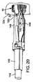
図29Aは、別の実施形態に従う、送達装置の遠位端部分200を示す。送達装置200は、送達装置100と同様の構成を有し、多くのそれと同一の構成要素(いくつかの共通する構成要素は、明確にするために図29Aから除去される)を有する。送達装置200は、細長い弁カテーテル202を備える。弁カテーテル202は、細長い可撓性トルクシャフト204と、シャフト204の遠位端に固定される端部品206と、トルクシャフト204から延在する外側シャフト220とを備える。 FIG. 29A shows a
送達シース208は、外側シャフト220の遠位端に固定される。送達シース208は、シャフト204の遠位端部分、端部品206、弁保持機構114、およびシースの内側に圧縮状態で保持される弁10の上に配置される。保持機構114の外側フォーク140のみを図29Aに示す。外側フォーク140のヘッド部分148は、上述のもの等の端部品の階段状シャフト部分210との嵌合接続を形成すること等によって、端部品206に固定することができる。内部フォーク138(図29Aに図示せず)は、そのヘッド部分144において、弁カテーテルシャフトを通って延在する、内側シャフトの遠位端(図29Aに図示せず)に接続することができる。内部シャフトは、細長いノーズカテーテル118のシャフト120であってもよい(図8)。内部フォーク138の突起部142は、上記に説明するように、弁10を送達装置に固定するために、ステント12内の開口部32を通って延在する。内部フォーク138が、シャフト204を通って延在する内部シャフトに固定されるため、内部フォーク138は、シャフト204に対して、内部シャフトを近位方向に後退させることによって、内部フォークの突起部を外側フォーク140に対して後退させて、ステントの開口部から引き出すことができる(それによって、弁10を解放する)。
図示した構成のシャフト204は、可撓性の溝付き管を含む、第1の層212と、第1の層212の周辺にらせん状に巻かれるワイヤコイルを含む、第2の層214とを含む。第1の層212は、金属(例えば、ステンレス網)、ポリマー材料、または別の好適な材料から作製することができる。ワイヤコイル214は、他の材料を使用することができるが、例えば、ステンレス網ワイヤであってもよい。ワイヤコイル214は、少なくともシャフト204の遠位端部分に沿って延在し、シース208の雌ネジ216に係合する。この方法で、ワイヤコイル214は、シャフト204の雄ネジとしての機能を果たす。トルクシャフト204を外側シャフト220に対して回転する時に、シース208は、シャフト204の回転が、弁10を配備するために、シャフト204をシース208に対して遠位に前進させるように、外側シャフト220によるシャフト204との回転に対して保持される。 The
使用中、送達装置200は、患者の血管系に挿入され、心臓の埋込部位まで前進させられる。次いで、トルクシャフト204は、弁10がシースから抜かれて、その機能的寸法まで拡張するまで、外側シャフト220に対して回転し、シャフトを遠位方向に(矢印218で示すように)前進させる。この地点において、弁10は、保持機構114によって送達装置に接続されたままであり、それによって、ユーザは、埋込部位において、拡張した弁の位置を微調整することができる。弁が所望の配向になると、保持機構114によって形成された接続は、上述のように内側シャフトを後退させることによって、解放することができる。その後、保持機構は、シース内に再度後退させることができ、送達装置のすべてを体内から除去することができる。 In use, the
図29Bは、別の実施形態に従う、送達装置の遠位端部分250を示す。送達装置250は、送達装置100と同様の構造を有し、かつ多くのそれと同一の構成要素(いくつかの共通する構成要素は、明確にするために、図29Bから除去される)を有する。送達装置250は、送達シース256内に延在する細長い可撓性トルクシャフト254を備える、細長い弁カテーテル252を備える。シャフト254は、例えば、示すようなコイル状シャフト、またはケーブル(例えば、ステンレス網ケーブル)を備えることができる。第1のネジ部材258は、シースのシャフト254の遠位端部分上に配置されそこに固定され、第2のネジ部材260は、シースの第1のネジ部材上に配置される。第1のネジ部材258は、第2のネジ部材260の雌ネジに係合する雄ネジを有する。第2のネジ部材260はまた、シース256の雌ネジに係合する雄ネジを有する。 FIG. 29B shows the
送達装置はさらに、シャフト254の上を延在する外側シャフト264を含むことができ、シース256の近位端に固定される遠位端部分を有する。トルクシャフト254は、外側シャフト264およびシース256に対して回転させて、シースから弁を配備させるために、シースに対してトルクシャフトを縦方向に前進させることができる。環部材266は、トルクシャフト254の外表面上に載置され、トルクシャフトの回転時に、外側シャフト264に対して、トルクシャフトと共に縦方向に移動する。環部材266は、下記にさらに説明するように、トルクシャフト254が、所定距離だけ遠位方向に前進させられた後に、第2のネジ部材260に接触し、それをシース256内に前進させるように位置する。 The delivery device can further include an
図29Bにさらに示すように、弁保持機構114の外側フォーク140は、そのヘッド部分148において、第1のネジ部材258の階段状シャフト部分262に固定することができ、それは、次に、トルクシャフト254に固定される。内側フォーク138(図29Bにおいて図示せず)は、そのヘッド部分において、トルクシャフト254を通って延在する、内側シャフト(図示せず)の遠位端に接続することができる。内側フォークの突起部は、上述のように、シャフト254の遠位端から延在し、外側フォークの突起部と協働して、ステントの柱30との解放可能な接続を形成する。トルクシャフト254に対して内側シャフトを後退させることによって、内部フォークは、外側フォークに対して後退させられ、柱30への接続を解放することができる。 As further shown in FIG. 29B, the
使用中、送達装置250は、患者の血管系の中に挿入され、心臓の埋込部位まで前進させられる。弁の配備を開始するために、トルクシャフト254は、外側シャフト264に対して回転させられ、それは、シースの遠位端から弁10を部分的に前進させるために、第2のネジ部材260およびシース258に対して、第1のネジ部材258を回転させ、かつ遠位方向に前進させる。トルクシャフト254が所定距離だけ前進させられた後に、環部材266は、トルクシャフト254の回転が、シースから弁10を完全に前進させるために、第1のネジ部材および第2のネジ部材をシースに対して遠位方向に(矢印268の方向に)前進させることに効果的であるように、第2のネジ部材260と接触する。弁が所望の配向になると、保持機構114によって形成された接続は、上述のように内側シャフトを後退させることによって解放することができる。その後、保持機構は、シース内に再度後退させることができ、送達装置のすべてを体内から除去することができる。 In use, the
図30〜37は、別の実施形態に従う送達装置300を図示する。図30〜33は、送達装置300の遠位端部分を示す。図34〜35は、送達装置300の近位端部分を示す。図36〜37は、送達装置300の弁10の配備を示す(弁の弁尖は、図において、明確にするために除去される)。 30-37 illustrate a
送達装置300は、装置の遠位端における弁保持機構306(図32および33)と、装置の近位端におけるハンドル部分308(図34および35)との間に延在する、細長いシャフト304を有する、第1の外側カテーテル302を備える。主要カテーテルシャフト304の遠位端は、弁保持機構306に結合され、それは、次に弁10に固定される。外側カテーテル302は、患者の血管系を通る送達装置の前進を促進するために、シャフト304の一部分の選択的湾曲または屈曲を可能にするように構成される、ガイドカテーテルであってもよい。
送達装置はまた、主要カテーテルシャフト304を通って延在する、細長いトルクシャフト312を有する、第2のトルクカテーテル310を含む。トルクシャフト304の遠位端は、保持機構306を通って延在する可撓性シャフト316と、シャフト316の長さに沿って離間する1つ以上のネジ部材318とを備える、可撓性ネジ機構314に接続される(図32および33)。図33に示すように、ネジ機構314のシャフト316は、患者の血管系を通る送達装置の追跡を補助するために、湾曲または屈曲を可能にするために十分な可撓性を呈する。主要カテーテルシャフト304は、ネジ部材318の雄ネジに係合する雌ネジで形成することができる。例えば、主要シャフト304の遠位端部分(例えば、シャフト304の遠位端において、11mmのセグメント)は、雌ネジで形成することができる。トルクシャフト312の近位端部分は、下記にさらに説明するように、ハンドル部分308内に延在し、そこで、それは、主要カテーテルシャフト304に対するトルクシャフトの回転を可能にするように、制御ノブ320に結合する(図34および35)。 The delivery device also includes a
動作中、各ネジ部材318は、主要シャフト304の雌ネジ部分を通過しそれに係合する。ネジ部材318は、望ましくは、ネジ部材が雌ネジを通過すると、トルクシャフトへの軸方向に向けられた力の印加を防止するか、またはそれを少なくとも最小化するように、調節ネジ部材318が主要シャフトの雌ネジの他方の端部から係脱する前に、ネジ部材318が主要シャフト304の雌ネジ部分の一方の端部に係合することができるように、相互から離間される。この方法で、比較的高いシースから抜く力を、送達装置の全体の可撓性を損なうことなく、シースに印加することができる。 In operation, each
送達装置はまた、その遠位端においてノーズ部品328に接続される、細長いシャフト326を有する、第3のノーズカテーテル324を含むことができる。ノーズカテーテルシャフト326は、トルクシャフト312を通って延在し、ハンドル部分308の近位端から外向きに延在する近位端部分を有する(図34および35)。主要カテーテルシャフト304、トルクシャフト312、およびノーズカテーテルシャフト326は、望ましくは、相互に対して軸方向に移動可能になるように構成される。 The delivery device can also include a
図30および31に示すように、送達装置はさらに、圧縮された弁10の上を延在する移動可能なシース322を含むことができる。シース322は、トルクシャフト312およびネジ機構314の縦方向移動が、シース322の対応する縦方向移動を引き起こすようにネジ機構314に接続される。例えば、シースは、フィンガ316の各口径部362(図32)内に延在する、内向きに延在する突起部358(図31)を有することができ、それは、次に、可撓性シャフト316の遠位端に接続される。フィンガ362は、望ましくは、シャフト316がそれぞれ遠位または近位方向に移動する時に、シャフト316がフィンガ362に対して回転することを可能にするために、フィンガ362を押すか、または引く猿環接合によって、シャフト316に接続される。その結果、下記にさらに説明するように、主要シャフト304に対するトルクシャフト312およびネジ機構314の回転は、シースからの弁の制御された配備を可能にするように、弁に対して、シースを近位方向および遠位方向(図30において両矢印330で示すように)に移動させることに効果的である。 As shown in FIGS. 30 and 31, the delivery device can further include a
図32および33を参照すると、弁保持機構306は、外側フォーク330と、内側フォーク332とを備える。フィンガ362の一部分は、内側フォーク332を示すために、図33から切り離されている。外側フォーク330は、ヘッド部分334と、ヘッド部分334から延在する、複数(図示した実施形態において3つ)の細長い可撓性突起部336とを備える。ヘッド部分334は、上述のように、外側フォークが階段状主要カテーテルシャフト304のシャフト部分との嵌合接続を形成することを可能にするように、弾性保持フランジ338で形成することができる。内側フォーク332は、ノーズカテーテルシャフト326に固着されるヘッド部分340と、ヘッド部分340から延在する複数の細長い突起部342とを有する。外側フォークの突起部336の遠位端部分は、弁10の各保持アーム30を受容するように寸法決定される、口径部344を使用して形成することができる。内側フォーク332の突起部342の遠位端は、上述および図14〜16に示す弁保持機構114と同様に、保持アーム30の口径部32を通って延在して、弁10を固定するための解放可能な接続を形成する。シース322から弁が配備させられた後に、弁と保持機構306との間の接続は、保持アーム30の口径部32から突起部342を引き出すために、主要カテーテルシャフト304に対してノーズカテーテルシャフト326を後退させることによって、解放することができる。ネジ機構314の外側突起部336およびシャフト316は、送達装置が患者の血管系を通って埋込部位まで前進させられると、送達装置の部分が湾曲または屈曲することを可能にするが、それがシース322から配備させられた後に、弁の再設置を可能にすることに十分な剛性であるような、十分な可撓性を呈する。突起部336を含む外側フォーク330は、所望の可撓性を提供する、金属(例えば、ステンレス網)またはポリマー等の様々な好適な材料のうちのいずれかから作製することができる。 Referring to FIGS. 32 and 33, the
図34および35を参照すると、ハンドル部分308は、第1のギア348および第2のギア350を収容する筐体346を備える。第1のギア348は、筐体を通って延在し、筐体の外部に位置する制御ノブ320に接続されるシャフトを有する。第2のギア350は、トルクシャフト312の上に配置されそこに固着される。したがって、制御ノブ320の手動回転は、第1のギア348の回転を引き起こし、それは、次に、第2のギア350を回転させる。第2のギア350は、主要カテーテルシャフト304、弁保持機構306、および弁10に対して、トルクシャフト312およびネジ機構314を回転させる。トルクシャフト312およびネジ機構314の回転は、次に、弁に対するシース322の直線運動を引き起こす。 With reference to FIGS. 34 and 35, the
使用中、弁10は、半径方向に圧縮された状態でシース322内に充填され(図30に示すように)、それは、例えば、上述の充填コーン124を使用することによって達成することができる。次いで、送達装置300は、患者の血管系の中に挿入され、埋込部位における位置か、またはそれに隣接する位置まで前進させられる。次いで、弁10は、ハンドル部分上のノブ320を回転させることによって、シースから配備することができ、それは、次に、トルクシャフト312およびネジ機構316が主要シャフト304内に後退させられ、それによって、図31に示すように、弁を露出するために、シース322が近位方向(図31において矢印352)に移動させられる。ノブ320の回転は、弁配備中にシース322の制御された正確な後退を可能にする。有利に、シースから抜くプロセス中に、弁の位置が埋込部位において弁輪に対して一定に維持することができる一方で、シースは後退させられている。反対方向のノブの回転は、弁を再度被覆するために、シースを遠位方向に移動させる。したがって、体内の送達装置を再設置するか、または送達装置および弁を体内から完全に引き出す必要がある場合には、シースから弁が少なくとも部分的に前進させられた後に、ノブの回転を逆転させて、弁を圧縮状態のシース内に再度戻すことが可能である。 During use, the
送達シースから弁10が前進させられ、その機能的寸法まで拡張した後に(図36に示すように)、弁は、保持機構306を介して送達装置に接続されたままである。その結果、送達シースから弁が前進させられた後に、外科医は、弁の対応する移動を引き起こすか、送達装置を近位および遠位方向、または左右に移動させるか、または送達装置を回転させること等によって、天然弁の所望の埋込位置まで弁を再設置することができる。保持機構306は、望ましくは、弁の位置が天然弁の所望の埋込位置に対して調節されると、血流に対して、送達装置に対して弁の位置を保持することを十分に確保し、剛性である弁と送達装置との間の接続を提供する。外科医が弁を天然弁の所望の埋込位置に位置付けると、外科医は、主要カテーテルシャフト304に対して、ノーズカテーテルシャフト326の近位端354を近位方向(図34において矢印356で示すように)に引くことによって、弁と送達装置との間の接続を解放することができ、それは、弁の保持アーム30の開口部32からその突起部342を引き出すために、内側フォーク332を後退させることに効果的である(図37)。主要カテーテルシャフト304の後退は、外側フォーク330を後退させて、保持機構306から弁を完全に切断する(図37に示すように)。その後、保持機構は、シース322内に再度後退させることができ、送達装置は、弁を天然弁(図5Aおよび5Bに示すもの等)の中に埋め込んだまま、体内から引き出すことができる。 After the
弁10が保持機構306に依然として接続されているが、シースから完全に配備させられた後に、外科医が手術を中断することを決断する場合には、膨張した弁をシース内に再度後退させることは不可能であり得る。したがって、図38A〜38Cは、拡張した弁10をシース322内に再度回収する上で補助するために、送達装置300と共に使用することができる、弁回収デバイス400の一実施形態を示す。図示した実施形態における弁回収デバイス400は、患者の血管系の中に挿入され、主要カテーテルシャフト304の上を前進するように構成される、細長い、一般に円筒状本体を備える。本体の遠位端部分は、通常、圧縮状態、一般に、円筒形体(図38Aに示すように)で保持される、複数の細長い可撓性フラップ部分402を備え、相互から半径方向外向きに屈曲して、拡張した弁10の近位端を受容することに十分大きい、一般にコーン形状の容器を形成することができる(図38Bおよび38C)。フラップ部分402は、望ましくは、図38Bおよび38Cに示す拡張状態を超えて拡張することから防止される。また、フラップ部分402は、円周方向に互いに重なるように寸法化され、それによって、フラップ部分が拡張する時に、それらは、フラップ部分間に任意の隙間を有さない、連続的外表面を有するコーンを形成する。フラップ部分402の拡張を生じさせるために、各フラップ部分は、回収デバイス400の長さに沿って、その近位端に延在する、各プルワイヤに接続することができる。張力がプルワイヤの近位端に印加される時に、フラップ部分は、相互から半径方向外向きに屈曲する。また、フラップ部分402は、回収プロセス中に、血液がフラップ部分を通って流れることを可能にする、メッシュ材料、または有孔ホイル等の有孔材料から作製することができる。 If the
あるいは、フラップ部分402は、ニチノール等の形状記憶材料から作製することができ、かつ自己拡張型である。自己拡張型フラップ部分は、通常、図38A〜38Bに示す拡張構造を取る。フラップ部分402は、外側シース406によって、半径方向に圧縮された状態に保持することができる(図38A)。シース406が、フラップ部分402に対して矢印408の方向に後退させられる時に、フラップ部分402は、図38A〜38Bに示す拡張構造に拡張する。 Alternatively, the
上述のように、回収デバイス400を使用して、完全に拡張した弁を回収し、それを患者の体内から除去することができる。図38Aに示すように、使用中、回収デバイス400は、カテーテルシャフト304の上を通って体内に挿入され、配備された弁10に向かって前進させられる。図38Bおよび38Cに示すように、次いで、フラップ部分402は、弁を係合するために、拡張され、遠位方向にさらに前進させられる。回収デバイスが弁の上を前進すると、弁は、圧縮させられる。弁がシース322への挿入を可能にすることに十分小さい直径まで圧縮される時に、シース322は、シースが弁の上を延在するまで、(例えば、ノブ320の回転によって)遠位方向に前進させられる。弁がシースの内側にあると、回収デバイスの後に、送達装置および弁は、患者の体内から除去することができる。 As described above, the
特定の実施形態においては、回収デバイス400の細長い本体の一部分は、ネジ部材318のネジ山に係合するように適合される、雌ネジを有することができ(図32)、それによって、回収デバイスは、ノブ320の回転によって遠位および近位方向に移動することができる(図34)。使用中、回収デバイスは、体内に挿入され、回収デバイスのネジ山部分がネジ部材318に係合するまで、主要カテーテルシャフト304の上を前進させられる。次いで、フラップ部分402は、拡張させられ、回収デバイスおよびシースは、ノブ320の回転によって拡張した弁の上を前進させられる。フラップ部分402の遠位端は、シース322の遠位端を越えて延在し、それによって、両方が前進させられると、弁の近位端は、まず、フラップ部分と接触し、シース内への弁の挿入を促進するように圧縮し始める。 In certain embodiments, a portion of the elongate body of the
図39は、送達装置300の修正を図示する。この実施形態においては、弁10は、弁を包囲する、1つ以上の解放可能なバンド370等の回収デバイスによるシース322からの配備後に、その圧縮状態に維持される。バンド370は、バンドが開口し、弁が拡張することを可能にする、スネアデバイスを引くか、または移動させることによって、解放することができる。あるいは、バンド370は、弁が埋込部位に前進させられた後に体内で溶解する、生体吸収性または可溶性材料から作製することができる。弁がシースから前進させられる間に、弁がその圧縮状態に維持されるため、シースの端部からの弁の「跳躍」の問題は、弁のより制御された送達を可能にするように、回避することができる。バンド370または同様の抑制デバイスが使用される場合には、送達装置は、シースを通して弁を押すように操作可能である、従来の押し出しシャフトを用いることができ、シースからの弁の配備を生じるように回転させられる、回転トルクシャフトを含む必要はない。言い換えると、バンド370または同様の抑制デバイスは、オペレータが、シースから弁を押すようにシャフトを押す、従来の送達装置と共に使用することができる。さらに、いくつかの実施形態においては、送達装置は、抑制デバイスが患者の血管系を通って、埋込部位に前進させられると、弁をその圧縮状態に保持することができるという事実により、送達中に圧縮された弁を被覆するシースを含む必要はない。 FIG. 39 illustrates a modification of the
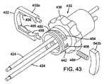
図40は、別の実施形態に従う、送達装置400を図示する。送達装置400は、細長いシャフト404を有する第1の最外部または主要カテーテル402を含み、その遠位端は、弁送達中に圧縮状態の弁10の上を延在し、それを保持するように寸法決定される送達シース406に結合される。シャフト404の近位端は、送達装置のハンドルアセンブリ408に接続される。送達装置はまた、シャフト404から延在する、細長いシャフト412を有する、第2のカテーテル410(弁カテーテルとも称される)を含む。送達装置はまた、細長いシャフト416と、シャフト416の遠位端部分に固定される、ノーズ部品418とを有する、第3のノーズカテーテル414を含むことができる。ノーズカテーテルシャフト416は、弁カテーテルシャフト412を通って延在し、ガイドワイヤを受容するための管腔を含むことができる。シャフト404、412、および416は、望ましくは、遠位および近位方向の相互に対して軸方向に移動可能になるように構成される。 FIG. 40 illustrates a
図46に最もよく示すように、ノーズ部品418は、患者の血管系を通る送達装置の非侵襲的追跡のための先細りの遠位端部分と、シース406内に延在する先細りの近位端部分とを有することができる。弁が配備させられた後に、ノーズ部品の先細りの近位端部分は、体内から送達装置を引き出すために、シース406内にノーズ部品がより容易に再度挿入されることを可能にする。シース406は、ノーズ部品をシース内に再度後退させる操作を補助するための放射線不透過性先端部分490を含むことができる。 As best shown in FIG. 46, the
図48に最もよく示すように、弁カテーテルシャフト412は、X線造影液体等の造影剤を、弁を取り囲む間隙内のシース406内に導入するために、1つ以上の管腔492を有することができる。シース406は、患者の血管系の中に造影剤を注入するための、1つ以上の口径部494(図46および48)を有することができる。ハンドルアセンブリ408は、管腔内に造影剤を導入するために、管腔492と液体連通する、個別の入口部を有することができる。造影剤は、人工弁を移植するための所望の位置を特定することを補助するために、人工弁を配備させる前に、天然弁に隣接する患者の血管系の中に注入することができる。例えば、大動脈弁を置換する時に、造影剤は、天然弁尖の基質にすぐ隣接する大動脈内に注入することができる。これは、人工弁を配備させるための所望位置の特定に役立つように、オペレータに視覚的フィードバックを提供する。人工弁が埋め込まれた後に、さらなる造影剤を、人工弁の弁尖にすぐ隣接する場所に注入して、人工弁の操作の視覚的フィードバックを提供することができる。 As best shown in FIG. 48, the
具体的な実施形態においては、シース406の内径は、約0.265インチ未満であり、シースの外径は、約0.28インチ未満である。 In a specific embodiment, the inner diameter of the
図41を参照すると、図示した構造におけるハンドルアセンブリは、シャフト404、412および416の近位端部分を収容する筐体420と、ネジシャフト422とを含む。ネジシャフト422は、縦方向移動のために、細長い支持ロッド424上の筐体420の内部に載置される。支持ロッド424の遠位端は、遠位ブラケット426によって支持することができ、支持ロッドの近位端は、近位ブラケット428によって支持することができる。主要シャフト404の近位端は、スタブシャフト430に固定することができ、それは、次に、接着する等によって、ネジシャフト422の内部に固定することができる。下記にさらに説明するように、ネジシャフト422は、ノブの回転時に、ネジシャフト422および主要シャフト404の縦方向移動を制御するように動作可能である、アクチュエータまたは制御ノブ432に動作可能に接続される。ハンドルアセンブリ408はさらに、その近位端に載置される、コネクタ470を含むことができる。コネクタ470は、シャフト416を通るガイドワイヤの挿入のために、ノーズカテーテルシャフト416の管腔と液体連通する、第1の通路472を有する。コネクタ470は、それを通って解放ワイヤ506の近位端部分が延在する、第2の通路474を有することができる(下記に説明)。 Referring to FIG. 41, the handle assembly in the illustrated structure includes a
図42に最もよく示すように、ハンドルアセンブリ408の筐体420は、近位筐体部分434と、遠位筐体部分436とを備えることができる。近位筐体部分434は、第1および第2の筐体部分434a、434bを備えることができ、遠位筐体部分436は、第1および第2の筐体部分436a、436bを備えることができる。ネジシャフト422は、第2の筐体部分436bのスロット464を通って延在する、フラッシュポート462を含むことができる。フラッシュポート462は、シャフト間にフラッシュ液体を導入するために、主要シャフト404と弁カテーテルシャフト412との間の間隙と液体連通する、管腔を有する。 As best shown in FIG. 42, the
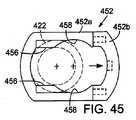
コントロールノブ432は、ノブ部分438と、近位筐体部分434内に延在する近位延長部440と、遠位筐体部分436内に延在する遠位延長部442とを備えることができる。図41に最もよく示すように、ハンドルアセンブリが組み立てられた時に、ノブ部分438は、近位筐体部分と遠位筐体部分との間に載置される。近位筐体部分434は、近位延長部440内の対応する環状溝446(図44)内に延在する、近位筐体部分の環状フランジ444を介して、近位延長部440に固定することができる。同様に、遠位筐体部分は、遠位延長部442内の対応する環状溝450(図44)内に延在する、遠位筐体部分の環状フランジ448を介して、遠位延長部442に固定することができる。 The
制御ノブ432は、遠位延長部442の上に載置される、ネジ係合ラッチ452を含むことができる。ネジ係合ラッチ452は、ユーザが、主要シャフト404のそれぞれの微調節または方向調節のために、ネジシャフト422を選択的に係合または係脱することを可能にするように動作可能である。さらに説明するように、ネジ係合ラッチ452(第1および第2のラッチ部分452a、452bを含むことができる)は、制御ノブの遠位延長部442内に形成された、上部および下部スロット454内に載置される。図45に最もよく示すように、ラッチ452は、スロット454を通って延在し、かつネジシャフト422の雄ネジに係合することができる、上部および下部の内向きに延在するフランジ456を有する。ラッチ452は、また、フランジ456に隣接する弓状の上部および下部の内表面458で形成することができる。ラッチ452は、フランジ456がスロット454から延在し、ネジシャフト422に係合する、係合位置と、湾曲表面458がスロット454内で整列させられ、ラッチがネジシャフト422から係脱される、係脱位置との間で、外側方向(両矢印460で示すように)に遠位延長部442の上で摺動可能である。バネ466は、バネの偏向に対して、ラッチ452を係合位置に保持するために、遠位延長部442と、ラッチ部分452bとの間に配置されることができる。図43に最もよく示すように、バネ466の一方の端部は、遠位延長部442の側面にあるノッチ468内に保持することができ、バネの他方の端部は、ラッチ部分452bの内部表面に対して支えるように設置することができる。 The
フランジ456がネジシャフト422のネジ山を係合するように、ラッチが係合位置にあるときに、制御ノブ432の回転は、筐体420内でネジシャフト422を縦方向に移動させる。主要シャフト404がネジシャフト422に固定されるため、ネジシャフトの縦方向移動は、弁カテーテルシャフト412の遠位端に載置された弁に対して、主要シャフト404およびシース406の対応する縦方向移動を引き起こす。制御ノブ432の回転は、制御された弁の配備のために、正確で制御された方法で、弁に対してシース406を移動させるために効果的である。湾曲表面458がスロット454内で整列させられるように、ラッチ452が係脱位置まで移動させられる時に、ラッチ452は、表面458によって画定される内径がネジシャフト422の外径を上回るという事実により、ネジシャフト422から係脱される。係脱位置においては、主要シャフト404は、シース406の位置の方向調節のために、制御ノブ432に対して自由に押すか、または引くことができる。オペレータは、筐体420から延在する主要シャフト404の部分を押すか、もしくは引くことによるか、または、フラッシュポート462(スロット464内で移動する)上で押すか、もしくは引くことによって、シース406の位置を調節することができる。 When the latch is in the engaged position such that the
弁カテーテルシャフト412は、患者の血管系の中を通る送達装置の誘導を促進するために、外科医が送達装置の遠位部分の湾曲または屈曲の量を誘導するか、または制御することを可能にするように構成されるガイドカテーテルを備えることができる。例えば、図41および42を参照すると、ハンドルアセンブリ408は、送達装置の遠位端の湾曲または屈曲の量を調節するように動作可能である、調節機構476を含むことができる。調節機構476は、筐体420内に延在する遠位延長部480を有する、回転可能な調節ノブ478を含むことができる。遠位延長部480は、中央摺動ロッド484の上の縦方向動作のために支持される、摺動ナット482に係合する雌ネジで形成された孔を有する。2つの支持ロッド486は、摺動ナット482の内表面と、摺動ロッド484の外表面との間に延在する。各支持ロッド486は、調節ノブ478に対する摺動ナット482の回転を制限するために、摺動ロッド484の外表面内および摺動ナット482の内表面内の細長いノッチ内で支持される。この配列に基づいて、ノブ478の回転(時計回りまたは反時計回りのいずれか)は、遠位および近位方向の摺動ロッド484に対して、摺動ナット482を縦方向に移動させる。少なくとも1つの引きワイヤ(図示せず)は、その近位端において、摺動ナット482に固定され、ハンドルアセンブリおよびシャフト412を通って延在し、その遠位端におけるシャフト412の遠位端に隣接する位置において固定される。送達装置の遠位端部分の湾曲を増加させるために、ノブ478は、摺動ナット482の近位方向の動作を引き起こすように回転させられ、それは、次に、送達装置の湾曲を増大するために引きワイヤを引く。送達装置の湾曲を減少させるために、調節ノブ478は、摺動ナット482を遠位方向に移動させるように反対方向に回転させられ、それは、送達装置の遠位端部分がそれ自体の弾力下で直線にすることを可能にするように、引きワイヤの張力を減少する。ガイドカテーテルの湾曲を制御するための調節機構のさらなる詳細は、米国特許出願公開第2008/0065011号および同第2007/0005131に開示され、それは、参照により本明細書に組み込まれる。 The
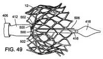
ここで、図47〜49を参照すると、人工弁10は、解放可能な接続を介して、弁カテーテルシャフト412の遠位端から延在する複数の縫合糸500を備える、弁カテーテルシャフト412の遠位端に固定することができる。各縫合糸500は、弁ステント12のフック部分502(図49)を通って延在し、そこを通って解放ワイヤ506が延在する、ループ504で形成される。解放ワイヤ506は、解放ワイヤをノーズカテーテルシャフトと平行整列に維持するために、ノーズカテーテルシャフト416の上に載置される、スペーサ508を通って延在することができる。解放ワイヤ506はさらに、弁カテーテルシャフト412、ハンドルアセンブリ408、およびコネクタ470を通って延在する(図41)。図48に最もよく示すように、縫合糸500は、弁カテーテルシャフトの先端部分510の口径部を通って延在することができ、弁カテーテルシャフトに対して、縫合糸500を固定するために、相互に縛り付けられるか、またはさもなければ、先端部分510に固定される。全体の弁10を図示せず、図示目的のために弁ステント12のみを図49に示すことに留意されたい。弁10は、図1〜2に示す構造と同様の構造を有することができる。 47-49, the
弁送達中に、弁は、半径方向に圧縮された状態でシース406内に載置される。シース406から弁を配備するために、シースは、制御ノブ432の回転(ラッチ452が係合位置にある時)、または主要シャフト404を近位方向に引くこと(ラッチ452が係脱位置にある時)によって、弁に対して後退させられる。図49に示すように、シース406の後退は、弁を露出し、それは、縫合糸500を介して弁カテーテルシャフト412に接続されたままの間、その機能的寸法に拡張させる。弁が弁カテーテルシャフト406に接続されたままであるため、拡張した弁の位置は、送達装置のハンドルアセンブリ408を移動させることによって調節することができる。弁が埋込のためのその所望位置にあると、弁は、解放ワイヤから縫合糸ループ504を解放するために、解放ワイヤ506を後退させ、それによって、弁のフック部分502から縫合糸500を解放することによって、解放することができる。解放ワイヤ506は、ハンドル上のコネクタ470から延在する、解放ワイヤの近位端上で引くことによって、後退させることができる(図41)。 During valve delivery, the valve is placed within the
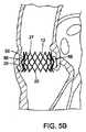
図50は、弁と弁カテーテルシャフト412との間の解放可能な接続を形成するための、さらなる接続技術を示す。この実施形態は、縫合糸500が先端部分510に対して固定されていないことを除き、図48に示す実施形態と同様である。その代わり、縫合糸の近位端部分512は、細長いシャフト、または弁カテーテルシャフト412から延在するワイヤ等の摺動解放機構(図示せず)に固着される。縫合糸500によって、弁がシャフト412に接続されている間に、解放機構は、遠位方向に移動され、弁のフック部分502の制御された拡張を可能にするように、縫合糸500内の緩みを増大することができる。解放機構は、解放機構の摺動動作を生じさせるように、ユーザが操作することができる、ハンドルアセンブリ上に位置する、摺動または回転ノブに動作可能に接続することができる。使用中、シース406は、弁に対して後退させられる。これは、それらが縫合糸500に依然として接続されているため、内向きに湾曲される、フック部分502を除き、ステント12が拡張することを可能にする。解放ワイヤ506を後退させる前に、摺動解放機構は、緩み500を増大させるために、遠位方向に移動させられ、ステントのフック部分502の制御された半径方向の拡張を可能にする。ステントが完全に拡張すると、解放ワイヤ506は、縫合糸500からステントのフック部分502を解放するために、後退させることができる。 FIG. 50 illustrates a further connection technique for forming a releasable connection between the valve and the
図51は、弁と弁カテーテルシャフト412との間の解放可能な接続を形成するための、接続技術の別の実施形態を示す。この実施形態においては、複数のテザー514(ステントの各フック部分502のうちの1つ)は、弁カテーテルシャフト412の遠位端から延在する。各テザー514の遠位端は、縫合糸518によって、各フック部分502に接続される、各付着要素516に固定される。各縫合糸518は、付着要素516にしっかりと固定される、1つの端部を有し、付着要素516のフック部分502および開口部520を通って延在し、その対向端部においてループ521を有する。各テザー514および付着要素516では、解放ワイヤ522は、シャフト412の遠位端から、各縫合糸518のループ521を通って延在する。テザー514の近位端は、シースから弁を配備するために、シース406が後退させられた後に、テザー514の緩みを増大させて、ステントフック部分502の制御された半径方向の拡張を可能にするように、遠位方向に移動することができる、摺動解放機構に固定することができる。ステントが完全に拡張した後に、各解放ワイヤ522は、各縫合糸518を解放するために、後退させることができ、次いで、それは、フック部分502を解放するように、開口部520を通って引き戻される。各解放ワイヤ522は、例えば、ハンドルアセンブリ408から延在する、各解放ワイヤの近位端上で引くことによって、独立して後退させることができる。あるいは、各解放ワイヤ522は、解放ワイヤを同時に一斉に後退させるように、後退または回転することができる、ハンドルアセンブリ上の共通のノブに接続することができる。 FIG. 51 illustrates another embodiment of a connection technique for forming a releasable connection between the valve and the
図52Aおよび52Bは、別の実施形態に従う、送達装置の遠位端部分600を図示する。送達装置600は、その遠位端においてノーズ部品604と、自己拡張型ステント弁608(図52Aおよび52Bに概略的に示す)を受容するための環状凹部分606とを有する、カテーテルシャフト602を含む。可撓性外側シース、またはスリーブ610は、カテーテルシャフト602および弁608の上を延在し、患者の血管系を通す送達のために、その圧縮状態の弁を凹部分606内に維持する。弁を被覆する、シース610の遠位端部分は、外側襞層612および内側襞層614を有する、襞部分である。内側襞層614の近位端616は、(例えば、接着剤を使用して)カテーテルシャフト602の外表面に固定される。使用中、外側襞層612は、矢印618が示すように、近位方向に引かれ、図52Bに示すように、弁を露出し、それが拡張することを可能にすることができる。スリーブ610は、望ましくは、弁608の外向きの拡張力に対して、円筒形状を維持するために十分な剛性を呈するが、外側襞層が内側襞層に対して引き戻されることを可能にするために十分な可撓性である。任意に、薄い流体層620は、襞層の隣接表面の摩擦を円滑かつ最小化するために、外側襞層612と内側襞層614との間に形成することができる。送達装置600の利点は、スリーブが引き戻されると、スリーブ610と弁608との間に生じた摩擦力がなく、そのため、その圧縮されたシースに入れられた状態から弁を解放するために、より少ない力がユーザによって必要とされるということである。 52A and 52B illustrate a
スリーブ610は、様々なポリマー(例えば、ナイロンもしくはPTFE)または金属(例えば、ニチノール)を含む、様々な材料のうちのいずれかから構成することができる。スリーブは、例えば、網状層、メッシュ層、非有孔層、またはそれらの組み合わせであってもよい、材料の1つ以上の層を備えることができる。図面には図示しないが、スリーブ610は、ユーザによる操作のために、送達装置のハンドルまで延在することができる。あるいは、スリーブ610は、ハンドルの手前で終端することができ、スリーブの近位端とハンドルとの間に延在する、1つ以上の引きワイヤに接続することができ、引きワイヤは、弁を配備させるために、外側襞層を引き戻すように、近位に引くことができる。 The
ノーズ部品604を、カテーテルシャフト602の部品として示すが、これは、必須ではない。さらなる実施形態においては、送達装置は、上述の実施形態に説明するように、シャフト602を通って延在し、ノーズ部品604を載置する内側ノーズカテーテルシャフトを含むことができる。また、本明細書に開示する、弁と送達装置との間の解放可能な接続を形成するための、様々な接続機構のうちのいずれかは、図52Aおよび52Bに示す実施形態に組み込むことができる。また、シャフト602は、バルーン膨張式弁(その場合では、弁は、自己拡張型である必要はない)をバルーン上に載置するために、シャフトの遠位端において、膨張式バルーンを有する、バルーンカテーテルのシャフトであってもよい。 Although
図53A〜53Eは、別の実施形態に従う、送達装置700を図示する。送達装置700は、外側カテーテルシャフト702と、外側シャフトを通って延在する内側カテーテルシャフト704とを備える。外側シャフト702の遠位端部分は、人工ステント弁706(概略的に示す)の上を延在し、患者の血管系を通して送達中に、それを圧縮状態に維持する、シースを備える。内側シャフト704の遠位端部分は、弁706のステントから延在して、弁と送達装置との間の解放可能な接続を形成する、1つ以上の嵌合延長アーム、または柱708と協働するように成形される。例えば、図示した実施形態においては、各柱708は、円環部分で終端する、直線部分を備え、シャフト704の遠位端部分は、各柱708を受容する、対応して成形された凹部710を有する。各凹部710は、各柱708の開口部714内に延在するように成形される、半径方向に延在する突出部712を含むことができる。図53Bに最もよく示すように、各凹部710および突出部712は、柱708の表面と凹部内の隣接する表面との間に小さい間隙を提供して、半径方向(すなわち、シャフト704の軸に垂直)に凹部から柱の挿入および除去を促進するように、寸法決定することができる。 53A-53E illustrate a
図53Aに図示するように、弁706が送達装置700内に充填される時に、弁の各柱708が凹部710内に配置されるように、弁は、柱および対応する凹部の形状に基づき、(近位および遠位方向の)シャフト704に対する軸運動に対して保持される。図53Dを参照すると、外側シャフト702が弁706を配備するために後退させられると、弁は、拡張することが可能になるが、弁の制御された送達のために、柱および対応する凹部によって形成された接続により、シースの遠位端からの「跳躍」に対して保持される。この段階において、部分的に配備した弁は、シャフト704によって、依然として保持され、外側シース702に対してシャフト704を近位方向に後退させることによって、外側シース702内に再度後退させることができる。図53Eを参照すると、外側シースが、柱708を超えて近位方向に後退させられる時に、弁ステントの拡張力は、柱を凹部710から半径方向外向きに拡張させ、それによって、シャフト704から弁を完全に解放する。 As illustrated in FIG. 53A, the valve is based on the shape of the column and the corresponding recess so that each
3つの柱708および対応する凹部710を、図示した実施形態において示すが、任意の数の柱および凹部を使用することができる。さらに、柱および凹部は、四角形、楕円形、長方形、三角形、またはそれらの様々な組み合わせ等の様々な他の形状を有することができる。柱は、弁ステントを形成するために使用する、同一の材料(例えば、ステンレス網またはニチノール)から形成することができる。あるいは、柱は、縫合材料等の剛性の少ない材料から形成されたループであってもよい。ループは、弁ステントに固定され、凹部710内で受容されるように寸法決定される。 Three
図54A〜54Dは、図53A〜53Eに示す送達装置と同様の送達装置800を図示する。送達装置800は、回転可能なノブ804を有するハンドル部分802と、ハンドル部分802から延在する外側カテーテルシャフト806と、ハンドル部分から外側カテーテルシャフト806を通って延在する内側カテーテルシャフト808を含む。内側カテーテルシャフト808の遠位端は、環状凹部812および複数の軸方向に延在する角度離間した凹部814で形成される、端部品810を含む。凹部812、814は、弁のステント(図54A〜54Dにおいて図示せず)から延在する、T型柱816を受容するように、寸法決定され、かつ成形される。各柱816は、対応する凹部814内に受容される、軸方向に延在する部分816aと、環状凹部812内に受容される、横方向の端部分816bとを有する。外側シャフト806は、弁の伝達中に、端部品812および弁の上を延在するように、寸法決定され、かつ成形される、シース818を含む。 54A-54D illustrate a
外側シャフト806は、図40〜42に示す実施形態に関連して上記に説明するように、ノブ804の回転時に、内側シャフト808に対して、外側シャフト806およびシース818の縦方向動作を生じるように、ノブ804に動作可能に接続される。使用中、弁は、弁の柱816を凹部812、814内に定置させ、かつ弁を圧縮状態で維持するために、弁の上を延在するようにシースを遠位に移動させることによって、送達のために載置される。弁を埋め込むための標的部位、またはその付近において、ノブ804は、弁に対してシース818を後退させるように回転させられる。弁を配備するために、シースが後退させられると、弁は、拡張することが可能になるが、弁の制御された送達のために、柱および対応する凹部によって形成された接続によって、シースの遠位端からの「跳躍」に対して保持される。この段階において、部分的に配備した弁は、端部品810によって、依然として保持され、弁に対して、シャフト806を遠位に移動させることによって、シース内に再度後退させることができる。シースが柱816を超えて近位方向に後退させられる時に、弁ステントの拡張力は、凹部812、814から柱を半径方向外向きに拡張させ、それによって、端部品810から弁を完全に解放する。 The
図55A〜55Bは、カテーテルまたは同様のデバイス、例えば、人工心臓弁を送達し、かつ埋め込むための送達装置を体内に導入するために使用することができる、900で示す、導入器の一実施形態を示す。導入器900は、細長い管、または体内のチャネル(例えば、血管)の中への挿入のために寸法決定された、シャフト902を含む。管902は、筐体904から延在する。カテーテル(図55A〜55Bにおいて図示せず)を受容するための中心開口部908を有する、キャップ部分906は、筐体の近位端に載置される。シール910は、キャップ部分の対向面と筐体との間に捕集される。シールは、シリコーンゴム等の任意の好適な弾性材料、または様々な他の好適なエラストマのうちのいずれかから作製することができる。シールは、キャップ部分の開口部908と整列される、中心開口部912と、管902の管腔とを有する。シール910は、体内へのカテーテルの挿入中の血液喪失を最小化するために、カテーテルの表面に係合している間に、カテーテルが開口部912を通って挿入されることを可能にするように寸法決定される。筐体内に位置する、管902の近位端部分は、筐体904の内表面上の対応する雌ネジに係合する、雄ネジ部分914を有する。ネジ山部分914の近位延長部分916は、シール910に接触する。ネジ山部分914は、好適な接着剤等を用いて、管902に固着される。さらなる実施形態においては、管およびネジ山部分は、ネジ山部分が管上に直接形成される、単一または単一部品構造を有することができる。 55A-55B shows an embodiment of an introducer, shown at 900, that can be used to introduce a catheter or similar device, such as a delivery device for delivering and implanting a prosthetic heart valve, into the body. Indicates.
筐体904は、両矢印917に示すように、シール910の開口部912を選択的に膨満するか、またはそれに接触するように、管902に対して縦方向に移動可能である。図示した実施形態における筐体904は、管に対して筐体の縦方向動作を生じるように、管902に対して回転可能である。筐体が近位位置(図55A)から遠位位置(図55B)まで移動すると、シール910は、シール開口部912を第1の直径D1から第2のより大きい直径D2まで膨満させる、延長部分916に対して伸展する。上述のように、導入器900を使用して、体内への弁送達装置(例えば、上述の送達装置100)の導入を補助することができる。使用中、管902は、従来の方法を用いて事前に膨満することができる、血管(例えば、大腿動脈)の中に挿入される。次いで、筐体904は、シールの開口部を、管902の管腔内への圧縮弁(および弁を被覆する任意のシース)の通過を可能にするために十分大きい直径まで膨満するように、遠位に移動される。弁(または送達装置の最大部分)がシールを通過した後に、筐体は、筐体を近位に移動させて、シール開口部912がその膨満前の寸法まで再度収縮することを可能にするように、反対方向に回転される。この状態においては、シールは、送達装置の外表面に係合して、送達装置の外表面に沿った血液喪失を予防または少なくとも最小化する。 The
図56A〜56Bは、別の実施形態に従う、導入器1000を示す。この実施形態は、図55A〜55Bの実施形態と多くの類似点を共有する。したがって、図55A〜55Bの対応する構成要素と同一である、図56A〜56Bの構成要素は、同一の各参照番号を有し、さらに説明しない。導入器1000は、導入器900とは異なり、導入器1000の管902は、筐体904の内表面に摺動可能に係合する、外部部分1002を含む。したがって、図56Bに図示するように、筐体904を回転させるよりはむしろ、筐体は、単に、シール開口部912を膨満させるために、管902に対して、遠位に押すことができる。筐体904からの手動圧力の除去は、シール開口部を収縮させるように、シール910の弾力性が筐体を近位に引き戻すことを可能にする。 56A-56B show an
図57Aおよび57Bは、体内の血管の中への送達装置(例えば、弁送達装置)の挿入を促進するために使用することができる、1100で示す、統合導入器シースおよび充填器アセンブリを示す。導入器シースは、本明細書に説明する送達装置の実施形態等の、人工弁を埋め込むために使用される送達装置との使用に特に適する。導入器シースは、様々な種類の腔内デバイス(例えば、ステント、ステント移植弁)を置換するための他の種類の送達装置を、多くの種類の血管非血管性体内管腔(例えば、静脈、動脈、食道、胆道管、腸、尿道、卵管、他の内分泌または外分泌管等)内に導入するために使用することもできる。 57A and 57B show an integrated introducer sheath and filler assembly, shown at 1100, that can be used to facilitate insertion of a delivery device (eg, a valve delivery device) into a blood vessel in the body. The introducer sheath is particularly suitable for use with a delivery device used to implant a prosthetic valve, such as the delivery device embodiments described herein. Introducer sheaths replace other types of delivery devices for replacing various types of intraluminal devices (e.g., stents, stent-grafts) with many types of vascular non-vascular body lumens (e.g., veins, Arterial, esophagus, biliary tract, intestine, urethra, fallopian tube, other endocrine or exocrine tracts, etc.).
従来の導入器シースは、典型的には、バルーンカテーテル上に載置された弁に、閉塞されていない通路を提供するように、シース筐体内のシールを通って挿入される、管状充填器を必要とする。充填器は、導入器シースの近位端から延在し、それによって、その使用長を増大させ、体内に挿入することができる、送達装置の使用可能な使用長を減少させる。導入器シース1100は、シースの使用長を減少させ、したがって、体内に挿入することができる、送達装置の使用可能な使用長を増大させるために、シース筐体内に収容された、統合充填器管を含む。また、従来の導入器シースは、キャップと、典型的には、弁がシャフトの遠位端上に載置される前に、導入器シースから除去され、送達装置上にシャフト上に事前充填され、次いで、弁および送達装置がシース筐体内に挿入されると、シース筐体に再度取り付けられる、各シールとを含む。手順は、さもなければ、弁が捲縮状態でシャフト上に載置されている間に、シールの開口部を通って押し出される場合に生じ得る、人工弁への損傷を防止するために、この方法で実施される。いくつかの場合においては、シールは、キャップ内のその目的位置から脱落する可能性があり、それは、シールへの損傷を生じる可能性がある。そのような場合においては、ユーザは、シールの修復または置換のために、キャップおよびシールアセンブリを分解する必要があり得る。 Conventional introducer sheaths typically include a tubular filler that is inserted through a seal in the sheath housing to provide an unoccluded passage for a valve mounted on a balloon catheter. I need. The filler extends from the proximal end of the introducer sheath, thereby increasing its use length and reducing the usable use length of the delivery device that can be inserted into the body.
図示したアセンブリ1100は、シール筐体1102と、筐体から遠位に延在する管状スリーブ1104とを含む。シール筐体1102は、図示した実施形態に示すように、弁1106、ディスク1108、および止血弁1110等の1つ以上の封止弁を収容する。弁は、同様の生体適合性材料も使用することができるが、望ましくは、ポリイソプレン等の弾性の生体適合性材料から加工される。弁1106、1108、1110は、米国特許第6,379,372号において、さらに示され、説明され、それは、参照により本明細書に組み込まれる。スペーサ1112は、クロススリット弁1106とシール筐体の近位端との間に挿入することができる。 The illustrated
シール筐体の長さに沿って、縦方向に移動するように適合される、部品1114は、シール筐体の近位端に結合される。図示した実施形態においては、端部品は、シール筐体1102の外表面上の雄ネジ部分1118に係合する、雌ネジ1116で形成された、管状本体を有する。したがって、端部品1114の回転は、シール筐体に対して、同一の内向きおよび外向きに移動する。端部品1114は、中央開口1120を有する、その近位端においてキャップ部分1119と、端部品の内側に固着された、細長い充填器管1122とを有する。開口部1120および充填器管1122は、送達装置上に載置された弁(または、他の人工弁)の通過を可能にするように寸法化される。端部品1114はまた、開口部1120と整列する、中心開口部1126を有する、シール1124を収容する。シール1124は、それが導入器シースアセンブリ1100内に挿入される時に、送達装置の外表面に密封的に係合する。 A
上述のように、端部品1114は、シール筐体1102に対して、内向きおよび外向きに調節することができる。図57Aに示す延在位置から、図57Bに示す後退位置まで、端部品1114を調節することによって、充填器管1122がシール1106、1108、1110を通って移動し、弁が導入器シースを通過するための閉塞されていない通路を提供する。従来の導入器シースのように、充填器管は、端部品の裏に延在しないため、充填器管は、血管系の中に挿入することができる、送達装置の使用可能な使用長を減少させない。また、キャップ部分1119は、縦方向動作のために、端部品1114上に摺動的に載置され、かつシール1124に係合し、それを伸張させるように位置する、内側管状部分1128を有する。キャップ部分1119が、端部品に対して遠位に押し出される時に、管状部分1128は、送達装置および捲縮した弁にアセンブリ内への閉塞されていない通路を提供するために、シール1124を伸張させ、シール開口部1126を、第1の直径(図57A)から第2のより大きい直径(図57B)まで膨満させる。従来の導入器シースとは対照的に、キャップおよびその各シールは、弁を送達装置上に載置する前に、シースから除去され、送達装置上に事前に充填される必要はない。理解することができるように、図示した実施形態の構成は、シース内への送達装置の導入を促進し、かつ、充填プロセス中の潜在的なシールの脱落を回避する。 As described above, the
使用中、図57Aに示す延在位置にある導入器シース1100は、挿入されたガイドワイヤ(図示せず)の上に定置され、スリーブ1104が所望の距離だけ本体容器内に延在するまで、その上を前進させることができる。次いで、キャップ部分は、弁を充填器管1122内に位置付けるために、シール開口部1126を通る通路を可能にするように、シール1124を膨満するために、遠位に押し出すことができる。その後、キャップ部分は、シールの弾力性(図57A)下で近位位置に再度移動することを可能にすることができ、それによって、シール1124が送達装置の外側シャフトの周辺に流体密封を形成することを可能にする。その後、端部品1114は、管1122を弁1106、1108、1110(図57B)を通って摺動させるために回転させられ、したがって、スリーブ1104の管腔と連通する送達装置、およびスリーブが挿入される本体容器を定置する。有利には、このアプローチは、充填プロセスを簡略化し、シース内に弁を充填するために必要とされる、工程および部品の数を減少させる。 In use, the
導入器シース1100の代替的実施形態においては、シール筐体1102は、端部品1114上の雄ネジに係合する雌ネジを有することができる。端部品は、前述のように、充填器管1122の位置を調節するために回転することができる。また、シール筐体上のネジ山および端部品のピッチは、封止弁を通って充填器を延在させるために必要とされる、回転動作の量を変化させるために異なってもよい。別の実施形態においては、端部品1114は、端部品を回転させることなく、押し、引くことによって、シール筐体の長さに沿って、摺動可能に位置付け可能であってもよい。別のさらなる実施形態においては、キャップ部分は、図56Aおよび56Bの実施形態に示すように、シールを膨満するために、キャップ部分の縦方向移動を生じるように、端部品1114に対して回転可能であってもよい。 In an alternative embodiment of the
公知の導入器シースは、典型的には、約0.010〜0.015インチの放射状壁の厚さを有するポリマー管から作製されるスリーブを用いる。図58Aは、公知のデバイスと比較してさらに薄い壁厚を有する薄い金属管状層を有する、1200で示す導入器シースの別の実施形態を示す。具体的な実施形態においては、シース1200の壁厚は、約0.0005〜約0.002インチである。導入器シース1200は、近位に位置する筐体、またはハブ1202と、遠位に延在するスリーブまたはカニューラ1204とを含む。筐体1202は、上記に詳細に説明するように、血液喪失を最小化するために、シールまたは一連のシールを収容することができる。スリーブ1204は、ニチノールまたはステンレス網等の金属または金属合金から形成され、望ましくは、スリーブに所望程度の屈曲を付与するために、一連の円周方向に延在するか、またはらせん方向に延在するスリットまたは開口部で形成される、管状層1206を含む。 Known introducer sheaths typically use a sleeve made from a polymer tube having a radial wall thickness of about 0.010 to 0.015 inches. FIG. 58A shows another embodiment of an introducer sheath, indicated at 1200, having a thin metal tubular layer having a thinner wall thickness compared to known devices. In a specific embodiment, the wall thickness of the
図58Bに示すように、例えば、管状層1206は、交互円形バンド1207の「Iビーム」パターン、および隣接バンド1207を接続する、軸方向に延在する接続部分1210を有する開口部1208で形成(例えば、レーザ切断)される。2つの隣接バンド1207は、図示した実施形態に示すように、スリーブの軸の周辺で相互から90度角度離間した4つの接続部分1210等の、複数の角度離間した接続部分1210によって接続することができる。スリーブ1204は、それが、捩れるか、または座屈せずに蛇行通路を通って押し出されると、スリーブが屈曲することを可能にするために十分な可撓性を呈する。図59は、レーザ切断するか、またはさもなければ、管状層1206内に形成することができる、開口部の別のパターンを示す。図59の実施形態における管状層は、隣接バンド1212を接続し、スリーブの長さに沿ってらせんパターンに配列される接続部分1216を有する、交互バンド1212および開口部1214のパターンを示す。さらなる実施形態においては、バンドおよび開口部のパターン、および/またはバンドおよび/または開口部の幅は、その長さに沿ってスリーブの剛性を変化させるために、スリーブの長さに沿って異なってもよい。例えば、バンドの幅は、スリーブの近位端付近においてより高い剛性、および遠位端付近においてより高い可撓性を提供するように、スリーブの近位端から遠位端まで減少してもよい。 As shown in FIG. 58B, for example, the
図60に示すように、スリーブは、管状層1206の上を延在し、スリーブと、スリーブが挿入される容器壁との間の摩擦を減少するような低摩擦材料から作製される薄い外層1218を有することができる。スリーブはまた、管状層1206の内表面を被覆し、スリーブと、スリーブ内に挿入される送達装置との間の摩擦を減少するような低摩擦材料から作製される、薄い内層1220を有することができる。内層および外層は、PET、PTFE、および/またはFEP等の好適なポリマーから作製することができる。 As shown in FIG. 60, the sleeve extends over the
具体的な実施形態においては、管状層1206は、約0.0005インチ〜約0.002インチの範囲の放射状壁厚を有する。そのため、スリーブは、公知のデバイスよりも、約1〜2Frの小さい外径で提供することができる。スリーブ1204の比較的より小さい形状は、使用の利便性を向上し、動脈壁の断裂を介する患者の怪我のリスクを低減し、高度に石灰化された動脈、蛇行経路または小さい直径の血管を有する患者に対して、最小の侵襲性の手順(例えば、心臓弁置換)の潜在的な使用を増大させる。 In a specific embodiment,
さらなる実施形態においては、送達装置は、トルクシャフトを回転させるために手動動力源を使用するノブまたは同様の機構の代わりに、またはそれの他に、トルクシャフトの回転を生じさせるために、動力源と共に提供することができる。例えば、ハンドル部分308(図35)は、ギア348に接続され、それに回転動作を伝達する小さい電気モータを収容することができる。この方法で、ユーザは、ハンドル部分のモータを単に起動することによって、トルクシャフト312の回転(弁を10をシースから抜く)を生じさせることができる。モータは、望ましくは、トルクシャフトが両方向に回転することができるように双方向モータである。あるいは、動力源は、トルクシャフトを回転させるように構成される油圧動力源(例えば、油圧ポンプ)、または空気(空気動作型)動力源であってもよい。 In a further embodiment, the delivery device may include a power source to effect rotation of the torque shaft instead of, or in addition to, a knob or similar mechanism that uses a manual power source to rotate the torque shaft. Can be provided with. For example, the handle portion 308 (FIG. 35) can accommodate a small electric motor that is connected to the
別の実施形態においては、動力源(例えば、電気、油圧、または空気動力源)は、シャフトに動作可能に接続することができ、それは、次に弁10に接続される。動力源は、シースから弁を前進させるために、正確で制御された方法で、弁シースに対して、シャフトを遠位方向に縦方向に往復運動させるように構成される。あるいは、動力源は、シースから弁を配備するために、弁に対して、シースを近位方向に縦方向に往復運動させるためにシースに動作可能に接続されてもよい。 In another embodiment, a power source (eg, an electrical, hydraulic, or pneumatic power source) can be operably connected to the shaft, which is then connected to the
開示した本発明が適用され得る、多くの潜在的な実施形態を考慮して、図示した実施形態は、本発明の所望の実施例のみであり、本発明の範囲を限定するものとして受け取られてはならないことを認識されたい。むしろ、本発明の範囲は、以下の請求項によって定義される。したがって、我々は、我々の発明のすべてが、これらの請求項の範囲および精神に含まれることを主張する。 In view of the many potential embodiments to which the disclosed invention may be applied, the illustrated embodiments are only preferred examples of the invention and are taken as limiting the scope of the invention. Recognize that it must not. Rather, the scope of the present invention is defined by the following claims. We therefore claim that all our inventions fall within the scope and spirit of these claims.
Claims (31)
Translated fromJapanese可撓性トルクシャフトを備えるカテーテルであって、該トルクシャフトは、該患者の血管系を通って延在するように適合され、該トルクシャフトは、該人工弁に結合される遠位端部分を有する、カテーテルと、
該弁を受容するように構成される弁シースであって、該弁は、該弁が該患者の血管系を通して該心臓まで送達するために該トルクシャフトの該遠位端に結合されるときに、半径方向に圧縮された状態にある、弁シースと
を備えており、
該トルクシャフトの回転は、該シースと該弁との間の相対的な縦方向移動を効果的に引き起こすことにより、該心臓内での配備のために該シースから該弁を前進させる、心臓弁送達装置。A heart valve delivery device for delivering a prosthetic heart valve through a patient's vasculature, comprising:
A catheter comprising a flexible torque shaft, wherein the torque shaft is adapted to extend through the patient's vasculature, the torque shaft having a distal end portion coupled to the prosthetic valve. Having a catheter;
A valve sheath configured to receive the valve when the valve is coupled to the distal end of the torque shaft for delivery through the patient's vasculature to the heart. A valve sheath in a radially compressed state, and
The rotation of the torque shaft advances the valve from the sheath for deployment within the heart by effectively causing a relative longitudinal movement between the sheath and the valve. Delivery device.
前記保持機構は、第1のフォークと、第2のフォークとを備え、該第1のフォークは、複数の突起部を有し、該複数の突起部の各々は、該ステントのそれぞれの柱の端部を受容する開口部を有し、該第2のフォークは、複数の突起部を有し、該複数の突起部の各々は、該ステントのそれぞれの柱の開口部を通って延在し、それによって、該ステントを該保持機構に接続し、該第2のフォークは、該ステント柱の該開口部から該第2のフォークの該突起部を除去して、該弁と該保持機構との間の接続を解放するように、該第1のフォークに対して縦方向に移動可能である、請求項10に記載の装置。The valve comprises a stent having a plurality of angularly spaced columns, each of the columns having a respective opening in an end portion thereof;
The holding mechanism includes a first fork and a second fork, and the first fork has a plurality of protrusions, and each of the plurality of protrusions corresponds to each column of the stent. An opening for receiving an end, the second fork having a plurality of protrusions, each of the plurality of protrusions extending through an opening in a respective column of the stent. Thereby connecting the stent to the retention mechanism, wherein the second fork removes the protrusion of the second fork from the opening of the stent post, the valve and the retention mechanism; The apparatus of claim 10, wherein the apparatus is movable longitudinally relative to the first fork to release a connection between the first fork.
前記装置は、該第1のカテーテルの前記トルクシャフトを通って延在する細長いシャフトを備える第2のカテーテルをさらに備え、該シャフトは、相互に対して縦方向に移動可能であり、
第1のフォークが、該第1のカテーテルの前記遠位端部分に結合され、該第2のフォークが、該第2のカテーテルの前記遠位端部分に結合されることにより、該第2のフォークを同一方向に移動させることに効果的であり、それにより、近位方向への該第2のカテーテルの該シャフトの縦方向移動が、前記ステント柱の前記開口部からそれの突起部を除去して、前記弁と前記保持機構との間の前記接続を解放する、請求項12に記載の装置。The catheter comprises a first catheter;
The apparatus further comprises a second catheter comprising an elongate shaft extending through the torque shaft of the first catheter, the shaft being movable longitudinally relative to each other;
A first fork is coupled to the distal end portion of the first catheter and the second fork is coupled to the distal end portion of the second catheter, thereby It is effective to move the fork in the same direction so that the longitudinal movement of the shaft of the second catheter in the proximal direction removes its protrusion from the opening of the stent column. 13. The apparatus of claim 12, wherein the apparatus releases the connection between the valve and the retention mechanism.
遠位端部分を有する少なくとも1つの細長いカテーテルと、
該弁を該カテーテルの該遠位端に結合する弁保持機構と
を備えており、
該保持機構は、第1のフォークと、第2のフォークとを備え、各フォークは、複数の角度離間した突起部を有し、第1のフォークの各突起部は、該第2のフォークの対応する突起部と協働して、該弁の該ステントとの解放可能な接続を形成し、該第2のフォークは、該突起部および該ステントによって形成された各接続を解放するように、該第1のフォークに対して移動可能である、心臓弁送達装置。A heart valve delivery device for delivering a prosthetic stent heart valve through a patient's vasculature comprising:
At least one elongate catheter having a distal end portion;
A valve retention mechanism that couples the valve to the distal end of the catheter;
The holding mechanism includes a first fork and a second fork, each fork having a plurality of angularly spaced protrusions, and each protrusion of the first fork is formed on the second fork. In cooperation with corresponding protrusions to form a releasable connection of the valve with the stent, and the second fork releases each connection formed by the protrusion and the stent; A heart valve delivery device that is movable relative to the first fork.
前記第1のフォークの各突起部は、該ステントのそれぞれの柱の端部分を受容する開口部を有し、該第2のフォークは、複数の突起部を有し、各突起部は、該ステントのそれぞれの柱の開口部を通って延在するように寸法決定され、それにより、該ステントと前記保持機構との間の解放可能な接続を形成し、該第2のフォークは、該ステント柱の開口部から該第2のフォークの該突起部を除去して、該突起部と該ステントとによって形成された各接続を解放するために、該第1のフォークに対して縦方向に移動可能である、請求項15に記載の装置。The stent has a plurality of angularly spaced columns, each column having a respective opening at its end portion;
Each protrusion of the first fork has an opening for receiving an end portion of each column of the stent, the second fork has a plurality of protrusions, and each protrusion has the Dimensioned to extend through an opening in each post of the stent, thereby forming a releasable connection between the stent and the retention mechanism, wherein the second fork is Move longitudinally relative to the first fork to remove the protrusion of the second fork from the column opening and release each connection formed by the protrusion and the stent. The device according to claim 15, which is possible.
半径方向に拡張可能かつ圧縮可能な支持枠であって、該支持枠は、流入端部および流出端部を備えるメッシュ構造を形成するように、互に相互接続された複数の支柱部材を備え、該メッシュ構造は、第1の位置において第1の直径を有する膨満した中間部分を備え、該中間部分は、第2の位置において第2のより小さい直径を有する流入端部分を形成するように、該流入端部に向かう方向に先細りになる、支持枠と、
それぞれの流入端部分および流出端部分を有する複数の弁尖であって、該弁尖の該流入端部分は、該メッシュ構造の流入端部分において該メッシュ構造の内側に固定され、該弁尖の該流出端部分は、該メッシュ構造の該流出端部において該メッシュ構造の内側に固定される角度離間した交連を画定する、弁尖と
を備える、弁。A prosthetic heart valve for implantation at an implantation site having an annulus, the valve comprising:
A radially expandable and compressible support frame comprising a plurality of strut members interconnected to each other so as to form a mesh structure having an inflow end and an outflow end; The mesh structure comprises a bulged intermediate portion having a first diameter at a first location, the intermediate portion forming an inflow end portion having a second smaller diameter at a second location, A support frame that tapers in a direction toward the inflow end;
A plurality of leaflets having respective inflow end portions and outflow end portions, wherein the inflow end portions of the leaflets are secured to the inside of the mesh structure at the inflow end portions of the mesh structure; A valve leaflet that defines an angularly spaced commissure that is secured to the inside of the mesh structure at the outflow end of the mesh structure.
該弁に接続されるように適合される近位端および遠位端を有する第1の細長いシャフトと、
該第1のシャフト上に延在する第2の細長いシャフトであって、該第2の細長いシャフトは、該弁が半径方向に圧縮された状態であるときに、該弁上に延在するように構成されるシースを備える近位端部分および遠位端部分を有する、第2の細長いシャフトと、
該第1および第2のシャフトの該近位端に結合されるハンドルであって、該ハンドルは、回転可能なアクチュエータ、および該アクチュエータに動作可能に接続され、該第2のシャフトの該近位端に接続されるネジを備え、該アクチュエータは、該ネジの雄ネジに係合するように構成され、該アクチュエータの回転は、該第1のシャフトに対する該ネジおよび第2のシャフトの縦方向移動を引き起こすことにより、該弁に対してシースを後退させる、ハンドルと
を備えており、
該アクチュエータは、ラッチであって、該ラッチが該ネジの該ネジ山に係合する係合位置と、該ラッチが該ネジの該ネジ山から係脱される係脱位置との間で移動可能である、ラッチを備えることにより、該ラッチが該係合位置にあるときには、該アクチュエータの回転は、該ネジの縦方向移動を引き起こし、該ラッチが該係脱位置にあるときには、該アクチュエータの回転を伴わずに、該ネジを該第1のシャフトに対して縦方向に移動させることができる、送達装置。A delivery device for delivering a prosthetic heart valve,
A first elongate shaft having a proximal end and a distal end adapted to be connected to the valve;
A second elongate shaft extending on the first shaft such that the second elongate shaft extends on the valve when the valve is radially compressed. A second elongate shaft having a proximal end portion and a distal end portion with a sheath configured to:
A handle coupled to the proximal ends of the first and second shafts, the handle operatively connected to the rotatable actuator, and the proximal of the second shaft; A screw connected to the end, the actuator being configured to engage a male screw of the screw, the rotation of the actuator being a longitudinal movement of the screw and the second shaft relative to the first shaft A handle for retracting the sheath relative to the valve by causing
The actuator is a latch and is movable between an engagement position where the latch engages the thread of the screw and an engagement / disengagement position where the latch is disengaged from the thread of the screw. The rotation of the actuator causes a longitudinal movement of the screw when the latch is in the engaged position, and the rotation of the actuator when the latch is in the disengaged position. A delivery device capable of moving the screw longitudinally with respect to the first shaft without the use of a screw.
遠位端部分を有する少なくとも1つの細長いカテーテルと、
該弁と該カテーテルの該遠位端部分との間の解放可能な接続を形成するように適合される解放可能な弁保持機構であって、該弁保持機構は、該カテーテルの該遠位端部分から延在する複数の縫合糸を備え、各縫合糸は、該ステントの一部分を通って延在してそれに係合し、一端においてループを有し、該弁保持機構は、各縫合糸の該ループを通って延在する細長い摺動可能な部材をさらに備えることにより、該弁を該カテーテルに接続し、該摺動可能な部材は、該縫合糸に対して後退可能であることにより、該摺動可能な部材から該ループを解放し、それによって、該弁と該カテーテルとの間の接続を解放する、弁保持機構と
を備える、送達装置。A delivery device for delivering a prosthetic heart valve having a stent comprising:
At least one elongate catheter having a distal end portion;
A releasable valve retention mechanism adapted to form a releasable connection between the valve and the distal end portion of the catheter, the valve retention mechanism comprising the distal end of the catheter A plurality of sutures extending from the portion, each suture extending through and engaging a portion of the stent, having a loop at one end, By further comprising an elongated slidable member extending through the loop, connecting the valve to the catheter, the slidable member being retractable relative to the suture; A delivery device comprising: a valve retention mechanism that releases the loop from the slidable member, thereby releasing a connection between the valve and the catheter.
該人工弁に結合されるように適合される遠位端部分を有する細長いカテーテルと、
弁シースであって、該シースは、該カテーテルの該遠位端部分に結合されると、半径方向に圧縮された状態の該弁の上に延在するように構成され、該シースは、該弁の上に延在する第1の管状襞層、および該第1の襞層の上に延在する第2の管状襞層から形成される襞状部分を備え、該第2の襞層は、該弁をシースから抜くために、該カテーテルおよび該弁に対して縦方向に移動可能である、弁シースと
を備える、送達装置。A delivery device for delivering a prosthetic heart valve,
An elongated catheter having a distal end portion adapted to be coupled to the prosthetic valve;
A valve sheath, wherein the sheath is configured to extend over the valve in a radially compressed state when coupled to the distal end portion of the catheter; A first tubular scissor layer extending over the valve and a scissor-like portion formed from a second tubular scissor layer extending over the first scissor layer, the second scissor layer comprising: A delivery device comprising: a valve sheath that is movable longitudinally relative to the catheter and the valve to withdraw the valve from the sheath.
該弁を患者の体内の埋込部位に送達する送達装置であって、該送達装置は、遠位端部分を有する細長いシャフトを備え、該遠位端部分は、該遠位端部分の外表面に形成され、該ステントの各柱を受容するように寸法決定される複数の凹部を有し、該送達装置は、該弁の上に延在し、各凹部内に配置された該柱を用いて、該弁を圧縮状態に保持するように寸法決定される外側シースをも備え、該シースおよび該シャフトは、該弁をシースから抜くために互に対して縦方向に移動可能であり、それによって、該弁が拡張することを可能にする、送達装置と
を備える、アセンブリ。A prosthetic valve comprising a self-expanding stent, the stent having a plurality of angularly spaced columns;
A delivery device for delivering the valve to an implantation site in a patient's body, the delivery device comprising an elongate shaft having a distal end portion, the distal end portion being an outer surface of the distal end portion And having a plurality of recesses dimensioned to receive each column of the stent, the delivery device extending over the valve and using the columns disposed within each recess And an outer sheath dimensioned to hold the valve in a compressed state, the sheath and the shaft being movable longitudinally relative to each other to withdraw the valve from the sheath, And a delivery device that allows the valve to expand.
該筐体の該内部孔から延在する細長い管状スリーブであって、該スリーブは、管腔を有し、患者の血管系に挿入されるように適合される、細長い管状スリーブと
を備える、導入器シース。A housing having an inner hole, a cap portion movable longitudinally on the housing, and an elastomer seal mounted on the cap portion and aligned with the inner hole; The cap portion is movable from a first position to a second position on the housing to radially extend the seal and enlarge the opening of the seal; and ,
An elongate tubular sleeve extending from the internal bore of the housing, the sleeve comprising a lumen and adapted to be inserted into a patient's vasculature; Instrument sheath.
Applications Claiming Priority (5)
| Application Number | Priority Date | Filing Date | Title |
|---|---|---|---|
| US9129308P | 2008-08-22 | 2008-08-22 | |
| US61/091,293 | 2008-08-22 | ||
| US12/429,040 | 2009-04-23 | ||
| US12/429,040US8652202B2 (en) | 2008-08-22 | 2009-04-23 | Prosthetic heart valve and delivery apparatus |
| PCT/US2009/054290WO2010022138A2 (en) | 2008-08-22 | 2009-08-19 | Prosthetic heart valve and delivery apparatus |
Publications (2)
| Publication Number | Publication Date |
|---|---|
| JP2012500665Atrue JP2012500665A (en) | 2012-01-12 |
| JP5677954B2 JP5677954B2 (en) | 2015-02-25 |
Family
ID=41697095
Family Applications (1)
| Application Number | Title | Priority Date | Filing Date |
|---|---|---|---|
| JP2011523957AActiveJP5677954B2 (en) | 2008-08-22 | 2009-08-19 | Prosthetic heart valve and delivery device |
Country Status (12)
| Country | Link |
|---|---|
| US (19) | US8652202B2 (en) |
| EP (9) | EP4066787B1 (en) |
| JP (1) | JP5677954B2 (en) |
| CN (1) | CN102196784B (en) |
| AU (1) | AU2009283878B2 (en) |
| CA (4) | CA2734190C (en) |
| DK (1) | DK4066787T3 (en) |
| ES (5) | ES2746037T3 (en) |
| FI (1) | FI4066787T3 (en) |
| MX (1) | MX2011001841A (en) |
| PL (1) | PL4066787T3 (en) |
| WO (1) | WO2010022138A2 (en) |
Cited By (56)
| Publication number | Priority date | Publication date | Assignee | Title |
|---|---|---|---|---|
| JP2015506194A (en)* | 2011-12-20 | 2015-03-02 | ボストン サイエンティフィック サイムド,インコーポレイテッドBoston Scientific Scimed,Inc. | Device for replacing a heart valve in a blood vessel |
| JP2015515887A (en)* | 2012-05-04 | 2015-06-04 | セント・ジュード・メディカル,カーディオロジー・ディヴィジョン,インコーポレイテッド | Apparatus and method for transcatheter heart valve delivery |
| JP2015516245A (en)* | 2012-05-16 | 2015-06-11 | イェーナヴァルヴ テクノロジー ゲゼルシャフト ミット ベシュレンクテル ハフツング | Catheter delivery system for introducing expandable heart substitute valve and medical device for treatment of heart valve defects |
| JP2015517376A (en)* | 2012-05-20 | 2015-06-22 | テル ハショマー メディカル リサーチ インフラストラクチャー アンド サーヴィシーズ リミテッド | Artificial mitral valve |
| JP2016506795A (en)* | 2013-02-04 | 2016-03-07 | トゥエルヴ, インコーポレイテッド | Hydraulic delivery system and related methods for prosthetic heart valve devices |
| JP2016508836A (en)* | 2013-03-05 | 2016-03-24 | メリット・メディカル・システムズ・インコーポレーテッド | Reinforcing valve |
| JP2016513569A (en)* | 2013-03-15 | 2016-05-16 | ナヴィゲート カーディアック ストラクチャーズ インコーポレイテッドNavigate Cardiac Structures, Inc. | Catheter-guided replacement valve device and method |
| JP2016518948A (en)* | 2013-05-20 | 2016-06-30 | エドワーズ ライフサイエンシーズ コーポレイションEdwards Lifesciences Corporation | Prosthetic heart valve delivery device |
| JP2016195827A (en)* | 2010-03-01 | 2016-11-24 | コリブリ ハート バルブ エルエルシーColibri Heart Valve Llc | Percutaneously deliverable heart valve and methods associated therewith |
| US9763780B2 (en) | 2011-10-19 | 2017-09-19 | Twelve, Inc. | Devices, systems and methods for heart valve replacement |
| KR20170108032A (en)* | 2015-01-28 | 2017-09-26 | 아오틱 이노베이션즈 엘엘씨 | Modular intra-aortic devices and methods of using such devices |
| US9901443B2 (en) | 2011-10-19 | 2018-02-27 | Twelve, Inc. | Prosthetic heart valve devices, prosthetic mitral valves and associated systems and methods |
| JP2018519880A (en)* | 2015-06-05 | 2018-07-26 | テンダイン ホールディングス,インコーポレイテッド | Advanced control of transvascular delivery of an artificial mitral valve |
| US10052204B2 (en) | 2011-10-19 | 2018-08-21 | Twelve, Inc. | Prosthetic heart valve devices, prosthetic mitral valves and associated systems and methods |
| JP2018523553A (en)* | 2015-07-20 | 2018-08-23 | トライケアス | Delivery device for self-expanding medical devices |
| US10238490B2 (en) | 2015-08-21 | 2019-03-26 | Twelve, Inc. | Implant heart valve devices, mitral valve repair devices and associated systems and methods |
| US10292820B2 (en) | 2013-11-12 | 2019-05-21 | St. Jude Medical, Cardiology Division, Inc. | Pneumatically power-assisted TAVI delivery system |
| US10390949B2 (en) | 2010-08-24 | 2019-08-27 | St. Jude Medical, Cardiology Division, Inc. | Staged deployment devices and methods for transcatheter heart valve delivery systems |
| US10500038B1 (en) | 2011-05-20 | 2019-12-10 | Tel Hashomer Medical Research Infrastructure And Services Ltd. | Prosthetic mitral valve, and methods and devices for deploying the prosthetic mitral valve |
| JP2020508812A (en)* | 2017-03-08 | 2020-03-26 | エピゴン | Delivery system for transcatheter prosthetic heart valve |
| US10631986B2 (en) | 2016-12-02 | 2020-04-28 | St. Jude Medical, Cardiology Division, Inc. | Transcatheter delivery system with transverse wheel actuation |
| KR20200044868A (en)* | 2017-08-23 | 2020-04-29 | 이씨피 엔트빅클룽스게젤샤프트 엠베하 | Apparatus for compressing the compressible part of the catheter pump |
| US10702380B2 (en) | 2011-10-19 | 2020-07-07 | Twelve, Inc. | Devices, systems and methods for heart valve replacement |
| US10751173B2 (en) | 2011-06-21 | 2020-08-25 | Twelve, Inc. | Prosthetic heart valve devices and associated systems and methods |
| JP2020526329A (en)* | 2017-07-13 | 2020-08-31 | テンダイン ホールディングス,インコーポレイテッド | Artificial heart valve and devices and methods for its delivery |
| US10758352B2 (en) | 2016-12-02 | 2020-09-01 | St. Jude Medical, Cardiology Division, Inc. | Transcatheter delivery system with two modes of actuation |
| JP2020531162A (en)* | 2017-08-22 | 2020-11-05 | エドワーズ ライフサイエンシーズ コーポレイションEdwards Lifesciences Corporation | Gear drive mechanism for heart valve carrier |
| JP2021500129A (en)* | 2017-10-18 | 2021-01-07 | エドワーズ ライフサイエンシーズ コーポレイションEdwards Lifesciences Corporation | Catheter assembly |
| US10898324B2 (en) | 2017-05-15 | 2021-01-26 | St. Jude Medical, Cardiology Division, Inc. | Transcatheter delivery system with wheel actuation |
| CN112423710A (en)* | 2018-07-18 | 2021-02-26 | W.L.戈尔及同仁股份有限公司 | Implantable medical device deployment system |
| US10993805B2 (en) | 2008-02-26 | 2021-05-04 | Jenavalve Technology, Inc. | Stent for the positioning and anchoring of a valvular prosthesis in an implantation site in the heart of a patient |
| US11065138B2 (en) | 2016-05-13 | 2021-07-20 | Jenavalve Technology, Inc. | Heart valve prosthesis delivery system and method for delivery of heart valve prosthesis with introducer sheath and loading system |
| US11129714B2 (en) | 2012-03-01 | 2021-09-28 | Twelve, Inc. | Hydraulic delivery systems for prosthetic heart valve devices and associated methods |
| US11185405B2 (en) | 2013-08-30 | 2021-11-30 | Jenavalve Technology, Inc. | Radially collapsible frame for a prosthetic valve and method for manufacturing such a frame |
| US11197754B2 (en) | 2017-01-27 | 2021-12-14 | Jenavalve Technology, Inc. | Heart valve mimicry |
| US11202704B2 (en) | 2011-10-19 | 2021-12-21 | Twelve, Inc. | Prosthetic heart valve devices, prosthetic mitral valves and associated systems and methods |
| US11337800B2 (en) | 2015-05-01 | 2022-05-24 | Jenavalve Technology, Inc. | Device and method with reduced pacemaker rate in heart valve replacement |
| US11357624B2 (en) | 2007-04-13 | 2022-06-14 | Jenavalve Technology, Inc. | Medical device for treating a heart valve insufficiency |
| JP2022542218A (en)* | 2019-07-29 | 2022-09-30 | エドワーズ ライフサイエンシーズ コーポレイション | Delivery system for medical implants |
| US11517433B2 (en) | 2010-09-17 | 2022-12-06 | St. Jude Medical, Cardiology Division, Inc. | Staged deployment devices and methods for transcatheter heart valve delivery |
| US11517431B2 (en) | 2005-01-20 | 2022-12-06 | Jenavalve Technology, Inc. | Catheter system for implantation of prosthetic heart valves |
| US11559398B2 (en) | 2017-06-02 | 2023-01-24 | Twelve, Inc. | Delivery systems with telescoping capsules for deploying prosthetic heart valve devices and associated methods |
| US11564794B2 (en) | 2008-02-26 | 2023-01-31 | Jenavalve Technology, Inc. | Stent for the positioning and anchoring of a valvular prosthesis in an implantation site in the heart of a patient |
| US11589981B2 (en) | 2010-05-25 | 2023-02-28 | Jenavalve Technology, Inc. | Prosthetic heart valve and transcatheter delivered endoprosthesis comprising a prosthetic heart valve and a stent |
| JP2023512643A (en)* | 2020-01-31 | 2023-03-28 | 4シー メディカル テクノロジーズ,インコーポレイテッド | Artificial Heart Valve Delivery System: Ball Sliding Attachment |
| JP2023512644A (en)* | 2020-01-31 | 2023-03-28 | 4シー メディカル テクノロジーズ,インコーポレイテッド | Artificial Heart Valve Delivery System: Paddle Mounting Feature |
| JP2023526321A (en)* | 2020-05-15 | 2023-06-21 | リバルブ ソリューションズ インコーポレイテッド | Devices, systems, and methods for collapsible expandable replacement heart valves |
| US11737873B2 (en) | 2017-04-18 | 2023-08-29 | Twelve, Inc. | Hydraulic systems for delivering prosthetic heart valve devices and associated methods |
| JP2023540505A (en)* | 2020-09-03 | 2023-09-25 | インキュービー8・メディカル・テクノロジーズ・リミテッド・ライアビリティ・カンパニー | Delivery systems and methods for prosthetic heart valves |
| US11833039B2 (en) | 2011-02-01 | 2023-12-05 | St. Jude Medical, Cardiology Division, Inc. | Leaflet suturing to commissure points for prosthetic heart valve |
| US12036115B2 (en) | 2019-08-14 | 2024-07-16 | Innovalve Bio Medical Ltd. | Atrioventricular valve replacement |
| US12121461B2 (en) | 2015-03-20 | 2024-10-22 | Jenavalve Technology, Inc. | Heart valve prosthesis delivery system and method for delivery of heart valve prosthesis with introducer sheath |
| US12171658B2 (en) | 2022-11-09 | 2024-12-24 | Jenavalve Technology, Inc. | Catheter system for sequential deployment of an expandable implant |
| JP2025514441A (en)* | 2022-04-29 | 2025-05-02 | 武漢唯柯医療科技有限公司 | Interventional Heart Valve Stent Delivery System |
| US12350156B2 (en) | 2018-11-14 | 2025-07-08 | Sheba Impact Ltd. | Atrioventricular valve repair |
| US12414854B2 (en) | 2010-05-20 | 2025-09-16 | Jenavalve Technology, Inc. | Catheter system for introducing an expandable stent into the body of a patient |
Families Citing this family (866)
| Publication number | Priority date | Publication date | Assignee | Title |
|---|---|---|---|---|
| US8036741B2 (en) | 1996-04-30 | 2011-10-11 | Medtronic, Inc. | Method and system for nerve stimulation and cardiac sensing prior to and during a medical procedure |
| EP0850607A1 (en) | 1996-12-31 | 1998-07-01 | Cordis Corporation | Valve prosthesis for implantation in body channels |
| US6454799B1 (en) | 2000-04-06 | 2002-09-24 | Edwards Lifesciences Corporation | Minimally-invasive heart valves and methods of use |
| US8366769B2 (en) | 2000-06-01 | 2013-02-05 | Edwards Lifesciences Corporation | Low-profile, pivotable heart valve sewing ring |
| EP1309289A2 (en) | 2000-08-18 | 2003-05-14 | Atritech, Inc. | Expandable implant devices for filtering blood flow from atrial appendages |
| US7556646B2 (en) | 2001-09-13 | 2009-07-07 | Edwards Lifesciences Corporation | Methods and apparatuses for deploying minimally-invasive heart valves |
| US6733525B2 (en) | 2001-03-23 | 2004-05-11 | Edwards Lifesciences Corporation | Rolled minimally-invasive heart valves and methods of use |
| US6893460B2 (en) | 2001-10-11 | 2005-05-17 | Percutaneous Valve Technologies Inc. | Implantable prosthetic valve |
| US9198786B2 (en) | 2003-09-03 | 2015-12-01 | Bolton Medical, Inc. | Lumen repair device with capture structure |
| US8292943B2 (en) | 2003-09-03 | 2012-10-23 | Bolton Medical, Inc. | Stent graft with longitudinal support member |
| US11259945B2 (en) | 2003-09-03 | 2022-03-01 | Bolton Medical, Inc. | Dual capture device for stent graft delivery system and method for capturing a stent graft |
| US20070198078A1 (en) | 2003-09-03 | 2007-08-23 | Bolton Medical, Inc. | Delivery system and method for self-centering a Proximal end of a stent graft |
| US11596537B2 (en) | 2003-09-03 | 2023-03-07 | Bolton Medical, Inc. | Delivery system and method for self-centering a proximal end of a stent graft |
| US7763063B2 (en) | 2003-09-03 | 2010-07-27 | Bolton Medical, Inc. | Self-aligning stent graft delivery system, kit, and method |
| US20050075725A1 (en) | 2003-10-02 | 2005-04-07 | Rowe Stanton J. | Implantable prosthetic valve with non-laminar flow |
| US9579194B2 (en)* | 2003-10-06 | 2017-02-28 | Medtronic ATS Medical, Inc. | Anchoring structure with concave landing zone |
| US8182528B2 (en) | 2003-12-23 | 2012-05-22 | Sadra Medical, Inc. | Locking heart valve anchor |
| EP2529699B1 (en) | 2003-12-23 | 2014-01-29 | Sadra Medical, Inc. | Repositionable heart valve |
| US7780725B2 (en) | 2004-06-16 | 2010-08-24 | Sadra Medical, Inc. | Everting heart valve |
| US7959666B2 (en) | 2003-12-23 | 2011-06-14 | Sadra Medical, Inc. | Methods and apparatus for endovascularly replacing a heart valve |
| US8343213B2 (en) | 2003-12-23 | 2013-01-01 | Sadra Medical, Inc. | Leaflet engagement elements and methods for use thereof |
| US9526609B2 (en) | 2003-12-23 | 2016-12-27 | Boston Scientific Scimed, Inc. | Methods and apparatus for endovascularly replacing a patient's heart valve |
| US7329279B2 (en) | 2003-12-23 | 2008-02-12 | Sadra Medical, Inc. | Methods and apparatus for endovascularly replacing a patient's heart valve |
| US20050137694A1 (en) | 2003-12-23 | 2005-06-23 | Haug Ulrich R. | Methods and apparatus for endovascularly replacing a patient's heart valve |
| US8603160B2 (en) | 2003-12-23 | 2013-12-10 | Sadra Medical, Inc. | Method of using a retrievable heart valve anchor with a sheath |
| US11278398B2 (en) | 2003-12-23 | 2022-03-22 | Boston Scientific Scimed, Inc. | Methods and apparatus for endovascular heart valve replacement comprising tissue grasping elements |
| US20120041550A1 (en) | 2003-12-23 | 2012-02-16 | Sadra Medical, Inc. | Methods and Apparatus for Endovascular Heart Valve Replacement Comprising Tissue Grasping Elements |
| US8828078B2 (en) | 2003-12-23 | 2014-09-09 | Sadra Medical, Inc. | Methods and apparatus for endovascular heart valve replacement comprising tissue grasping elements |
| US20050137687A1 (en) | 2003-12-23 | 2005-06-23 | Sadra Medical | Heart valve anchor and method |
| US7445631B2 (en) | 2003-12-23 | 2008-11-04 | Sadra Medical, Inc. | Methods and apparatus for endovascularly replacing a patient's heart valve |
| US8840663B2 (en) | 2003-12-23 | 2014-09-23 | Sadra Medical, Inc. | Repositionable heart valve method |
| US7381219B2 (en) | 2003-12-23 | 2008-06-03 | Sadra Medical, Inc. | Low profile heart valve and delivery system |
| US8579962B2 (en) | 2003-12-23 | 2013-11-12 | Sadra Medical, Inc. | Methods and apparatus for performing valvuloplasty |
| US7871435B2 (en) | 2004-01-23 | 2011-01-18 | Edwards Lifesciences Corporation | Anatomically approximate prosthetic mitral heart valve |
| JP2007527742A (en) | 2004-02-03 | 2007-10-04 | アトリア メディカル インク | Apparatus and method for controlling pressure in a living body |
| AU2004324043A1 (en) | 2004-10-02 | 2006-04-20 | Christoph Hans Huber | Methods and devices for repair or replacement of heart valves or adjacent tissue without the need for full cardiopulmonary support |
| US8608797B2 (en) | 2005-03-17 | 2013-12-17 | Valtech Cardio Ltd. | Mitral valve treatment techniques |
| US8333777B2 (en) | 2005-04-22 | 2012-12-18 | Benvenue Medical, Inc. | Catheter-based tissue remodeling devices and methods |
| US7780723B2 (en) | 2005-06-13 | 2010-08-24 | Edwards Lifesciences Corporation | Heart valve delivery system |
| US8951285B2 (en) | 2005-07-05 | 2015-02-10 | Mitralign, Inc. | Tissue anchor, anchoring system and methods of using the same |
| US8167932B2 (en) | 2005-10-18 | 2012-05-01 | Edwards Lifesciences Corporation | Heart valve delivery system with valve catheter |
| CA2881760C (en) | 2005-11-10 | 2017-06-13 | Arshad Quadri | Balloon-expandable, self-expanding, vascular prosthesis connecting stent |
| US20070213813A1 (en) | 2005-12-22 | 2007-09-13 | Symetis Sa | Stent-valves for valve replacement and associated methods and systems for surgery |
| WO2007083288A2 (en) | 2006-01-23 | 2007-07-26 | Atria Medical Inc. | Heart anchor device |
| EP1988851A2 (en)* | 2006-02-14 | 2008-11-12 | Sadra Medical, Inc. | Systems and methods for delivering a medical implant |
| WO2008013915A2 (en) | 2006-07-28 | 2008-01-31 | Arshad Quadri | Percutaneous valve prosthesis and system and method for implanting same |
| EP3360509B1 (en) | 2006-07-31 | 2022-06-22 | Syntheon TAVR, LLC | Sealable endovascular implants |
| US9585743B2 (en) | 2006-07-31 | 2017-03-07 | Edwards Lifesciences Cardiaq Llc | Surgical implant devices and methods for their manufacture and use |
| US9408607B2 (en) | 2009-07-02 | 2016-08-09 | Edwards Lifesciences Cardiaq Llc | Surgical implant devices and methods for their manufacture and use |
| EP2397108B1 (en) | 2006-09-08 | 2013-08-07 | Edwards Lifesciences Corporation | Apparatus for treating a defective heart valve |
| US11259924B2 (en) | 2006-12-05 | 2022-03-01 | Valtech Cardio Ltd. | Implantation of repair devices in the heart |
| US9883943B2 (en) | 2006-12-05 | 2018-02-06 | Valtech Cardio, Ltd. | Implantation of repair devices in the heart |
| US8236045B2 (en) | 2006-12-22 | 2012-08-07 | Edwards Lifesciences Corporation | Implantable prosthetic valve assembly and method of making the same |
| US11660190B2 (en) | 2007-03-13 | 2023-05-30 | Edwards Lifesciences Corporation | Tissue anchors, systems and methods, and devices |
| US9814611B2 (en) | 2007-07-31 | 2017-11-14 | Edwards Lifesciences Cardiaq Llc | Actively controllable stent, stent graft, heart valve and method of controlling same |
| US9566178B2 (en) | 2010-06-24 | 2017-02-14 | Edwards Lifesciences Cardiaq Llc | Actively controllable stent, stent graft, heart valve and method of controlling same |
| DE102007043830A1 (en) | 2007-09-13 | 2009-04-02 | Lozonschi, Lucian, Madison | Heart valve stent |
| US9848981B2 (en) | 2007-10-12 | 2017-12-26 | Mayo Foundation For Medical Education And Research | Expandable valve prosthesis with sealing mechanism |
| US8608792B2 (en)* | 2007-11-30 | 2013-12-17 | Scitech Produtos Medicos Ltda | Endoprosthesis and delivery system for delivering the endoprosthesis within a vessel of a patient |
| ES2781686T3 (en) | 2007-12-14 | 2020-09-04 | Edwards Lifesciences Corp | Leaflet Junction Frame for a Prosthetic Valve |
| US8157853B2 (en) | 2008-01-24 | 2012-04-17 | Medtronic, Inc. | Delivery systems and methods of implantation for prosthetic heart valves |
| AU2009206340B2 (en)* | 2008-01-24 | 2012-06-14 | Medtronic Vascular Inc. | Infundibular reducer device delivery system and related methods |
| CA2714062A1 (en) | 2008-01-24 | 2009-07-30 | Medtronic, Inc. | Stents for prosthetic heart valves |
| US9149358B2 (en)* | 2008-01-24 | 2015-10-06 | Medtronic, Inc. | Delivery systems for prosthetic heart valves |
| EP3912597A1 (en) | 2008-02-29 | 2021-11-24 | Edwards Lifesciences Corporation | Expandable member for deploying a prosthetic device |
| US8382829B1 (en) | 2008-03-10 | 2013-02-26 | Mitralign, Inc. | Method to reduce mitral regurgitation by cinching the commissure of the mitral valve |
| US20090276040A1 (en) | 2008-05-01 | 2009-11-05 | Edwards Lifesciences Corporation | Device and method for replacing mitral valve |
| US9061119B2 (en) | 2008-05-09 | 2015-06-23 | Edwards Lifesciences Corporation | Low profile delivery system for transcatheter heart valve |
| PL4223257T3 (en) | 2008-06-06 | 2024-09-23 | Edwards Lifesciences Corporation | LOW-PROFILE TRANSCATHETIC HEART VALVE |
| EP2296744B1 (en) | 2008-06-16 | 2019-07-31 | Valtech Cardio, Ltd. | Annuloplasty devices |
| US8323335B2 (en) | 2008-06-20 | 2012-12-04 | Edwards Lifesciences Corporation | Retaining mechanisms for prosthetic valves and methods for using |
| CN102076281B (en) | 2008-06-30 | 2014-11-05 | 波顿医疗公司 | Systems and methods for abdominal aortic aneurysm |
| US8652202B2 (en) | 2008-08-22 | 2014-02-18 | Edwards Lifesciences Corporation | Prosthetic heart valve and delivery apparatus |
| CN102292053A (en) | 2008-09-29 | 2011-12-21 | 卡迪尔克阀门技术公司 | Heart valve |
| EP3238661B1 (en) | 2008-10-10 | 2019-05-22 | Boston Scientific Scimed, Inc. | Medical devices and delivery systems for delivering medical devices |
| US8790387B2 (en)* | 2008-10-10 | 2014-07-29 | Edwards Lifesciences Corporation | Expandable sheath for introducing an endovascular delivery device into a body |
| US8690936B2 (en) | 2008-10-10 | 2014-04-08 | Edwards Lifesciences Corporation | Expandable sheath for introducing an endovascular delivery device into a body |
| US8137398B2 (en)* | 2008-10-13 | 2012-03-20 | Medtronic Ventor Technologies Ltd | Prosthetic valve having tapered tip when compressed for delivery |
| US8147542B2 (en) | 2008-12-22 | 2012-04-03 | Valtech Cardio, Ltd. | Adjustable repair chords and spool mechanism therefor |
| US8911494B2 (en) | 2009-05-04 | 2014-12-16 | Valtech Cardio, Ltd. | Deployment techniques for annuloplasty ring |
| US8715342B2 (en) | 2009-05-07 | 2014-05-06 | Valtech Cardio, Ltd. | Annuloplasty ring with intra-ring anchoring |
| WO2010073246A2 (en) | 2008-12-22 | 2010-07-01 | Valtech Cardio, Ltd. | Adjustable annuloplasty devices and adjustment mechanisms therefor |
| US9011530B2 (en) | 2008-12-22 | 2015-04-21 | Valtech Cardio, Ltd. | Partially-adjustable annuloplasty structure |
| US10517719B2 (en) | 2008-12-22 | 2019-12-31 | Valtech Cardio, Ltd. | Implantation of repair devices in the heart |
| US8241351B2 (en) | 2008-12-22 | 2012-08-14 | Valtech Cardio, Ltd. | Adjustable partial annuloplasty ring and mechanism therefor |
| US8353956B2 (en) | 2009-02-17 | 2013-01-15 | Valtech Cardio, Ltd. | Actively-engageable movement-restriction mechanism for use with an annuloplasty structure |
| EP3284447B1 (en) | 2009-03-13 | 2020-05-20 | Bolton Medical Inc. | System for deploying an endoluminal prosthesis at a surgical site |
| US9980818B2 (en) | 2009-03-31 | 2018-05-29 | Edwards Lifesciences Corporation | Prosthetic heart valve system with positioning markers |
| US9066785B2 (en)* | 2009-04-06 | 2015-06-30 | Medtronic Vascular, Inc. | Packaging systems for percutaneously deliverable bioprosthetic valves |
| CA2961053C (en) | 2009-04-15 | 2019-04-30 | Edwards Lifesciences Cardiaq Llc | Vascular implant and delivery system |
| US8500801B2 (en) | 2009-04-21 | 2013-08-06 | Medtronic, Inc. | Stents for prosthetic heart valves and methods of making same |
| NZ596179A (en) | 2009-04-29 | 2014-05-30 | Cleveland Clinic Foundation | Apparatus and method for replacing a diseased cardiac valve |
| US9034034B2 (en) | 2010-12-22 | 2015-05-19 | V-Wave Ltd. | Devices for reducing left atrial pressure, and methods of making and using same |
| US12186176B2 (en) | 2009-05-04 | 2025-01-07 | V-Wave Ltd. | Shunt for redistributing atrial blood volume |
| WO2010128501A1 (en) | 2009-05-04 | 2010-11-11 | V-Wave Ltd. | Device and method for regulating pressure in a heart chamber |
| US10076403B1 (en) | 2009-05-04 | 2018-09-18 | V-Wave Ltd. | Shunt for redistributing atrial blood volume |
| US20210161637A1 (en) | 2009-05-04 | 2021-06-03 | V-Wave Ltd. | Shunt for redistributing atrial blood volume |
| US9968452B2 (en) | 2009-05-04 | 2018-05-15 | Valtech Cardio, Ltd. | Annuloplasty ring delivery cathethers |
| US8439970B2 (en) | 2009-07-14 | 2013-05-14 | Edwards Lifesciences Corporation | Transapical delivery system for heart valves |
| JP5685256B2 (en) | 2009-09-21 | 2015-03-18 | メドトロニック,インコーポレイテッド | Stented transcatheter prosthetic heart valve delivery system and method |
| US8652203B2 (en) | 2010-09-23 | 2014-02-18 | Cardiaq Valve Technologies, Inc. | Replacement heart valves, delivery devices and methods |
| US9011520B2 (en) | 2009-10-29 | 2015-04-21 | Valtech Cardio, Ltd. | Tissue anchor for annuloplasty device |
| US10098737B2 (en) | 2009-10-29 | 2018-10-16 | Valtech Cardio, Ltd. | Tissue anchor for annuloplasty device |
| US9180007B2 (en) | 2009-10-29 | 2015-11-10 | Valtech Cardio, Ltd. | Apparatus and method for guide-wire based advancement of an adjustable implant |
| US8734467B2 (en) | 2009-12-02 | 2014-05-27 | Valtech Cardio, Ltd. | Delivery tool for implantation of spool assembly coupled to a helical anchor |
| US8449599B2 (en) | 2009-12-04 | 2013-05-28 | Edwards Lifesciences Corporation | Prosthetic valve for replacing mitral valve |
| EP3300695B1 (en) | 2009-12-08 | 2023-05-24 | Avalon Medical Ltd. | Device and system for transcatheter mitral valve replacement |
| US8870950B2 (en) | 2009-12-08 | 2014-10-28 | Mitral Tech Ltd. | Rotation-based anchoring of an implant |
| US8926693B2 (en) | 2010-02-17 | 2015-01-06 | Medtronic, Inc. | Heart valve delivery catheter with safety button |
| US9414914B2 (en)* | 2010-02-24 | 2016-08-16 | Medtronic Ventor Technologies Ltd. | Catheter assembly with valve crimping accessories |
| US8795354B2 (en) | 2010-03-05 | 2014-08-05 | Edwards Lifesciences Corporation | Low-profile heart valve and delivery system |
| US20110224785A1 (en) | 2010-03-10 | 2011-09-15 | Hacohen Gil | Prosthetic mitral valve with tissue anchors |
| US9320597B2 (en)* | 2010-03-30 | 2016-04-26 | Medtronic, Inc. | Transcatheter prosthetic heart valve delivery system with recapturing feature and method |
| US8998980B2 (en)* | 2010-04-09 | 2015-04-07 | Medtronic, Inc. | Transcatheter prosthetic heart valve delivery system with recapturing feature and method |
| US8926692B2 (en)* | 2010-04-09 | 2015-01-06 | Medtronic, Inc. | Transcatheter prosthetic heart valve delivery device with partial deployment and release features and methods |
| US8512401B2 (en)* | 2010-04-12 | 2013-08-20 | Medtronic, Inc. | Transcatheter prosthetic heart valve delivery system with funnel recapturing feature and method |
| US8579963B2 (en)* | 2010-04-13 | 2013-11-12 | Medtronic, Inc. | Transcatheter prosthetic heart valve delivery device with stability tube and method |
| US8465541B2 (en)* | 2010-04-19 | 2013-06-18 | Medtronic, Inc. | Transcatheter prosthetic heart valve delivery system and method with expandable stability tube |
| WO2011139746A1 (en)* | 2010-04-27 | 2011-11-10 | Medtronic Inc. | Transcatheter prosthetic heart valve delivery device with passive trigger release |
| US8579964B2 (en) | 2010-05-05 | 2013-11-12 | Neovasc Inc. | Transcatheter mitral valve prosthesis |
| US8986374B2 (en) | 2010-05-10 | 2015-03-24 | Edwards Lifesciences Corporation | Prosthetic heart valve |
| IT1400327B1 (en)* | 2010-05-21 | 2013-05-24 | Sorin Biomedica Cardio Srl | SUPPORT DEVICE FOR VALVULAR PROSTHESIS AND CORRESPONDING CORRESPONDENT. |
| US9387077B2 (en)* | 2010-05-27 | 2016-07-12 | Medtronic Vascular Galway | Catheter assembly with prosthesis crimping and prosthesis retaining accessories |
| US9561102B2 (en)* | 2010-06-02 | 2017-02-07 | Medtronic, Inc. | Transcatheter delivery system and method with controlled expansion and contraction of prosthetic heart valve |
| WO2011163275A2 (en) | 2010-06-21 | 2011-12-29 | Cardiaq Valve Technologies, Inc. | Replacement heart valve |
| JP5906239B2 (en)* | 2010-07-15 | 2016-04-20 | セント・ジュード・メディカル,インコーポレイテッド | Retainer for transcatheter heart valve delivery system |
| US9763657B2 (en) | 2010-07-21 | 2017-09-19 | Mitraltech Ltd. | Techniques for percutaneous mitral valve replacement and sealing |
| US11653910B2 (en) | 2010-07-21 | 2023-05-23 | Cardiovalve Ltd. | Helical anchor implantation |
| US9326853B2 (en) | 2010-07-23 | 2016-05-03 | Edwards Lifesciences Corporation | Retaining mechanisms for prosthetic valves |
| US9192495B2 (en) | 2010-07-23 | 2015-11-24 | Medtronic, Inc. | Attachment mechanism for stent release |
| US8876878B2 (en) | 2010-07-23 | 2014-11-04 | Medtronic, Inc. | Attachment mechanism for stent release |
| US9326872B2 (en)* | 2010-08-17 | 2016-05-03 | W. L. Gore & Associates, Inc. | Forced deployment sequence handle assembly with independent actuating mechanism |
| US10130470B2 (en) | 2010-08-17 | 2018-11-20 | St. Jude Medical, Llc | Sleeve for facilitating movement of a transfemoral catheter |
| AU2015255296C1 (en)* | 2010-08-17 | 2017-11-09 | Gore Enterprise Holdings, Inc. | Forced deployment sequence handle assembly with independent actuating mechanism |
| US9039759B2 (en)* | 2010-08-24 | 2015-05-26 | St. Jude Medical, Cardiology Division, Inc. | Repositioning of prosthetic heart valve and deployment |
| EP2444030A1 (en)* | 2010-08-31 | 2012-04-25 | Biotronik AG | Medical valve implant for implantation in an animal body and/or human body |
| AU2011300644B2 (en) | 2010-09-10 | 2015-08-20 | Symetis Sa | Valve replacement devices and a system comprising the valve replacement device and a delivery device therefor |
| JP2013540481A (en) | 2010-09-17 | 2013-11-07 | セント・ジュード・メディカル,カーディオロジー・ディヴィジョン,インコーポレイテッド | Retainer for transcatheter heart valve delivery system |
| AU2011306028B2 (en) | 2010-09-20 | 2014-07-17 | St. Jude Medical, Cardiology Division, Inc. | Valve leaflet attachment in collapsible prosthetic valves |
| EP3673871B8 (en) | 2010-09-24 | 2024-01-24 | Boston Scientific Medical Device Limited | A transcatheter aortic valve implantation system |
| US8845720B2 (en) | 2010-09-27 | 2014-09-30 | Edwards Lifesciences Corporation | Prosthetic heart valve frame with flexible commissures |
| DK4233795T3 (en) | 2010-10-05 | 2024-08-26 | Edwards Lifesciences Corp | Prosthetic heart valve |
| GB201017921D0 (en) | 2010-10-22 | 2010-12-01 | Ucl Business Plc | Prothesis delivery system |
| FI122579B (en)* | 2010-10-29 | 2012-03-30 | Bayer Oy | inserter |
| AU2011343755A1 (en) | 2010-12-14 | 2013-06-06 | Colibri Heart Valve Llc | Percutaneously deliverable heart valve including folded membrane cusps with integral leaflets |
| DE102010061371A1 (en)* | 2010-12-20 | 2012-06-21 | Transcatheter Technologies Gmbh | Individual shaft fiber device and kit for folding or deploying a medical implant and method |
| CA2822381C (en) | 2010-12-23 | 2019-04-02 | Foundry Newco Xii, Inc. | System for mitral valve repair and replacement |
| US8932343B2 (en) | 2011-02-01 | 2015-01-13 | St. Jude Medical, Cardiology Division, Inc. | Blunt ended stent for prosthetic heart valve |
| GB2488530A (en)* | 2011-02-18 | 2012-09-05 | David J Wheatley | Heart valve |
| US9155619B2 (en) | 2011-02-25 | 2015-10-13 | Edwards Lifesciences Corporation | Prosthetic heart valve delivery apparatus |
| EP2688516B1 (en) | 2011-03-21 | 2022-08-17 | Cephea Valve Technologies, Inc. | Disk-based valve apparatus |
| US9381082B2 (en)* | 2011-04-22 | 2016-07-05 | Edwards Lifesciences Corporation | Devices, systems and methods for accurate positioning of a prosthetic valve |
| US9554897B2 (en) | 2011-04-28 | 2017-01-31 | Neovasc Tiara Inc. | Methods and apparatus for engaging a valve prosthesis with tissue |
| US9308087B2 (en) | 2011-04-28 | 2016-04-12 | Neovasc Tiara Inc. | Sequentially deployed transcatheter mitral valve prosthesis |
| EP2520251A1 (en) | 2011-05-05 | 2012-11-07 | Symetis SA | Method and Apparatus for Compressing Stent-Valves |
| US9144494B2 (en)* | 2011-05-12 | 2015-09-29 | Medtronic, Inc. | Delivery catheter system with micro and macro movement control |
| US9486604B2 (en) | 2011-05-12 | 2016-11-08 | Medtronic, Inc. | Packaging and preparation tray for a delivery system |
| US9522064B2 (en) | 2011-05-16 | 2016-12-20 | Hlt, Inc. | Inversion delivery device and method for a prosthesis |
| US8945209B2 (en) | 2011-05-20 | 2015-02-03 | Edwards Lifesciences Corporation | Encapsulated heart valve |
| US9289282B2 (en) | 2011-05-31 | 2016-03-22 | Edwards Lifesciences Corporation | System and method for treating valve insufficiency or vessel dilatation |
| PL2724690T3 (en)* | 2011-06-01 | 2017-01-31 | Nvt Ag | Cardiac valve prosthesis deployment system |
| US10792152B2 (en) | 2011-06-23 | 2020-10-06 | Valtech Cardio, Ltd. | Closed band for percutaneous annuloplasty |
| US9918840B2 (en) | 2011-06-23 | 2018-03-20 | Valtech Cardio, Ltd. | Closed band for percutaneous annuloplasty |
| EP3345573B1 (en) | 2011-06-23 | 2020-01-29 | Valtech Cardio, Ltd. | Closure element for use with annuloplasty structure |
| US10028858B2 (en) | 2011-07-11 | 2018-07-24 | Medicines360 | Intrauterine systems, IUD insertion devices, and related methods and kits therefor |
| US8998976B2 (en) | 2011-07-12 | 2015-04-07 | Boston Scientific Scimed, Inc. | Coupling system for medical devices |
| US8795357B2 (en) | 2011-07-15 | 2014-08-05 | Edwards Lifesciences Corporation | Perivalvular sealing for transcatheter heart valve |
| US20130023984A1 (en)* | 2011-07-20 | 2013-01-24 | Edwards Lifesciences Corporation | Commissure modification of prosthetic heart valve frame for improved leaflet attachment |
| US9119716B2 (en) | 2011-07-27 | 2015-09-01 | Edwards Lifesciences Corporation | Delivery systems for prosthetic heart valve |
| EP2736450A1 (en) | 2011-07-28 | 2014-06-04 | St. Jude Medical, Inc. | Expandable radiopaque marker for transcatheter aortic valve implantation |
| US9629715B2 (en) | 2011-07-28 | 2017-04-25 | V-Wave Ltd. | Devices for reducing left atrial pressure having biodegradable constriction, and methods of making and using same |
| US11135054B2 (en) | 2011-07-28 | 2021-10-05 | V-Wave Ltd. | Interatrial shunts having biodegradable material, and methods of making and using same |
| US20140324164A1 (en) | 2011-08-05 | 2014-10-30 | Mitraltech Ltd. | Techniques for percutaneous mitral valve replacement and sealing |
| EP2739214B1 (en) | 2011-08-05 | 2018-10-10 | Cardiovalve Ltd | Percutaneous mitral valve replacement and sealing |
| US8852272B2 (en) | 2011-08-05 | 2014-10-07 | Mitraltech Ltd. | Techniques for percutaneous mitral valve replacement and sealing |
| WO2013021374A2 (en) | 2011-08-05 | 2013-02-14 | Mitraltech Ltd. | Techniques for percutaneous mitral valve replacement and sealing |
| EP4289398A3 (en) | 2011-08-11 | 2024-03-13 | Tendyne Holdings, Inc. | Improvements for prosthetic valves and related inventions |
| US9655722B2 (en) | 2011-10-19 | 2017-05-23 | Twelve, Inc. | Prosthetic heart valve devices, prosthetic mitral valves and associated systems and methods |
| US9827093B2 (en) | 2011-10-21 | 2017-11-28 | Edwards Lifesciences Cardiaq Llc | Actively controllable stent, stent graft, heart valve and method of controlling same |
| US12364596B2 (en) | 2011-10-21 | 2025-07-22 | Edwards Lifesciences Cardiaq Llc | Actively controllable stent, stent graft, heart valve and method of controlling same |
| US8986368B2 (en) | 2011-10-31 | 2015-03-24 | Merit Medical Systems, Inc. | Esophageal stent with valve |
| US8858623B2 (en) | 2011-11-04 | 2014-10-14 | Valtech Cardio, Ltd. | Implant having multiple rotational assemblies |
| EP3656434B1 (en) | 2011-11-08 | 2021-10-20 | Valtech Cardio, Ltd. | Controlled steering functionality for implant-delivery tool |
| US9131926B2 (en)* | 2011-11-10 | 2015-09-15 | Boston Scientific Scimed, Inc. | Direct connect flush system |
| EP2779958B1 (en)* | 2011-11-15 | 2020-12-23 | Boston Scientific Scimed, Inc. | Medical device with one or more sheathing transition members |
| US8940014B2 (en) | 2011-11-15 | 2015-01-27 | Boston Scientific Scimed, Inc. | Bond between components of a medical device |
| US8951243B2 (en)* | 2011-12-03 | 2015-02-10 | Boston Scientific Scimed, Inc. | Medical device handle |
| CN103945793B (en) | 2011-12-06 | 2016-05-04 | 俄奥梯科创新有限公司 | For device and the using method thereof of repairing in aorta lumen |
| CN104114127B (en) | 2011-12-09 | 2017-09-05 | 爱德华兹生命科学公司 | Prosthetic heart valve with improved commissural support |
| EP2881083B1 (en) | 2011-12-12 | 2017-03-22 | David Alon | Heart valve repair device |
| US8652145B2 (en) | 2011-12-14 | 2014-02-18 | Edwards Lifesciences Corporation | System and method for crimping a prosthetic valve |
| US9827092B2 (en) | 2011-12-16 | 2017-11-28 | Tendyne Holdings, Inc. | Tethers for prosthetic mitral valve |
| US9510945B2 (en)* | 2011-12-20 | 2016-12-06 | Boston Scientific Scimed Inc. | Medical device handle |
| US9277993B2 (en) | 2011-12-20 | 2016-03-08 | Boston Scientific Scimed, Inc. | Medical device delivery systems |
| WO2013112547A1 (en) | 2012-01-25 | 2013-08-01 | Boston Scientific Scimed, Inc. | Valve assembly with a bioabsorbable gasket and a replaceable valve implant |
| EP3424469A1 (en) | 2012-02-22 | 2019-01-09 | Syntheon TAVR, LLC | Actively controllable stent, stent graft and heart valve |
| EP2644158A1 (en)* | 2012-03-28 | 2013-10-02 | Sorin Group Italia S.r.l. | A kit for the manipulation of implantable medical devices |
| US9452047B2 (en) | 2012-04-05 | 2016-09-27 | Medtronic Vascular Galway | Heart valve prosthesis recapture devices |
| EP2846743B1 (en) | 2012-04-12 | 2016-12-14 | Bolton Medical Inc. | Vascular prosthetic delivery device |
| US8968384B2 (en)* | 2012-04-27 | 2015-03-03 | Medtronic Vascular, Inc. | Circumferentially constraining sutures for a stent-graft |
| US9345573B2 (en) | 2012-05-30 | 2016-05-24 | Neovasc Tiara Inc. | Methods and apparatus for loading a prosthesis onto a delivery system |
| US9883941B2 (en) | 2012-06-19 | 2018-02-06 | Boston Scientific Scimed, Inc. | Replacement heart valve |
| US9480561B2 (en) | 2012-06-26 | 2016-11-01 | St. Jude Medical, Cardiology Division, Inc. | Apparatus and method for aortic protection and TAVI planar alignment |
| US9918837B2 (en) | 2012-06-29 | 2018-03-20 | St. Jude Medical, Cardiology Division, Inc. | System to assist in the release of a collapsible stent from a delivery device |
| WO2014022124A1 (en) | 2012-07-28 | 2014-02-06 | Tendyne Holdings, Inc. | Improved multi-component designs for heart valve retrieval device, sealing structures and stent assembly |
| WO2014021905A1 (en) | 2012-07-30 | 2014-02-06 | Tendyne Holdings, Inc. | Improved delivery systems and methods for transcatheter prosthetic valves |
| US9693862B2 (en) | 2012-07-31 | 2017-07-04 | Edwards Lifesciences Corporation | Holders for prosthetic heart valves |
| US9510946B2 (en) | 2012-09-06 | 2016-12-06 | Edwards Lifesciences Corporation | Heart valve sealing devices |
| CN105078615B (en) | 2012-09-21 | 2018-10-09 | 上海微创心通医疗科技有限公司 | Interior tube assembly for implant delivery system |
| US9216018B2 (en) | 2012-09-29 | 2015-12-22 | Mitralign, Inc. | Plication lock delivery system and method of use thereof |
| EP2911593B1 (en) | 2012-10-23 | 2020-03-25 | Valtech Cardio, Ltd. | Percutaneous tissue anchor techniques |
| WO2014064694A2 (en) | 2012-10-23 | 2014-05-01 | Valtech Cardio, Ltd. | Controlled steering functionality for implant-delivery tool |
| US9675456B2 (en) | 2012-11-02 | 2017-06-13 | Medtronic, Inc. | Transcatheter valve prosthesis delivery system with recapturing feature and method |
| US20140135907A1 (en) | 2012-11-09 | 2014-05-15 | Medtronic CV Luxembourg S.a.r.l. | Medical Device Delivery System and Methods of Delivering Medical Devices |
| US8628571B1 (en) | 2012-11-13 | 2014-01-14 | Mitraltech Ltd. | Percutaneously-deliverable mechanical valve |
| US20140142688A1 (en) | 2012-11-20 | 2014-05-22 | Medtronic CV Luxembourg S.a.r.l. | Medical Device Delivery System and Methods of Delivering a Medical Device |
| EP4162902A1 (en) | 2012-11-21 | 2023-04-12 | Edwards Lifesciences Corporation | Retaining mechanisms for prosthetic heart valves |
| US9433521B2 (en) | 2012-11-27 | 2016-09-06 | Medtronic, Inc. | Distal tip for a delivery catheter |
| US9199348B2 (en)* | 2012-11-27 | 2015-12-01 | Medtronic, Inc. | Prosthetic valve crimping |
| WO2014087402A1 (en) | 2012-12-06 | 2014-06-12 | Valtech Cardio, Ltd. | Techniques for guide-wire based advancement of a tool |
| CA2896333C (en) | 2012-12-27 | 2021-01-12 | Transcatheter Technologies Gmbh | Apparatus and set for folding or unfolding a medical implant comprising a clamping mechanism |
| US10617517B2 (en)* | 2013-01-14 | 2020-04-14 | Medtronic CV Luxembourg S.a.r.l. | Valve prosthesis frames |
| US20150351906A1 (en) | 2013-01-24 | 2015-12-10 | Mitraltech Ltd. | Ventricularly-anchored prosthetic valves |
| US9439763B2 (en) | 2013-02-04 | 2016-09-13 | Edwards Lifesciences Corporation | Prosthetic valve for replacing mitral valve |
| AU2014213982A1 (en) | 2013-02-06 | 2015-08-13 | Symetis Sa | Prosthetic valve, delivery apparatus and delivery method |
| US11793636B2 (en) | 2013-02-06 | 2023-10-24 | Symetis Sa | Prosthetic valve. delivery apparatus and delivery method |
| US9168129B2 (en) | 2013-02-12 | 2015-10-27 | Edwards Lifesciences Corporation | Artificial heart valve with scalloped frame design |
| US20140228822A1 (en)* | 2013-02-13 | 2014-08-14 | Biotronik Ag | Cover device for covering an at least partly released medical implant in a catheter, and catheter comprising a cover device, and also method for covering an at least partly released medical implant with such a cover device |
| US20140228821A1 (en)* | 2013-02-13 | 2014-08-14 | Conceptus Inc. | Delivery catheter with controlled flexibility |
| CN104000672B (en)* | 2013-02-25 | 2016-06-15 | 上海微创心通医疗科技有限公司 | Heart valve prosthesis |
| US10918479B2 (en) | 2013-02-25 | 2021-02-16 | Shanghai Microport Cardioflow Medtech Co., Ltd. | Heart valve prosthesis |
| EP2961351B1 (en) | 2013-02-26 | 2018-11-28 | Mitralign, Inc. | Devices for percutaneous tricuspid valve repair |
| US9844435B2 (en) | 2013-03-01 | 2017-12-19 | St. Jude Medical, Cardiology Division, Inc. | Transapical mitral valve replacement |
| US10583002B2 (en) | 2013-03-11 | 2020-03-10 | Neovasc Tiara Inc. | Prosthetic valve with anti-pivoting mechanism |
| US9636222B2 (en)* | 2013-03-12 | 2017-05-02 | St. Jude Medical, Cardiology Division, Inc. | Paravalvular leak protection |
| CN107184292B (en)* | 2013-03-13 | 2020-07-10 | 爱德华兹生命科学卡迪尔克有限责任公司 | Articulating commissure valve stents and methods |
| US9730791B2 (en) | 2013-03-14 | 2017-08-15 | Edwards Lifesciences Cardiaq Llc | Prosthesis for atraumatically grasping intralumenal tissue and methods of delivery |
| US10449333B2 (en) | 2013-03-14 | 2019-10-22 | Valtech Cardio, Ltd. | Guidewire feeder |
| US9681951B2 (en) | 2013-03-14 | 2017-06-20 | Edwards Lifesciences Cardiaq Llc | Prosthesis with outer skirt and anchors |
| US20140277427A1 (en) | 2013-03-14 | 2014-09-18 | Cardiaq Valve Technologies, Inc. | Prosthesis for atraumatically grasping intralumenal tissue and methods of delivery |
| US9439751B2 (en) | 2013-03-15 | 2016-09-13 | Bolton Medical, Inc. | Hemostasis valve and delivery systems |
| US9232994B2 (en) | 2013-03-15 | 2016-01-12 | Medtronic Vascular Galway Limited | Stented prosthetic heart valve and methods for making |
| CN105283214B (en) | 2013-03-15 | 2018-10-16 | 北京泰德制药股份有限公司 | Translate conduit, system and its application method |
| US20140277341A1 (en)* | 2013-03-15 | 2014-09-18 | Cook Medical Technologies Llc | Wireless medical device release mechanism |
| US11007058B2 (en) | 2013-03-15 | 2021-05-18 | Edwards Lifesciences Corporation | Valved aortic conduits |
| WO2014145811A1 (en) | 2013-03-15 | 2014-09-18 | Edwards Lifesciences Corporation | Valved aortic conduits |
| US10463489B2 (en) | 2013-04-02 | 2019-11-05 | Tendyne Holdings, Inc. | Prosthetic heart valve and systems and methods for delivering the same |
| US11224510B2 (en) | 2013-04-02 | 2022-01-18 | Tendyne Holdings, Inc. | Prosthetic heart valve and systems and methods for delivering the same |
| US9486306B2 (en) | 2013-04-02 | 2016-11-08 | Tendyne Holdings, Inc. | Inflatable annular sealing device for prosthetic mitral valve |
| US9572665B2 (en) | 2013-04-04 | 2017-02-21 | Neovasc Tiara Inc. | Methods and apparatus for delivering a prosthetic valve to a beating heart |
| US10478293B2 (en) | 2013-04-04 | 2019-11-19 | Tendyne Holdings, Inc. | Retrieval and repositioning system for prosthetic heart valve |
| US9375311B2 (en)* | 2013-05-03 | 2016-06-28 | Medtronic, Inc. | Prosthetic valves and associated appartuses, systems and methods |
| WO2014179763A1 (en)* | 2013-05-03 | 2014-11-06 | Medtronic Inc. | Valve delivery tool |
| US10188515B2 (en) | 2013-05-13 | 2019-01-29 | Medtronic Vascular Inc. | Devices and methods for crimping a medical device |
| AU2014268631B2 (en) | 2013-05-20 | 2019-08-01 | Twelve, Inc. | Implantable heart valve devices, mitral valve repair devices and associated systems and methods |
| EP2999412B1 (en) | 2013-05-21 | 2020-05-06 | V-Wave Ltd. | Apparatus for delivering devices for reducing left atrial pressure |
| US9610159B2 (en) | 2013-05-30 | 2017-04-04 | Tendyne Holdings, Inc. | Structural members for prosthetic mitral valves |
| CN105658178B (en) | 2013-06-25 | 2018-05-08 | 坦迪尼控股股份有限公司 | Thrombus management and structural compliance features for prosthetic heart valves |
| US9615923B2 (en) | 2013-07-17 | 2017-04-11 | Medtronic Vascular Galway | Clocking valve retainer |
| US8870948B1 (en) | 2013-07-17 | 2014-10-28 | Cephea Valve Technologies, Inc. | System and method for cardiac valve repair and replacement |
| US9414916B2 (en) | 2013-07-17 | 2016-08-16 | Medtronic Vascular Galway | Adapter to actuate a delivery system |
| AU2014296087B2 (en) | 2013-08-01 | 2019-08-01 | Tendyne Holdings, Inc. | Epicardial anchor devices and methods |
| CA3199859A1 (en) | 2013-08-12 | 2015-02-19 | Mitral Valve Technologies Sarl | Apparatus and methods for implanting a replacement heart valve |
| LT3545906T (en) | 2013-08-14 | 2021-03-10 | Mitral Valve Technologies Sarl | Replacement heart valve apparatus |
| US10070857B2 (en) | 2013-08-31 | 2018-09-11 | Mitralign, Inc. | Devices and methods for locating and implanting tissue anchors at mitral valve commissure |
| EP3046512B1 (en) | 2013-09-20 | 2024-03-06 | Edwards Lifesciences Corporation | Heart valves with increased effective orifice area |
| US9387074B2 (en) | 2013-09-26 | 2016-07-12 | Medtronic Vascular Galway | Medical device delivery systems and methods |
| WO2015058039A1 (en) | 2013-10-17 | 2015-04-23 | Robert Vidlund | Apparatus and methods for alignment and deployment of intracardiac devices |
| US9925045B2 (en) | 2013-10-21 | 2018-03-27 | Medtronic Vascular Galway | Systems, devices and methods for transcatheter valve delivery |
| WO2015059699A2 (en) | 2013-10-23 | 2015-04-30 | Valtech Cardio, Ltd. | Anchor magazine |
| US10182910B2 (en)* | 2013-10-23 | 2019-01-22 | Biotronik Ag | Method for fitting an implant to a catheter |
| EP3398562B2 (en) | 2013-10-28 | 2025-10-08 | Boston Scientific Medical Device Limited | Stent-valve, delivery apparatus and method |
| EP3062744B1 (en) | 2013-10-28 | 2020-01-22 | Tendyne Holdings, Inc. | Prosthetic heart valve and systems for delivering the same |
| US9526611B2 (en) | 2013-10-29 | 2016-12-27 | Tendyne Holdings, Inc. | Apparatus and methods for delivery of transcatheter prosthetic valves |
| EP4176844B1 (en) | 2013-11-06 | 2025-08-20 | St. Jude Medical, Cardiology Division, Inc. | Reduced profile prosthetic heart valve |
| US20150122687A1 (en) | 2013-11-06 | 2015-05-07 | Edwards Lifesciences Corporation | Bioprosthetic heart valves having adaptive seals to minimize paravalvular leakage |
| CR20160240A (en) | 2013-11-11 | 2016-08-04 | Edwards Lifesciences Cardiaq Llc | SYSTEMS AND METHODS FOR THE MANUFACTURE OF THE FRAME OF A CANNULA |
| US9622863B2 (en) | 2013-11-22 | 2017-04-18 | Edwards Lifesciences Corporation | Aortic insufficiency repair device and method |
| US10098734B2 (en) | 2013-12-05 | 2018-10-16 | Edwards Lifesciences Corporation | Prosthetic heart valve and delivery apparatus |
| US9901444B2 (en) | 2013-12-17 | 2018-02-27 | Edwards Lifesciences Corporation | Inverted valve structure |
| US9610162B2 (en) | 2013-12-26 | 2017-04-04 | Valtech Cardio, Ltd. | Implantation of flexible implant |
| US9943408B2 (en)* | 2014-01-08 | 2018-04-17 | St. Jude Medical, Cardiology Division, Inc. | Basket delivery system |
| WO2015120122A2 (en) | 2014-02-05 | 2015-08-13 | Robert Vidlund | Apparatus and methods for transfemoral delivery of prosthetic mitral valve |
| US9986993B2 (en) | 2014-02-11 | 2018-06-05 | Tendyne Holdings, Inc. | Adjustable tether and epicardial pad system for prosthetic heart valve |
| PL4062874T4 (en) | 2014-02-18 | 2024-03-04 | Edwards Lifesciences Corporation | Flexible commissure frame |
| SG11201606836TA (en) | 2014-02-20 | 2016-09-29 | Mitral Valve Technologies Sarl | Coiled anchor for supporting prosthetic heart valve, prosthetic heart valve, and deployment device |
| EP3782585B1 (en) | 2014-02-21 | 2023-06-28 | Mitral Valve Technologies Sàrl | Prosthetic mitral valve and anchoring device |
| EP3107497B1 (en) | 2014-02-21 | 2020-07-22 | Edwards Lifesciences CardiAQ LLC | Delivery device for controlled deployment of a replacement valve |
| CN103800046B (en)* | 2014-03-07 | 2015-09-09 | 上海心瑞医疗科技有限公司 | A kind of medical cardiac tamponade thing conveyer device |
| JP6865037B2 (en) | 2014-03-10 | 2021-04-28 | テンダイン ホールディングス,インコーポレイテッド | Devices and methods for positioning the artificial mitral valve and monitoring the tether load of the artificial mitral valve |
| US9763778B2 (en)* | 2014-03-18 | 2017-09-19 | St. Jude Medical, Cardiology Division, Inc. | Aortic insufficiency valve percutaneous valve anchoring |
| US9549816B2 (en) | 2014-04-03 | 2017-01-24 | Edwards Lifesciences Corporation | Method for manufacturing high durability heart valve |
| US10154904B2 (en) | 2014-04-28 | 2018-12-18 | Edwards Lifesciences Corporation | Intravascular introducer devices |
| US10195025B2 (en) | 2014-05-12 | 2019-02-05 | Edwards Lifesciences Corporation | Prosthetic heart valve |
| EP4470506A3 (en) | 2014-05-19 | 2025-01-08 | Edwards Lifesciences CardiAQ LLC | Replacement mitral valve with annular flap |
| US9532870B2 (en) | 2014-06-06 | 2017-01-03 | Edwards Lifesciences Corporation | Prosthetic valve for replacing a mitral valve |
| EP2954875B1 (en) | 2014-06-10 | 2017-11-15 | St. Jude Medical, Cardiology Division, Inc. | Stent cell bridge for cuff attachment |
| CA2914094C (en) | 2014-06-20 | 2021-01-05 | Edwards Lifesciences Corporation | Surgical heart valves identifiable post-implant |
| USD867594S1 (en) | 2015-06-19 | 2019-11-19 | Edwards Lifesciences Corporation | Prosthetic heart valve |
| US10195026B2 (en) | 2014-07-22 | 2019-02-05 | Edwards Lifesciences Corporation | Mitral valve anchoring |
| EP3174502B1 (en) | 2014-07-30 | 2022-04-06 | Cardiovalve Ltd | Apparatus for implantation of an articulatable prosthetic valve |
| EP2979667B2 (en) | 2014-07-30 | 2020-10-28 | Biotronik AG | Insertion device for insertion of a medical implant into a human and/or animal body |
| US10058424B2 (en) | 2014-08-21 | 2018-08-28 | Edwards Lifesciences Corporation | Dual-flange prosthetic valve frame |
| US10016272B2 (en) | 2014-09-12 | 2018-07-10 | Mitral Valve Technologies Sarl | Mitral repair and replacement devices and methods |
| KR20170066470A (en) | 2014-09-28 | 2017-06-14 | 카디오키네틱스 인크. | Apparatuses for treating cardiac dysfunction |
| EP3206632B1 (en) | 2014-10-13 | 2023-01-04 | Hlt, Inc. | Inversion delivery device for a prosthesis |
| EP3009104B1 (en)* | 2014-10-14 | 2019-11-20 | St. Jude Medical, Cardiology Division, Inc. | Flexible catheter and methods of forming same |
| EP3922213A1 (en) | 2014-10-14 | 2021-12-15 | Valtech Cardio, Ltd. | Leaflet-restraining techniques |
| US20160144156A1 (en) | 2014-11-20 | 2016-05-26 | Edwards Lifesciences Corporation | Inflatable device with etched modifications |
| US9901445B2 (en) | 2014-11-21 | 2018-02-27 | Boston Scientific Scimed, Inc. | Valve locking mechanism |
| US10531951B2 (en) | 2014-11-26 | 2020-01-14 | Edwards Lifesciences Corporation | Transcatheter prosthetic heart valve and delivery system |
| CN104546242B (en)* | 2014-12-02 | 2017-01-25 | 先健科技(深圳)有限公司 | Delivery devices for implants and implanted medical devices |
| EP3028679A1 (en)* | 2014-12-04 | 2016-06-08 | Rheinisch-Westfälische Technische Hochschule Aachen | Stent removal device |
| WO2016090308A1 (en) | 2014-12-04 | 2016-06-09 | Edwards Lifesciences Corporation | Percutaneous clip for repairing a heart valve |
| CR20170245A (en) | 2014-12-05 | 2017-09-14 | Edwards Lifesciences Corp | DIRIGIBLE CATETER WITH TRACTION CABLE |
| WO2016093877A1 (en) | 2014-12-09 | 2016-06-16 | Cephea Valve Technologies, Inc. | Replacement cardiac valves and methods of use and manufacture |
| CN104546243B (en)* | 2015-01-04 | 2016-05-25 | 苏州茵络医疗器械有限公司 | Be hold by one hand intravascular stent induction system and the using method thereof of formula |
| AU2016205371B2 (en) | 2015-01-07 | 2019-10-10 | Tendyne Holdings, Inc. | Prosthetic mitral valves and apparatus and methods for delivery of same |
| PL3653177T3 (en) | 2015-01-11 | 2022-01-31 | Ascyrus Medical, Llc | Hybrid device for surgical aortic repair |
| WO2016115375A1 (en) | 2015-01-16 | 2016-07-21 | Boston Scientific Scimed, Inc. | Displacement based lock and release mechanism |
| US9861477B2 (en) | 2015-01-26 | 2018-01-09 | Boston Scientific Scimed Inc. | Prosthetic heart valve square leaflet-leaflet stitch |
| WO2016126524A1 (en) | 2015-02-03 | 2016-08-11 | Boston Scientific Scimed, Inc. | Prosthetic heart valve having tubular seal |
| US9788942B2 (en) | 2015-02-03 | 2017-10-17 | Boston Scientific Scimed Inc. | Prosthetic heart valve having tubular seal |
| AU2016215197B2 (en) | 2015-02-05 | 2020-01-02 | Tendyne Holdings Inc. | Expandable epicardial pads and devices and methods for their delivery |
| CN110141399B (en) | 2015-02-05 | 2021-07-27 | 卡迪尔维尔福股份有限公司 | Prosthetic valve with axial sliding frame |
| US9974651B2 (en) | 2015-02-05 | 2018-05-22 | Mitral Tech Ltd. | Prosthetic valve with axially-sliding frames |
| US10231834B2 (en) | 2015-02-09 | 2019-03-19 | Edwards Lifesciences Corporation | Low profile transseptal catheter and implant system for minimally invasive valve procedure |
| US10039637B2 (en) | 2015-02-11 | 2018-08-07 | Edwards Lifesciences Corporation | Heart valve docking devices and implanting methods |
| US20160256269A1 (en) | 2015-03-05 | 2016-09-08 | Mitralign, Inc. | Devices for treating paravalvular leakage and methods use thereof |
| US10426617B2 (en) | 2015-03-06 | 2019-10-01 | Boston Scientific Scimed, Inc. | Low profile valve locking mechanism and commissure assembly |
| US10285809B2 (en) | 2015-03-06 | 2019-05-14 | Boston Scientific Scimed Inc. | TAVI anchoring assist device |
| US10080652B2 (en) | 2015-03-13 | 2018-09-25 | Boston Scientific Scimed, Inc. | Prosthetic heart valve having an improved tubular seal |
| KR20170128289A (en) | 2015-03-16 | 2017-11-22 | 에이치. 비. 풀러, 컴퍼니 | Elastic adhesive composition and elastic composite made therefrom |
| WO2016153918A1 (en) | 2015-03-20 | 2016-09-29 | Cardiokinetix, Inc. | Systems and methods for delivering an implantable device |
| FR3034642B1 (en) | 2015-04-07 | 2021-01-15 | Benjamin Faurie | INTRODUCTOR FOR A HEART VALVE REPLACEMENT KIT OR FOR CORONARY ANGIOPLASTY KIT |
| US10327896B2 (en) | 2015-04-10 | 2019-06-25 | Edwards Lifesciences Corporation | Expandable sheath with elastomeric cross sectional portions |
| US10792471B2 (en) | 2015-04-10 | 2020-10-06 | Edwards Lifesciences Corporation | Expandable sheath |
| US12194256B2 (en) | 2015-04-10 | 2025-01-14 | Edwards Lifesciences Corporation | Expandable sheath |
| US10010417B2 (en) | 2015-04-16 | 2018-07-03 | Edwards Lifesciences Corporation | Low-profile prosthetic heart valve for replacing a mitral valve |
| CA2983002C (en) | 2015-04-16 | 2023-07-04 | Tendyne Holdings, Inc. | Apparatus and methods for delivery, repositioning, and retrieval of transcatheter prosthetic valves |
| US10064718B2 (en) | 2015-04-16 | 2018-09-04 | Edwards Lifesciences Corporation | Low-profile prosthetic heart valve for replacing a mitral valve |
| US10441416B2 (en) | 2015-04-21 | 2019-10-15 | Edwards Lifesciences Corporation | Percutaneous mitral valve replacement device |
| CN106175985B (en)* | 2015-04-29 | 2018-08-24 | 上海微创心通医疗科技有限公司 | Drive handle for delivering an implant and delivery system |
| US10232564B2 (en) | 2015-04-29 | 2019-03-19 | Edwards Lifesciences Corporation | Laminated sealing member for prosthetic heart valve |
| US10376363B2 (en)* | 2015-04-30 | 2019-08-13 | Edwards Lifesciences Cardiaq Llc | Replacement mitral valve, delivery system for replacement mitral valve and methods of use |
| CN107847320B (en) | 2015-04-30 | 2020-03-17 | 瓦尔泰克卡迪欧有限公司 | Valvuloplasty techniques |
| EP3291773A4 (en) | 2015-05-07 | 2019-05-01 | The Medical Research, Infrastructure, And Health Services Fund Of The Tel Aviv Medical Center | TEMPORARY INTERAURICULAR SHUNTS |
| AU2016262564B2 (en) | 2015-05-14 | 2020-11-05 | Cephea Valve Technologies, Inc. | Replacement mitral valves |
| EP3294219B1 (en)* | 2015-05-14 | 2020-05-13 | Edwards Lifesciences Corporation | Heart valve sealing devices and delivery devices therefor |
| WO2018136959A1 (en) | 2017-01-23 | 2018-07-26 | Cephea Valve Technologies, Inc. | Replacement mitral valves |
| EP3294220B1 (en) | 2015-05-14 | 2023-12-06 | Cephea Valve Technologies, Inc. | Cardiac valve delivery devices and systems |
| US10603195B1 (en) | 2015-05-20 | 2020-03-31 | Paul Sherburne | Radial expansion and contraction features of medical devices |
| CA2990872C (en) | 2015-06-22 | 2022-03-22 | Edwards Lifescience Cardiaq Llc | Actively controllable heart valve implant and methods of controlling same |
| US10092400B2 (en) | 2015-06-23 | 2018-10-09 | Edwards Lifesciences Cardiaq Llc | Systems and methods for anchoring and sealing a prosthetic heart valve |
| US10195392B2 (en) | 2015-07-02 | 2019-02-05 | Boston Scientific Scimed, Inc. | Clip-on catheter |
| WO2017004377A1 (en) | 2015-07-02 | 2017-01-05 | Boston Scientific Scimed, Inc. | Adjustable nosecone |
| EP3679895A1 (en) | 2015-07-02 | 2020-07-15 | Boston Scientific Scimed, Inc. | Adjustable nosecone |
| US9974650B2 (en) | 2015-07-14 | 2018-05-22 | Edwards Lifesciences Corporation | Prosthetic heart valve |
| CN104983485B (en)* | 2015-07-27 | 2024-01-02 | 上海微创医疗器械(集团)有限公司 | Valve connecting mechanism of heart valve conveying device |
| US10136991B2 (en) | 2015-08-12 | 2018-11-27 | Boston Scientific Scimed Inc. | Replacement heart valve implant |
| US10179041B2 (en) | 2015-08-12 | 2019-01-15 | Boston Scientific Scimed Icn. | Pinless release mechanism |
| US10179046B2 (en) | 2015-08-14 | 2019-01-15 | Edwards Lifesciences Corporation | Gripping and pushing device for medical instrument |
| US11026788B2 (en) | 2015-08-20 | 2021-06-08 | Edwards Lifesciences Corporation | Loader and retriever for transcatheter heart valve, and methods of crimping transcatheter heart valve |
| US10117744B2 (en) | 2015-08-26 | 2018-11-06 | Edwards Lifesciences Cardiaq Llc | Replacement heart valves and methods of delivery |
| US10575951B2 (en)* | 2015-08-26 | 2020-03-03 | Edwards Lifesciences Cardiaq Llc | Delivery device and methods of use for transapical delivery of replacement mitral valve |
| US10350066B2 (en) | 2015-08-28 | 2019-07-16 | Edwards Lifesciences Cardiaq Llc | Steerable delivery system for replacement mitral valve and methods of use |
| US10172733B2 (en) | 2015-09-01 | 2019-01-08 | Cook Medical Technologies Llc | Modular handle for a prosthesis delivery device |
| US10350047B2 (en) | 2015-09-02 | 2019-07-16 | Edwards Lifesciences Corporation | Method and system for packaging and preparing a prosthetic heart valve and associated delivery system |
| US10779940B2 (en) | 2015-09-03 | 2020-09-22 | Boston Scientific Scimed, Inc. | Medical device handle |
| US10588744B2 (en) | 2015-09-04 | 2020-03-17 | Edwards Lifesciences Corporation | Delivery system for prosthetic heart valve |
| US10080653B2 (en) | 2015-09-10 | 2018-09-25 | Edwards Lifesciences Corporation | Limited expansion heart valve |
| US10561496B2 (en) | 2015-09-16 | 2020-02-18 | Edwards Lifesciences Corporation | Perfusion balloon designs |
| US10327894B2 (en) | 2015-09-18 | 2019-06-25 | Tendyne Holdings, Inc. | Methods for delivery of prosthetic mitral valves |
| US10314703B2 (en) | 2015-09-21 | 2019-06-11 | Edwards Lifesciences Corporation | Cylindrical implant and balloon |
| US10350067B2 (en) | 2015-10-26 | 2019-07-16 | Edwards Lifesciences Corporation | Implant delivery capsule |
| US11259920B2 (en) | 2015-11-03 | 2022-03-01 | Edwards Lifesciences Corporation | Adapter for prosthesis delivery device and methods of use |
| US10470876B2 (en) | 2015-11-10 | 2019-11-12 | Edwards Lifesciences Corporation | Transcatheter heart valve for replacing natural mitral valve |
| US10376364B2 (en) | 2015-11-10 | 2019-08-13 | Edwards Lifesciences Corporation | Implant delivery capsule |
| US10321996B2 (en) | 2015-11-11 | 2019-06-18 | Edwards Lifesciences Corporation | Prosthetic valve delivery apparatus having clutch mechanism |
| US10265169B2 (en) | 2015-11-23 | 2019-04-23 | Edwards Lifesciences Corporation | Apparatus for controlled heart valve delivery |
| US11033387B2 (en) | 2015-11-23 | 2021-06-15 | Edwards Lifesciences Corporation | Methods for controlled heart valve delivery |
| US10583007B2 (en) | 2015-12-02 | 2020-03-10 | Edwards Lifesciences Corporation | Suture deployment of prosthetic heart valve |
| AU2016362474B2 (en) | 2015-12-03 | 2021-04-22 | Tendyne Holdings, Inc. | Frame features for prosthetic mitral valves |
| US10357351B2 (en) | 2015-12-04 | 2019-07-23 | Edwards Lifesciences Corporation | Storage assembly for prosthetic valve |
| CA3007660A1 (en) | 2015-12-15 | 2017-06-22 | Neovasc Tiara Inc. | Transseptal delivery system |
| EP3184082B1 (en)* | 2015-12-23 | 2022-08-17 | P+F Products + Features Vertriebs GmbH | Stent for a surgical valve |
| WO2017117109A1 (en) | 2015-12-28 | 2017-07-06 | Tendyne Holdings, Inc. | Atrial pocket closures for prosthetic heart valves |
| US10828160B2 (en) | 2015-12-30 | 2020-11-10 | Edwards Lifesciences Corporation | System and method for reducing tricuspid regurgitation |
| US10751182B2 (en) | 2015-12-30 | 2020-08-25 | Edwards Lifesciences Corporation | System and method for reshaping right heart |
| US11833034B2 (en) | 2016-01-13 | 2023-12-05 | Shifamed Holdings, Llc | Prosthetic cardiac valve devices, systems, and methods |
| US10433952B2 (en) | 2016-01-29 | 2019-10-08 | Neovasc Tiara Inc. | Prosthetic valve for avoiding obstruction of outflow |
| US10342660B2 (en) | 2016-02-02 | 2019-07-09 | Boston Scientific Inc. | Tensioned sheathing aids |
| US10363130B2 (en) | 2016-02-05 | 2019-07-30 | Edwards Lifesciences Corporation | Devices and systems for docking a heart valve |
| US10179043B2 (en) | 2016-02-12 | 2019-01-15 | Edwards Lifesciences Corporation | Prosthetic heart valve having multi-level sealing member |
| US10531866B2 (en) | 2016-02-16 | 2020-01-14 | Cardiovalve Ltd. | Techniques for providing a replacement valve and transseptal communication |
| US10779941B2 (en) | 2016-03-08 | 2020-09-22 | Edwards Lifesciences Corporation | Delivery cylinder for prosthetic implant |
| US10667904B2 (en) | 2016-03-08 | 2020-06-02 | Edwards Lifesciences Corporation | Valve implant with integrated sensor and transmitter |
| US10835714B2 (en) | 2016-03-21 | 2020-11-17 | Edwards Lifesciences Corporation | Multi-direction steerable handles for steering catheters |
| US10799677B2 (en) | 2016-03-21 | 2020-10-13 | Edwards Lifesciences Corporation | Multi-direction steerable handles for steering catheters |
| US11219746B2 (en) | 2016-03-21 | 2022-01-11 | Edwards Lifesciences Corporation | Multi-direction steerable handles for steering catheters |
| US10799676B2 (en) | 2016-03-21 | 2020-10-13 | Edwards Lifesciences Corporation | Multi-direction steerable handles for steering catheters |
| US10799675B2 (en) | 2016-03-21 | 2020-10-13 | Edwards Lifesciences Corporation | Cam controlled multi-direction steerable handles |
| CN108882980B (en) | 2016-03-24 | 2020-12-08 | 爱德华兹生命科学公司 | Delivery system for prosthetic heart valve |
| US10660776B2 (en)* | 2016-04-11 | 2020-05-26 | Boston Scientific Scimed, Inc. | Stent delivery system with collapsible loading frame |
| EP3445284B1 (en)* | 2016-04-21 | 2023-05-24 | Zenflow, Inc. | Systems for implants and deployment devices |
| USD815744S1 (en) | 2016-04-28 | 2018-04-17 | Edwards Lifesciences Cardiaq Llc | Valve frame for a delivery system |
| WO2017189276A1 (en) | 2016-04-29 | 2017-11-02 | Medtronic Vascular Inc. | Prosthetic heart valve devices with tethered anchors and associated systems and methods |
| US10470877B2 (en) | 2016-05-03 | 2019-11-12 | Tendyne Holdings, Inc. | Apparatus and methods for anterior valve leaflet management |
| US10667907B2 (en) | 2016-05-13 | 2020-06-02 | St. Jude Medical, Cardiology Division, Inc. | Systems and methods for device implantation |
| US10583005B2 (en) | 2016-05-13 | 2020-03-10 | Boston Scientific Scimed, Inc. | Medical device handle |
| US10201416B2 (en) | 2016-05-16 | 2019-02-12 | Boston Scientific Scimed, Inc. | Replacement heart valve implant with invertible leaflets |
| US10292844B2 (en)* | 2016-05-17 | 2019-05-21 | Medtronic Vascular, Inc. | Method for compressing a stented prosthesis |
| US10702274B2 (en) | 2016-05-26 | 2020-07-07 | Edwards Lifesciences Corporation | Method and system for closing left atrial appendage |
| US20170340460A1 (en) | 2016-05-31 | 2017-11-30 | V-Wave Ltd. | Systems and methods for making encapsulated hourglass shaped stents |
| US10835394B2 (en) | 2016-05-31 | 2020-11-17 | V-Wave, Ltd. | Systems and methods for making encapsulated hourglass shaped stents |
| US11039921B2 (en) | 2016-06-13 | 2021-06-22 | Tendyne Holdings, Inc. | Sequential delivery of two-part prosthetic mitral valve |
| WO2017218877A1 (en) | 2016-06-17 | 2017-12-21 | Cephea Valve Technologies, Inc. | Cardiac valve delivery devices and systems |
| US10639147B2 (en)* | 2016-06-24 | 2020-05-05 | Edwards Lifesciences Corporation | System and method for crimping a prosthetic valve |
| JP6968113B2 (en) | 2016-06-30 | 2021-11-17 | テンダイン ホールディングス,インコーポレイテッド | Transapical delivery device for artificial heart valves |
| US10973638B2 (en) | 2016-07-07 | 2021-04-13 | Edwards Lifesciences Corporation | Device and method for treating vascular insufficiency |
| US10856981B2 (en) | 2016-07-08 | 2020-12-08 | Edwards Lifesciences Corporation | Expandable sheath and methods of using the same |
| GB201611910D0 (en) | 2016-07-08 | 2016-08-24 | Valtech Cardio Ltd | Adjustable annuloplasty device with alternating peaks and troughs |
| WO2018013515A1 (en) | 2016-07-12 | 2018-01-18 | Tendyne Holdings, Inc. | Apparatus and methods for trans-septal retrieval of prosthetic heart valves |
| US11096781B2 (en) | 2016-08-01 | 2021-08-24 | Edwards Lifesciences Corporation | Prosthetic heart valve |
| US20190231525A1 (en) | 2016-08-01 | 2019-08-01 | Mitraltech Ltd. | Minimally-invasive delivery systems |
| CA3031187A1 (en)* | 2016-08-10 | 2018-02-15 | Cardiovalve Ltd. | Prosthetic valve with concentric frames |
| CN106236343B (en)* | 2016-08-20 | 2018-02-16 | 科睿驰(深圳)医疗科技发展有限公司 | Memory push elongate catheter |
| US20180055477A1 (en)* | 2016-08-23 | 2018-03-01 | Tyco Electronics Corporation | Transcatheter Aortic Valve Implantation Assembly with Integrated Imager |
| US10357361B2 (en) | 2016-09-15 | 2019-07-23 | Edwards Lifesciences Corporation | Heart valve pinch devices and delivery systems |
| US10575944B2 (en) | 2016-09-22 | 2020-03-03 | Edwards Lifesciences Corporation | Prosthetic heart valve with reduced stitching |
| CN107157621B (en)* | 2016-09-23 | 2024-07-30 | 杭州启明医疗器械股份有限公司 | Conveying system capable of recycling and repeatedly positioning interventional instrument |
| JP7073355B2 (en) | 2016-10-07 | 2022-05-23 | エレクトロデューサー | Assembly to replace the heart valve or coronary angioplasty assembly |
| US11426276B2 (en)* | 2016-10-12 | 2022-08-30 | Medtronic Vascular, Inc. | Stented prosthetic heart valve delivery system having an expandable bumper |
| CA3039285A1 (en) | 2016-10-25 | 2018-05-03 | Magenta Medical Ltd. | Ventricular assist device |
| US10758348B2 (en) | 2016-11-02 | 2020-09-01 | Edwards Lifesciences Corporation | Supra and sub-annular mitral valve delivery system |
| US10653862B2 (en) | 2016-11-07 | 2020-05-19 | Edwards Lifesciences Corporation | Apparatus for the introduction and manipulation of multiple telescoping catheters |
| US10973631B2 (en) | 2016-11-17 | 2021-04-13 | Edwards Lifesciences Corporation | Crimping accessory device for a prosthetic valve |
| US10463484B2 (en) | 2016-11-17 | 2019-11-05 | Edwards Lifesciences Corporation | Prosthetic heart valve having leaflet inflow below frame |
| CA3042588A1 (en) | 2016-11-21 | 2018-05-24 | Neovasc Tiara Inc. | Methods and systems for rapid retraction of a transcatheter heart valve delivery system |
| US10603165B2 (en)* | 2016-12-06 | 2020-03-31 | Edwards Lifesciences Corporation | Mechanically expanding heart valve and delivery apparatus therefor |
| AU2017371223B2 (en) | 2016-12-09 | 2023-04-27 | Zenflow, Inc. | Systems, devices, and methods for the accurate deployment of an implant in the prostatic urethra |
| PT3554424T (en) | 2016-12-16 | 2023-04-03 | Edwards Lifesciences Corp | Deployment systems, tools, and methods for delivering an anchoring device for a prosthetic valve |
| CA3047396A1 (en) | 2016-12-20 | 2018-06-28 | Edwards Lifesciences Corporation | Systems and mechanisms for deploying a docking device for a replacement heart valve |
| US10905554B2 (en) | 2017-01-05 | 2021-02-02 | Edwards Lifesciences Corporation | Heart valve coaptation device |
| US10653523B2 (en) | 2017-01-19 | 2020-05-19 | 4C Medical Technologies, Inc. | Systems, methods and devices for delivery systems, methods and devices for implanting prosthetic heart valves |
| AU2018203053B2 (en) | 2017-01-23 | 2020-03-05 | Cephea Valve Technologies, Inc. | Replacement mitral valves |
| US11185406B2 (en) | 2017-01-23 | 2021-11-30 | Edwards Lifesciences Corporation | Covered prosthetic heart valve |
| US11654023B2 (en) | 2017-01-23 | 2023-05-23 | Edwards Lifesciences Corporation | Covered prosthetic heart valve |
| US11013600B2 (en) | 2017-01-23 | 2021-05-25 | Edwards Lifesciences Corporation | Covered prosthetic heart valve |
| US10561495B2 (en)* | 2017-01-24 | 2020-02-18 | 4C Medical Technologies, Inc. | Systems, methods and devices for two-step delivery and implantation of prosthetic heart valve |
| USD867595S1 (en) | 2017-02-01 | 2019-11-19 | Edwards Lifesciences Corporation | Stent |
| US11291807B2 (en) | 2017-03-03 | 2022-04-05 | V-Wave Ltd. | Asymmetric shunt for redistributing atrial blood volume |
| WO2018158747A1 (en) | 2017-03-03 | 2018-09-07 | V-Wave Ltd. | Shunt for redistributing atrial blood volume |
| US12029647B2 (en) | 2017-03-07 | 2024-07-09 | 4C Medical Technologies, Inc. | Systems, methods and devices for prosthetic heart valve with single valve leaflet |
| GB201704721D0 (en)* | 2017-03-24 | 2017-05-10 | Oxford Endovascular Ltd | Delivery system for deploying a self-expanding tube, and method of deploying a self-expanding tube |
| US10667934B2 (en)* | 2017-04-04 | 2020-06-02 | Medtronic Vascular, Inc. | System for loading a transcatheter valve prosthesis into a delivery catheter |
| CN116115390A (en)* | 2017-04-05 | 2023-05-16 | 欧普斯医疗疗法有限公司 | Medical assembly |
| US10820992B2 (en) | 2017-04-05 | 2020-11-03 | Opus Medical Therapies, LLC | Transcatheter atrial sealing skirt, anchor, and tether and methods of implantation |
| US10463485B2 (en) | 2017-04-06 | 2019-11-05 | Edwards Lifesciences Corporation | Prosthetic valve holders with automatic deploying mechanisms |
| US11045627B2 (en) | 2017-04-18 | 2021-06-29 | Edwards Lifesciences Corporation | Catheter system with linear actuation control mechanism |
| EP4613214A2 (en) | 2017-04-18 | 2025-09-10 | Edwards Lifesciences Corporation | Heart valve sealing devices and delivery devices therefor |
| US10702378B2 (en)* | 2017-04-18 | 2020-07-07 | Twelve, Inc. | Prosthetic heart valve device and associated systems and methods |
| US11224511B2 (en) | 2017-04-18 | 2022-01-18 | Edwards Lifesciences Corporation | Heart valve sealing devices and delivery devices therefor |
| US10433961B2 (en)* | 2017-04-18 | 2019-10-08 | Twelve, Inc. | Delivery systems with tethers for prosthetic heart valve devices and associated methods |
| EP3614979B1 (en)* | 2017-04-26 | 2024-10-30 | Boston Scientific Scimed, Inc. | Proximal and distal release delivery system |
| US10973634B2 (en) | 2017-04-26 | 2021-04-13 | Edwards Lifesciences Corporation | Delivery apparatus for a prosthetic heart valve |
| US10409520B1 (en) | 2017-04-27 | 2019-09-10 | EMC IP Holding Company LLC | Replication of content-based storage using address space slices |
| US10503609B1 (en) | 2017-04-27 | 2019-12-10 | EMC IP Holding Company LLC | Replication link smoothing using historical data |
| US10799312B2 (en) | 2017-04-28 | 2020-10-13 | Edwards Lifesciences Corporation | Medical device stabilizing apparatus and method of use |
| EP3614969B1 (en) | 2017-04-28 | 2023-05-03 | Edwards Lifesciences Corporation | Prosthetic heart valve with collapsible holder |
| US10959846B2 (en) | 2017-05-10 | 2021-03-30 | Edwards Lifesciences Corporation | Mitral valve spacer device |
| US10792151B2 (en) | 2017-05-11 | 2020-10-06 | Twelve, Inc. | Delivery systems for delivering prosthetic heart valve devices and associated methods |
| US10842619B2 (en) | 2017-05-12 | 2020-11-24 | Edwards Lifesciences Corporation | Prosthetic heart valve docking assembly |
| EA201992406A1 (en)* | 2017-05-14 | 2020-04-20 | Навигейт Кардиак Стракчерз, Инк. | VALVE STENT FOR ORTHOTOPIC REPLACEMENT OF A DISABLED HEART VALVE AND DELIVERY SYSTEM |
| US11135056B2 (en) | 2017-05-15 | 2021-10-05 | Edwards Lifesciences Corporation | Devices and methods of commissure formation for prosthetic heart valve |
| CN114631913A (en) | 2017-05-22 | 2022-06-17 | 爱德华兹生命科学公司 | Valve anchor and installation method |
| US12064341B2 (en) | 2017-05-31 | 2024-08-20 | Edwards Lifesciences Corporation | Sealing member for prosthetic heart valve |
| US11026785B2 (en) | 2017-06-05 | 2021-06-08 | Edwards Lifesciences Corporation | Mechanically expandable heart valve |
| US10869759B2 (en) | 2017-06-05 | 2020-12-22 | Edwards Lifesciences Corporation | Mechanically expandable heart valve |
| US10709591B2 (en) | 2017-06-06 | 2020-07-14 | Twelve, Inc. | Crimping device and method for loading stents and prosthetic heart valves |
| US10828154B2 (en) | 2017-06-08 | 2020-11-10 | Boston Scientific Scimed, Inc. | Heart valve implant commissure support structure |
| US12036113B2 (en) | 2017-06-14 | 2024-07-16 | 4C Medical Technologies, Inc. | Delivery of heart chamber prosthetic valve implant |
| EP3417831B2 (en) | 2017-06-19 | 2023-05-24 | HVR Cardio Oy | Delivery device for an annuloplasty implant |
| US10639152B2 (en) | 2017-06-21 | 2020-05-05 | Edwards Lifesciences Corporation | Expandable sheath and methods of using the same |
| WO2018237020A1 (en) | 2017-06-21 | 2018-12-27 | Edwards Lifesciences Corporation | CARDIAC EXPANDED CARDIAC VALVES IN THE FORM OF DOUBLE THREAD |
| CN116196149A (en) | 2017-06-30 | 2023-06-02 | 爱德华兹生命科学公司 | Transcatheter valve docking station |
| EP4397285A3 (en) | 2017-06-30 | 2024-09-25 | Edwards Lifesciences Corporation | Lock and release mechanisms for trans-catheter implantable devices |
| US10729541B2 (en) | 2017-07-06 | 2020-08-04 | Twelve, Inc. | Prosthetic heart valve devices and associated systems and methods |
| EP4112009A1 (en)* | 2017-07-06 | 2023-01-04 | Edwards Lifesciences Corporation | Steerable rail delivery system |
| US10786352B2 (en) | 2017-07-06 | 2020-09-29 | Twelve, Inc. | Prosthetic heart valve devices and associated systems and methods |
| US10857334B2 (en) | 2017-07-12 | 2020-12-08 | Edwards Lifesciences Corporation | Reduced operation force inflator |
| US10918473B2 (en) | 2017-07-18 | 2021-02-16 | Edwards Lifesciences Corporation | Transcatheter heart valve storage container and crimping mechanism |
| EP3661458A1 (en) | 2017-08-01 | 2020-06-10 | Boston Scientific Scimed, Inc. | Medical implant locking mechanism |
| US11666444B2 (en)* | 2017-08-03 | 2023-06-06 | The Regents Of The University Of California | Atrial cage for placement, securing and anchoring of atrioventricular valves |
| US10537426B2 (en) | 2017-08-03 | 2020-01-21 | Cardiovalve Ltd. | Prosthetic heart valve |
| US11246704B2 (en) | 2017-08-03 | 2022-02-15 | Cardiovalve Ltd. | Prosthetic heart valve |
| US10888421B2 (en) | 2017-09-19 | 2021-01-12 | Cardiovalve Ltd. | Prosthetic heart valve with pouch |
| US11793633B2 (en) | 2017-08-03 | 2023-10-24 | Cardiovalve Ltd. | Prosthetic heart valve |
| US12064347B2 (en) | 2017-08-03 | 2024-08-20 | Cardiovalve Ltd. | Prosthetic heart valve |
| US10575948B2 (en) | 2017-08-03 | 2020-03-03 | Cardiovalve Ltd. | Prosthetic heart valve |
| WO2019032992A2 (en) | 2017-08-11 | 2019-02-14 | Edwards Lifesciences Corportion | Sealing element for prosthetic heart valve |
| US11083575B2 (en) | 2017-08-14 | 2021-08-10 | Edwards Lifesciences Corporation | Heart valve frame design with non-uniform struts |
| US10932903B2 (en) | 2017-08-15 | 2021-03-02 | Edwards Lifesciences Corporation | Skirt assembly for implantable prosthetic valve |
| US10939996B2 (en) | 2017-08-16 | 2021-03-09 | Boston Scientific Scimed, Inc. | Replacement heart valve commissure assembly |
| US10898319B2 (en) | 2017-08-17 | 2021-01-26 | Edwards Lifesciences Corporation | Sealing member for prosthetic heart valve |
| US10973628B2 (en) | 2017-08-18 | 2021-04-13 | Edwards Lifesciences Corporation | Pericardial sealing member for prosthetic heart valve |
| US10722353B2 (en) | 2017-08-21 | 2020-07-28 | Edwards Lifesciences Corporation | Sealing member for prosthetic heart valve |
| CA3073834A1 (en) | 2017-08-25 | 2019-02-28 | Neovasc Tiara Inc. | Sequentially deployed transcatheter mitral valve prosthesis |
| AU2018323900A1 (en) | 2017-08-28 | 2020-02-27 | Tendyne Holdings, Inc. | Prosthetic heart valves with tether coupling features |
| US11051939B2 (en) | 2017-08-31 | 2021-07-06 | Edwards Lifesciences Corporation | Active introducer sheath system |
| EP3678595A1 (en)* | 2017-09-05 | 2020-07-15 | Boston Scientific Scimed, Inc. | Medical device delivery system with flexible coupler |
| US10973629B2 (en) | 2017-09-06 | 2021-04-13 | Edwards Lifesciences Corporation | Sealing member for prosthetic heart valve |
| US11051940B2 (en) | 2017-09-07 | 2021-07-06 | Edwards Lifesciences Corporation | Prosthetic spacer device for heart valve |
| US11065117B2 (en) | 2017-09-08 | 2021-07-20 | Edwards Lifesciences Corporation | Axisymmetric adjustable device for treating mitral regurgitation |
| US11147667B2 (en) | 2017-09-08 | 2021-10-19 | Edwards Lifesciences Corporation | Sealing member for prosthetic heart valve |
| US20190083242A1 (en) | 2017-09-19 | 2019-03-21 | Cardiovalve Ltd. | Systems and methods for implanting a prosthetic valve within a native heart valve |
| US11040174B2 (en) | 2017-09-19 | 2021-06-22 | Edwards Lifesciences Corporation | Multi-direction steerable handles for steering catheters |
| CN107550602B (en)* | 2017-09-28 | 2024-05-14 | 沛嘉医疗科技(苏州)有限公司 | Transcatheter aortic valve delivery system and method of use thereof |
| EP3694562A2 (en) | 2017-10-13 | 2020-08-19 | Edwards Lifesciences Corporation | Method for sterilizing heart valves |
| IL274054B2 (en) | 2017-10-19 | 2024-12-01 | Anteris Tech Corporation | Replacement heart valve with reduced suturing |
| US9895226B1 (en) | 2017-10-19 | 2018-02-20 | Mitral Tech Ltd. | Techniques for use with prosthetic valve leaflets |
| US11207499B2 (en) | 2017-10-20 | 2021-12-28 | Edwards Lifesciences Corporation | Steerable catheter |
| BR112020008158A2 (en)* | 2017-10-24 | 2020-11-03 | Venus Medtech (Hangzhou) Inc. | easy-to-control interventionist instrument delivery device |
| CN207871027U (en)* | 2017-10-24 | 2018-09-18 | 杭州启明医疗器械有限公司 | A kind of conveying device of the repeatable positioning of intervention heart valve |
| US10835221B2 (en) | 2017-11-02 | 2020-11-17 | Valtech Cardio, Ltd. | Implant-cinching devices and systems |
| US11135062B2 (en) | 2017-11-20 | 2021-10-05 | Valtech Cardio Ltd. | Cinching of dilated heart muscle |
| GB201720803D0 (en) | 2017-12-13 | 2018-01-24 | Mitraltech Ltd | Prosthetic Valve and delivery tool therefor |
| CN109984867B (en)* | 2017-12-29 | 2021-05-07 | 先健科技(深圳)有限公司 | Medical instrument conveying device |
| CN109984866B (en)* | 2017-12-29 | 2021-05-07 | 先健科技(深圳)有限公司 | Medical Device Delivery Devices |
| US10111751B1 (en) | 2018-01-09 | 2018-10-30 | Edwards Lifesciences Corporation | Native valve repair devices and procedures |
| US10507109B2 (en) | 2018-01-09 | 2019-12-17 | Edwards Lifesciences Corporation | Native valve repair devices and procedures |
| US10231837B1 (en) | 2018-01-09 | 2019-03-19 | Edwards Lifesciences Corporation | Native valve repair devices and procedures |
| US10159570B1 (en) | 2018-01-09 | 2018-12-25 | Edwards Lifesciences Corporation | Native valve repair devices and procedures |
| US10136993B1 (en) | 2018-01-09 | 2018-11-27 | Edwards Lifesciences Corporation | Native valve repair devices and procedures |
| US10238493B1 (en) | 2018-01-09 | 2019-03-26 | Edwards Lifesciences Corporation | Native valve repair devices and procedures |
| US10123873B1 (en) | 2018-01-09 | 2018-11-13 | Edwards Lifesciences Corporation | Native valve repair devices and procedures |
| US10076415B1 (en) | 2018-01-09 | 2018-09-18 | Edwards Lifesciences Corporation | Native valve repair devices and procedures |
| US10973639B2 (en) | 2018-01-09 | 2021-04-13 | Edwards Lifesciences Corporation | Native valve repair devices and procedures |
| FI3964175T3 (en) | 2018-01-09 | 2024-12-03 | Edwards Lifesciences Corp | Native valve repair devices |
| US10245144B1 (en) | 2018-01-09 | 2019-04-02 | Edwards Lifesciences Corporation | Native valve repair devices and procedures |
| GB201800399D0 (en) | 2018-01-10 | 2018-02-21 | Mitraltech Ltd | Temperature-control during crimping of an implant |
| US10905808B2 (en) | 2018-01-10 | 2021-02-02 | Magenta Medical Ltd. | Drive cable for use with a blood pump |
| EP3638336B1 (en) | 2018-01-10 | 2022-04-06 | Magenta Medical Ltd. | Ventricular assist device |
| EP3740160A2 (en) | 2018-01-19 | 2020-11-25 | Boston Scientific Scimed Inc. | Inductance mode deployment sensors for transcatheter valve system |
| US11246625B2 (en) | 2018-01-19 | 2022-02-15 | Boston Scientific Scimed, Inc. | Medical device delivery system with feedback loop |
| US11458287B2 (en) | 2018-01-20 | 2022-10-04 | V-Wave Ltd. | Devices with dimensions that can be reduced and increased in vivo, and methods of making and using the same |
| WO2019142152A1 (en) | 2018-01-20 | 2019-07-25 | V-Wave Ltd. | Devices and methods for providing passage between heart chambers |
| US10898698B1 (en) | 2020-05-04 | 2021-01-26 | V-Wave Ltd. | Devices with dimensions that can be reduced and increased in vivo, and methods of making and using the same |
| EP3743016B1 (en)* | 2018-01-23 | 2024-10-02 | Edwards Lifesciences Corporation | Prosthetic valve holders, systems, and methods |
| CN116531147A (en) | 2018-01-24 | 2023-08-04 | 爱德华兹生命科学创新(以色列)有限公司 | Contraction of annuloplasty structures |
| CN117481869A (en) | 2018-01-25 | 2024-02-02 | 爱德华兹生命科学公司 | Delivery system for assisting in recapture and repositioning of replacement valves after deployment |
| EP4248904A3 (en) | 2018-01-26 | 2023-11-29 | Edwards Lifesciences Innovation (Israel) Ltd. | Techniques for facilitating heart valve tethering and chord replacement |
| EP3749252A1 (en) | 2018-02-07 | 2020-12-16 | Boston Scientific Scimed, Inc. | Medical device delivery system with alignment feature |
| CN108309521B (en)* | 2018-02-11 | 2024-04-12 | 郑州大学第一附属医院 | Thrombus-preventing bracket device of ascites hepatic vein diversion controllable one-way valve |
| EP3697352A1 (en)* | 2018-02-15 | 2020-08-26 | Boston Scientific Scimed, Inc. | Devices and methods for controlled delivery of a stent |
| US12336905B2 (en)* | 2018-02-15 | 2025-06-24 | Tricares SAS | Stent and replacement heart valve prosthesis with improved fixation features |
| WO2019161175A1 (en) | 2018-02-15 | 2019-08-22 | Boston Scientific Scimed, Inc. | Introducer with expandable capabilities |
| EP3758651B1 (en) | 2018-02-26 | 2022-12-07 | Boston Scientific Scimed, Inc. | Embedded radiopaque marker in adaptive seal |
| US11051934B2 (en) | 2018-02-28 | 2021-07-06 | Edwards Lifesciences Corporation | Prosthetic mitral valve with improved anchors and seal |
| WO2019185880A1 (en) | 2018-03-29 | 2019-10-03 | Electroducer | Assembly for placement of a cardiac, aortic or arterial implant with stimulation assistance by a peripheral venous or arterial catheter |
| FR3079404B1 (en) | 2018-03-29 | 2020-03-06 | Electroducer | REPLACEMENT ASSEMBLY OF A HEART VALVE WITH ASSISTANCE OF STIMULATION BY ARTERIAL OR PERIPHERAL VENOUS |
| US10641427B2 (en) | 2018-04-03 | 2020-05-05 | Mueller International, Llc | Stents and methods for repairing pipes |
| WO2019195860A2 (en) | 2018-04-04 | 2019-10-10 | Vdyne, Llc | Devices and methods for anchoring transcatheter heart valve |
| US11389297B2 (en) | 2018-04-12 | 2022-07-19 | Edwards Lifesciences Corporation | Mitral valve spacer device |
| US11207181B2 (en) | 2018-04-18 | 2021-12-28 | Edwards Lifesciences Corporation | Heart valve sealing devices and delivery devices therefor |
| EP3784174B8 (en)* | 2018-04-24 | 2024-12-11 | Caisson Interventional, LLC | Systems for heart valve therapy |
| US11318011B2 (en) | 2018-04-27 | 2022-05-03 | Edwards Lifesciences Corporation | Mechanically expandable heart valve with leaflet clamps |
| CN116269937A (en) | 2018-04-30 | 2023-06-23 | 爱德华兹生命科学公司 | Push-on sheath style |
| PT3787561T (en) | 2018-04-30 | 2022-05-27 | Edwards Lifesciences Corp | DEVICES FOR CRIMPING PROSTHETIC IMPLANTS |
| CN110433009B (en)* | 2018-05-03 | 2021-10-01 | 复旦大学附属中山医院 | Retrievable balloon-expandable interventional valve and system |
| US20210022594A1 (en)* | 2018-05-04 | 2021-01-28 | Prodeon, Inc. | Delivery systems and devices for the treatment of benign prostatic hyperplasia and related lower urinary tract symptoms |
| US10705753B2 (en) | 2018-05-04 | 2020-07-07 | EMC IP Holding Company LLC | Fan-out asynchronous replication logical level caching |
| CN112399836B (en) | 2018-05-15 | 2024-10-15 | 波士顿科学国际有限公司 | Replacement heart valve commissure assembly |
| US11925549B2 (en) | 2018-05-18 | 2024-03-12 | Anteris Technologies Corporation | Heart valve with gathered sealing region |
| CN112584797A (en)* | 2018-05-18 | 2021-03-30 | 安特瑞斯技术公司 | Inverted heart valve for transcatheter valve replacement |
| EP3793482A4 (en) | 2018-05-18 | 2022-03-16 | Anteris Technologies Corporation | HEART VALVE REPLACEMENT ARRANGEMENT WITH A VALVE DISTALLY STENT LOADED |
| AU2018424859B2 (en) | 2018-05-23 | 2024-04-04 | Corcym S.R.L. | A cardiac valve prosthesis |
| JP7074930B2 (en) | 2018-05-23 | 2022-05-24 | コーシム・ソチエタ・ア・レスポンサビリタ・リミタータ | Device for in-situ delivery of heart valve prosthesis |
| JP7170127B2 (en) | 2018-05-23 | 2022-11-11 | コーシム・ソチエタ・ア・レスポンサビリタ・リミタータ | Loading system and associated loading method for implantable prostheses |
| CN112437648B (en) | 2018-05-23 | 2024-08-09 | 恪心有限责任公司 | Holder for a heart valve prosthesis, storage device for a heart valve prosthesis, and crimping kit and method |
| US11844914B2 (en) | 2018-06-05 | 2023-12-19 | Edwards Lifesciences Corporation | Removable volume indicator for syringe |
| US11241310B2 (en) | 2018-06-13 | 2022-02-08 | Boston Scientific Scimed, Inc. | Replacement heart valve delivery device |
| US10779937B2 (en) | 2018-06-22 | 2020-09-22 | Vdyne, Inc. | Transcatheter heart valve with plication window and tissue anchors |
| US11083571B2 (en) | 2018-06-27 | 2021-08-10 | Edwards Lifesciences Corporation | Frame for prosthetic heart valve |
| JP7407812B2 (en)* | 2018-07-06 | 2024-01-04 | クック・メディカル・テクノロジーズ・リミテッド・ライアビリティ・カンパニー | Storage devices, loading devices, feeding systems, kits and related methods |
| EP3820406B1 (en) | 2018-07-12 | 2023-12-20 | Edwards Lifesciences Innovation (Israel) Ltd. | Annuloplasty systems and locking tools therefor |
| US11786695B2 (en) | 2018-07-25 | 2023-10-17 | Edwards Lifesciences Corporation | Methods of making an expandable sheath |
| WO2020033146A1 (en) | 2018-08-06 | 2020-02-13 | Thubrikar Aortic Valve, Inc. | Apparatus and method for delivery of a prosthetic valve device |
| AU2019325548B2 (en) | 2018-08-21 | 2025-06-26 | Shifamed Holdings, Llc | Prosthetic cardiac valve devices, systems, and methods |
| US12161551B2 (en) | 2018-08-30 | 2024-12-10 | Edwards Lifesciences Corporation | Systems and methods for sizing and implanting prosthetic heart valves |
| US11857441B2 (en) | 2018-09-04 | 2024-01-02 | 4C Medical Technologies, Inc. | Stent loading device |
| US11071627B2 (en) | 2018-10-18 | 2021-07-27 | Vdyne, Inc. | Orthogonally delivered transcatheter heart valve frame for valve in valve prosthesis |
| US10321995B1 (en) | 2018-09-20 | 2019-06-18 | Vdyne, Llc | Orthogonally delivered transcatheter heart valve replacement |
| US11278437B2 (en) | 2018-12-08 | 2022-03-22 | Vdyne, Inc. | Compression capable annular frames for side delivery of transcatheter heart valve replacement |
| US11344413B2 (en) | 2018-09-20 | 2022-05-31 | Vdyne, Inc. | Transcatheter deliverable prosthetic heart valves and methods of delivery |
| US12186187B2 (en) | 2018-09-20 | 2025-01-07 | Vdyne, Inc. | Transcatheter deliverable prosthetic heart valves and methods of delivery |
| US12310850B2 (en) | 2018-09-20 | 2025-05-27 | Vdyne, Inc. | Transcatheter deliverable prosthetic heart valves and methods of delivery |
| WO2020061124A1 (en)* | 2018-09-20 | 2020-03-26 | Vdyne, Llc | Transcatheter deliverable prosthetic heart valves and methods of delivery |
| CN113260337A (en) | 2018-10-05 | 2021-08-13 | 施菲姆德控股有限责任公司 | Prosthetic heart valve devices, systems, and methods |
| WO2020073056A1 (en)* | 2018-10-06 | 2020-04-09 | Gifford Iii Hanson S | Modular valve replacement systems and associated devices and methods of use |
| US10945844B2 (en) | 2018-10-10 | 2021-03-16 | Edwards Lifesciences Corporation | Heart valve sealing devices and delivery devices therefor |
| KR20210082188A (en) | 2018-10-19 | 2021-07-02 | 에드워즈 라이프사이언시스 코포레이션 | Artificial heart valve with non-cylindrical frame |
| US12310847B2 (en) | 2018-10-19 | 2025-05-27 | Edwards Lifesciences Corporation | Prosthetic heart valve having non-cylindrical frame |
| CN113056302B (en) | 2018-10-19 | 2023-03-28 | 施菲姆德控股有限责任公司 | Adjustable medical device |
| US11109969B2 (en)* | 2018-10-22 | 2021-09-07 | Vdyne, Inc. | Guidewire delivery of transcatheter heart valve |
| JP7395598B2 (en) | 2018-10-30 | 2023-12-11 | エドワーズ ライフサイエンシーズ コーポレイション | Monitoring valve diameter and force of prosthetic valves |
| WO2020092248A1 (en) | 2018-10-30 | 2020-05-07 | Edwards Lifesciences Corporation | Prosthetic valve delivery assembly |
| US10613793B1 (en) | 2018-11-01 | 2020-04-07 | EMC IP Holding Company LLC | Method to support hash based xcopy synchronous replication |
| US11779728B2 (en) | 2018-11-01 | 2023-10-10 | Edwards Lifesciences Corporation | Introducer sheath with expandable introducer |
| CN113271890B (en) | 2018-11-08 | 2024-08-30 | 内奥瓦斯克迪亚拉公司 | Ventricular deployment of transcatheter mitral valve prosthesis |
| EP4397278A3 (en) | 2018-11-14 | 2024-09-11 | Edwards Lifesciences Corporation | Prosthetic heart valve having commissure support element |
| CN113226223A (en) | 2018-11-20 | 2021-08-06 | 爱德华兹生命科学公司 | Deployment tools and methods for delivering devices to native heart valves |
| CA3118988A1 (en) | 2018-11-21 | 2020-05-28 | Edwards Lifesciences Corporation | Heart valve sealing devices, delivery devices therefor, and retrieval devices |
| CR20210312A (en) | 2018-11-29 | 2021-09-14 | Edwards Lifesciences Corp | Catheterization method and apparatus |
| WO2020117887A1 (en) | 2018-12-06 | 2020-06-11 | Edwards Lifesciences Corporation | Mechanically expandable prosthetic heart valve and delivery apparatus |
| US11241312B2 (en) | 2018-12-10 | 2022-02-08 | Boston Scientific Scimed, Inc. | Medical device delivery system including a resistance member |
| JP7502298B2 (en) | 2018-12-11 | 2024-06-18 | エドワーズ ライフサイエンシーズ コーポレイション | Delivery system for prosthetic heart valves - Patents.com |
| WO2020123281A1 (en) | 2018-12-12 | 2020-06-18 | Edwards Lifesciences Corporation | Combined introducer and expandable sheath |
| US11253359B2 (en) | 2018-12-20 | 2022-02-22 | Vdyne, Inc. | Proximal tab for side-delivered transcatheter heart valves and methods of delivery |
| EP3897461A1 (en)* | 2018-12-20 | 2021-10-27 | Biotronik AG | Prosthetic heart valve comprising a stent structure having a conical-convex inflow region and a linear cylindrical outflow region |
| EP3897370B1 (en) | 2018-12-21 | 2025-06-11 | W. L. Gore & Associates, Inc. | Medical treatment system using measurement data from multiple sensors |
| WO2020146842A1 (en) | 2019-01-10 | 2020-07-16 | Vdyne, Llc | Anchor hook for side-delivery transcatheter heart valve prosthesis |
| SG11202107448UA (en) | 2019-01-16 | 2021-08-30 | Edwards Lifesciences Corp | Apparatus and method for monitoring valve expansion |
| WO2020150378A1 (en)* | 2019-01-17 | 2020-07-23 | Edwards Lifesciences Corporation | Frame for prosthetic heart valve |
| AU2020211431B2 (en) | 2019-01-24 | 2024-10-24 | Magenta Medical Ltd | Ventricular assist device |
| US11185409B2 (en) | 2019-01-26 | 2021-11-30 | Vdyne, Inc. | Collapsible inner flow control component for side-delivered transcatheter heart valve prosthesis |
| US11273032B2 (en) | 2019-01-26 | 2022-03-15 | Vdyne, Inc. | Collapsible inner flow control component for side-deliverable transcatheter heart valve prosthesis |
| CN119857008A (en) | 2019-01-28 | 2025-04-22 | 爱德华兹生命科学公司 | Prosthetic valve |
| US10719249B1 (en) | 2019-01-31 | 2020-07-21 | EMC IP Holding Company LLC | Extent lock resolution in active/active replication |
| WO2020163145A1 (en) | 2019-02-05 | 2020-08-13 | Edwards Lifesciences Corporation | Prosthetic heart valve with suture loop preventing member |
| WO2020167531A1 (en) | 2019-02-13 | 2020-08-20 | Edwards Lifesciences Corporation | Heart valve frame design with non-uniform struts |
| ES2969252T3 (en) | 2019-02-14 | 2024-05-17 | Edwards Lifesciences Corp | Heart valve sealing devices and delivery devices therefor |
| EP4509097A3 (en) | 2019-02-19 | 2025-08-20 | Mueller International, LLC | Stent springs and stents for repairing pipes |
| JP7541023B2 (en) | 2019-03-04 | 2024-08-27 | エドワーズ ライフサイエンシーズ コーポレイション | Commissure attachment for artificial valves |
| WO2020181154A2 (en) | 2019-03-05 | 2020-09-10 | Vdyne, Inc. | Tricuspid regurgitation control devices for orthogonal transcatheter heart valve prosthesis |
| US11612482B2 (en)* | 2019-03-06 | 2023-03-28 | Medtronic, Inc. | Trans-septal delivery system and methods of use |
| CA3132873A1 (en)* | 2019-03-08 | 2020-09-17 | Neovasc Tiara Inc. | Retrievable prosthesis delivery system |
| US11173027B2 (en) | 2019-03-14 | 2021-11-16 | Vdyne, Inc. | Side-deliverable transcatheter prosthetic valves and methods for delivering and anchoring the same |
| US11076956B2 (en) | 2019-03-14 | 2021-08-03 | Vdyne, Inc. | Proximal, distal, and anterior anchoring tabs for side-delivered transcatheter mitral valve prosthesis |
| US11187366B2 (en) | 2019-03-15 | 2021-11-30 | Mueller International, Llc | Stent for repairing a pipe |
| EP3941391B1 (en) | 2019-03-19 | 2024-12-04 | Shifamed Holdings, LLC | Prosthetic cardiac valve devices, systems |
| JP7520034B2 (en) | 2019-03-26 | 2024-07-22 | エドワーズ ライフサイエンシーズ コーポレイション | Artificial Heart Valves |
| WO2020198101A1 (en) | 2019-03-27 | 2020-10-01 | Edwards Lifesciences Corporation | Delivery apparatus for a prosthetic valve |
| CA3135753C (en) | 2019-04-01 | 2023-10-24 | Neovasc Tiara Inc. | Controllably deployable prosthetic valve |
| US12226602B2 (en) | 2019-04-03 | 2025-02-18 | V-Wave Ltd. | Systems for delivering implantable devices across an atrial septum |
| US11612385B2 (en) | 2019-04-03 | 2023-03-28 | V-Wave Ltd. | Systems and methods for delivering implantable devices across an atrial septum |
| US11491006B2 (en) | 2019-04-10 | 2022-11-08 | Neovasc Tiara Inc. | Prosthetic valve with natural blood flow |
| EP4467102A1 (en) | 2019-04-11 | 2024-11-27 | Edwards Lifesciences Corporation | Method of assembling a prosthetic heart valve |
| US11452628B2 (en)* | 2019-04-15 | 2022-09-27 | 4C Medical Technologies, Inc. | Loading systems for collapsible prosthetic heart valve devices and methods thereof |
| ES2982566T3 (en) | 2019-04-23 | 2024-10-16 | Edwards Lifesciences Corp | Motorized implant delivery system |
| US11326731B2 (en)* | 2019-04-24 | 2022-05-10 | Mueller International, Llc | Pipe repair assembly |
| US11194666B2 (en) | 2019-04-26 | 2021-12-07 | EMC IP Holding Company LLC | Time addressable storage in a content addressable storage system |
| US10719257B1 (en) | 2019-04-29 | 2020-07-21 | EMC IP Holding Company LLC | Time-to-live (TTL) license management in an active/active replication session |
| US11216388B2 (en) | 2019-04-30 | 2022-01-04 | EMC IP Holding Company LLC | Tiering between storage media in a content aware storage system |
| CA3138875A1 (en) | 2019-05-04 | 2020-11-12 | Vdyne, Inc. | Cinch device and method for deployment of a side-delivered prosthetic heart valve in a native annulus |
| US11439504B2 (en) | 2019-05-10 | 2022-09-13 | Boston Scientific Scimed, Inc. | Replacement heart valve with improved cusp washout and reduced loading |
| EP3972499A1 (en) | 2019-05-20 | 2022-03-30 | V-Wave Ltd. | Systems and methods for creating an interatrial shunt |
| US12251308B2 (en) | 2019-05-20 | 2025-03-18 | Half Moon Medical, Inc. | Delivery systems for cardiac valve devices |
| US11779742B2 (en) | 2019-05-20 | 2023-10-10 | Neovasc Tiara Inc. | Introducer with hemostasis mechanism |
| SG11202112651QA (en) | 2019-05-29 | 2021-12-30 | Valtech Cardio Ltd | Tissue anchor handling systems and methods |
| US20200375733A1 (en)* | 2019-05-30 | 2020-12-03 | 4C Medical Technologies, Inc. | Devices, systems and methods for collapsible and expandable implant loading, transseptal delivery, positioning deployment and repositioning deployment |
| JP7520897B2 (en) | 2019-06-20 | 2024-07-23 | ニオバスク ティアラ インコーポレイテッド | Thin prosthetic mitral valve |
| WO2021003167A1 (en) | 2019-07-02 | 2021-01-07 | Edwards Lifesciences Corporation | Prosthetic heart valve and delivery apparatus therefor |
| CA3141139A1 (en) | 2019-07-03 | 2021-01-07 | Edwards Lifesciences Corporation | Force limiting mechanism for prosthetic heart valve delivery apparatus |
| CN112207759B (en)* | 2019-07-09 | 2022-03-18 | 和嘉兴精密有限公司 | Torque Wrench Structure |
| EP3999000A1 (en) | 2019-07-19 | 2022-05-25 | Edwards Lifesciences Corporation | Crimping devices for prosthetic heart valves |
| US11301138B2 (en) | 2019-07-19 | 2022-04-12 | EMC IP Holding Company LLC | Dynamic balancing of input/output (IO) operations for a storage system |
| US12364606B2 (en) | 2019-07-23 | 2025-07-22 | Edwards Lifesciences Innovation (Israel) Ltd. | Fluoroscopic visualization of heart valve anatomy |
| US11238063B2 (en) | 2019-07-25 | 2022-02-01 | EMC IP Holding Company LLC | Provenance-based replication in a storage system |
| US10908828B1 (en) | 2019-07-25 | 2021-02-02 | EMC IP Holding Company LLC | Enhanced quality of service (QoS) for multiple simultaneous replication sessions in a replication setup |
| CN111329621A (en)* | 2019-07-26 | 2020-06-26 | 闫朝武 | Transcatheter aortic prosthetic valve, delivery system and delivery method |
| WO2021025979A1 (en) | 2019-08-02 | 2021-02-11 | Edwards Lifesciences Corporation | Rotary application of fibrous material to medical devices |
| US11802646B2 (en) | 2019-08-09 | 2023-10-31 | Mueller International, Llc | Pipe repair device |
| US11391405B2 (en) | 2019-08-09 | 2022-07-19 | Mueller International, Llc | Deployment probe for pipe repair device |
| EP4480458A3 (en) | 2019-08-20 | 2025-04-09 | Vdyne, Inc. | Delivery devices for side-deliverable transcatheter prosthetic valves |
| CN120531525A (en) | 2019-08-26 | 2025-08-26 | 维迪内股份有限公司 | Laterally deliverable transcatheter prosthetic valve and method for its delivery and anchoring |
| JP2022546160A (en) | 2019-08-30 | 2022-11-04 | エドワーズ ライフサイエンシーズ イノベーション (イスラエル) リミテッド | Anchor channel tip |
| EP4034042A1 (en) | 2019-09-25 | 2022-08-03 | Cardiac Implants LLC | Cardiac valve annulus reduction system |
| JP7489453B2 (en) | 2019-10-04 | 2024-05-23 | ボストン サイエンティフィック サイムド,インコーポレイテッド | Stent Delivery Systems |
| US11878133B2 (en) | 2019-10-08 | 2024-01-23 | Medtronic, Inc. | Methods of preparing balloon expandable catheters for cardiac and vascular interventions |
| EP4193934A1 (en) | 2019-10-29 | 2023-06-14 | Edwards Lifesciences Innovation (Israel) Ltd. | Annuloplasty and tissue anchor technologies |
| CN215960461U (en) | 2019-10-30 | 2022-03-08 | 爱德华兹生命科学公司 | Implantable prosthetic device, assembly including the same, and expansion and locking mechanism therein |
| WO2021086611A1 (en) | 2019-10-31 | 2021-05-06 | Edwards Lifesciences Corporation | Expandable transition element for a transcatheter delivery device |
| WO2021086850A1 (en) | 2019-10-31 | 2021-05-06 | Edwards Lifesciences Corporation | Prosthetic heart valve leaflet assemblies and methods of assembling |
| WO2021113395A1 (en)* | 2019-12-02 | 2021-06-10 | Venarum Medical, Llc | Process for catheter loading an implantable venous valve and apparatus |
| EP3831343B1 (en) | 2019-12-05 | 2024-01-31 | Tendyne Holdings, Inc. | Braided anchor for mitral valve |
| EP4069144A1 (en) | 2019-12-06 | 2022-10-12 | Edwards Lifesciences Corporation | Prosthetic heart valves with commissure post protrusions for commissure assembly position locking |
| JP7704689B2 (en) | 2019-12-06 | 2025-07-08 | エドワーズ ライフサイエンシーズ コーポレイション | Delivery device and method for implanting a prosthetic heart valve - Patents.com |
| CR20210655A (en) | 2019-12-16 | 2022-06-02 | Edwards Lifesciences Corp | Valve holder assembly with suture looping protection |
| US11974917B2 (en) | 2019-12-20 | 2024-05-07 | Medtronic Vascular, Inc. | Hydraulic crimping device |
| US11648114B2 (en) | 2019-12-20 | 2023-05-16 | Tendyne Holdings, Inc. | Distally loaded sheath and loading funnel |
| CN113116501B (en)* | 2019-12-31 | 2025-08-19 | 杭州诺生医疗科技有限公司 | Ostomy system |
| US12138163B2 (en) | 2020-01-08 | 2024-11-12 | St. Jude Medical, Cardiology Division, Inc. | Fully deployable and recapturable prosthetic heart valve |
| EP4061283B1 (en) | 2020-01-10 | 2024-12-04 | Edwards Lifesciences Corporation | Assembly methods for a prosthetic heart valve leaflet |
| WO2021141888A1 (en) | 2020-01-10 | 2021-07-15 | Edwards Lifesciences Corporation | Prosthetic heart valve leaflet assemblies and methods |
| CA3166717A1 (en) | 2020-01-13 | 2021-07-22 | Edwards Lifesciences Corporation | Handle locking mechanisms for a transcatheter delivery system |
| EP4065049B1 (en) | 2020-01-14 | 2024-10-30 | Edwards Lifesciences Corporation | Prosthetic heart valve leaflet assemblies and methods |
| US11234813B2 (en) | 2020-01-17 | 2022-02-01 | Vdyne, Inc. | Ventricular stability elements for side-deliverable prosthetic heart valves and methods of delivery |
| US11429493B2 (en) | 2020-01-20 | 2022-08-30 | EMC IP Holding Company LLC | Remote rollback of snapshots for asynchronous replication |
| US11633578B2 (en)* | 2020-01-23 | 2023-04-25 | CereVasc, Inc. | Apparatus and methods for loading an endovascular implant into a delivery catheter |
| EP4609835A2 (en) | 2020-02-06 | 2025-09-03 | Edwards Lifesciences Corporation | Prosthetic heart valve leaflet commissure assemblies and methods |
| CN114080201A (en)* | 2020-02-18 | 2022-02-22 | 爱德华兹生命科学公司 | Device for monitoring valve dilation |
| CN115052560A (en) | 2020-02-19 | 2022-09-13 | 爱德华兹生命科学公司 | Prosthetic heart valve |
| CN115426980A (en) | 2020-03-03 | 2022-12-02 | 爱德华兹生命科学公司 | Prosthetic heart valve leaflet commissure assemblies and methods |
| US12011349B2 (en) | 2020-03-04 | 2024-06-18 | Medtronic, Inc. | Balloon expandable stent with lengthened commissure posts for transcatheter implantation of a cardiac valve prosthesis |
| US12053375B2 (en) | 2020-03-05 | 2024-08-06 | 4C Medical Technologies, Inc. | Prosthetic mitral valve with improved atrial and/or annular apposition and paravalvular leakage mitigation |
| WO2021178276A1 (en) | 2020-03-05 | 2021-09-10 | Edwards Lifesciences Corporation | Prosthetic heart valve leaflet assemblies and methods |
| JP7741083B2 (en) | 2020-03-06 | 2025-09-17 | エドワーズ ライフサイエンシーズ コーポレイション | Delivery device having a nose cone with a ball joint |
| US11992403B2 (en) | 2020-03-06 | 2024-05-28 | 4C Medical Technologies, Inc. | Devices, systems and methods for improving recapture of prosthetic heart valve device with stent frame having valve support with inwardly stent cells |
| EP4103108A2 (en) | 2020-03-17 | 2022-12-21 | Edwards Lifesciences Corporation | Modification of existing valvular structures for prosthetic heart valve implantation |
| JP2023518769A (en) | 2020-03-18 | 2023-05-08 | エドワーズ ライフサイエンシーズ コーポレイション | Fabrics, implantable medical devices using such fabrics, and processes for making same |
| EP4454619A3 (en) | 2020-03-26 | 2025-01-15 | Edwards Lifesciences Corporation | Delivery apparatus for an implantable medical device |
| US11951002B2 (en) | 2020-03-30 | 2024-04-09 | Tendyne Holdings, Inc. | Apparatus and methods for valve and tether fixation |
| EP4559504A3 (en) | 2020-04-06 | 2025-08-13 | Edwards Lifesciences Corporation | Prosthetic heart valve delivery apparatus |
| EP3984589B1 (en) | 2020-04-07 | 2023-08-23 | Magenta Medical Ltd. | Magnetic phase sensing |
| EP4424279A3 (en) | 2020-04-09 | 2024-11-20 | Edwards Lifesciences Corporation | Steerable delivery apparatus for an implantable medical device |
| EP4120965A1 (en) | 2020-04-21 | 2023-01-25 | Edwards Lifesciences Corporation | Loading apparatus for loading a prosthetic heart valve into a delivery apparatus |
| US20240415643A1 (en)* | 2020-04-24 | 2024-12-19 | ReValve Solutions Inc. | Devices, systems, and methods for a valve replacement |
| WO2021221748A1 (en) | 2020-04-28 | 2021-11-04 | Edwards Lifesciences Corporation | Silk-based electrospun materials for implant systems and devices |
| EP4146122A1 (en) | 2020-05-04 | 2023-03-15 | Edwards Lifesciences Corporation | Leaflet attachment in prosthetic heart valves using buckle commissure clamps |
| US11278403B2 (en)* | 2020-05-10 | 2022-03-22 | Vitae LLC | Balloon-expandable heart valve system and method of implantation |
| JP7749594B2 (en) | 2020-05-14 | 2025-10-06 | エドワーズ ライフサイエンシーズ コーポレイション | Prosthetic heart valve leaflet commissure assembly and method |
| US12023247B2 (en) | 2020-05-20 | 2024-07-02 | Edwards Lifesciences Corporation | Reducing the diameter of a cardiac valve annulus with independent control over each of the anchors that are launched into the annulus |
| CN219289798U (en) | 2020-05-28 | 2023-07-04 | 爱德华兹生命科学公司 | System for lobule capture |
| EP4157151A1 (en) | 2020-05-29 | 2023-04-05 | Edwards Lifesciences Corporation | Delivery apparatus and methods for implanting prosthetic heart valves |
| WO2021252321A1 (en) | 2020-06-08 | 2021-12-16 | Edwards Lifesciences Corporation | Capsule for a delivery apparatus for a prosthetic medical device |
| EP4438098A3 (en) | 2020-06-10 | 2024-12-18 | Edwards Lifesciences Corporation | Release mechanism for a delivery apparatus for an implantable medical device |
| EP4167911B1 (en) | 2020-06-18 | 2024-10-30 | Edwards Lifesciences Corporation | Crimping methods |
| CA3182316A1 (en) | 2020-06-19 | 2021-12-23 | Edwards Lifesciences Innovation (Israel) Ltd. | Self-stopping tissue anchors |
| EP4585192A3 (en) | 2020-06-24 | 2025-10-15 | Bolton Medical, Inc. | Anti-backspin component for vascular prosthesis delivery device |
| CN111616835A (en)* | 2020-06-24 | 2020-09-04 | 科凯(南通)生命科学有限公司 | Implantation device for artificial heart valve |
| US20230248513A1 (en) | 2020-07-07 | 2023-08-10 | Anteris Technologies Corporation | Expandable frame for improved hemodynamic performance of transcatheter replacement heart valve |
| EP4185241B1 (en) | 2020-07-21 | 2024-11-13 | Edwards Lifesciences Corporation | Prosthetic heart valves with h-shaped commissure windows and methods for assembly thereof |
| CN220069928U (en) | 2020-07-27 | 2023-11-24 | 爱德华兹生命科学公司 | Implantable prosthetic device |
| EP4175590A1 (en) | 2020-08-17 | 2023-05-10 | Edwards Lifesciences Corporation | Implantable frame and frame retaining mechanism |
| EP4175591A1 (en) | 2020-08-17 | 2023-05-10 | Edwards Lifesciences Corporation | Docking station for prosthetic implant |
| EP4181831A1 (en) | 2020-08-18 | 2023-05-24 | Edwards Lifesciences Corporation | Prosthetic heart valve including an expansion and locking mechanism transitionable between locked and unlocked states |
| EP4199860A1 (en) | 2020-08-19 | 2023-06-28 | Tendyne Holdings, Inc. | Fully-transseptal apical pad with pulley for tensioning |
| EP4487822A3 (en) | 2020-08-24 | 2025-04-09 | Edwards Lifesciences Corporation | Commissure marker for a prosthetic heart valve |
| PL4203851T3 (en) | 2020-08-31 | 2025-06-23 | Edwards Lifesciences Corporation | Systems and methods for crimping and device preparation |
| CN116456937A (en) | 2020-08-31 | 2023-07-18 | 施菲姆德控股有限责任公司 | Prosthetic Valve Delivery System |
| CN114191143B (en)* | 2020-09-02 | 2025-06-06 | 上海微创心通医疗科技有限公司 | Implant loading tools and medical devices |
| EP4210634B1 (en) | 2020-09-09 | 2025-07-16 | Edwards Lifesciences Corporation | Tapered prosthetic heart valves with valvular structures forming tapered flow channels |
| US12364601B2 (en) | 2020-09-17 | 2025-07-22 | Half Moon Medical, Inc. | Delivery systems for cardiac valve devices, and associated methods of operation |
| US11593396B2 (en) | 2020-09-23 | 2023-02-28 | EMC IP Holding Company LLC | Smart data offload sync replication |
| US11281407B1 (en) | 2020-09-23 | 2022-03-22 | EMC IP Holding Company LLC | Verified write command in active-active replication |
| EP4221635B1 (en) | 2020-09-30 | 2024-11-06 | Edwards Lifesciences Corporation | Prosthetic heart valve leaflet assemblies |
| US11554034B2 (en)* | 2020-10-06 | 2023-01-17 | Venus Medtech (Hangzhou) Inc. | Method and assembly for securing an implantable medical device on a delivery system |
| MX2023004528A (en) | 2020-10-23 | 2023-05-08 | Edwards Lifesciences Corp | Prosthetic valve docking device. |
| CN116507298A (en)* | 2020-10-27 | 2023-07-28 | 堤乐哈修门医学研究基础建设及服务有限公司 | Transcatheter Deployment of Medical Devices Without the Use of a Nose Cone |
| WO2022094456A1 (en) | 2020-11-02 | 2022-05-05 | Edwards Lifesciences Corporation | Delivery apparatus for prosthetic implants |
| CN114452040A (en) | 2020-11-10 | 2022-05-10 | 爱德华兹生命科学公司 | Prosthetic heart valve with air barrier or valve structure to reduce risk of thrombosis |
| CA3199758A1 (en) | 2020-11-11 | 2022-05-19 | Edwards Lifesciences Corporation | Prosthetic heart valves with sealing frames to reduce paravalvular leakage |
| EP4243734A1 (en) | 2020-11-12 | 2023-09-20 | Edwards Lifesciences Corporation | Prosthetic heart valve leaflet assemblies and methods |
| US11234702B1 (en) | 2020-11-13 | 2022-02-01 | V-Wave Ltd. | Interatrial shunt having physiologic sensor |
| US12357459B2 (en) | 2020-12-03 | 2025-07-15 | Cardiovalve Ltd. | Transluminal delivery system |
| US12329635B2 (en) | 2020-12-04 | 2025-06-17 | Shifamed Holdings, Llc | Flared prosthetic cardiac valve delivery devices and systems |
| EP4247297A1 (en) | 2020-12-18 | 2023-09-27 | Edwards Lifesciences Corporation | Storage jar assembly for aprosthetic heart valve |
| JP2024502325A (en)* | 2020-12-31 | 2024-01-18 | アビオメド インコーポレイテッド | Crimp tool for compressible catheter pumps |
| CN112754740B (en)* | 2021-01-08 | 2025-01-10 | 中国人民解放军联勤保障部队第九〇九医院 | Esophageal stent pusher |
| EP4281012A1 (en) | 2021-01-19 | 2023-11-29 | Edwards Lifesciences Corporation | Delivery apparatus and methods for prosthetic valve docking devices |
| EP4281014A1 (en) | 2021-01-20 | 2023-11-29 | Edwards Lifesciences Corporation | Connecting skirt for attaching a leaflet to a frame of a prosthetic heart valve |
| BR112023017055A2 (en)* | 2021-03-01 | 2023-11-07 | Edwards Lifesciences Corp | APPLICATION APPARATUS AND METHODS FOR IMPLEMENTATION OF PROSTHETIC DEVICES |
| US12201521B2 (en) | 2021-03-22 | 2025-01-21 | Shifamed Holdings, Llc | Anchor position verification for prosthetic cardiac valve devices |
| KR20230160297A (en) | 2021-03-23 | 2023-11-23 | 에드워즈 라이프사이언시스 코포레이션 | Artificial heart valve with elongated sealing member |
| EP4326195A1 (en) | 2021-04-22 | 2024-02-28 | Edwards Lifesciences Corporation | Prosthetic heart valves with ratcheting lock mechanisms, and methods for fabrication and use |
| CN115399919A (en) | 2021-05-28 | 2022-11-29 | 爱德华兹生命科学公司 | Mechanically expandable prosthetic heart valves, delivery devices, and methods |
| WO2022266065A1 (en) | 2021-06-15 | 2022-12-22 | Edwards Lifesciences Corporation | Prosthetic valve assemblies |
| US20240358501A1 (en)* | 2021-06-22 | 2024-10-31 | Shifamed Holdings, Llc | Prosthetic cardiac valve delivery devices, systems, and methods |
| WO2023014555A1 (en) | 2021-08-03 | 2023-02-09 | Edwards Lifesciences Corporation | Prosthetic valves with mechanisms for controlled expansion |
| US11806233B2 (en)* | 2021-08-04 | 2023-11-07 | Laguna Tech USA Inc. | Prosthetic heart valve device |
| US20230038490A1 (en)* | 2021-08-06 | 2023-02-09 | Medtronic Vascular, Inc. | Transcatheter valve recapture devices and methods |
| JP2024530811A (en) | 2021-09-07 | 2024-08-23 | エドワーズ ライフサイエンシーズ コーポレイション | Textiles, methods for making same, and medical devices using same - Patents.com |
| CN115957046A (en) | 2021-10-08 | 2023-04-14 | 爱德华兹生命科学公司 | Prosthetic valve docking device |
| WO2023062453A1 (en)* | 2021-10-11 | 2023-04-20 | Magenta Medical Ltd | Ventricular assist device |
| WO2023062551A1 (en) | 2021-10-12 | 2023-04-20 | Laguna Tech Usa, Inc. | Prosthesis heart valve device, delivery system, interventional system and relate method |
| JP2024543493A (en) | 2021-11-15 | 2024-11-21 | エドワーズ ライフサイエンシーズ コーポレイション | Prosthetic valve with wider outflow cell |
| EP4432980A1 (en) | 2021-11-16 | 2024-09-25 | Edwards Lifesciences Corporation | Prosthetic heart valve |
| WO2023091419A1 (en) | 2021-11-16 | 2023-05-25 | Edwards Lifesciences Corporation | Device for folding valve leaflets |
| EP4433127A1 (en) | 2021-11-17 | 2024-09-25 | Edwards Lifesciences Corporation | Prosthetic valve delivery apparatus with strain relief nosecone |
| WO2023091254A1 (en) | 2021-11-19 | 2023-05-25 | Edwards Lifesciences Corporation | Prosthetic valve docking device |
| CN114081678A (en)* | 2021-11-23 | 2022-02-25 | 上海臻亿医疗科技有限公司 | Implant delivery handles, implant systems, delivery systems, and methods of use |
| EP4463103A1 (en) | 2022-01-11 | 2024-11-20 | Edwards Lifesciences Corporation | Prosthetic heart valve |
| EP4463104A1 (en) | 2022-01-11 | 2024-11-20 | Edwards Lifesciences Corporation | Mechanically-expandable prosthetic valve |
| CN114081681B (en)* | 2022-01-24 | 2022-04-26 | 科凯(南通)生命科学有限公司 | Trans-femoral valve delivery system |
| US20250143878A1 (en)* | 2022-02-25 | 2025-05-08 | Foldax, Inc. | Transcatheter valve introducer system and methods |
| WO2023168013A1 (en)* | 2022-03-02 | 2023-09-07 | Neuromedica Inc. | Medical device deployment devices and associated systems and methods |
| EP4496537A1 (en) | 2022-03-23 | 2025-01-29 | Edwards Lifesciences Corporation | Prosthetic valves with valvular structures retained between two frames |
| AU2023252664A1 (en) | 2022-04-14 | 2024-10-17 | V-Wave Ltd. | Interatrial shunt with expanded neck region |
| WO2023200925A1 (en) | 2022-04-14 | 2023-10-19 | Edwards Lifesciences Corporation | Delivery apparatus for a docking device |
| CN116407363B (en)* | 2022-04-29 | 2024-11-22 | 武汉唯柯医疗科技有限公司 | A delivery device and delivery system for an interventional heart valve stent |
| CN117045397B (en)* | 2023-03-31 | 2025-08-12 | 武汉唯柯医疗科技有限公司 | Aortic valve delivery system with a variable-diameter capsule cavity |
| EP4525788A1 (en) | 2022-05-16 | 2025-03-26 | Edwards Lifesciences Corporation | Outer skirt for an expandable prosthetic heart valve |
| WO2023225236A1 (en) | 2022-05-19 | 2023-11-23 | Edwards Lifesciences Corporation | Prosthetic valve with rungs of support members |
| WO2023244612A1 (en) | 2022-06-17 | 2023-12-21 | Edwards Lifesciences Corporation | Outer skirt for a prosthetic heart valve |
| CN222444439U (en) | 2022-06-22 | 2025-02-11 | 爱德华兹生命科学公司 | Prosthetic heart valve |
| JP2025521553A (en) | 2022-06-23 | 2025-07-10 | エドワーズ ライフサイエンシーズ コーポレイション | Implant delivery device with telescopic shaft |
| WO2024006230A1 (en) | 2022-06-27 | 2024-01-04 | Edwards Lifesciences Corporation | Leaflet perforation tools and associated methods |
| EP4554517A1 (en) | 2022-07-12 | 2025-05-21 | Edwards Lifesciences Corporation | Prosthetic heart valve |
| WO2024019909A1 (en) | 2022-07-19 | 2024-01-25 | Edwards Lifesciences Corporation | Devices and systems for docking a prosthetic valve |
| US11712336B1 (en)* | 2022-07-20 | 2023-08-01 | Laplace Interventional Inc. | Prosthetic heart valves |
| CN223392559U (en) | 2022-07-22 | 2025-09-30 | 爱德华兹生命科学公司 | Prosthetic heart valve and prosthetic heart valve delivery assembly |
| EP4561499A1 (en) | 2022-07-27 | 2025-06-04 | Edwards Lifesciences Corporation | Balloon assemblies with inflatable toroid balloons |
| EP4565175A1 (en) | 2022-08-01 | 2025-06-11 | Edwards Lifesciences Corporation | Inflatable balloons with flow channels |
| EP4577156A1 (en) | 2022-08-23 | 2025-07-02 | Edwards Lifesciences Corporation | Prosthetic valve |
| USD1054562S1 (en) | 2022-08-31 | 2024-12-17 | Edwards Lifesciences Corporation | Leaflet for a prosthetic heart valve |
| KR20250059479A (en) | 2022-08-31 | 2025-05-02 | 에드워즈 라이프사이언시스 코포레이션 | Assembly and method for attaching artificial valve components to the frame of an artificial heart valve |
| WO2024050043A1 (en) | 2022-09-02 | 2024-03-07 | Edwards Lifesciences Corporation | Prosthetic valves with non-uniform valvular structures |
| WO2024059254A1 (en) | 2022-09-16 | 2024-03-21 | Edwards Lifesciences Corporation | Capsule loading assist apparatuses and associated methods |
| US11622853B1 (en) | 2022-09-30 | 2023-04-11 | Anteris Technologies Corporation | Prosthetic heart valves |
| WO2024129491A1 (en) | 2022-12-15 | 2024-06-20 | Edwards Lifesciences Corporation | Prosthetic valves with thrombus anchoring strips |
| WO2024129447A1 (en) | 2022-12-16 | 2024-06-20 | Edwards Lifesciences Corporation | Leaflet clamping members |
| WO2024151474A1 (en) | 2023-01-11 | 2024-07-18 | Edwards Lifesciences Corporation | Outer skirts for expandable prosthetic heart valves |
| DE102023200296A1 (en)* | 2023-01-16 | 2024-07-18 | Tribio Gmbh | Aortic valve prosthesis |
| WO2024177953A1 (en) | 2023-02-22 | 2024-08-29 | Edwards Lifesciences Corporation | Delivery assemblies with inflatable balloons axially movable relative to each other |
| WO2024182412A1 (en)* | 2023-02-28 | 2024-09-06 | Boston Scientific Scimed, Inc. | Replacement heart valve system with anti-migration element |
| WO2024182354A1 (en) | 2023-02-28 | 2024-09-06 | Edwards Lifesciences Corporation | Prosthetic heart valve |
| WO2024182508A1 (en) | 2023-03-02 | 2024-09-06 | Edwards Lifesciences Corporation | Perforation assembly with conductive electrode |
| WO2024182197A1 (en) | 2023-03-02 | 2024-09-06 | Edwards Lifesciences Corporation | Perforation device with conductive guidewire |
| WO2024182495A1 (en) | 2023-03-02 | 2024-09-06 | Edwards Lifesciences Corporation | Tissue cutting tool |
| WO2024186674A1 (en) | 2023-03-08 | 2024-09-12 | Edwards Lifesciences Corporation | Prosthetic valves with apex coverings |
| WO2024191984A1 (en) | 2023-03-13 | 2024-09-19 | Edwards Lifesciences Corporation | Helical nosecone |
| WO2024191987A1 (en) | 2023-03-13 | 2024-09-19 | Edwards Lifesciences Corporation | Tissue cutting assemblies with axially movable blades |
| WO2024191981A1 (en) | 2023-03-13 | 2024-09-19 | Edwards Lifesciences Corporation | Tissue perforation assemblies with stiff dilators |
| WO2024206879A1 (en) | 2023-03-30 | 2024-10-03 | Edwards Lifesciences Corporation | Prosthetic valve assemblies with expansion control rods |
| WO2024226420A1 (en) | 2023-04-25 | 2024-10-31 | Edwards Lifesciences Corporation | Prosthetic valves with releasable outer skirts |
| WO2024229310A1 (en) | 2023-05-04 | 2024-11-07 | Edwards Lifesciences Corporation | Prosthetic valves and delivery assemblies with positioning and stabilization members |
| CN116269943B (en)* | 2023-05-22 | 2023-09-01 | 上海欣吉特生物科技有限公司 | A valve release component and a device for delivering a valve |
| WO2024263683A1 (en) | 2023-06-21 | 2024-12-26 | Edwards Lifesciences Corporation | Outer skirt for prosthetic heart valve |
| WO2024263822A1 (en) | 2023-06-21 | 2024-12-26 | Edwards Lifesciences Corporation | Outer skirt for an expandable prosthetic heart valve |
| USD1071198S1 (en) | 2023-06-28 | 2025-04-15 | Edwards Lifesciences Corporation | Cradle |
| WO2025019180A1 (en) | 2023-07-20 | 2025-01-23 | Edwards Lifesciences Corporation | Transcatheter prosthetic heart valves |
| USD1084324S1 (en) | 2023-08-01 | 2025-07-15 | Edwards Lifesciences Corporation | Handle for implant delivery device |
| WO2025034732A1 (en) | 2023-08-07 | 2025-02-13 | Edwards Lifesciences Corporation | Prosthetic heart valves |
| WO2025042731A1 (en) | 2023-08-21 | 2025-02-27 | Edwards Lifesciences Corporation | Leaflets with polymeric tissue-adherent surfaces |
| US12036120B1 (en) | 2023-08-30 | 2024-07-16 | Vesalius Cardiovascular Inc. | Lock delivery system |
| WO2025054204A1 (en) | 2023-09-05 | 2025-03-13 | Edwards Lifesciences Corporation | Prosthetic heart valve |
| WO2025064478A1 (en) | 2023-09-20 | 2025-03-27 | Edwards Lifesciences Corporation | Steerable delivery systems |
| WO2025072244A1 (en) | 2023-09-27 | 2025-04-03 | Edwards Lifesciences Corporation | Stabilized tissue modification systems |
| WO2025072248A1 (en) | 2023-09-28 | 2025-04-03 | Edwards Lifesciences Corporation | Steerable tubes |
| WO2025080703A1 (en) | 2023-10-10 | 2025-04-17 | Edwards Lifesciences Corporation | Tissue perforation systems |
| WO2025080729A1 (en) | 2023-10-10 | 2025-04-17 | Edwards Lifesciences Corporation | Delivery apparatus with perforation device |
| WO2025085424A1 (en) | 2023-10-16 | 2025-04-24 | Edwards Lifesciences Corporation | Commissure cutting assemblies |
| US12296122B2 (en) | 2023-10-18 | 2025-05-13 | V-Wave Ltd. | Hybrid devices with dimensions that can be adjusted in vivo and methods of manufacturing thereof |
| WO2025090437A1 (en) | 2023-10-23 | 2025-05-01 | Edwards Lifesciences Corporation | Frames for prosthetic valves |
| WO2025093204A1 (en)* | 2023-10-31 | 2025-05-08 | Biotronik Ag | Repositionable covered stent |
| WO2025101895A1 (en) | 2023-11-09 | 2025-05-15 | Edwards Lifesciences Corporation | Percutaneous valve leaflet modification |
| WO2025101859A1 (en) | 2023-11-10 | 2025-05-15 | Edwards Lifesciences Corportion | Prosthetic valves with skirt support features |
| WO2025106473A1 (en) | 2023-11-14 | 2025-05-22 | Edwards Lifesciences Corporation | Prosthetic valves and valvular structures thereof |
| WO2025106650A1 (en) | 2023-11-17 | 2025-05-22 | Edwards Lifesciences Corporation | Systems and methods for leaflet folding |
| WO2025111203A1 (en) | 2023-11-22 | 2025-05-30 | Edwards Lifesciences Corporation | Rotation control assemblies for tubes |
| WO2025117407A1 (en) | 2023-11-30 | 2025-06-05 | Edwards Lifesciences Corporation | Reinforcement posts secured to leaflets of prosthetic valves |
| WO2025128425A1 (en) | 2023-12-15 | 2025-06-19 | Edwards Lifesciences Corporation | Devices and methods for anchoring confirmation |
| WO2025136690A1 (en) | 2023-12-19 | 2025-06-26 | Edwards Lifesciences Corporation | Tissue perforation assemblies with needle stoppers |
| CN119344923B (en)* | 2023-12-29 | 2025-06-17 | 杭州启明医疗器械股份有限公司 | Artificial heart valve control handle |
| WO2025151465A1 (en) | 2024-01-09 | 2025-07-17 | Edwards Lifesciences Corporation | Prosthetic valves and outer skirts thereof |
| WO2025151779A1 (en) | 2024-01-11 | 2025-07-17 | Edwards Lifesciences Corporation | Delivery assemblies with ultrasound sensors |
| WO2025171212A1 (en) | 2024-02-09 | 2025-08-14 | Edwards Lifesciences Corporation | Leaflet cutting apparatus |
| WO2025188826A1 (en) | 2024-03-06 | 2025-09-12 | Edwards Lifesciences Corporation | Tissue perforation systems and handles thereof |
| WO2025193696A1 (en) | 2024-03-12 | 2025-09-18 | Edwards Lifesciences Corporation | Prosthetic valves and skirts thereof |
| WO2025194032A1 (en) | 2024-03-15 | 2025-09-18 | Edwards Lifesciences Corporation | Prosthetic valves |
| WO2025199016A1 (en) | 2024-03-18 | 2025-09-25 | Edwards Lifesciences Corporation | Prosthetic valves with anchoring sections |
| WO2025199105A1 (en) | 2024-03-19 | 2025-09-25 | Edwards Lifesciences Corporation | Prosthetic valves and frames thereof |
| WO2025199221A1 (en) | 2024-03-21 | 2025-09-25 | Edwards Lifesciences Corporation | Tissue modification apparatus |
| WO2025207672A1 (en) | 2024-03-27 | 2025-10-02 | Edwards Lifesciences Corporation | Devices and methods for valvular structure replacement |
| US12376963B1 (en) | 2025-02-11 | 2025-08-05 | Laplace Interventional Inc. | Prosthetic heart valves |
Citations (8)
| Publication number | Priority date | Publication date | Assignee | Title |
|---|---|---|---|---|
| JP2004500189A (en)* | 2000-01-31 | 2004-01-08 | クック・バイオテック・インコーポレーテッド | Stent valve and method of using the same |
| WO2007047488A2 (en)* | 2005-10-18 | 2007-04-26 | Edwards Lifesciences Corporation | Heart valve delivery system with valve catheter |
| JP2007516055A (en)* | 2003-12-23 | 2007-06-21 | サドラ・メディカル・インコーポレーテッド | Redeployable heart valve |
| JP2007516040A (en)* | 2003-12-23 | 2007-06-21 | ボストン サイエンティフィック リミテッド | Stent delivery catheter |
| JP2007181702A (en)* | 2006-01-04 | 2007-07-19 | Cordis Corp | Handle system for deploying prosthetic implant |
| JP2007525291A (en)* | 2004-02-27 | 2007-09-06 | エーオーテックス, インコーポレイテッド | Prosthetic heart valve delivery system and method |
| JP2008119480A (en)* | 2006-11-14 | 2008-05-29 | Medtronic Vascular Inc | Stent graft with anchoring pin |
| JP2010527694A (en)* | 2007-05-24 | 2010-08-19 | クック・インコーポレイテッド | Apparatus and method for deploying a self-expanding stent |
Family Cites Families (761)
| Publication number | Priority date | Publication date | Assignee | Title |
|---|---|---|---|---|
| DE144167C (en) | 1903-09-28 | |||
| GB1127325A (en) | 1965-08-23 | 1968-09-18 | Henry Berry | Improved instrument for inserting artificial heart valves |
| US3587115A (en) | 1966-05-04 | 1971-06-28 | Donald P Shiley | Prosthetic sutureless heart valves and implant tools therefor |
| US3472230A (en) | 1966-12-19 | 1969-10-14 | Fogarty T J | Umbrella catheter |
| US3548417A (en) | 1967-09-05 | 1970-12-22 | Ronnie G Kischer | Heart valve having a flexible wall which rotates between open and closed positions |
| US3476101A (en) | 1967-12-28 | 1969-11-04 | Texas Instruments Inc | Gas-fired oven |
| US3671979A (en) | 1969-09-23 | 1972-06-27 | Univ Utah | Catheter mounted artificial heart valve for implanting in close proximity to a defective natural heart valve |
| US3657744A (en) | 1970-05-08 | 1972-04-25 | Univ Minnesota | Method for fixing prosthetic implants in a living body |
| US3714671A (en) | 1970-11-30 | 1973-02-06 | Cutter Lab | Tissue-type heart valve with a graft support ring or stent |
| US3755823A (en) | 1971-04-23 | 1973-09-04 | Hancock Laboratories Inc | Flexible stent for heart valve |
| DE2232914A1 (en) | 1971-07-12 | 1973-02-08 | Jeanette Lois Rubricius | SURGICAL CLAMP |
| GB1402255A (en) | 1971-09-24 | 1975-08-06 | Smiths Industries Ltd | Medical or surgical devices of the kind having an inflatable balloon |
| US3874388A (en) | 1973-02-12 | 1975-04-01 | Ochsner Med Found Alton | Shunt defect closure system |
| US4340091A (en) | 1975-05-07 | 1982-07-20 | Albany International Corp. | Elastomeric sheet materials for heart valve and other prosthetic implants |
| US4035849A (en) | 1975-11-17 | 1977-07-19 | William W. Angell | Heart valve stent and process for preparing a stented heart valve prosthesis |
| CA1069652A (en) | 1976-01-09 | 1980-01-15 | Alain F. Carpentier | Supported bioprosthetic heart valve with compliant orifice ring |
| US4056854A (en) | 1976-09-28 | 1977-11-08 | The United States Of America As Represented By The Department Of Health, Education And Welfare | Aortic heart valve catheter |
| US4297749A (en) | 1977-04-25 | 1981-11-03 | Albany International Corp. | Heart valve prosthesis |
| US4265694A (en) | 1978-12-14 | 1981-05-05 | The United States Of America As Represented By The Department Of Health, Education And Welfare | Method of making unitized three leaflet heart valve |
| US4222126A (en) | 1978-12-14 | 1980-09-16 | The United States Of America As Represented By The Secretary Of The Department Of Health, Education & Welfare | Unitized three leaflet heart valve |
| US4574803A (en) | 1979-01-19 | 1986-03-11 | Karl Storz | Tissue cutter |
| SE7900826L (en) | 1979-03-27 | 1980-09-28 | Brodelius P | USE OF IMMOBILIZED MICROBIAL ENZYM / CELL SYSTEMS FOR PREPARING ALFA KETOS ACIDS FROM SIMILAR AMINOS ACIDS |
| GB2056023B (en) | 1979-08-06 | 1983-08-10 | Ross D N Bodnar E | Stent for a cardiac valve |
| US4373216A (en) | 1980-10-27 | 1983-02-15 | Hemex, Inc. | Heart valves having edge-guided occluders |
| US4388735A (en) | 1980-11-03 | 1983-06-21 | Shiley Inc. | Low profile prosthetic xenograft heart valve |
| US4339831A (en) | 1981-03-27 | 1982-07-20 | Medtronic, Inc. | Dynamic annulus heart valve and reconstruction ring |
| US4470157A (en) | 1981-04-27 | 1984-09-11 | Love Jack W | Tricuspid prosthetic tissue heart valve |
| US4345340A (en) | 1981-05-07 | 1982-08-24 | Vascor, Inc. | Stent for mitral/tricuspid heart valve |
| US4406022A (en) | 1981-11-16 | 1983-09-27 | Kathryn Roy | Prosthetic valve means for cardiovascular surgery |
| SE445884B (en) | 1982-04-30 | 1986-07-28 | Medinvent Sa | DEVICE FOR IMPLANTATION OF A RODFORM PROTECTION |
| JPS5936A (en) | 1982-06-24 | 1984-01-05 | オリンパス光学工業株式会社 | Flexible tube of endoscope |
| IT1212547B (en) | 1982-08-09 | 1989-11-30 | Iorio Domenico | INSTRUMENT FOR SURGICAL USE INTENDED TO MAKE INTERVENTIONS FOR THE IMPLANTATION OF BIOPROTESIS IN HUMAN ORGANS EASIER AND SAFER |
| US4506669A (en) | 1982-09-22 | 1985-03-26 | Blake Joseph W Iii | Skin approximator |
| GB8300636D0 (en) | 1983-01-11 | 1983-02-09 | Black M M | Heart valve replacements |
| US4535483A (en) | 1983-01-17 | 1985-08-20 | Hemex, Inc. | Suture rings for heart valves |
| US4693248A (en) | 1983-06-20 | 1987-09-15 | Ethicon, Inc. | Two-piece tissue fastener with deformable retaining receiver |
| US4612011A (en) | 1983-07-22 | 1986-09-16 | Hans Kautzky | Central occluder semi-biological heart valve |
| US4585705A (en) | 1983-11-09 | 1986-04-29 | Dow Corning Corporation | Hard organopolysiloxane release coating |
| US4787899A (en) | 1983-12-09 | 1988-11-29 | Lazarus Harrison M | Intraluminal graft device, system and method |
| US4627436A (en) | 1984-03-01 | 1986-12-09 | Innoventions Biomedical Inc. | Angioplasty catheter and method for use thereof |
| US4592340A (en) | 1984-05-02 | 1986-06-03 | Boyles Paul W | Artificial catheter means |
| US4979939A (en) | 1984-05-14 | 1990-12-25 | Surgical Systems & Instruments, Inc. | Atherectomy system with a guide wire |
| US4883458A (en) | 1987-02-24 | 1989-11-28 | Surgical Systems & Instruments, Inc. | Atherectomy system and method of using the same |
| US5007896A (en) | 1988-12-19 | 1991-04-16 | Surgical Systems & Instruments, Inc. | Rotary-catheter for atherectomy |
| DE3426300A1 (en) | 1984-07-17 | 1986-01-30 | Doguhan Dr.med. 6000 Frankfurt Baykut | TWO-WAY VALVE AND ITS USE AS A HEART VALVE PROSTHESIS |
| US4590937A (en) | 1985-01-07 | 1986-05-27 | American Cyanamid Company | Nonmetallic surgical clip |
| DE3442088A1 (en) | 1984-11-17 | 1986-05-28 | Beiersdorf Ag, 2000 Hamburg | HEART VALVE PROSTHESIS |
| SU1271508A1 (en) | 1984-11-29 | 1986-11-23 | Горьковский государственный медицинский институт им.С.М.Кирова | Artificial heart valve |
| US4759758A (en) | 1984-12-07 | 1988-07-26 | Shlomo Gabbay | Prosthetic heart valve |
| DE3530262A1 (en)* | 1985-08-22 | 1987-02-26 | Siemens Ag | CIRCUIT ARRANGEMENT FOR TESTING A PASSIVE BUS NETWORK SYSTEM (CSMA / CD ACCESS METHOD) |
| FR2587614B1 (en) | 1985-09-23 | 1988-01-15 | Biomasys Sa | PROSTHETIC HEART VALVE |
| US4733665C2 (en) | 1985-11-07 | 2002-01-29 | Expandable Grafts Partnership | Expandable intraluminal graft and method and apparatus for implanting an expandable intraluminal graft |
| DE3640745A1 (en) | 1985-11-30 | 1987-06-04 | Ernst Peter Prof Dr M Strecker | Catheter for producing or extending connections to or between body cavities |
| CH672247A5 (en) | 1986-03-06 | 1989-11-15 | Mo Vysshee Tekhnicheskoe Uchil | |
| US4878906A (en) | 1986-03-25 | 1989-11-07 | Servetus Partnership | Endoprosthesis for repairing a damaged vessel |
| US5125895A (en) | 1986-07-22 | 1992-06-30 | Medtronic Versaflex, Inc. | Steerable catheter |
| US4777951A (en) | 1986-09-19 | 1988-10-18 | Mansfield Scientific, Inc. | Procedure and catheter instrument for treating patients for aortic stenosis |
| US4762128A (en) | 1986-12-09 | 1988-08-09 | Advanced Surgical Intervention, Inc. | Method and apparatus for treating hypertrophy of the prostate gland |
| JPS63158064A (en) | 1986-12-23 | 1988-07-01 | テルモ株式会社 | Blood vessel dilating catheter |
| US4803983A (en) | 1987-03-23 | 1989-02-14 | Siegel Irwin M | Muscle biopsy clamp |
| US5478353A (en) | 1987-05-14 | 1995-12-26 | Yoon; Inbae | Suture tie device system and method for suturing anatomical tissue proximate an opening |
| US4878495A (en) | 1987-05-15 | 1989-11-07 | Joseph Grayzel | Valvuloplasty device with satellite expansion means |
| US4796629A (en) | 1987-06-03 | 1989-01-10 | Joseph Grayzel | Stiffened dilation balloon catheter device |
| US4829990A (en) | 1987-06-25 | 1989-05-16 | Thueroff Joachim | Implantable hydraulic penile erector |
| US4851001A (en) | 1987-09-17 | 1989-07-25 | Taheri Syde A | Prosthetic valve for a blood vein and an associated method of implantation of the valve |
| US5266073A (en) | 1987-12-08 | 1993-11-30 | Wall W Henry | Angioplasty stent |
| CA1330285C (en) | 1987-12-22 | 1994-06-21 | Geoffrey S. Martin | Triple lumen catheter |
| US5032128A (en) | 1988-07-07 | 1991-07-16 | Medtronic, Inc. | Heart valve prosthesis |
| DE8815082U1 (en) | 1988-11-29 | 1989-05-18 | Biotronik Meß- und Therapiegeräte GmbH & Co Ingenieurbüro Berlin, 1000 Berlin | Heart valve prosthesis |
| US4856516A (en) | 1989-01-09 | 1989-08-15 | Cordis Corporation | Endovascular stent apparatus and method |
| US4966604A (en) | 1989-01-23 | 1990-10-30 | Interventional Technologies Inc. | Expandable atherectomy cutter with flexibly bowed blades |
| US4994077A (en) | 1989-04-21 | 1991-02-19 | Dobben Richard L | Artificial heart valve for implantation in a blood vessel |
| JP3127378B2 (en) | 1989-05-31 | 2001-01-22 | バクスター インターナショナル インコーポレーテッド | Biological valve prosthesis |
| US5609626A (en) | 1989-05-31 | 1997-03-11 | Baxter International Inc. | Stent devices and support/restrictor assemblies for use in conjunction with prosthetic vascular grafts |
| US5047041A (en) | 1989-08-22 | 1991-09-10 | Samuels Peter B | Surgical apparatus for the excision of vein valves in situ |
| US5318529A (en) | 1989-09-06 | 1994-06-07 | Boston Scientific Corporation | Angioplasty balloon catheter and adaptor |
| US4986830A (en) | 1989-09-22 | 1991-01-22 | Schneider (U.S.A.) Inc. | Valvuloplasty catheter with balloon which remains stable during inflation |
| US5108370A (en) | 1989-10-03 | 1992-04-28 | Paul Walinsky | Perfusion balloon catheter |
| US5089015A (en) | 1989-11-28 | 1992-02-18 | Promedica International | Method for implanting unstented xenografts and allografts |
| US5591185A (en) | 1989-12-14 | 1997-01-07 | Corneal Contouring Development L.L.C. | Method and apparatus for reprofiling or smoothing the anterior or stromal cornea by scraping |
| US5141494A (en) | 1990-02-15 | 1992-08-25 | Danforth Biomedical, Inc. | Variable wire diameter angioplasty dilatation balloon catheter |
| US5037434A (en) | 1990-04-11 | 1991-08-06 | Carbomedics, Inc. | Bioprosthetic heart valve with elastic commissures |
| US5059177A (en) | 1990-04-19 | 1991-10-22 | Cordis Corporation | Triple lumen balloon catheter |
| DK124690D0 (en) | 1990-05-18 | 1990-05-18 | Henning Rud Andersen | FAT PROTECTION FOR IMPLEMENTATION IN THE BODY FOR REPLACEMENT OF NATURAL FLEET AND CATS FOR USE IN IMPLEMENTING A SUCH FAT PROTECTION |
| US5411552A (en) | 1990-05-18 | 1995-05-02 | Andersen; Henning R. | Valve prothesis for implantation in the body and a catheter for implanting such valve prothesis |
| US5085635A (en) | 1990-05-18 | 1992-02-04 | Cragg Andrew H | Valved-tip angiographic catheter |
| CA2049123C (en) | 1990-09-13 | 2002-01-15 | David T. Green | Apparatus and method for subcuticular stapling of body tissue |
| US5611794A (en) | 1990-10-11 | 1997-03-18 | Lasersurge, Inc. | Clamp for approximating tissue sections |
| US5152771A (en) | 1990-12-31 | 1992-10-06 | The Board Of Supervisors Of Louisiana State University | Valve cutter for arterial by-pass surgery |
| US5176698A (en) | 1991-01-09 | 1993-01-05 | Scimed Life Systems, Inc. | Vented dilatation cathether and method for venting |
| US5171252A (en) | 1991-02-05 | 1992-12-15 | Friedland Thomas W | Surgical fastening clip formed of a shape memory alloy, a method of making such a clip and a method of using such a clip |
| US5282847A (en) | 1991-02-28 | 1994-02-01 | Medtronic, Inc. | Prosthetic vascular grafts with a pleated structure |
| JPH05184611A (en) | 1991-03-19 | 1993-07-27 | Kenji Kusuhara | Valvular annulation retaining member and its attaching method |
| US5295958A (en) | 1991-04-04 | 1994-03-22 | Shturman Cardiology Systems, Inc. | Method and apparatus for in vivo heart valve decalcification |
| US5167628A (en) | 1991-05-02 | 1992-12-01 | Boyles Paul W | Aortic balloon catheter assembly for indirect infusion of the coronary arteries |
| US5397351A (en) | 1991-05-13 | 1995-03-14 | Pavcnik; Dusan | Prosthetic valve for percutaneous insertion |
| US5769812A (en) | 1991-07-16 | 1998-06-23 | Heartport, Inc. | System for cardiac procedures |
| US5370685A (en) | 1991-07-16 | 1994-12-06 | Stanford Surgical Technologies, Inc. | Endovascular aortic valve replacement |
| AU658932B2 (en) | 1991-10-18 | 1995-05-04 | Ethicon Inc. | Endoscopic tissue manipulator |
| US5232446A (en) | 1991-10-30 | 1993-08-03 | Scimed Life Systems, Inc. | Multi-sinus perfusion balloon dilatation catheter |
| US5363861A (en) | 1991-11-08 | 1994-11-15 | Ep Technologies, Inc. | Electrode tip assembly with variable resistance to bending |
| US5192297A (en) | 1991-12-31 | 1993-03-09 | Medtronic, Inc. | Apparatus and method for placement and implantation of a stent |
| US5756476A (en) | 1992-01-14 | 1998-05-26 | The United States Of America As Represented By The Department Of Health And Human Services | Inhibition of cell proliferation using antisense oligonucleotides |
| US5163953A (en) | 1992-02-10 | 1992-11-17 | Vince Dennis J | Toroidal artificial heart valve stent |
| US5327905A (en) | 1992-02-14 | 1994-07-12 | Boaz Avitall | Biplanar deflectable catheter for arrhythmogenic tissue ablation |
| US5683448A (en) | 1992-02-21 | 1997-11-04 | Boston Scientific Technology, Inc. | Intraluminal stent and graft |
| US5628792A (en) | 1992-03-13 | 1997-05-13 | Jcl Technic Ab | Cardiac valve with recessed valve flap hinges |
| US5201757A (en)* | 1992-04-03 | 1993-04-13 | Schneider (Usa) Inc. | Medial region deployment of radially self-expanding stents |
| US5332402A (en) | 1992-05-12 | 1994-07-26 | Teitelbaum George P | Percutaneously-inserted cardiac valve |
| US5325845A (en) | 1992-06-08 | 1994-07-05 | Adair Edwin Lloyd | Steerable sheath for use with selected removable optical catheter |
| DE4327825C2 (en) | 1992-11-24 | 1996-10-02 | Mannesmann Ag | Throttle check element |
| JPH08502438A (en) | 1993-02-22 | 1996-03-19 | ヴァリーラブ・インコーポレーテッド | Laparoscopic distraction tension retractor device and method |
| US5797960A (en) | 1993-02-22 | 1998-08-25 | Stevens; John H. | Method and apparatus for thoracoscopic intracardiac procedures |
| US6346074B1 (en) | 1993-02-22 | 2002-02-12 | Heartport, Inc. | Devices for less invasive intracardiac interventions |
| US6010531A (en) | 1993-02-22 | 2000-01-04 | Heartport, Inc. | Less-invasive devices and methods for cardiac valve surgery |
| US5389077A (en) | 1993-03-03 | 1995-02-14 | Uresil Corporation | Minimally invasive body cavity penetrating instruments |
| NL9300572A (en) | 1993-03-31 | 1994-10-17 | Cordis Europ | Method for manufacturing an extrusion profile with length-varying properties and catheter manufactured therewith. |
| GB9312666D0 (en) | 1993-06-18 | 1993-08-04 | Vesely Ivan | Bioprostetic heart valve |
| CA2125258C (en) | 1993-08-05 | 1998-12-22 | Dinah B Quiachon | Multicapsule intraluminal grafting system and method |
| US5411522A (en) | 1993-08-25 | 1995-05-02 | Linvatec Corporation | Unitary anchor for soft tissue fixation |
| US5450860A (en) | 1993-08-31 | 1995-09-19 | W. L. Gore & Associates, Inc. | Device for tissue repair and method for employing same |
| US5607462A (en) | 1993-09-24 | 1997-03-04 | Cardiac Pathways Corporation | Catheter assembly, catheter and multi-catheter introducer for use therewith |
| US5545209A (en) | 1993-09-30 | 1996-08-13 | Texas Petrodet, Inc. | Controlled deployment of a medical device |
| US5480424A (en) | 1993-11-01 | 1996-01-02 | Cox; James L. | Heart valve replacement using flexible tubes |
| US6245040B1 (en) | 1994-01-14 | 2001-06-12 | Cordis Corporation | Perfusion balloon brace and method of use |
| US5609627A (en) | 1994-02-09 | 1997-03-11 | Boston Scientific Technology, Inc. | Method for delivering a bifurcated endoluminal prosthesis |
| DE69532976T2 (en) | 1994-03-14 | 2005-05-04 | Cryolife, Inc. | METHOD OF MANUFACTURING TISSUE FOR IMPLANTATION |
| US5564004A (en) | 1994-04-13 | 1996-10-08 | International Business Machines Corporation | Method and system for facilitating the selection of icons |
| US5824044A (en) | 1994-05-12 | 1998-10-20 | Endovascular Technologies, Inc. | Bifurcated multicapsule intraluminal grafting system |
| US5728068A (en) | 1994-06-14 | 1998-03-17 | Cordis Corporation | Multi-purpose balloon catheter |
| JP3970341B2 (en) | 1994-06-20 | 2007-09-05 | テルモ株式会社 | Vascular catheter |
| US5554185A (en) | 1994-07-18 | 1996-09-10 | Block; Peter C. | Inflatable prosthetic cardiovascular valve for percutaneous transluminal implantation of same |
| IT1268777B1 (en)* | 1994-10-05 | 1997-03-06 | Fogazzi Di Venturelli Andrea & | HYDRAULIC STENT INTRODUCER |
| US5632760A (en) | 1994-10-20 | 1997-05-27 | Cordis Corporation | Balloon catheter for stent implantation |
| US5599305A (en) | 1994-10-24 | 1997-02-04 | Cardiovascular Concepts, Inc. | Large-diameter introducer sheath having hemostasis valve and removable steering mechanism |
| US5779688A (en) | 1994-10-28 | 1998-07-14 | Intella Interventional Systems, Inc. | Low profile balloon-on-a-wire catheter with shapeable and/or deflectable tip and method |
| US5487746A (en) | 1994-11-23 | 1996-01-30 | Yu; George W. | Surgical clip having a longitudinal opening through which clamped tissue protrudes |
| US5609598A (en) | 1994-12-30 | 1997-03-11 | Vnus Medical Technologies, Inc. | Method and apparatus for minimally invasive treatment of chronic venous insufficiency |
| US5695504A (en) | 1995-02-24 | 1997-12-09 | Heartport, Inc. | Devices and methods for performing a vascular anastomosis |
| US5626607A (en) | 1995-04-03 | 1997-05-06 | Heartport, Inc. | Clamp assembly and method of use |
| US5888247A (en) | 1995-04-10 | 1999-03-30 | Cardiothoracic Systems, Inc | Method for coronary artery bypass |
| US5891112A (en) | 1995-04-28 | 1999-04-06 | Target Therapeutics, Inc. | High performance superelastic alloy braid reinforced catheter |
| WO1996036297A1 (en)* | 1995-05-19 | 1996-11-21 | Kanji Inoue | Transplantation instrument, method of bending same and method of transplanting same |
| US5565004A (en) | 1995-05-30 | 1996-10-15 | Christoudias; George C. | Christoudias twin forceps approximator |
| US5639274A (en) | 1995-06-02 | 1997-06-17 | Fischell; Robert E. | Integrated catheter system for balloon angioplasty and stent delivery |
| US5571175A (en) | 1995-06-07 | 1996-11-05 | St. Jude Medical, Inc. | Suture guard for prosthetic heart valve |
| US5716417A (en) | 1995-06-07 | 1998-02-10 | St. Jude Medical, Inc. | Integral supporting structure for bioprosthetic heart valve |
| JP3782113B2 (en) | 1995-06-12 | 2006-06-07 | コーディス ウェブスター,インコーポレイティド | Catheter with electromagnetic guidance sensor |
| DE19532846A1 (en) | 1995-09-06 | 1997-03-13 | Georg Dr Berg | Valve for use in heart |
| US5836311A (en) | 1995-09-20 | 1998-11-17 | Medtronic, Inc. | Method and apparatus for temporarily immobilizing a local area of tissue |
| US5591195A (en) | 1995-10-30 | 1997-01-07 | Taheri; Syde | Apparatus and method for engrafting a blood vessel |
| US6579305B1 (en) | 1995-12-07 | 2003-06-17 | Medtronic Ave, Inc. | Method and apparatus for delivery deployment and retrieval of a stent comprising shape-memory material |
| DE19546692C2 (en) | 1995-12-14 | 2002-11-07 | Hans-Reiner Figulla | Self-expanding heart valve prosthesis for implantation in the human body via a catheter system |
| FR2742994B1 (en) | 1995-12-28 | 1998-04-03 | Sgro Jean-Claude | INTRACORPOREAL LIGHT SURGICAL TREATMENT ASSEMBLY |
| US5855602A (en) | 1996-09-09 | 1999-01-05 | Shelhigh, Inc. | Heart valve prosthesis |
| CN1142351A (en) | 1996-01-09 | 1997-02-12 | 郑宏 | Closing device for atrial septal defect |
| US5782746A (en) | 1996-02-15 | 1998-07-21 | Wright; John T. M. | Local cardiac immobilization surgical device |
| US6182664B1 (en) | 1996-02-19 | 2001-02-06 | Edwards Lifesciences Corporation | Minimally invasive cardiac valve surgery procedure |
| US5894843A (en) | 1996-02-20 | 1999-04-20 | Cardiothoracic Systems, Inc. | Surgical method for stabilizing the beating heart during coronary artery bypass graft surgery |
| US5727569A (en) | 1996-02-20 | 1998-03-17 | Cardiothoracic Systems, Inc. | Surgical devices for imposing a negative pressure to fix the position of cardiac tissue during surgery |
| US5716370A (en) | 1996-02-23 | 1998-02-10 | Williamson, Iv; Warren | Means for replacing a heart valve in a minimally invasive manner |
| US6132370A (en) | 1996-04-26 | 2000-10-17 | Genzyme Corporation | Retractor-mounted coronary stabilizer |
| US20050245894A1 (en) | 1996-05-20 | 2005-11-03 | Medtronic Vascular, Inc. | Methods and apparatuses for drug delivery to an intravascular occlusion |
| EP0808614B1 (en) | 1996-05-23 | 2003-02-26 | Samsung Electronics Co., Ltd. | Flexible self-expandable stent and method for making the same |
| US5855601A (en) | 1996-06-21 | 1999-01-05 | The Trustees Of Columbia University In The City Of New York | Artificial heart valve and method and device for implanting the same |
| DE19627992A1 (en) | 1996-07-11 | 1998-01-22 | Storz Karl Gmbh & Co | Instrument with two independent jaws |
| US6217585B1 (en) | 1996-08-16 | 2001-04-17 | Converge Medical, Inc. | Mechanical stent and graft delivery system |
| JP3968444B2 (en) | 1996-08-23 | 2007-08-29 | ボストン サイエンティフィック サイムド,インコーポレイテッド | Stent delivery mechanism with stent fixation device |
| US5741297A (en) | 1996-08-28 | 1998-04-21 | Simon; Morris | Daisy occluder and method for septal defect repair |
| US5968068A (en) | 1996-09-12 | 1999-10-19 | Baxter International Inc. | Endovascular delivery system |
| US5749890A (en) | 1996-12-03 | 1998-05-12 | Shaknovich; Alexander | Method and system for stent placement in ostial lesions |
| NL1004827C2 (en) | 1996-12-18 | 1998-06-19 | Surgical Innovations Vof | Device for regulating blood circulation. |
| US5921979A (en) | 1996-12-18 | 1999-07-13 | Guidant Corporation | Apparatus and method for tissue and organ stabilization |
| US5776142A (en) | 1996-12-19 | 1998-07-07 | Medtronic, Inc. | Controllable stent delivery system and method |
| EP0850607A1 (en) | 1996-12-31 | 1998-07-01 | Cordis Corporation | Valve prosthesis for implantation in body channels |
| GB9701479D0 (en) | 1997-01-24 | 1997-03-12 | Aortech Europ Ltd | Heart valve |
| US5891017A (en) | 1997-01-31 | 1999-04-06 | Baxter Research Medical, Inc. | Surgical stabilizer and method for isolating and immobilizing cardiac tissue |
| US5972020A (en) | 1997-02-14 | 1999-10-26 | Cardiothoracic Systems, Inc. | Surgical instrument for cardiac valve repair on the beating heart |
| US6508825B1 (en) | 1997-02-28 | 2003-01-21 | Lumend, Inc. | Apparatus for treating vascular occlusions |
| US5885271A (en) | 1997-03-14 | 1999-03-23 | Millennium Cardiac Strategies, Inc. | Device for regional immobilization of a compliant body |
| US6143016A (en) | 1997-04-21 | 2000-11-07 | Advanced Cardiovascular Systems, Inc. | Sheath and method of use for a stent delivery system |
| US6019777A (en) | 1997-04-21 | 2000-02-01 | Advanced Cardiovascular Systems, Inc. | Catheter and method for a stent delivery system |
| US6017358A (en) | 1997-05-01 | 2000-01-25 | Inbae Yoon | Surgical instrument with multiple rotatably mounted offset end effectors |
| US5957949A (en) | 1997-05-01 | 1999-09-28 | World Medical Manufacturing Corp. | Percutaneous placement valve stent |
| US6206917B1 (en) | 1997-05-02 | 2001-03-27 | St. Jude Medical, Inc. | Differential treatment of prosthetic devices |
| US5855597A (en) | 1997-05-07 | 1999-01-05 | Iowa-India Investments Co. Limited | Stent valve and stent graft for percutaneous surgery |
| US6245102B1 (en) | 1997-05-07 | 2001-06-12 | Iowa-India Investments Company Ltd. | Stent, stent graft and stent valve |
| US5957835A (en) | 1997-05-16 | 1999-09-28 | Guidant Corporation | Apparatus and method for cardiac stabilization and arterial occlusion |
| US6004329A (en) | 1997-05-29 | 1999-12-21 | Baxter International Inc. | Shape-adjustable surgical implement handle |
| US5861024A (en) | 1997-06-20 | 1999-01-19 | Cardiac Assist Devices, Inc | Electrophysiology catheter and remote actuator therefor |
| EP2133030A1 (en) | 1997-06-27 | 2009-12-16 | The Trustees of Columbia University of the City of New York | Method and apparatus for circulatory valve repair |
| AU9478498A (en) | 1997-09-11 | 1999-03-29 | Genzyme Corporation | Articulating endoscopic implant rotator surgical apparatus and method for using same |
| FR2768324B1 (en) | 1997-09-12 | 1999-12-10 | Jacques Seguin | SURGICAL INSTRUMENT FOR PERCUTANEOUSLY FIXING TWO AREAS OF SOFT TISSUE, NORMALLY MUTUALLY REMOTE, TO ONE ANOTHER |
| US5984959A (en) | 1997-09-19 | 1999-11-16 | United States Surgical | Heart valve replacement tools and procedures |
| US5916147A (en) | 1997-09-22 | 1999-06-29 | Boury; Harb N. | Selectively manipulable catheter |
| US5925063A (en) | 1997-09-26 | 1999-07-20 | Khosravi; Farhad | Coiled sheet valve, filter or occlusive device and methods of use |
| US6120496A (en) | 1998-05-05 | 2000-09-19 | Scimed Life Systems, Inc. | Surgical method and apparatus for positioning a diagnostic or therapeutic element within the body and coupling device for use with same |
| US5961536A (en) | 1997-10-14 | 1999-10-05 | Scimed Life Systems, Inc. | Catheter having a variable length balloon and method of using the same |
| US6769161B2 (en) | 1997-10-16 | 2004-08-03 | Scimed Life Systems, Inc. | Radial stent crimper |
| US6086600A (en) | 1997-11-03 | 2000-07-11 | Symbiosis Corporation | Flexible endoscopic surgical instrument for invagination and fundoplication |
| US6027510A (en) | 1997-12-08 | 2000-02-22 | Inflow Dynamics Inc. | Stent delivery system |
| US5910170A (en) | 1997-12-17 | 1999-06-08 | St. Jude Medical, Inc. | Prosthetic heart valve stent utilizing mounting clips |
| US6200315B1 (en) | 1997-12-18 | 2001-03-13 | Medtronic, Inc. | Left atrium ablation catheter |
| EP1049425B1 (en) | 1997-12-29 | 2009-11-25 | Cleveland Clinic Foundation The | System for minimally invasive insertion of a bioprosthetic heart valve |
| US6530952B2 (en) | 1997-12-29 | 2003-03-11 | The Cleveland Clinic Foundation | Bioprosthetic cardiovascular valve system |
| US6251092B1 (en) | 1997-12-30 | 2001-06-26 | Medtronic, Inc. | Deflectable guiding catheter |
| US6193734B1 (en) | 1998-01-23 | 2001-02-27 | Heartport, Inc. | System for performing vascular anastomoses |
| US5944738A (en) | 1998-02-06 | 1999-08-31 | Aga Medical Corporation | Percutaneous catheter directed constricting occlusion device |
| EP0935978A1 (en) | 1998-02-16 | 1999-08-18 | Medicorp S.A. | Angioplasty and stent delivery catheter |
| US6949106B2 (en) | 1998-02-24 | 2005-09-27 | Endovia Medical, Inc. | Surgical instrument |
| US6174327B1 (en) | 1998-02-27 | 2001-01-16 | Scimed Life Systems, Inc. | Stent deployment apparatus and method |
| EP0943300A1 (en) | 1998-03-17 | 1999-09-22 | Medicorp S.A. | Reversible action endoprosthesis delivery device. |
| US5980570A (en) | 1998-03-27 | 1999-11-09 | Sulzer Carbomedics Inc. | System and method for implanting an expandable medical device into a body |
| US6132458A (en) | 1998-05-15 | 2000-10-17 | American Medical Systems, Inc. | Method and device for loading a stent |
| US6527979B2 (en) | 1999-08-27 | 2003-03-04 | Corazon Technologies, Inc. | Catheter systems and methods for their use in the treatment of calcified vascular occlusions |
| US6165183A (en) | 1998-07-15 | 2000-12-26 | St. Jude Medical, Inc. | Mitral and tricuspid valve repair |
| US7569062B1 (en) | 1998-07-15 | 2009-08-04 | St. Jude Medical, Inc. | Mitral and tricuspid valve repair |
| US6468285B1 (en) | 1998-09-03 | 2002-10-22 | The Cleveland Clinic Foundation | Surgical instruments and procedures |
| US6334873B1 (en) | 1998-09-28 | 2002-01-01 | Autogenics | Heart valve having tissue retention with anchors and an outer sheath |
| US6203550B1 (en) | 1998-09-30 | 2001-03-20 | Medtronic, Inc. | Disposable delivery device for endoluminal prostheses |
| US6544215B1 (en) | 1998-10-02 | 2003-04-08 | Scimed Life Systems, Inc. | Steerable device for introducing diagnostic and therapeutic apparatus into the body |
| US5980534A (en) | 1998-10-07 | 1999-11-09 | Gimpelson; Richard J. | Cervical clamp |
| DE19857887B4 (en) | 1998-12-15 | 2005-05-04 | Fraunhofer-Gesellschaft zur Förderung der angewandten Forschung e.V. | Anchoring support for a heart valve prosthesis |
| SG76636A1 (en) | 1998-12-22 | 2000-11-21 | Medinol Ltd | Apparatus and method for securing a stent on a balloon |
| CA2358387C (en) | 1998-12-31 | 2007-11-13 | Jeffrey E. Yeung | Tissue fastening devices and delivery means |
| US6193732B1 (en) | 1999-01-08 | 2001-02-27 | Cardiothoracic System | Surgical clips and apparatus and method for clip placement |
| FR2788217A1 (en) | 1999-01-12 | 2000-07-13 | Brice Letac | PROSTHETIC VALVE IMPLANTABLE BY CATHETERISM, OR SURGICAL |
| US6350277B1 (en) | 1999-01-15 | 2002-02-26 | Scimed Life Systems, Inc. | Stents with temporary retaining bands |
| US6736845B2 (en) | 1999-01-26 | 2004-05-18 | Edwards Lifesciences Corporation | Holder for flexible heart valve |
| US6425916B1 (en) | 1999-02-10 | 2002-07-30 | Michi E. Garrison | Methods and devices for implanting cardiac valves |
| US6500147B2 (en) | 1999-02-22 | 2002-12-31 | Medtronic Percusurge, Inc. | Flexible catheter |
| DE19907646A1 (en) | 1999-02-23 | 2000-08-24 | Georg Berg | Valve for blood vessels uses flap holders and counterpart holders on stent to latch together in place and all channeled for guide wire. |
| US6210408B1 (en) | 1999-02-24 | 2001-04-03 | Scimed Life Systems, Inc. | Guide wire system for RF recanalization of vascular blockages |
| US6514228B1 (en) | 1999-03-05 | 2003-02-04 | Scimed Life Systems, Inc. | Balloon catheter having high flow tip |
| US20040044350A1 (en) | 1999-04-09 | 2004-03-04 | Evalve, Inc. | Steerable access sheath and methods of use |
| US7226467B2 (en) | 1999-04-09 | 2007-06-05 | Evalve, Inc. | Fixation device delivery catheter, systems and methods of use |
| US6752813B2 (en) | 1999-04-09 | 2004-06-22 | Evalve, Inc. | Methods and devices for capturing and fixing leaflets in valve repair |
| US7811296B2 (en) | 1999-04-09 | 2010-10-12 | Evalve, Inc. | Fixation devices for variation in engagement of tissue |
| US8216256B2 (en) | 1999-04-09 | 2012-07-10 | Evalve, Inc. | Detachment mechanism for implantable fixation devices |
| AU770243B2 (en) | 1999-04-09 | 2004-02-19 | Evalve, Inc. | Methods and apparatus for cardiac valve repair |
| US6231602B1 (en) | 1999-04-16 | 2001-05-15 | Edwards Lifesciences Corporation | Aortic annuloplasty ring |
| WO2000064381A2 (en) | 1999-04-28 | 2000-11-02 | St. Jude Medical, Inc. | Heart valve prostheses |
| WO2000067641A1 (en) | 1999-05-11 | 2000-11-16 | Williamson Warren P Iv | Surgical clamp devices and methods especially useful in cardiac surgery |
| US6241743B1 (en) | 1999-05-13 | 2001-06-05 | Intellicardia, Inc. | Anastomosis device and method |
| US6858034B1 (en) | 1999-05-20 | 2005-02-22 | Scimed Life Systems, Inc. | Stent delivery system for prevention of kinking, and method of loading and using same |
| EP1057460A1 (en) | 1999-06-01 | 2000-12-06 | Numed, Inc. | Replacement valve assembly and method of implanting same |
| US20040039342A1 (en) | 2000-06-08 | 2004-02-26 | Jonathan Eppstein | Transdermal integrated actuator device, methods of making and using same |
| US6544279B1 (en) | 2000-08-09 | 2003-04-08 | Incept, Llc | Vascular device for emboli, thrombus and foreign body removal and methods of use |
| US20060229491A1 (en) | 2002-08-01 | 2006-10-12 | Cardiokinetix, Inc. | Method for treating myocardial rupture |
| US7582051B2 (en) | 2005-06-10 | 2009-09-01 | Cardiokinetix, Inc. | Peripheral seal for a ventricular partitioning device |
| US8257428B2 (en) | 1999-08-09 | 2012-09-04 | Cardiokinetix, Inc. | System for improving cardiac function |
| US6299637B1 (en) | 1999-08-20 | 2001-10-09 | Samuel M. Shaolian | Transluminally implantable venous valve |
| US6352547B1 (en) | 1999-09-22 | 2002-03-05 | Scimed Life Systems, Inc. | Stent crimping system |
| IT1307268B1 (en) | 1999-09-30 | 2001-10-30 | Sorin Biomedica Cardio Spa | DEVICE FOR HEART VALVE REPAIR OR REPLACEMENT. |
| US6383171B1 (en) | 1999-10-12 | 2002-05-07 | Allan Will | Methods and devices for protecting a passageway in a body when advancing devices through the passageway |
| US6312447B1 (en) | 1999-10-13 | 2001-11-06 | The General Hospital Corporation | Devices and methods for percutaneous mitral valve repair |
| US6626930B1 (en) | 1999-10-21 | 2003-09-30 | Edwards Lifesciences Corporation | Minimally invasive mitral valve repair method and apparatus |
| US6440164B1 (en) | 1999-10-21 | 2002-08-27 | Scimed Life Systems, Inc. | Implantable prosthetic valve |
| US6302695B1 (en) | 1999-11-09 | 2001-10-16 | Minds And Technologies, Inc. | Method and apparatus for language training |
| US6471672B1 (en) | 1999-11-10 | 2002-10-29 | Scimed Life Systems | Selective high pressure dilation balloon |
| US7018406B2 (en) | 1999-11-17 | 2006-03-28 | Corevalve Sa | Prosthetic valve for transluminal delivery |
| US20070043435A1 (en) | 1999-11-17 | 2007-02-22 | Jacques Seguin | Non-cylindrical prosthetic valve system for transluminal delivery |
| US8579966B2 (en) | 1999-11-17 | 2013-11-12 | Medtronic Corevalve Llc | Prosthetic valve for transluminal delivery |
| FR2815844B1 (en) | 2000-10-31 | 2003-01-17 | Jacques Seguin | TUBULAR SUPPORT FOR THE PERCUTANEOUS POSITIONING OF A REPLACEMENT HEART VALVE |
| FR2800984B1 (en) | 1999-11-17 | 2001-12-14 | Jacques Seguin | DEVICE FOR REPLACING A HEART VALVE PERCUTANEOUSLY |
| DE19955490A1 (en) | 1999-11-18 | 2001-06-13 | Thermamed Gmbh | Medical heating device |
| US6458153B1 (en) | 1999-12-31 | 2002-10-01 | Abps Venture One, Ltd. | Endoluminal cardiac and venous valve prostheses and methods of manufacture and delivery thereof |
| BR0107897A (en) | 2000-01-27 | 2002-11-05 | 3F Therapeutics Inc | Prosthetic heart valve without stent, semi-lunar heart valve without stent, process for producing a prosthetic tubular heart valve without stent, process for making a prosthetic heart valve, and, process for producing a prosthetic valve |
| DE10010073B4 (en) | 2000-02-28 | 2005-12-22 | Fraunhofer-Gesellschaft zur Förderung der angewandten Forschung e.V. | Anchoring for implantable heart valve prostheses |
| DE10010074B4 (en) | 2000-02-28 | 2005-04-14 | Fraunhofer-Gesellschaft zur Förderung der angewandten Forschung e.V. | Device for fastening and anchoring heart valve prostheses |
| US6942688B2 (en) | 2000-02-29 | 2005-09-13 | Cordis Corporation | Stent delivery system having delivery catheter member with a clear transition zone |
| US6454799B1 (en) | 2000-04-06 | 2002-09-24 | Edwards Lifesciences Corporation | Minimally-invasive heart valves and methods of use |
| US7083628B2 (en) | 2002-09-03 | 2006-08-01 | Edwards Lifesciences Corporation | Single catheter mitral valve repair device and method for use |
| US6419695B1 (en) | 2000-05-22 | 2002-07-16 | Shlomo Gabbay | Cardiac prosthesis for helping improve operation of a heart valve |
| US6869444B2 (en) | 2000-05-22 | 2005-03-22 | Shlomo Gabbay | Low invasive implantable cardiac prosthesis and method for helping improve operation of a heart valve |
| JP4940390B2 (en) | 2000-07-14 | 2012-05-30 | クック メディカル テクノロジーズ エルエルシー | Medical device having knitted structure and coil |
| US20060030881A1 (en) | 2004-08-05 | 2006-02-09 | Cardiokinetix, Inc. | Ventricular partitioning device |
| US7399271B2 (en) | 2004-01-09 | 2008-07-15 | Cardiokinetix, Inc. | Ventricular partitioning device |
| SE0002878D0 (en) | 2000-08-11 | 2000-08-11 | Kimblad Ola | Device and method of treatment of atrioventricular regurgitation |
| US7510572B2 (en) | 2000-09-12 | 2009-03-31 | Shlomo Gabbay | Implantation system for delivery of a heart valve prosthesis |
| WO2002022054A1 (en) | 2000-09-12 | 2002-03-21 | Gabbay S | Valvular prosthesis and method of using same |
| US6461382B1 (en) | 2000-09-22 | 2002-10-08 | Edwards Lifesciences Corporation | Flexible heart valve having moveable commissures |
| US6269829B1 (en) | 2000-09-29 | 2001-08-07 | Industrial Technology Research Institute | Integrated gas meter |
| US6723038B1 (en) | 2000-10-06 | 2004-04-20 | Myocor, Inc. | Methods and devices for improving mitral valve function |
| DE10049812B4 (en) | 2000-10-09 | 2004-06-03 | Universitätsklinikum Freiburg | Device for filtering out macroscopic particles from the bloodstream during local removal of an aortic valve on the human or animal heart |
| DE10049813C1 (en) | 2000-10-09 | 2002-04-18 | Universitaetsklinikum Freiburg | Instrument for the local removal of built-up matter at an aortic valve, in a human or animal heart, is a hollow catheter with a cutting unit at the far end within a closure cap for minimum invasion |
| DE10049815B4 (en) | 2000-10-09 | 2005-10-13 | Universitätsklinikum Freiburg | Device for local ablation of an aortic valve on the human or animal heart |
| DE10049814B4 (en) | 2000-10-09 | 2006-10-19 | Universitätsklinikum Freiburg | Device for supporting surgical procedures within a vessel, in particular for minimally invasive explantation and implantation of heart valves |
| JP2002205486A (en) | 2000-11-09 | 2002-07-23 | Mitsubishi Pencil Co Ltd | Writing utensil excellent in cap-off performance |
| US6482228B1 (en) | 2000-11-14 | 2002-11-19 | Troy R. Norred | Percutaneous aortic valve replacement |
| JP4328093B2 (en) | 2000-11-21 | 2009-09-09 | レックス メディカル リミテッド パートナーシップ | Percutaneous aortic valve |
| US6440764B1 (en) | 2000-11-22 | 2002-08-27 | Agere Systems Guardian Corp. | Enhancement of carrier concentration in As-containing contact layers |
| US6494909B2 (en) | 2000-12-01 | 2002-12-17 | Prodesco, Inc. | Endovascular valve |
| US6508806B1 (en) | 2000-12-13 | 2003-01-21 | Advanced Cardiovascular Systems, Inc. | Catheter with multi-layer wire reinforced wall construction |
| EP1341487B1 (en) | 2000-12-15 | 2005-11-23 | Angiomed GmbH & Co. Medizintechnik KG | Stent with valve |
| US6716244B2 (en) | 2000-12-20 | 2004-04-06 | Carbomedics, Inc. | Sewing cuff assembly for heart valves |
| US6468660B2 (en) | 2000-12-29 | 2002-10-22 | St. Jude Medical, Inc. | Biocompatible adhesives |
| US6764504B2 (en) | 2001-01-04 | 2004-07-20 | Scimed Life Systems, Inc. | Combined shaped balloon and stent protector |
| EP1355590B1 (en) | 2001-01-30 | 2008-12-10 | Edwards Lifesciences AG | Medical system for remodeling an extravascular tissue structure |
| US20020107531A1 (en) | 2001-02-06 | 2002-08-08 | Schreck Stefan G. | Method and system for tissue repair using dual catheters |
| US6783542B2 (en) | 2001-02-22 | 2004-08-31 | Scimed Life Systems, Inc | Crimpable balloon/stent protector |
| ES2257539T3 (en) | 2001-02-28 | 2006-08-01 | Rex Medical, L.P. | APPLIANCE TO SUPPLY ABLATIVE FLUID FOR THE TREATMENT OF INJURIES. |
| US6537290B2 (en) | 2001-03-05 | 2003-03-25 | Edwards Lifesciences Corporation | Sealing access cannula system |
| US6488704B1 (en) | 2001-05-07 | 2002-12-03 | Biomed Solutions, Llc | Implantable particle measuring apparatus |
| US6733525B2 (en) | 2001-03-23 | 2004-05-11 | Edwards Lifesciences Corporation | Rolled minimally-invasive heart valves and methods of use |
| US7374571B2 (en) | 2001-03-23 | 2008-05-20 | Edwards Lifesciences Corporation | Rolled minimally-invasive heart valves and methods of manufacture |
| US7556646B2 (en) | 2001-09-13 | 2009-07-07 | Edwards Lifesciences Corporation | Methods and apparatuses for deploying minimally-invasive heart valves |
| US6837867B2 (en) | 2001-04-30 | 2005-01-04 | Biosense Webster, Inc. | Steerable catheter with reinforced tip |
| US6585718B2 (en) | 2001-05-02 | 2003-07-01 | Cardiac Pacemakers, Inc. | Steerable catheter with shaft support system for resisting axial compressive loads |
| US6936067B2 (en) | 2001-05-17 | 2005-08-30 | St. Jude Medical Inc. | Prosthetic heart valve with slit stent |
| US20020173811A1 (en) | 2001-05-21 | 2002-11-21 | Hosheng Tu | Apparatus and methods for valve removal |
| US7338514B2 (en) | 2001-06-01 | 2008-03-04 | St. Jude Medical, Cardiology Division, Inc. | Closure devices, related delivery methods and tools, and related methods of use |
| US7377938B2 (en) | 2001-07-19 | 2008-05-27 | The Cleveland Clinic Foundation | Prosthetic cardiac value and method for making same |
| FR2828263B1 (en) | 2001-08-03 | 2007-05-11 | Philipp Bonhoeffer | DEVICE FOR IMPLANTATION OF AN IMPLANT AND METHOD FOR IMPLANTATION OF THE DEVICE |
| US6776765B2 (en) | 2001-08-21 | 2004-08-17 | Synovis Life Technologies, Inc. | Steerable stylet |
| EP1432369B1 (en) | 2001-08-31 | 2008-02-27 | Mitral Interventions | Apparatus for valve repair |
| US20070112358A1 (en) | 2001-09-06 | 2007-05-17 | Ryan Abbott | Systems and Methods for Treating Septal Defects |
| US6760883B2 (en) | 2001-09-13 | 2004-07-06 | Agere Systems Inc. | Generating log-likelihood values in a maximum a posteriori processor |
| US6893460B2 (en) | 2001-10-11 | 2005-05-17 | Percutaneous Valve Technologies Inc. | Implantable prosthetic valve |
| US6866669B2 (en) | 2001-10-12 | 2005-03-15 | Cordis Corporation | Locking handle deployment mechanism for medical device and method |
| US6962597B2 (en) | 2001-10-24 | 2005-11-08 | Scimed Life Systems, Inc. | Inner member support block |
| US7594926B2 (en) | 2001-11-09 | 2009-09-29 | Boston Scientific Scimed, Inc. | Methods, systems and devices for delivering stents |
| MXPA04004603A (en) | 2001-11-16 | 2005-03-07 | Merial Ltd | Automatic poultry injection delivery apparatus. |
| US6740105B2 (en) | 2001-11-23 | 2004-05-25 | Mind Guard Ltd. | Expandable delivery appliance particularly for delivering intravascular devices |
| US7147657B2 (en) | 2003-10-23 | 2006-12-12 | Aptus Endosystems, Inc. | Prosthesis delivery systems and methods |
| US20070073389A1 (en) | 2001-11-28 | 2007-03-29 | Aptus Endosystems, Inc. | Endovascular aneurysm devices, systems, and methods |
| US7182779B2 (en) | 2001-12-03 | 2007-02-27 | Xtent, Inc. | Apparatus and methods for positioning prostheses for deployment from a catheter |
| US7137993B2 (en) | 2001-12-03 | 2006-11-21 | Xtent, Inc. | Apparatus and methods for delivery of multiple distributed stents |
| US20070198038A1 (en) | 2001-12-03 | 2007-08-23 | Cohen Adam L | Microdevices for Tissue Approximation and Retention, Methods for Using, and Methods for Making |
| WO2003053256A1 (en) | 2001-12-13 | 2003-07-03 | Sumitomo Bakelite Company Limited | Clip device for endoscope and clip for endoscope for use therein |
| US20030144573A1 (en) | 2001-12-19 | 2003-07-31 | Heilman Marlin S. | Back-flow limiting valve member |
| US20030120341A1 (en) | 2001-12-21 | 2003-06-26 | Hani Shennib | Devices and methods of repairing cardiac valves |
| US8308797B2 (en) | 2002-01-04 | 2012-11-13 | Colibri Heart Valve, LLC | Percutaneously implantable replacement heart valve device and method of making same |
| US6764510B2 (en) | 2002-01-09 | 2004-07-20 | Myocor, Inc. | Devices and methods for heart valve treatment |
| US7887573B2 (en)* | 2002-02-22 | 2011-02-15 | Boston Scientific Scimed, Inc. | Method and apparatus for deployment of an endoluminal device |
| US7048754B2 (en) | 2002-03-01 | 2006-05-23 | Evalve, Inc. | Suture fasteners and methods of use |
| US6855137B2 (en) | 2002-03-07 | 2005-02-15 | Visionary Biomedical, Inc. | Catheter shaft with coextruded stiffener |
| US20070185376A1 (en) | 2002-03-11 | 2007-08-09 | Wilson Roger F | System and method for positioning a laparoscopic device |
| US7094244B2 (en) | 2002-03-26 | 2006-08-22 | Edwards Lifesciences Corporation | Sequential heart valve leaflet repair device and method of use |
| US7052511B2 (en) | 2002-04-04 | 2006-05-30 | Scimed Life Systems, Inc. | Delivery system and method for deployment of foreshortening endoluminal devices |
| US6911039B2 (en)* | 2002-04-23 | 2005-06-28 | Medtronic Vascular, Inc. | Integrated mechanical handle with quick slide mechanism |
| US7105016B2 (en) | 2002-04-23 | 2006-09-12 | Medtronic Vascular, Inc. | Integrated mechanical handle with quick slide mechanism |
| US7141064B2 (en) | 2002-05-08 | 2006-11-28 | Edwards Lifesciences Corporation | Compressed tissue for heart valve leaflets |
| US6552578B1 (en) | 2002-06-10 | 2003-04-22 | Pericom Semiconductor Corp. | Power down circuit detecting duty cycle of input signal |
| US7101395B2 (en) | 2002-06-12 | 2006-09-05 | Mitral Interventions, Inc. | Method and apparatus for tissue connection |
| US8348963B2 (en) | 2002-07-03 | 2013-01-08 | Hlt, Inc. | Leaflet reinforcement for regurgitant valves |
| DE20321838U1 (en) | 2002-08-13 | 2011-02-10 | JenaValve Technology Inc., Wilmington | Device for anchoring and aligning heart valve prostheses |
| US20040034365A1 (en) | 2002-08-16 | 2004-02-19 | Lentz David J. | Catheter having articulation system |
| US7727247B2 (en) | 2002-08-21 | 2010-06-01 | Olympus Corporation | Living tissue ligation device |
| US6878162B2 (en) | 2002-08-30 | 2005-04-12 | Edwards Lifesciences Ag | Helical stent having improved flexibility and expandability |
| US7322995B2 (en) | 2002-09-13 | 2008-01-29 | Damage Control Surgical Technologies, Inc. | Method and apparatus for vascular and visceral clipping |
| US7137184B2 (en) | 2002-09-20 | 2006-11-21 | Edwards Lifesciences Corporation | Continuous heart valve support frame and method of manufacture |
| CN100553590C (en) | 2002-10-01 | 2009-10-28 | 安普尔医药公司 | The device of finishing semilunar valve annulus |
| AU2003277118A1 (en) | 2002-10-01 | 2004-04-23 | Ample Medical, Inc. | Devices for retaining native heart valve leaflet |
| AU2003290979A1 (en) | 2002-11-15 | 2004-06-15 | The Government Of The United States Of America As Represented By The Secretary Of Health And Human Services | Method and device for catheter-based repair of cardiac valves |
| EP1572009A2 (en) | 2002-12-17 | 2005-09-14 | Applied Medical Resources Corporation | Surgical staple-clip and applier |
| US6945956B2 (en) | 2002-12-23 | 2005-09-20 | Medtronic, Inc. | Steerable catheter |
| JP4145149B2 (en) | 2003-01-17 | 2008-09-03 | オリンパス株式会社 | Biological tissue clip device |
| US7250041B2 (en) | 2003-03-12 | 2007-07-31 | Abbott Cardiovascular Systems Inc. | Retrograde pressure regulated infusion |
| US7381210B2 (en) | 2003-03-14 | 2008-06-03 | Edwards Lifesciences Corporation | Mitral valve repair system and method for use |
| US7399315B2 (en) | 2003-03-18 | 2008-07-15 | Edwards Lifescience Corporation | Minimally-invasive heart valve with cusp positioners |
| US7096554B2 (en) | 2003-04-04 | 2006-08-29 | Boston Scientific Scimed, Inc. | Protective loading of stents |
| US7175656B2 (en) | 2003-04-18 | 2007-02-13 | Alexander Khairkhahan | Percutaneous transcatheter heart valve replacement |
| AU2004233848B2 (en) | 2003-04-24 | 2010-03-04 | Cook Medical Technologies Llc | Artificial valve prosthesis with improved flow dynamics |
| US20040220593A1 (en) | 2003-05-01 | 2004-11-04 | Secant Medical, Llc | Restraining clip for mitral valve repair |
| US6913614B2 (en) | 2003-05-08 | 2005-07-05 | Cardia, Inc. | Delivery system with safety tether |
| US10631871B2 (en) | 2003-05-19 | 2020-04-28 | Evalve, Inc. | Fixation devices, systems and methods for engaging tissue |
| EP1635736A2 (en) | 2003-06-05 | 2006-03-22 | FlowMedica, Inc. | Systems and methods for performing bi-lateral interventions or diagnosis in branched body lumens |
| US7972347B2 (en) | 2003-06-27 | 2011-07-05 | Surgical Security, Llc | Device for surgical repair, closure, and reconstruction |
| US7201772B2 (en) | 2003-07-08 | 2007-04-10 | Ventor Technologies, Ltd. | Fluid flow prosthetic device |
| US7621948B2 (en) | 2003-07-21 | 2009-11-24 | The Trustees Of The University Of Pennsylvania | Percutaneous heart valve |
| US7160322B2 (en) | 2003-08-13 | 2007-01-09 | Shlomo Gabbay | Implantable cardiac prosthesis for mitigating prolapse of a heart valve |
| US8021421B2 (en) | 2003-08-22 | 2011-09-20 | Medtronic, Inc. | Prosthesis heart valve fixturing device |
| US8500792B2 (en) | 2003-09-03 | 2013-08-06 | Bolton Medical, Inc. | Dual capture device for stent graft delivery system and method for capturing a stent graft |
| US7758625B2 (en) | 2003-09-12 | 2010-07-20 | Abbott Vascular Solutions Inc. | Delivery system for medical devices |
| US20050075725A1 (en) | 2003-10-02 | 2005-04-07 | Rowe Stanton J. | Implantable prosthetic valve with non-laminar flow |
| US20050075719A1 (en) | 2003-10-06 | 2005-04-07 | Bjarne Bergheim | Minimally invasive valve replacement system |
| US20060259137A1 (en) | 2003-10-06 | 2006-11-16 | Jason Artof | Minimally invasive valve replacement system |
| US7967829B2 (en) | 2003-10-09 | 2011-06-28 | Boston Scientific Scimed, Inc. | Medical device delivery system |
| US7553324B2 (en) | 2003-10-14 | 2009-06-30 | Xtent, Inc. | Fixed stent delivery devices and methods |
| US7326236B2 (en) | 2003-12-23 | 2008-02-05 | Xtent, Inc. | Devices and methods for controlling and indicating the length of an interventional element |
| US7824443B2 (en)* | 2003-12-23 | 2010-11-02 | Sadra Medical, Inc. | Medical implant delivery and deployment tool |
| US7959666B2 (en)* | 2003-12-23 | 2011-06-14 | Sadra Medical, Inc. | Methods and apparatus for endovascularly replacing a heart valve |
| US8343213B2 (en) | 2003-12-23 | 2013-01-01 | Sadra Medical, Inc. | Leaflet engagement elements and methods for use thereof |
| US7748389B2 (en) | 2003-12-23 | 2010-07-06 | Sadra Medical, Inc. | Leaflet engagement elements and methods for use thereof |
| US7381219B2 (en)* | 2003-12-23 | 2008-06-03 | Sadra Medical, Inc. | Low profile heart valve and delivery system |
| US8840663B2 (en) | 2003-12-23 | 2014-09-23 | Sadra Medical, Inc. | Repositionable heart valve method |
| US20050137686A1 (en) | 2003-12-23 | 2005-06-23 | Sadra Medical, A Delaware Corporation | Externally expandable heart valve anchor and method |
| US8828078B2 (en) | 2003-12-23 | 2014-09-09 | Sadra Medical, Inc. | Methods and apparatus for endovascular heart valve replacement comprising tissue grasping elements |
| US7329279B2 (en) | 2003-12-23 | 2008-02-12 | Sadra Medical, Inc. | Methods and apparatus for endovascularly replacing a patient's heart valve |
| US7780725B2 (en) | 2004-06-16 | 2010-08-24 | Sadra Medical, Inc. | Everting heart valve |
| US8603160B2 (en) | 2003-12-23 | 2013-12-10 | Sadra Medical, Inc. | Method of using a retrievable heart valve anchor with a sheath |
| US20050165429A1 (en) | 2004-01-23 | 2005-07-28 | Peter Douglas | Surgical clamp possessing a combined parallel and scissor style clamp head |
| CA2556077C (en) | 2004-02-05 | 2012-05-01 | Children's Medical Center Corporation | Transcatheter delivery of a replacement heart valve |
| US7225518B2 (en) | 2004-02-23 | 2007-06-05 | Boston Scientific Scimed, Inc. | Apparatus for crimping a stent assembly |
| US7207204B2 (en) | 2004-02-26 | 2007-04-24 | Boston Scientific Scimed, Inc. | Crimper |
| ITTO20040135A1 (en) | 2004-03-03 | 2004-06-03 | Sorin Biomedica Cardio Spa | CARDIAC VALVE PROSTHESIS |
| JP2007535342A (en) | 2004-03-11 | 2007-12-06 | パーキュテイニアス カルディオバスキュラー ソリューションズ ピー・ティー・ワイ リミテッド | Percutaneous prosthetic heart valve |
| US7753932B2 (en) | 2004-03-25 | 2010-07-13 | Boston Scientific Scimed, Inc. | Medical device and related methods of packaging |
| NL1025830C2 (en) | 2004-03-26 | 2005-02-22 | Eric Berreklouw | Prosthesis e.g. heart valve secured in place by ring with shape memory material anchor, includes anchor temperature control system |
| US20060004323A1 (en) | 2004-04-21 | 2006-01-05 | Exploramed Nc1, Inc. | Apparatus and methods for dilating and modifying ostia of paranasal sinuses and other intranasal or paranasal structures |
| BRPI0510107A (en) | 2004-04-23 | 2007-09-25 | 3F Therapeutics Inc | implantable protein valve |
| US7285130B2 (en)* | 2004-04-27 | 2007-10-23 | Boston Scientific Scimed, Inc. | Stent delivery system |
| CA2563426C (en) | 2004-05-05 | 2013-12-24 | Direct Flow Medical, Inc. | Unstented heart valve with formed in place support structure |
| US7704268B2 (en) | 2004-05-07 | 2010-04-27 | Nmt Medical, Inc. | Closure device with hinges |
| JP4774048B2 (en) | 2004-05-14 | 2011-09-14 | エヴァルヴ インコーポレイテッド | Locking mechanism of fixing device engaged with tissue and tissue engaging method |
| CA2569876C (en) | 2004-06-16 | 2013-10-08 | Machine Solutions, Inc. | Tissue prosthesis processing technology |
| US20050288766A1 (en) | 2004-06-28 | 2005-12-29 | Xtent, Inc. | Devices and methods for controlling expandable prostheses during deployment |
| US7462191B2 (en) | 2004-06-30 | 2008-12-09 | Edwards Lifesciences Pvt, Inc. | Device and method for assisting in the implantation of a prosthetic valve |
| US7276078B2 (en) | 2004-06-30 | 2007-10-02 | Edwards Lifesciences Pvt | Paravalvular leak detection, sealing, and prevention |
| US7763066B2 (en) | 2004-07-28 | 2010-07-27 | Cook Incorporated | Stent with an end member having a lateral extension |
| US9061120B2 (en) | 2004-08-05 | 2015-06-23 | Oscor Inc. | Catheter control mechanism and steerable catheter |
| US20060052867A1 (en) | 2004-09-07 | 2006-03-09 | Medtronic, Inc | Replacement prosthetic heart valve, system and method of implant |
| US7704277B2 (en) | 2004-09-14 | 2010-04-27 | Edwards Lifesciences Ag | Device and method for treatment of heart valve regurgitation |
| EP1827247B8 (en) | 2004-09-24 | 2020-05-06 | W.L. Gore & Associates, Inc. | Occluder device double securement system for delivery/recovery of such occluder device |
| WO2006037073A2 (en) | 2004-09-27 | 2006-04-06 | Evalve, Inc. | Methods and devices for tissue grasping and assessment |
| US8052592B2 (en) | 2005-09-27 | 2011-11-08 | Evalve, Inc. | Methods and devices for tissue grasping and assessment |
| US20060178700A1 (en) | 2004-12-15 | 2006-08-10 | Martin Quinn | Medical device suitable for use in treatment of a valve |
| JP4758173B2 (en) | 2004-12-24 | 2011-08-24 | オリンパス株式会社 | Ligation device |
| US7691095B2 (en) | 2004-12-28 | 2010-04-06 | St. Jude Medical, Atrial Fibrillation Division, Inc. | Bi-directional steerable catheter control handle |
| US8287583B2 (en) | 2005-01-10 | 2012-10-16 | Taheri Laduca Llc | Apparatus and method for deploying an implantable device within the body |
| US7578838B2 (en) | 2005-01-12 | 2009-08-25 | Cook Incorporated | Delivery system with helical shaft |
| CA2597066C (en) | 2005-02-07 | 2014-04-15 | Evalve, Inc. | Methods, systems and devices for cardiac valve repair |
| WO2011034628A1 (en) | 2005-02-07 | 2011-03-24 | Evalve, Inc. | Methods, systems and devices for cardiac valve repair |
| ITTO20050074A1 (en)* | 2005-02-10 | 2006-08-11 | Sorin Biomedica Cardio Srl | CARDIAC VALVE PROSTHESIS |
| US7316148B2 (en) | 2005-02-15 | 2008-01-08 | Boston Scientific Scimed, Inc. | Protective sheet loader |
| US7579381B2 (en) | 2005-03-25 | 2009-08-25 | Edwards Lifesciences Corporation | Treatment of bioprosthetic tissues to mitigate post implantation calcification |
| US7708748B2 (en) | 2005-03-30 | 2010-05-04 | Ethicon Endo-Surgery, Inc. | Anastomosis device |
| US8062359B2 (en) | 2005-04-06 | 2011-11-22 | Edwards Lifesciences Corporation | Highly flexible heart valve connecting band |
| EP1893131A1 (en) | 2005-04-20 | 2008-03-05 | The Cleveland Clinic Foundation | Apparatus and method for replacing a cardiac valve |
| SE531468C2 (en) | 2005-04-21 | 2009-04-14 | Edwards Lifesciences Ag | An apparatus for controlling blood flow |
| US7914569B2 (en) | 2005-05-13 | 2011-03-29 | Medtronics Corevalve Llc | Heart valve prosthesis and methods of manufacture and use |
| WO2006127412A1 (en) | 2005-05-20 | 2006-11-30 | The Cleveland Clinic Foundation | Apparatus and methods for repairing the function of a diseased valve and method for making same |
| WO2006127509A2 (en) | 2005-05-20 | 2006-11-30 | Mayo Foundation For Medical Education And Research | Devices and methods for reducing cardiac valve regurgitation |
| JP4912395B2 (en) | 2005-05-24 | 2012-04-11 | エドワーズ ライフサイエンシーズ コーポレイション | Rapid placement prosthetic heart valve |
| US7681430B2 (en) | 2005-05-25 | 2010-03-23 | Boston Scientific Scimed, Inc. | Method and apparatus for reducing a stent |
| US7238200B2 (en) | 2005-06-03 | 2007-07-03 | Arbor Surgical Technologies, Inc. | Apparatus and methods for making leaflets and valve prostheses including such leaflets |
| US7938851B2 (en)* | 2005-06-08 | 2011-05-10 | Xtent, Inc. | Devices and methods for operating and controlling interventional apparatus |
| US8157851B2 (en) | 2005-06-08 | 2012-04-17 | Xtent, Inc. | Apparatus and methods for deployment of multiple custom-length prostheses |
| US7780723B2 (en) | 2005-06-13 | 2010-08-24 | Edwards Lifesciences Corporation | Heart valve delivery system |
| US8435279B2 (en)* | 2005-06-14 | 2013-05-07 | Advanced Cardiovascular Systems, Inc. | Delivery system for a device such as a stent |
| US7618413B2 (en) | 2005-06-22 | 2009-11-17 | Boston Scientific Scimed, Inc. | Medical device control system |
| US20080058856A1 (en) | 2005-06-28 | 2008-03-06 | Venkatesh Ramaiah | Non-occluding dilation device |
| JP2007011557A (en) | 2005-06-29 | 2007-01-18 | Nissan Motor Co Ltd | Traffic jam detection system, in-vehicle information terminal, information center, and traffic jam detection method |
| US8790396B2 (en) | 2005-07-27 | 2014-07-29 | Medtronic 3F Therapeutics, Inc. | Methods and systems for cardiac valve delivery |
| US8147506B2 (en) | 2005-08-05 | 2012-04-03 | Ethicon Endo-Surgery, Inc. | Method and clamp for gastric reduction surgery |
| US8449606B2 (en) | 2005-10-26 | 2013-05-28 | Cardiosolutions, Inc. | Balloon mitral spacer |
| US8778017B2 (en) | 2005-10-26 | 2014-07-15 | Cardiosolutions, Inc. | Safety for mitral valve implant |
| JP2009513255A (en) | 2005-10-26 | 2009-04-02 | ザ・ブリガム・アンド・ウイメンズ・ホスピタル・インコーポレイテッド | Apparatus and method for treating mitral regurgitation |
| US7785366B2 (en) | 2005-10-26 | 2010-08-31 | Maurer Christopher W | Mitral spacer |
| US9259317B2 (en) | 2008-06-13 | 2016-02-16 | Cardiosolutions, Inc. | System and method for implanting a heart implant |
| US8092525B2 (en) | 2005-10-26 | 2012-01-10 | Cardiosolutions, Inc. | Heart valve implant |
| WO2007054015A1 (en)* | 2005-11-09 | 2007-05-18 | Ning Wen | An artificial heart valve stent and weaving method thereof |
| US8764820B2 (en) | 2005-11-16 | 2014-07-01 | Edwards Lifesciences Corporation | Transapical heart valve delivery system and method |
| EP1959864B1 (en) | 2005-12-07 | 2018-03-07 | Medtronic, Inc. | Connection systems for two piece prosthetic heart valve assemblies |
| US20070213813A1 (en)* | 2005-12-22 | 2007-09-13 | Symetis Sa | Stent-valves for valve replacement and associated methods and systems for surgery |
| EP2316381B2 (en)* | 2005-12-22 | 2018-05-23 | Symetis SA | Cardiac valve prosthesis |
| US7947074B2 (en)* | 2005-12-23 | 2011-05-24 | Attila Meretei | Implantable prosthetic valve |
| US9078781B2 (en) | 2006-01-11 | 2015-07-14 | Medtronic, Inc. | Sterile cover for compressible stents used in percutaneous device delivery systems |
| WO2007083288A2 (en) | 2006-01-23 | 2007-07-26 | Atria Medical Inc. | Heart anchor device |
| US20070191154A1 (en) | 2006-02-10 | 2007-08-16 | Genereux Dana A | Racquet sport apparatus & method |
| EP1988851A2 (en) | 2006-02-14 | 2008-11-12 | Sadra Medical, Inc. | Systems and methods for delivering a medical implant |
| EP1991168B1 (en) | 2006-02-16 | 2016-01-27 | Transcatheter Technologies GmbH | Minimally invasive heart valve replacement |
| US8147541B2 (en) | 2006-02-27 | 2012-04-03 | Aortx, Inc. | Methods and devices for delivery of prosthetic heart valves and other prosthetics |
| US7749266B2 (en) | 2006-02-27 | 2010-07-06 | Aortx, Inc. | Methods and devices for delivery of prosthetic heart valves and other prosthetics |
| WO2007109621A2 (en) | 2006-03-20 | 2007-09-27 | Xtent, Inc. | Apparatus and methods for deployment of linked prosthetic segments |
| US8496700B2 (en)* | 2006-03-23 | 2013-07-30 | Edrich Health Technologies, Inc. | Aortic valve replacement |
| US8075615B2 (en) | 2006-03-28 | 2011-12-13 | Medtronic, Inc. | Prosthetic cardiac valve formed from pericardium material and methods of making same |
| US20140066736A1 (en) | 2006-03-31 | 2014-03-06 | Abbott Diabetes Care Inc. | Analyte Sensor Calibration Management |
| US20070239254A1 (en) | 2006-04-07 | 2007-10-11 | Chris Chia | System for percutaneous delivery and removal of a prosthetic valve |
| US20070244546A1 (en) | 2006-04-18 | 2007-10-18 | Medtronic Vascular, Inc. | Stent Foundation for Placement of a Stented Valve |
| EP2366364B1 (en) | 2006-04-27 | 2014-09-10 | Cook Medical Technologies LLC | Deploying medical implants |
| WO2007130880A1 (en) | 2006-04-29 | 2007-11-15 | Arbor Surgical Technologies, Inc | Guide shields for multiple component prosthetic heart valve assemblies and apparatus and methods for using them |
| US20080234660A2 (en) | 2006-05-16 | 2008-09-25 | Sarah Cumming | Steerable Catheter Using Flat Pull Wires and Method of Making Same |
| US20080091169A1 (en) | 2006-05-16 | 2008-04-17 | Wayne Heideman | Steerable catheter using flat pull wires and having torque transfer layer made of braided flat wires |
| US8932348B2 (en) | 2006-05-18 | 2015-01-13 | Edwards Lifesciences Corporation | Device and method for improving heart valve function |
| US8052731B2 (en) | 2006-06-02 | 2011-11-08 | Cardiac Pacemakers, Inc. | Medical electrical lead with expandable fixation features |
| US20080097397A1 (en)* | 2006-06-08 | 2008-04-24 | Vrba Anthony C | Vascular introducer sheath |
| IE20070428A1 (en) | 2006-06-15 | 2007-12-21 | Mednua Ltd | A medical device suitable for use in treatment of a valve |
| WO2008015257A2 (en) | 2006-08-02 | 2008-02-07 | Syntach Ag | Luminal implant with large expansion ratio |
| US8167894B2 (en) | 2006-08-09 | 2012-05-01 | Coherex Medical, Inc. | Methods, systems and devices for reducing the size of an internal tissue opening |
| US9220487B2 (en) | 2006-08-09 | 2015-12-29 | Coherex Medical, Inc. | Devices for reducing the size of an internal tissue opening |
| US8529597B2 (en) | 2006-08-09 | 2013-09-10 | Coherex Medical, Inc. | Devices for reducing the size of an internal tissue opening |
| EP2397108B1 (en) | 2006-09-08 | 2013-08-07 | Edwards Lifesciences Corporation | Apparatus for treating a defective heart valve |
| US20080065205A1 (en)* | 2006-09-11 | 2008-03-13 | Duy Nguyen | Retrievable implant and method for treatment of mitral regurgitation |
| US8894682B2 (en) | 2006-09-11 | 2014-11-25 | Boston Scientific Scimed, Inc. | PFO clip |
| US7713284B2 (en) | 2006-09-13 | 2010-05-11 | Crofford Theodore W | Self-opening skin staple |
| US11304800B2 (en) | 2006-09-19 | 2022-04-19 | Medtronic Ventor Technologies Ltd. | Sinus-engaging valve fixation member |
| US8876894B2 (en) | 2006-09-19 | 2014-11-04 | Medtronic Ventor Technologies Ltd. | Leaflet-sensitive valve fixation member |
| US8834564B2 (en) | 2006-09-19 | 2014-09-16 | Medtronic, Inc. | Sinus-engaging valve fixation member |
| US8029556B2 (en) | 2006-10-04 | 2011-10-04 | Edwards Lifesciences Corporation | Method and apparatus for reshaping a ventricle |
| US7749235B2 (en) | 2006-10-20 | 2010-07-06 | Ethicon Endo-Surgery, Inc. | Stomach invagination method and apparatus |
| CN103933612B (en) | 2006-10-27 | 2016-06-22 | 爱德华兹生命科学公司 | Biological tissue for Srgery grafting |
| EP2097012A4 (en) | 2006-11-07 | 2012-08-15 | David Stephen Celermajer | Devices and methods for the treatment of heart failure |
| US20110257723A1 (en) | 2006-11-07 | 2011-10-20 | Dc Devices, Inc. | Devices and methods for coronary sinus pressure relief |
| US7832251B2 (en) | 2006-11-15 | 2010-11-16 | Abbott Laboratories | Patterned mold for medical device |
| US8585716B2 (en) | 2006-12-13 | 2013-11-19 | Boston Scientific Scimed, Inc. | Apparatus for applying hemostatic clips |
| US8070799B2 (en)* | 2006-12-19 | 2011-12-06 | Sorin Biomedica Cardio S.R.L. | Instrument and method for in situ deployment of cardiac valve prostheses |
| US20080177389A1 (en) | 2006-12-21 | 2008-07-24 | Rob Gene Parrish | Intervertebral disc spacer |
| US8236045B2 (en) | 2006-12-22 | 2012-08-07 | Edwards Lifesciences Corporation | Implantable prosthetic valve assembly and method of making the same |
| EP2101661B1 (en)* | 2006-12-26 | 2016-03-02 | Cook Medical Technologies LLC | Delivery system and sheath for endoluminal prosthesis |
| US7731706B2 (en) | 2006-12-29 | 2010-06-08 | St. Jude Medical, Atrial Fibrillation Division, Inc. | True angular catheter shaft deflection apparatus |
| US9192471B2 (en) | 2007-01-08 | 2015-11-24 | Millipede, Inc. | Device for translumenal reshaping of a mitral valve annulus |
| EP2444031B1 (en) | 2007-01-19 | 2015-07-15 | Medtronic, Inc. | Stent delivery device |
| US20080173691A1 (en) | 2007-01-24 | 2008-07-24 | Medtronic Vascular, Inc. | Low-Profile Vascular Closure Systems and Methods of Using Same |
| US8986326B2 (en) | 2007-01-26 | 2015-03-24 | Olympus Medical Systems Corp. | Gasper and grasping tool |
| CA2676588A1 (en) | 2007-01-26 | 2008-07-31 | 3F Therapeutics, Inc. | Methods and systems for reducing paravalvular leakage in heart valves |
| US7722568B2 (en)* | 2007-01-29 | 2010-05-25 | Onset Medical Corporation | Expandable intra-aortic balloon pump sheath |
| US20080183271A1 (en) | 2007-01-31 | 2008-07-31 | Abbott Laboratories | Compliant crimping sheath |
| EP2117469B1 (en) | 2007-02-05 | 2014-07-09 | Boston Scientific Limited | Percutaneous valve system |
| US8070802B2 (en) | 2007-02-23 | 2011-12-06 | The Trustees Of The University Of Pennsylvania | Mitral valve system |
| US7753949B2 (en) | 2007-02-23 | 2010-07-13 | The Trustees Of The University Of Pennsylvania | Valve prosthesis systems and methods |
| US8979872B2 (en) | 2007-03-13 | 2015-03-17 | Longevity Surgical, Inc. | Devices for engaging, approximating and fastening tissue |
| US20100121425A1 (en) | 2007-04-05 | 2010-05-13 | Tamotsu Shimada | Stent delivery system |
| WO2008124844A1 (en) | 2007-04-10 | 2008-10-16 | Edwards Lifesciences Corporation | Catheter having retractable sheath |
| US20080255651A1 (en) | 2007-04-12 | 2008-10-16 | Medtronic Vascular, Inc. | Telescoping Stability Sheath and Method of Use |
| US9138315B2 (en) | 2007-04-13 | 2015-09-22 | Jenavalve Technology Gmbh | Medical device for treating a heart valve insufficiency or stenosis |
| ATE545392T1 (en) | 2007-04-27 | 2012-03-15 | Terumo Corp | SYSTEM FOR APPLYING A STENT |
| US8002817B2 (en) | 2007-05-04 | 2011-08-23 | Abbott Cardiovascular Systems Inc. | Stents with high radial strength and methods of manufacturing same |
| US8480730B2 (en) | 2007-05-14 | 2013-07-09 | Cardiosolutions, Inc. | Solid construct mitral spacer |
| EP2659861B1 (en) | 2007-05-15 | 2019-03-13 | JenaValve Technology, Inc. | Handle for manipulating a catheter tip, catheter system and medical insertion system for inserting a self-expandable heart valve stent |
| EP3375479B1 (en) | 2007-05-18 | 2023-03-22 | Boston Scientific Scimed, Inc. | Medical drive systems |
| US20080294247A1 (en) | 2007-05-25 | 2008-11-27 | Medical Entrepreneurs Ii, Inc. | Prosthetic Heart Valve |
| ES2788453T3 (en) | 2007-06-04 | 2020-10-21 | St Jude Medical Llc | Prosthetic heart valves |
| MX2009013568A (en) | 2007-06-11 | 2010-04-21 | Valentx Inc | Endoscopic delivery devices and methods. |
| US7771416B2 (en) | 2007-06-14 | 2010-08-10 | Ethicon Endo-Surgery, Inc. | Control mechanism for flexible endoscopic device and method of use |
| CA2690936A1 (en) | 2007-06-22 | 2008-12-31 | Noah Roth | Heatable delivery device |
| JP5248606B2 (en) | 2007-06-26 | 2013-07-31 | セント ジュード メディカル インコーポレイテッド | Device for implanting a collapsible / expandable prosthetic heart valve |
| US7914515B2 (en) | 2007-07-18 | 2011-03-29 | St. Jude Medical, Atrial Fibrillation Division, Inc. | Catheter and introducer catheter having torque transfer layer and method of manufacture |
| US8747458B2 (en) | 2007-08-20 | 2014-06-10 | Medtronic Ventor Technologies Ltd. | Stent loading tool and method for use thereof |
| WO2009026563A2 (en) | 2007-08-23 | 2009-02-26 | Direct Flow Medical, Inc. | Translumenally implantable heart valve with formed in place support |
| US8728154B2 (en) | 2007-08-24 | 2014-05-20 | St. Jude Medical, Inc. | Prosthetic aortic heart valves |
| US8114154B2 (en) | 2007-09-07 | 2012-02-14 | Sorin Biomedica Cardio S.R.L. | Fluid-filled delivery system for in situ deployment of cardiac valve prostheses |
| DE102007043830A1 (en) | 2007-09-13 | 2009-04-02 | Lozonschi, Lucian, Madison | Heart valve stent |
| EP3443938B1 (en) | 2007-09-26 | 2024-01-24 | St. Jude Medical, LLC | Collapsible prosthetic heart valves |
| US9532868B2 (en) | 2007-09-28 | 2017-01-03 | St. Jude Medical, Inc. | Collapsible-expandable prosthetic heart valves with structures for clamping native tissue |
| US20090138079A1 (en) | 2007-10-10 | 2009-05-28 | Vector Technologies Ltd. | Prosthetic heart valve for transfemoral delivery |
| US10856970B2 (en) | 2007-10-10 | 2020-12-08 | Medtronic Ventor Technologies Ltd. | Prosthetic heart valve for transfemoral delivery |
| US20090099638A1 (en) | 2007-10-11 | 2009-04-16 | Med Institute, Inc. | Motorized deployment system |
| AU2008311822B2 (en)* | 2007-10-19 | 2014-11-13 | Ancora Heart, Inc. | Devices for termination of tethers |
| US7853601B2 (en) | 2007-11-19 | 2010-12-14 | Yume, Inc. | Method for associating advertisements with relevant content |
| ES2781686T3 (en) | 2007-12-14 | 2020-09-04 | Edwards Lifesciences Corp | Leaflet Junction Frame for a Prosthetic Valve |
| US8357387B2 (en) | 2007-12-21 | 2013-01-22 | Edwards Lifesciences Corporation | Capping bioprosthetic tissue to reduce calcification |
| US8366603B2 (en) | 2007-12-21 | 2013-02-05 | Boston Scientific Scimed, Inc. | Endoscope including a multifunction conductor |
| US20090171456A1 (en) | 2007-12-28 | 2009-07-02 | Kveen Graig L | Percutaneous heart valve, system, and method |
| US8431057B2 (en) | 2007-12-30 | 2013-04-30 | St. Jude Medical, Atrial Fibrillation Division, Inc. | Catheter shaft and method of its manufacture |
| US8157853B2 (en) | 2008-01-24 | 2012-04-17 | Medtronic, Inc. | Delivery systems and methods of implantation for prosthetic heart valves |
| AU2009206340B2 (en)* | 2008-01-24 | 2012-06-14 | Medtronic Vascular Inc. | Infundibular reducer device delivery system and related methods |
| CA2714062A1 (en) | 2008-01-24 | 2009-07-30 | Medtronic, Inc. | Stents for prosthetic heart valves |
| WO2009108615A1 (en) | 2008-02-25 | 2009-09-03 | Medtronic Vascular Inc. | Infundibular reducer devices |
| US8398704B2 (en)* | 2008-02-26 | 2013-03-19 | Jenavalve Technology, Inc. | Stent for the positioning and anchoring of a valvular prosthesis in an implantation site in the heart of a patient |
| US8465540B2 (en) | 2008-02-26 | 2013-06-18 | Jenavalve Technology, Inc. | Stent for the positioning and anchoring of a valvular prosthesis |
| EP3912597A1 (en) | 2008-02-29 | 2021-11-24 | Edwards Lifesciences Corporation | Expandable member for deploying a prosthetic device |
| US8313525B2 (en) | 2008-03-18 | 2012-11-20 | Medtronic Ventor Technologies, Ltd. | Valve suturing and implantation procedures |
| US20090254175A1 (en)* | 2008-04-03 | 2009-10-08 | Quijano Rodolfo C | Valved stent for chronic venous insufficiency |
| JP2009252172A (en) | 2008-04-10 | 2009-10-29 | Fujitsu Component Ltd | Remote operation system |
| US20090276040A1 (en) | 2008-05-01 | 2009-11-05 | Edwards Lifesciences Corporation | Device and method for replacing mitral valve |
| US8128642B2 (en) | 2008-05-02 | 2012-03-06 | Tyco Healthcare Group Lp | Fluid delivery system for surgical instruments |
| US8096985B2 (en) | 2008-05-07 | 2012-01-17 | Guided Delivery Systems Inc. | Deflectable guide |
| US9061119B2 (en) | 2008-05-09 | 2015-06-23 | Edwards Lifesciences Corporation | Low profile delivery system for transcatheter heart valve |
| US20090287304A1 (en) | 2008-05-13 | 2009-11-19 | Kardium Inc. | Medical Device for Constricting Tissue or a Bodily Orifice, for example a mitral valve |
| US8291570B2 (en) | 2008-05-30 | 2012-10-23 | Boston Scientific Scimed, Inc. | Methods for abluminally coating medical devices |
| PL4223257T3 (en) | 2008-06-06 | 2024-09-23 | Edwards Lifesciences Corporation | LOW-PROFILE TRANSCATHETIC HEART VALVE |
| US8323335B2 (en) | 2008-06-20 | 2012-12-04 | Edwards Lifesciences Corporation | Retaining mechanisms for prosthetic valves and methods for using |
| EP2815724B2 (en) | 2008-07-15 | 2024-03-13 | St. Jude Medical, Inc. | Collapsible and re-expandable prosthetic heart valve cuff designs and complementary technological applications |
| JP5038988B2 (en) | 2008-07-24 | 2012-10-03 | 株式会社東芝 | Optical receiver |
| US7976574B2 (en) | 2008-08-08 | 2011-07-12 | Advanced Cardiovascular Systems, Inc. | Delivery system with variable delivery rate for deploying a medical device |
| US8652202B2 (en)* | 2008-08-22 | 2014-02-18 | Edwards Lifesciences Corporation | Prosthetic heart valve and delivery apparatus |
| CA2737272A1 (en) | 2008-09-22 | 2010-03-25 | Boston Scientific Scimed, Inc. | Biasing a catheter balloon |
| WO2010040009A1 (en) | 2008-10-01 | 2010-04-08 | Cardiaq Valve Technologies, Inc. | Delivery system for vascular implant |
| US9149376B2 (en) | 2008-10-06 | 2015-10-06 | Cordis Corporation | Reconstrainable stent delivery system |
| EP3238661B1 (en) | 2008-10-10 | 2019-05-22 | Boston Scientific Scimed, Inc. | Medical devices and delivery systems for delivering medical devices |
| US8137398B2 (en) | 2008-10-13 | 2012-03-20 | Medtronic Ventor Technologies Ltd | Prosthetic valve having tapered tip when compressed for delivery |
| JP2010125200A (en) | 2008-11-28 | 2010-06-10 | Mizutec:Kk | Medical grasping device |
| US8308798B2 (en) | 2008-12-19 | 2012-11-13 | Edwards Lifesciences Corporation | Quick-connect prosthetic heart valve and methods |
| US8147542B2 (en) | 2008-12-22 | 2012-04-03 | Valtech Cardio, Ltd. | Adjustable repair chords and spool mechanism therefor |
| US20100174363A1 (en) | 2009-01-07 | 2010-07-08 | Endovalve, Inc. | One Piece Prosthetic Valve Support Structure and Related Assemblies |
| US20100274227A1 (en) | 2009-02-13 | 2010-10-28 | Alexander Khairkhahan | Delivery catheter handle cover |
| AU2010218384B2 (en) | 2009-02-27 | 2014-11-20 | St. Jude Medical, Inc. | Stent features for collapsible prosthetic heart valves |
| US20100249497A1 (en) | 2009-03-30 | 2010-09-30 | Peine William J | Surgical instrument |
| US8366767B2 (en) | 2009-03-30 | 2013-02-05 | Causper Medical Inc. | Methods and devices for transapical delivery of a sutureless valve prosthesis |
| US20100262233A1 (en) | 2009-04-12 | 2010-10-14 | Texas Tech University System | Mitral Valve Coaptation Plate For Mitral Valve Regurgitation |
| CA2961053C (en) | 2009-04-15 | 2019-04-30 | Edwards Lifesciences Cardiaq Llc | Vascular implant and delivery system |
| US8348998B2 (en) | 2009-06-26 | 2013-01-08 | Edwards Lifesciences Corporation | Unitary quick connect prosthetic heart valve and deployment system and methods |
| EP3862046A3 (en) | 2009-07-14 | 2021-10-27 | Edwards Lifesciences Corporation | Transapical delivery system for heart valves |
| US8439970B2 (en) | 2009-07-14 | 2013-05-14 | Edwards Lifesciences Corporation | Transapical delivery system for heart valves |
| ES2592173T3 (en) | 2009-09-25 | 2016-11-28 | Boston Scientific Scimed, Inc. | Tissue approach devices |
| US8652203B2 (en) | 2010-09-23 | 2014-02-18 | Cardiaq Valve Technologies, Inc. | Replacement heart valves, delivery devices and methods |
| WO2011041571A2 (en) | 2009-10-01 | 2011-04-07 | Kardium Inc. | Medical device, kit and method for constricting tissue or a bodily orifice, for example, a mitral valve |
| US8449599B2 (en) | 2009-12-04 | 2013-05-28 | Edwards Lifesciences Corporation | Prosthetic valve for replacing mitral valve |
| US20130190861A1 (en) | 2012-01-23 | 2013-07-25 | Tendyne Holdings, Inc. | Prosthetic Valve for Replacing Mitral Valve |
| US20110137331A1 (en) | 2009-12-07 | 2011-06-09 | Michael Walsh | Perfusion device |
| US8870950B2 (en) | 2009-12-08 | 2014-10-28 | Mitral Tech Ltd. | Rotation-based anchoring of an implant |
| US8475523B2 (en) | 2010-02-17 | 2013-07-02 | Medtronic, Inc. | Distal tip assembly for a heart valve delivery catheter |
| US20110213450A1 (en) | 2010-03-01 | 2011-09-01 | Koven Technology Canada, Inc. | Medical device delivery system |
| JP5588711B2 (en) | 2010-03-30 | 2014-09-10 | 富士フイルム株式会社 | Ligation device |
| US8641757B2 (en) | 2010-09-10 | 2014-02-04 | Edwards Lifesciences Corporation | Systems for rapidly deploying surgical heart valves |
| US10076327B2 (en) | 2010-09-14 | 2018-09-18 | Evalve, Inc. | Flexible actuator mandrel for tissue apposition systems |
| AU2011306028B2 (en) | 2010-09-20 | 2014-07-17 | St. Jude Medical, Cardiology Division, Inc. | Valve leaflet attachment in collapsible prosthetic valves |
| US8104149B1 (en) | 2010-09-22 | 2012-01-31 | Geraghty, Llc | Money clip |
| DK4233795T3 (en) | 2010-10-05 | 2024-08-26 | Edwards Lifesciences Corp | Prosthetic heart valve |
| US9149607B2 (en) | 2010-10-08 | 2015-10-06 | Greatbatch Ltd. | Bi-directional catheter steering handle |
| EP2627264B1 (en) | 2010-10-11 | 2015-06-17 | Cook Medical Technologies LLC | Medical devices with detachable pivotable jaws |
| JP5989653B2 (en) | 2010-11-03 | 2016-09-07 | バイオカーディア, インコーポレイテッドBiocardia, Inc. | Steerable introducer sheath system |
| US8764774B2 (en) | 2010-11-09 | 2014-07-01 | Cook Medical Technologies Llc | Clip system having tether segments for closure |
| US9072517B2 (en) | 2010-11-15 | 2015-07-07 | Wake Forest University Health Sciences | Natural orifice transluminal endoscopic devices for closure of luminal perforations and associated methods |
| RU2485908C2 (en) | 2010-12-07 | 2013-06-27 | Компания с ограниченной ответственностью Глобитек 2000 | Method of creating hemostasis with possibility of blood flow recovery in tubular elastic structures of organism and devices for its realisation |
| US10398445B2 (en) | 2011-01-11 | 2019-09-03 | Amsel Medical Corporation | Method and apparatus for clamping tissue layers and occluding tubular body structures |
| EP2478868A1 (en) | 2011-01-25 | 2012-07-25 | The Provost, Fellows, Foundation Scholars, and the other Members of Board, of the College of the Holy and Undivided Trinity of Queen Elizabeth | Implant device |
| US8888843B2 (en) | 2011-01-28 | 2014-11-18 | Middle Peak Medical, Inc. | Device, system, and method for transcatheter treatment of valve regurgitation |
| US9155619B2 (en) | 2011-02-25 | 2015-10-13 | Edwards Lifesciences Corporation | Prosthetic heart valve delivery apparatus |
| US9554897B2 (en) | 2011-04-28 | 2017-01-31 | Neovasc Tiara Inc. | Methods and apparatus for engaging a valve prosthesis with tissue |
| US8945209B2 (en) | 2011-05-20 | 2015-02-03 | Edwards Lifesciences Corporation | Encapsulated heart valve |
| US8771347B2 (en) | 2011-05-23 | 2014-07-08 | California Institute Of Technology | Accommodating intraocular lens |
| JP5872692B2 (en) | 2011-06-21 | 2016-03-01 | トゥエルヴ, インコーポレイテッド | Artificial therapy device |
| US8795357B2 (en)* | 2011-07-15 | 2014-08-05 | Edwards Lifesciences Corporation | Perivalvular sealing for transcatheter heart valve |
| US20130023984A1 (en) | 2011-07-20 | 2013-01-24 | Edwards Lifesciences Corporation | Commissure modification of prosthetic heart valve frame for improved leaflet attachment |
| US9161837B2 (en) | 2011-07-27 | 2015-10-20 | The Cleveland Clinic Foundation | Apparatus, system, and method for treating a regurgitant heart valve |
| US9119716B2 (en) | 2011-07-27 | 2015-09-01 | Edwards Lifesciences Corporation | Delivery systems for prosthetic heart valve |
| US8852272B2 (en) | 2011-08-05 | 2014-10-07 | Mitraltech Ltd. | Techniques for percutaneous mitral valve replacement and sealing |
| US20140324164A1 (en) | 2011-08-05 | 2014-10-30 | Mitraltech Ltd. | Techniques for percutaneous mitral valve replacement and sealing |
| US20130041314A1 (en) | 2011-08-11 | 2013-02-14 | Cook Medical Technologies Llc | Steerable Catheters |
| US9060860B2 (en)* | 2011-08-18 | 2015-06-23 | St. Jude Medical, Cardiology Division, Inc. | Devices and methods for transcatheter heart valve delivery |
| US20130190857A1 (en) | 2011-09-09 | 2013-07-25 | Endoluminal Sciences Pty Ltd. | Means for controlled sealing of endovascular devices |
| EP2747709A4 (en) | 2011-09-09 | 2015-04-15 | Univ Emory | SYSTEMS, DEVICES AND METHODS FOR REPAIRING CARDIAC VALVE LESIONS |
| US20130331929A1 (en) | 2011-09-09 | 2013-12-12 | Endoluminal Sciences Pty Ltd. | Means for Controlled Sealing of Endovascular Devices |
| US9387075B2 (en) | 2011-09-12 | 2016-07-12 | Highlife Sas | Transcatheter valve prosthesis |
| US8945177B2 (en) | 2011-09-13 | 2015-02-03 | Abbott Cardiovascular Systems Inc. | Gripper pusher mechanism for tissue apposition systems |
| US9011468B2 (en) | 2011-09-13 | 2015-04-21 | Abbott Cardiovascular Systems Inc. | Independent gripper |
| JP5343113B2 (en) | 2011-09-15 | 2013-11-13 | 富士フイルム株式会社 | Clip unit and ligating apparatus using the same |
| US9039757B2 (en) | 2011-10-19 | 2015-05-26 | Twelve, Inc. | Prosthetic heart valve devices, prosthetic mitral valves and associated systems and methods |
| US9827093B2 (en) | 2011-10-21 | 2017-11-28 | Edwards Lifesciences Cardiaq Llc | Actively controllable stent, stent graft, heart valve and method of controlling same |
| CN104023656B (en) | 2011-12-05 | 2017-02-15 | Pi-R-方形有限公司 | Calcium deposits in broken heart valves |
| CN104114127B (en) | 2011-12-09 | 2017-09-05 | 爱德华兹生命科学公司 | Prosthetic heart valve with improved commissural support |
| US8652145B2 (en) | 2011-12-14 | 2014-02-18 | Edwards Lifesciences Corporation | System and method for crimping a prosthetic valve |
| US20130304197A1 (en) | 2012-02-28 | 2013-11-14 | Mvalve Technologies Ltd. | Cardiac valve modification device |
| US20150094802A1 (en) | 2012-02-28 | 2015-04-02 | Mvalve Technologies Ltd. | Single-ring cardiac valve support |
| US20130274873A1 (en) | 2012-03-22 | 2013-10-17 | Symetis Sa | Transcatheter Stent-Valves and Methods, Systems and Devices for Addressing Para-Valve Leakage |
| US9474605B2 (en) | 2012-05-16 | 2016-10-25 | Edwards Lifesciences Corporation | Devices and methods for reducing cardiac valve regurgitation |
| CA2872611C (en) | 2012-05-16 | 2020-09-15 | Edwards Lifesciences Corporation | Systems and methods for placing a coapting member between valvular leaflets |
| US10327810B2 (en) | 2016-07-05 | 2019-06-25 | Mainstay Medical Limited | Systems and methods for enhanced implantation of electrode leads between tissue layers |
| US20150157268A1 (en) | 2012-07-04 | 2015-06-11 | Vectorious Medical Technologies Ltd | Organ wall retention mechanism for implants |
| ES2735536T3 (en) | 2012-08-10 | 2019-12-19 | Sorin Group Italia Srl | A valve prosthesis and a kit |
| US9468525B2 (en) | 2012-08-13 | 2016-10-18 | Medtronic, Inc. | Heart valve prosthesis |
| WO2014034254A1 (en) | 2012-08-30 | 2014-03-06 | オリンパスメディカルシステムズ株式会社 | Opening closer |
| US9510946B2 (en) | 2012-09-06 | 2016-12-06 | Edwards Lifesciences Corporation | Heart valve sealing devices |
| US9282972B1 (en) | 2012-10-14 | 2016-03-15 | Innovative Urololy, Llc | Surgical clips with penetrating locking mechanism and non-slip clamping surfaces |
| US9220507B1 (en) | 2012-10-14 | 2015-12-29 | Manoj B. Patel | Tissue spreading vascular clips with locking mechanism and non-slip clamping surfaces |
| US10029073B2 (en) | 2012-11-13 | 2018-07-24 | Abbott Cardiovascular Systems, Inc. | Steerable assembly for surgical catheter |
| FR2999069B1 (en) | 2012-12-06 | 2016-03-11 | In2Bones | COMPRESSION STAPLE WITH CONVERGENT LEGS |
| US8986371B2 (en) | 2013-01-08 | 2015-03-24 | Medtronic CV Luxembourg S.a.r.l. | Method of treating paravalvular leakage after prosthetic valve implantation |
| US9132007B2 (en) | 2013-01-10 | 2015-09-15 | Medtronic CV Luxembourg S.a.r.l. | Anti-paravalvular leakage components for a transcatheter valve prosthesis |
| US20140200662A1 (en) | 2013-01-16 | 2014-07-17 | Mvalve Technologies Ltd. | Anchoring elements for intracardiac devices |
| US20150351906A1 (en) | 2013-01-24 | 2015-12-10 | Mitraltech Ltd. | Ventricularly-anchored prosthetic valves |
| US9675451B2 (en) | 2013-02-01 | 2017-06-13 | Medtronic CV Luxembourg S.a.r.l. | Anti-paravalvular leakage component for a transcatheter valve prosthesis |
| US9439763B2 (en) | 2013-02-04 | 2016-09-13 | Edwards Lifesciences Corporation | Prosthetic valve for replacing mitral valve |
| US9926719B2 (en) | 2013-02-13 | 2018-03-27 | Nabors Drilling Technologies Usa, Inc. | Slingshot side saddle substructure |
| WO2014138482A1 (en) | 2013-03-07 | 2014-09-12 | Cedars-Sinai Medical Center | Method and apparatus for percutaneous delivery and deployment of a cardiovascular prosthesis |
| US9657817B2 (en) | 2013-03-11 | 2017-05-23 | Boston Scientific Scimed, Inc. | Deflection mechanism |
| US8986375B2 (en) | 2013-03-12 | 2015-03-24 | Medtronic, Inc. | Anti-paravalvular leakage component for a transcatheter valve prosthesis |
| US9636222B2 (en) | 2013-03-12 | 2017-05-02 | St. Jude Medical, Cardiology Division, Inc. | Paravalvular leak protection |
| US20140350668A1 (en) | 2013-03-13 | 2014-11-27 | Symetis Sa | Prosthesis Seals and Methods for Sealing an Expandable Prosthesis |
| US9326856B2 (en) | 2013-03-14 | 2016-05-03 | St. Jude Medical, Cardiology Division, Inc. | Cuff configurations for prosthetic heart valve |
| US9232998B2 (en) | 2013-03-15 | 2016-01-12 | Cardiosolutions Inc. | Trans-apical implant systems, implants and methods |
| WO2014179761A1 (en) | 2013-05-03 | 2014-11-06 | Medtronic Inc. | Medical devices for implanting in a valve and associated methods |
| WO2014179763A1 (en) | 2013-05-03 | 2014-11-06 | Medtronic Inc. | Valve delivery tool |
| US9763781B2 (en) | 2013-05-07 | 2017-09-19 | George Kramer | Inflatable transcatheter intracardiac devices and methods for treating incompetent atrioventricular valves |
| EP2999436B1 (en) | 2013-05-20 | 2018-08-29 | Edwards Lifesciences Corporation | Prosthetic heart valve delivery apparatus |
| EP3003220A1 (en) | 2013-05-29 | 2016-04-13 | Mvalve Technologies Ltd. | Cardiac valve support device fitted with valve leaflets |
| WO2014201452A1 (en) | 2013-06-14 | 2014-12-18 | Cardiosolutions, Inc. | Mitral valve spacer and system and method for implanting the same |
| WO2014204257A2 (en) | 2013-06-19 | 2014-12-24 | 주식회사 엘지화학 | Bag material film |
| WO2015004625A1 (en) | 2013-07-12 | 2015-01-15 | Payu Payment Solutions (Proprietary) Limited | Systems for storing cardholder data and processing transactions |
| US10117742B2 (en) | 2013-09-12 | 2018-11-06 | St. Jude Medical, Cardiology Division, Inc. | Stent designs for prosthetic heart valves |
| US9393111B2 (en) | 2014-01-15 | 2016-07-19 | Sino Medical Sciences Technology Inc. | Device and method for mitral valve regurgitation treatment |
| US20150100116A1 (en) | 2013-10-07 | 2015-04-09 | Medizinische Universitat Wien | Implant and method for improving coaptation of an atrioventricular valve |
| EP3062744B1 (en) | 2013-10-28 | 2020-01-22 | Tendyne Holdings, Inc. | Prosthetic heart valve and systems for delivering the same |
| JP2016538076A (en) | 2013-11-28 | 2016-12-08 | ムバルブ・テクノロジーズ・リミテッド | Intracardiac device comprising a stabilizing element with improved fatigue resistance |
| US10098734B2 (en) | 2013-12-05 | 2018-10-16 | Edwards Lifesciences Corporation | Prosthetic heart valve and delivery apparatus |
| CN108836414B (en) | 2014-02-14 | 2021-06-29 | 爱德华兹生命科学公司 | Percutaneous leaflet augmentation |
| EP3782585B1 (en) | 2014-02-21 | 2023-06-28 | Mitral Valve Technologies Sàrl | Prosthetic mitral valve and anchoring device |
| US20150257757A1 (en) | 2014-03-14 | 2015-09-17 | Boston Scientific Scimed, Inc. | Methods and apparatus for clipping tissue |
| US9572666B2 (en) | 2014-03-17 | 2017-02-21 | Evalve, Inc. | Mitral valve fixation device removal devices and methods |
| US10390943B2 (en) | 2014-03-17 | 2019-08-27 | Evalve, Inc. | Double orifice device for transcatheter mitral valve replacement |
| US10111749B2 (en) | 2014-06-11 | 2018-10-30 | Medtronic Vascular, Inc. | Prosthetic valve with flow director |
| EP3157469B2 (en) | 2014-06-18 | 2024-10-02 | Polares Medical Inc. | Mitral valve implants for the treatment of valvular regurgitation |
| JP6799526B2 (en) | 2014-07-23 | 2020-12-16 | コルヴィア メディカル インコーポレイテッド | Equipment and methods for the treatment of heart failure |
| US10105225B2 (en) | 2014-10-22 | 2018-10-23 | Medtronic, Inc. | Devices, systems and methods for tissue approximation, including approximating mitral valve leaflets |
| US9750605B2 (en) | 2014-10-23 | 2017-09-05 | Caisson Interventional, LLC | Systems and methods for heart valve therapy |
| US9700445B2 (en) | 2014-11-04 | 2017-07-11 | Abbott Cardiovascular Systems, Inc. | One-way actuator knob |
| US9901352B2 (en) | 2014-12-12 | 2018-02-27 | Atricure, Inc. | Occlusion clip |
| US10188392B2 (en) | 2014-12-19 | 2019-01-29 | Abbott Cardiovascular Systems, Inc. | Grasping for tissue repair |
| RU2708222C2 (en) | 2015-01-05 | 2019-12-04 | Стрейт Эксесс Текнолоджиз Холдингз (Пти) Лтд | Heart valve leaflet capture device |
| US10188833B2 (en) | 2015-01-21 | 2019-01-29 | Medtronic Vascular, Inc. | Guide catheter with steering mechanisms |
| US10524912B2 (en) | 2015-04-02 | 2020-01-07 | Abbott Cardiovascular Systems, Inc. | Tissue fixation devices and methods |
| EP3294219B1 (en) | 2015-05-14 | 2020-05-13 | Edwards Lifesciences Corporation | Heart valve sealing devices and delivery devices therefor |
| US9740918B1 (en) | 2015-05-20 | 2017-08-22 | Amazon Technologies, Inc. | Detecting objects in multiple images using integral images |
| US10376673B2 (en) | 2015-06-19 | 2019-08-13 | Evalve, Inc. | Catheter guiding system and methods |
| US10238494B2 (en) | 2015-06-29 | 2019-03-26 | Evalve, Inc. | Self-aligning radiopaque ring |
| US10667815B2 (en) | 2015-07-21 | 2020-06-02 | Evalve, Inc. | Tissue grasping devices and related methods |
| EP3324855B1 (en) | 2015-07-23 | 2024-03-20 | Cedars-Sinai Medical Center | Device for securing heart valve leaflets |
| US10413408B2 (en) | 2015-08-06 | 2019-09-17 | Evalve, Inc. | Delivery catheter systems, methods, and devices |
| EP3334382B1 (en) | 2015-08-14 | 2020-12-16 | Caisson Interventional, LLC | Systems and methods for heart valve therapy |
| US10350047B2 (en) | 2015-09-02 | 2019-07-16 | Edwards Lifesciences Corporation | Method and system for packaging and preparing a prosthetic heart valve and associated delivery system |
| US10588744B2 (en) | 2015-09-04 | 2020-03-17 | Edwards Lifesciences Corporation | Delivery system for prosthetic heart valve |
| US10238495B2 (en) | 2015-10-09 | 2019-03-26 | Evalve, Inc. | Delivery catheter handle and methods of use |
| US10226309B2 (en) | 2015-10-09 | 2019-03-12 | Evalve, Inc. | Devices, systems, and methods to support, stabilize, and position a medical device |
| US10456243B2 (en) | 2015-10-09 | 2019-10-29 | Medtronic Vascular, Inc. | Heart valves prostheses and methods for percutaneous heart valve replacement |
| USD809139S1 (en) | 2015-10-09 | 2018-01-30 | Evalve, Inc. | Handle for a medical device |
| US10321996B2 (en) | 2015-11-11 | 2019-06-18 | Edwards Lifesciences Corporation | Prosthetic valve delivery apparatus having clutch mechanism |
| US10265169B2 (en) | 2015-11-23 | 2019-04-23 | Edwards Lifesciences Corporation | Apparatus for controlled heart valve delivery |
| FR3043907A1 (en) | 2015-11-23 | 2017-05-26 | Alain Dibie | ASSEMBLY FOR REPLACING THE TRICUSPID ATRIO-VENTRICULAR VALVE |
| US10583007B2 (en) | 2015-12-02 | 2020-03-10 | Edwards Lifesciences Corporation | Suture deployment of prosthetic heart valve |
| US10357351B2 (en) | 2015-12-04 | 2019-07-23 | Edwards Lifesciences Corporation | Storage assembly for prosthetic valve |
| US10299924B2 (en) | 2016-02-10 | 2019-05-28 | Abbott Cardiovascular Systems Inc. | System and method for implant delivery |
| US10779941B2 (en) | 2016-03-08 | 2020-09-22 | Edwards Lifesciences Corporation | Delivery cylinder for prosthetic implant |
| US10307243B2 (en) | 2016-03-29 | 2019-06-04 | Spiration, Inc. | Dual membrane airway valve |
| CN105726072B (en) | 2016-04-14 | 2018-02-27 | 江苏大学 | A kind of bicuspid valve air bag closure plate occluder and method for implantation being implanted into through the apex of the heart |
| US11185413B2 (en) | 2016-07-13 | 2021-11-30 | Medfree, Inc. | Tissue grasping devices and related methods |
| WO2018013845A1 (en) | 2016-07-15 | 2018-01-18 | Ketos, Inc. | Automated smart water quality monitor and analyzer and associated methods |
| US10478304B2 (en) | 2016-07-20 | 2019-11-19 | Abbott Cardiovascular Systems Inc. | Independent system for tricuspid valve repair |
| US10350062B2 (en) | 2016-07-21 | 2019-07-16 | Edwards Lifesciences Corporation | Replacement heart valve prosthesis |
| CN106175986B (en) | 2016-07-26 | 2017-12-01 | 复旦大学附属中山医院 | A kind of valve clamping machine |
| WO2018022919A1 (en) | 2016-07-28 | 2018-02-01 | Evalve, Inc. | Systems and methods for intra-procedural cardiac pressure monitoring |
| WO2018050203A1 (en) | 2016-09-16 | 2018-03-22 | Coramaze Technologies Gmbh | Heart implant |
| WO2018050200A1 (en) | 2016-09-16 | 2018-03-22 | Coramaze Technologies Gmbh | Heart implant |
| US10420574B2 (en) | 2016-09-19 | 2019-09-24 | Richard Devere Thrasher, III | Double forceps |
| US10653862B2 (en) | 2016-11-07 | 2020-05-19 | Edwards Lifesciences Corporation | Apparatus for the introduction and manipulation of multiple telescoping catheters |
| US10420565B2 (en) | 2016-11-29 | 2019-09-24 | Abbott Cardiovascular Systems Inc. | Cinch and post for tricuspid valve repair |
| US10548614B2 (en) | 2016-11-29 | 2020-02-04 | Evalve, Inc. | Tricuspid valve repair system |
| US10603165B2 (en) | 2016-12-06 | 2020-03-31 | Edwards Lifesciences Corporation | Mechanically expanding heart valve and delivery apparatus therefor |
| WO2018106710A1 (en) | 2016-12-06 | 2018-06-14 | Boston Scientific Scimed, Inc. | Compressive coupler for reloadable hemostasis clipping device |
| US10779837B2 (en) | 2016-12-08 | 2020-09-22 | Evalve, Inc. | Adjustable arm device for grasping tissues |
| WO2018119192A1 (en) | 2016-12-21 | 2018-06-28 | TriFlo Cardiovascular Inc. | Heart valve support device and methods for making and using the same |
| WO2018145055A1 (en) | 2017-02-06 | 2018-08-09 | Caisson Interventional Llc | Systems and methods for heart valve therapy |
| US10675439B2 (en) | 2017-02-21 | 2020-06-09 | Abbott Cardiovascular Systems Inc. | High torsion delivery catheter element |
| US10952852B2 (en) | 2017-02-24 | 2021-03-23 | Abbott Cardiovascular Systems Inc. | Double basket assembly for valve repair |
| US10820992B2 (en)* | 2017-04-05 | 2020-11-03 | Opus Medical Therapies, LLC | Transcatheter atrial sealing skirt, anchor, and tether and methods of implantation |
| EP4613214A2 (en) | 2017-04-18 | 2025-09-10 | Edwards Lifesciences Corporation | Heart valve sealing devices and delivery devices therefor |
| US11224511B2 (en) | 2017-04-18 | 2022-01-18 | Edwards Lifesciences Corporation | Heart valve sealing devices and delivery devices therefor |
| US10959846B2 (en) | 2017-05-10 | 2021-03-30 | Edwards Lifesciences Corporation | Mitral valve spacer device |
| WO2018209313A1 (en) | 2017-05-12 | 2018-11-15 | Evalve, Inc. | Long arm valve repair clip |
| US10869759B2 (en) | 2017-06-05 | 2020-12-22 | Edwards Lifesciences Corporation | Mechanically expandable heart valve |
| US10779829B2 (en) | 2017-06-07 | 2020-09-22 | Evalve, Inc. | Tissue compression device for cardiac valve repair |
| US20190030285A1 (en) | 2017-07-27 | 2019-01-31 | Evalve, Inc. | Intravascular delivery system with centralized steering |
| PL422397A1 (en) | 2017-07-29 | 2019-02-11 | Endoscope Spółka Z Ograniczoną Odpowiedzialnością | System for controlling the medical probe tip, preferably the endoscope probe and the endoscope handle |
| US11173032B2 (en) | 2017-08-28 | 2021-11-16 | Edwards Lifesciences Corporation | Transcatheter device for treating mitral regurgitation |
| US11051940B2 (en) | 2017-09-07 | 2021-07-06 | Edwards Lifesciences Corporation | Prosthetic spacer device for heart valve |
| US20190083242A1 (en) | 2017-09-19 | 2019-03-21 | Cardiovalve Ltd. | Systems and methods for implanting a prosthetic valve within a native heart valve |
| US20190159782A1 (en) | 2017-11-28 | 2019-05-30 | Covidien Lp | Surgical ligation clip with tissue stop member |
| US10231837B1 (en) | 2018-01-09 | 2019-03-19 | Edwards Lifesciences Corporation | Native valve repair devices and procedures |
| US10105222B1 (en) | 2018-01-09 | 2018-10-23 | Edwards Lifesciences Corporation | Native valve repair devices and procedures |
| US10159570B1 (en) | 2018-01-09 | 2018-12-25 | Edwards Lifesciences Corporation | Native valve repair devices and procedures |
| FI3964175T3 (en) | 2018-01-09 | 2024-12-03 | Edwards Lifesciences Corp | Native valve repair devices |
| US10111751B1 (en) | 2018-01-09 | 2018-10-30 | Edwards Lifesciences Corporation | Native valve repair devices and procedures |
| US10076415B1 (en) | 2018-01-09 | 2018-09-18 | Edwards Lifesciences Corporation | Native valve repair devices and procedures |
| US10130475B1 (en) | 2018-01-09 | 2018-11-20 | Edwards Lifesciences Corporation | Native valve repair devices and procedures |
| US10123873B1 (en) | 2018-01-09 | 2018-11-13 | Edwards Lifesciences Corporation | Native valve repair devices and procedures |
| US10136993B1 (en) | 2018-01-09 | 2018-11-27 | Edwards Lifesciences Corporation | Native valve repair devices and procedures |
| US10238493B1 (en) | 2018-01-09 | 2019-03-26 | Edwards Lifesciences Corporation | Native valve repair devices and procedures |
| US10507109B2 (en) | 2018-01-09 | 2019-12-17 | Edwards Lifesciences Corporation | Native valve repair devices and procedures |
| US11389297B2 (en) | 2018-04-12 | 2022-07-19 | Edwards Lifesciences Corporation | Mitral valve spacer device |
- 2009
- 2009-04-23USUS12/429,040patent/US8652202B2/enactiveActive
- 2009-08-19JPJP2011523957Apatent/JP5677954B2/enactiveActive
- 2009-08-19CACA2734190Apatent/CA2734190C/enactiveActive
- 2009-08-19EPEP22166172.1Apatent/EP4066787B1/enactiveActive
- 2009-08-19ESES17197642Tpatent/ES2746037T3/enactiveActive
- 2009-08-19EPEP18159801.2Apatent/EP3360513B1/enactiveActive
- 2009-08-19ESES18159812Tpatent/ES2763643T3/enactiveActive
- 2009-08-19MXMX2011001841Apatent/MX2011001841A/enactiveIP Right Grant
- 2009-08-19WOPCT/US2009/054290patent/WO2010022138A2/enactiveApplication Filing
- 2009-08-19EPEP18159812.9Apatent/EP3388026B1/enactiveActive
- 2009-08-19EPEP17197642.6Apatent/EP3315093B1/enactiveActive
- 2009-08-19EPEP21182236.6Apatent/EP3922214A1/enactivePending
- 2009-08-19CNCN200980142271.8Apatent/CN102196784B/enactiveActive
- 2009-08-19AUAU2009283878Apatent/AU2009283878B2/enactiveActive
- 2009-08-19ESES22200654Tpatent/ES3019365T3/enactiveActive
- 2009-08-19ESES22166172Tpatent/ES2986220T3/enactiveActive
- 2009-08-19EPEP21182310.9Apatent/EP3928746B1/enactiveActive
- 2009-08-19EPEP17197643.4Apatent/EP3315094B1/enactiveActive
- 2009-08-19CACA3095820Apatent/CA3095820C/enactiveActive
- 2009-08-19FIFIEP22166172.1Tpatent/FI4066787T3/enactive
- 2009-08-19PLPL22166172.1Tpatent/PL4066787T3/enunknown
- 2009-08-19CACA2925817Apatent/CA2925817C/enactiveActive
- 2009-08-19CACA3200180Apatent/CA3200180A1/enactivePending
- 2009-08-19EPEP22200654.6Apatent/EP4137095B1/enactiveActive
- 2009-08-19DKDK22166172.1Tpatent/DK4066787T3/enactive
- 2009-08-19ESES17197643Tpatent/ES2747553T3/enactiveActive
- 2009-08-19EPEP09808759.6Apatent/EP2331019B1/enactiveActive
- 2014
- 2014-02-17USUS14/182,169patent/US9364325B2/enactiveActive
- 2016
- 2016-06-13USUS15/181,243patent/US10238487B2/enactiveActive
- 2018
- 2018-03-12USUS15/918,240patent/US10945839B2/enactiveActive
- 2018-04-16USUS15/954,193patent/US10820994B2/enactiveActive
- 2018-04-16USUS15/953,991patent/US10952848B2/enactiveActive
- 2020
- 2020-01-15USUS16/743,316patent/US10806575B2/enactiveActive
- 2020-08-19USUS16/997,890patent/US10932906B2/enactiveActive
- 2020-08-19USUS16/997,866patent/US11109970B2/enactiveActive
- 2020-08-25USUS17/002,636patent/US11116631B2/enactiveActive
- 2020-10-21USUS17/076,705patent/US11116632B2/enactiveActive
- 2021
- 2021-01-26USUS17/158,458patent/US11690718B2/enactiveActive
- 2021-02-25USUS17/185,135patent/US11141270B2/enactiveActive
- 2021-09-07USUS17/468,414patent/US11957582B2/enactiveActive
- 2021-11-23USUS17/456,355patent/US11540918B2/enactiveActive
- 2023
- 2023-01-26USUS18/102,024patent/US11730597B2/enactiveActive
- 2023-05-30USUS18/203,119patent/US20230293297A1/enactivePending
- 2025
- 2025-01-17USUS19/027,973patent/US20250161045A1/enactivePending
- 2025-01-17USUS19/030,536patent/US20250161046A1/enactivePending
Patent Citations (8)
| Publication number | Priority date | Publication date | Assignee | Title |
|---|---|---|---|---|
| JP2004500189A (en)* | 2000-01-31 | 2004-01-08 | クック・バイオテック・インコーポレーテッド | Stent valve and method of using the same |
| JP2007516055A (en)* | 2003-12-23 | 2007-06-21 | サドラ・メディカル・インコーポレーテッド | Redeployable heart valve |
| JP2007516040A (en)* | 2003-12-23 | 2007-06-21 | ボストン サイエンティフィック リミテッド | Stent delivery catheter |
| JP2007525291A (en)* | 2004-02-27 | 2007-09-06 | エーオーテックス, インコーポレイテッド | Prosthetic heart valve delivery system and method |
| WO2007047488A2 (en)* | 2005-10-18 | 2007-04-26 | Edwards Lifesciences Corporation | Heart valve delivery system with valve catheter |
| JP2007181702A (en)* | 2006-01-04 | 2007-07-19 | Cordis Corp | Handle system for deploying prosthetic implant |
| JP2008119480A (en)* | 2006-11-14 | 2008-05-29 | Medtronic Vascular Inc | Stent graft with anchoring pin |
| JP2010527694A (en)* | 2007-05-24 | 2010-08-19 | クック・インコーポレイテッド | Apparatus and method for deploying a self-expanding stent |
Cited By (110)
| Publication number | Priority date | Publication date | Assignee | Title |
|---|---|---|---|---|
| US11517431B2 (en) | 2005-01-20 | 2022-12-06 | Jenavalve Technology, Inc. | Catheter system for implantation of prosthetic heart valves |
| US11357624B2 (en) | 2007-04-13 | 2022-06-14 | Jenavalve Technology, Inc. | Medical device for treating a heart valve insufficiency |
| US11564794B2 (en) | 2008-02-26 | 2023-01-31 | Jenavalve Technology, Inc. | Stent for the positioning and anchoring of a valvular prosthesis in an implantation site in the heart of a patient |
| US10993805B2 (en) | 2008-02-26 | 2021-05-04 | Jenavalve Technology, Inc. | Stent for the positioning and anchoring of a valvular prosthesis in an implantation site in the heart of a patient |
| US11154398B2 (en) | 2008-02-26 | 2021-10-26 | JenaValve Technology. Inc. | Stent for the positioning and anchoring of a valvular prosthesis in an implantation site in the heart of a patient |
| US12232957B2 (en) | 2008-02-26 | 2025-02-25 | Jenavalve Technology, Inc. | Stent for the positioning and anchoring of a valvular prosthesis in an implantation site in the heart of a patient |
| JP2016195827A (en)* | 2010-03-01 | 2016-11-24 | コリブリ ハート バルブ エルエルシーColibri Heart Valve Llc | Percutaneously deliverable heart valve and methods associated therewith |
| US12414854B2 (en) | 2010-05-20 | 2025-09-16 | Jenavalve Technology, Inc. | Catheter system for introducing an expandable stent into the body of a patient |
| US11589981B2 (en) | 2010-05-25 | 2023-02-28 | Jenavalve Technology, Inc. | Prosthetic heart valve and transcatheter delivered endoprosthesis comprising a prosthetic heart valve and a stent |
| US10390949B2 (en) | 2010-08-24 | 2019-08-27 | St. Jude Medical, Cardiology Division, Inc. | Staged deployment devices and methods for transcatheter heart valve delivery systems |
| US11517433B2 (en) | 2010-09-17 | 2022-12-06 | St. Jude Medical, Cardiology Division, Inc. | Staged deployment devices and methods for transcatheter heart valve delivery |
| US12285332B2 (en) | 2011-02-01 | 2025-04-29 | St. Jude Medical, Cardiology Division, Inc. | Leaflet suturing to commissure points for prosthetic heart valve |
| US11833039B2 (en) | 2011-02-01 | 2023-12-05 | St. Jude Medical, Cardiology Division, Inc. | Leaflet suturing to commissure points for prosthetic heart valve |
| US11583394B2 (en) | 2011-05-20 | 2023-02-21 | Tel HaShomer Med. Rsch. Infra. and Services Ltd. | Methods for deploying a prosthetic mitral valve |
| US12208003B2 (en) | 2011-05-20 | 2025-01-28 | Sheba Impact Ltd. | Prosthetic mitral valve |
| US10500038B1 (en) | 2011-05-20 | 2019-12-10 | Tel Hashomer Medical Research Infrastructure And Services Ltd. | Prosthetic mitral valve, and methods and devices for deploying the prosthetic mitral valve |
| US11523900B2 (en) | 2011-06-21 | 2022-12-13 | Twelve, Inc. | Prosthetic heart valve devices and associated systems and methods |
| US11712334B2 (en) | 2011-06-21 | 2023-08-01 | Twelve, Inc. | Prosthetic heart valve devices and associated systems and methods |
| US10751173B2 (en) | 2011-06-21 | 2020-08-25 | Twelve, Inc. | Prosthetic heart valve devices and associated systems and methods |
| US9867701B2 (en) | 2011-08-18 | 2018-01-16 | St. Jude Medical, Cardiology Division, Inc. | Devices and methods for transcatheter heart valve delivery |
| US10702380B2 (en) | 2011-10-19 | 2020-07-07 | Twelve, Inc. | Devices, systems and methods for heart valve replacement |
| US9763780B2 (en) | 2011-10-19 | 2017-09-19 | Twelve, Inc. | Devices, systems and methods for heart valve replacement |
| US11197758B2 (en) | 2011-10-19 | 2021-12-14 | Twelve, Inc. | Prosthetic heart valve devices, prosthetic mitral valves and associated systems and methods |
| US11826249B2 (en) | 2011-10-19 | 2023-11-28 | Twelve, Inc. | Devices, systems and methods for heart valve replacement |
| US12370042B2 (en) | 2011-10-19 | 2025-07-29 | Twelve, Inc. | Devices, systems and methods for heart valve replacement |
| US9901443B2 (en) | 2011-10-19 | 2018-02-27 | Twelve, Inc. | Prosthetic heart valve devices, prosthetic mitral valves and associated systems and methods |
| US11617648B2 (en) | 2011-10-19 | 2023-04-04 | Twelve, Inc. | Prosthetic heart valve devices, prosthetic mitral valves and associated systems and methods |
| US10945835B2 (en) | 2011-10-19 | 2021-03-16 | Twelve, Inc. | Prosthetic heart valve devices, prosthetic mitral valves and associated systems and methods |
| US11497603B2 (en) | 2011-10-19 | 2022-11-15 | Twelve, Inc. | Prosthetic heart valve devices, prosthetic mitral valves and associated systems and methods |
| US10052204B2 (en) | 2011-10-19 | 2018-08-21 | Twelve, Inc. | Prosthetic heart valve devices, prosthetic mitral valves and associated systems and methods |
| US11202704B2 (en) | 2011-10-19 | 2021-12-21 | Twelve, Inc. | Prosthetic heart valve devices, prosthetic mitral valves and associated systems and methods |
| US11628063B2 (en) | 2011-10-19 | 2023-04-18 | Twelve, Inc. | Prosthetic heart valve devices, prosthetic mitral valves and associated systems and methods |
| JP2015506194A (en)* | 2011-12-20 | 2015-03-02 | ボストン サイエンティフィック サイムド,インコーポレイテッドBoston Scientific Scimed,Inc. | Device for replacing a heart valve in a blood vessel |
| US12161552B2 (en) | 2012-03-01 | 2024-12-10 | Twelve, Inc. | Hydraulic delivery systems for prosthetic heart valve devices and associated methods |
| US11129714B2 (en) | 2012-03-01 | 2021-09-28 | Twelve, Inc. | Hydraulic delivery systems for prosthetic heart valve devices and associated methods |
| US10758351B2 (en) | 2012-05-04 | 2020-09-01 | St. Jude Medical, Cardiology Division, Inc. | Devices and methods for transcatheter heart valve delivery |
| JP2015515887A (en)* | 2012-05-04 | 2015-06-04 | セント・ジュード・メディカル,カーディオロジー・ディヴィジョン,インコーポレイテッド | Apparatus and method for transcatheter heart valve delivery |
| JP2015516245A (en)* | 2012-05-16 | 2015-06-11 | イェーナヴァルヴ テクノロジー ゲゼルシャフト ミット ベシュレンクテル ハフツング | Catheter delivery system for introducing expandable heart substitute valve and medical device for treatment of heart valve defects |
| US9878127B2 (en) | 2012-05-16 | 2018-01-30 | Jenavalve Technology, Inc. | Catheter delivery system for heart valve prosthesis |
| US12097114B2 (en) | 2012-05-20 | 2024-09-24 | Tel Hashomer Medical Research Infrastructure And Services Ltd. | Ventricular structure reshaping atrio-ventricular valve |
| US10292816B2 (en) | 2012-05-20 | 2019-05-21 | Tel Hashomer Medical Research Infrastructure And Services Ltd. | Prosthetic mitral valve |
| JP2015517376A (en)* | 2012-05-20 | 2015-06-22 | テル ハショマー メディカル リサーチ インフラストラクチャー アンド サーヴィシーズ リミテッド | Artificial mitral valve |
| US11065114B2 (en) | 2012-05-20 | 2021-07-20 | Tel Hashomer Medical Research Infrastructure And Services Ltd. | Frame for prosthetic valve |
| US11779459B2 (en) | 2012-05-20 | 2023-10-10 | Tel Hashomer Medical Research Infra And Svcs Ltd | Frame for prosthetic valve |
| JP2016506795A (en)* | 2013-02-04 | 2016-03-07 | トゥエルヴ, インコーポレイテッド | Hydraulic delivery system and related methods for prosthetic heart valve devices |
| JP2017080608A (en)* | 2013-02-04 | 2017-05-18 | トゥエルヴ, インコーポレイテッド | Hydraulic delivery system and related methods for prosthetic heart valve devices |
| JP2016508836A (en)* | 2013-03-05 | 2016-03-24 | メリット・メディカル・システムズ・インコーポレーテッド | Reinforcing valve |
| JP2016513569A (en)* | 2013-03-15 | 2016-05-16 | ナヴィゲート カーディアック ストラクチャーズ インコーポレイテッドNavigate Cardiac Structures, Inc. | Catheter-guided replacement valve device and method |
| JP2016518948A (en)* | 2013-05-20 | 2016-06-30 | エドワーズ ライフサイエンシーズ コーポレイションEdwards Lifesciences Corporation | Prosthetic heart valve delivery device |
| US11185405B2 (en) | 2013-08-30 | 2021-11-30 | Jenavalve Technology, Inc. | Radially collapsible frame for a prosthetic valve and method for manufacturing such a frame |
| US12318281B2 (en) | 2013-08-30 | 2025-06-03 | Jenavalve Technology, Inc. | Radially collapsible frame for a prosthetic valve and method for manufacturing such a frame |
| US11007056B2 (en) | 2013-11-12 | 2021-05-18 | St. Jude Medical, Cardiology Division, Inc. | Pneumatically power-assisted tavi delivery system |
| US10292820B2 (en) | 2013-11-12 | 2019-05-21 | St. Jude Medical, Cardiology Division, Inc. | Pneumatically power-assisted TAVI delivery system |
| JP2018507018A (en)* | 2015-01-28 | 2018-03-15 | エイオールティック イノベーションズ エルエルシーAortic Innovations Llc | Modular intra-aortic device and method of use |
| US12263103B2 (en) | 2015-01-28 | 2025-04-01 | Aortic Innovations, Llc | Modular endo-aortic device for endovascular aortic repair of dissections and being configured for adaptability of organs of various anatomical characteristics and method of using the same |
| KR102467761B1 (en)* | 2015-01-28 | 2022-11-15 | 아오틱 이노베이션즈 엘엘씨 | Modular intra-aortic devices and methods of using such devices |
| KR20170108032A (en)* | 2015-01-28 | 2017-09-26 | 아오틱 이노베이션즈 엘엘씨 | Modular intra-aortic devices and methods of using such devices |
| US12121461B2 (en) | 2015-03-20 | 2024-10-22 | Jenavalve Technology, Inc. | Heart valve prosthesis delivery system and method for delivery of heart valve prosthesis with introducer sheath |
| US12343255B2 (en) | 2015-05-01 | 2025-07-01 | Jenavalve Technology, Inc. | Device and method with reduced pacemaker rate in heart valve replacement |
| US11337800B2 (en) | 2015-05-01 | 2022-05-24 | Jenavalve Technology, Inc. | Device and method with reduced pacemaker rate in heart valve replacement |
| JP2018519880A (en)* | 2015-06-05 | 2018-07-26 | テンダイン ホールディングス,インコーポレイテッド | Advanced control of transvascular delivery of an artificial mitral valve |
| JP2018523553A (en)* | 2015-07-20 | 2018-08-23 | トライケアス | Delivery device for self-expanding medical devices |
| US10238490B2 (en) | 2015-08-21 | 2019-03-26 | Twelve, Inc. | Implant heart valve devices, mitral valve repair devices and associated systems and methods |
| US11065138B2 (en) | 2016-05-13 | 2021-07-20 | Jenavalve Technology, Inc. | Heart valve prosthesis delivery system and method for delivery of heart valve prosthesis with introducer sheath and loading system |
| US10758352B2 (en) | 2016-12-02 | 2020-09-01 | St. Jude Medical, Cardiology Division, Inc. | Transcatheter delivery system with two modes of actuation |
| US10631986B2 (en) | 2016-12-02 | 2020-04-28 | St. Jude Medical, Cardiology Division, Inc. | Transcatheter delivery system with transverse wheel actuation |
| US12433745B2 (en) | 2017-01-27 | 2025-10-07 | Jenavalve Technology, Inc. | Heart valve mimicry |
| US11197754B2 (en) | 2017-01-27 | 2021-12-14 | Jenavalve Technology, Inc. | Heart valve mimicry |
| JP2020508812A (en)* | 2017-03-08 | 2020-03-26 | エピゴン | Delivery system for transcatheter prosthetic heart valve |
| US11737873B2 (en) | 2017-04-18 | 2023-08-29 | Twelve, Inc. | Hydraulic systems for delivering prosthetic heart valve devices and associated methods |
| US12201523B2 (en) | 2017-04-18 | 2025-01-21 | Twelve, Inc. | Hydraulic systems for delivering prosthetic heart valve devices and associated methods |
| US11957580B2 (en) | 2017-05-15 | 2024-04-16 | St. Jude Medical, Cardiology Division, Inc. | Transcatheter delivery system with wheel actuation |
| US12239531B2 (en) | 2017-05-15 | 2025-03-04 | St. Jude Medical, Cardiology Division, Inc. | Transcatheter delivery system with wheel actuation |
| US10898324B2 (en) | 2017-05-15 | 2021-01-26 | St. Jude Medical, Cardiology Division, Inc. | Transcatheter delivery system with wheel actuation |
| US11559398B2 (en) | 2017-06-02 | 2023-01-24 | Twelve, Inc. | Delivery systems with telescoping capsules for deploying prosthetic heart valve devices and associated methods |
| US12329639B2 (en) | 2017-06-02 | 2025-06-17 | Twelve, Inc. | Delivery systems with telescoping capsules for deploying prosthetic heart valve devices and associated methods |
| JP2020526329A (en)* | 2017-07-13 | 2020-08-31 | テンダイン ホールディングス,インコーポレイテッド | Artificial heart valve and devices and methods for its delivery |
| JP7216066B2 (en) | 2017-07-13 | 2023-01-31 | テンダイン ホールディングス,インコーポレイテッド | Apparatus and methods for prosthetic heart valves and their delivery |
| JP2020531162A (en)* | 2017-08-22 | 2020-11-05 | エドワーズ ライフサイエンシーズ コーポレイションEdwards Lifesciences Corporation | Gear drive mechanism for heart valve carrier |
| JP7277436B2 (en) | 2017-08-22 | 2023-05-19 | エドワーズ ライフサイエンシーズ コーポレイション | Gear drive mechanism for heart valve delivery device |
| JP7355732B2 (en) | 2017-08-23 | 2023-10-03 | エーツェーペー エントヴィッケルングゲゼルシャフト エムベーハー | System and method for compressing compressible components of a catheter pump |
| KR102679690B1 (en)* | 2017-08-23 | 2024-07-01 | 이씨피 엔트빅클룽스게젤샤프트 엠베하 | Device for compressing the compressible portion of a catheter pump |
| JP7514991B2 (en) | 2017-08-23 | 2024-07-11 | エーツェーペー エントヴィッケルングゲゼルシャフト エムベーハー | Systems and methods for compressing compressible components of a catheter pump - Patents.com |
| JP2023164678A (en)* | 2017-08-23 | 2023-11-10 | エーツェーペー エントヴィッケルングゲゼルシャフト エムベーハー | System and method for compressing compressible part of catheter pump |
| JP2020531165A (en)* | 2017-08-23 | 2020-11-05 | エーツェーペー エントヴィッケルングゲゼルシャフト エムベーハー | A device that compresses the compressible parts of a catheter pump |
| KR20200044868A (en)* | 2017-08-23 | 2020-04-29 | 이씨피 엔트빅클룽스게젤샤프트 엠베하 | Apparatus for compressing the compressible part of the catheter pump |
| US11857416B2 (en) | 2017-10-18 | 2024-01-02 | Edwards Lifesciences Corporation | Catheter assembly |
| JP2021500129A (en)* | 2017-10-18 | 2021-01-07 | エドワーズ ライフサイエンシーズ コーポレイションEdwards Lifesciences Corporation | Catheter assembly |
| US12383400B2 (en) | 2017-10-18 | 2025-08-12 | Edwards Lifesciences Corporation | Catheter assembly |
| JP7237955B2 (en) | 2017-10-18 | 2023-03-13 | エドワーズ ライフサイエンシーズ コーポレイション | catheter assembly |
| US12053381B2 (en) | 2018-07-18 | 2024-08-06 | W. L. Gore & Associates, Inc. | Implantable medical device deployment system |
| JP2023096004A (en)* | 2018-07-18 | 2023-07-06 | ダブリュ.エル.ゴア アンド アソシエイツ,インコーポレイティド | Deployment system for implantable medical devices |
| JP7628152B2 (en) | 2018-07-18 | 2025-02-07 | ダブリュ.エル.ゴア アンド アソシエイツ,インコーポレイティド | Implantable medical device deployment system |
| JP2021531097A (en)* | 2018-07-18 | 2021-11-18 | ダブリュ.エル.ゴア アンド アソシエイツ, インコーポレイティドW.L. Gore & Associates, Incorporated | Implantable medical device deployment system |
| JP7280939B2 (en) | 2018-07-18 | 2023-05-24 | ダブリュ.エル.ゴア アンド アソシエイツ,インコーポレイティド | Deployment system for implantable medical devices |
| CN112423710A (en)* | 2018-07-18 | 2021-02-26 | W.L.戈尔及同仁股份有限公司 | Implantable medical device deployment system |
| US12350156B2 (en) | 2018-11-14 | 2025-07-08 | Sheba Impact Ltd. | Atrioventricular valve repair |
| JP7670631B2 (en) | 2019-07-29 | 2025-04-30 | エドワーズ ライフサイエンシーズ コーポレイション | Medical Implant Delivery Systems |
| JP2022542218A (en)* | 2019-07-29 | 2022-09-30 | エドワーズ ライフサイエンシーズ コーポレイション | Delivery system for medical implants |
| US12396847B2 (en) | 2019-08-14 | 2025-08-26 | Innovalve Bio Medical Ltd. | Atrioventricular valve replacement |
| US12036115B2 (en) | 2019-08-14 | 2024-07-16 | Innovalve Bio Medical Ltd. | Atrioventricular valve replacement |
| US12138157B2 (en) | 2019-08-14 | 2024-11-12 | Innovalve Bio Medical Ltd. | Atrioventricular valve replacement |
| JP2023512644A (en)* | 2020-01-31 | 2023-03-28 | 4シー メディカル テクノロジーズ,インコーポレイテッド | Artificial Heart Valve Delivery System: Paddle Mounting Feature |
| JP2023512643A (en)* | 2020-01-31 | 2023-03-28 | 4シー メディカル テクノロジーズ,インコーポレイテッド | Artificial Heart Valve Delivery System: Ball Sliding Attachment |
| JP7725480B2 (en) | 2020-01-31 | 2025-08-19 | 4シー メディカル テクノロジーズ,インコーポレイテッド | Prosthetic Heart Valve Delivery System: Ball-Sliding Attachment |
| JP7703574B2 (en) | 2020-05-15 | 2025-07-07 | リバルブ ソリューションズ インコーポレイテッド | Devices, systems and methods for a collapsible-expandable replacement heart valve |
| JP2023526321A (en)* | 2020-05-15 | 2023-06-21 | リバルブ ソリューションズ インコーポレイテッド | Devices, systems, and methods for collapsible expandable replacement heart valves |
| JP2023540505A (en)* | 2020-09-03 | 2023-09-25 | インキュービー8・メディカル・テクノロジーズ・リミテッド・ライアビリティ・カンパニー | Delivery systems and methods for prosthetic heart valves |
| JP2025514441A (en)* | 2022-04-29 | 2025-05-02 | 武漢唯柯医療科技有限公司 | Interventional Heart Valve Stent Delivery System |
| US12171658B2 (en) | 2022-11-09 | 2024-12-24 | Jenavalve Technology, Inc. | Catheter system for sequential deployment of an expandable implant |
Also Published As
Similar Documents
| Publication | Publication Date | Title |
|---|---|---|
| JP5677954B2 (en) | Prosthetic heart valve and delivery device | |
| HK40082653A (en) | Prosthetic heart valve and delivery apparatus | |
| HK40068043A (en) | Prosthetic heart valve and delivery apparatus | |
| HK40082653B (en) | Prosthetic heart valve and delivery apparatus | |
| HK1261941A1 (en) | Prosthetic heart valve and delivery apparatus | |
| HK1261941B (en) | Prosthetic heart valve and delivery apparatus | |
| HK1259681A1 (en) | Prosthetic heart valve and delivery apparatus | |
| HK1254958B (en) | Prosthetic heart valve and delivery apparatus | |
| HK1259681B (en) | Prosthetic heart valve |
Legal Events
| Date | Code | Title | Description |
|---|---|---|---|
| A621 | Written request for application examination | Free format text:JAPANESE INTERMEDIATE CODE: A621 Effective date:20120604 | |
| A977 | Report on retrieval | Free format text:JAPANESE INTERMEDIATE CODE: A971007 Effective date:20130726 | |
| A131 | Notification of reasons for refusal | Free format text:JAPANESE INTERMEDIATE CODE: A131 Effective date:20130828 | |
| A601 | Written request for extension of time | Free format text:JAPANESE INTERMEDIATE CODE: A601 Effective date:20131127 | |
| A601 | Written request for extension of time | Free format text:JAPANESE INTERMEDIATE CODE: A601 Effective date:20131128 | |
| RD03 | Notification of appointment of power of attorney | Free format text:JAPANESE INTERMEDIATE CODE: A7423 Effective date:20131128 | |
| A602 | Written permission of extension of time | Free format text:JAPANESE INTERMEDIATE CODE: A602 Effective date:20131204 | |
| A602 | Written permission of extension of time | Free format text:JAPANESE INTERMEDIATE CODE: A602 Effective date:20131205 | |
| RD04 | Notification of resignation of power of attorney | Free format text:JAPANESE INTERMEDIATE CODE: A7424 Effective date:20140116 | |
| A601 | Written request for extension of time | Free format text:JAPANESE INTERMEDIATE CODE: A601 Effective date:20140124 | |
| A602 | Written permission of extension of time | Free format text:JAPANESE INTERMEDIATE CODE: A602 Effective date:20140131 | |
| A521 | Request for written amendment filed | Free format text:JAPANESE INTERMEDIATE CODE: A523 Effective date:20140228 | |
| A131 | Notification of reasons for refusal | Free format text:JAPANESE INTERMEDIATE CODE: A131 Effective date:20140512 | |
| A601 | Written request for extension of time | Free format text:JAPANESE INTERMEDIATE CODE: A601 Effective date:20140811 | |
| A602 | Written permission of extension of time | Free format text:JAPANESE INTERMEDIATE CODE: A602 Effective date:20140818 | |
| A521 | Request for written amendment filed | Free format text:JAPANESE INTERMEDIATE CODE: A523 Effective date:20140827 | |
| TRDD | Decision of grant or rejection written | ||
| A01 | Written decision to grant a patent or to grant a registration (utility model) | Free format text:JAPANESE INTERMEDIATE CODE: A01 Effective date:20141201 | |
| A61 | First payment of annual fees (during grant procedure) | Free format text:JAPANESE INTERMEDIATE CODE: A61 Effective date:20150105 | |
| R150 | Certificate of patent or registration of utility model | Ref document number:5677954 Country of ref document:JP Free format text:JAPANESE INTERMEDIATE CODE: R150 | |
| R250 | Receipt of annual fees | Free format text:JAPANESE INTERMEDIATE CODE: R250 | |
| R250 | Receipt of annual fees | Free format text:JAPANESE INTERMEDIATE CODE: R250 | |
| R250 | Receipt of annual fees | Free format text:JAPANESE INTERMEDIATE CODE: R250 | |
| R250 | Receipt of annual fees | Free format text:JAPANESE INTERMEDIATE CODE: R250 | |
| R250 | Receipt of annual fees | Free format text:JAPANESE INTERMEDIATE CODE: R250 | |
| R250 | Receipt of annual fees | Free format text:JAPANESE INTERMEDIATE CODE: R250 | |
| R250 | Receipt of annual fees | Free format text:JAPANESE INTERMEDIATE CODE: R250 | |
| R250 | Receipt of annual fees | Free format text:JAPANESE INTERMEDIATE CODE: R250 |