JP2012256210A - Method, device, and program for supporting reduction of carbon dioxide emission - Google Patents
Method, device, and program for supporting reduction of carbon dioxide emissionDownload PDFInfo
- Publication number
- JP2012256210A JP2012256210AJP2011128956AJP2011128956AJP2012256210AJP 2012256210 AJP2012256210 AJP 2012256210AJP 2011128956 AJP2011128956 AJP 2011128956AJP 2011128956 AJP2011128956 AJP 2011128956AJP 2012256210 AJP2012256210 AJP 2012256210A
- Authority
- JP
- Japan
- Prior art keywords
- carbon dioxide
- amount
- reduction
- communication device
- renewal
- Prior art date
- Legal status (The legal status is an assumption and is not a legal conclusion. Google has not performed a legal analysis and makes no representation as to the accuracy of the status listed.)
- Granted
Links
Images


Classifications
- Y—GENERAL TAGGING OF NEW TECHNOLOGICAL DEVELOPMENTS; GENERAL TAGGING OF CROSS-SECTIONAL TECHNOLOGIES SPANNING OVER SEVERAL SECTIONS OF THE IPC; TECHNICAL SUBJECTS COVERED BY FORMER USPC CROSS-REFERENCE ART COLLECTIONS [XRACs] AND DIGESTS
- Y02—TECHNOLOGIES OR APPLICATIONS FOR MITIGATION OR ADAPTATION AGAINST CLIMATE CHANGE
- Y02P—CLIMATE CHANGE MITIGATION TECHNOLOGIES IN THE PRODUCTION OR PROCESSING OF GOODS
- Y02P90/00—Enabling technologies with a potential contribution to greenhouse gas [GHG] emissions mitigation
- Y02P90/80—Management or planning
- Y02P90/84—Greenhouse gas [GHG] management systems
Landscapes
- Management, Administration, Business Operations System, And Electronic Commerce (AREA)
Abstract
Translated fromJapaneseDescription
Translated fromJapaneseこの発明は、二酸化炭素の排出量の削減を支援する二酸化炭素排出量の削減支援方法、装置およびプログラムに関するものである。 The present invention relates to a carbon dioxide emission reduction support method, apparatus, and program for supporting reduction of carbon dioxide emission.
地球温暖化をはじめとする環境問題への社会的関心の高まりにより、製品やサービスに対する環境情報の開示が求められている。また、環境負荷の小さいいわゆる環境配慮型の製品やサービスを選択する消費者行動も顕著になりつつある。 Increasing social interest in environmental issues, including global warming, requires disclosure of environmental information on products and services. In addition, consumer behavior for selecting so-called environmentally conscious products and services with a low environmental impact is becoming more prominent.
インターネットに代表される情報通信技術を利用するサービス(ICTサービス)の普及により、人や物の移動の削減や脱物質化が進展することによるエネルギーや資源消費の低減効果が期待される。一方で、情報通信サービスの提供によるインフラ設備のエネルギーや資源消費の増加が懸念されている。 With the spread of services (ICT services) that use information and communication technologies represented by the Internet, it is expected to reduce energy and resource consumption due to the reduction of movement of people and goods and the progress of dematerialization. On the other hand, there is concern about the increase in energy and resource consumption of infrastructure facilities by providing information and communication services.
製品やサービスの環境負荷を提要的に計算評価する代表的な手法としてライフサイクルアセスメント(LCA:Life Cycle Assessment)が挙げられる。環境負荷をLCAの手法を用いて評価することにより、製造から使用、廃棄に至る段階について、定量的かつ客観的に環境負荷を評価することが可能となる。 Life cycle assessment (LCA) is a typical method for calculating and evaluating the environmental impact of products and services. By evaluating the environmental load using the LCA technique, it is possible to evaluate the environmental load quantitatively and objectively at stages from manufacturing to use to disposal.
LCAは、これまでに主に製品のライフサイクルにおける環境負荷の定量的評価に用いられてきたが、最近では情報通信サービス分野についても、環境負荷評価にLCAを用いた例が見られる。例えば、固定電話サービスの環境負荷評価について非特許文献1に記載されている。 The LCA has been mainly used for quantitative evaluation of the environmental load in the life cycle of the product so far, but recently, in the information communication service field, an example using the LCA for the environmental load evaluation is seen. For example, Non-Patent Document 1 describes the environmental load evaluation of a fixed telephone service.
LCAを用いれば、情報通信サービスなどのシステムを新たに導入しようとする場合、あるいは導入した場合、導入前のシステム(比較対象のシステム)と導入後のシステム(評価対象のシステム)の環境負荷の差をシステムのライフサイクルに基づいて評価する場合、比較対象のシステムの環境負荷の絶対値および評価対象のシステムの環境負荷の絶対値を各々算出し、これらの差分をとることにより、システムを導入することによる環境効果を算出することができる。 If LCA is used, or if a new system such as an information communication service is to be introduced or introduced, the environmental impact of the system before introduction (comparison target system) and the system after introduction (evaluation target system) When evaluating the difference based on the life cycle of the system, the absolute value of the environmental load of the system to be compared and the absolute value of the environmental load of the system to be evaluated are calculated, and the system is introduced by taking these differences. It is possible to calculate the environmental effect by doing.
しかしながら、二酸化炭素排出量を効率的に削減するために、情報通信サービスの構成要素であるどの通信機器を取り替えれば効率的に二酸化炭素排出量を削減できるかの機器発見方法は現在のところ存在していない。人手による総当り法または発見的探索法(ヒューリスティク探索法)により取替え機器を発見しているのが現状である。総当り法では構成機器の数が多くなると事実上不可能となり、発見的探索法では必ずしも最適解(この場合は最適な取替え機器)が見つかるとは限らない。また、現状では取り替える通信機器が通信ネットワーク内の他の通信機器に及ぼす二酸化炭素排出量の削減効果までは計算が複雑となるため考慮できなかった。なお、この場合、通信機器を取り替えるとは、通信機器を買い換えて、既存の通信機器を新しい通信機器に置き換える(更改する)ことを意味する。 However, in order to efficiently reduce carbon dioxide emissions, there is currently a device discovery method that can be used to effectively reduce carbon dioxide emissions by replacing which communication device is a component of information and communication services. Not done. At present, replacement devices are discovered by manual brute force methods or heuristic search methods (heuristic search methods). The brute force method is practically impossible when the number of components increases, and the heuristic search method does not always find the optimal solution (in this case, the optimal replacement device). In addition, at present, the effect of reducing the carbon dioxide emissions of the communication device to be replaced on other communication devices in the communication network cannot be considered because the calculation becomes complicated. In this case, replacing the communication device means replacing the existing communication device with a new communication device by replacing the communication device.
本発明は、このような課題を解決するためになされたもので、その目的とするところは、効率的な二酸化炭素の排出量の削減を支援することが可能な二酸化炭素排出量の削減支援方法、装置およびプログラムを提供することにある。 The present invention has been made to solve such a problem, and an object of the present invention is to provide a carbon dioxide emission reduction support method capable of supporting efficient carbon dioxide emission reduction. It is to provide an apparatus and a program.
このような目的を達成するために、本発明に係る二酸化炭素排出量の削減支援方法(請求項1)は、予算金額内で更改できることを制約条件として定められた更改候補の通信機器と既存の通信機器とのペアを記憶する記憶ステップと、更改候補の通信機器と既存の通信機器とのペアのそれぞれについて更改に必要な費用あたりの二酸化炭素排出量の削減量を算出する削減量算出ステップと、削減量算出ステップによって算出された費用あたりの二酸化炭素排出量の削減量が最大となる更改候補の通信機器と既存の通信機器とのペアを選択する選択ステップとを備えることを特徴とする。 In order to achieve such an object, the carbon dioxide emission reduction support method according to the present invention (Claim 1) includes a communication device as a candidate for renewal defined as a restriction condition that renewal can be made within a budget amount and an existing renewal device. A storage step for storing a pair with a communication device, a reduction amount calculating step for calculating a reduction amount of carbon dioxide emissions per cost required for renewal for each pair of a communication device that is a candidate for renewal and an existing communication device; And a selection step of selecting a pair of a renewal candidate communication device and an existing communication device that maximizes the reduction amount of carbon dioxide emission per cost calculated by the reduction amount calculation step.
この発明によれば、予算金額内で更改できることを制約条件として定められた更改候補の通信機器と既存の通信機器とのペアのそれぞれについて、更改に必要な費用あたりの二酸化炭素排出量の削減量が算出され、この算出された費用あたりの二酸化炭素排出量の削減量が最大となる更改候補の通信機器と既存の通信機器とのペアが選択される。したがって、この選択されたペアの既存の通信機器を更改候補の通信機器で置き換えるようにすれば、予算金額内で二酸化炭素排出量の削減量を最大とし、効率的に二酸化炭素排出量を削減することが可能となる。 According to the present invention, the reduction amount of carbon dioxide emissions per cost necessary for renewal for each pair of renewal candidate communication devices and existing communication devices defined as a constraint condition that renewal can be performed within the budget amount. Is calculated, and a pair of a communication device that is a candidate for renewal and an existing communication device that maximizes the reduction amount of carbon dioxide emissions per calculated cost is selected. Therefore, replacing the existing communication device of the selected pair with a renewal candidate communication device maximizes the reduction of carbon dioxide emissions within the budget amount and efficiently reduces carbon dioxide emissions. It becomes possible.
また、本発明に係る二酸化炭素排出量の削減支援方法(請求項2)では、費用あたりの二酸化炭素排出量の削減量をライフサイクルアセスメントの計算式を用いて算出するようにする。これにより、使用時の二酸化炭素排出量だけではなく、製造時や排気時の二酸化炭素排出量も考慮して、費用あたりの二酸化炭素排出量の削減量が算出される。 Further, in the carbon dioxide emission reduction support method according to the present invention (claim 2), the reduction amount of carbon dioxide emission per cost is calculated using a calculation formula of life cycle assessment. Thereby, not only the carbon dioxide emission amount at the time of use but also the carbon dioxide emission amount at the time of manufacture and exhaust is taken into consideration, and the reduction amount of the carbon dioxide emission amount per cost is calculated.
また、本発明に係る二酸化炭素排出量の削減支援方法(請求項3)では、更改候補の通信機器が通信ネットワーク内の他の通信機器にまで及ぼす二酸化炭素排出量削減効果まで考慮して、費用あたりの二酸化炭素排出量の削減量を算出するようにする。これにより、更改候補の通信機器内だけではなく、更改候補の通信機器が通信ネットワーク内の他の通信機器にまで及ぼす二酸化炭素排出量削減効果まで考慮して、費用あたりの二酸化炭素排出量の削減量が算出される。 Further, in the carbon dioxide emission reduction support method according to the present invention (Claim 3), the communication device as a candidate for renewal takes into account the effect of reducing the carbon dioxide emission that affects other communication devices in the communication network. Calculate the reduction amount of carbon dioxide emissions per unit. This will reduce carbon dioxide emissions per cost, considering not only the renewal candidate communication device but also the effect of the renewal candidate communication device on other communication devices in the communication network. A quantity is calculated.
なお、本発明は、上述した二酸化炭素排出量の削減支援方法を適用した装置として構成することもできる。請求項4,5,6に係る発明は、上述した請求項1,2,3に係る二酸化炭素排出量の削減支援方法を実施するための装置に関するものである。また、本発明に係る二酸化炭素排出量の削減支援方法や装置は、コンピュータによって実行されるプログラムとしても実現でき、プログラムを記録媒体に記録することも、ネットワークを通して提供することも可能である。 Note that the present invention can also be configured as an apparatus to which the above-described carbon dioxide emission reduction support method is applied. The invention according to
本発明によれば、予算金額内で更改できることを制約条件として定められた更改候補の通信機器と既存の通信機器とのペアのそれぞれについて、更改に必要な費用あたりの二酸化炭素排出量の削減量を算出し、この算出した費用あたりの二酸化炭素排出量の削減量が最大となる更改候補と既存の通信機器とのペアを選択するようにしたので、この選択されたペアの既存の通信機器を更改候補の通信機器で置き換えるようにして、予算金額内で二酸化炭素排出量の削減量を最大とし、効率的に二酸化炭素排出量を削減することが可能となる。 According to the present invention, a reduction amount of carbon dioxide emissions per cost required for renewal for each pair of renewal candidate communication devices and existing communication devices defined as a constraint condition that renewal within a budget amount is possible. Is selected, and a pair of renewal candidates and an existing communication device that maximizes the reduction amount of carbon dioxide emissions per cost is selected, so the existing communication device of this selected pair is selected. By replacing the communication device with a candidate for renewal, it is possible to maximize the reduction amount of carbon dioxide emission within the budget amount and efficiently reduce the carbon dioxide emission.
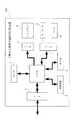
以下、本発明の実施の形態を図面に基づいて詳細に説明する。図1は本発明に係る二酸化炭素排出量の削減支援方法の実施に用いる二酸化炭素排出量削減支援装置の一実施の形態の要部を示すブロック構成図である。 Hereinafter, embodiments of the present invention will be described in detail with reference to the drawings. FIG. 1 is a block diagram showing a main part of an embodiment of a carbon dioxide emission reduction support apparatus used for carrying out the carbon dioxide emission reduction support method according to the present invention.
この二酸化炭素排出量削減支援装置100は、プロセッサや記憶装置からなるハードウェアと、これらのハードウェアと協働して各種機能を実現させるプログラムとによって実現される。具体的には、パーソナルコンピュータにプログラムがインストールされ、このインストールされたプログラムに従うCPUの処理動作として実現される The carbon dioxide emission
図1において、1はCPU、2はRAM、3はROM、4はハードディスクなどの記憶装置、5〜7はインターフェース、8はディスプレイ、9はキーボード、10はマウスである。CPU1はインターフェース5〜7を介して与えられる各種入力情報を得て、RAM2にアクセスしながら、ROM3や記憶装置4に格納されたプログラムに従って動作する。 In FIG. 1, 1 is a CPU, 2 is a RAM, 3 is a ROM, 4 is a storage device such as a hard disk, 5-7 is an interface, 8 is a display, 9 is a keyboard, and 10 is a mouse. The CPU 1 obtains various input information given via the
記憶装置4には、本実施の形態特有のプログラムとして二酸化炭素排出量の削減支援プログラムが格納されている。この二酸化炭素排出量の削減支援プログラムは、例えばCD−ROMなどの記録媒体に記録された状態で提供され、この記録媒体から読み出されて記録装置4にインストールされている。 The storage device 4 stores a carbon dioxide emission reduction support program as a program unique to the present embodiment. This carbon dioxide emission reduction support program is provided in a state where it is recorded on a recording medium such as a CD-ROM, for example, and is read from this recording medium and installed in the recording apparatus 4.
先ず、この二酸化炭素排出量削減支援装置100での二酸化炭素排出量の削減支援プログラムに従う動作について説明する前に、この削減支援プログラムに用いられる基本的な考え方について説明する。なお、以下において、通信機器は単に機器と呼ぶ。また、この実施の形態では、機器を買換えることが本発明でいう更改に相当する。 First, before explaining the operation of the carbon dioxide emission
〔機器(i)の1年間あたりの二酸化炭素(CO2)の排出量〕
LCA(ライフサイクルアセスメント)の考え方を用いれば、機器(i)の製造時、使用時、廃棄時を考慮した1年間あたりのCO2排出量の式は、下記の(1)式のように表される。[Emissions of carbon dioxide (CO2) per year from equipment (i)]
Using the concept of LCA (life cycle assessment), the equation for CO2 emissions per year taking into account the production, use, and disposal of equipment (i) is expressed as the following formula (1). The
1年間のCO2排出量(i)=1年間の使用時のCO2排出量(i)+製造時CO2排出量(i)/法定使用年数(i)+廃棄時CO2排出量(i)/法定使用年数(i)
・・・・(1)Annual CO2 emissions (i) = CO2 emissions during use for one year (i) + CO2 emissions during production (i) / Legal years of use (i) + CO2 emissions during disposal (i) / Legal use Year (i)
(1)
すなわち、機器(i)の1年間の使用時のCO2排出量(1年間の使用時のCO2排出量(i))に、「機器(i)の法定使用年数(法定使用年数(i))」あたりの「機器(i)の製造時CO2排出量(製造時CO2排出量(i))」と、「機器(i)の法定使用年数(法定使用年数(i))」あたりの「機器(i)の廃棄時CO2排出量(廃棄時CO2排出量(i))」を加えると、機器(i)の使用時だけではなく、製造時、廃棄時まで考慮した1年間のCO2排出量(1年間のCO2排出量(i))を表すことができる。 That is, the “legal use years of equipment (i) (legal use years (i))” is added to the CO2 emissions when equipment (i) is used for one year (CO2 emissions (i) when used for one year). "Equipment (i) during manufacture (CO2 emissions during manufacture (i))" and "equipment (i) per legal use period (legal use period (i))" ) CO2 emissions during disposal (CO2 emissions during disposal (i)) ”is added to the CO2 emissions for one year (1 year not only when using the device (i) but also during production and disposal) Of CO2 emissions (i)).
1年間あたりの使用時の排出量について説明する。使用時の排出量は排出量原単位を用いて表すことができる。まず、排出量原単位について説明する。排出量原単位は典型値データ(排出量と経済活動量)を用いて下記の(2.1)式で定義される。ここで、経済活動量とは電力消費量(エネルギー消費量)、人の移動、物の移動等を表す(例えば、非特許文献2参照)。
排出量原単位=排出量/経済活動量 ・・・・(2.1)Explain the amount of emissions per year during use. Emissions during use can be expressed in terms of emissions intensity. First, the emissions unit will be described. The basic unit of emissions is defined by the following formula (2.1) using typical value data (emissions and economic activity). Here, the amount of economic activity represents power consumption (energy consumption), movement of people, movement of goods, and the like (for example, see Non-Patent Document 2).
Emission basic unit = Emissions / Economic activity (...) (2.1)
(2.1)式の経済活動量として電力消費量をとりあげる。上記の排出量原単位を用いると、機器(i)の使用時のCO2の1年間あたりの排出量(i)は下記の(2.2)式で表される。
1年間の使用時のCO2排出量(i)=排出量原単位(i)×1年間の電力消費量(i,j≠i) ・・・・(2.2)The power consumption is taken up as the economic activity of equation (2.1). When the above emission basic unit is used, the annual emission amount (i) of CO2 when the device (i) is used is expressed by the following equation (2.2).
CO2 emissions during the year of use (i) = basic unit of emissions (i) x annual power consumption (i, j ≠ i) (2.2)
(2.2)式でjは機器(i)と通信接続している機器を表すインデックスである。機器(i)からの出発した情報が到達するのが機器(j)である。あるいは、機器(j)からの出発した情報が到達するのが機器(i)である。電力消費量(i,j≠i)は機器(i)と機器(j)の間で発生する電力消費量を表す。 In the equation (2.2), j is an index representing a device connected to the device (i). It is the device (j) that the departure information from the device (i) arrives. Alternatively, it is the device (i) that the departure information from the device (j) arrives. The power consumption (i, j ≠ i) represents the power consumption generated between the device (i) and the device (j).
例えば、機器(i)からの出発した情報が到達するのが機器(j)である場合に、電力消費量は機器(i)からアースに流れる電流による電力消費量と、機器(i)から出力して接続ケーブルを経由して、機器(j)に入力する電流による電力消費量に依存する。機器(j)からの出発した情報が到達するのが機器(i)である場合に、電力消費量は機器(j)からアースに流れる電流による電力消費量と、機器(j)から出力して接続ケーブルを経由して、機器(i)に入力する電流による電力消費量に依存する。機器(i)と機器(j)が接続していない場合には電力消費量(i,j)=0となる。 For example, when the departure information from the device (i) reaches the device (j), the power consumption is the power consumption due to the current flowing from the device (i) to the ground and the output from the device (i). And depends on the power consumption by the current input to the device (j) via the connection cable. When the starting information from the device (j) arrives at the device (i), the power consumption is output from the device (j) and the power consumption due to the current flowing from the device (j) to the ground. It depends on the power consumption due to the current input to the device (i) via the connection cable. When the device (i) and the device (j) are not connected, the power consumption (i, j) = 0.
ここで、機器(i)の1年間の使用時のCO2排出量は(2.2)式で表されるので、(1)式は下記の(3)式で表される。
1年間のCO2排出量(i)=排出量原単位(i)×1年間の電力消費量(i,j≠i)+製造時CO2排出量(i)/法定使用年数(i)+廃棄時CO2排出量(i)/法定使用年数(i) ・・・・(3)Here, since CO2 discharge | emission amount at the time of 1 year use of apparatus (i) is represented by (2.2) Formula, (1) Formula is represented by the following (3) Formula.
Annual CO2 emissions (i) = Emission basic unit (i) x Annual electric power consumption (i, j ≠ i) + CO2 emissions during production (i) / Legal years of use (i) + Disposal CO2 emissions (i) / Legal years (i) (3)
〔機器(i)の買換金額あたりのCO2排出量の削減量〕
ここで、(3)式に対して、機器(i)の買換金額あたりのCO2排出量の変化を導く。これは買換えに必要な費用あたりでCO2の排出量削減にもっとも効果のある買換え対象の機器(i)を求めるためである。これは崖から球を転がしたときに最大傾斜方向に球が進むというアナロジ(数学的な最適化手法でいうところの最急降下法)を利用している(例えば、非特許文献3参照)。[Reductions in CO2 emissions per replacement amount of equipment (i)]
Here, a change in the CO2 emission amount per replacement amount of the device (i) is derived from the equation (3). This is because a replacement target device (i) that is most effective in reducing CO2 emission per cost required for replacement is obtained. This utilizes an analogy (the steepest descent method in the mathematical optimization method) that the sphere advances in the maximum inclination direction when rolling the sphere from the cliff (see, for example, Non-Patent Document 3).
(3)式において、買換金額あたりのCO2排出量の変化を求める。機器(i)を買換えた場合のCO2排出量の削減量をΔCO2排出量(i)、買換金額をΔ買換金額(i)であらわすと、機器(i)の買換金額あたりのCO2排出量の削減量は下記の(4)式でであらわすことができる。
ΔCO2排出量(i)/Δ買換金額(i)=
(Δ排出量原単位(i)/Δ買換金額(i))×1年間の電力消費量(i,j≠i)
+排出量原単位(i)×(Δ1年間の電力消費量(i,j≠i)/Δ買換金額(i))
+排出量原単位(j≠i)×(Δ1年間の電力消費量(i,j≠i)/Δ買換金額(i))
+(Δ製造時CO2排出量(i)/Δ買換金額(i))×(1/法定使用年数(i))
+製造時CO2排出量(i)×(Δ(1/法定使用年数(i))/Δ買換金額(i))
+(Δ廃棄時CO2排出量(i)/Δ買換金額(i))×(1/法定使用年数(i))
+廃棄時CO2排出量(i)×(Δ(1/法定使用年数(i))/Δ買換金額(i))
・・・・(4)In equation (3), the change in CO2 emissions per replacement amount is obtained. When the reduction amount of CO2 emission when the device (i) is replaced is represented by ΔCO2 emission amount (i) and the replacement amount is represented by Δ replacement amount (i), CO2 per replacement amount of the device (i) The amount of emission reduction can be expressed by the following equation (4).
ΔCO2 emission (i) / Δ replacement amount (i) =
(Δ emission basic unit (i) / Δ replacement amount (i)) × annual power consumption (i, j ≠ i)
+ Emission basic unit (i) x (Δ1 annual power consumption (i, j ≠ i) / Δ replacement amount (i))
+ Emission basic unit (j ≠ i) x (Δ1 year electricity consumption (i, j ≠ i) / Δ replacement amount (i))
+ (Δ CO2 emissions during production (i) / Δ Amount of replacement (i)) x (1 / Legal years (i))
+ Manufacturing CO2 emissions (i) x (Δ (1 / statutory years of use (i)) / Δ amount of replacement (i))
+ (Δ CO2 emissions at the time of disposal (i) / Δ Amount of replacement (i)) x (1 / Legal years of service (i))
+ CO2 emissions at the time of disposal (i) x (Δ (1 / legal age (i)) / Δ amount of replacement (i))
.... (4)
〔(4)式の第2項の説明〕
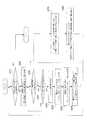
(4)式の第2項の「排出量原単位(i)×(Δ1年間の電力消費量(i,j≠i)/Δ買換金額(i))」について図2および図3を用いて説明する。[Explanation of the second term of equation (4)]
2 and FIG. 3 for the second term of the formula (4), “Emission basic unit (i) × (Δ1 annual power consumption (i, j ≠ i) / Δ replacement amount (i))”. I will explain.
図2において、200は機器iの入力回路、300は機器jの出力回路を示す。機器iの入力回路100はNPN型のトランジスタTr1により構成され、トランジスタTr1のコレクタは抵抗Ricを介して電圧源Vと接続している。トランジスタTr1のベースは抵抗Rib(入力抵抗)を介して機器jの出力回路300と接続している。トランジスタTr1のエミッタは抵抗Rieを介して(または直接)グランドと接続している。抵抗Ricに流れる電流はIis+Iioutである。ここでIioutは機器iの後段に流れる電流である。抵抗Ribに流れる電流はIiinである。抵抗Rieを流れる電流は抵抗Ricに流れる電流からIioutを引いたIisとベースに流れる電流Iiinの和、Iiin+Iisと表される。 In FIG. 2,
ここで、機器iを取り替えて、ベース電流IiinがΔIiinだけ変化したとする(図3参照)。この場合、機器iの電力の変化は、入力抵抗Ribに流れる電流Iiinを用い、以下の式で表すことができる。
Rib・Iiin2−Rib・(Iiin+ΔIiin)2=−Rib・ΔIiin・(2Iiin+ΔIiin)Here, it is assumed that the device i is replaced and the base current Iiin changes by ΔIiin (see FIG. 3). In this case, the change in the power of the device i can be expressed by the following equation using the current Iiin flowing through the input resistor Rib.
Rib · Iiin2 −Rib · (Iiin + ΔIiin)2 = −Rib · ΔIiin · (2Iiin + ΔIiin)
よって、機器iの入力電流Iiinと、機器iを取り替えた想定したときの入力電流の差ΔIiinと、機器iの入力抵抗Ribとにより、電力の変化「−Rib・ΔIiin・(2Iiin+ΔIiin)」を計算することができる。なお、機器iの入力電流iinと入力抵抗Ribは機器iに通常表示している表示値を用いてもよいし、実測値を用いてもよい。 Therefore, the power change “−Rib · ΔIiin · (2Iiin + ΔIiin)” is calculated from the input current Iiin of the device i, the difference ΔIiin when the device i is replaced, and the input resistance Rib of the device i. can do. As the input current iin and the input resistance Rib of the device i, display values normally displayed on the device i may be used, or measured values may be used.
(4)式の第2項は、機器iを買換えることにより機器jに関係する電力消費量が変化して、機器jに関するCO2の排出量が削減されることを意味している。機器iと機器jとが接続関係にない場合には電力消費量(i,j)=0であるため、Δ1年間の電力消費量(i,j≠i)/Δ買換金額(i)は機器iと機器jとが接続している場合のみゼロではない値をとり得る。このため、(4)式は単なる機器の集まりではなく、通信ネットワーク内で評価しなければならない。 The second term of the equation (4) means that the power consumption related to the device j is changed by the replacement of the device i, and the CO2 emission related to the device j is reduced. When the device i and the device j are not connected, the power consumption (i, j) = 0, so that Δ1 year power consumption (i, j ≠ i) / Δ replacement amount (i) is It can take a non-zero value only when device i and device j are connected. For this reason, equation (4) is not just a collection of devices, but must be evaluated within the communication network.
〔(4)式の第3項の説明〕
(4)式の第3項の「排出量原単位(j≠i)×(Δ1年間の電力消費量(i,j≠i)/Δ買換金額(i))」について図2および図3を用いて説明する。図2において、機器jの出力回路200は、NPN型のトランジスタTr2により構成され、トランジスタTr2のコレクタは抵抗Rjc(出力抵抗)を介して電圧源Vと接続している。トランジスタTrのベースは抵抗Rjbを介して機器jの前段回路と接続している。トランジスタTr2のエミッタは抵抗Rjeを介して(または直接)グランドと接続している。抵抗Rjcに流れる電流はIjs+Iiinである。ここでIiinは機器iのベースに流れる電流である。抵抗Rjbに流れる電流はIjinである。抵抗Rjeを流れる電流は抵抗Rjcに流れる電流からIiinを引いたIjsとベースに流れる電流Ijinの和、Ijin+Ijsと表される。[Explanation of the third term of equation (4)]
FIG. 2 and FIG. 3 regarding the “emission basic unit (j ≠ i) × (Δ1 annual power consumption (i, j ≠ i) / Δ replacement amount (i))” in the third term of the equation (4) Will be described. In FIG. 2, the
ここで、機器iを取り替えてベース電流IiinがΔIiinだけ変化した場合には、機器jの抵抗Rjcを流れる電流がΔIiin変化することになる(図3参照)。したがって、機器iを取り替えたことによる機器jの電力の変化は、出力抵抗Rjcを流れる電流Ijs+Iiinを用いて以下の式で表すことができる。
Rjc・(Ijs+Iiin)2−Rjc・(Ijs+Iiin+ΔIiin)2=−Rjc・ΔIiin・(2・Ijs+2・Iiin+ΔIiin)Here, when the device i is replaced and the base current Iiin changes by ΔIiin, the current flowing through the resistor Rjc of the device j changes by ΔIiin (see FIG. 3). Therefore, the change in the power of the device j due to the replacement of the device i can be expressed by the following equation using the current Ijs + Iiin flowing through the output resistance Rjc.
Rjc · (Ijs + Iiin)2 −Rjc · (Ijs + Iiin + ΔIiin)2 = −Rjc · ΔIiin · (2 ·
よって、機器iの入力電流Iiinと、機器iを取り替えた想定したときの入力電流の差ΔIiinと、機器jの出力抵抗Rjcと、機器jの出力電流ijsにより、電力の変化「−Rjc・ΔIiin・(2・Ijs+2・Iiin+ΔIiin)を計算することができる。機器iの入力電流iinは機器iに通常表示している表示値を用いてもよいし、実測値を用いてもよく、機器jの出力電流ijsと出力抵抗Rjcは機器jに通常表示している表示値を用いてもよいし、実測値を用いてもよい。 Therefore, the change in power “−Rjc · ΔIiin” is determined by the input current Iiin of the device i, the difference ΔIiin when the device i is replaced, the output resistance Rjc of the device j, and the output current ijs of the device j. (2 ·
(4)式の第3項は、機器iを買換えることにより機器jに関係する電力消費量が変化して、機器jに関するCO2の排出量が削減されることを意味している。機器iと機器jとが接続関係にない場合には電力消費量(i,j)=0であるため、Δ1年間の電力消費量(i,j≠i)/Δ買換金額(i)は機器iと機器jとが接続している場合のみゼロではない値をとり得る。このため、(4)式は単なる機器の集まりではなく、通信ネットワーク内で評価しなければならない。この(4)式の第3項により、買換える機器が通信ネットワーク内の他の機器に及ぼすCO2排出量の削減効果まで考慮してCO2排出量を削減できる。 The third term in the equation (4) means that the power consumption related to the device j is changed by the replacement of the device i, and the CO2 emission related to the device j is reduced. When the device i and the device j are not connected, the power consumption (i, j) = 0, so that Δ1 year power consumption (i, j ≠ i) / Δ replacement amount (i) is It can take a non-zero value only when device i and device j are connected. For this reason, equation (4) is not just a collection of devices, but must be evaluated within the communication network. According to the third term of the equation (4), the CO2 emission amount can be reduced in consideration of the effect of reducing the CO2 emission amount that the device to be replaced has on other devices in the communication network.
〔買換え機器の選択〕
通信システムから発生するCO2排出量を与えられた予算内で最大に削減する方法を次に示す。ある通信ネットワークに含まれるすべての機器についてΔCO2排出量(i)/Δ買換金額(i)を計算し、次にこれらをすべての通信ネットワークについて計算する。[Select replacement equipment]
A method for reducing the CO2 emission generated from the communication system to the maximum within a given budget will be described below. [Delta] CO2 emissions (i) / [Delta] replacement amount (i) is calculated for all devices included in a certain communication network, and then these are calculated for all communication networks.
f=Σすべての通信ネットワークΣすべての機器i(ΔCO2排出量(i)/Δ買換金額(i))
=Σすべての通信ネットワークΣすべての機器i(
(Δ排出量原単位(i)/Δ買換金額(i))×1年間の電力消費量(i,j≠i)
+排出量原単位(i)×(Δ1年間の電力消費量(i,j≠i)/Δ買換金額(i))
+Σj(排出量原単位(j)×(Δ1年間の電力消費量(i,j≠i)/Δ買換金額(i)))
+(Δ製造時CO2排出量(i)/Δ買換金額(i))×(1/法定使用年数(i))
+製造時CO2排出量(i)×(Δ(1/法定使用年数(i))/Δ買換金額(i))
+(Δ廃棄時CO2排出量(i)/Δ買換金額(i))×(1/法定使用年数(i))
+廃棄時CO2排出量(i)×(Δ(1/法定使用年数(i))/Δ買換金額(i)))
・・・・(5)f = Σ All communication networks Σ All devices i (ΔCO2 emissions (i) / Δ Replacement amount (i))
= ΣAll communication networksΣAll devices i (
(Δ emission basic unit (i) / Δ replacement amount (i)) × annual power consumption (i, j ≠ i)
+ Emission basic unit (i) x (Δ1 annual power consumption (i, j ≠ i) / Δ replacement amount (i))
+ Σj (Emission basic unit (j) x (Δ1 year power consumption (i, j ≠ i) / Δ replacement amount (i)))
+ (Δ CO2 emissions during production (i) / Δ Amount of replacement (i)) x (1 / Legal years (i))
+ Manufacturing CO2 emissions (i) x (Δ (1 / statutory years of use (i)) / Δ amount of replacement (i))
+ (Δ CO2 emissions at the time of disposal (i) / Δ Amount of replacement (i)) x (1 / Legal years of service (i))
+ CO2 emissions during disposal (i) x (Δ (1 / legal age (i)) / Δ replacement amount (i))
(5)
(5)式で示される目的関数(CO2排出量の削減量)fを最大にする機器iの買換えを、すなわち既存の機器iに対して買換候補として定められた機器iへの買換え(買換え機器の選択)を、制約条件下で行う。
制約 機器買換えの総額<予算
目的関数 f → max ・・・・(6)Replacement of the device i that maximizes the objective function (CO2 emission reduction amount) f expressed by the equation (5), that is, replacement of the existing device i with a device i that is determined as a replacement candidate. (Select replacement equipment) under restricted conditions.
Constraint Total purchase of equipment <Budget Objective function f → max (6)
これにより、
(1)費用あたりで最もCO2排出量を削減できる機器の買換えが可能となる。
(2)CO2排出量の原単位の大きい機器ではなく、実際の電力消費量等による排出量の大きな機器を買換えることが可能になる。
(3)買換える機器が通信ネットワーク内の他の機器に及ぼす二酸化炭素排出量の削減効果まで考慮して二酸化炭素排出量を削減できる。
というような効果が得られる。This
(1) It is possible to replace a device that can reduce CO2 emissions most per unit cost.
(2) It is possible to replace a device with a large emission amount due to an actual power consumption amount, instead of a device with a large CO2 emission basic unit.
(3) Carbon dioxide emissions can be reduced in consideration of the reduction effect of carbon dioxide emissions on other devices in the communication network by the device to be replaced.
Such an effect is obtained.
次に、上述した基本的な考え方に基づいて実行される二酸化炭素排出量削減支援装置100での二酸化炭素排出量の削減支援プログラムの動作について、図4および図5に示すフローチャートを用いて説明する。 Next, the operation of the carbon dioxide emission reduction support program in the carbon dioxide emission
〔通信経路の作成〕
図4は二酸化炭素排出量削減支援装置100において後述する機器買換ペアの検索対象とする通信経路を作成するアルゴリズムのフローチャートである。[Create communication path]
FIG. 4 is a flowchart of an algorithm for creating a communication path to be searched for a device replacement pair, which will be described later, in the carbon dioxide emission
通信経路を作成するにはあらかじめ通信ネットワークと構成機器の配線図を用意する。そして、この通信ネットワークと構成機器の配線図より、通信経路の構成機器を抽出する(ステップS110)。次に、構成機器の接続関係を抽出する(ステップS120)。そして、抽出した構成において、送信側端末をスタートノードとする(ステップS130)。そして、通信系路上の構成機器をノードとし、接続をエッジとした通信経路グラフを構築し(ステップS140)、受信側端末をエンドノードとする(ステップS150)。このようにして、CPU1は、すべての通信経路について、送信側端末をスタートノードとし、通信経路上の構成機器をノードとし、接続をエッジとし、受信側端末をエンドノードとした通信経路を作成し、この作成した通信経路(通信ネットワーク)を記憶装置4に保存する。 To create a communication path, prepare a wiring diagram of the communication network and components. Then, the constituent devices of the communication path are extracted from the communication network and the wiring diagram of the constituent devices (step S110). Next, the connection relationship of the component devices is extracted (step S120). In the extracted configuration, the transmission side terminal is set as the start node (step S130). Then, a communication path graph is constructed with the components on the communication path as nodes and connections as edges (step S140), and the receiving terminal is set as an end node (step S150). In this way, for all communication paths, the CPU 1 creates a communication path with the transmission side terminal as the start node, the component device on the communication path as the node, the connection as the edge, and the reception side terminal as the end node. The created communication path (communication network) is stored in the storage device 4.
〔買換え機器の選択〕
図5は二酸化炭素排出量削減支援装置100において買換え機器を選択するアルゴリズムのフローチャートである。CPU1は、記憶装置4に保存されている通信経路中の機器について、予算金額内で購入できる機器が存在するか否かを判断する(ステップS210)。予算金額内で購入できる機器が存在すれば(ステップS210のYES)、ステップ220に処理を移し、予算金額内で購入できる機器が存在しなければ(ステップS210のNO)、処理を終了する。[Select replacement equipment]
FIG. 5 is a flowchart of an algorithm for selecting a replacement device in the carbon dioxide emission
CPU1は、予算金額内で購入できる機器が存在すると判断すると(ステップS210のYES)、機器買換えペアの一覧を作成する(ステップS220)。すなわち、予算金額内で購入できる全ての機器について、既存機器とその既存機器に対する買換候補の機器とを買換えペアとする機器の一覧を作成する(図6参照)。 When determining that there is a device that can be purchased within the budget amount (YES in step S210), the CPU 1 creates a list of device replacement pairs (step S220). That is, for all the devices that can be purchased within the budget amount, a list of devices having a replacement pair of an existing device and a replacement candidate device for the existing device is created (see FIG. 6).
そして、この機器買換えペアの一覧から最初の買換えペアを検索し(ステップS230のNO)、また記憶装置4に保存されている通信経路から最初の通信経路を検索し(ステップS240、S250)、その買換えペアの機器(i)について、機器(i)の電力の変化「−Rib・ΔIiin・(2Iiin+ΔIiin)」を計算し(ステップS252)、機器(j)の電力の変化「−Rjc・ΔIiin・(2・Ijs+2・Iiin+ΔIiin)」を計算する(ステップS254)。そして、その買換ペアの機器(i)について、ステップS250で検索した通信経路のΔCO2排出量(i)/Δ買換金額(i)を(4)式を用いて計算する(ステップS260)。 Then, the first replacement pair is searched from the list of device replacement pairs (NO in step S230), and the first communication path is searched from the communication paths stored in the storage device 4 (steps S240 and S250). For the device (i) of the replacement pair, the power change “−Rib · ΔIiin · (2Iiin + ΔIiin)” of the device (i) is calculated (step S252), and the power change “−Rjc · ΔIiin · (2 ·
CPU1は、ステップS240〜S260の処理を繰り返すことにより、最初の買換えペアの機器(i)について、記憶装置4に保存されている全ての通信経路について、ΔCO2排出量(i)/Δ買換金額(i)を計算する。そして、記憶装置4に保存されている全ての通信経路について、ΔCO2排出量(i)/Δ買換金額(i)の計算が終了すれば(ステップS240のYES)、ステップS230へ戻り、機器買換えペアの一覧から次の買換えペアを検索し、ステップS240〜S260の処理動作を繰り返す。これにより、次のペアの機器(i)についても、同様にして、記憶装置4に保存されている全ての通信経路について、ΔCO2排出量(i)/Δ買換金額(i)が計算される。 The CPU 1 repeats the processes of steps S240 to S260, so that ΔCO2 emission amount (i) / Δ replacement for all communication paths stored in the storage device 4 for the device (i) of the first replacement pair. Calculate the amount (i). When the calculation of ΔCO2 emission amount (i) / Δreplacement amount (i) is completed for all communication paths stored in the storage device 4 (YES in step S240), the process returns to step S230 to purchase the device. The next replacement pair is searched from the list of replacement pairs, and the processing operations of steps S240 to S260 are repeated. Accordingly, ΔCO2 emission amount (i) / Δ replacement amount (i) is calculated for all communication paths stored in the storage device 4 in the same manner for the next pair of devices (i). .
CPU1は、このような処理動作を繰り返し、機器買換えペアの一覧中の全ての買換えペアについて、全ての通信経路のΔCO2排出量(i)/Δ買換金額(i)の計算を終えると(ステップS230のYES)、その計算したΔCO2排出量(i)/Δ買換金額(i)の中からΔCO2排出量(i)/Δ買換金額(i)が最大となる買換えペア(既存機器、買換候補の機器)を選択する(ステップS270)。このステップS210〜S270の処理が前述した(5)〜(6)式の処理を実行することに相当する。そして、CPU1は、この選択した買換えペアの機器をディスプレイ8に表示する(ステップS280)。 When the CPU 1 repeats such processing operation and finishes calculating ΔCO2 emission amount (i) / Δ replacement amount (i) for all communication paths for all replacement pairs in the list of device replacement pairs. (YES in step S230), the replacement pair (existing) having the largest ΔCO2 emission amount (i) / Δreplacement amount (i) among the calculated ΔCO2 emission amount (i) / Δreplacement amount (i) A device or a replacement candidate device is selected (step S270). The processing of steps S210 to S270 corresponds to executing the processing of the above-described equations (5) to (6). The CPU 1 displays the selected replacement pair device on the display 8 (step S280).
この買換えペアの表示に従い、その買換えペアの既存機器を買換候補の機器で置き換えるようにすれば、予算金額内でCO2排出量の削減量を最大とし、効率的にCO2排出量を削減することができるようになる。 By replacing the existing device of the replacement pair with the replacement candidate device according to the replacement pair display, the CO2 emission reduction amount is maximized within the budget amount, and the CO2 emission amount is efficiently reduced. Will be able to.
図7に二酸化炭素排出量削減支援装置100の要部の機能ブロック図を示す。二酸化炭素排出量削減支援装置100は、図4に示したステップS110〜S150によって作成された全ての通信経路を記憶する通信経路記憶部101と、図5に示したステップS220で作成された機器買換えペアの一覧TB1を記憶する機器買換えペア一覧記憶部102と、図5に示したステップS230〜260の処理を繰り返し実行する演算部103と、図5に示したステップS270の処理を実行する買換えペア選択部104と、図5に示したステップS280の処理を実行する買換機器推奨部105とを備えている。 FIG. 7 shows a functional block diagram of the main part of the carbon dioxide emission
演算部103は、機器買換えペア一覧記憶部102に記憶されている全ての買換えペア(A,A’、・・・・、Z,Z’)について、通信経路記憶部101に記憶されている全ての通信経路(通信経路1〜N)のΔCO2排出量(i)/Δ買換金額(i)をα(i)(αA1〜αAN・・・・αZ1〜αZN)として計算し、買換えペア選択部104に送る。買換えペア選択部104は、演算部103によって計算されたα(i)の中から最大のものを探し出し、削減量α(i)が最大の買換えペアを機器買換えペアの一覧TB1から選択する。買換機器推奨部105は、買換えペア選択部104が選択した買換えペアの機器を表示する。The
本発明の二酸化炭素排出量の削減支援方法、装置およびプログラムは、効率的な二酸化炭素排出量の削減を可能とする二酸化炭素排出量の削減支援方法、装置およびプログラムとして、情報通信サービスなど各種の分野で利用することが可能である。 The carbon dioxide emission reduction support method, apparatus, and program according to the present invention includes a carbon dioxide emission reduction support method, apparatus, and program that enable efficient carbon dioxide emission reduction. It can be used in the field.
1…CPU、2…RAM、3…ROM、4…記憶装置、5〜7…インターフェース、8…ディスプレイ、9…キーボード、10…マウス、101…通信経路記憶部、102…機器買換えペア一覧記憶部、103…演算部、104…買換えペア選択部、105…買換機器推奨部、TB1…機器買換えペアの一覧。 DESCRIPTION OF SYMBOLS 1 ... CPU, 2 ... RAM, 3 ... ROM, 4 ... Storage device, 5-7 ... Interface, 8 ... Display, 9 ... Keyboard, 10 ... Mouse, 101 ... Communication path storage unit, 102 ... Device replacement pair list storage , 103... Operation unit, 104... Replacement pair selection unit, 105... Replacement device recommendation unit, TB 1.
Claims (7)
Translated fromJapanese前記更改候補の通信機器と既存の通信機器とのペアのそれぞれについて更改に必要な費用あたりの二酸化炭素排出量の削減量を算出する削減量算出ステップと、
前記削減量算出ステップによって算出された費用あたりの二酸化炭素排出量の削減量が最大となる更改候補の通信機器と既存の通信機器とのペアを選択する選択ステップと
を備えることを特徴とする二酸化炭素排出量の削減支援方法。A storage step for storing a pair of a renewal candidate communication device and an existing communication device, which is defined as a constraint that the renewal can be performed within the budget amount;
A reduction amount calculating step for calculating a reduction amount of carbon dioxide emissions per cost required for renewal for each pair of the communication device as a candidate for renewal and an existing communication device;
And a selection step of selecting a pair of a communication device that is a candidate for renewal and an existing communication device that maximizes the reduction amount of carbon dioxide emissions per cost calculated by the reduction amount calculation step. Carbon emission reduction support method.
前記削減量算出ステップは、前記費用あたりの二酸化炭素排出量の削減量をライフサイクルアセスメントの計算式を用いて算出する
ことを特徴とする二酸化炭素排出量の削減支援方法。In the carbon dioxide emission reduction support method according to claim 1,
The reduction amount calculating step calculates a reduction amount of carbon dioxide emissions per cost using a calculation formula of life cycle assessment. A method for supporting reduction of carbon dioxide emissions.
前記削減量算出ステップは、前記更改候補の通信機器が通信ネットワーク内の他の通信機器にまで及ぼす二酸化炭素排出量削減効果まで考慮して、前記費用あたりの二酸化炭素排出量の削減量を算出する
ことを特徴とする二酸化炭素排出量の削減支援方法。In the carbon dioxide emission reduction support method according to claim 1 or 2,
The reduction amount calculating step calculates a reduction amount of the carbon dioxide emission amount per the cost in consideration of the carbon dioxide emission reduction effect that the renewal candidate communication device has on other communication devices in the communication network. A carbon dioxide emission reduction support method characterized by that.
前記更改候補の通信機器と既存の通信機器とのペアのそれぞれについて更改に必要な費用あたりの二酸化炭素排出量の削減量を算出する削減量算出手段と、
前記削減量算出手段によって算出された費用あたりの二酸化炭素排出量の削減量が最大となる更改候補の通信機器と既存の通信機器とのペアを選択する選択手段と
を備えることを特徴とする二酸化炭素排出量の削減支援装置。A storage means for storing a pair of a renewal candidate communication device and an existing communication device, which is defined as a restriction condition that the renewal can be performed within the budget amount;
A reduction amount calculating means for calculating a reduction amount of carbon dioxide emissions per cost required for renewal for each pair of the renewal candidate communication device and the existing communication device;
And a selection means for selecting a pair of a renewal candidate communication device and an existing communication device that maximizes the reduction amount of carbon dioxide emissions per cost calculated by the reduction amount calculation means. Carbon emission reduction support equipment.
前記削減量算出手段は、前記費用あたりの二酸化炭素排出量の削減量をライフサイクルアセスメントの計算式を用いて算出する
ことを特徴とする二酸化炭素排出量の削減支援装置。In the carbon dioxide emission reduction support apparatus according to claim 4,
The reduction amount calculating means calculates a reduction amount of the carbon dioxide emission amount per cost using a life cycle assessment calculation formula.
前記削減量算出手段は、前記更改候補の通信機器が通信ネットワーク内の他の通信機器にまで及ぼす二酸化炭素排出量削減効果まで考慮して、前記費用あたりの二酸化炭素排出量の削減量を算出する
ことを特徴とする二酸化炭素排出量の削減支援装置。In the carbon dioxide emission reduction support apparatus according to claim 4 or 5,
The reduction amount calculation means calculates a reduction amount of the carbon dioxide emission amount per cost in consideration of the carbon dioxide emission reduction effect that the renewal candidate communication device has on other communication devices in the communication network. A carbon dioxide emission reduction support device characterized by that.
Priority Applications (1)
| Application Number | Priority Date | Filing Date | Title |
|---|---|---|---|
| JP2011128956AJP5385337B2 (en) | 2011-06-09 | 2011-06-09 | Carbon dioxide emission reduction support method, apparatus and program |
Applications Claiming Priority (1)
| Application Number | Priority Date | Filing Date | Title |
|---|---|---|---|
| JP2011128956AJP5385337B2 (en) | 2011-06-09 | 2011-06-09 | Carbon dioxide emission reduction support method, apparatus and program |
Publications (2)
| Publication Number | Publication Date |
|---|---|
| JP2012256210Atrue JP2012256210A (en) | 2012-12-27 |
| JP5385337B2 JP5385337B2 (en) | 2014-01-08 |
Family
ID=47527716
Family Applications (1)
| Application Number | Title | Priority Date | Filing Date |
|---|---|---|---|
| JP2011128956AActiveJP5385337B2 (en) | 2011-06-09 | 2011-06-09 | Carbon dioxide emission reduction support method, apparatus and program |
Country Status (1)
| Country | Link |
|---|---|
| JP (1) | JP5385337B2 (en) |
Cited By (3)
| Publication number | Priority date | Publication date | Assignee | Title |
|---|---|---|---|---|
| CN116822917A (en)* | 2023-08-31 | 2023-09-29 | 国网湖北省电力有限公司经济技术研究院 | Power transmission and transformation equipment emission reduction optimization method and system based on electric power carbon footprint |
| JP7583206B1 (en)* | 2024-02-27 | 2024-11-13 | 東京瓦斯株式会社 | Carbon reduction measures proposing system and carbon reduction measures proposing method |
| WO2025004205A1 (en)* | 2023-06-28 | 2025-01-02 | 三菱電機株式会社 | Environmental improvement support device, environmental improvement support method, and environmental improvement support program |
Citations (3)
| Publication number | Priority date | Publication date | Assignee | Title |
|---|---|---|---|---|
| JP2009048244A (en)* | 2007-08-13 | 2009-03-05 | Asahi Kasei Homes Kk | Housing equipment selection support system |
| JP2009193237A (en)* | 2008-02-13 | 2009-08-27 | Hitachi Ltd | Product configuration information creation apparatus, program, and method |
| JP2010282279A (en)* | 2009-06-02 | 2010-12-16 | Business On Line Inc | Environmental housekeeping book system and server |
- 2011
- 2011-06-09JPJP2011128956Apatent/JP5385337B2/enactiveActive
Patent Citations (3)
| Publication number | Priority date | Publication date | Assignee | Title |
|---|---|---|---|---|
| JP2009048244A (en)* | 2007-08-13 | 2009-03-05 | Asahi Kasei Homes Kk | Housing equipment selection support system |
| JP2009193237A (en)* | 2008-02-13 | 2009-08-27 | Hitachi Ltd | Product configuration information creation apparatus, program, and method |
| JP2010282279A (en)* | 2009-06-02 | 2010-12-16 | Business On Line Inc | Environmental housekeeping book system and server |
Cited By (4)
| Publication number | Priority date | Publication date | Assignee | Title |
|---|---|---|---|---|
| WO2025004205A1 (en)* | 2023-06-28 | 2025-01-02 | 三菱電機株式会社 | Environmental improvement support device, environmental improvement support method, and environmental improvement support program |
| CN116822917A (en)* | 2023-08-31 | 2023-09-29 | 国网湖北省电力有限公司经济技术研究院 | Power transmission and transformation equipment emission reduction optimization method and system based on electric power carbon footprint |
| CN116822917B (en)* | 2023-08-31 | 2023-11-21 | 国网湖北省电力有限公司经济技术研究院 | Power transmission and transformation equipment emission reduction optimization method and system based on electric power carbon footprint |
| JP7583206B1 (en)* | 2024-02-27 | 2024-11-13 | 東京瓦斯株式会社 | Carbon reduction measures proposing system and carbon reduction measures proposing method |
Also Published As
| Publication number | Publication date |
|---|---|
| JP5385337B2 (en) | 2014-01-08 |
Similar Documents
| Publication | Publication Date | Title |
|---|---|---|
| US8230439B2 (en) | Green computing interchange switching function | |
| Ko et al. | Analysis of consumer preferences for electric vehicles | |
| Li et al. | Software Test Data Generation using Ant Colony Optimization. | |
| Wang et al. | Multi-objective fuzzy flexible job shop scheduling using memetic algorithm | |
| US20110125700A1 (en) | User model processing device | |
| US20150019173A1 (en) | Multiobjective optimization through user interactive navigation in a design space | |
| Rasoldier et al. | How realistic are claims about the benefits of using digital technologies for GHG emissions mitigation? | |
| JP5385337B2 (en) | Carbon dioxide emission reduction support method, apparatus and program | |
| CN103678531A (en) | Friend recommendation method and friend recommendation device | |
| JP6757936B2 (en) | Impact calculator, impact calculation method and program | |
| Reddy et al. | A study on effect of eWOM information on purchase intention for electric vehicles | |
| Khan et al. | Microsimulation of mobility assignment within an activity-based travel demand forecasting model | |
| JP2013010388A (en) | Vehicle operation plan preparation device | |
| JP2008108204A (en) | Environmental load evaluation system, method and program | |
| Kala et al. | Perceived value and adoption intention for 5G services in India: Moderating effect of environmental awareness | |
| Khatrouch et al. | Bio-inspired metaheuristics for the generalised discrete cost multicommodity network design problem | |
| Liu et al. | Unraveling spatiotemporal dynamics of ridesharing potential: Nonlinear effects of the built environment | |
| US11093517B2 (en) | Evaluation result display method, evaluation result display apparatus, and non-transitory computer-readable recording medium storing evaluation result display program | |
| JP2013080280A (en) | Method for determining optimum policy by using cyclic markov decision process, device, and computer program | |
| Chaganti et al. | Nearest Charging Station Identification for EV Using Machine Learning Techniques | |
| JP5963493B2 (en) | Cost estimation system, method and program | |
| JP2020035219A (en) | Device, method, and program for processing information | |
| US20210166155A1 (en) | Composite model generation method and information processing apparatus | |
| JP6477293B2 (en) | System operation support apparatus, system operation support method, and program thereof | |
| Wilson et al. | Evidence Synthesis of Indirect Impacts of Digitalisation on Energy and Emissions |
Legal Events
| Date | Code | Title | Description |
|---|---|---|---|
| A977 | Report on retrieval | Free format text:JAPANESE INTERMEDIATE CODE: A971007 Effective date:20130618 | |
| A131 | Notification of reasons for refusal | Free format text:JAPANESE INTERMEDIATE CODE: A131 Effective date:20130702 | |
| A521 | Request for written amendment filed | Free format text:JAPANESE INTERMEDIATE CODE: A523 Effective date:20130829 | |
| TRDD | Decision of grant or rejection written | ||
| A01 | Written decision to grant a patent or to grant a registration (utility model) | Free format text:JAPANESE INTERMEDIATE CODE: A01 Effective date:20131001 | |
| A61 | First payment of annual fees (during grant procedure) | Free format text:JAPANESE INTERMEDIATE CODE: A61 Effective date:20131003 | |
| R150 | Certificate of patent or registration of utility model | Ref document number:5385337 Country of ref document:JP Free format text:JAPANESE INTERMEDIATE CODE: R150 Free format text:JAPANESE INTERMEDIATE CODE: R150 | |
| S531 | Written request for registration of change of domicile | Free format text:JAPANESE INTERMEDIATE CODE: R313531 | |
| R350 | Written notification of registration of transfer | Free format text:JAPANESE INTERMEDIATE CODE: R350 | |
| S533 | Written request for registration of change of name | Free format text:JAPANESE INTERMEDIATE CODE: R313533 | |
| R360 | Written notification for declining of transfer of rights | Free format text:JAPANESE INTERMEDIATE CODE: R360 |